Introduction
On the bench today is the GE CSAC0250BZ, a 250W server power supply that’s earned its 80 PLUS Platinum badge. Built for efficiency, it takes 100-240V AC input and pushes a steady 12V/20.8A output, plus a 0.1A standby rail.
The exterior is geared for server-rack life, featuring an integrated handle, locking latch, status LED, and a rear gold-finger interface. Under the hood, it’s powered by a robust PFC + Half-Bridge LLC + Synchronous Rectification design. Let’s dive into the teardown to see the high-performance components and design choices that make this GE unit a reliable powerhouse.
Product Appearance
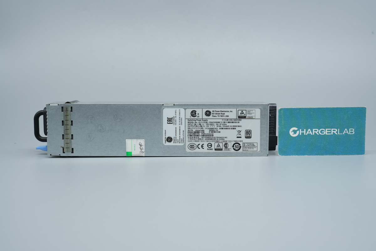
Encased in galvanized steel, this GE server power supply features a label on the front, along with a handle and AC input. Around the back, you'll find the gold-finger connector for server rack integration.
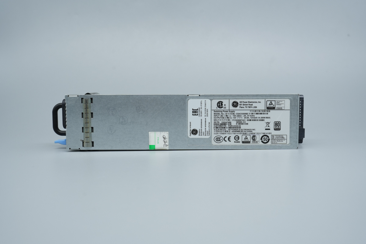
The left side is equipped with a grounding spring tab, while the right side features an info label.
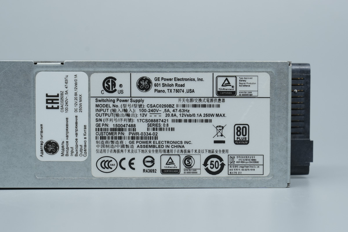
Power Supply Label Specs:
Model: CSAC0250BZ
Input: 100-240V~, 5A, 47-63Hz
Output: 12V ⎓ 20.8A; 12Vsb / 0.1A; 250W MAX.
Efficiency: 80 PLUS Platinum Certified
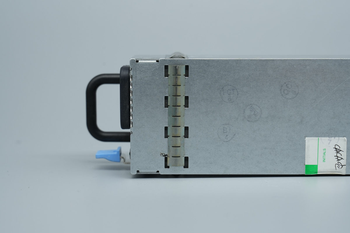
This is the metal grounding spring tab at the input end.
The rear side of the chassis is also equipped with a metal grounding spring tab.
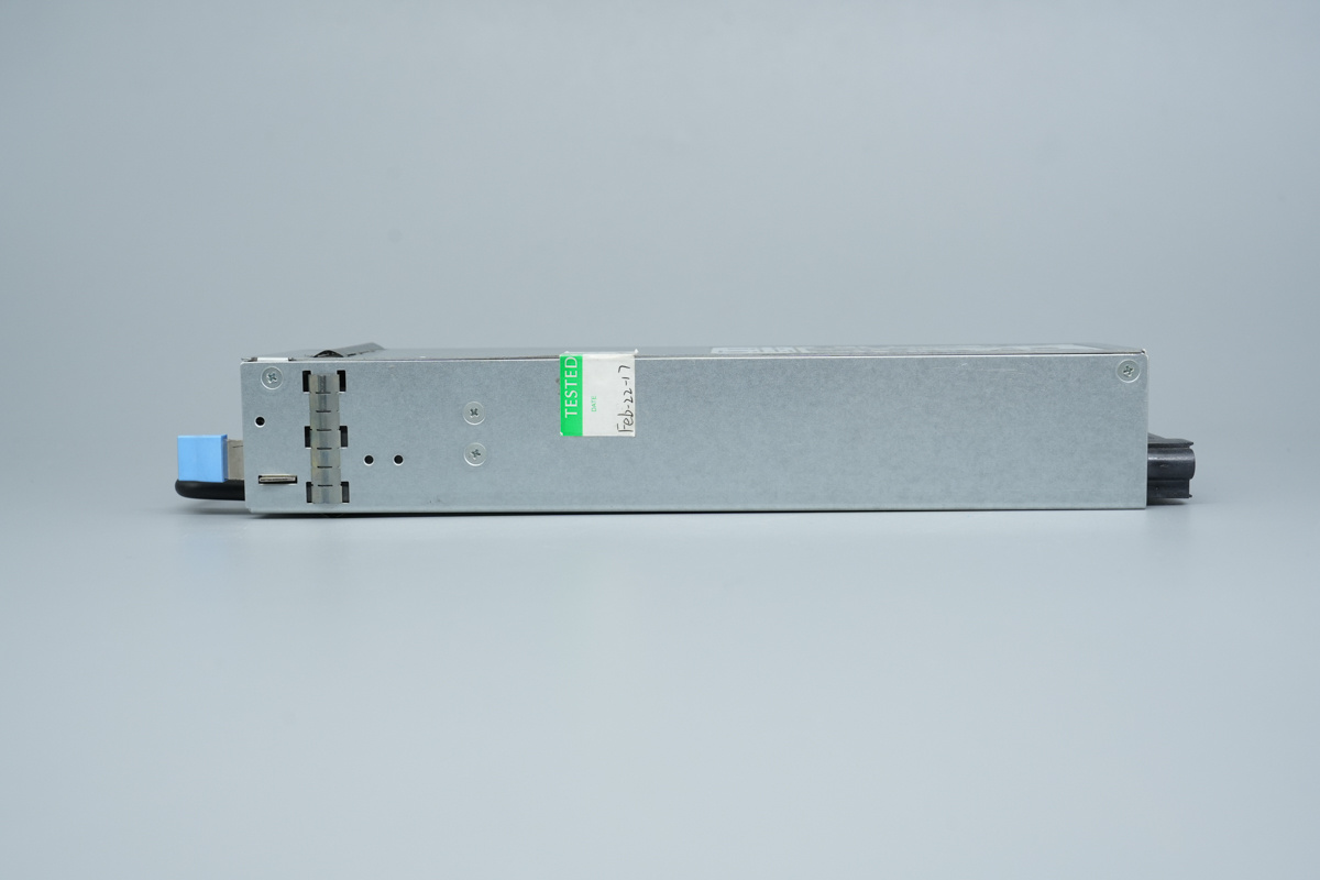
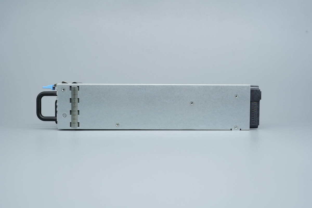
The side of the chassis is secured with screws and also features a metal grounding spring tab.
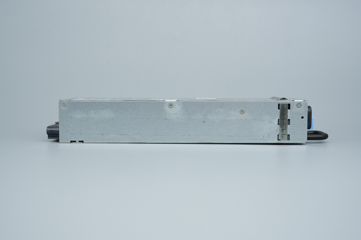
The opposite side is also secured with screws and equipped with a grounding spring tab.
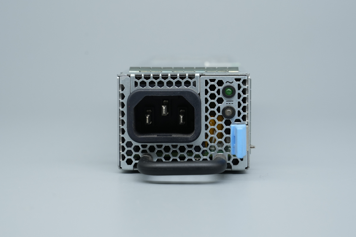
This is the AC power socket, integrated handle, LED indicators, and locking latch.
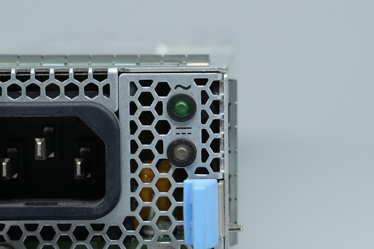
The LED indicators are used to indicate the power supply status.
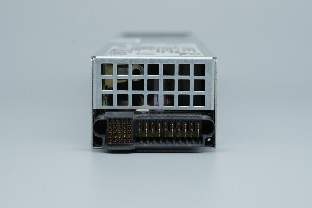
The output end is equipped with a ventilation grille and a connector.
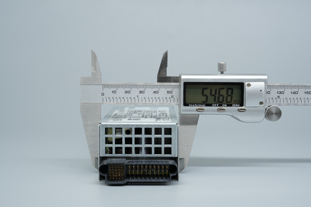
The width of the unit is about 54.7mm (2.154 inches).
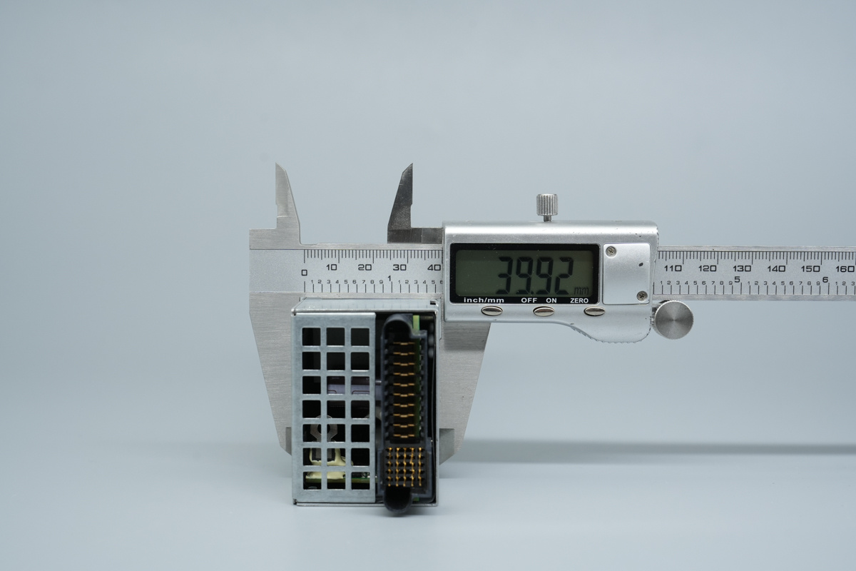
The thickness of the unit is about 39.9mm (1.571 inches).
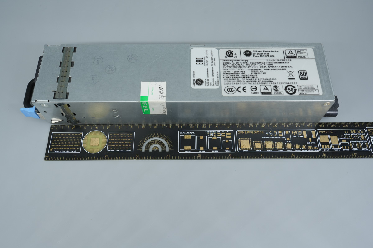
The length of the unit is about 228mm (8.976 inches).
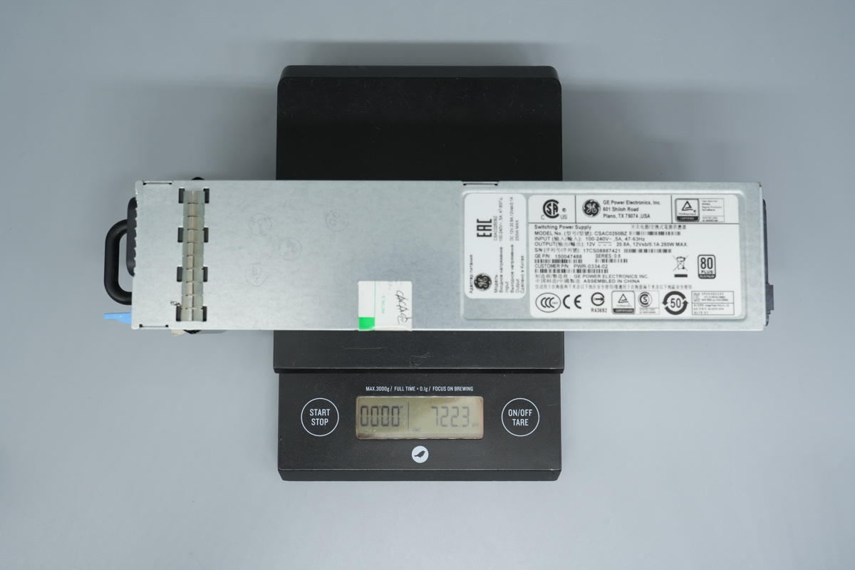
The weight is about 722g (25.47 oz).
Teardown
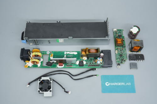
With the exterior tour of the GE server power supply finished, it’s time to break it open and see what’s inside. Let’s take a look at the design and components.
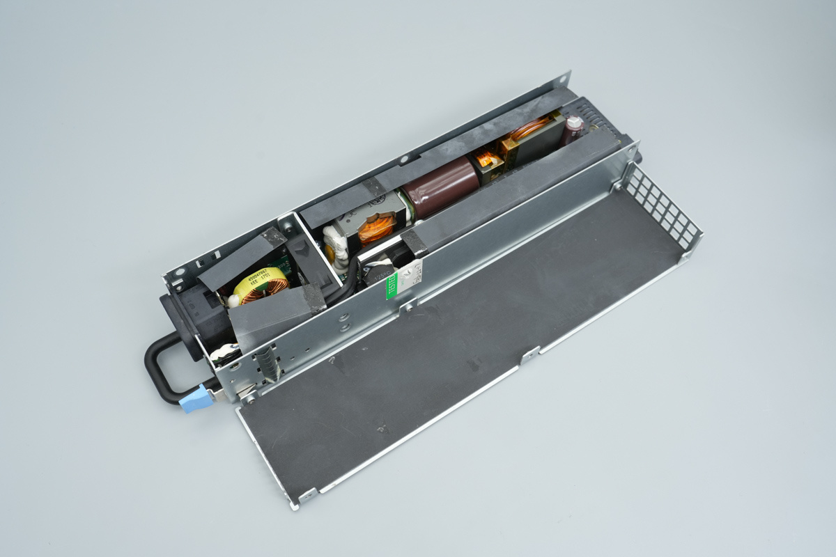
Unscrew the securing screws and remove the power supply chassis.
Mylar insulation sheets are placed between the PCBA and the chassis.
Remove the securing screws and extract the PCBA from the chassis.
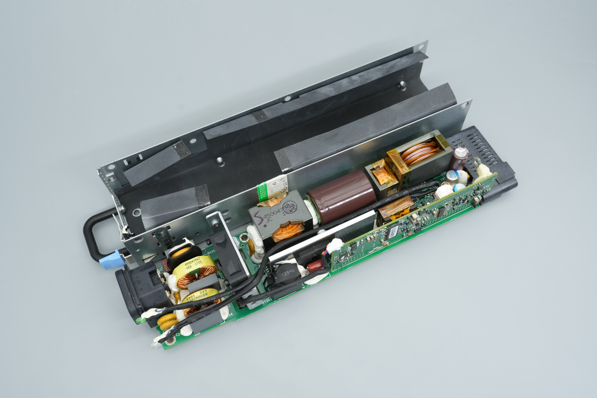
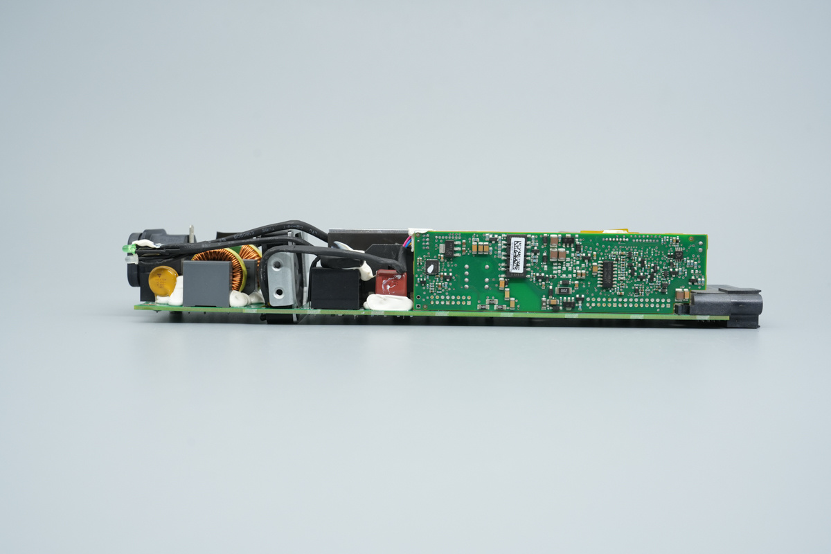
The PCBA features a long, narrow design, with LED indicator light wires insulated with heat-shrink tubing and components reinforced with white potting compound.
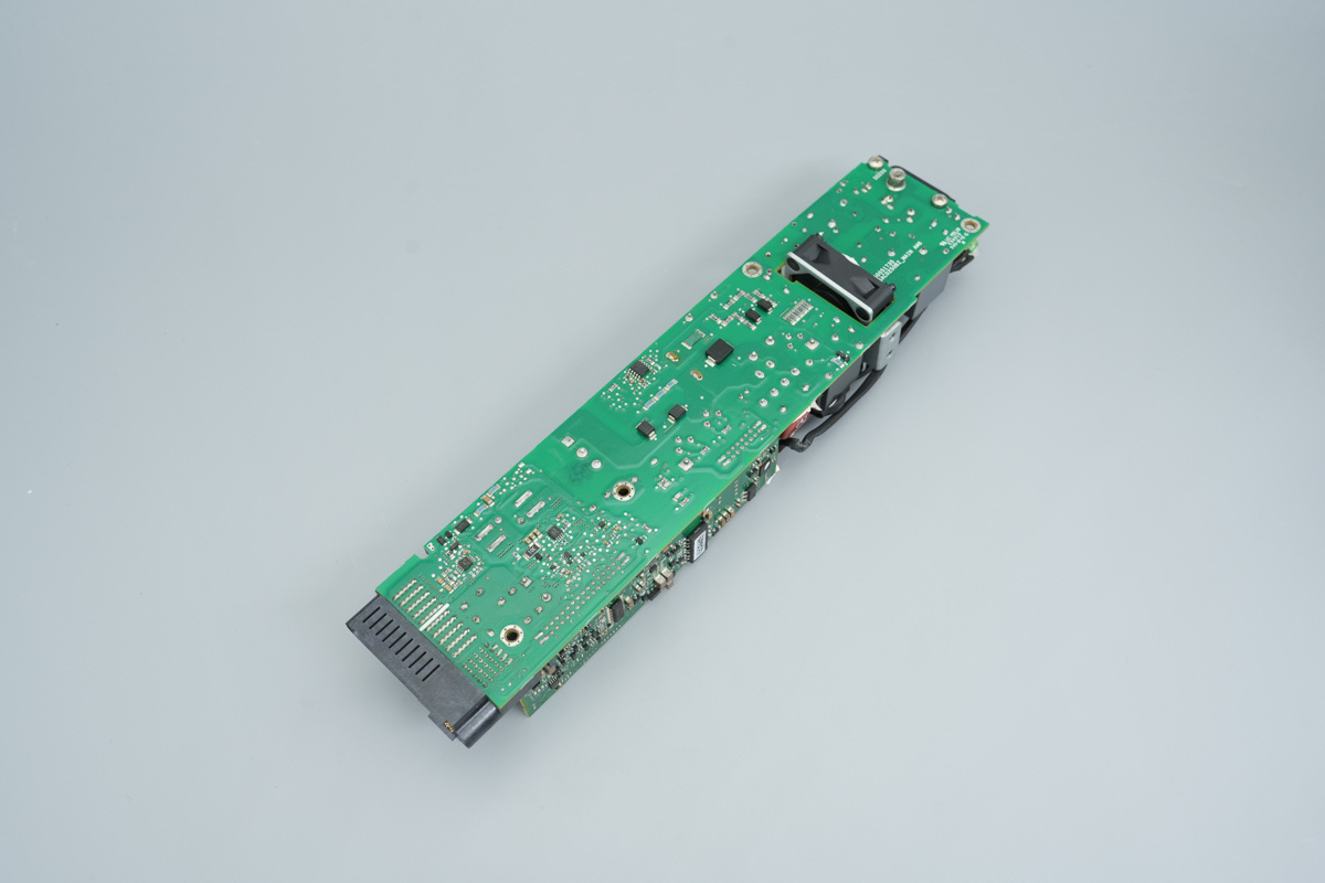
The PCBA has a cutout section beneath the cooling fan to minimize its thickness.
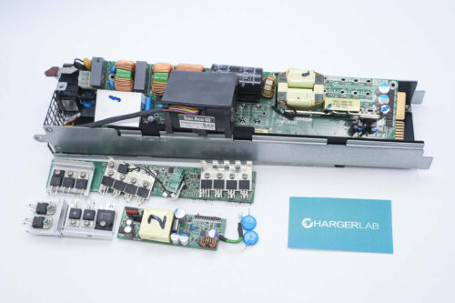
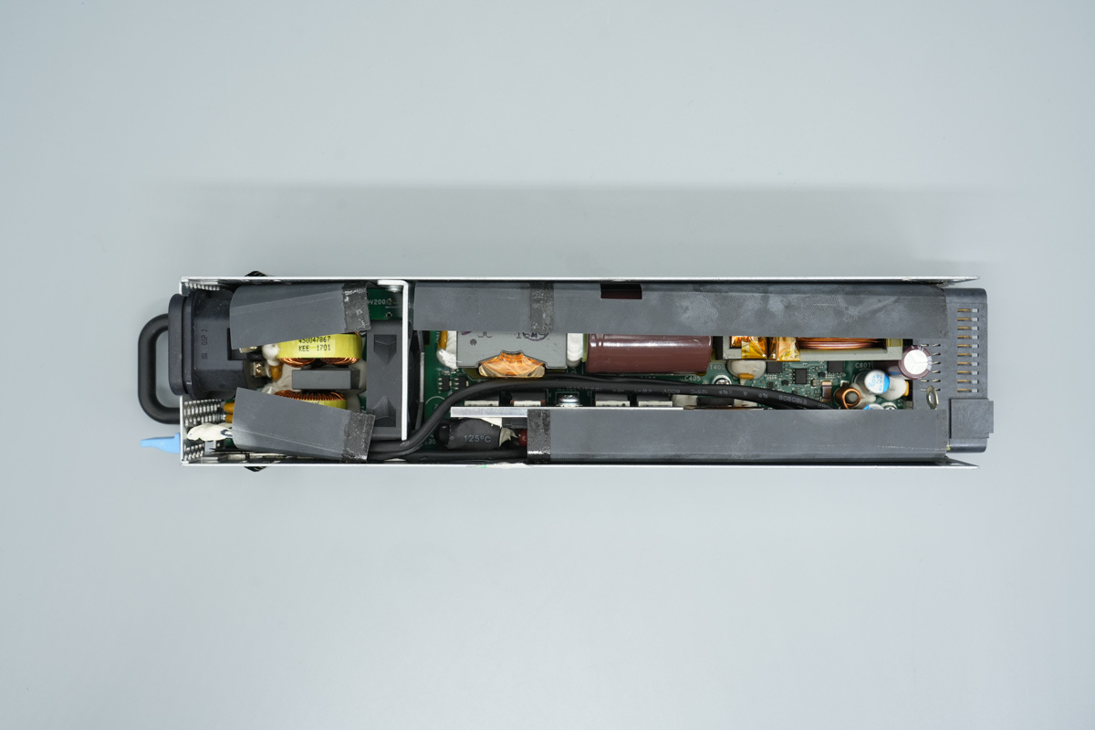
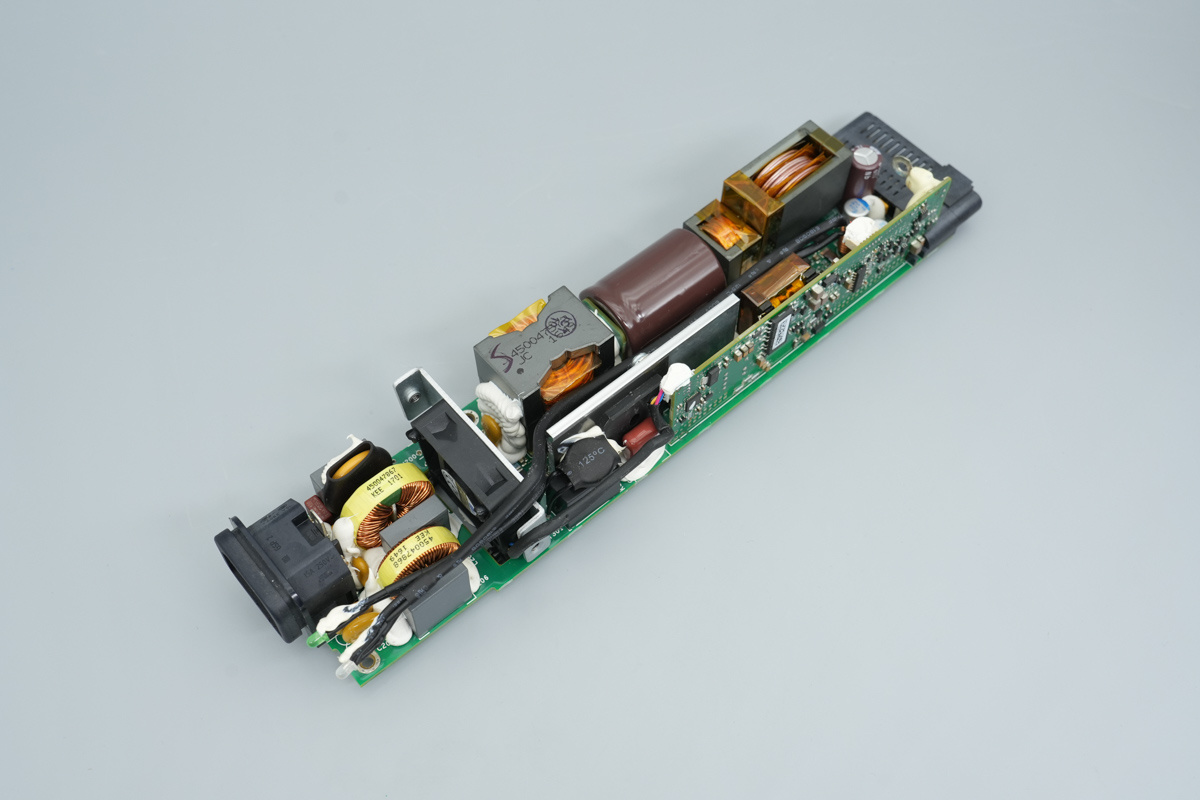
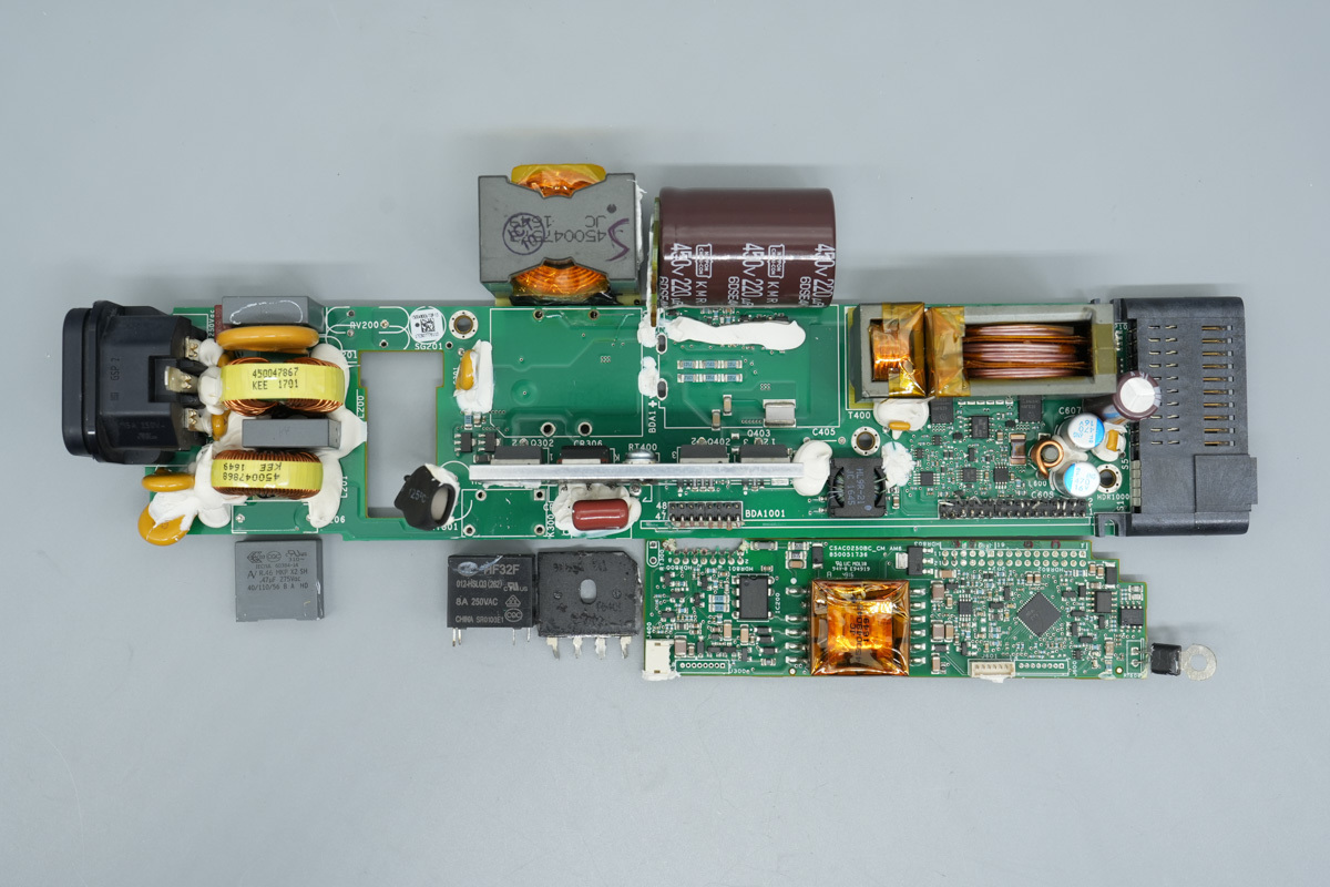
Looking at the front of the PCBA, the right side houses the AC input, including the socket, fuse, Y-caps, varistor, common-mode chokes, and safety X2 caps. On the left is the cooling fan, adjacent to a heatsink that dissipates heat for the rectifier bridge, PFC MOSFETs, PFC rectifier MOSFETs, and LLC MOSFETs.
Beneath the heatsink are the PFC boost choke and high-voltage filter cap. To the left lie the resonant choke and transformer. The control PCB and standby power transformer are located at the top. The output end on the left includes filter caps, a filtering choke, and the output connector.
The back of the PCBA features the PFC controller, current sensing resistors, bypass diode, voltage comparator, and gate drivers, among other components.
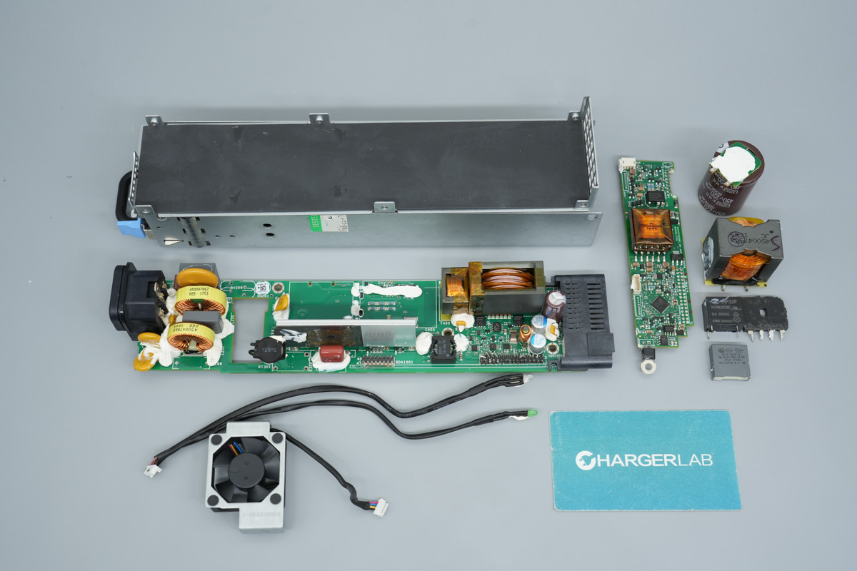
The safety X2 cap, relay, rectifier bridge, PFC boost choke, high-voltage filter cap, and control PCB have been desoldered and removed to continue the teardown.
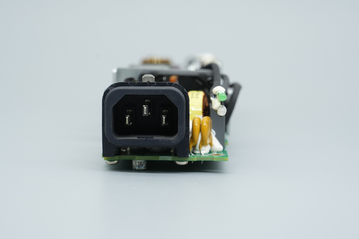
The input end features an AC socket, Y-caps, and LED indicators.
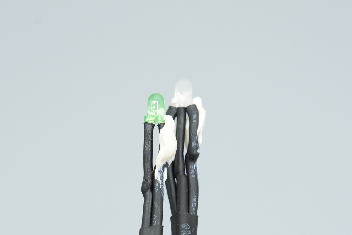
The LED indicator pins are insulated using heat-shrink tubing.
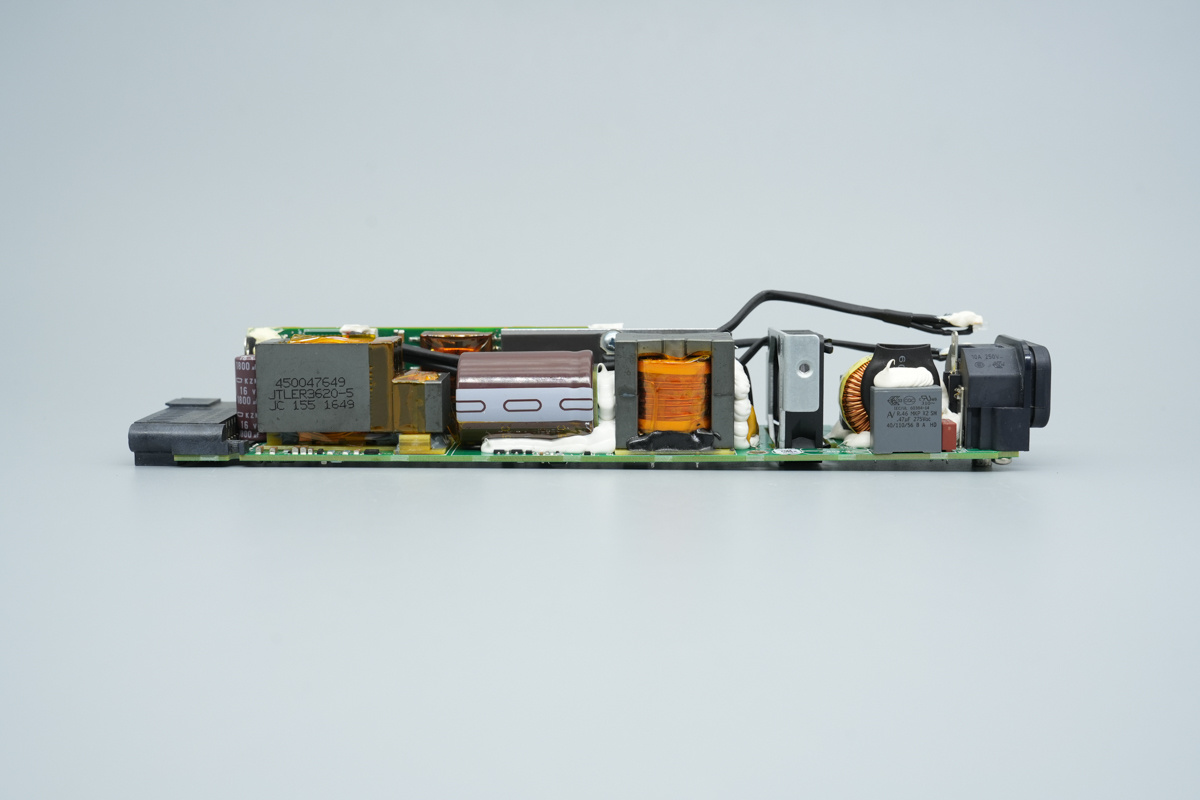
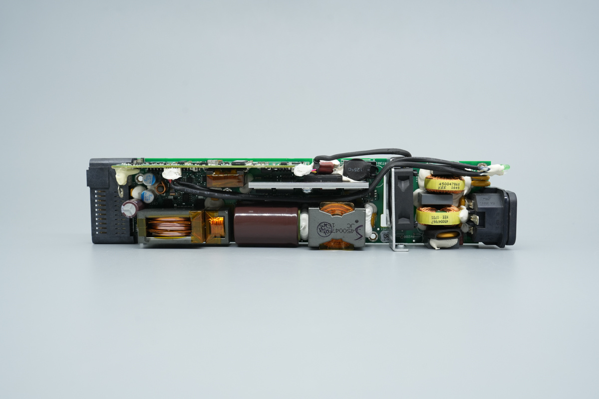
The side houses a safety X2 cap, a PFC boost choke, a high-voltage filter cap, a resonant choke, and an LLC transformer.
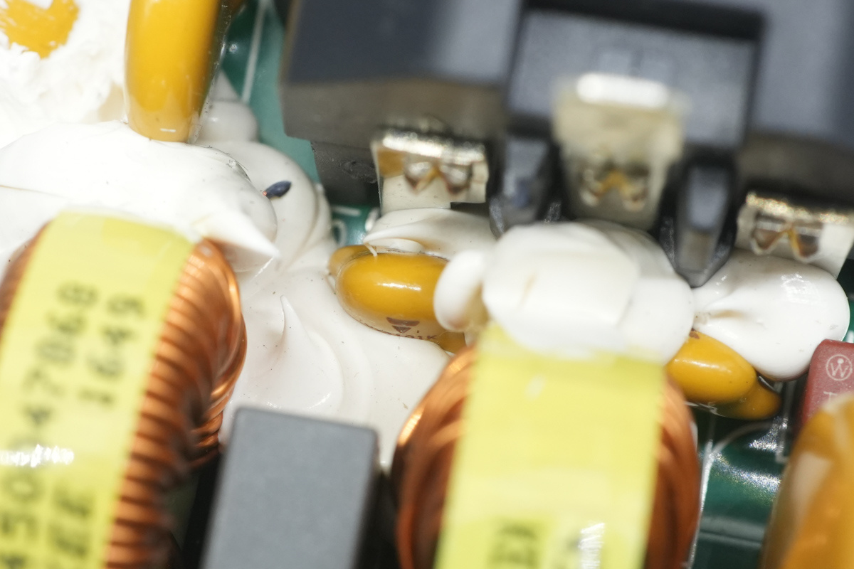
The yellow Y-cap is from Vishay.
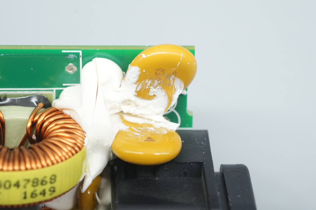
The Y-capacitor reinforced with white potting compound at the power socket.
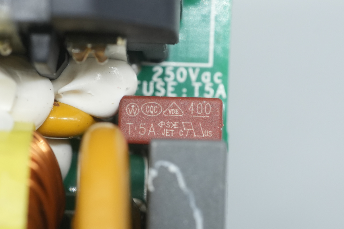
The fuse is supplied by Littelfuse, spec 5A.
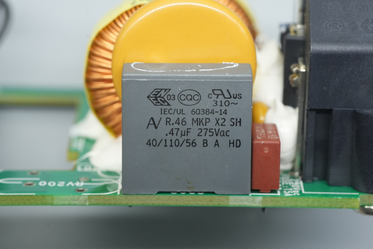
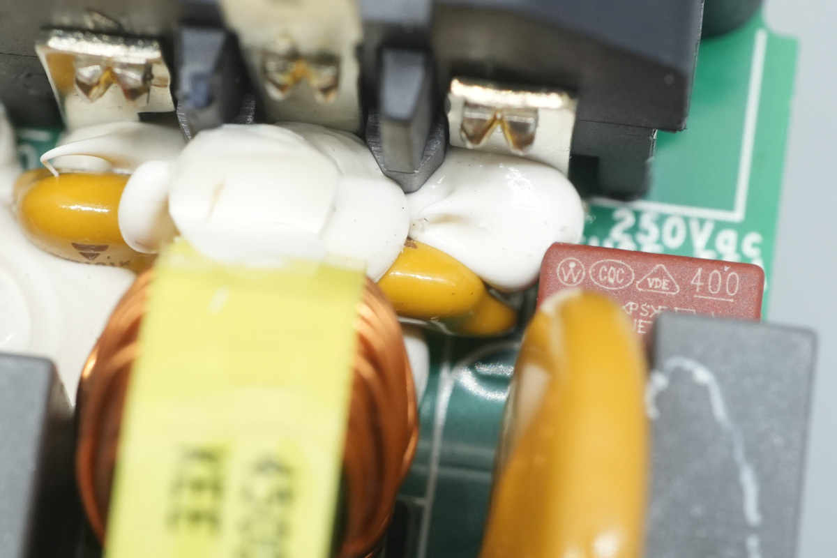
The safety X2 cap, spec 0.47μF.
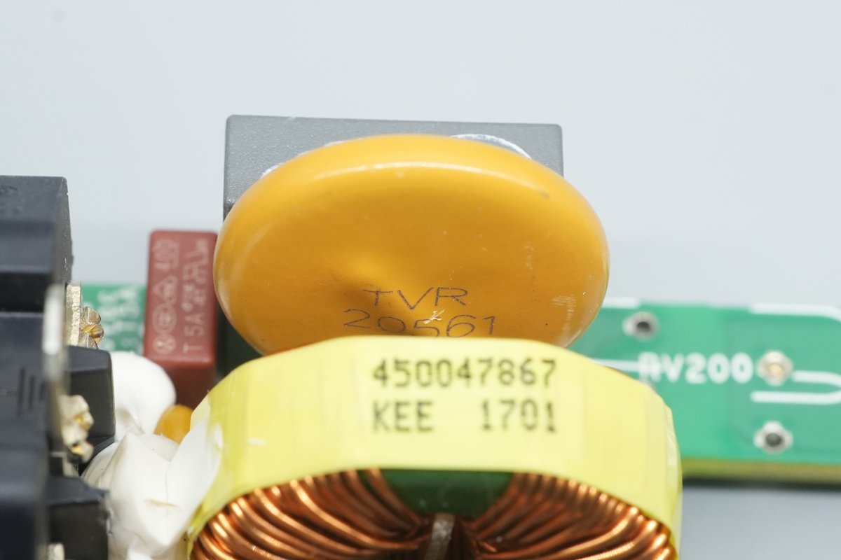
The varistor, model TVR20561, is utilized to suppress overvoltage surges.
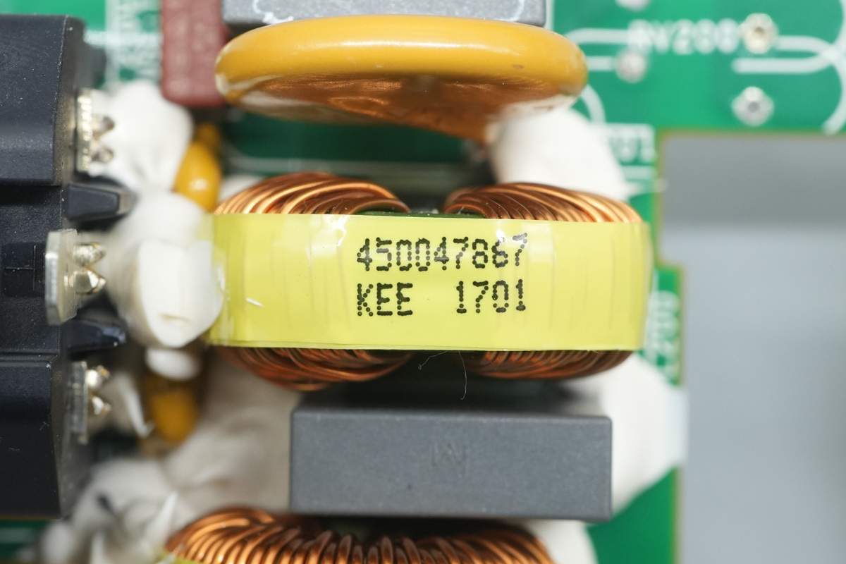
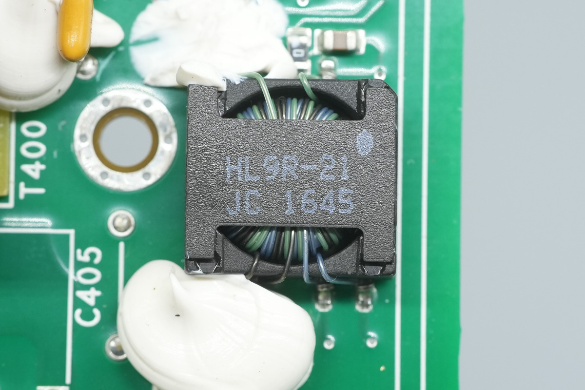
The common-mode choke is wound with enameled wire and features a bakelite base for insulation.
The safety X2 cap is reinforced with white potting compound.
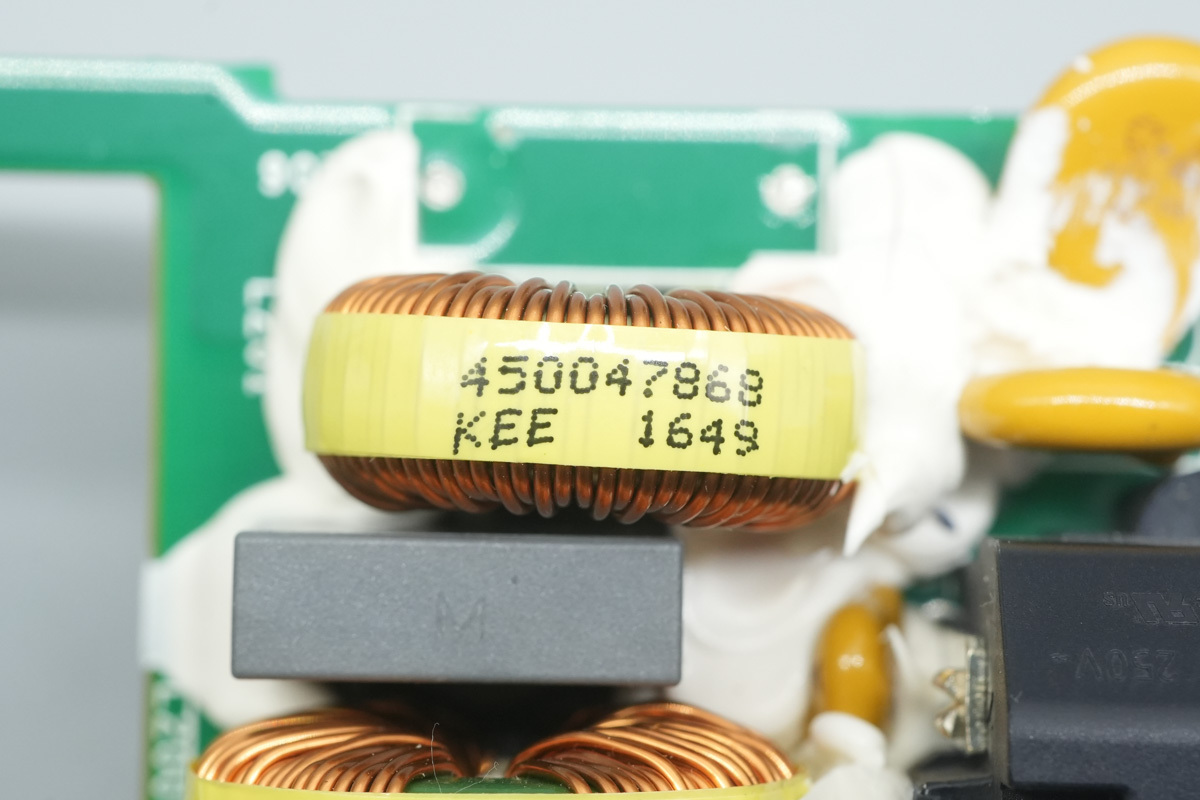
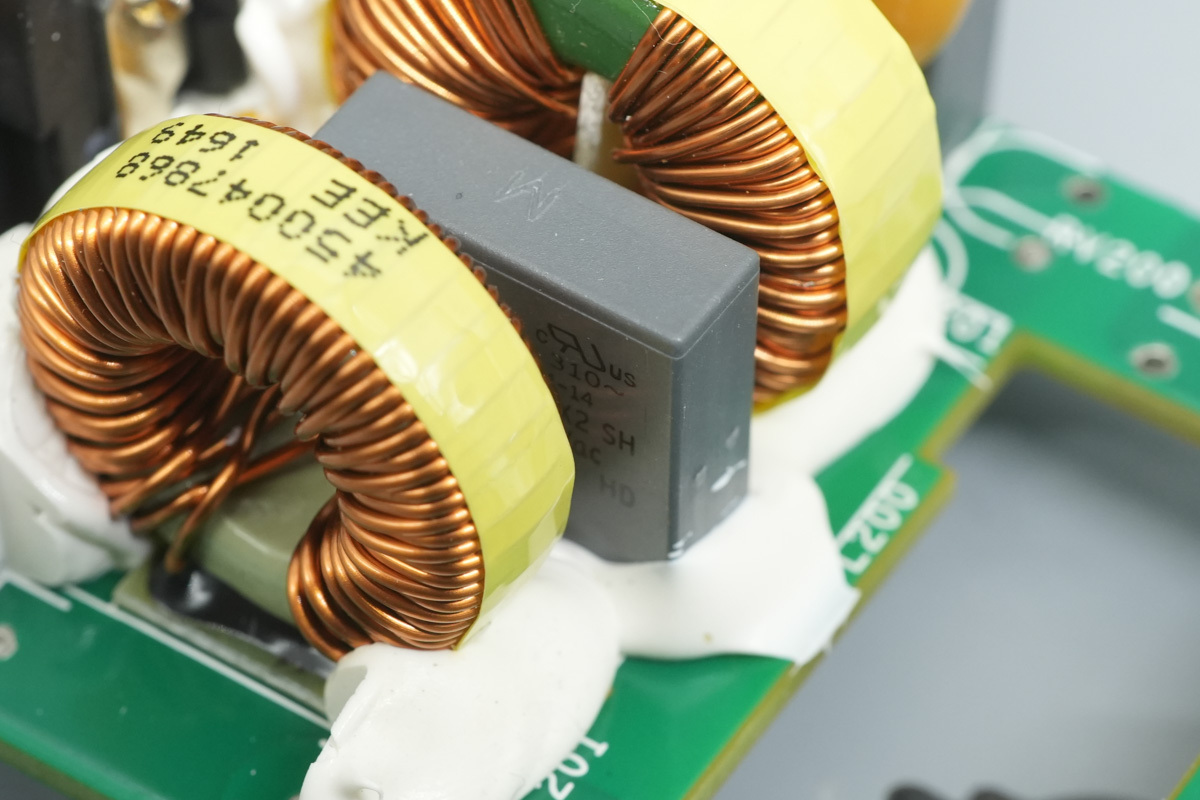
Another common-mode choke.
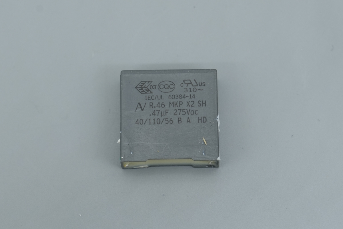
The safety X2 cap, spec 0.47μF.
The two yellow Y-caps are from Vishay.
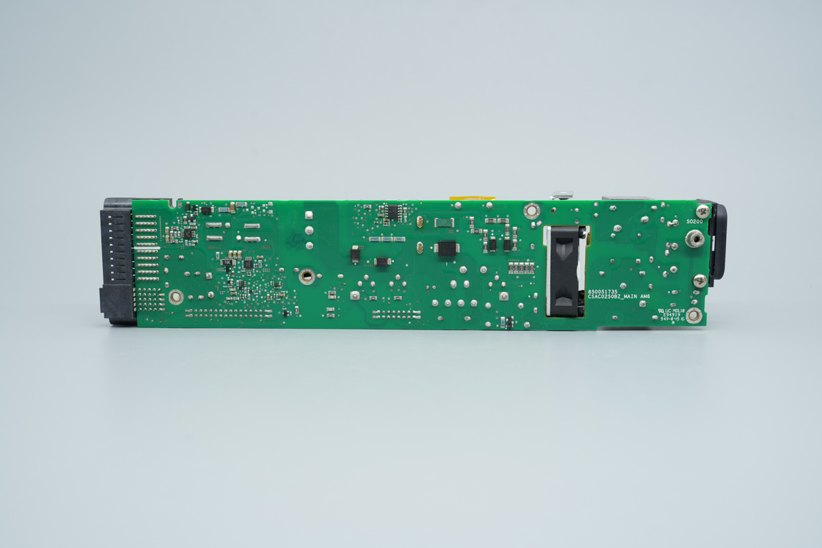
The opposite side houses the safety X2 cap, rectifier bridge, relay, film filtering cap, and the control PCB.
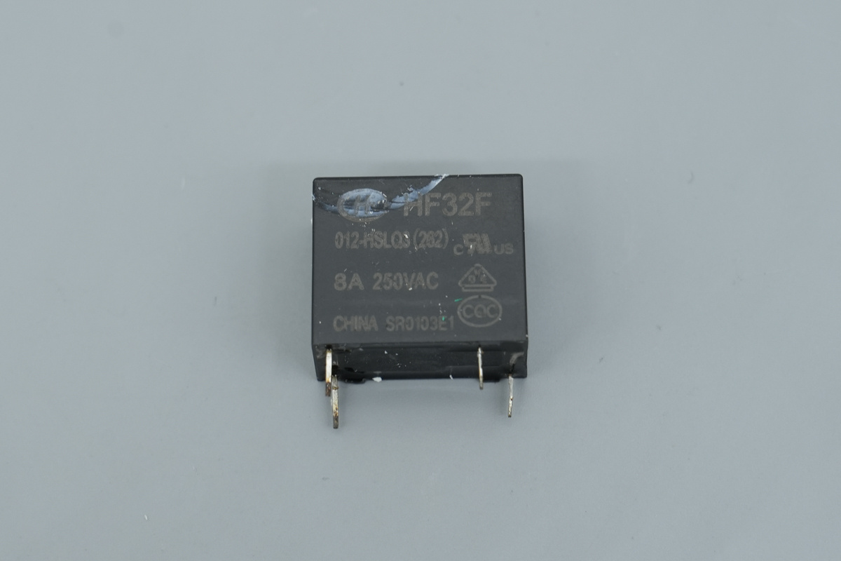
The relay is from Hongfa, model HF32F/012-HSLQ3. This is an ultra-miniature, medium-power relay featuring a single normally-open contact set with a capacity of 8A 250V. It utilizes a 12V sensitive coil.
The startup resistor is insulated with heat-shrink tubing.
The rectifier bridge is secured to the heatsink.
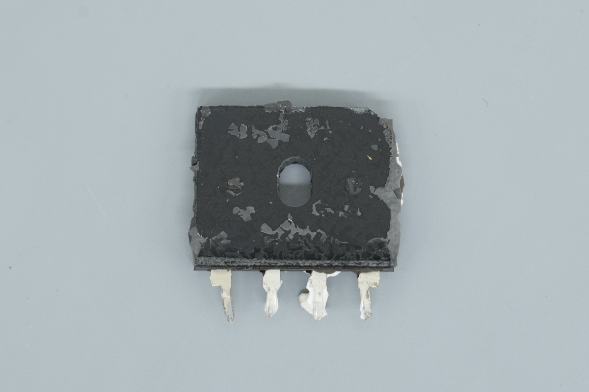
The markings on the rectifier bridge are obscured by thermal interface material, rendering them illegible.
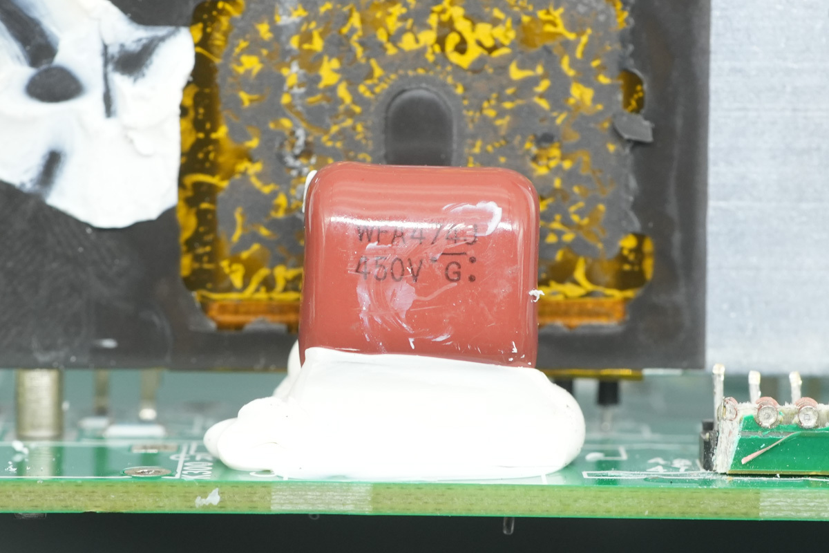
The film filtering cap, 0.47μF, 450V.
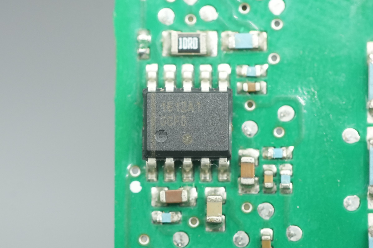
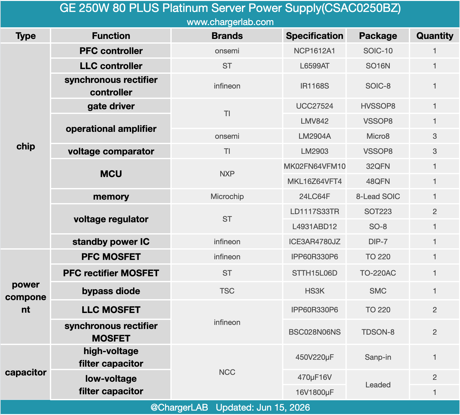
The PFC controller is from onsemi, model NCP1612A1. It is an enhanced critical conduction mode PFC controller featuring a PFC OK signal, rapid overvoltage protection, and soft overvoltage protection, housed in a SOIC-10 package.
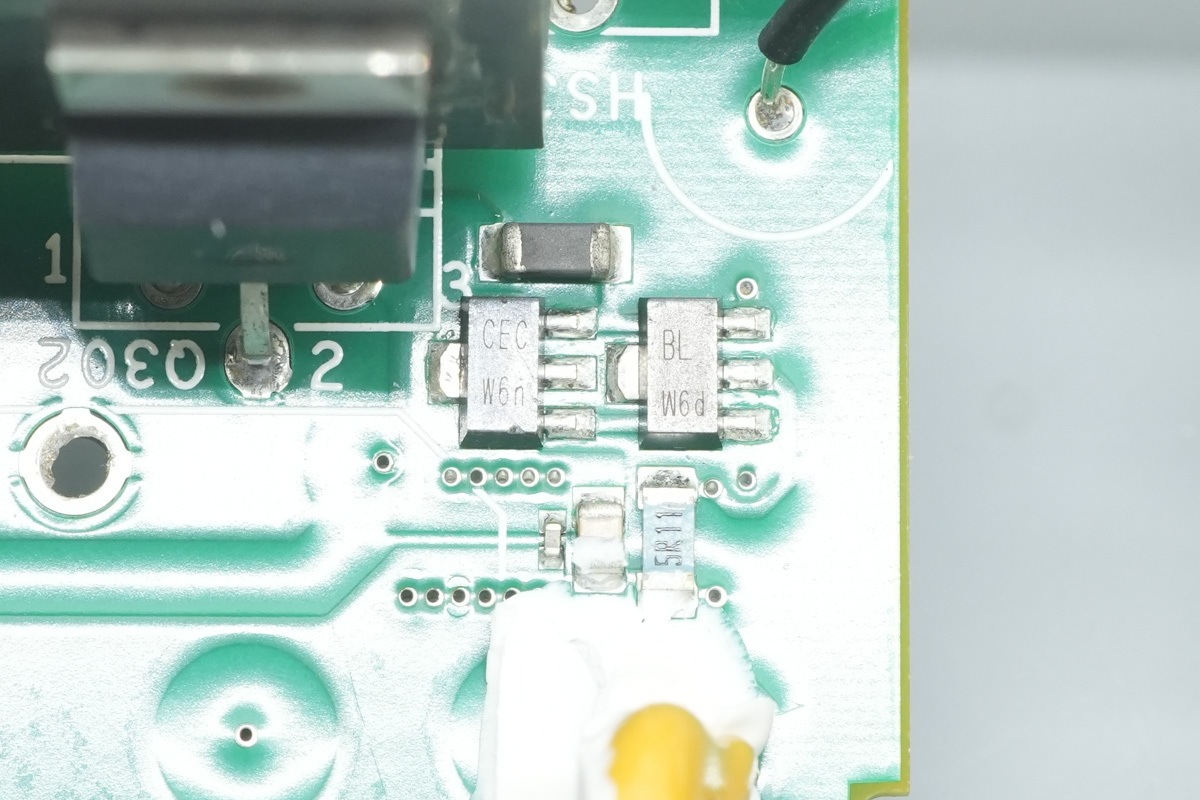
Two SMD transistors are utilized for driving the PFC MOSFETs.
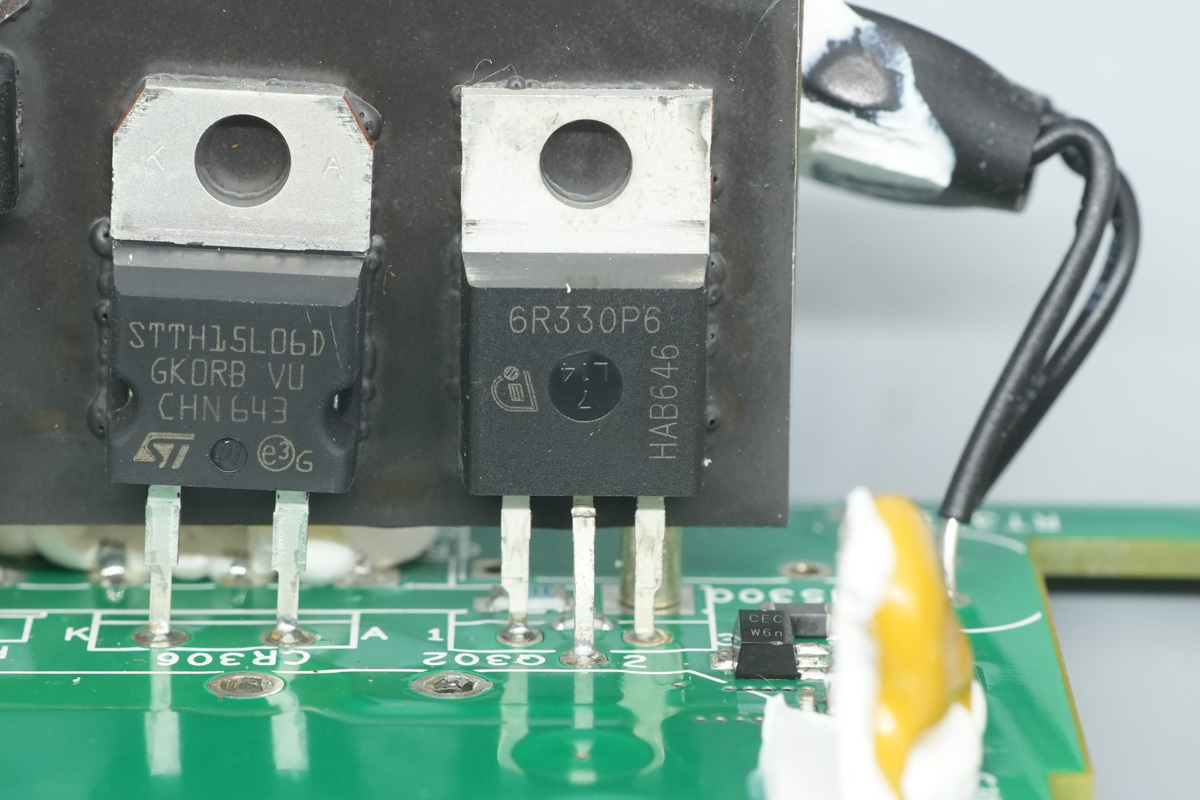
The PFC MOSFET is from Infineon, model IPP60R330P6, marked 6R330P6, specially the CoolMOS P6 series, NMOS, 650V and 330mΩ, and is housed in a TO-220 package.
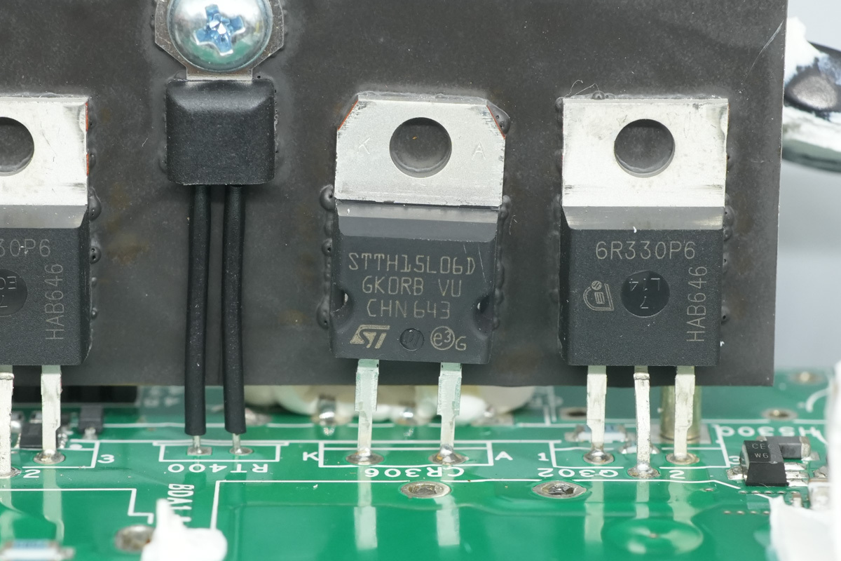
The PFC rectifier MOSFET is from ST, model STTH15L06D. It is an ultrafast diode rated at 600V, 15A, and is housed in a TO-220AC package.
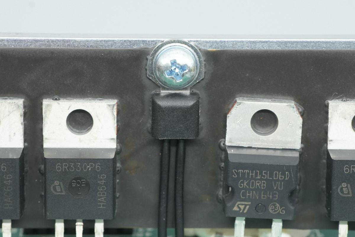
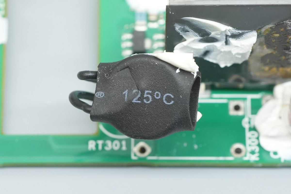
A thermistor is utilized to monitor the temperature of the heatsink.
The PFC boost choke is wound with Litz wire.
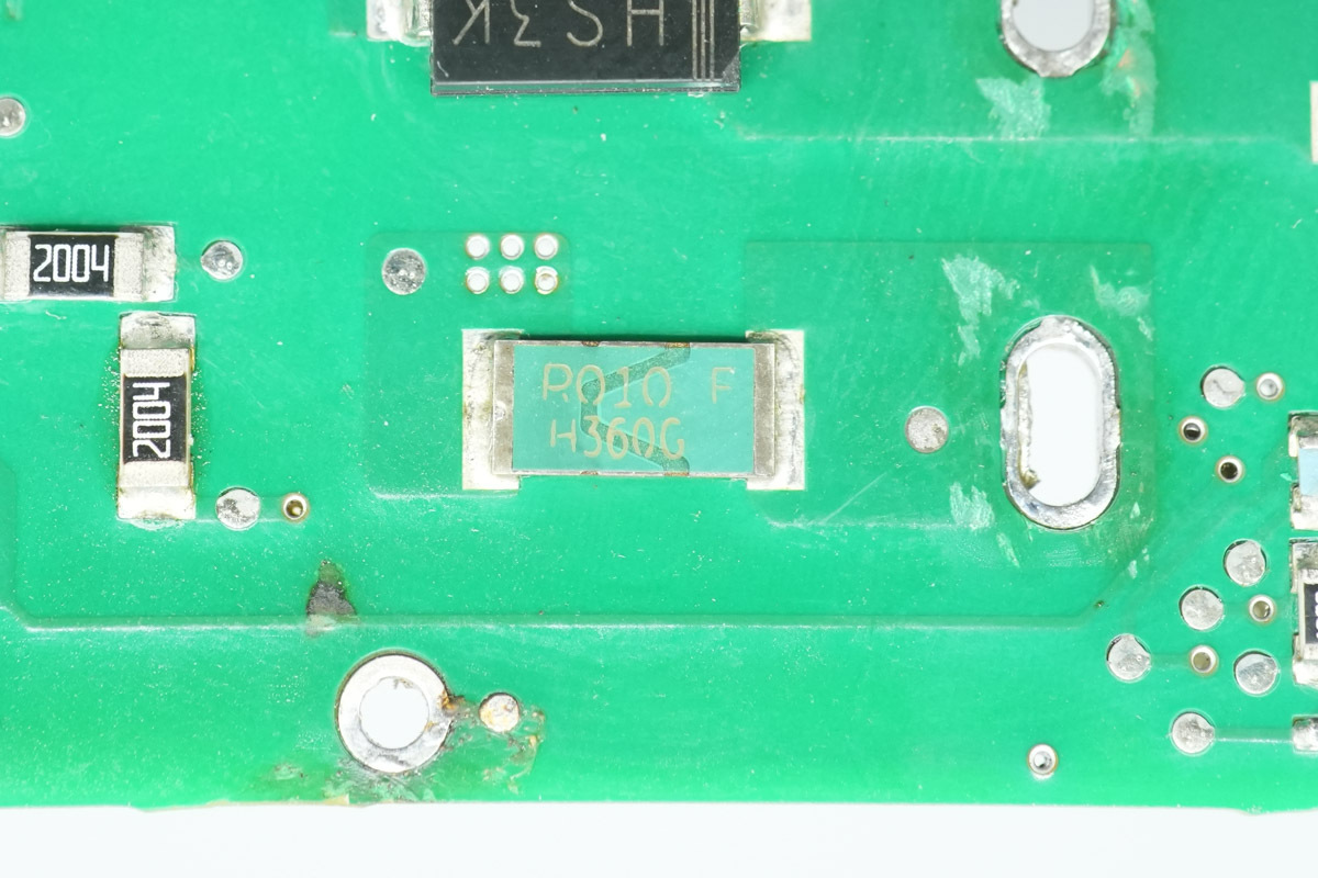
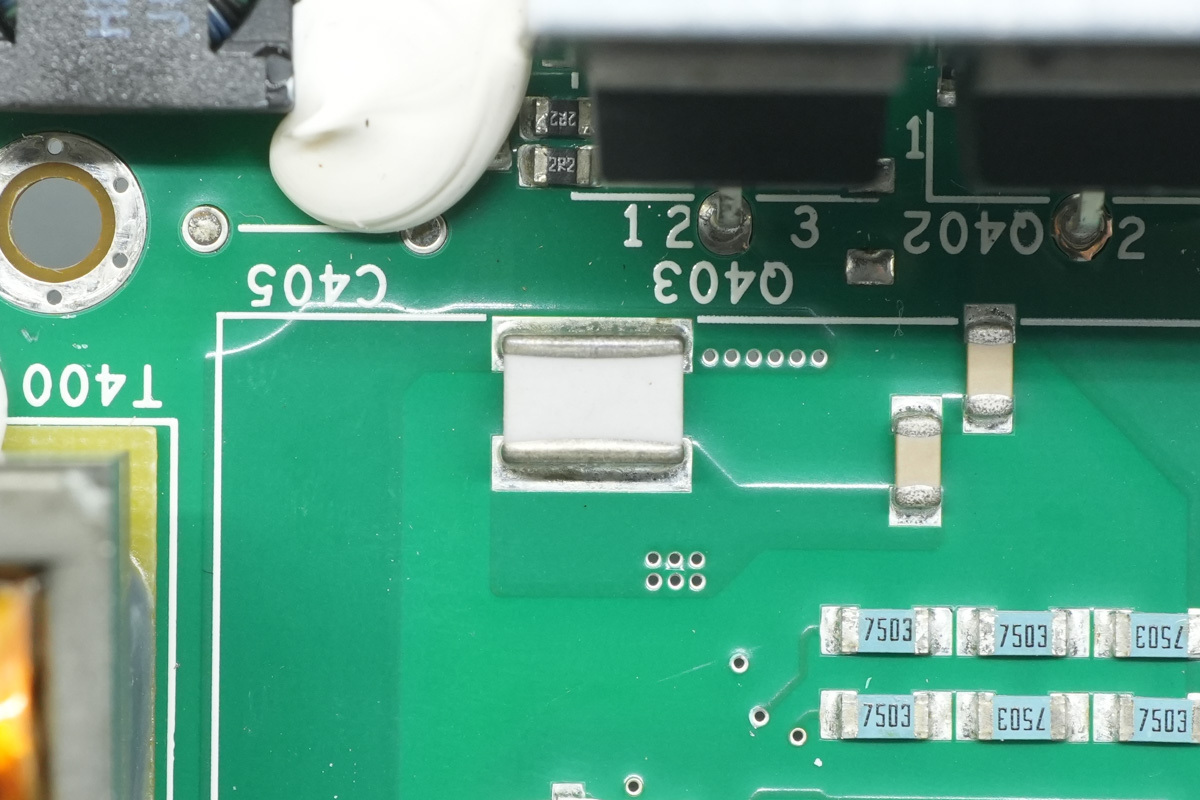
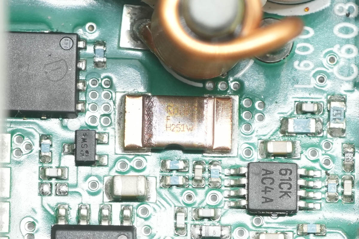
A 10mΩ current sensing resistor is utilized to monitor the current of the PFC MOSFET.
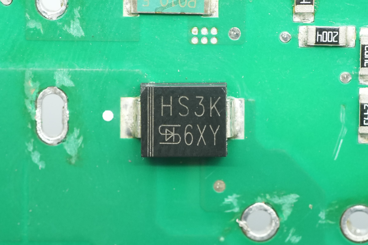
The bypass diode is from TSC, model HS3K. It is a fast recovery diode rated at 800V, 3A, and housed in an SMC package.
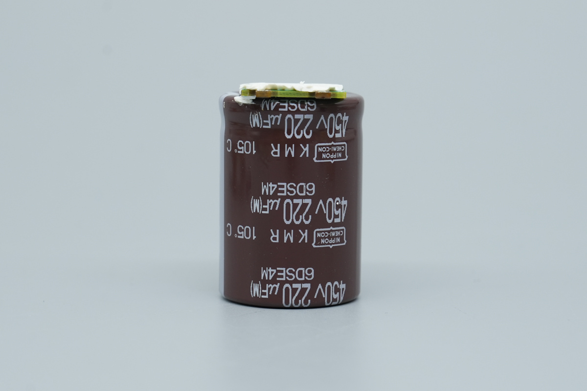
The high-voltage filter cap is from NCC, belonging to the KMR series of snap-in aluminum electrolytic caps, spec 450V, 220μF.
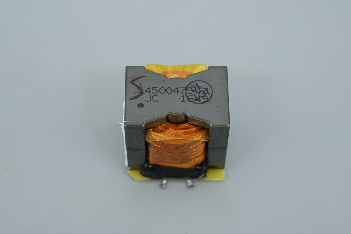
This is the isolation transformer utilized for driving the LLC MOSFETs.
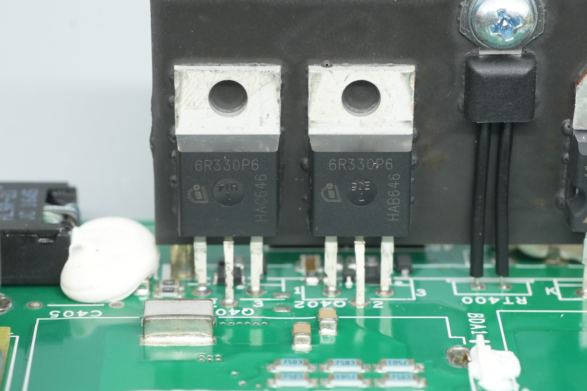
The two LLC MOSFETs are from Infineon, model IPP60R330P6, identical to the PFC MOSFET model.
The LLC resonant cap features NPO construction.
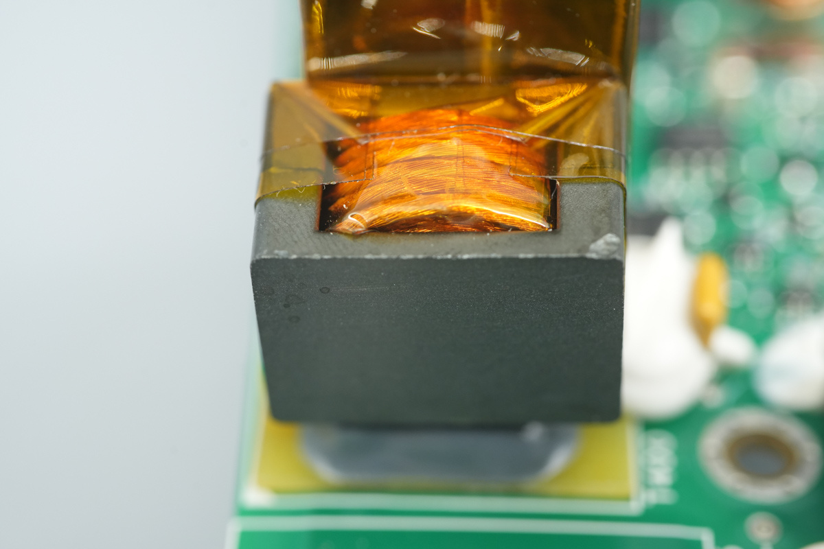
The resonant choke is wound with Litz wire and features an insulating bakelite base.
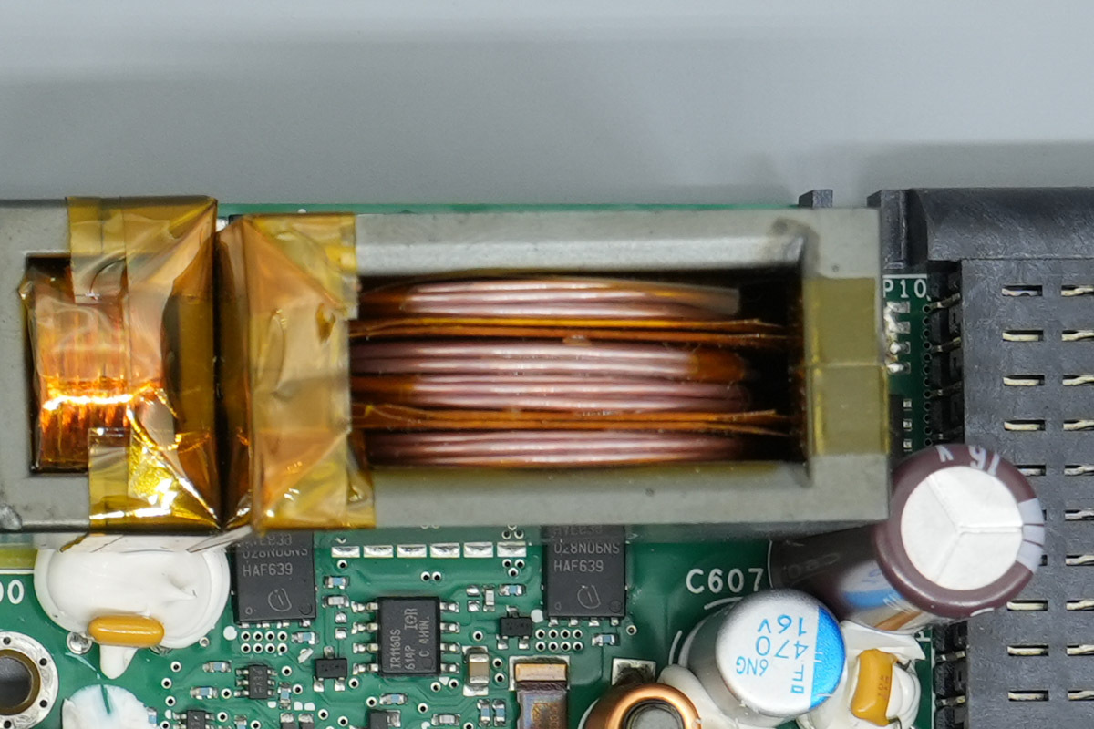
The transformer features primary windings made of insulated wire, with copper strips soldered onto the secondary side.
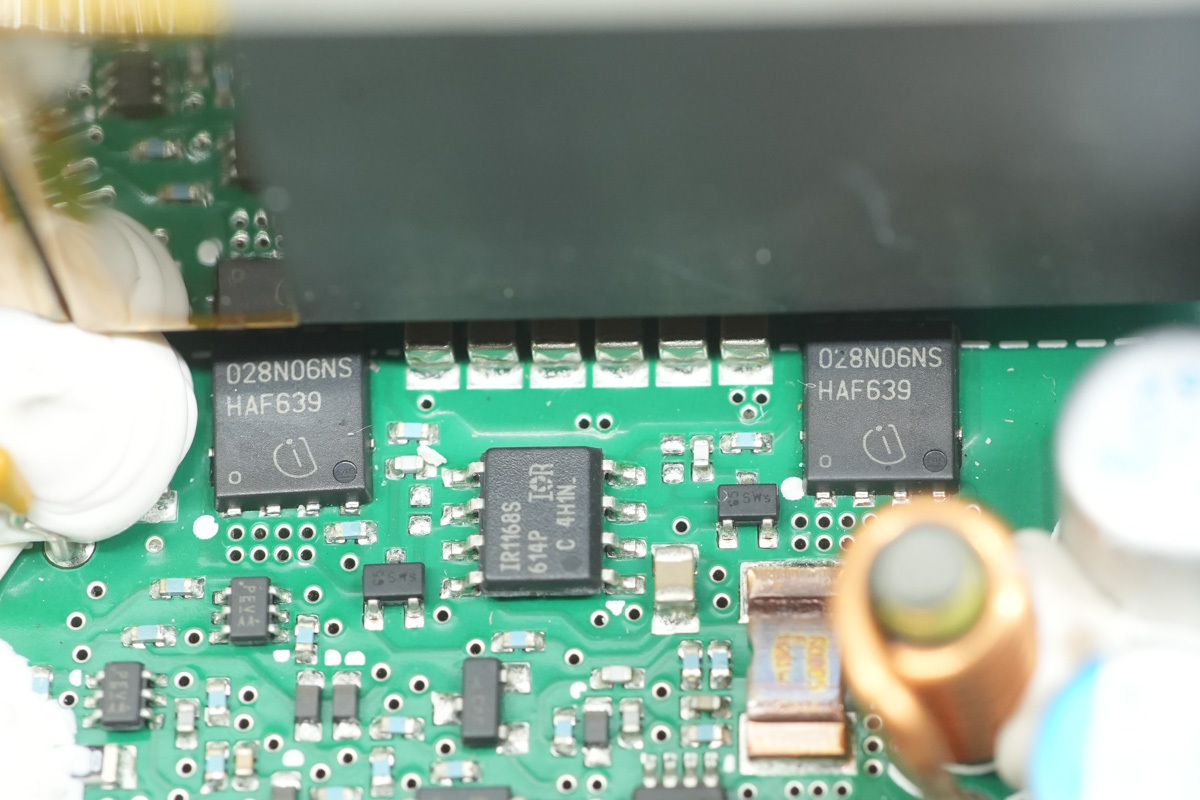
The synchronous rectifier MOSFETs are from Infineon, model BSC028N06NS, NMOS, 60V and 2.8mΩ, and are housed in a TDSON-8 package.
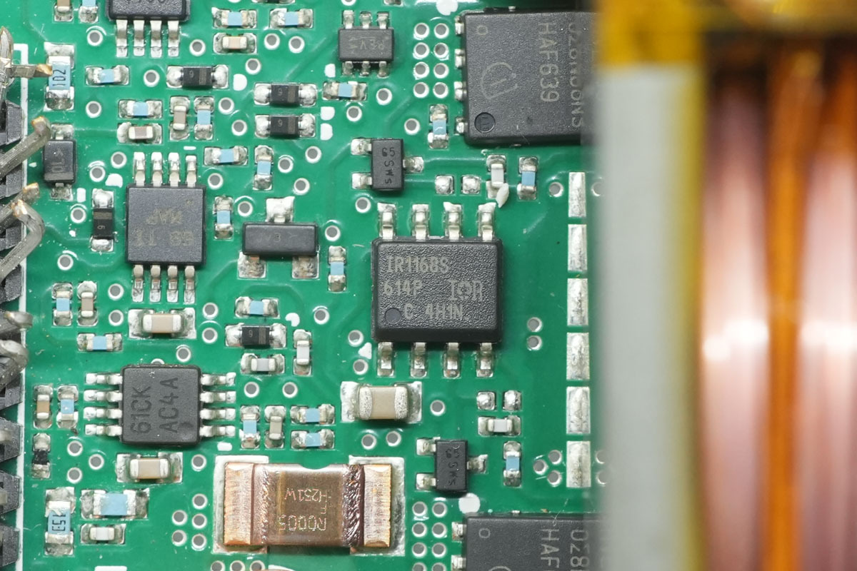
The synchronous rectifier controller is from Infineon, model IR1168S, a dual-channel smart rectifier driver designed for LLC half-bridge applications. It supports switching frequencies up to 500 kHz and is housed in a SOIC-8 package.
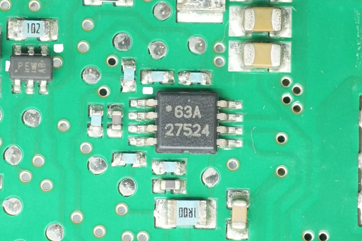
The gate driver is from TI, model UCC27524, is a dual-channel 5A high-speed low-side gate driver with negative input voltage capability, supporting a single supply of 4.5-18V, and is packaged in an HVSSOP8 package.
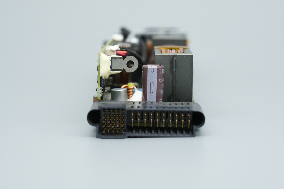
The output end features connectors and filter capacitors.
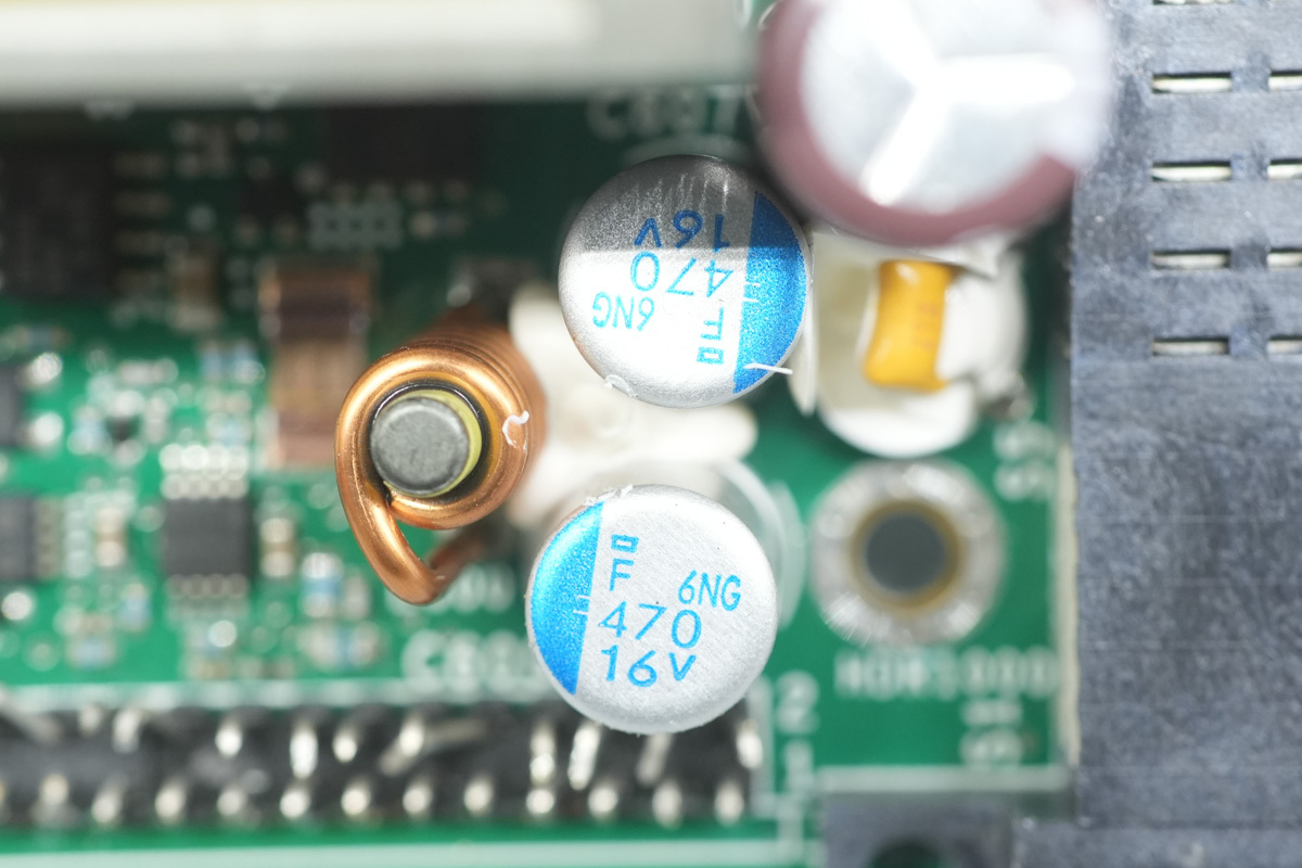
The filter caps are from NCC, specially the PSF series conductive polymer aluminum solid electrolytic caps, spec 470μF and 16V.
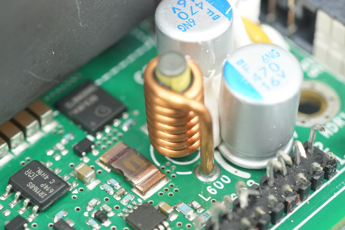
This is the filter choke.
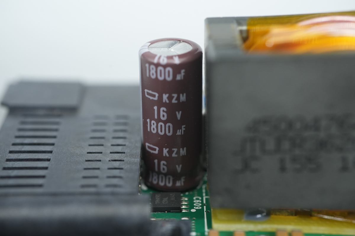
The filter capacitors are from NCC, specially the KZM series, long-life, low-impedance aluminum electrolytic caps, spec 16V and 1800μF.
The output current sensing resistor, spec 0.5mΩ.
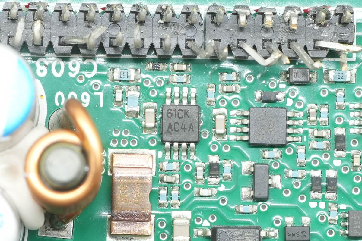
The operational amplifier is from TI, model LMV842, marked AC4A, It is a dual-channel, CMOS-input, RRIO, wide-supply-range operational amplifier housed in a VSSOP-8 package, utilized for output current sensing.
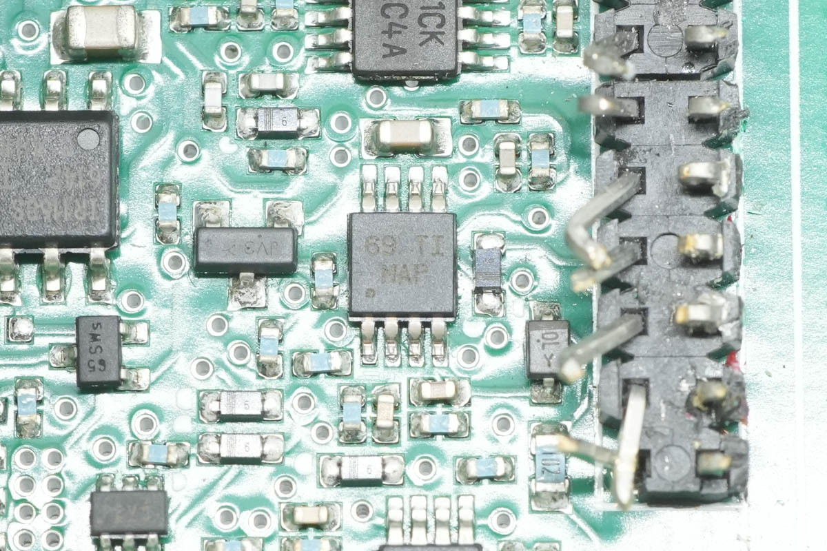
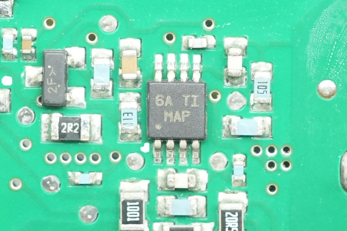
The voltage comparator is from TI, model LM2903, marked MAP, it is a general-purpose dual differential comparator housed in a VSSOP-8 package.
Another one shares the same model.
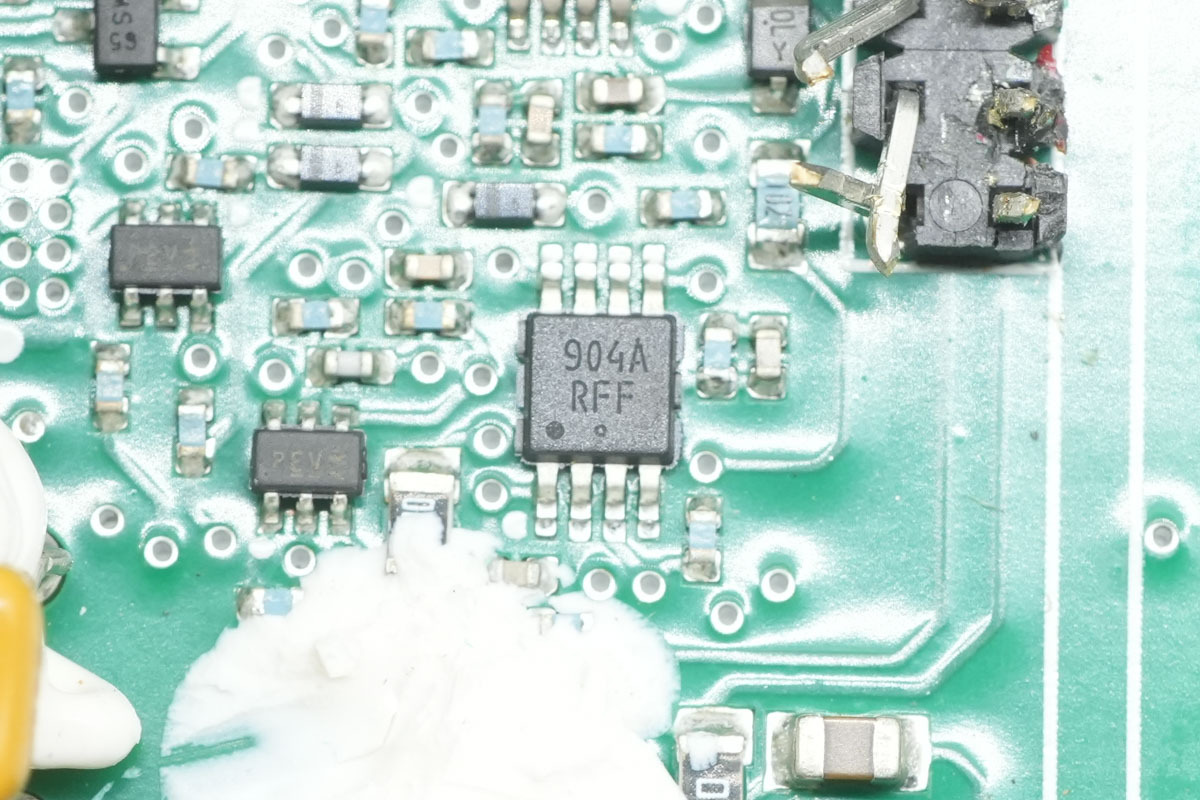
The operational amplifier is from onsemi, model LM2904A, marked 904A. It is a dual-channel, single-supply operational amplifier housed in a Micro8 package.
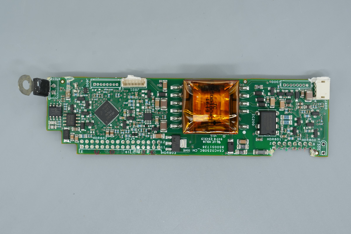
The control PCB features an MCU, memory, voltage regulator, operational amplifier, standby power transformer, and standby power IC.
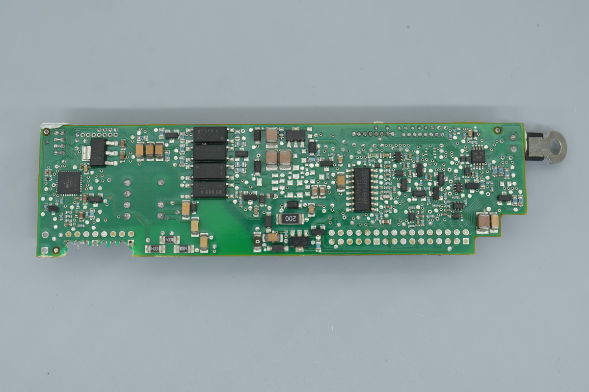
The reverse side accommodates an MCU, voltage regulator, optocouplers, an LLC controller, and a voltage comparator.
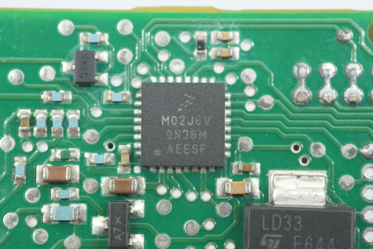
The MCU is from NXP, model MK02FN64VFM10, marked M02J6V. It features a 100MHz Arm Cortex-M4 core with DSP instructions, integrated 64KB Flash and 16KB RAM, and supports SPI, UART, and I2C interfaces. It is housed in a 32-pin QFN package.
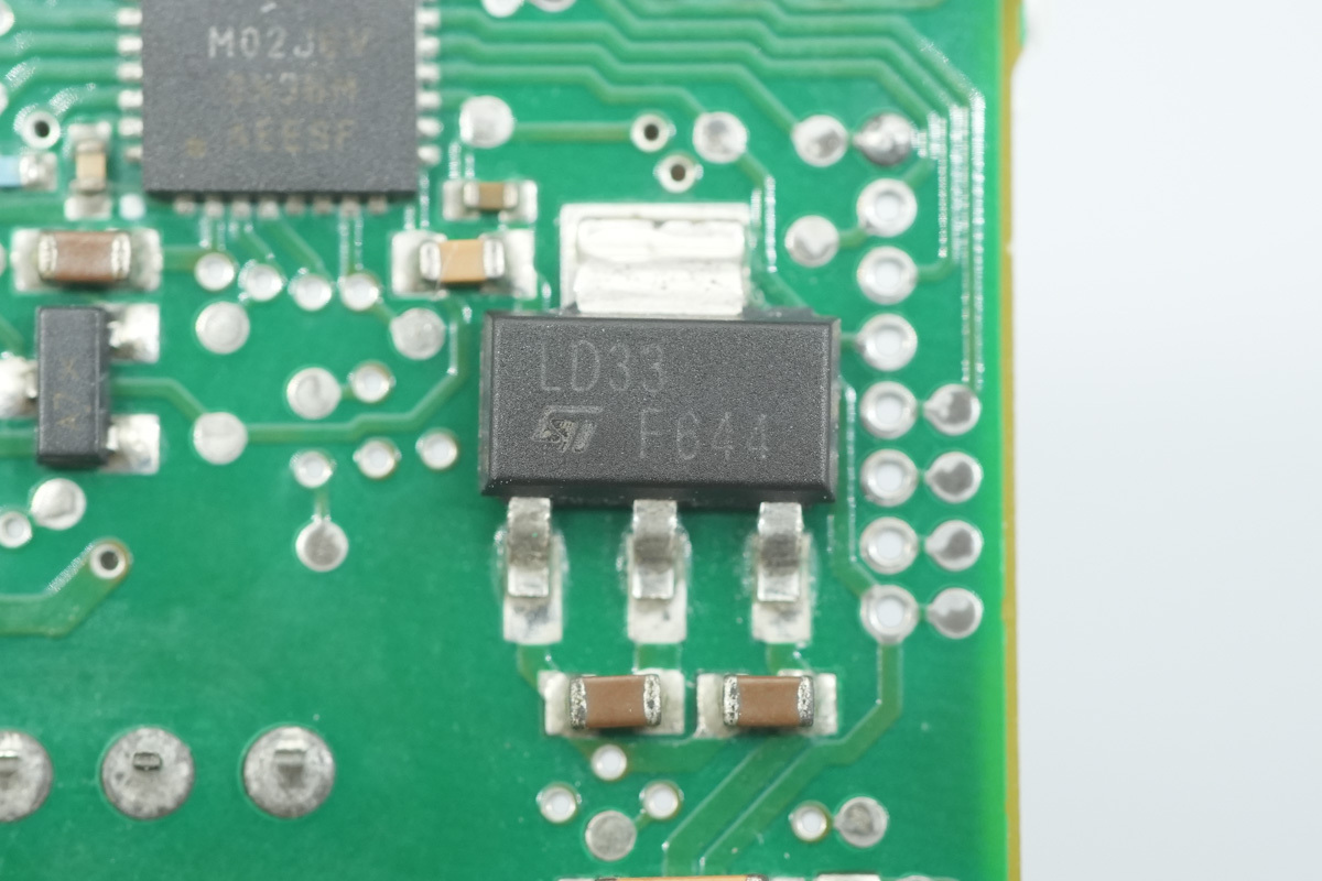
The voltage regulator powering the MCU is from ST, model LD1117S33TR, marked LD33. It supports an input voltage of up to 15V, provides a fixed 3.3V output at 800mA, and is housed in a SOT-223 package.
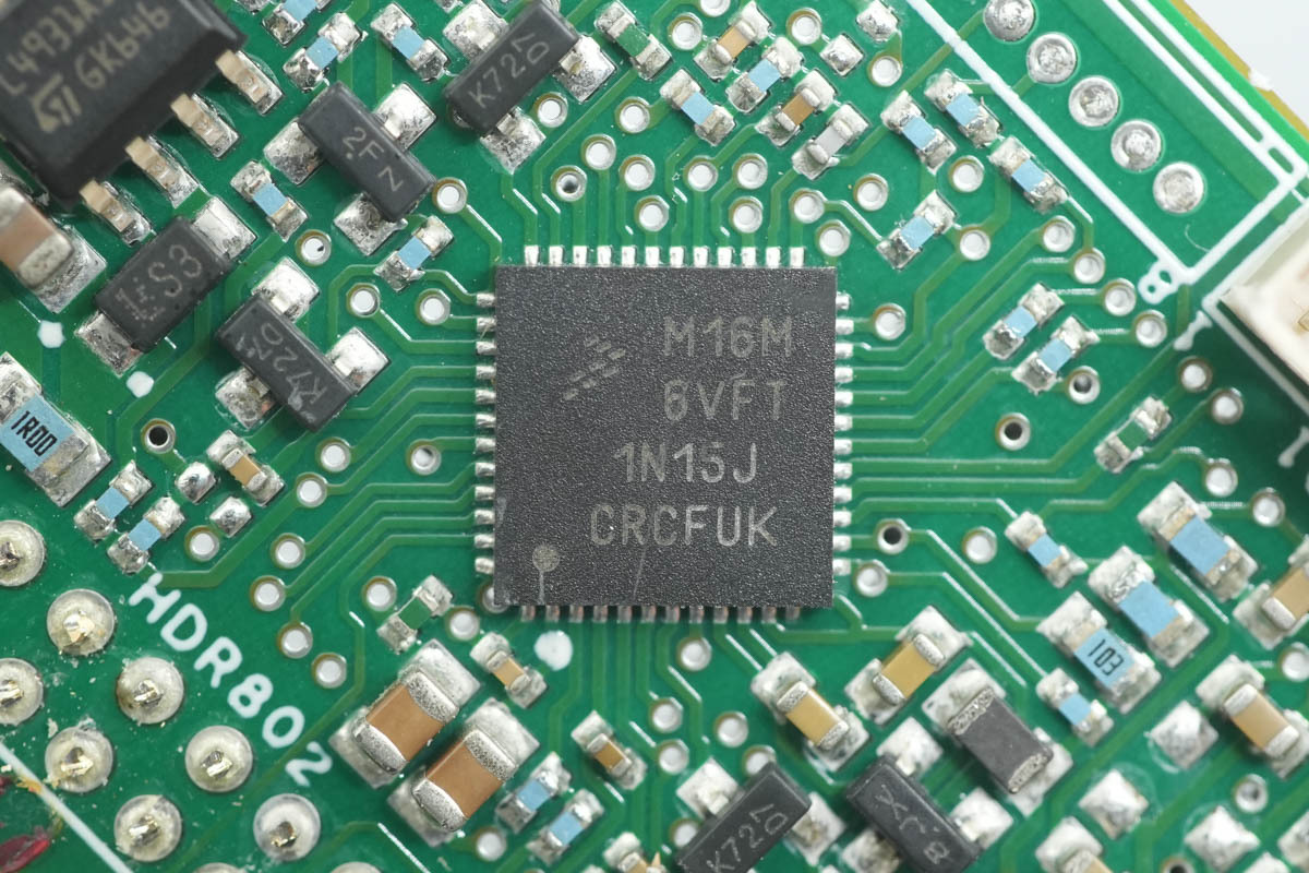
Another MCU is from NXP, model MKL16Z64VFT4, marked M16M6VFT. It features a 48MHz Arm Cortex-M0+ core, 64KB of integrated Flash and 8KB of SRAM, and supports two SPI interfaces, I2S, UART, and I2C. It is housed in a 48-pin QFN package.
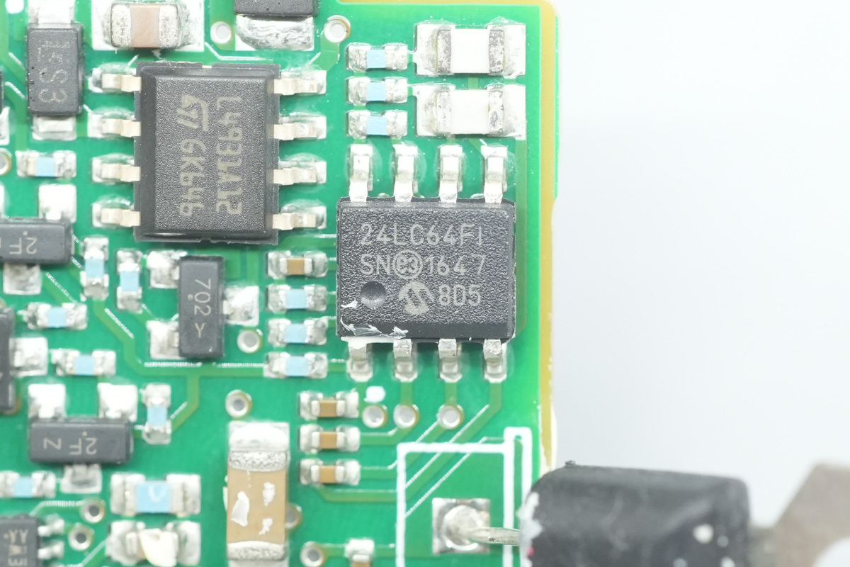
The memory is from Microchip, model 24LC64F, providing 8KB of storage. It operates within a voltage range of 2.5V to 5.5V and housed in an 8-lead SOIC package.
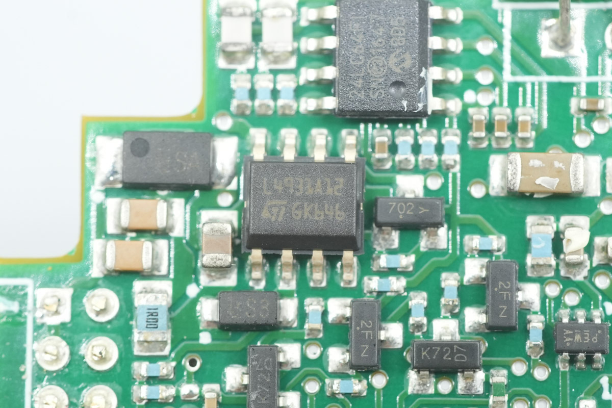
The voltage regulator is from ST, model L4931ABD12. It is an ultra-low-dropout regulator that supports an input voltage of up to 20V, provides a fixed 1.25V output at 250mA, and housed in an SO-8 package.
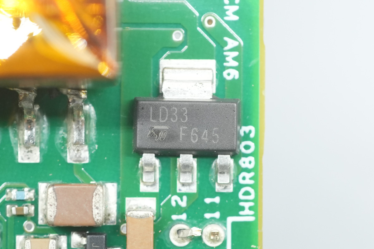
The voltage regulator is from ST, model LD1117S33TR.
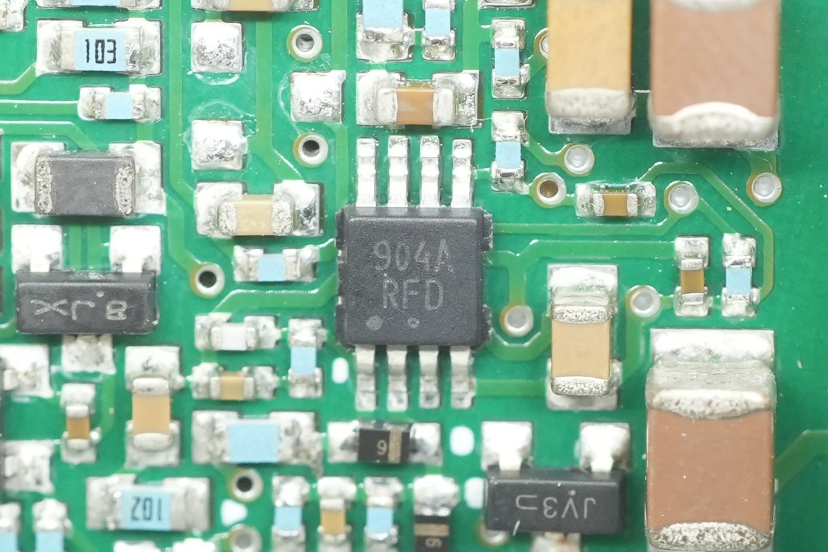
The operational amplifier is from onsemi, model LM2904A.
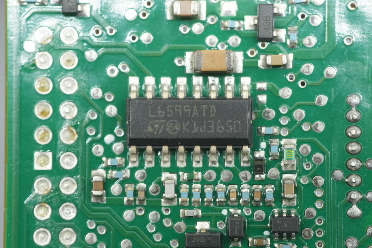
The LLC controller is from ST, model L6599AT, an improved high-voltage resonant controller supporting switching frequencies up to 500 kHz. It features dual-level overcurrent protection, PFC stage control, burst mode for light-load operation, an integrated high-side gate driver, and a built-in bootstrap diode. It is housed in an SO16N package.
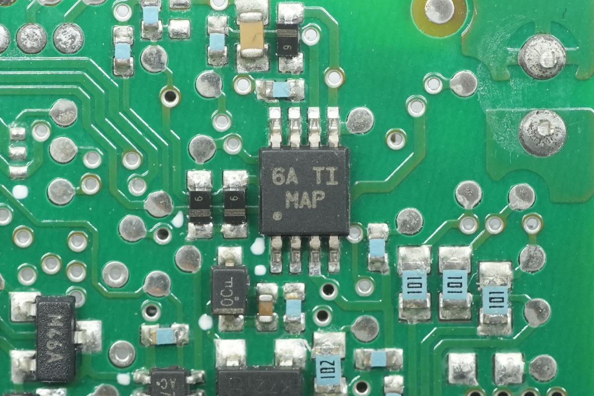
The voltage comparator is from TI, model LM2903.
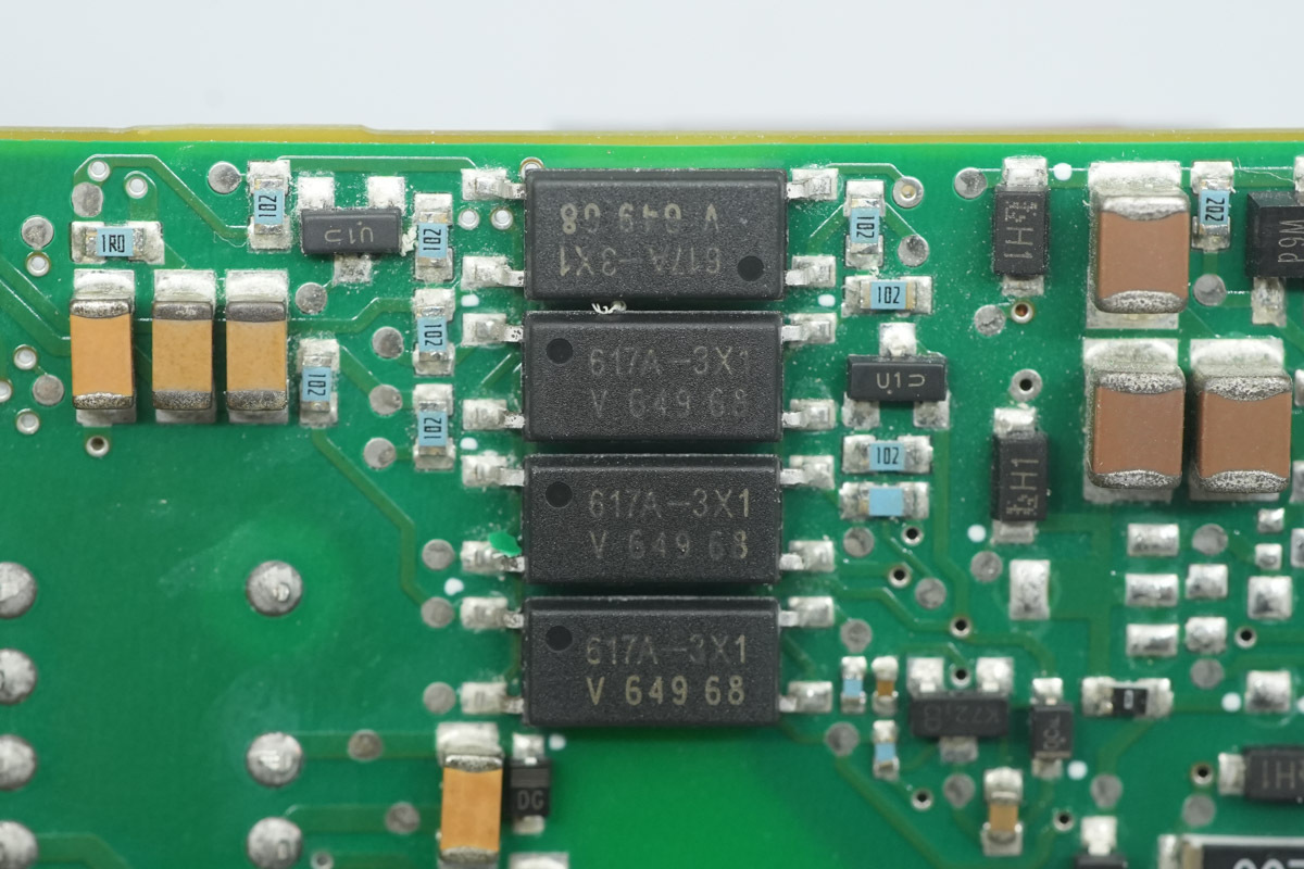
The optocoupler is from Vishay, model VOL617A-3X001T, utilized for isolated communication between MCUs.
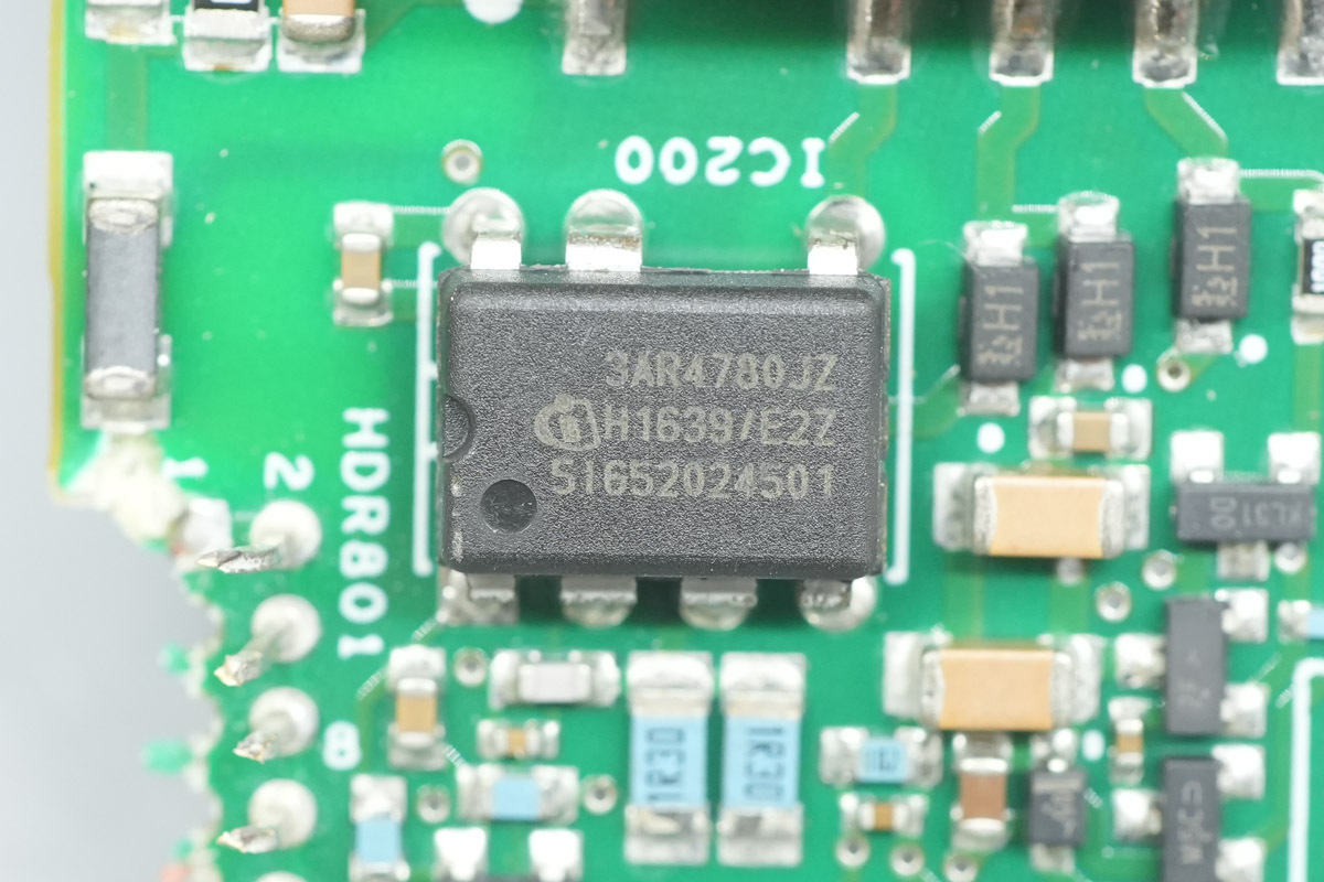
The standby power IC is from Infineon, model ICE3AR4780JZ. It integrates an 800V CoolMOS MOSFET and a high-voltage startup circuit. The device features active burst mode, supports a wide input voltage range for 20W output power, and is housed in a DIP-7 package.
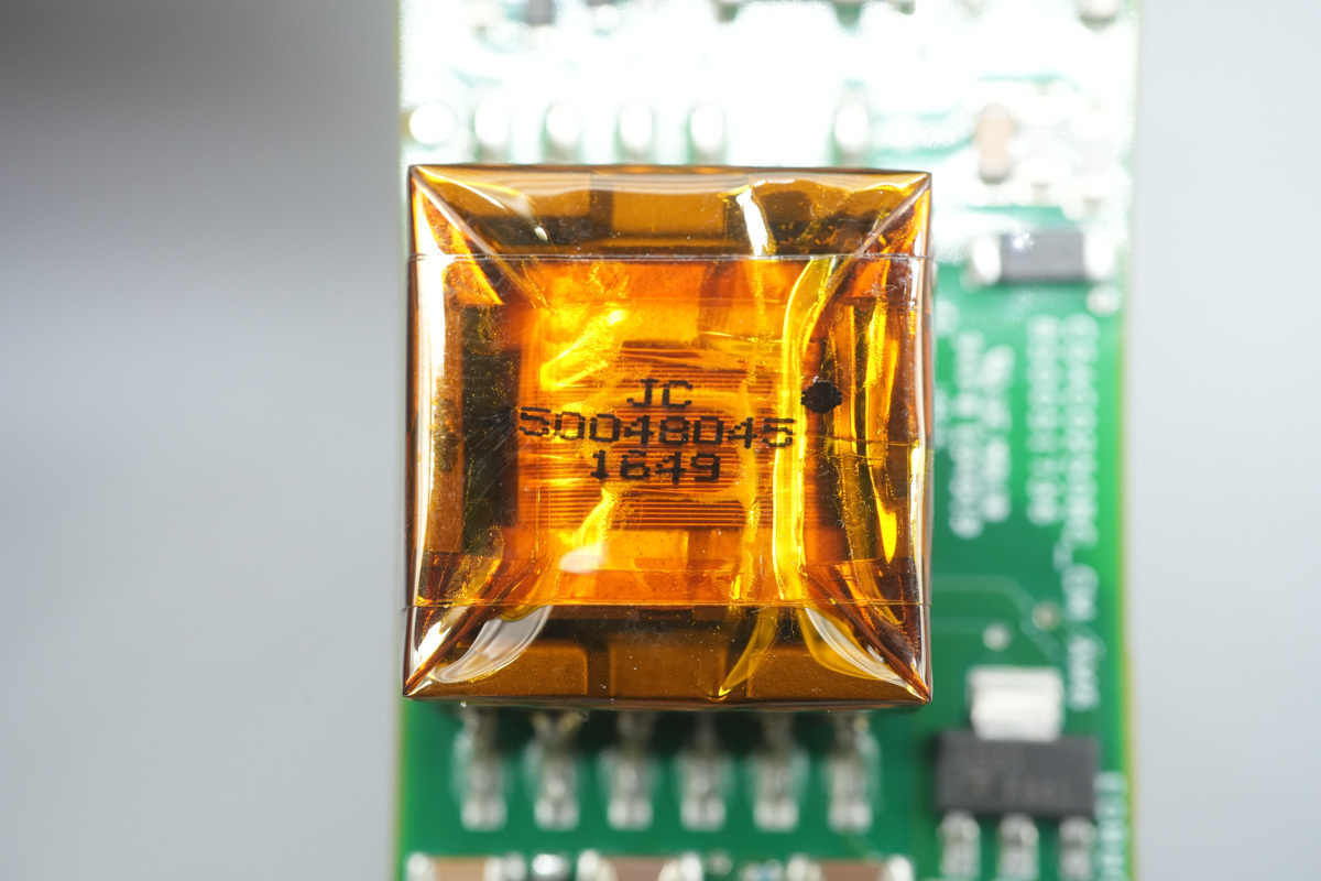
The standby power transformer is insulated with high-temperature adhesive tape.
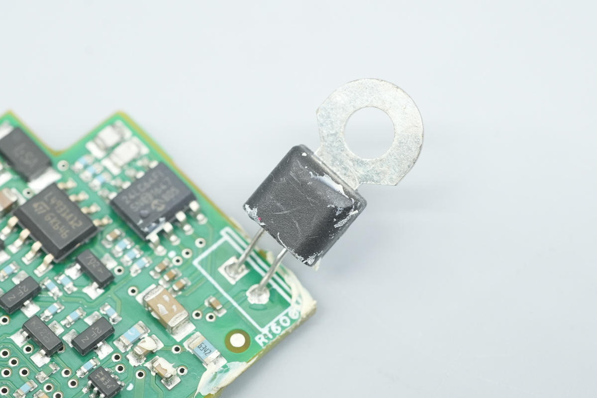
The NTC thermistor is utilized for internal temperature sensing.
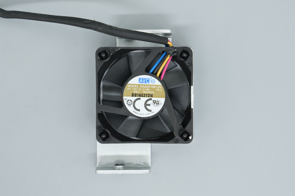
The cooling fan is from AVC, model DA03510B12G, spec 12V and 0.18A.
Well, those are all components of the GE CSAC0250BZ 250W 80 PLUS Platinum Server Power Supply.
Summary of ChargerLAB
The GE CSAC0250BZ server power supply offers 100-240V AC input versatility, delivering a 12V/20.8A main output alongside a 12V/0.1A standby rail. Outfitted with an internal fan, standard AC input, and a dedicated output connector, the unit is built for performance.
A teardown reveals a sophisticated PFC + Half-Bridge LLC + Synchronous Rectification topology. Key components include an onsemi NCP1612A1 PFC controller, Infineon IPP60R330P6 MOSFETs, and ST STTH15L06D rectifiers.
The conversion logic relies on an ST L6599AT LLC controller, Infineon BSC028N06NS synchronous rectifier MOSFETs, and an IR1168S controller. NXP MCU-based digital control ensures precise parameter acquisition. With premium NCC caps and protective conformal coating, this power supply reflects a robust engineering standard.
Related Articles:
1. PowerPi MP305B DC Power Supply Set to Launch on Amazon US — Efficient Power for All Scenarios
2. MOMAX Airbox Go Power Capsule: A Convenient Solution for Charging Anxiety and Cable Management
3. Teardown of the ZIENER 450W GaN TFX PC PSU