Introduction
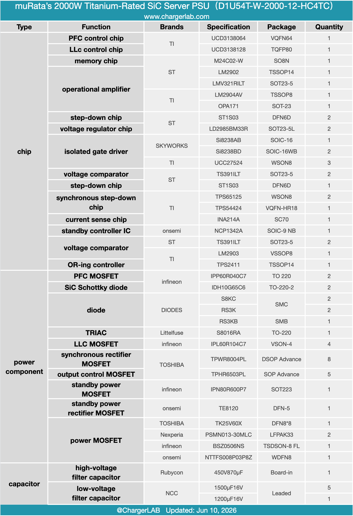
Today we are cracking open muRata’s 2000W Titanium-rated server power supply, model D1U54T-W-2000-12-HC4TC. Designed for versatility, it accepts 100-240V AC and pumps out a steady 12V/166.7A, plus a 3.3V/3A standby rail.
Externally, you’ll find the standard power inlet, status LEDs, and a release mechanism. Inside, it packs a cooling fan, a rear gold-finger connector, and optimized ventilation. The circuit design is a sophisticated SiC based architecture, featuring interleaved PFC, half-bridge LLC, and synchronous rectification. Let’s head inside the chassis to see how Murata delivers such high power density and efficiency.
Product Appearance
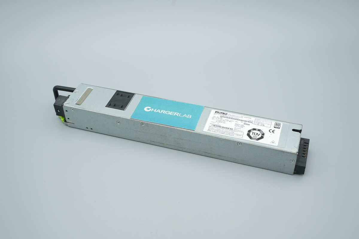
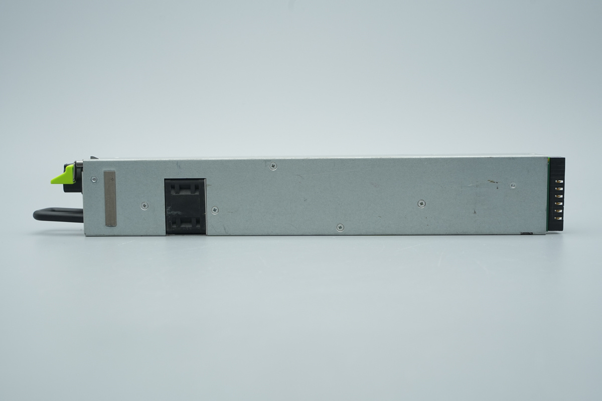
The muRata uses a durable galvanized steel housing for this PSU. The front panel is clearly labeled and features a convenient handle and AC input port, while the rear houses the main connector for plugging into the server backplane.
A conductive fabric is applied to the left side of the unit, and an info label is affixed to the right side.
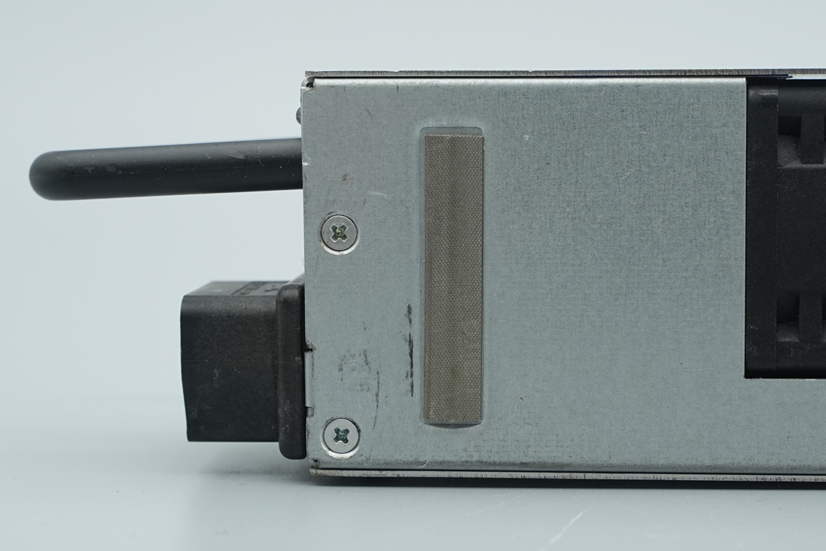
The front panel is fastened with screws and finished with conductive fabric to maintain proper grounding.
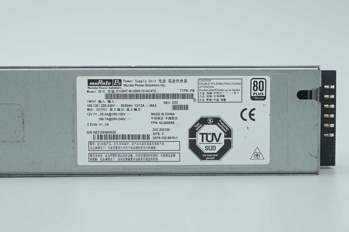
Power Supply Label Specs:
Model: D1U54T-W-2000-12-HC4TC
Input: 100-120/200-240V ~ 50/60Hz, 13/12A MAX
Output: 12V ⎓: 83.3A @ 100-120V ~; 166.7A @ 200-240V ~
Standby Output: 3.3Vsb ⎓, 3A
Efficiency Certification: 80 PLUS Titanium
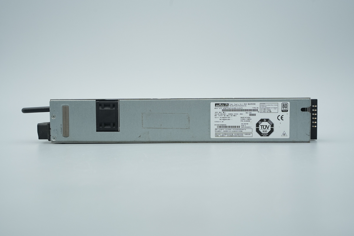
The back of the chassis is equipped with conductive fabric for grounding.
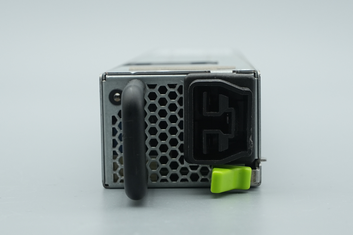
The AC power socket which is integrated extraction handle and locking latch.
The LED indicator for power supply monitoring.
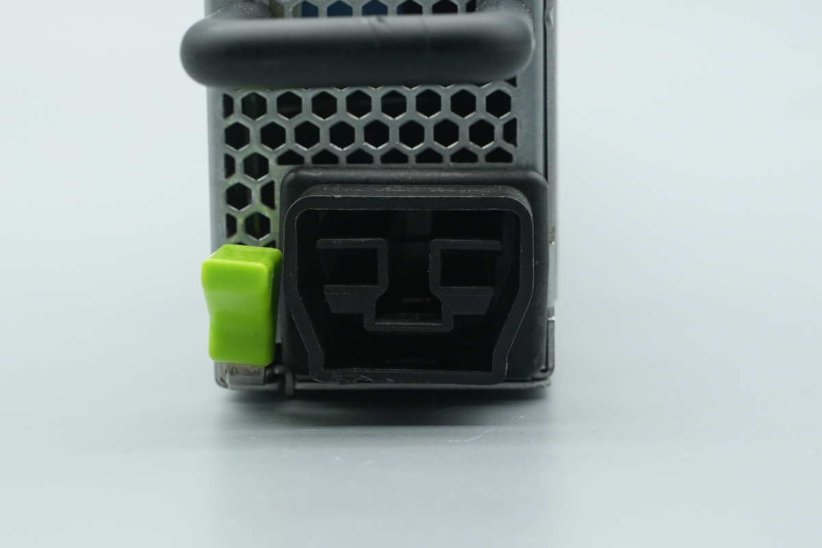
This is the AC power input socket for the unit.
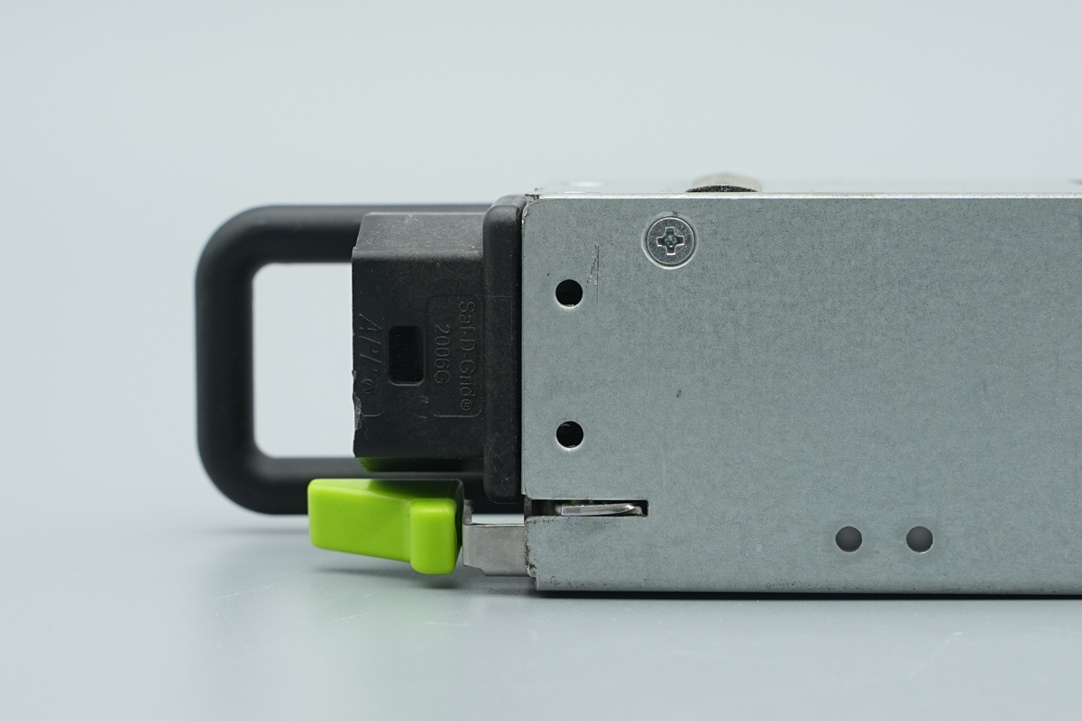
The locking handle is linked to the latch.
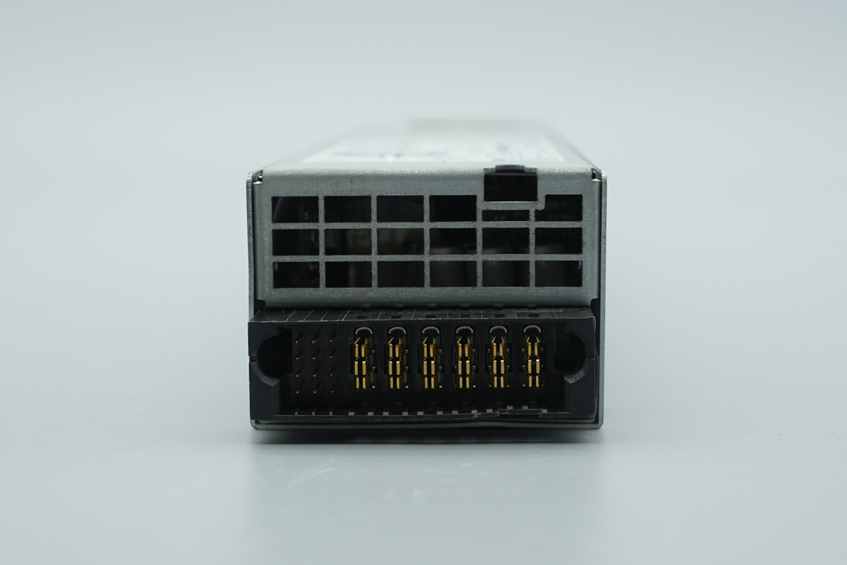
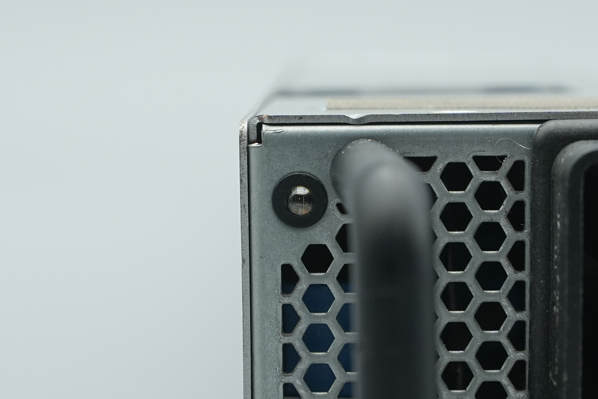
The output end features the ventilation grilles and system connector.
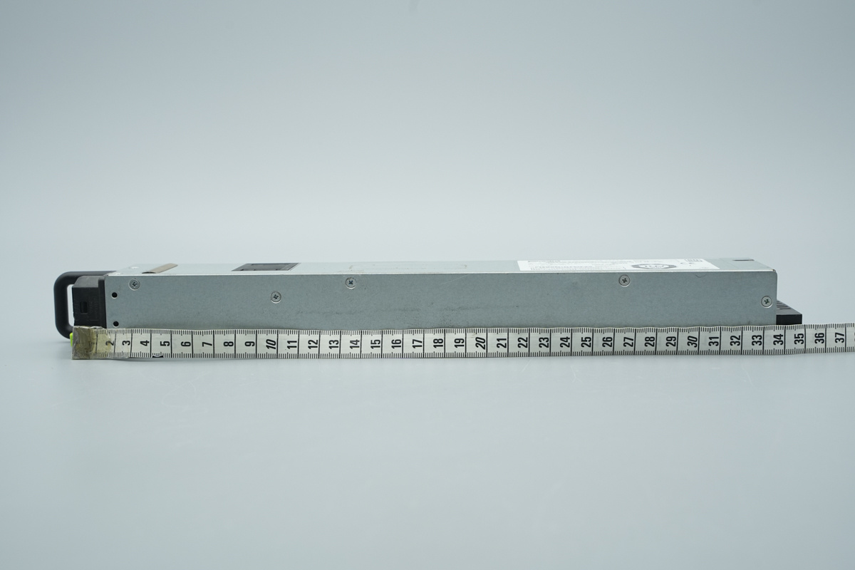
The length of the PSU is about 350mm (13.780 inches).
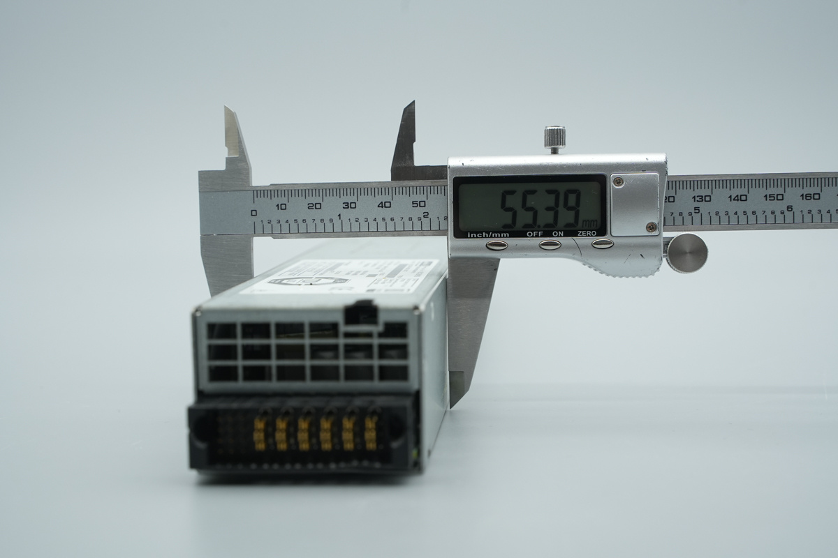
The width of the PSU is about 55.4mm (2.182 inches).
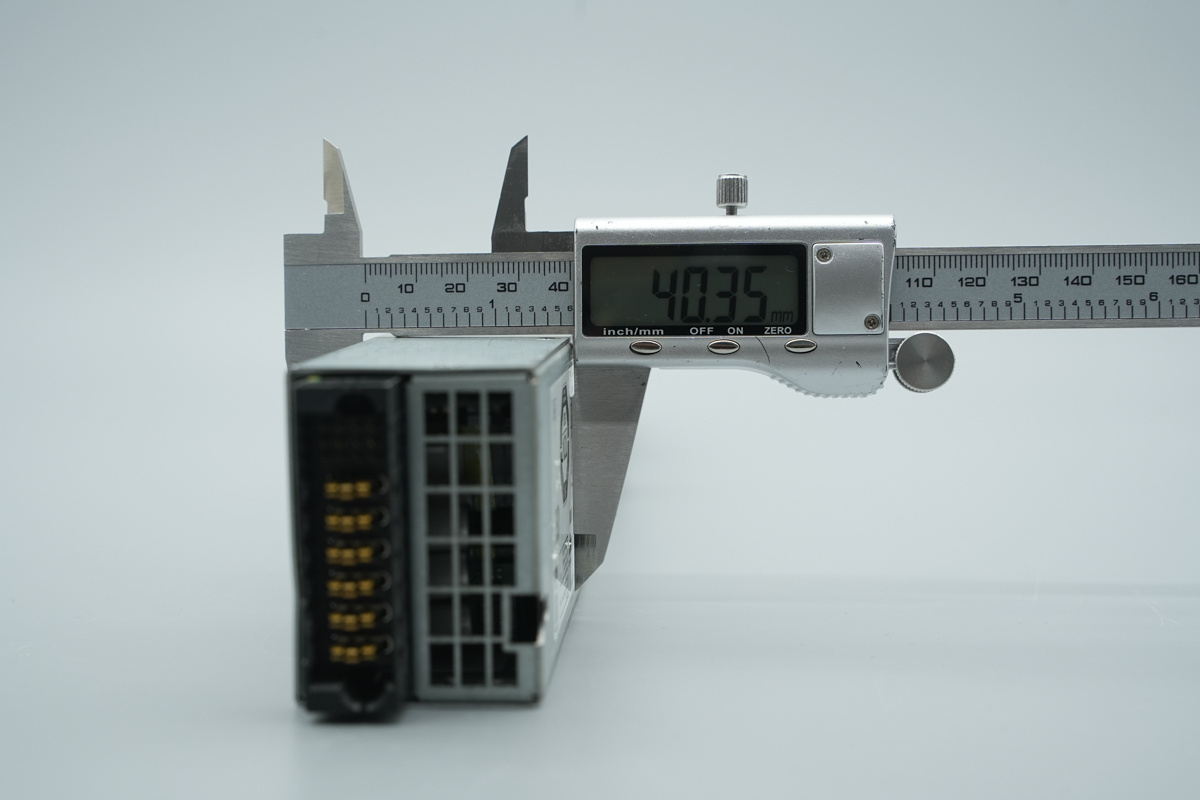
The thickness of the PSU is about 40.4mm (1.591 inches).
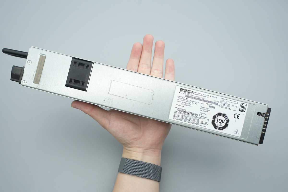
That's how big it is in the hand.
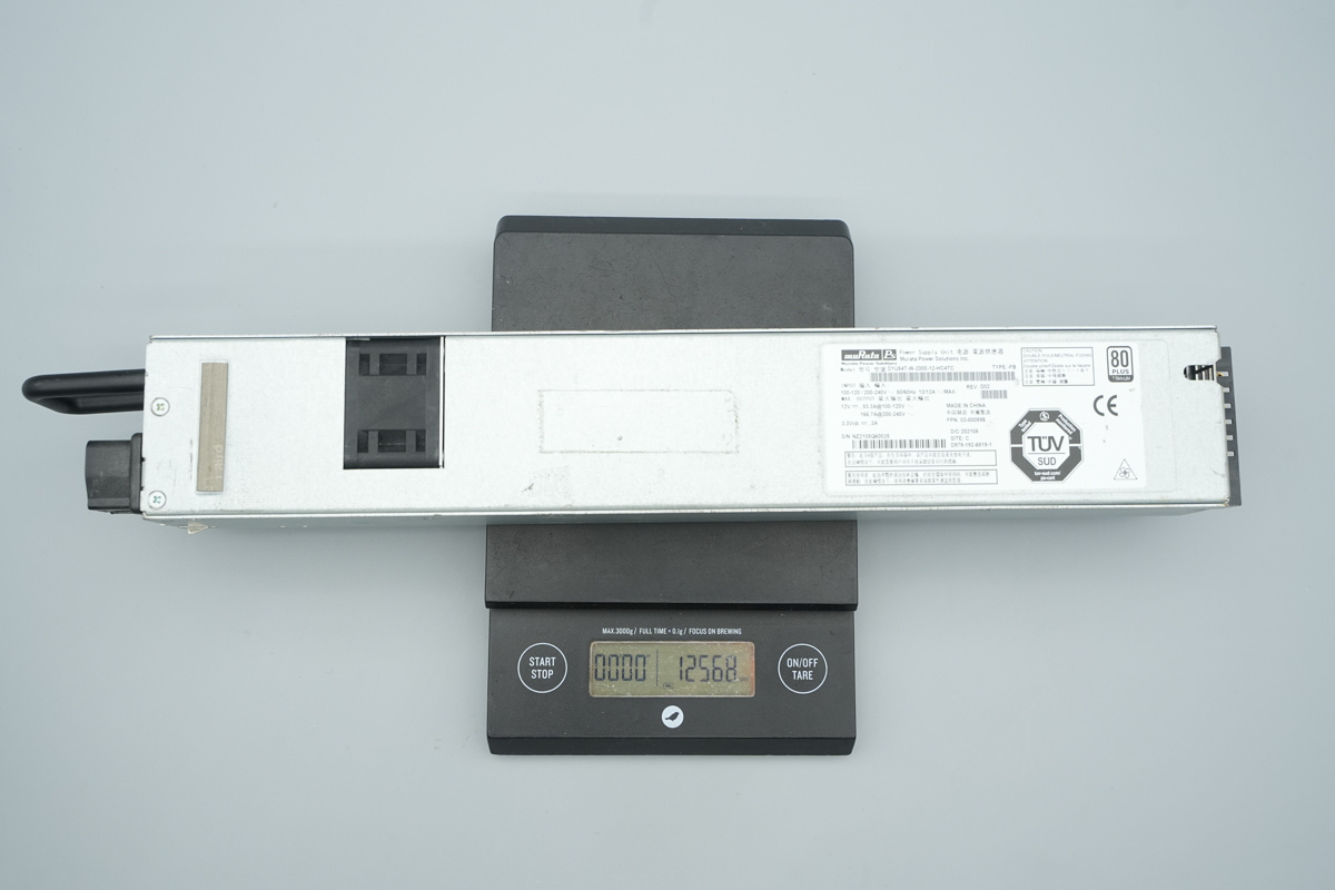
The weight is about 1257g (44.34 oz).
Teardown
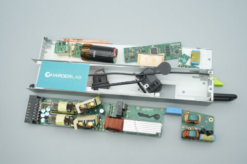
We have finished the exterior overview, let’s crack open the chassis and dive into the internal design and components.
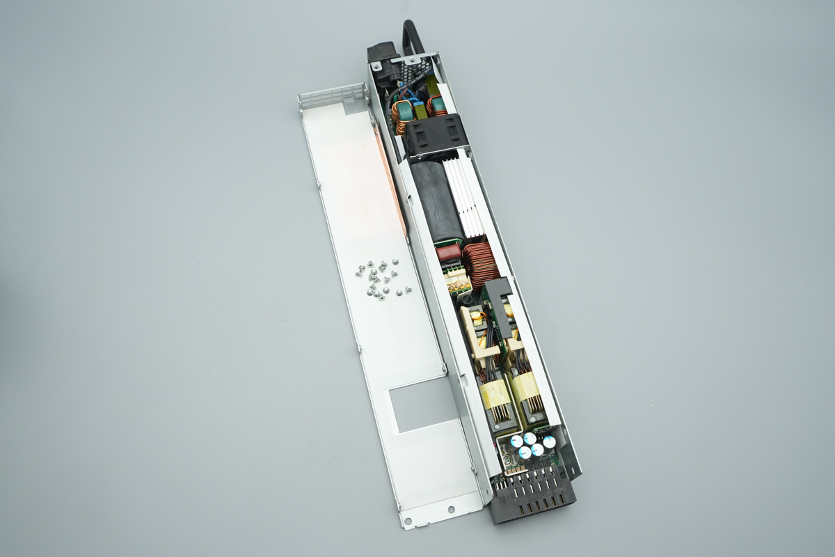
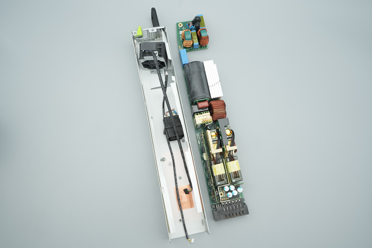
Removing the casing screws and detaching the outer metal shell to access the internal components.
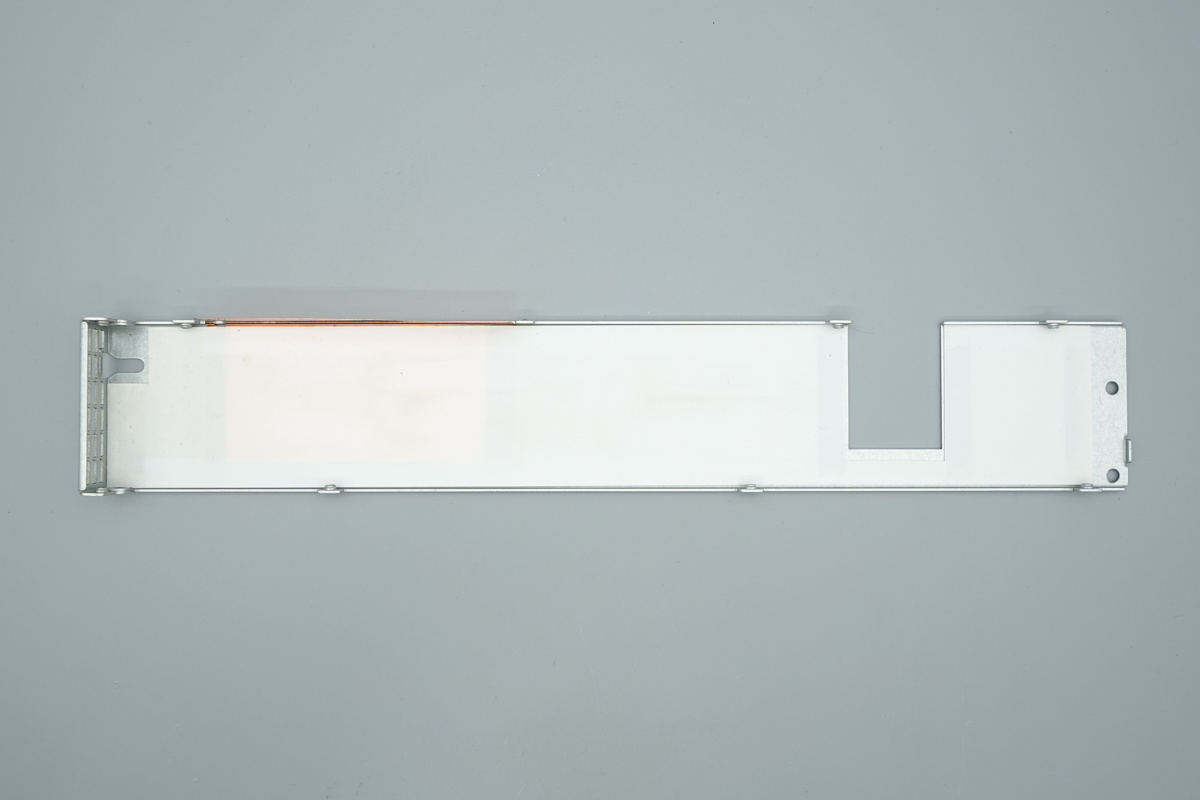
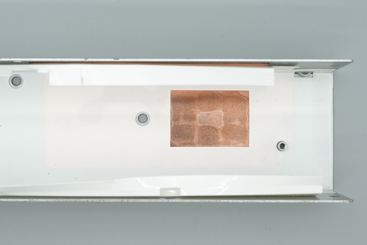
The casing contains insulating Mylar sheets and copper shielding foils.
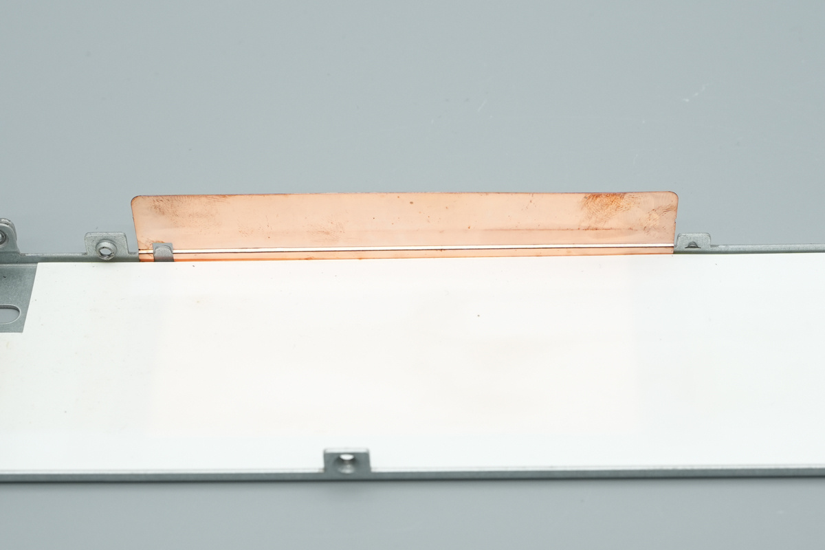
Here is the copper shielding foil located directly above the transformer.
The PCBA is fixed to the housing with screws, which vias a white Mylar sheet provides electrical isolation between the PCB and the metal chassis.
The power socket is directly soldered to the PCBA using heavy-duty wires.
The PCBA module is insulated from the casing by a Mylar sheet.
This is the mounting screw used to secure the PCBA.
Remove the mounting screw to extract the PCBA.
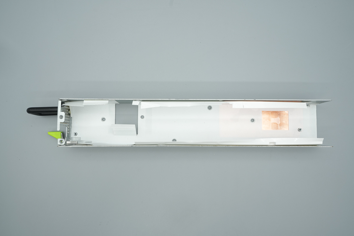
The inside of the casing features Mylar insulation, and copper foil is attached to shield the transformer.
The Mylar sheet features cutouts, using thermal pads to dissipate heat from the synchronous rectifier MOSFETs.
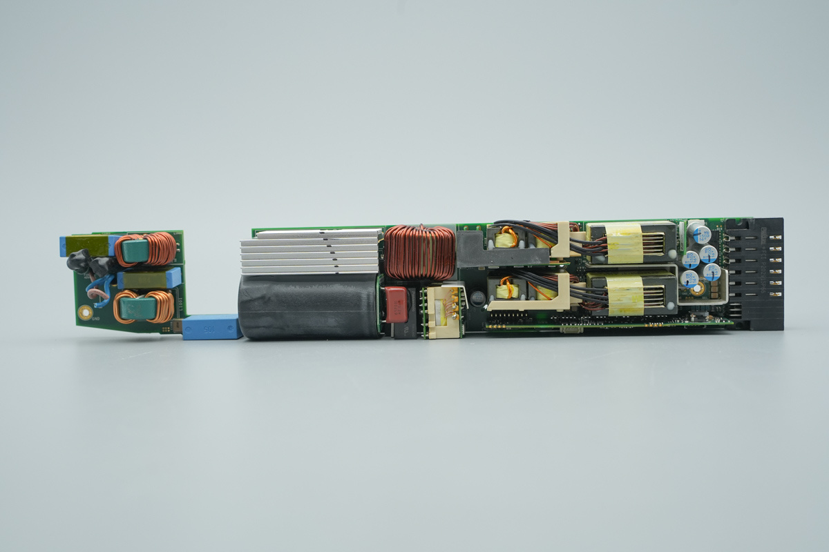
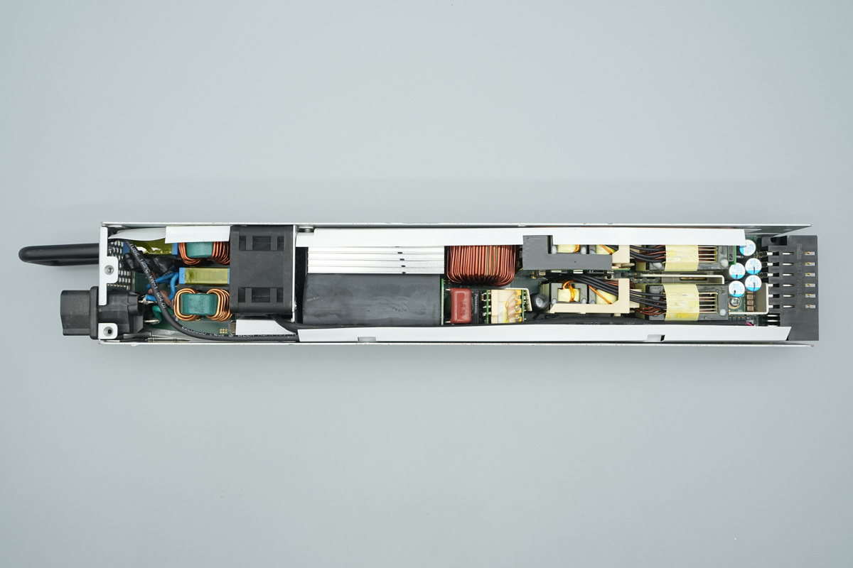
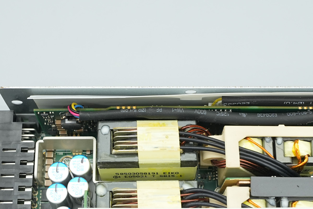
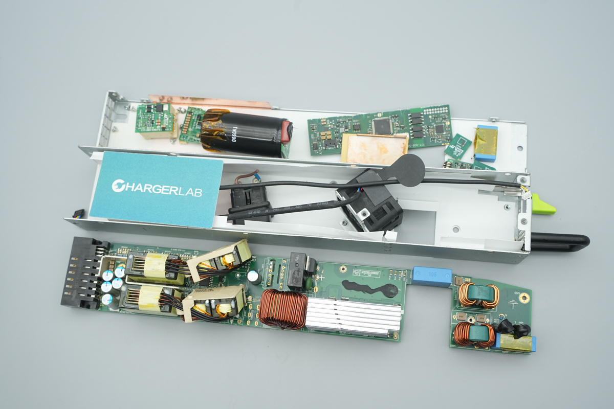
The input end of the PCBA features a fuse, common-mode chokes, and safety X2 caps. Centrally, a heatsink is employed to dissipate heat from the PFC MOSFETs and rectifier MOSFETs, with high-voltage filter caps positioned beneath it. To the right of the heatsink lies the PFC boost choke, with the standby power transformer located below it.
On the right side, the assembly incorporates a PCB for the LLC MOSFETs, a resonance cap PCB, the resonant chokes, and the main LLC transformer. The output end comprises solid filtering caps, a heatsink, and the output connector. A secondary control PCB is mounted longitudinally beneath the transformer.
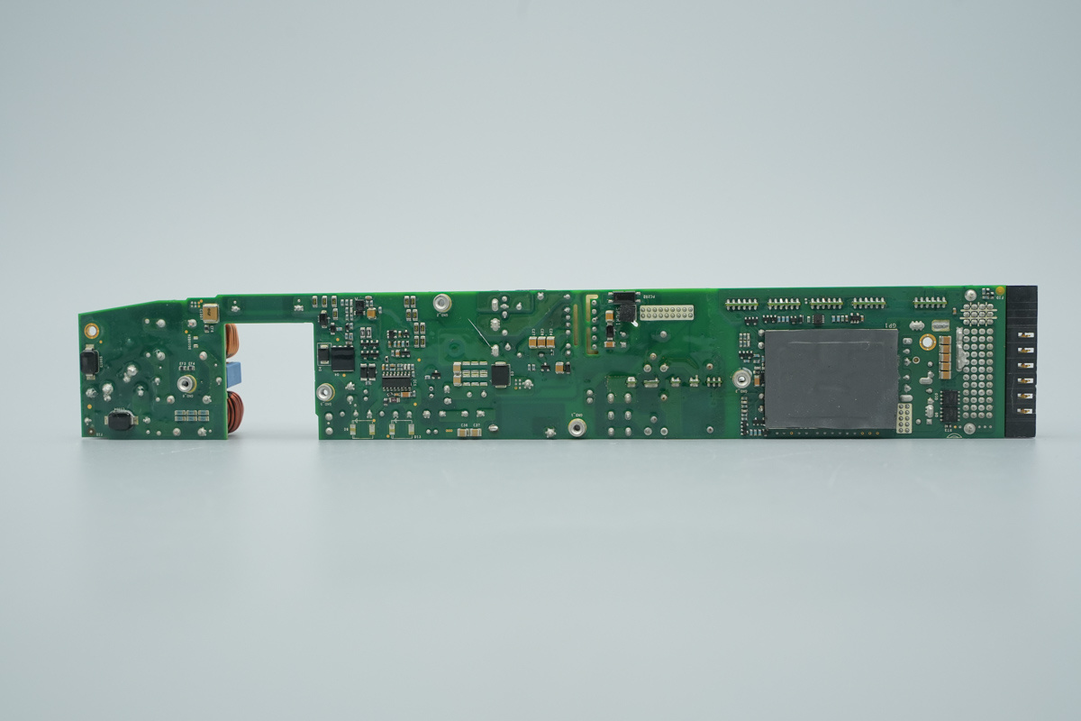
The back of the PCBA features SMD Y-caps, isolated gate drivers, and diodes. Synchronous rectifier MOSFETs are positioned beneath the thermal pad on the right, accompanied by output control MOSFETs located on the right.
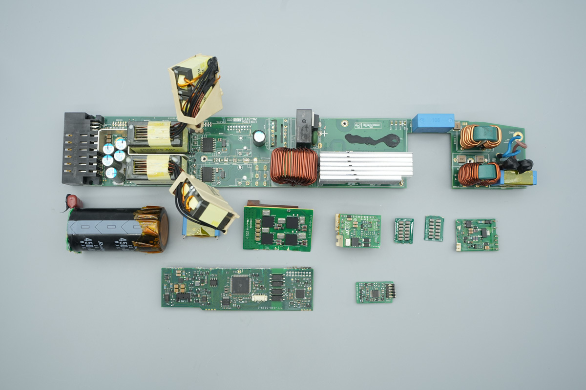
Desoldering and removing PCBs and high-voltage filter caps to continue the disassembly.
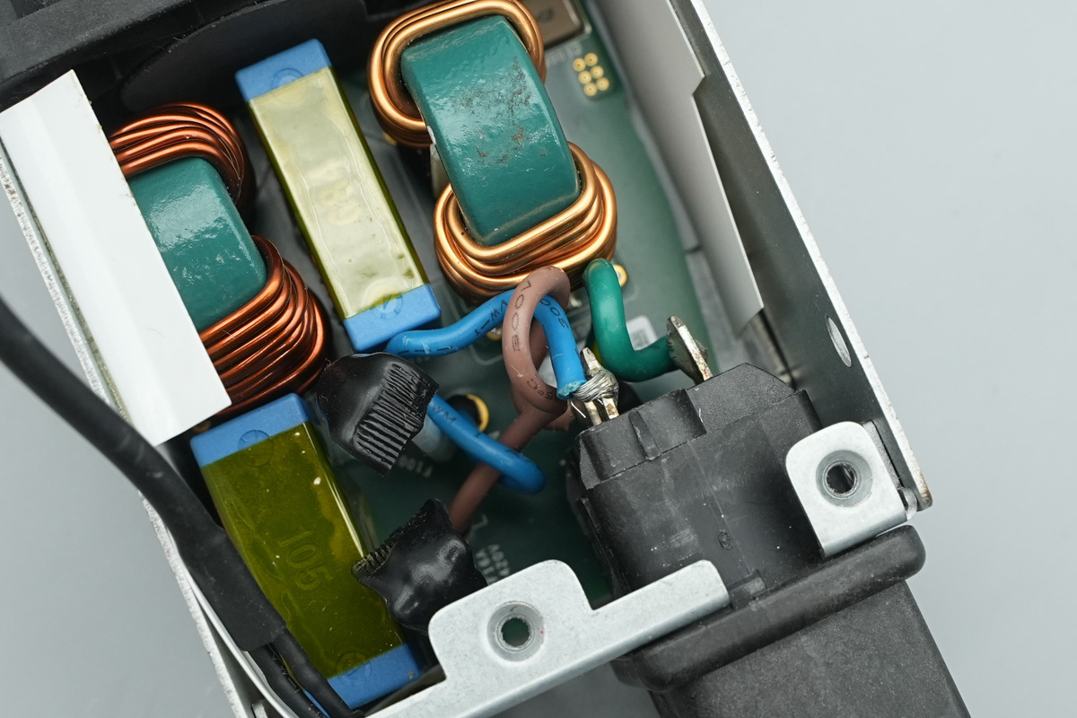
The input fuse with heat-shrink insulation.
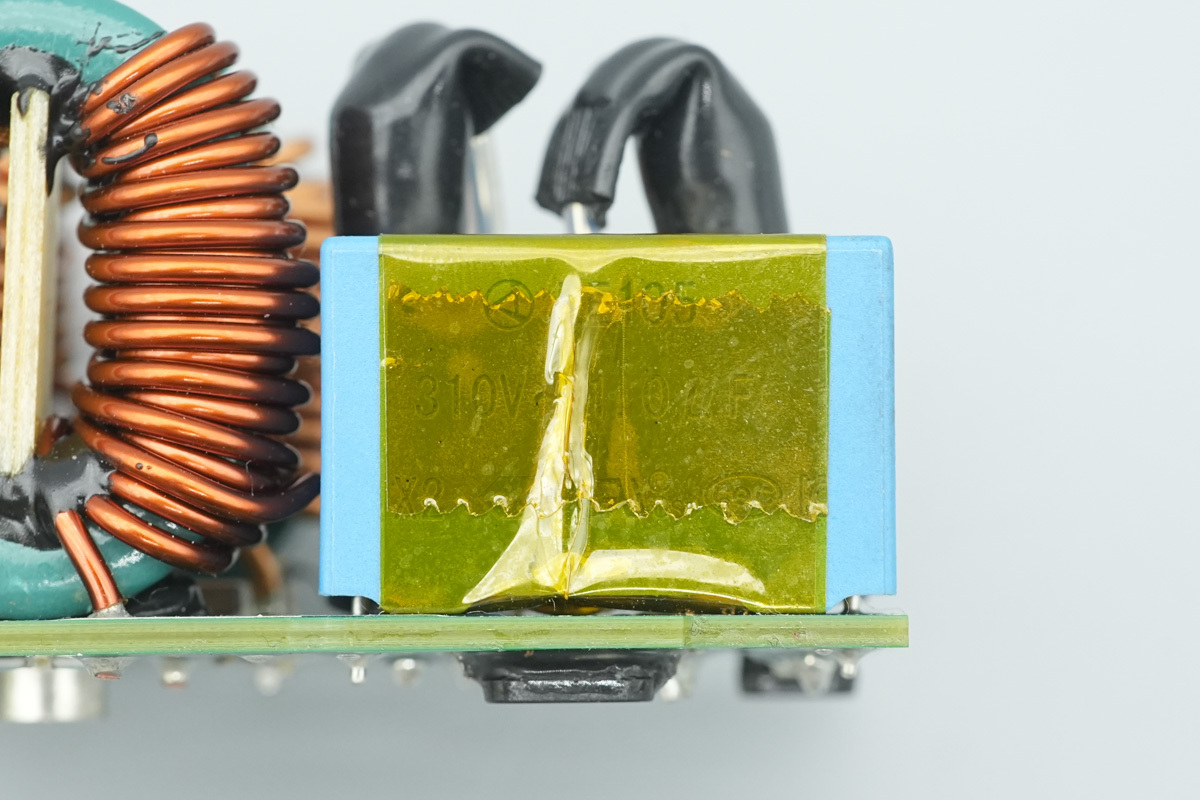
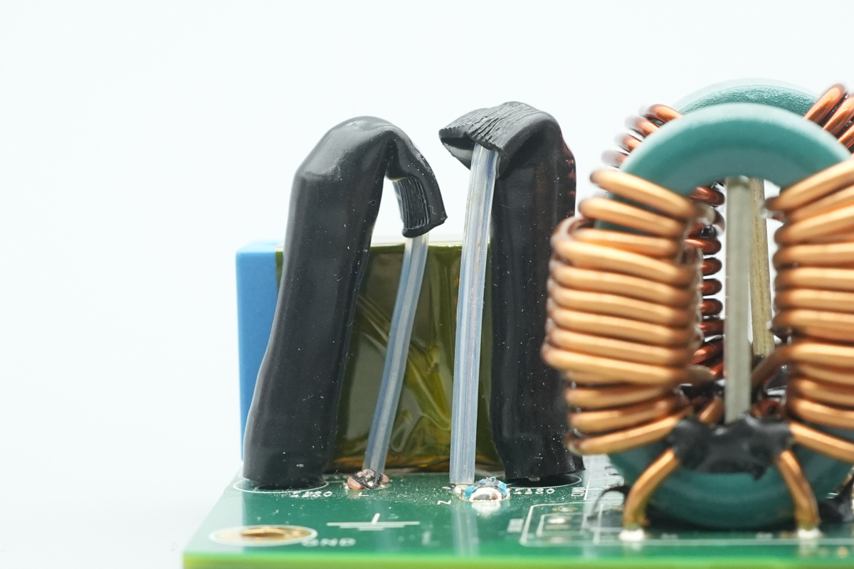
The safety X2 cap is from OKAYA, model LE105, spec 1μF.
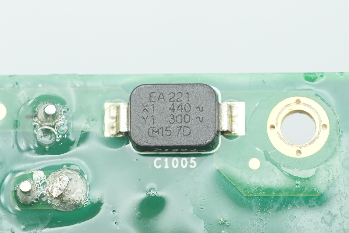
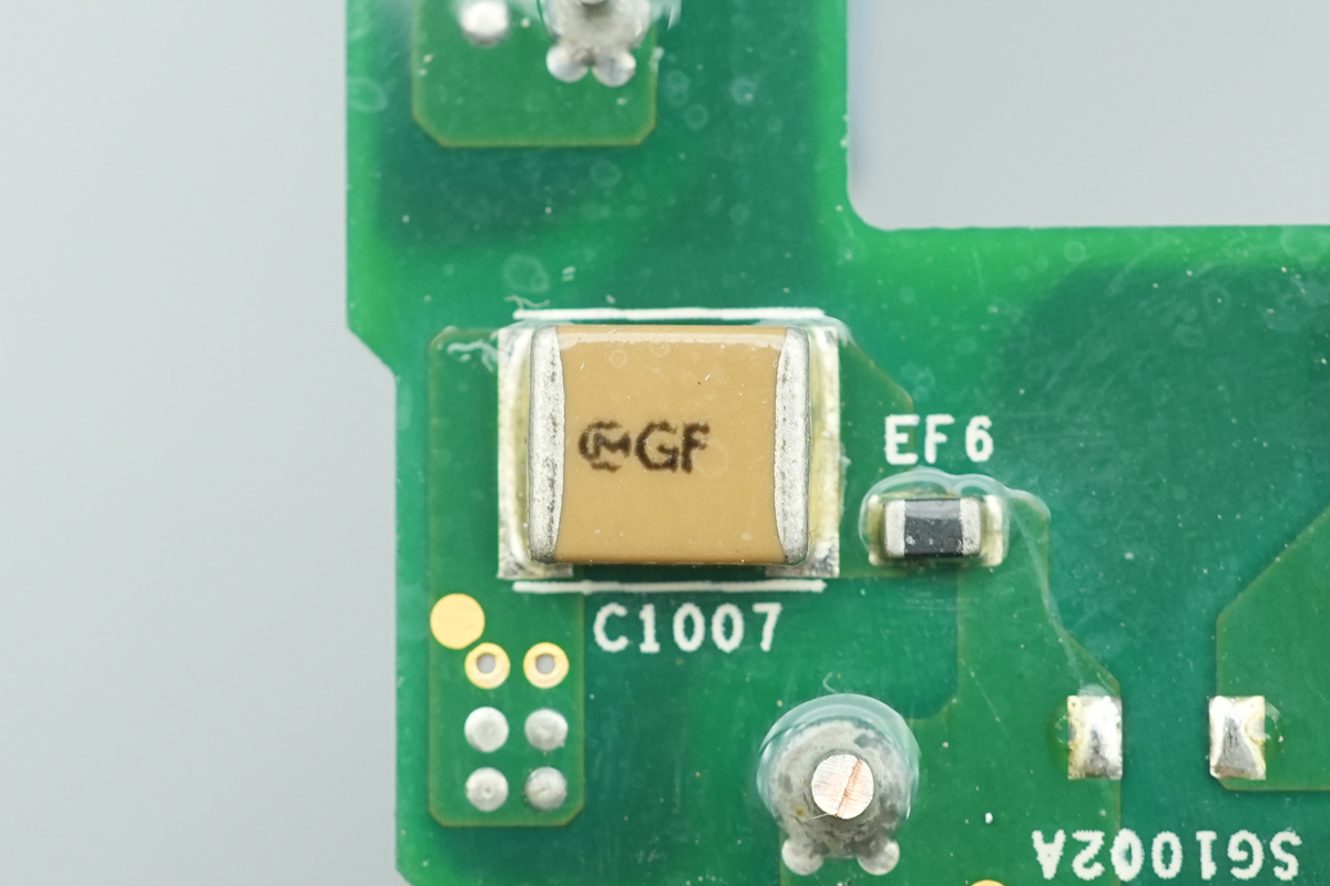
The SMD Y-cap is from muRata, model EA221.
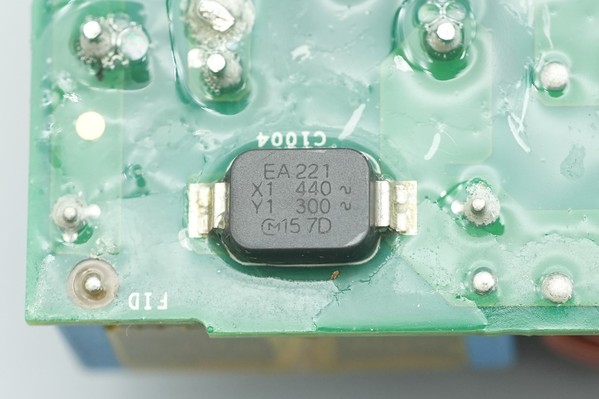
Another one shares the same model.
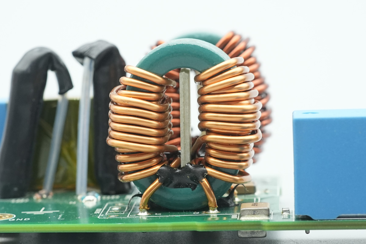
The common-mode chokes are wound with enameled wire.
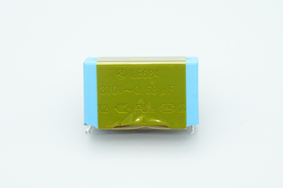
The safety X2 cap, model LE684, spec 0.68μF.
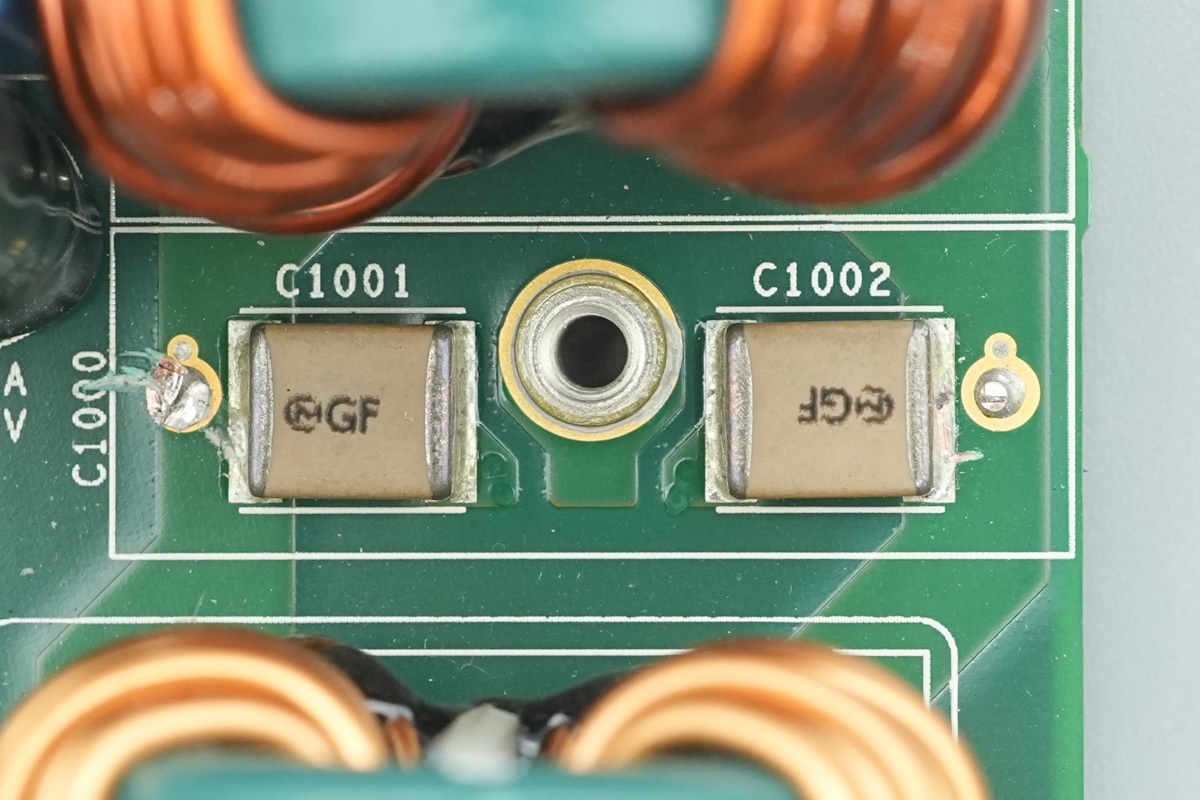
The SMD Y-caps are from muRata.
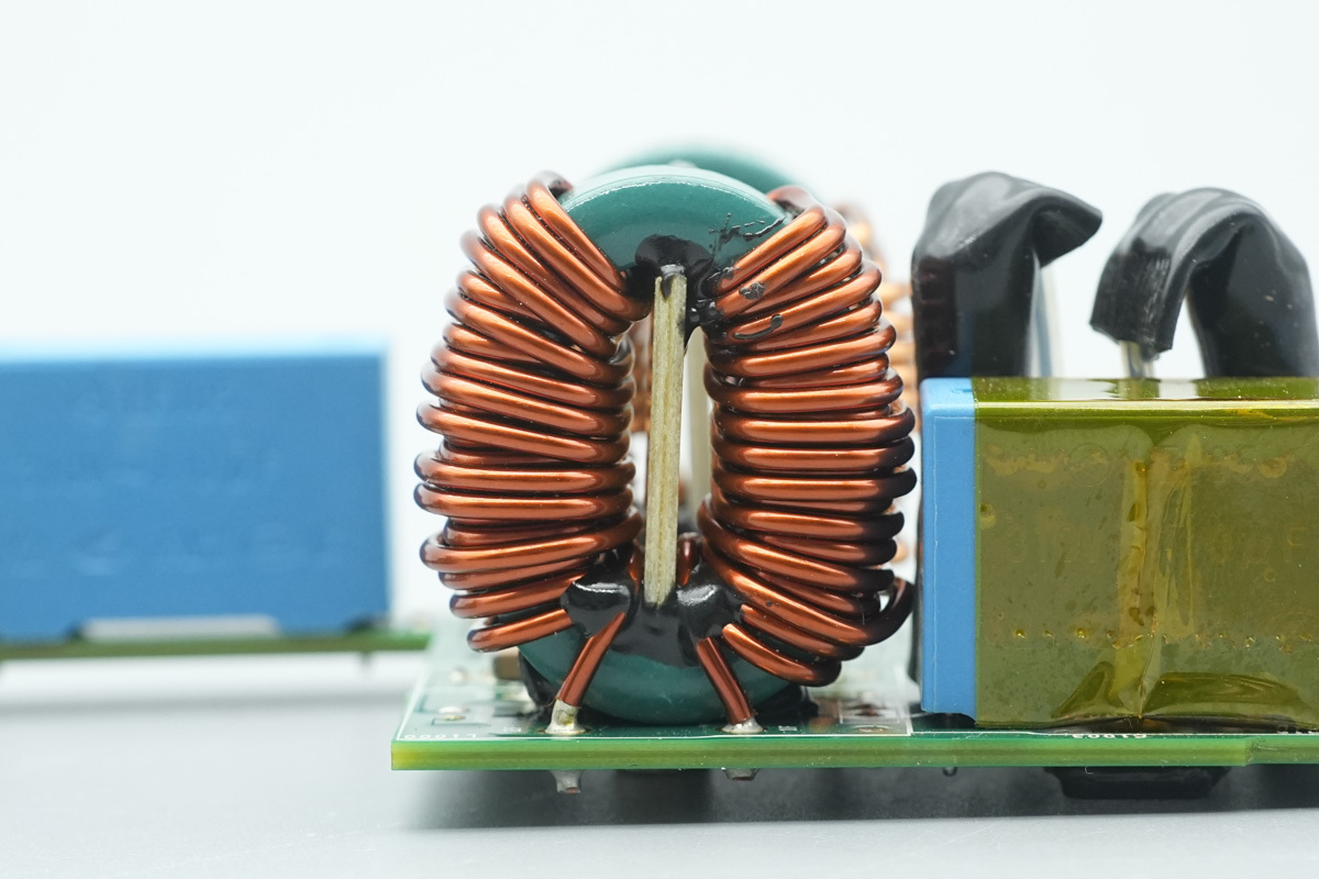
The common-mode choke on the other side is also wound with enameled wire.
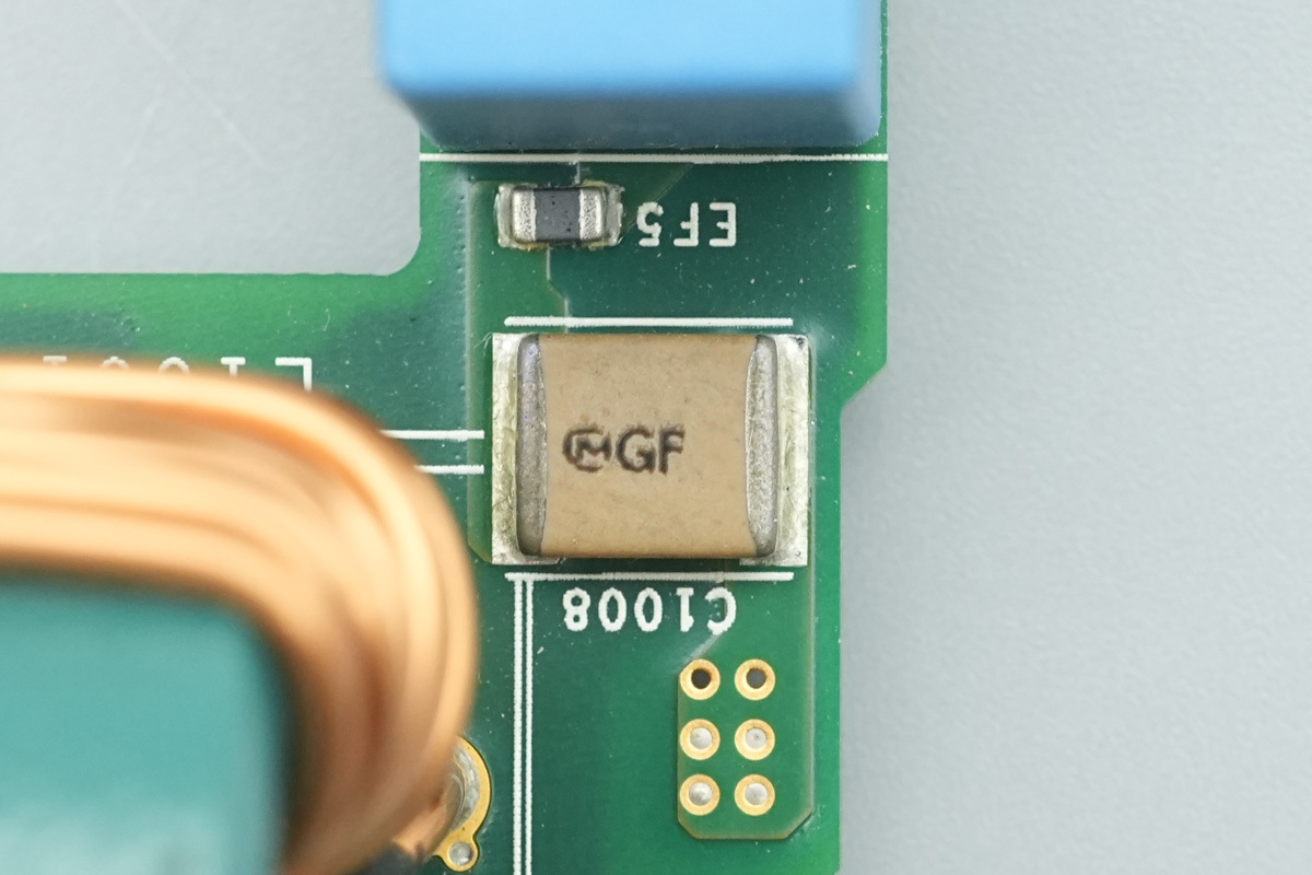
The SMD Y-cap is from muRata.
The other side also features a SMD Y-cap.
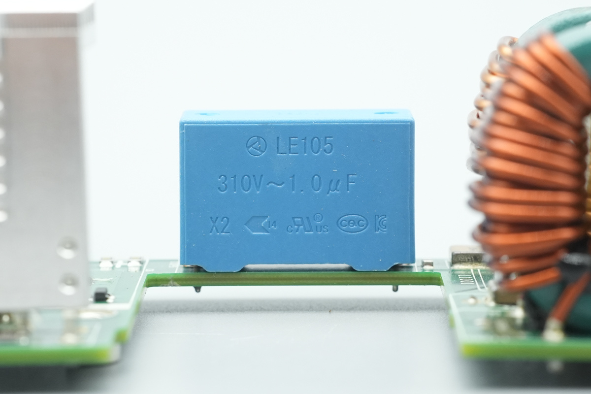
The safety X2 cap, spec 1μF.
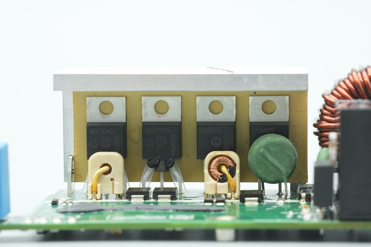
The bidirectional PFC MOSFETs and rectifier MOSFETs are secured to the heatsink.
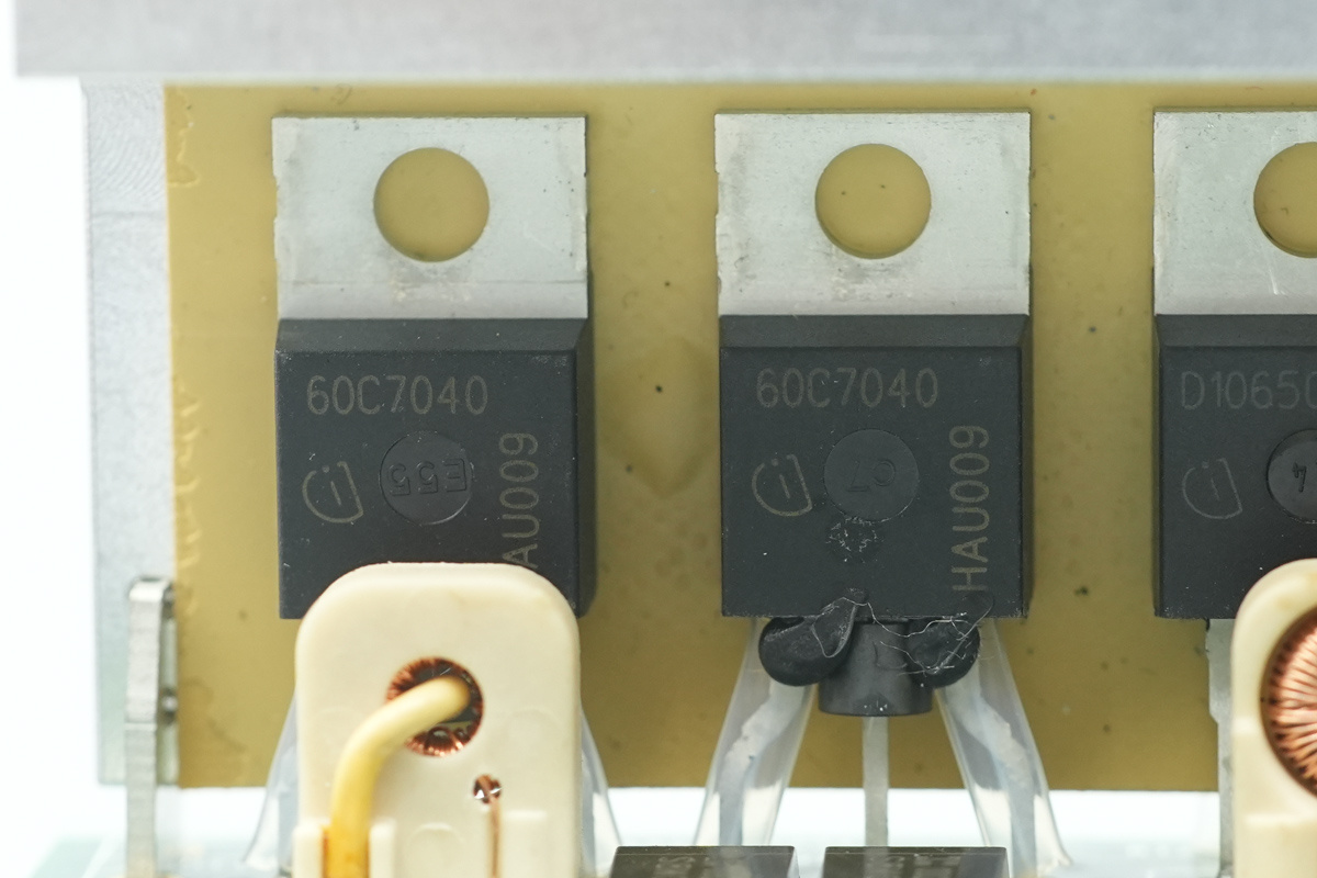
The two PFC MOSFETs on the left are from Infineon, marked 60C7040, model: IPP60R040C7, belonged to the CoolMOS C7 series, NMOS, 650V and 40mΩ, housed in a TO-220 package.
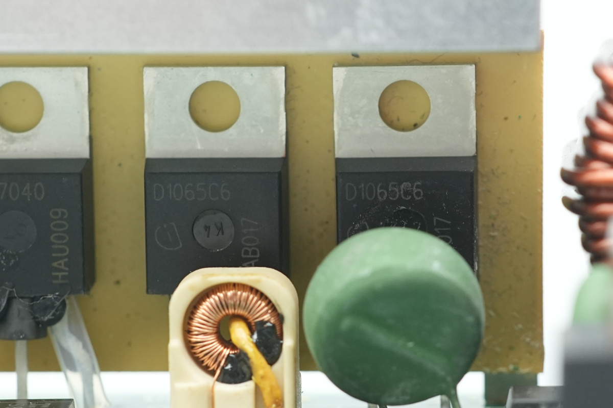
The SiC Schottky diodes are sourced from Infineon, marked D1065C6, model IDH10G65C6, which are the 6th-generation SiC Schottky diodes, rated at 650V/10A, housed in a TO-220-2 package.
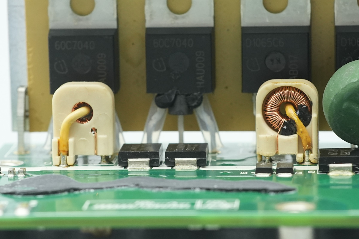
Two current transformers are implemented to monitor the MOSFET currents.
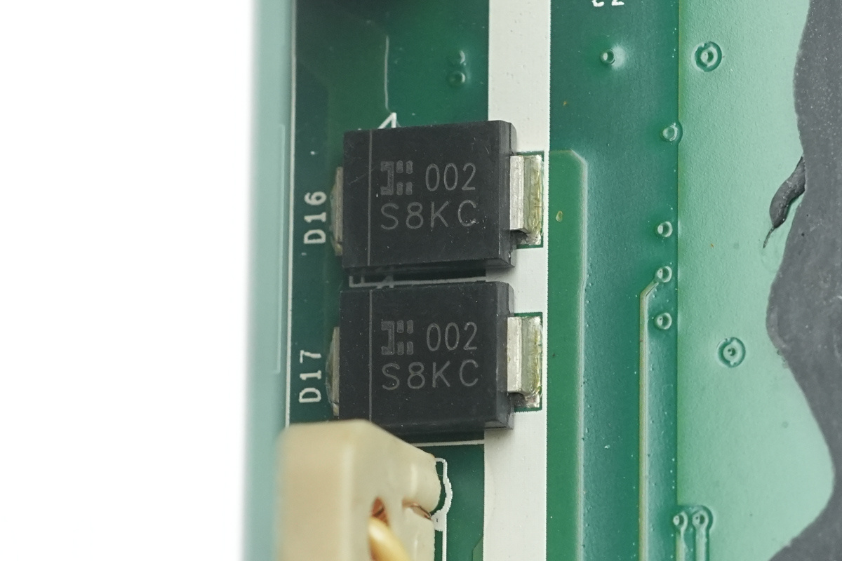
The diodes are sourced from Diodes Inc., model S8KC, rated at 800V/8A, housed in an SMC package.
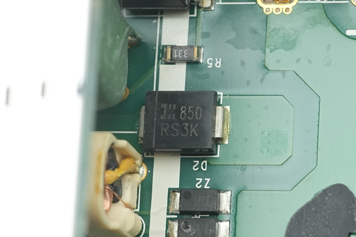
The diode is from Diodes Inc., model RS3K. It is a fast-recovery rectifier diode rated at 800V/3A, housed in an SMC package.
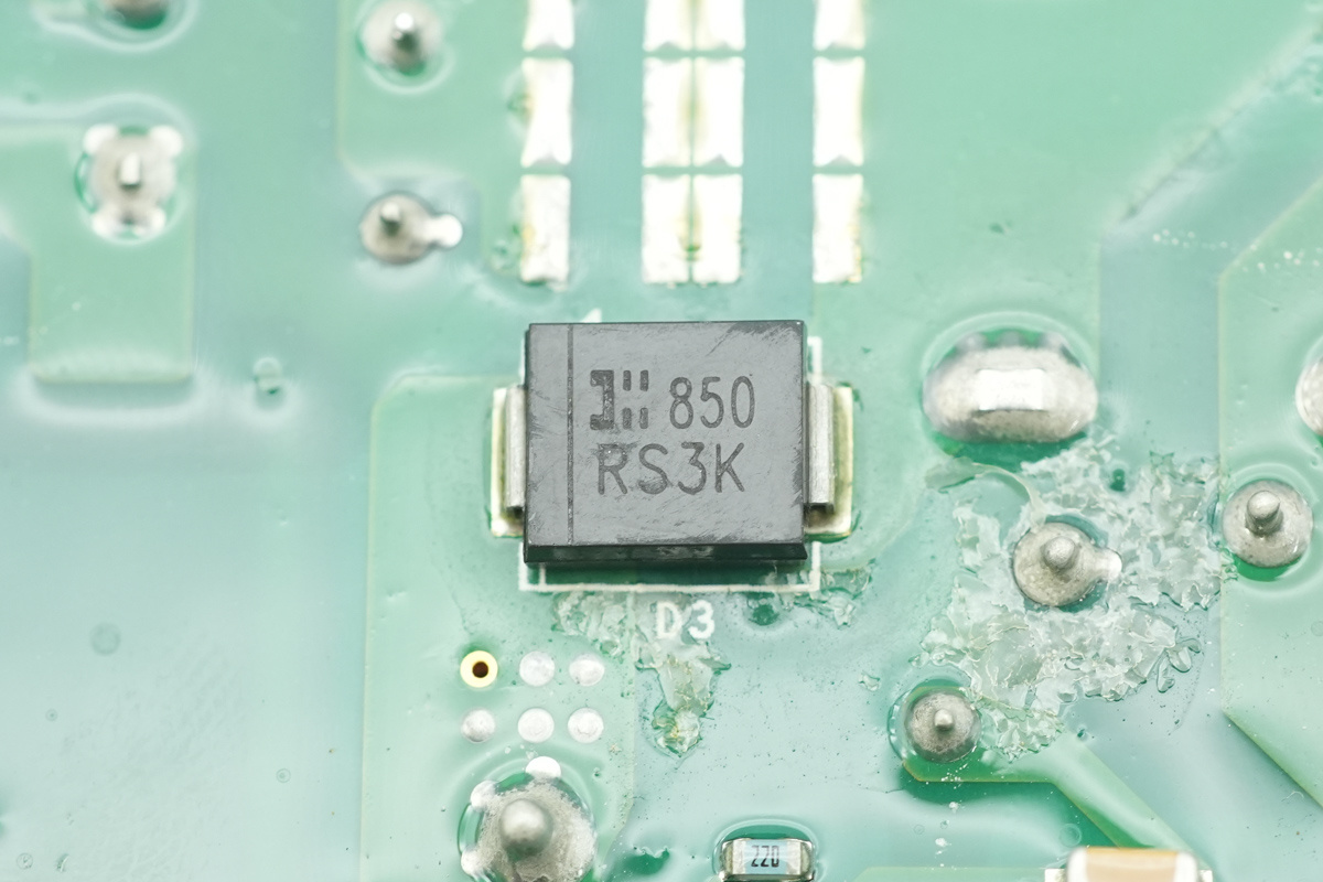
Another one shares the same model.
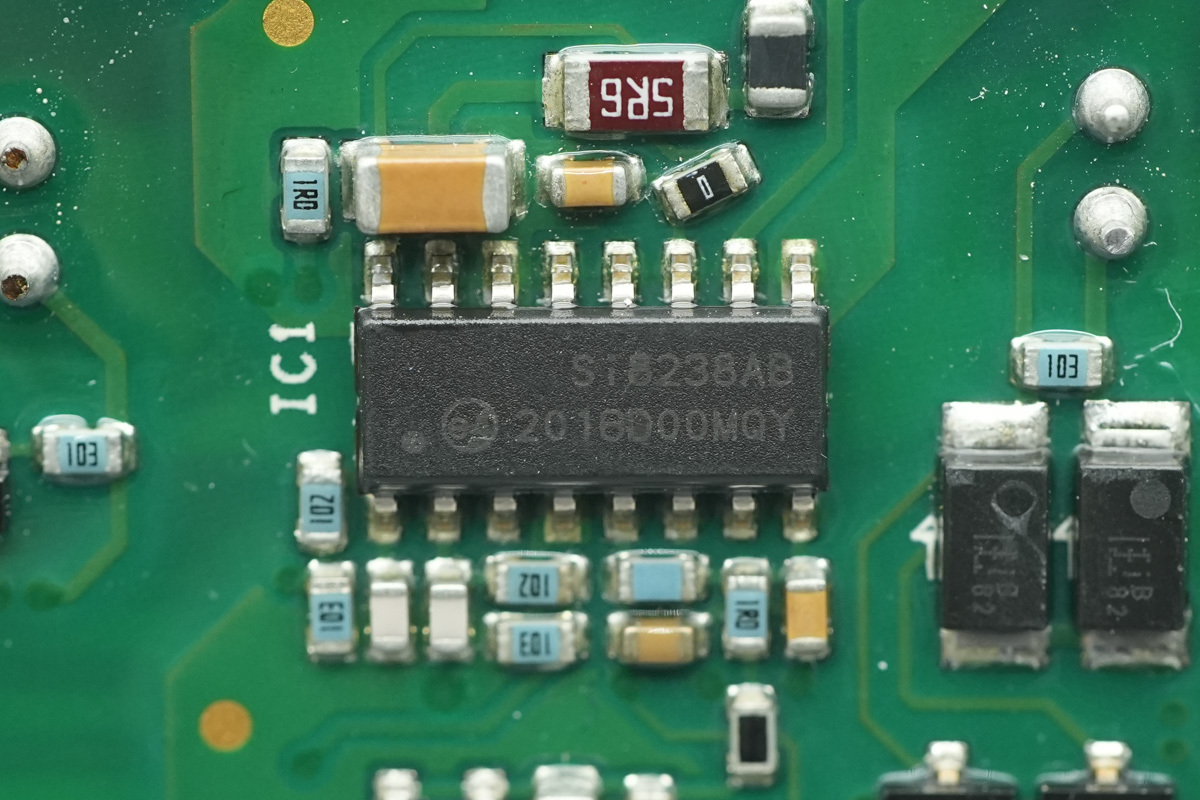
The isolated gate driver is from Skyworks, model Si8238AB, it's a dual-channel isolated gate driver offering a 4A peak current and 5kVrms isolation, housed in a SOIC-16 package.
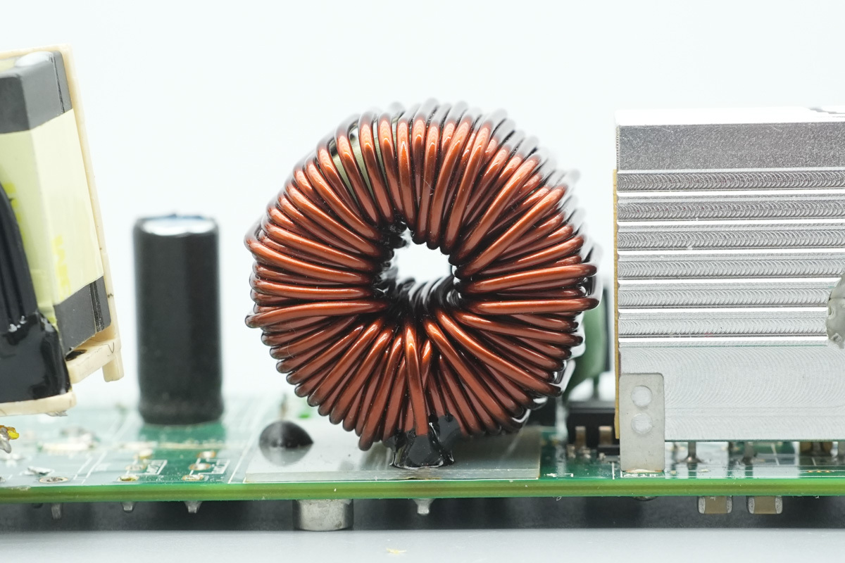
The PFC choke is wound with enameled wire, with a Bakelite insulating board positioned at its base.
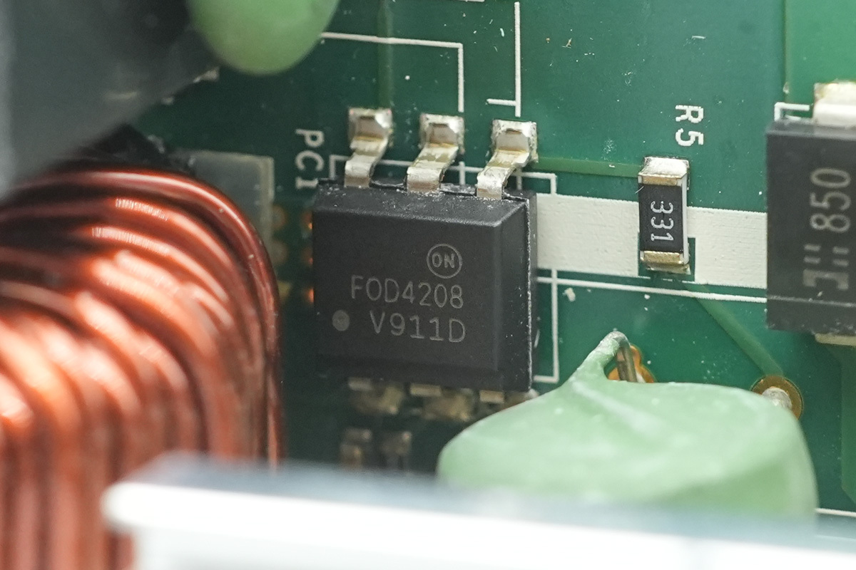
The optocoupler is from onsemi, model FOD4208, specifically configured for TRIAC control.
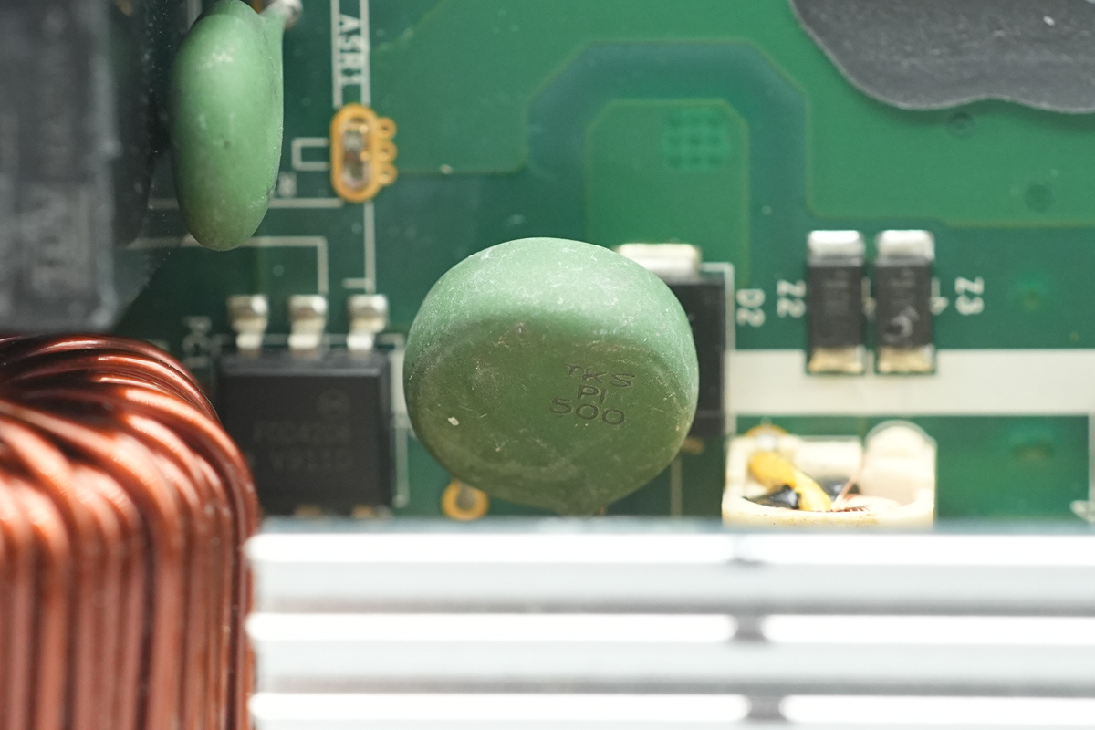
The NTC thermistor is from THINKING, marked TKS PI 500.
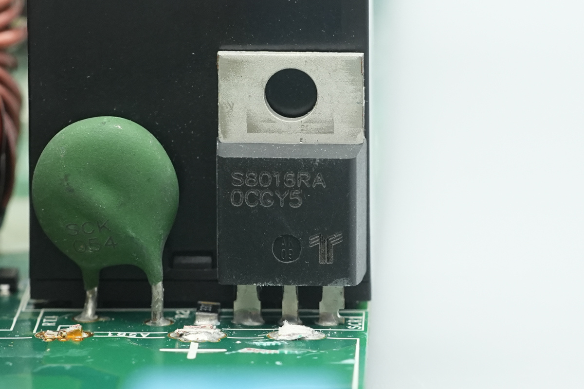
The TRIAC is from Littelfuse, model S8016RA, rated at 800V/16A and housed in a TO-220 package.
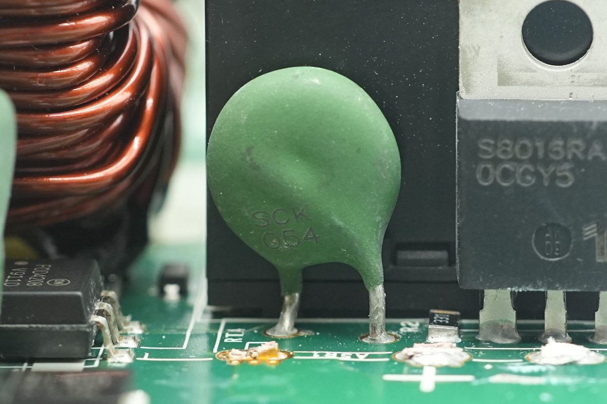
Another NTC thermistor.
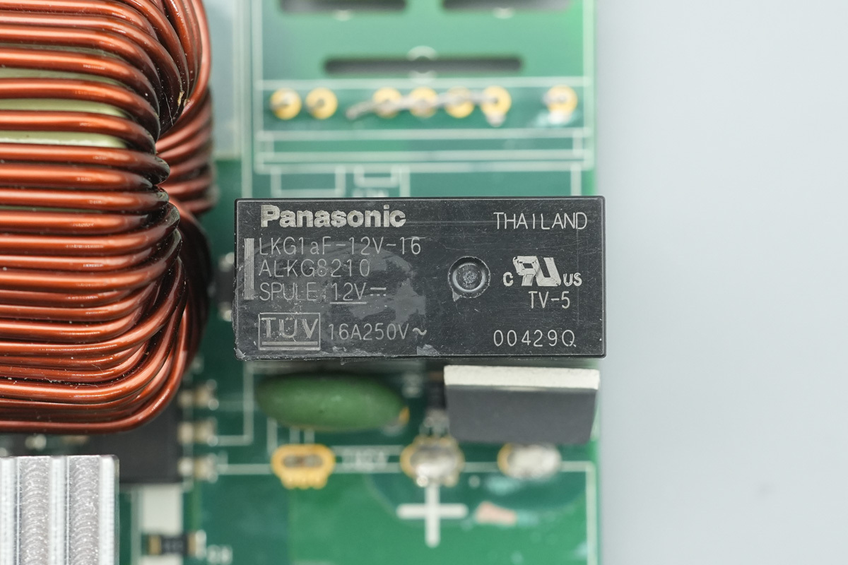
The power relay is from Panasonic, model LKG1aF-12V-16, with a single-pole normally open contact rated for 16A 250V~, and a coil voltage of 12V.
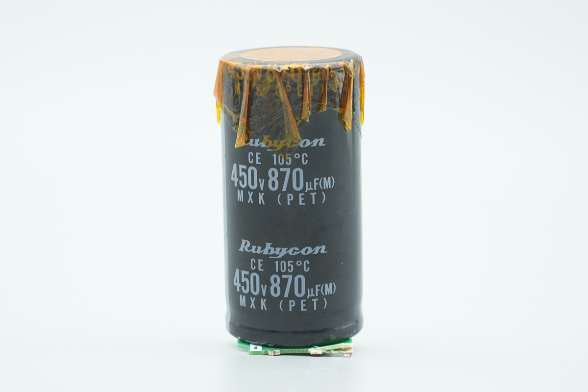
The high-voltage filter cap is from Rubycon, part of the MXK series of ultra-miniature aluminum electrolytic caps, spec 450V/870μF.
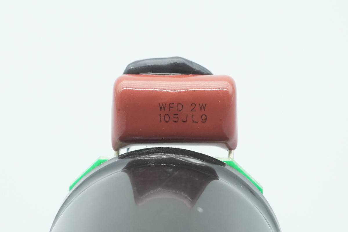
The parallel film cap is from Panasonic, part of the ECWFD series, spec 450V 1μF.
The LLC MOSFETs are mounted on a vertical PCB.
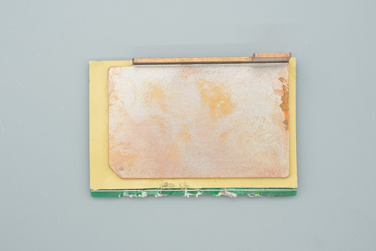
A copper heatsink is attached to the back of the vertical PCB.
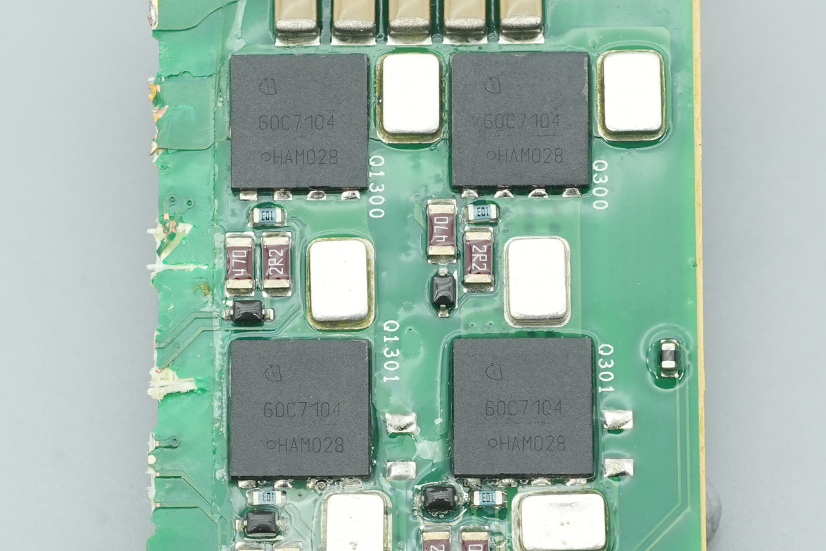
The LLC MOSFETs are from Infineon, marked 60C7104, model IPL60R104C7, part of the CoolMOS C7 series, 650V and 104mΩ, housed in a VSON-4 package.
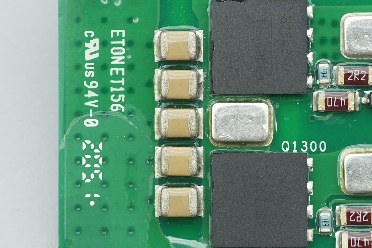
These are five filter MLCCs connected in parallel.
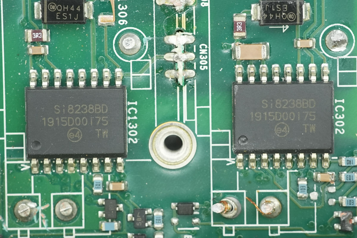
The LLC MOSFET drivers are from Skyworks, model Si8238BD, which are dual-channel isolated drivers with a 4A drive current and 5kVrms isolation, and in a SOIC-16WB packaged.
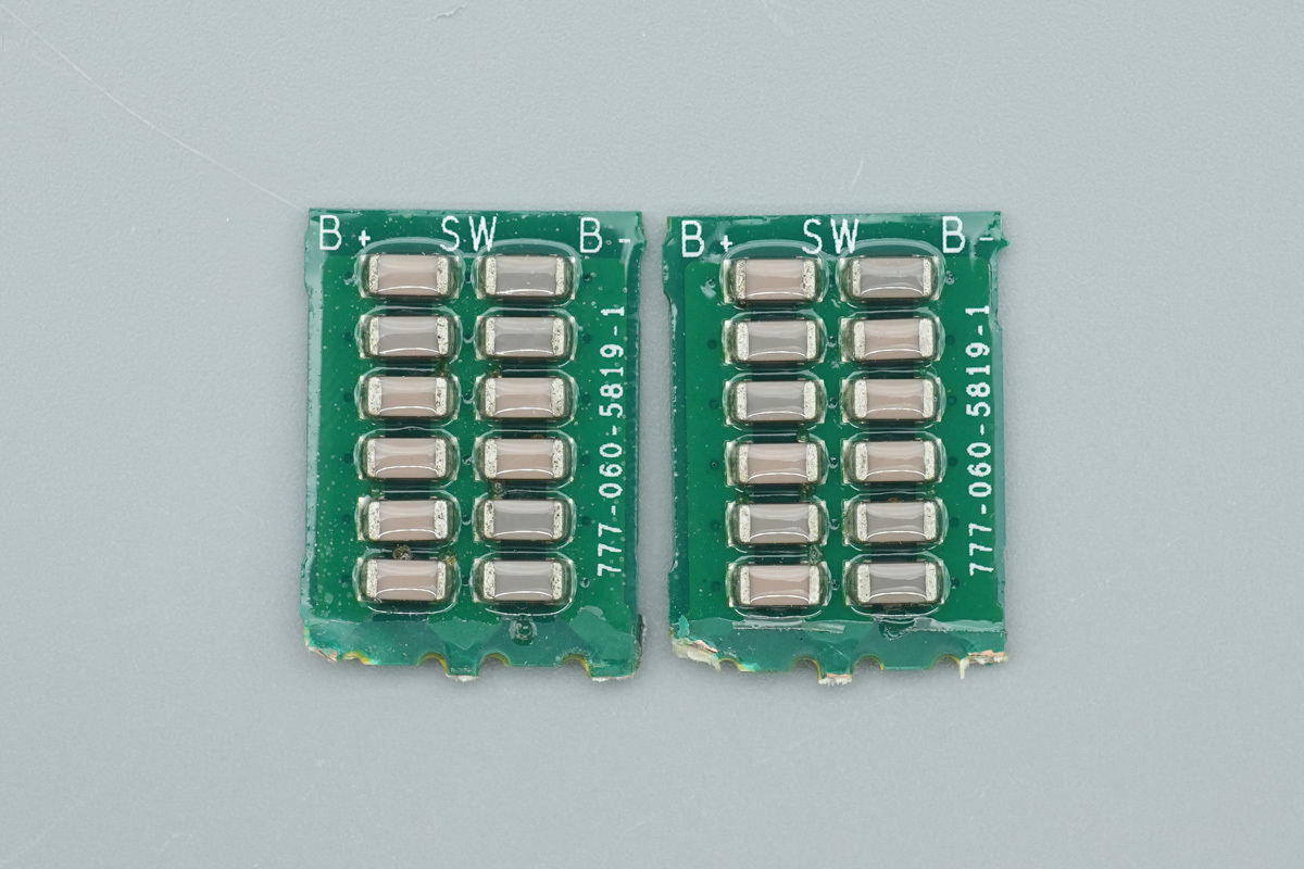
The NPO resonant caps are mounted on the vertical PCBs, arranged in a 6-parallel, 2-series configuration.
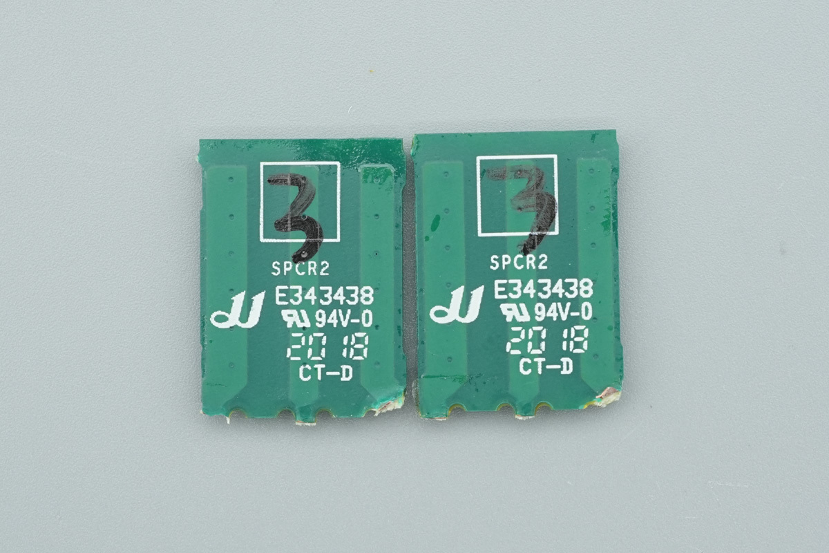
No components on the back of the PCBs.
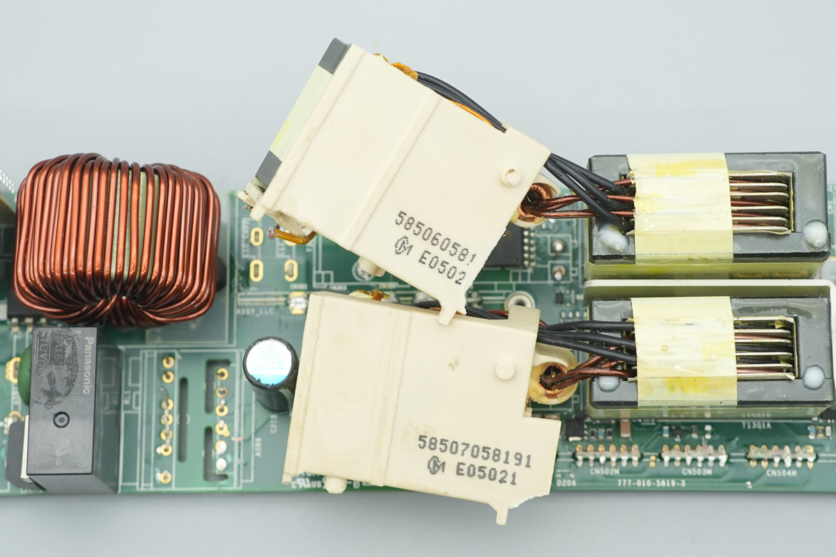
The resonant chokes are housed in plastic casings, featuring current transformers mounted on theirs right.
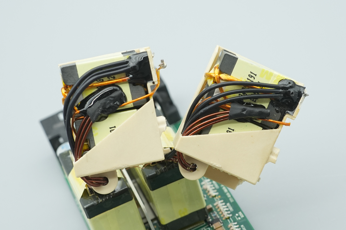
These resonant chokes are wound with Litz wire, with connections secured via soldered joints and reinforced with potting compound.
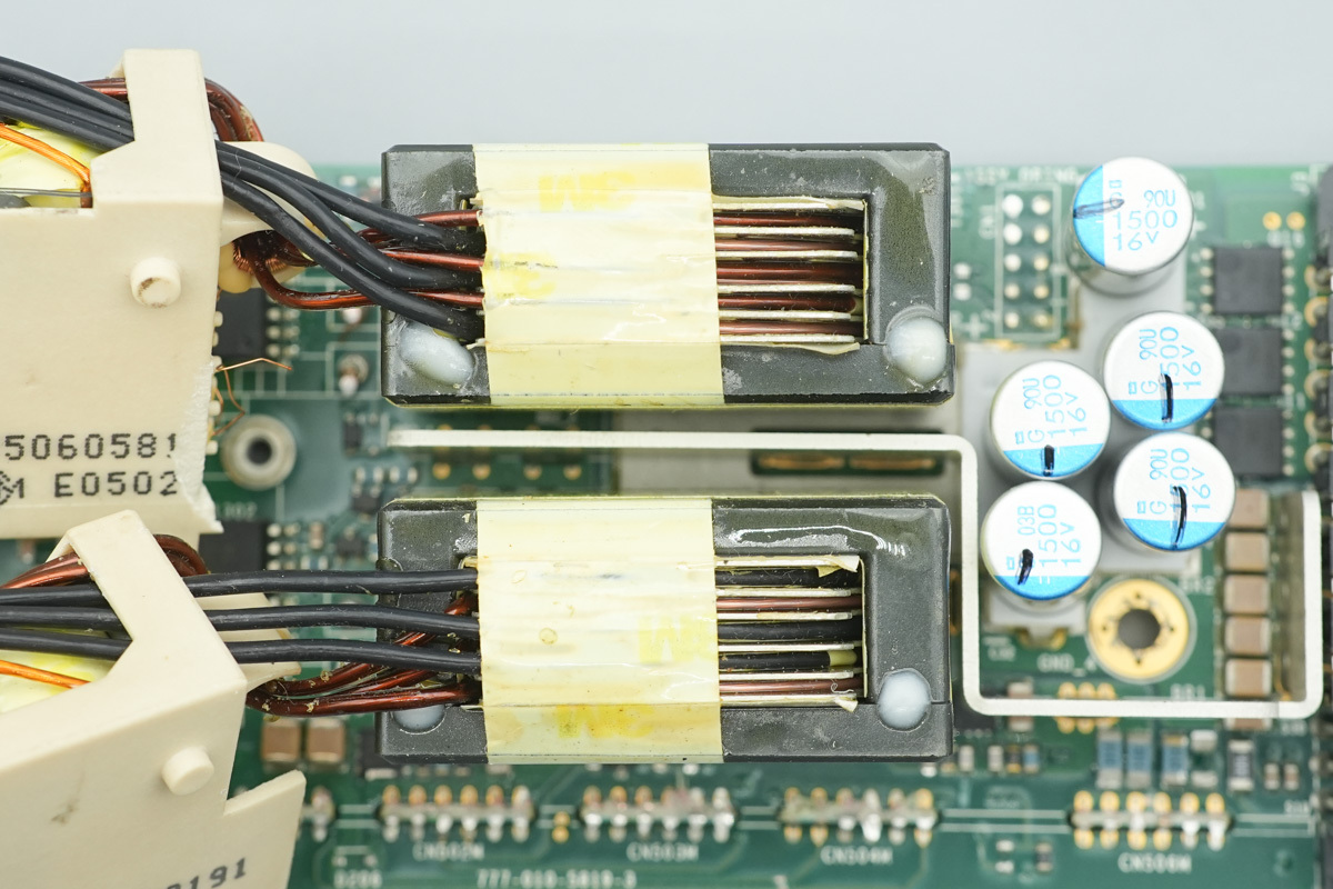
The transformer features primary windings of multi-layer insulated wire and secondary windings terminated with copper foils.
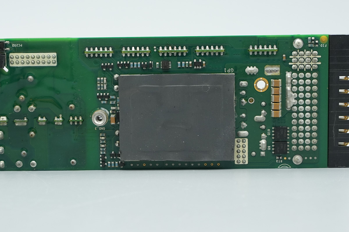
A thermal pad is applied to the synchronous rectifier MOSFETs, utilizing the enclosure as a heat spreader to facilitate thermal dissipation.
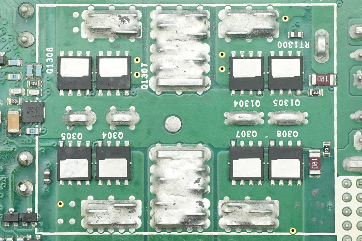
Eight synchronous rectifier MOSFETs are mounted on the back of the transformer.
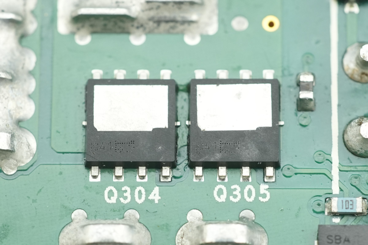
The synchronous rectifier MOSFETs are from Toshiba, model TPWR8004PL, marked K41, NMOS, 40V and 0.65mΩ, housed in a DSOP Advance package.
The device features thermal pads on both the top and bottom, enabling a dual-sided cooling design. In this application, the top pad is coupled to the enclosure via a thermal pad to facilitate heat dissipation.
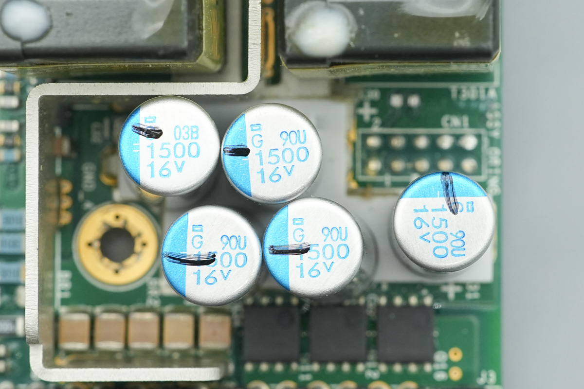
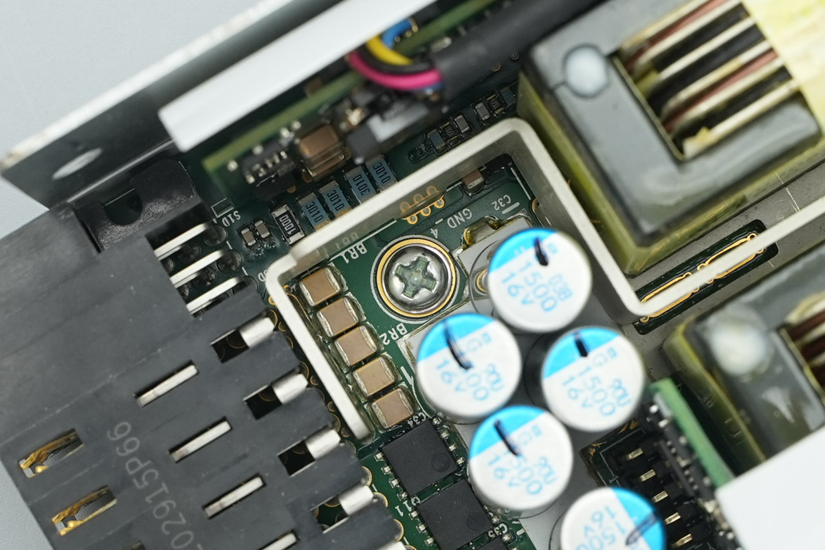
The filter caps are from NCC, specifically the PSG series of conductive polymer aluminum solid electrolytic caps. These devices feature ultra-low ESR and high ripple current ratings, with a rated endurance of 15,000 to 20,000 hours at 105°C. The configuration utilizes five 1500μF/16V caps in parallel to handle output filtering.
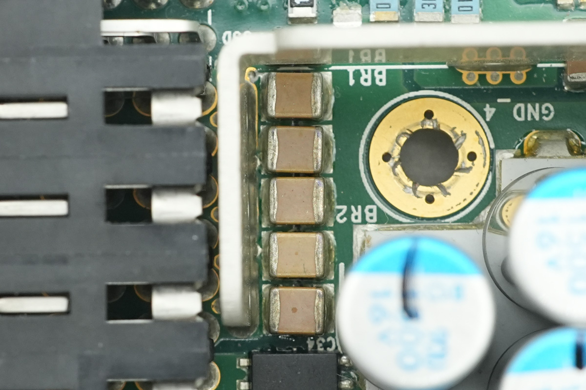
The MLCCs are utilized for output filtering, all in 1210-packages.

The backside also features five 1210 MLCCs.
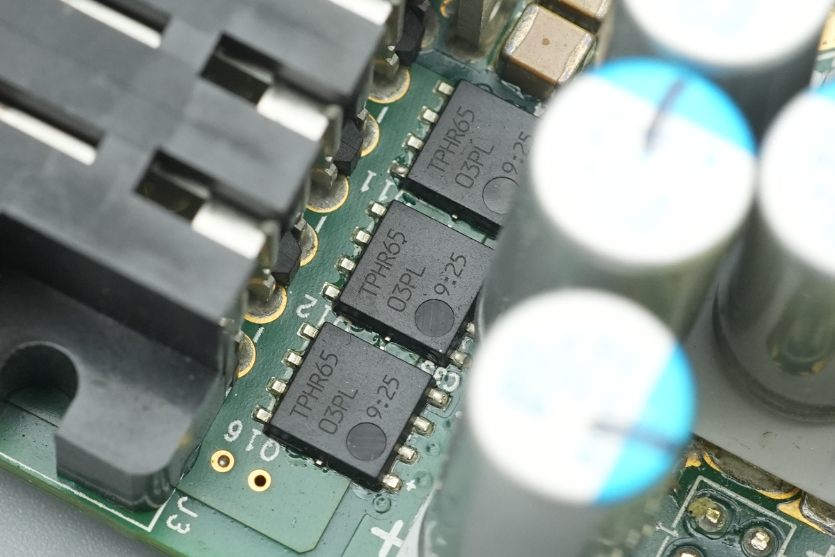
The output control MOSFETs are from Toshiba, model TPHR6503PL, NMOS, 30V and 0.41mΩ, housed in the SOP Advance packages.
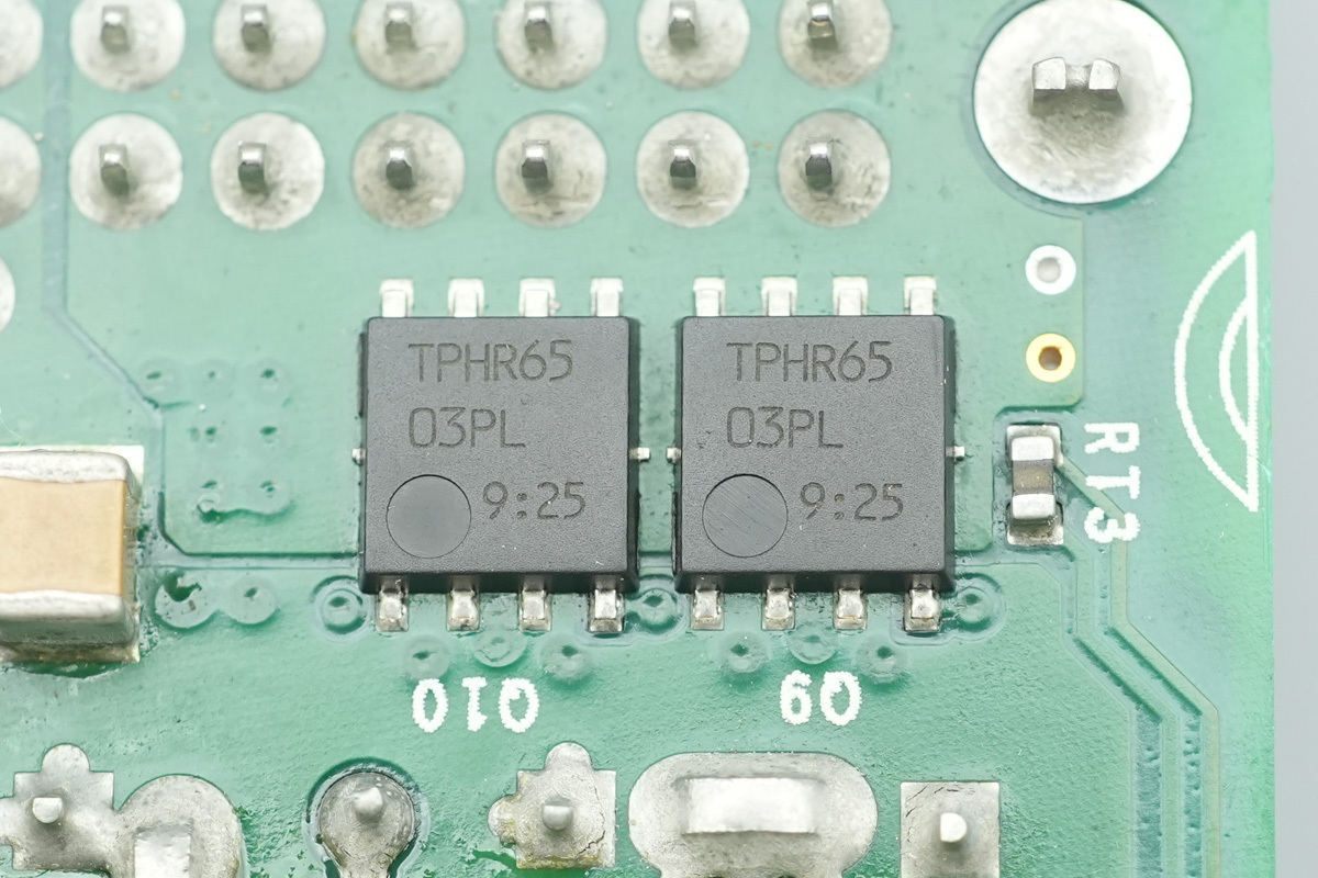
Two output control MOSFETs of the same model are mounted on the backside.
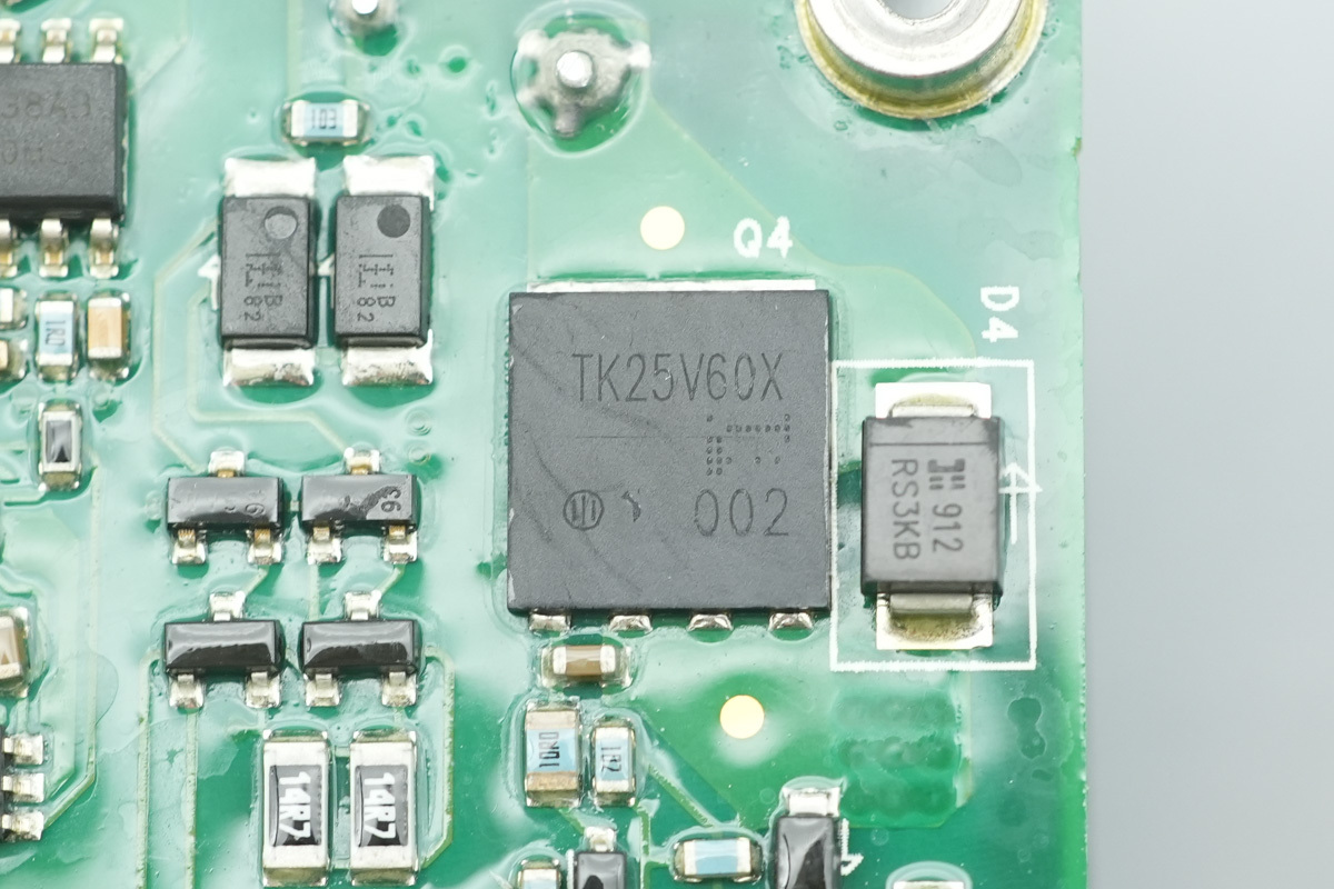
The power MOSFET is sourced from Toshiba, model TK25V60X, NMOS, 600V and 110mΩ, in a DFN 8x8 package.
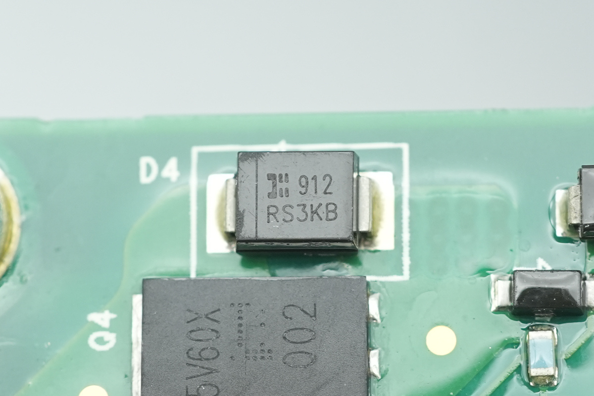
The diode is from Diodes Inc., model RS3KB, spec 800V and 3A, housed in an SMB package.
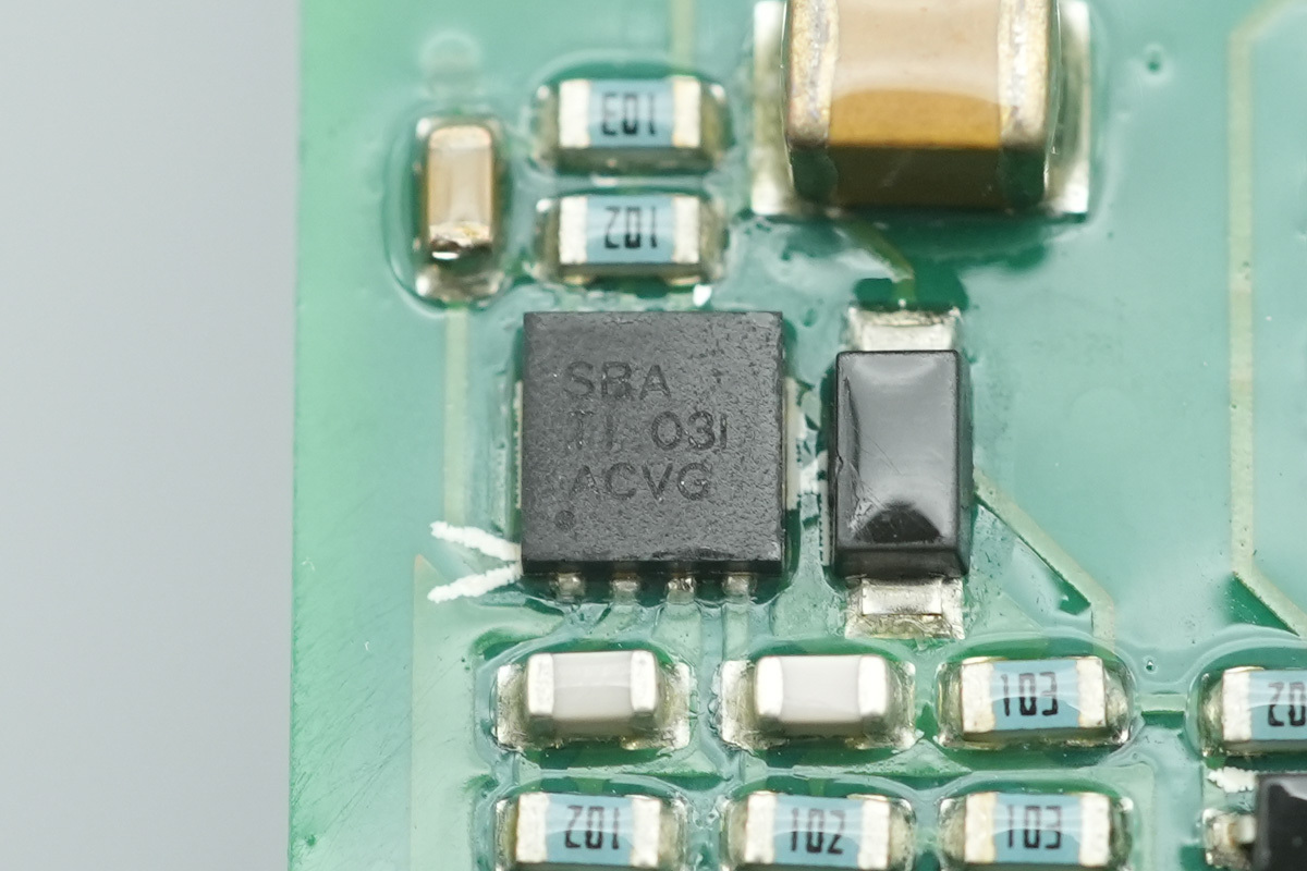
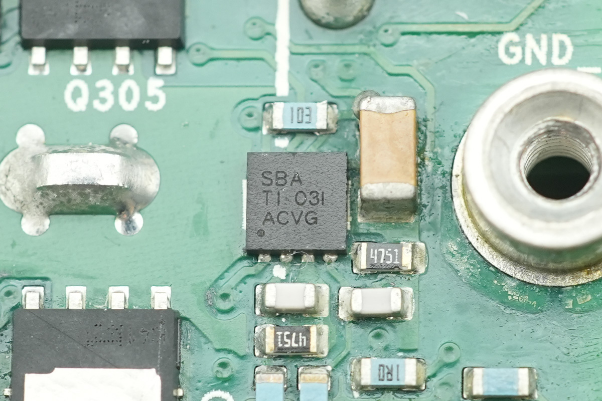
The gate driver is from TI, model UCC27524, marked SBA. It is a dual-channel, 5A high-speed, low-side gate driver capable of handling negative input voltages, supporting an operating voltage range of 4.5V to 18V, housed in a WSON8 package.
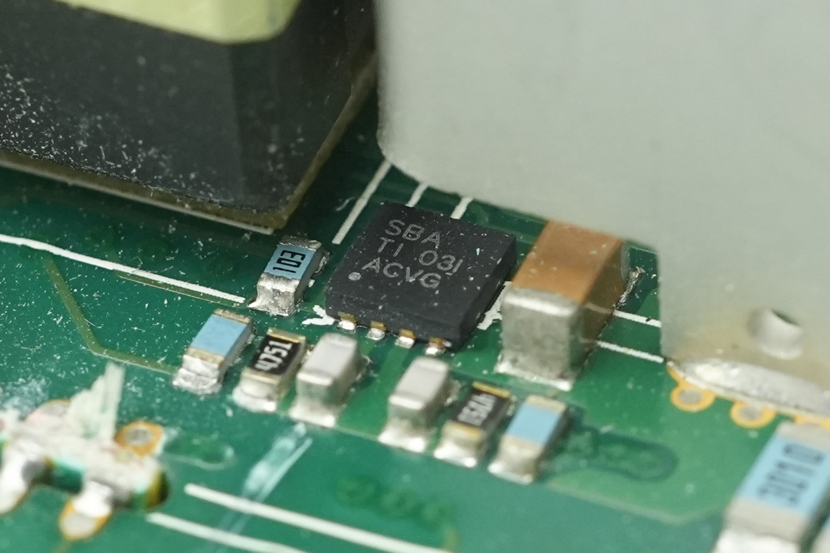
It is specifically employed to drive the synchronous rectifier MOSFETs.
The back of the PCBA has a driver of the same model.
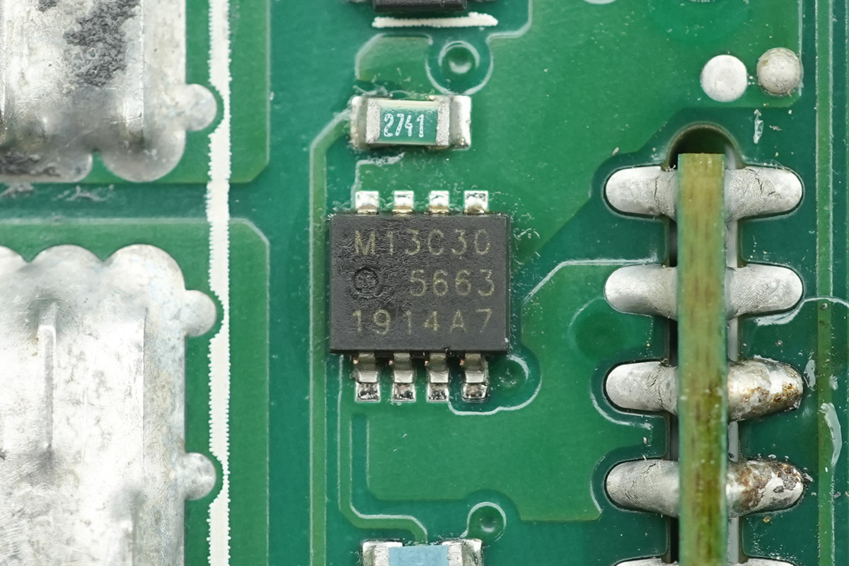
The VBUS MOSFET is from Nexperia, model PSMN013-30MLC, marked M13C30, NMOS, 30V and 13.6mΩ, housed in the LFPAK33 package.
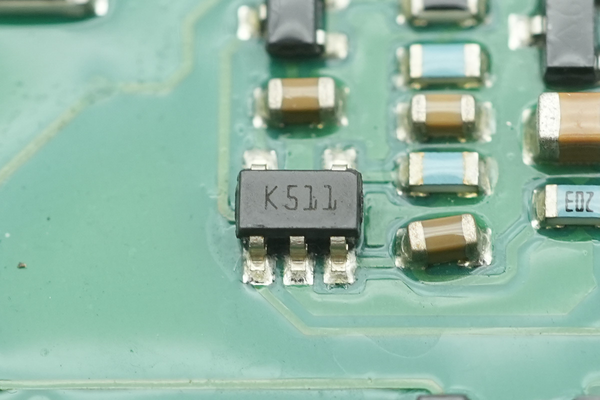
The voltage comparator is from ST, model TS391ILT, marked K511. This is a low-power, single-channel voltage comparator housed in a SOT23-5 package.
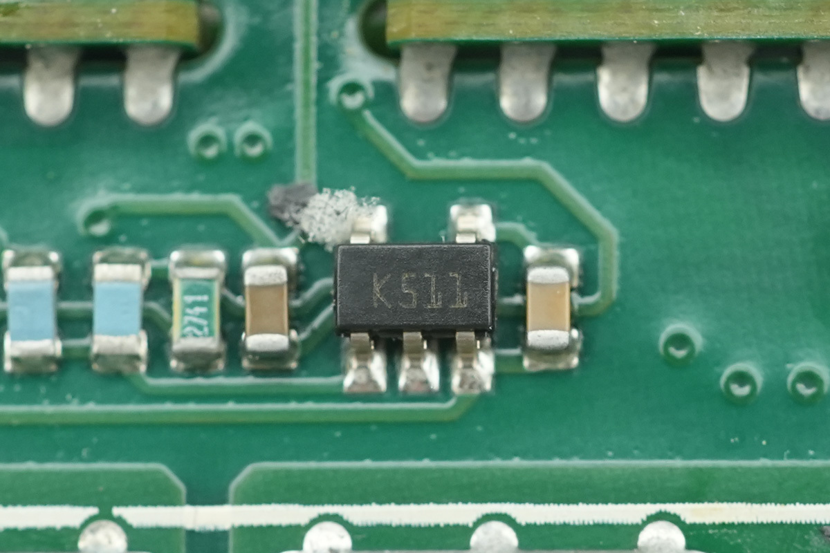
Another one shares the same model.
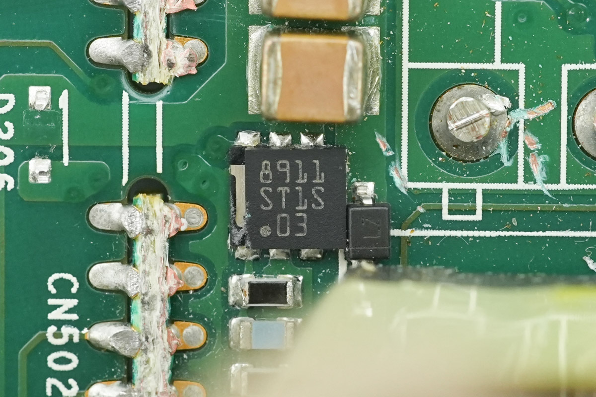
The step-down chip is from ST, model ST1S03. This switching regulator supports a 16V input capability, 1.5A output, and a 1.5MHz switching frequency in a DFN6D package.
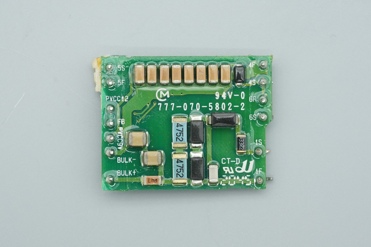
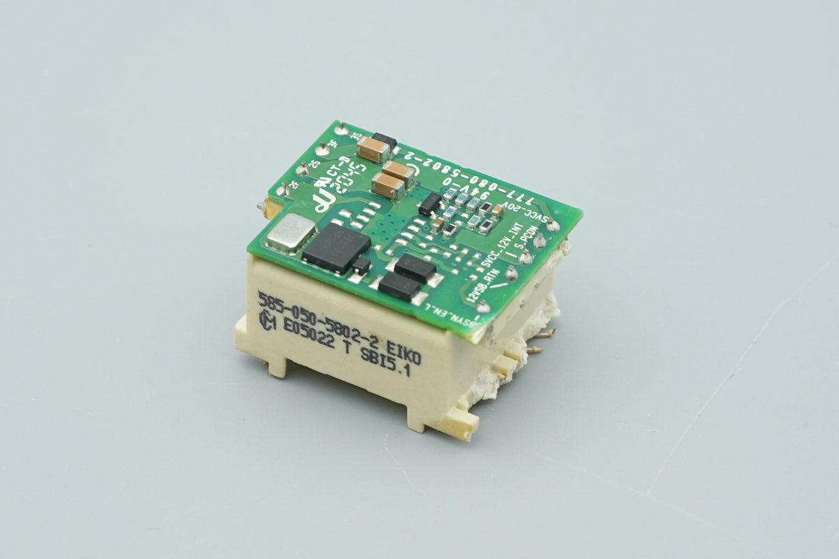
The standby power supply PCB is soldered to the transformer, and the PCB has a snubber circuit and the MLCCs.
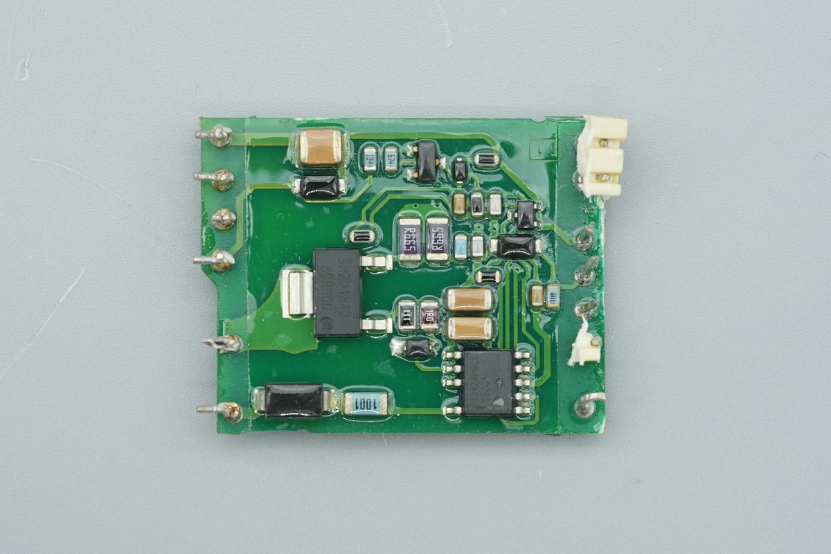
The opposite side houses the standby controller IC and the MOSFET.
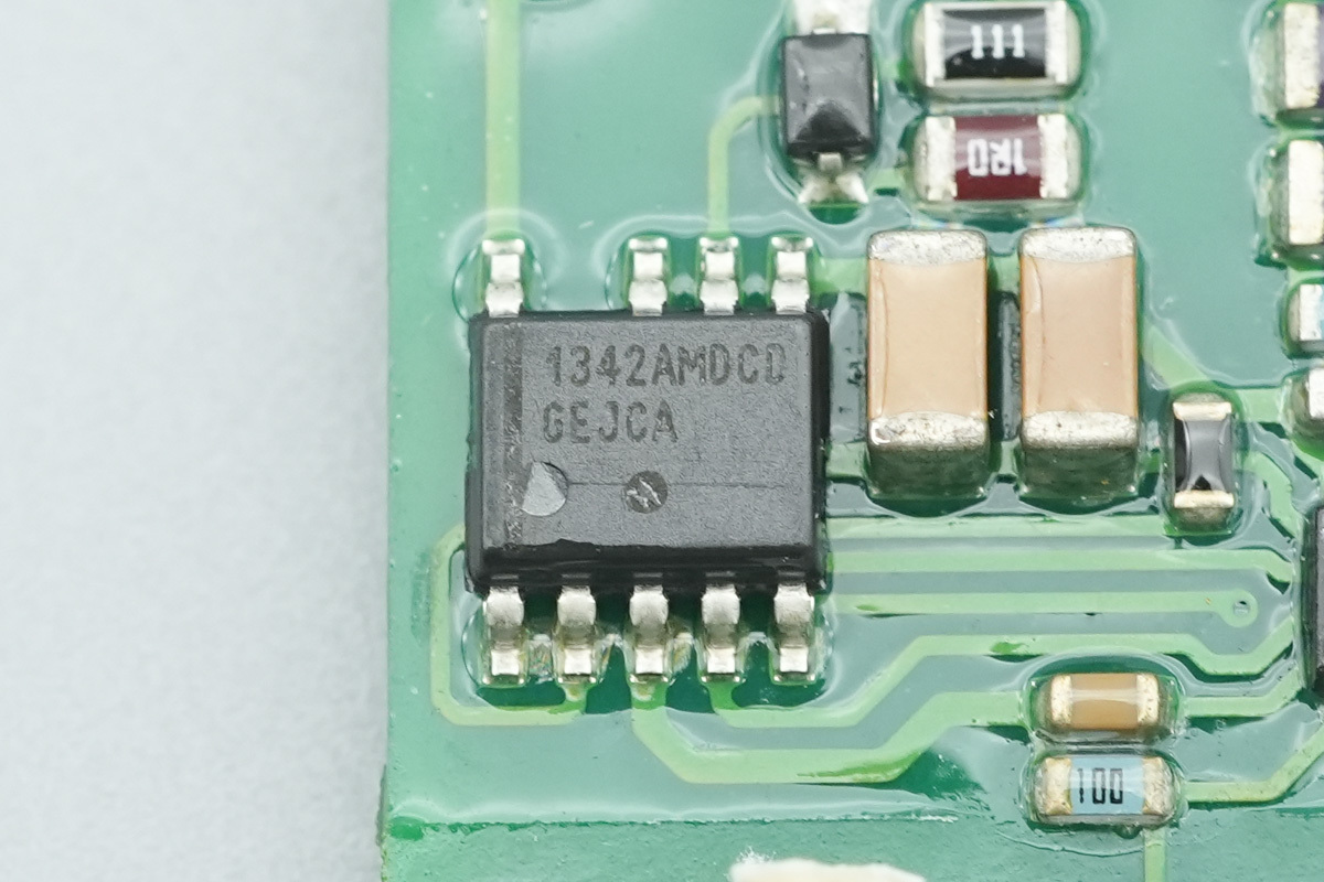
The standby controller IC is from onsemi, model NCP1342A. It is a high-performance quasi-resonant flyback controller that integrates an X2 cap discharge function to meet safety requirements, housed in a SOIC-9 NB package.
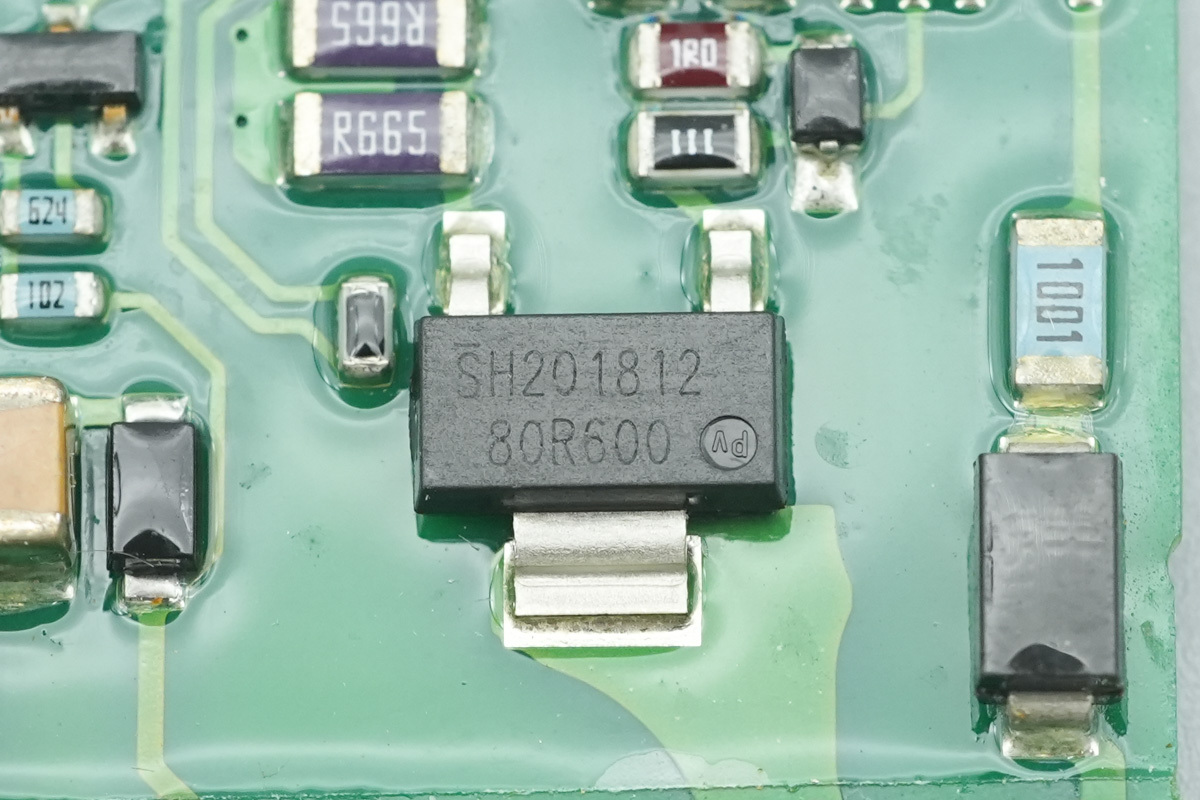
The power MOSFET is from Infineon, model IPN80R600P7, marked 80R600, NMOS, 800V and 600mΩ, housed in the SOT223 package.
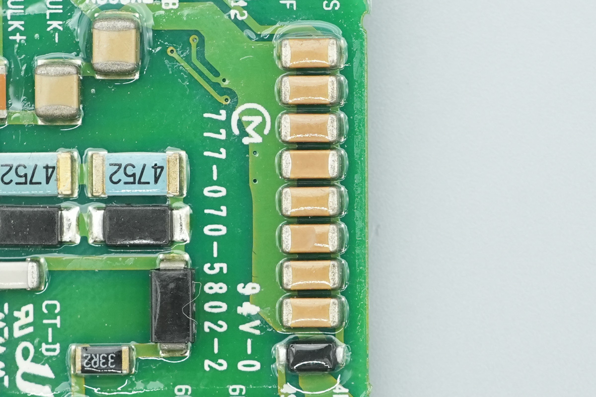
Here are the filter MLCCs.
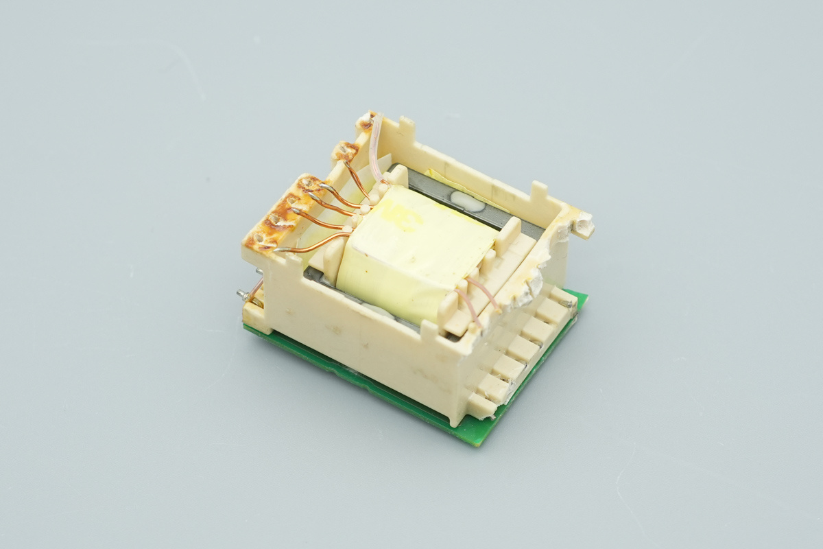
The transformer is equipped with an insulating plastic casing.
The opposite side of the insulating casing features the soldered PCB.
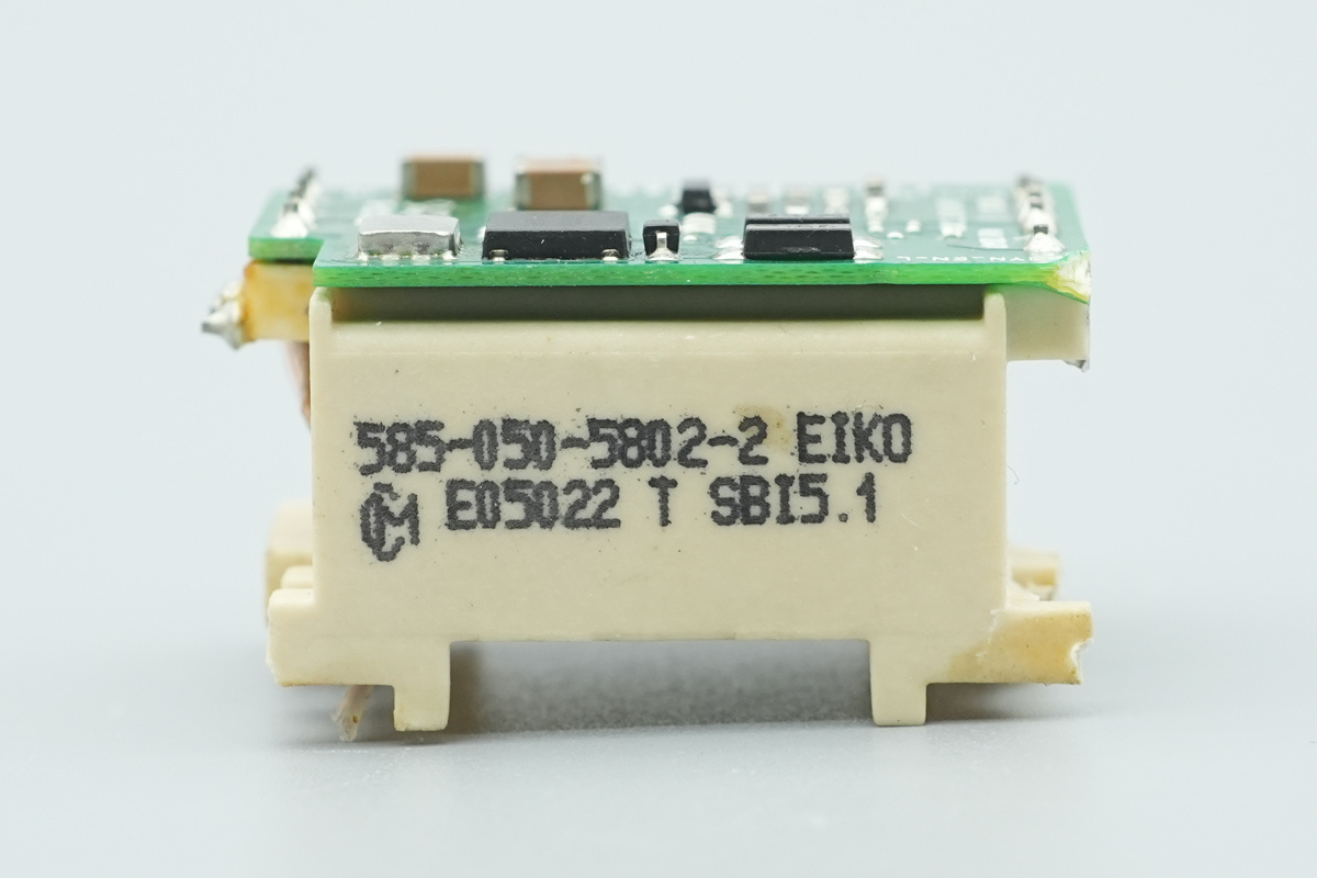
The side of the transformer casing features silkscreen markings.
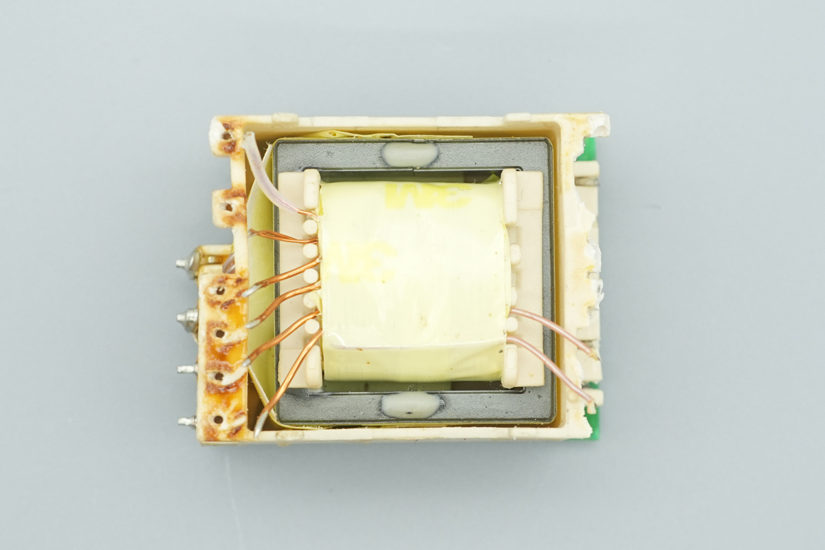
The transformer is insulated by the plastic casing.
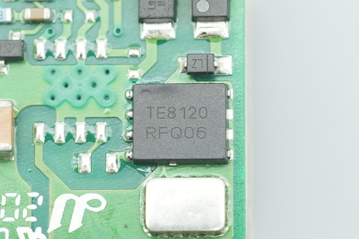
The power rectifier MOSFET is from onsemi, marked TE8120, housed in a DFN-5 package.
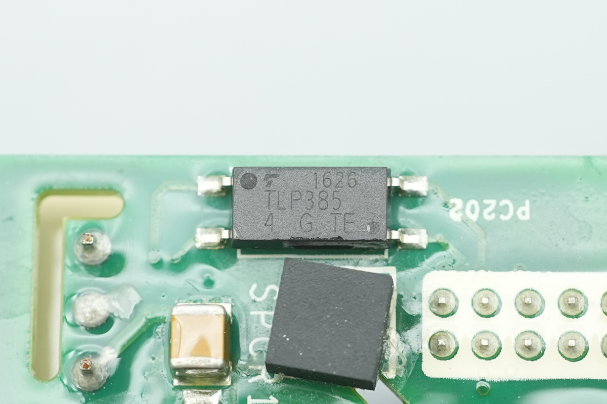
A optocoupler is from Toshiba, model TLP385, for output voltage feedback.
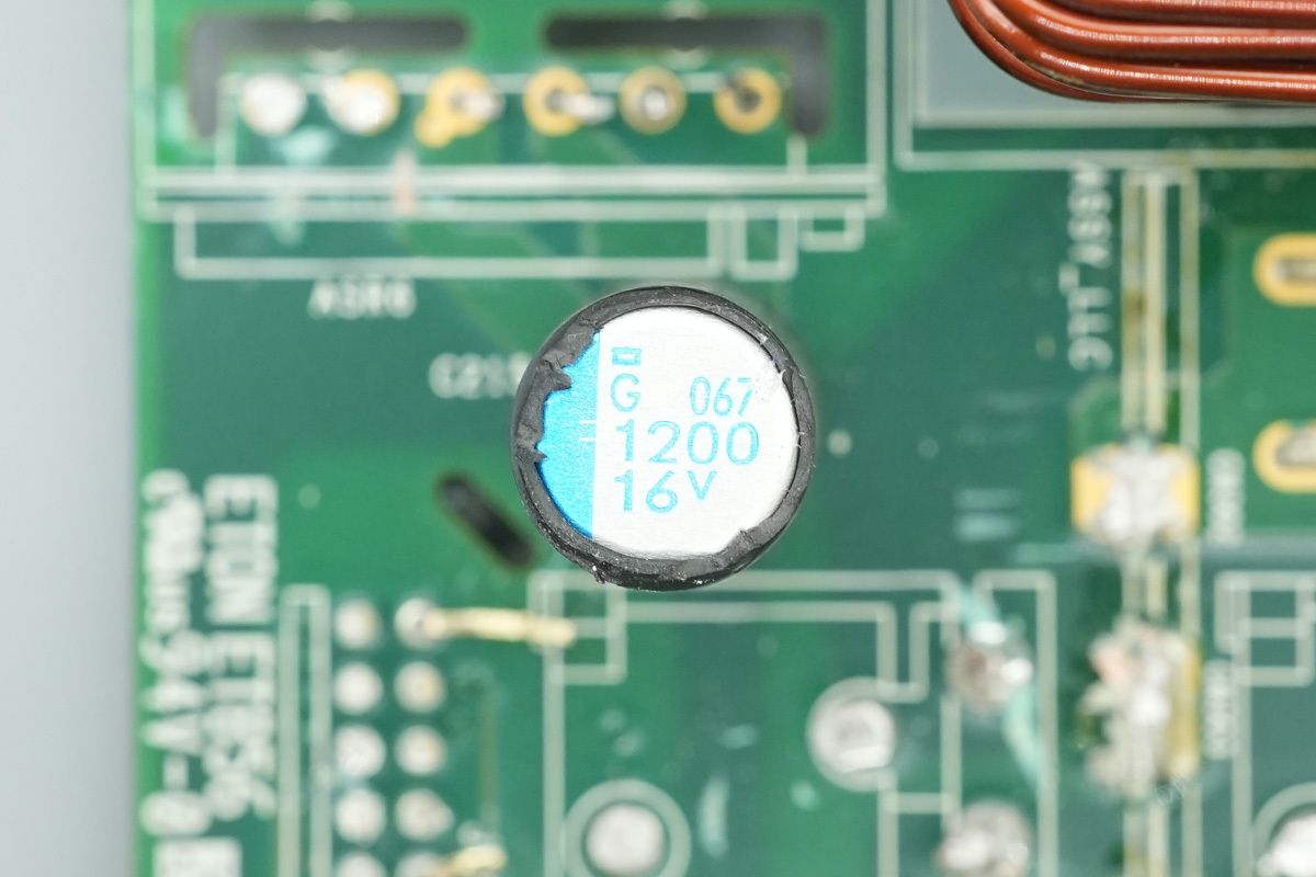
The low-voltage filter cap is from NCC, 1200μF16V.
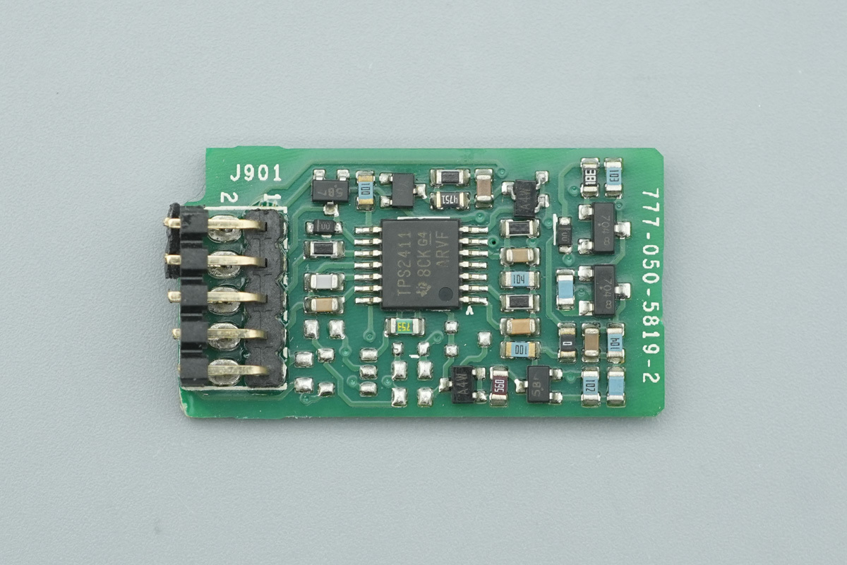
The OR-ing controller is mounted on a dedicated, standalone PCB.
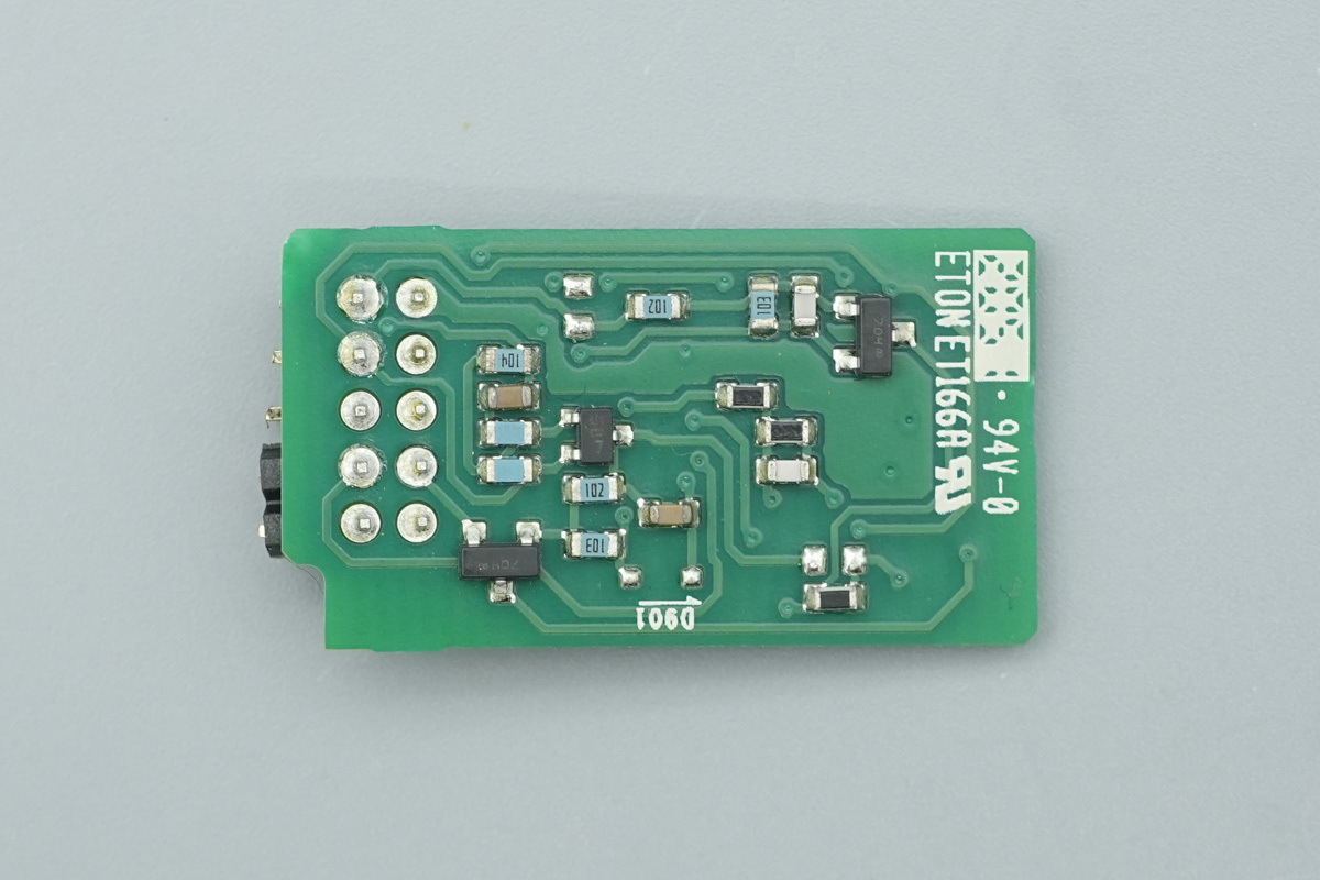
The back of the PCB is densely populated with resistors and capacitors.
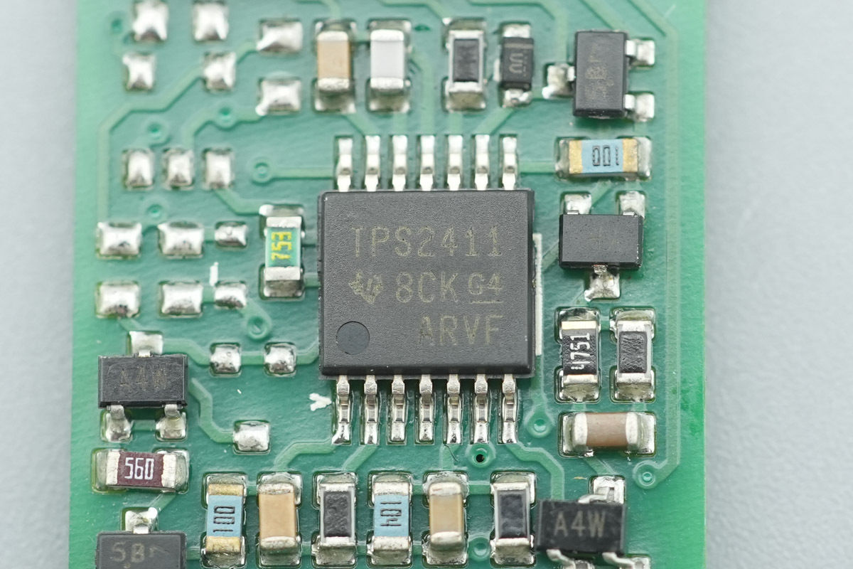
The OR-ing controller is from TI, model TPS2411. It is a full-featured N+1 and ORing power rail controller designed to manage supply redundancy. It supports a wide operating input range of 0.8V to 16.5V and is housed in a TSSOP14 package.
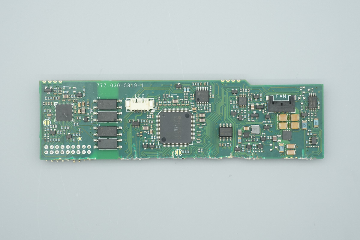
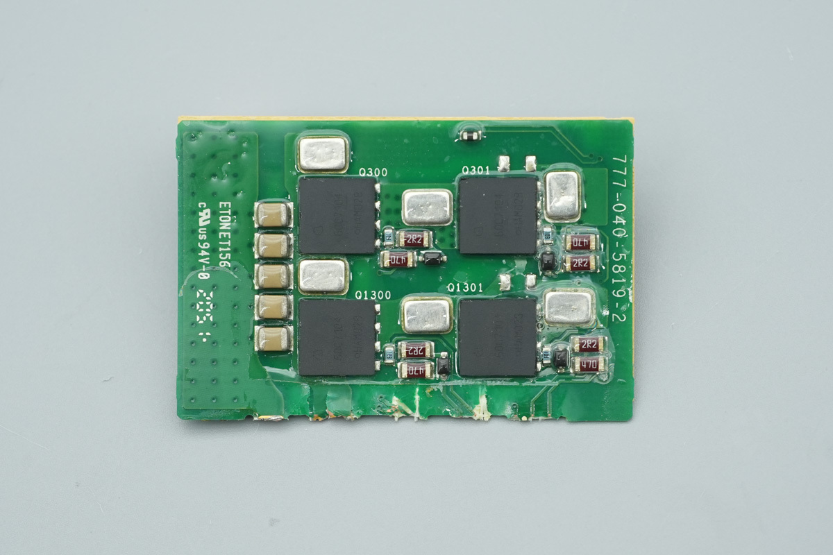
The outer side of the control PCB is equipped with a PFC control chip, communication optocouplers, an LLC control chip, the memory chips, operational amplifiers, a synchronous step-down chip, and voltage comparators.
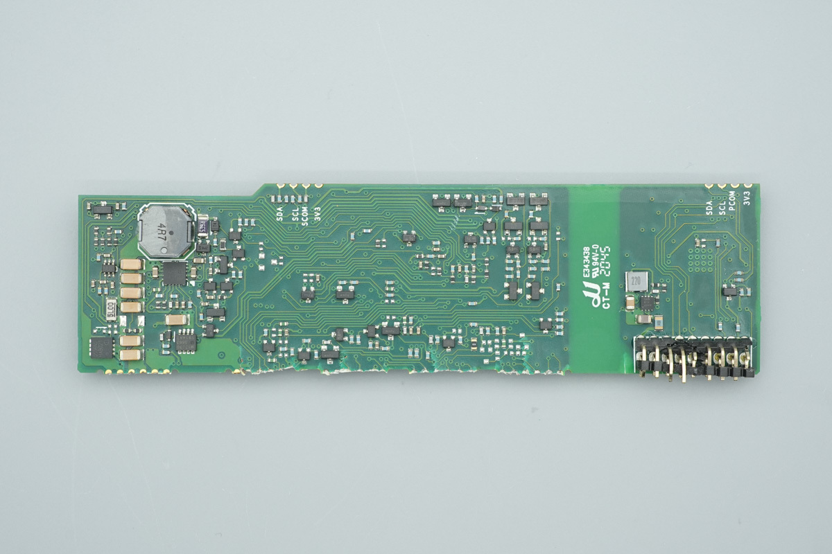
The back of the PCB is populated with a synchronous step-down chip, the step-down chokes, a current sense chip, and power control MOSFETs.
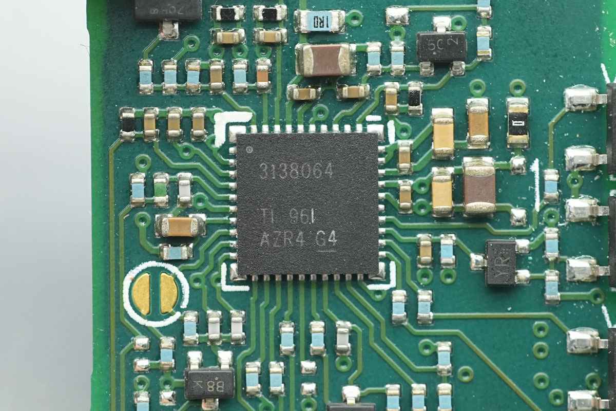
The PFC control chip is from TI, model UCD3138064. It is a digital power controller featuring an integrated 64KB flash memory, SPI and I2C interfaces, and support for a wide range of topologies including phase-shifted full-bridge, single-phase and interleaved PFC, bridgeless PFC, hard-switched full-bridge and half-bridge, as well as half-bridge and full-bridge LLC. The device is housed in a VQFN64 package.
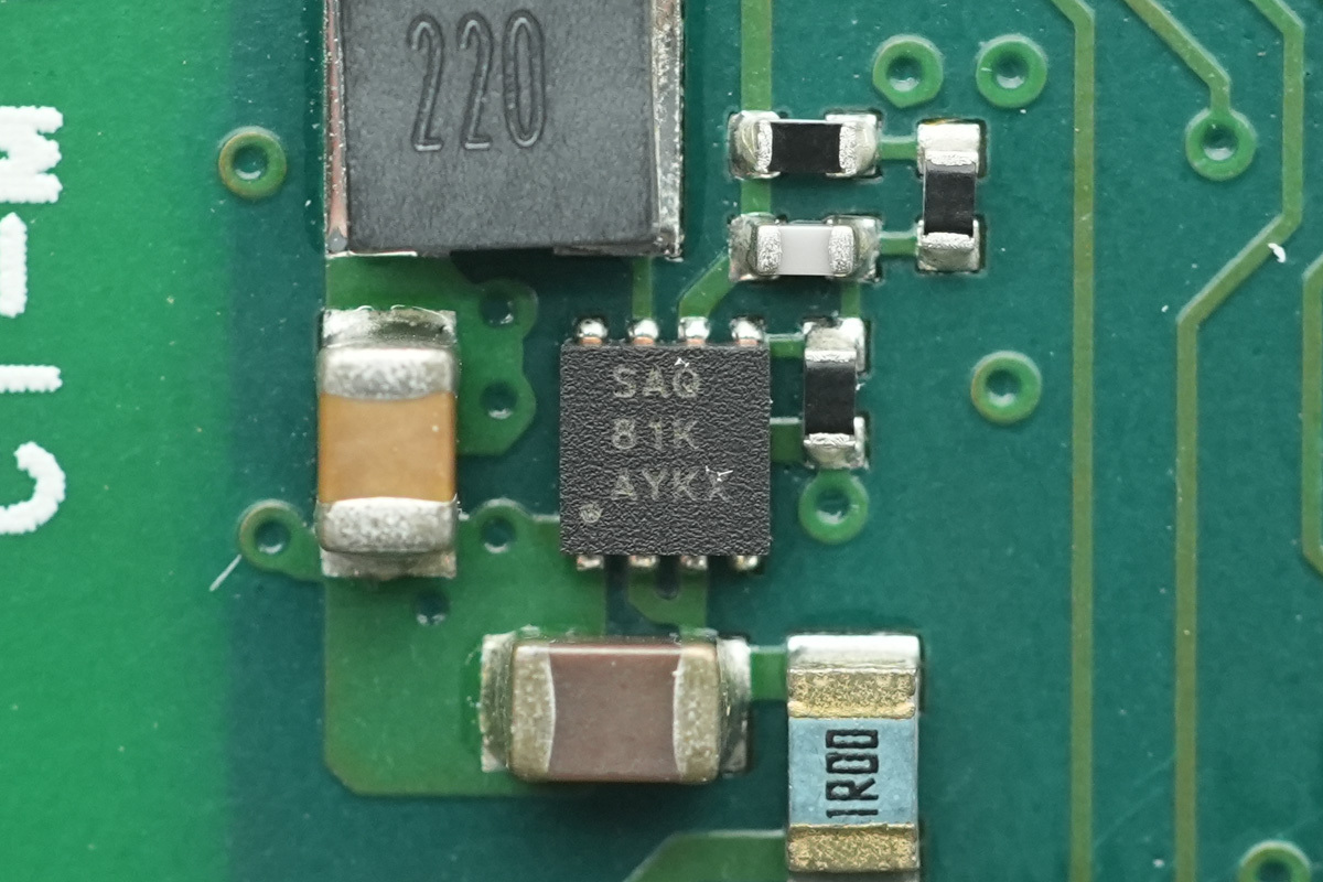
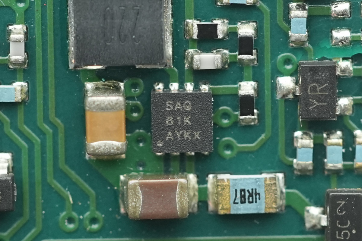
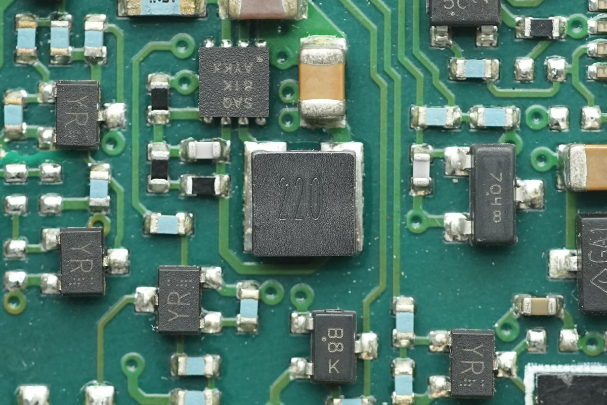
The synchronous step-down chip is from TI, marked SAQ, model TPS65125. It is a synchronous step-down converter featuring adjustable enable threshold and hysteresis, capable of handling a 3V to 17V input voltage range with a 300mA output current, and in a WSON8 package.
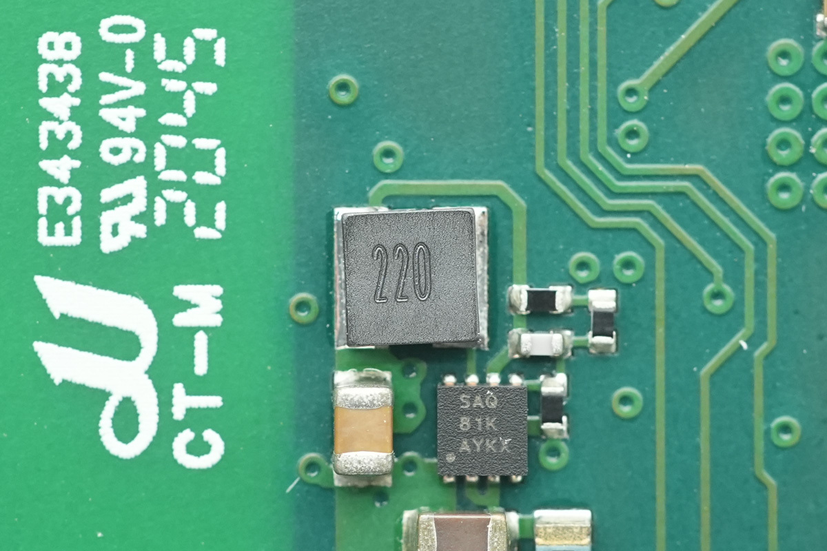
The choke, 22 μH.
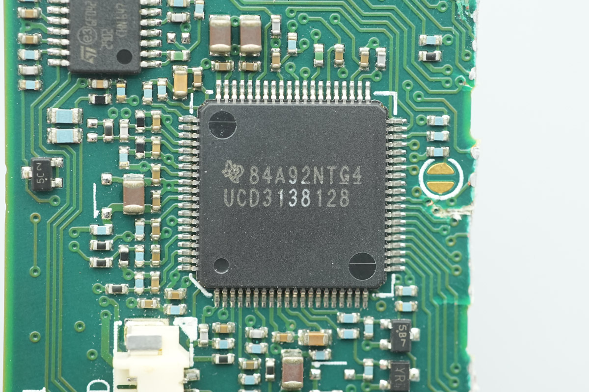
The LLC control chip is from TI, model UCD3138128. It is a digital power controller featuring an integrated 128KB flash memory, SPI and I2C interfaces, and support for a wide range of topologies, including phase-shifted full-bridge, single-phase and interleaved PFC, bridgeless PFC, hard-switched full-bridge and half-bridge, as well as half-bridge and full-bridge LLC, and housed in a TQFP80 package.
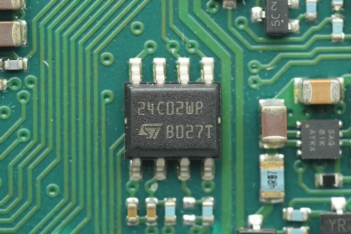
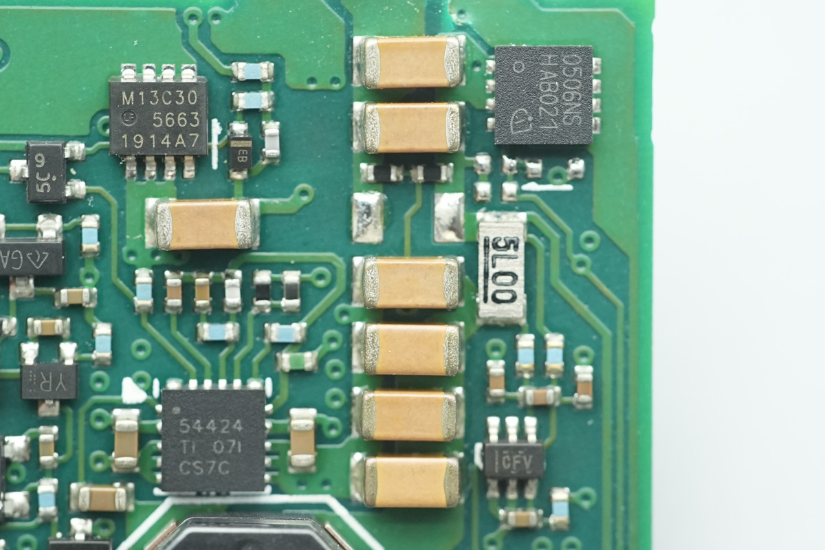
The memory chip is from ST, model M24C02-W. It offers a capacity of 256 bytes, supports an operating voltage range of 1.7V to 5.5V, in an SO8N package.
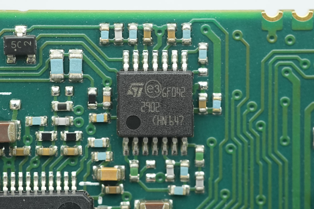
The operational amplifier is from ST, model LM2902. It is a low-power quad operational amplifier, provided in a TSSOP14 package.
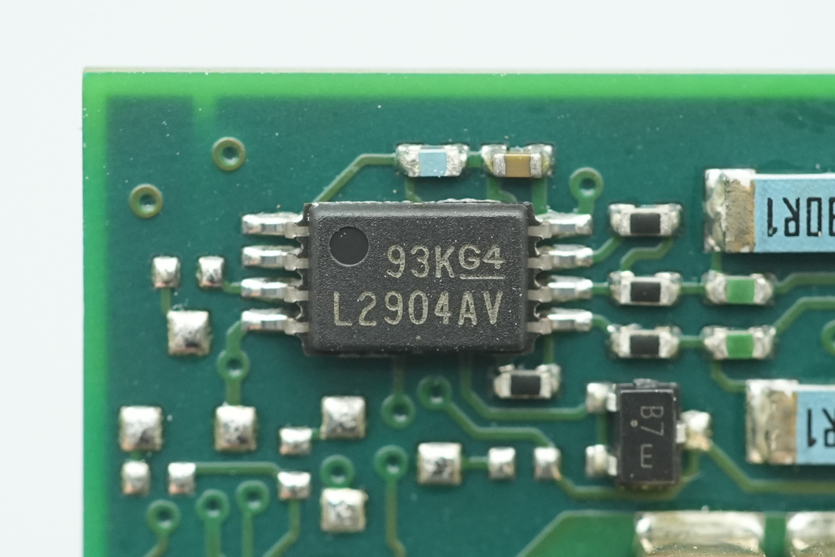
The operational amplifier is from TI, model LM2904AV. It is an industry-standard dual operational amplifier, provided in a TSSOP8 package.
The synchronous step-down chip is from TI, model TPS65125.
The step-down choke, 22μH.
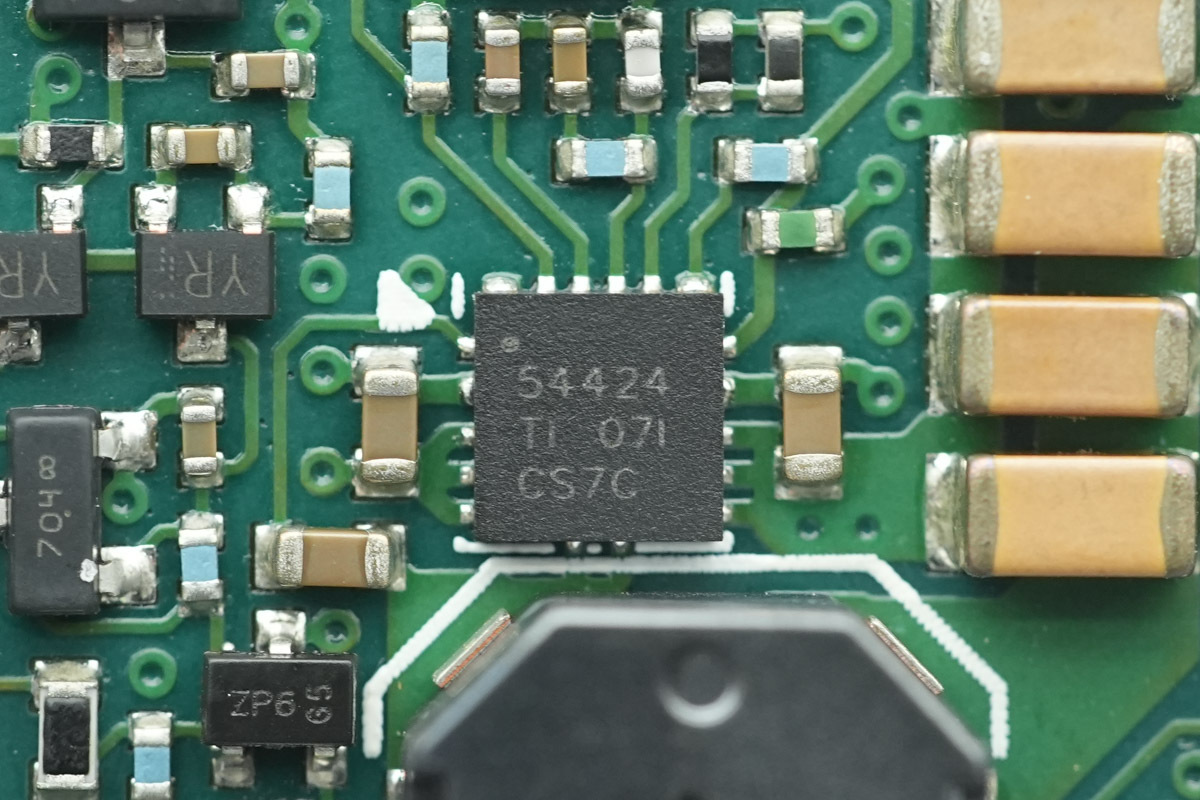
The synchronous step-down chip is from TI, model TPS54424. It is a current-mode synchronous step-down converter featuring an input voltage range of 4.5V to 17V, an adjustable output voltage range of 0.6V to 12V, and a maximum output current of 4A, and in a VQFN-HR18 package.
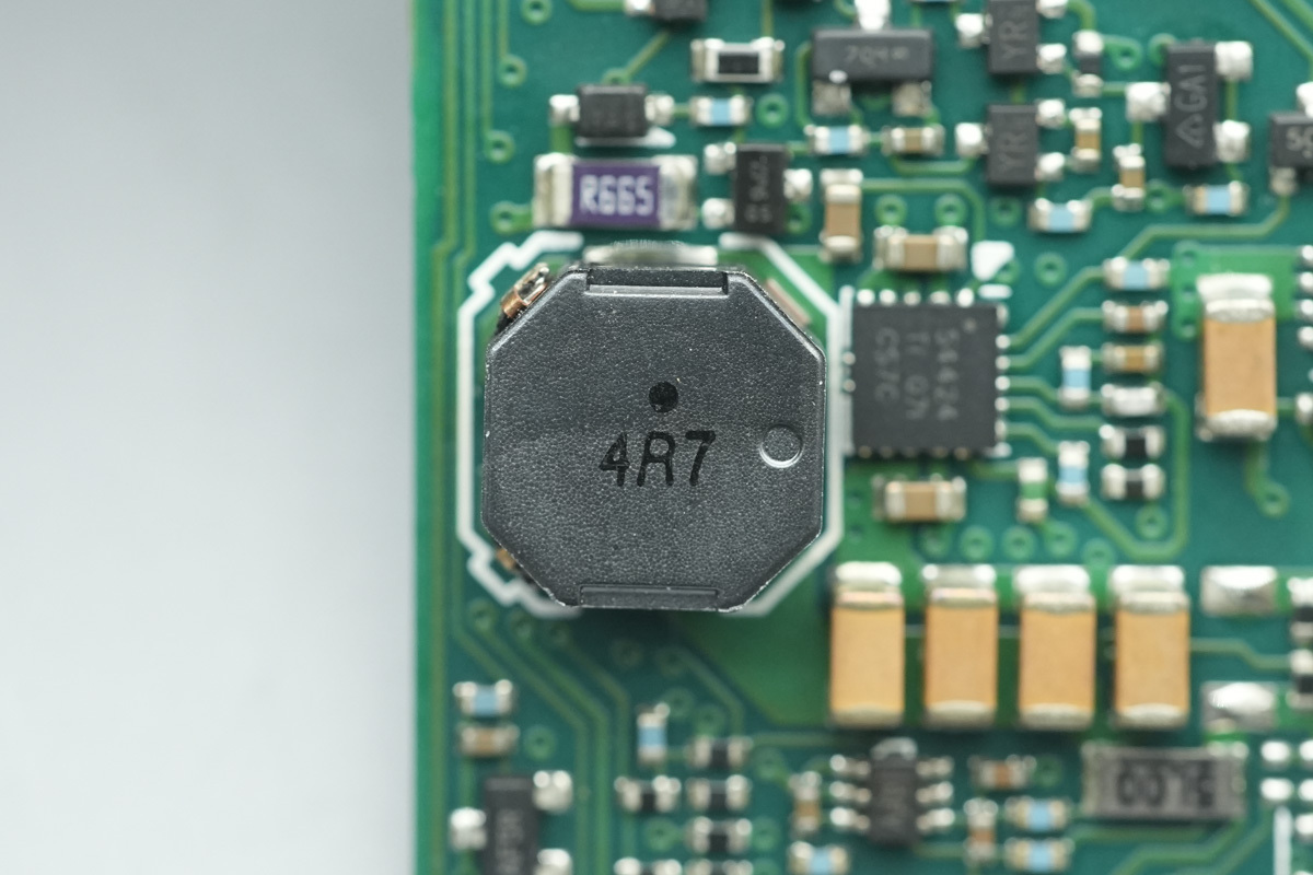
The step-down choke, 4.7μH.
The filter MLCCs.
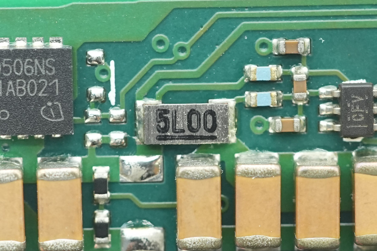
This is a 5mΩ current sense resistor.
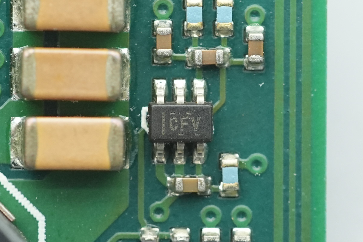
The current sense chip is from TI, marked CFV, model INA214A. It supports an operating supply voltage range of 2.7V to 26V and is in an SC70 package.
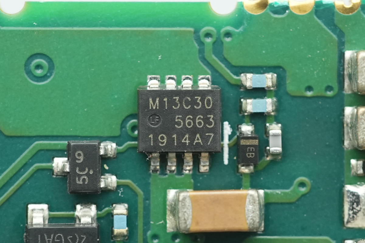
The VBUS MOSFET is from Nexperia, model PSMN013-30MLC.
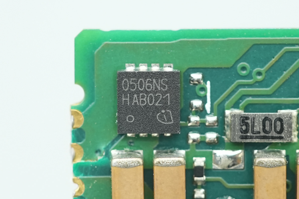
The VBUS MOSFET is from Infineon, model BSZ0506NS, NMOS, 30V and 4.4mΩ, and in a TSDSON-8 FL package.
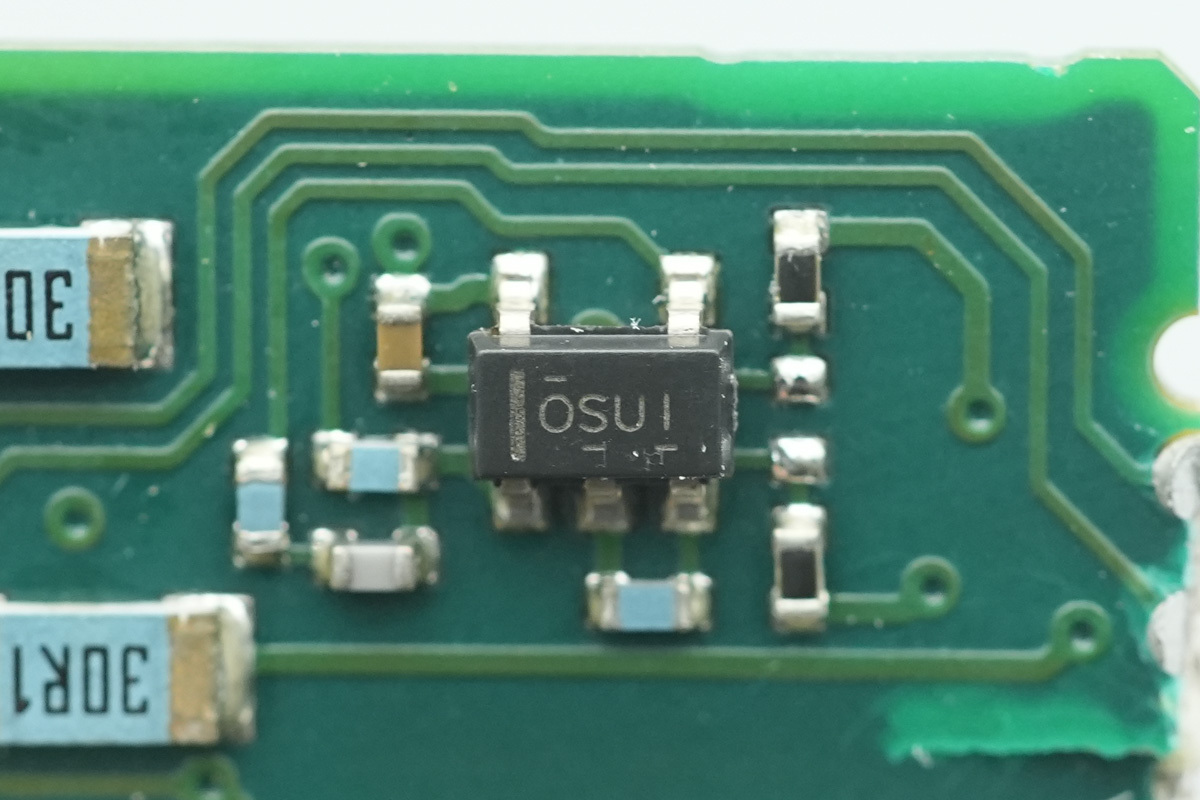
The operational amplifier is from TI, marked OSUI, model OPA171. It is a 36V, single-supply, general-purpose operational amplifier, in a SOT-23 package.
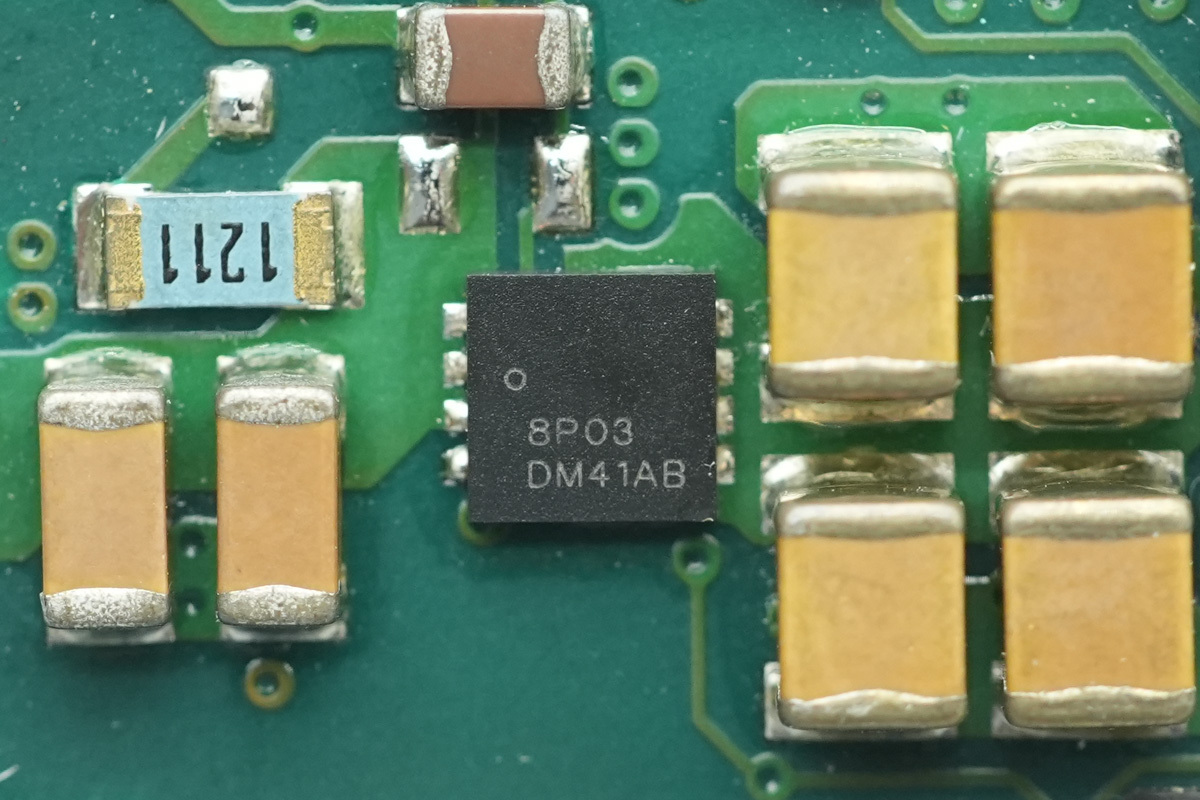
The power control MOSFET is from onsemi, marked 8P03, model NTTFS008P03P8Z, PMOS, -30V and 3.8mΩ, housed in a WDFN8 package.
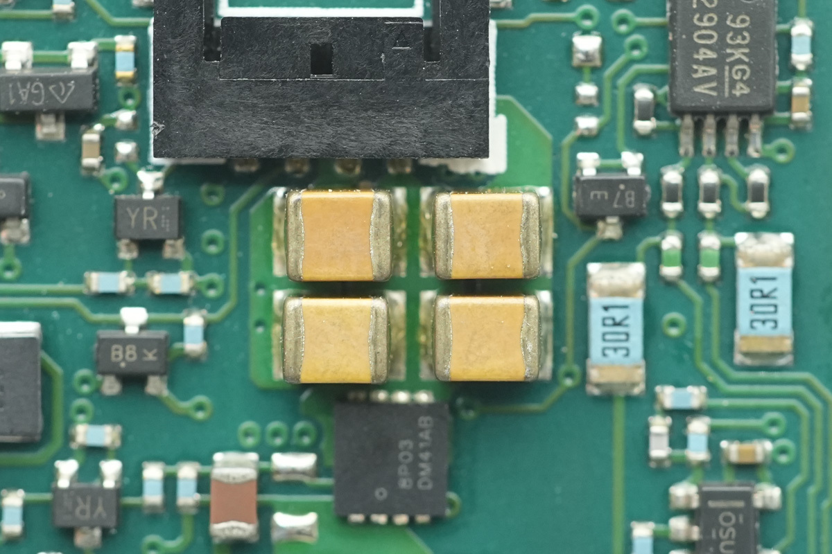
These are the filter MLCCs.
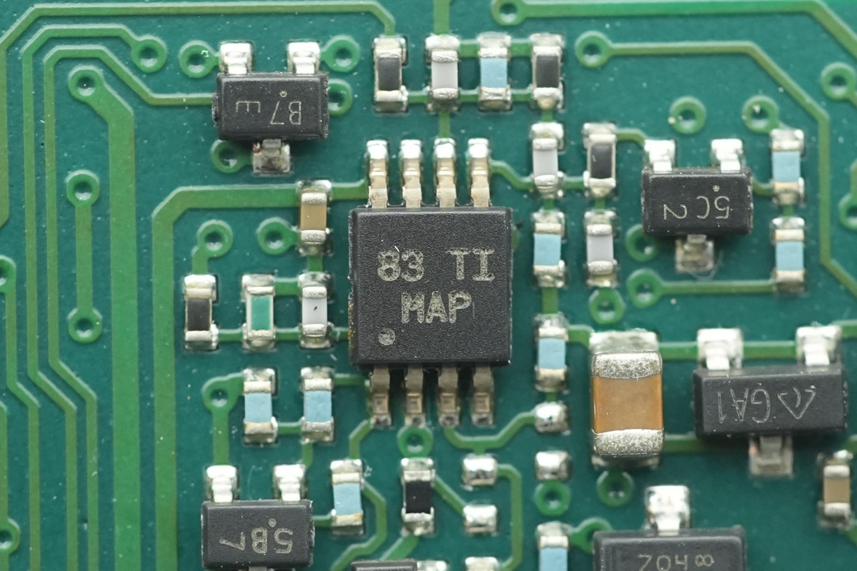
The voltage comparator is from TI, marked MAP, model LM2903. It is a general-purpose dual voltage comparator, in a VSSOP8 package.
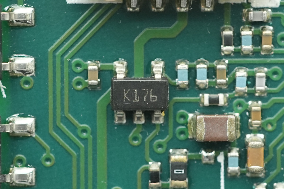
The operational amplifier is from ST, marked K176, model LMV321RILT. It is a low-power, rail-to-rail input/output single operational amplifier, in a SOT23-5 package.
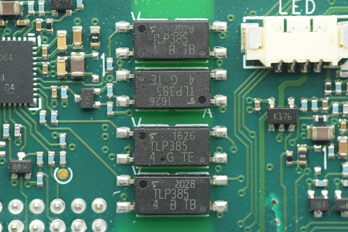
The optocoupler is from Toshiba, model TLP385, utilized for isolation in communication interfaces.
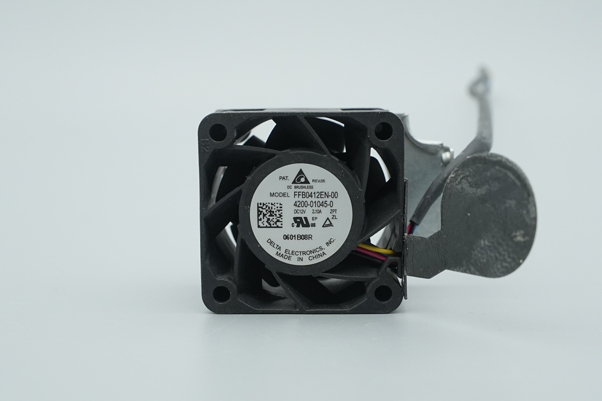
The cooling fan is from DELTA, model FFB0412EN-00, spec 12V 2.1A, and is manufactured in China.
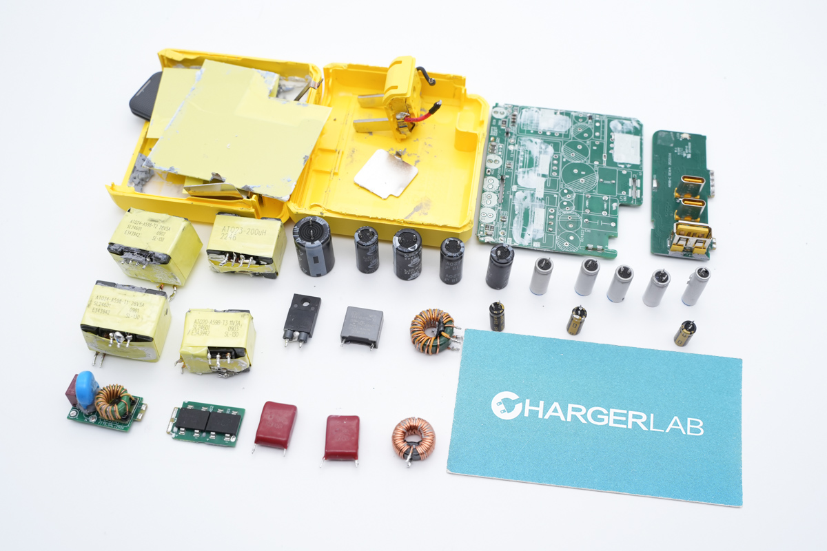
Well, those are all components of the muRata’s 2000W Titanium-Rated SiC Server PSU.
Summary of ChargerLAB
muRata’s D1U54T-W-2000-12-HC4TC is a high-performance server power supply capable of handling universal AC inputs. It outputs 12V at 166.7A for primary power and 3.3V at 3A for standby, equipped with standard cooling and connectivity hardware.
Teardown analysis shows a sophisticated design using a PFC, LLC, and synchronous rectification topology managed by TI’s UCD3138 digital controller series. The power stage is populated with high-end components, including Infineon MOSFETs and SiC diodes alongside Toshiba rectifiers.
With gate drivers from Skyworks and TI, the system demonstrates high build quality, further enhanced by Japanese capacitors and conformal coating for environmental protection.
Related Articles:
1. Teardown of Acer AC650 650W Fully Modular PC PSU
2. PowerPi MP305B DC Power Supply Set to Launch on Amazon US — Efficient Power for All Scenarios
3. MURATA US21700-VX40 Tabless Battery, 50% Charge in Just 10 Minutes!