
Introduction
We are stripping down the EcoFlow DELTA 3 1000 Air, a robust 950.4Wh portable power station powered by automotive-grade LiFePO4 cells. By leveraging an automotive-style CTC design and a unibody handle-chassis structure, EcoFlow has achieved a remarkably compact and durable build.
Performance-wise, it offers a 500W rated output, bolstered by X-Boost technology to 1000W—plenty of juice for kettles and desktops alike. Whether you're camping, managing power in a dorm, or running an outdoor live stream, it has you covered. With support for AC, solar, and car charging, you can hit a full charge in just 2.5 hours.
Equipped with a standard 5-pin AC output, plus a suite of USB-C and USB-A ports, it handles all your charging needs. Behind the scenes, an intelligent BMS handles safety, while app connectivity via Bluetooth and Wi-Fi provides total control. Let’s dive into the internals with Dianpai Energy Storage to see what makes this powerhouse tick.
Product Appearance
The EcoFlow DELTA 3 1000 Air portable power station is packaged in a corrugated cardboard box.
The box contains the portable power station unit, a user manual, and a power cable.
The unit features a cubic columnar design, with ventilation holes integrated into the side panels.
The top of the chassis features the ECOFLOW logo. The upper right side is equipped with a display screen, USB-A and USB-C ports, a power button, and voltage indicator lights. The lower right side incorporates the main power switch and an AC output socket.
The display screen provides real-time monitoring of remaining charge/discharge time, battery percentage, and both input and output power. A power switch is positioned in the center, with LED indicators below to monitor input voltage status, specifically indicating under-voltage, normal operation, and over-voltage conditions.
The power switch and AC output socket.
The opposite side is equipped with a solar charging input port and an AC charging input port.
The solar charging input utilizes an XT60 connector.
The ventilation vents are equipped with an internal cooling fan and a dust-proof mesh.
The AC charging input port.
The base features anti-slip rubber pads at all four corners, along with a product spec label.
The product label on the bottom of the portable power station:
EcoFlow DELTA 3 1000 Air Portable Power Station
Model: EF-DL3-A
Capacity: 950.4Wh (9.6V⎓99Ah)
Discharge Temperature: -10℃ to 45℃
Charge Temperature: 0℃ to 45℃
AC Input (Charging Only): 220-240V~ 50Hz/60Hz 2.5A
AC Input (Bypass Mode): 220-240V~ 50Hz/60Hz 5A
Solar Input: 12-60V⎓15A, 500W Max
Car Charging Input: 12-48V⎓8A, 384W Max
AC Output (Discharging Only): 220V~ 50Hz, 500W Max
AC Output (Bypass Mode): 220-240V~ 50/60Hz, 500W Max
USB-A Output (x1): 5V⎓2.4A, 12W Max
USB-C Output (x1): 5V⎓3A / 9V⎓2A / 12V⎓1.5A, 18W Max
Total Output: 530W Max
The AC inverter output voltage of the unit is about 220.1V.
The AC inverter output frequency is about 49.8Hz.
ChargerLAB POWER-Z KM003C shows that the USB-C port supports FCP, SCP, AFC, QC3.0/QC4+, PD3.0, PPS, DCP and Apple 2.4A.
And it also supports three fixed PDOs of 5V3A, 9V2A and 12V1.5A, and features two PPS subsets: .3-5.9V3A and 3.3-11V2A.
The USB-A port supports 5V output.
The height of the PSU is about 260mm (10.236 inches).
The width of the PSU is about 220mm (8.661 inches).
The thickness of the PSU is about 220mm (8.661 inches).
The weight is about 10kg (352.74 oz).
Teardown
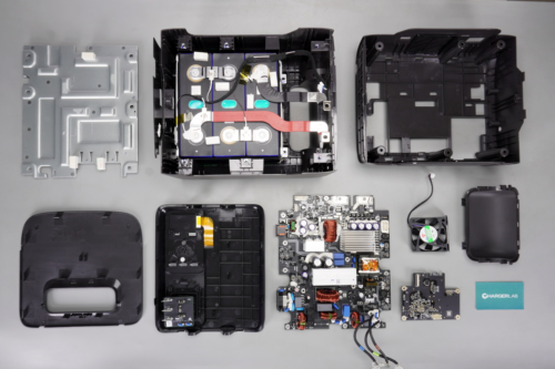
With the unboxing complete, it is time to go deeper. Let’s disassemble the EcoFlow power station to reveal the engineering and components housed within.
First, pry open the top cover of the chassis.
Fixed screws are located beneath the cover.
The base of the chassis features securing screws concealed by decorative plastic covers.
Unscrew the top and bottom securing screws and remove the front panel. The panel is connected to the main unit via wiring harnesses and connectors.
Unscrew the securing screws located beneath the panel.
Remove the front cover to reveal the bi-directional inverter module integrated within the chassis.
The bi-directional inverter module is secured by screws. On the left, the positive and negative terminals connecting to the battery pack are also fastened with screws.
A metal baseplate is installed beneath the bi-directional inverter module, featuring thermal pads to facilitate heat dissipation for the onboard components.
The cooling fan is from YINGTIAN, model YTD126015SQH, spec 12V0.3A.
Below the metal baseplate lies the battery pack, which is protected by Mylar insulation and secured with buffer pads to ensure stability and structural safety.
The battery pack is connected to the bi-directional inverter module via copper busbars, which are insulated with red and black heat-shrink tubing.
The battery pack is secured to the base with potting compound, reinforced with steel strapping on the sides, and further protected by an external metal frame.
The battery pack is configured as a 3S connection of LiFePO4 cells, with a measured voltage of approximately 9.89V.
The battery pack is equipped with two thermistors, secured by white thermal potting compound, to provide real-time temperature monitoring.
The battery voltage sensing wires are connected via spot welding.
The weight of the battery pack and chassis is about 7.35kg (259.26 oz).
Here is the bi-directional inverter module, the upper-left section houses the battery terminals, fuses, protection MOSFETs, and filtering caps. Directly below are the connectors for battery voltage and temperature sensing. The lower-left area includes the charging input port, featuring a dedicated fuse, filtering chokes, and filtering caps. A heatsink is provided for the MPPT switching MOSFETs, positioned alongside the step-down choke.
Above the step-down choke, there is another heatsink, with filtering caps on the left and a transformer on the right. Beneath the transformer are the resonant and high-voltage filter caps. The right-side heatsink manages heat for the LLC switching MOSFETs and totem-pole PFC MOSFETs. To the left of this heatsink, the circuit includes the PFC choke, X2 safety caps, common-mode chokes, and relays. The top section contains the auxiliary power transformer and switching MOSFETs.
The back of the bi-directional inverter module hosts the control and protection circuitry, including the battery protection IC, MCU, current sensing ICs, gate drivers, isolated communication ICs, power MOSFETs, and SMD Y-caps. All critical components are coated with conformal coating and potting compound for electrical insulation and environmental protection.
The positive tab of the battery is connected via welding, with positioning through-holes provided on both sides.
The SMD fuse is from VICFUSE, spec 100A 72VDC, used for battery pack overcurrent protection.
The negative connection tab of the battery is connected via welding, with positioning holes provided on both sides.
Two 0.5mΩ current sense resistors are used to detect the battery pack current.
The battery protection IC is from TI, model BQ7694202, which supports 3-series to 10-series lithium-ion and lithium iron phosphate battery applications. The chip integrates internal NMOS drivers, dual programmable LDOs, and an I2C communication interface. It also features two independent ADCs supporting simultaneous voltage and current sampling, and is packaged in a TQFP48 format.
The battery protection MOSFETs, configured in a 6-parallel connection with opposing series arrangement.
The battery protection MOSFET is from CRMICRO, model CRSM013N06N4Z, NMOS, 60V and 1.1mΩ, and packaged in a DFN5*6 package.
Copper strips are soldered at the corresponding positions to enhance current-carrying capacity.
The filtering cap is from AiSHi, belonging to the RJ series of 105℃ heat-resistant and long-life electrolytic caps.
The filtering caps, 63V470μF.
The MCU used for the low-side and LLC control of the portable power station is from GigaDevice, model GD32F303RCT6A, which is a microcontroller featuring a main frequency of up to 120MHz and an embedded Cortex-M4 core. It incorporates 256KB of Flash memory and 48KB of SRAM, supports PWM signal output, and in an LQFP64 package.
Eight switching MOSFETs are located beneath the heatsink, used for inverter step-up and synchronous rectification.
The switching MOSFETs are from CRMICRO, model HGQ024N04A, NMOS, 40V and 1.6mΩ, and in a PDFN5*6 package.
The driver is from TI, marked 27211Q, model UCC27211A-Q1. It is an automotive-grade 120V driver featuring 8V UVLO functionality, providing a 3.7A source current and a 4.5A sink current capability. It supports an 8-17V supply voltage and in an SOIC8 package.
Another one shares the same model.
Here is the XT60 DC input socket.
The SMD fuse is provided at the input end, spec 20A.
The varistor is from STE, model 5D820K, used for absorbing overvoltage surges.
The common-mode choke is wound using enameled wire.
The switching MOSFET used for power supply control is from CRMICRO, model CRSM043N10N4, NMOS, 100V and 3.8mΩ, and in a DFN5*6 package.
The filtering caps are from AiSHi.
Spec 63V470μF.
Two switching MOSFETs are secured on the heatsink.
The switching MOSFETs are from CRMICRO, model CRST024N10N4Z, NMOS, 100V and 2.1mΩ, and in a TO-220 package.
Another one shares the same model.
The driver is from TI, model LM5108, which is a 100V-rated half-bridge gate driver featuring a 2.6A sink current and a 1.6A source current output capability. The chip is equipped with interlock protection, supports enable control, and in a SON10 package.
The step-down choke is wound using enameled wire, with bakelite insulation board provided at the bottom and reinforced with white potting compound.
Copper blocks are soldered on the side of the choke to enhance current-carrying capacity.
Two 1mΩ current sense resistors are connected in parallel to detect the output current.
The voltage comparator is from TI, marked L393LV, model LM393LV, which is a low-voltage dual rail-to-rail input comparator supporting an operating voltage of 1.65-5.5V and in an SOIC8 package.
The operational amplifier is from TI, marked T062, model TLV9062, which is a dual-channel operational amplifier supporting an operating voltage of 1.8-5.5V, featuring rail-to-rail input and output, and in a VSSOP8 package.
Another one shares the same model.
The filtering cap, spec 100μF35V.
The current sense IC is from NOVOSENSE, model NSM2015-100B5F, which is an integrated current sensor supporting a working insulation voltage of 1550VDC, a current range of 100A, and a 5V supply voltage, and in a SOW16 package.
The transformer is wound using a PQ35 magnetic core, with a bakelite insulation board provided at the bottom.
The LLC MOSFETs are from CRMICRO, model CRJT190N65GCF, NMOS, 650V and 181mΩ, and in a TO220 package.
The driver is from TI, model UCC23513B, which is a single-channel isolated gate driver with optocoupler-compatible inputs. It supports a 4A source current and a 5A sink current, an output driver supply voltage of 14-33V, and an operating temperature range of -40-150°C, and in an SOIC-6 package.
Another one shares the same model.
The high-voltage filter caps are from JH, belonging to the CD261X series of long-life caps.
The caps, spec 500V 100μF, with two units connected in parallel.
Four switching MOSFETs are provided on the other side of the heatsink, used for totem-pole PFC and output modulation.
The switching MOSFETs are from CRMICRO, model CRG15T60A83L, which are IGBTs with a spec of 600V 15A, utilizing a TO-220 package.
The driver is from NOVOSENSE, model NSD1624ED, which is a high-reliability non-isolated half-bridge driver supporting both MOSFET and IGBT applications, utilizing an SOP8 package.
Another one features the same model.
Two 100μF 35V SMD electrolytic caps provide power for the drivers.
The PFC choke is wound with enameled wire, featuring bakelite board insulation at the bottom and reinforced with potting compound.
The safety X2 cap is from SRD, spec 3.3μF.
The common-mode choke is wound with enameled wire, featuring bakelite board insulation at the bottom.
The varistor is from STE, model 14D471K, used for absorbing overvoltage surges.
The current sense IC is from NOVOSENSE, model NSM2015-80B5F, supporting an 80A range and a 5V operating voltage, utilizing a SOW16 package.
The current sense IC is from NOVOSENSE, model NSM2012-30B3R, supporting an 30A range and a 3.3V operating voltage, utilizing a SOIC8 package.
The filtering cap is from CapXon, spec 47μF50V.
The relay is from HF, model HF140FF/012-2HSW, which is a miniature medium-power relay with two built-in sets of normally open contacts. It features a contact rating of 12A 250V, a coil voltage of 12V, and a plastic-sealed type enclosure.
The common-mode choke features bakelite board insulation at the bottom.
The SMD Y-cap is from TRX, model TAY2102ME, featuring compact size and light weight, making it well-suited for high-density power products such as GaN fast chargers.
Here is the info about TRX TAY2102ME.
The varistor is from STE, model 14D621K, used for absorbing overvoltage surges.
The safety X2 cap, spec 1μF.
The varistor is reinforced with white potting compound.
A fuse is provided at the input end and insulated with an outer heat-shrink tubing.
The gas discharge tube is used to absorb overvoltage surges.
The Y-cap is from TDK, with its leads fitted with ferrite beads to suppress high-frequency interference.
The Y-cap, model CS472M.
The IEC AC power socket, reinforced via soldering.
Another relay is from Churod, model A1-S-112HA2, which is a miniature power relay with one built-in set of normally open contacts. It features a contact rating of 10A 250V and a coil voltage of 12V.
The blue Y-cap is from TDK, model CS472M.
The common-mode choke is wound with enameled wire, featuring bakelite board insulation at the bottom.
The varistor provides overvoltage protection.
The blue Y-cap is from TDK, model CS472M.
The rectifier bridge is from PINGWEI, model TMBF310, spec 1000V 3A, utilizing a TMBF package.
The high-voltage filter cap is from CapXon, spec 22μF 450V.
The auxiliary power control chip is from UTC, model UC2845G, which is a high-performance current-mode controller utilizing an SOP-8 package.
The filter cap supplying power to the controller, model 220μF 35V.
Another one shares the same model.
The auxiliary power switching MOSFET is from SL, model SVS70R600FE3, 700V and 600mΩ, utilizing a TO-220F-3L package.
The auxiliary power transformer.
The optocoupler is from Everlight, model EL1019 is used for output voltage feedback.
The SMD Y-caps are from TRX, model TAY2332ME, with two units connected in series to enhance safety.
The rectifier MOSFET, model ES3G, spec 400V 3A, utilizing an SMC package.
The filter cap, spec 47μF 50V.
The MCU used for PFC and inverter modulation control in the outdoor power supply is from GigaDevice, model GD32F303RCT6A.
The 8MHz SMD clock crystal oscillator.
The memory is from GigaDevice, model GD25Q64ESIG, with a capacity of 8MB, supporting an operating voltage of 2.7-3.6V, utilizing an SOP8 package.
The voltage comparator is from TI, model LM393LV.
Another one shares the same model.
The operational amplifier is from TI, model TLV9062.
Two operational amplifiers of the same model are also located on the front of the PCB.
Another operational amplifier.
The isolation chip is from NOVOSENSE, model NSi8241C0, featuring a 5kV isolation rating, 3 forward channels and 1 reverse channel, supporting an operating temperature range of -55 to 125°C, and utilizing an SOP16 package for MCU communication between the high-voltage and low-voltage domains.
The synchronous step-up chip is from JOULWATT, model JW5513, which is a synchronous boost converter supporting an input voltage of 2.6-20V and an output voltage of up to 20V. It integrates an internal power switch, supports a switching frequency of 300kHz to 2MHz, and uses a QFN3x3-20 package.
Here is the info about JOULWATT JW5513.
The switching MOSFET is from Din-Tek, model DTQ3607, PMOS, -60V and 50mΩ, utilizing a DFN 3x3 EP package.
The gate driver is from TI, marked 7517, model UCC27517. It is a single-channel, high-speed, low-side gate driver supporting 4A source and 4A sink peak currents, operating across a 4.5V to 18V voltage range in an SOT-23 package.
The synchronous step-down chip is from RICHTEK, model RT6283B, supporting an input voltage range of 4.5-30V, an output voltage range of 0.8-24V, and an output current of 3A. It integrates internal switching transistors and utilizes an SOP-8 package.
The filtering cap is from Jianghai, spec 100μF 35V.
Another one shares the same model.
The matched 6.8μH step-down choke.
The step-down switching regulator chip is from MPS, model MP9487, supporting an input voltage of 4.5-100V and an output current of 1A. It integrates an internal high-side switching transistor and supports short-circuit protection and thermal shutdown, utilizing an SOIC-8 package.
The step-down choke, 100μH.
The filtering cap, spec 220μF35V.
The step-down chip is from CHIPOWN, model PN8054P, which is a non-isolated buck converter featuring an integrated 690V breakdown voltage switching transistor, supporting a 15V output voltage, and utilizing an SOP8 package.
The step-down choke and filtering cap.
The filtering cap, 63V220μF.
The voltage regulator chip is from SGMICRO, marked GG5TF, utilizing an SOT89 package.
Another one shares the same model.
The interior of the panel is equipped with a socket PCB and a fast-charging PCB.
The socket PCB is connected via soldering and features two blue Y-caps.
The blue Y-caps are from TDK, model CS102M.
Unscrew the fixing screws to remove the fast-charging PCB.
The front of the PCB is equipped with a multiplexer chip, a wireless communication module, a synchronous step-down chip, a step-down choke, and filter caps, as well as a push-button switch and LED indicators.
The back of the PCB is equipped with a protocol chip, a synchronous buck-boost chip, an operational amplifier, and a display driver IC, along with a connection socket.
The filtering cap is from Jianghai, spec 100μF 25V.
The SMD fuse.
The synchronous buck-boost chip is from TI, marked S52892, model TPS552892, supporting an input voltage of 3-36V and an output voltage of 0.8-22V. It integrates synchronous buck-boost switching MOSFETs internally, utilizes average current mode control, supports a switching frequency of 200kHz-2.2MHz, features comprehensive protection functions, and adopts a VQFN-HR21 package.
The 5.6μH alloy power choke.
The protocol chip is from Hynetek, model HUSB380, featuring high integration, high performance, and a compact size. It supports USB PD3.1, provides 5 FPDOs and 2 APDOs, and allows configuration of 8 additional power levels via the PS0 and PS1 pins. The chip integrates low on-resistance N-MOS transistors internally, along with OVP, UVP, UVLO, OCP, fast OCP, and thermal shutdown. It utilizes a QFN4x4-32L package and is suitable for charger and car charger applications.
Here is the info about the Hynetek HUSB380.
The synchronous step-down chip is from TI, marked 933F, model TPS62933F, which is a synchronous buck converter supporting an input voltage of up to 30V and an output current of 3A. It integrates internal switching transistors, operates in forced CCM, supports an output voltage of up to 22V, and utilizes an SOT583 package.
The 6.8μH alloy power choke.
The 20mΩ current sense resistor is used to monitor the output current.
The operational amplifier is from 3PEAK, model TP2412, which is a low-noise CMOS rail-to-rail input/output dual operational amplifier utilized for current sensing and amplification, adopting an MSOP8 package.
The auto-identification chip for the USB-A port is from Injoinic, marked A12K, model IP2112. It is a dual-port USB charging protocol IC supporting Apple, Samsung, and BC1.2 charging protocols, with an operating supply voltage range of 3-5.5V, utilizing an SOT23-6 package.
Here is the info about the Injoinic IP2112.
The USB-A and USB-C receptacles are both secured via through-hole soldering.
The synchronous step-down chip is from TI, marked 1J7, model TPS62A01, which is a synchronous buck converter supporting an input voltage of 2.5-5.5V and an output current of 1A, utilizing an SOT-563 package.
The multiplexer chip is from TI, marked TM1208, model TMUX1208, which is a bidirectional 8:1 single-channel multiplexer supporting an operating temperature range of -40~125°C, utilizing a TSSOP16 package.
The display driver IC is from i-CORE, model CS1621, supporting 32-segment by 4-common LCD drive and control, adopting an LQFP48 package.
The wireless communication module is from ESPRESSIF, model ESP32-C6-MINI-1. The module integrates an ESP32-C6 series chip featuring a 32-bit RISC-V single-core processor, an onboard PCB antenna, and support for Wi-Fi 6 and BLE connectivity.
The power switch and LED indicators.
The LED indicators are used for input voltage indication.
LED indicators are provided on both sides of the AC output switch.
Well, those are all components of the ECOFLOW DELTA 3 1000 Air Portable Power Station EF-DL3-A.
Summary of ChargerLAB
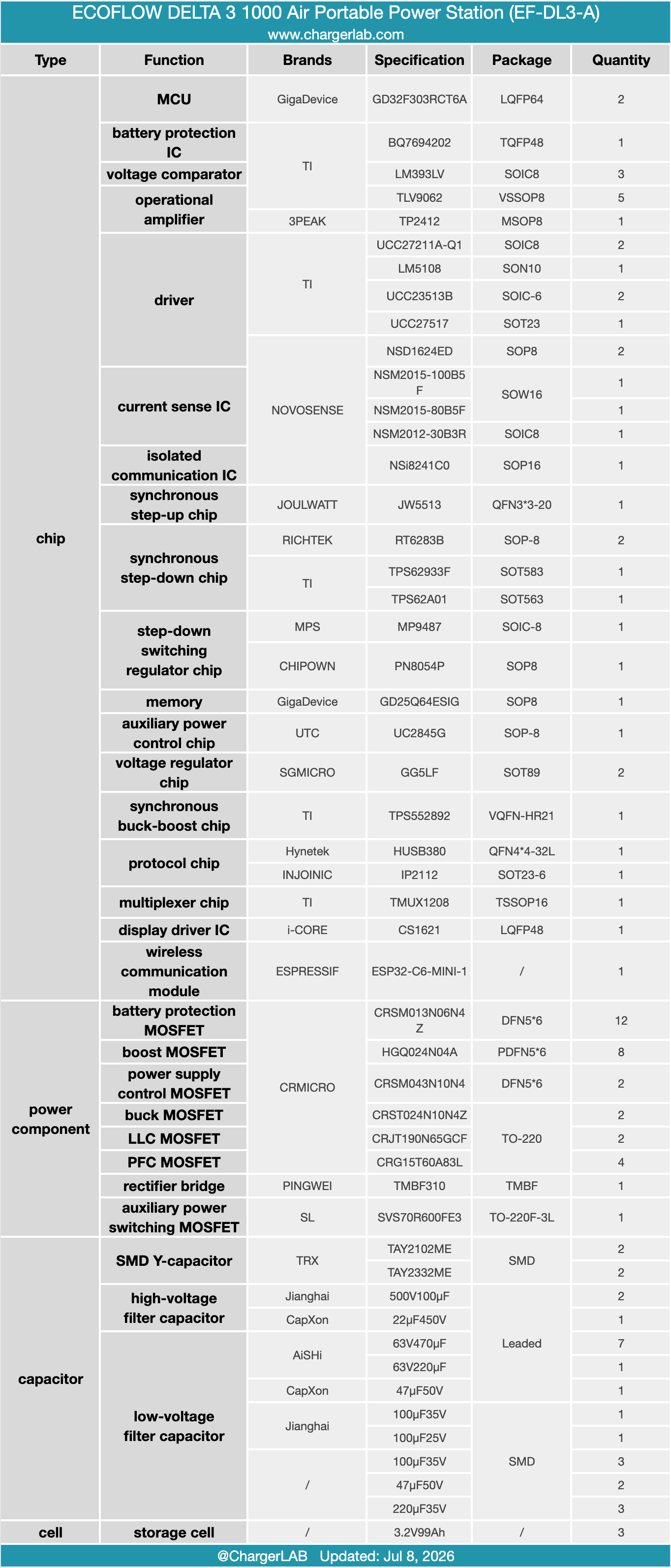
EcoFlow's DELTA 3 1000 Air portable power station packs automotive-grade LiFePO4 chemistry with an automotive CTC architecture into a remarkably compact frame. Delivering 500W of nominal output that scales up to 1000W via X-Boost technology, it accepts multiple charging inputs including solar, car, and AC mains. The front fascia hosts an informative display and output outlets, while the sides accommodate AC/DC charging ports and an active cooling fan.
Our teardown reveals an internal 3-series prismatic LiFePO4 battery pack anchored to the chassis via adhesive and fasteners. Flanked by protective metal plates and secured with steel binding strips, the assembly uses an integrated thermistor for thermal management and heavy-duty copper ribbons to link with the bidirectional inverter module.
Mounted atop the battery enclosure is a multi-function PCBA integrating the bidirectional inverter, MPPT step-down stage, and battery management system. Core processing relies on a pair of GigaDevice GD32F303RCT6A MCUs for system and inverter control, paired with a TI BQ7694202 protection IC.
Power components including protection MOSFETs, boost MOSFETs, LLC MOSFETs, and modulation IGBTs originate from CRMICRO, driven by NOVOSENSE and TI gate drivers. NOVOSENSE also provides the current sensing and isolated communication ICs. USB-C power delivery utilizes a TI TPS552982 buck-boost converter and a Hynetek HUSB380 protocol controller. Finished with conformal coating and underfill adhesive reinforcement, the entire PCBA is built to withstand rigorous outdoor environments with maximum reliability.
Related Articles:
1. Teardown of the Delta 3000W SiC Server PSU (DPS-3000AB-22A)
2. Review of Delta's World's First PD3.1 240W USB-C Power Adapter
3.Up to 6 kWh | Introducing the EcoFlow DELTA 2 Max Extra Battery Kit