Introduction
In this teardown, we crack open Delta’s latest 3000W SiC server power supply (Model: DPS-3000AB-22A). Designed to meet rigorous data center demands, this unit supports 100–127V and 200–240V AC inputs, pumping out a massive 12V at 250A (3000W total power), alongside a 5V/3A standby rail.
Featuring a slim, rack-optimized chassis, the unit integrates a rear AC socket, LED indicators, and extraction handles, with a dedicated output connector on the front. Under the hood, it deploys a high-efficiency topology combining a bidirectional switch PFC, full-bridge LLC, and synchronous rectification, bolstered by premium silicon carbide diodes. Let’s dive into the internal architecture and premium hardware choices with the experts at ChargerLAB.
Product Appearance
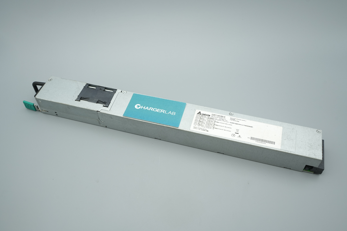
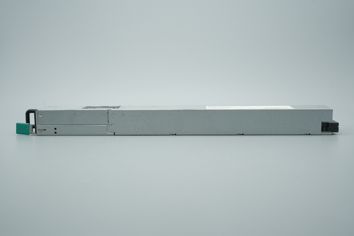
Encased in a rugged galvanized steel housing, the Delta 3000W SiC server power supply boasts a streamlined, elongated profile with an identification label clearly displayed on the front.
The chassis is hollowed out where the cooling fan is located, effectively reducing the overall thickness.
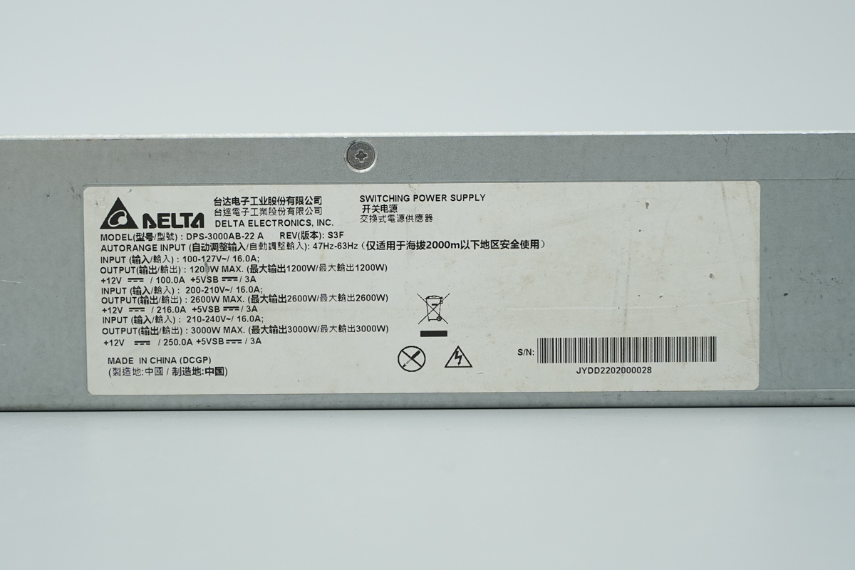
Power Supply Spec Label
Model: DPS-3000AB-22A
Input (100-127V~): 16A; Output: 1200W MAX (+12V⎓ / 100A, +5VSB⎓ / 3A)
Input (200-210V~): 16A; Output: 2600W MAX (+12V⎓ / 216A, +5VSB⎓ / 3A)
Input (210-240V~): 16A; Output: 3000W MAX (+12V⎓ / 250A, +5VSB⎓ / 3A)
The chassis is secured by screws.
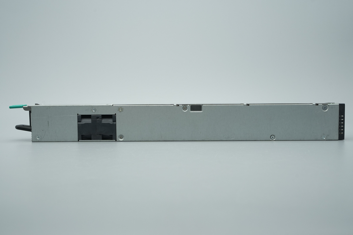
The back of the chassis is secured with screws.
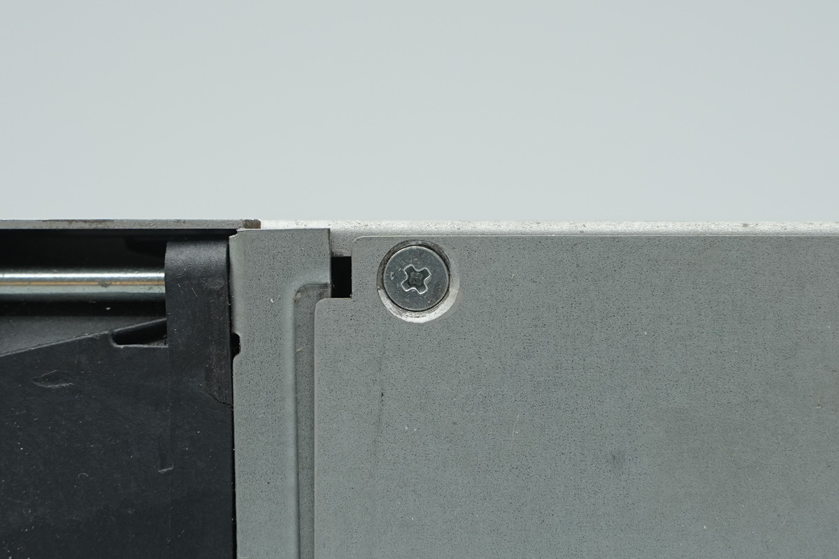
Securing screws are also provided on the side of the chassis.
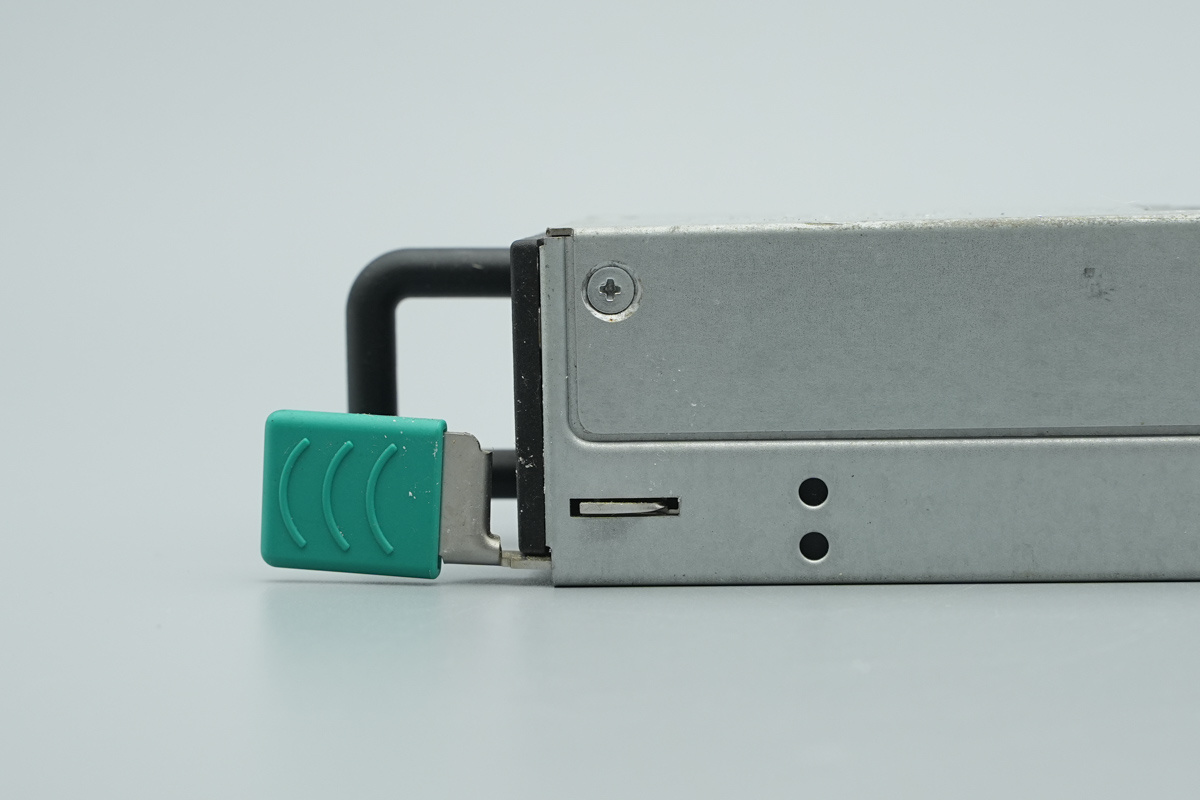
The release handle is connected to the locking latch.
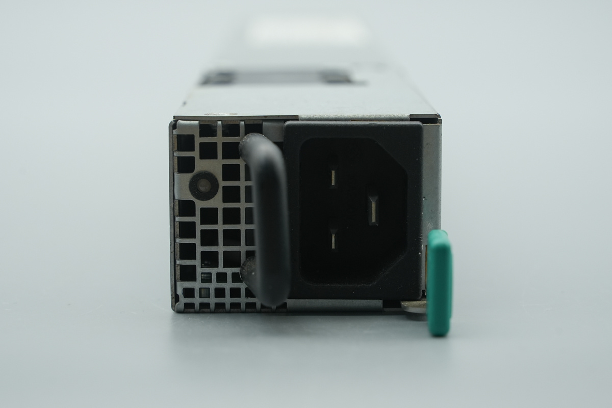
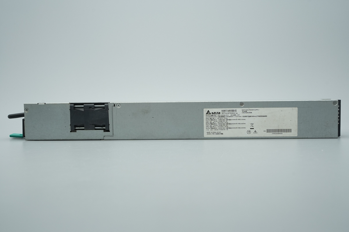
The input end is equipped with a C20 socket, LED indicators, mounting handle, and release latch.
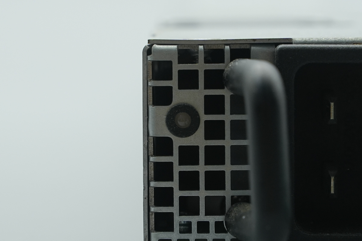
This is the LED indicators.

The output end features a dedicated connector.
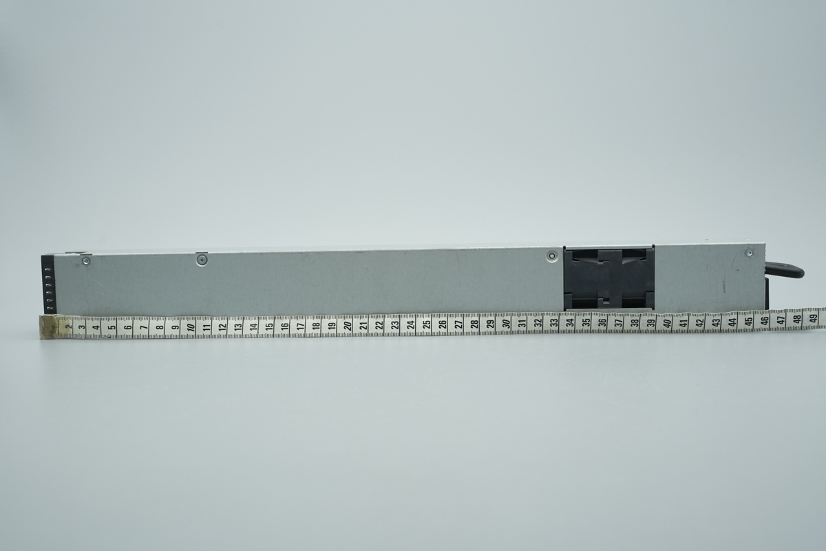
The length of the unit is about 450mm (17.717 inches).

The width of the unit is about 54.9mm (2.161 inches).
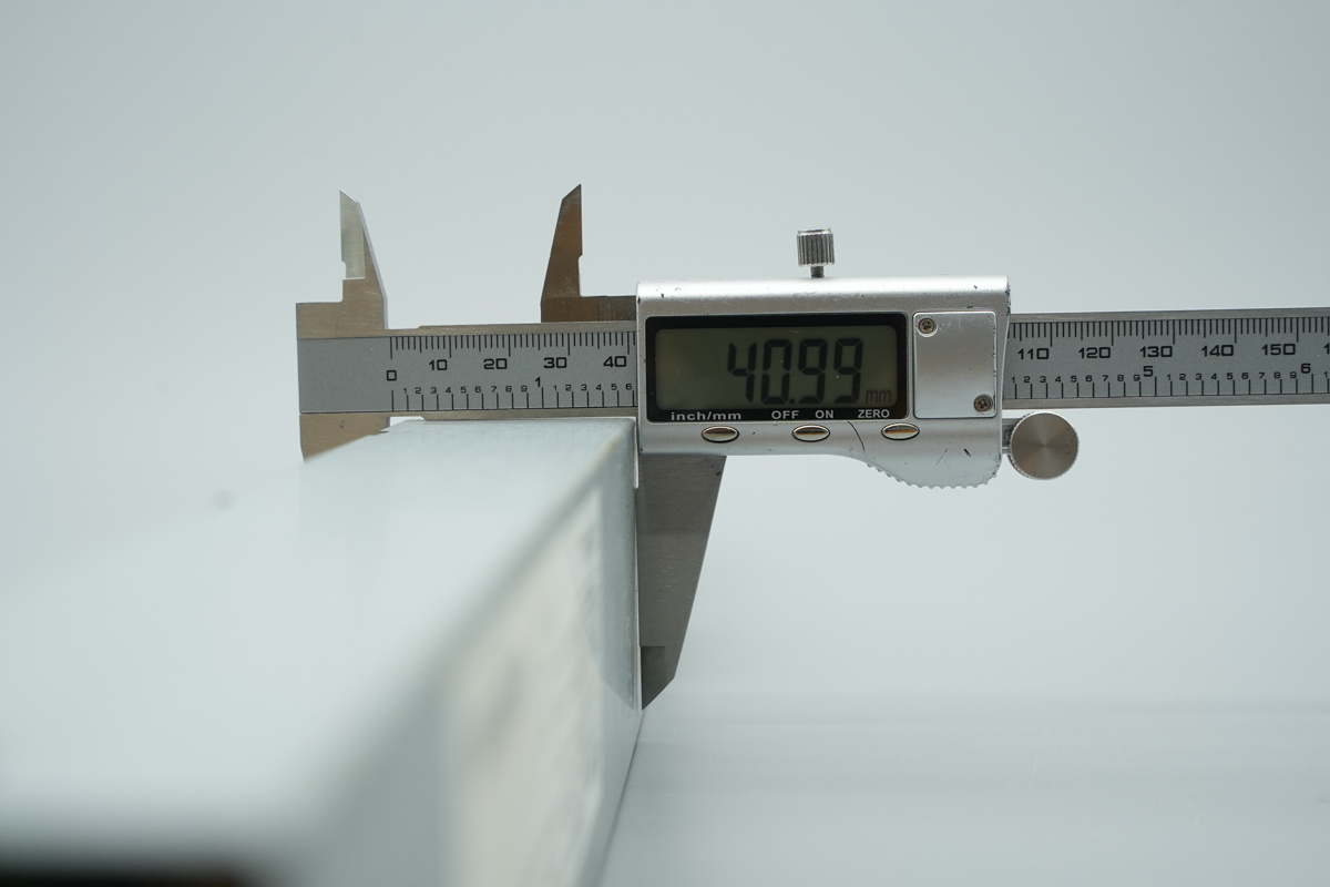
The thickness of the unit is about 41mm (1.614 inches).
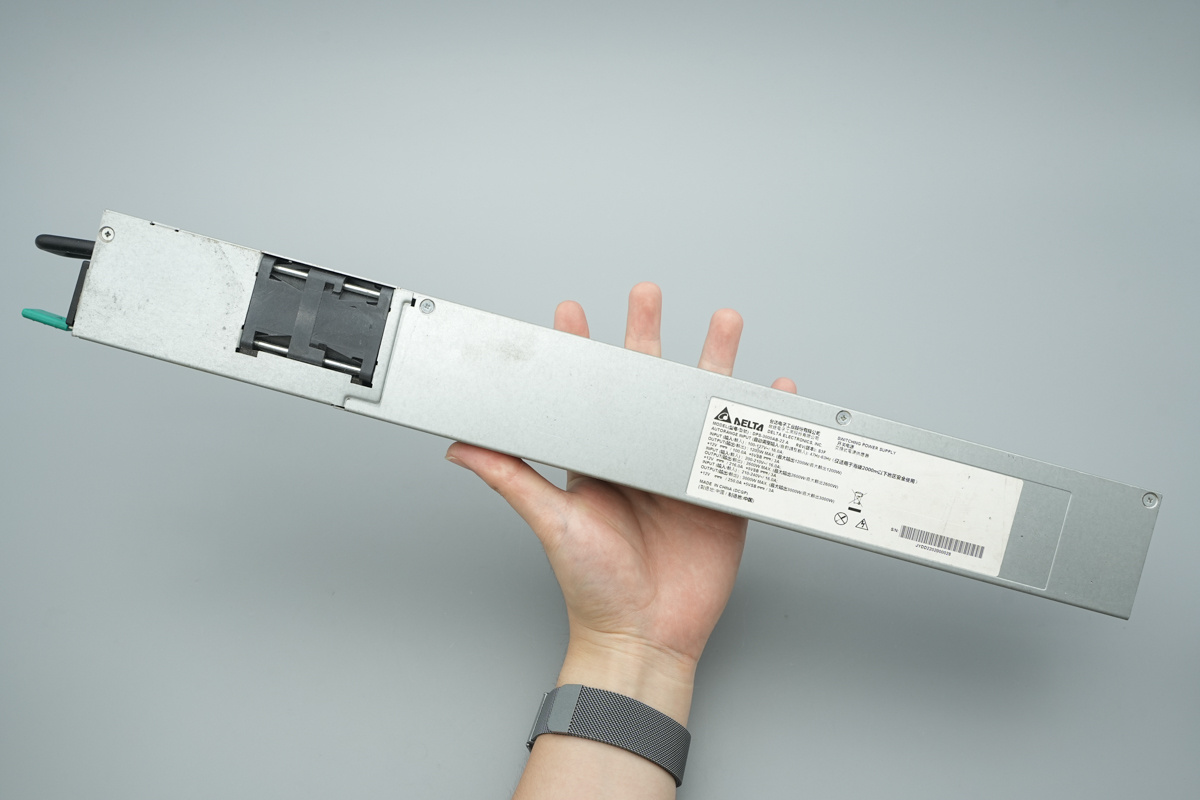
That's how big it is in the hand.
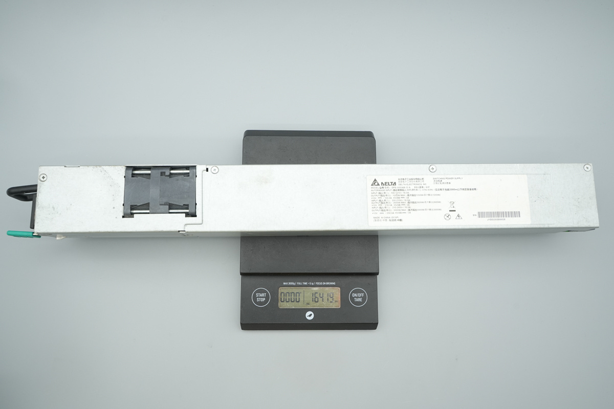
The weight is about 1642g (57.92 oz).
Teardown
With the external inspection complete, it’s time to head under the hood. Join us as we dismantle this Delta unit to reveal the engineering, internal power stages, and premium components that make it tick.
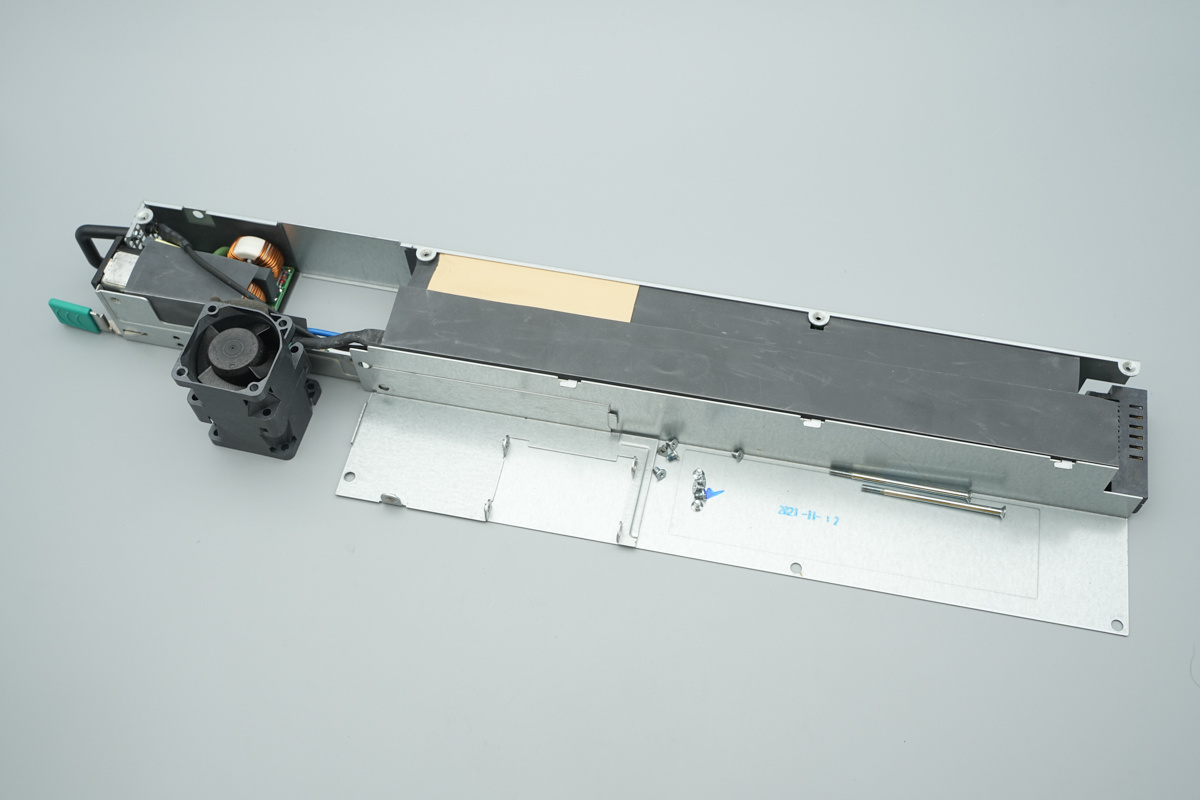
First, unscrew the retaining screws and disassemble the power supply enclosure.
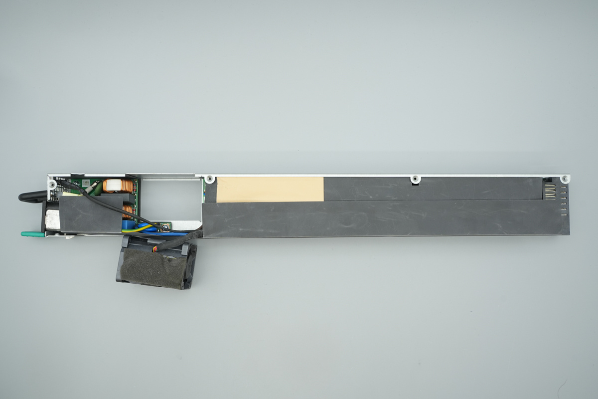
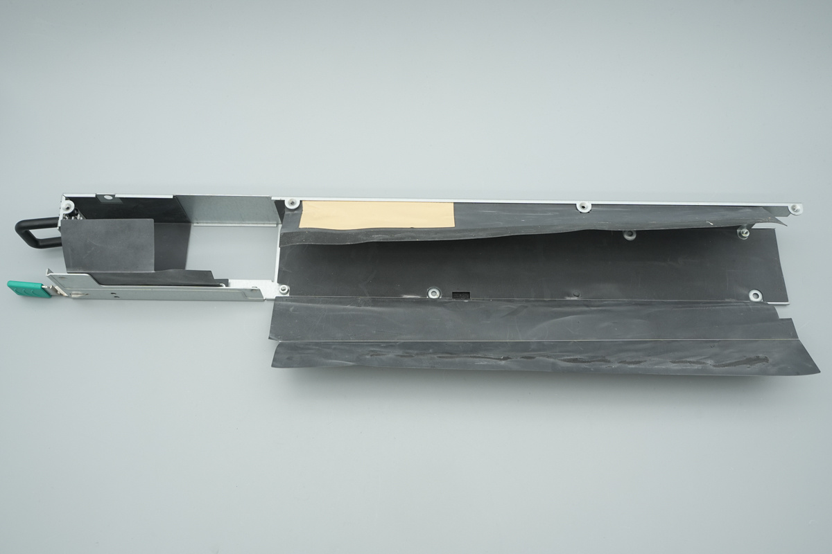
The PCBA is wrapped in Mylar film for insulation, while thermal pads are applied to correspond with internal components, facilitating enhanced heat dissipation through the enclosure.
A PCB is positioned at the input end and secured with screws.
The PCBA is also secured in place with screws.
The AC power socket at the input end is connected via soldered wires.
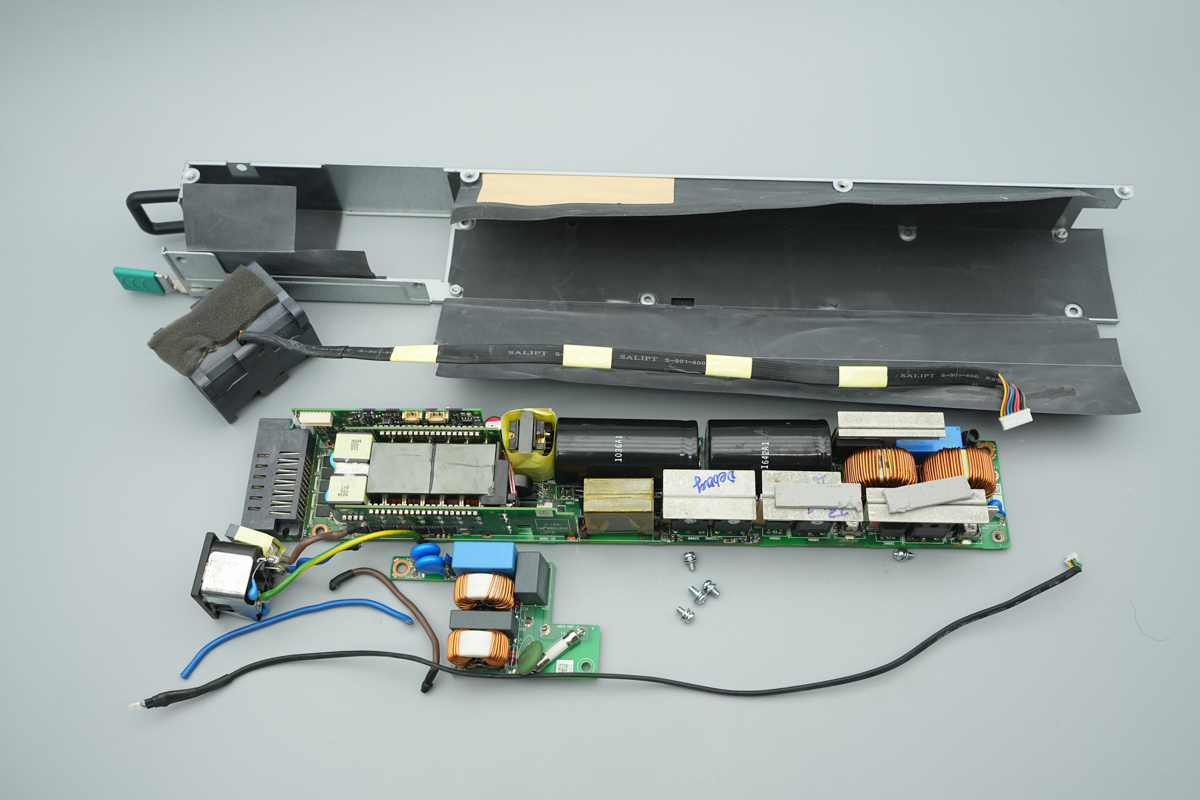
Unscrew the retaining screws and extract the PCBA module from the chassis.
The back of the PCBA is also insulated with a Mylar film.
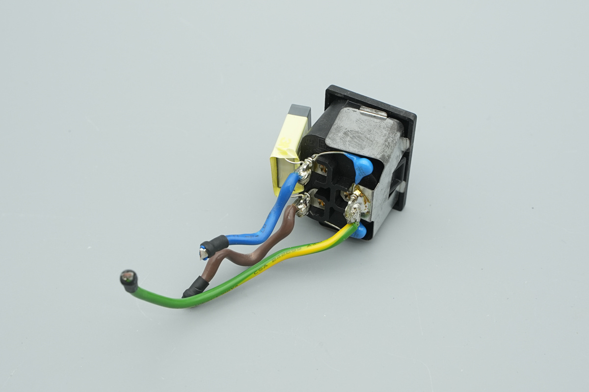
The X2 and Y caps are soldered directly to the AC power socket pins.
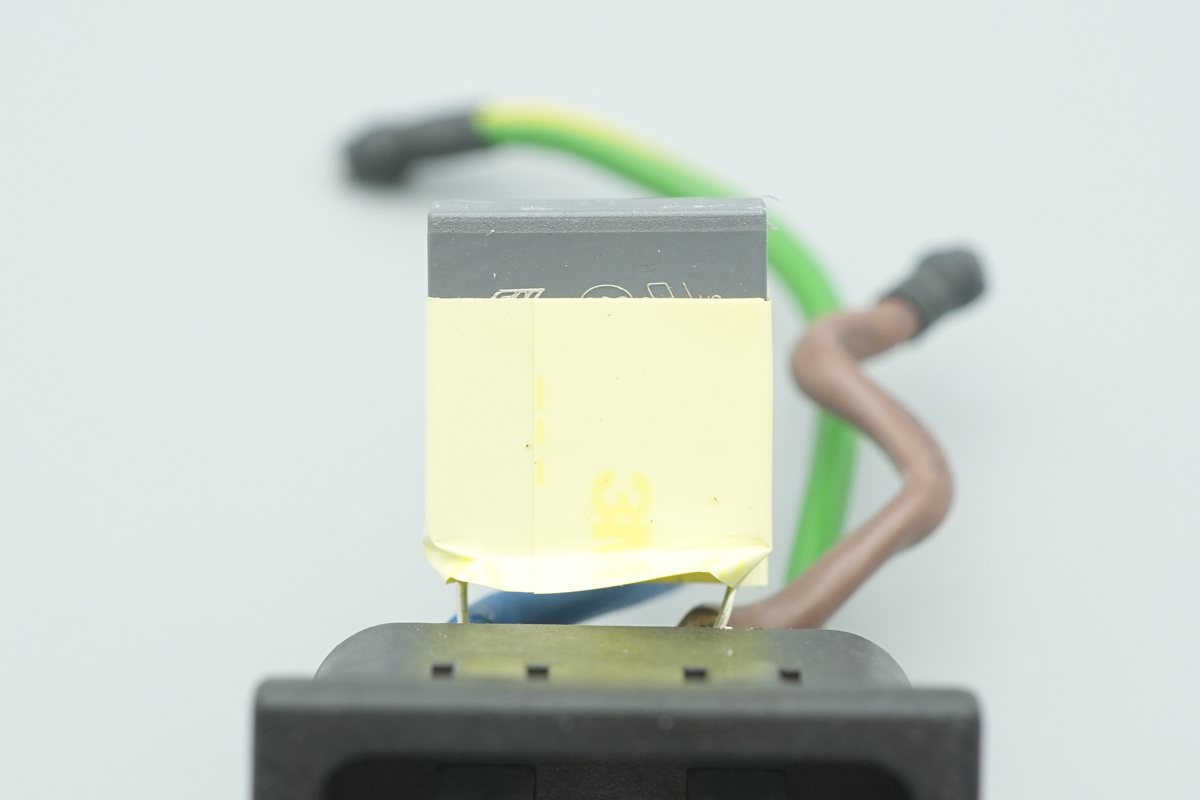
The safety X2 cap is wrapped with insulating tape.
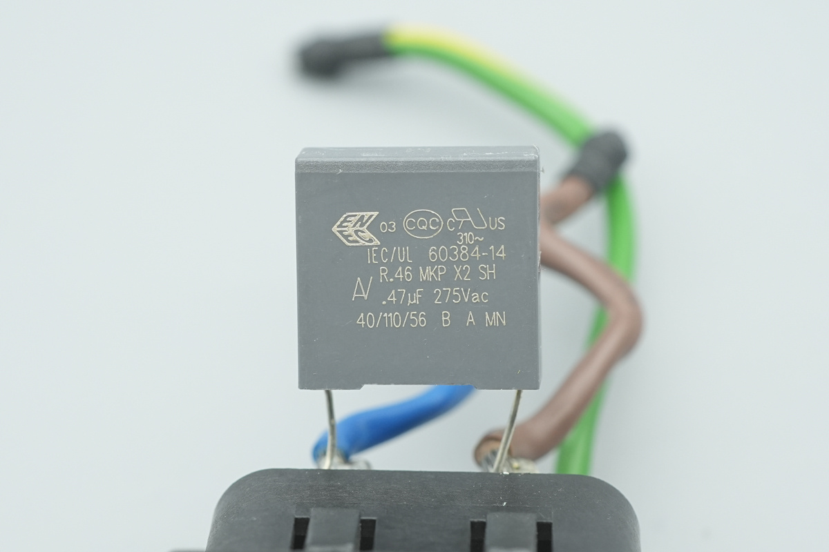
The safety X2 cap, 0.47μF.
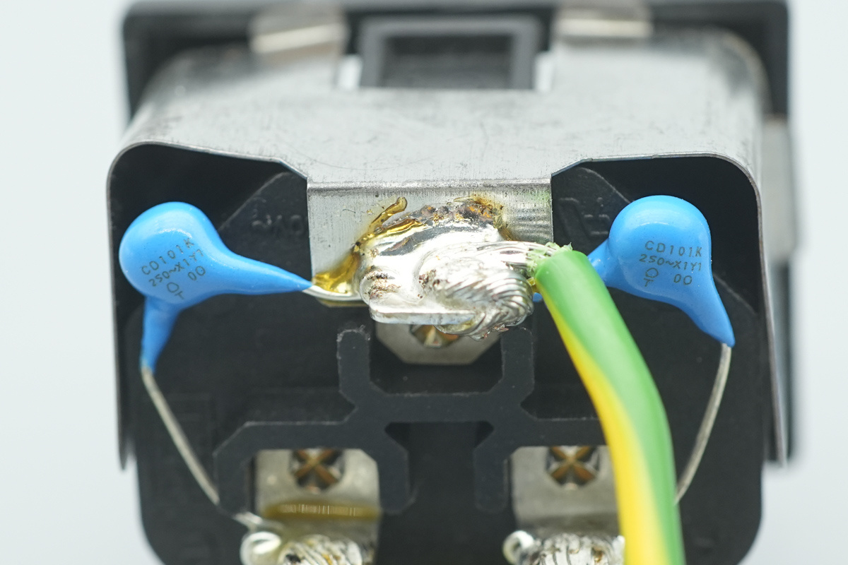
The blue Y-cap is from TDK, model CD101K.
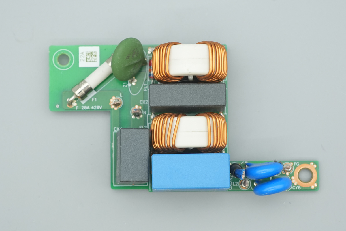
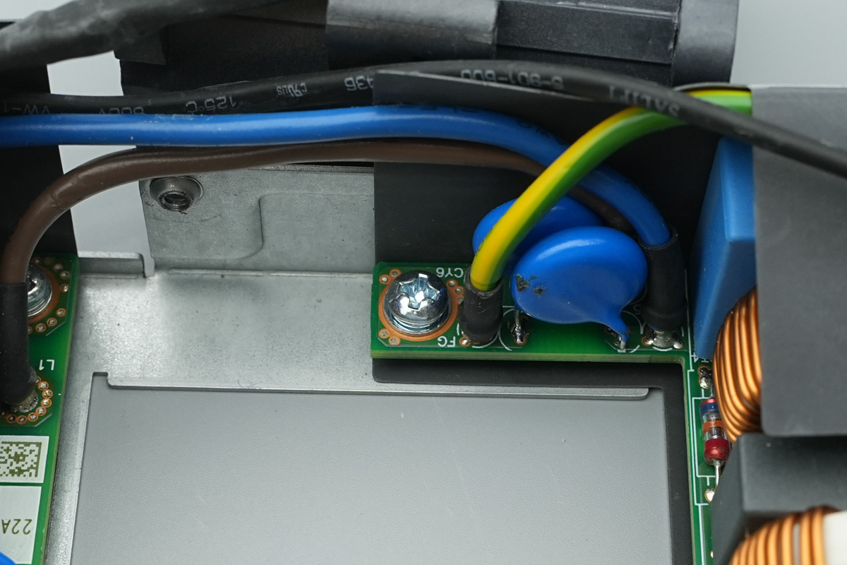
The PCB is soldered with a fuse, a varistor, a safety X2 cap, and the common-mode chokes.
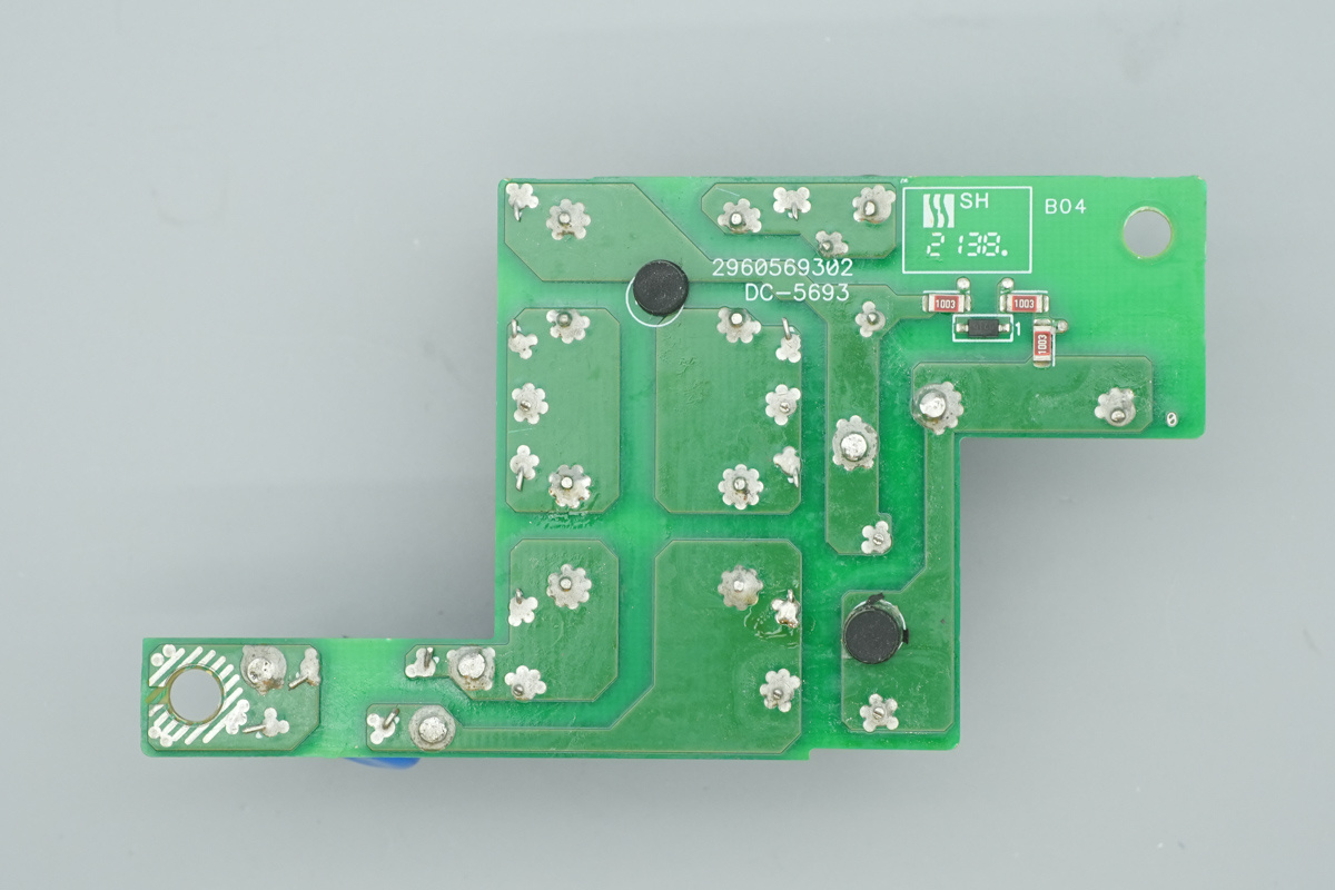
An X-capacitor discharge IC is soldered on the back of the PCB.
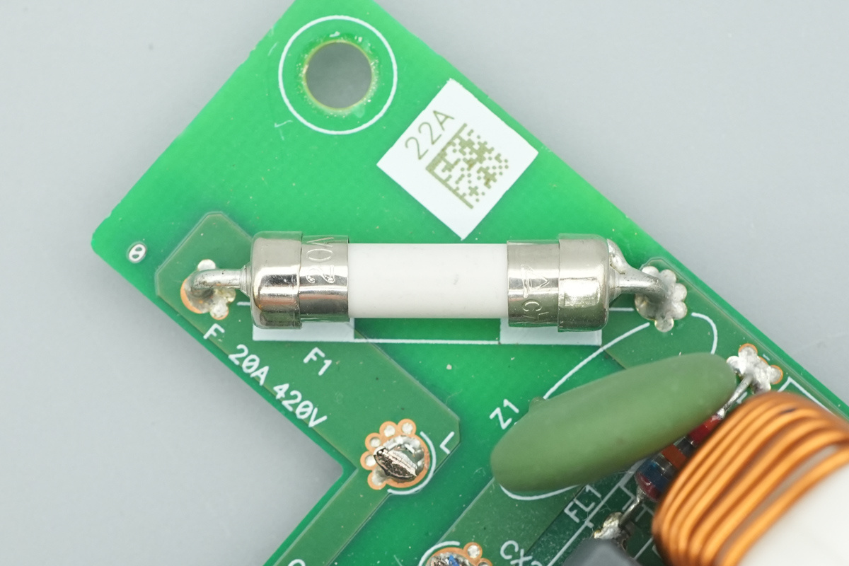
The fuse, spec 20A 420V.
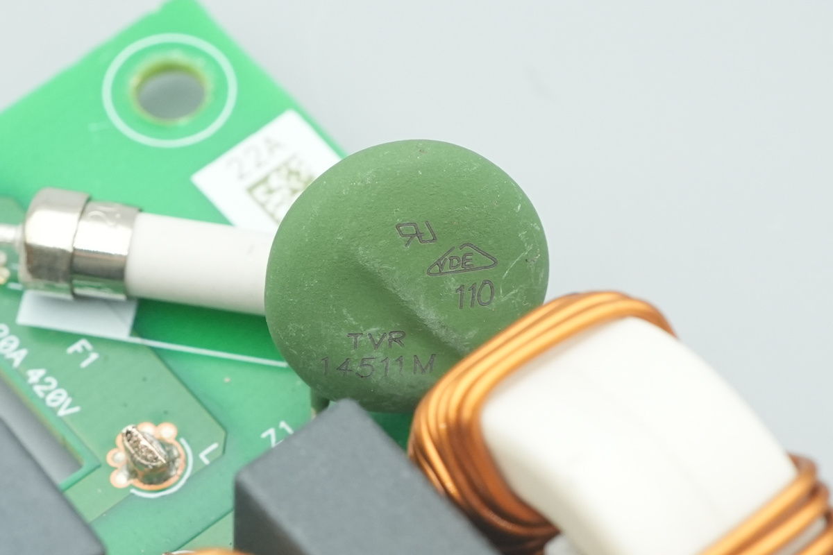
The varistor, model TVR14511M.
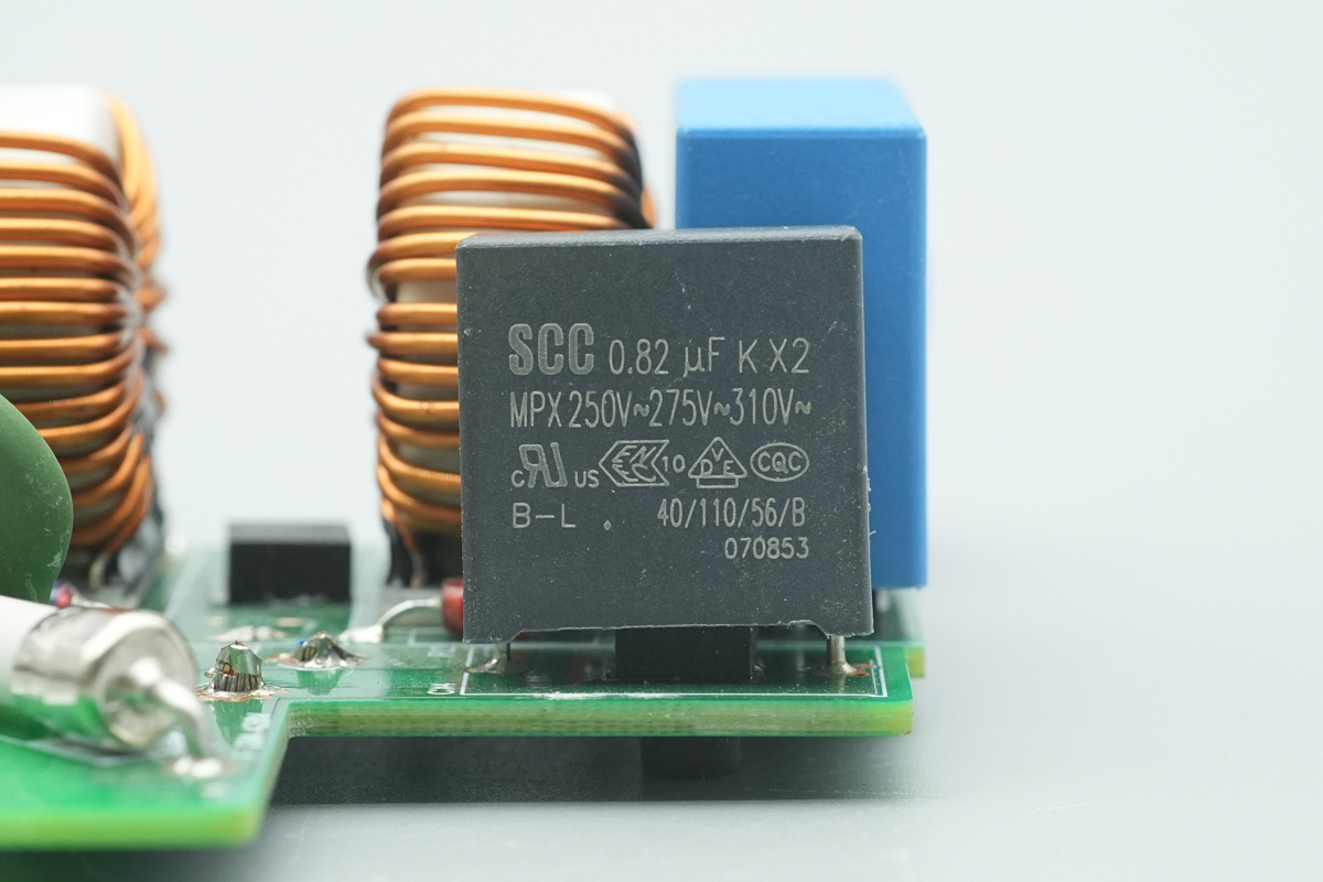
The safety X2 cap is from SCC, 0.82μF.
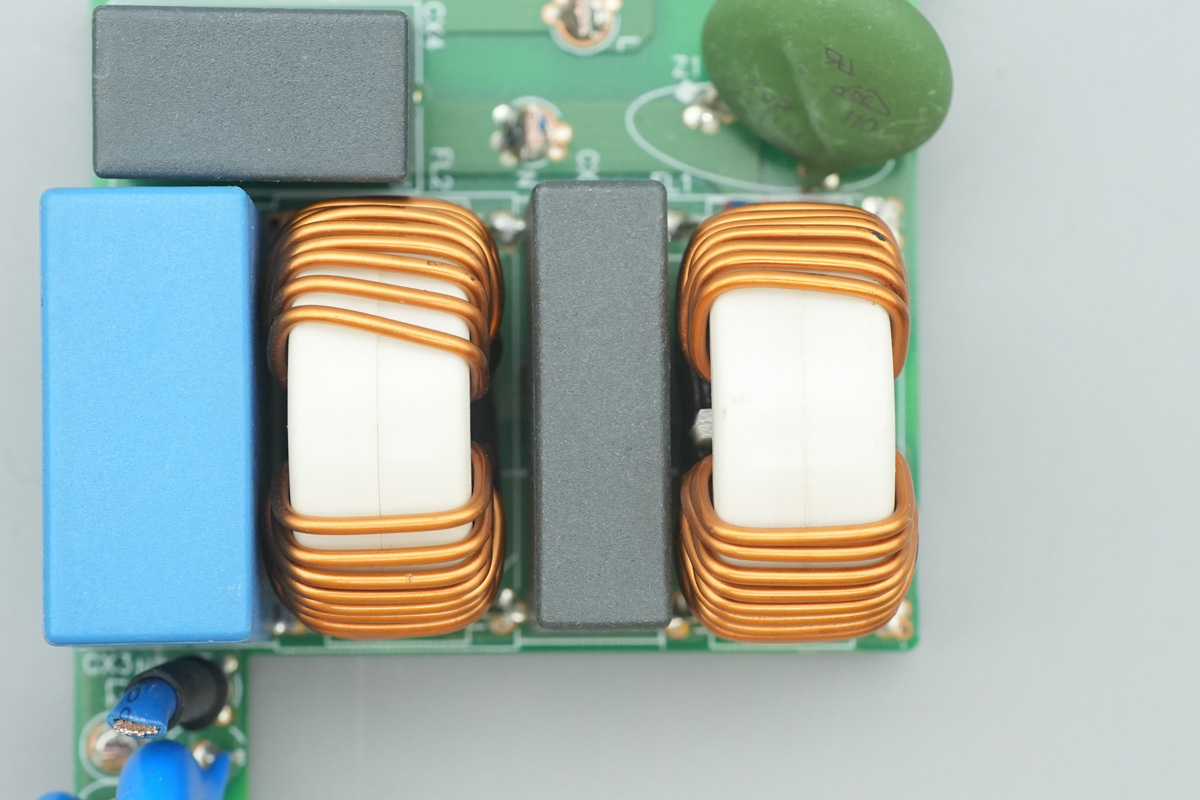
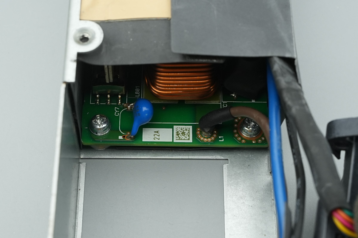
The common-mode chokes are wound with enameled copper wire.
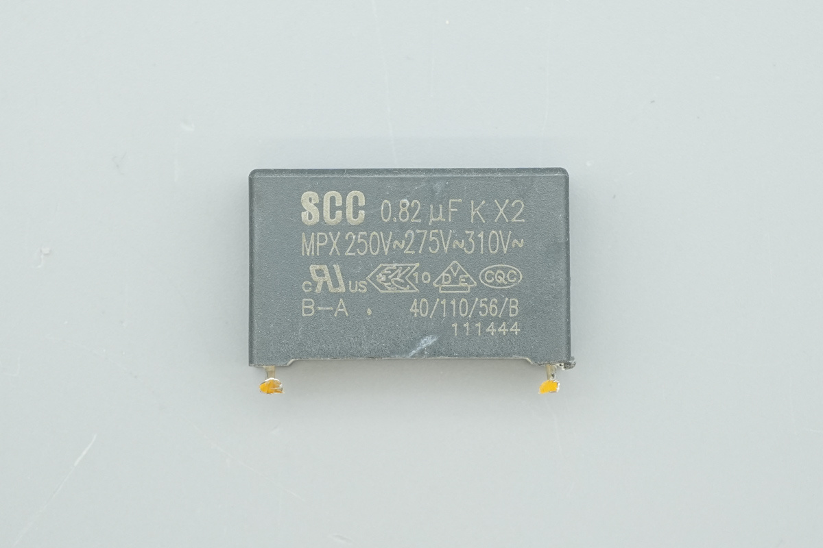
The safety X2 cap, 0.82μF.
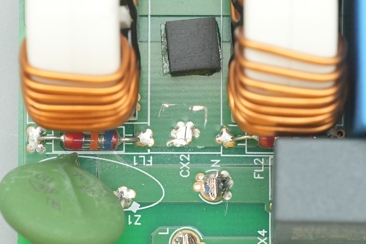
The glass gas discharge tubes are positioned on the side of the common-mode choke.
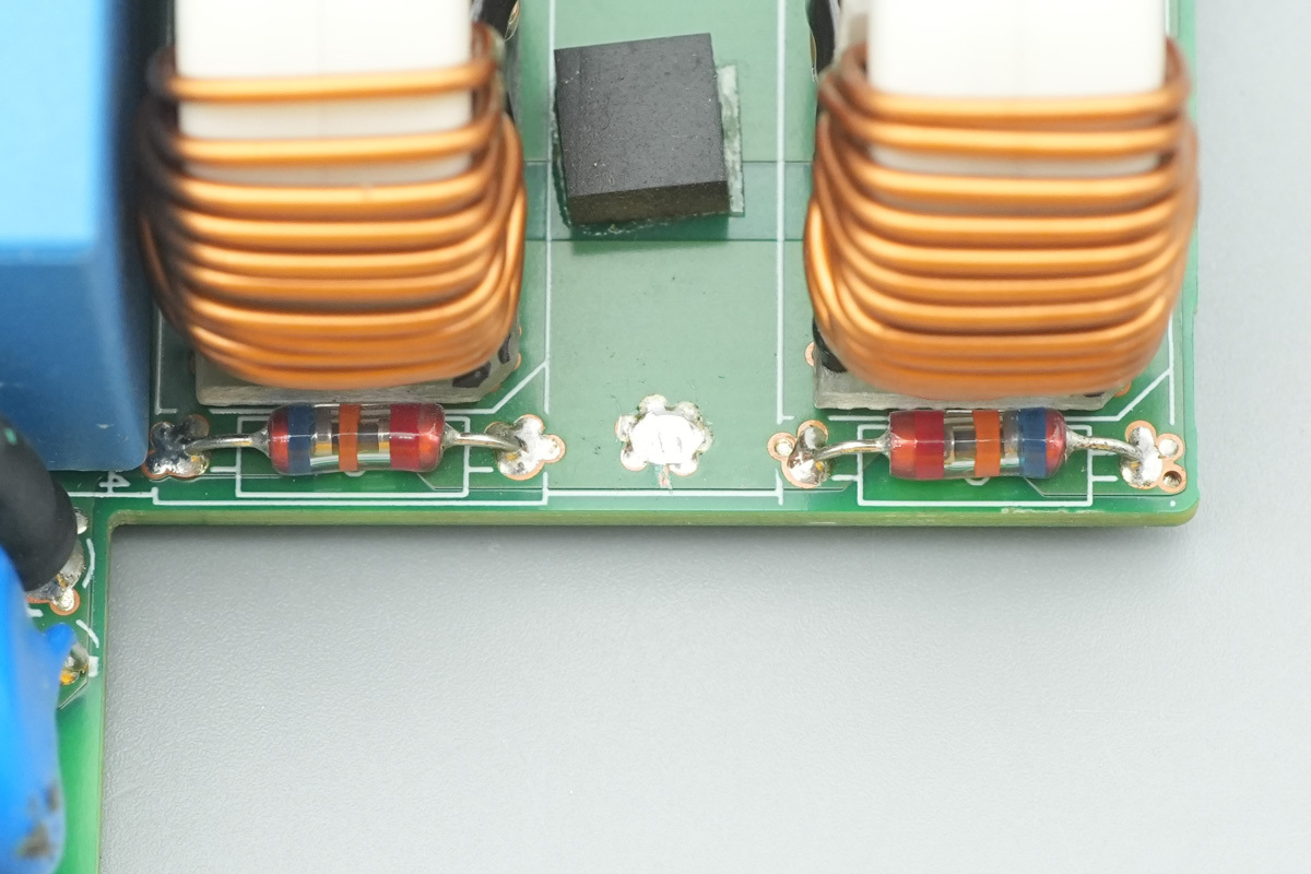
They are also provided on the other side.
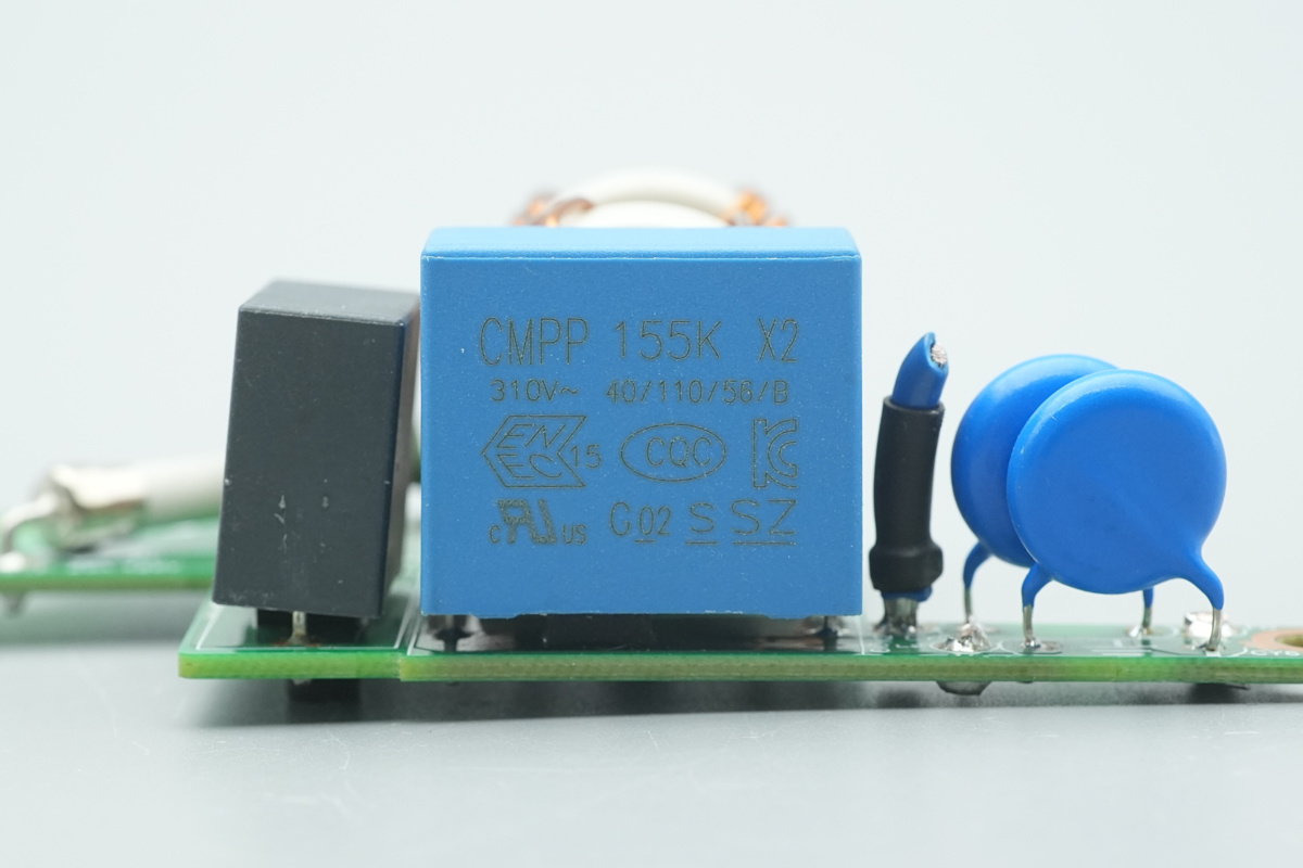
The safety X2 cap is from Sungho, 1.5μF.
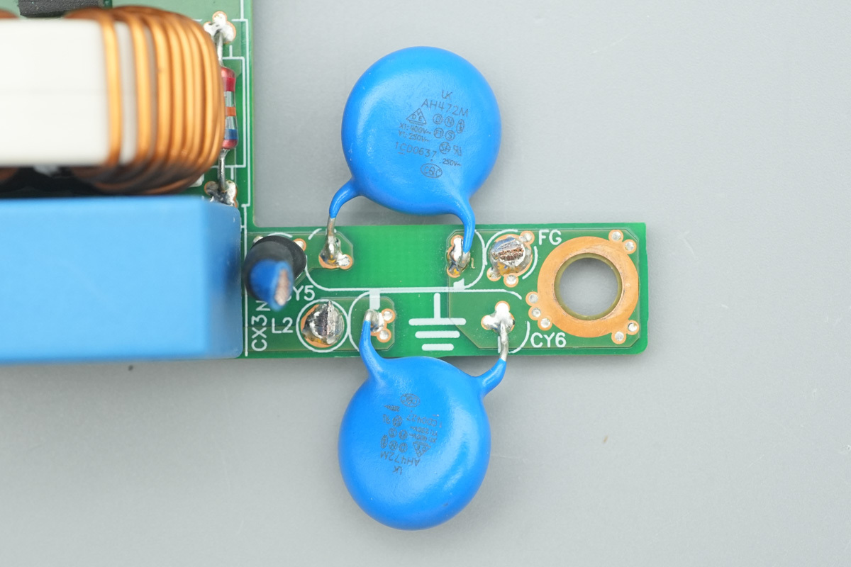
The blue Y-cap is from WTC, model AH472M.
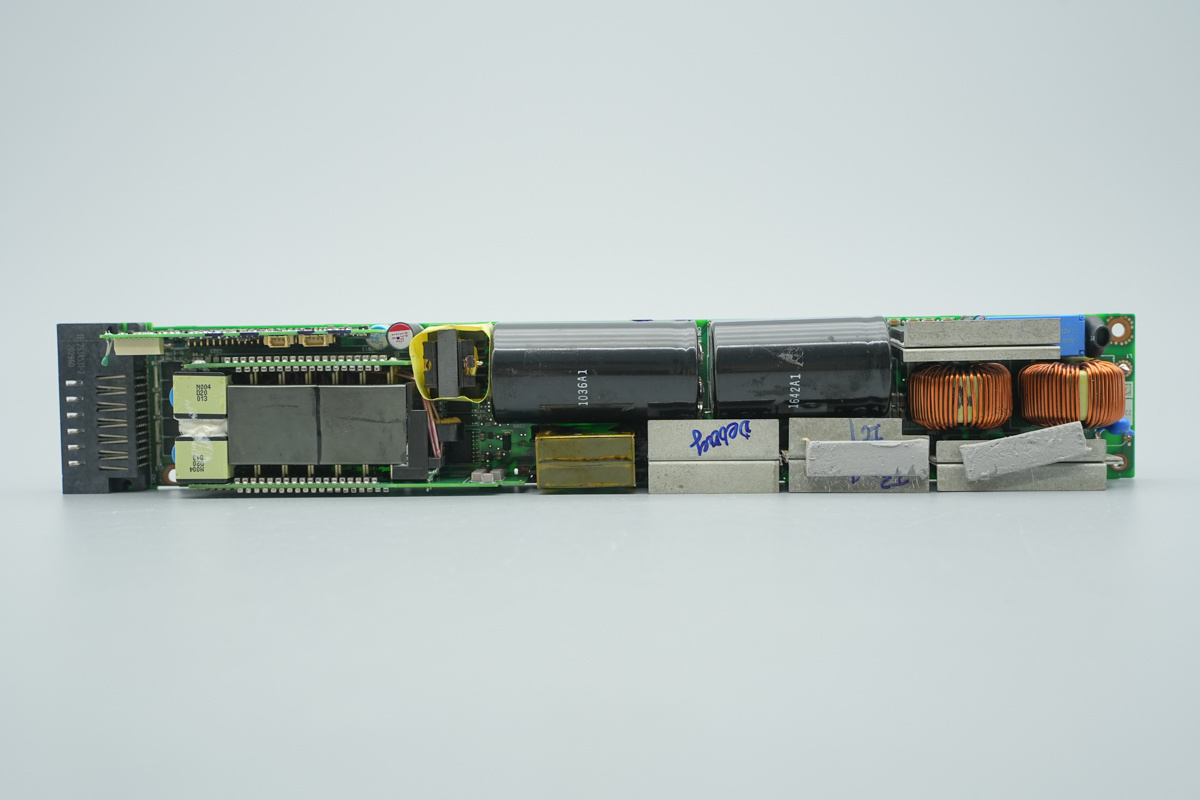
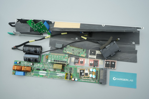
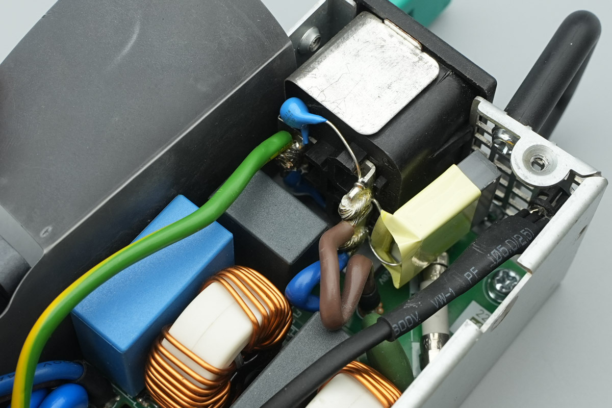
On the front right side of the PCBA is the AC input end, which is equipped with a startup resistor, a relay, and a rectifier bridge. Below it sits the PFC boost choke, with a heatsink installed at the bottom to dissipate heat for the PFC switching MOSFETs and PFC rectifier MOSFET. The central area houses the high-voltage filter caps, accompanied by the resonant choke and the heatsink for the LLC switching MOSFETs underneath.
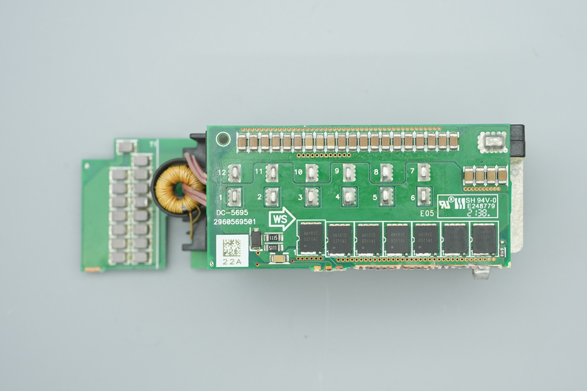
The left side features the output connector, with an auxiliary control PCB positioned above and the main transformer below. To the right of the PCB is the standby power transformer. The LLC transformer is flanked by synchronous rectifier PCBs soldered on its top and bottom, with filtering chokes and filtering caps arranged on the left.
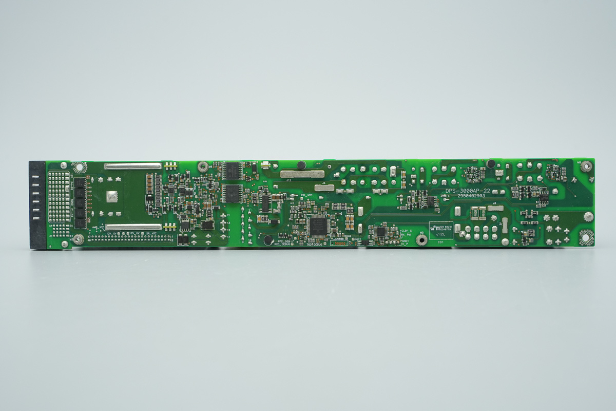
The back of the PCBA is populated with output control MOSFETs, drivers, isolated driver ICs, isolated communication ICs, a standby power IC, a PFC controller, gate drivers for the switching MOSFETs, and dedicated sampling chips.
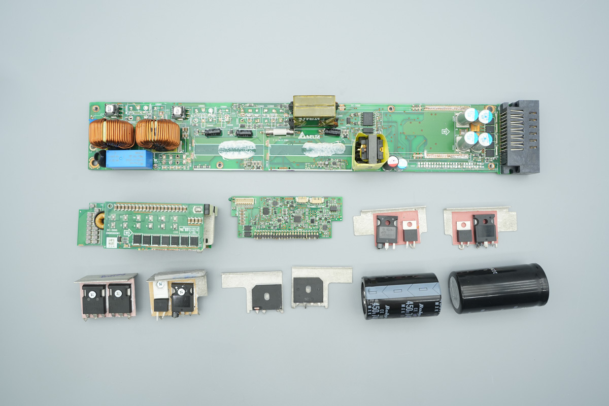
Desolder and remove the rectifier bridge, PFC switching MOSFETs, LLC switching MOSFETs, high-voltage filter caps, transformer PCBs and control PCBs to proceed with the further teardown process.
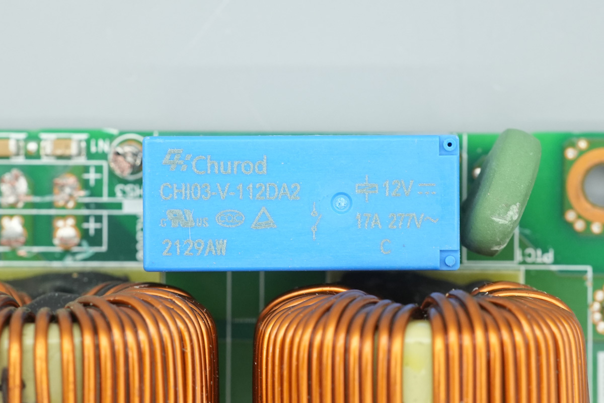
The relay is from CHUROD, model CHI03-V-112DA2. It is a miniature power relay featuring a single normally open contact set, with a contact rating of 17A at 277V AC and a coil voltage of 12V.
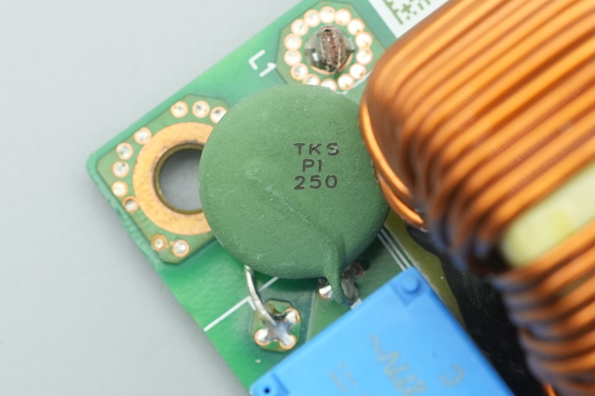
The startup resistor is from THINKING, marked TKS PI 250.
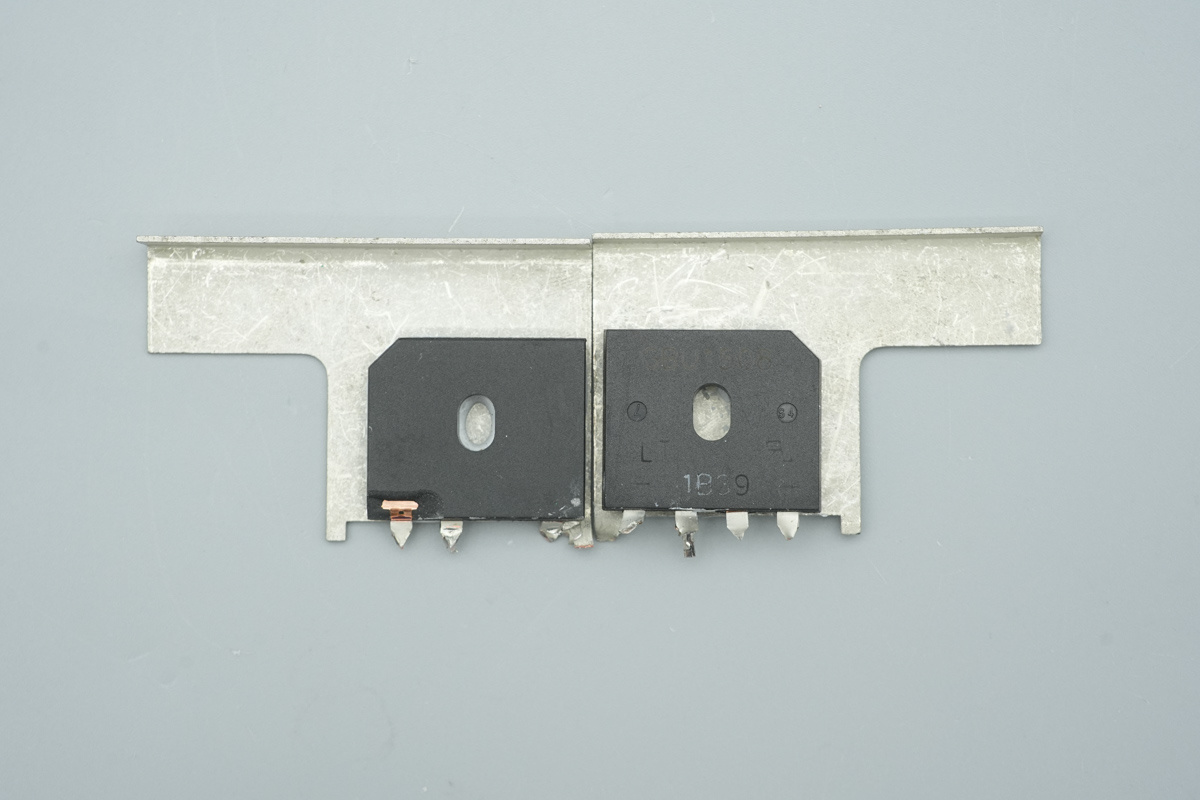
Two rectifier bridges are mounted and secured onto the heatsink.
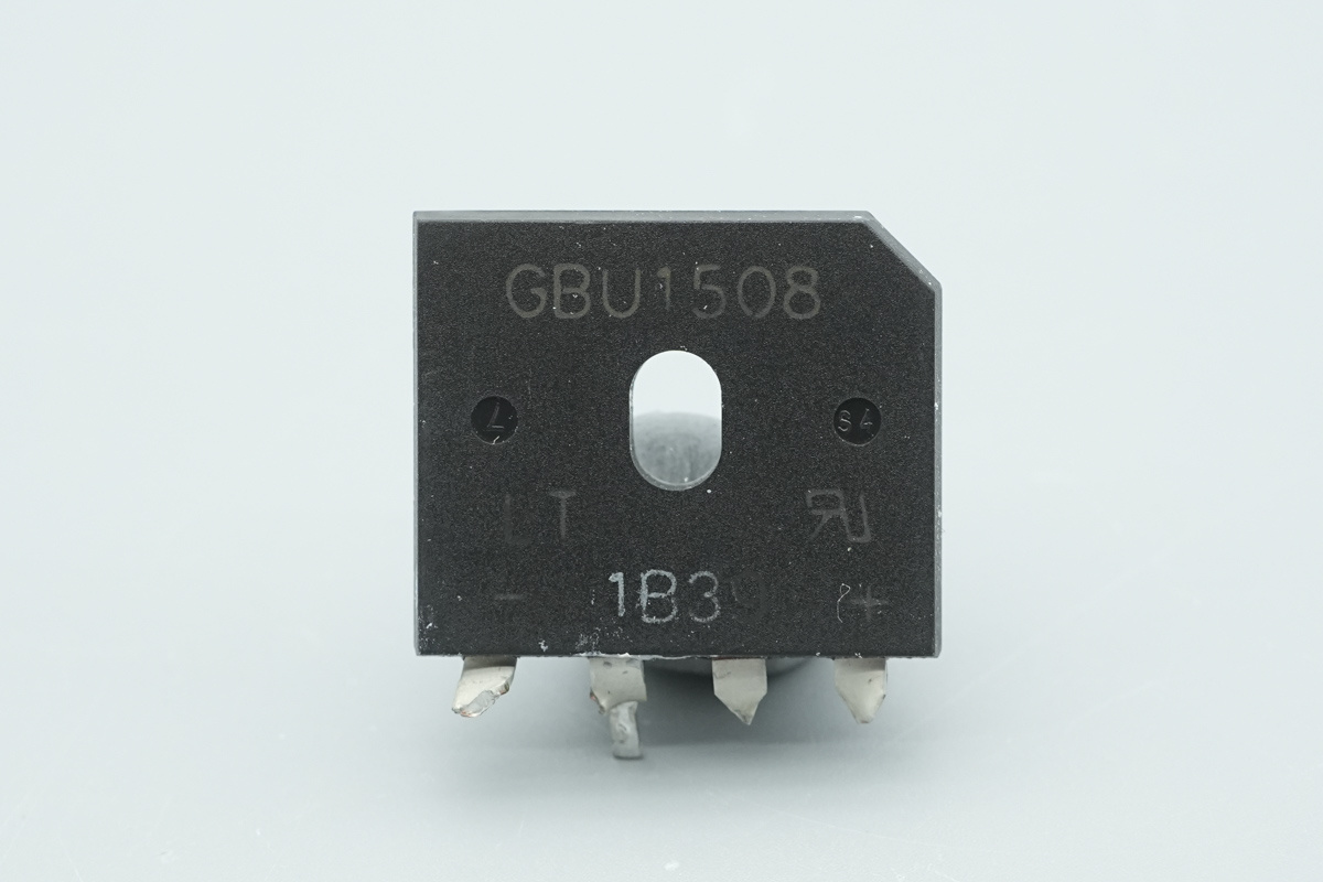
The rectifier bridge is from LITEON, model GBU1508, 15A 800V, housed in a GBU package.
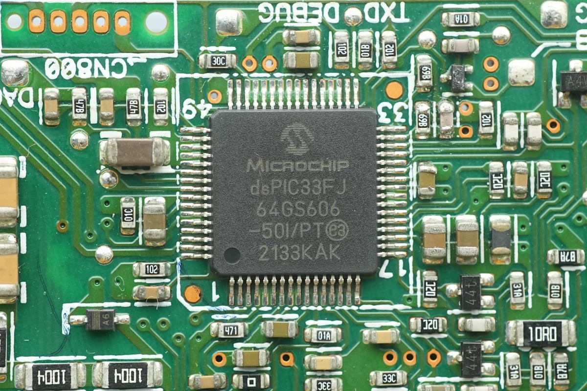
The PFC controller is from MICROCHIP, model dsPIC33FJ64GS606. It integrates a 16-bit DSPIC33F CPU, featuring 64KB of Flash memory, 9KB of RAM, a high-speed ADC, and 6 pairs of PWM drive signals. It is housed in a 64-pin TQFP package.
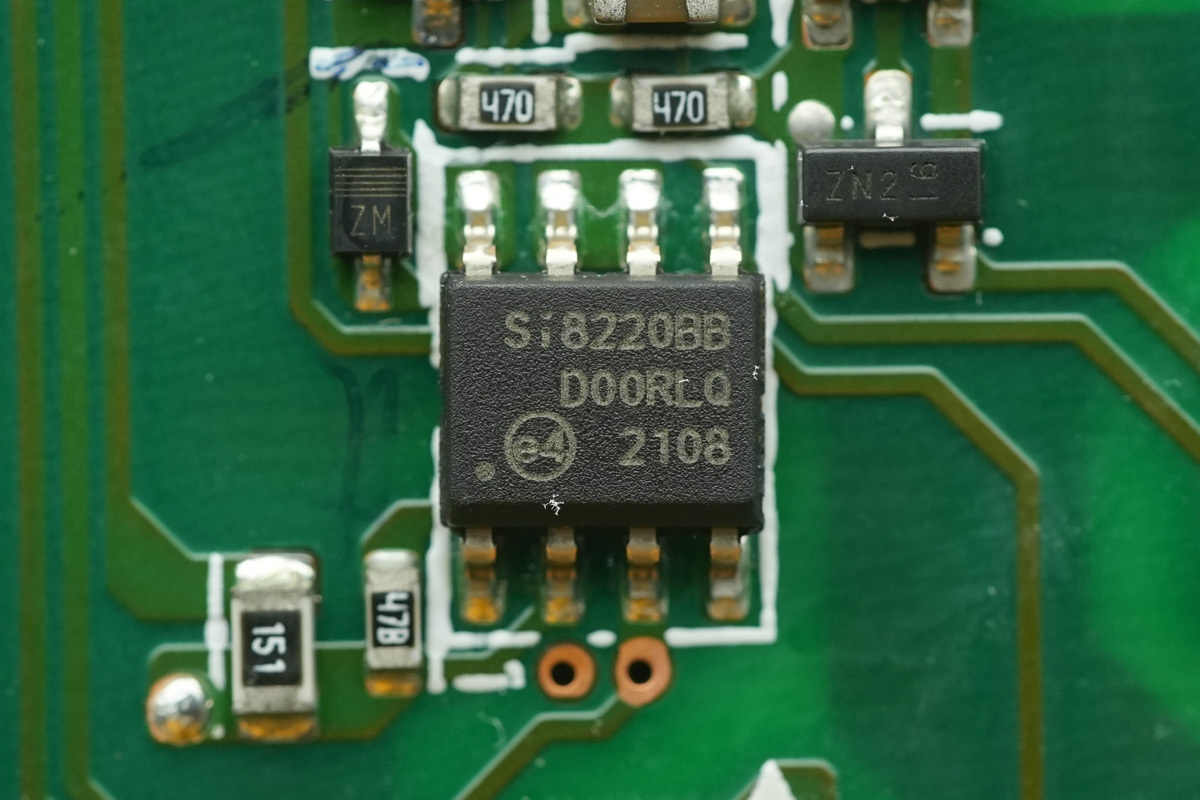
The driver is from SKYWORKS, model Si8220BB. It is an isolated driver with a 2.5A peak output current, featuring 2.5kVrms isolation capability. It supports an operating voltage range of 6.5V to 24V and an industrial operating temperature range of -40℃ to 125℃, housed in an SOIC-8 package.
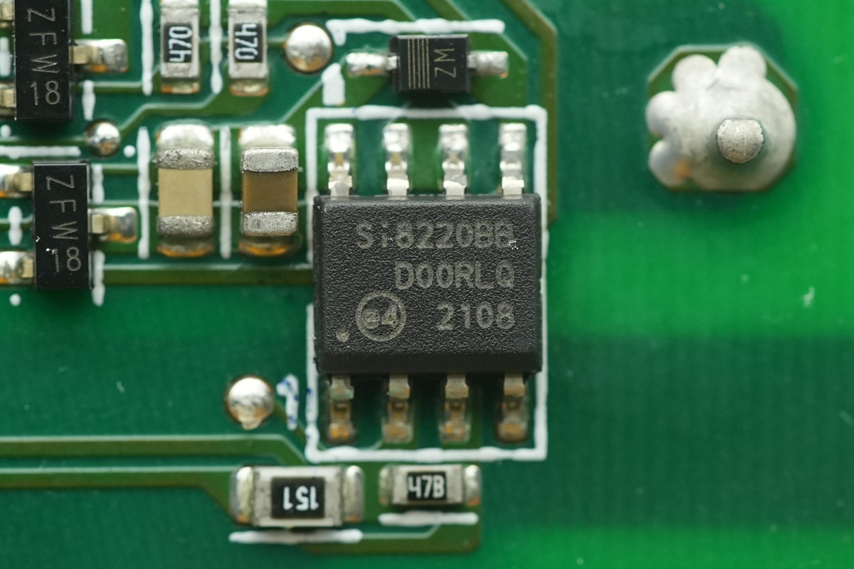
Another one shares the same model.
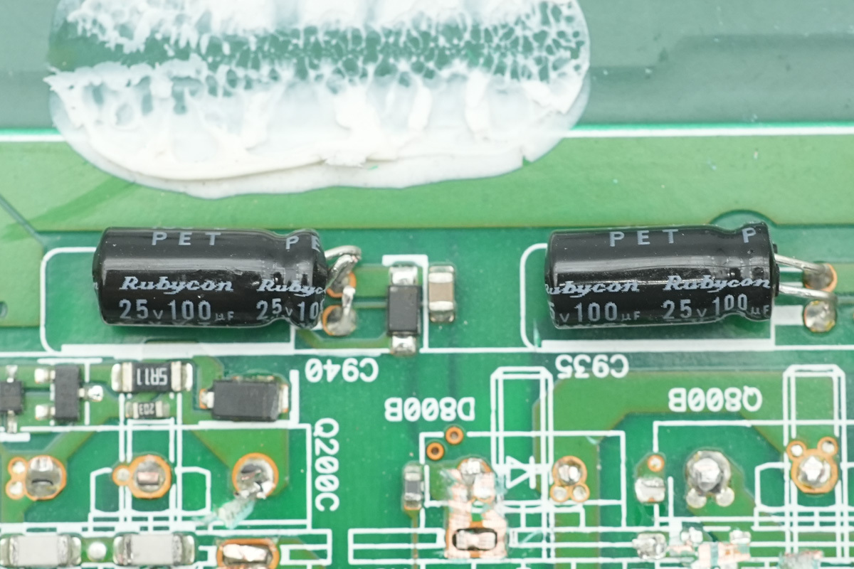
Two filtering caps are from Rubycon, 25V100μF.
The PFC switching MOSFET and PFC rectifier MOSFET are secured onto the heatsink.
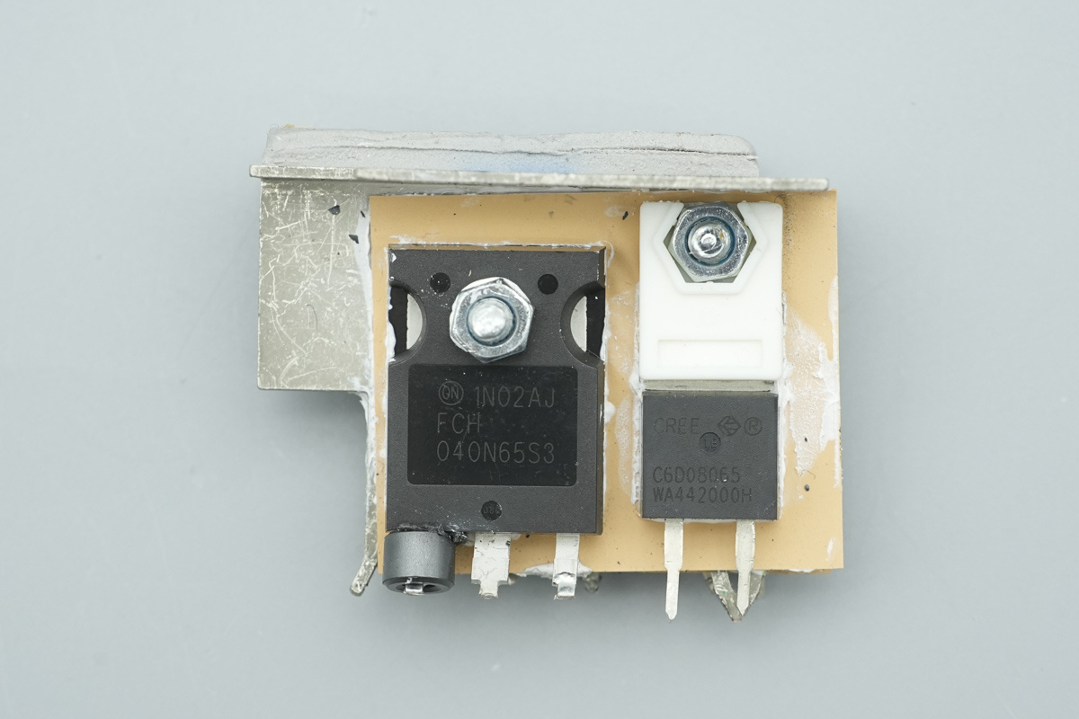
Additional PFC switching MOSFET and PFC rectifier MOSFET are secured on the opposite side of the heatsink.
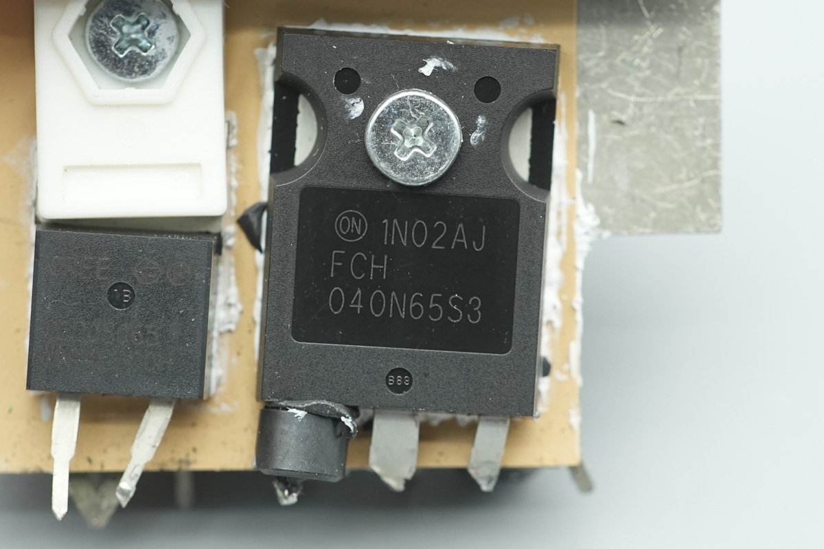
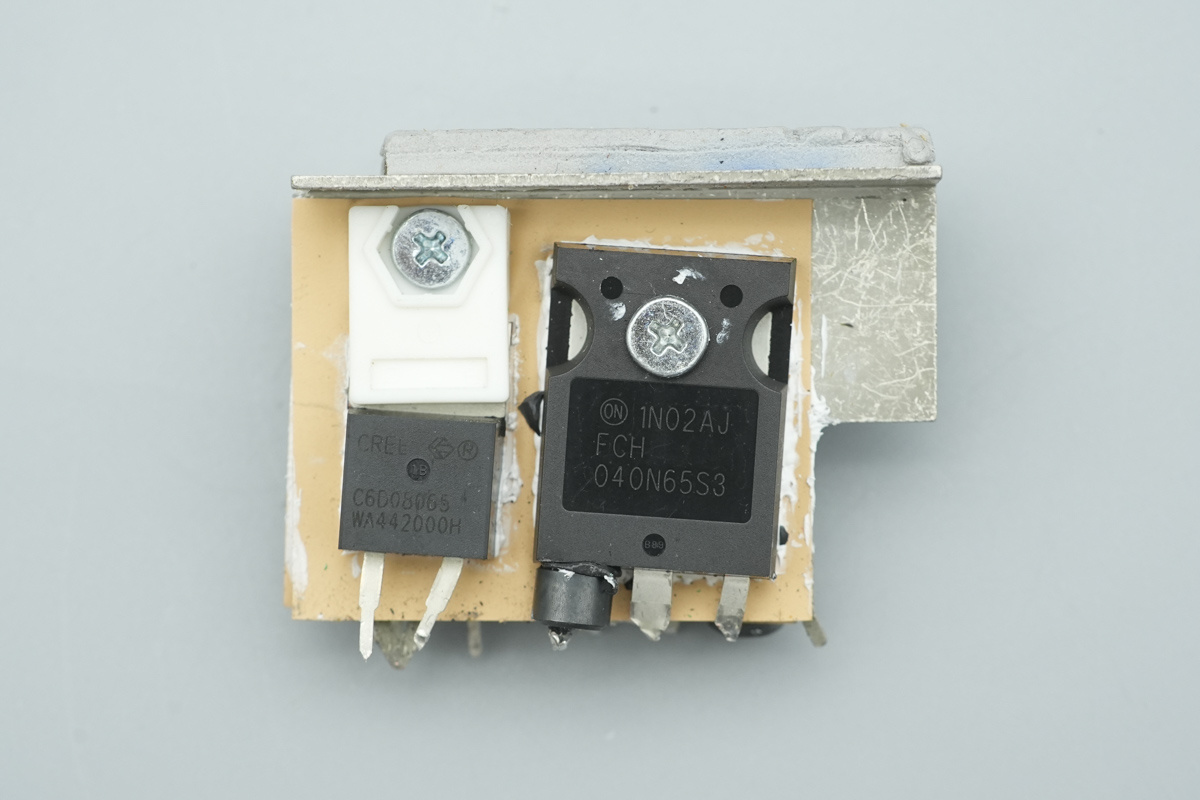
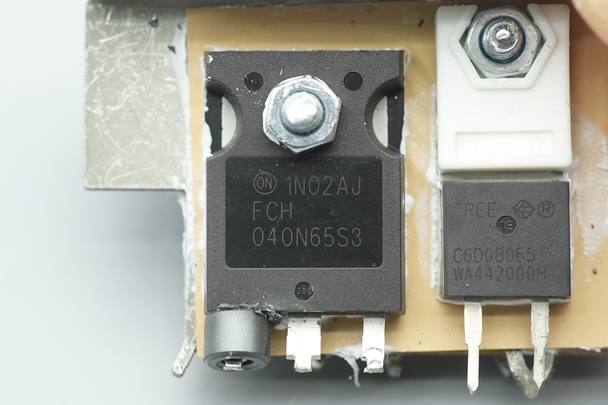
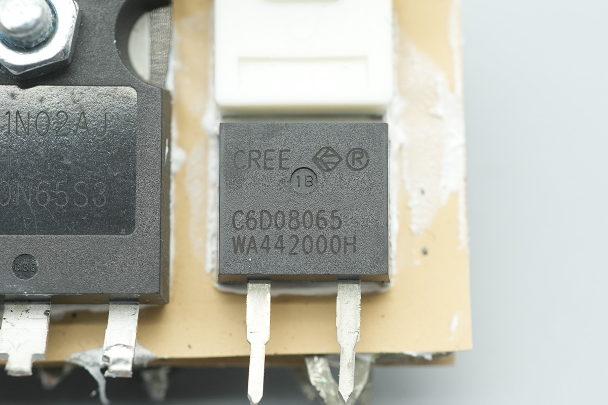
The PFC switching MOSFET is from onsemi, model FCH040N65S3, NMOS, 650V and 40mΩ, housed in a TO-247 package.
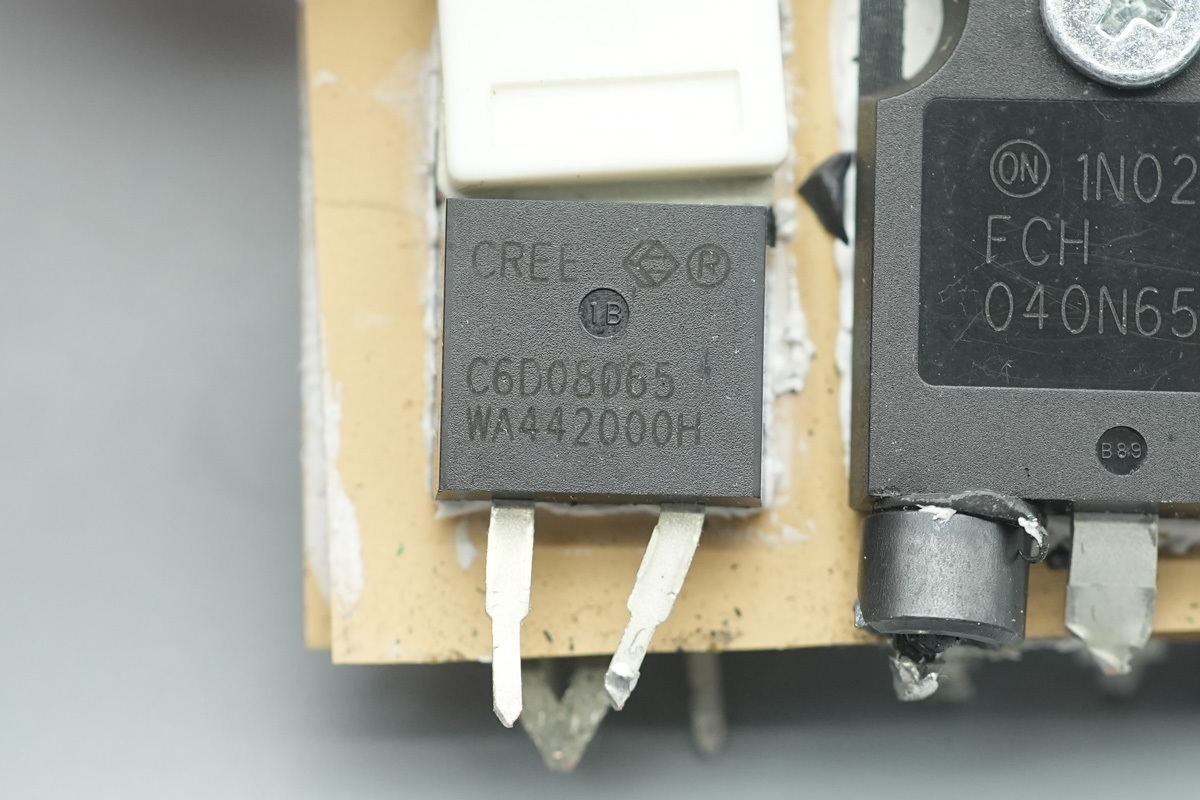
The PFC rectifier MOSFET is from Wolfspeed, model C6D08065A. It is a 6th-generation SiC Schottky diode, 650V and 8A, housed in a TO-220-2 package.
Another PFC switching MOSFET shares the same model.
Another PFC rectifier MOSFET shares the same model.
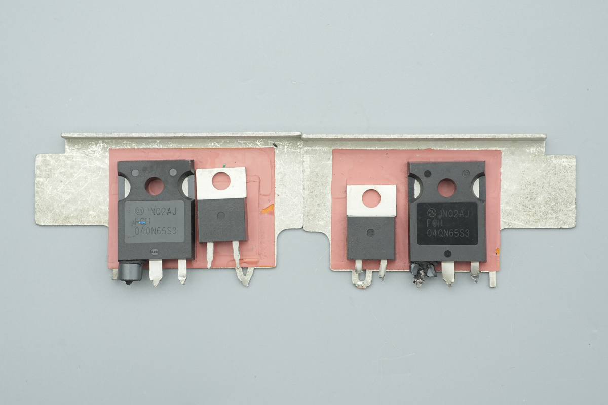
The PFC switching MOSFETs and PFC rectifier MOSFETs mounted on the other heatsink utilize the exact same model.
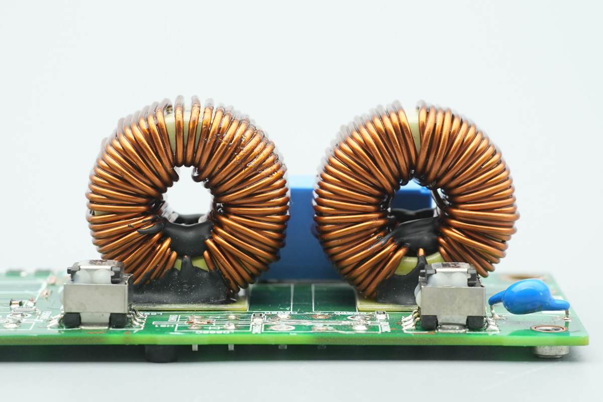
The PFC boost choke utilizes a toroidal core winding, with an insulating bakelite board installed at the bottom.
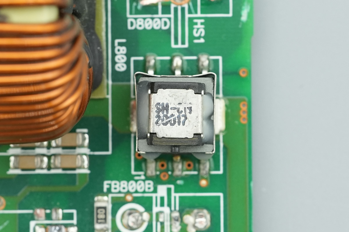
A SMD current transformer is utilized to accurately detect and monitor the current flowing through the PFC boost choke.
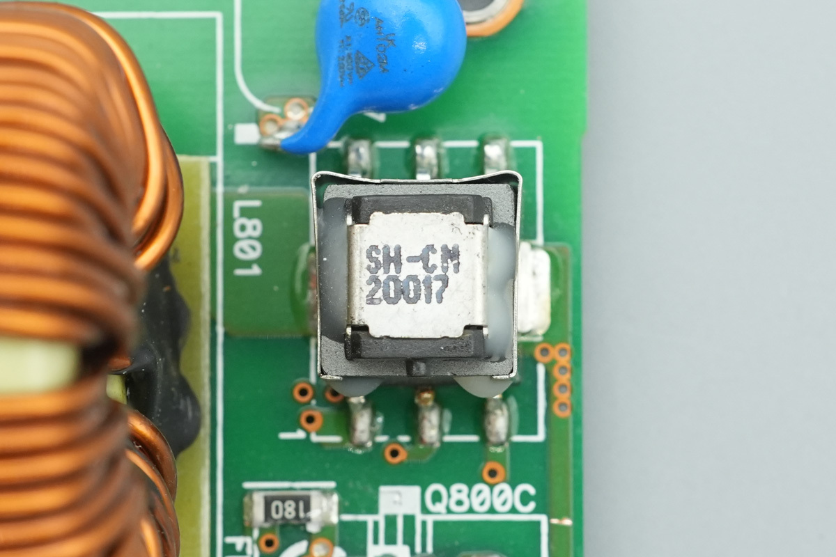
Two SMD current transformers correspond to two PFC boost chokes.
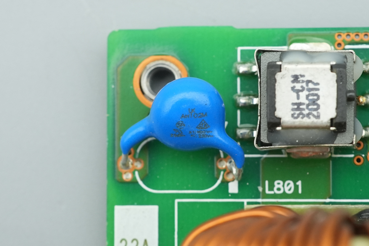
The blue Y-cap is from WTC, model AH102M.
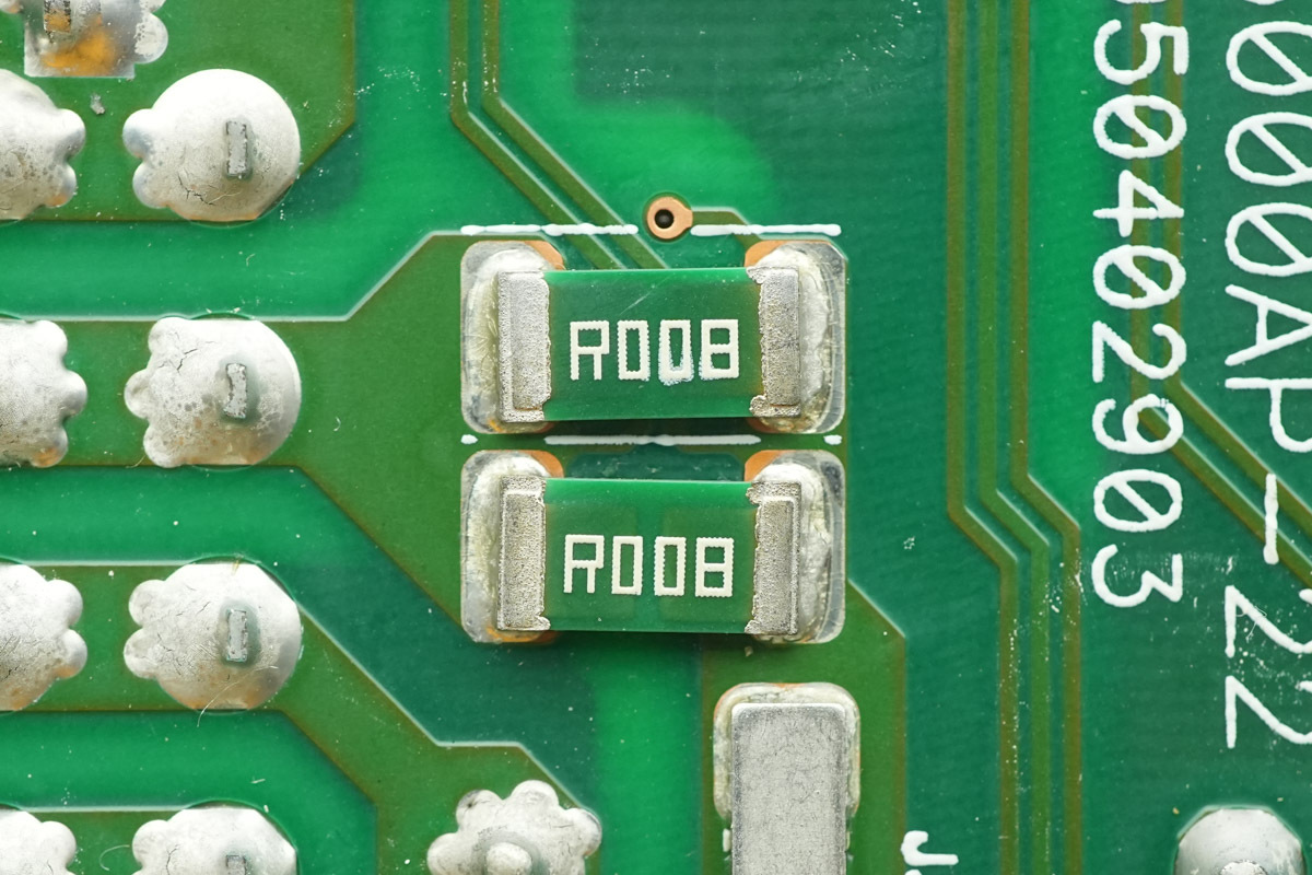
Two 8mΩ resistors are connected in parallel for input current detection.
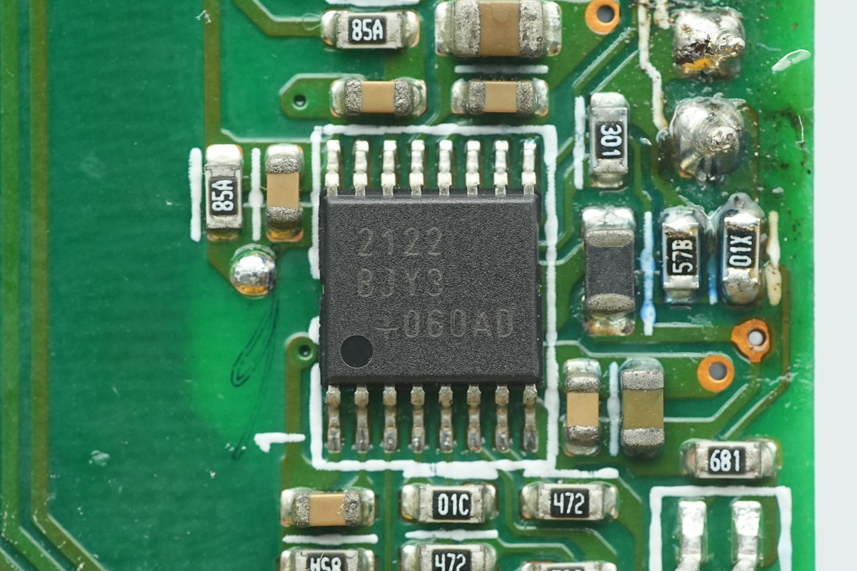
The load metering IC is from ADI, marked BJY3, housed in a 16 TSSOP package.
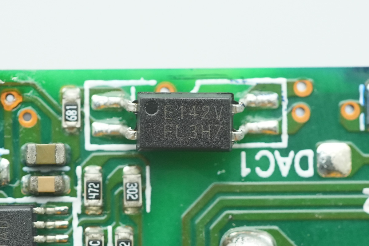
The isolation optocoupler is from Everlight, model EL3H7.
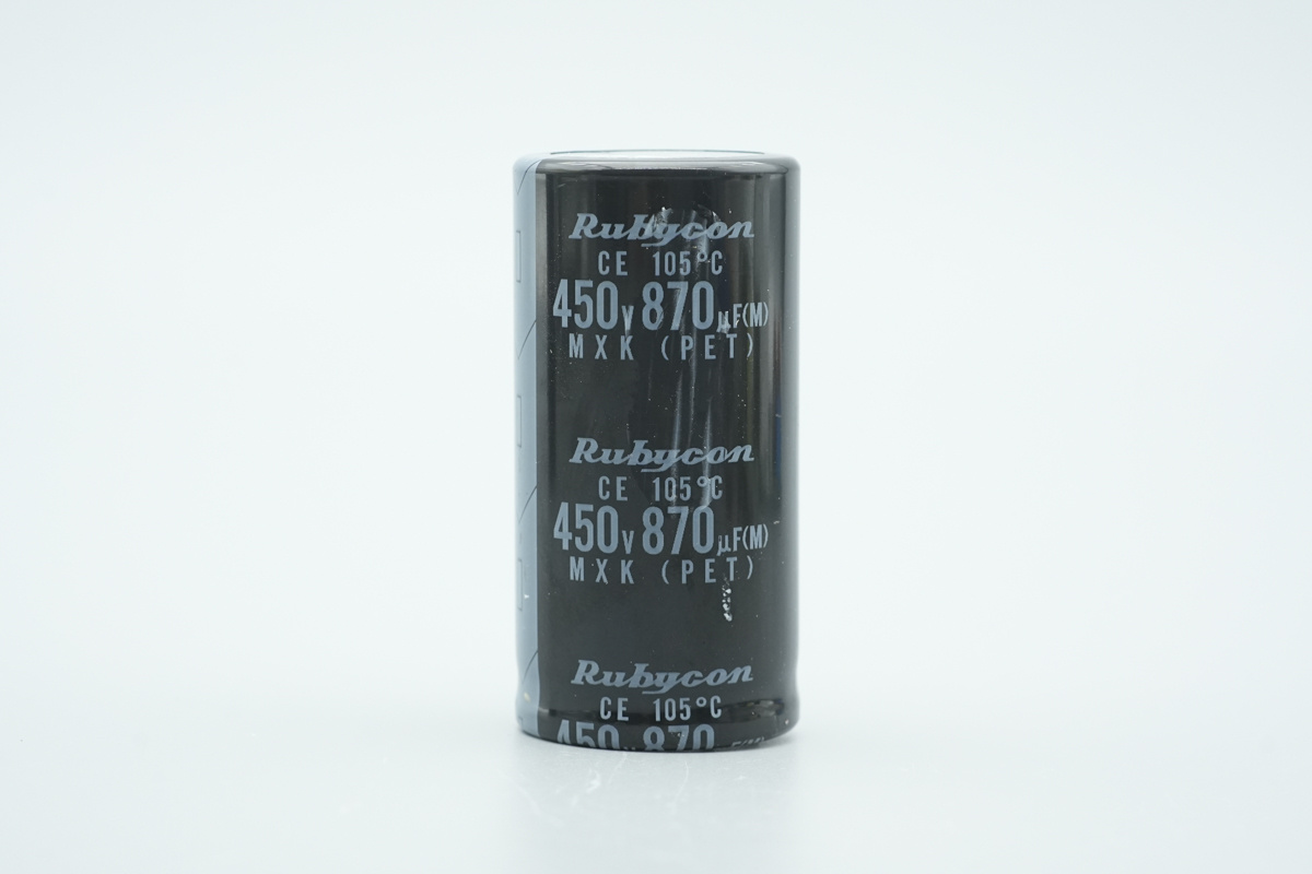
The high-voltage filter cap is from Rubycon, belonging to the MXK series of miniature aluminum electrolytic caps, spec 450V and 870μF.
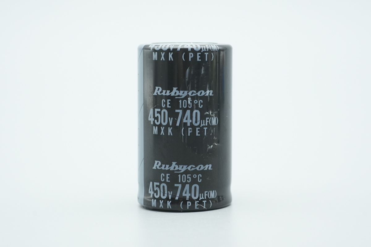
The other one is rated at 450V 740μF, with a total capacitance of 1610μF.
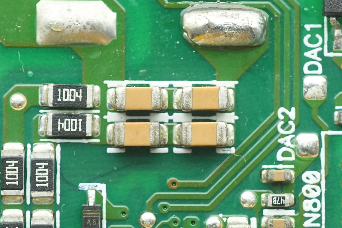
The MLCCs are connected in parallel with the high-voltage filter caps.
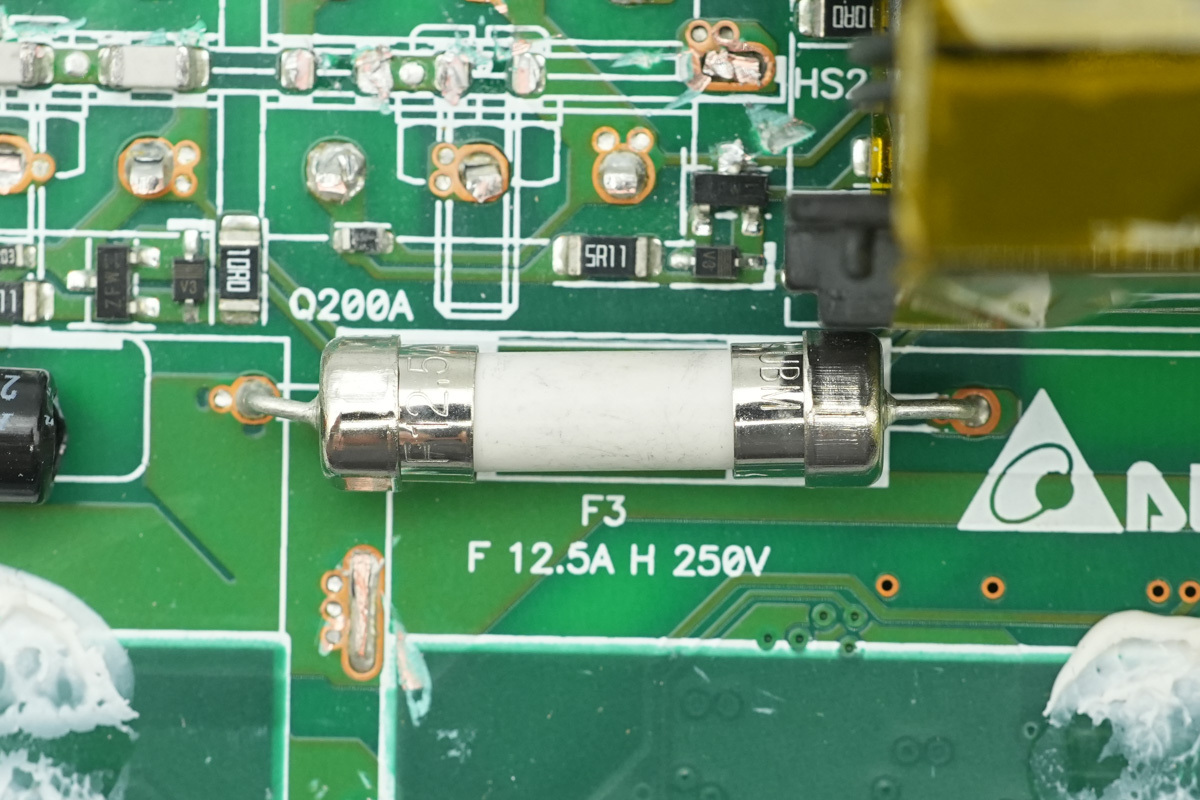
The fuse, spec 12.5A 250V, and is used for LLC-level OVP.
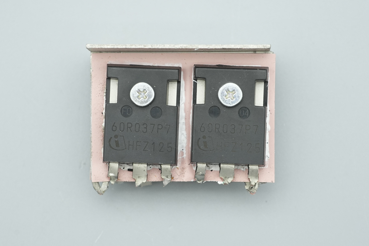
Two LLC switching MOSFETs are located on the front of the heatsink.
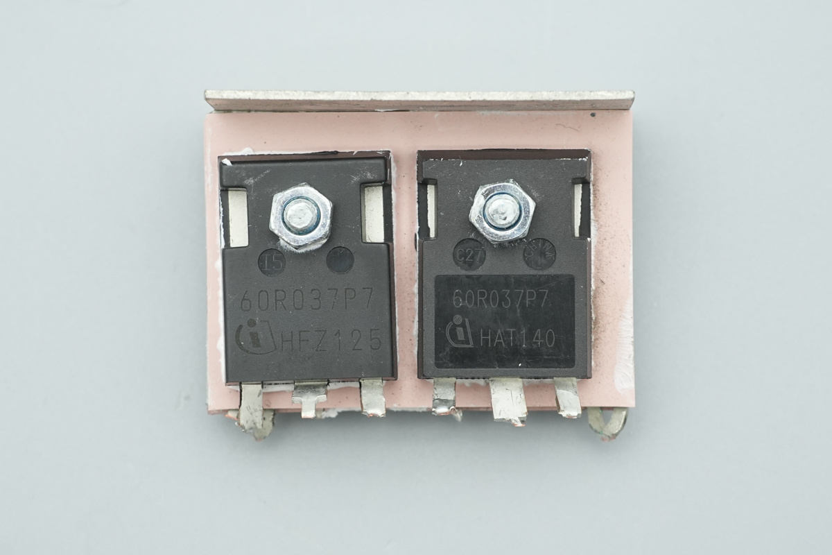
Two LLC switching MOSFETs are also located on the back of the heatsink.
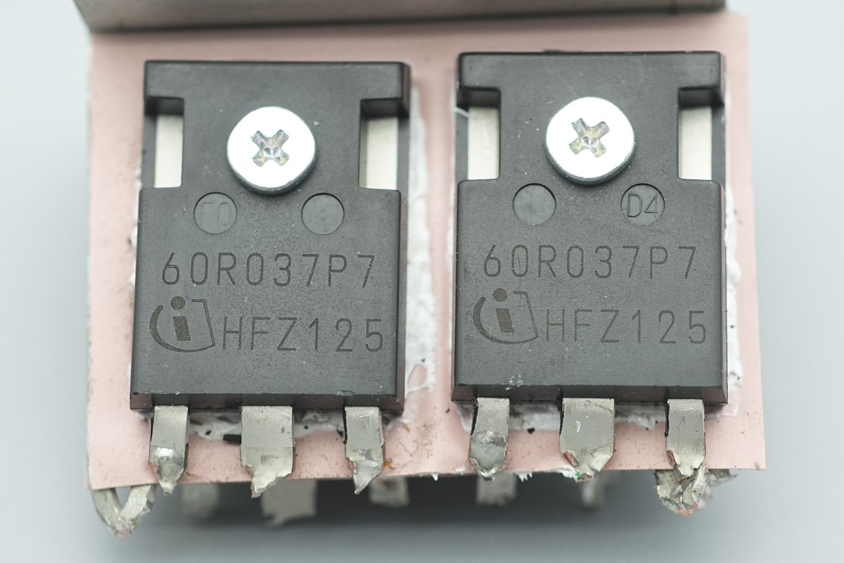
The LLC switching MOSFETs are from Infineon, model IPW60R037P7, specially the CoolMOS P7 series, NMOS, 650V and 37mΩ, and in a TO 247-3 package.
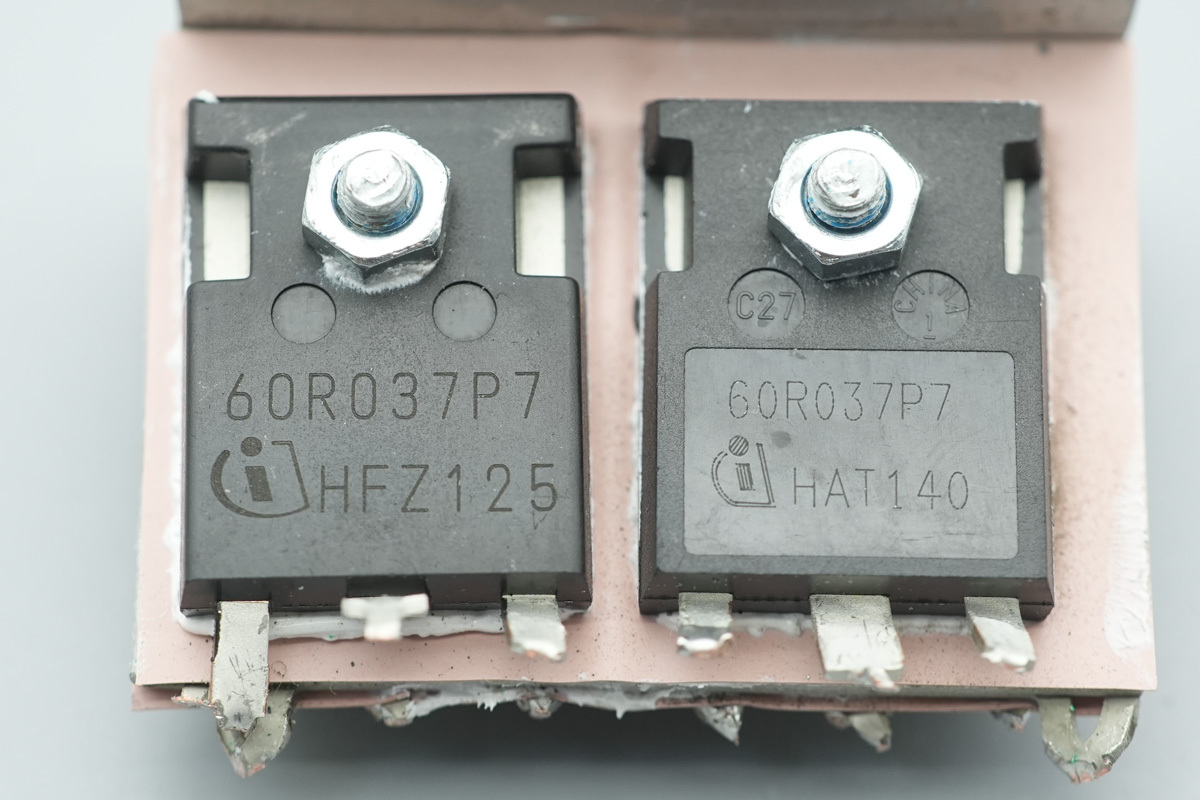
The two LLC switching MOSFETs on the other side are of the same model.
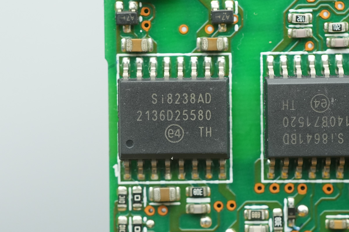
The driver is from SKYWORKS, model Si8238AD. It is a dual-channel isolated gate driver featuring a robust 4A peak output current and a 5kVrms input-to-output isolation rating. It supports up to 1500V peak differential voltage between the drivers, accommodates switching frequencies up to 8MHz, and is housed in a wide-body SOIC-16WB package.
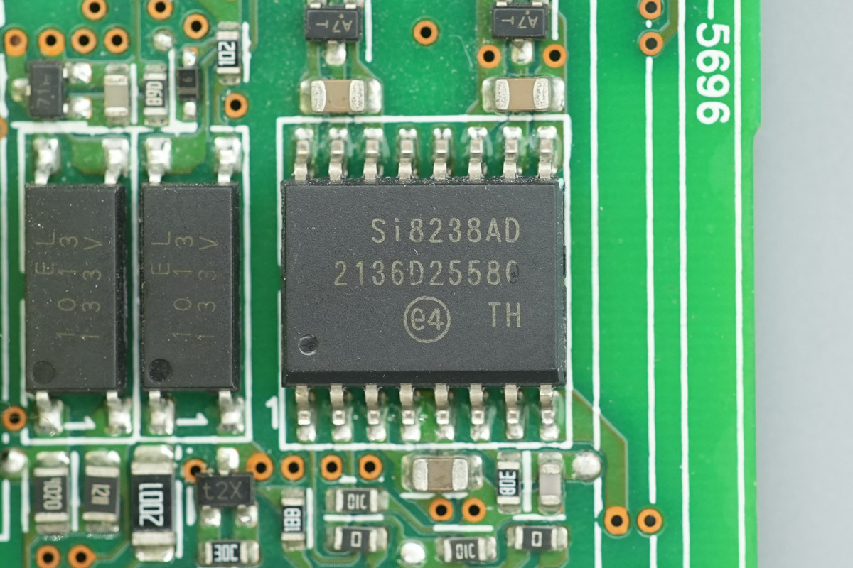
Another one shares the same model.
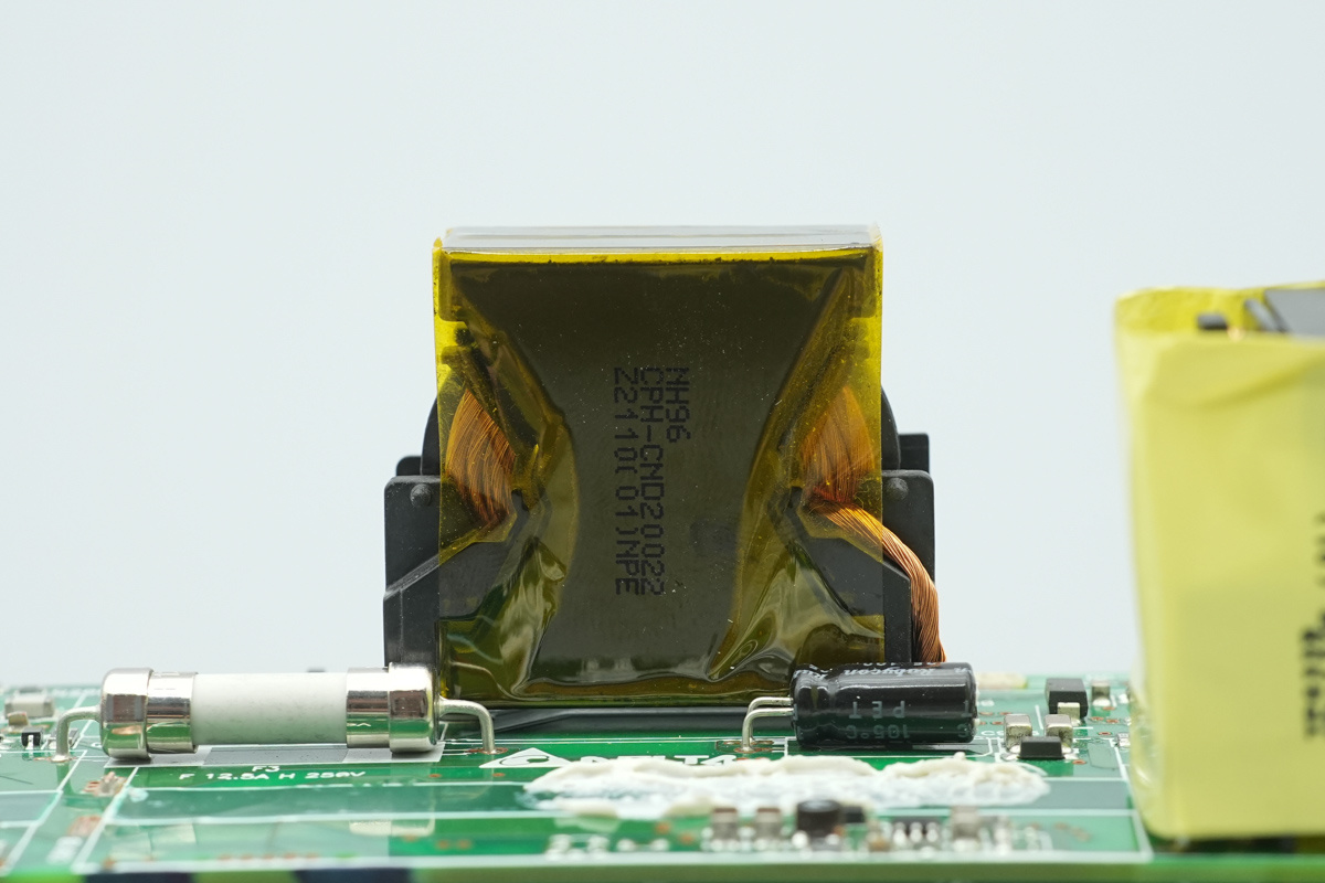
The LLC resonant choke is wound using Litz wire.
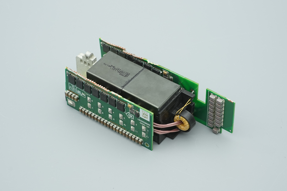
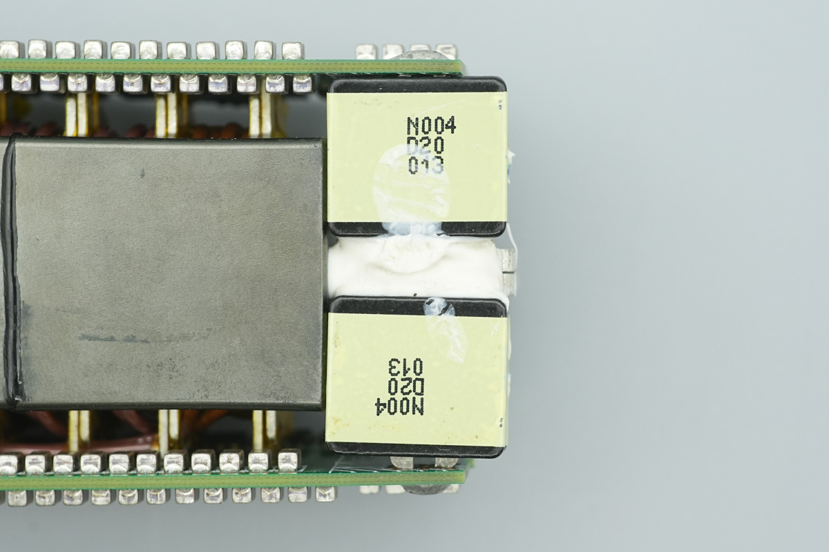
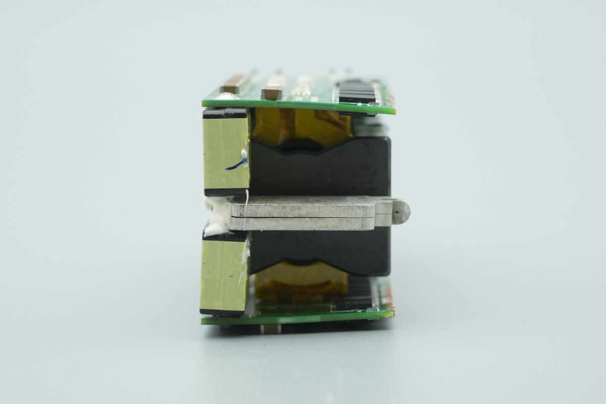
Rectifier filter PCBs are soldered to both sides of the transformer. The input end is equipped with resonant caps and a current transformer.
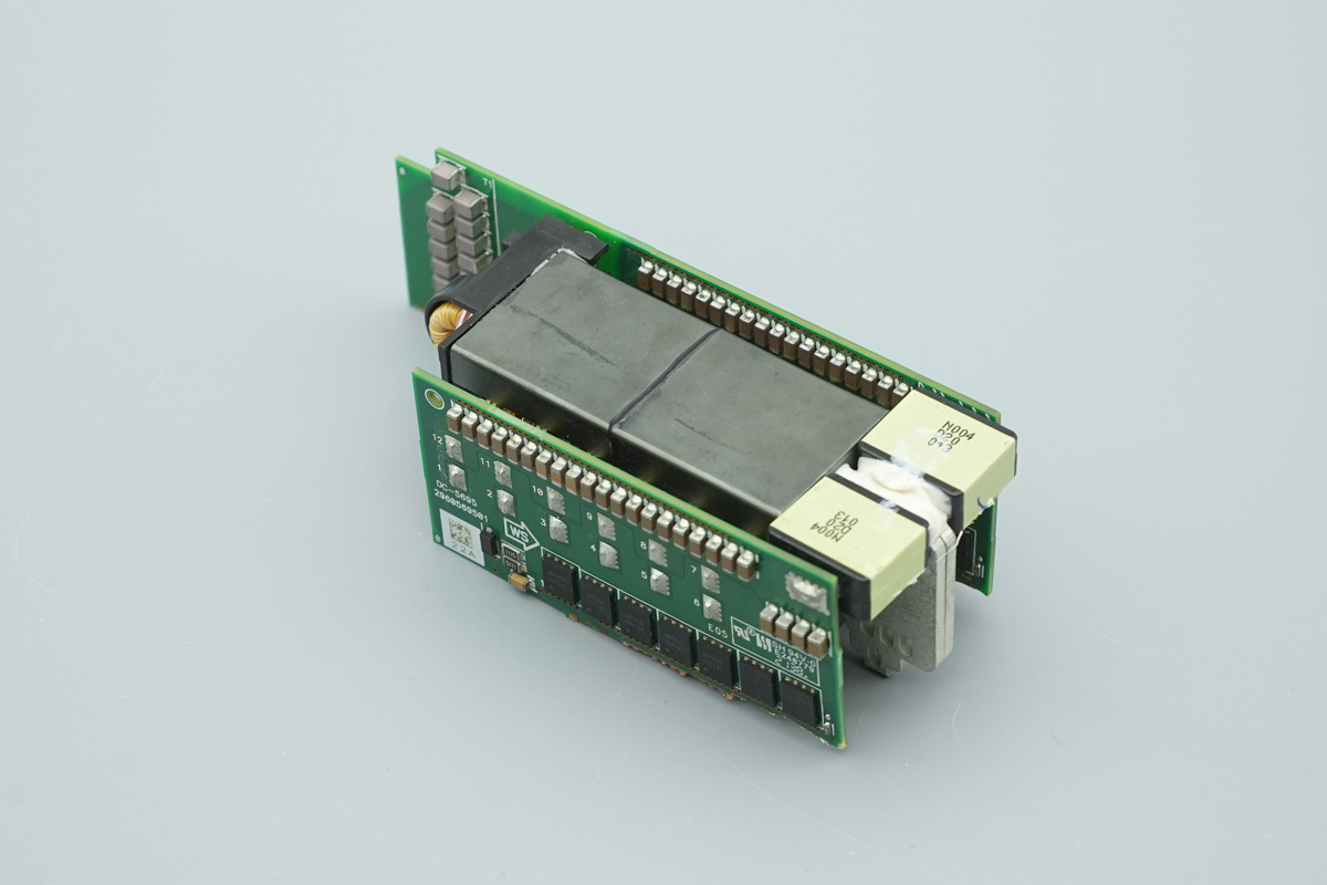
The output end is equipped with the filtering chokes.
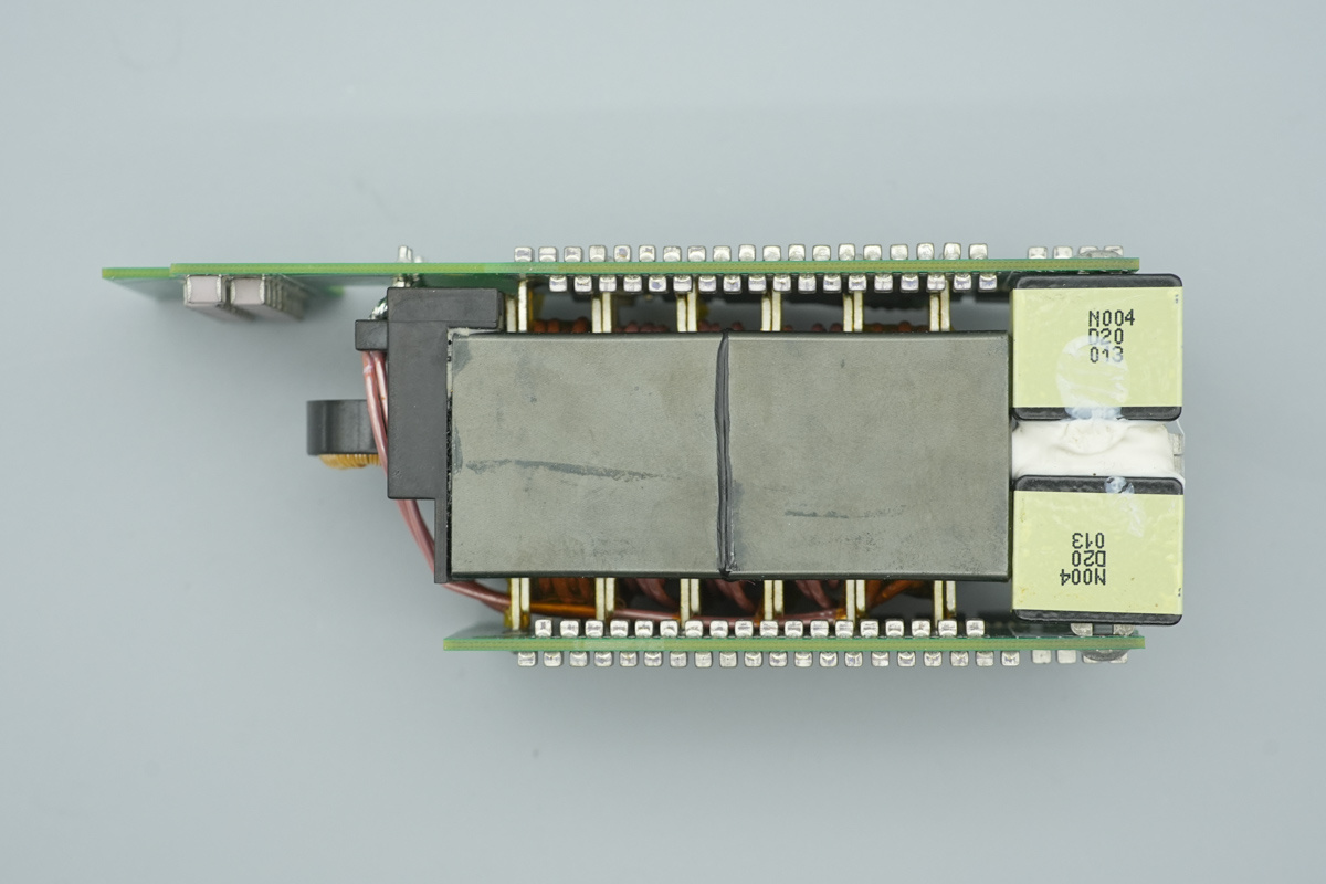
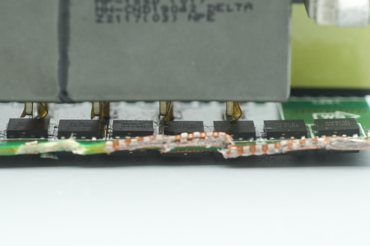
The secondary winding of the transformer is connected to the flank PCBs via heavy-duty copper tabs.
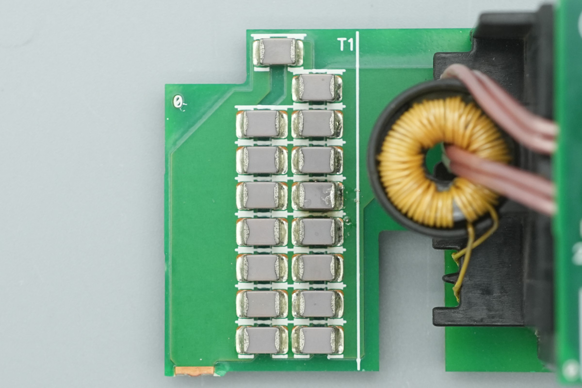
The LLC resonant cap uses an NPO cap.
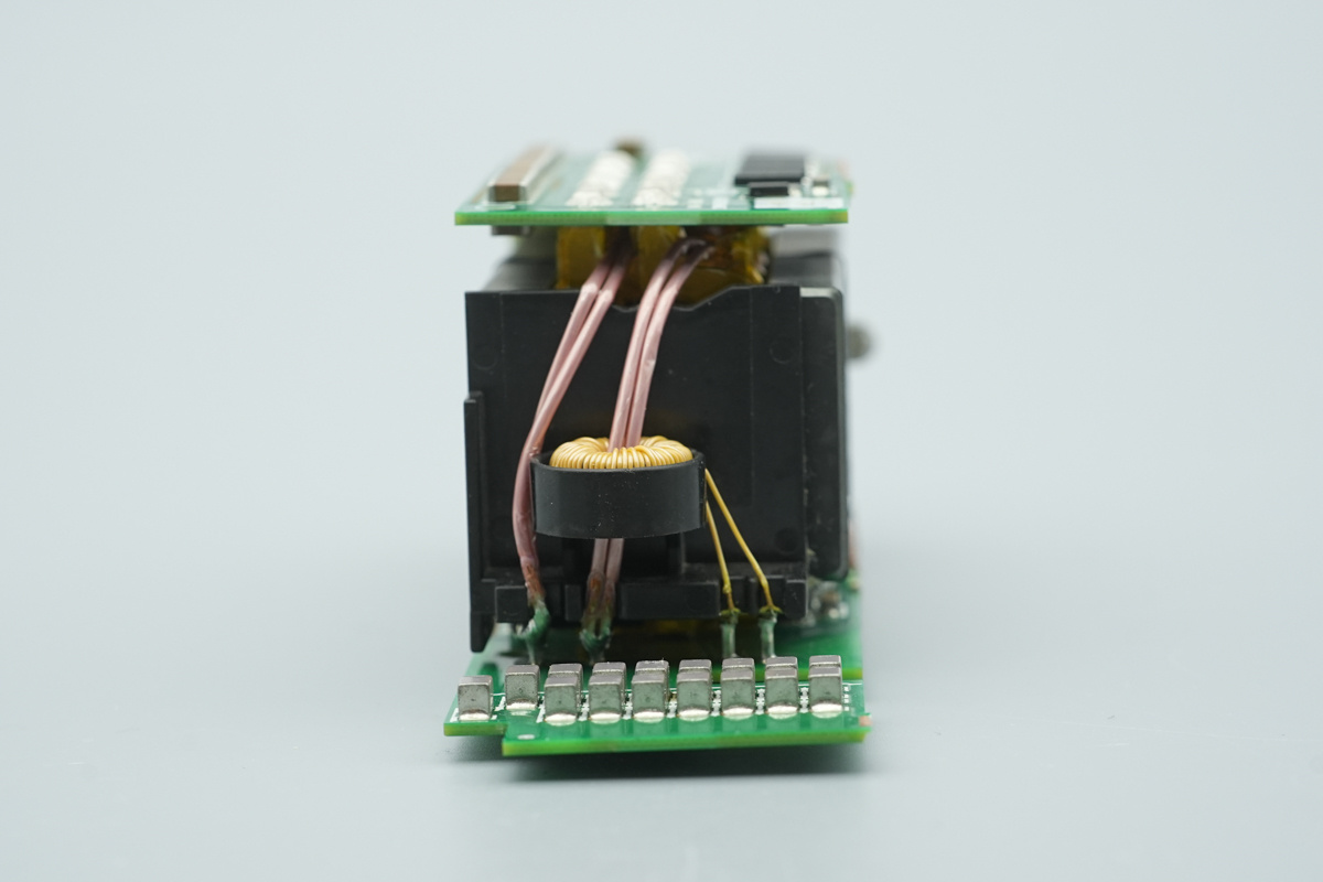
The primary winding is wound with Litz wire and is equipped with a current transformer.
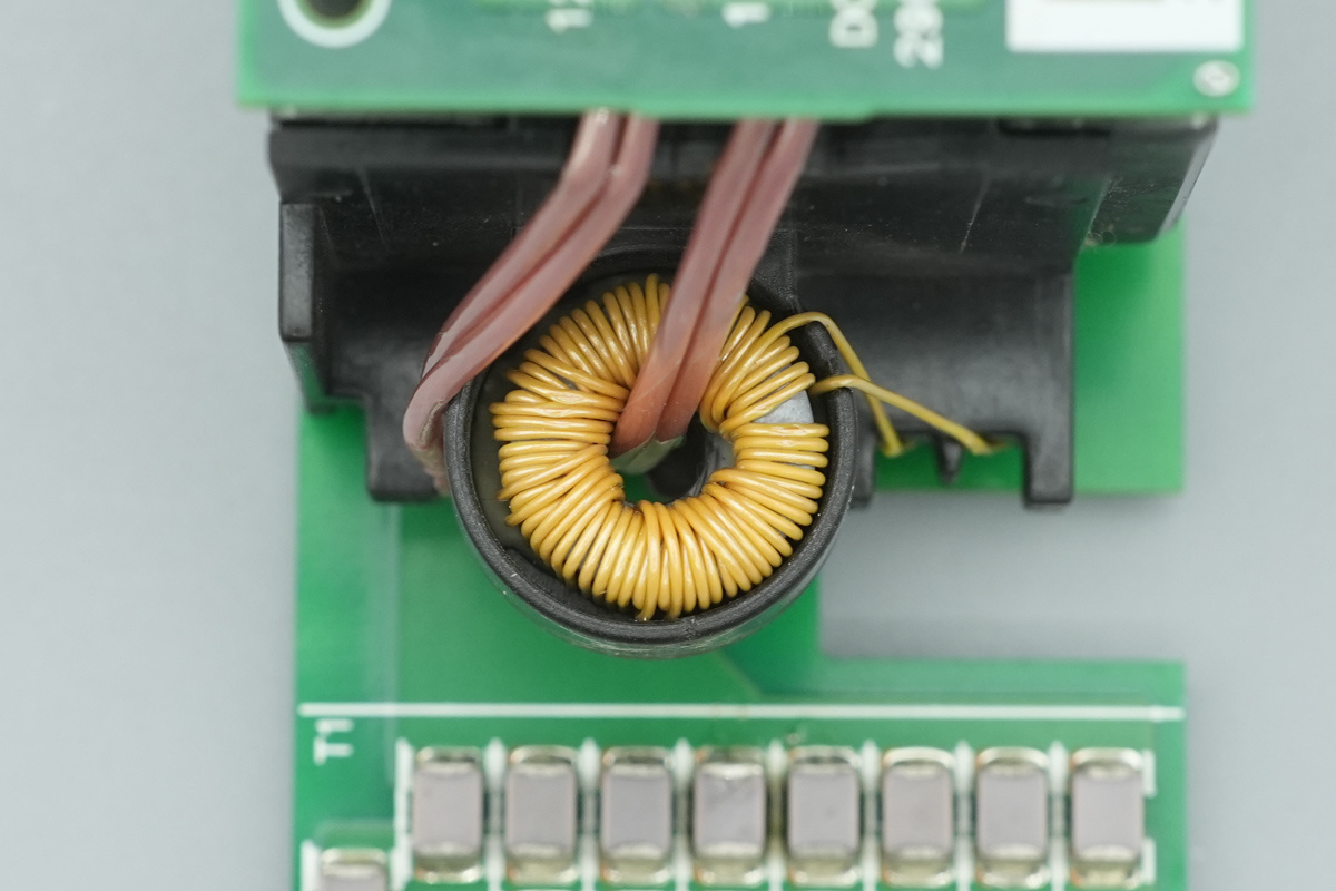
The current transformer is wound with insulated wire.
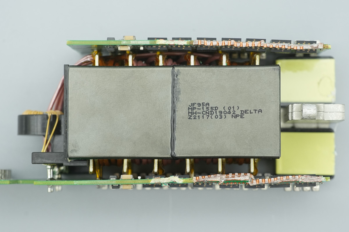
The transformer core is branded with the Delta logo.
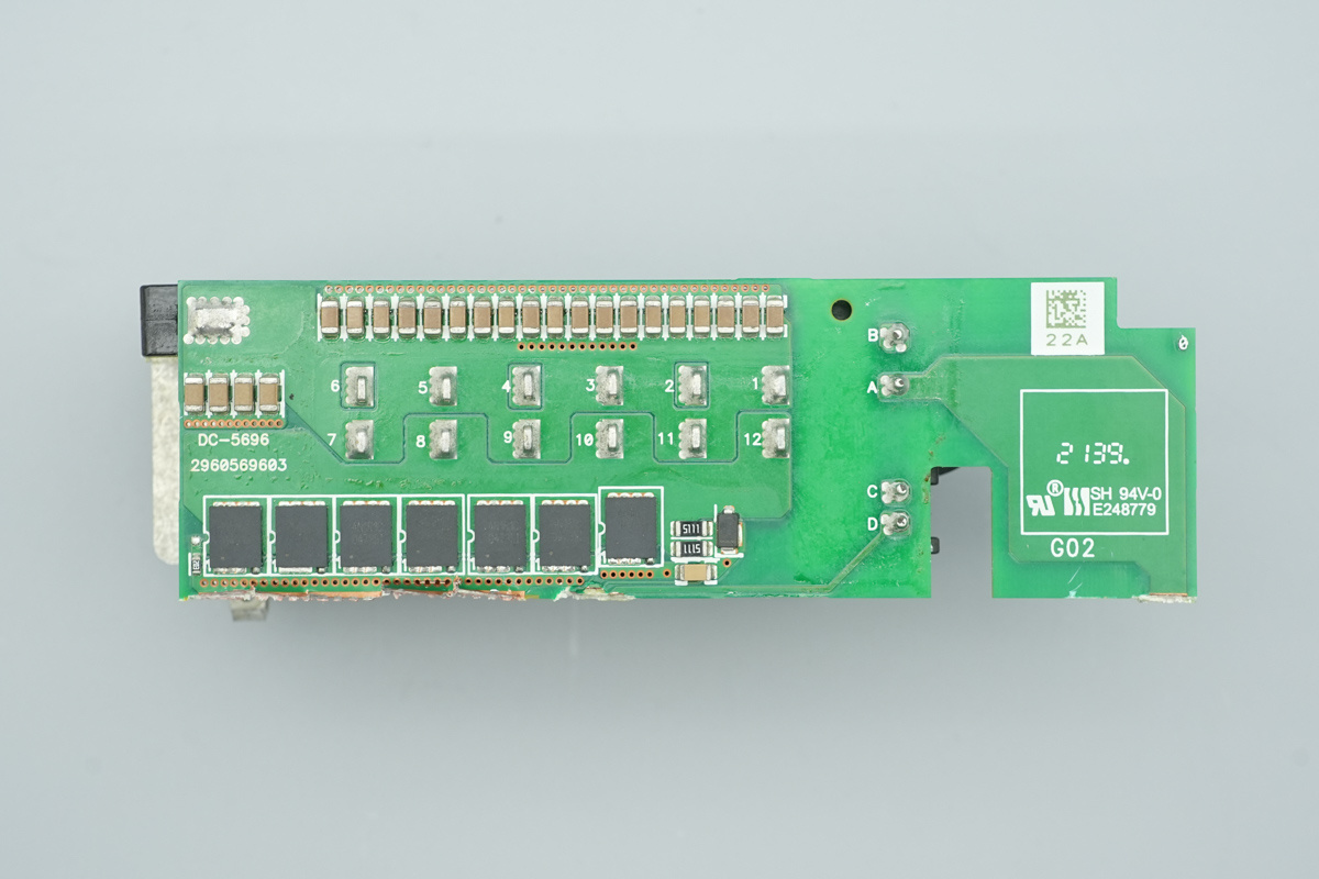
The MLCCs are located above the side of the PCB, and synchronous rectifier MOSFETs are located below it.
The other side of the PCB also has MLCCs and synchronous rectifier MOSFETs.
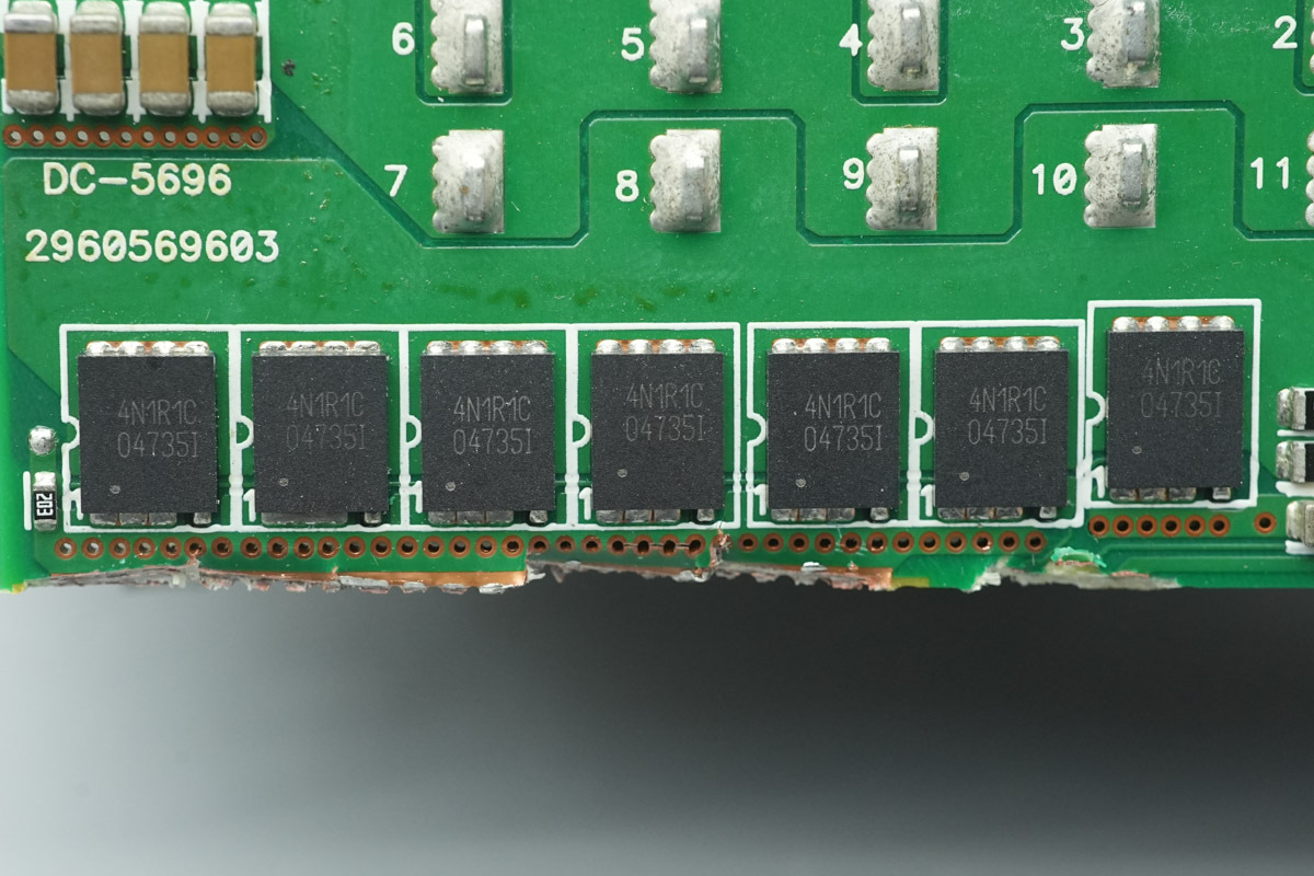
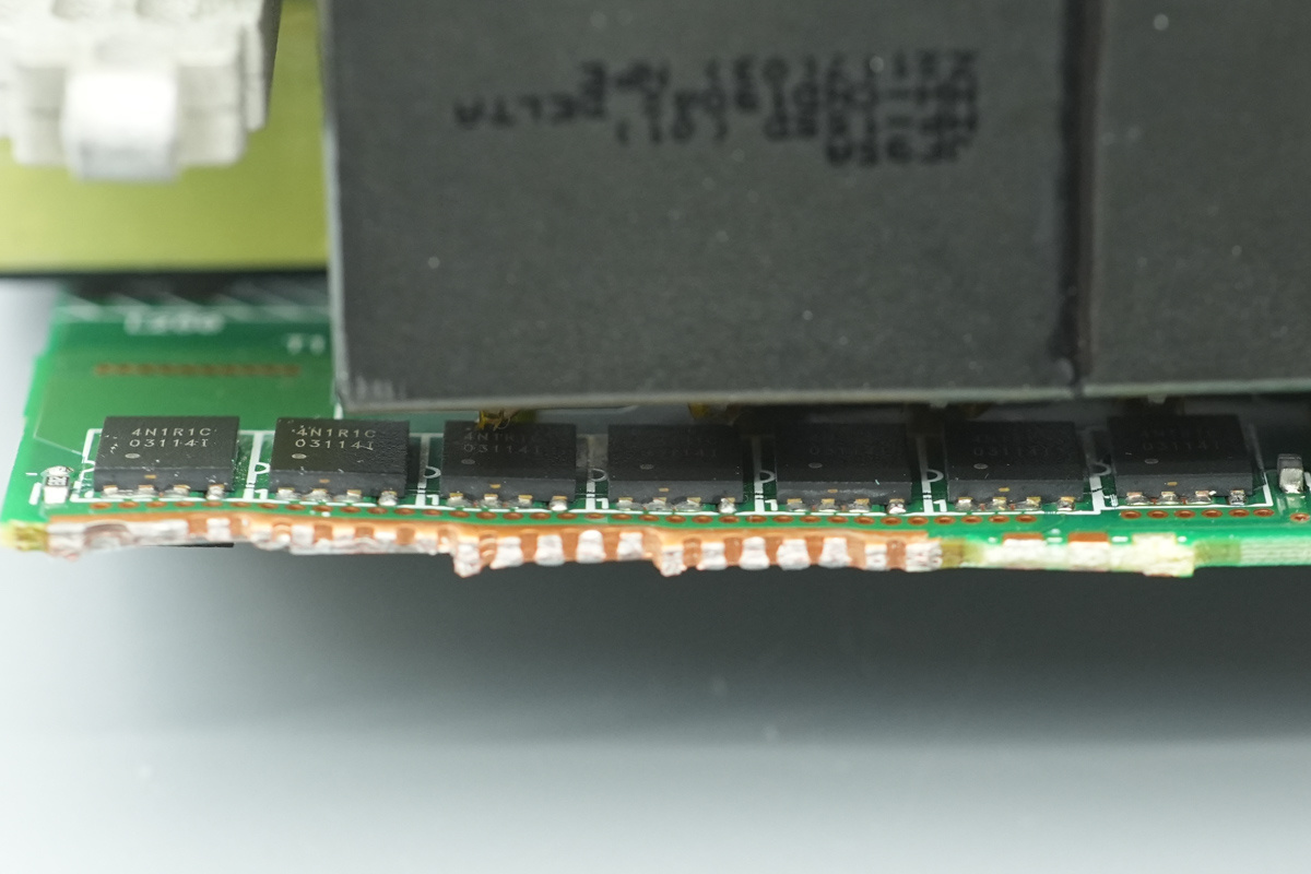
The synchronous rectifier MOSFETs are from APEC, marked 4N1R1C, model AP4N1R1CDT-A, NMOS, 45V and 1.15mΩ, and uses a PDFN5*6 package.
The other side of the PCB features 7 synchronous rectifier MOSFETs of the same model.
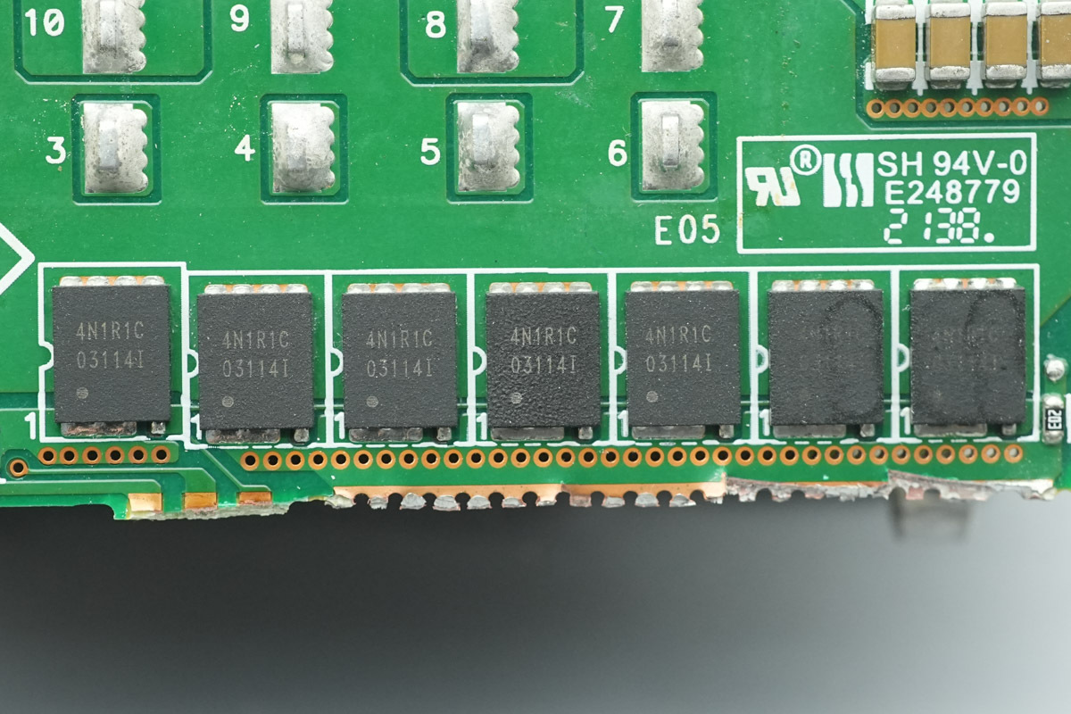
The other PCB has the synchronous rectifier MOSFETs of the same model.
The other side of the PCB features 7 synchronous rectifier MOSFETs of the same model.
The output end is equipped with filtering chokes.
The filtering chokes are connected to the bottom PCB via copper strips.
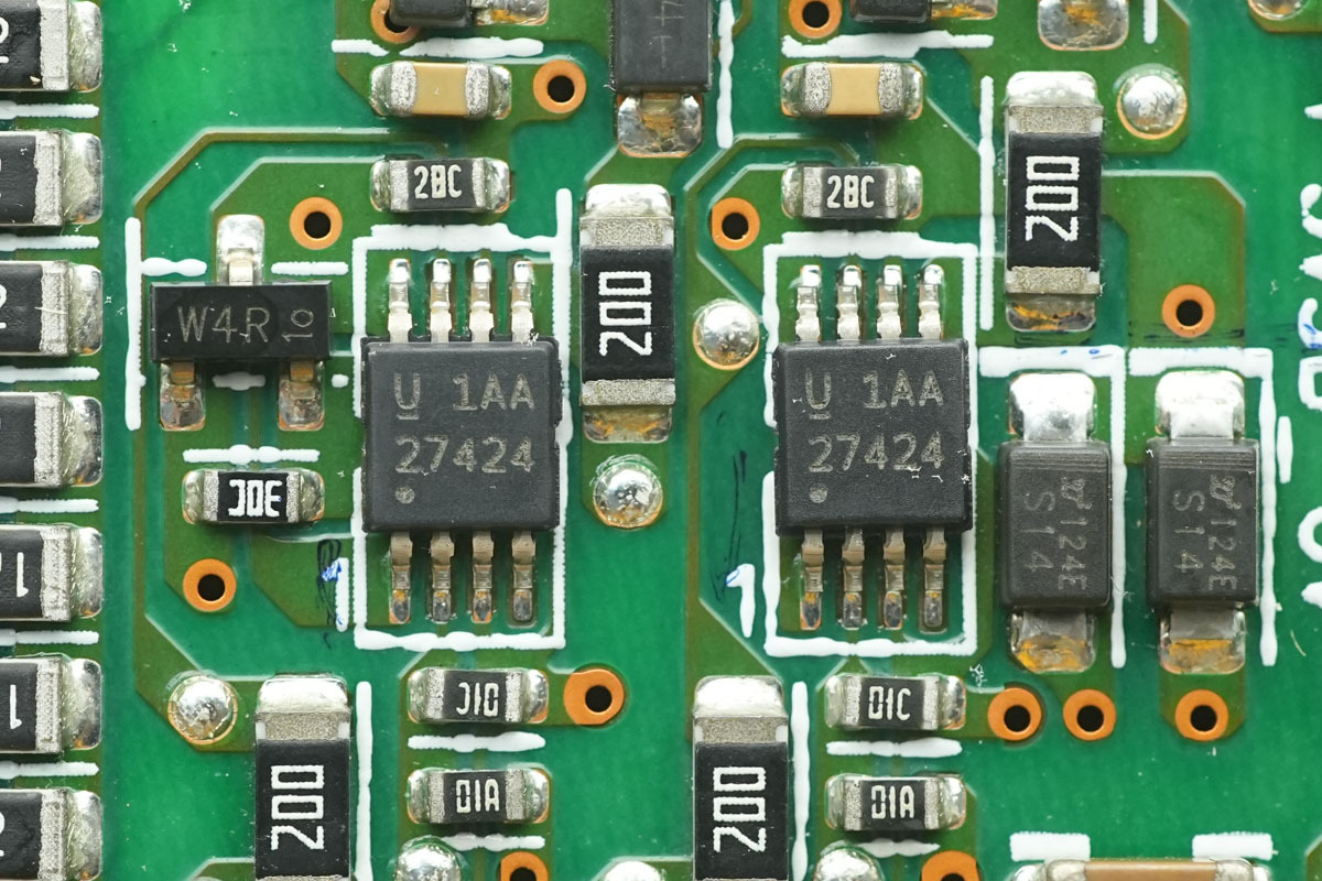
The synchronous rectifier MOSFETs are driven by a dual-channel high-speed gate driver from TI, model UCC27424. Capable of delivering a peak output current of 4A, it is housed in a VSSOP-8 package.
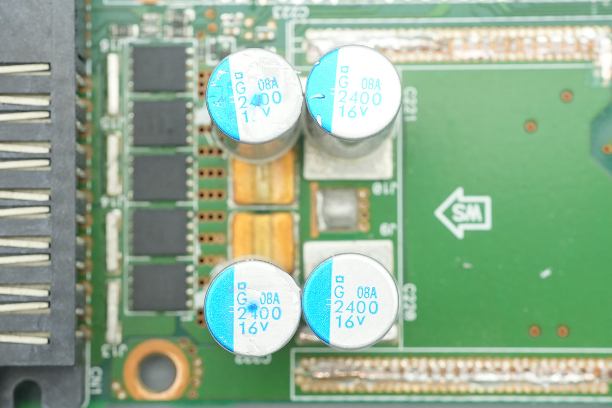
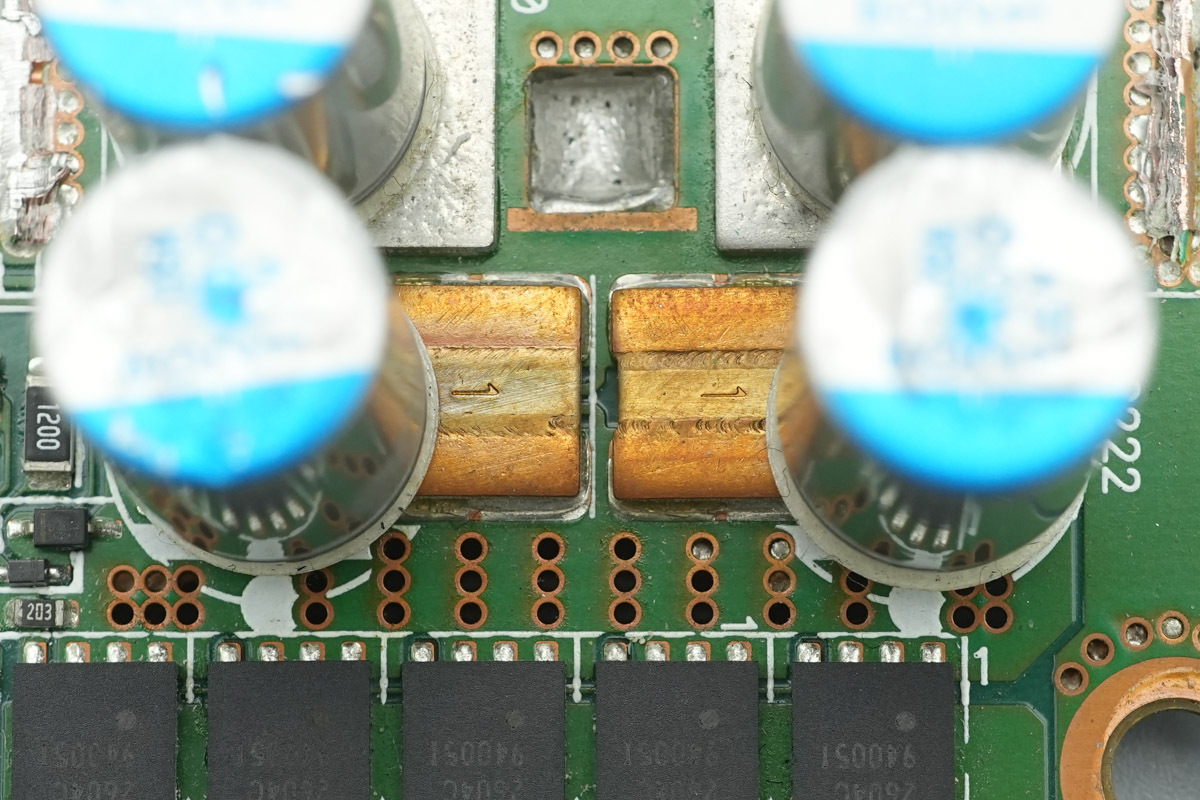
The filtering caps are from NCC, belonging to the PSG series of conductive polymer aluminum solid electrolytic caps, spec 2400μF 16V.
Two current sense resistors.
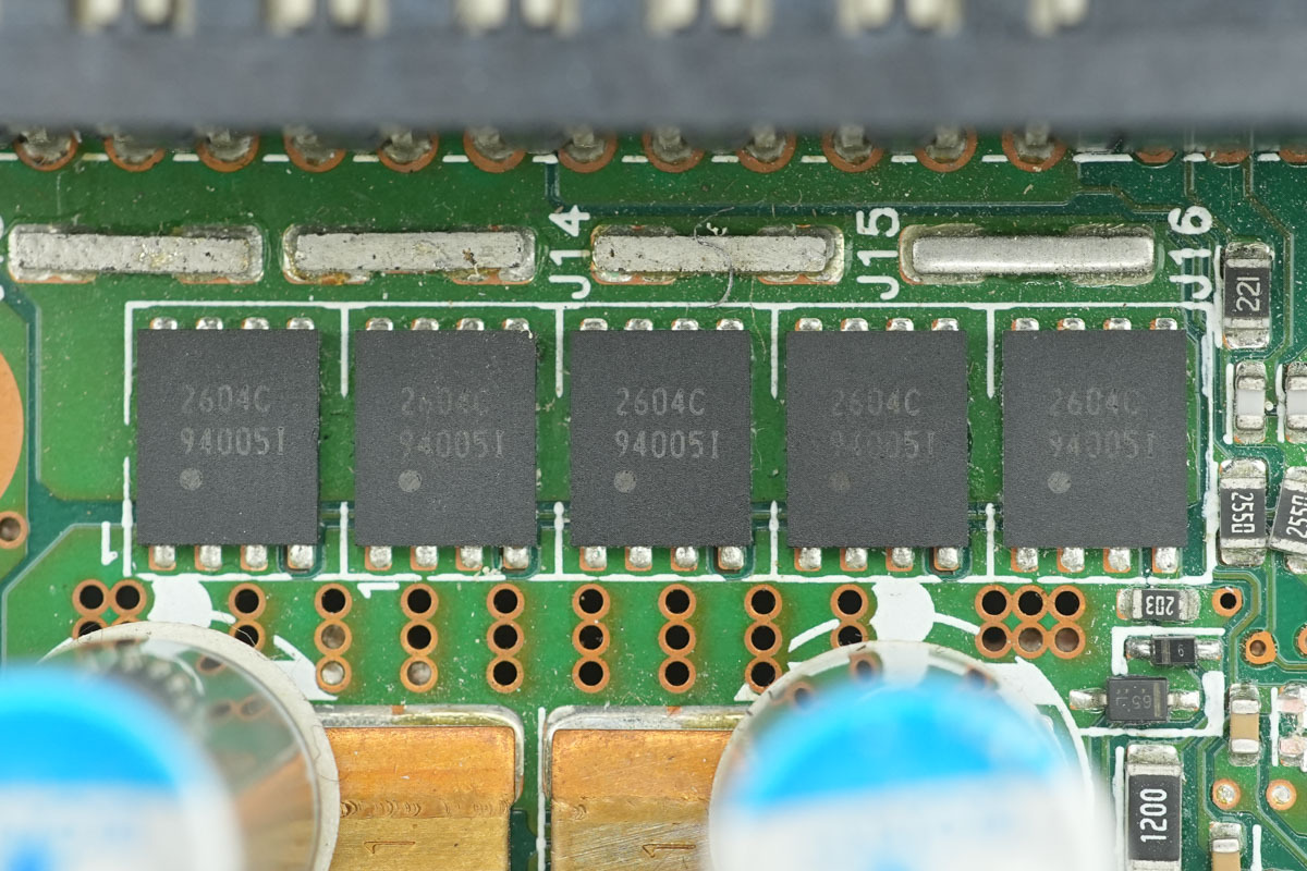
The output control MOSFETs are from APEC, marked 2604C, model AP2604CDT, NMOS, 25V and 0.65mΩ, and is housed in a PDFN5*6 package.
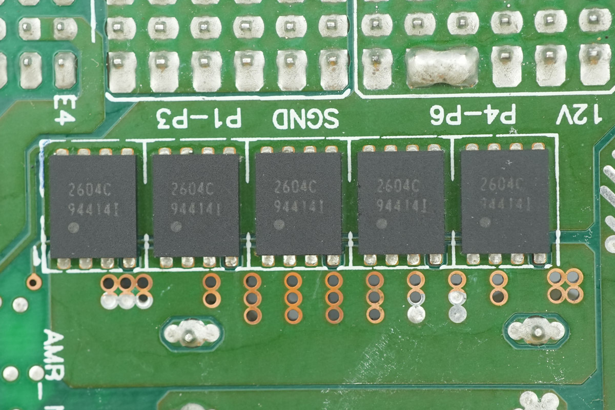
The back of the PCB features 5 output control MOSFETs of the same model.
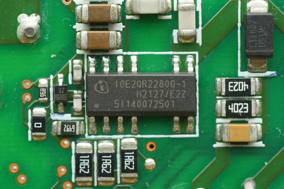
The standby power supply IC is from Infineon, model ICE2QR2280G-1. It integrates an 800V avalanche rugged MOSFET, supporting an output power of 30W under wide voltage inputs, and is housed in a DSO-12 package.
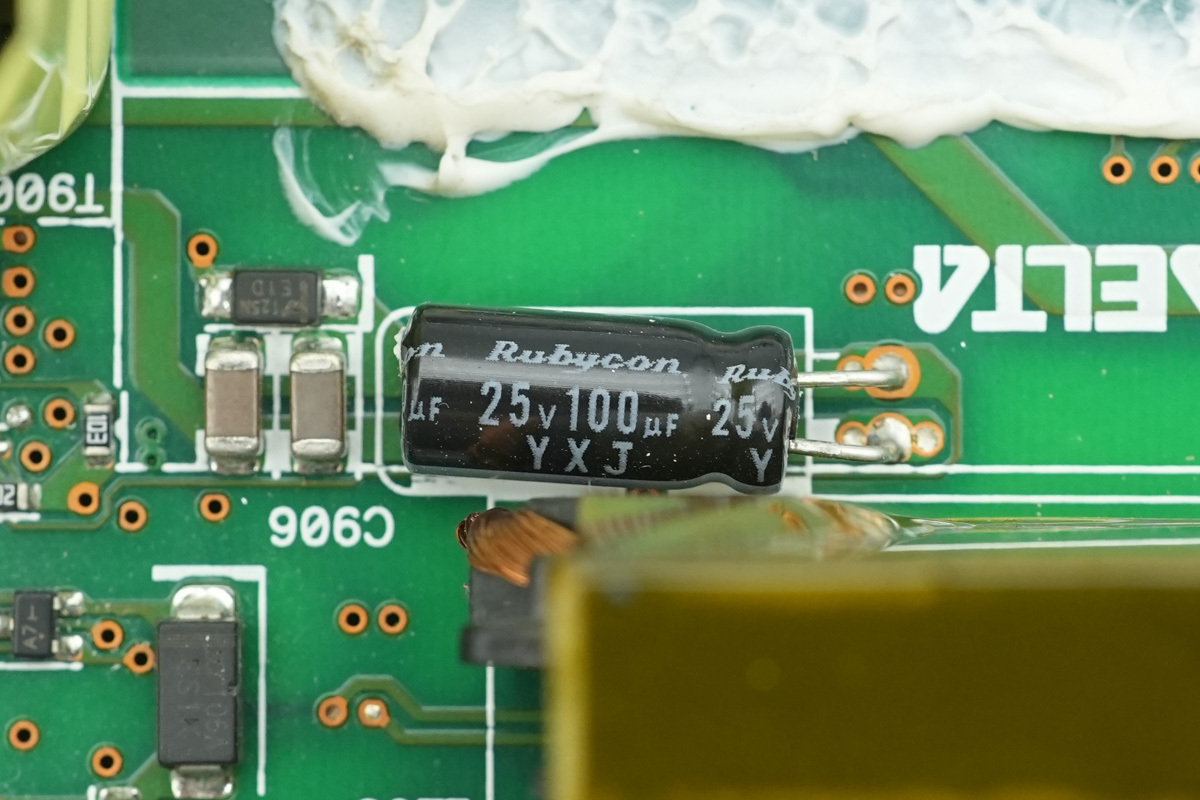
The filtering cap supplying power to the power IC is from Rubycon, belonging to the YXJ series of long-life electrolytic caps, spec 25V 100μF.
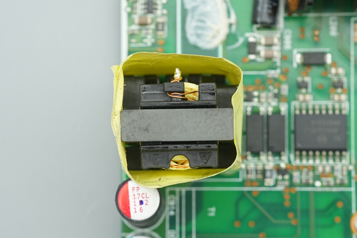
The standby power transformer is wrapped with insulating tape.
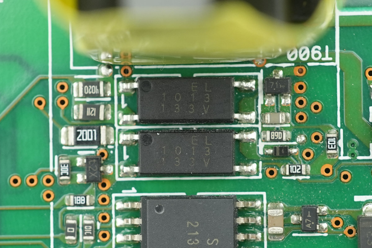
The optocouplers are utilized for output voltage feedback.
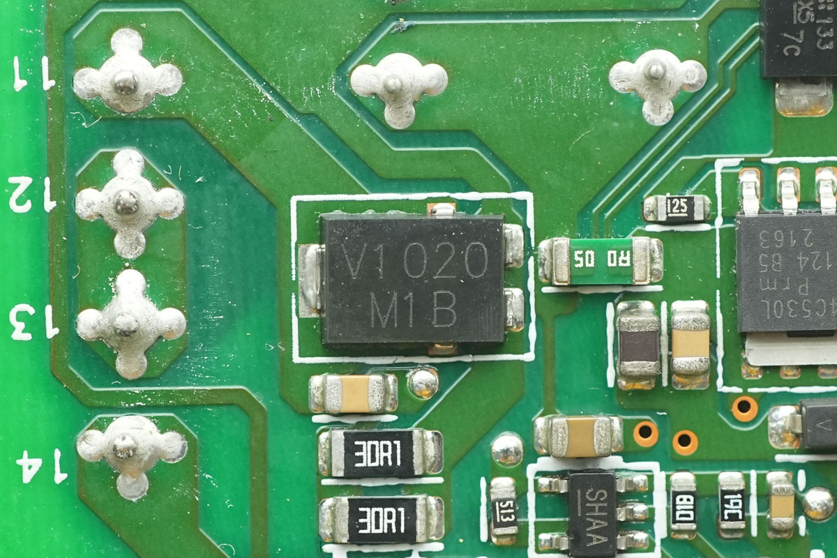
The standby power rectifier MOSFET is from VISHAY, marked V1020, model V10P20. It is a Trench MOS Barrier Schottky rectifier, spec 200V 10A, housed in a TO-277A package.
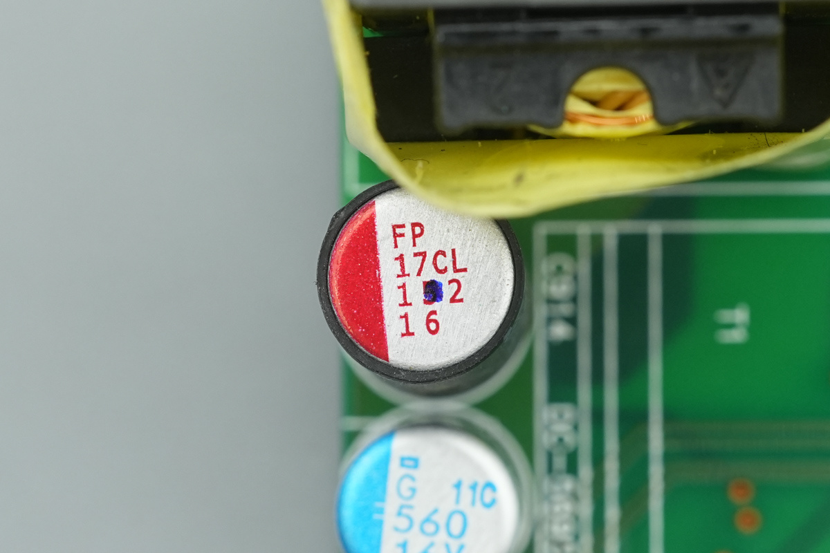
The filtering cap is from nichicon, spec 1500μF 16V.
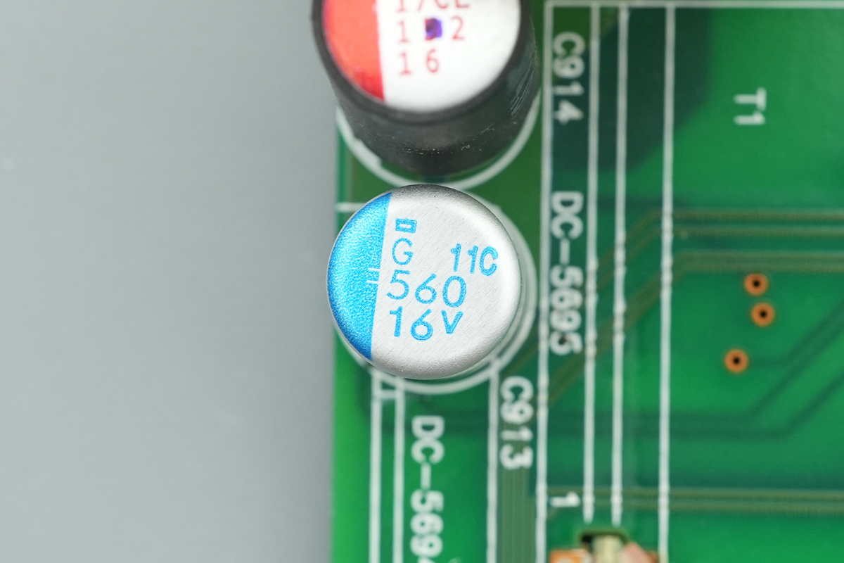
Another one is with the spec 560μF16V.
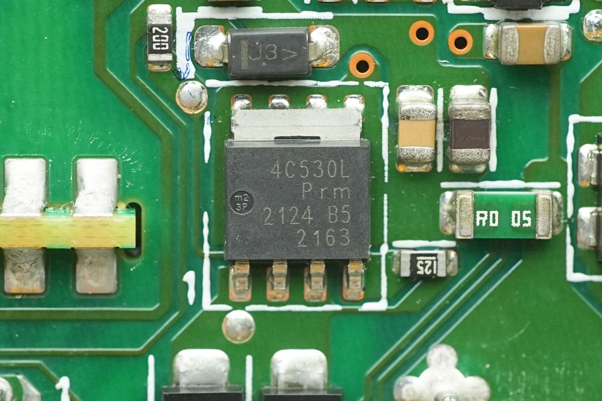
The power supply control MOSFET is from Nexperia, marked 4C530L, model PSMN4R5-30YLC, NMOS, 30V and 4.8mΩ, housed in an LFPAK package.
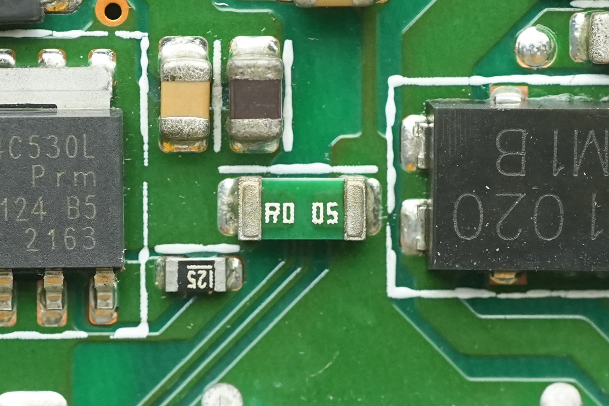
A 5mΩ current sense resistor.
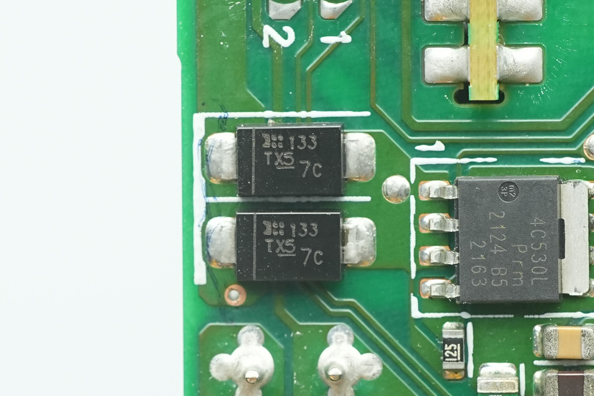
The Schottky diode is from DIODES, marked TX5, model SBRT5A50SA, 50V 5A, housed in an SMA package.
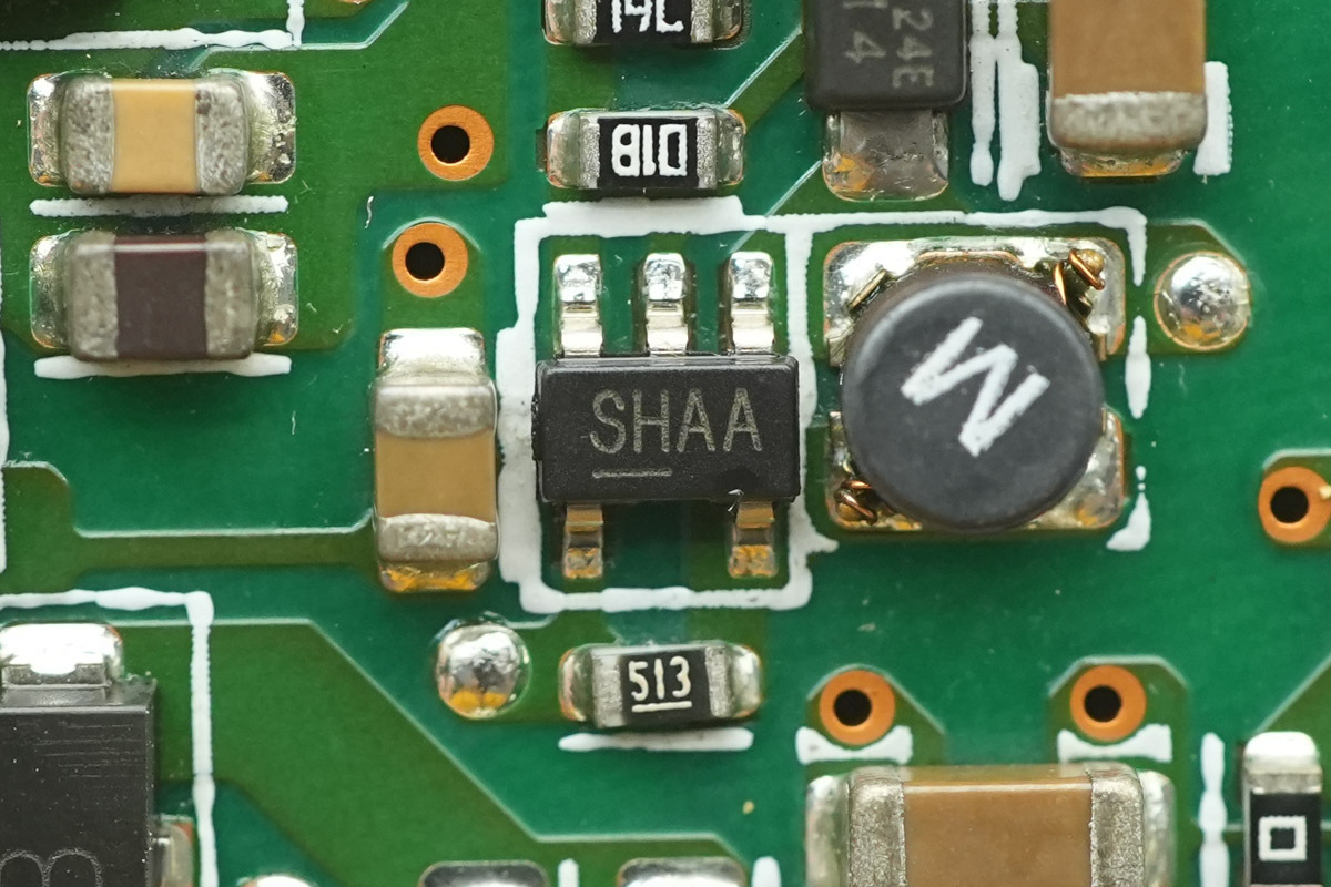
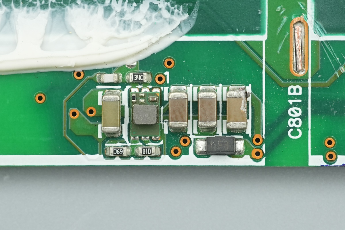
The step-up chip is from MICROCHIP, marked SHAA, model MIC2288. It supports an input voltage range of 2.5V to 10V, providing an output voltage up to 34V. It features a 1A switch current limit and a fixed 1.2MHz switching frequency, housed in a TSOT-23-5 package.
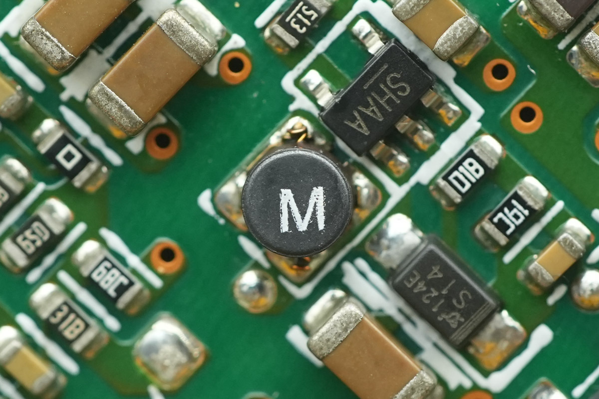
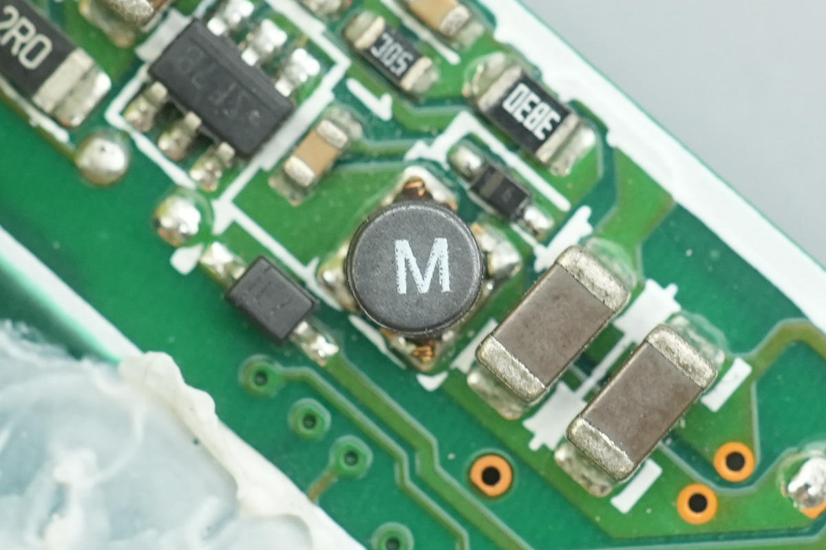
This is the matched SMD choke.
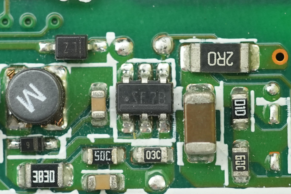
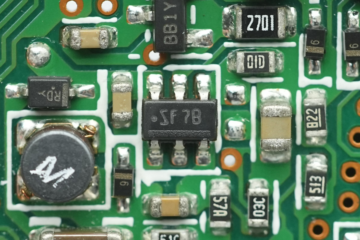
The step-down chip is from TI, marked SF7B, model LMR12010. It is a buck converter featuring an input voltage range of 3V to 20V and a 1A output current capability, housed in an SOT-23 package.
This is the matched SMD choke.
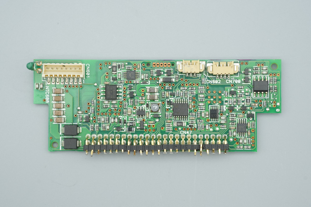
Here is the power conversion module.
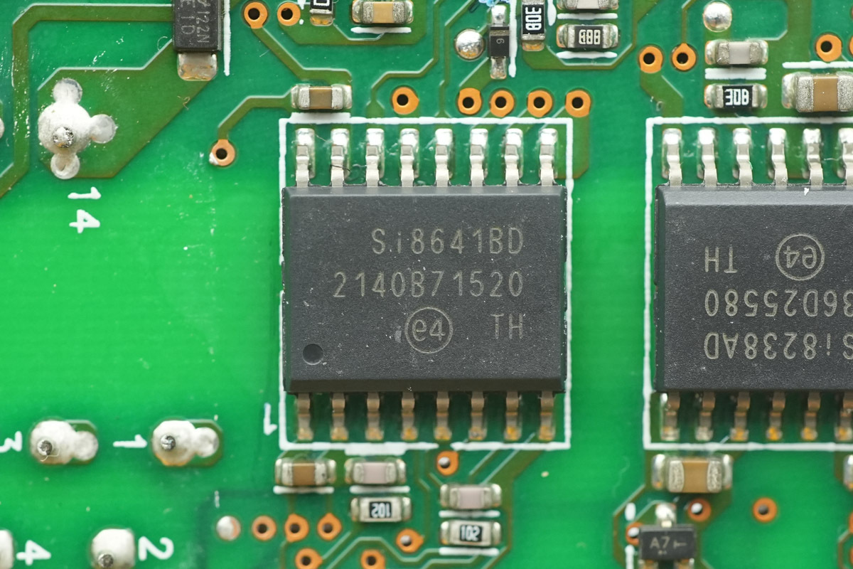
The isolated driver IC is from SKYWORKS, model Si8641BD. It features a configuration of three forward channels and one reverse channel, supporting a data rate of up to 150Mbps. It provides a robust 5kVrms withstand isolation rating and is housed in a wide-body SOIC-16 package.
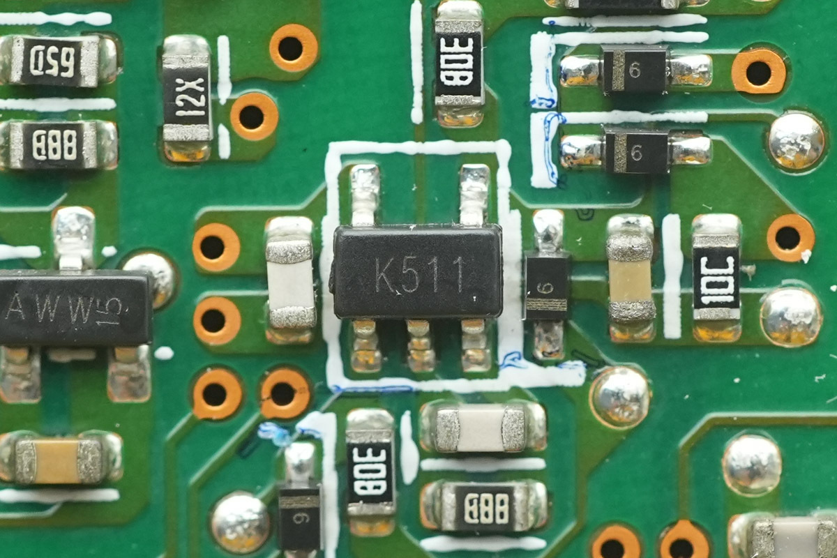
The voltage comparator is from ST, marked K511, model TS391ILT. It is a low-power single voltage comparator, housed in an SOT-23-5 package.
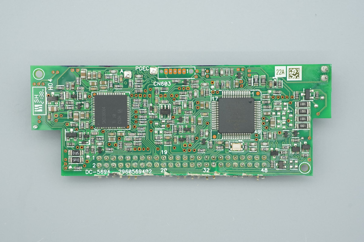
An LLC controller and an MCU are positioned on the outer side of the control PCB.
The other side contains a memory, operational amplifier, voltage comparator, and AND gate chip.
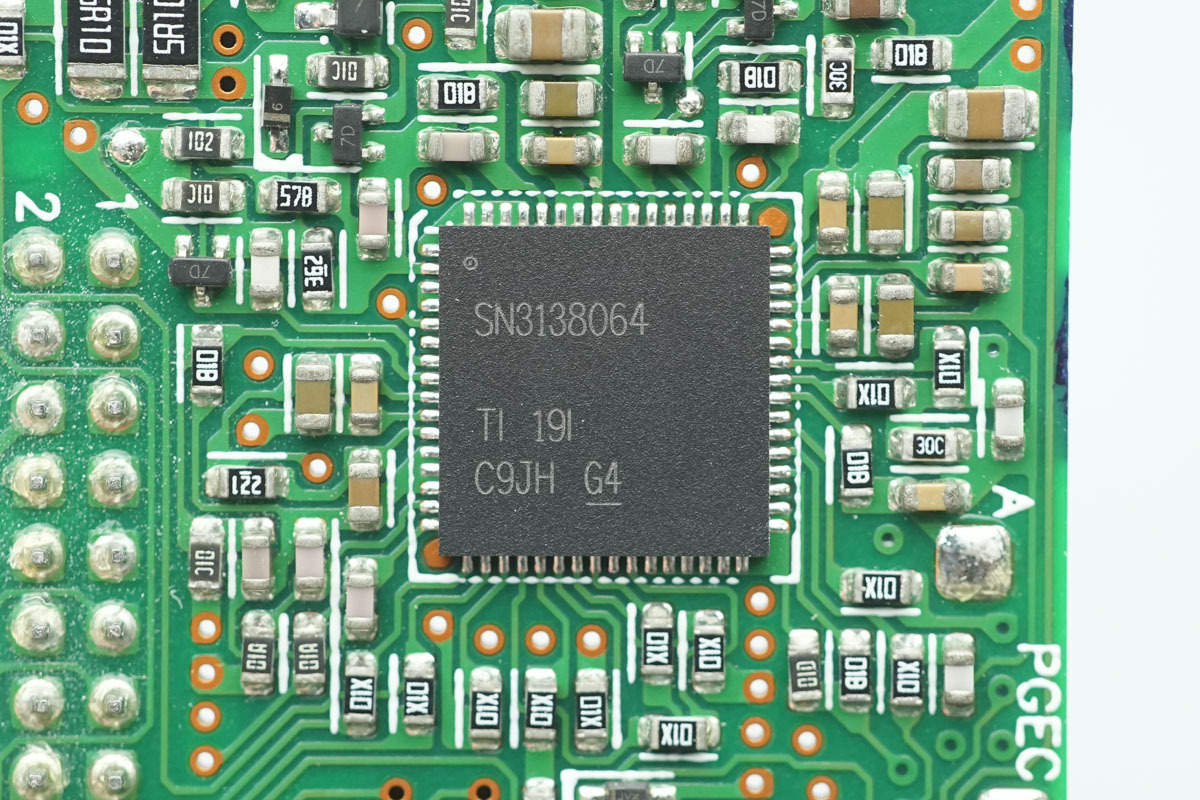
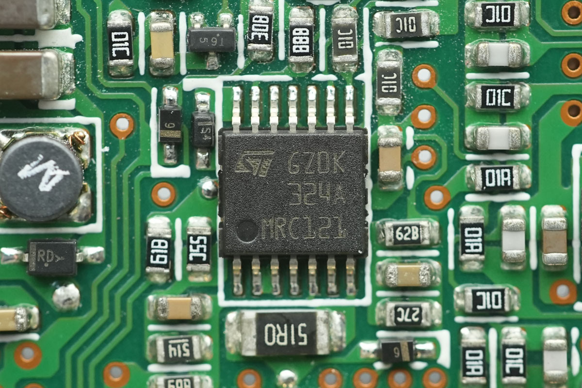
The LLC controller is from TI, marked SN3138064, and is packaged in a VQFN64 package.
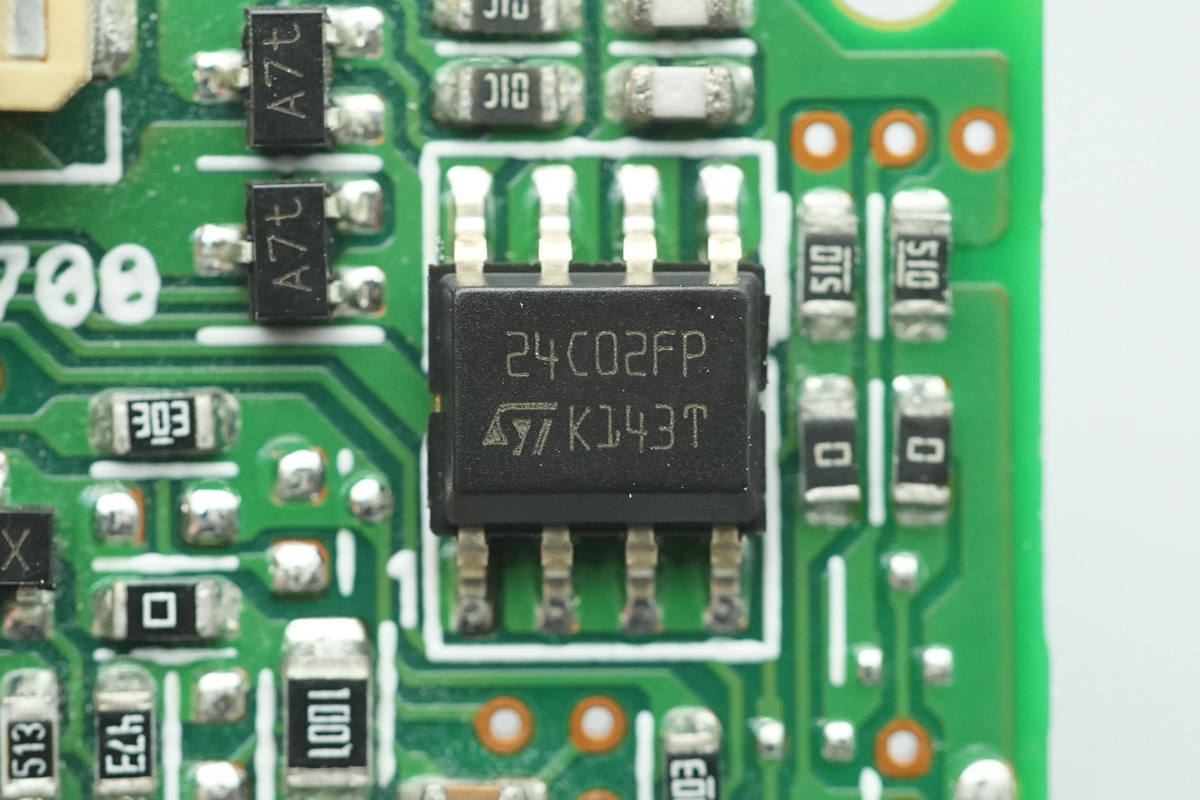
The memory is from ST, model M24C02-F, with a capacity of 256B, supports an operating voltage range of 1.7-5.5V, and is packaged in an SO8 package.
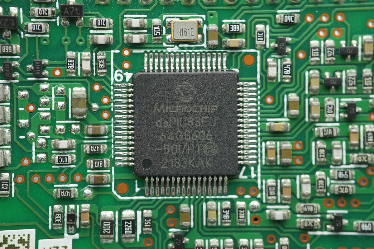
The MCU is from MICROCHIP, model dsPIC33FJ64GS606, which is the same model as the PFC controller.
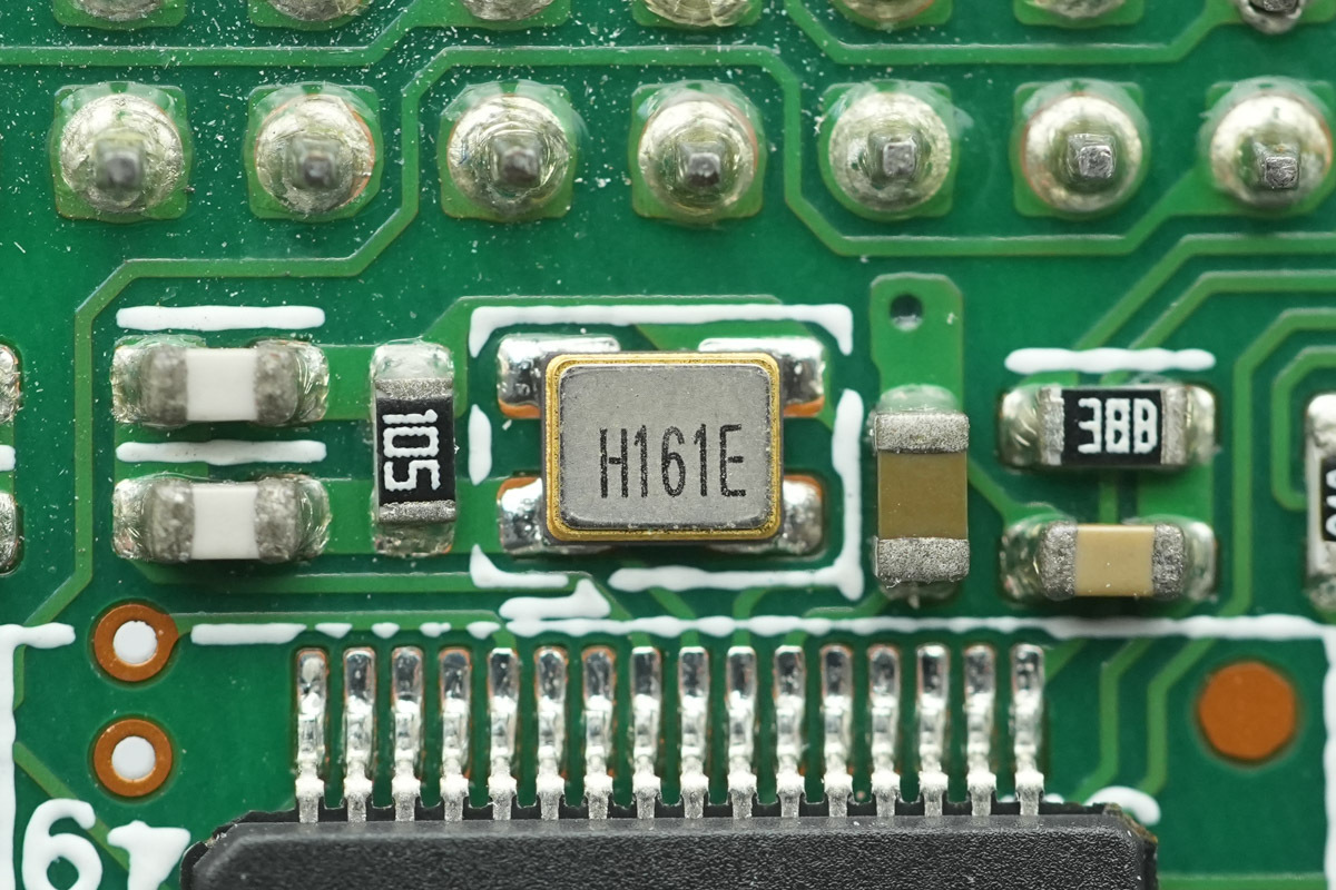
This is the external clock crystal oscillator for the MCU.
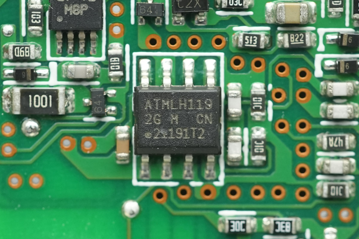
The memory is from MICROCHIP, marked 2G, model AT24CM01, with a capacity of 128KB, supports 1.7-5.5V operating voltage, and uses an 8-lead SOIC package.
The operational amplifier is from ST, model LM324A, a low-power, low-input-bias-current quad op-amp in a TSSOP14 package.
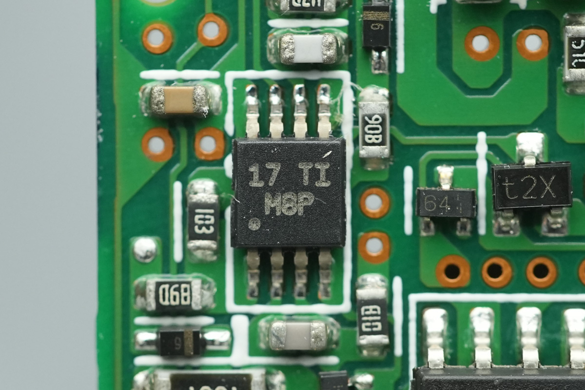
The voltage comparator is from TI, marked M8P, model LM393A. It is a dual-channel precision differential comparator in a VSSOP8 package.
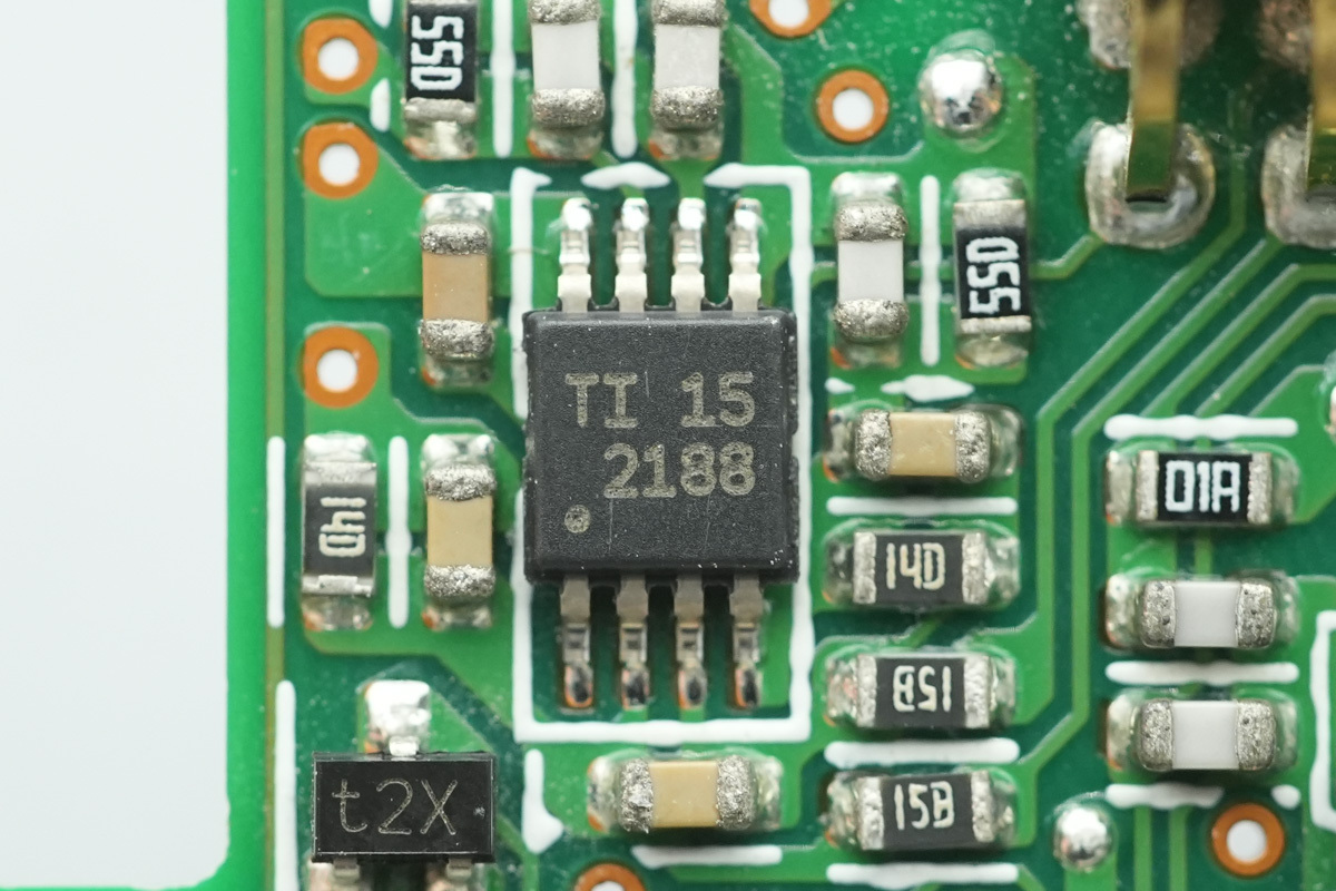
The operational amplifier is from TI, model OPA2188. It is a low-noise, rail-to-rail output, 36V zero-drift operational amplifier, housed in a VSSOP-8 package.
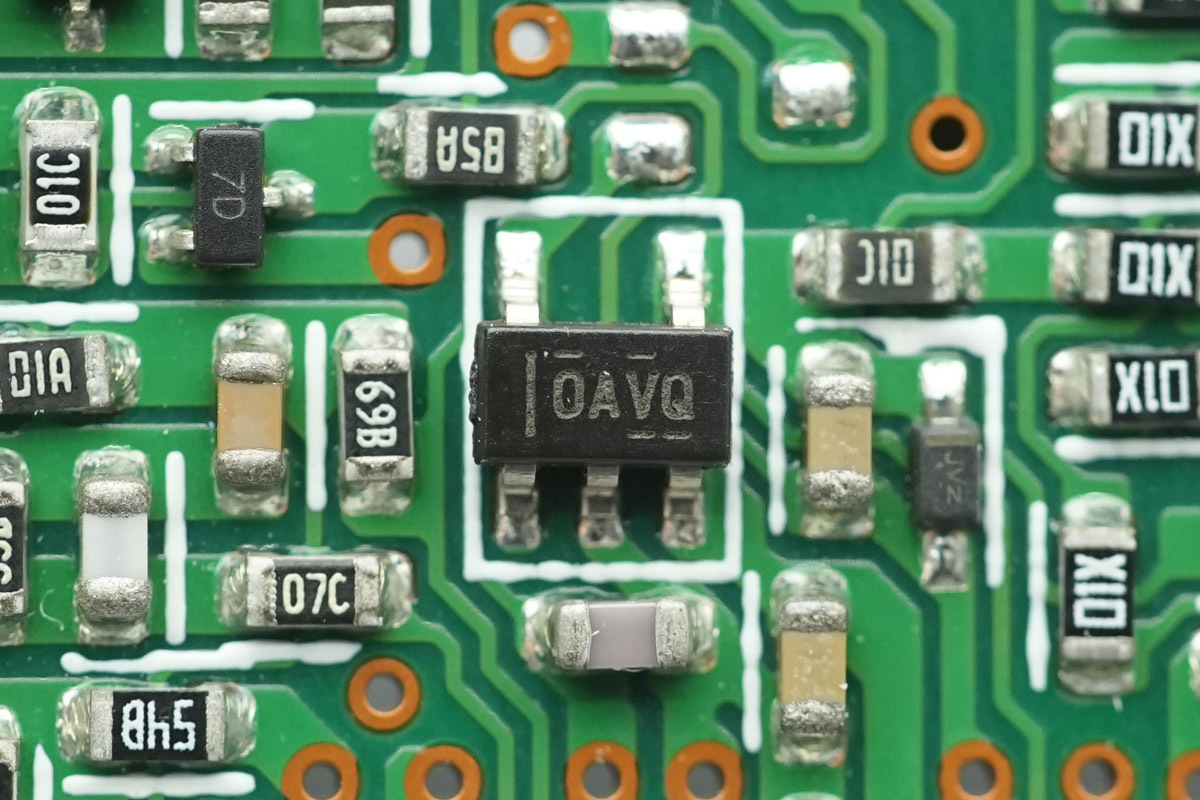
The operational amplifier is from TI, marked OAVQ, model OPA365. It is a precision, rail-to-rail operational amplifier, housed in an SOT-23 package.
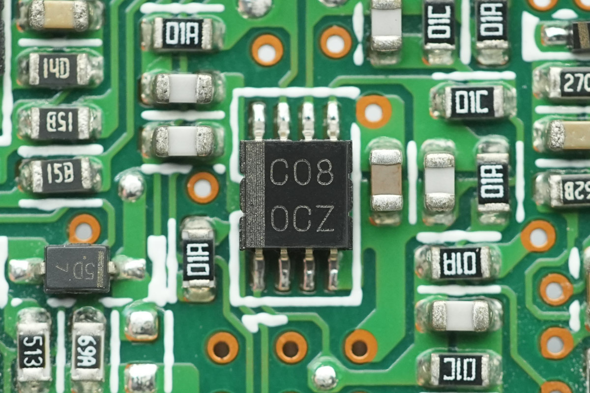
The AND gate chip is from TI, marked C08, model SN74LVC2G08. It is a dual 2-input positive-AND gate supporting a wide operating voltage range from 1.65V to 5.5V, housed in a VSSOP-8 package.
The step-down chip is from TI, model LMR12010.
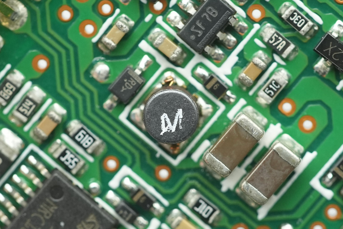
Here is the matched SMD choke.
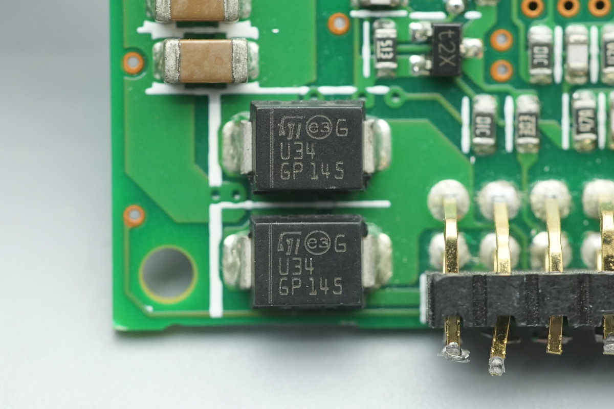
The Schottky diode is from ST, marked U34, model STPS340U, spec 40V 3A, housed in a SMB package.
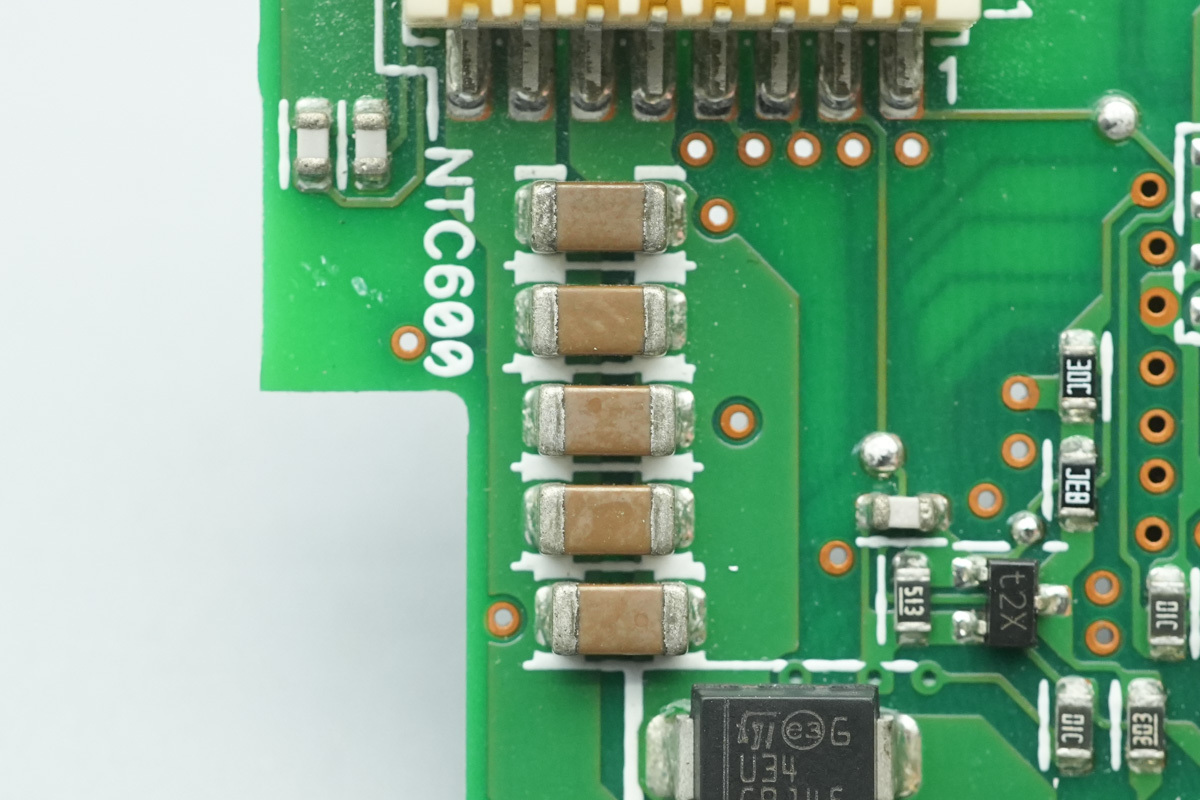
Here are the MLCCs connected in parallel.
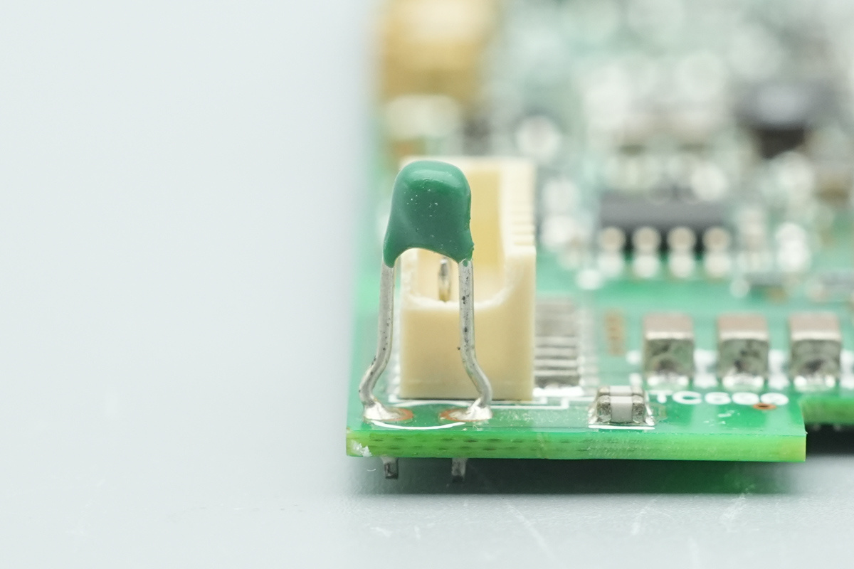
A NTC thermistor utilized for internal thermal monitoring of the power supply.
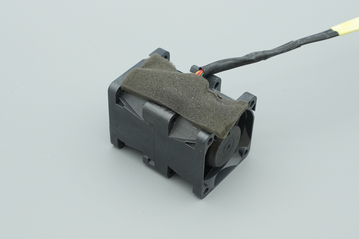
This is the cooling fan, featuring shock-absorbing foam tape applied along the edges.

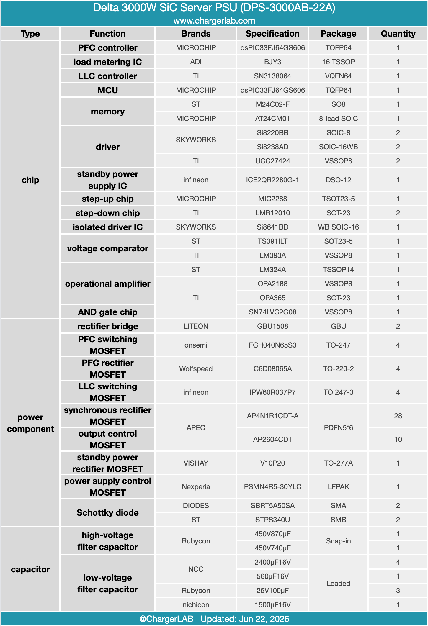
Well, those are all components of the Delta 3000W SiC Server PSU (DPS-3000AB-22A).
Summary of ChargerLAB
Delta’s 3000W SiC Server Power Supply (Model: DPS-3000AB-22A) is engineered to meet ultra-high-density data center demands. It accepts wide-range AC inputs (100-127V / 200-240V) to deliver a massive 12V main rail at 250A, plus a 5V/3A standby rail, yielding a steady 3000W of power. Thermal management is optimized via an integrated fan that pulls air from the AC inlet and exhausts through the rear connector.
Teardown reveals a premium internal layout utilizing a two PCBs interconnect connected by heavy-duty soldered wires. The architecture integrates a cutting-edge bidirectional switch PFC, full-bridge LLC, and synchronous rectification design. MICROCHIP's dsPIC33FJ64GS606 MCU drives the PFC stage alongside SKYWORKS Si8220BB drivers and best-in-class onsemi FCH040N65S3 MOSFETs paired with Wolfspeed C6D08065A SiC diodes.
Resonant conversion relies on TI's SN3138064 LLC controller driving low-loss Infineon IPW60R037P7 switches via SKYWORKS Si8238AD isolation drivers. Synchronous rectification features APEC AP4N1R1CDT-A MOSFETs steered by TI UCC27424 drivers, while an Infineon ICE2QR2280G-1 powers the standby rail. Packed with Japanese caps and comprehensively ruggedized with structural adhesive, this power supply guarantees enterprise-grade reliability and top-tier efficiency.
Related Articles:
1. Teardown of Delta 550W SiC Server Power Supply (DPS-550AB-2)
2. Review of Delta's World's First PD3.1 240W USB-C Power Adapter
3. Delta PD3.1 240W USB-C Power Adapter: High-Efficiency Charging Solution for High-Performance Devices