Introduction
We obtained the Infypower REG1K0135A2 new energy vehicle charging module. The unit features a metal enclosure assembled with screws and a front-mounted information label. It operates with a three-phase AC input, supporting an input voltage range of 260–530 V, and delivers a DC output voltage of 150–1000 V with an output current of 133 A. The rated output power is 40 kW, making it suitable for 800 V platform electric vehicles.
The Infypower charging module adopts a new circuit topology and a full SiC design, achieving a comprehensive conversion efficiency of over 96% and a peak efficiency exceeding 97%. It features a patented power transistor heatsink integration design and uses potting for enhanced durability, providing much higher reliability than traditional air-cooled solutions. The following is a teardown of this Infypower EV charging module to examine its internal design and component selection.
Product Appearance
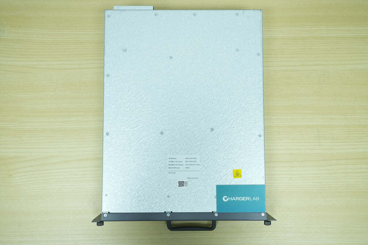
The module features a metal enclosure. The PCBA module is secured in place with mounting posts.
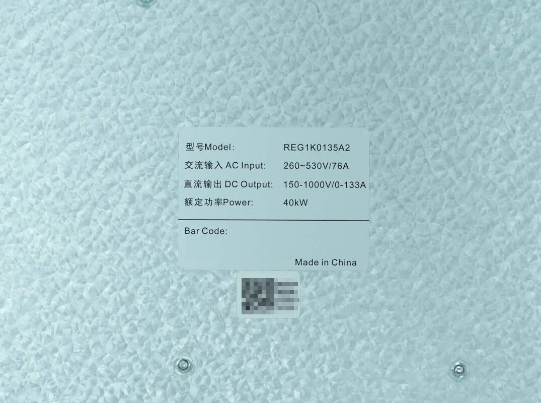
Model: REG1K0135A2
AC Input: 260–530 V / 76 A
DC Output: 150–1000 V / 0–133 A
Rated Power: 40 kW
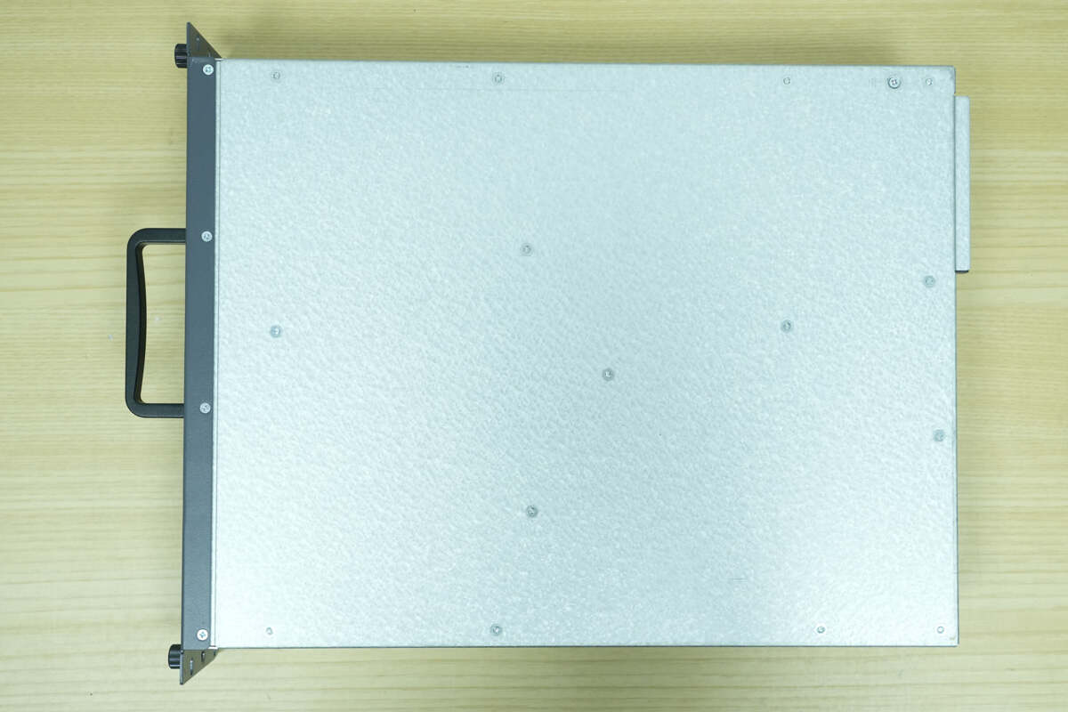
Screw mounting posts are also provided on the back side to secure the PCBA module.
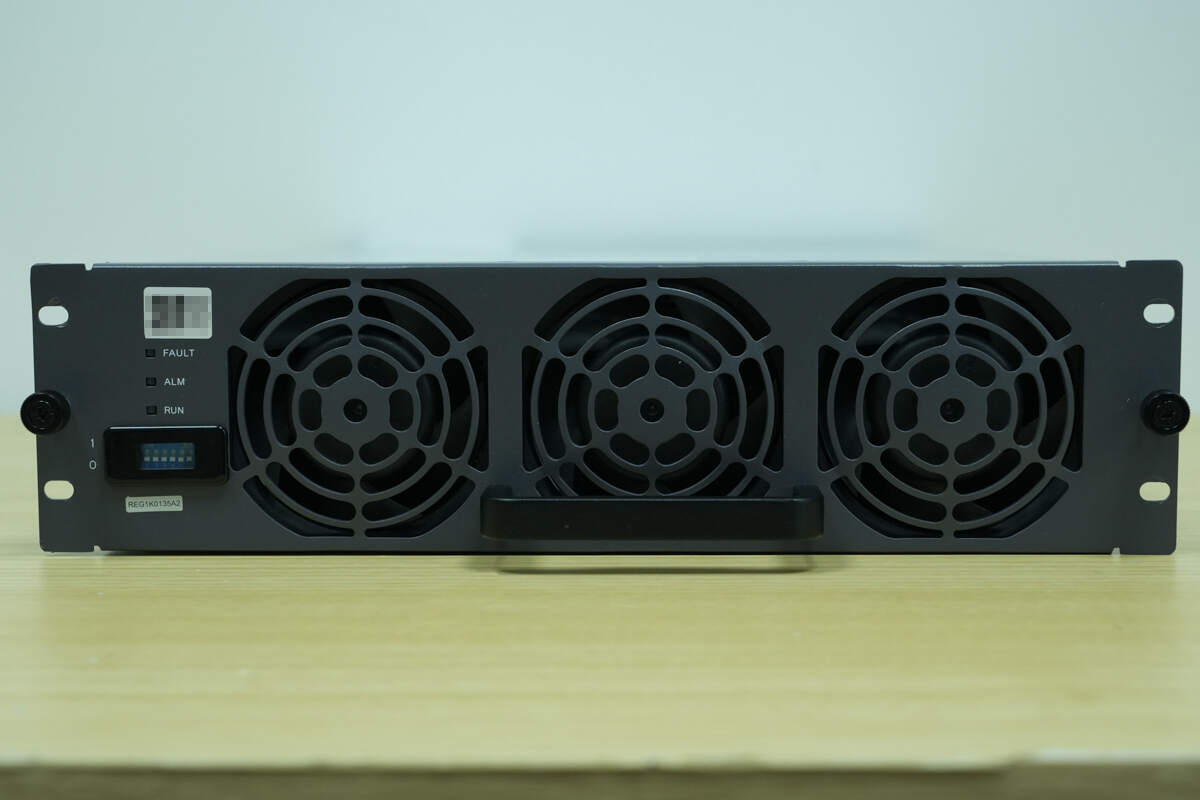
There are screws on both sides of the front panel. The left side features LED indicators and a DIP switch, while the center area includes a handle and cooling fans.

The sides are secured with screws.

The rear side features an AC input connector and a DC output connector.

The AC input connector has a four-pin design and includes reverse-polarity protection.
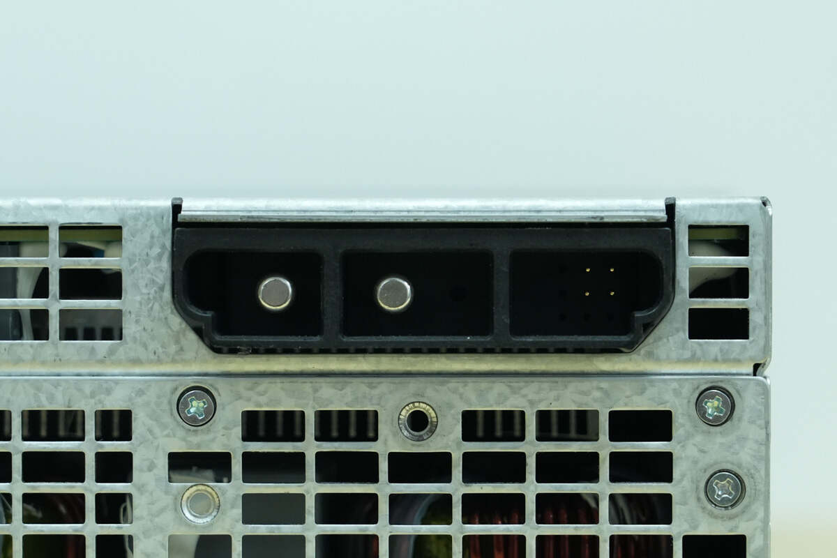
Close-up of the DC output connector and the CAN communication interface.
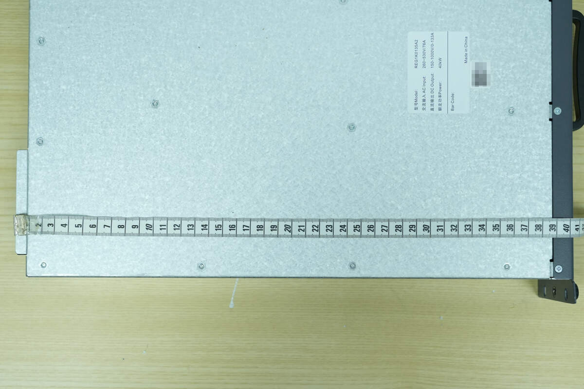
The length of the module is about 403 mm (15.87 inches).
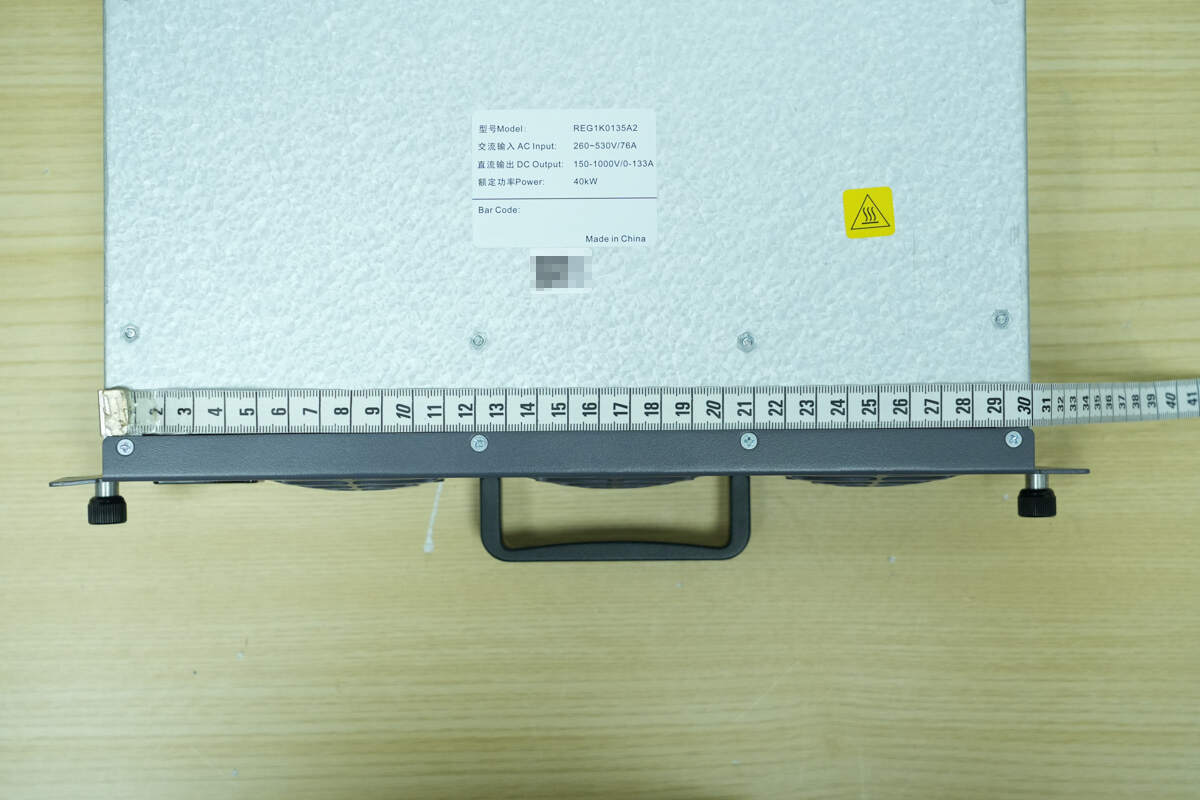
The width is about 298 mm (11.73 inches).
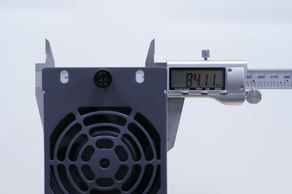
The thickness is about 84.1 mm (3.31 inches).
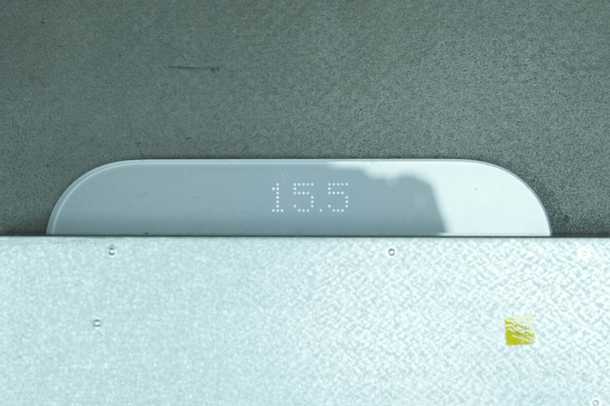
The weight is about 15.5 kg (34.17 pounds).
Teardown
Next, let's take it apart to see its internal components and structure.

Unscrew the screws of the front panel and sides. The PCBA module is connected via wires.
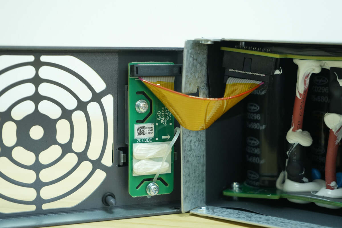
The PCB for the LED indicators and the DIP switch is connected via a ribbon cable.
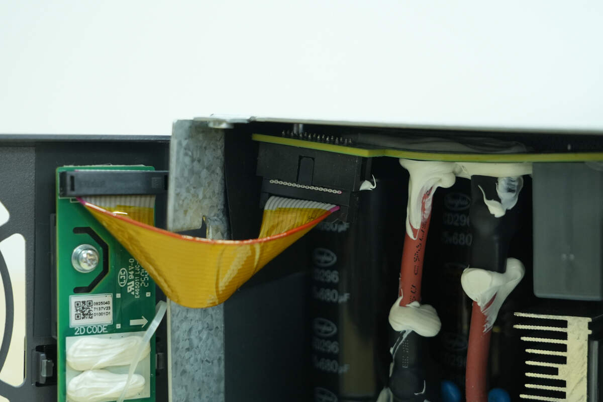
The ribbon cable is connected via a connector and wrapped with high-temperature tape.
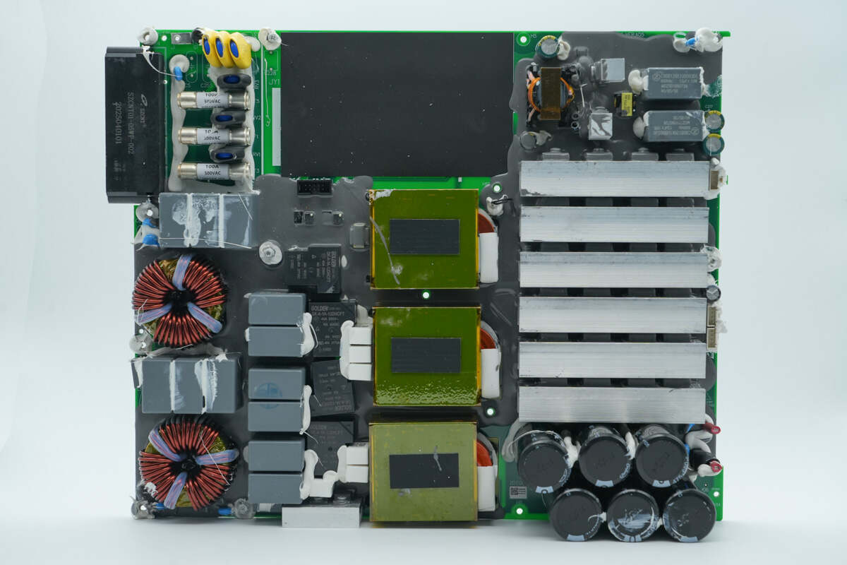
The front side of the PFC module features fuses, varistors, safety X2 capacitors, common mode chokes, relays, startup resistors, and PFC boost inductors. The heatsinks on the right dissipate heat from the PFC MOSFETs and rectifiers. Below the heatsinks are high-voltage filter capacitors.
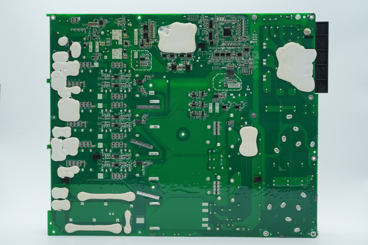
The rear side includes the PFC controller, operational amplifiers, regulator chips, isolation chips, and drivers.
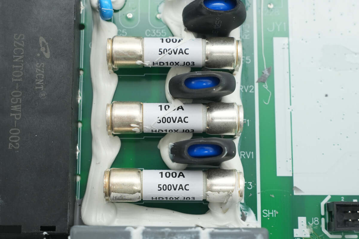
The three input fuses are each rated at 100 A, 500 VAC.
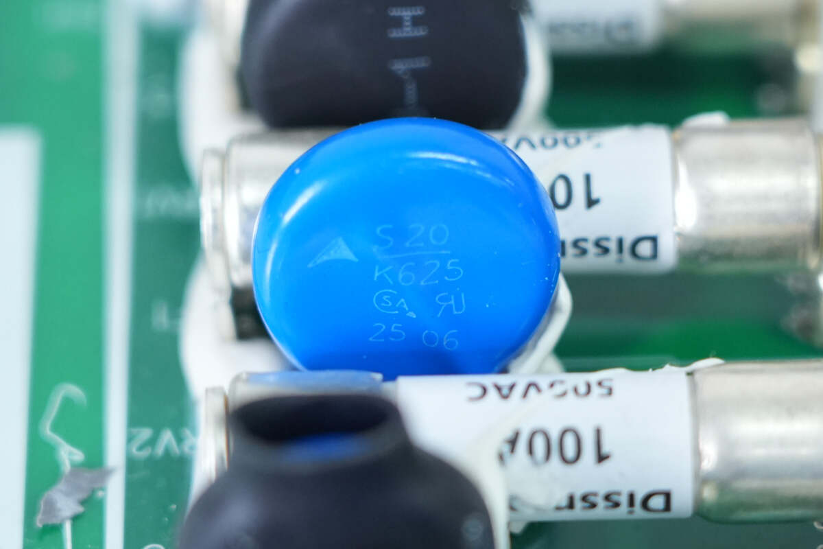
The varistor is supplied by TDK and is marked with S20K425.

The varistors are supplied by TDK and are marked with S20K460K1.
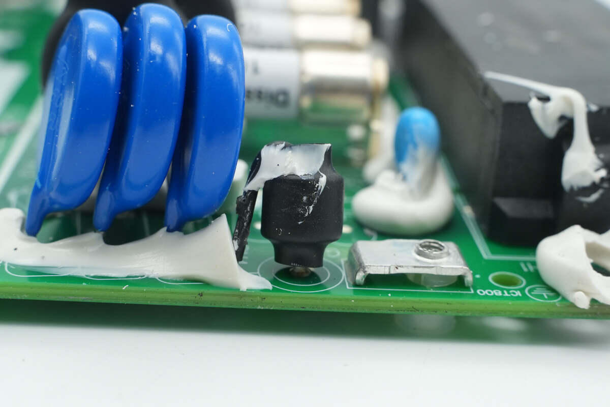
The gas discharge tube is insulated with heat-shrink tubing.

The blue Y capacitor is from SHM.
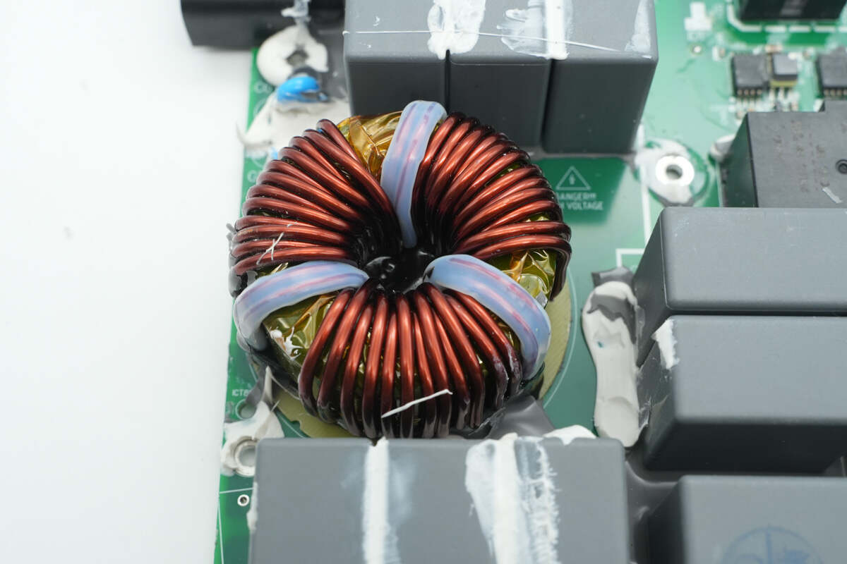
The common mode choke is wound with enameled wire, and a bakelite insulating plate is placed at the bottom.

The other common mode choke features the same design.
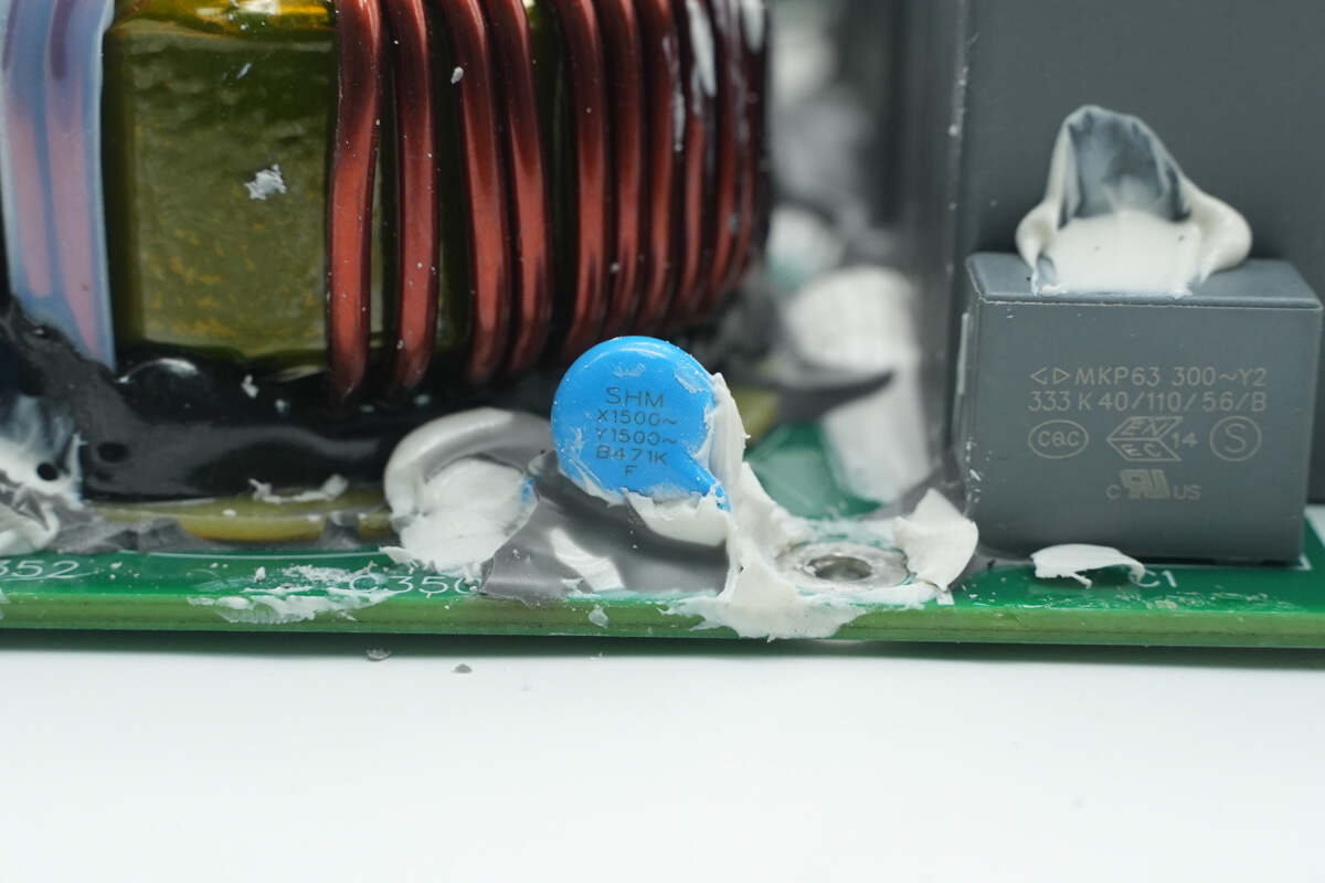
The blue Y capacitor is also from SHM.
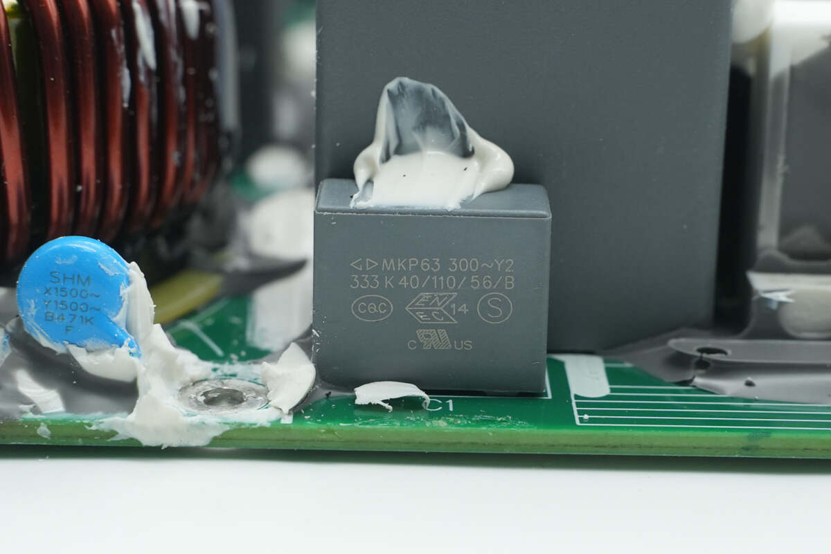
The film Y capacitor is manufactured by Faratronic.
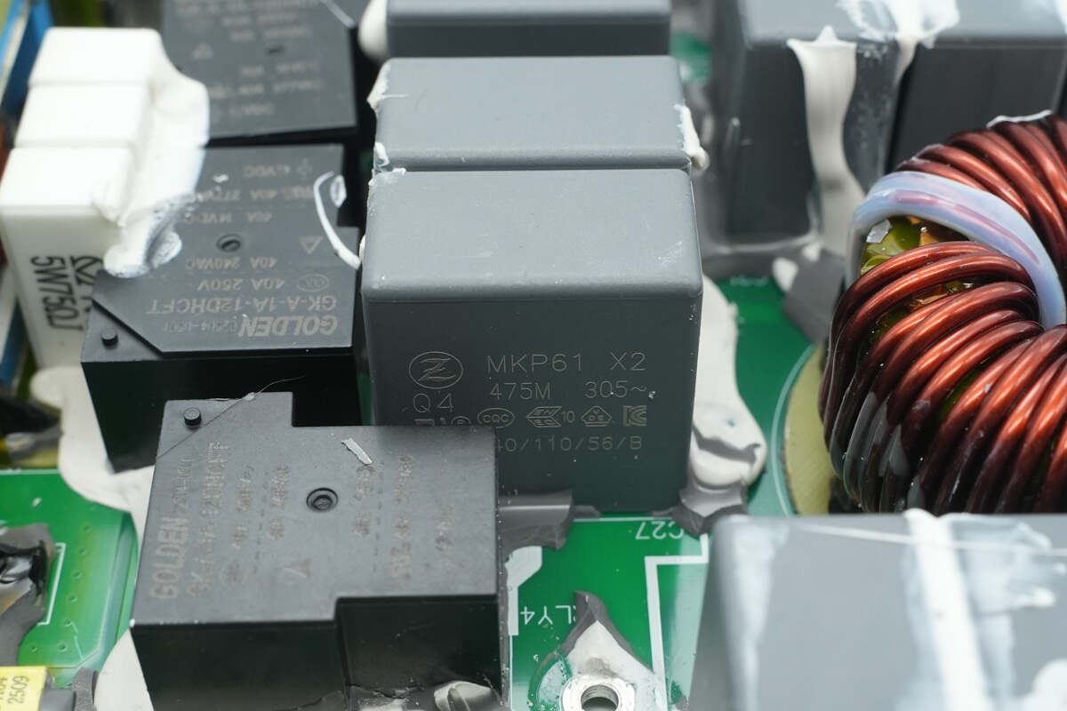
The safety X2 capacitor is from Zhongxing and has a specification of 4.7 μF.
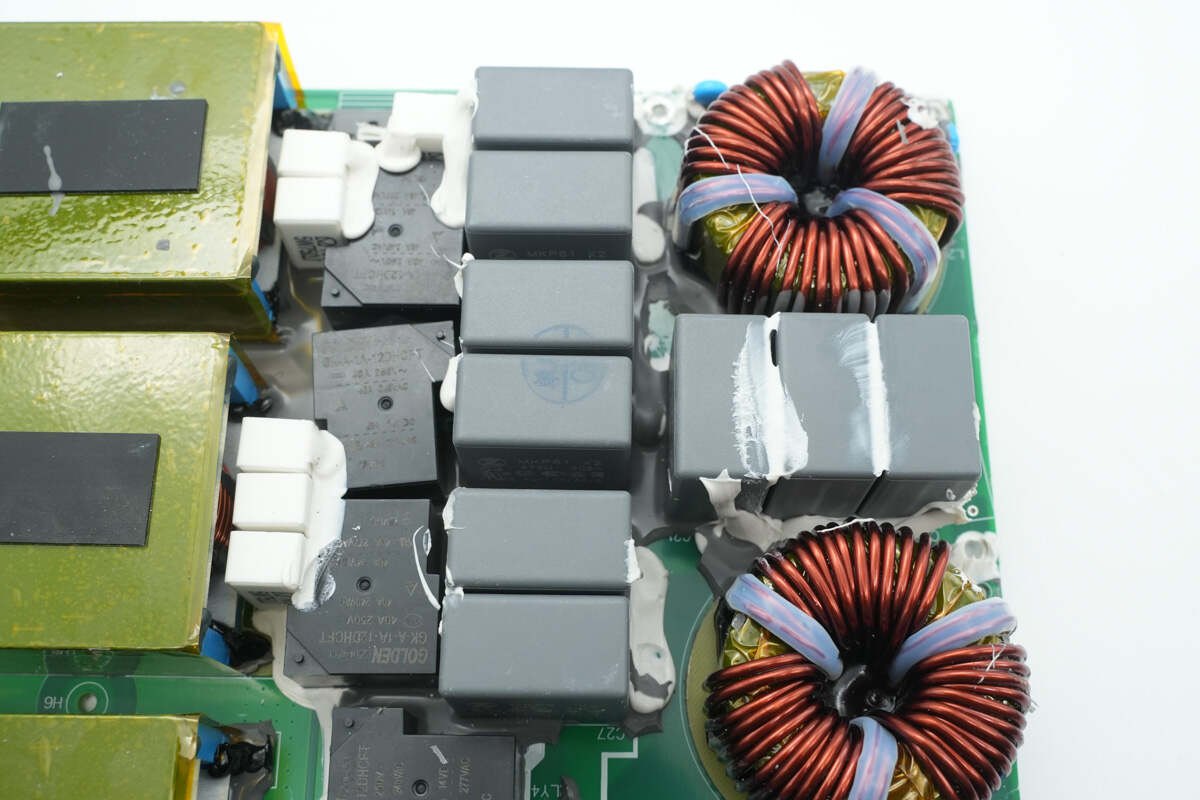
There are a total of nine safety X2 capacitors, all with the same specification.

Close-up of the four soft-start relays and six soft-start resistors.
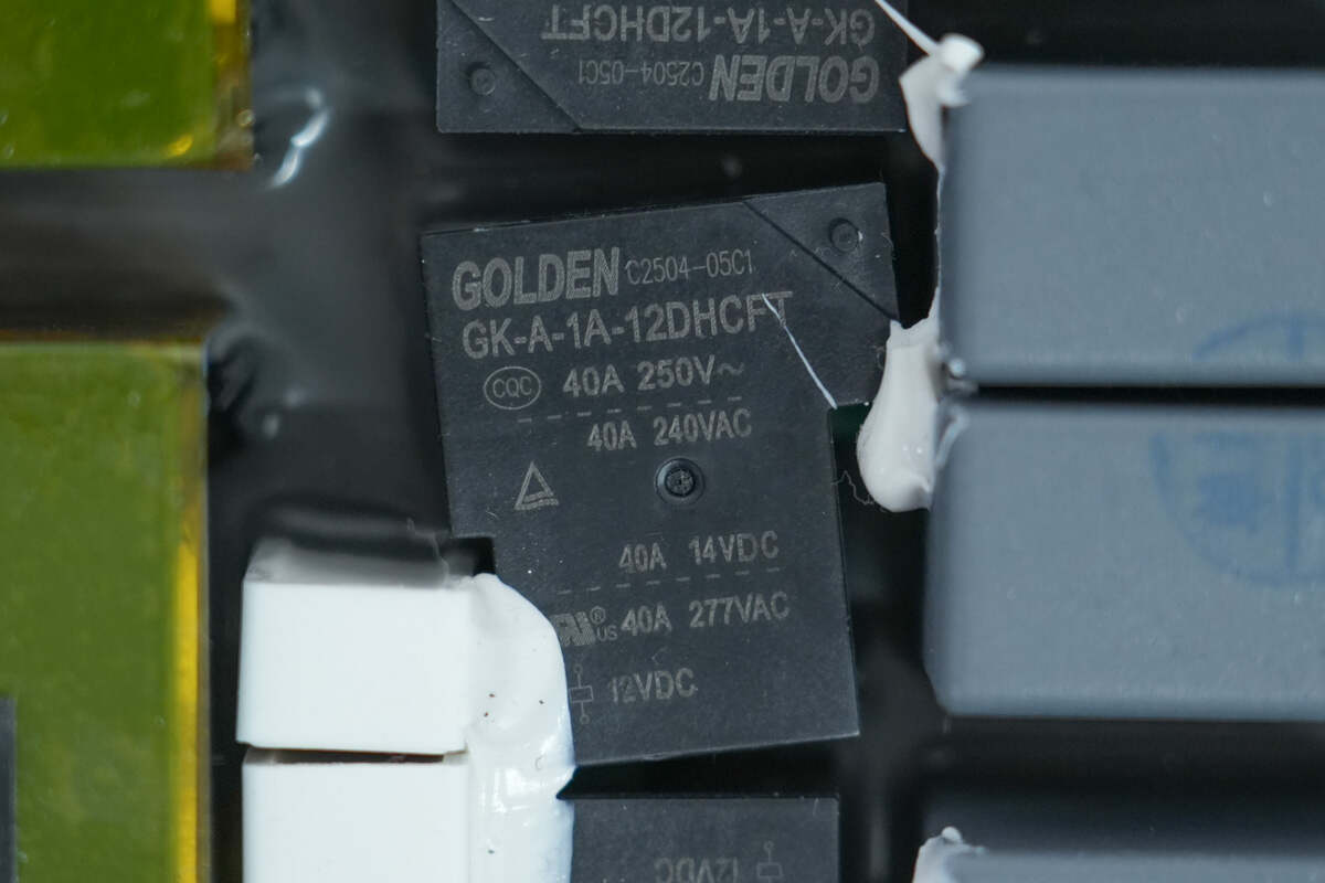
The soft-start relays are supplied by GOLDEN, model GK-A-1A-12DHCFT. Each relay contains a single normally open contact with a contact rating of 40 A, 250 V, and a coil voltage of 12 V.
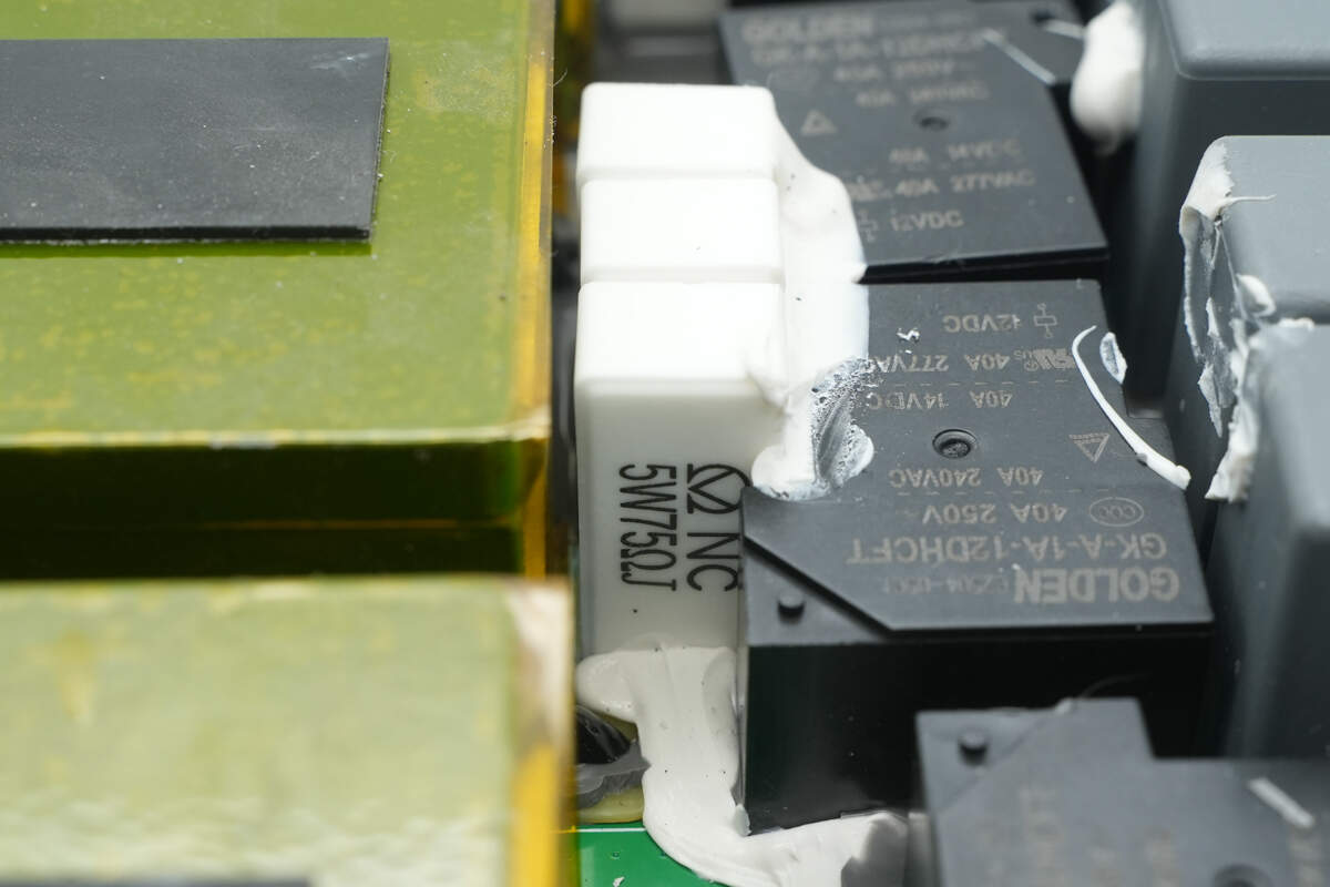
The soft-start resistors are supplied by Yongxing, each rated at 5 W, 75 Ω, with three resistors connected in series.
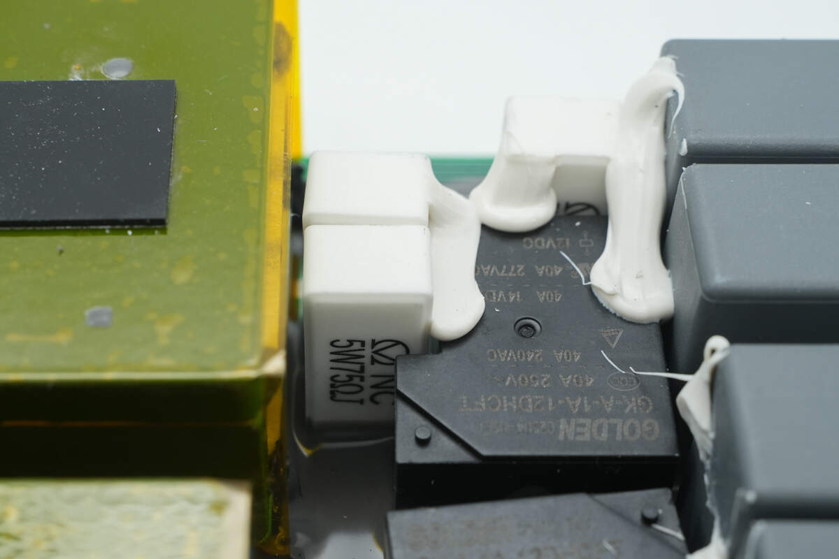
The other set of startup resistors has the same specifications.
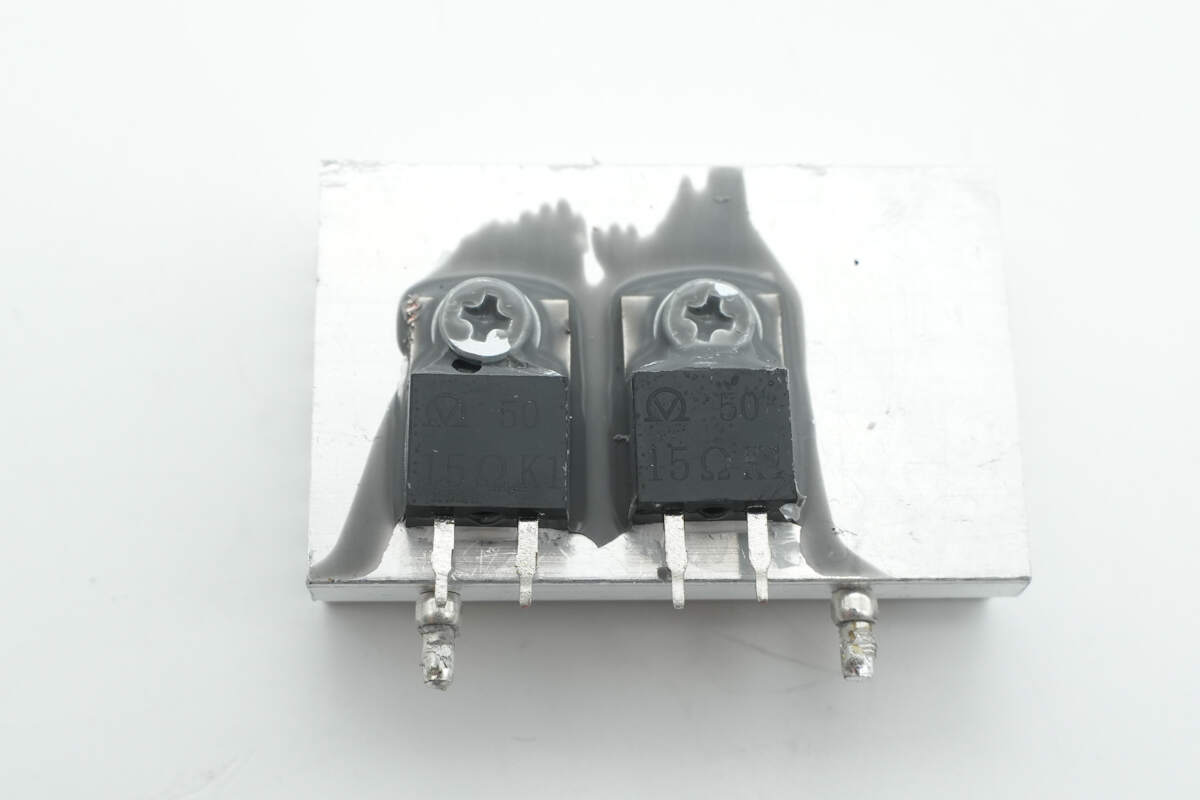
These two resistors are supplied by Yongxing. They are RMG10 power-type encapsulated resistors, each rated at 15 Ω and housed in a TO-220 package.
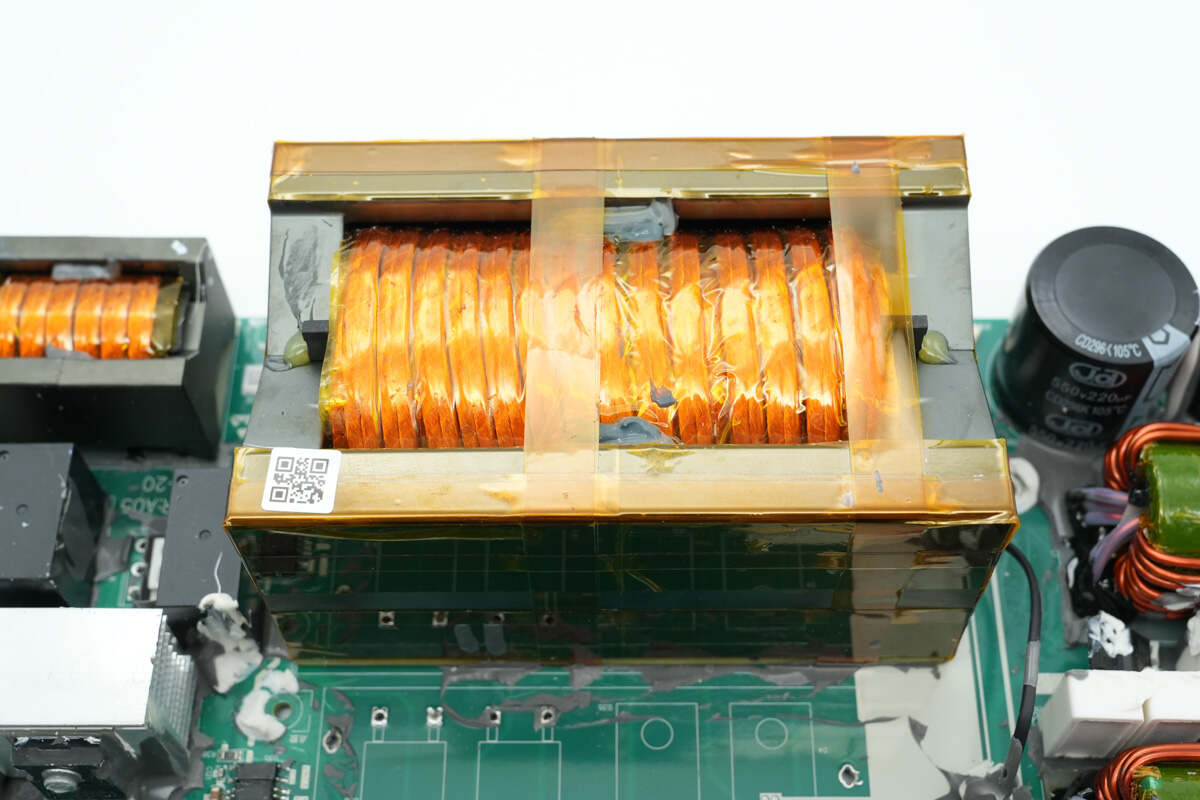
Close-up of the three PFC boost inductors.
The PFC boost inductors are wound with flat copper wire, and the magnetic cores are insulated with tape. A thermistor is mounted on the heatsink on the left to monitor temperature.
Film capacitors are installed on the side of this PFC boost inductor.

Four 3 mΩ sense resistors are used for inductor current detection.

Close-up of the other set of sense resistors.
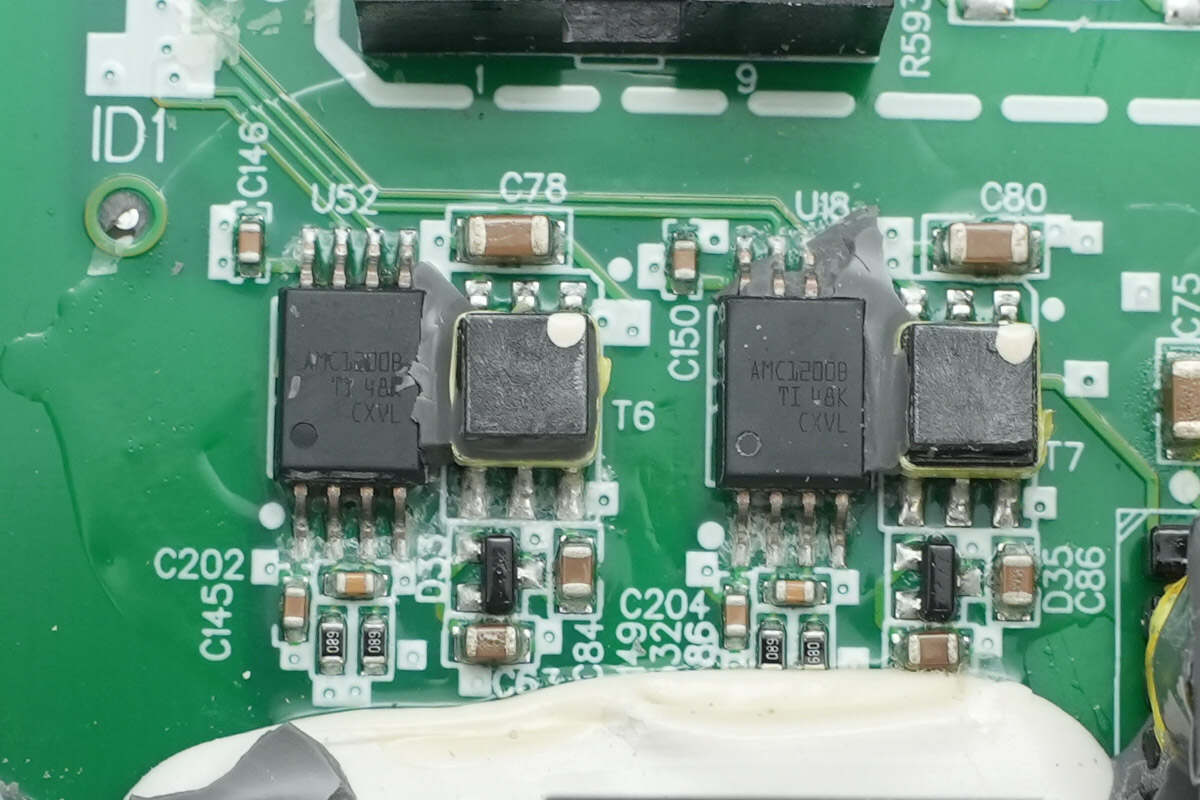
The isolation chips used for current sensing are supplied by TI, model AMC1200B. They are high-precision isolated amplifiers in an SOIC-8 package.

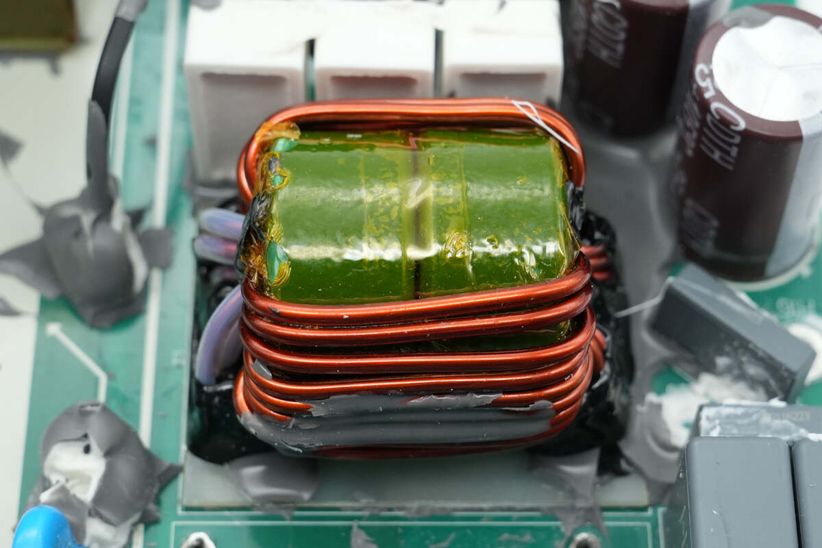
Close-up of the isolated transformer used for the power supply.

The PFC MOSFETs and rectifiers are mounted on the heatsink.
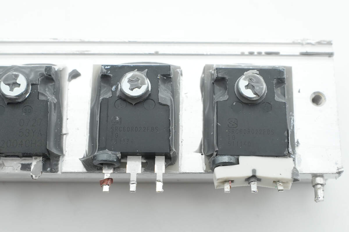
The PFC MOSFETs are from Sanrise, model SRC60R022FBS. They are NMOS devices with a voltage rating of 600 V and an on-resistance of 22 mΩ, housed in a TO-247 package.
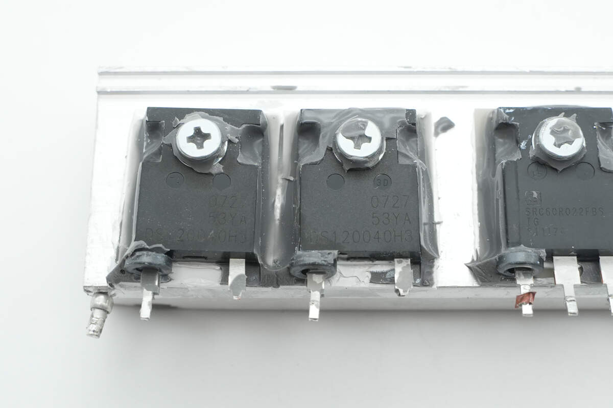
The PFC rectifiers are from Sanan, marked DS120040H3, model SDS120J40H3. They are SiC diodes rated at 1200 V, 40 A, in a TO-247-2L package.
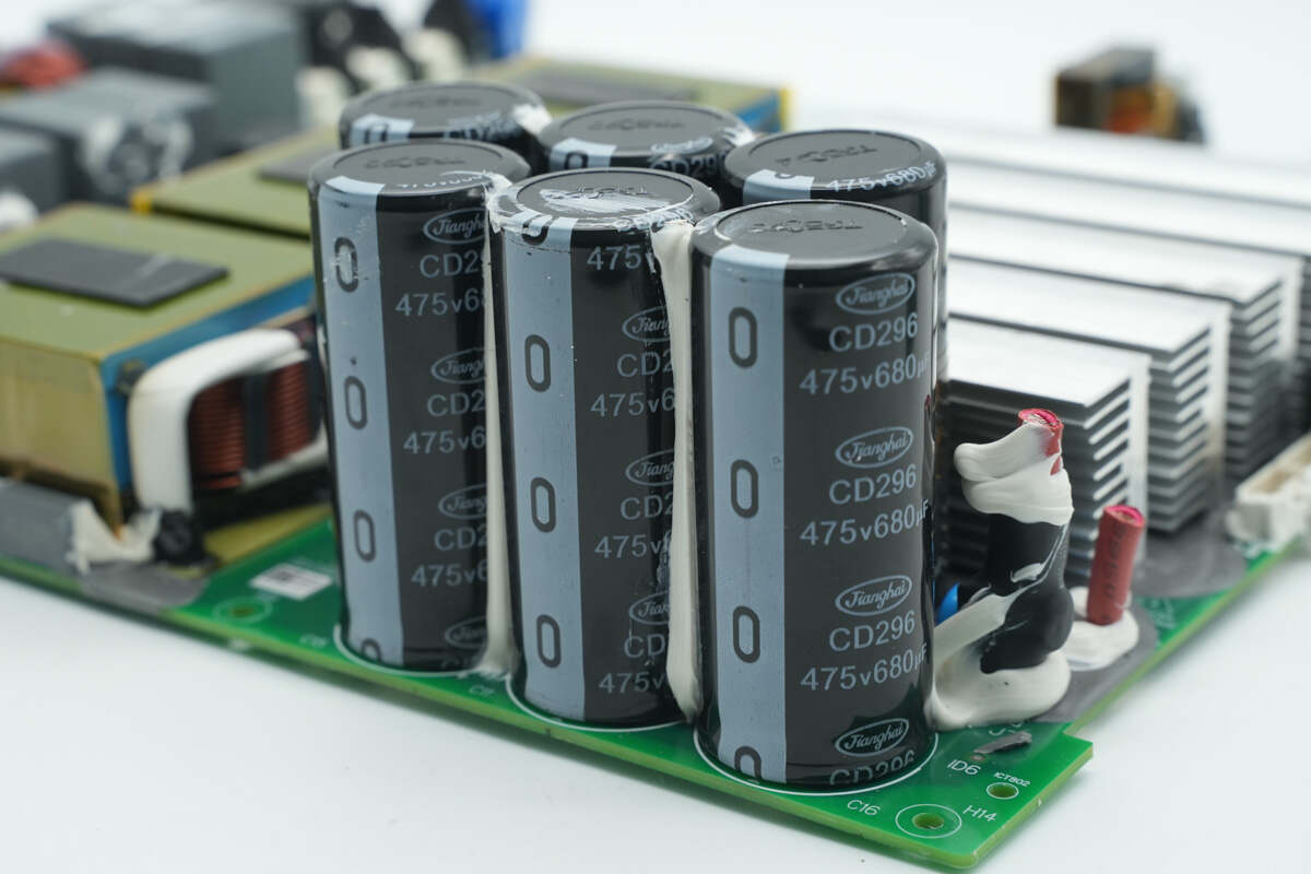
The output filter capacitors are from Jianghai, part of the CD296 series of long-life electrolytic capacitors, rated at 475 V, 680 μF. Adhesive is applied between the capacitors for reinforcement.
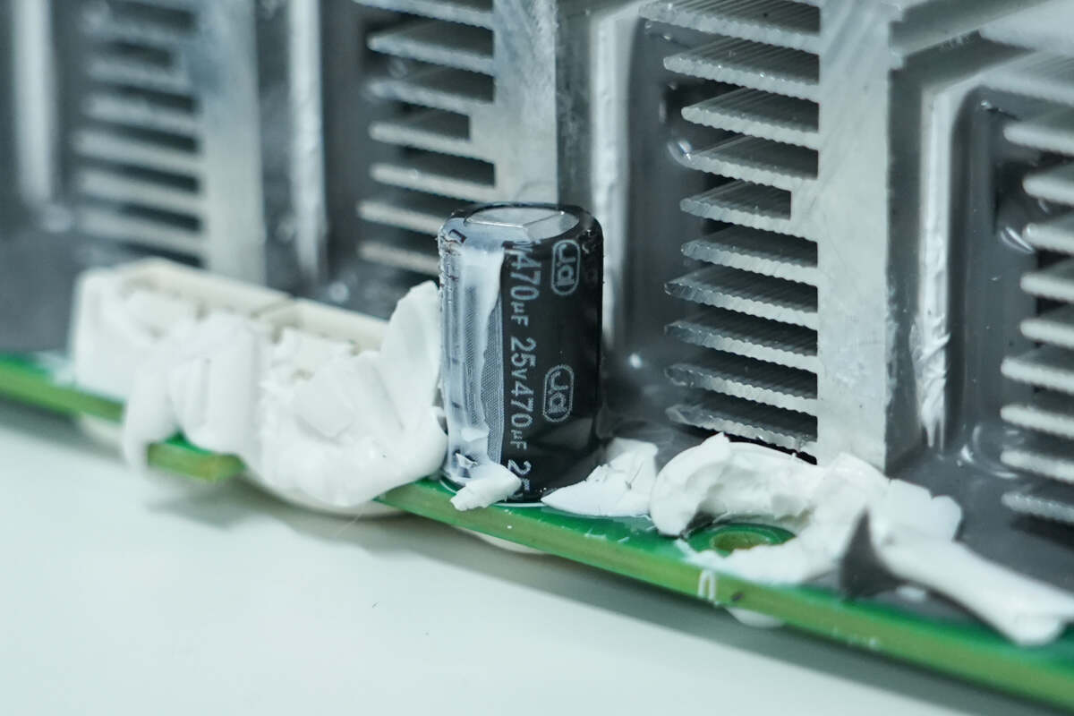
A filter capacitor is installed on the side of the heatsink, rated at 25 V, 470 μF.
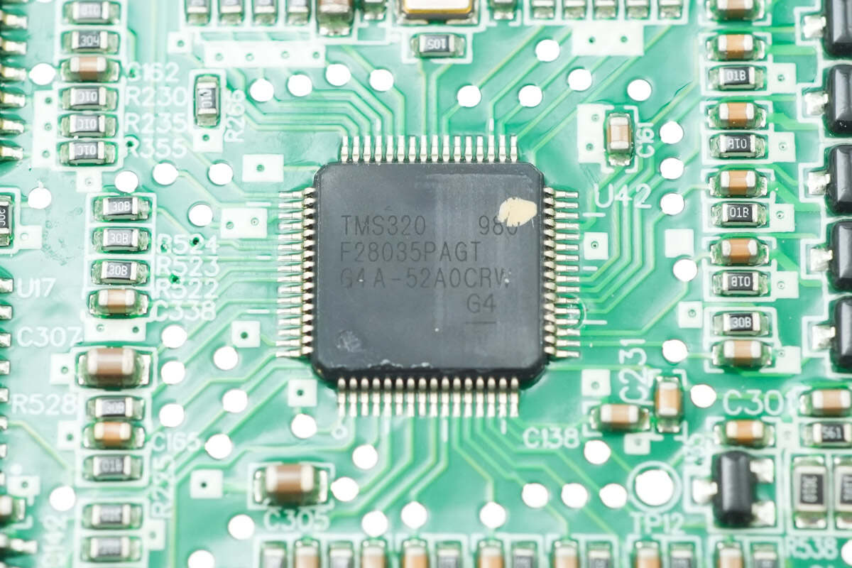
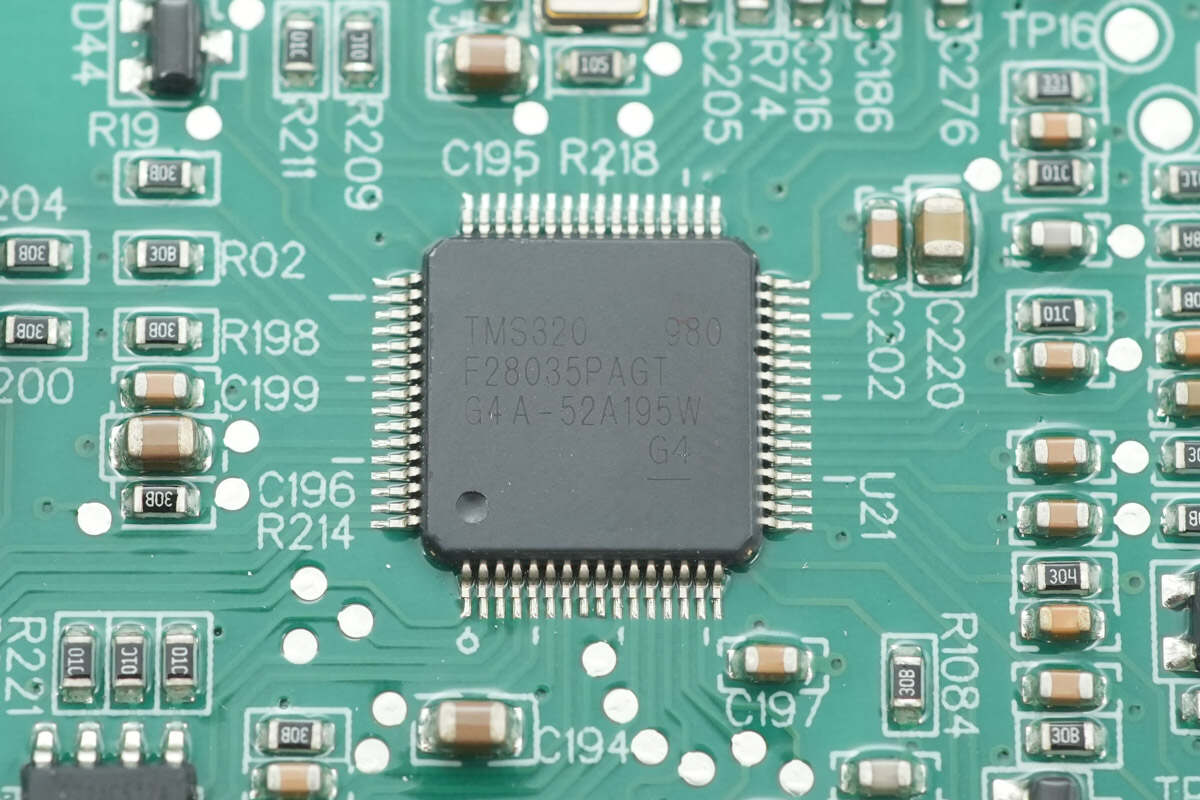
The PFC controller is from TI, part of the C2000 series of real-time microcontrollers, model TMS320F28035PAG. It features a 32-bit CPU core with a 60 MHz clock, supporting chained operations, fast interrupt response, and processing, and includes 128 KB of flash memory. It can be used in applications such as air conditioner outdoor units, DC-DC converters, inverters and motor control, onboard chargers (OBC), charging stations, and BLDC motor drives. The device comes in a TQFP-64 package.
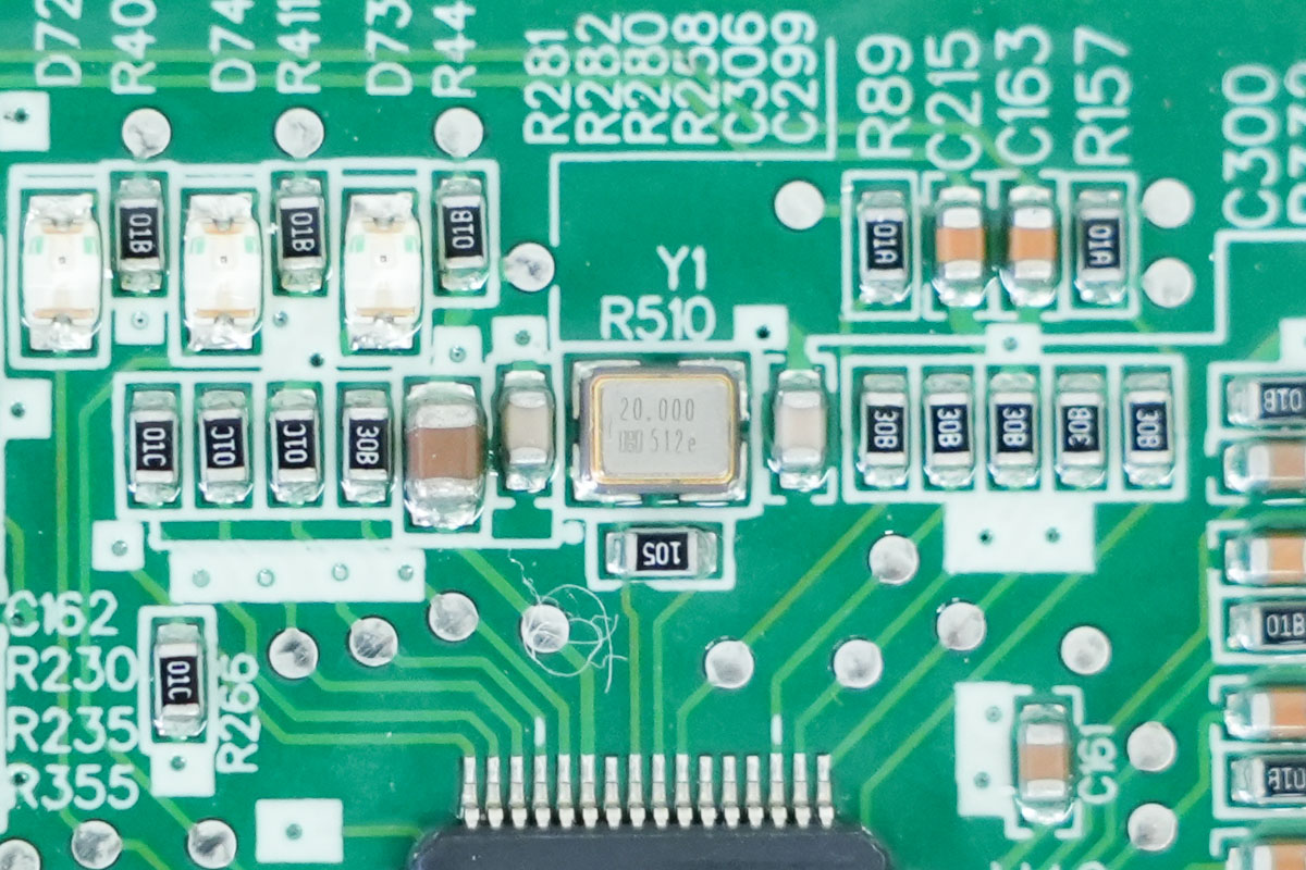
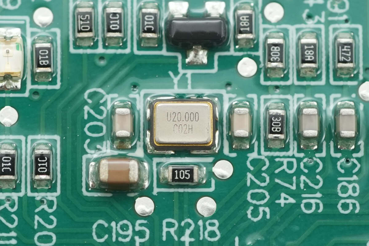
The PFC controller is paired with an external 20 MHz crystal oscillator.
Close-up of the LED indicators.
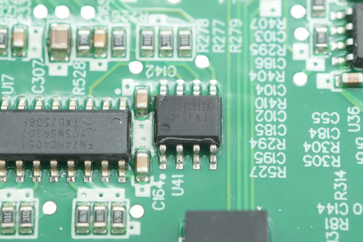
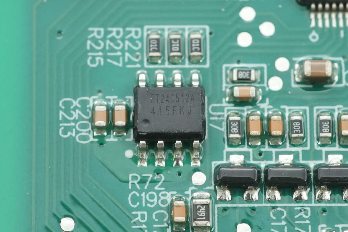
The memory is from FMD, model FT24C512A, with a capacity of 64 KB. It supports a supply voltage of 1.8–5.5 V and comes in an SOP-8 package.

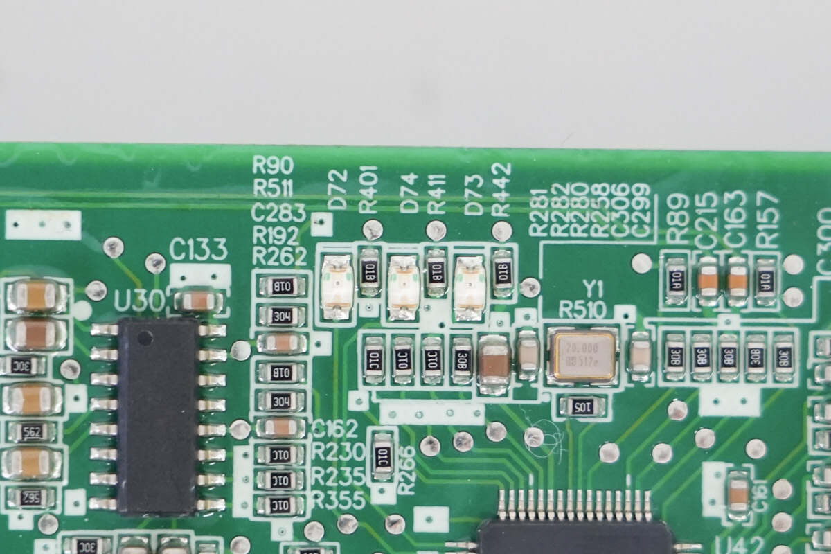
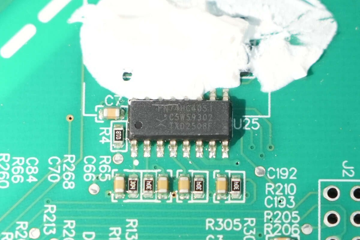
The analog multiplexers are from Nexperia, marked FN74HC4051, and come in an SO-16 package.
The operational amplifiers are from DIODES, model AS358MTR-E1. They are low-power dual op-amps in an SO-8 package.
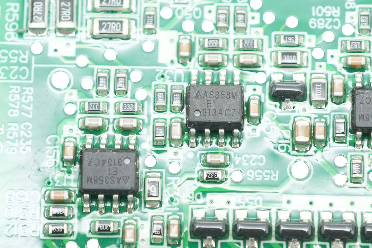
Two AS358MTR-E1 op-amps are also installed on the right side.
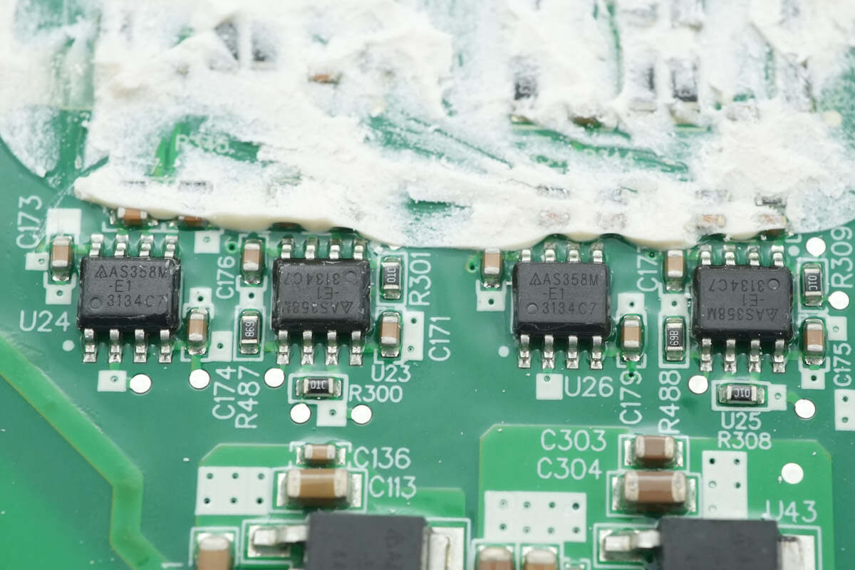
Close-up of the four DIODES AS358MTR-E1 op-amps.
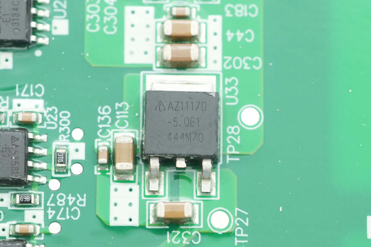
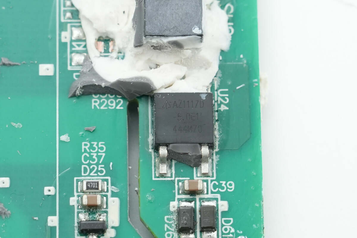
The regulator chip is from DIODES, model AZ1117D-5.0TRE1. It supports a 20 V input voltage, provides a 5 V output voltage, and delivers up to 1 A of output current. The device comes in a TO-252-2 package.
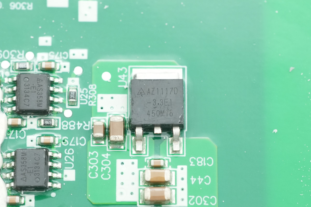
The other regulator chip is model AZ1117D-3.3TRE1, providing a 3.3 V output voltage.
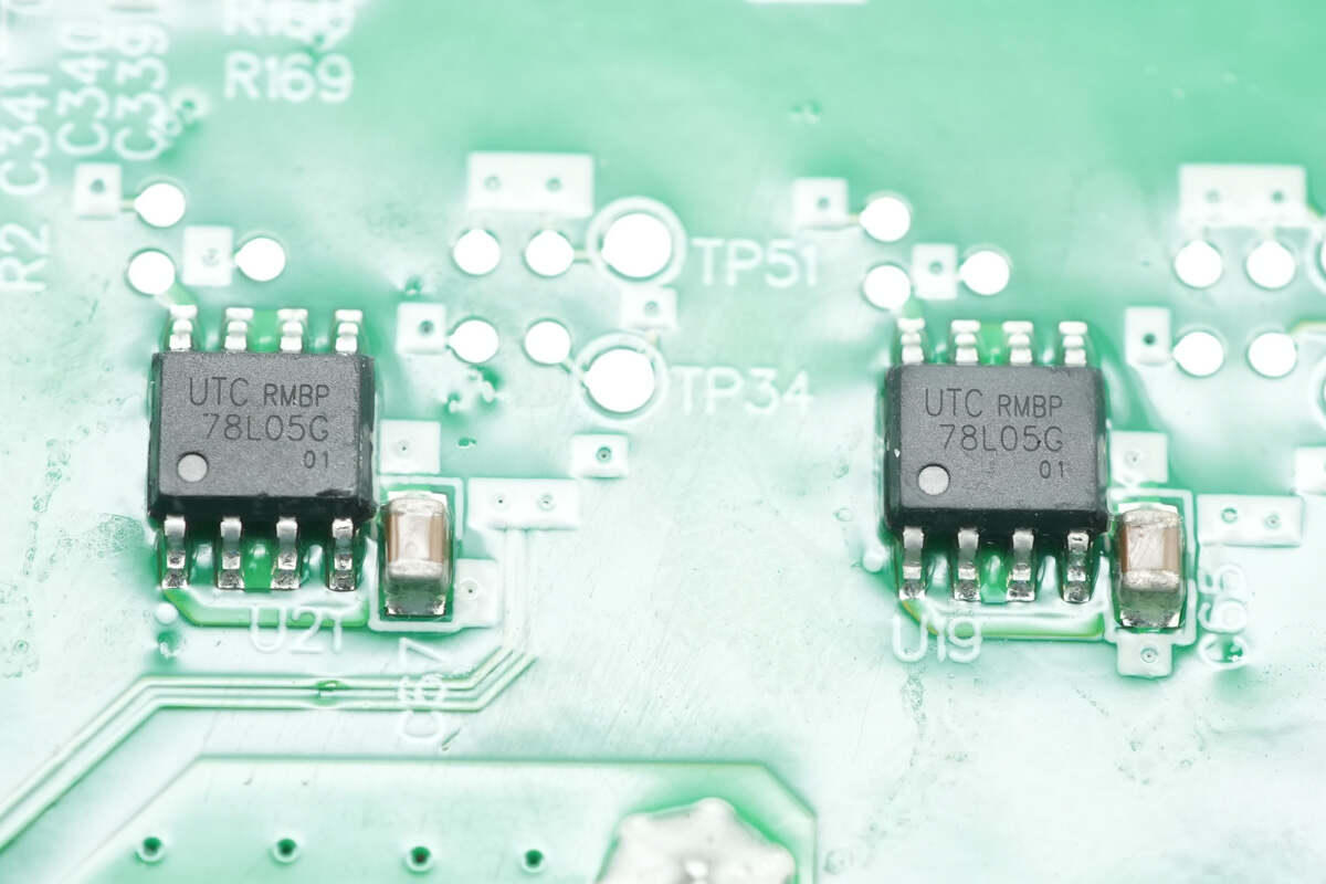
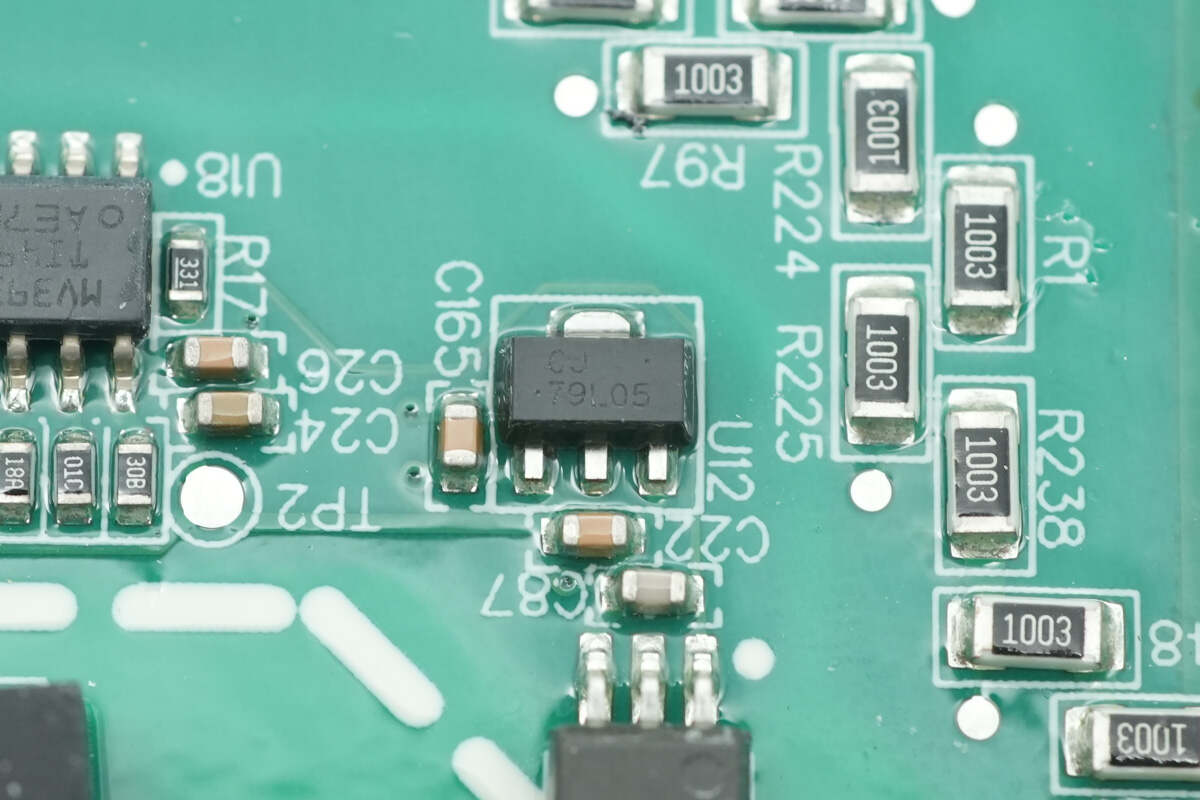
The two regulator chips are from Unisonic, model 78L05. They support a 30 V input voltage, provide a 5 V output voltage, deliver up to 100 mA of output current, and come in an SOP-8 package.
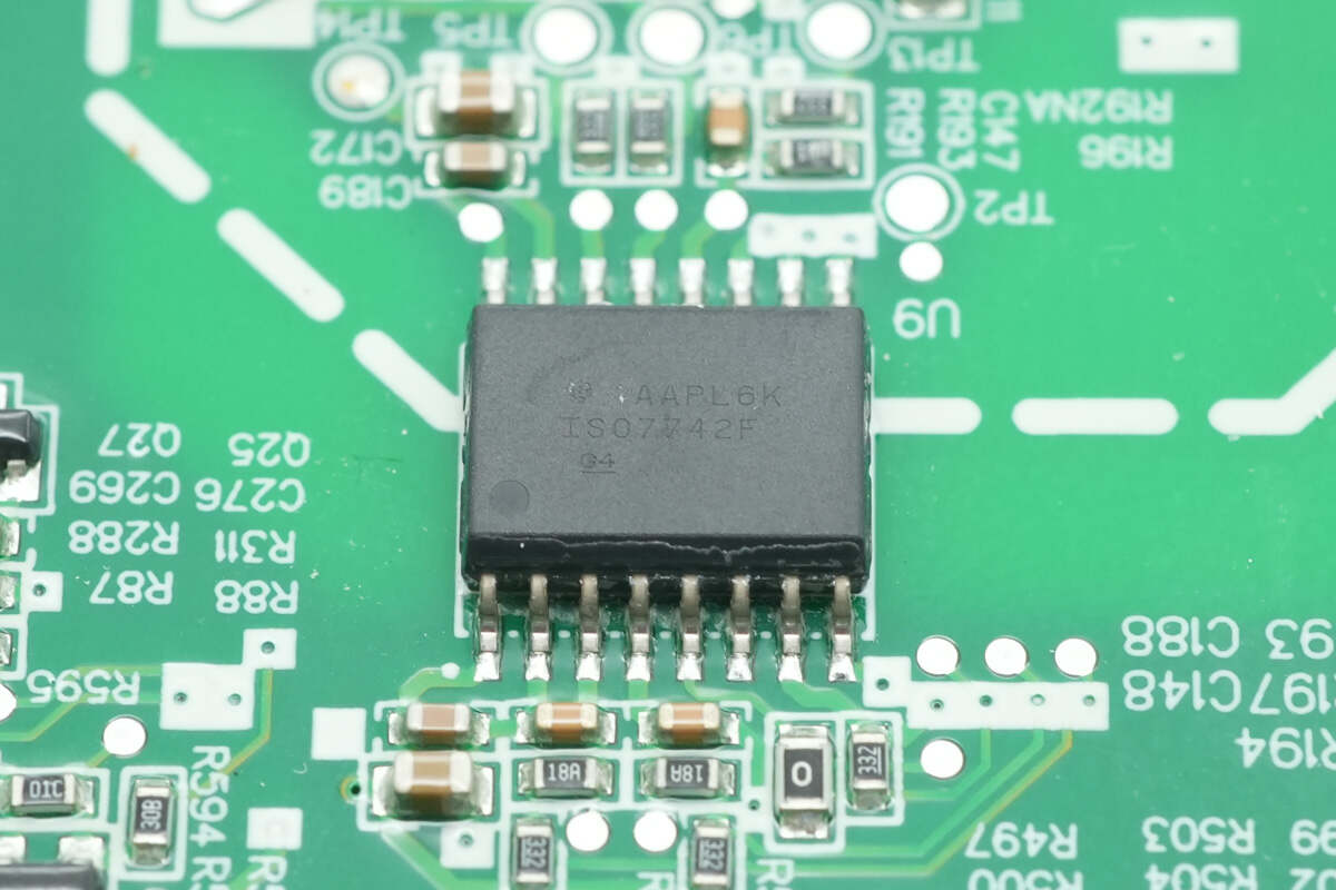
The isolated communication chip is from TI, model ISO7742F. It is a four-channel enhanced digital isolator, featuring two forward channels and two reverse channels, housed in a 16-pin SOIC (DW) package.
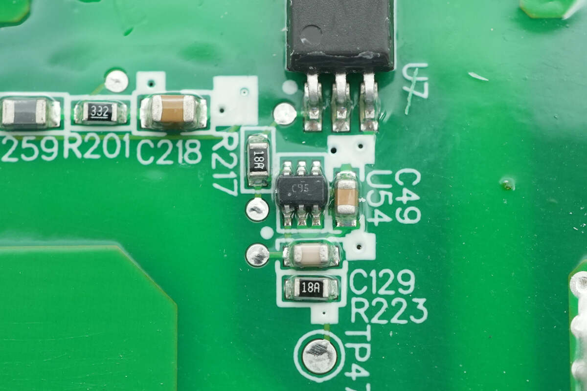
The buffer is from TI, marked C95, model SN74LVC1G34. It is a single-channel buffer supporting a 1.65–5.5 V operating voltage range, in an SC-70 package. Three units are used, corresponding to the three-phase PFC drive.
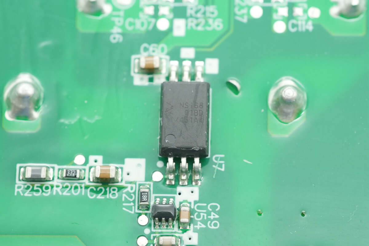
The isolated driver is from NOVOSENSE, model NSi6801BD. It is a single-channel isolated gate driver compatible with optocoupler input, supporting IGBT, MOSFET, and GaN applications. It provides a peak source/sink current of 5 A and comes in an SOW-6 package. Three units are used, corresponding to the three-phase PFC isolation.
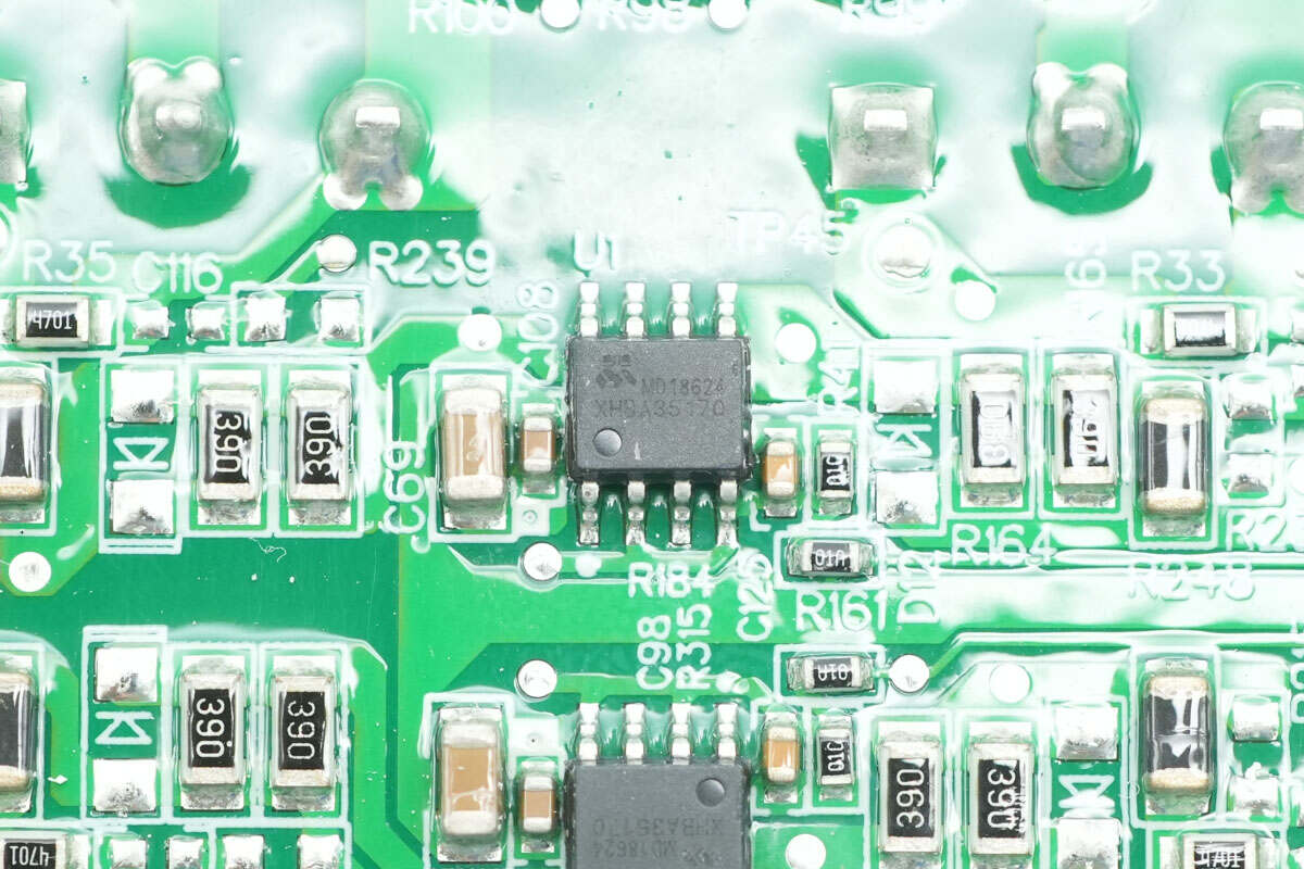
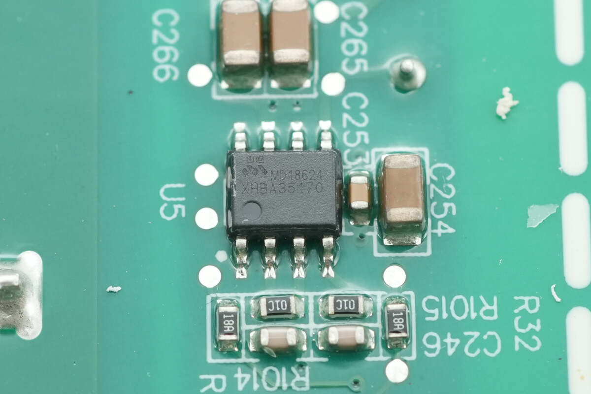
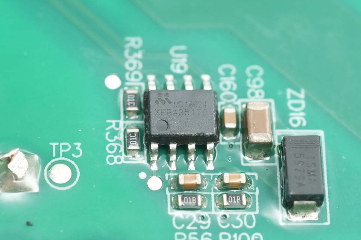
The drivers are from Meraki, model MD18624. They are dual low-side drivers with a peak drive current of 5 A, supporting a 4.5–26 V operating voltage and input pins rated for –10 to 26 V. They support switching frequencies up to 1 MHz and provide 5 A source and sink current. The devices come in an SOP-8 package, with six units used for driving the PFC MOSFETs.
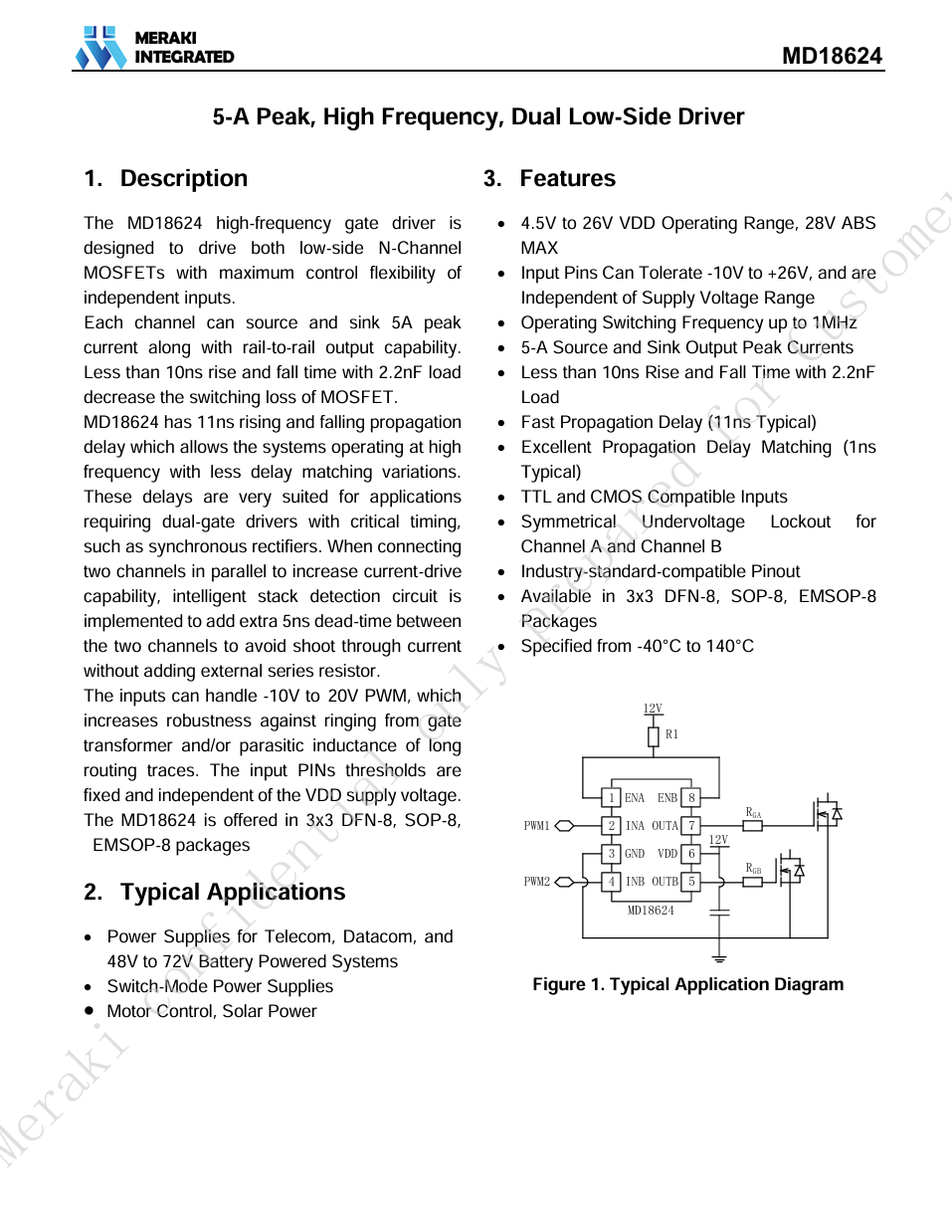
Here is the information about Meraki MD18624.
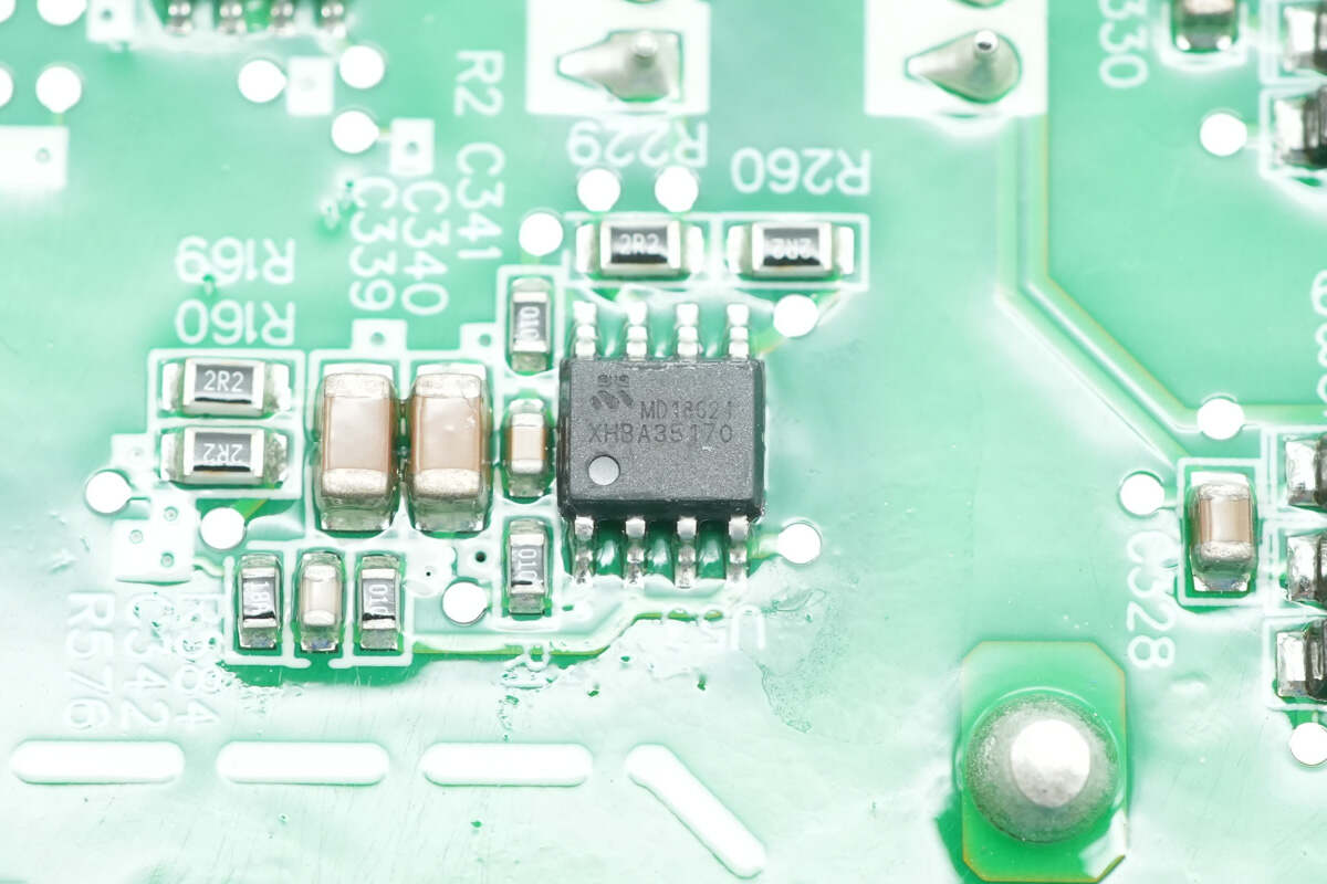
A separate MD18624 driver is also installed for the isolated power supply.
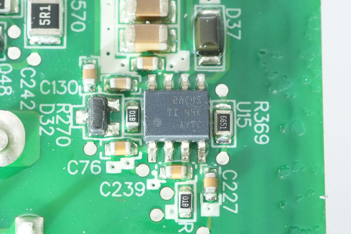
The auxiliary power supply chip is from TI, marked 28C45, model UCC28C45. It is a low-power current-mode controller supporting a 1 MHz switching frequency, housed in an SOIC-8 package.
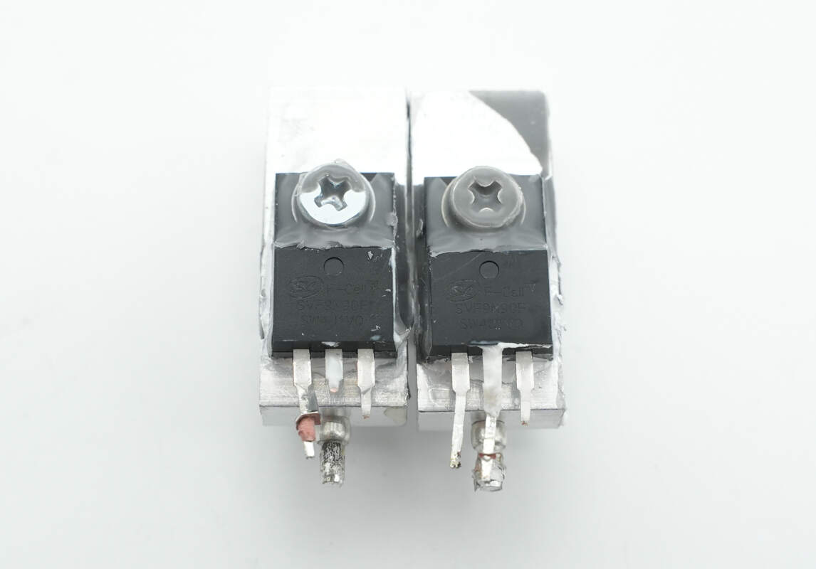
The auxiliary power supply MOSFETs are from Silan, model SVF9N90F. They are NMOS devices with a voltage rating of 900 V and an on-resistance of 1.1 Ω, housed in a TO-220F-3L package.
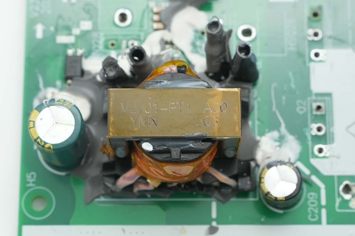
The auxiliary power supply transformer is wound with Litz wire.
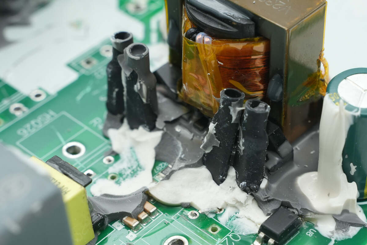
The components on one side of the transformer are wrapped with heat-shrink tubing.
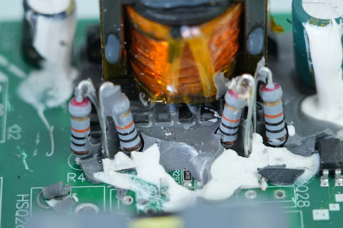
The heat-shrink tubing contains resistors.
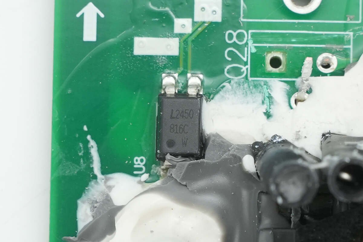
The feedback optocoupler is from LITEON, model LTV-816C.
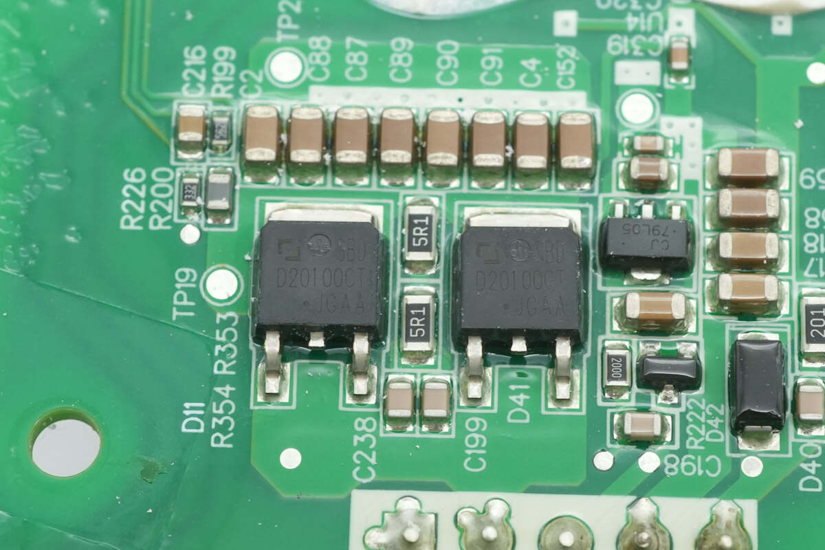
The rectifiers are from JSCJ, model SBDD20100CT. They are Schottky diodes, rated for 100 V and 20 A, and come in a TO-252-2L package.

The regulator chip is from JSCJ, model CJ79L05. It supports an input voltage of –30 V, provides a –5 V output, and delivers up to 100 mA of output current. The device comes in an SOT-89-3L package.
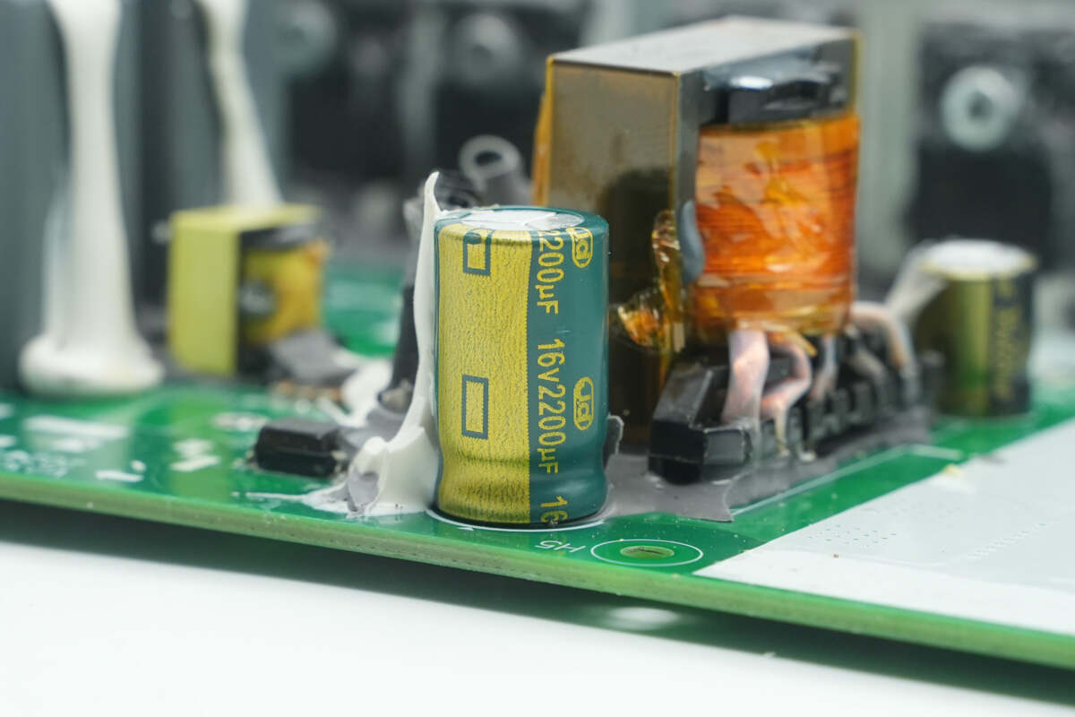
The filter capacitor is from JD, rated at 16 V, 2200 μF.
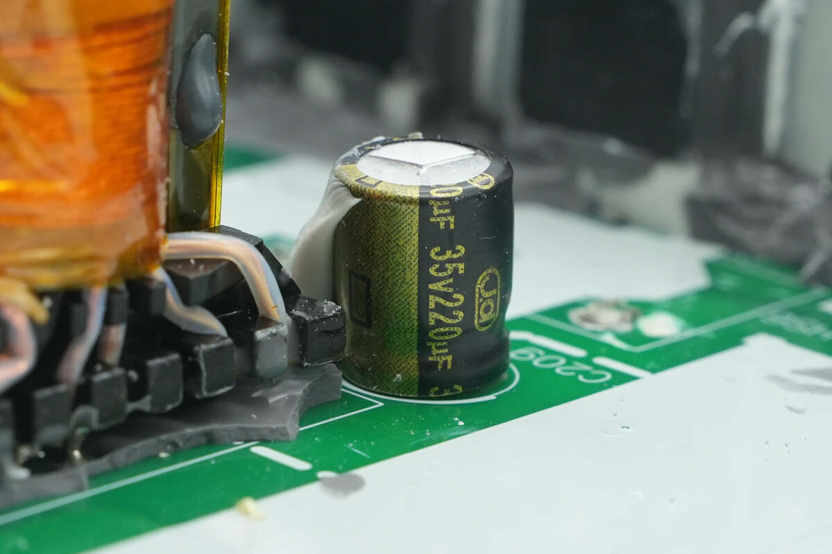
The other filter capacitor is rated at 35 V, 220 μF.
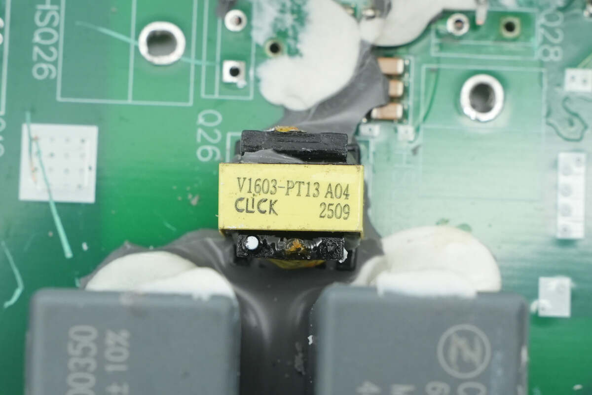
Close-up of the isolation transformer used for the power supply.
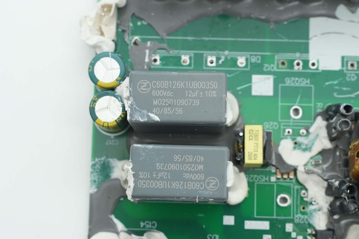
The two film capacitors are from Zhongxing, rated at 600 V, 12 μF.
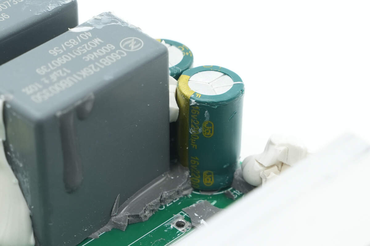
The electrolytic capacitor is rated at 16 V, 2200 μF.
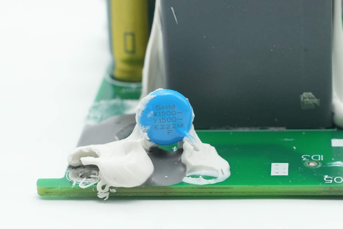
The safety Y capacito is from SHM.
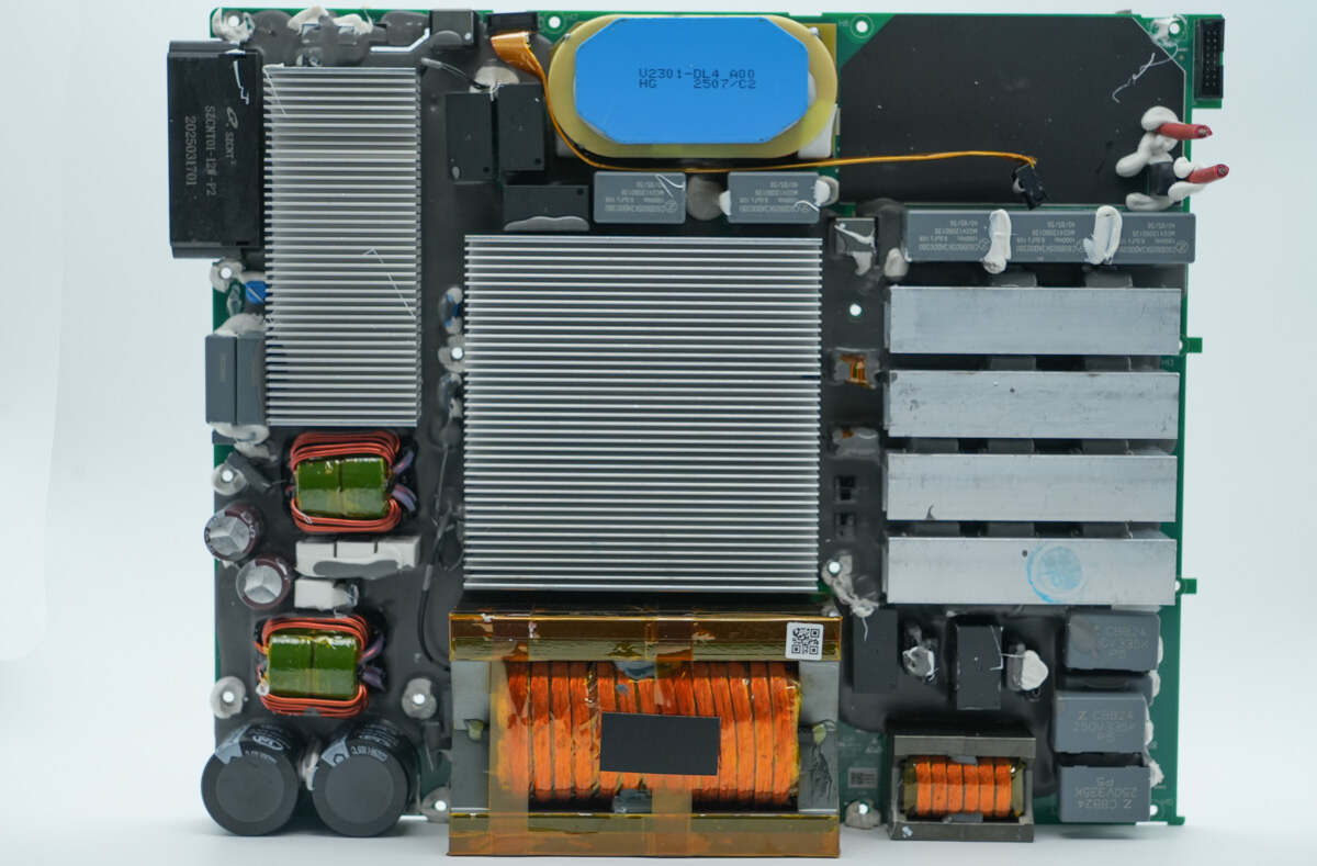
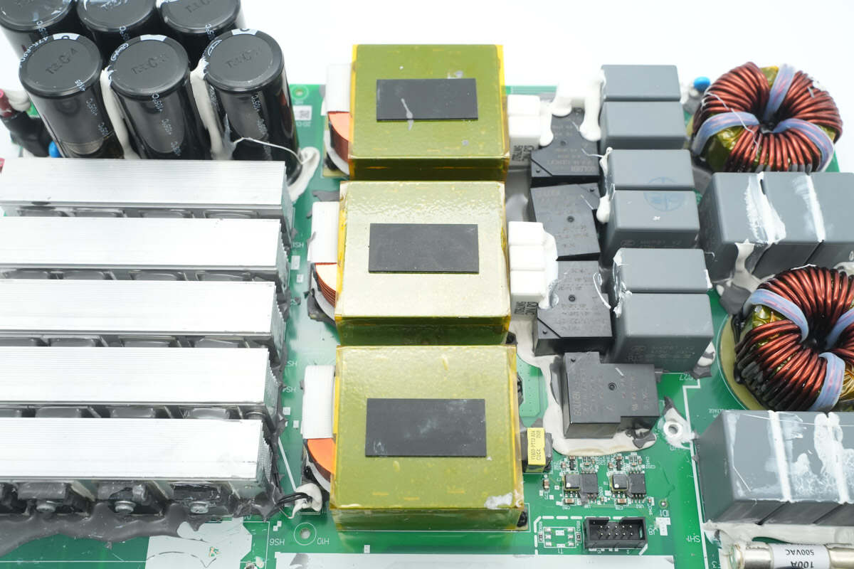
The front side of the LLC module features film capacitors, LLC MOSFETs, resonant capacitors, resonant inductors, relays, filter inductors, rectifiers, an LLC transformer, and filter electrolytic capacitors, among other components.

The rear side includes the LLC controller, analog multiplexers, drivers, isolation chips, synchronous buck converter, and other components.
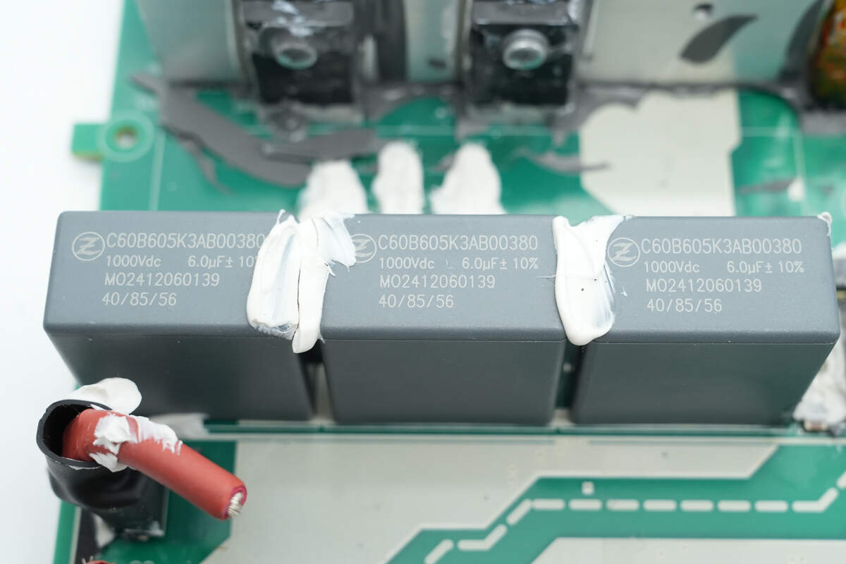
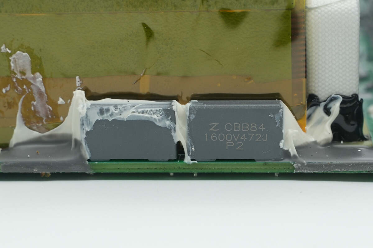
The input film capacitors are from Zhongxing, rated at 1000 V, 6 μF.
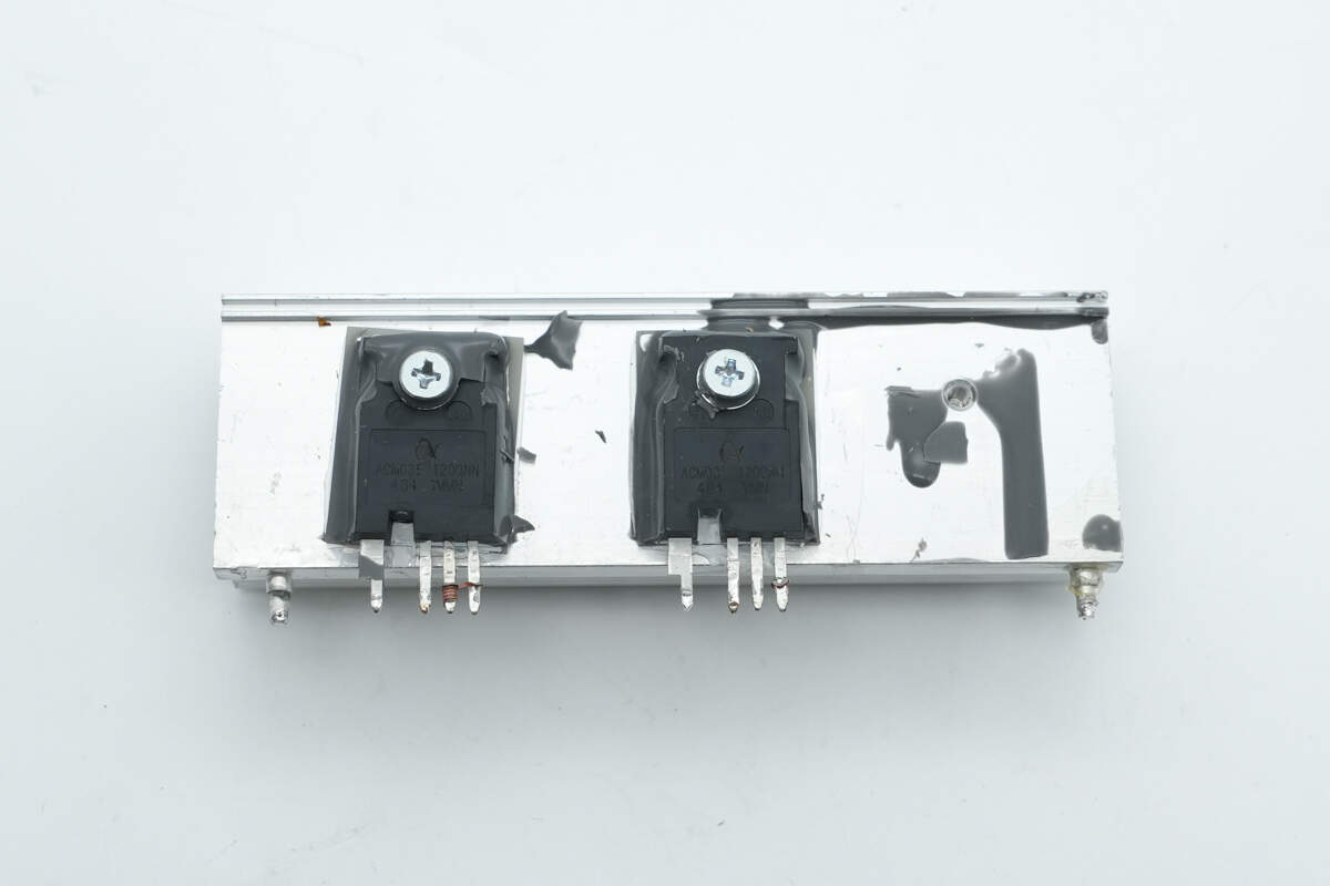
The front side of the heatsink features two LLC MOSFETs.
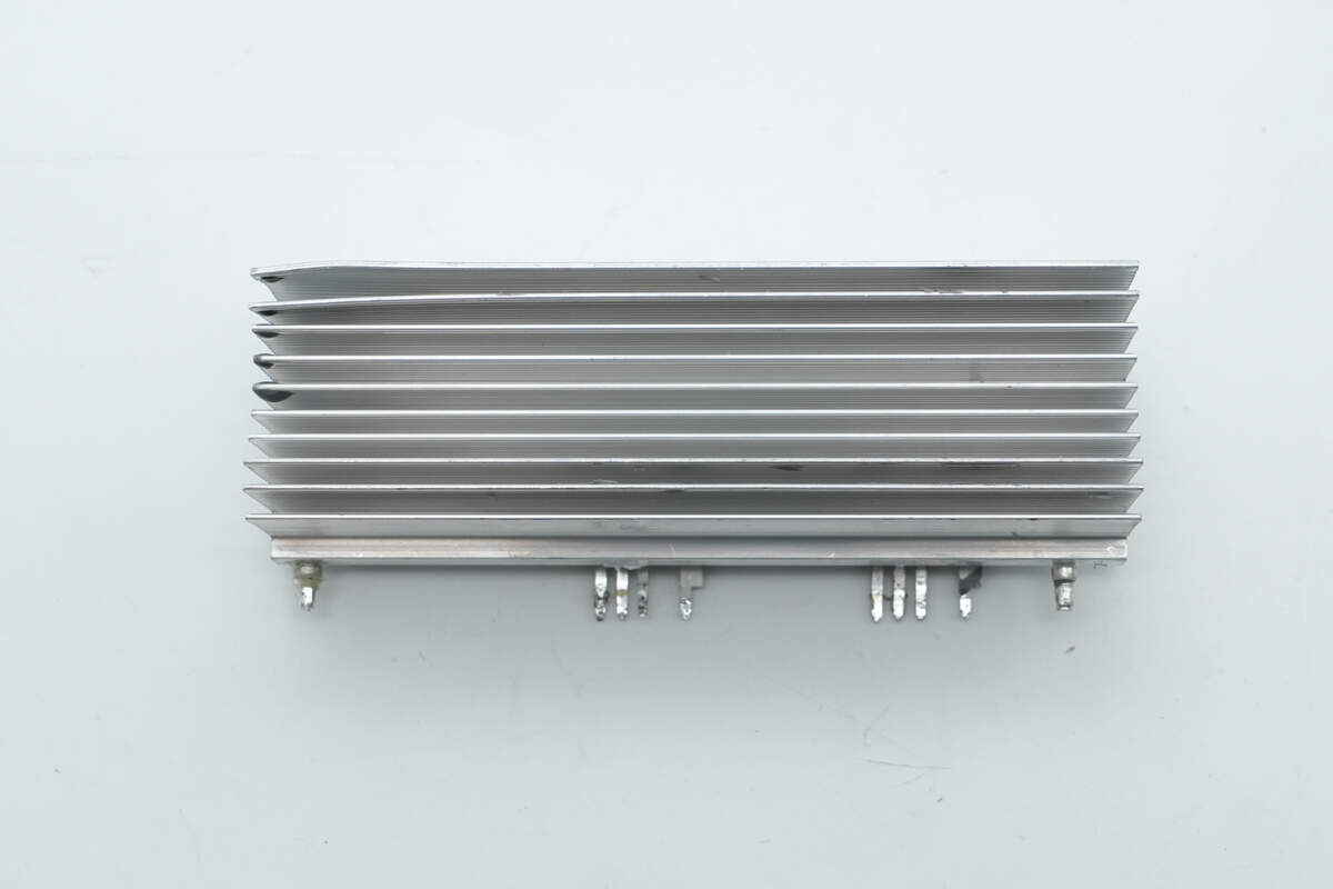
The back side of the heatsink features a grille to increase the cooling surface area.
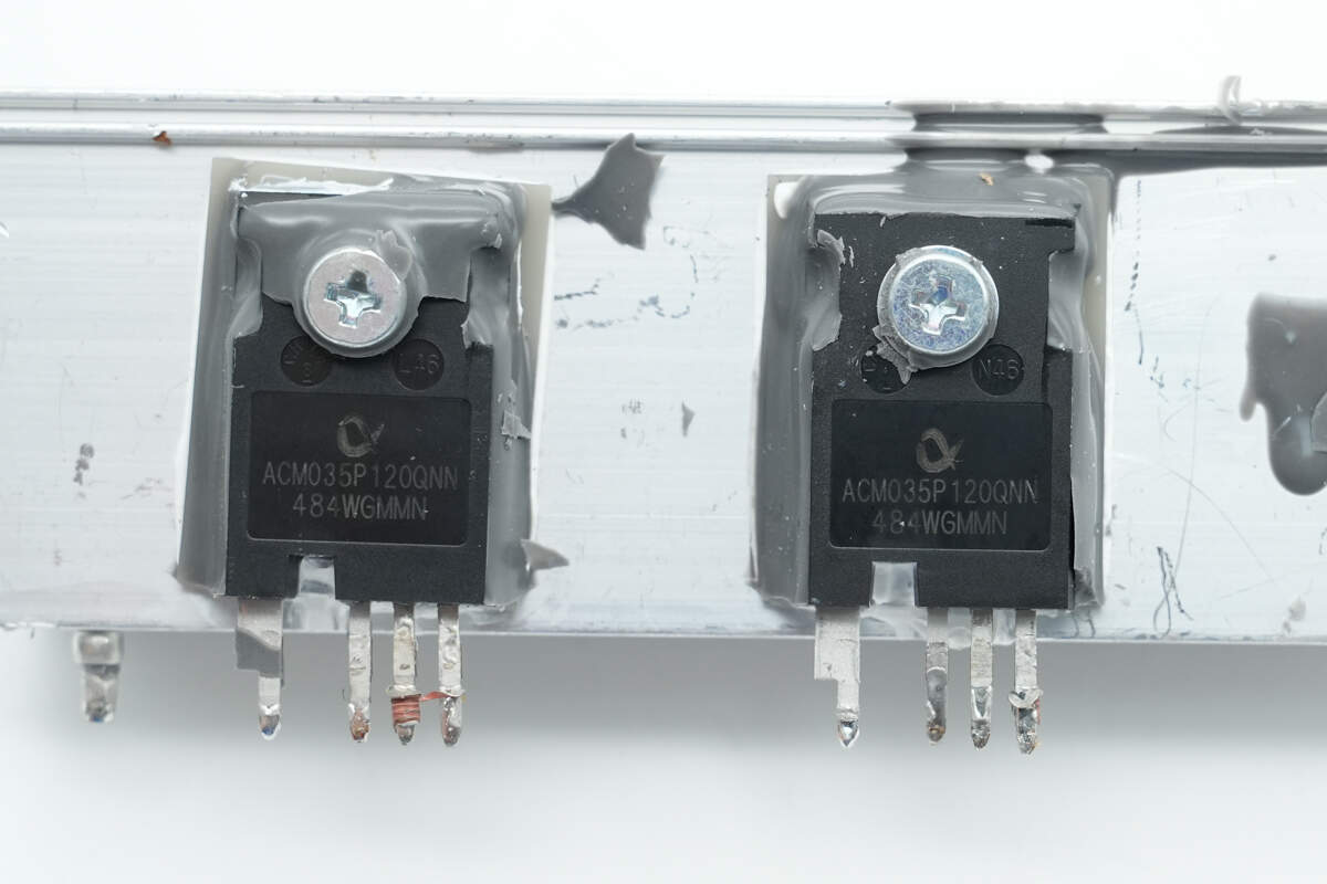
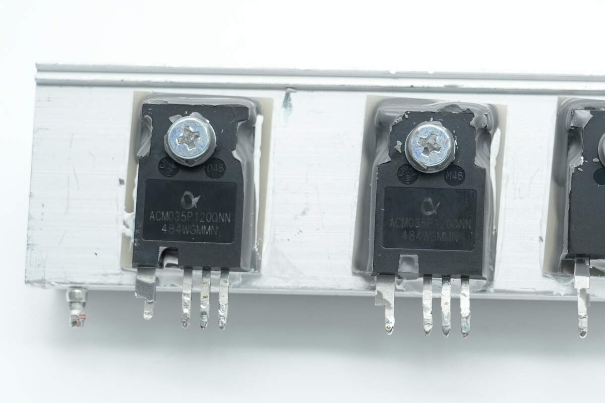
The LLC MOSFETs are from APS, model ACM035P120QNN. These 1200 V SiC MOSFETs feature an on-resistance of 33 mΩ and come in a TO-247-4 package. Rated for industrial use, they are suitable for motor drives, solar and wind inverters, electric vehicle charging, and UPS applications.
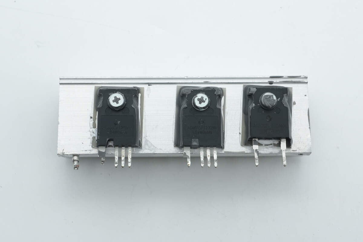
The other heatsink front side is equipped with two LLC MOSFETs and one SiC diode.
The LLC MOSFETs use the APS ACM035P120QNN.
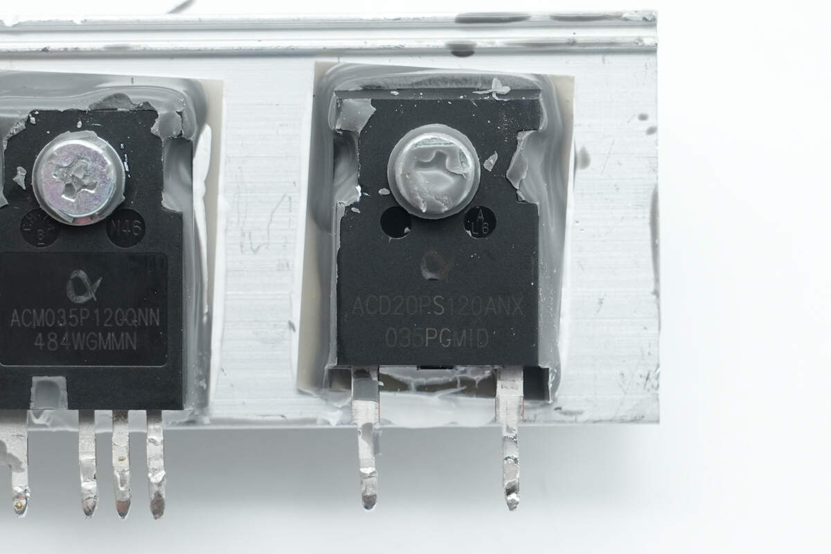
The SiC diode is from APS, model ACD20PS120ANX. It is rated at 1200 V and 20 A, and comes in a TO-247-2 package.
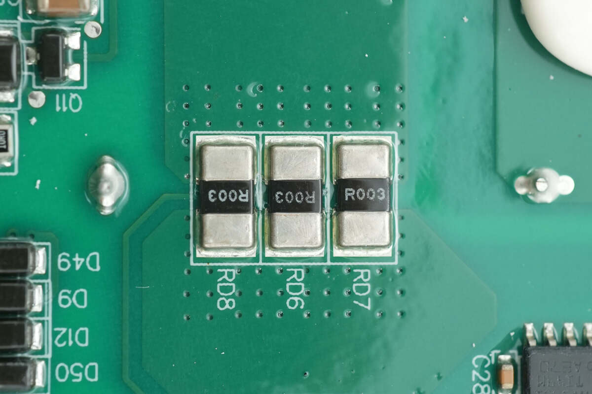
Three 3 mΩ current-sense resistors are connected in parallel for input current detection.

The voltage comparator is from TI, marked MV393I, model LMV393. It is a dual-channel general-purpose low-voltage comparator in an SOIC-8 package.
The regulator chip used is JSCJ CJ79L05.
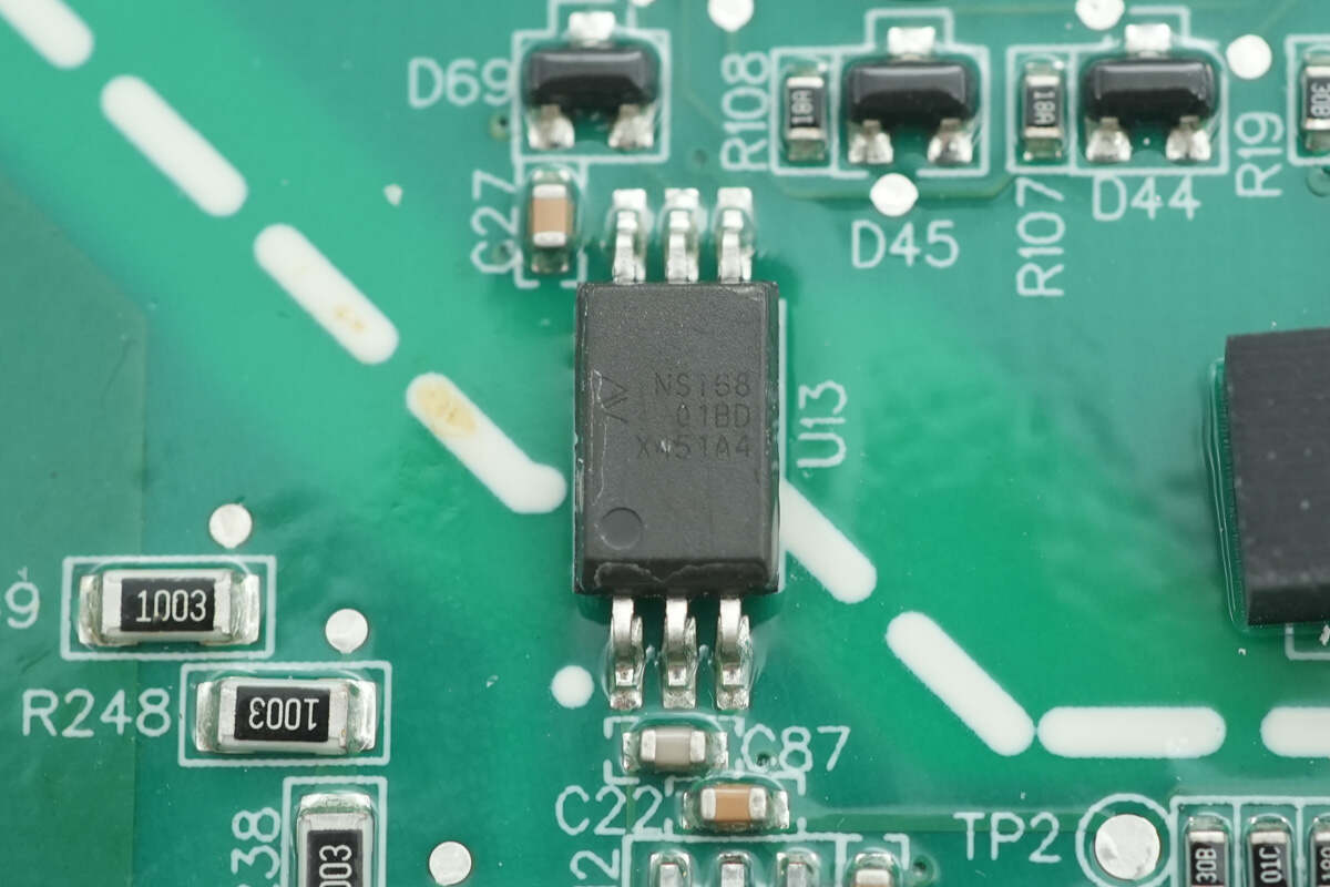
The isolation driver used is NOVOSENSE NSi6801BD.
The film capacitor is rated at 250V and 0.56μF.
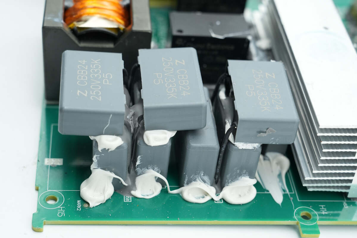
Seven resonant capacitors are used in parallel.
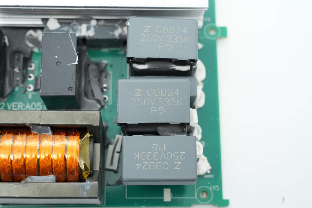
The resonant capacitors are rated at 250V 3.3μF.
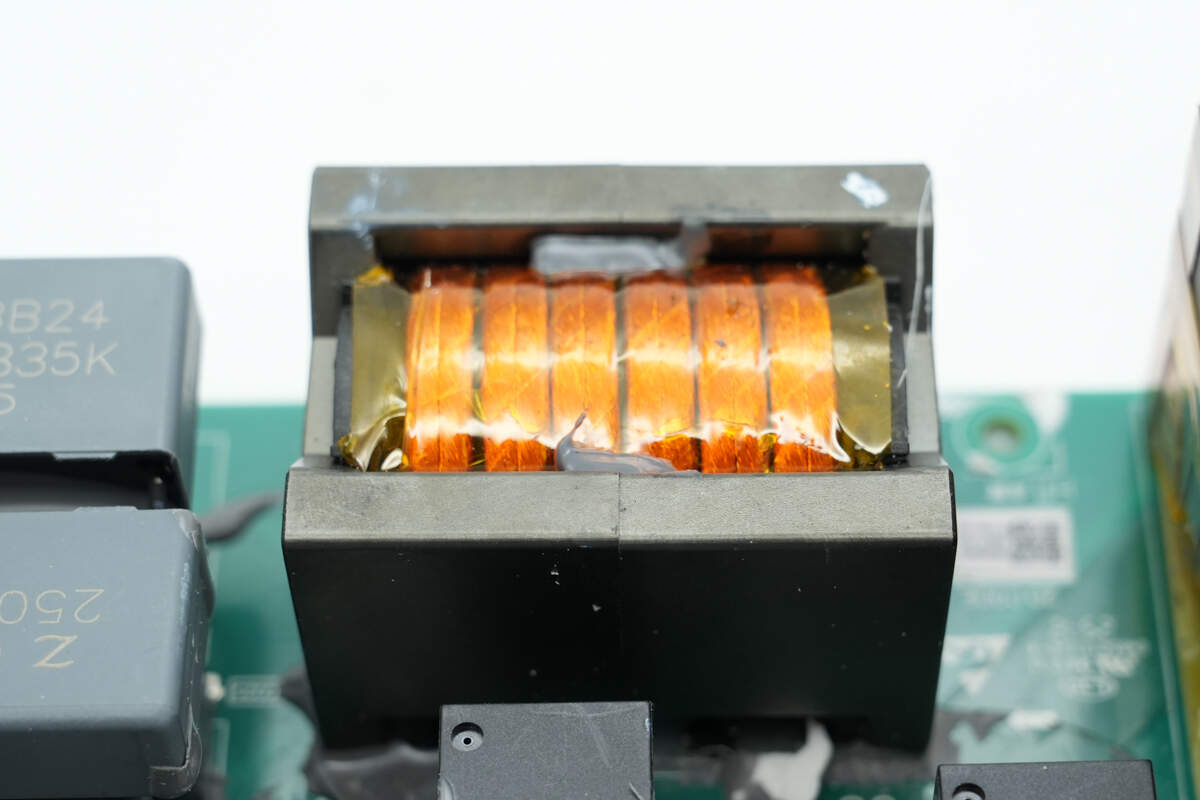
The resonant inductor is wound with Litz wire.
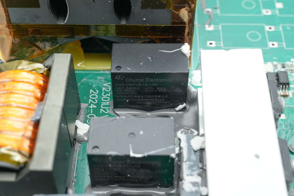
Two switching relays are from Churod, model CHC-D90/VB-12LAB. They feature a contact rating of 90 A and a coil voltage of 12 V.
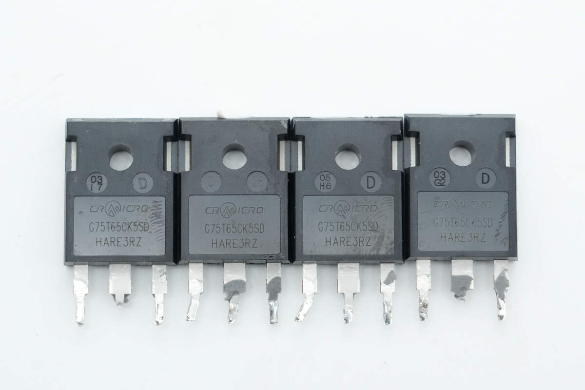
Four IGBTs are from CR MICRO, model CRG75T65CK5SD. They are rated at 650 V and 75 A, and come in a TO-247 package.
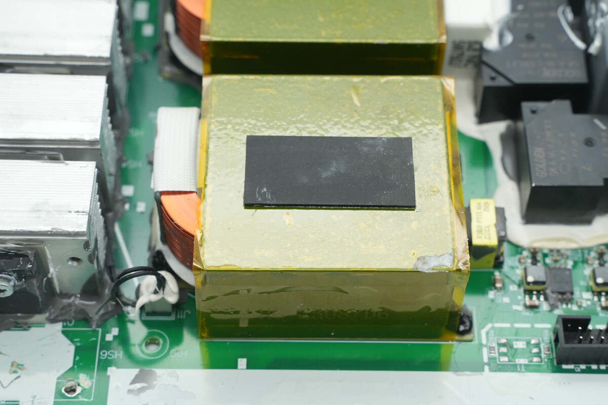
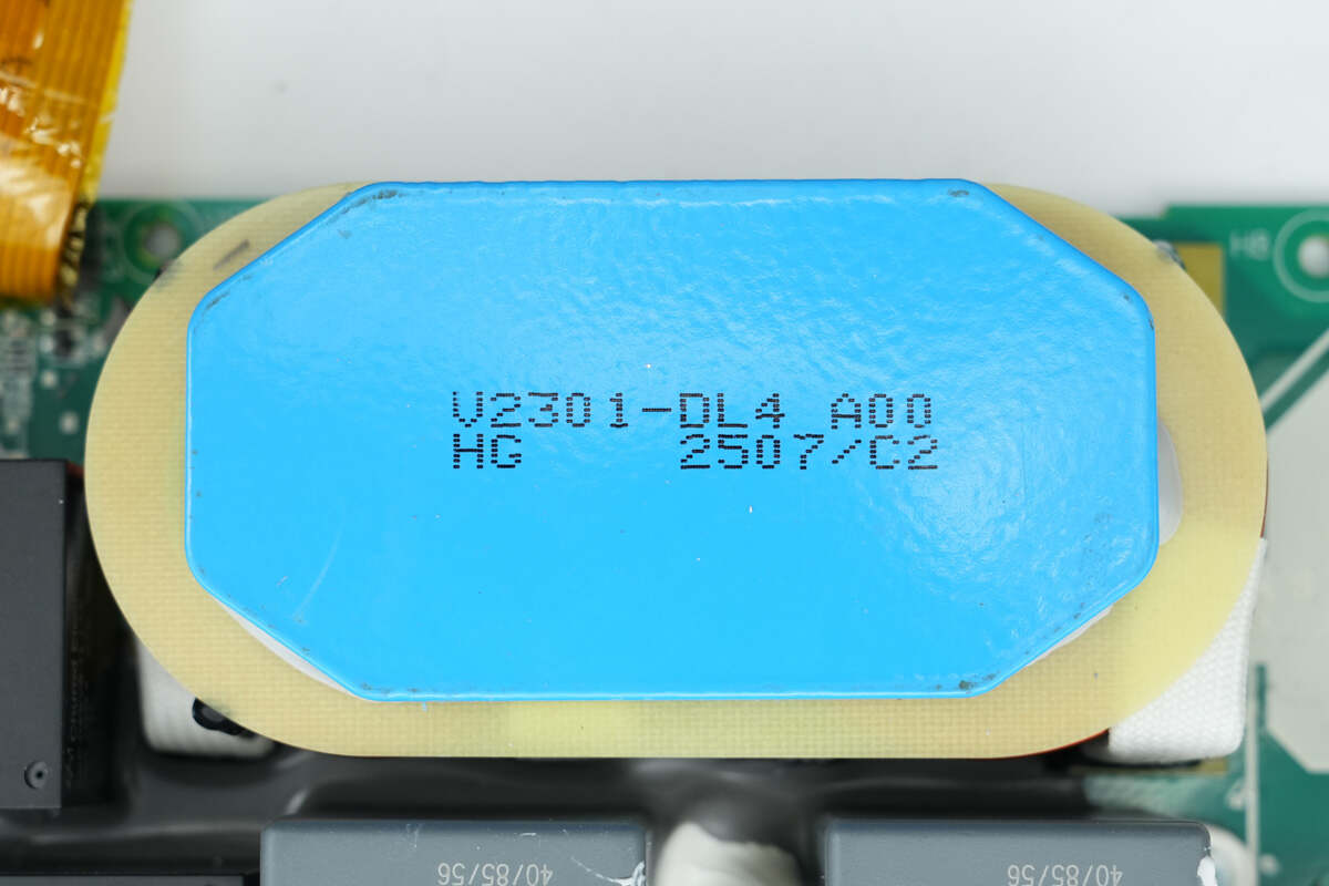
The transformer is wound with Litz wire, and the magnetic core is insulated with high-temperature adhesive tape.
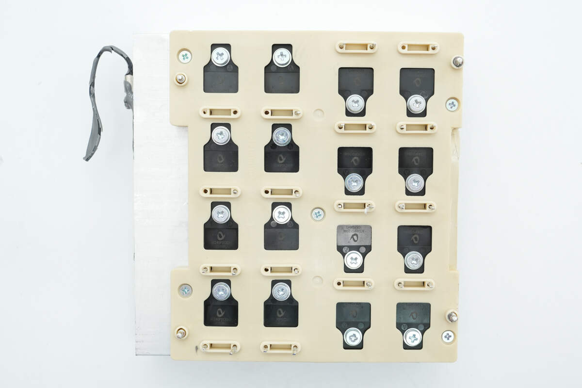
Sixteen rectifiers are mounted on the heatsink and secured with a plastic sealing bracket fastened by screws.

Rectifiers are fixed to the heatsink using screws.

The SiC diode is from APS, model ACD40PD120AN. It is rated at 1200 V and 40 A, and comes in a TO-247-2 package.
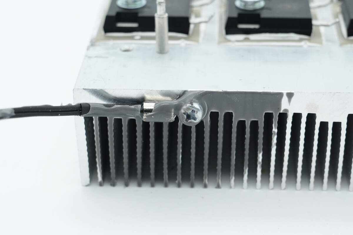
A thermistor is mounted on the side of the heatsink and secured with a screw.

Both film capacitors are rated at 1000V 6μF.
The filter inductor is wound with flat copper wire and insulated with a bakelite plate.
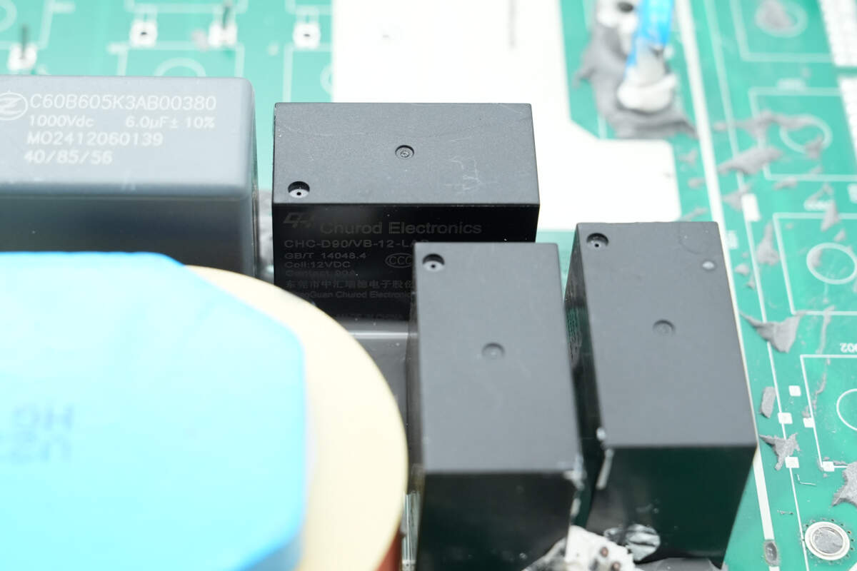
The three switching relays use Churod CHC-D90/VB-12LAB.
Three sampling resistors are connected in parallel to detect the output current.
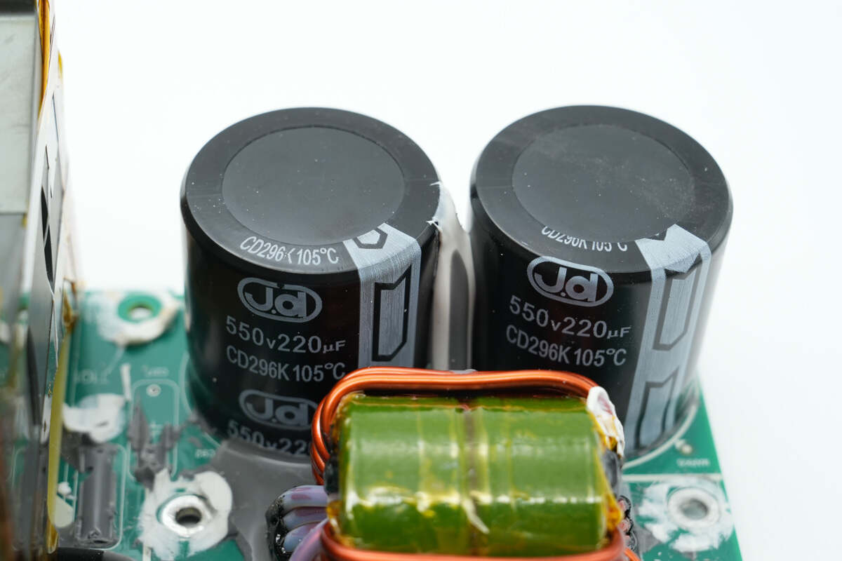
The two filter capacitors are from Jd and are rated for 550V 220μF.
The filter inductor is wound with enameled wire, and the magnetic core is wrapped with high-temperature insulating tape.
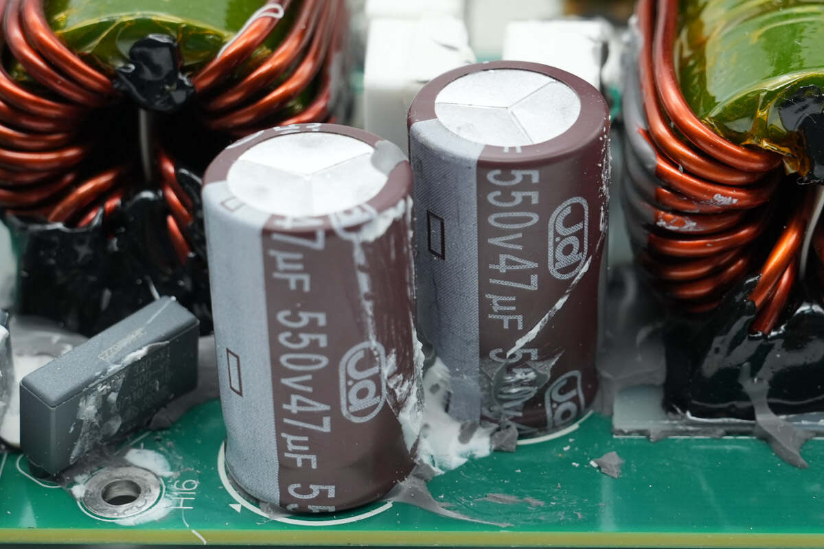
The two filter capacitors are rated at 550V 47μF.
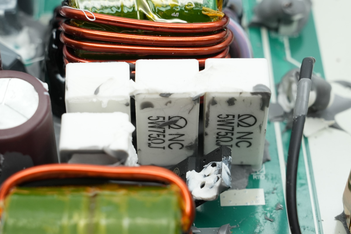
Four discharge resistors are connected in series, with a specification of 5W 75Ω.
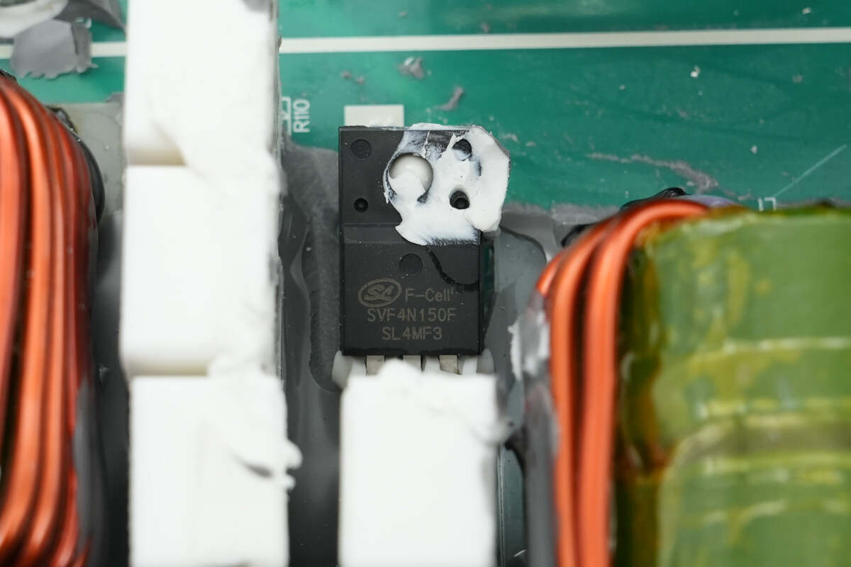
The discharge MOSFET is from Silan, model SVF4N150F, NMOS, with a withstand voltage of 1500V, on-resistance of 5Ω, and a TO-220F-3L package.
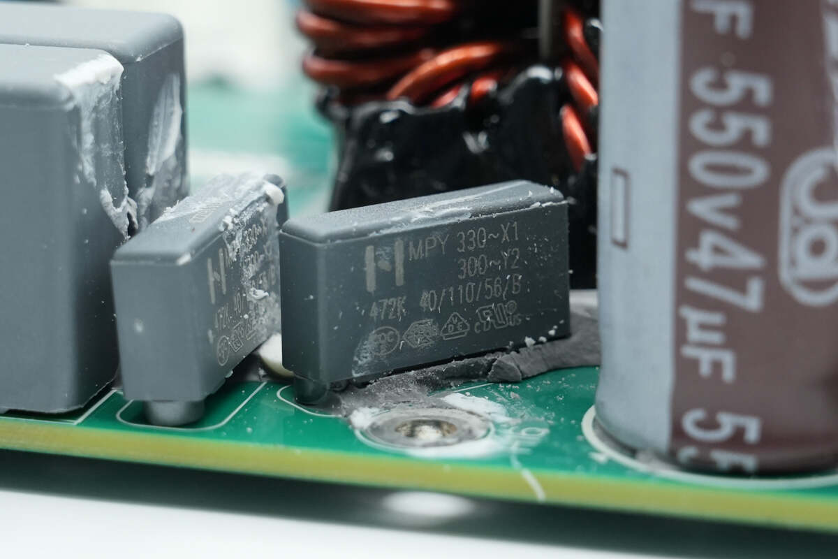
Close-up of film Y capacitors.
Close-up of another filter inductor.
The two film capacitors are rated at 1200V 1μF.
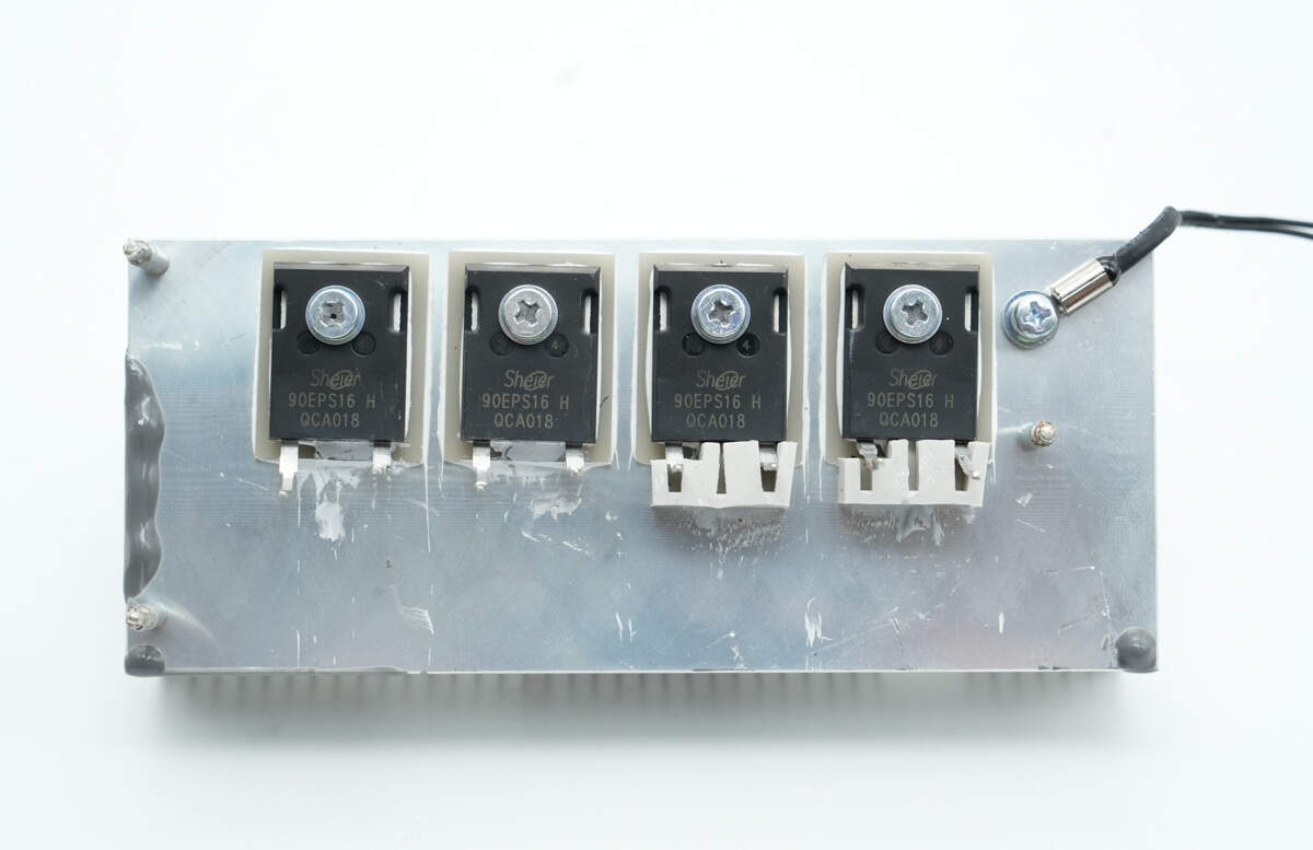
The output reverse-protection diodes and the thermistor are mounted on this heatsink.
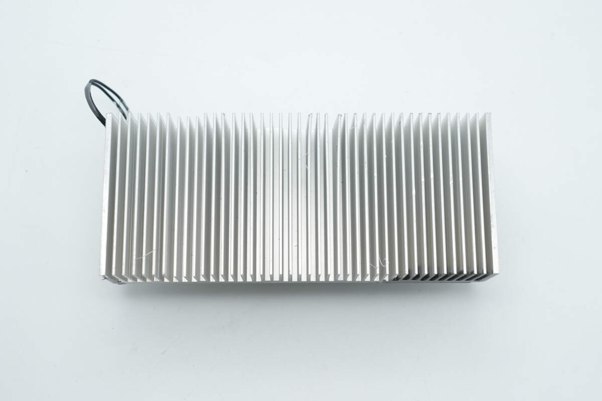
The back side of the heatsink features a grille structure to increase the heat dissipation area.
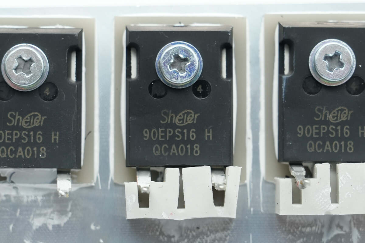
The reverse-protection diodes are from Sheier, model 90EPS16 H. They are rated at 1600 V and 90 A, and come in a TO-247 package.
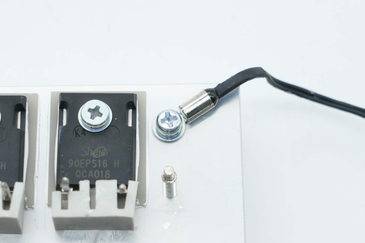
Close-up of a thermistor used to detect the temperature of the heatsink.
The LLC controller uses the TI TMS320F28035PAG, the same model as the PFC controller.
The chip has an external 20.000MHz crystal oscillator.
The memory used is FMD FT24C512A.
The analog multiplexer used is the Nexperia FN74HC4051.
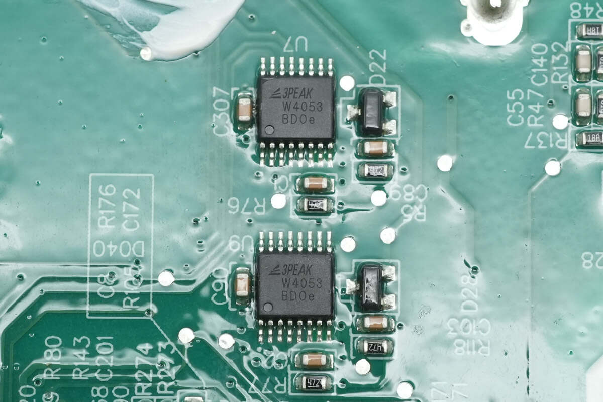
The analog switches are from 3PEAK, model TPW4053. It is a three-single-pole double-throw analog switch with three digital selection inputs and is packaged in a TSSOP-16 package.
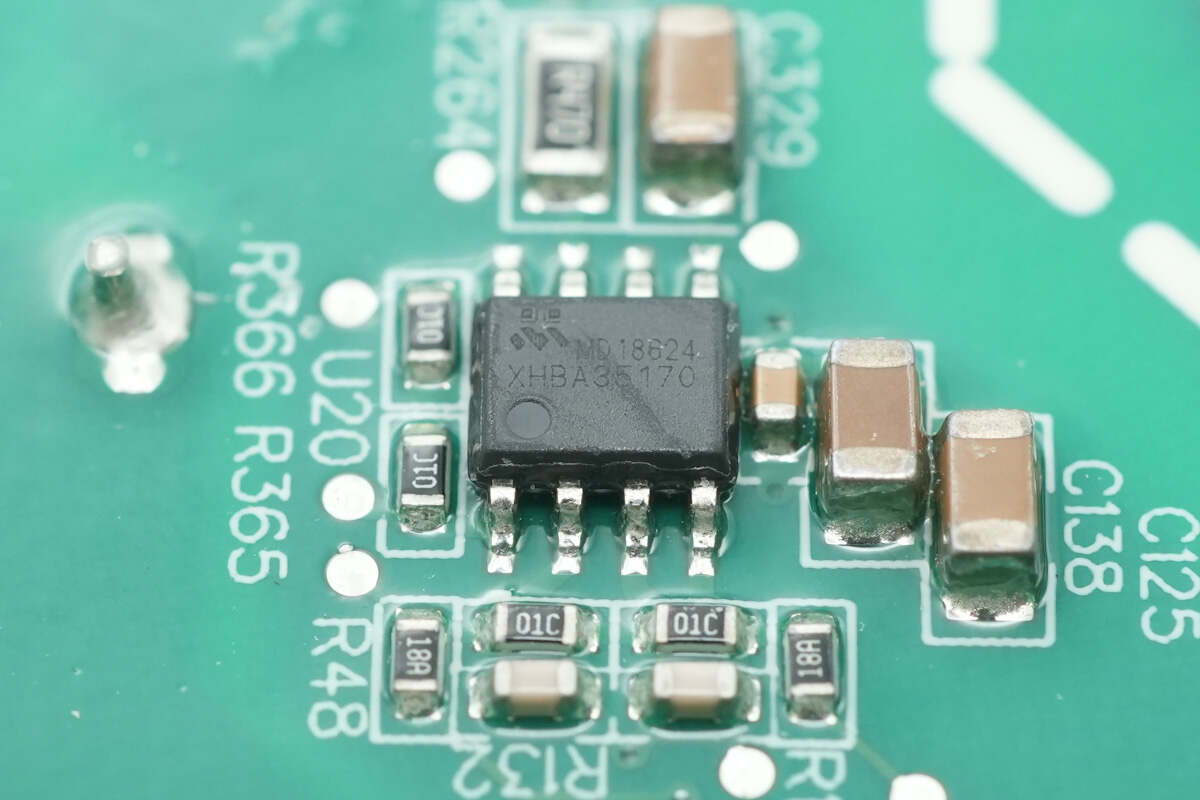
The driver used for the isolated power supply transformer is the Meraki MD18624.
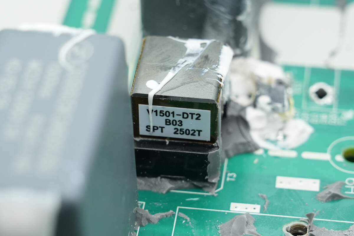
Close-up of the isolation power supply transformer.
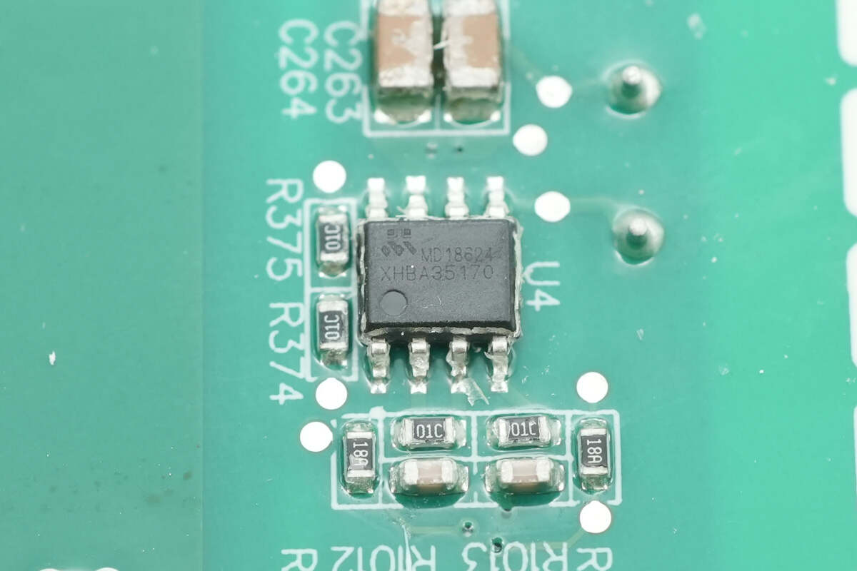
The driver used to drive the isolation transformer is a Meraki MD18624.
The other drive is the same model.
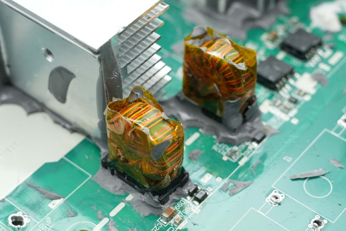
These two isolation transformers are used to drive LLC MOSFETs. They are wound with insulated wire and insulated with high-temperature tape.
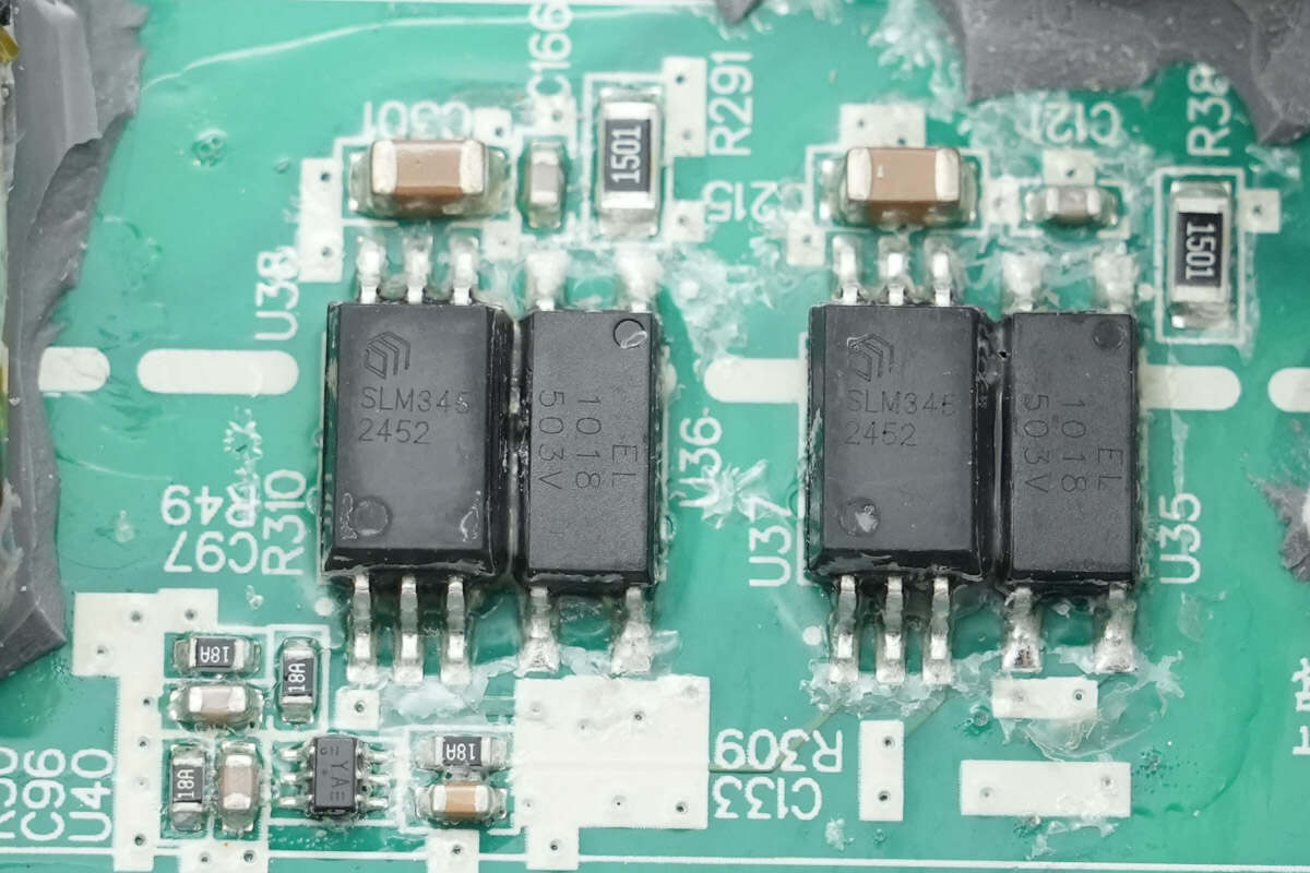
The isolation driver is from SiLLUMIN, model SLM345, which is a single-channel gate driver with 5kVrms isolation capability, 1A drive current, and an SOP6W package.
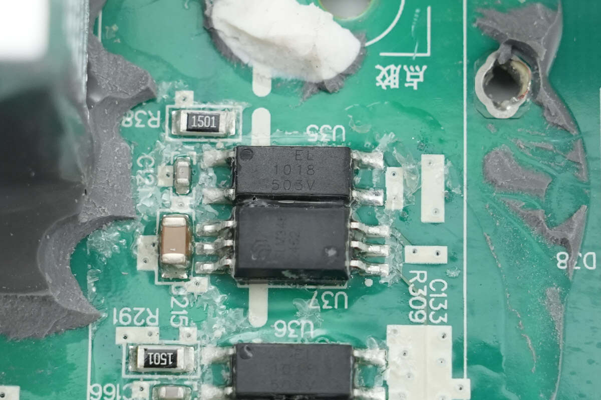
Close-up of Everlight EL1018 isolated optocoupler.
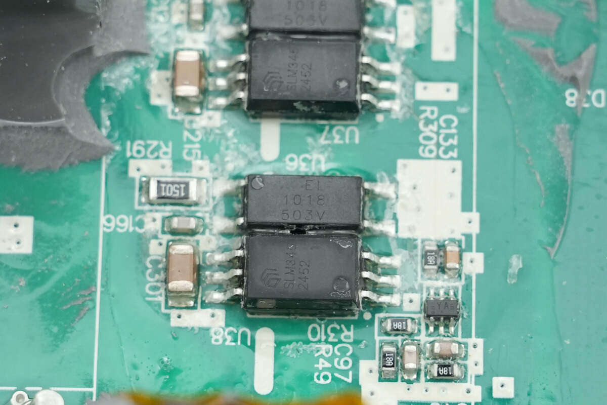
The other isolation optocoupler is of the same model.
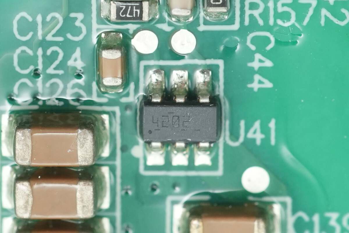
The buck chip is from TI, marked with 4202, model TPS54202. It is a synchronous buck converter with a 4.5-28V input voltage and a 2A output current, packaged in SOT23.
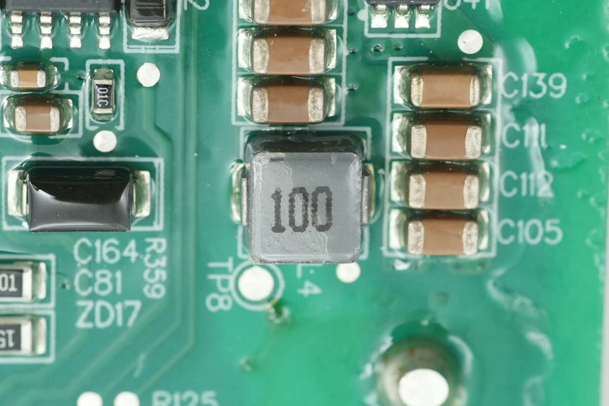
Close-up of the 10μH buck inductor used in conjunction with the device.
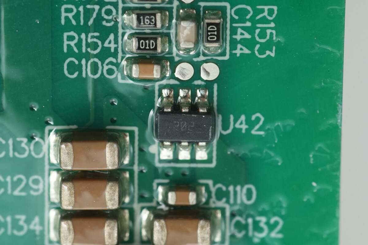
The other buck chip also uses the TI TPS54202.

Close-up of the 10μH buck inductor used in conjunction with the device.
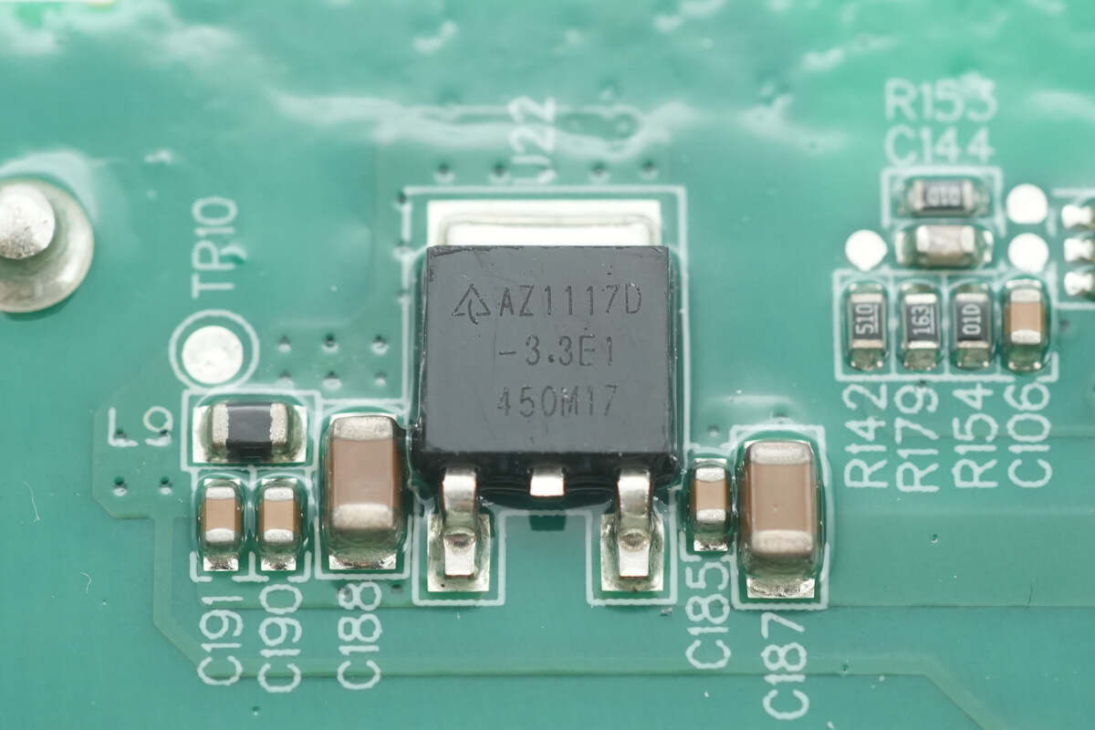
The regulator chip is from DIODES, model AZ1117D-3.3TRE1.
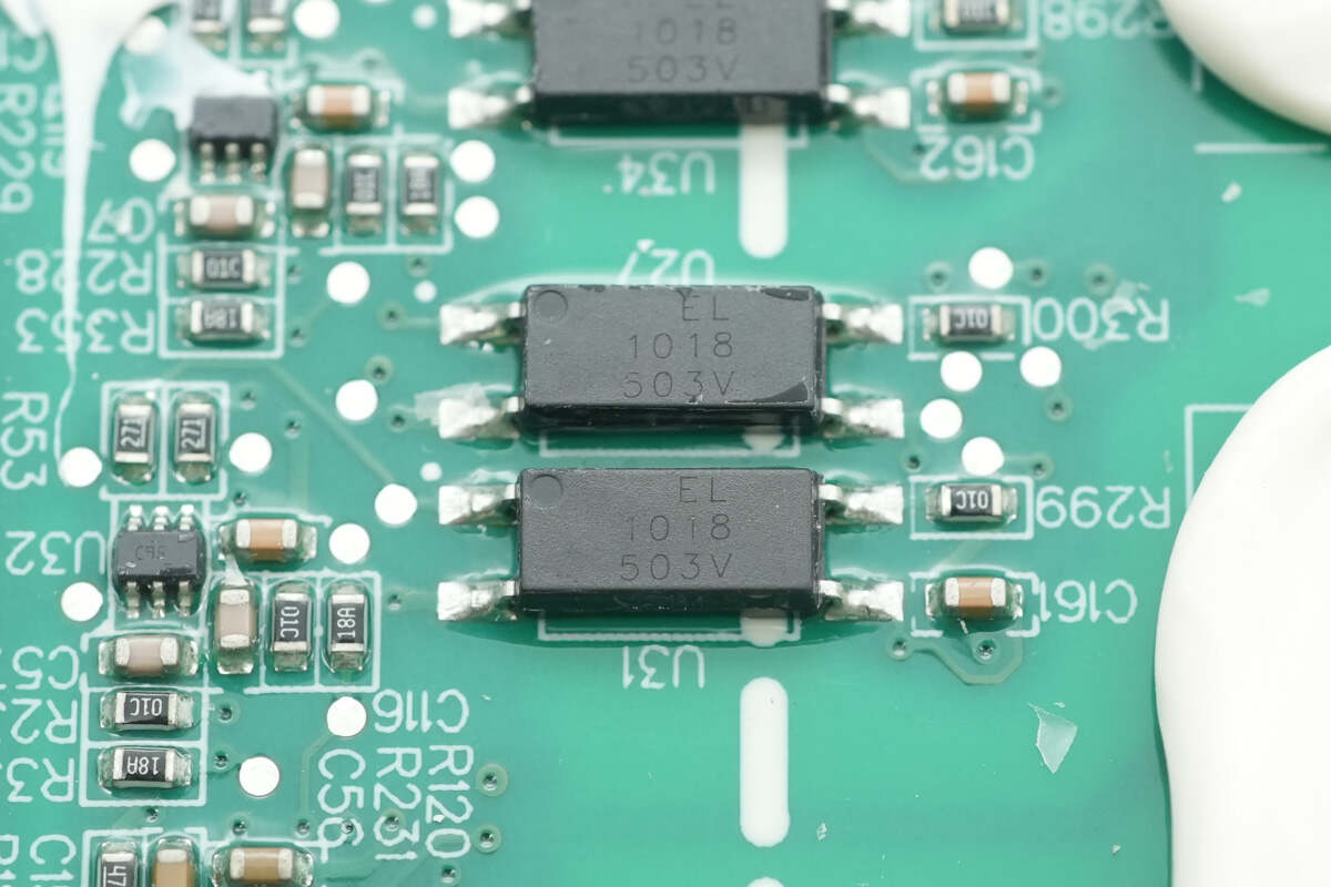
Close-up of Everlight EL1018 isolated optocouplers.
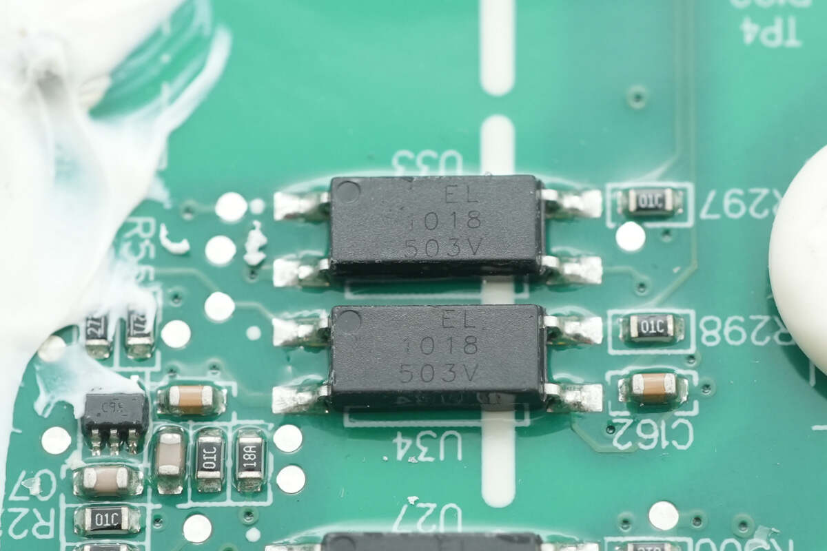
The other two isolation optocouplers are of the same model.
The relays are driven by Meraki MD18624 drivers, with a total of four used for relay switching, two of which are grouped. To save space, we will not go into details.
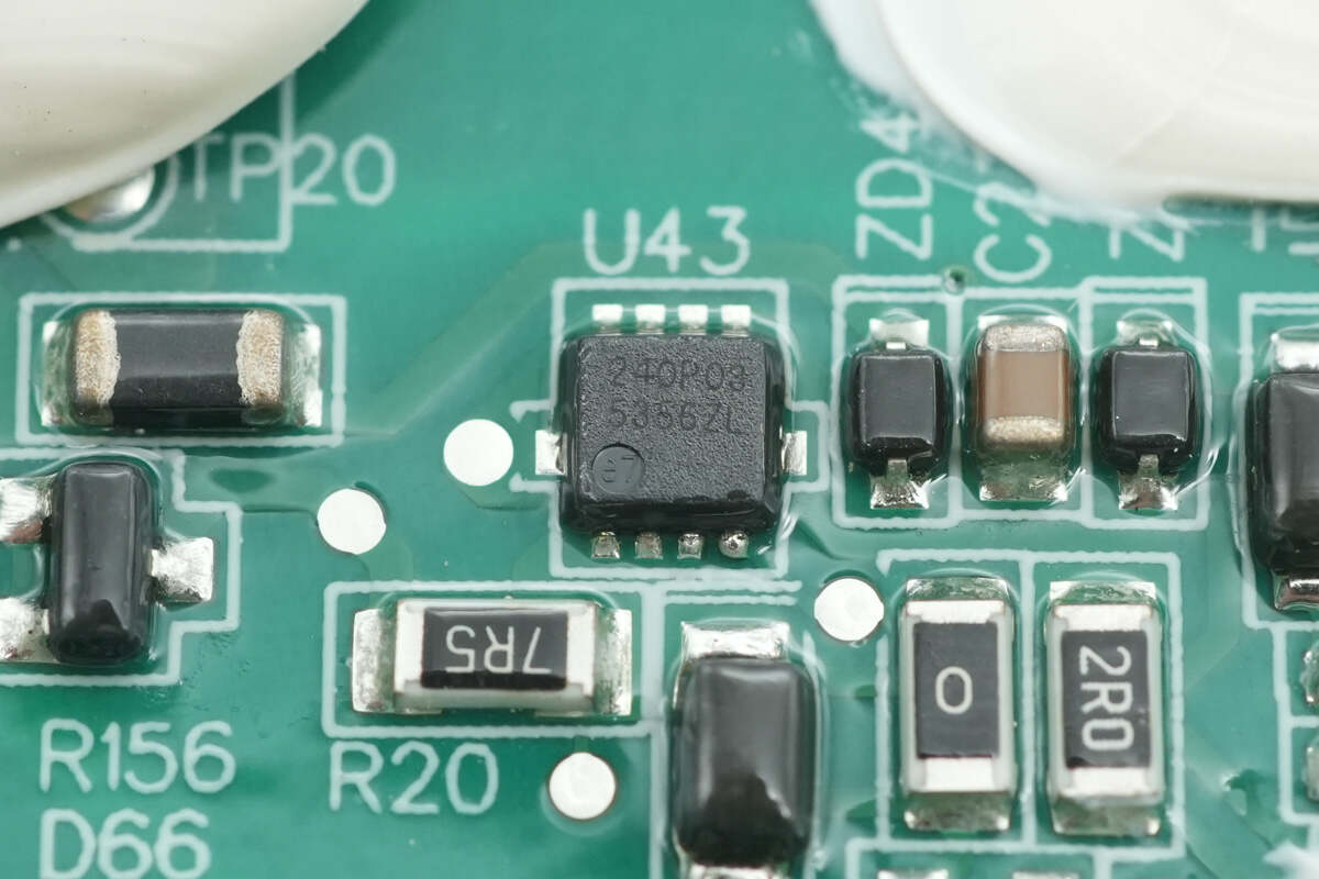
The MOSFET used for gate drive of SiC MOSFETs is from ZMJSEMI, model ZM240P03M, PMOS, with a voltage rating of -30V, an on-resistance of 24mΩ, and a DFN3*3 package.
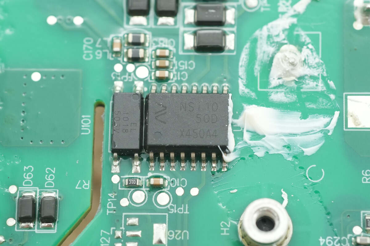
The isolated CAN transceiver is from NOVOSENSE, model NSi1050, compliant with ISO11898-2 standard, supports 5kVrms insulation withstand voltage, has a data transmission rate of 1Mbps, and is packaged in SOW16.
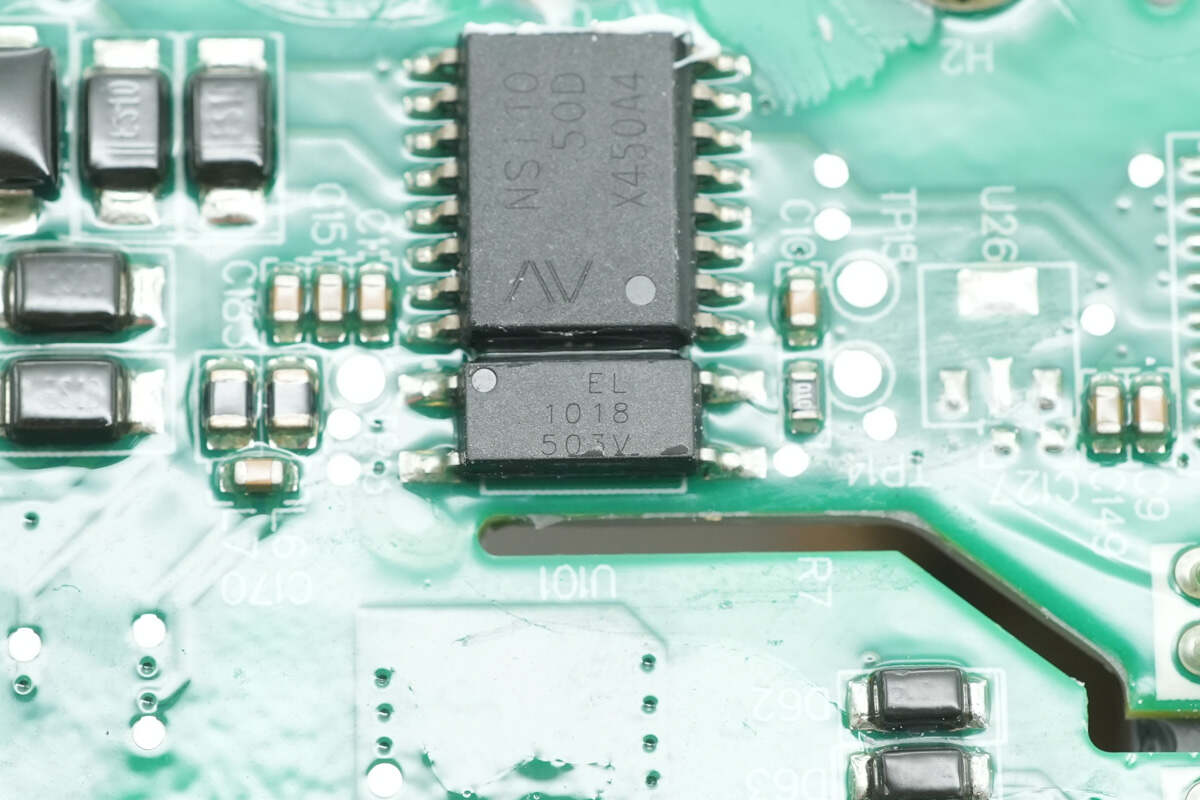
The isolation optocoupler used is Everlight EL1018.
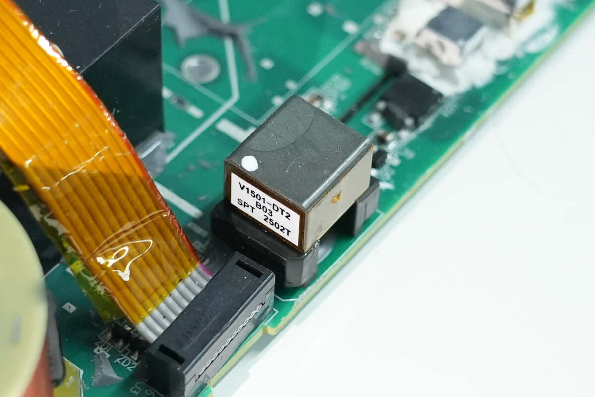
Close-up of the isolation power supply transformer.
The regulator chip is from DIODES, model AZ1117D-5.0RE1.

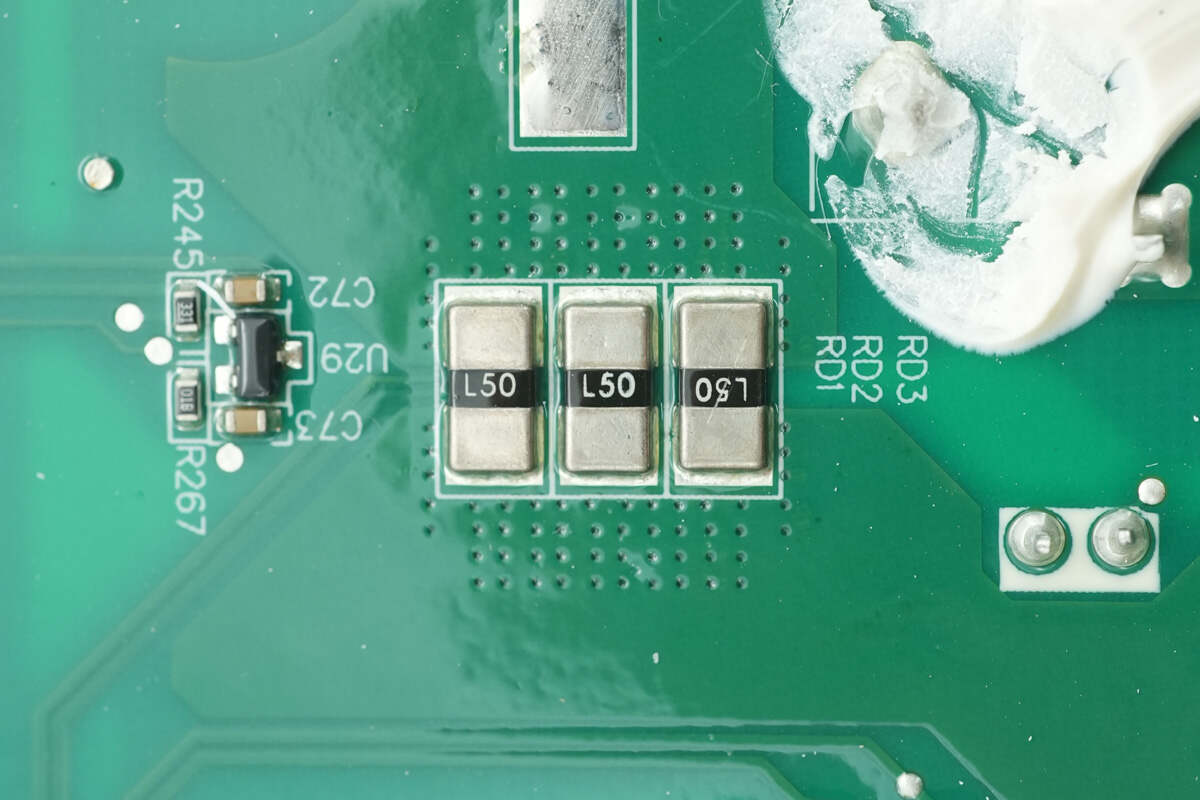
Close-up of three filter inductors.
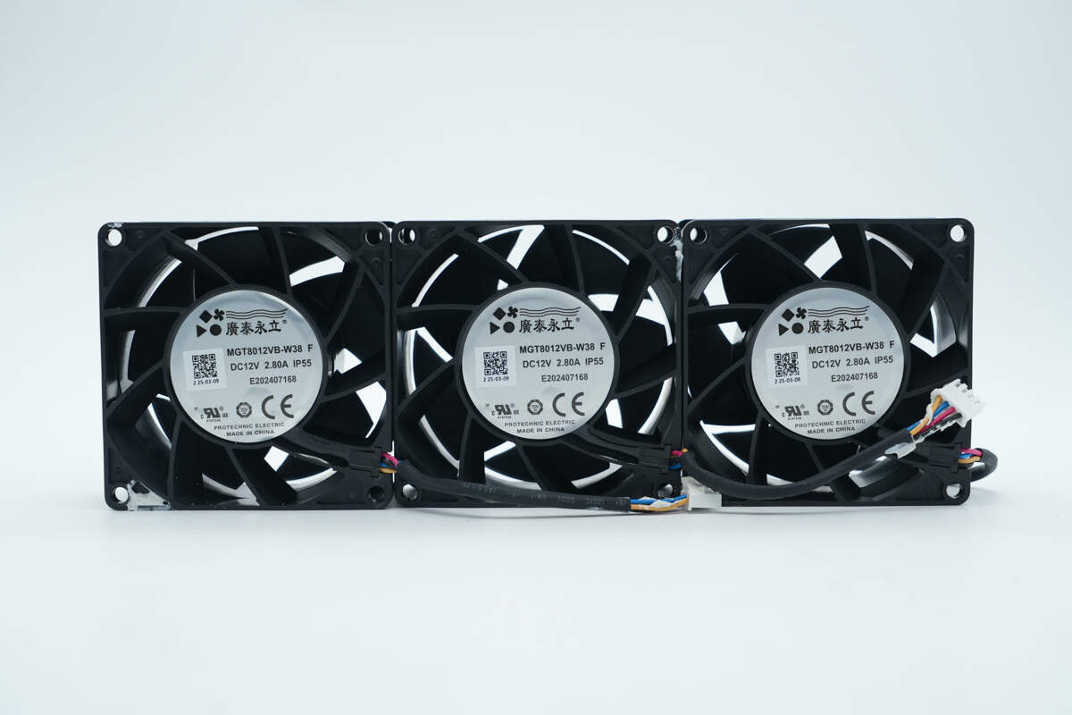
Close-up of the three cooling fans.
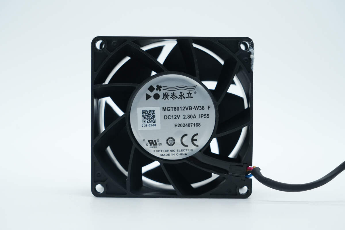
The cooling fan, model MGT8012VB-W38, is rated for DC12V 2.8A and has IP55 protection capability.
Well, those are all components of the Infypower 40kW EV SiC Power Module.
Summary of ChargerLAB

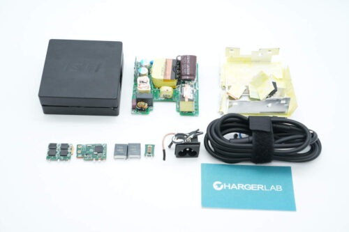
Here is the component list of the Infypower 40kW EV SiC Power Module for your convenience.
It features a three-phase AC input, supporting an input voltage range of 260–530 V, with a DC output voltage range of 150–1000 V and an output current of 133 A. The rated output power is 40 kW, making it suitable for electric vehicle charging across different voltage platforms. It is equipped with indicator lights, DIP switches, and cooling fans.
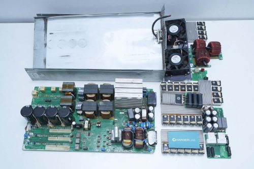
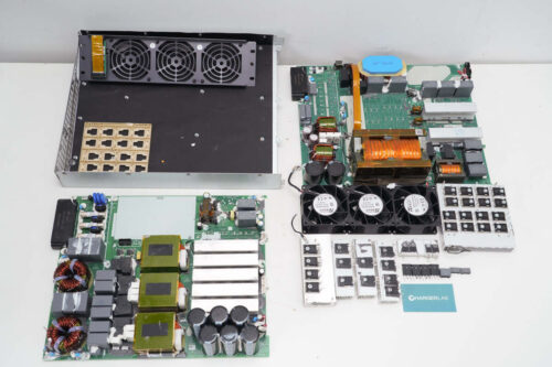
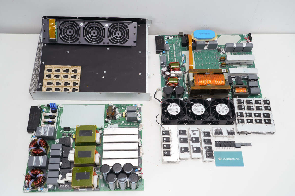
After taking it apart, we found that the PCBA module is composed of two stacked layers, consisting of a PFC module and an LLC module, connected via wiring. Both the PFC controller and the LLC controller use the TI TMS320F28035PAG, with input current detection performed through AMC1200B isolation chips. The PFC MOSFETs are Sanrise SRC60R022FBS, paired with Sanan SDS120J40H3 SiC diodes for rectification, and isolated via NOVOSENSE NSi6801BD drivers.
The LLC circuit uses APS ACM035P120QNN SiC MOSFETs, paired with ACD20PS120ANX and ACD40PD120AN SiC diodes for rectification. Meraki MD18624 and drivers are used for driving the PFC MOSFETs, LLC MOSFETs, and relays. The capacitors are from JD and Jianghai. The PCBA module is manufactured using an encapsulation process, with a conformal coating applied on the back side, effectively enhancing product reliability and ensuring long service life.
Related Articles:
1. Teardown of Delta 550W SiC Server Power Supply (DPS-550AB-2)
2. Teardown of ASUS Adol 100W GaN Quick Charger (ADOL AC100-050A)
3. Teardown of CUKTECH 15 Charging Station (TA1406U)