Introduction
Previously, UGREEN released several NAS private cloud products, including the DXP 6800Pro and the DXP 8800 series. To address the risk of data corruption caused by unexpected power outages with these devices, the company specifically developed a 120W DC UPS.
This UPS features a built-in 12,000mAh lithium battery, capable of providing up to 10 minutes of emergency power supply. Its unique DC direct-output architecture eliminates the traditional AC/DC conversion stage found in conventional UPS systems. Compact in size and weighing only 441 grams, it is designed for both efficiency and portability. Next, let’s take it apart to see its internal components and structure.
Product Appearance
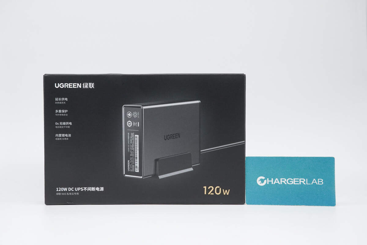
The front of the packaging features the UGREEN logo, name, a visual of the device, and key selling points.
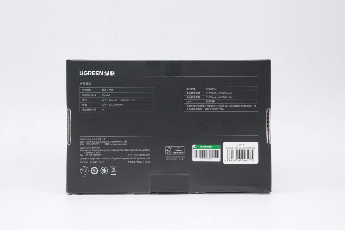
The bottom of the packaging displays the product specifications along with manufacturer and vendor information.
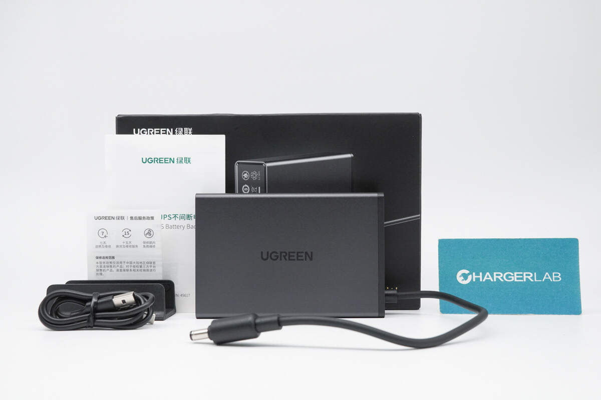
The package includes the UGREEN 120W DC UPS, a base stand, a data cable, and some documentation.
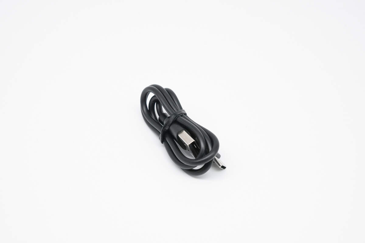
The included cable is a USB-A to USB-C type.
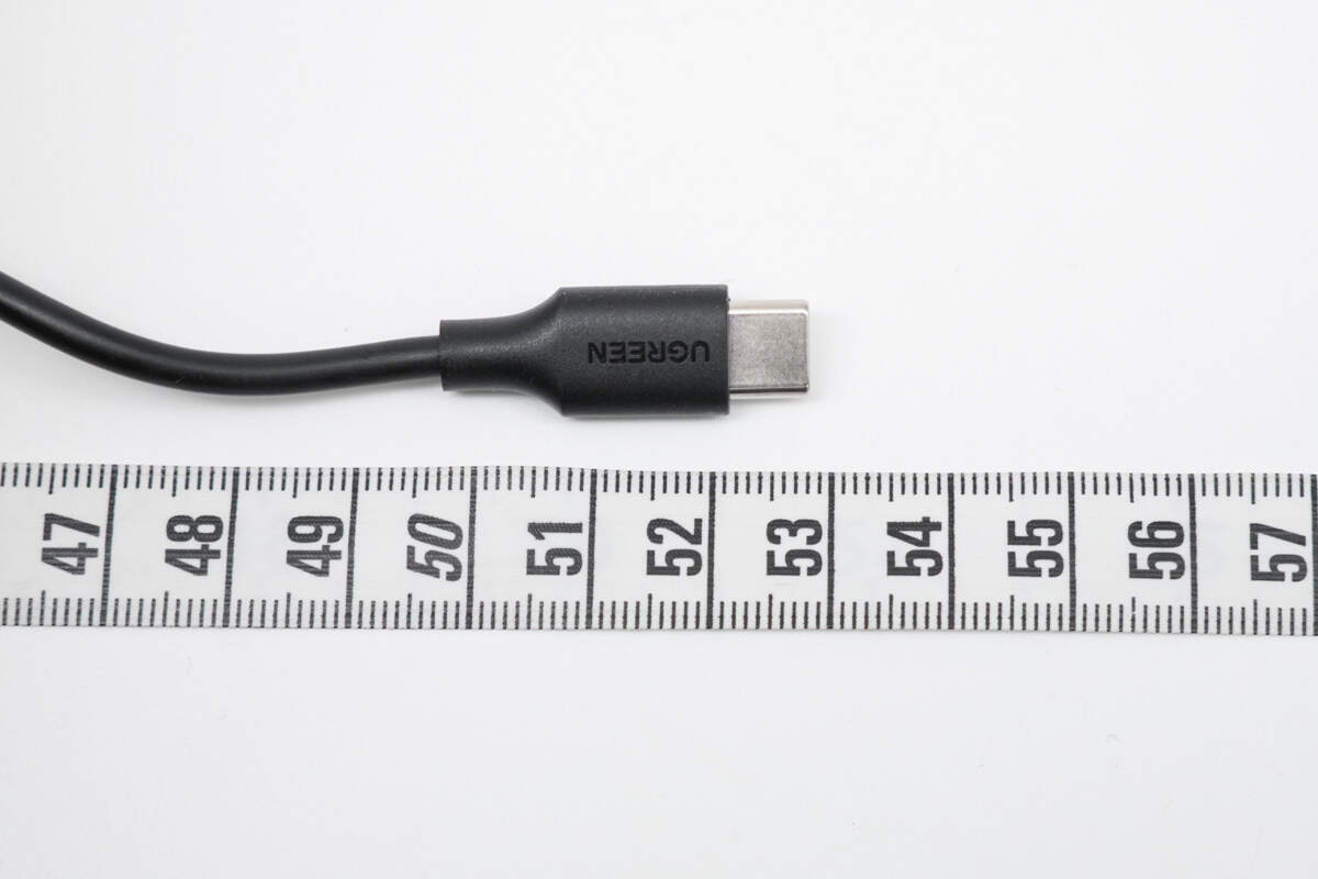
The length of the cable is about 53 cm (20.87 inches).
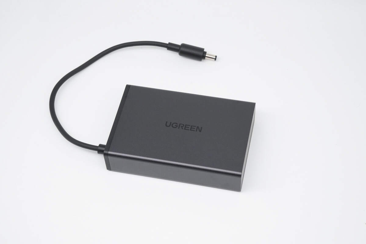
It comes with a built-in DC power cable. The surface features anodizing and sandblasting treatments, giving it a premium and refined texture.
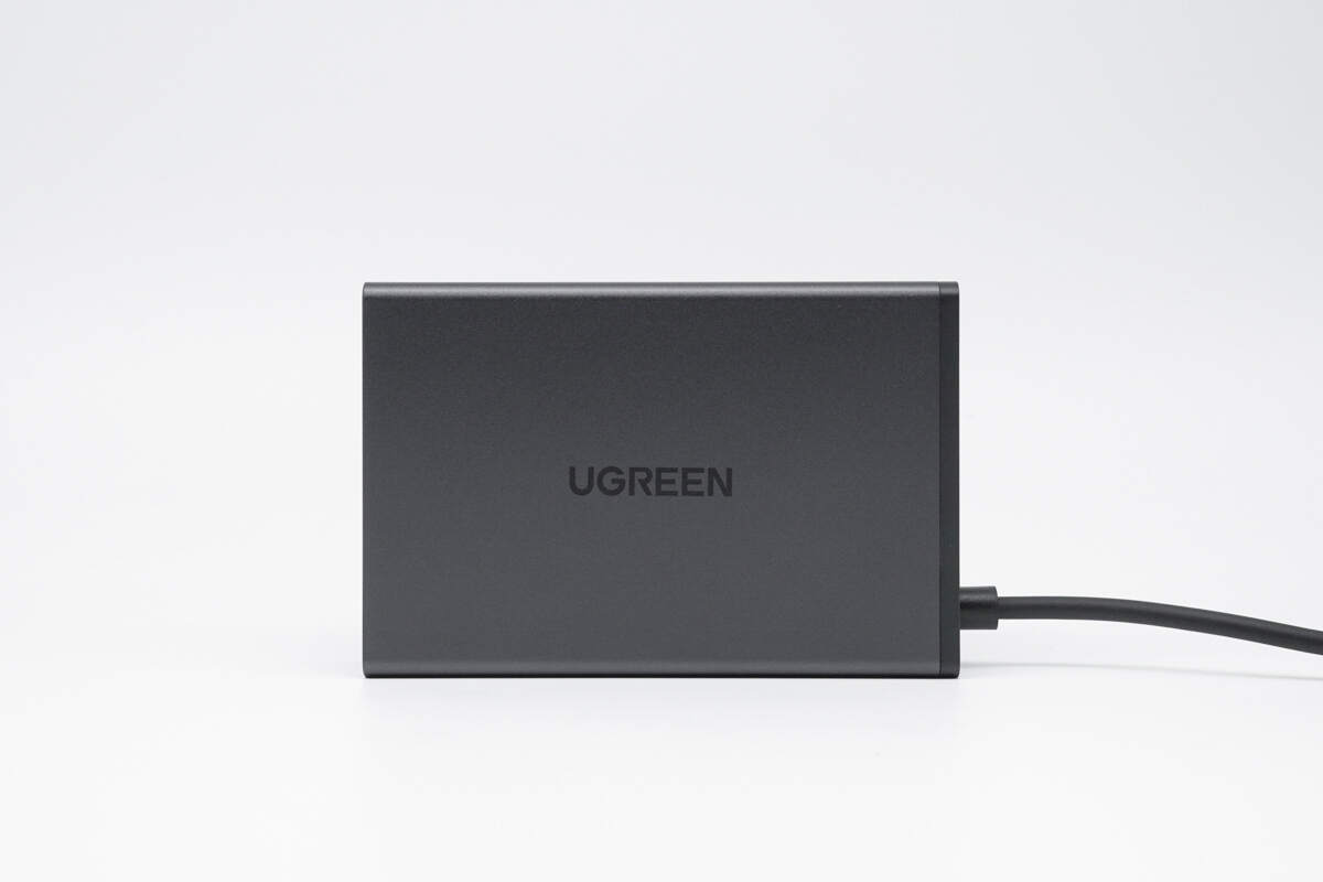
The UGREEN logo is prominently printed at the center of both the front and back sides.
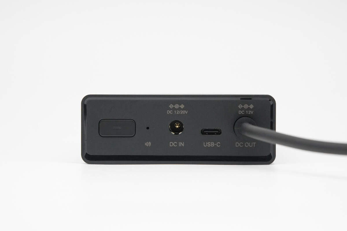
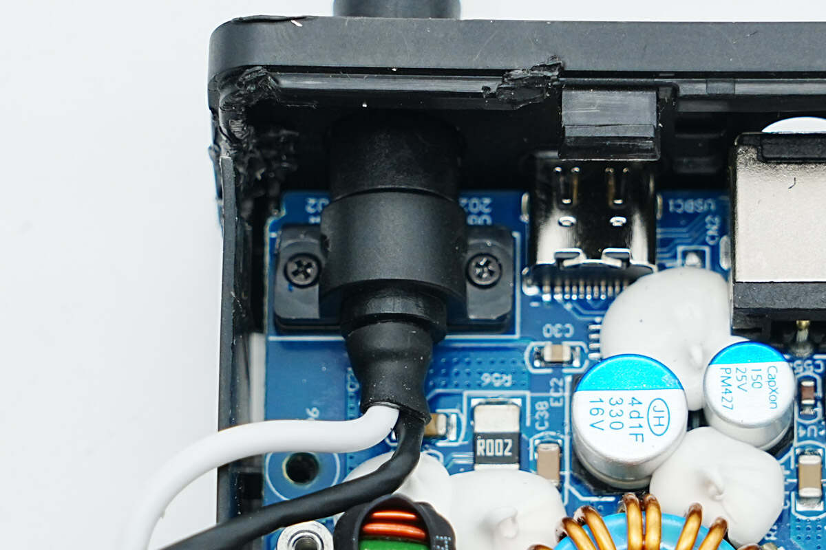
On the same end as the DC power cable, you'll also find a power button, a buzzer, a DC input port, and a USB-C port.
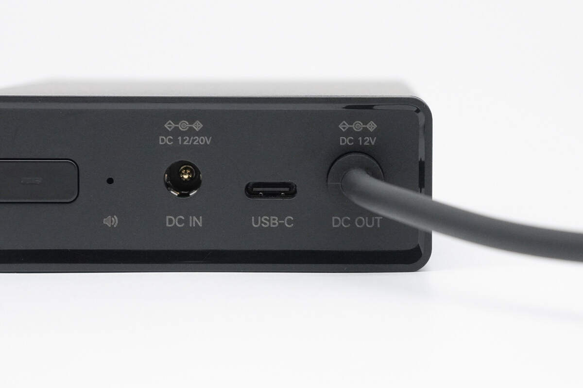
Each port and button is clearly labeled with corresponding icons and specifications for easy identification.
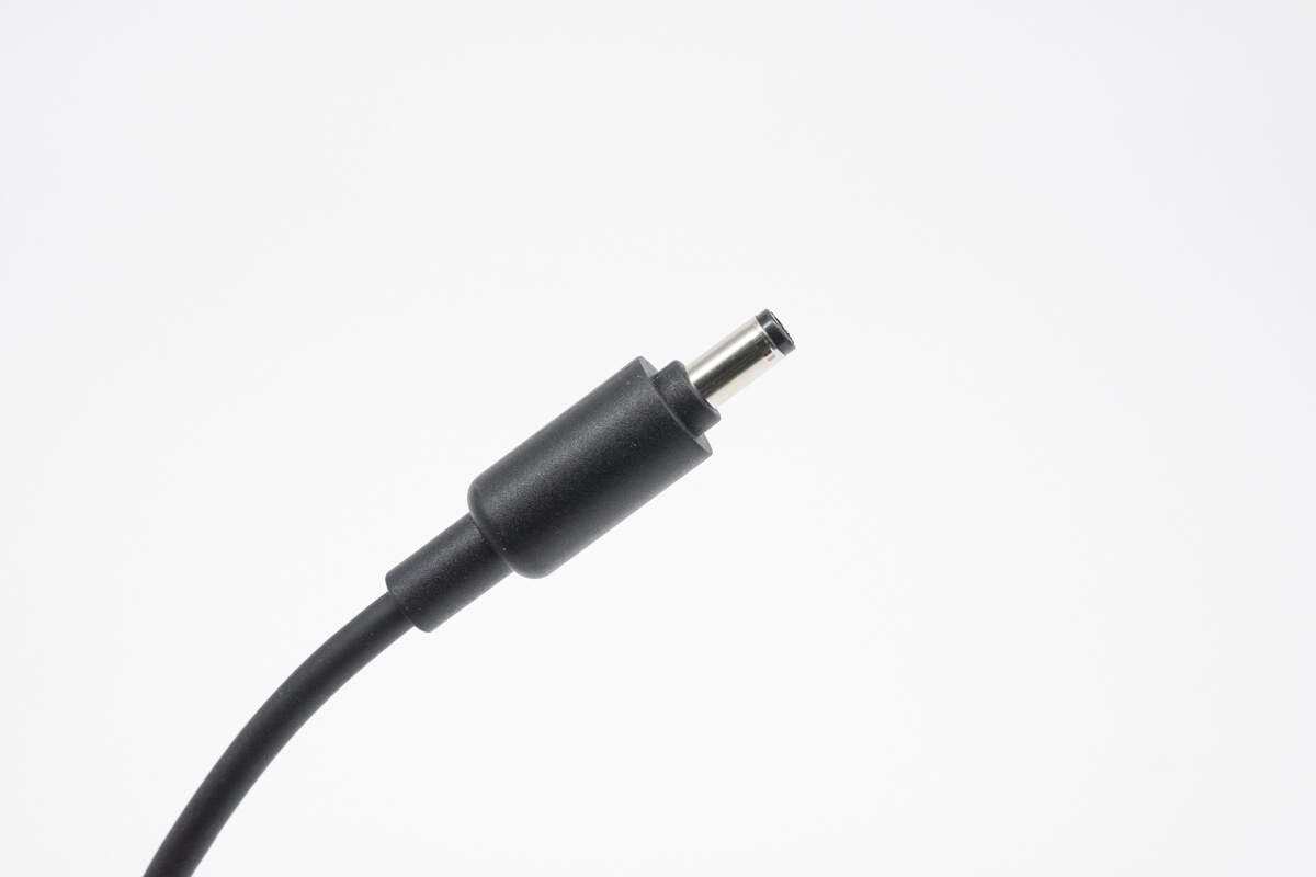
Close-up view of the DC power cable connector.
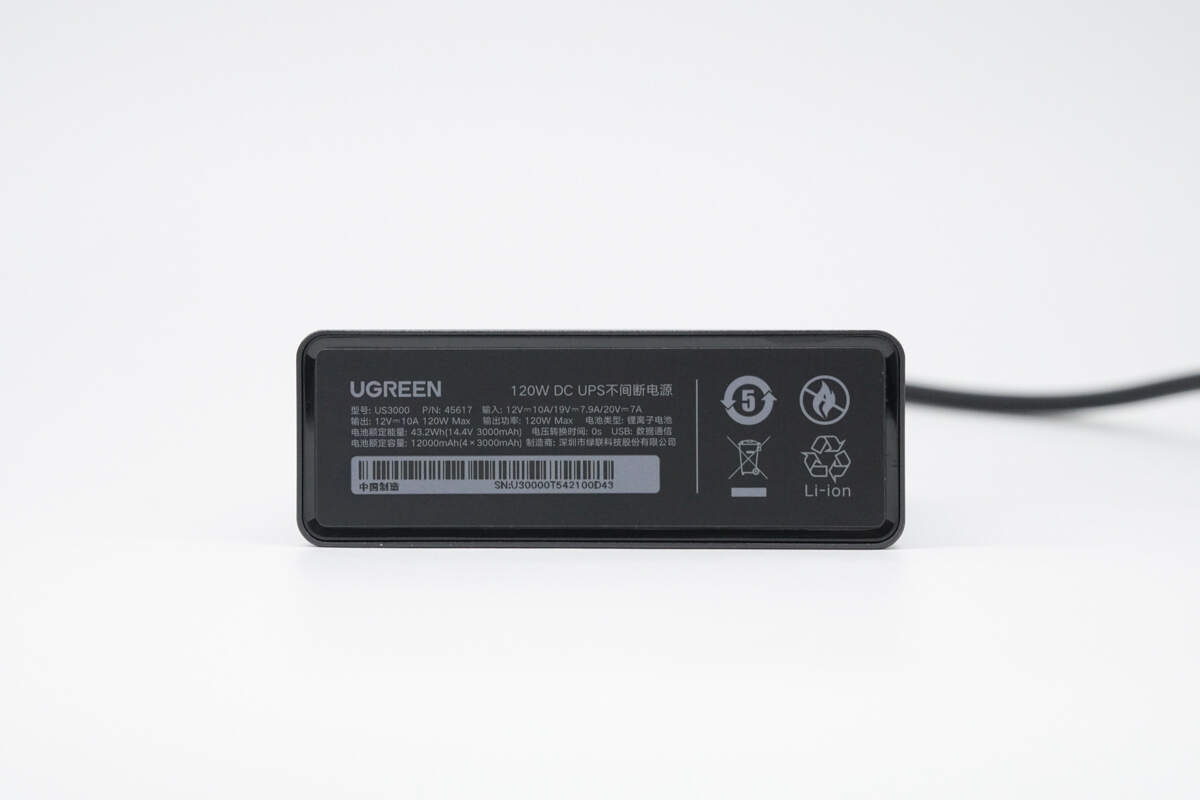
The other end is affixed with a nameplate.
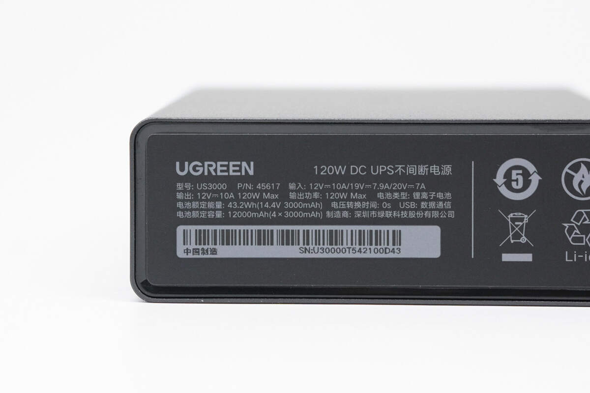
Model: US3000
Input: 12V 10A, 19V 7.9A, 20V 7A
Output: 12V 10A, 120W Max
Output Power: 120W Max
Battery Type: Lithium-ion Battery
Battery Rated Energy: 43.2Wh (14.4V 3000mAh)
Battery Rated Capacity: 12,000mAh (4 x 3000mAh)
Voltage Transfer Time: 0s
USB: Data Communication
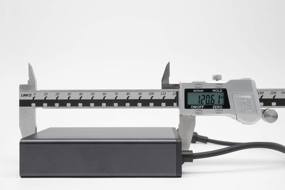
The length is about 120.61 mm (4.75 inches).
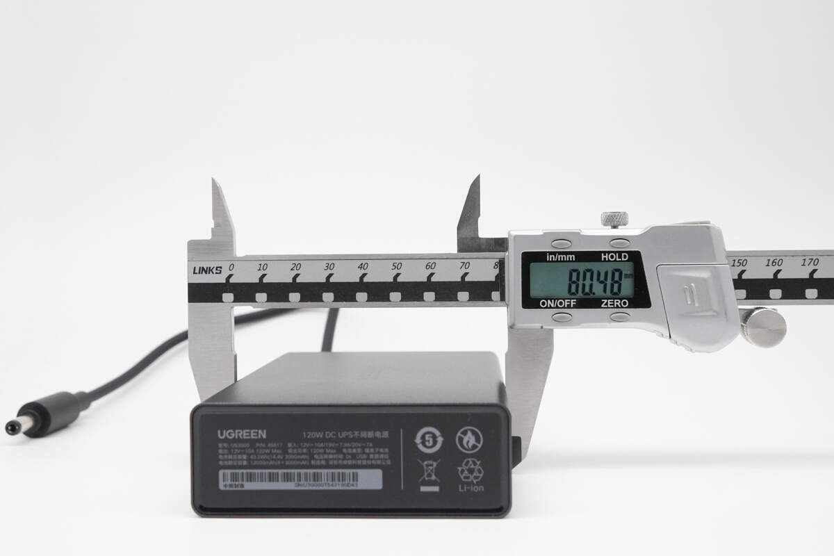
The width is about 80.48 mm (3.17 inches).
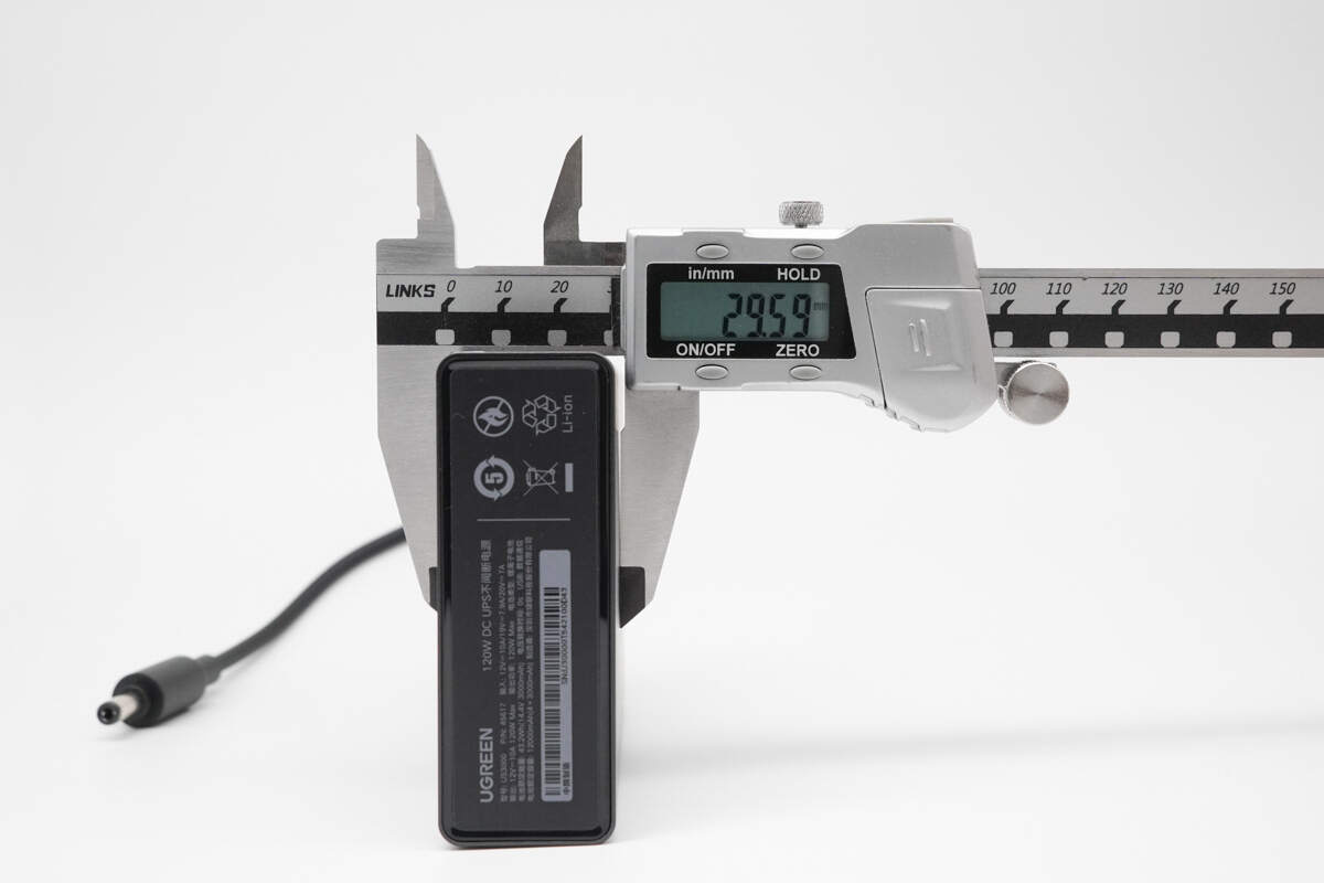
The thickness is about 29.59 mm (1.16 inches).
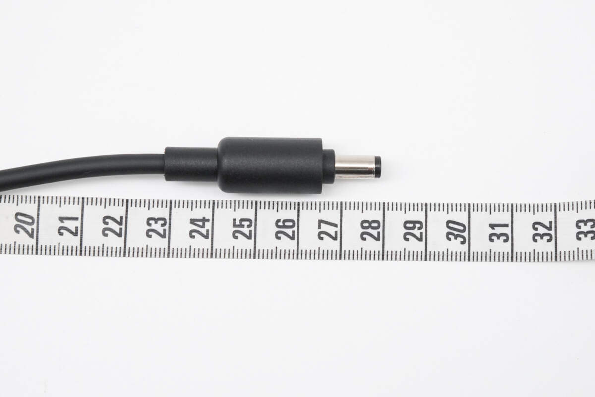
The length of the cable is about 28 cm (11.024 inches).
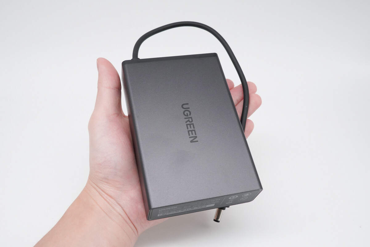
That's how big it is in the hand.
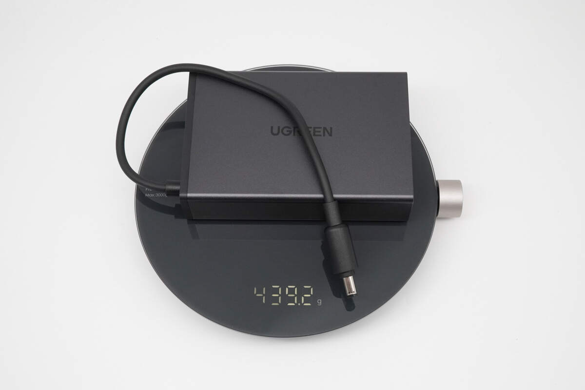
The weight is about 439 g (15.49 oz).
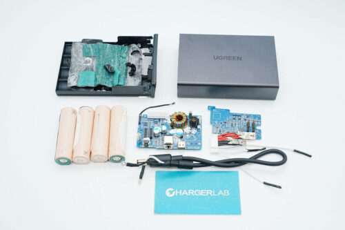
Teardown
Next, let's take it apart to see its internal components and structure.
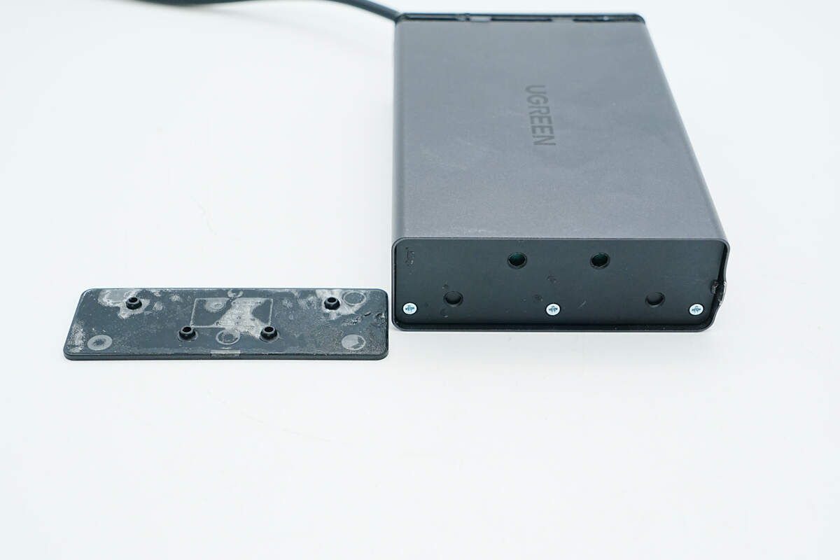
After removing the casing on one end, the internal mounting screws are revealed.
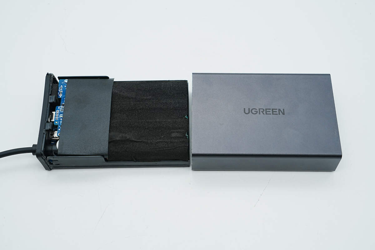
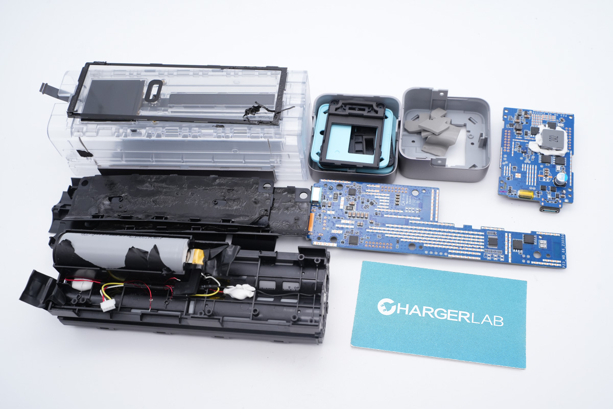
Once the screws are removed, the internal module can be slid out. The other end is secured with clips.
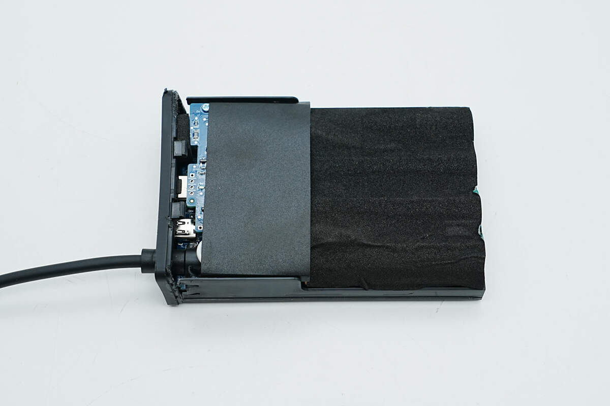
The module is housed within a protective plastic frame. The PCB is covered with a Mylar sheet, while the battery cells are wrapped in foam for added cushioning and protection.
Remove the Mylar sheet and foam. There is highland barley insulation paper on the inside of the foam.
The PCBA module adopts a dual-layer design, with the two layers secured together using metal standoffs and screws.
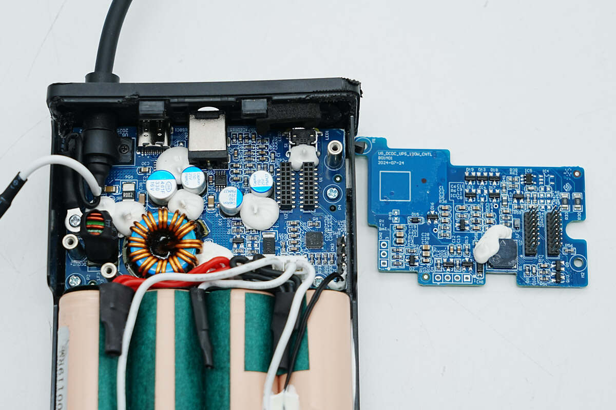
Remove the upper PCB.
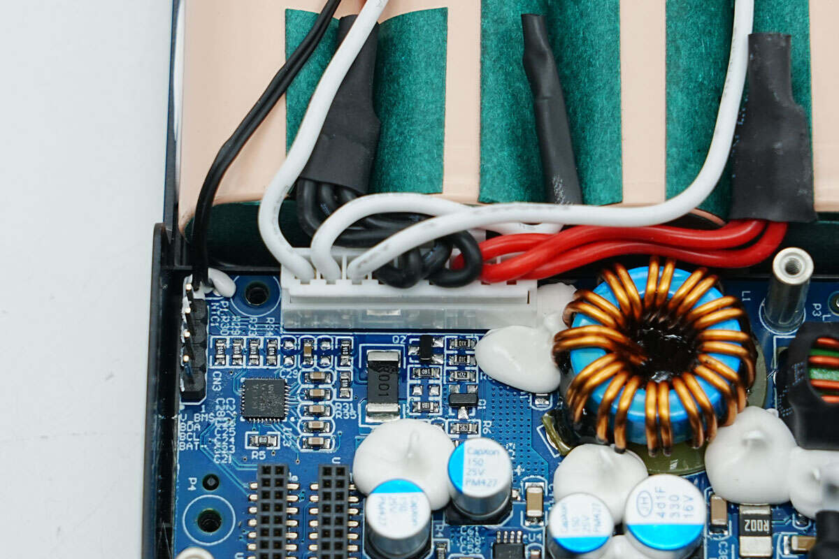
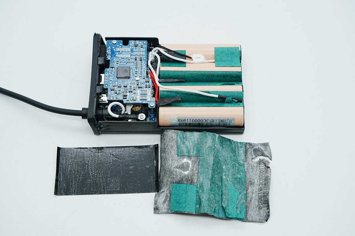
The battery pack is connected to the lower PCB via a pluggable wire connector.
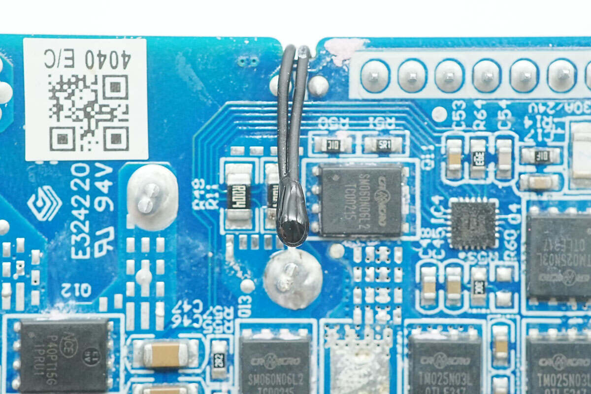
The DC power cord is reinforced internally.
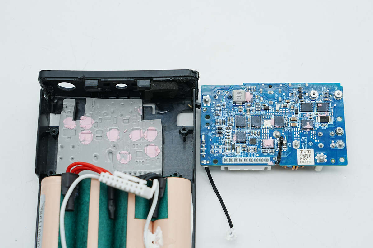
Remove the lower PCB. A thermal pad is placed in the slot.
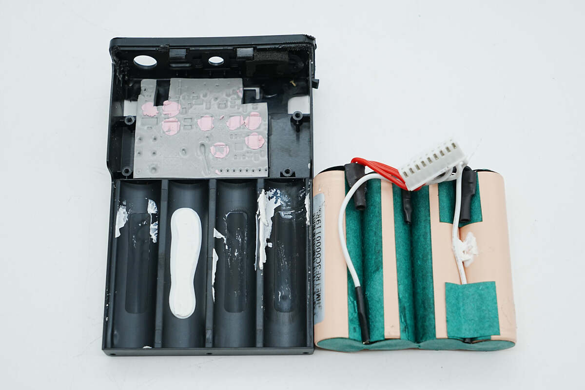
Remove the battery pack. Adhesive is applied in the slot for fixation.
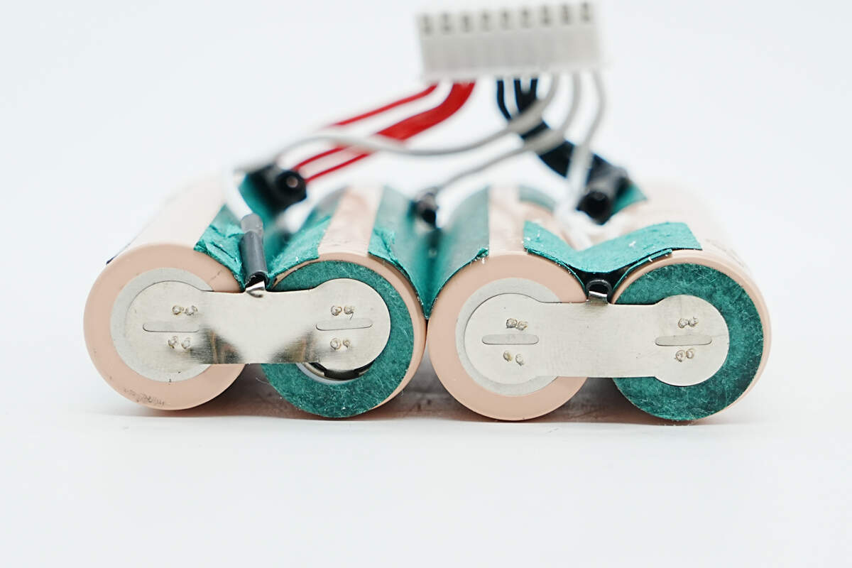
Barley paper is applied to the sides and positive terminals of the four battery cells in the pack. The cells are interconnected by spot-welded nickel strips.
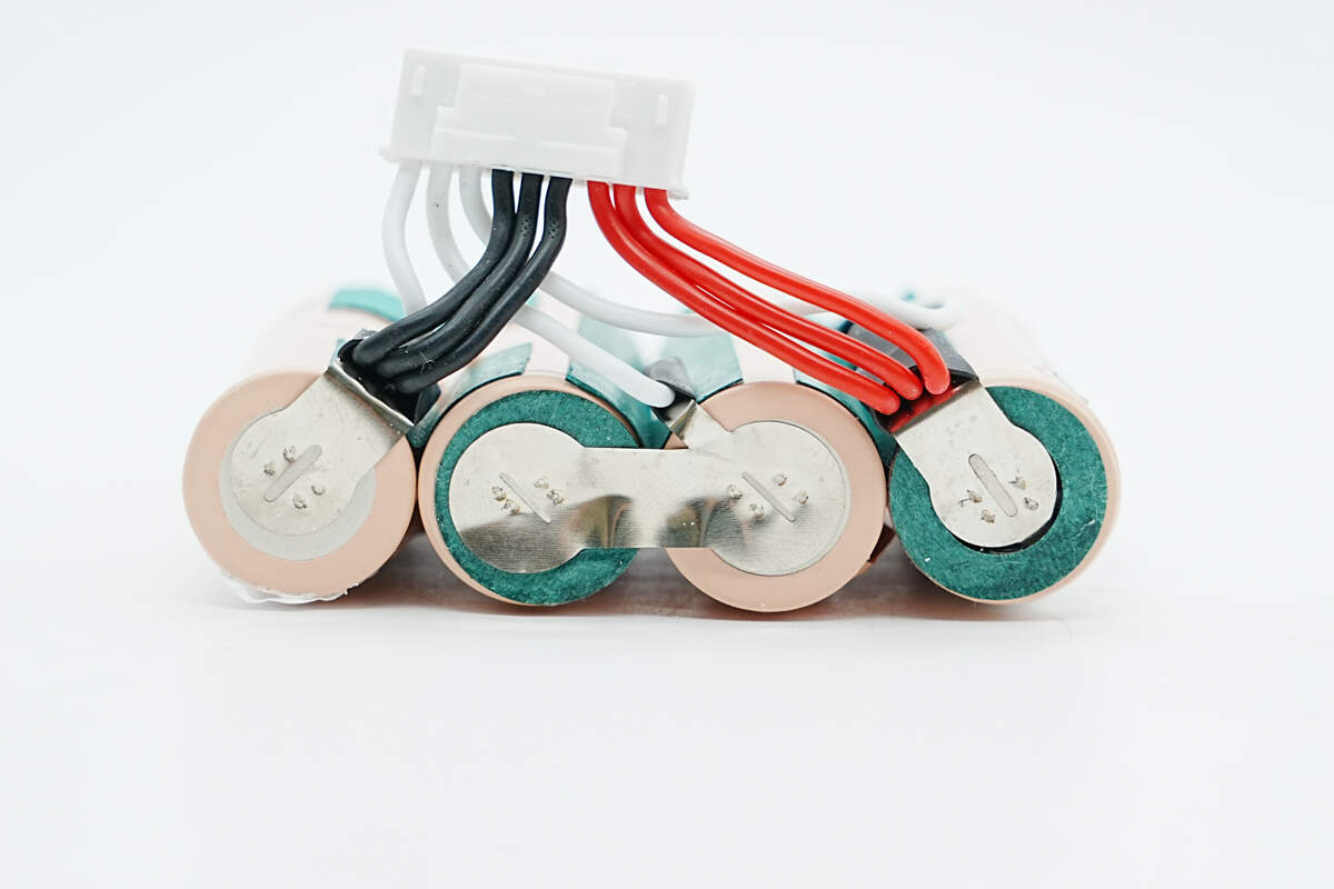
The nickel strips are soldered to the wires. Based on the spot-welding configuration at both ends of the four battery cells, it can be determined that the cells are connected in series.
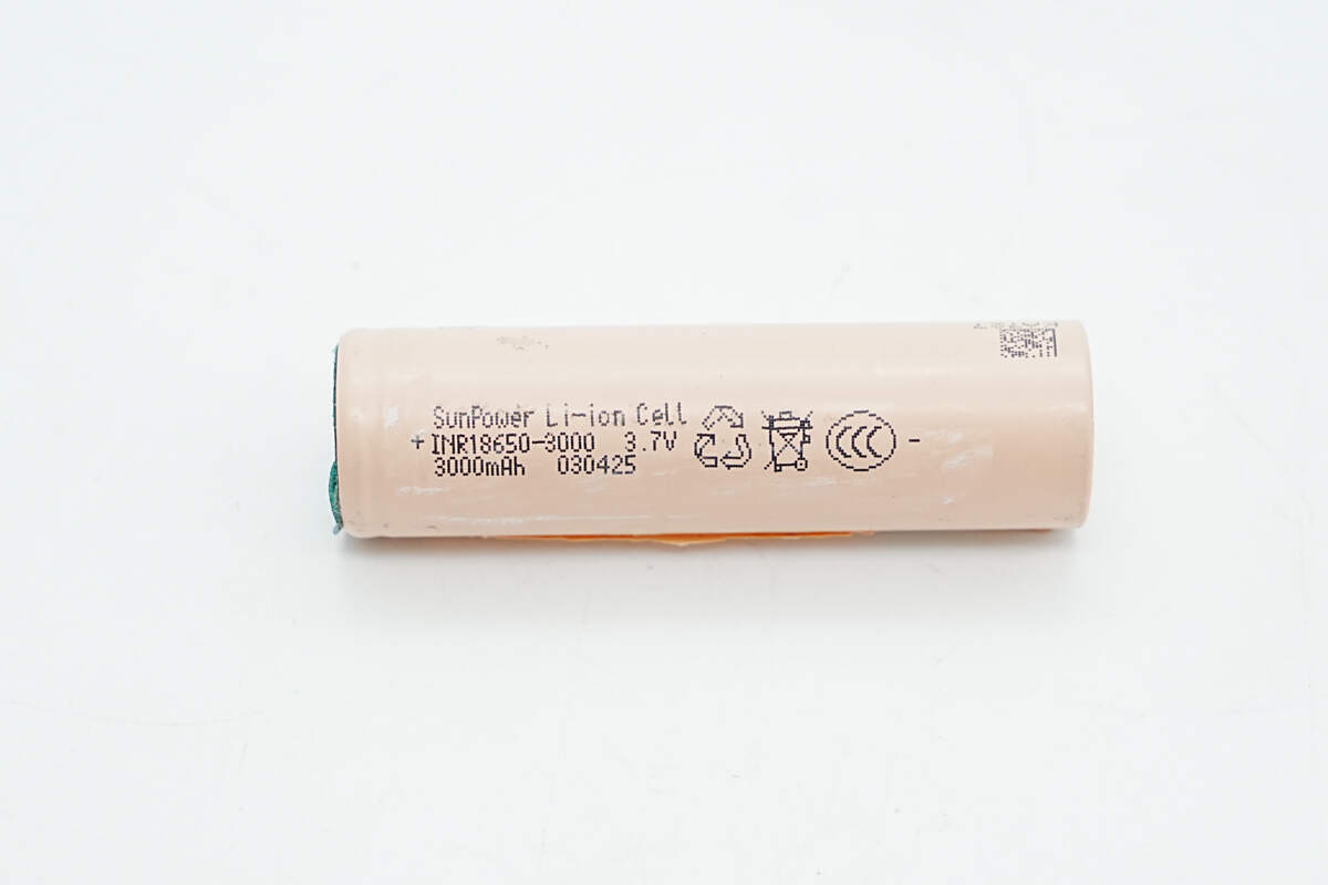
All four lithium batteries are SunPower INR18650-3000 cells, each with a capacity of 3000 mAh, a nominal voltage of 3.7 V, and an energy rating of 11.1 Wh. The cells are CCC certified.
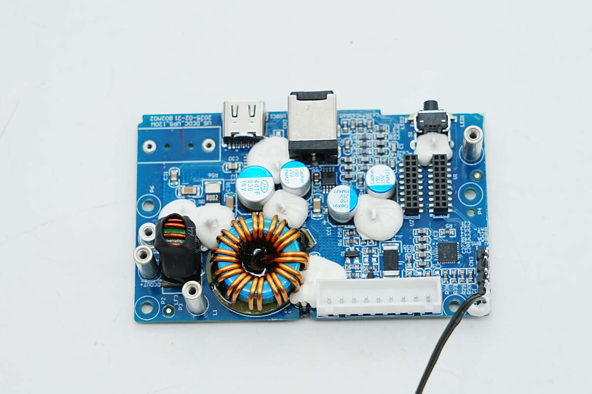
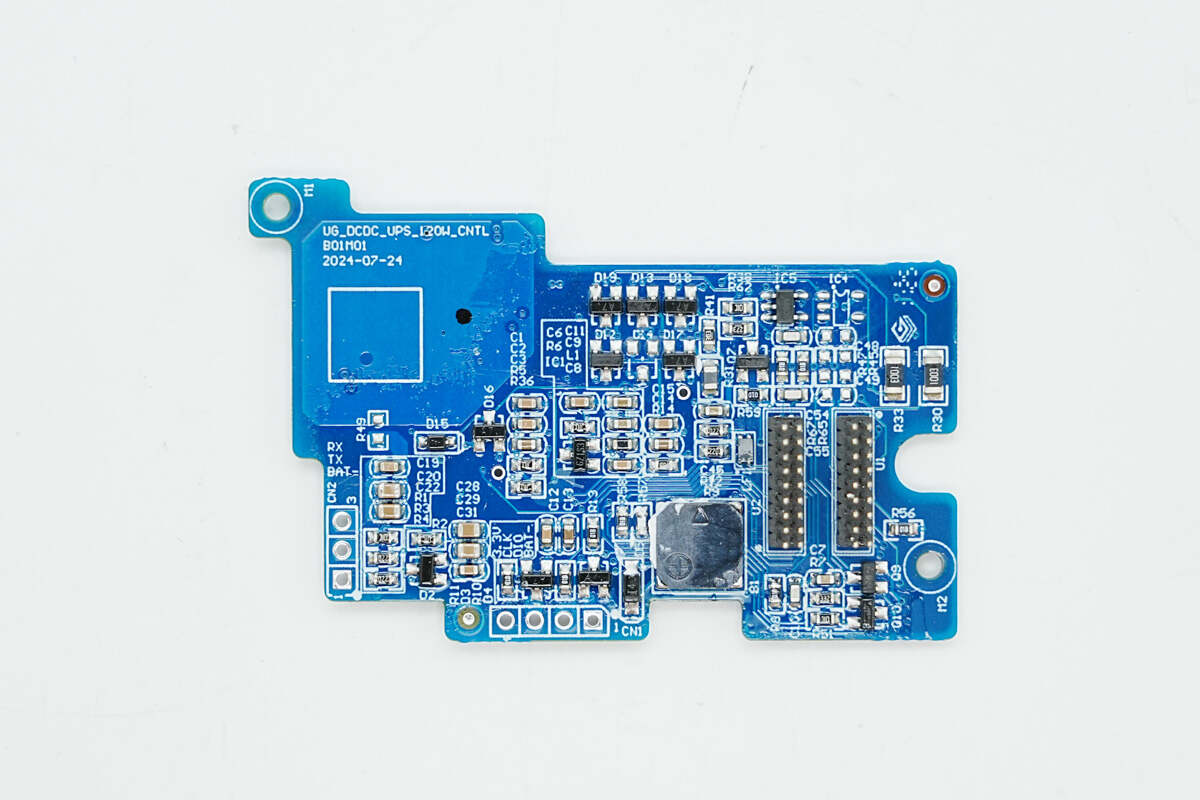
Capacitors, inductors, and other components on the front side of the lower PCB are reinforced with adhesive.
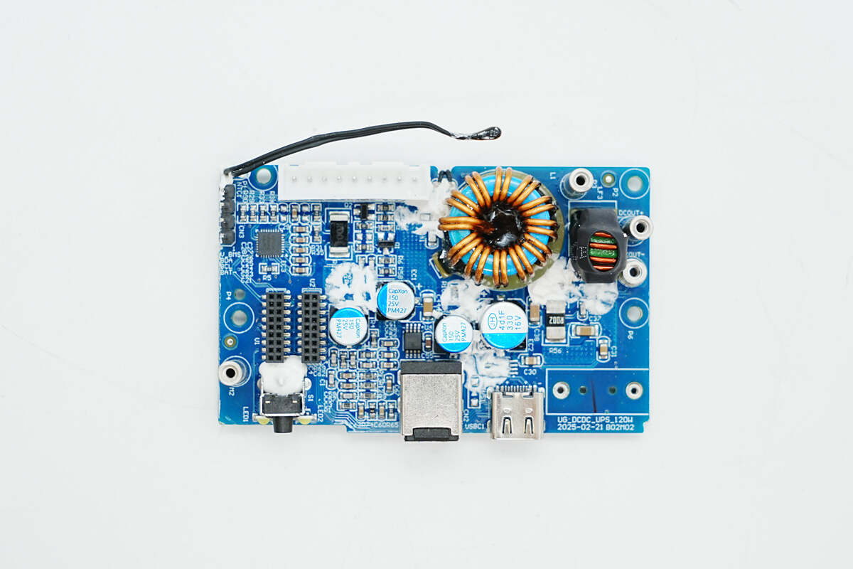
After removing the white adhesive, the front side reveals a battery protection chip, a buck inductor, filter capacitors, a thermistor, and other components.
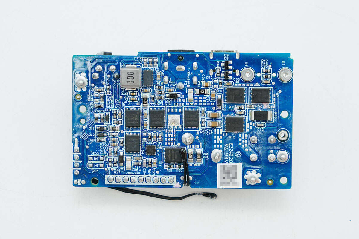
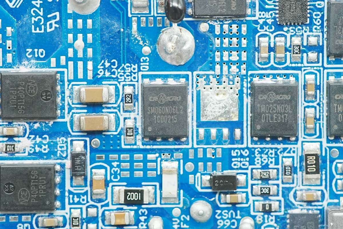
The backside contains a synchronous buck-boost converter, a synchronous buck controller, synchronous buck MOSFETs, and switching MOSFETs.
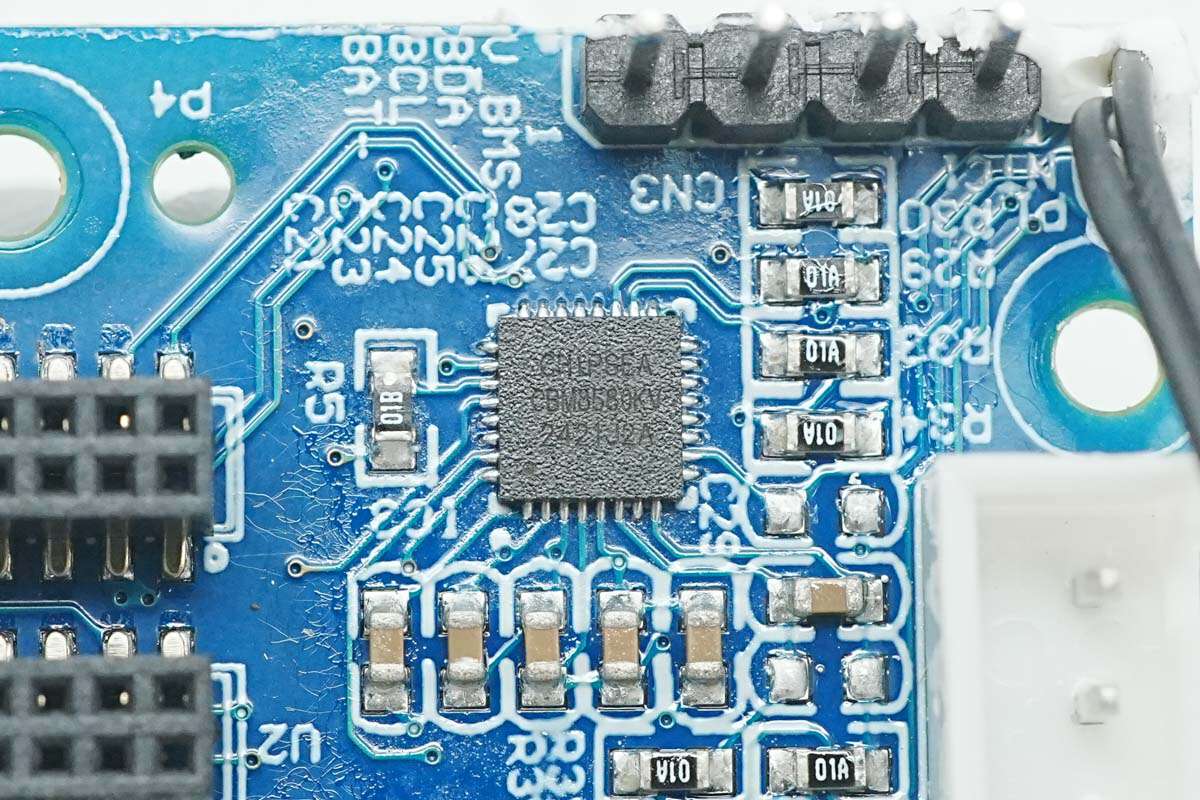
The battery protection chip is the CBM8580KV6NT from Chipsea. It is a fully integrated single-chip solution designed for 2-cell, 3-cell, and 4-cell series lithium-ion or lithium-polymer battery packs, offering comprehensive features for fuel gauging, protection, and authentication.
The CBM8580KV6NT utilizes its integrated high-performance analog peripherals to measure key parameters such as available capacity, voltage, current, and temperature of the lithium battery pack. It maintains accurate data logging and communicates this information to the system host controller via an SMBus 3.1-compatible interface.
Here is the information about Chipsea CBM8580KV6NT.
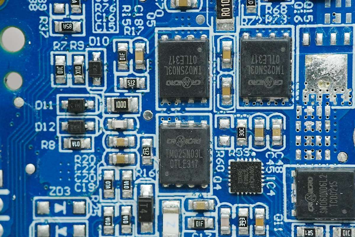
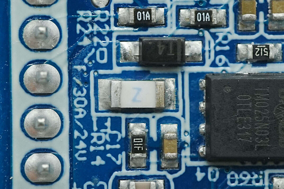
The battery protection MOSFETs are CRTM025N03L from CR MICRO. These are N-channel MOSFETs with a voltage rating of 30 V and a low on-resistance of 2.1 mΩ. They are packaged in a DFN5×6 form factor.
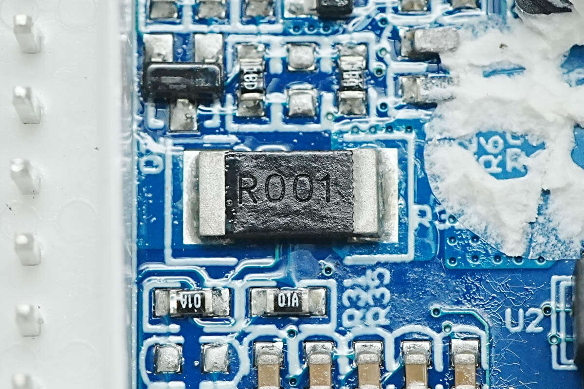
The current sense resistor has a resistance value of 1 mΩ.
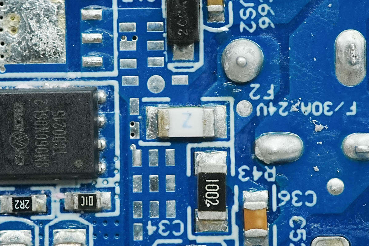
Close-up of the SMD fuse at the battery end.
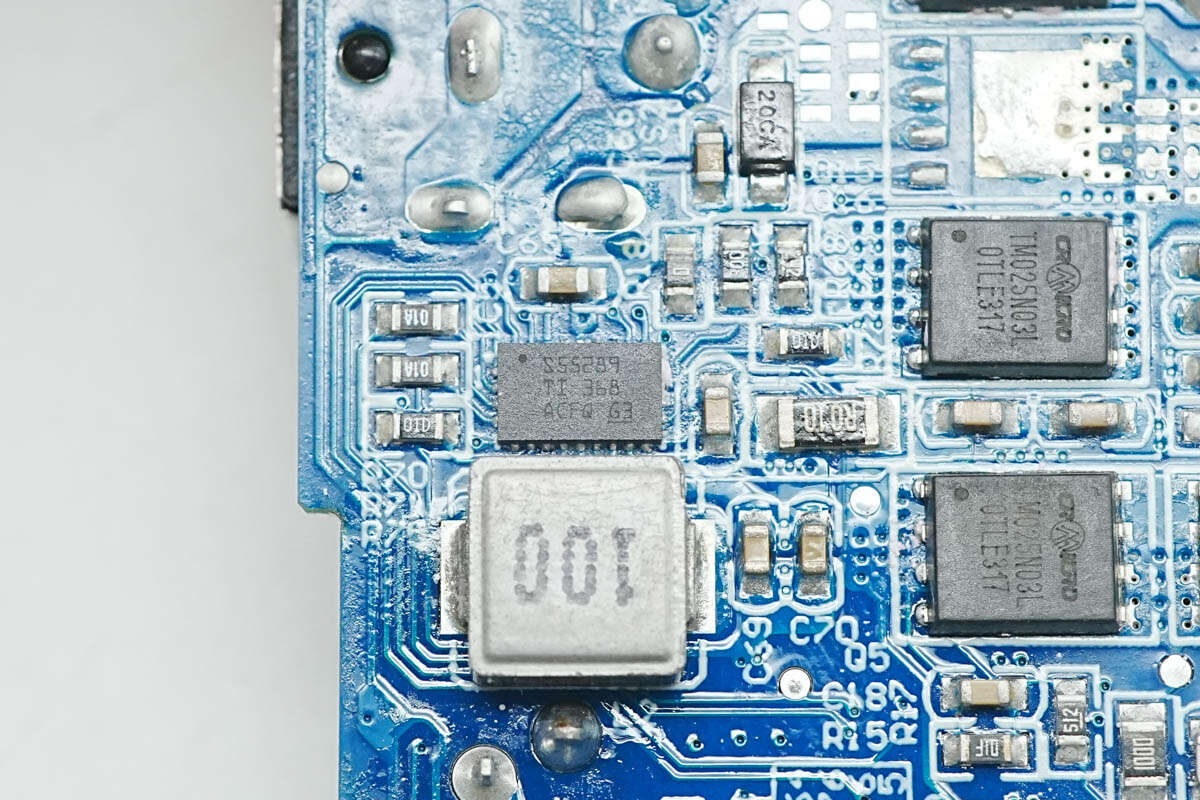
The synchronous buck-boost converter is the TI TPS55289. It supports input voltages up to 30 V and output voltages ranging from 0.8 V to 22 V. The device integrates four MOSFETs, providing a compact solution for USB PD applications. It is packaged in a VQFN-21 form factor.
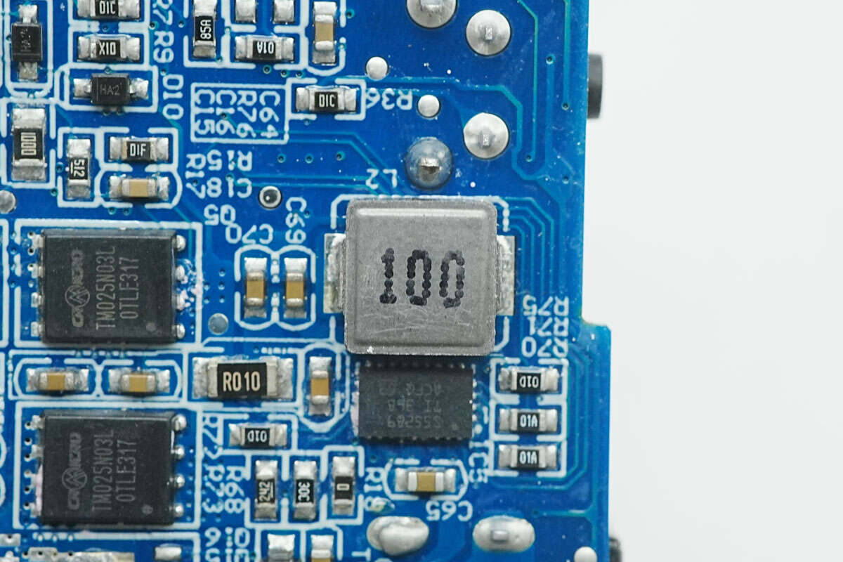
Close-up of the 10 μH buck-boost inductor used in conjunction with the converter.
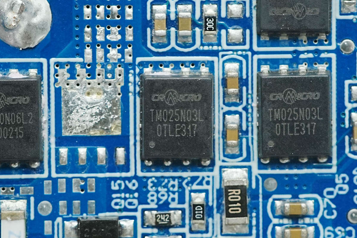
The MOSFET used for power control in the buck circuit is the CR MICRO CRTM025N03L.
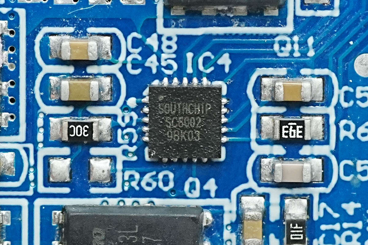
The synchronous buck controller is the SC8002 from SouthChip. It supports input voltages up to 36 V, features high-precision output current limiting, and supports independent current limiting for dual channels. It is suitable for applications such as car chargers, multi-port chargers, and USB hubs.
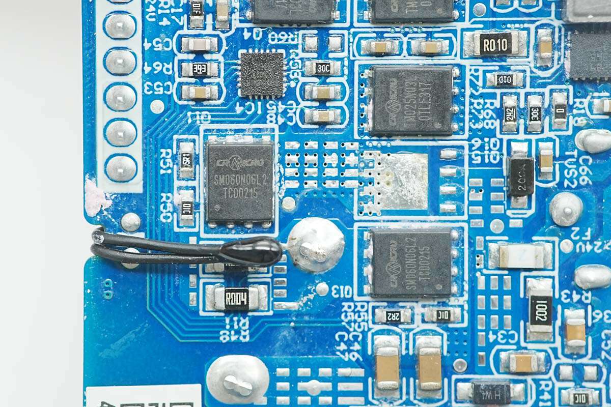
The synchronous buck MOSFETs are CRSM060N06L2 from CR MICRO. These are N-channel MOSFETs with a voltage rating of 63 V and an on-resistance of 5.3 mΩ. They are packaged in a DFN5×6 form factor.
Close-up of the second CR MICRO CRSM060N06L2 MOSFET.
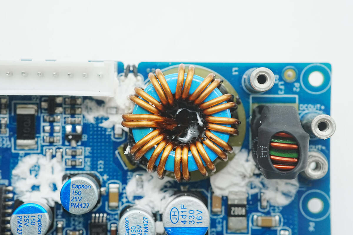
An insulating phenolic board is placed beneath the synchronous buck-boost inductor.
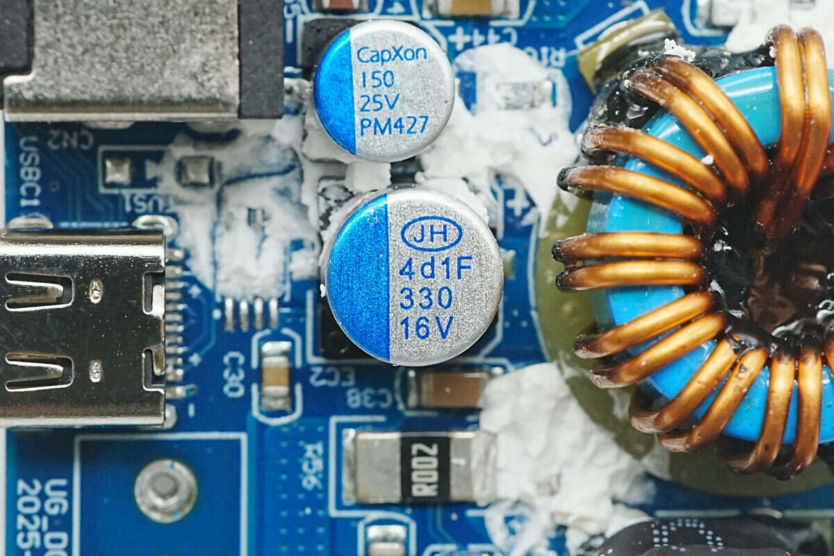
The output filter capacitor is from Jianghai, with a specification of 16V, 330μF.
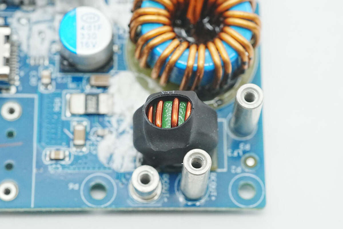
The filter inductor is insulated with heat shrink tubing.
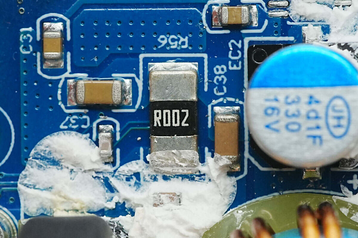
The 2mΩ sense resistor is used for current detection.
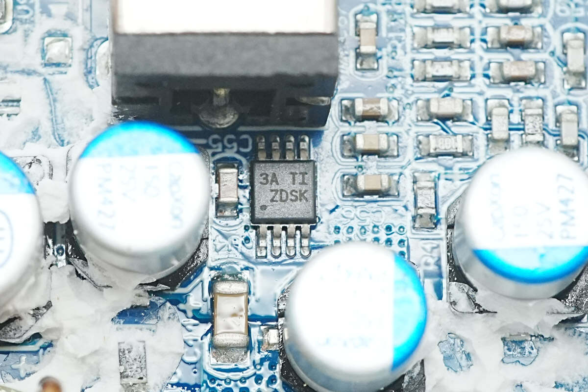
The ideal diode controller is the LM74610-Q1 from TI, marked with “ZDSK.” It is used for input pass-through control and comes in a VSSOP-8 package.
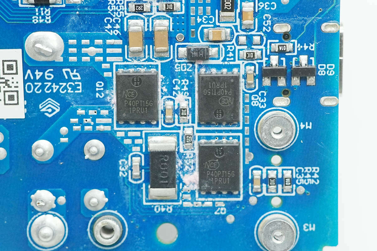
The switching MOSFETs are NCEP40PT15G PMOS devices from NCEPower, rated at -40 V with an on-resistance of 2.8 mΩ. They come in the DFN5×6-8L package. Three of these MOSFETs are used for power pass-through output and battery buck output switching.
Close-up of the SMD fuse at the input end.

The three filter capacitors are from CapXon, each rated at 25 V and 150 μF.
Close-up of the thermistor.
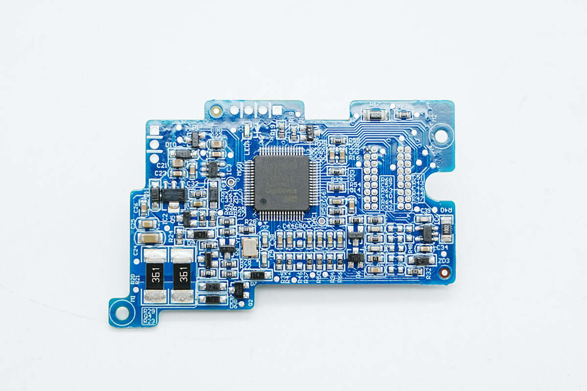
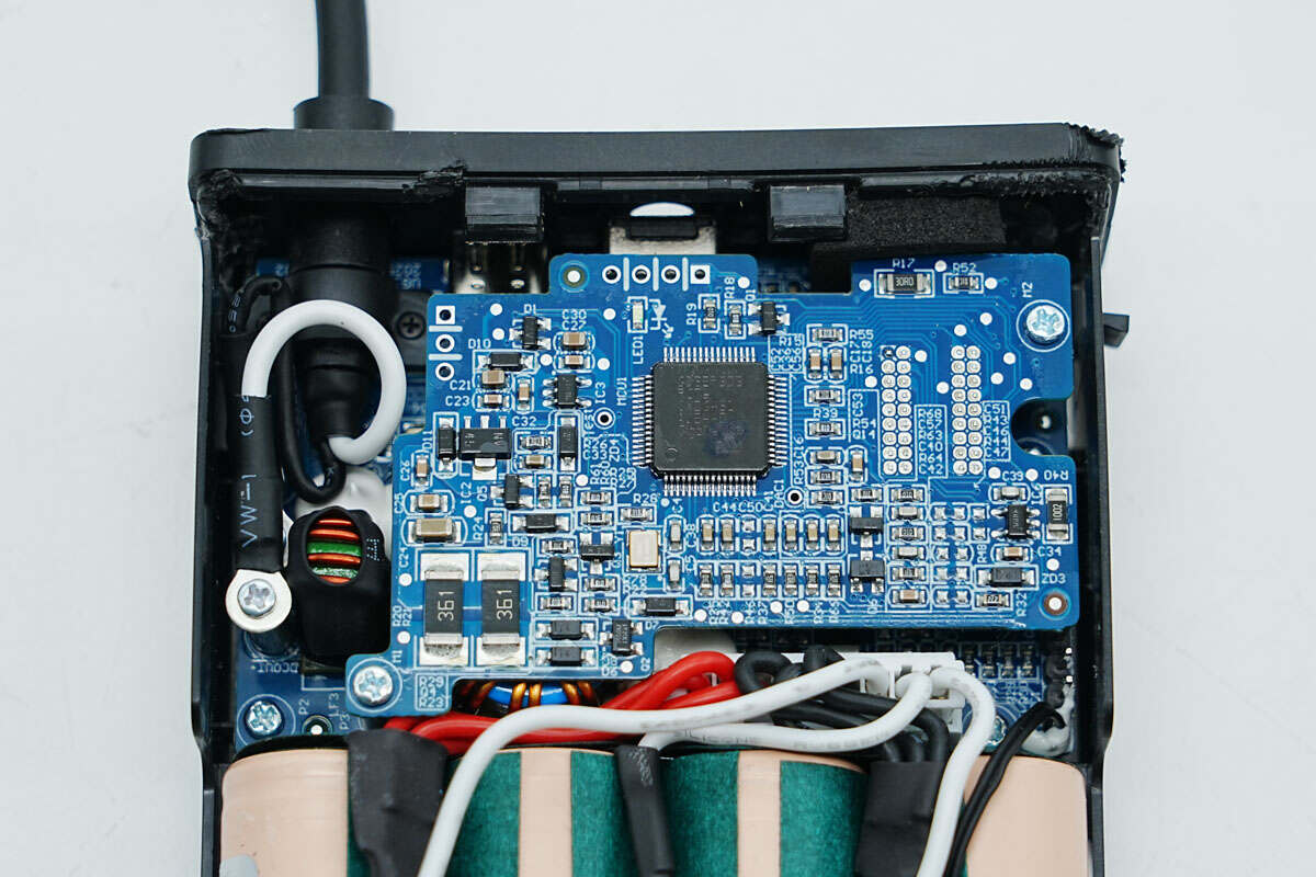
The front side of the upper PCB features an MCU for overall system control.
The other side includes connection headers and a buzzer.
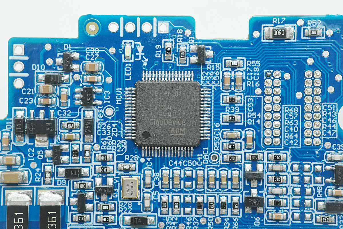
The MCU is a GD32F303RCT6 from GigaDevice, featuring a Cortex-M4 core running at up to 120 MHz. It has 256 KB of flash memory and 48 KB of SRAM, and supports PWM signal output.
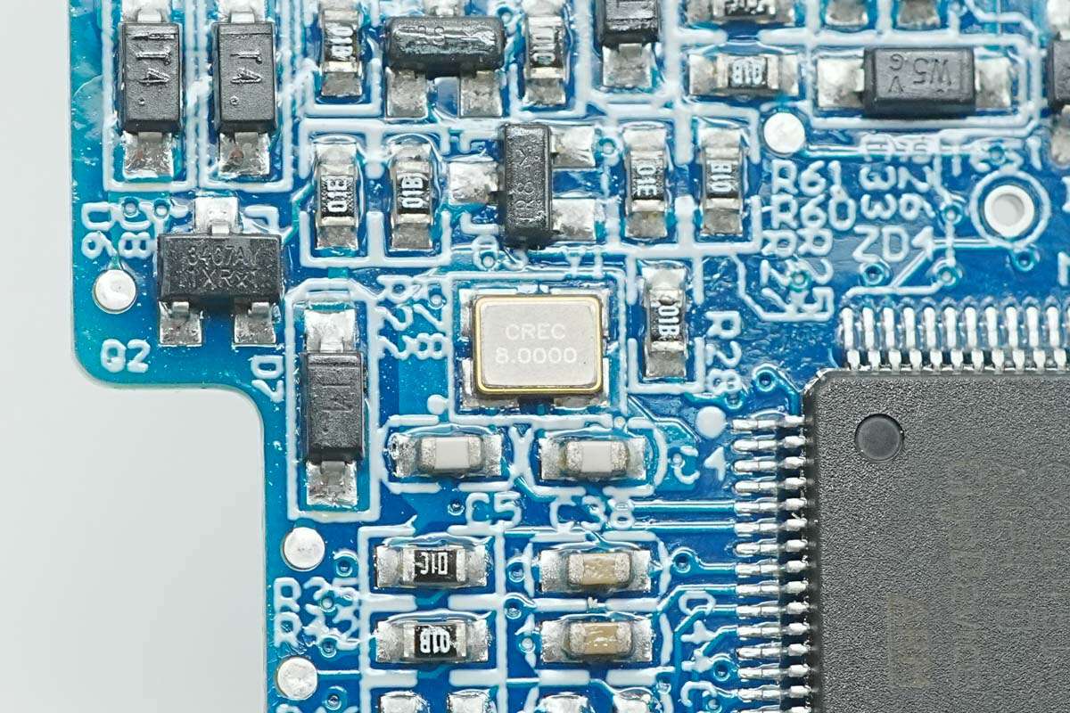
Close-up of the 8.0000MHz SMD crystal oscillator.
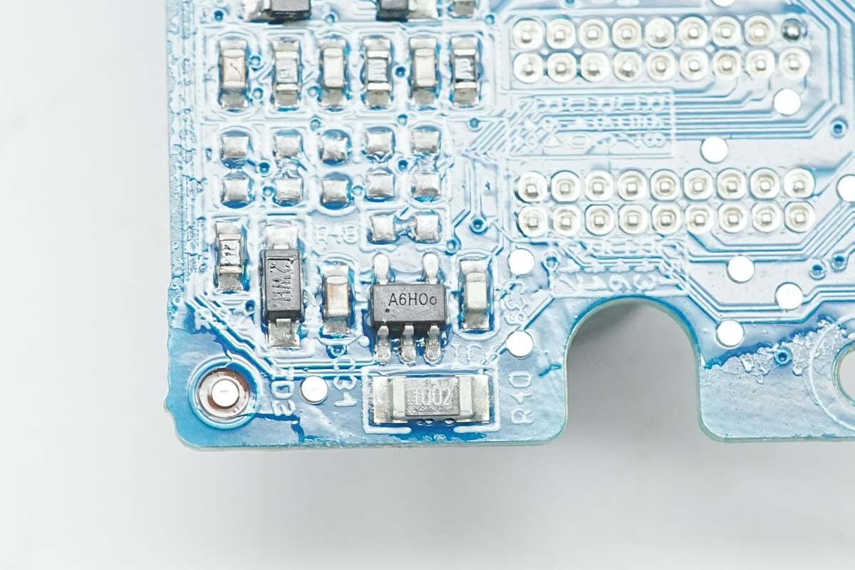
Close-up of the chip marked with "A6."
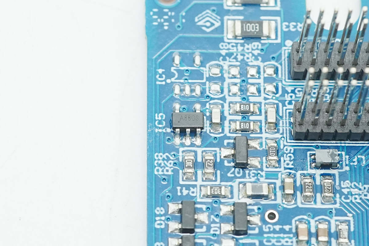
Close-up of the chip marked with "A8."
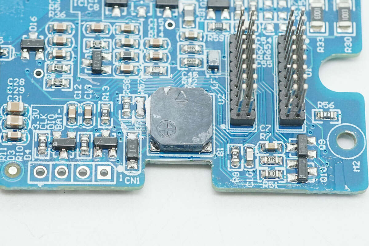
Close-up of the buzzer.

Well, those are all components of the UGREEN 120W DC UPS.
Summary of ChargerLAB
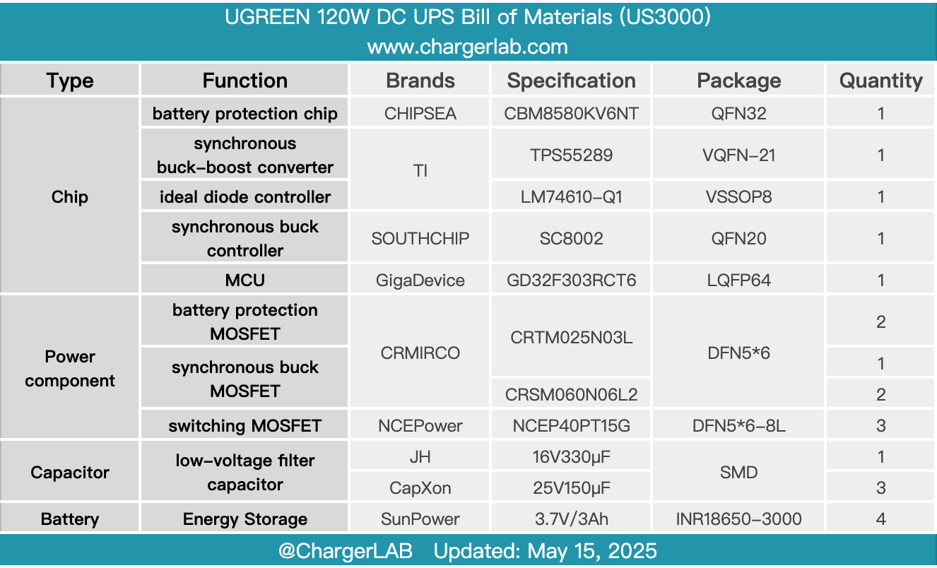
Here is the component list of the UGREEN 120W DC UPS for your convenience.
It features a unibody high-precision metal chassis that ensures a premium feel, enhanced drop resistance, and efficient heat dissipation. The built-in 12,000 mAh lithium-ion battery pack enables seamless 0-second switchover during power outages, ensuring uninterrupted operation and preventing data loss or file corruption.
It supports 12V 10A, 19V 7.9A, and 20V 7A input voltages, making it compatible with UGOS Pro-based systems, such as the DH2600, DX4600 series, DXP2800, DXP4800 series, and DXP480T Plus. It integrates nine protections, including power-off protection, short-circuit protection, and overheat protection. With technologies like overcharge, over-discharge, overvoltage, and surge protection, it ensures stable performance even in extreme conditions such as lightning storms and voltage fluctuations.
After taking it apart, we found that the battery pack consists of four SunPower INR18650-3000 cells connected in series, protected by the Chipsea CBM8580KV6NT. The power regulation solution uses the TI TPS55289 and the SouthChip SC8002, with MOSFETs supplied by CR MICRO and NCEPower. The MCU is a GigaDevice GD32F303RCT6. Fuses are present at both the input and battery ends, and it features well-implemented thermal management and insulation protection measures.
Related Articles:
1. Teardown of UGREEN Nexode Car Charger 90W with Retractable USB‑C Cable (EC603)
2. Teardown of UGREEN Thunderbolt 5 80Gbps M.2 NVMe SSD Enclosure (D705)
3. Teardown of OPPO 10000mAh 22.5W Energy Jelly Power Bank (PBSV00)