Introduction
In this teardown session, we dive into the muRata 1600W Server Power Supply (Model: D1U-H-1600-12-HC2C). Designed to accommodate both 100-127V and 200-240V AC inputs, this robust unit outputs a massive 12V rail at 131.6A, supplemented by a 3.3V/6A auxiliary standby rail.
Housed in an elongated rack-mount enclosure, the unit integrates heavy-duty mounting screws, an extraction handle, an AC socket, and a high-efficiency cooling fan, terminating with a specialized output connector at the rear. Under the hood, it employs a highly efficient PFC + ZVS full-bridge + synchronous rectification architecture. Join ChargerLAB as we peel back the layers to examine the premium engineering and component selection inside.
Be sure to check out our previous coverage of Murata's flagship 2000W Titanium Silicon Carbide (SiC) server power supply as well.
Product Appearance
Housed in a rugged galvanized steel chassis, the muRata 1600W server power supply sports a sleek, elongated, and flat profile. It integrates a high-efficiency cooling fan on the side, complemented by a clear identification label on the front face.
The power supply spec label:
Model: D1U-H-1600-12-HC2C
AC Input: 100-127V, 12A; 200-240V, 12-10A; 50-60Hz
DC Output: 12V: 131.6A @ 200-240V, 73.3A @ 100-127V; 3.3V, 6A
The chassis is secured via screws on the side.
The opposite side is also secured with screws.
The back of the chassis features an opening for debugging contacts.
The input end is equipped with a power socket and cooling fans, along with retaining screws, a carrying handle, and LED indicators.
This is the power socket at the input end.
The LED indicator light on the bottom right.
The output end is equipped with ventilation grilles and a connector.
The output connector.
The length of the PSU is about 300mm (11.811 inches).
The width of the PSU is about 120.8mm (4.756 inches).
The thickness of the PSU is about 40.8mm (1.606 inches).
The weight is about 2081g (73.41 oz).
Teardown
Now that we have explored the exterior of the muRata server power supply, it is time to peel back the layers and take a closer look at the engineering and components inside.
First, unscrew the retaining screws and disassemble the casing, which is insulated with Mylar sheet.
The PCBA is secured inside the casing with screws.
The AC input is connected via plug-in terminals, and the ground wire is secured to the enclosure with a screw.
Disconnect the AC input and cooling fan, unscrew the retaining screws, and remove the PCBA.
A Mylar insulation sheet is provided inside the casing.
The AC input line with a ferrite core for high-frequency interference suppression.
The cooling fan and LED indicators are connected via plug-in terminals.
The lower right section on the front of the PCBA module serves as the AC input end, equipped with a fuse, safety X2 caps, common-mode chokes, Y caps, a relay, and an NTC thermistor. Beneath the long heatsink on the upper right side are the PFC switching MOSFETs and PFC rectifier MOSFETs, with a PFC boost choke positioned in the middle.
Beneath the heatsink in the central position are the rectifier bridge and full-bridge switching MOSFETs. The transformer is located on the left side, with the standby power transformer situated below it, and high-voltage filter caps arranged at the bottom. The output connector is provided on the left side.
The back of the PCBA is equipped with a PFC controller, trigger, NAND gate, PWM controller, ZVS full-bridge controller, MCU, and synchronous rectifier MOSFETs.
A fuse is provided at the power input end.
The safety X2 cap is from Okaya, 1μF.
The common-mode inductor is wound with enameled wire.
Two blue Y-caps.
Two blue Y-caps are from muRata.
Another safety X2 cap shares the same model.
The common-mode inductor is wound with enameled wire.
The relay is from SONGCHUAN, model 302P-1AH-C, featuring a built-in normally open contact set with a contact rating of 17A 277VAC and a coil voltage of 12V.
The NTC thermistor is from TDK, model NTC10.
The varistor is from Panasonic, model ERZV07D431, with a varistor voltage of 430V, designed to absorb overvoltage surges.
The heatsink secures the full-bridge switching transistors and the rectifier bridge.
The bridge rectifier is from DIODES, model GBJ2506, rated at 25A 600V, in a GBJ package.
The PFC controller is from TI, model UC3854BDW, which is an enhanced high-power factor preregulator CCM PFC controller in an SOIC-16 package.
The voltage comparator is from onsemi, model LM311M, which is a single voltage comparator in an SOP-8 package.
Two triggers are from TI, model CD4013BM, which are dual-channel D-type flip-flops in an SOIC-14 package. The NAND gate model is CD4093BM, which is a quad 2-input NAND gate in an SOIC-14 package.
The PWM controller is from onsemi, model UC3843B, used for driving the PFC switching MOSFETs, in an SOIC-8 package. A total of three controllers are provided, which work together with the triggers and NAND gates to form a three-phase interleaved PFC circuit.
The operational amplifier is from ST, marked K405, model LM358ST, which is a low-power dual operational amplifier in a MiniSO-8 package.
There are 4 more operational amplifier chips of the same model.
The heatsink is equipped with three sets of PFC switching MOSFETs and PFC rectifier MOSFETs, which are secured by a pressure plate.
The PFC switching MOSFET is from Infineon, marked 20N60C3, model SPP20N60C3, NMOS, 650V and 190mΩ, in a TO-220 package.
The PFC switching MOSFET is from VISHAY, model VS-8ETX06-M3, which is an ultrafast recovery diode rated at 600V 8A, in a TO-220AC package.
The PFC boost choke is from muRata and is secured with potting compound for reinforcement.
The current transformer is used to detect the current of the switching MOSFETs and rectifier MOSFETs.
The PFC bypass diode.
The PFC output is filtered through electrolytic caps.
The high-voltage filter caps are from SAMXON, spec 270μF 450V, and the total capacitance of the four caps is 1080μF.
The ZVS full-bridge controller is from Renesas, model ISL6752, which is a zero-voltage switching full-bridge controller utilizing current-mode control with synchronous rectifier control outputs, in a 16-lead QSOP package.
The trigger is from TI, model CD4013BM.
Two drivers are from TI, model TPS2814, which are dual-channel high-speed 2A gate drivers with 2-input AND logic, supporting an operating temperature range of -40 to +125°C, in a TSSOP-8 package.
The voltage comparator is from TI, model LM339, which is a quad differential comparator in a TSSOP-14 package.
Another one shares the same model.
The driver is from TI, model TPS2814.
Another one shares the same model.
The optocoupler is from Renesas, model PS9117.
The two current transformers.
The transformer used for driving the switching MOSFETs.
Another transformer.
The switching MOSFET is from VISHAY, model Si7846DP, NMOS, 150V and 50mΩ, packaged in a PowerPAK SO-8 package.
The heatsink also has two switching MOSFETs of same model.
The full-bridge switching MOSFETs are from ST, model STP20NM50, NMOS, 500V and 250mΩ, in a TO-220 package.
Other two switching MOSFETs share the same model.
An aluminum plate is adhered to the core of the planar transformer.
A heatsink is adhered to the opposite side.
A filtering choke is positioned on the side of the transformer.
Another one is provided on the other side.
The isolation transformer PCB.
The filtering cap is from SAMXON, 1000μF 16V.
A total of 5 filtering caps of same model are provided.
Here is the PCB solder jumper.
The output control MOSFETs are from Infineon, model BSC025N03LS, NMOS, 30V and 2.5mΩ, in a TDSON-8 package.
Two output control MOSFETs of the same model are also located on the corresponding position on the back.
The other set of output control MOSFETs is of the same model.
Two output control MOSFETs of the same model are also located on the corresponding position on the back.
The MCU is from Infineon, model CY8C24423A, with an integrated 24MHz M8C CPU, 4KB of flash memory and 256B of SRAM, and is packaged in a 28 SSOP package.
The memory is from MICROCHIP, marked 4A24I, model 24AA024, with a capacity of 256B, supporting an operating voltage range of 1.7V to 5.5V, housed in an 8-lead MSOP package.
The operational amplifier is from TI, model TLV274C, which is a quad-channel rail-to-rail output operational amplifier, housed in a TSSOP-14 package.
Another one shares the same model.
The voltage comparator is from TI, model LM339A, which is a commercial-grade precision quad differential comparator, housed in a TSSOP-14 package.
The voltage comparator is from TI, model LM339.
The voltage comparator is from TI, model LM339.
The drivers are from TI, model TPS2814, which are utilized for synchronous rectifier driver applications.
The operational amplifier is from ST, model LM358ST.
The operational amplifier is from ST, model LM358ST.
The operational amplifier is from ST, model LM358ST.
The diode is from onsemi, marked U5D, model MURA220T3G, which is an ultrafast recovery diode rated at 200V, 2A, housed in an SMA package.
The switching MOSFET is from Infineon, model IRF7205, PMOS, -30V and 70mΩ, and an SO-8 package.
The diode is from onsemi, model MURA220T3G.
The optocoupler is from VISHAY, model SFH690BT, utilized for isolated feedback control.
The three optocouplers are of the same model.
The standby controller IC is from onsemi, model UC3842B, which is a high-performance current-mode controller, housed in an SOIC-8 package.
The standby power switching MOSFET is from ST, model STD3NK80Z, NMOS, 800V and 4.5Ω, housed in a DPAK package.
The switching MOSFET is from Infineon, model IRF7205.
The filtering cap is from NCC, 25V 560μF.
Another one shares the same model.
Insulating tape is adhered to the core of the planar transformer for electrical isolation.
The blue Y-cap.
The filtering cap is from SAMXON, 1000μF 25V.
Another filtering cap, 220μF 25V.
The Schottky diode is from ST, model STPS30L45CT, rated at 30A, 45V, housed in a TO-220AB package.
The other Schottky diode, model STPS40L15CT, is rated at 40A, 15V, and housed in a TO-220AB package.
This is the filtering choke.
An NTC PCB used for temperature detection.
The cooling fan is from Delta, model FFB0412SHN, spec 12V 0.6A.
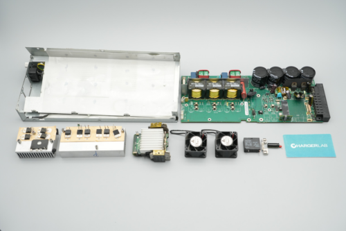
Well, those are all components of the muRata 1600W Server Power Supply (D1U-H-1600-12-HC2C).
Summary of ChargerLAB
muRata’s high-performance server power supply (Model: D1U-H-1600-12-HC2C) supports a wide voltage range of 100–127V and 200–240V AC input. It delivers a steady 12V rated output at 131.6A, along with a dedicated 3.3V/6A standby power output. The unit features an integrated cooling fan and AC socket on the input side, with a robust connector on the output side for seamless integration.
A teardown by ChargerLAB indicates that this unit employs an advanced PFC + ZVS full-bridge + synchronous rectification architecture. Core components include a TI UC3854BDW PFC controller and a Renesas ISL6752 ZVS full-bridge controller. The PFC stage uses an Infineon SPP20N60C3 MOSFET and a VISHAY VS-8ETX06-M3 rectifier MOSFET.
Further powering the design are ST STP20NM50 full-bridge switches and Infineon BSC025N03LS output control MOSFETs. Built with top-tier reliability in mind, the internal circuitry relies on premium electrolytic caps from SAMXON and NCC, guaranteeing premium build quality throughout.
Related Articles:
1. Teardown of the muRata’s 2000W Titanium-Rated SiC Server PSU
2. MURATA US21700-VX40 Tabless Battery, 50% Charge in Just 10 Minutes!
3. PowerPi MP305B DC Power Supply Set to Launch on Amazon US — Efficient Power for All Scenarios