Introduction
StarCharge has released a new 7kW smart AC charger with a front LED light bar and display screen for clear, real-time charging status updates. It supports 220V power, works with most EVs, and includes lifetime free 4G connectivity with app-based remote control.
It features IP67 protection against water and dust, making it suitable for extreme environments. The upgraded thermal management system provides triple temperature protection for key components. Solder-filled terminals reduce heat, and the charging plug uses ultrasonic welding for enhanced safety and durability. Next, let’s take it apart to see its internal components and structure.
Product Appearance
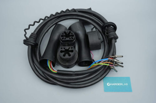
The StarCharge Smart Charger is packaged in a corrugated cardboard box.
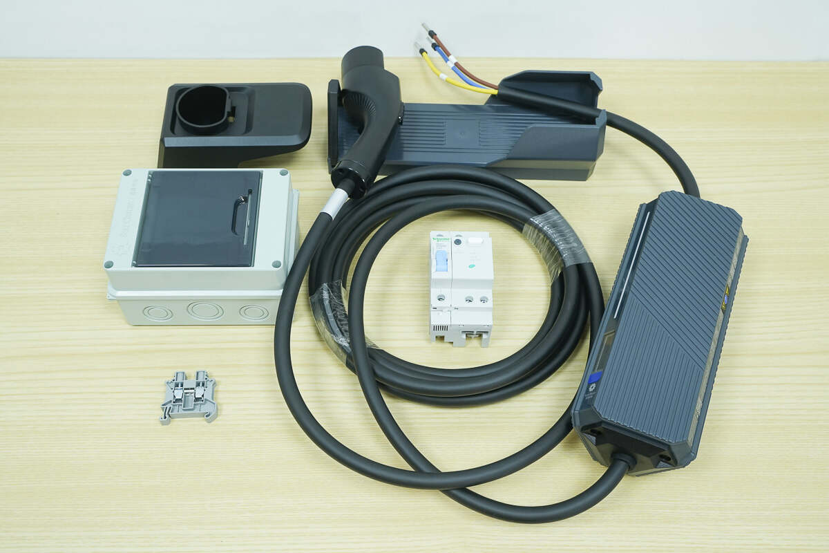
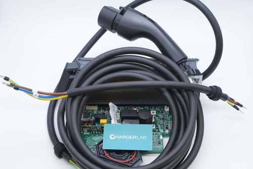
The packaging includes the charger unit, mounting bracket, Schneider residual current circuit breaker (RCCB), and a charging connector socket.
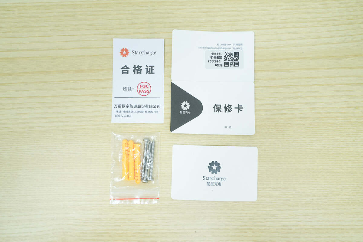
Close-up of the certificate of conformity, warranty card, and installation screws.
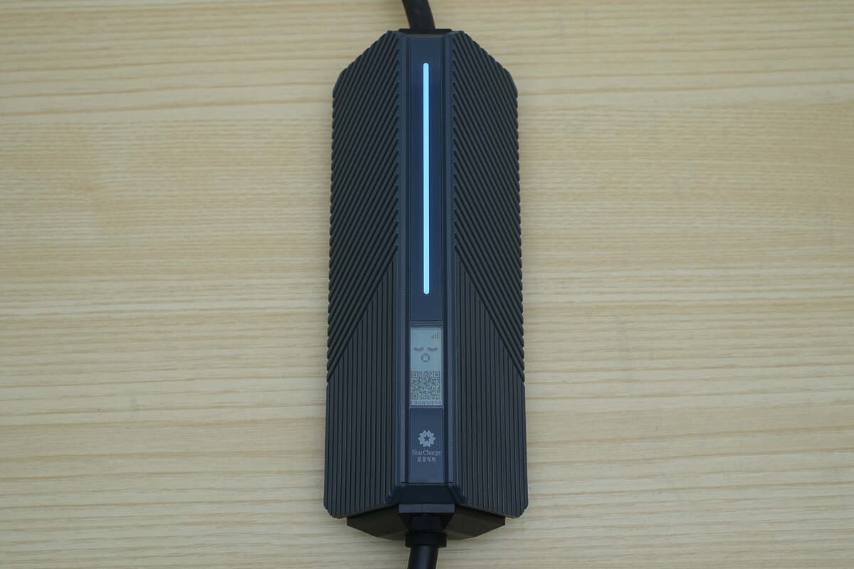
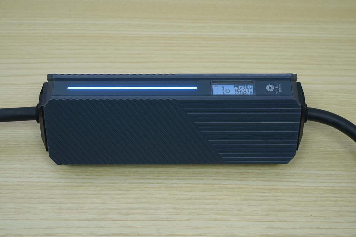
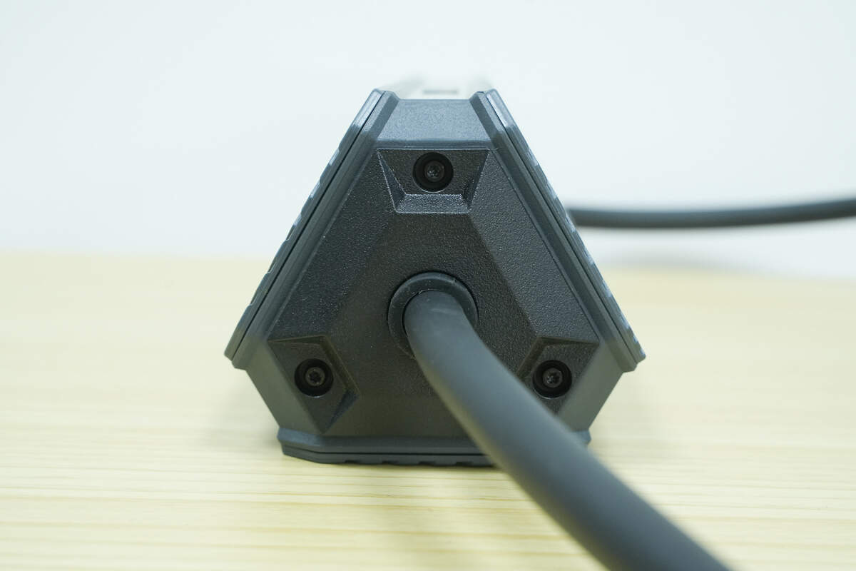
The charger features a triangular prism-shaped body with an LED light strip and a screen on the front.
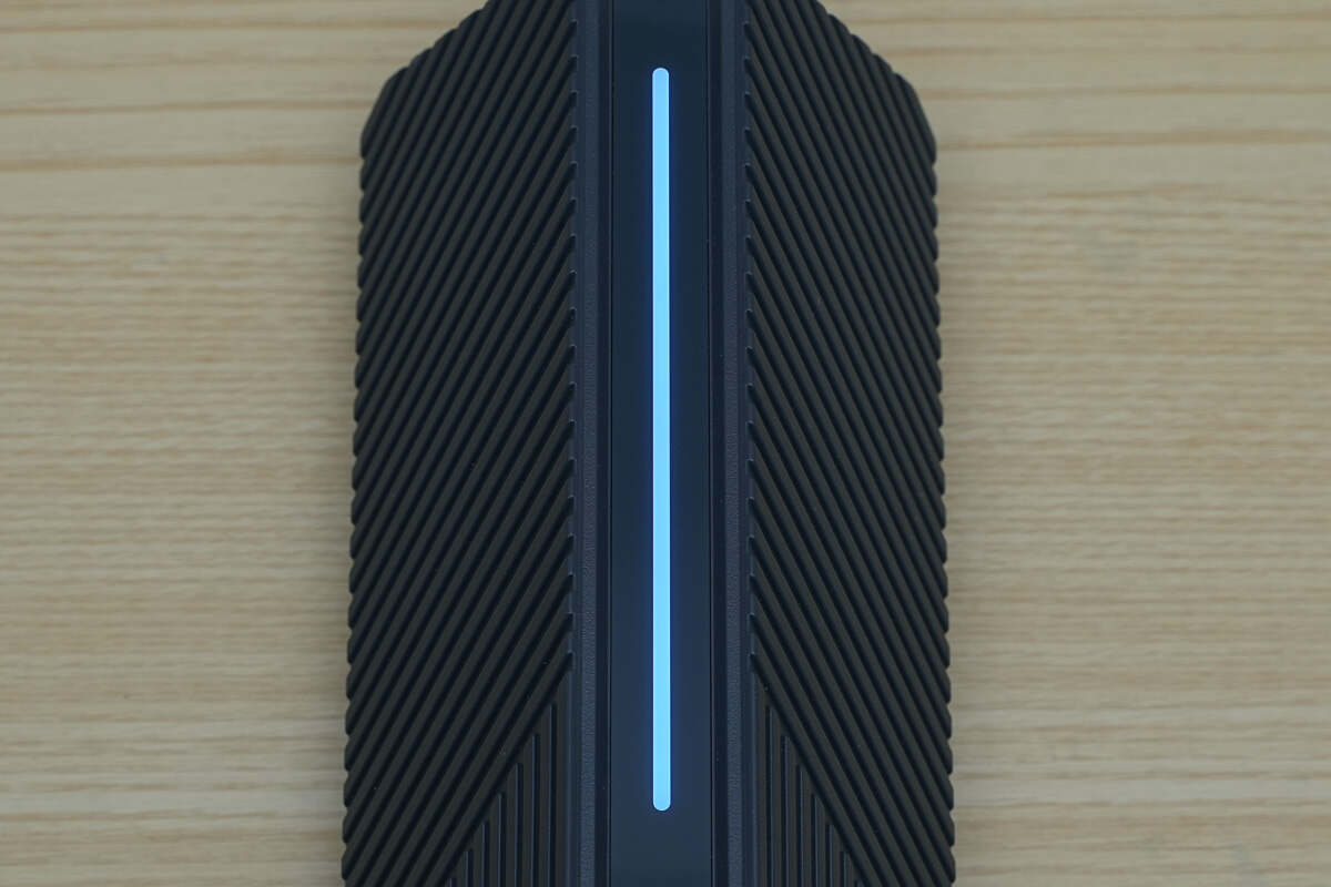
The LED light strip indicates connection and charging status.
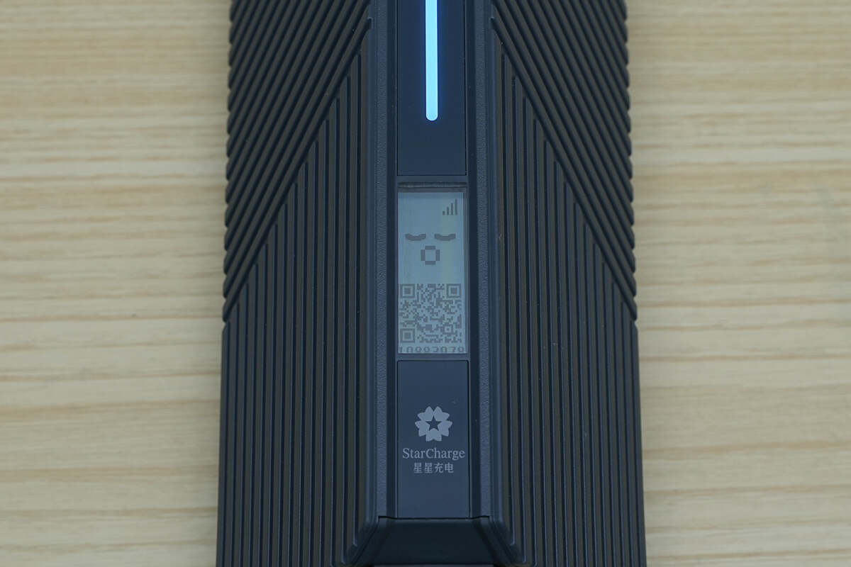
The screen currently shows a "waiting to charge" status and supports various charging status displays. The StarCharge logo is printed below the screen.
The side features patterned decorative elements.
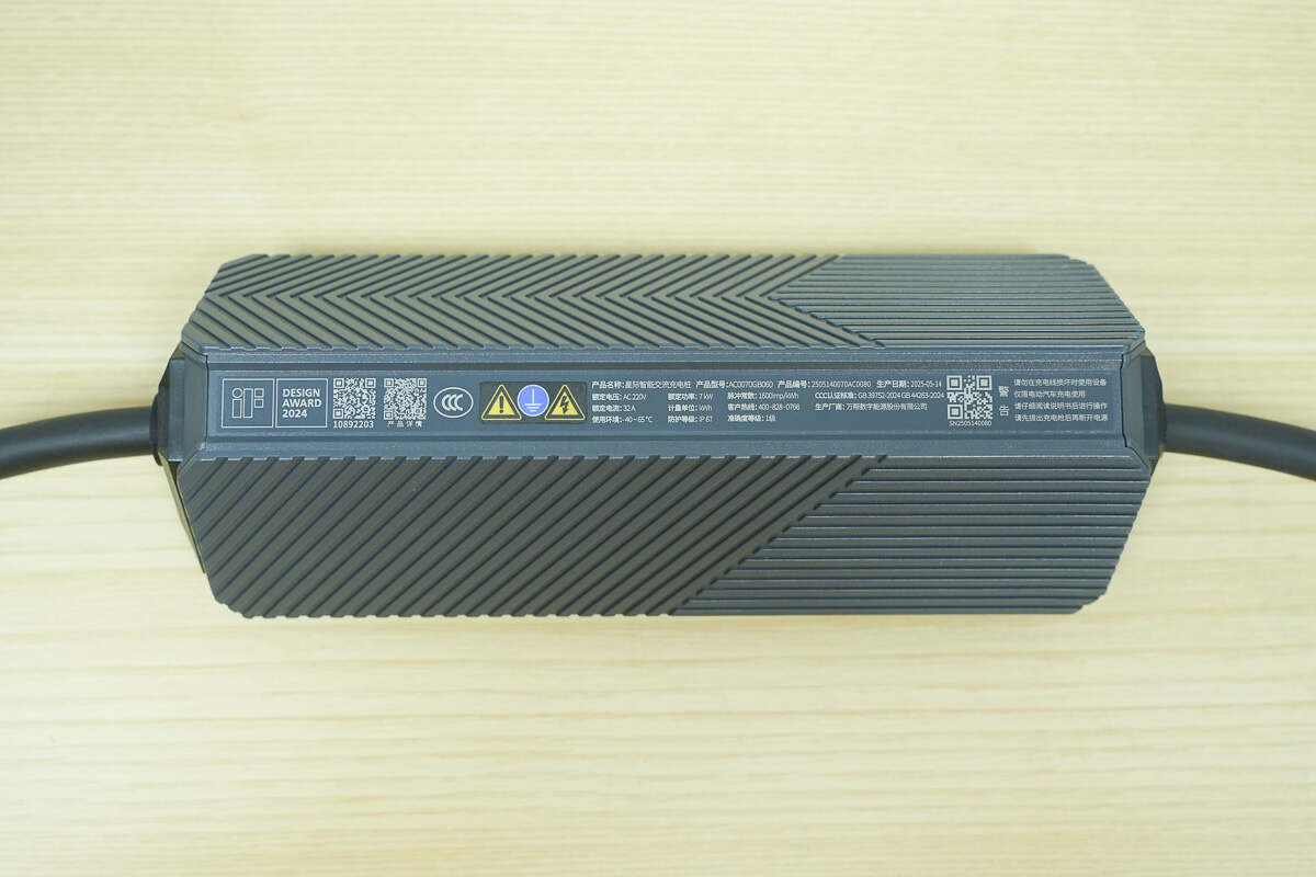
This is the product nameplate.
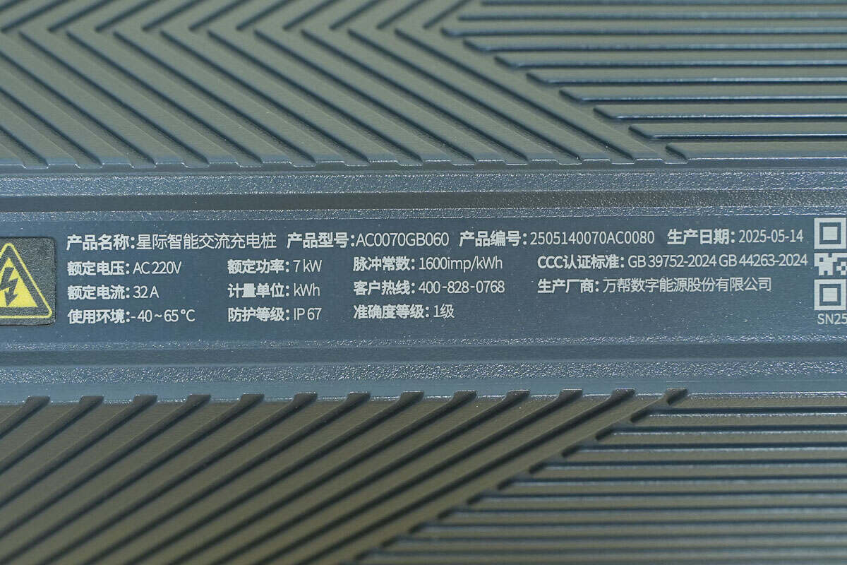
Model: AC0070GB060
Rated Voltage: AC 220V
Rated Current: 32A
Rated Power: 7kW
Measurement Unit: kWh
Pulse Constant: 1600 imp/kWh
Operating Environment: -40 to 65°C
Protection Rating: IP67
Accuracy Class: Class 1
CCC Certification Standards: GB 39752-2024, GB 44263-2024
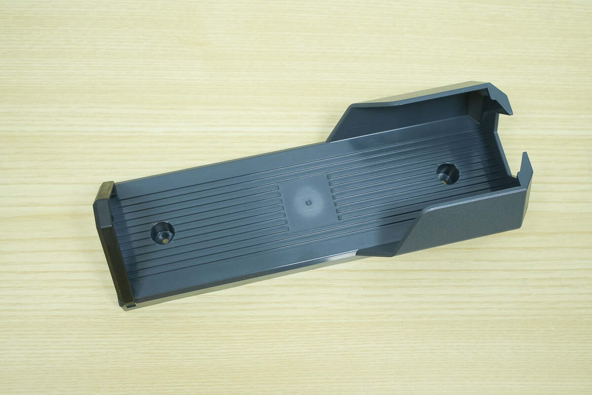
The side cover is secured with mounting screws.
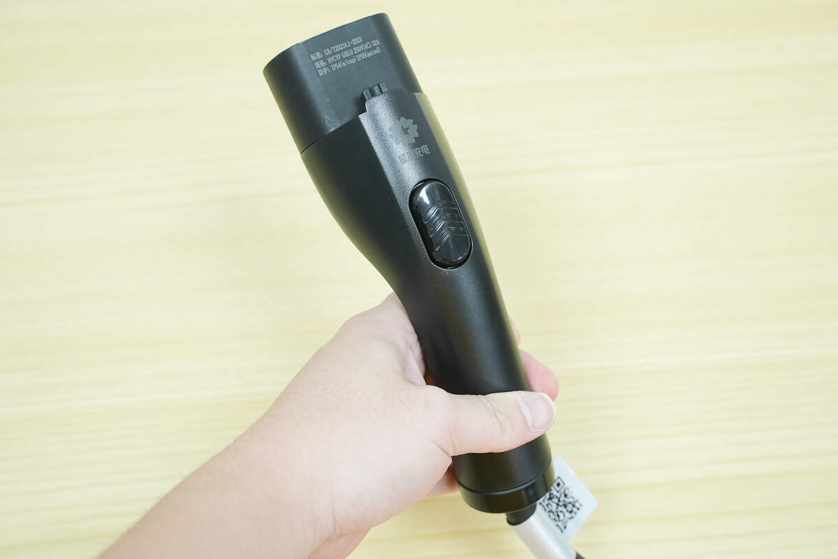
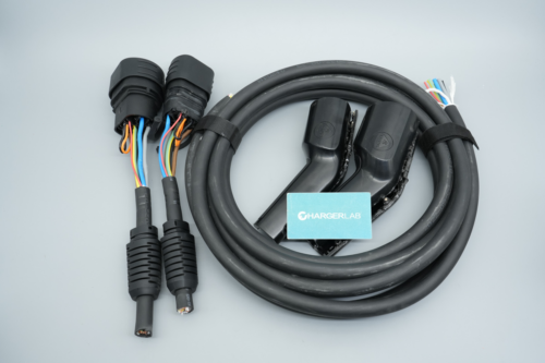
The front of the charging connector features the StarCharge logo and a release button.
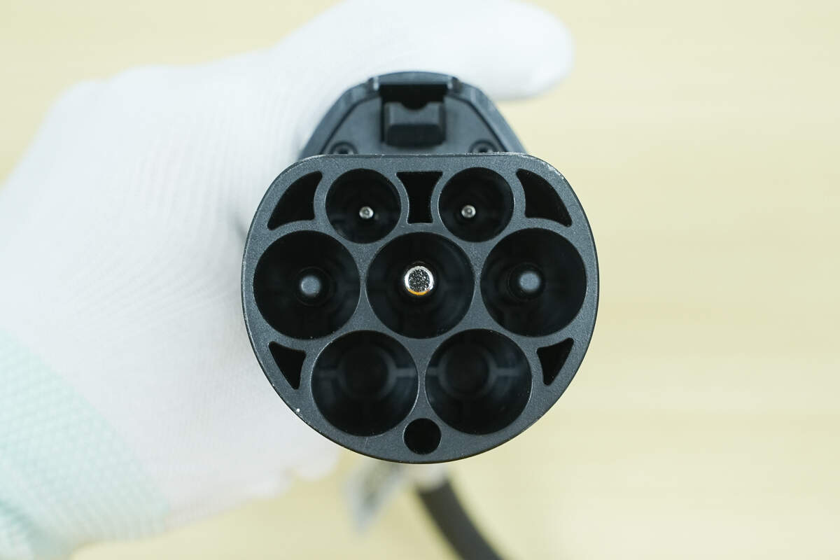
The connector is a 7-pin AC charging plug, compatible with major new energy vehicle brands.
Close-up of the mounting bracket.
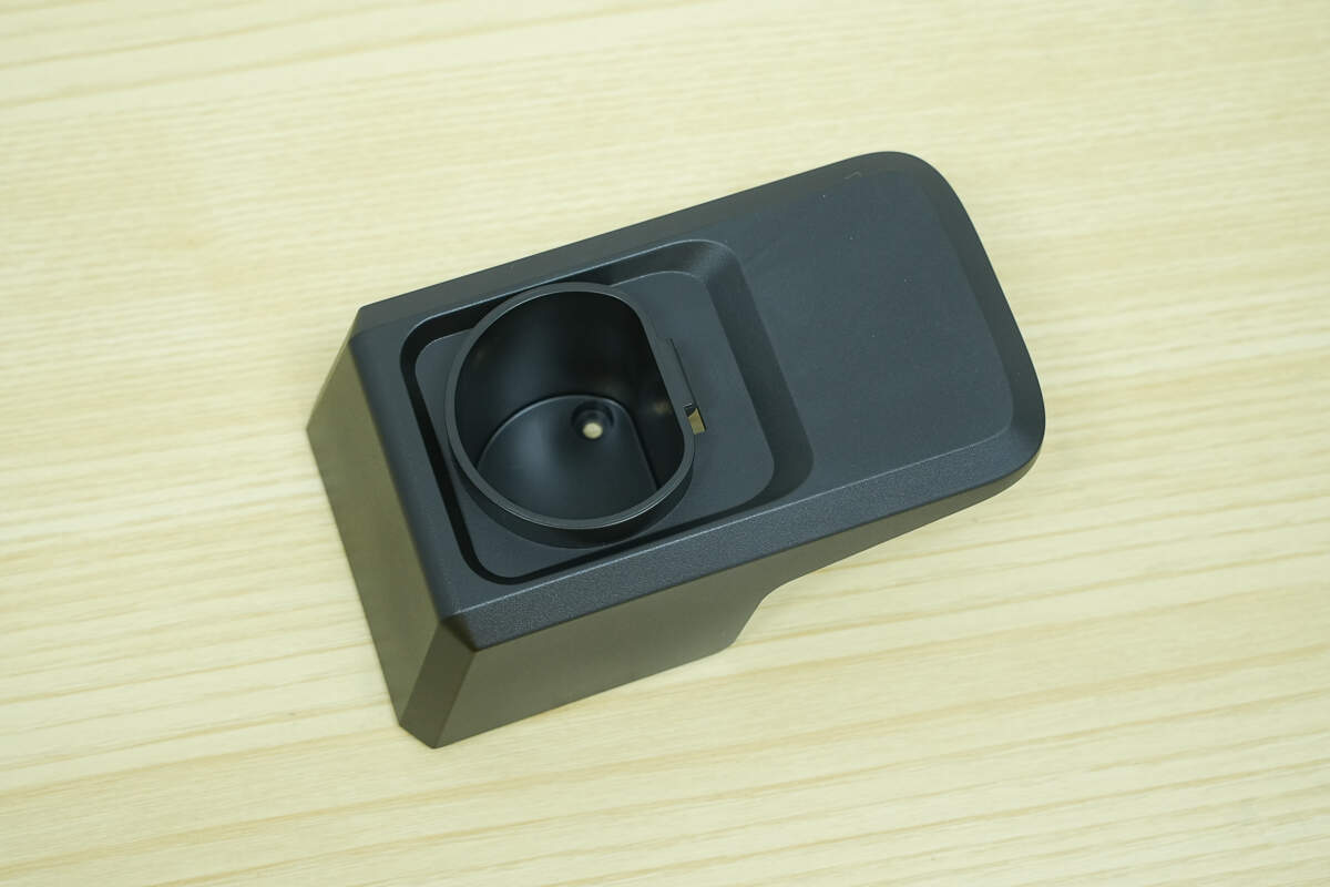
Close-up of the charging connector socket.
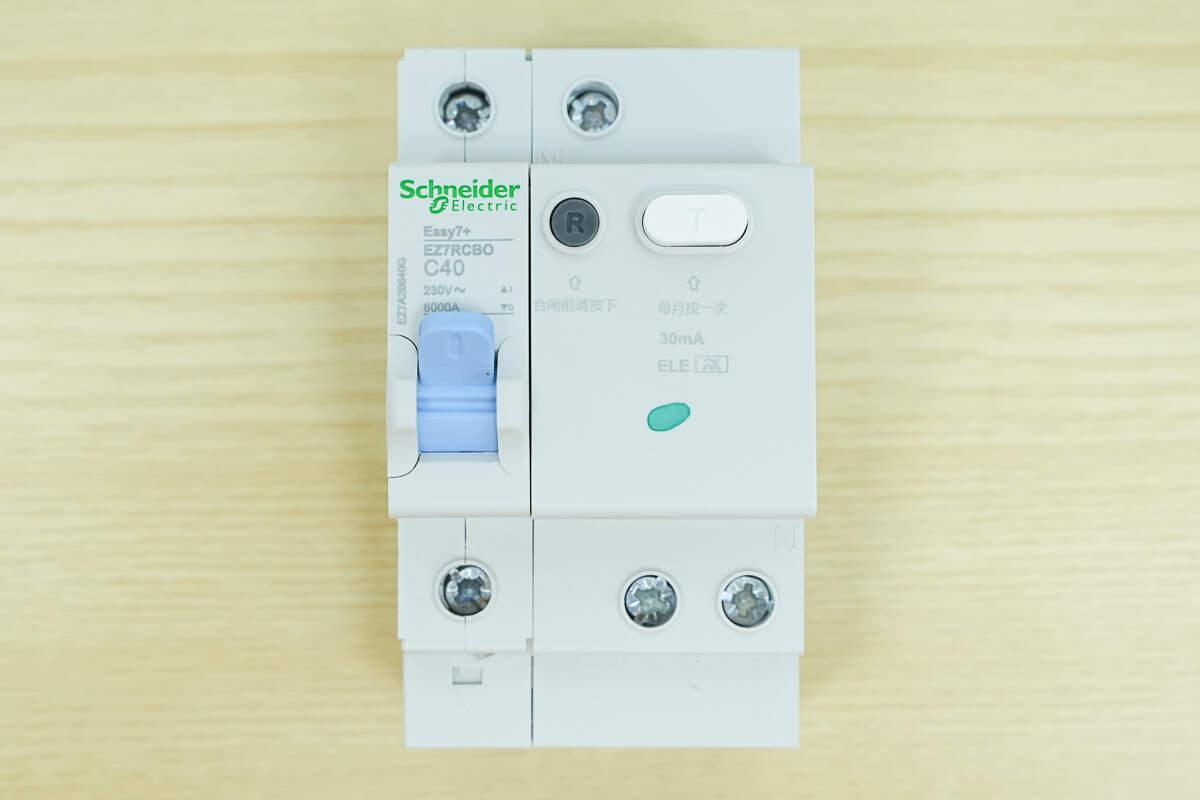
Includes a Schneider residual current circuit breaker (RCCB) from the Easy7+ series.
Teardown
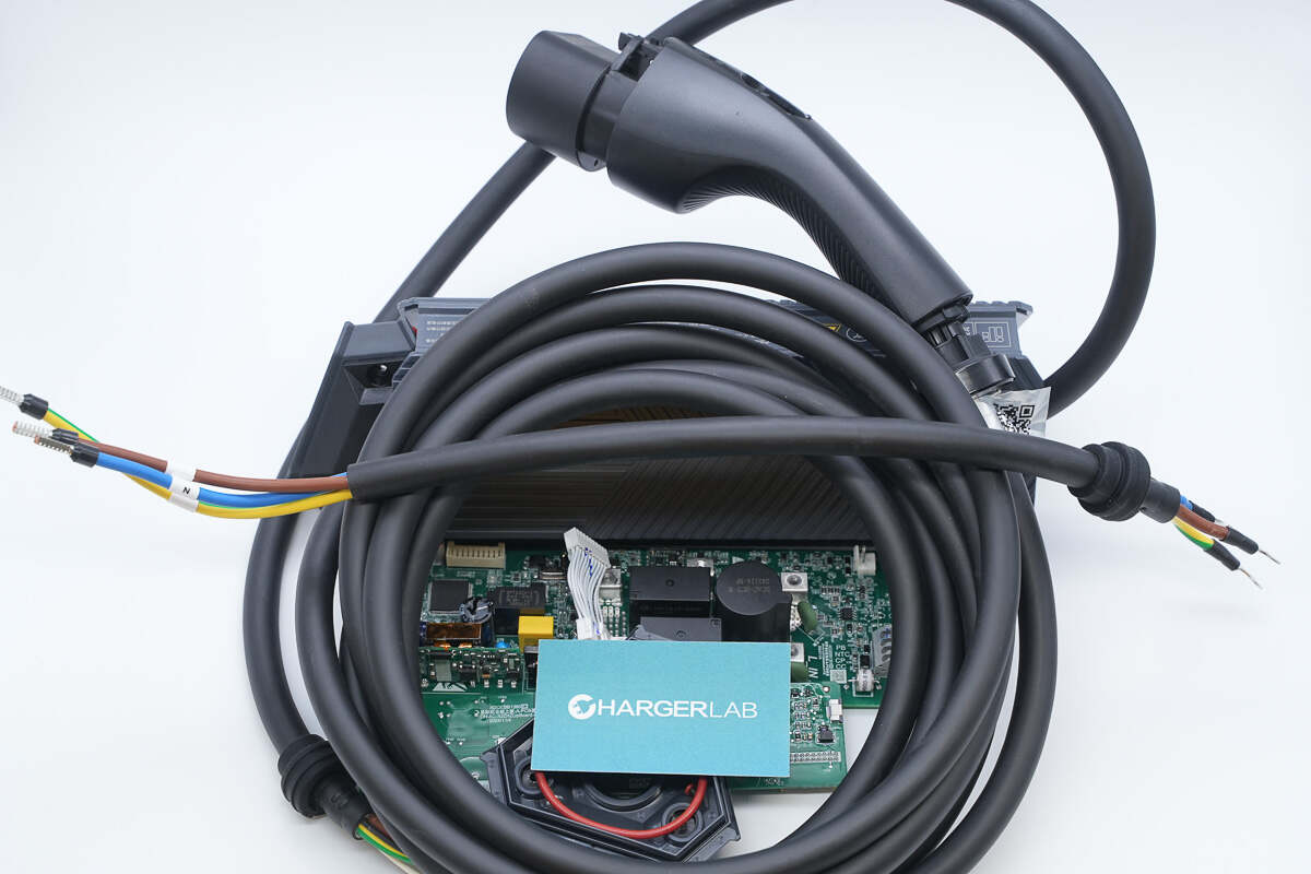
Next, let's take it apart to see its internal components and structure.
Unscrew the screws to remove the side cover of the charger.
Each screw is equipped with an orange sealing ring.
There is also an orange sealing ring between the cover and the housing.
The charger housing and mounting screws are each equipped with sealing rings, effectively sealing the charger body and providing a high level of protection.
It has strong waterproof capability, having been tested for 30 minutes at a depth of 1 meter without any faults.

It also has excellent dust resistance. Tested in a dust concentration of 2 kg/m³ for 8 hours in a sealed environment, no dust entered the charger, and it continued to operate normally.
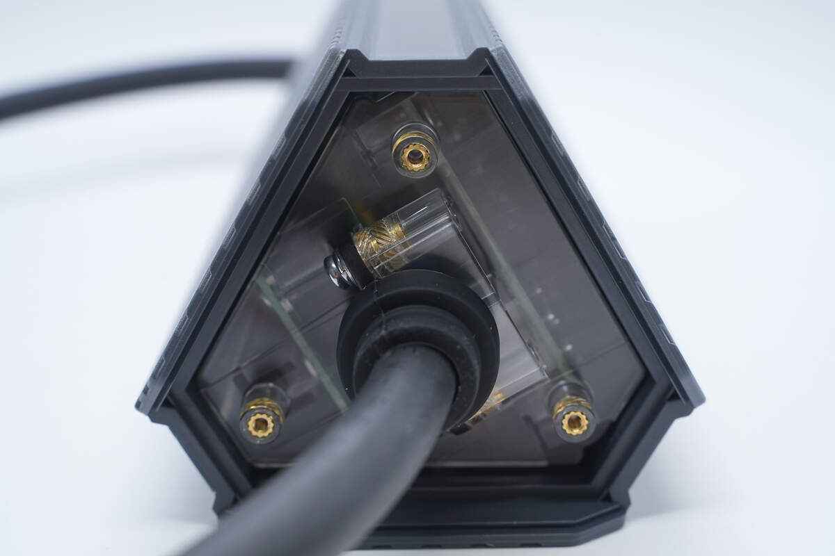
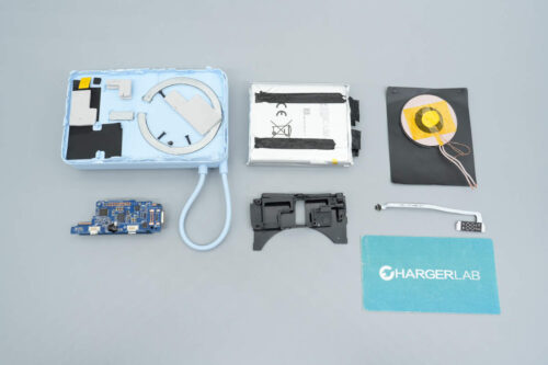
The charger housing features a double-layer structure, with a transparent inner shell.
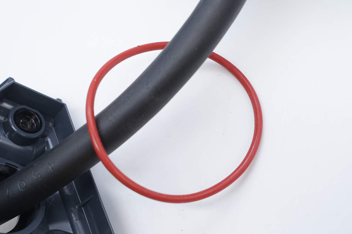
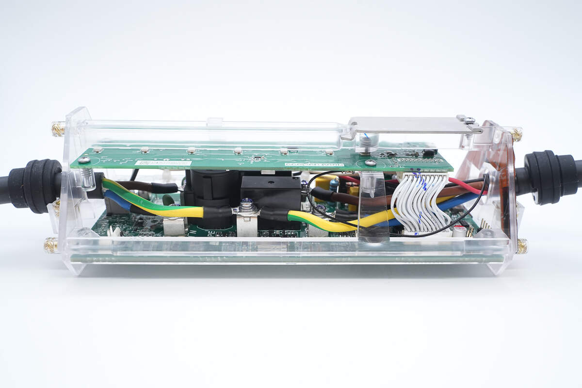
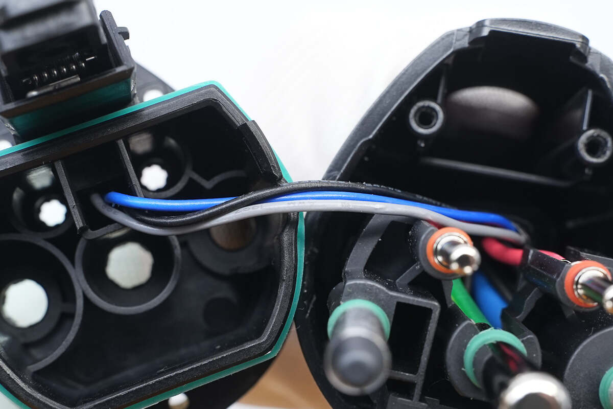
The cables are secured using a screw clamp.
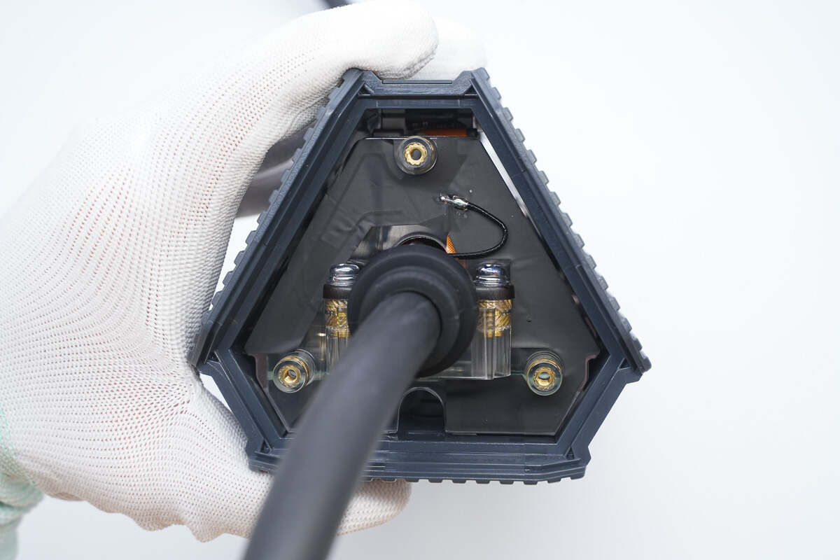
The other side cover has a wireless communication antenna attached.
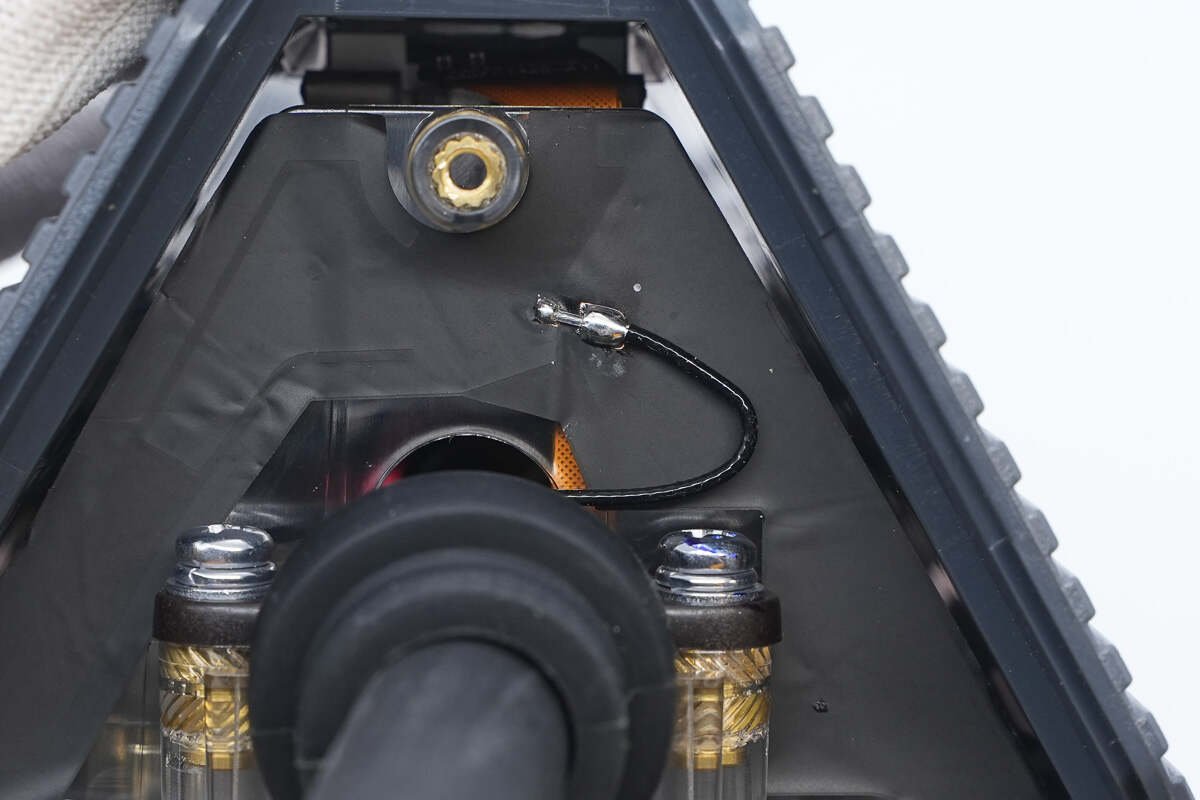
The antenna is connected via a coaxial feedline using soldering.
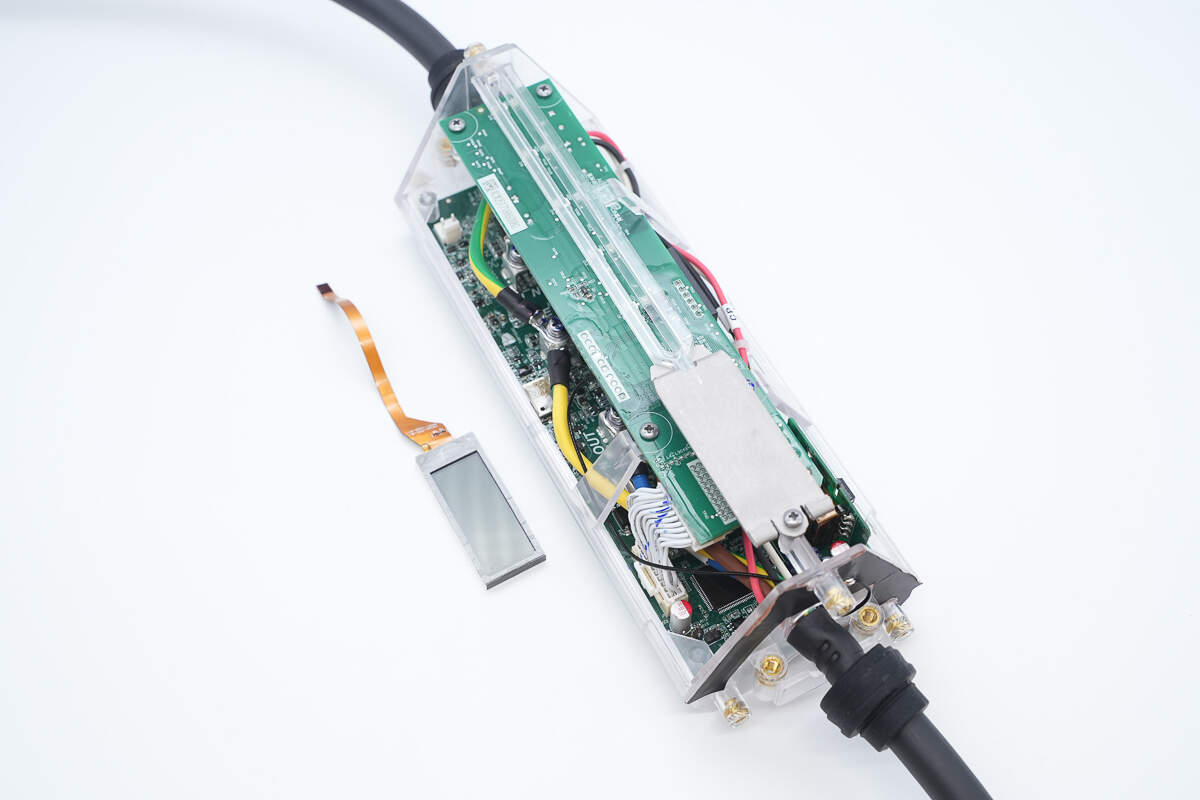
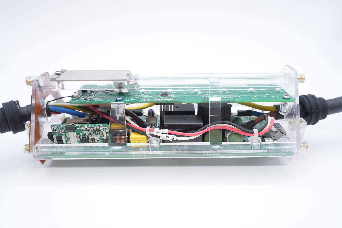
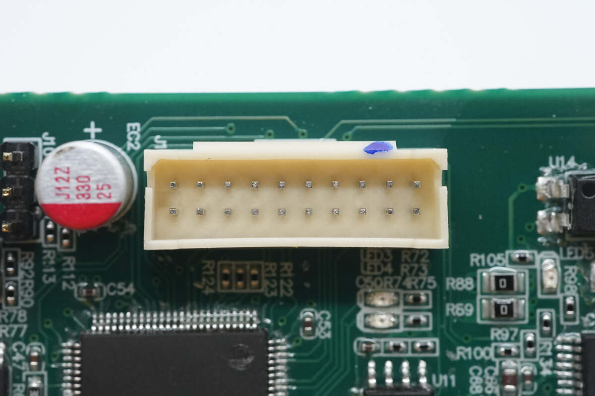
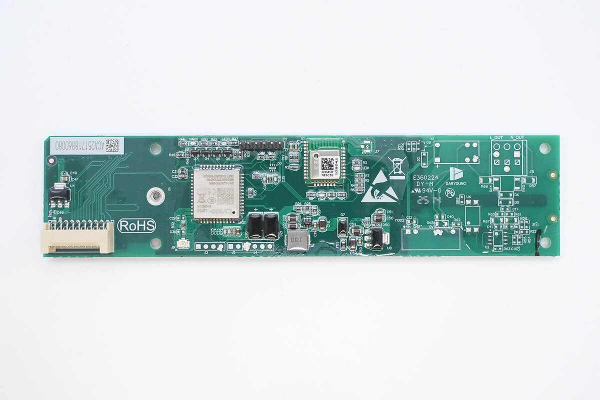
The screen is connected to the PCBA module via a ribbon cable.
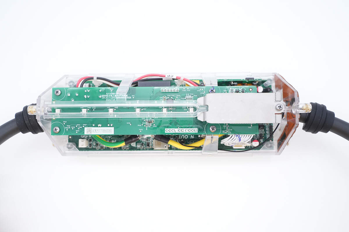
The PCBA module is secured inside the transparent housing with screws.
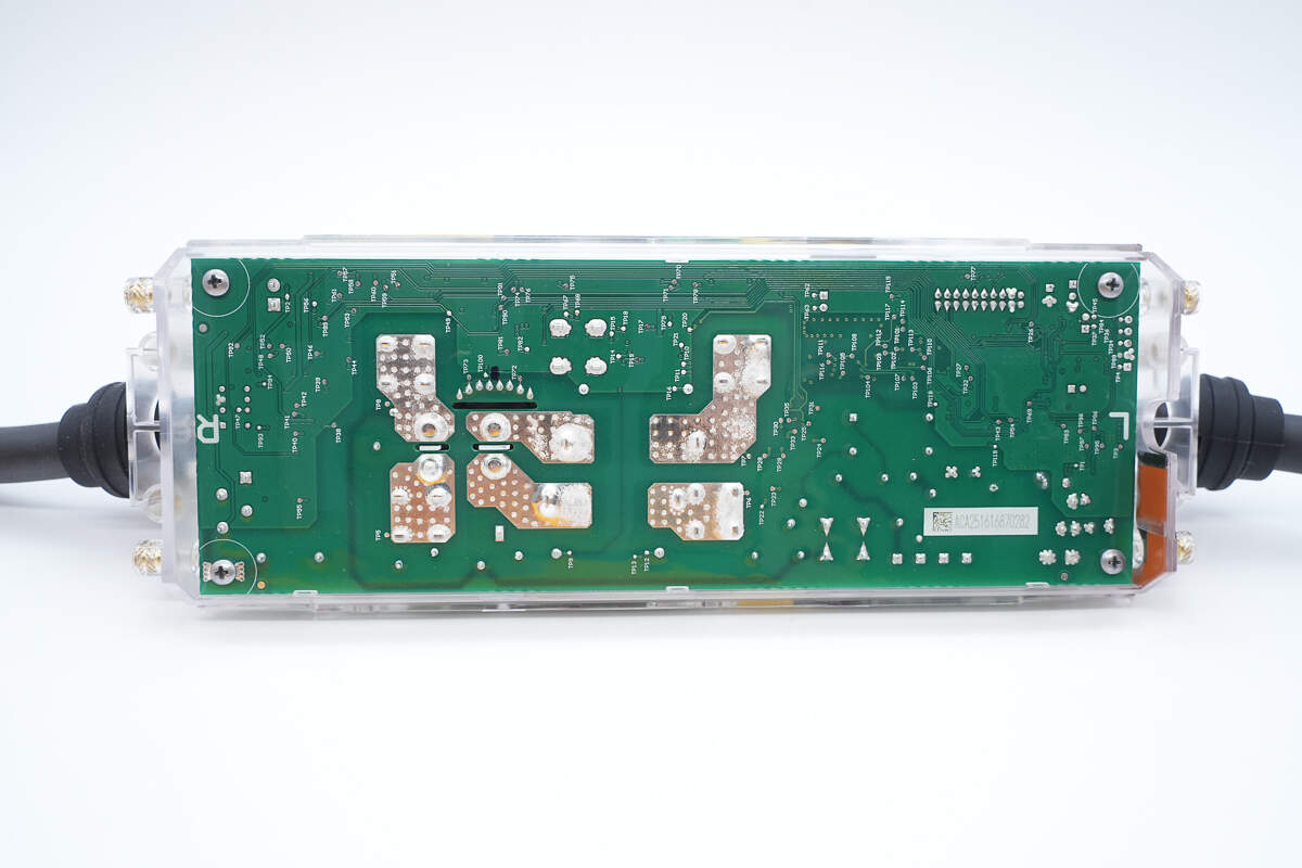
The bottom PCBA module is also secured with screws.
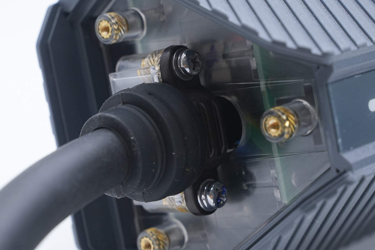
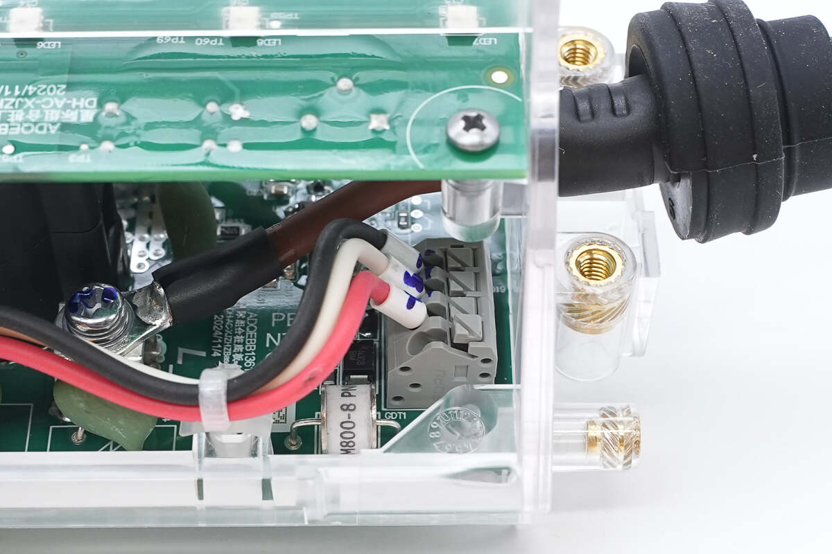
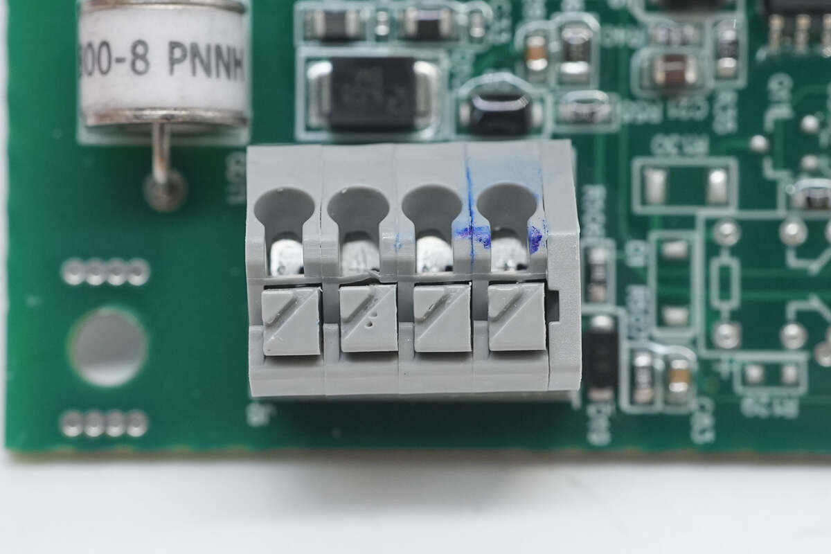
The wires are secured using screw terminals.
The two PCBA modules are connected via a ribbon cable.
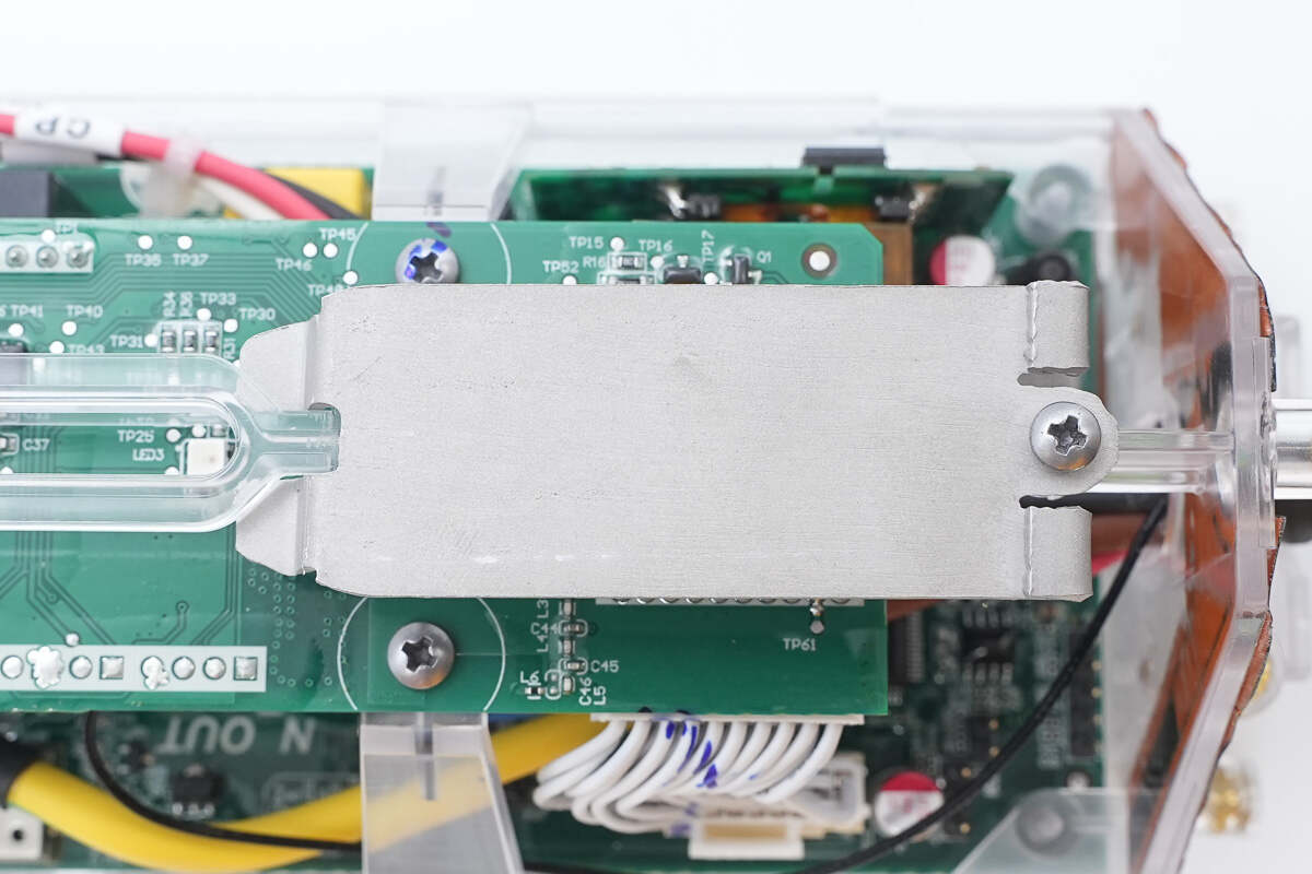
The LCD screen is secured with a metal bracket.
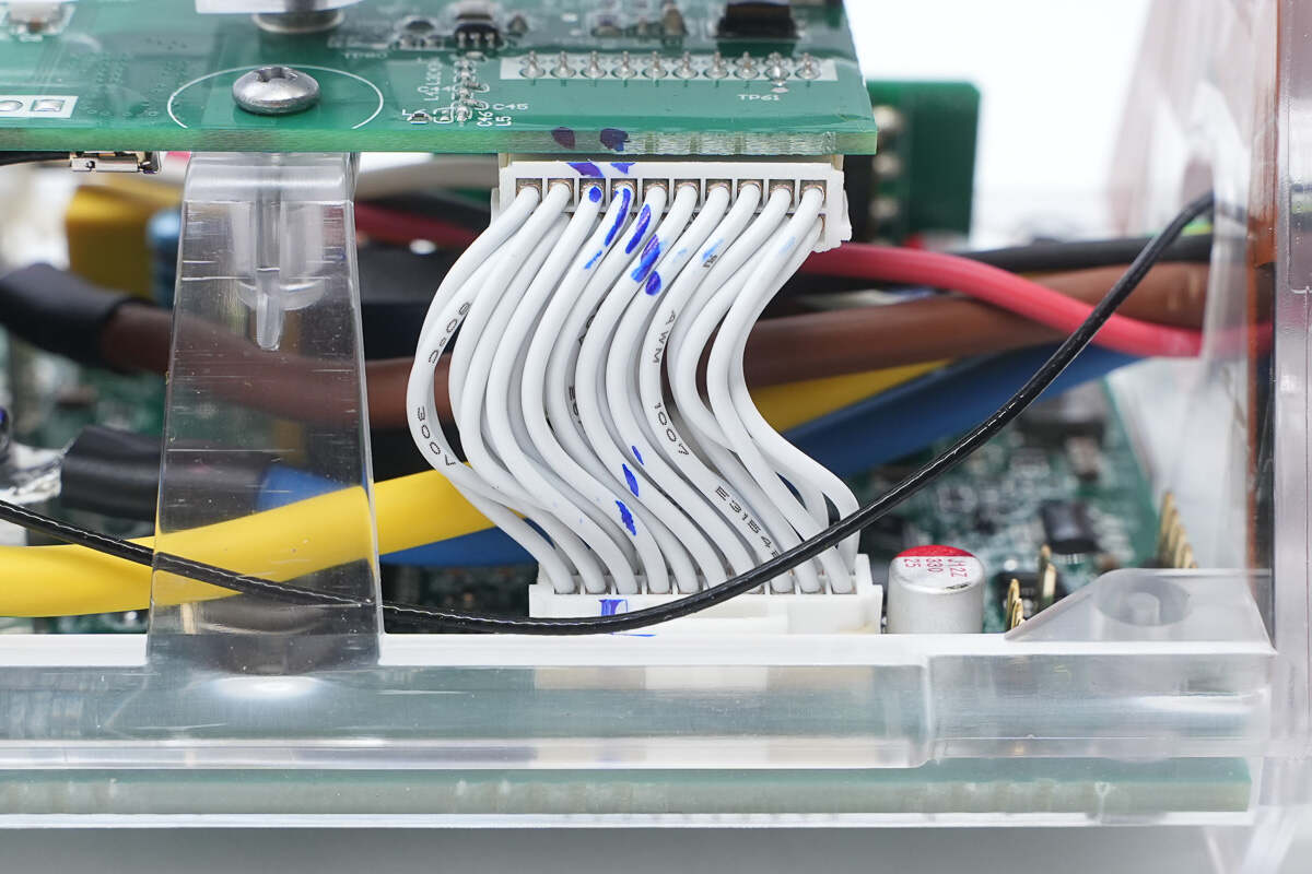
Close-up of the ribbon cable connecting the PCBA modules.
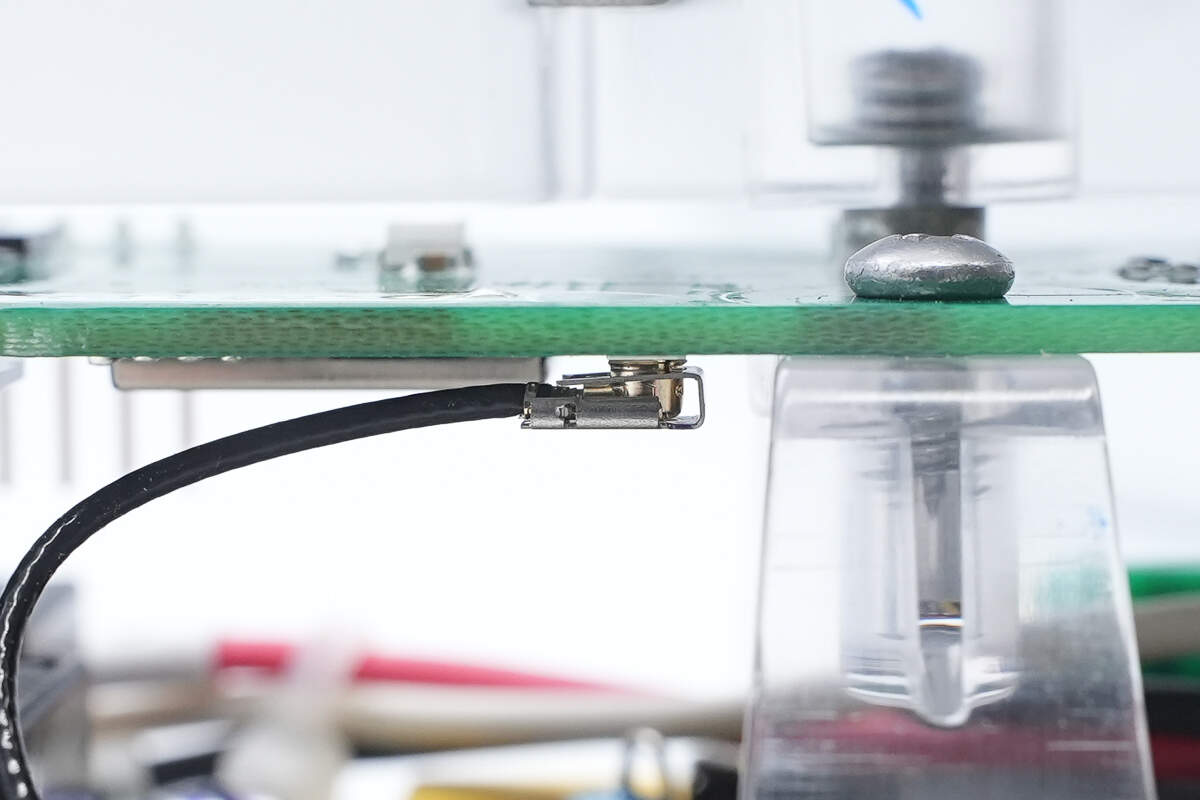
The coaxial feedline is connected to the antenna base.
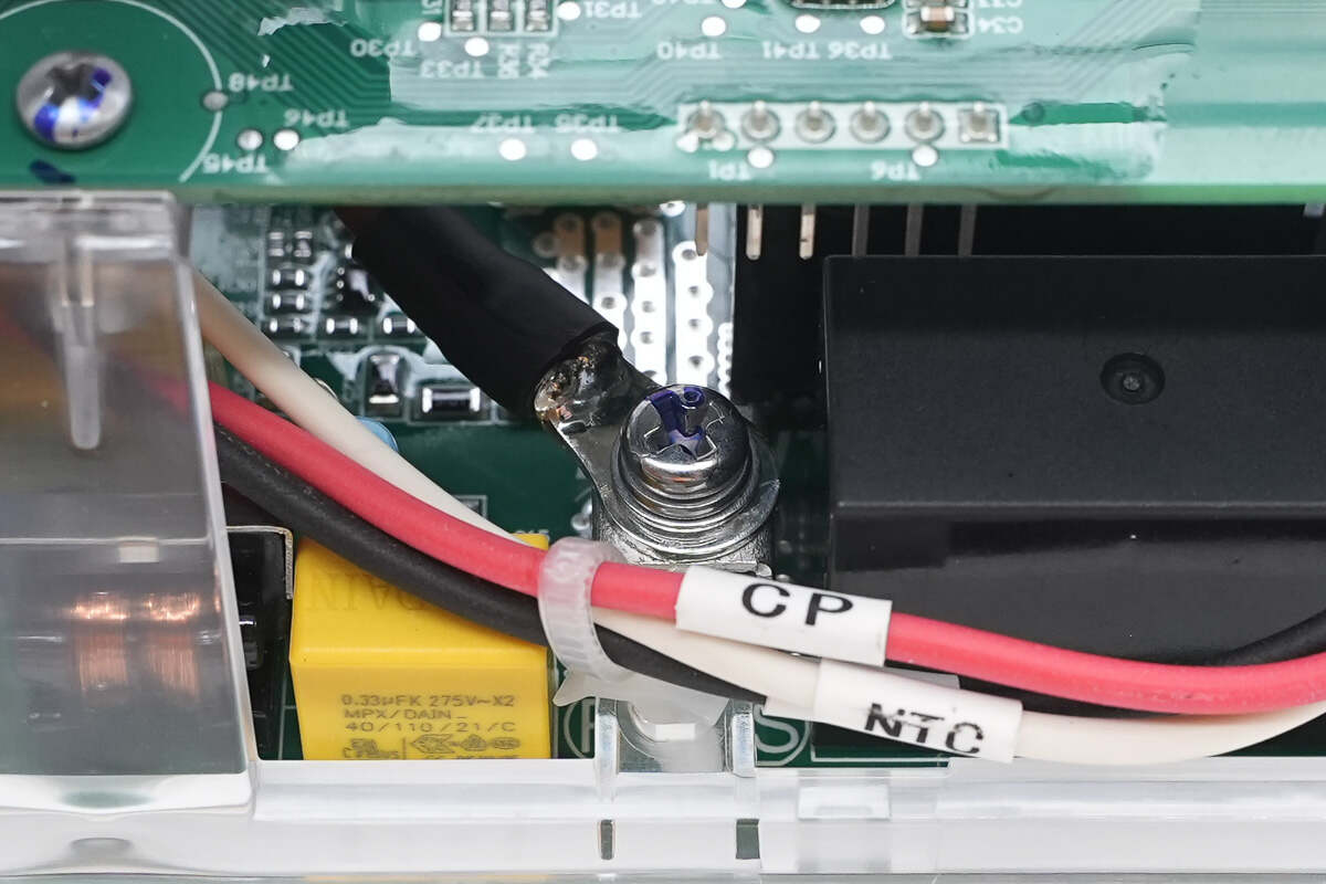
The connecting wires are attached to the PCBA module via screw terminals. The wire ends are crimped and then soldered for added reliability.
The signal wires are connected via plug-in connectors.
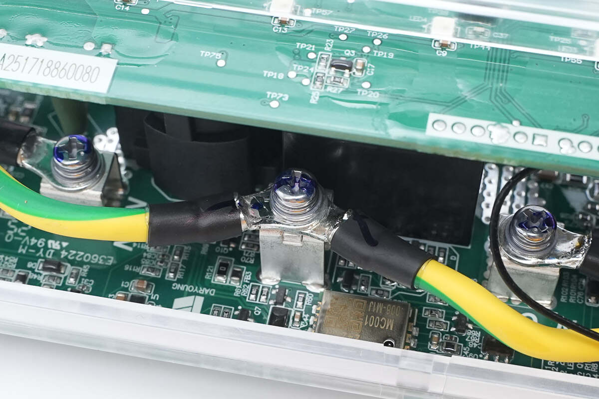
The grounding wire is also connected via a screw terminal.
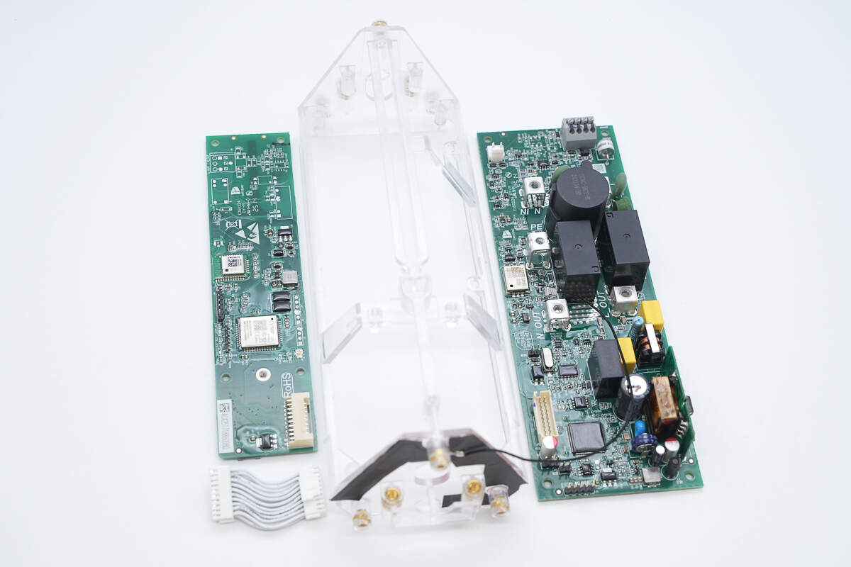
Unscrew the screws to detach the PCBA module from the transparent housing.
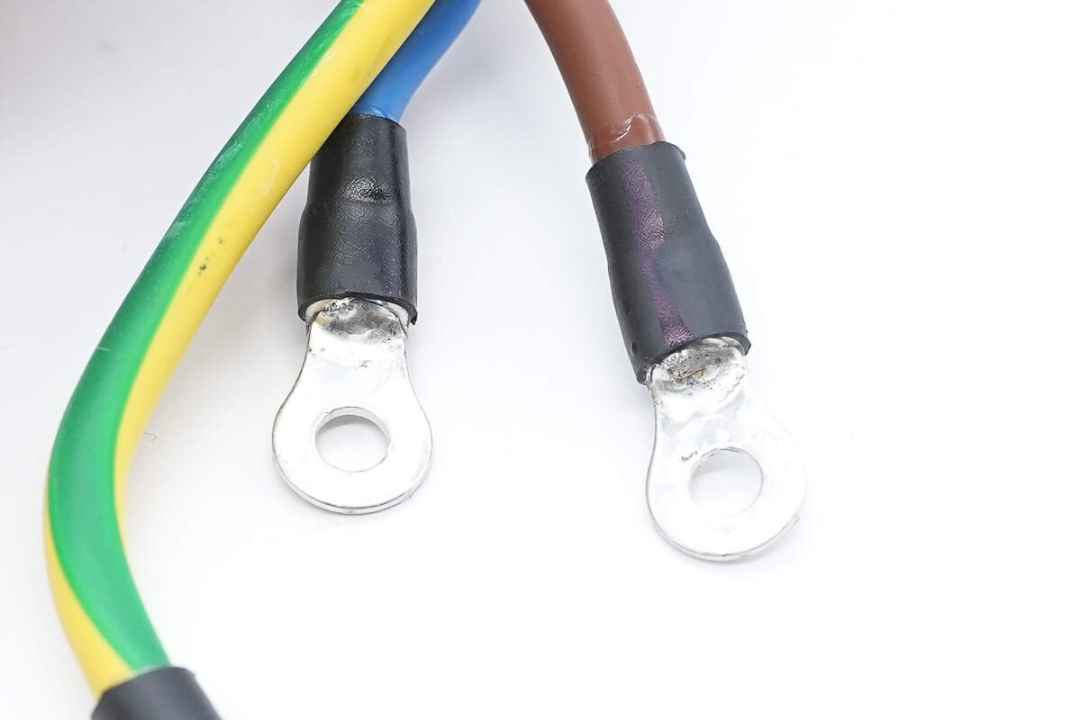
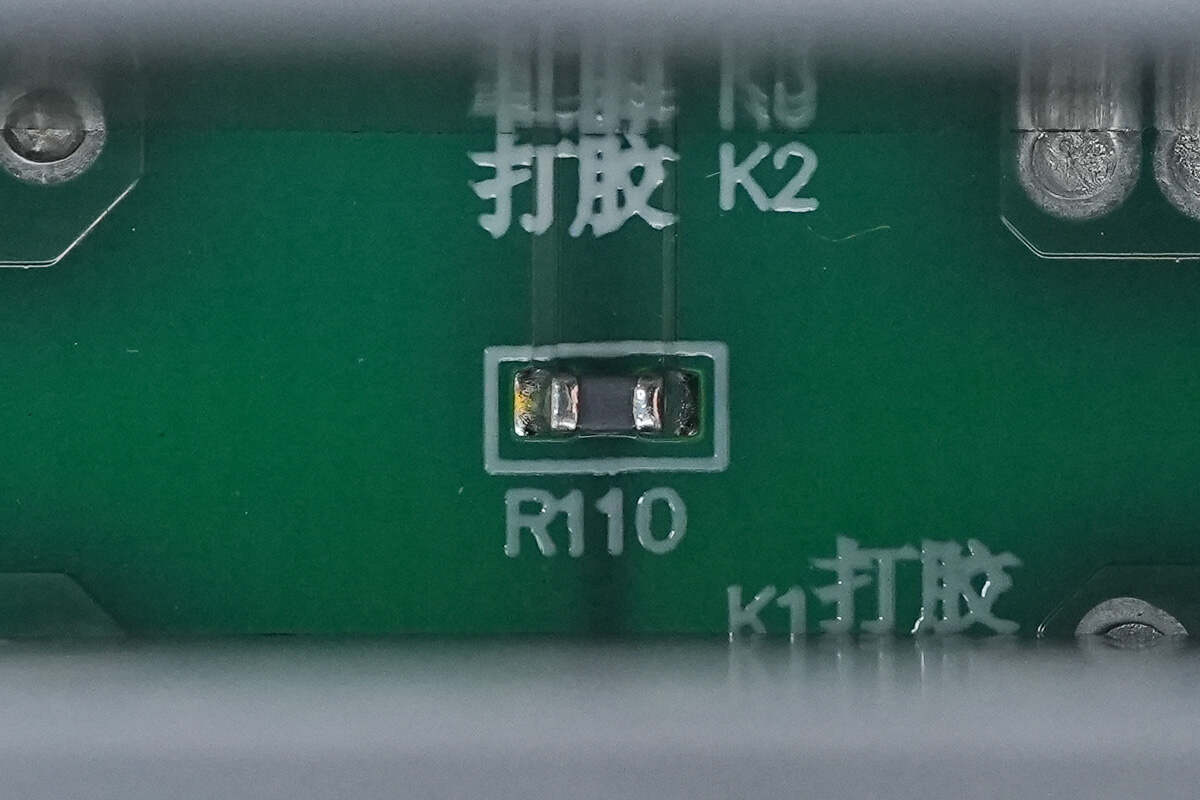
Close-up of the solder filling process at the terminal: after crimping the terminal to the wire, solder is used to fill the gaps, reducing internal resistance, lowering heat generation, and improving mechanical strength and durability.
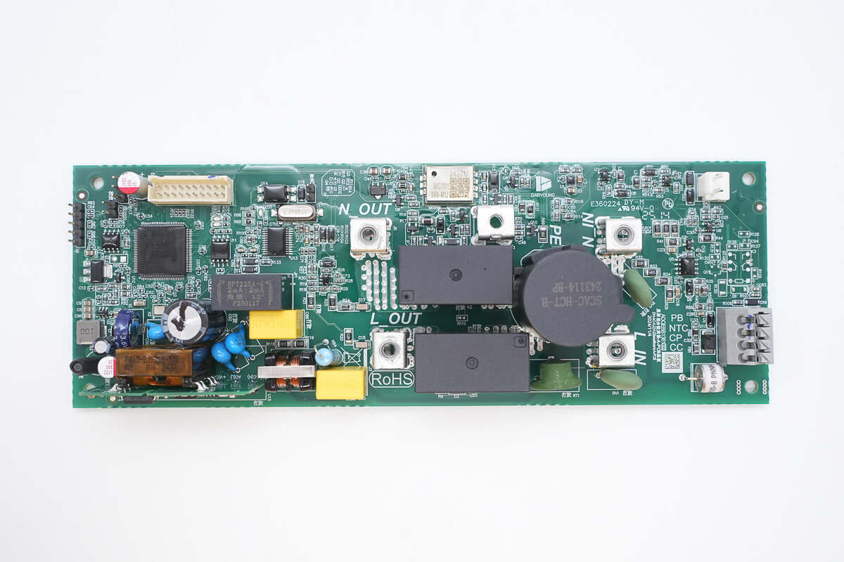
Front view of the PCBA module: the switching power supply module is located in the lower left corner. The upper left houses the MCU and ribbon cable interface. Below and to the right of the MCU is the voltage transformer. Two relays are positioned on the right side of the module. Above the relays is the leakage protection module. To the right of the relays is the current transformer, with a varistor below it and terminal blocks and a gas discharge tube on its right.
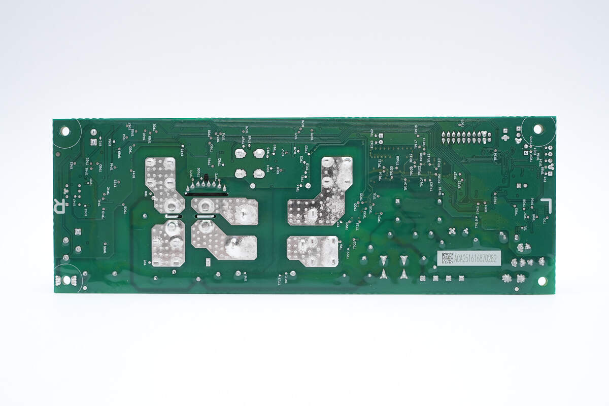
The back side contains no components.
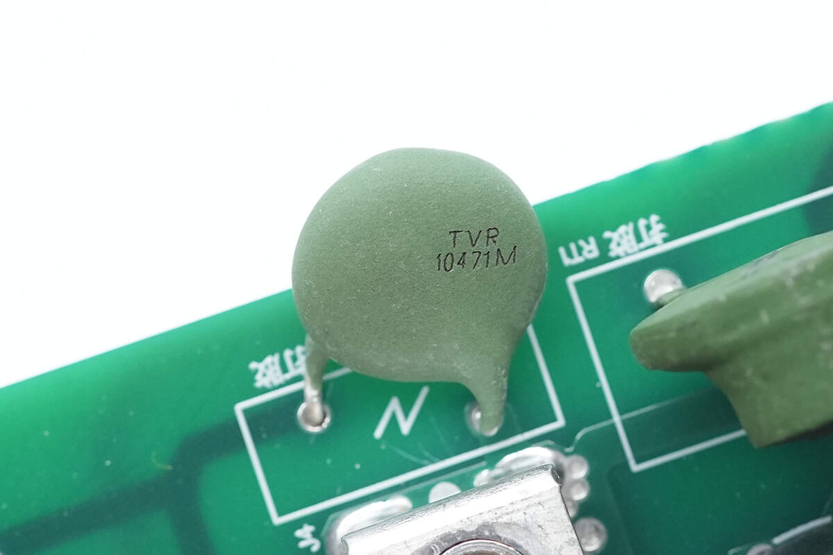
The varistor at the AC input is sourced from Thinking, model TVR10471M, and is used to absorb overvoltage surges.
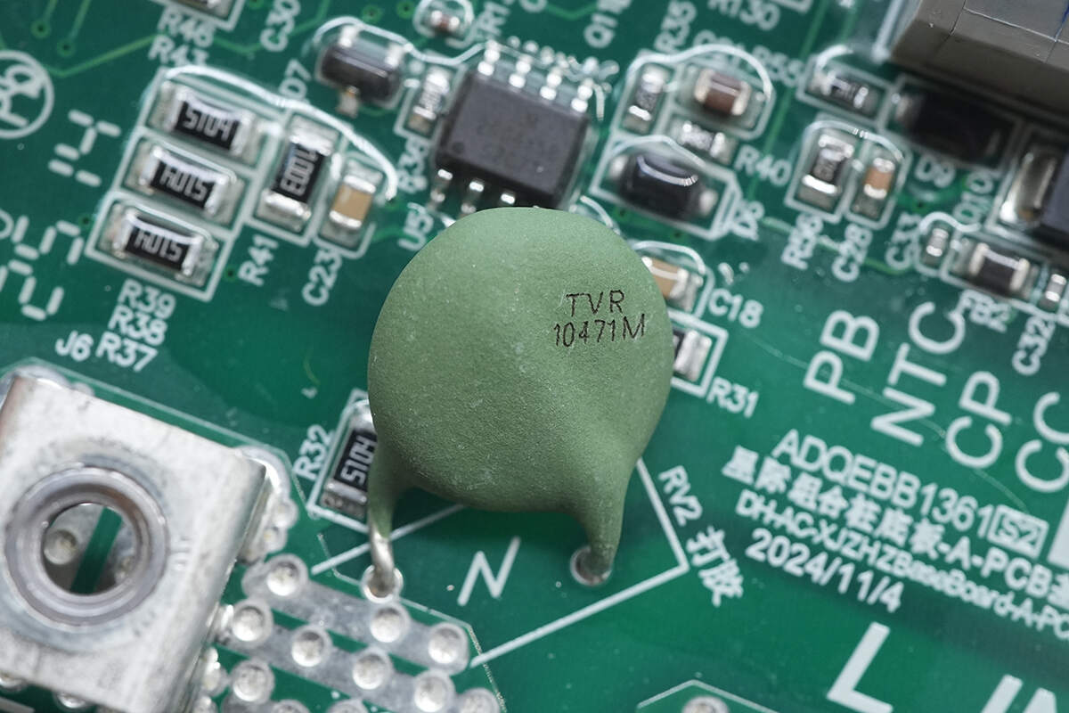
The other varistor is of the same model, TVR10471M.
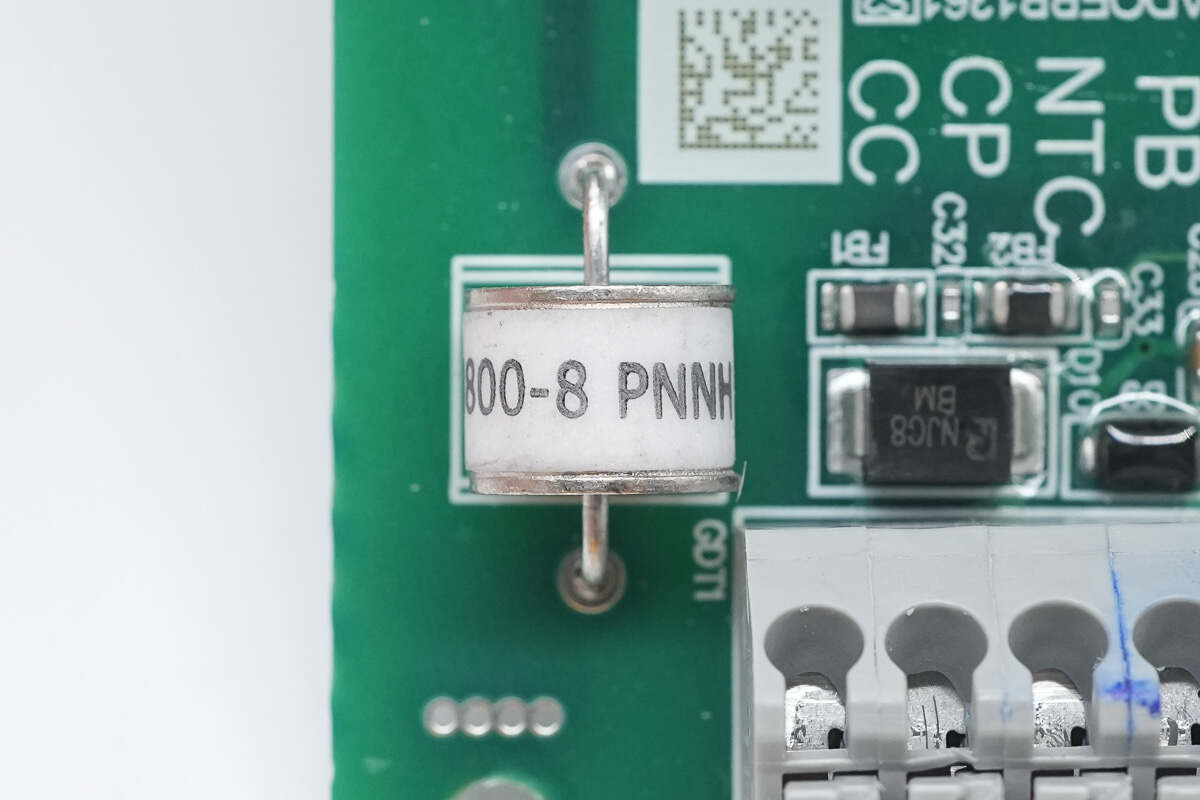
The gas discharge tube is used to absorb overvoltage surges.
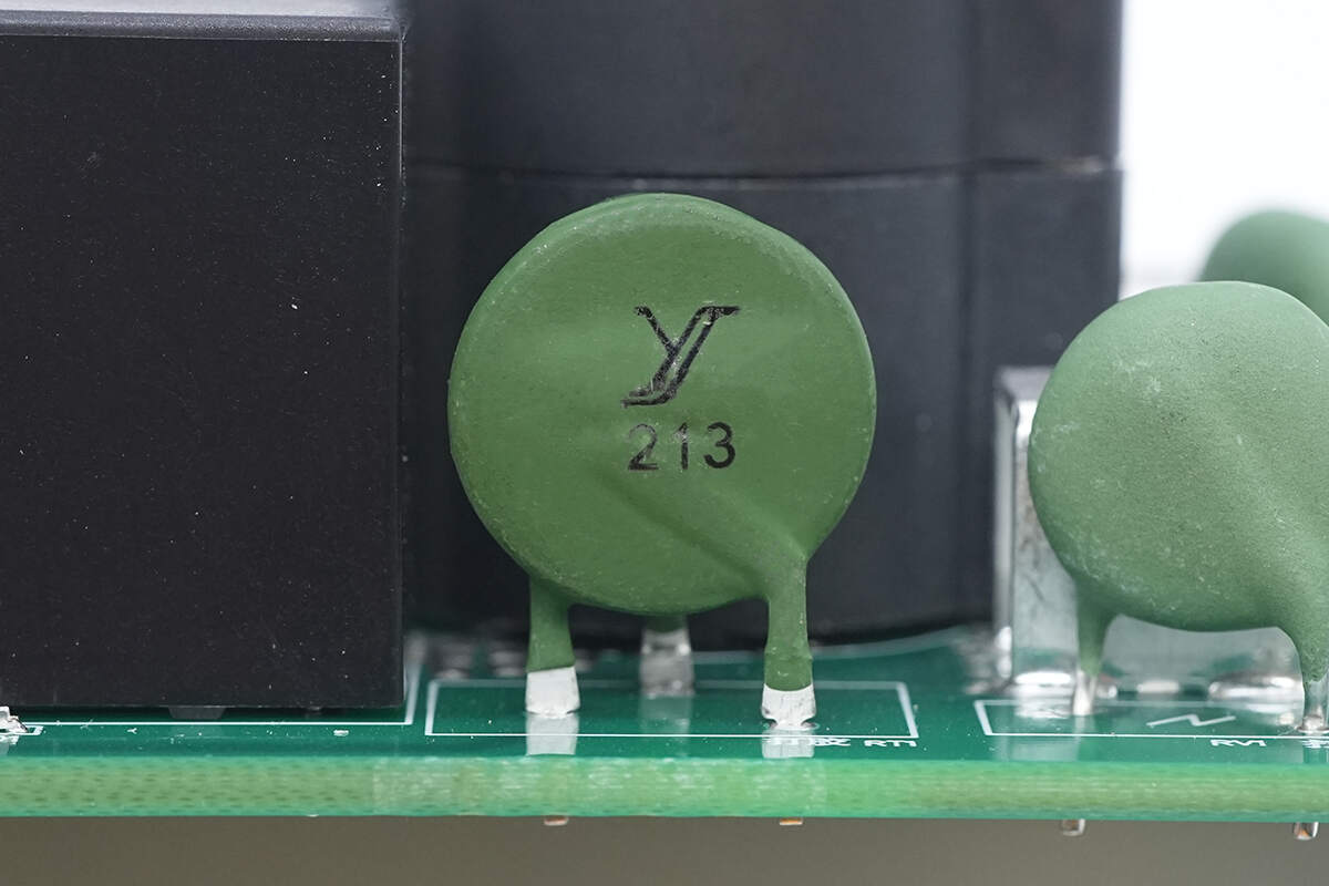
The composite PTC thermistor, sourced from JINYANG and marked with "213", protects against overvoltage, overcurrent, and overheating.
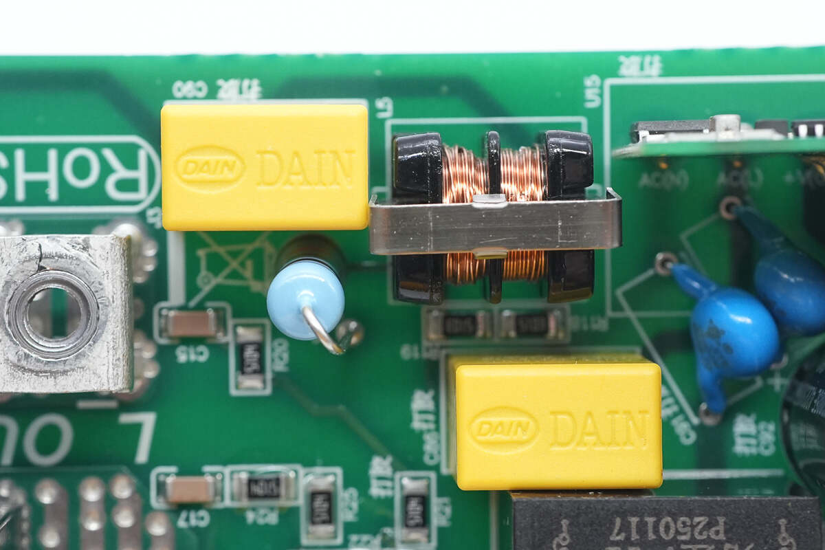
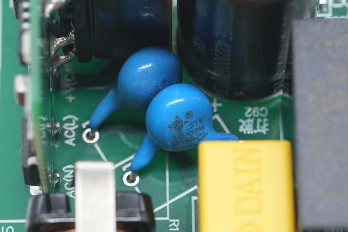
Close-up of the input-side safety X2 capacitors and common mode choke.
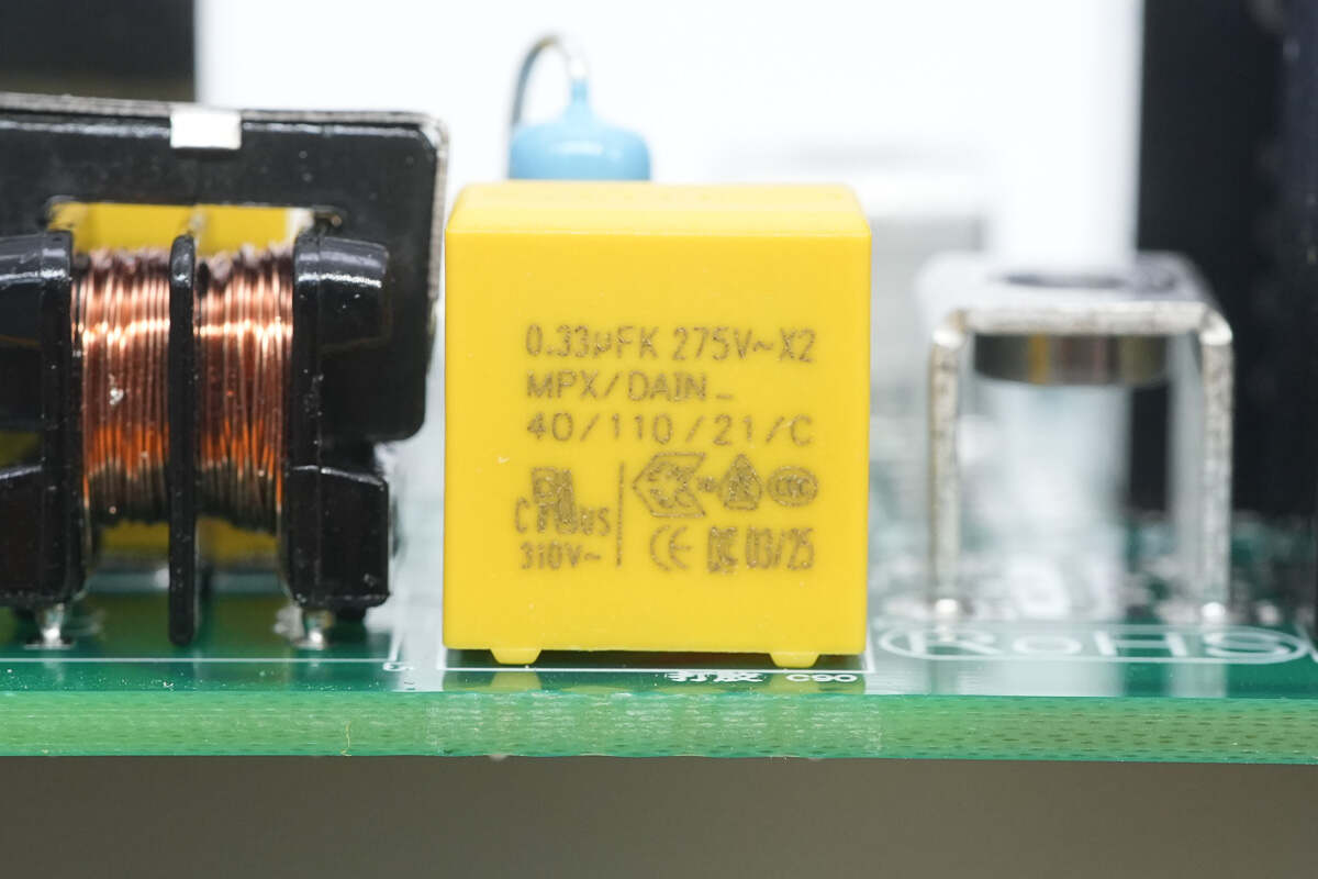
The two safety X2 capacitors are sourced from Dain, each with a specification of 0.33 μF.
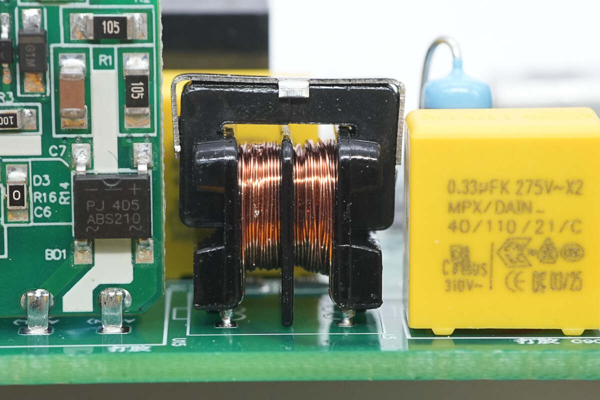
The common mode choke is wound on an insulated bobbin.
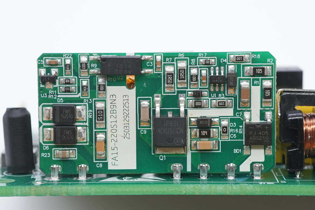
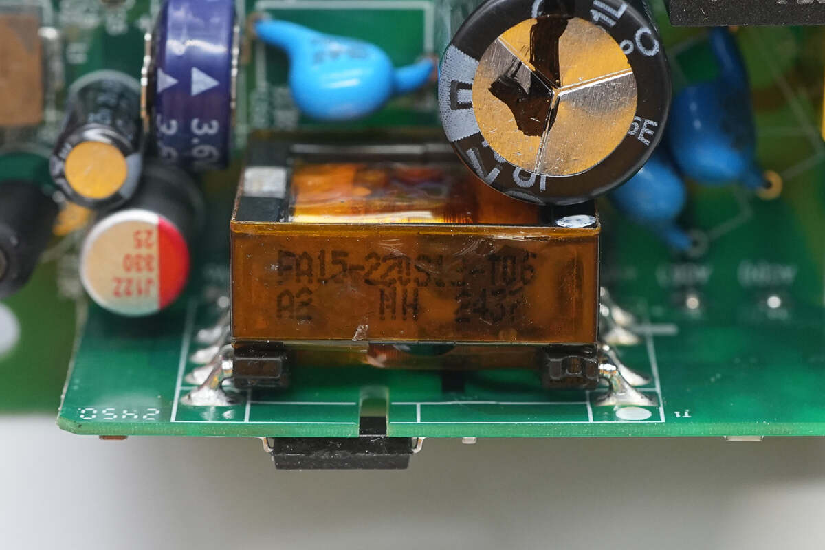
The switching power supply module is sourced from AIPUPOWER, model FA15-220S12B9N3. It supports an input range of 85–305 VAC or 120–430 VDC, delivers an output power of 15 W at 12 V, operates at a switching frequency of 65 kHz, and includes short-circuit and overcurrent protection.
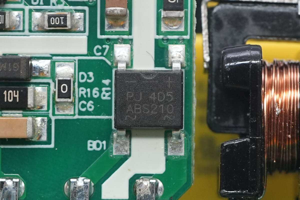
The bridge rectifier is sourced from PANJIT, model ABS210, rated at 2A and 1000V, and uses an ABS package.
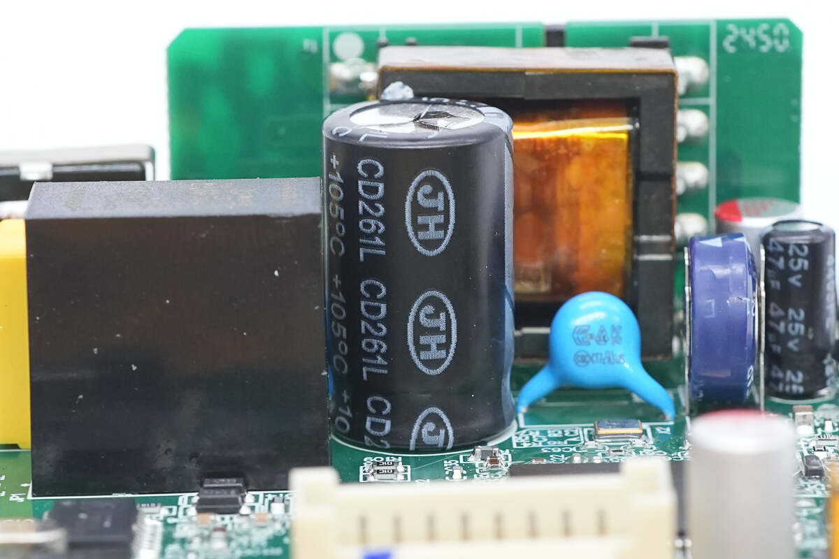
The high-voltage filter capacitor is sourced from Jianghai and belongs to the CD261L series of ultra-long-life electrolytic capacitors.
The capacitor is rated at 450 V, 27 μF.
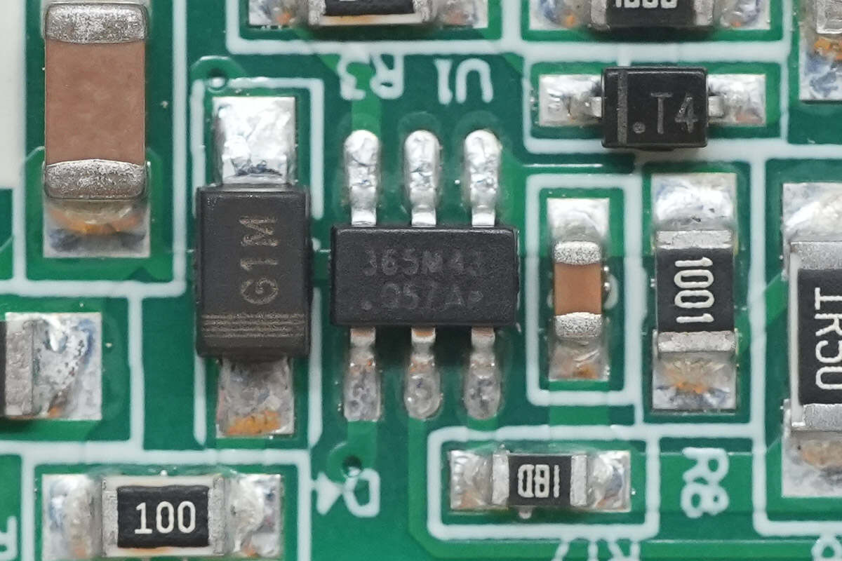
The master control chip is the OB2365 from On-Bright. It is an adaptive multi-mode PWM controller that supports QR, CCM, and burst mode operation. The chip integrates comprehensive protection features and is housed in a compact SOT23-6 package.
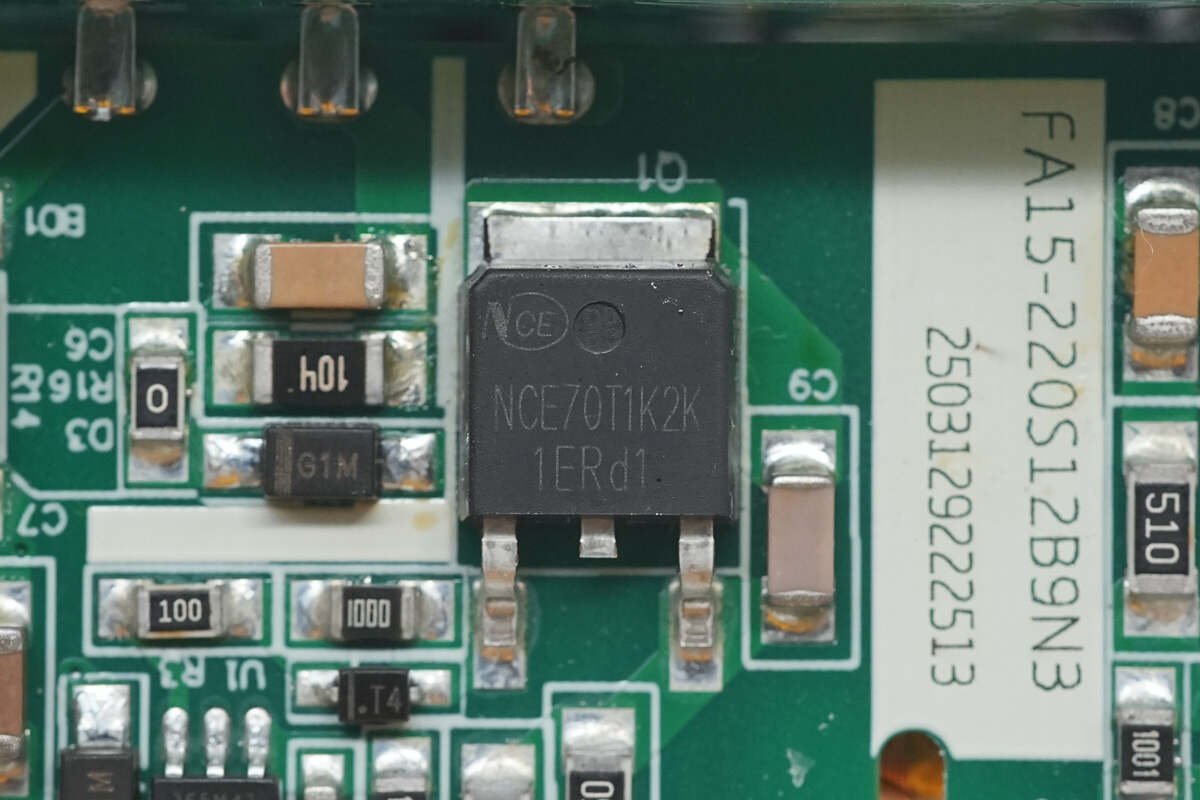
The MOSFET is sourced from NCE, model NCE70T1K2K. It is an N-channel MOSFET with a voltage rating of 700V and an on-resistance of 1100 mΩ. The device is packaged in a TO-252 package.
The transformer is tightly wound and insulated using high-temperature adhesive tape.
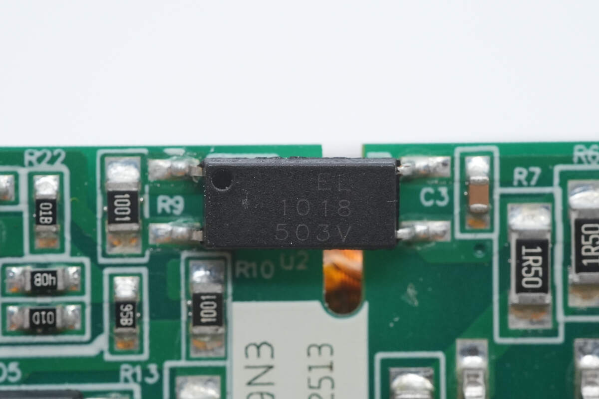
The Everlight EL1018 optocoupler is used for output voltage feedback.
Two blue Y capacitors are sourced from STE, part number CD102M, with a specification of 1000 pF each.
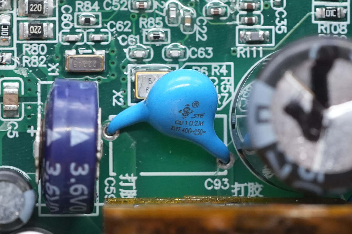
The other blue Y-capacitor has the same specification of 1000 pF.
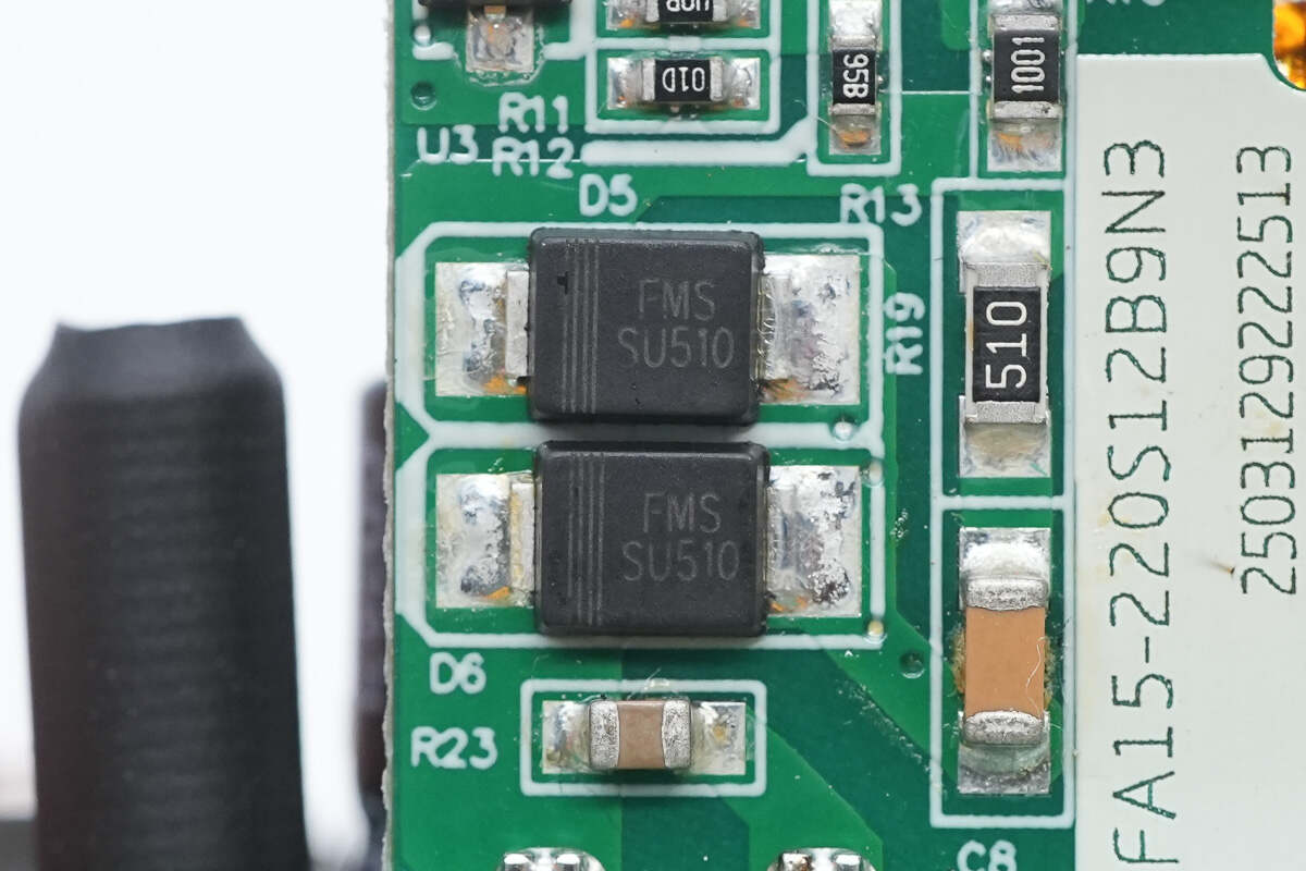
The output rectifier is from FMS, model FU510. It is an ultra-low forward voltage drop Schottky diode rated at 5A and 100V, housed in an SMAF package.
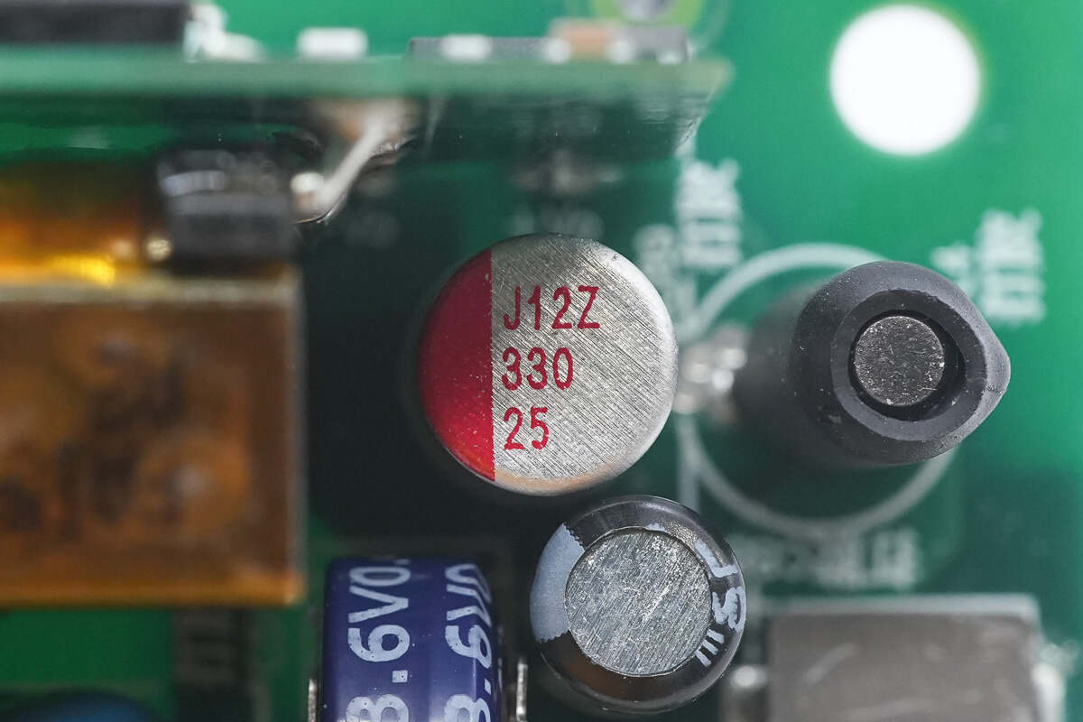
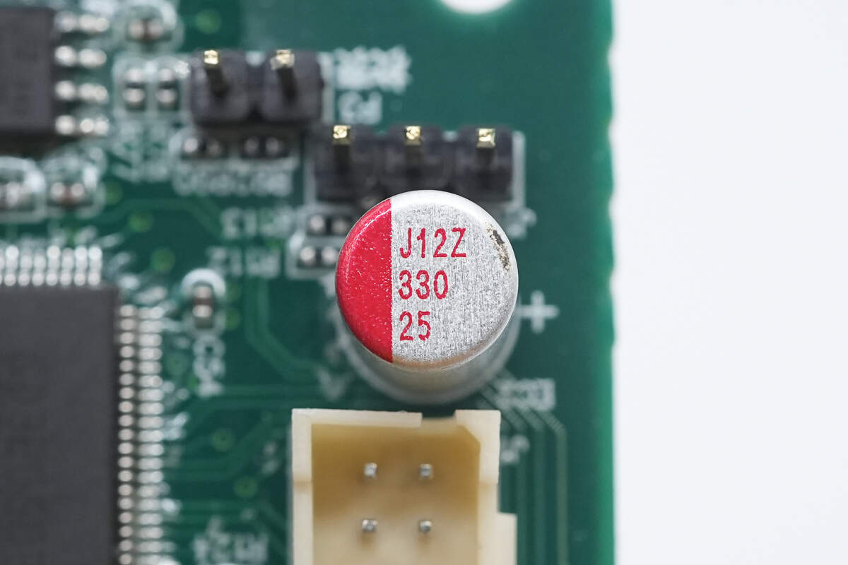
The solid capacitor is rated at 330μF 25V.
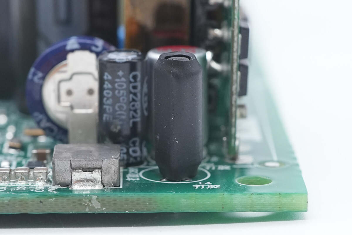
The filter inductor is insulated with heat-shrink tubing.
The output filter capacitor is sourced from Jianghai.
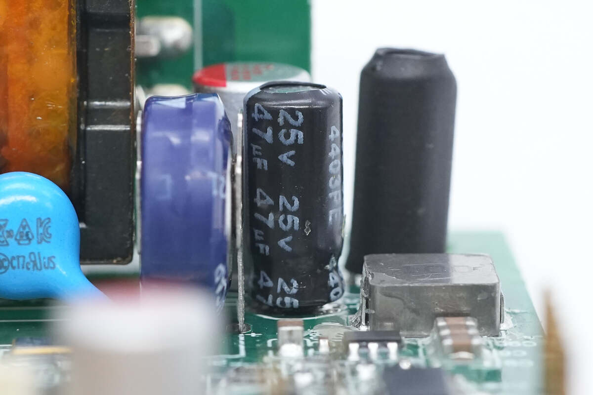
The output filter capacitor from Jianghai is rated at 47μF 25V.
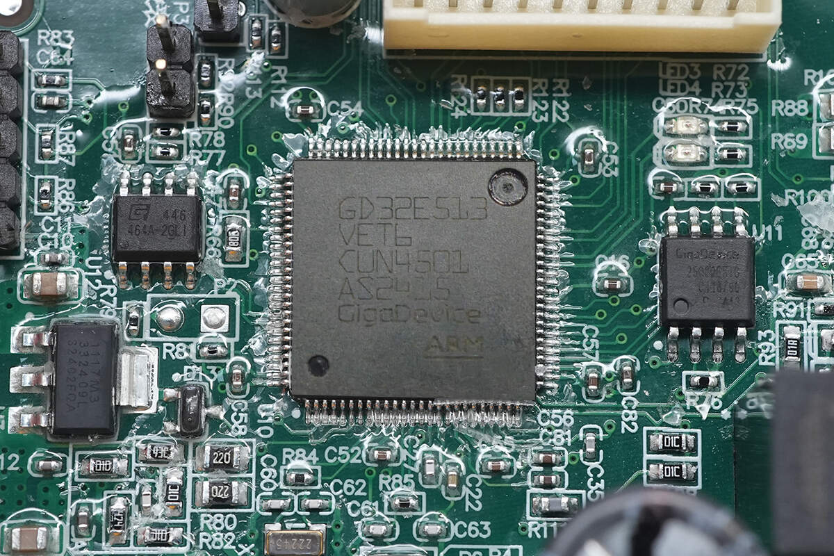
The MCU is from GigaDevice, model GD32E513VET6. It features an integrated 32-bit Cortex-M33 core running at 180 MHz, with 512 KB of FLASH and 128 KB of SRAM. The microcontroller supports multiple communication interfaces, including I²C, SPI, I²S, CAN 2.0B, and USB 2.0. It is housed in an LQFP100 package.
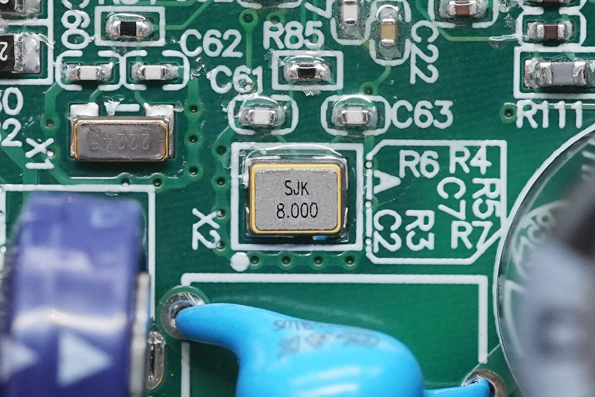
Close-up of the 8.000MHz clock crystal oscillator.
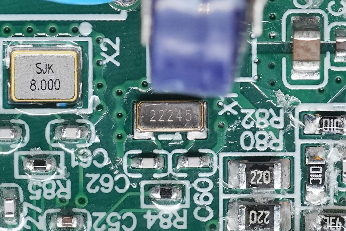
Close-up of the 32.768kHz clock crystal oscillator.
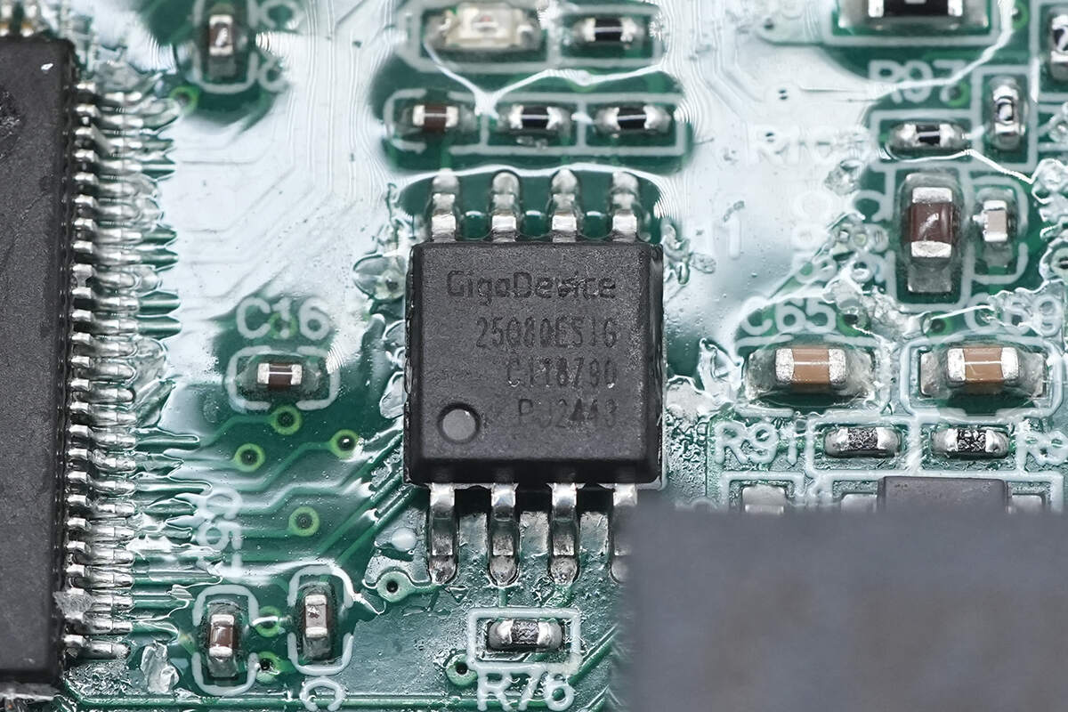
The memory chip is from GigaDevice, model GD25Q80E, with a capacity of 1MB. It is packaged in an SOP8 form factor.
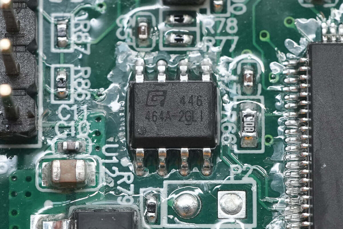
The other memory chip is an EEPROM, model GT24C64A, with a capacity of 8KB, housed in an SOP8 package.
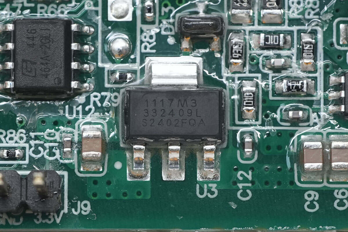
The 1117 voltage regulator is used to supply power to the MCU.
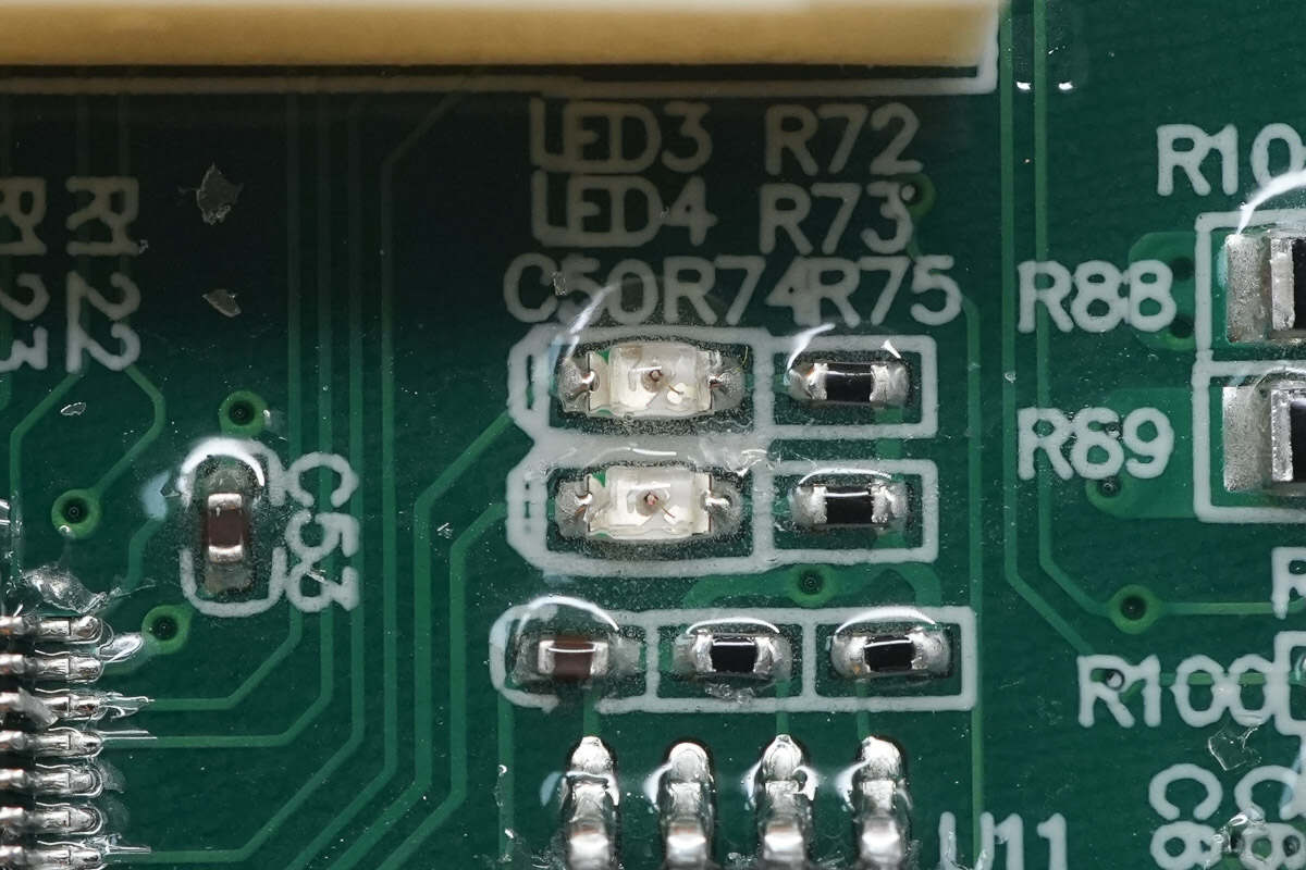
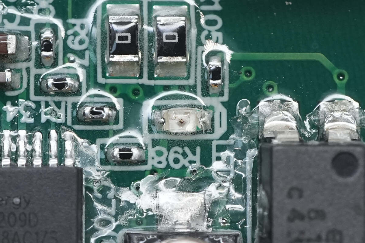
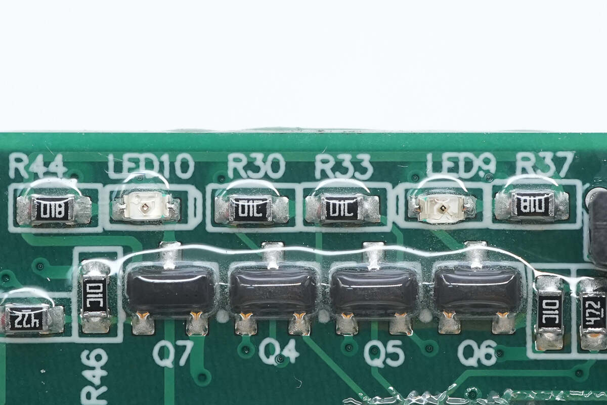
Two LEDs are used for status indication.
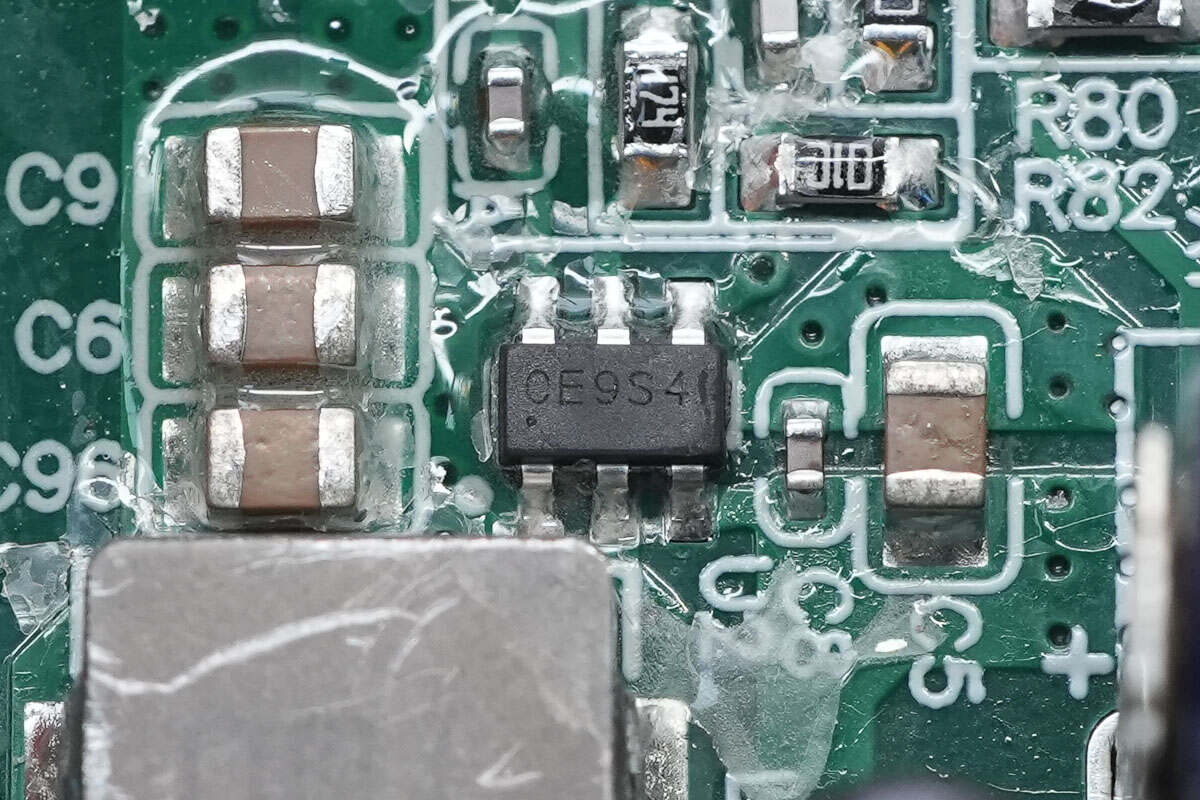
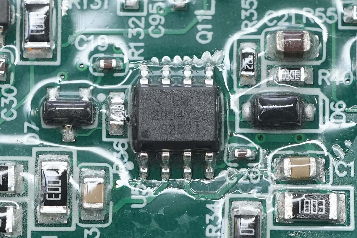
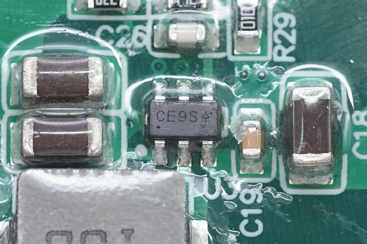
The synchronous buck chip is from SGMICRO, marked with CE9, model SGM61230. It is a synchronous step-down converter with a 28V input voltage rating and 3A output current. The device integrates 66mΩ and 36mΩ MOSFETs, and features output overcurrent protection, output overvoltage protection, and thermal shutdown. It comes in a TSOT-23-6 package.
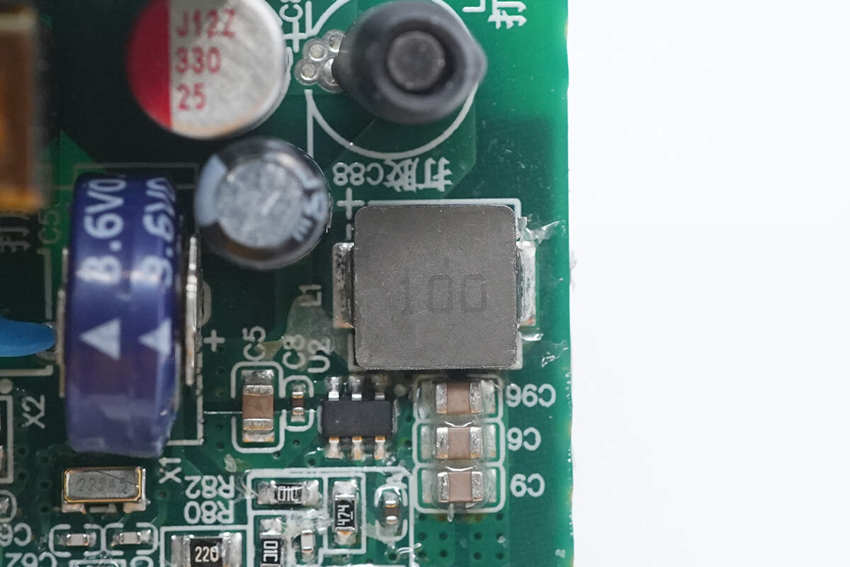
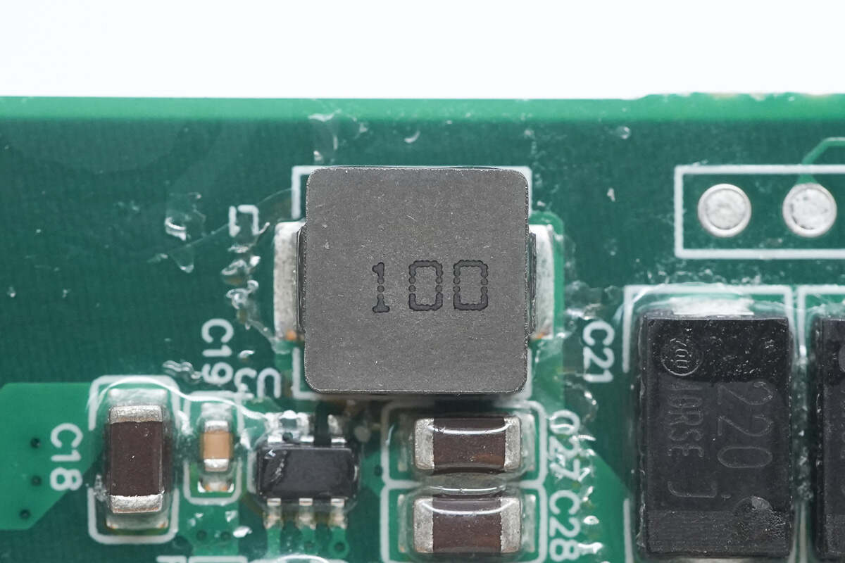
Close-up of the 10μH alloy inductor.
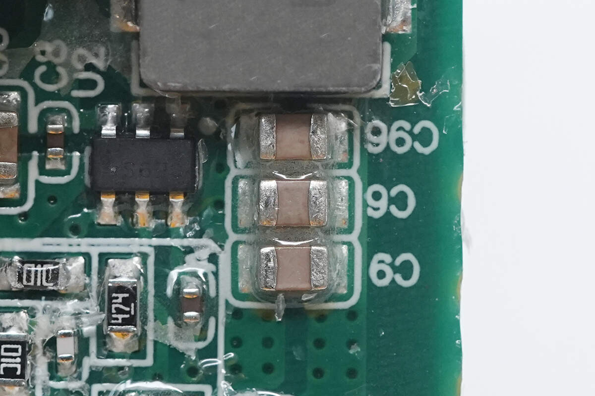
Three MLCC capacitors are connected in parallel for output filtering.
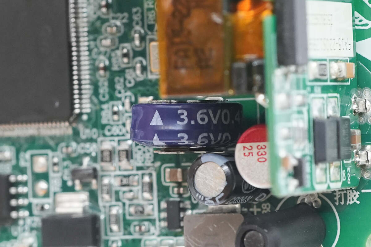
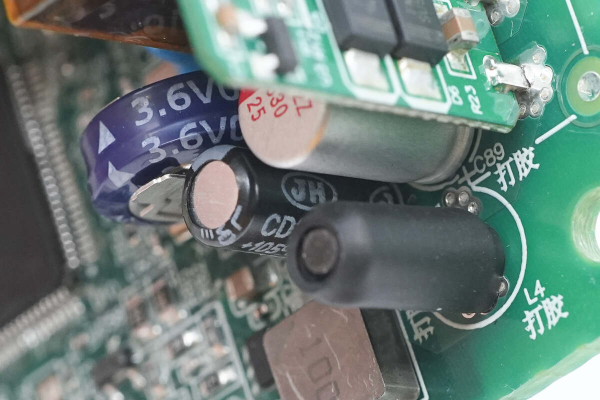
The supercapacitor is rated at 3.6V, 0.47F.
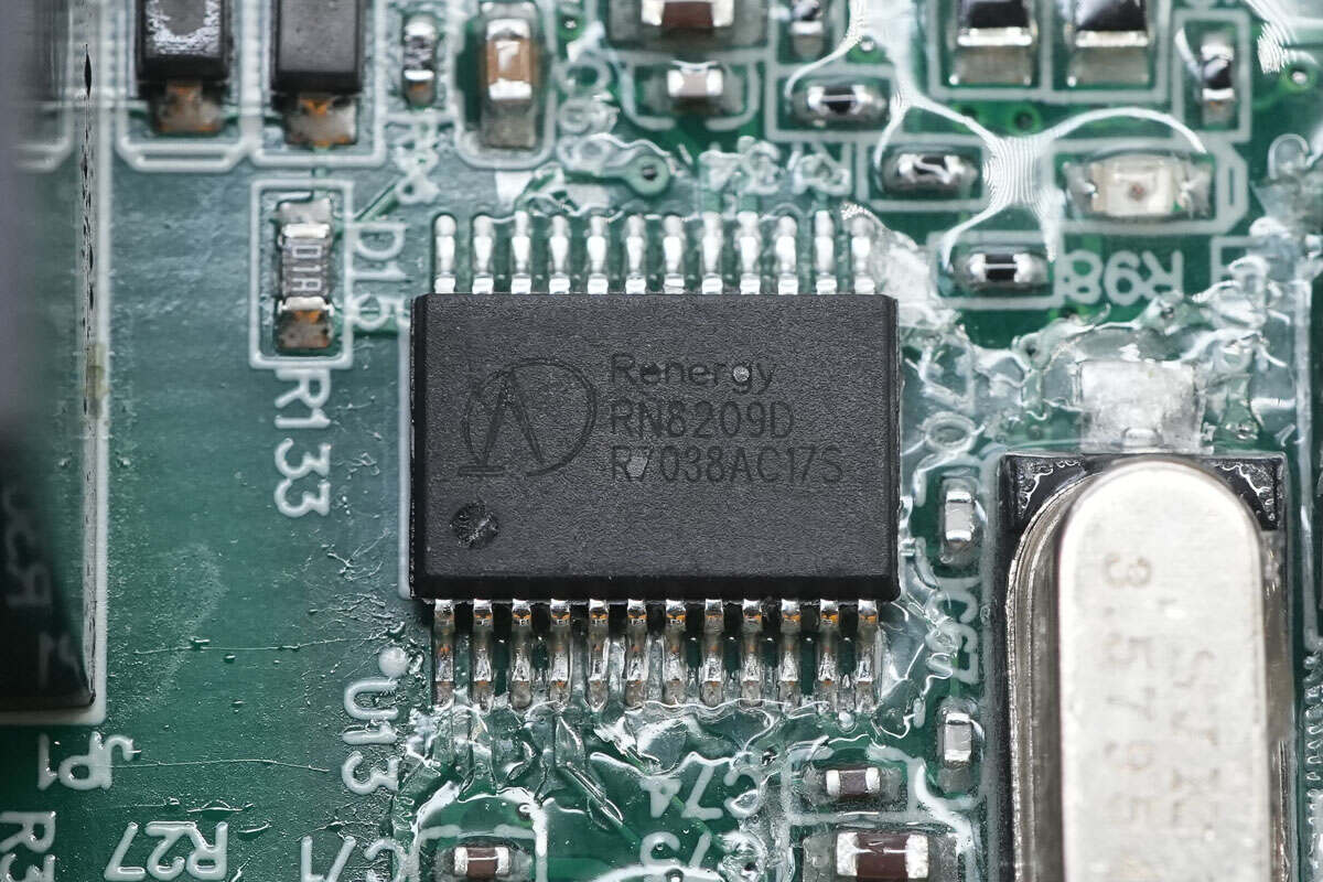
The battery gauge is sourced from RENERGY, model RN8209D. It supports both active and reactive energy metering and provides SPI and UART interfaces for communication with the MCU. The device comes in an SSOP24 package.
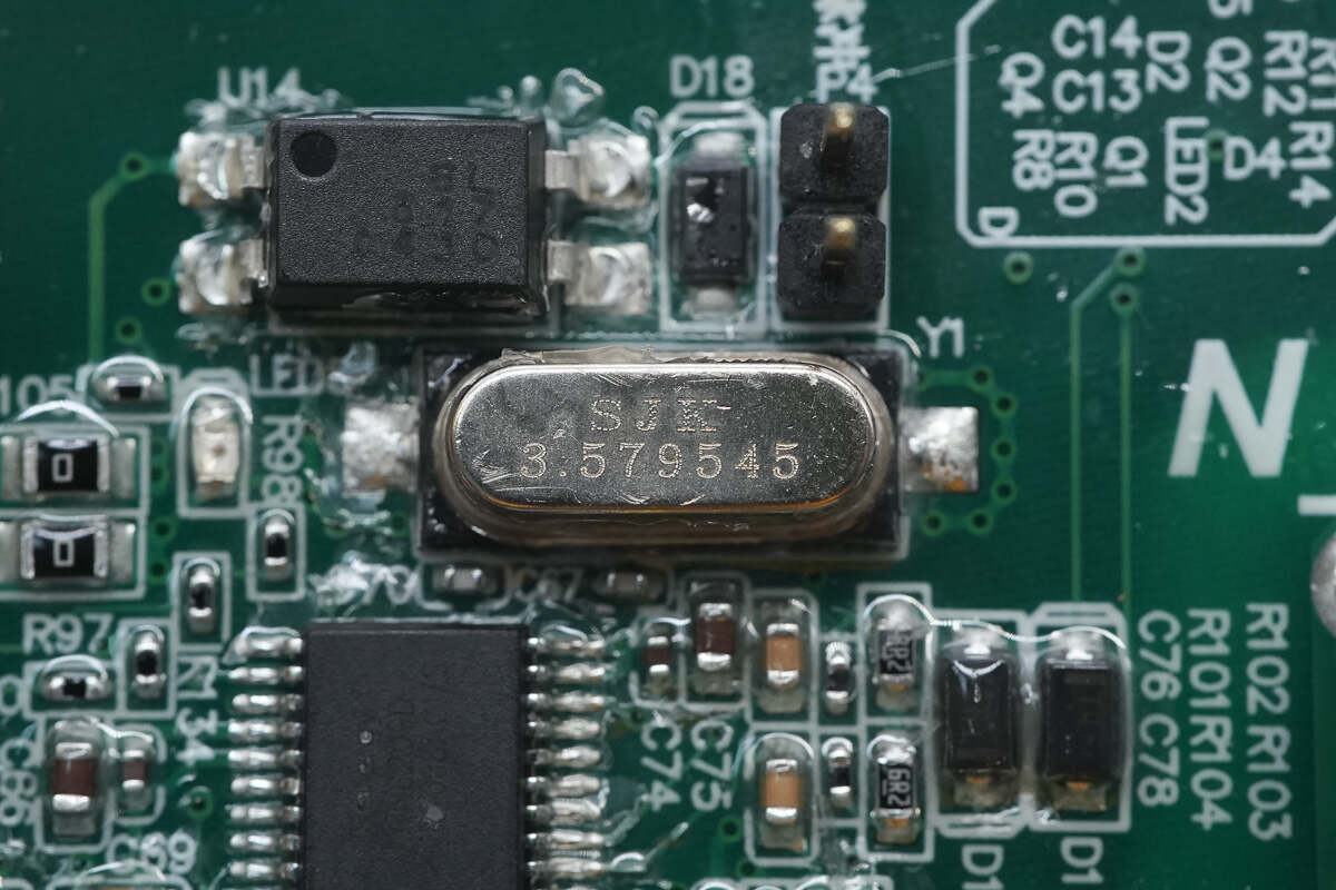
Close-up of the 3.579545MHz clock crystal oscillator.
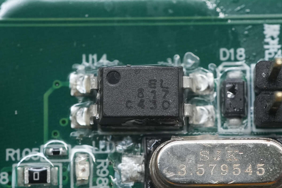
The Everlight EL817 optocoupler is used for pulse signal output.
The LED is used for pulse signal indication.
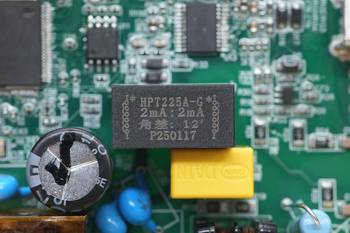
The voltage transformer is from HOP, model HPT225A-G. It is a precision current-type voltage transformer used for AC input voltage detection in charging stations.
Close-up of the resistor connected in series with the voltage transformer.
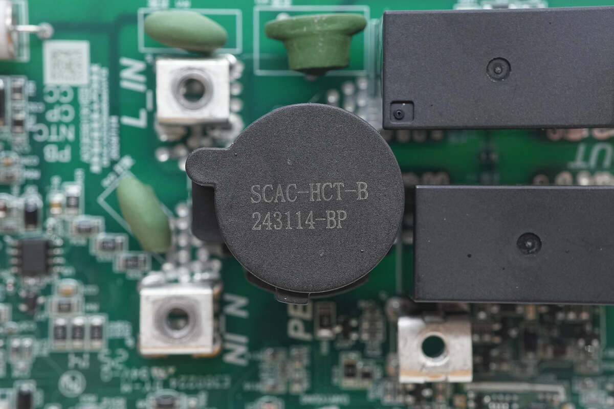
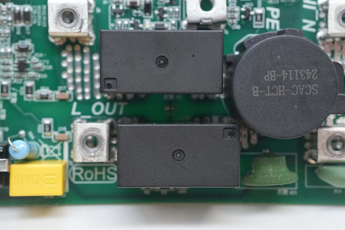
The integrated current transformer, marked with SCAC-HCT-B, is used for detecting charging current and leakage current.
The leakage protection module is model MC001 006-M1J.
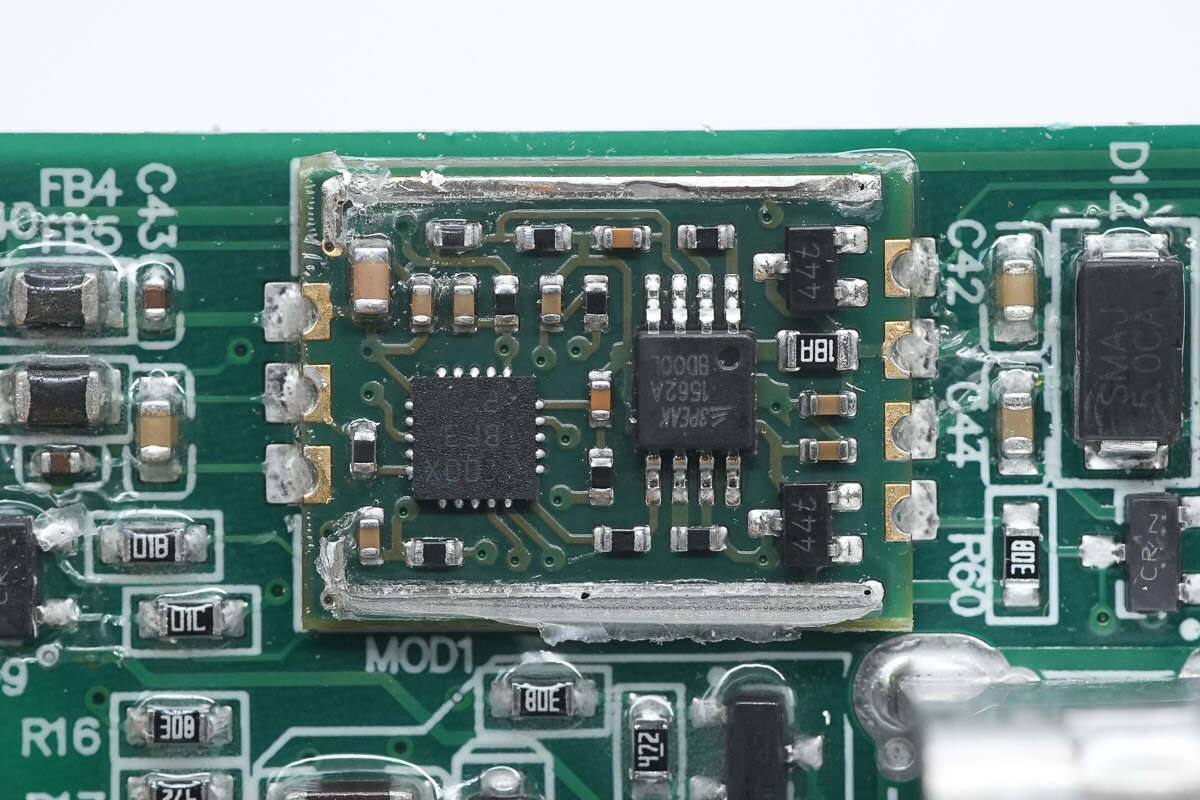
The module contains two built-in chips.
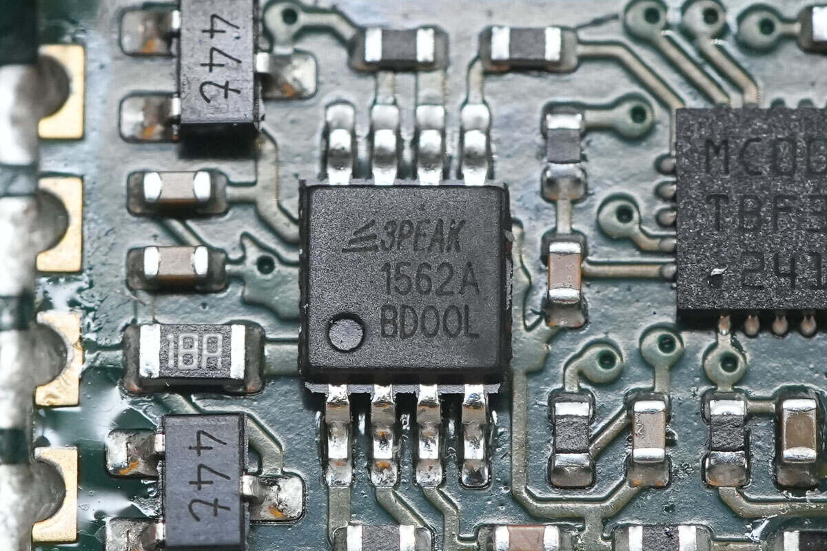
The Op-Amp is from 3PEAK, model TP1562A. It is a dual op-amp featuring rail-to-rail input and output, supports an operating temperature range of -40°C to 125°C, and is packaged in an MSOP8 form factor.
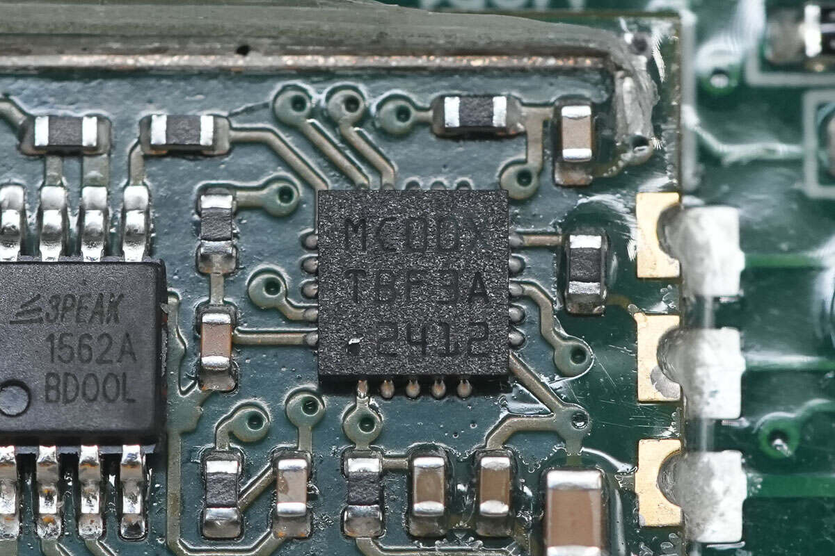
The other chip is marked with MC00XTFB3A.
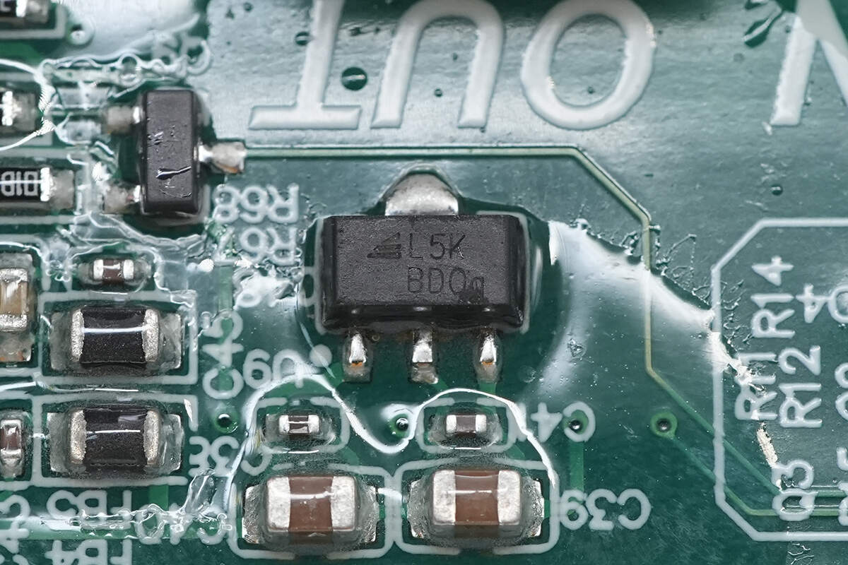
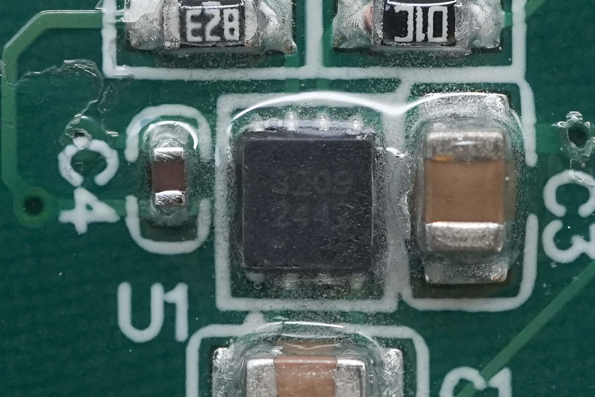
The voltage regulator chip powering the module is from 3PEAK, marked with L5K, model TPL820F20. It supports a 42V input voltage, provides a 5V output voltage with a maximum output current of 200mA, and is housed in an SOT89 package.
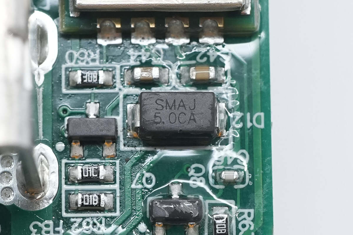
The input is protected against overvoltage by a TVS diode, model SMAJ5.0CA, with a working voltage of 5V.
An NTC thermistor is placed between the two relays.
The NTC thermistor is used for the relay temperature protection function.
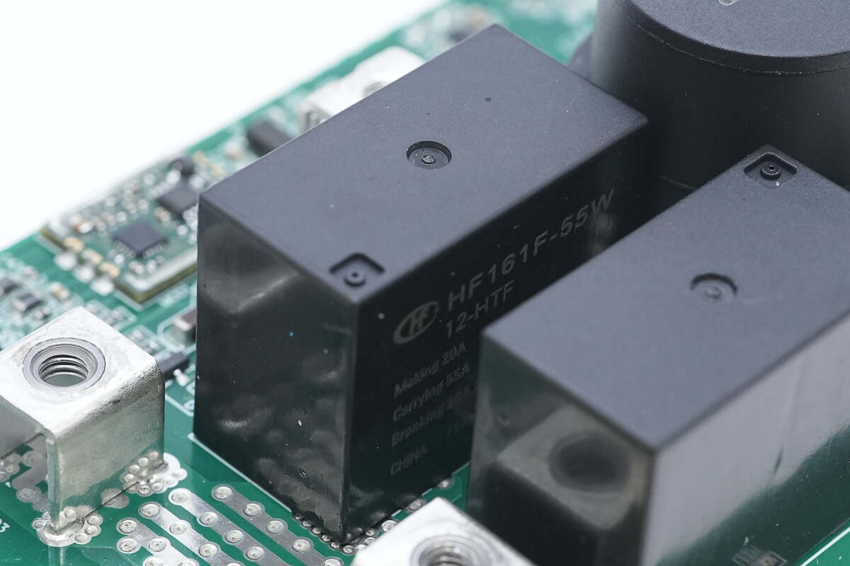
The relay used for controlling the charging output is from HONGFA, model HF161F-55W/12-HTF. It is a compact high-power relay with a single normally open contact, rated for a load capacity of 55A at 277VAC. The coil voltage is 12V.
The SGMICRO LM2904 dual operational amplifier is used for input voltage detection.
The charge pump chip is from SGMICRO, model SGM3209. It is a negative voltage output charge pump that supports up to 18V input voltage and provides an output current of 100mA. The chip is housed in a TDFN 2×2-8L package.
Close-up of the terminal block connected to the upper-layer PCB.
The filter capacitor is rated at 330μF 25V.
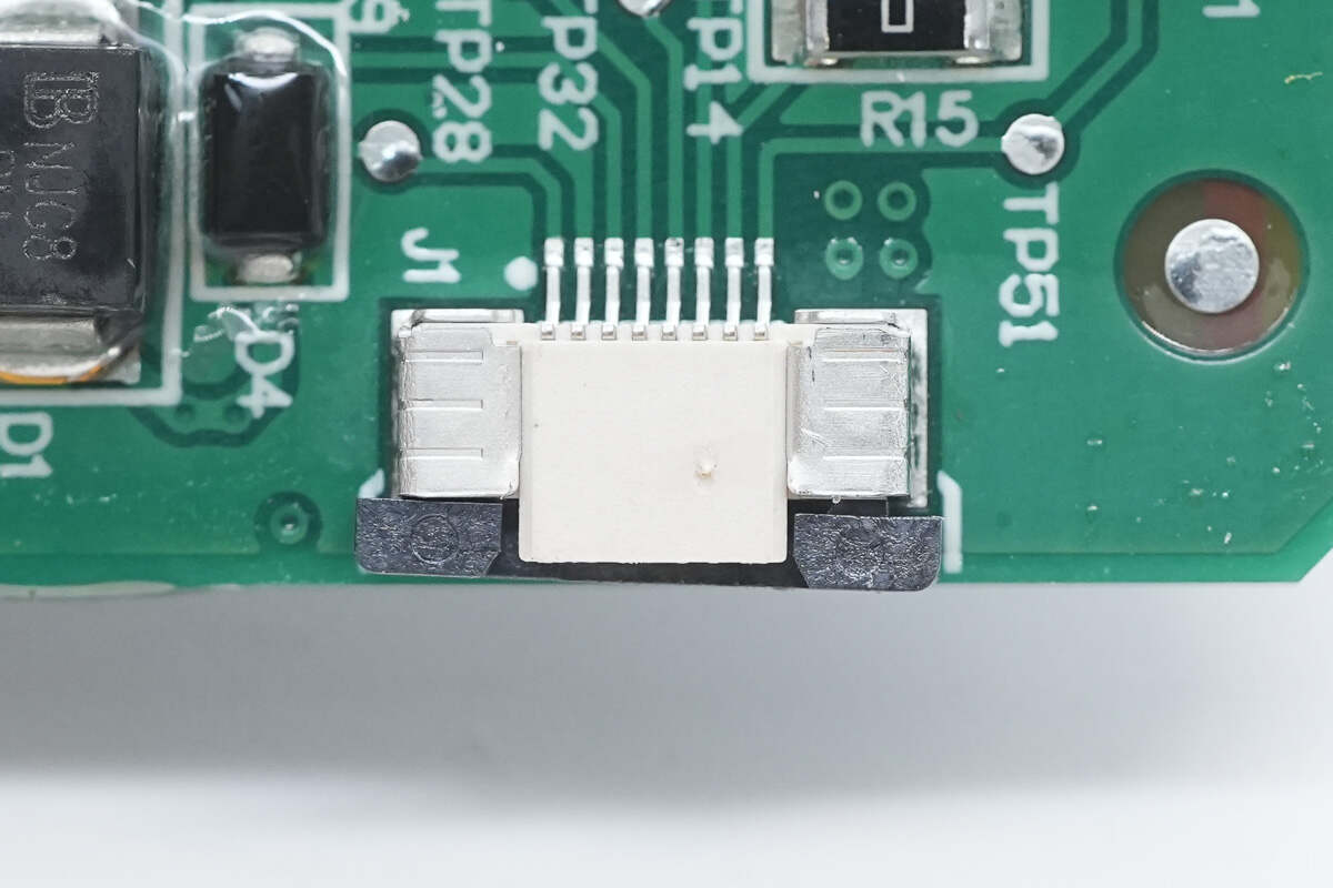
Close-up of the connector used for connecting the charging connector.
The TVS diode is from BrightKing, model SMBJ15CA, with a working voltage of 15V. It is packaged in an SMB form factor.
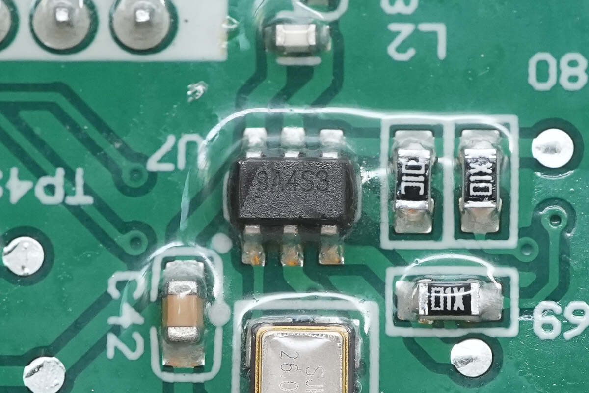
The upper-layer PCB features LED indicators and an eSIM card chip.
On the other side, there is a 4G communication module and a Bluetooth module.
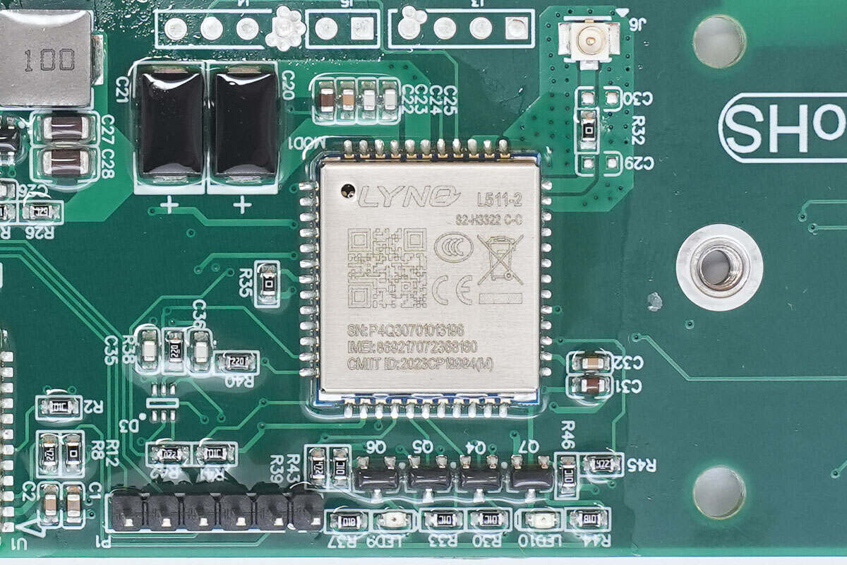
The wireless communication module, model L511-2 from MobileTek, is used for 4G network connectivity in charging stations, enabling remote control functionality via a mobile app.
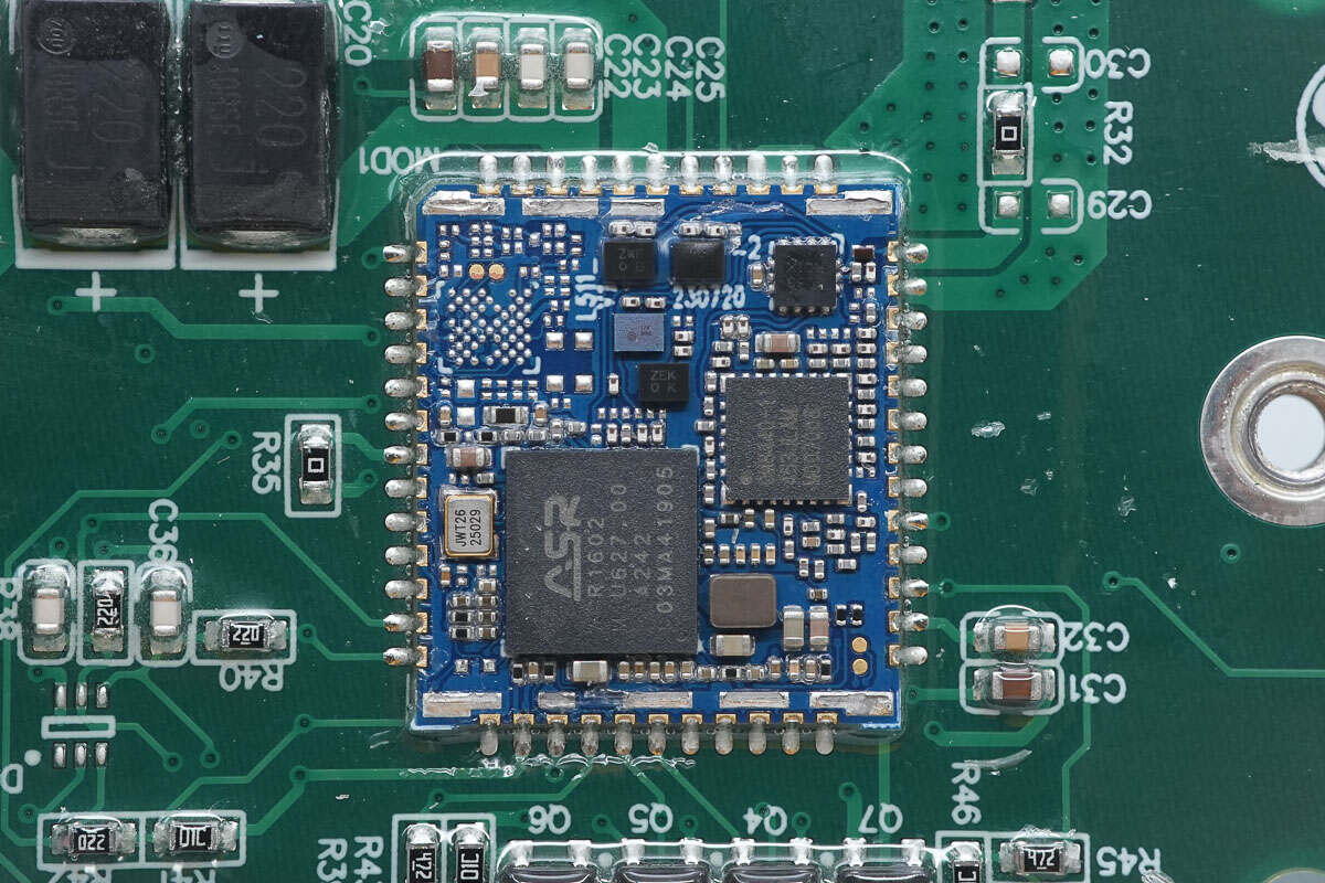
The module contains a master control chip, a power amplifier chip, filters, and an antenna switch.
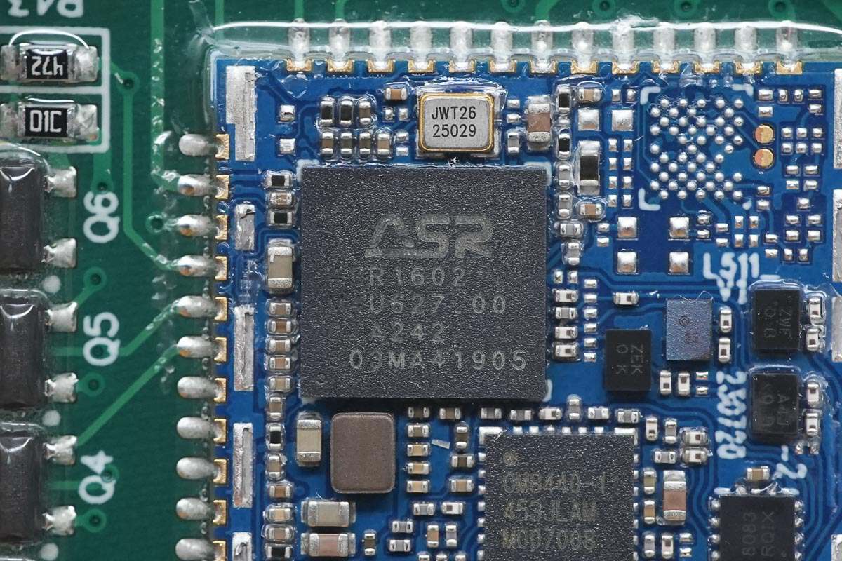
The master control chip is the ASR1602 from ASR, which integrates a processor, memory, and multiple IoT peripheral interfaces. It supports the OpenCPU architecture, reducing development complexity and cost.
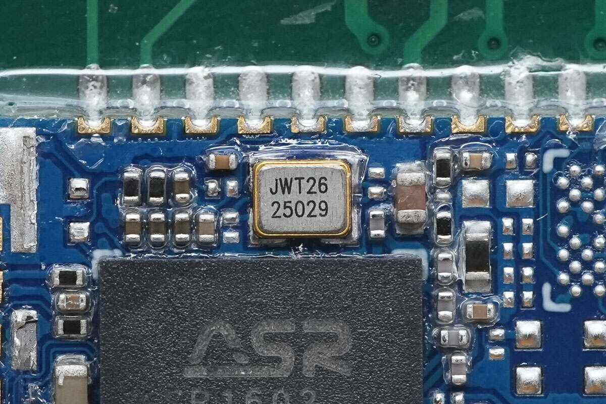
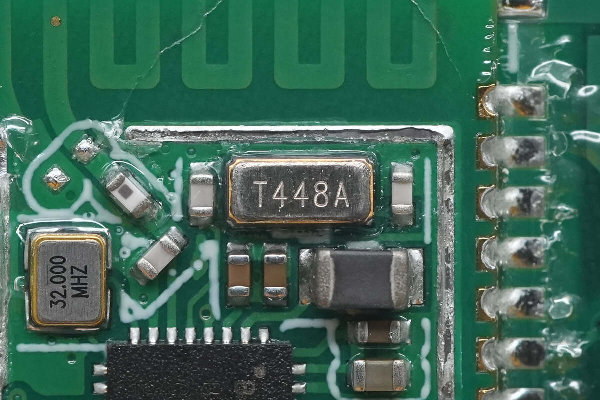
Close-up of the clock crystal oscillator.
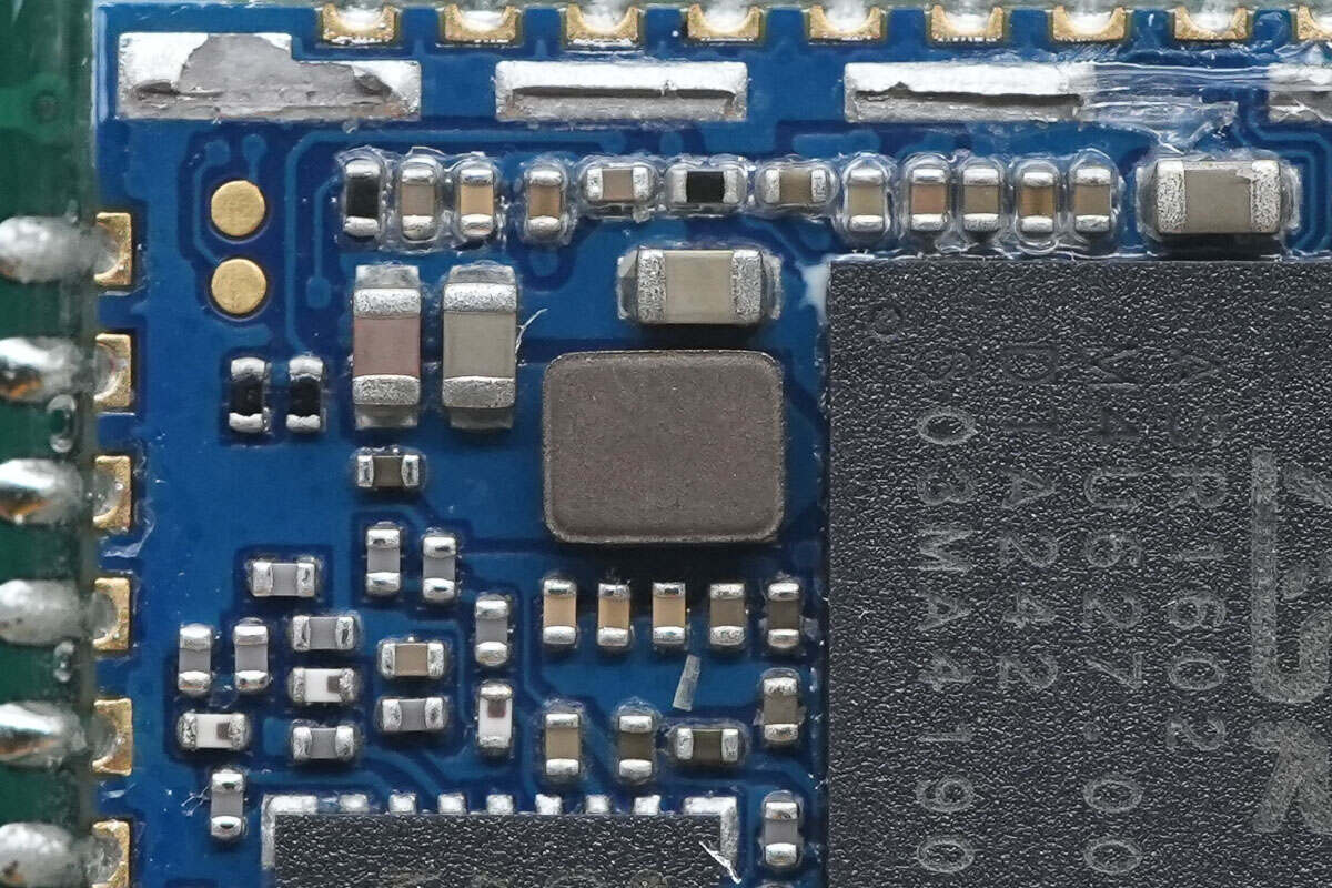
Close-up of the power supply inductor.
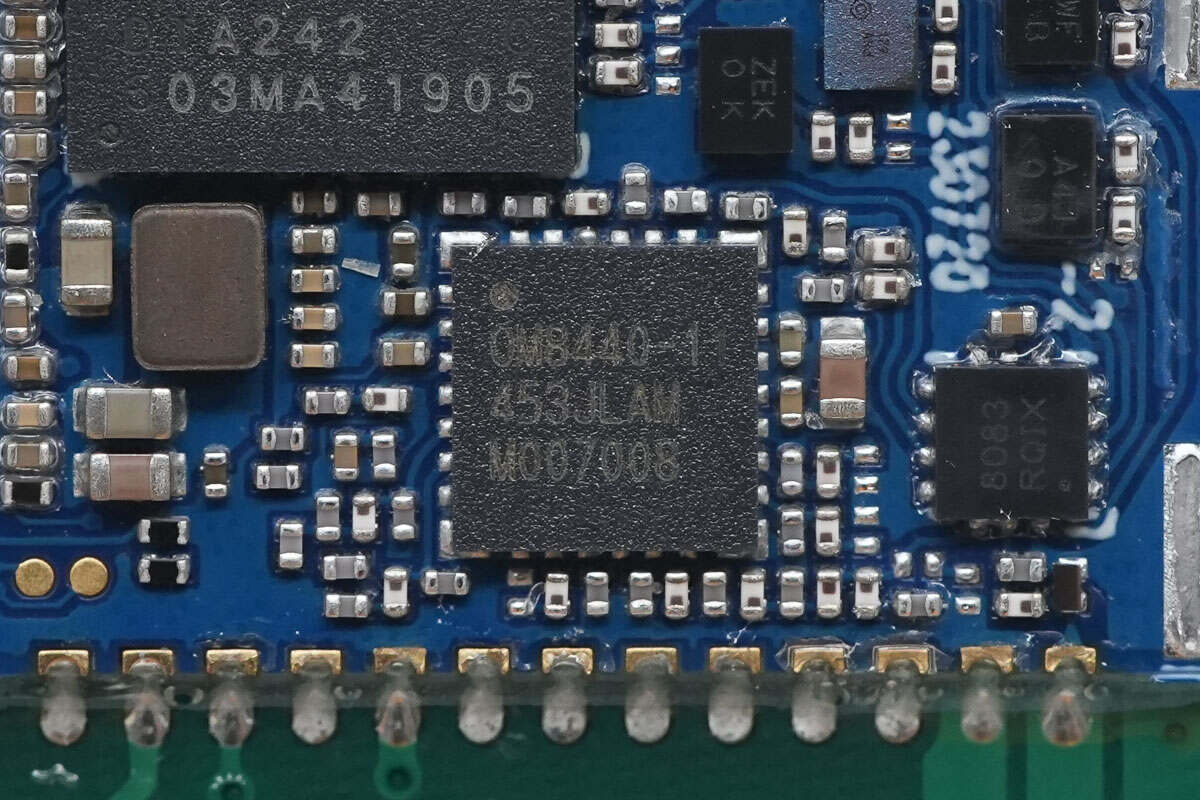
The front-end chip is supplied by OnMicro and is marked with the model number OM8440-1.
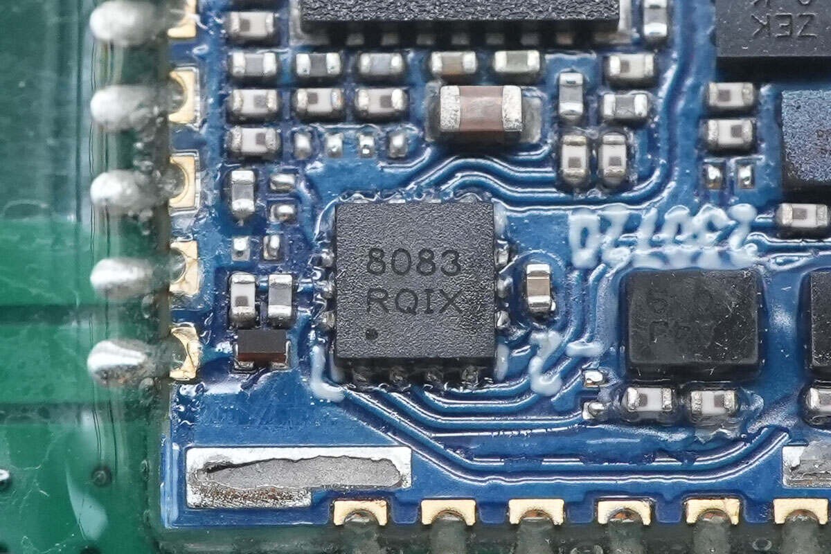
Close-up of the antenna switch marked with 8083.。
The buck converter chip that supplies power to the wireless communication module is the SGM61230 from SGMICRO.
Close-up of the 10μH buck inductor.
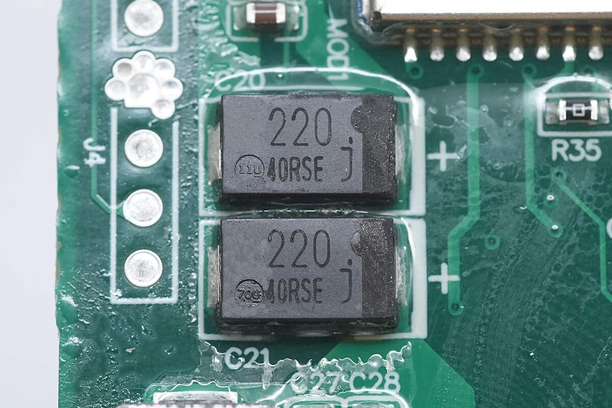
The specifications of the two filter capacitors are 220μF 6.3V.
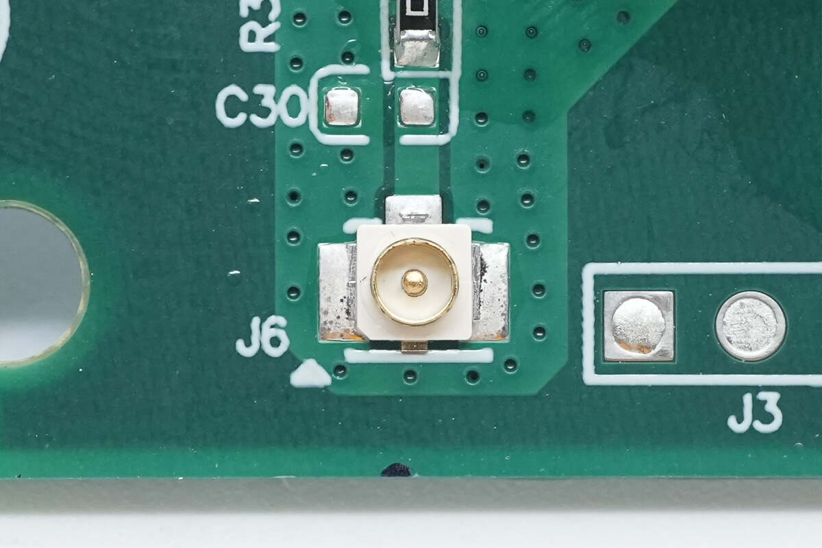
Close-up of the antenna socket.
Close-up of the SMD LEDs used to indicate module operation.
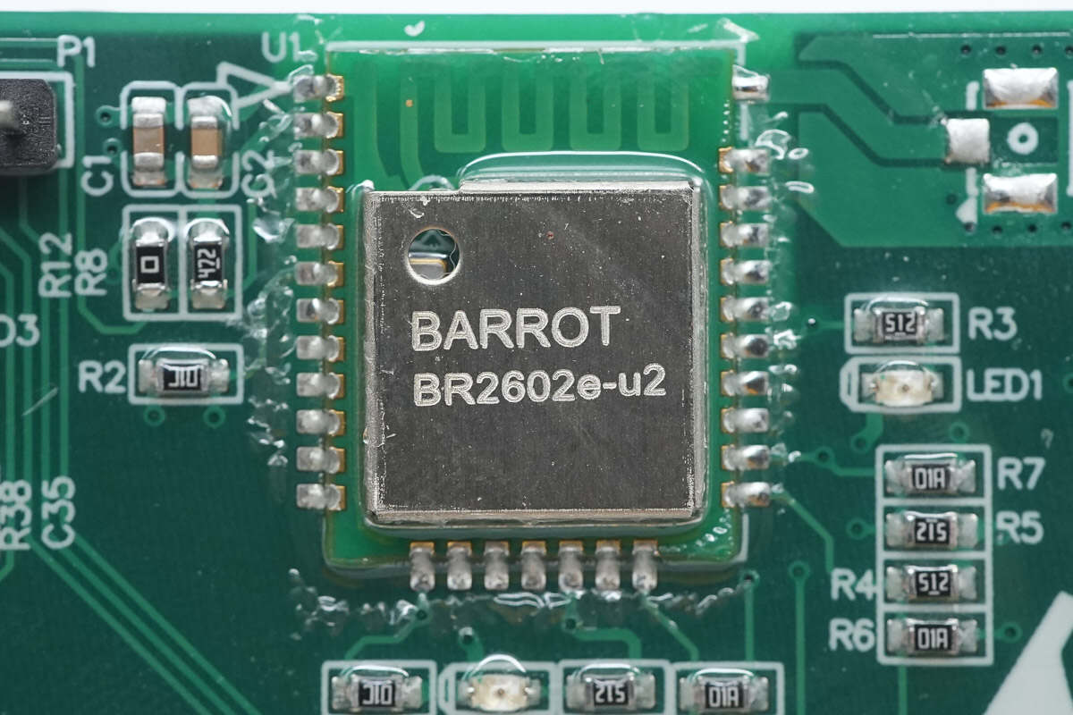
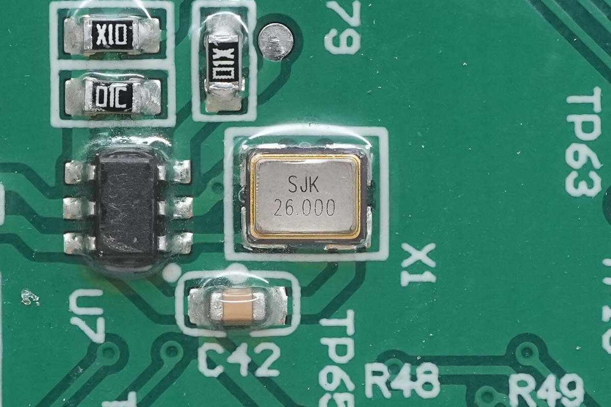
The Bluetooth communication module is from BARROT, model BR2602e-u2, supporting Bluetooth V5.1 single mode, and is used for smartphone connection and control.
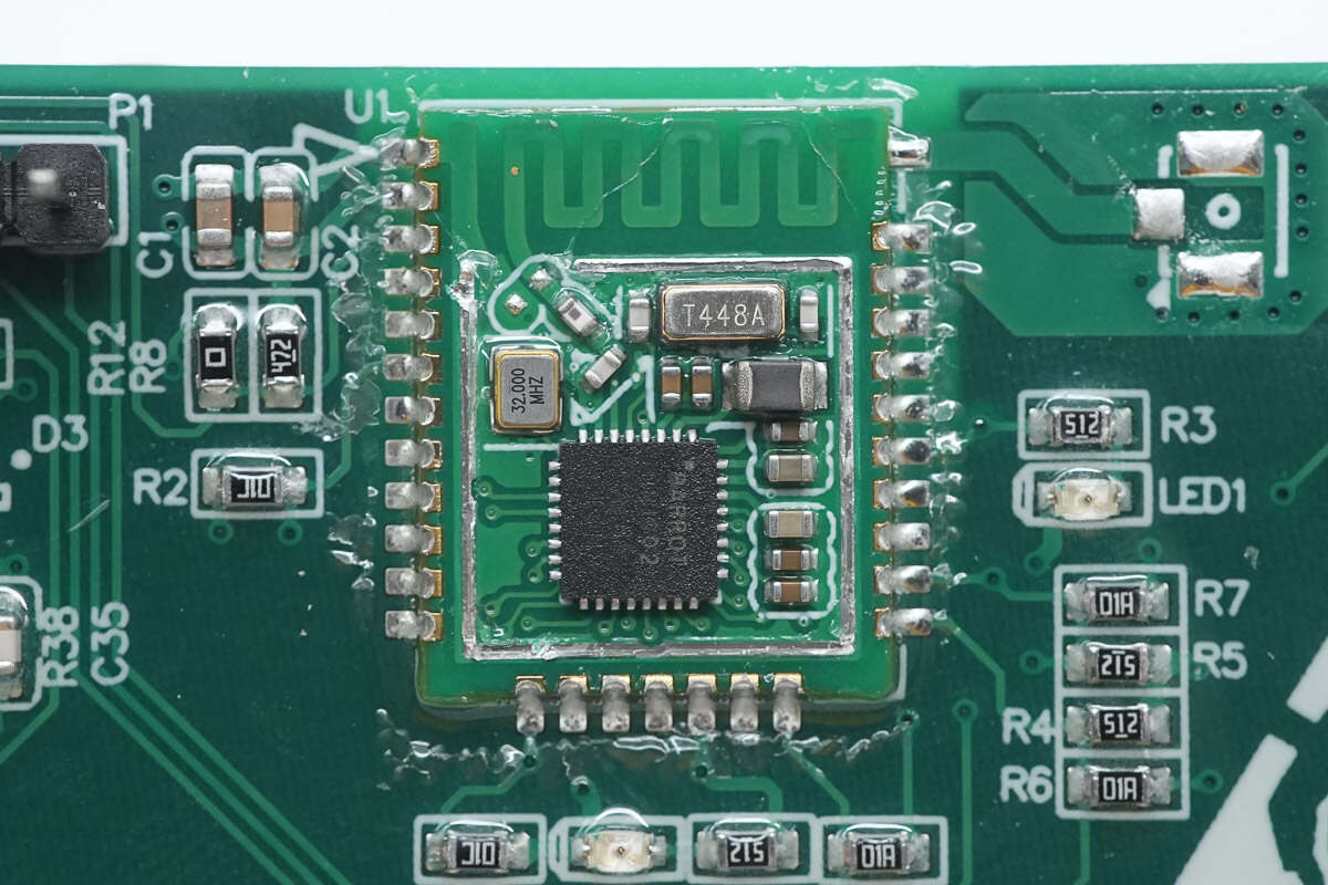
The module has a built-in master control chip and a crystal oscillator.
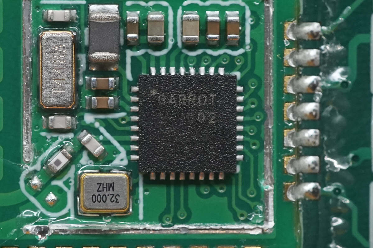
The master control chip is the BR1002 from BARROT, integrating a 32-bit RISC MCU, Bluetooth baseband, and RF transceiver, packaged in a QFN32 form factor.
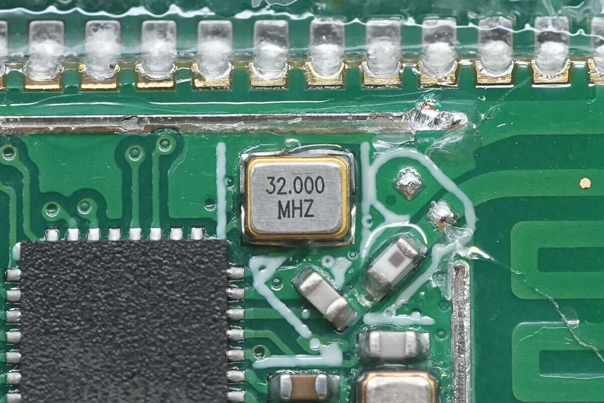
Close-up of the 32.000MHz clock crystal oscillator.
Close-up of the 32.768KHz clock crystal.
On the back side, there are RGB LEDs and an eSIM card chip.
The RGB LEDs are used to indicate power status and charging status.
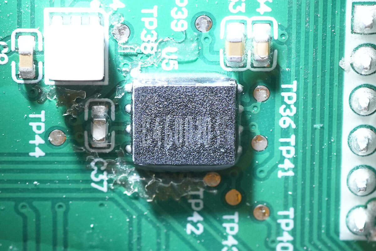
The eSIM card chip is marked with B4600103.
The RF communication chip is from HOPERF, marked with "9A," model CMT2119A. It is an FSK/OOK transmitter chip packaged in SOT23-6.
Close-up of the chip's external 26.000MHz clock crystal oscillator.
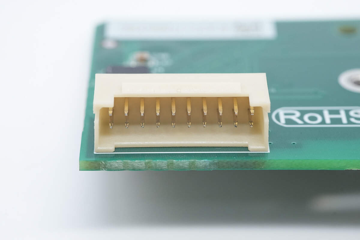
Close-up of the flat flexible cable connector connecting to the bottom PCBA module.
Close-up of the flat flexible cable connector for the screen.
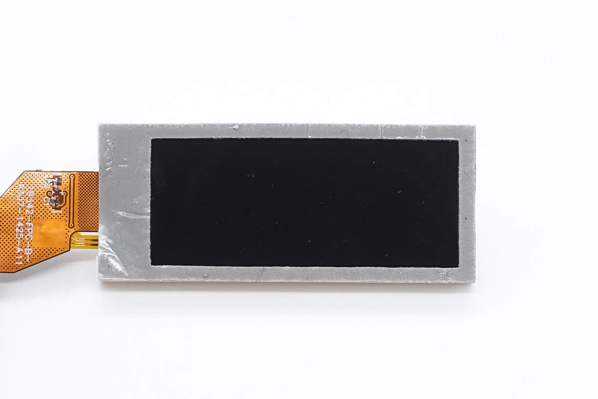
The screen is sealed with adhesive foam tape for dust protection.
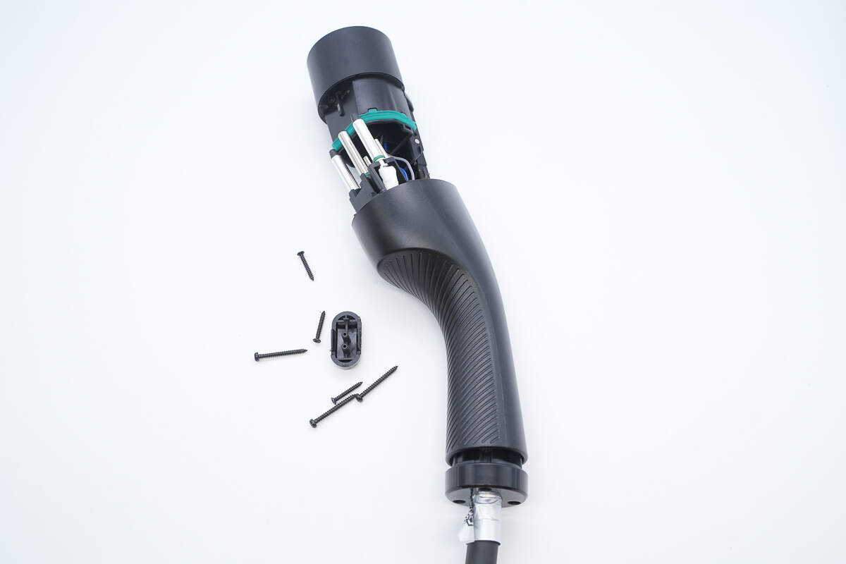
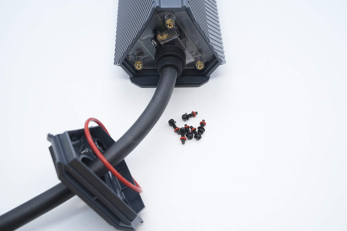
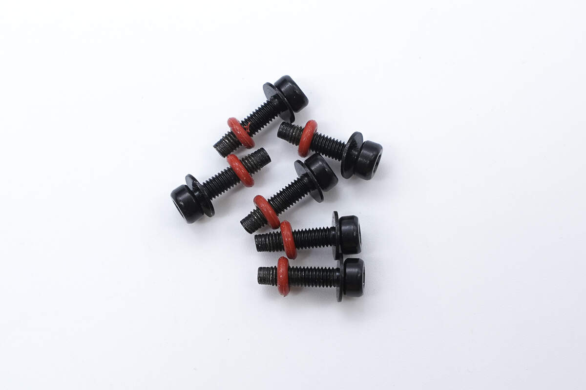
To disassemble the charging connector, first remove the screws, then separate the plug housing from the handle assembly.
A green rubber sealing ring is positioned between the plug housing and the handle to ensure proper sealing.
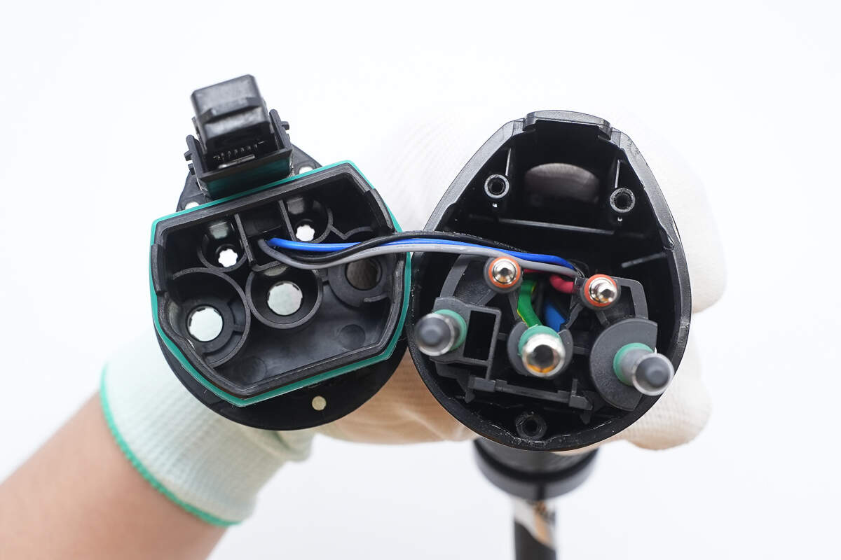
Inside the locking mechanism, there is a switch used to detect whether the connector is properly inserted. It is connected via wiring.
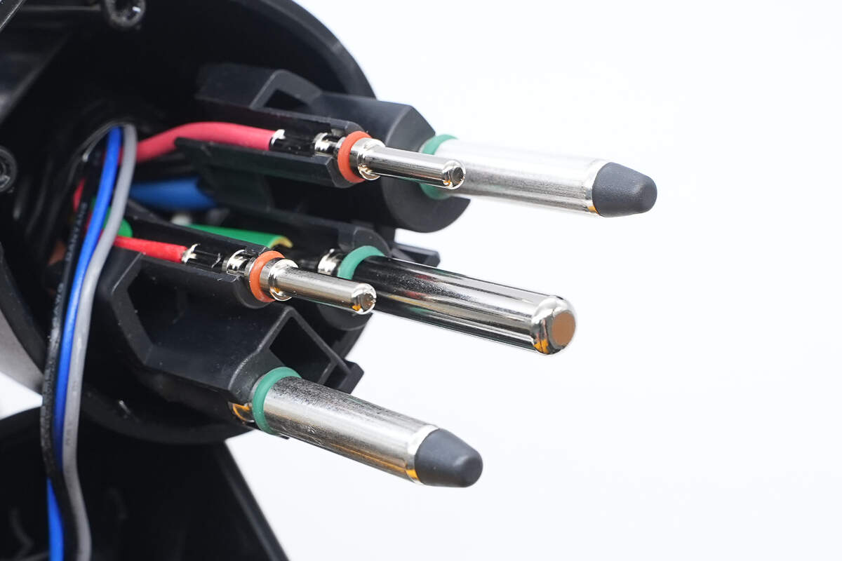
The connector pins are equipped with sealing rings to prevent moisture ingress.
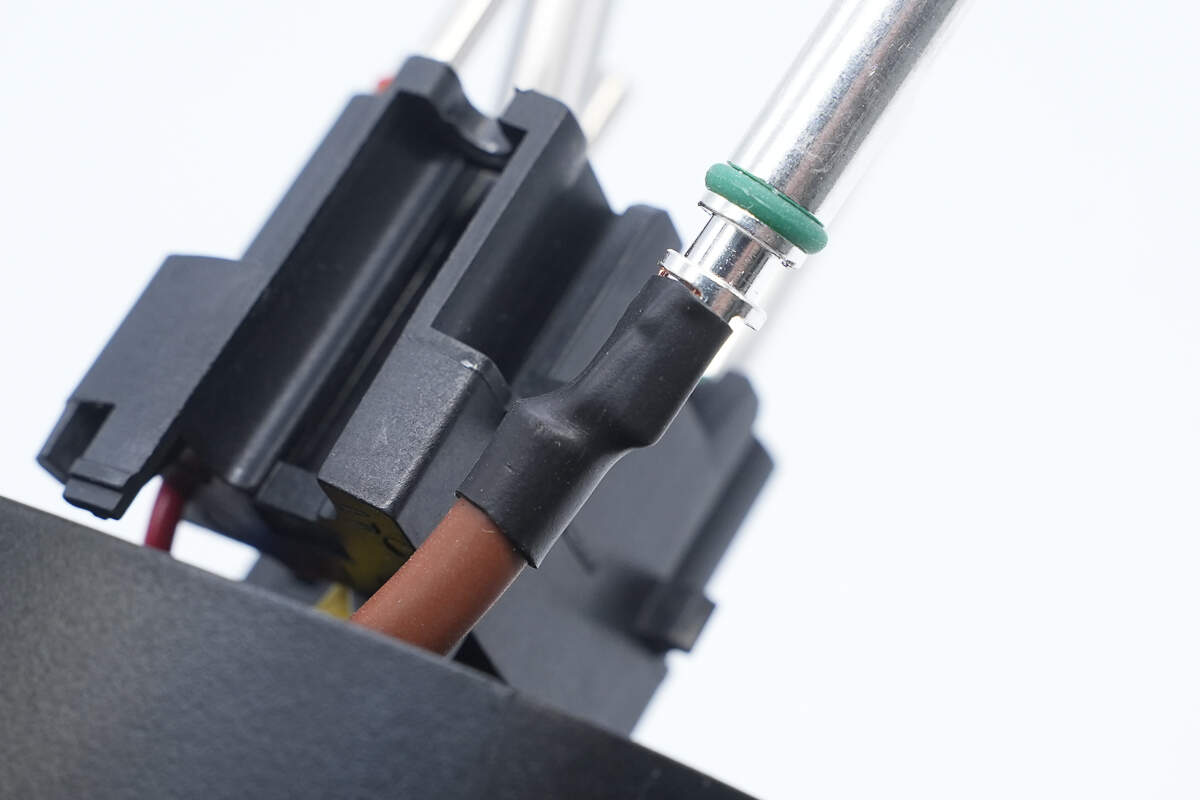
The solder joints of the connector pins are protected with heat shrink tubing.
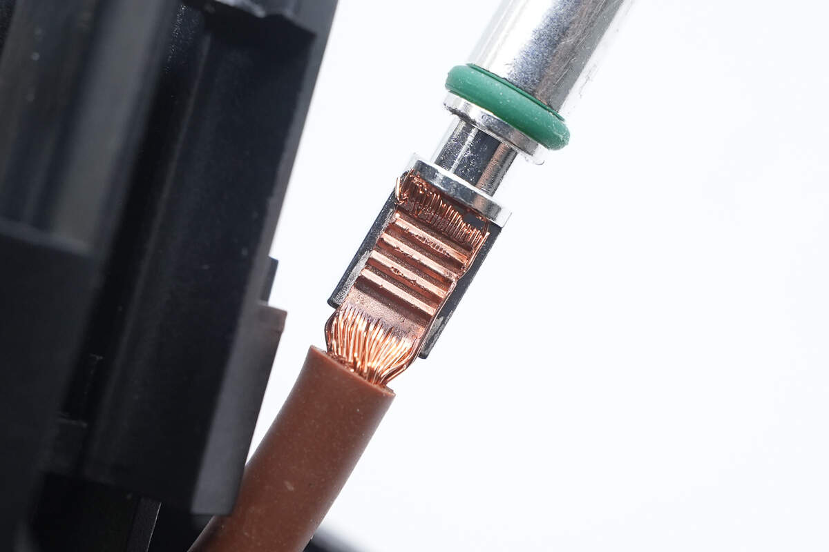
The connector pins utilize ultrasonic welding, which results in lower temperature rise, reduced oxidation, and enhanced safety.
Well, those are all components of the StarCharge 7kW Smart AC Charger.
Summary of ChargerLAB
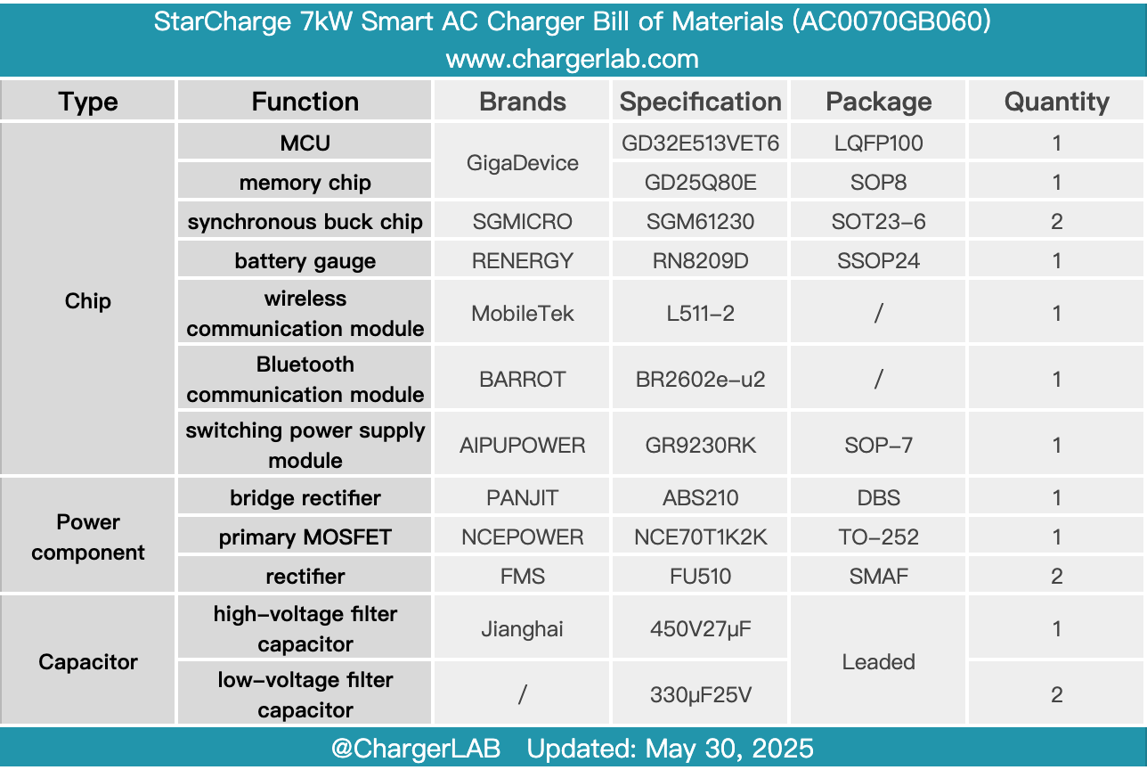
Here is the component list of the StarCharge 7kW Smart AC Charger for your convenience.
It supports a charging power of 220V/7kW and offers lifetime free 4G data connectivity. The device enables remote control via a mobile app. Featuring industry-leading IP67 protection, it provides excellent dustproof and waterproof performance, making it reliable for outdoor use. The charging station utilizes terminal tinning technology, which reduces heat generation and enhances mechanical stability. The charging gun plug employs ultrasonic welding technology, resulting in lower heat generation and improved safety.
After taking it apart, we found that it consists of two PCBA modules. The overall control is managed by a GigaDevice GD32E513VET6 MCU, while voltage and current parameters are acquired using the RENERGY RN8209D. The MobileTek L511-2 wireless communication module enables mobile app control, and the BARROT BR2602e-u2 Bluetooth module supports Bluetooth connectivity.
The PCBA modules are secured within a plastic frame and coated with conformal coating for protection. Silicone sealing rings are applied to both the screws and the enclosure to enhance waterproofing. Wire connection terminals are tinned after crimping to fill any gaps and reduce contact resistance. As promoted by StarCharge, the charger features triple temperature protection mechanisms: ambient temperature protection within the station, relay temperature protection, and connector-end temperature protection. Combined with robust construction and high-quality materials, it offers comprehensive safety and reliability for your vehicle.
Through this detailed teardown, the product's high standards in manufacturing processes and component selection are evident, aligning well with the manufacturer's claims of superior protection and safety performance. As a platform committed to identifying outstanding technology products, ChargerLAB will continue to track and explore high-quality offerings that stand out through genuine technical excellence. With our professional perspective, we aim to help users identify true value in the world of tech-enabled living.
Related Articles:
1. Teardown of UGREEN Thunderbolt 5 80Gbps M.2 NVMe SSD Enclosure (D705)
2. Teardown of OPPO 10000mAh 22.5W Energy Jelly Power Bank (PBSV00)
3. Teardown of UGREEN Nexode Car Charger 90W with Retractable USB‑C Cable (EC603)