Introduction
We have received the MEGMEET MSP600 switching power supply. It features a hot-swappable design and supports a wide input voltage range of 100–240V AC. The module provides a rated output of 12V at 48A, along with a standby output of 5V at 4A.
The input side includes a cooling fan, an AC input socket, and status indicators. The output side is equipped with a gold finger connector. Internally, the power supply adopts a PFC + active clamp forward converter topology with self-driven synchronous rectification. Below is the teardown to explore its internal design and component quality.
Product Appearance

The module uses an aluminum alloy enclosure secured with screws. A label is affixed to the front panel.

Model: MSP600
Input: 100–240V~, 50/60Hz, 9A Max
Output: +5VSB 4A, +12V 48A
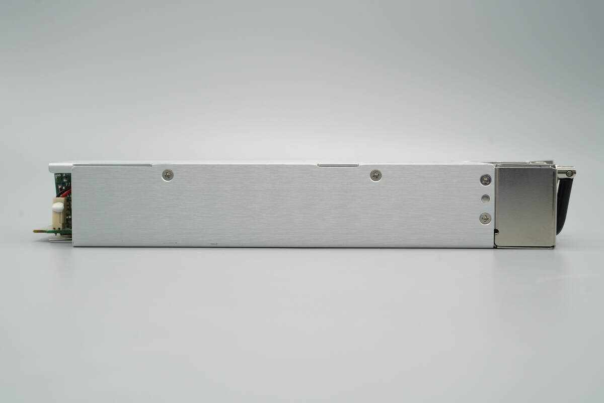
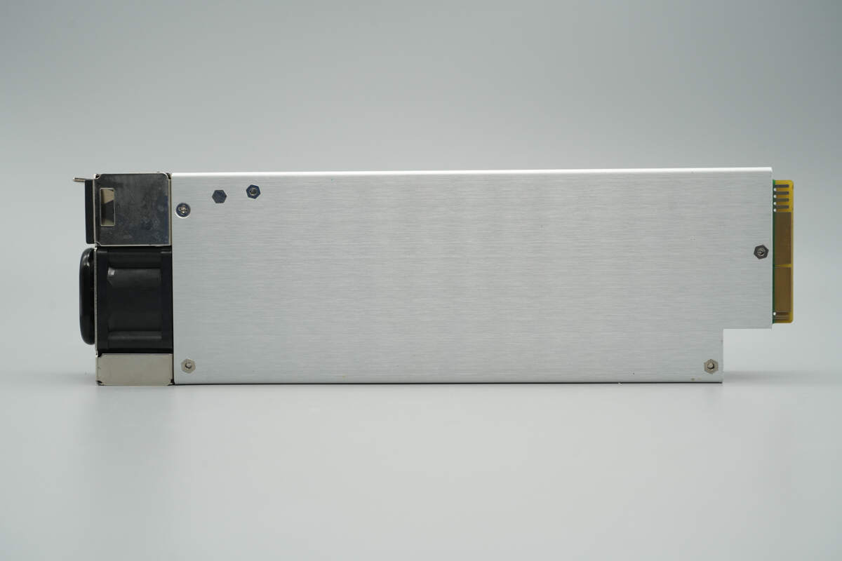
This side is secured with screws.
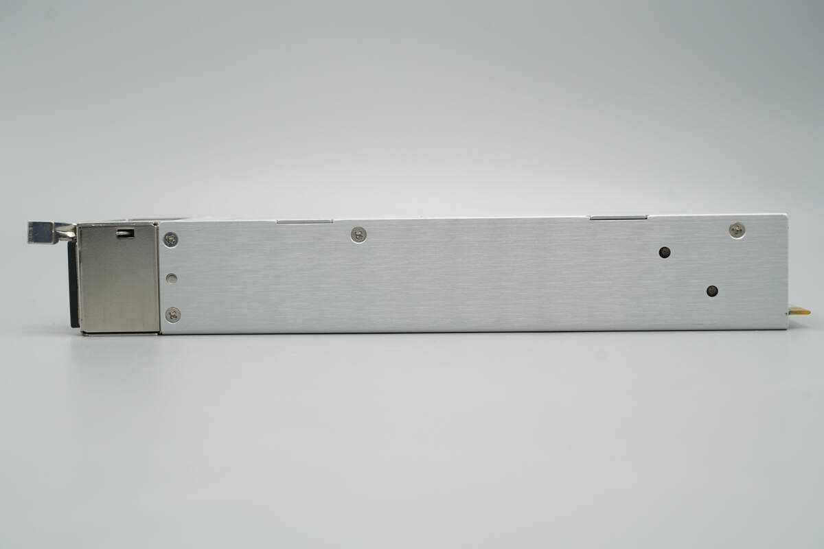
The opposite side is also secured with screws.
The back features mounting screw posts.
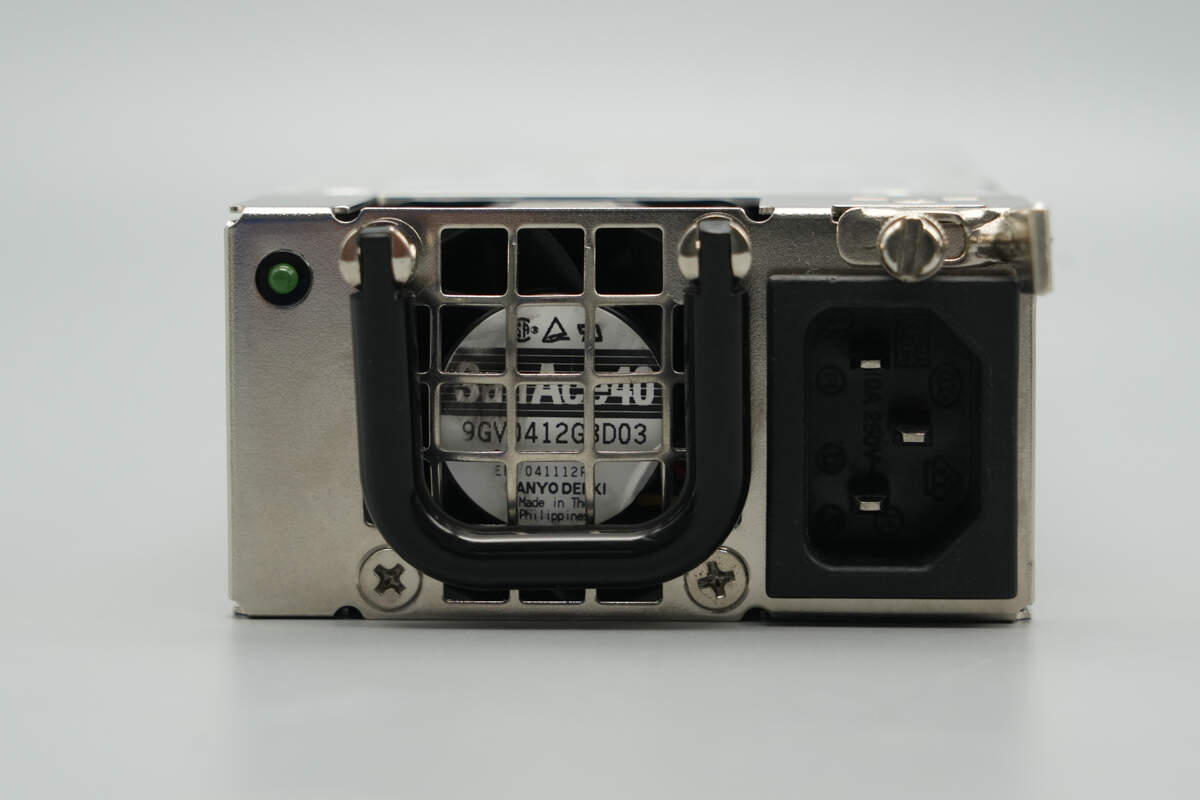
The input side is equipped with a handle, a cooling fan, an input socket, a power indicator light, and a release latch.
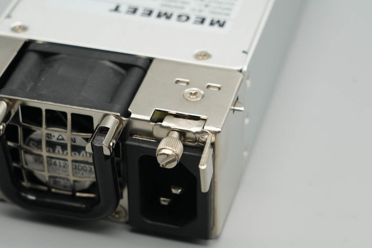
The release latch is secured with screws.
The output side features an open design, allowing visibility of the internal components.
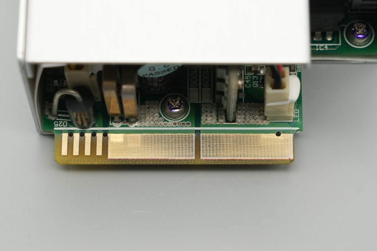
Close-up of the gold finger PCB.
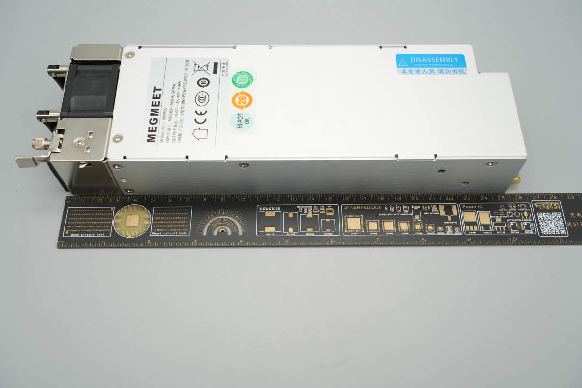
The length of the module is about 262 mm (10.31 inches).

The width is about 79 mm (3.11 inches).

The thickness is about 40.7 mm (1.6 inches).
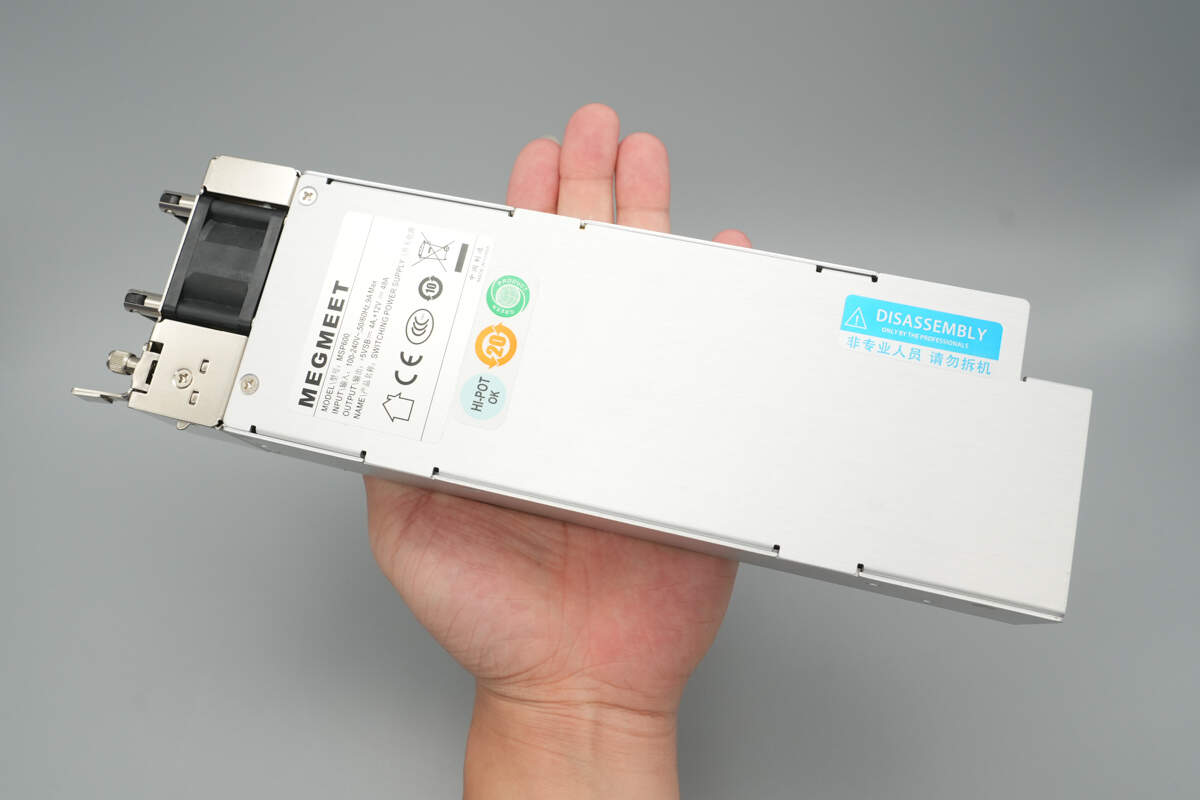
That's how big it is in the hand.

The weight is about 1016 g (35.84 oz).
Teardown
Next, let's take it apart to see its internal components and structure.

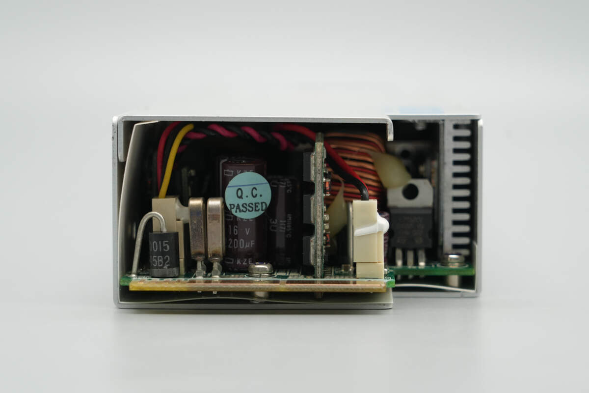
Unscrew the screws and remove the cover.

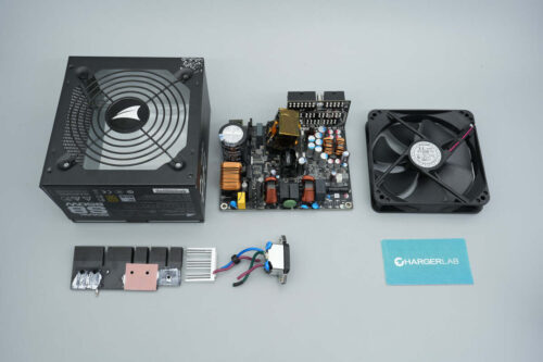
The PCBA module is secured with screws.
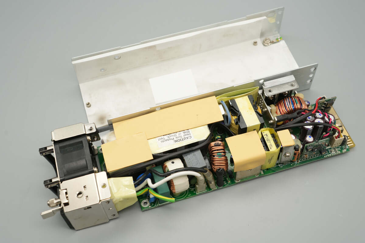
Unscrew the screws and remove the PCBA module. Inside the enclosure, there is a white Mylar sheet.
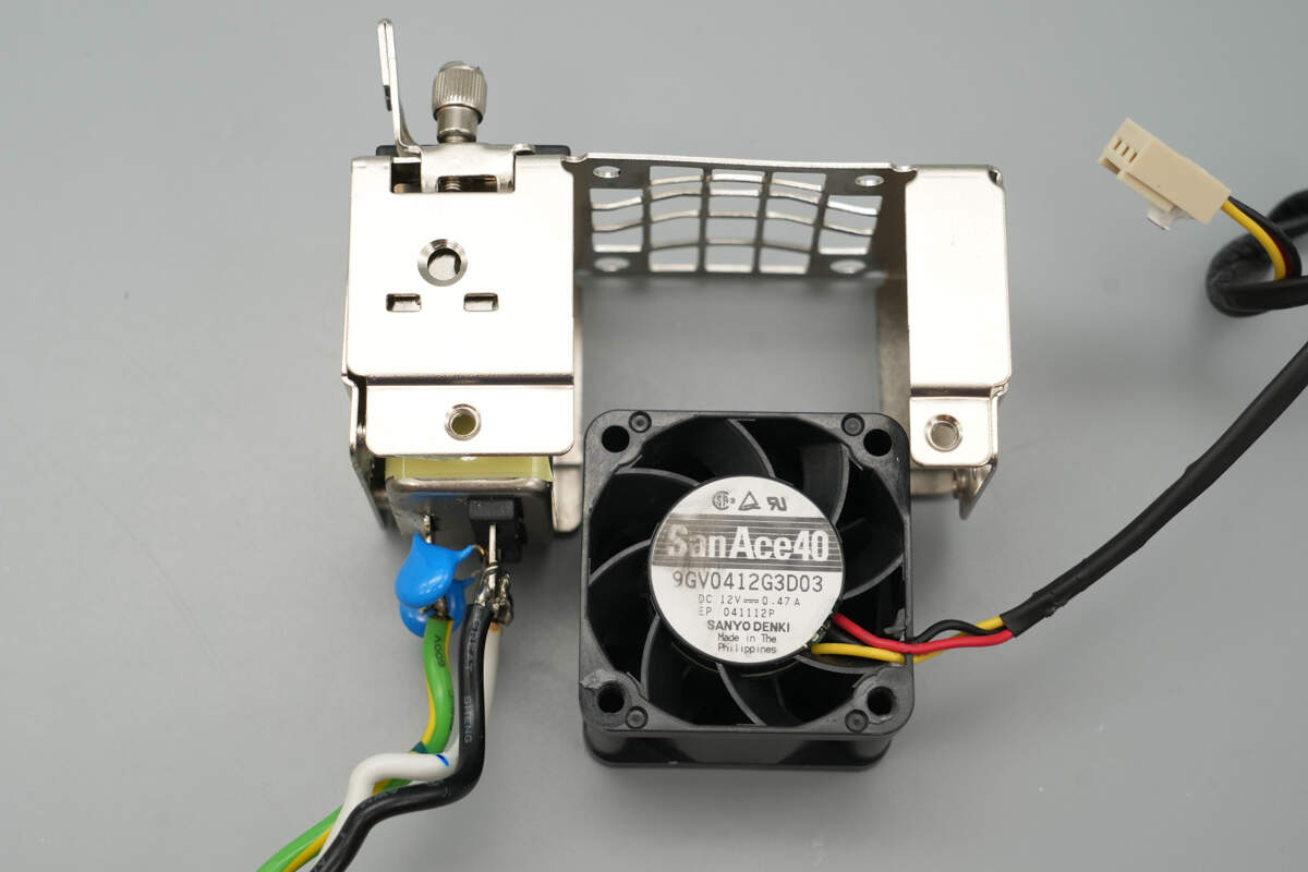
Close-up of the input filter and cooling fan.
The input filter is from High & Low Corp., model 10SS1-LHGR-Q.
The output wires are connected by soldering, and blue Y capacitors are also soldered in place.
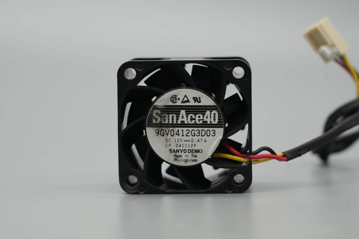
The cooling fan is from SANYO DENKI, model 9GV0412G3D03, rated at 12V 0.47A.

The length of the PCBA module is about 228 mm (8.98 inches).

The width is about 75.8 mm (2.98 inches).
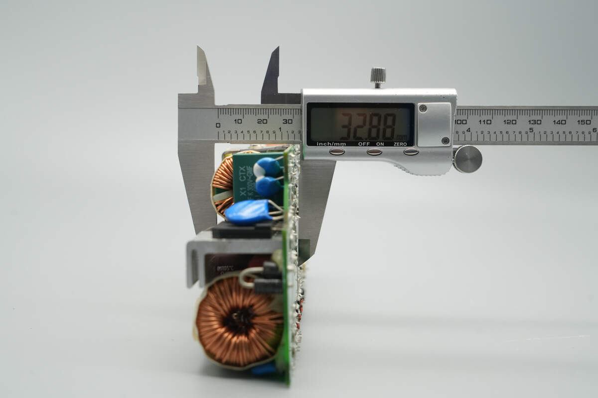
The thickness is about 32.9 mm (1.3 inches).
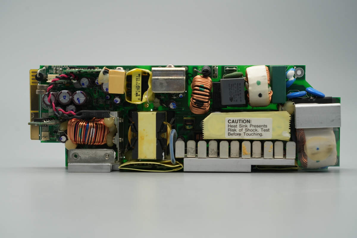
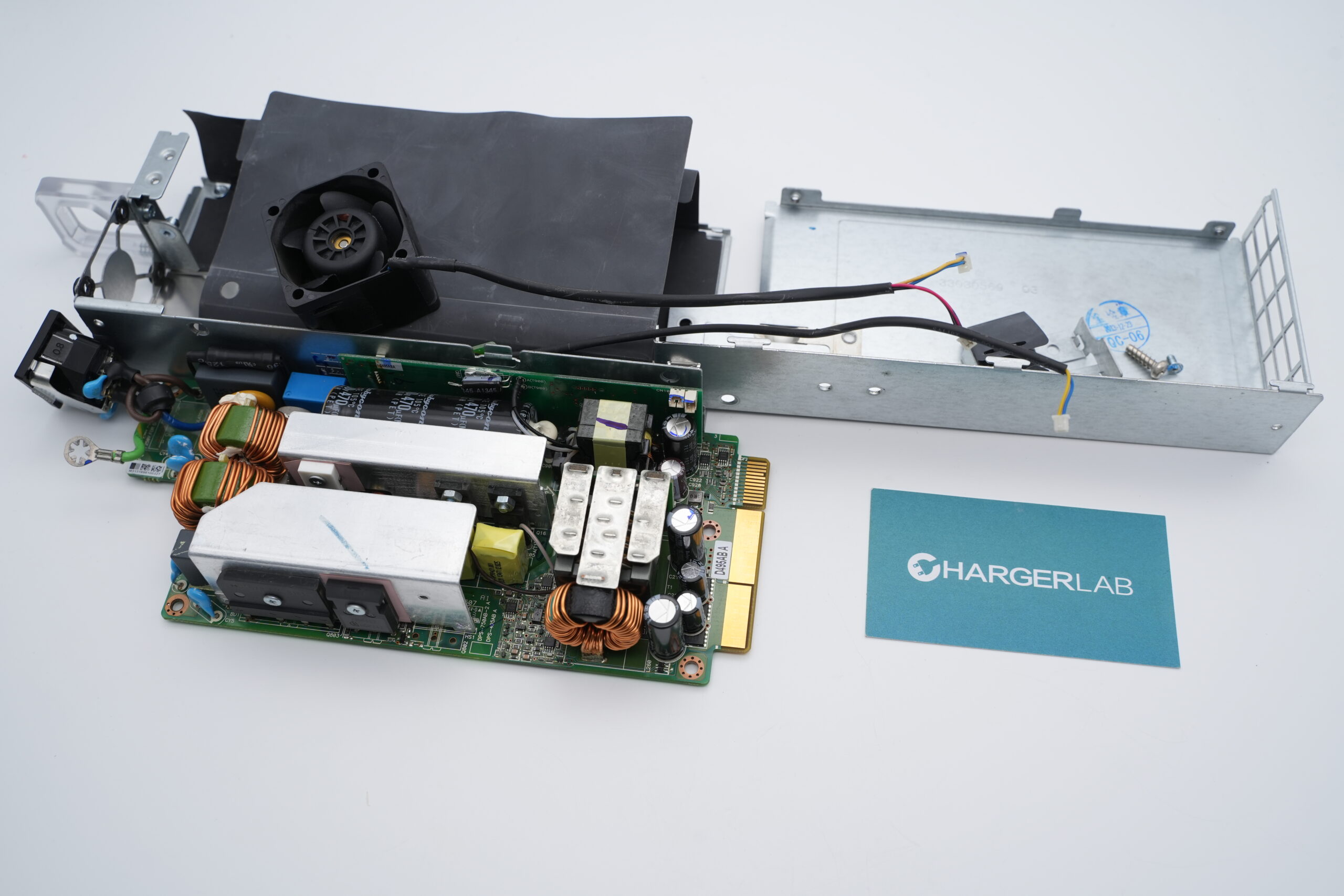
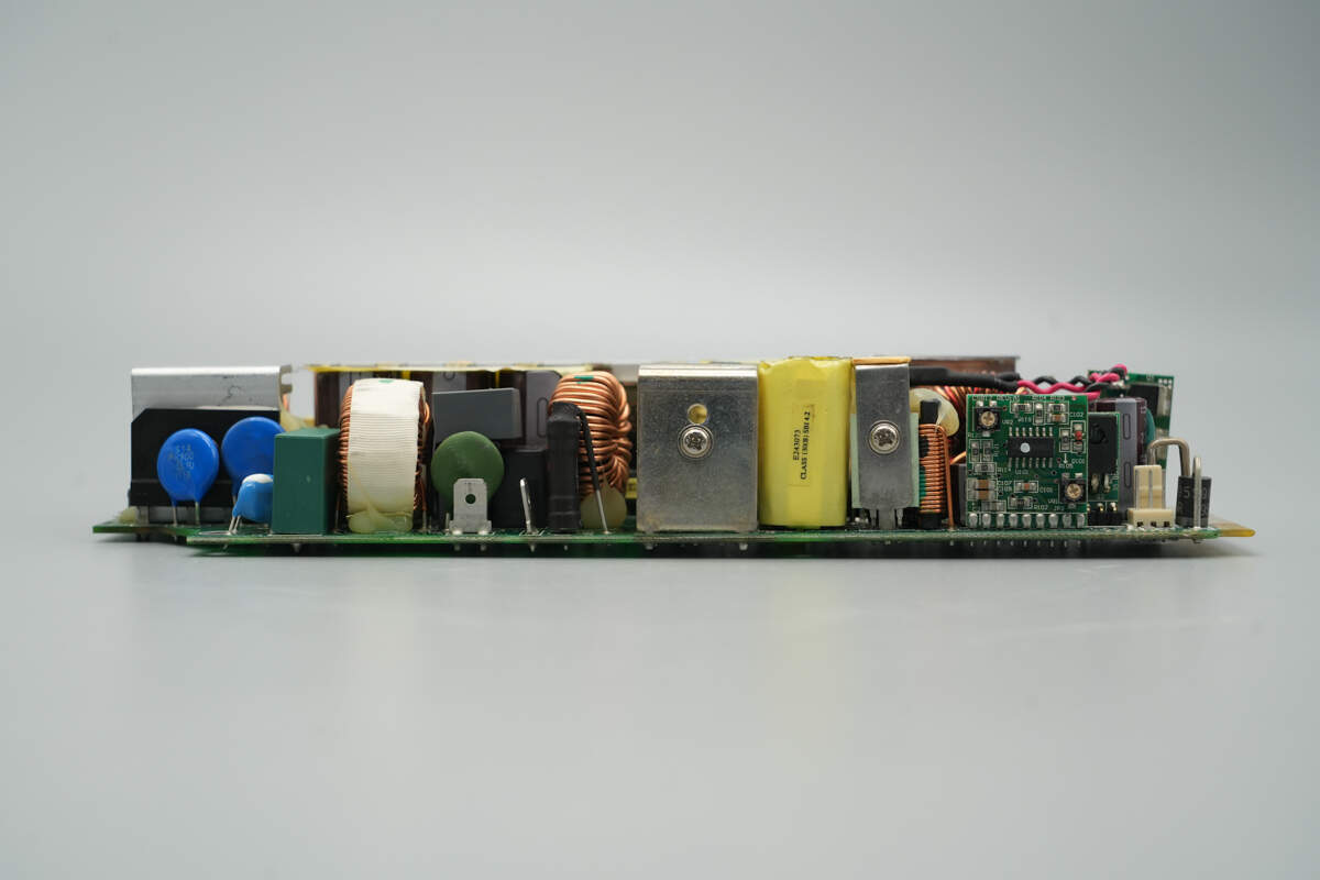
Front view of the PCBA module:
On the upper right side is the AC input section, which includes a fuse, common mode choke, relay, NTC thermistor, safety X2 capacitors, varistors, and Y capacitors. A heatsink is attached to the bridge rectifier, and below it is the PFC boost inductor.
On the left side are the transformer, synchronous rectifiers, filter inductor, filter capacitors, control PCB, standby power transformer, and standby power MOSFET.

The back is equipped with a driver, feedback optocouplers, and a control chip.
On this side, the left section is the input side, featuring a fuse, filter inductor, relay, NTC thermistor, common mode choke, and safety X2 capacitors. The right section includes the standby power MOSFET, standby power transformer, standby power rectifier, and control PCB.

The opposite side features heatsinks, an active clamp forward converter control PCB, and a PFC control PCB.

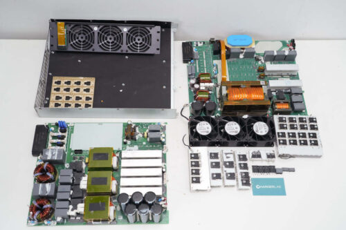
Remove the small PCBs, power components, and other components.
The input fuse is insulated with a heat shrink tube.

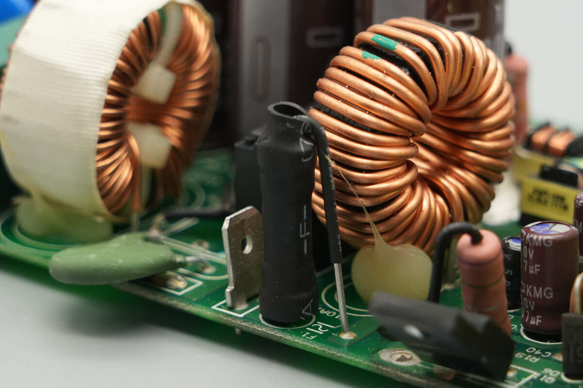
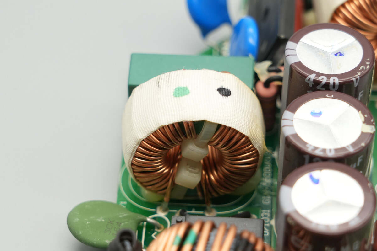
The filter inductor uses a toroidal winding design.

The relay is from SongChuan, model 835NL-1A-B-C. It features a single normally open contact with a contact rating of 8A at 250V, and a coil voltage of 12V.
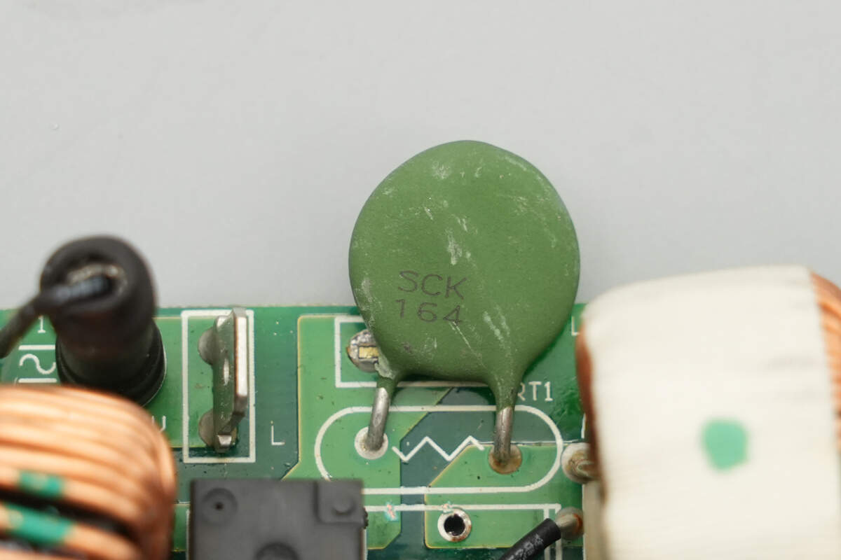
The NTC thermistor is marked with SCK164.
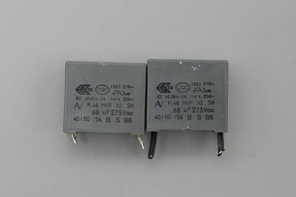
The safety X2 capacitors are rated at 0.68μF.
The common mode choke is wound with enameled wire.
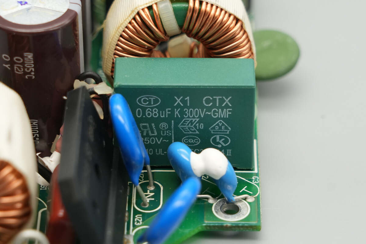
The safety X2 capacitor is rated at 0.68μF.
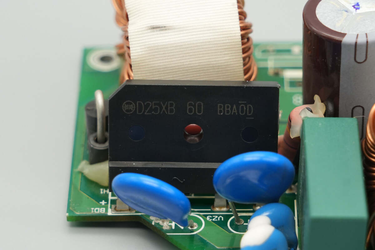
The bridge rectifier is from Shindengen, model D25XB60, rated at 25A 600V, and uses a 5S package.
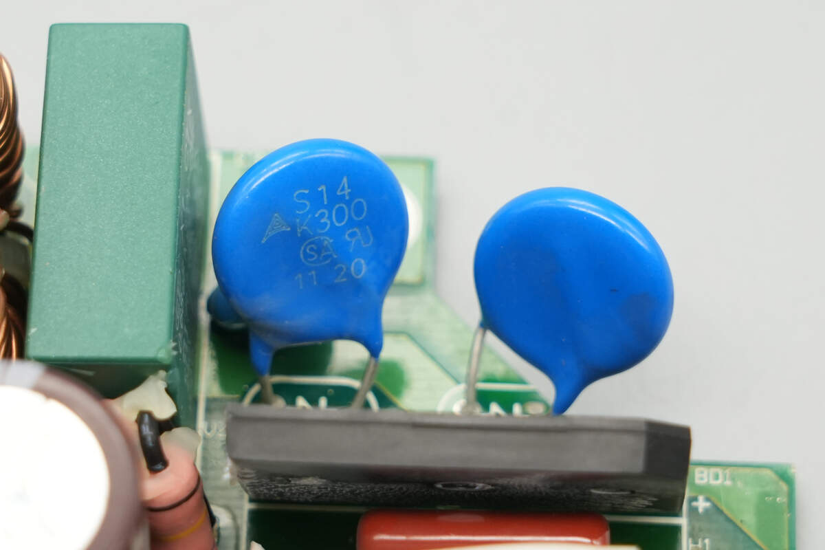
The varistors are from TDK, marked with S14K300.

Close-up of the two blue Y capacitors.
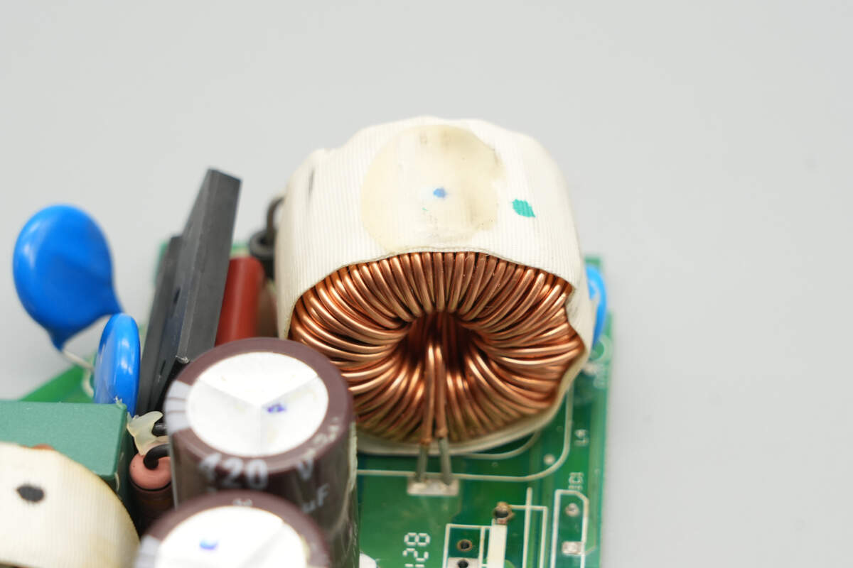
The PFC boost inductor is wound with enameled wire.
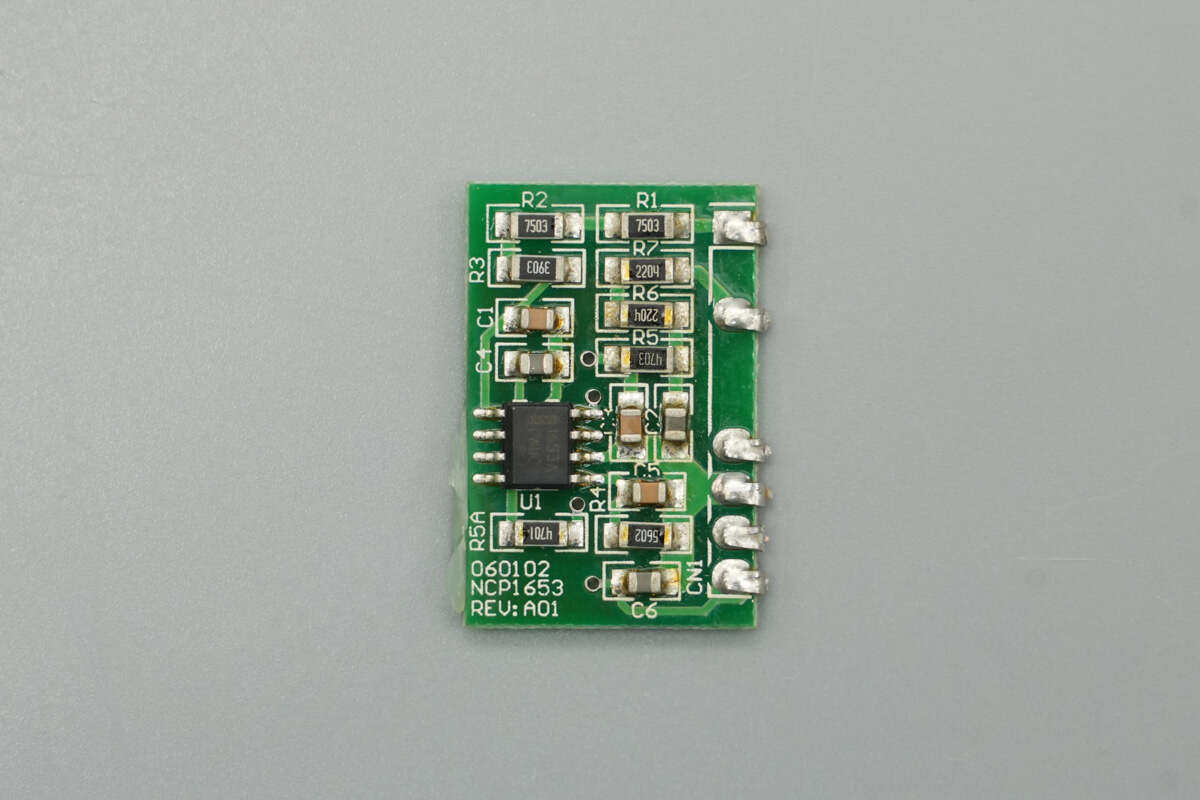
The PFC controller is soldered onto a vertical PCB.
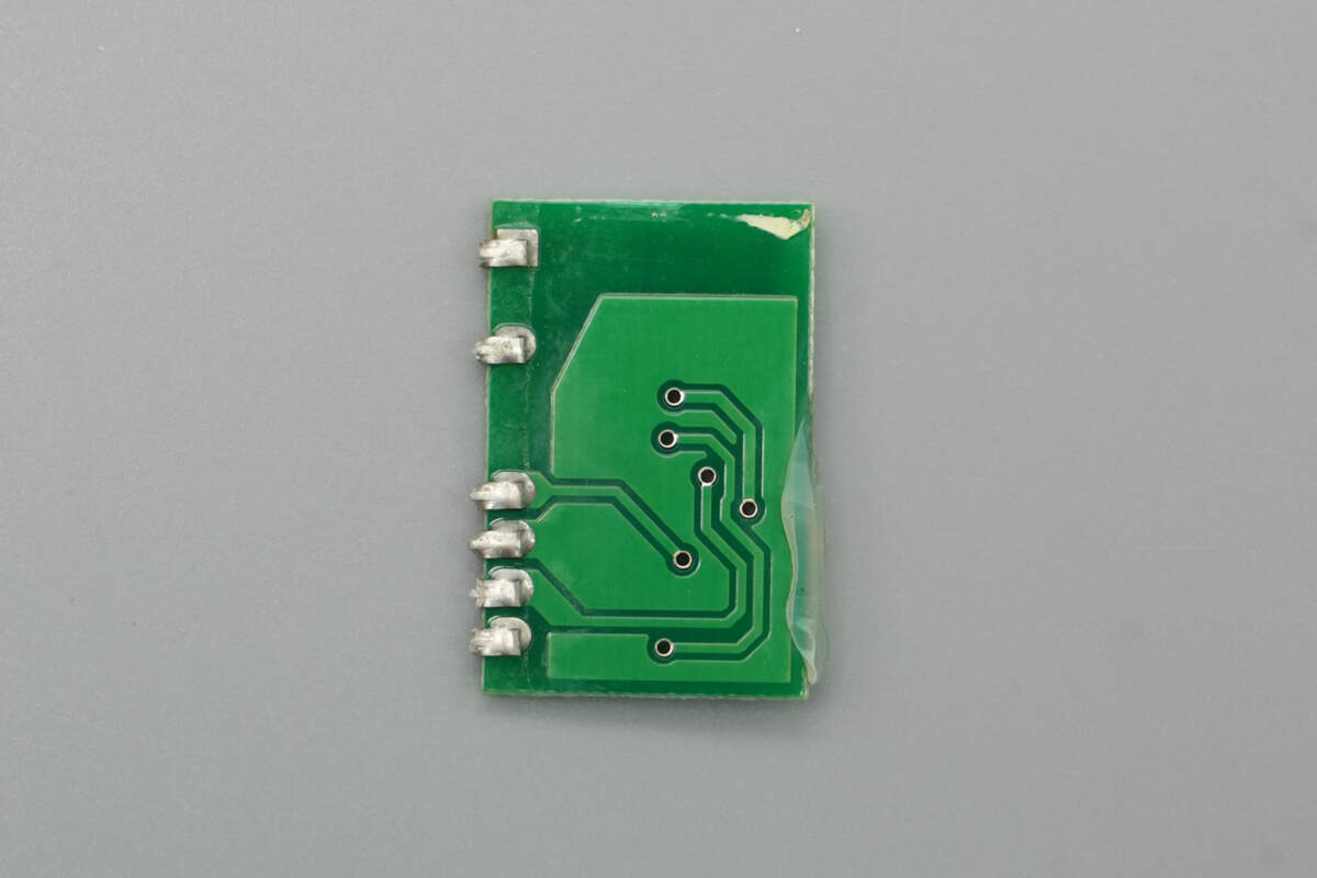
There are no components on the back side.

The PFC controller is from Onsemi, model NCP1653A. It operates in CCM mode with a fixed switching frequency of 67kHz and supports both average current mode and peak current mode operation. The chip features undervoltage lockout, output overvoltage and undervoltage protection, programmable overcurrent protection, and output power limiting. It comes in an SO-8 package.

The filtering capacitor used to power the PFC controller is supplied by CapXon, with a specification of 22μF 25V.

The heatsink houses the PFC MOSFETs, a PFC rectifier, a clamp MOSFET, and a forward converter MOSFET.
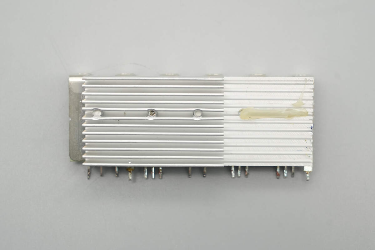
No components are mounted on the back side of the heatsink.
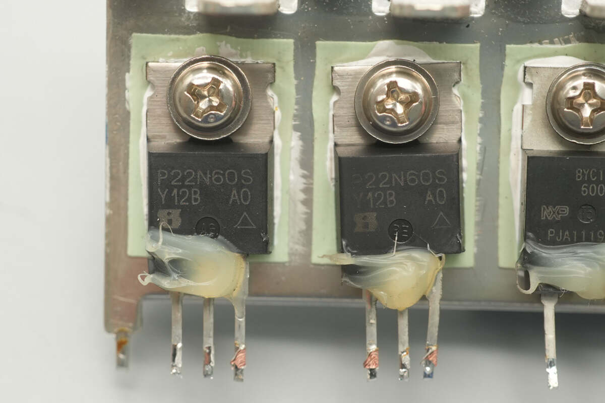
The PFC MOSFETs are sourced from VISHAY, model SIHP22N60S, NMOS type, with a voltage rating of 650V and an on-resistance of 190mΩ, housed in a TO-220AB package.
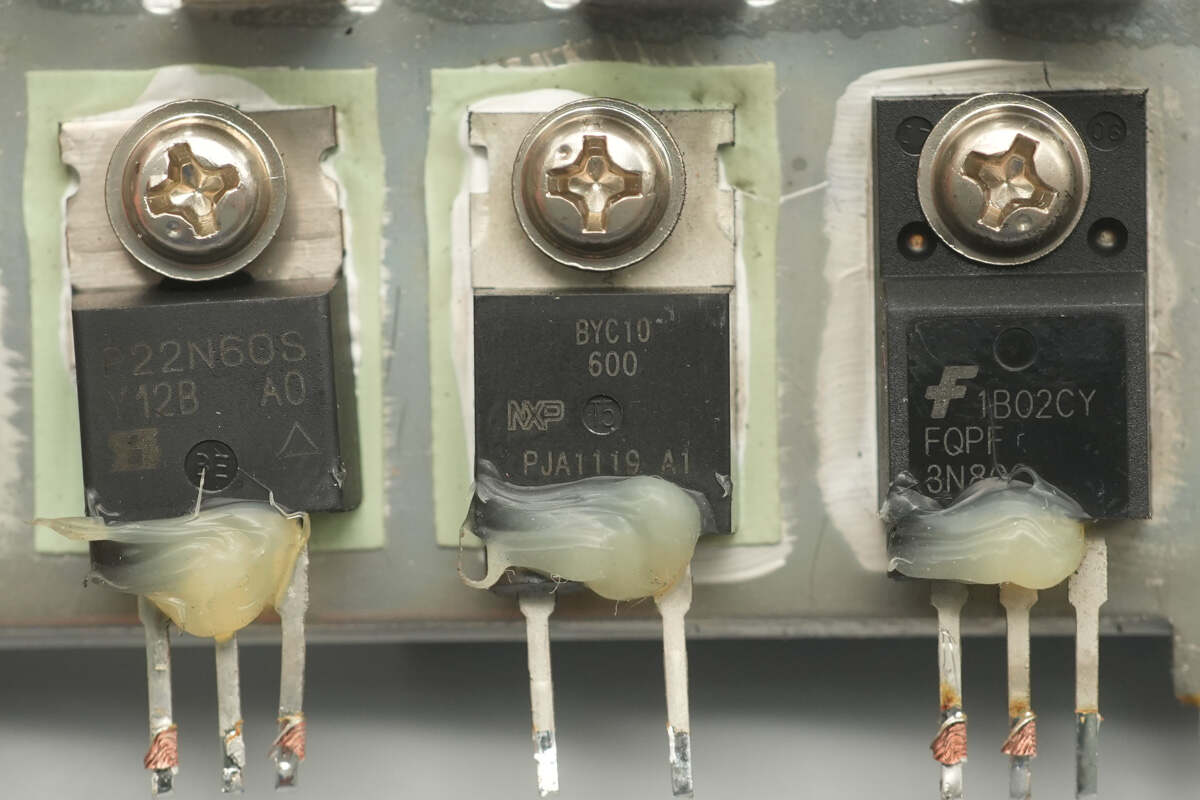
The PFC rectifier is sourced from RePower, model BYC10-600, an ultra-fast recovery diode rated at 600V and 10A, housed in a TO-220AC package.

Three high-voltage filter capacitors are connected in parallel.

The capacitors are sourced from NCC, KMG series, with a rating of 420V 120μF.

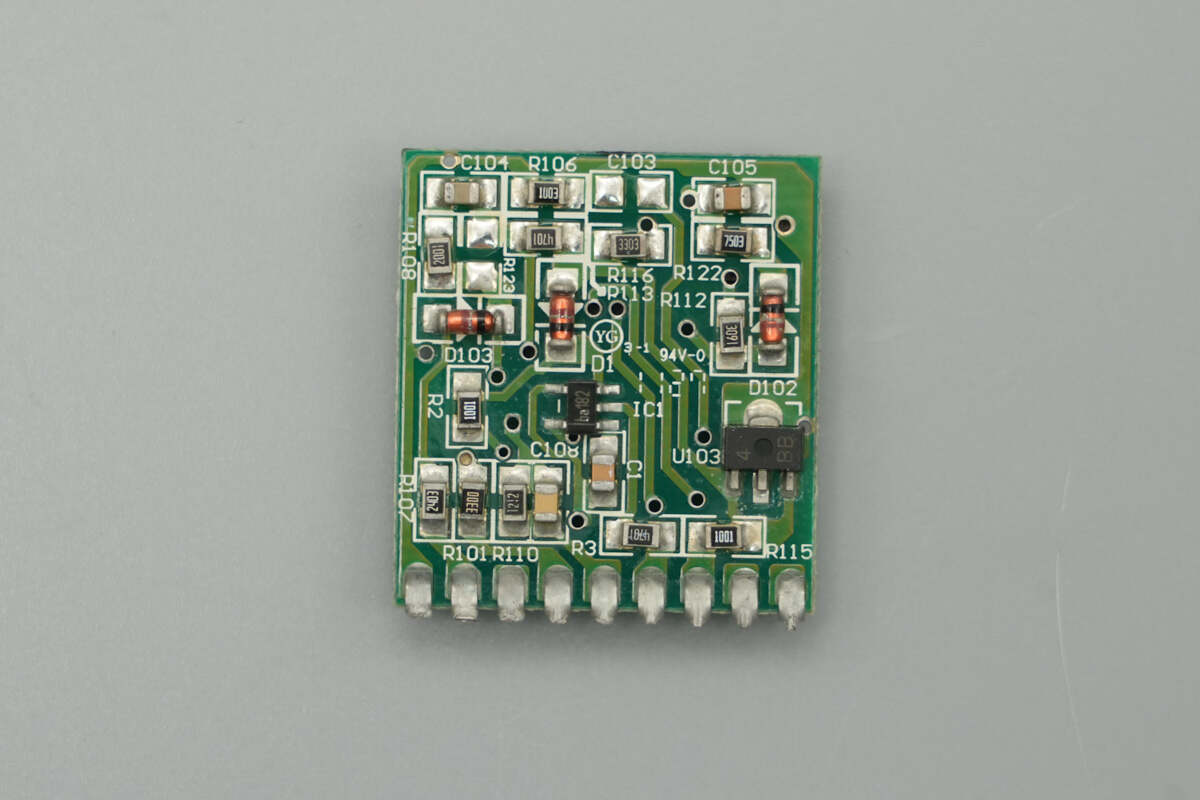
The front side of the control PCB houses the controller and operational amplifier.

The back side contains transistors and voltage regulator diodes.
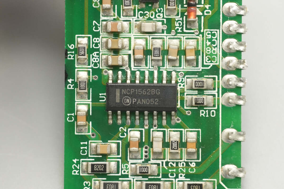
The active clamp forward controller is sourced from Onsemi, model NCP1562B. It features two control outputs and an adjustable delay. The chip includes cycle-by-cycle current limiting, supports switching frequencies up to 1 MHz, and is housed in an SO-16 package.

The voltage comparator is sourced from STMicro, model LM393, a low-power dual voltage comparator housed in an SO-8 package.

A current transformer is used to detect the MOSFET current.

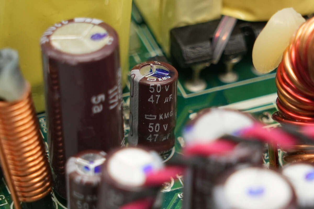
The filtering capacitor for powering the master control chip is rated at 50V 47μF.
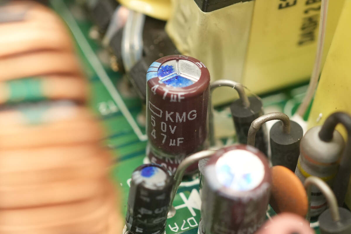
The other filtering capacitor has the same specifications.
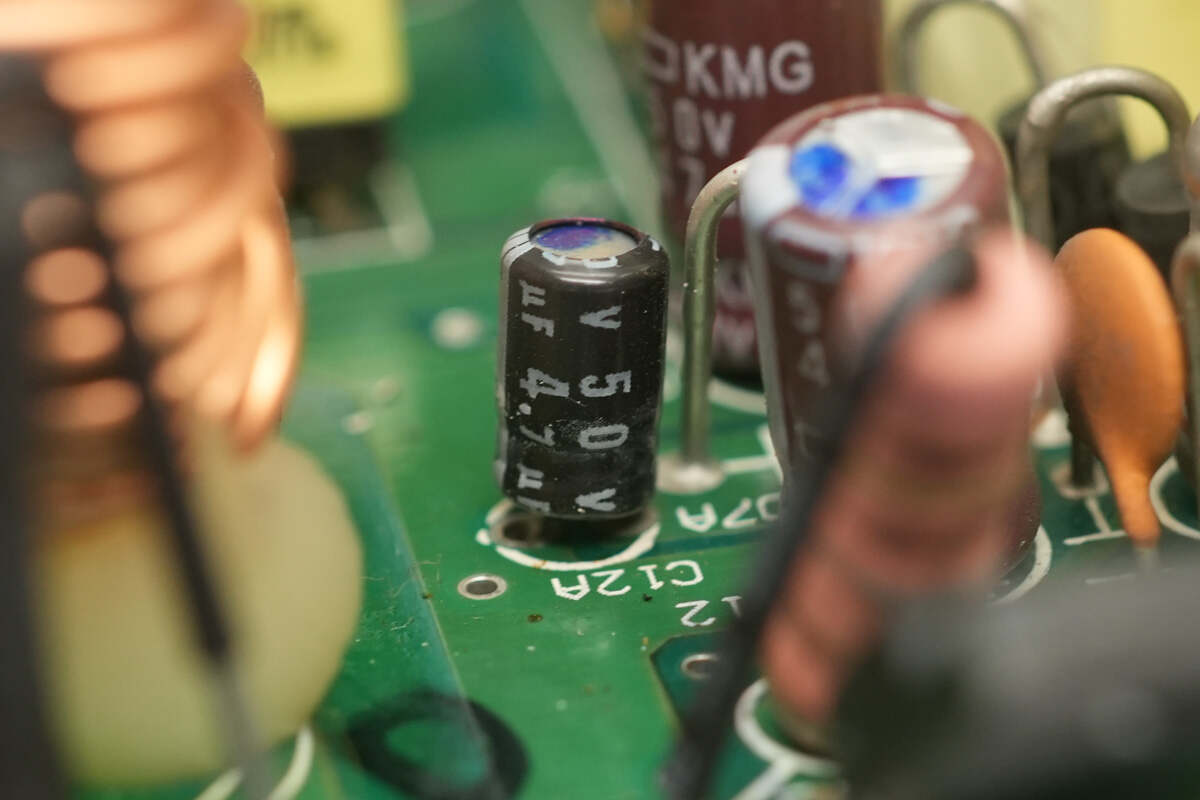
This filtering capacitor is rated at 50V 4.7μF.

The driver is sourced from Onsemi, model MC34152, a dual high-speed driver featuring two independent channels, 1.5A totem-pole output, undervoltage lockout protection, and housed in an SOIC-8 package.

Close-up of the isolation transformer used for driving the clamp MOSFET.
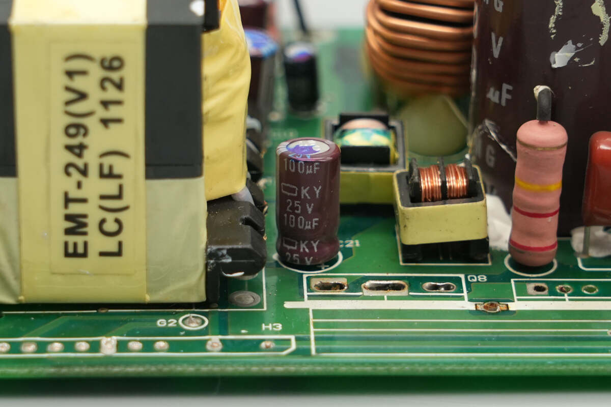
This filtering capacitor is rated at 25V 100μF.
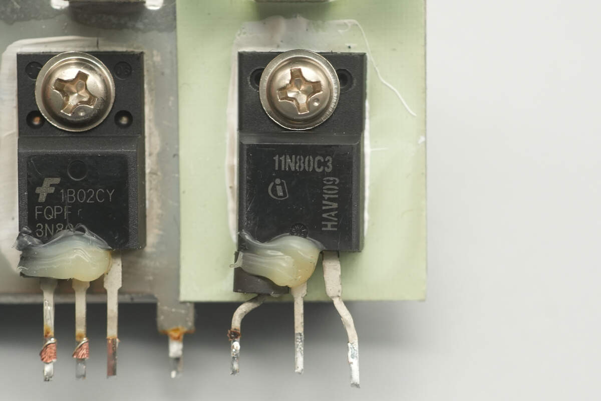
This MOSFET is sourced from Infineon, marked as 11N80C3, model SPA11N80C3. It is an NMOS with an 800V voltage rating and 450mΩ on-resistance, housed in a TO-220-3 package.

The clamp MOSFET is sourced from Onsemi, model FQPF3N80C. It is an NMOS with an 800V voltage rating and 4.8Ω on-resistance, housed in a TO-220FP package.
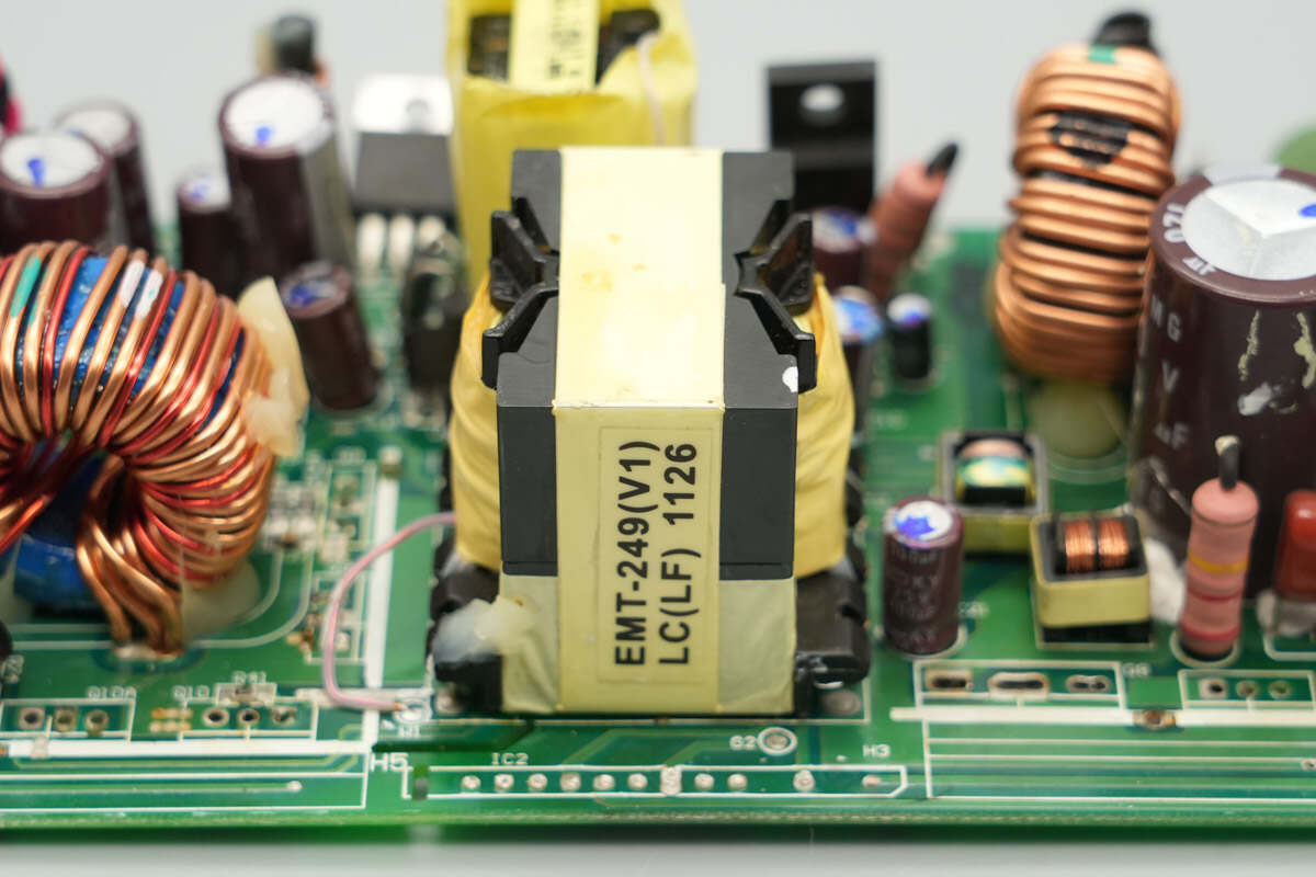
An information label is affixed to the side of the transformer core.
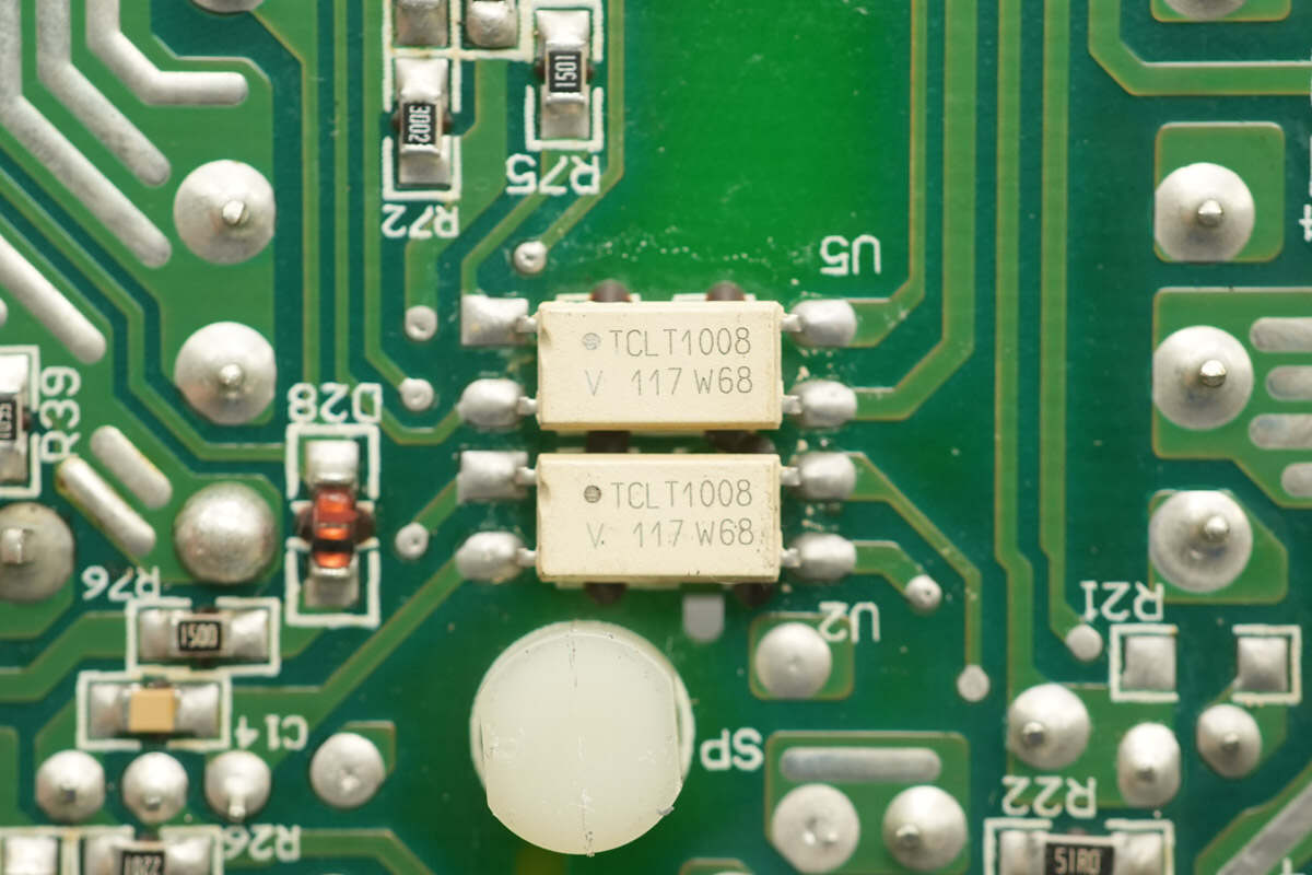
The VISHAY TCLT1008 optocouplers are used for output voltage feedback and functional control.
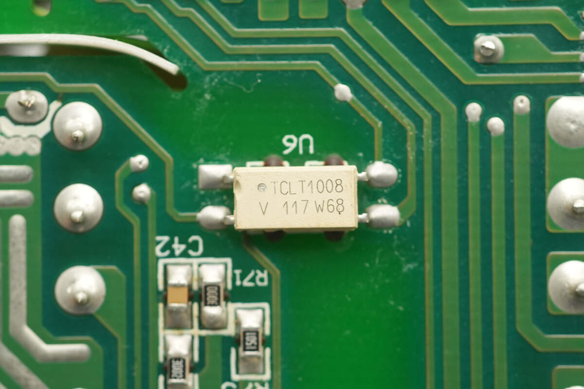
The other optocoupler has the same model.
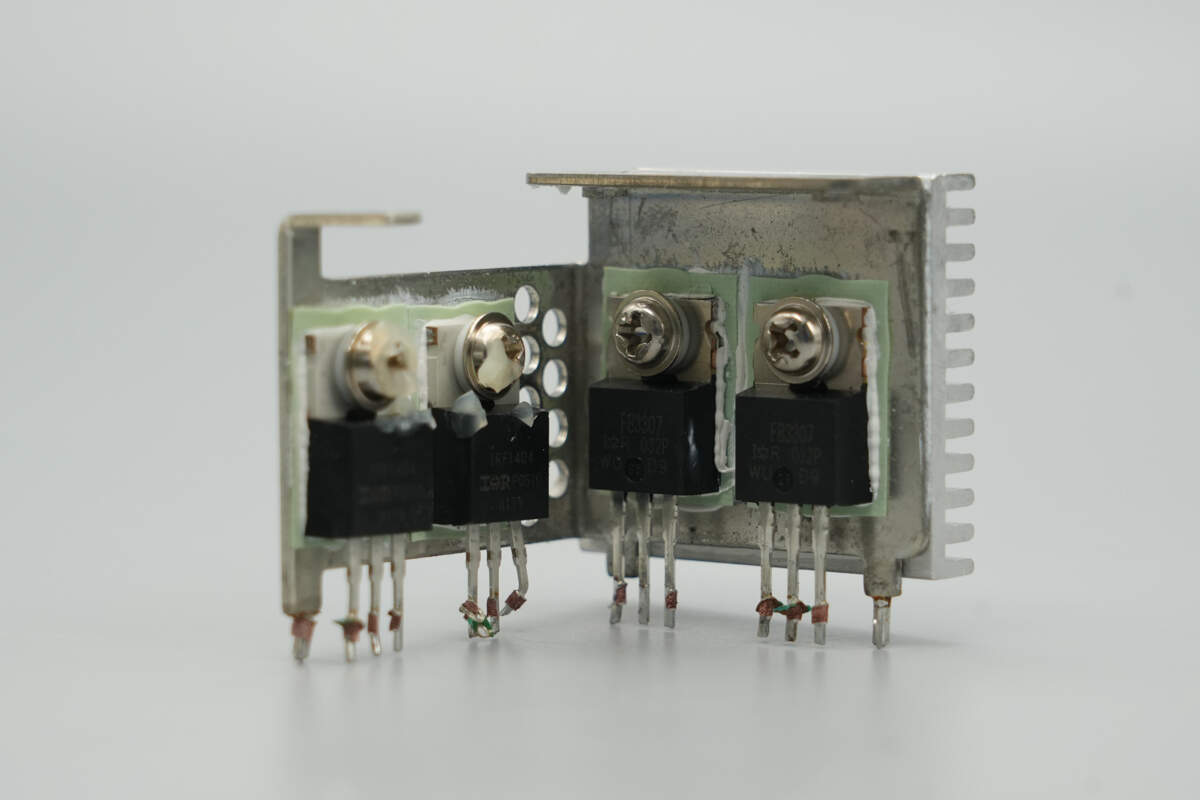
The heatsink houses the synchronous rectifiers and freewheeling MOSFETs.
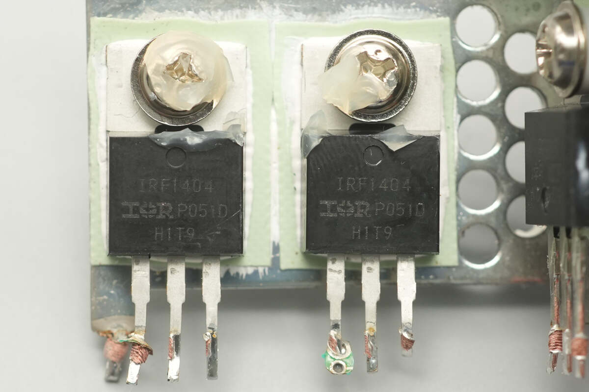
The synchronous rectifiers are sourced from Infineon, model IRF1404, NMOS type, with a voltage rating of 40V and an on-resistance of 4mΩ, housed in a TO-220AB package.
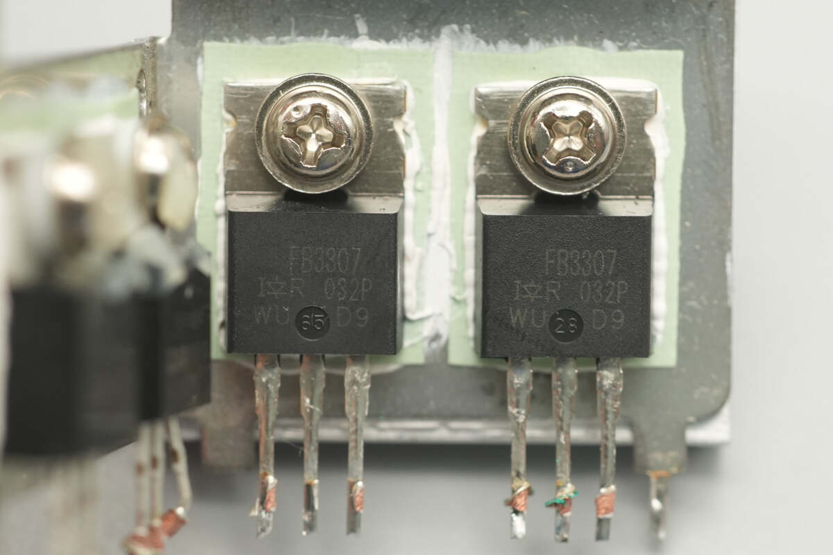
The freewheeling MOSFETs are sourced from Infineon, model IRFB3307, NMOS type, with a voltage rating of 75V and an on-resistance of 5mΩ, housed in a TO-220AB package.

The energy storage inductor is wound on a magnetic ring core.

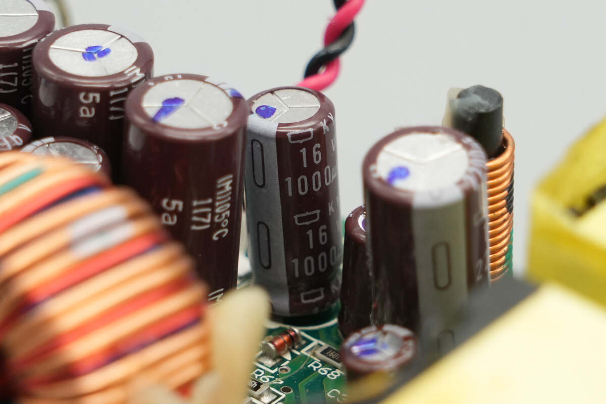
The output filter capacitors are sourced from NCC. The two capacitors on the inner side are rated at 16V 1000μF.

The three capacitors on the outer side are rated at 16V 2200μF.
The sampling resistor is used to detect the output current.
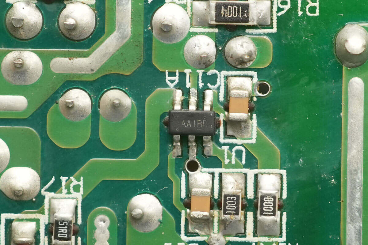
The standby power controller is sourced from Onsemi, marked with AAI, model SG6858. It features low standby power consumption, supports constant power output and loop compensation, requires minimal external components, and is housed in an SSOT-26 package.
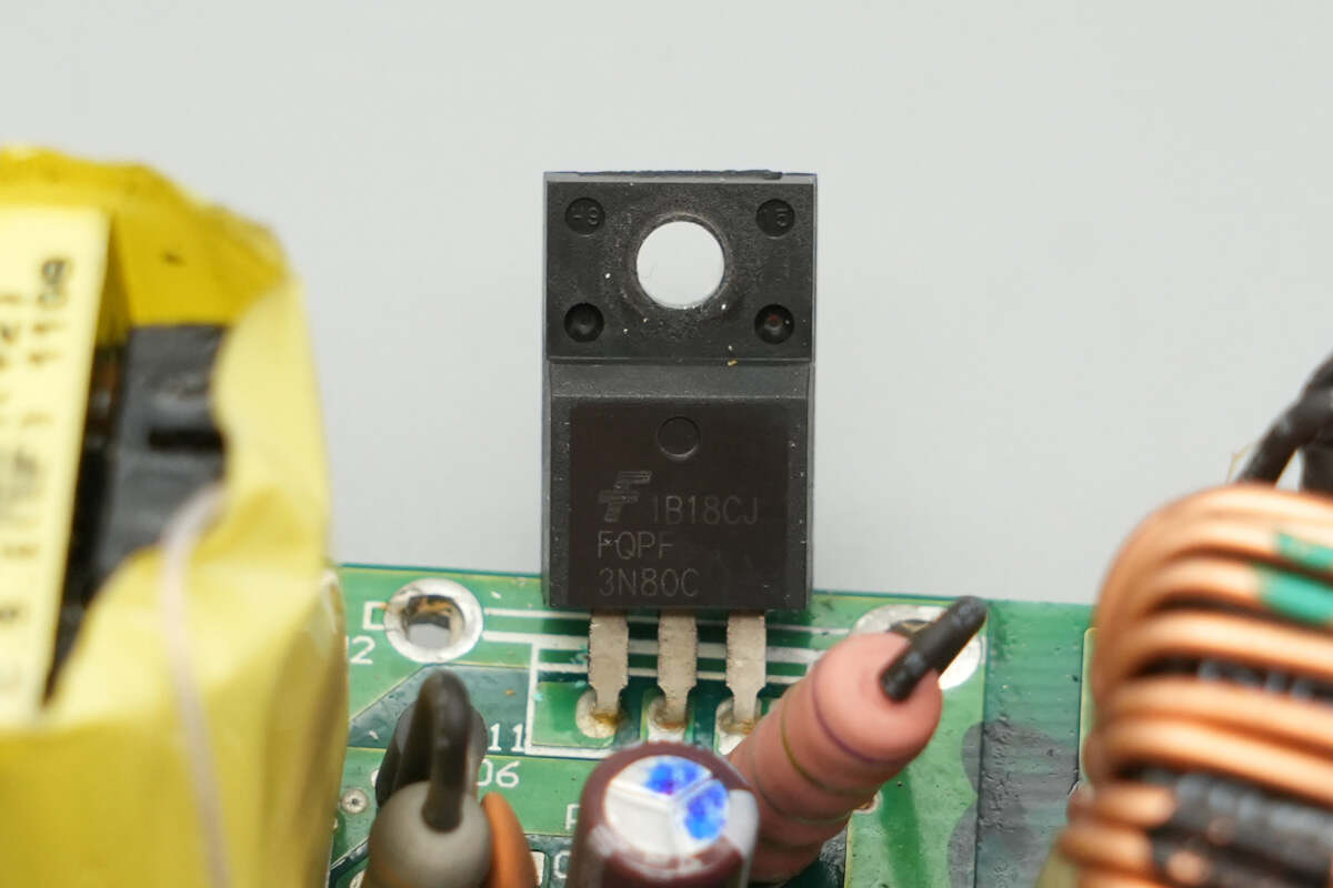
The standby power MOSFET is an Onsemi FQPF3N80C.

The transformer windings are insulated with tape.
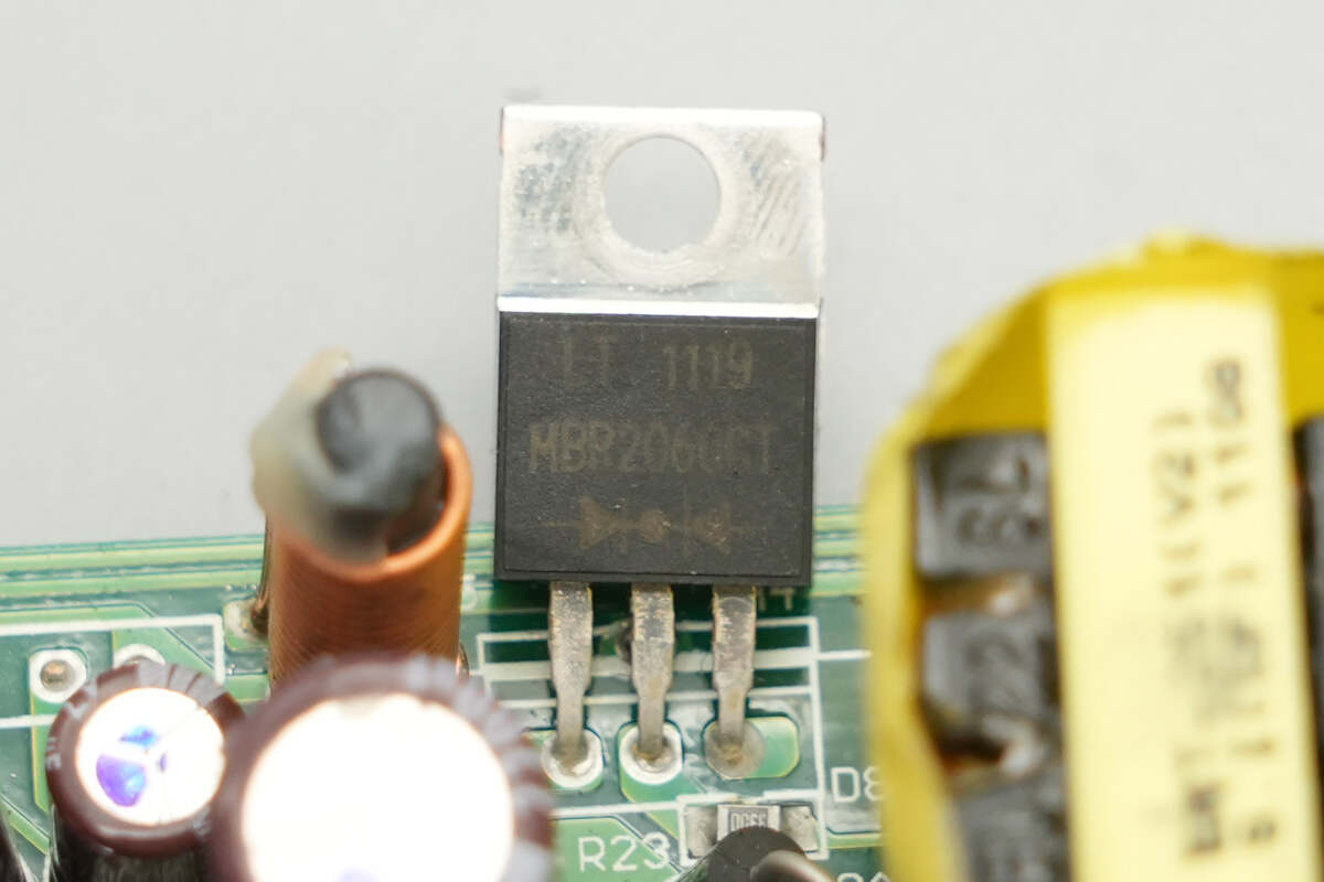
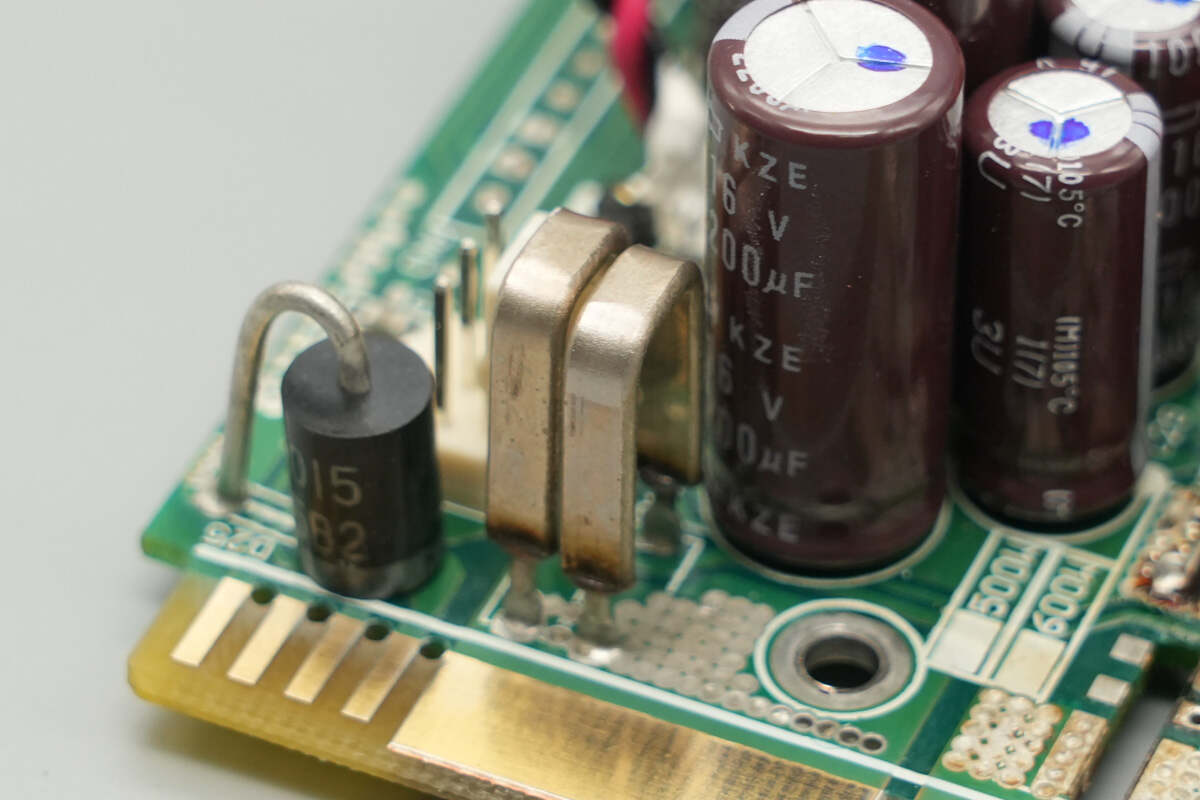
The rectifier is sourced from LITEON, model MBR2060CT, rated at 60V 20A, and housed in a TO-220AB package.
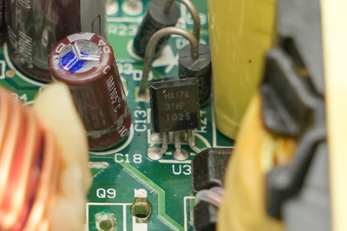
The RENESAS HA17431 voltage reference, combined with an optocoupler, is used for output voltage feedback.
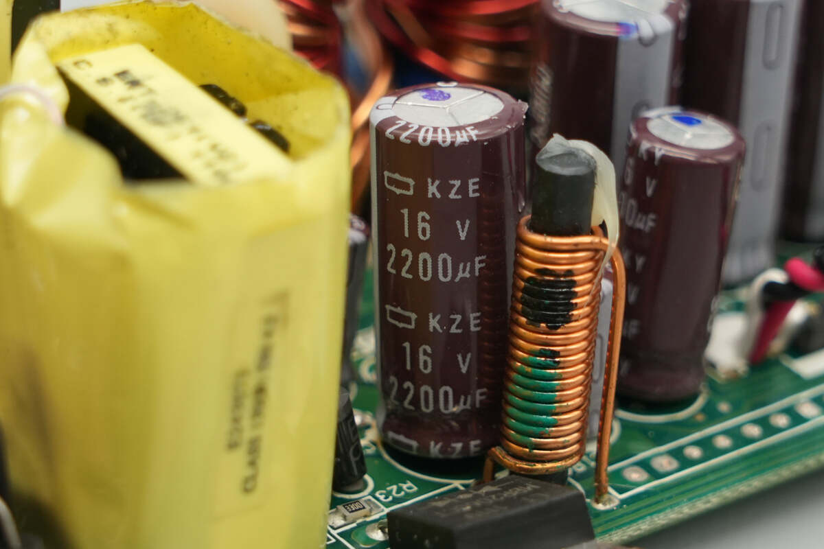
The standby power filter capacitor is rated at 16V 2200μF.

Close-up of the ferrite rod filter inductor.
The other filter capacitor is rated at 16V 1000μF.
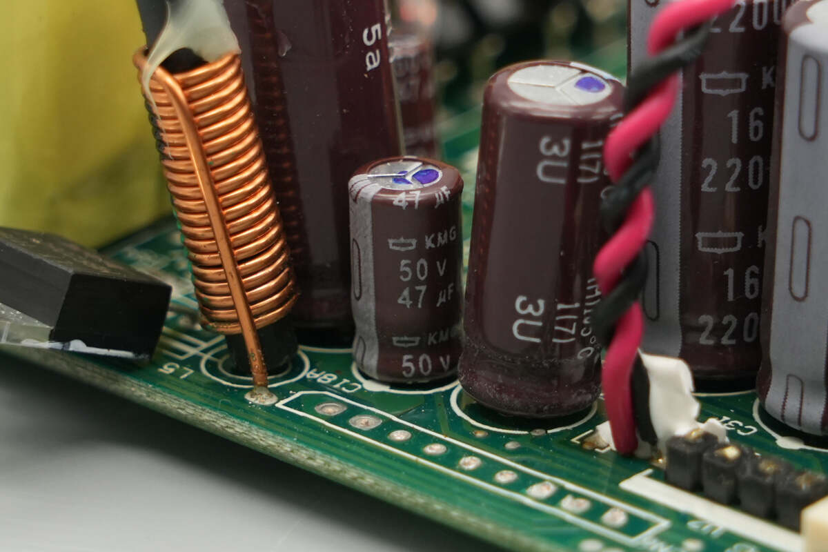
This filtering capacitor is rated at 50V 47μF.
The other filtering capacitor has the same specifications.
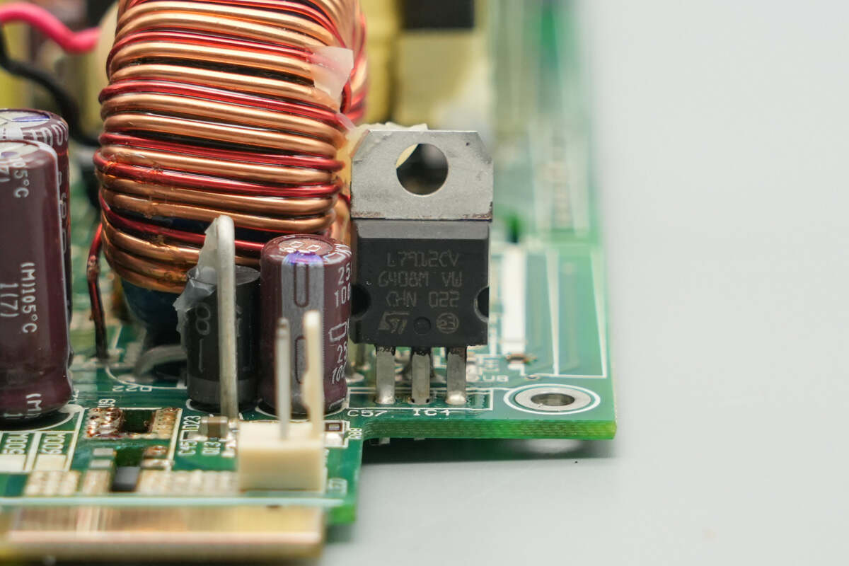
The output stage is equipped with an STMicro L7912CV voltage regulator chip, housed in a TO-220 package.

The output filter capacitor is rated at 25V 100μF.
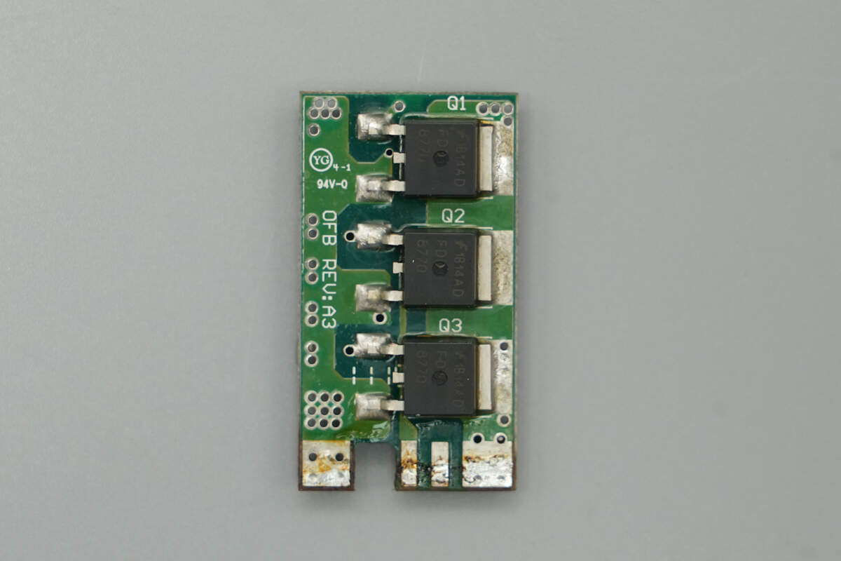
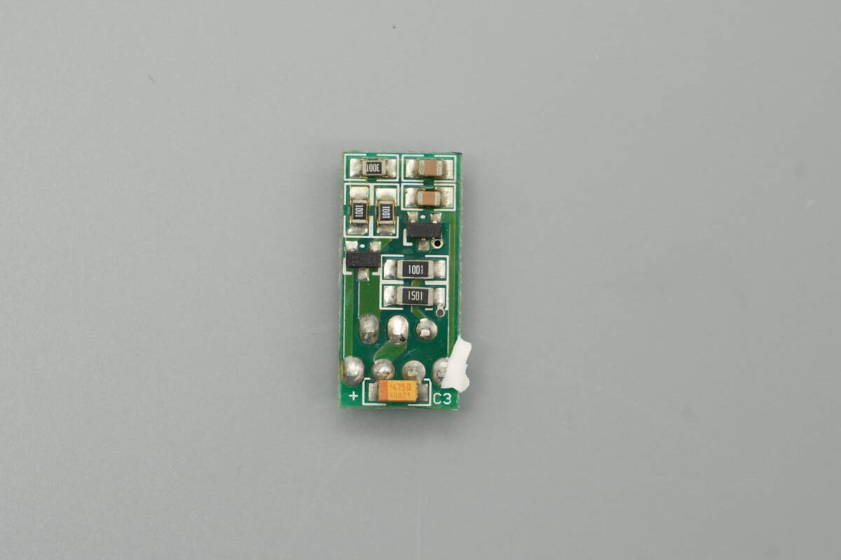
The output PCB, responsible for 12V power output control, features three MOSFETs on the front side for output regulation.
The back side is equipped with an ideal diode controller.
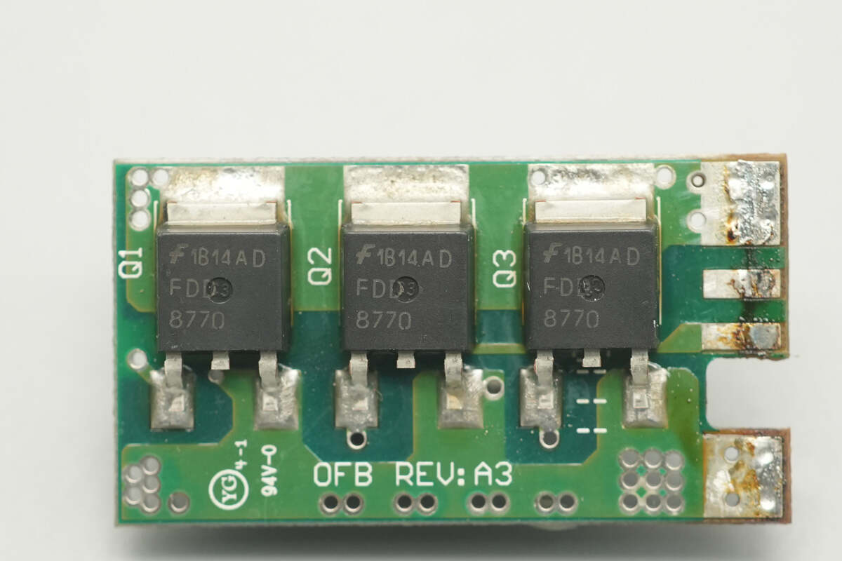
The control MOSFETs are sourced from Onsemi, model FDD8770, NMOS type, with a voltage rating of 25V and an on-resistance of 4mΩ, housed in a TO-252 package.

The ideal diode controller is sourced from Infineon, model IR5001S. It is a universal high-speed active ideal diode controller with a built-in NMOS driver, housed in an SO-8 package.

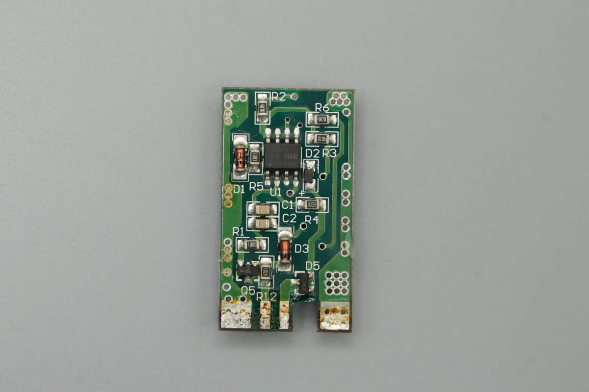
The front side of the other PCB features an operational amplifier and a potentiometer.
The back side contains diodes and other components.

The operational amplifier is sourced from STMicro, model LM324, a general-purpose quad op-amp housed in an SOIC-14 package.
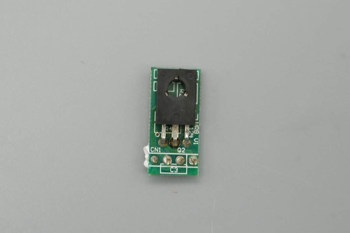
The PCB controlling the cooling fan is equipped with a MOSFET.
The back side is equipped with resistors, capacitors, and other components.

The transistor used for cooling fan control is model B772, a PNP type with a voltage rating of -40V, collector current of 3A, housed in a TO-126 package.

The power management chip is sourced from Weltrend, model WT7510. It is used for overvoltage detection on 3.3V, 5V, and 12V outputs, and housed in an SOP-8 package.
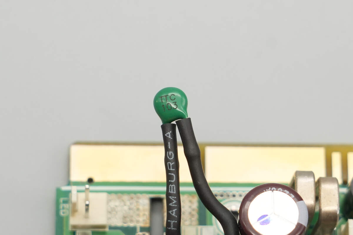
Close-up of the thermistor used for internal power supply temperature detection.
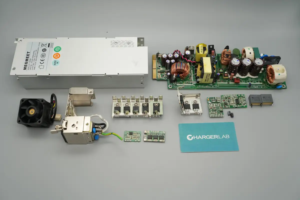
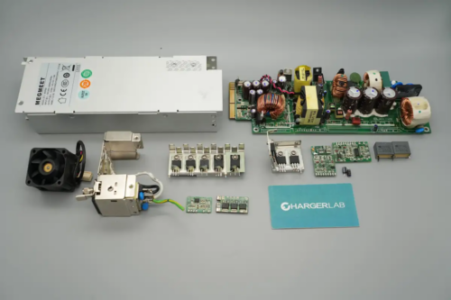
Well, those are all components of the MEGMEET 600W Switching Power Supply.
Summary of ChargerLAB
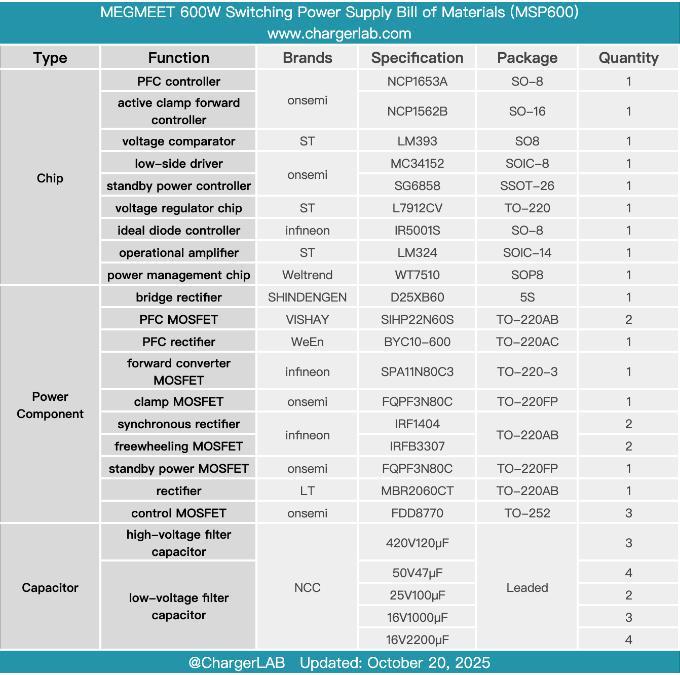
Here is the component list of the MEGMEET 600W Switching Power Supply for your convenience.
The module features a hot-swappable design and supports a wide input voltage range of 100–240V. It has a rated output voltage of 12V with an output current of 48A, and a standby output voltage of 5V with an output current of 4A. A cooling fan is installed at the input side, drawing air from the output side and blowing it out through the input side for heat dissipation. The output side is equipped with a gold finger connector.
After taking it apart, we found that it adopts a PFC + active clamp forward + self-driven synchronous rectification architecture. All control chips are sourced from Onsemi, using the NCP1653A PFC controller paired with the NCP1652B forward converter controller. The PFC MOSFETs are VISHAY SIHP22N60S, the PFC rectifier is RePower BYC10-600, the forward converter MOSFET is Infineon SPA11N80C3, and the clamp MOSFET is Onsemi FQPF3N80C.
The synchronous rectifiers use Infineon IRF1404, while the freewheeling MOSFETs use IRFB3307. The standby power controller is Onsemi SG6858, and the rectifier is LITEON MBR2060CT. The PFC and forward converter control PCBs are insulated with tape. All capacitors are sourced from NCC. The components are all from leading international brands, with solid material quality and workmanship.
Related Articles:
1. Teardown of vivo 120W Multi-Port GaN Charger (V12060L0D0-CN)
2. Teardown of Xiaomi 30W 2-in-1 Magnetic Wireless Charger (MDY-20-EC)
3. Teardown of Xiaomi 30W Car Magnetic Wireless Charger (MDY-20-ED)