Introduction
Recently, we acquired the MEAN WELL 1500W Switching Power Supply, model SE-1500-24. It features an input voltage range of 200-240V, an output voltage of 24V, and an output current of 62.5A. The power supply is housed in an aluminum alloy casing and includes internal cooling fans.
It is equipped with a control terminal, offering DC OK signal output, remote on/off control, and remote sensing capabilities. These features allow for monitoring operational status and remote switching control, providing greater flexibility in use. In this teardown, we'll explore the internal design and components of this power supply.
Product Appearance

The casing is made of aluminum alloy and is secured with screws. The bottom features terminal blocks for wiring, with an information label affixed.
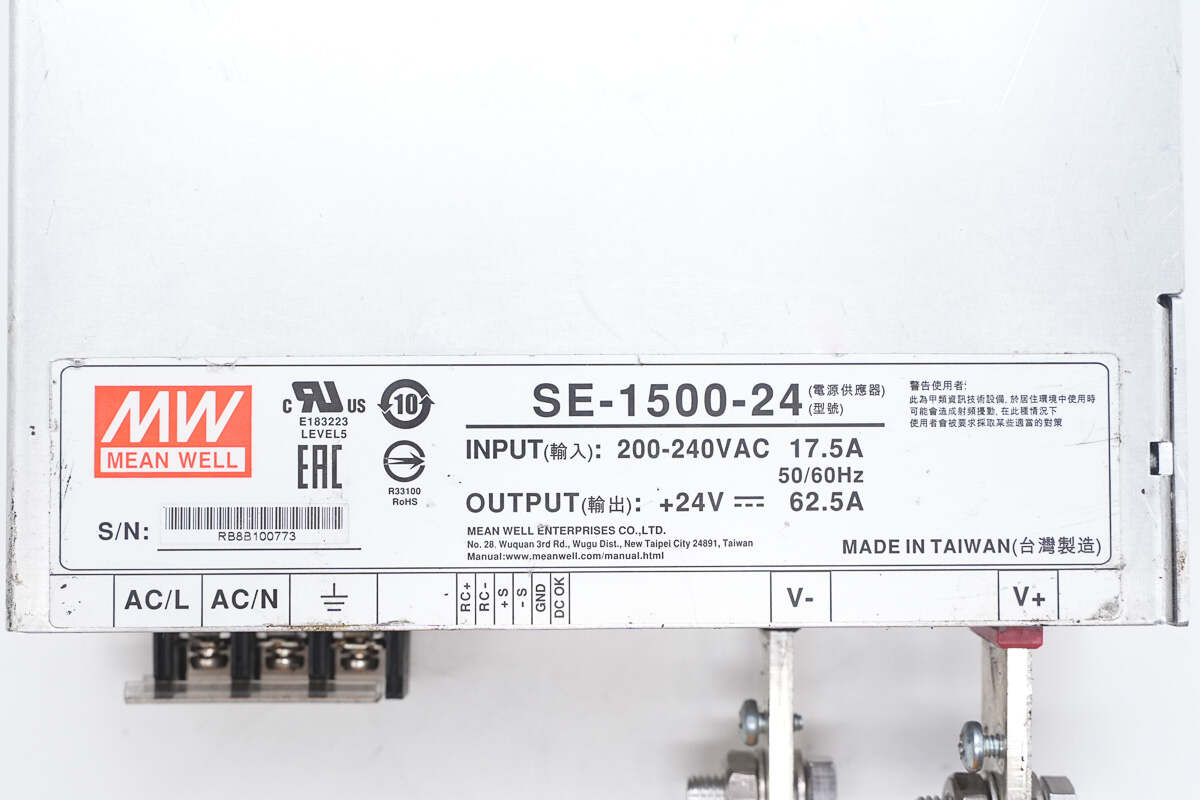
Model: SE-1500-24
Input: 200-240VAC 17.5A 50/60Hz
Output: 24V 62.5A

The rear cover has holes for securing the cooling fan.
The rear cover is secured with screws.
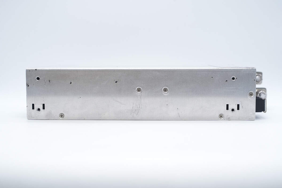
The sides also have screws for mounting.

The top features a cooling fan, protected by a mesh cover, and is secured with screws.
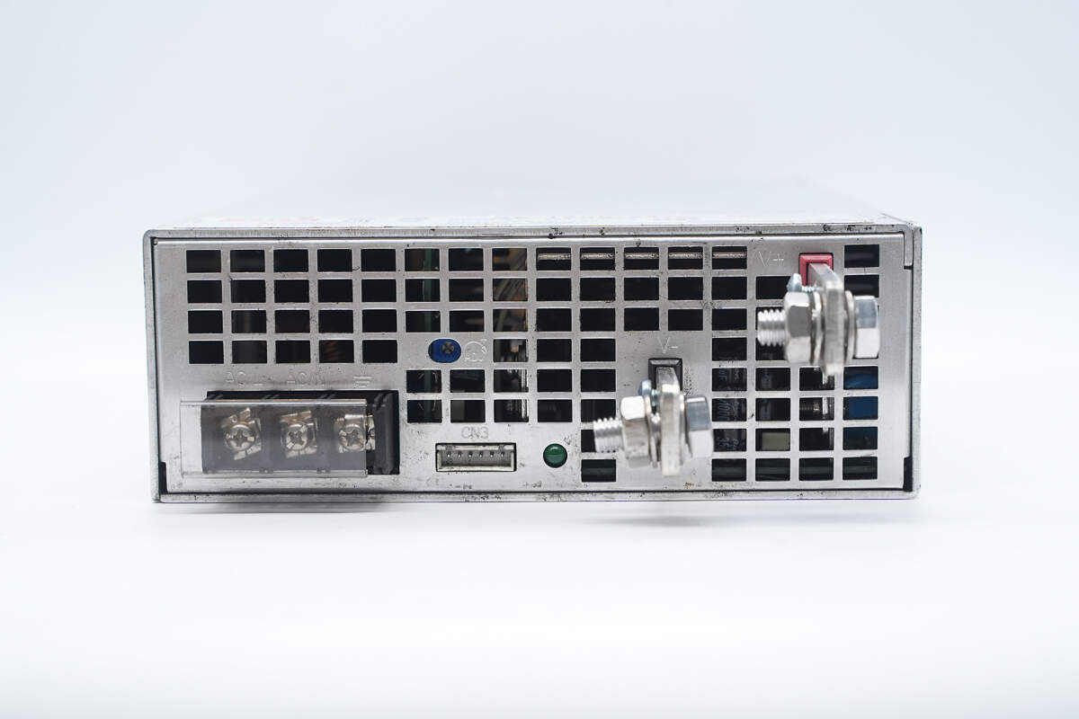
The bottom of the module has AC input terminals, DC output terminal posts, and a control terminal. It also features several rectangular openings for airflow.

The AC input terminals are equipped with a transparent insulating cover.
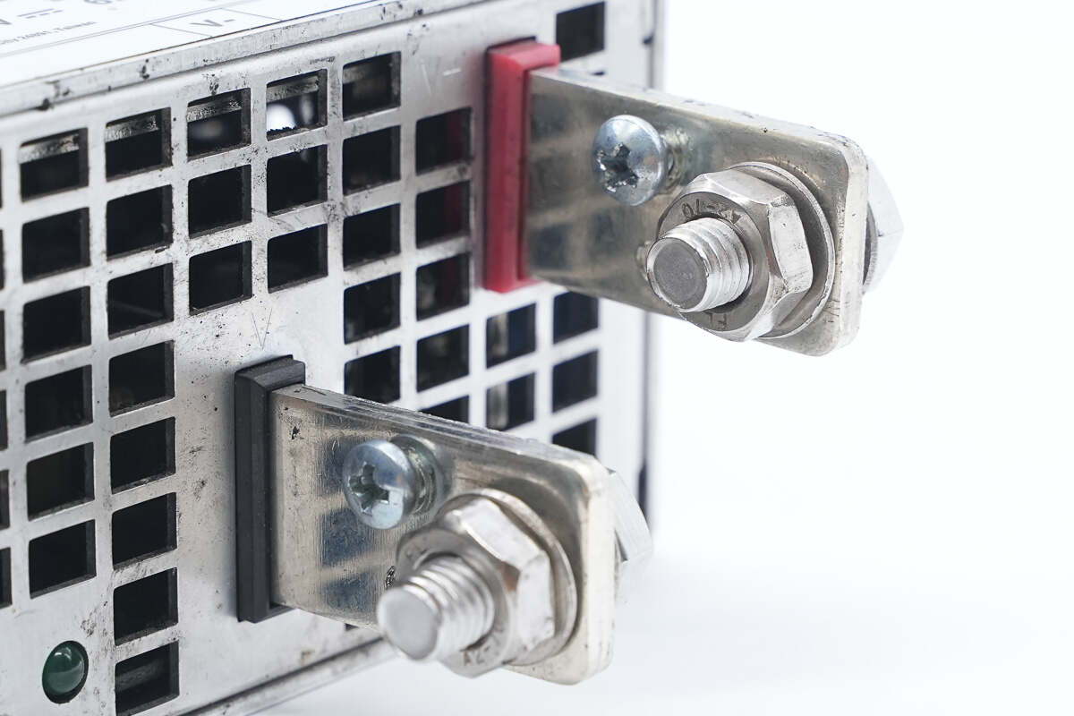
The DC output terminal posts are marked with red and black to indicate the positive and negative poles.
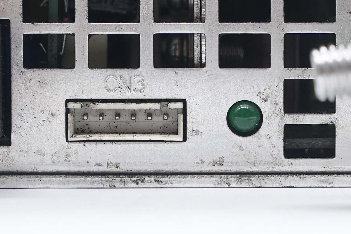
Close-up of the control terminal and indicator light.
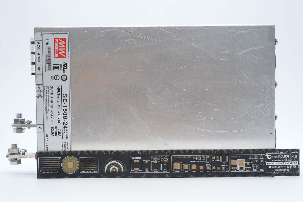
The length is about 280 mm (11.024 inches).

The width is about 177.9 mm (7.0039 inches).
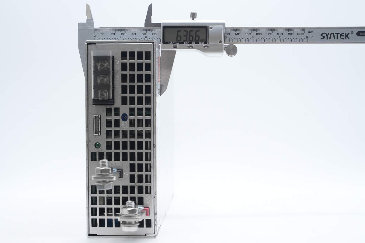
The thickness is about 63.7 mm (2.51 inches).
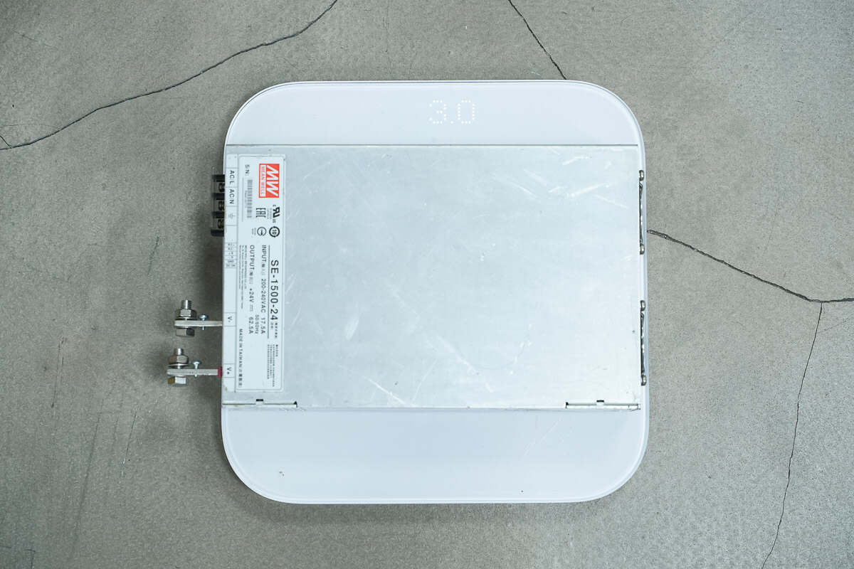
The weight is about 3 kg.
Teardown
Next, let's take it apart to see its internal components and structure.
First, remove the screws and take off the casing.
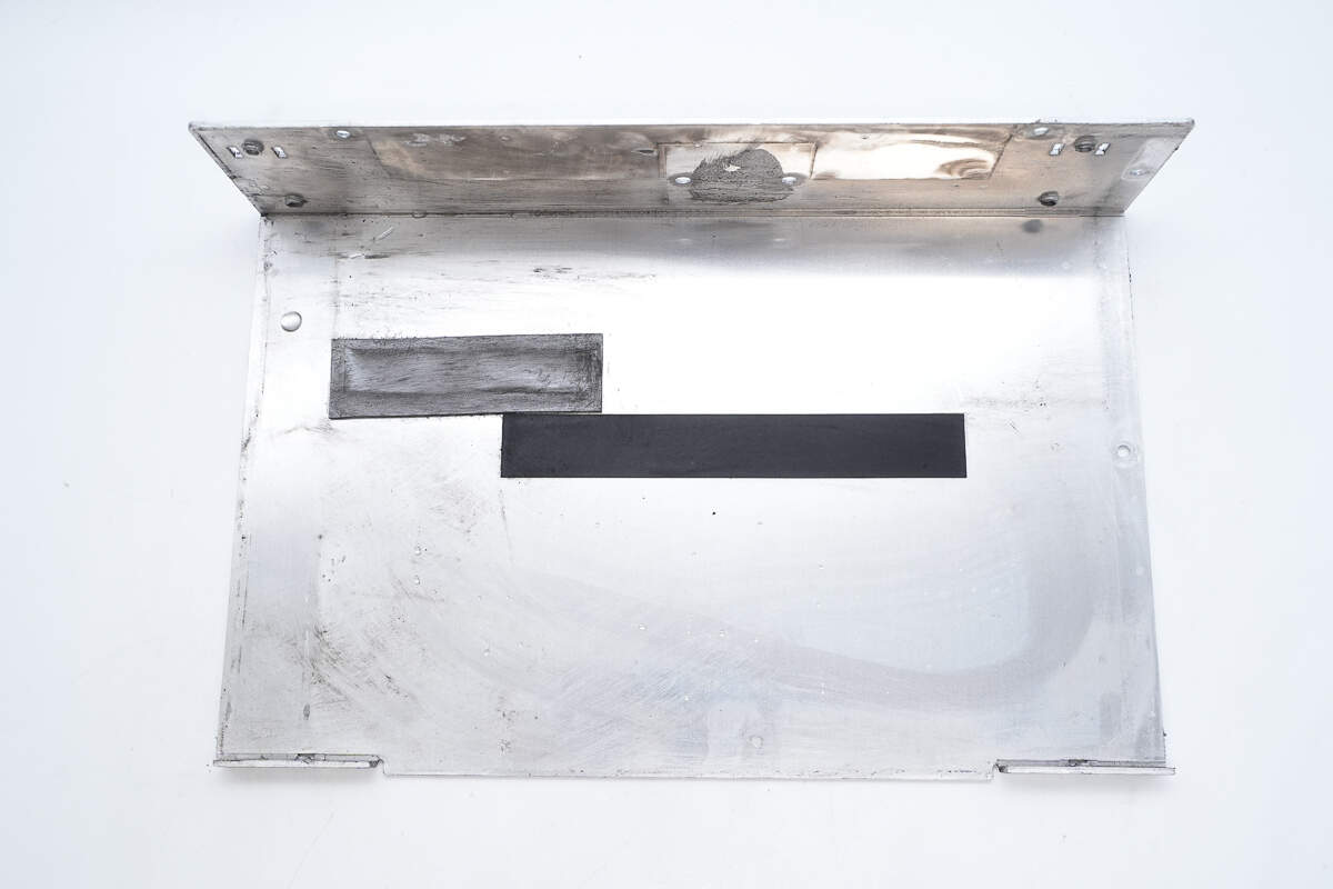
The interior of the casing is equipped with thermal pads.

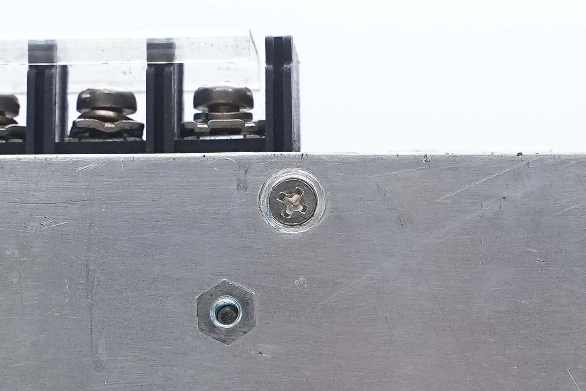
The PCBA module is secured inside the casing with screws.

Close-up of the screw securing the PCBA module.

The temperature switch is secured to the rectifier's heatsink with a screw and a metal plate.
The two cooling fans are connected via connectors.
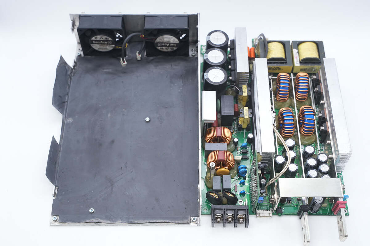
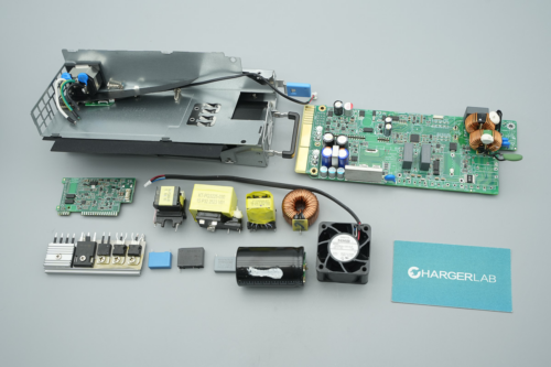
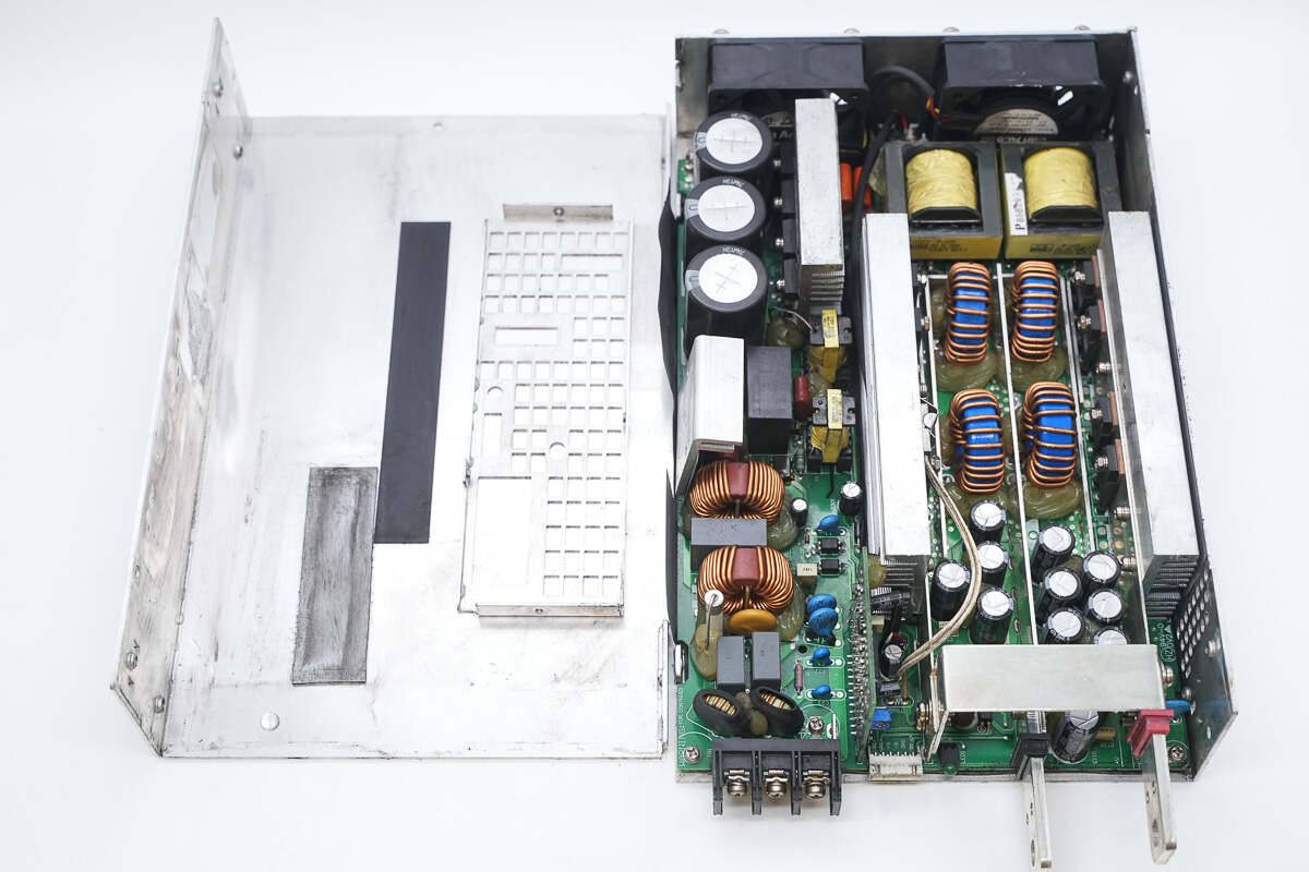
Remove the PCBA module. The interior of the casing is insulated with Mylar sheets.
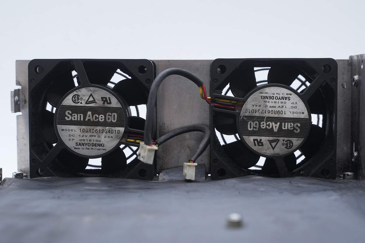
The two cooling fans are from SANYO DENKI, part of the San Ace 60 series, with a specification of 12V 0.24A.

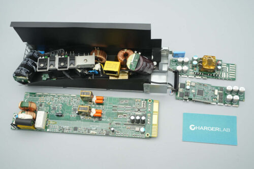
The upper left corner of the PCBA module's front face houses the AC input, along with wiring terminals, filter inductors, safety X2 capacitors, fuses, varistors, and common mode chokes. The center section contains the bridge rectifier, relay, and thermistor. The right side is equipped with high-voltage filter capacitors and primary MOSFETs.
Below the MOSFETs are the transformers. On the left side are the rectifier diodes and heatsinks. The center contains filter inductors, filter capacitors, and on the left side, the DC output terminal posts. A control PCB is located between the AC input terminal and the DC output terminal posts.

On the back of the PCBA module, exposed copper with solder enhances current-carrying capacity. There is a driver chip used to drive the isolation transformer.

Remove the primary MOSFETs, bridge rectifier, control PCB, relay, and safety X2 capacitors.
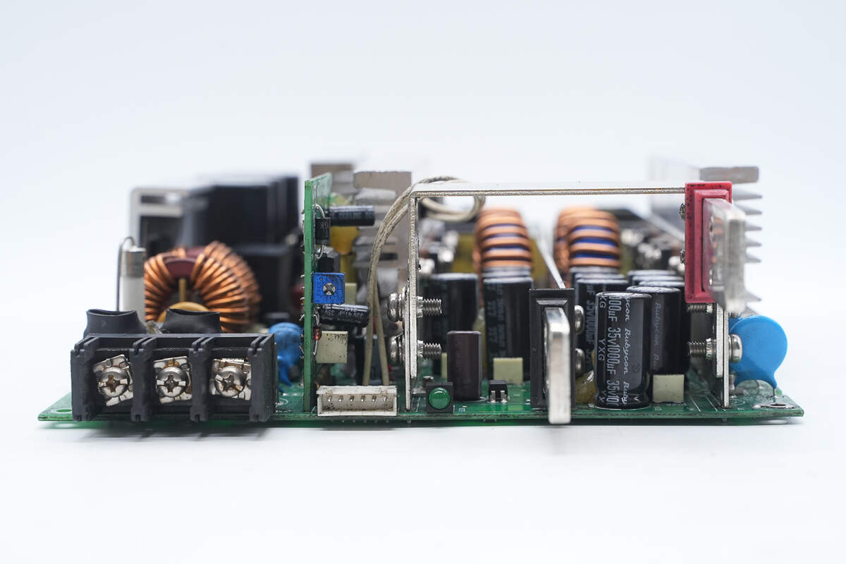
A side view shows the following: On the left side, there are AC input terminals. In the center, there is the control PCB and control terminals. On the right side, there are filter capacitors and DC output terminal posts.
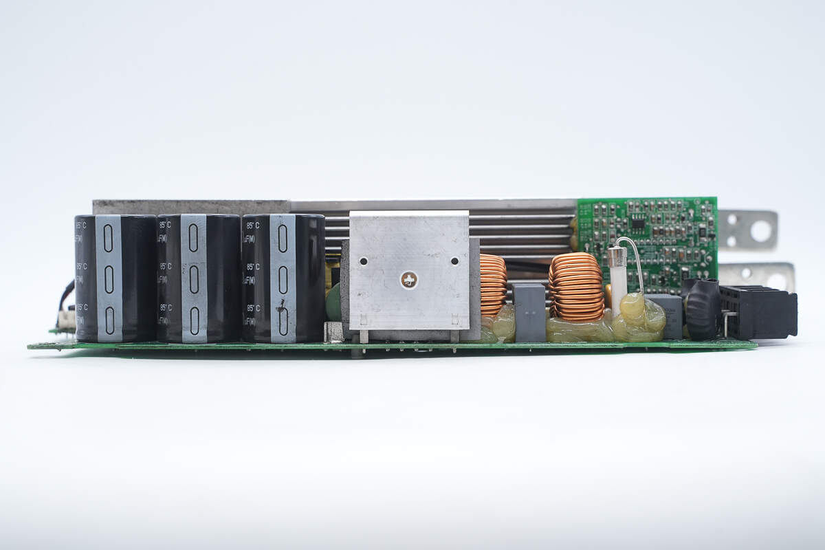
The other side features filter inductors, a fuse, common mode chokes, a bridge rectifier, and high-voltage filter capacitors.

Close-up of the AC input terminal posts.

The filter inductors are wound with magnetic cores and insulated with heat-shrink tubing.
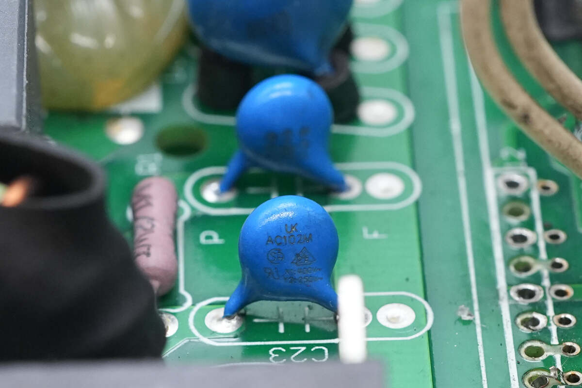
Close-up of the blue Y capacitors.
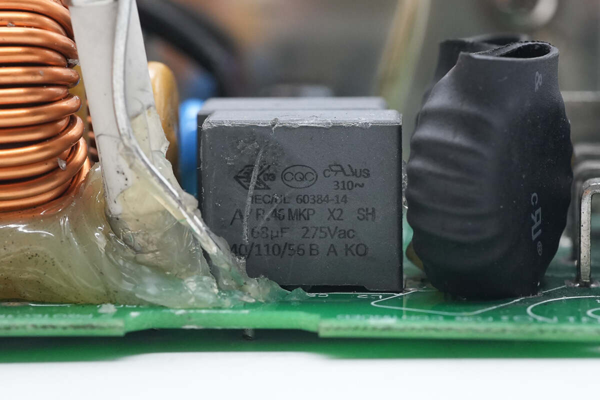
Two safety X2 capacitors are connected in parallel, with a rating of 0.68μF.

Close-up of the blue Y capacitors.

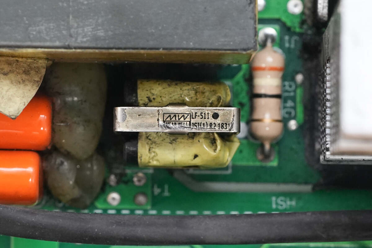
The input fuse is rated at 25A.

The TVR14471 varistor is used to absorb overvoltage surges.
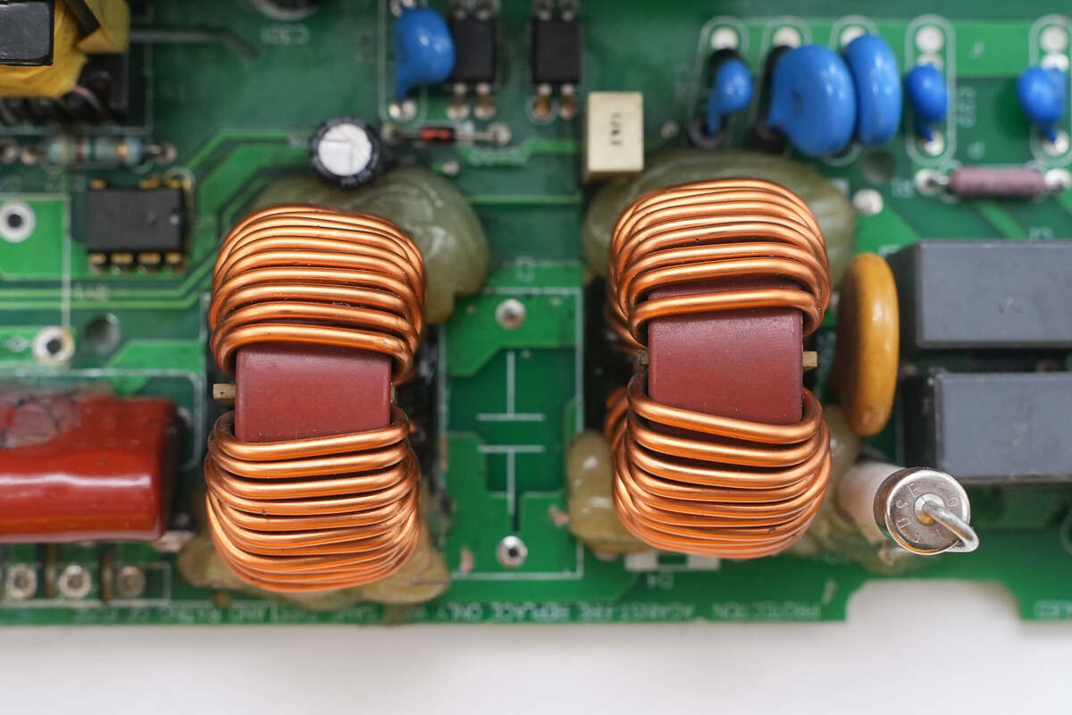
The two common mode chokes are wound with enameled wire.
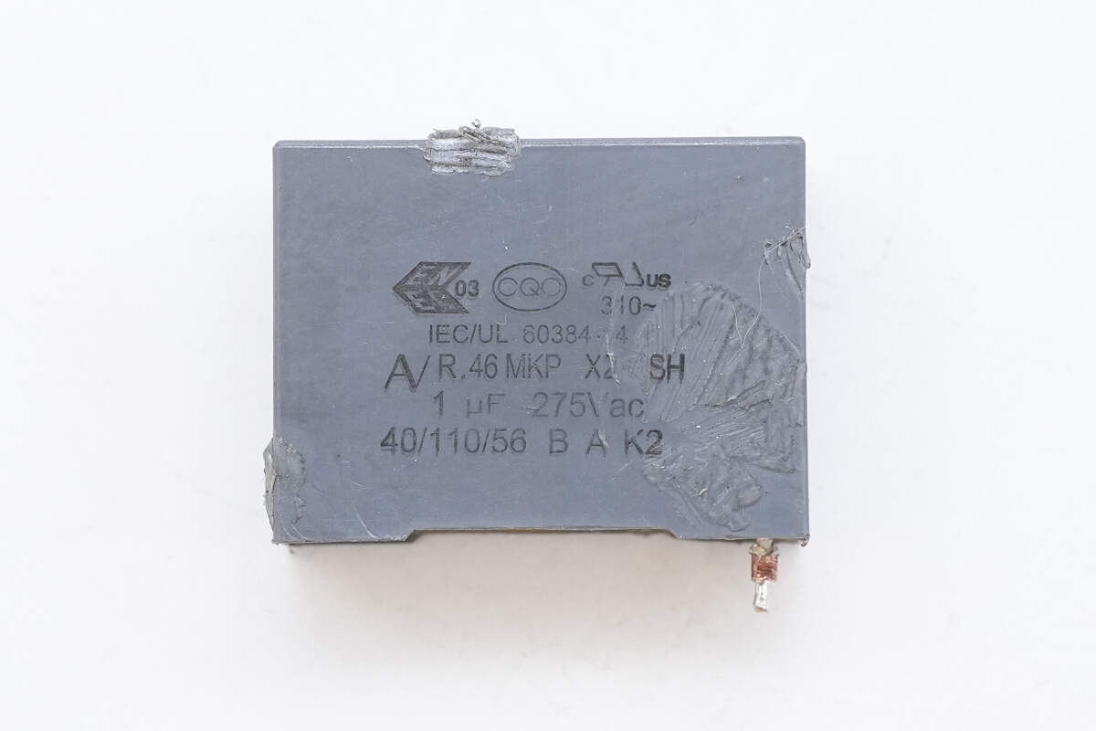
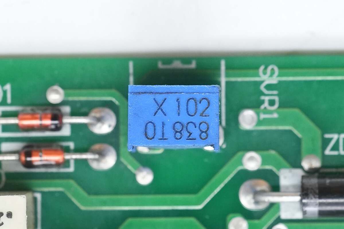
The safety X2 capacitors are rated at 1μF.
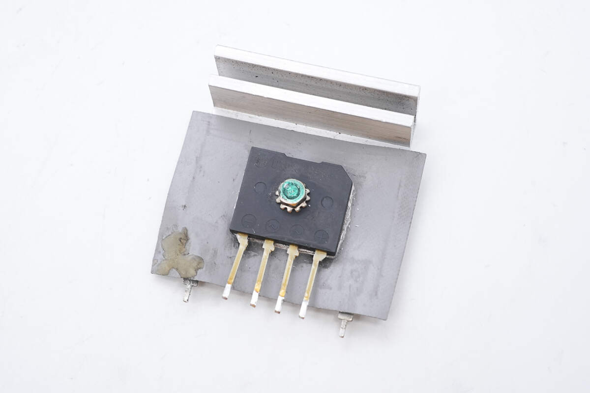
The bridge rectifier is secured to the heatsink with a screw.
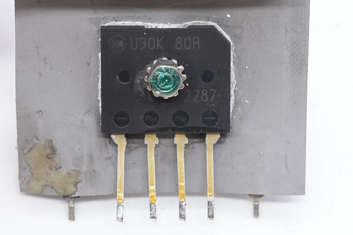
The bridge rectifier is from Shindengen, model U30K80R, with a rating of 30A 800V, and is packaged in a D6K form factor.
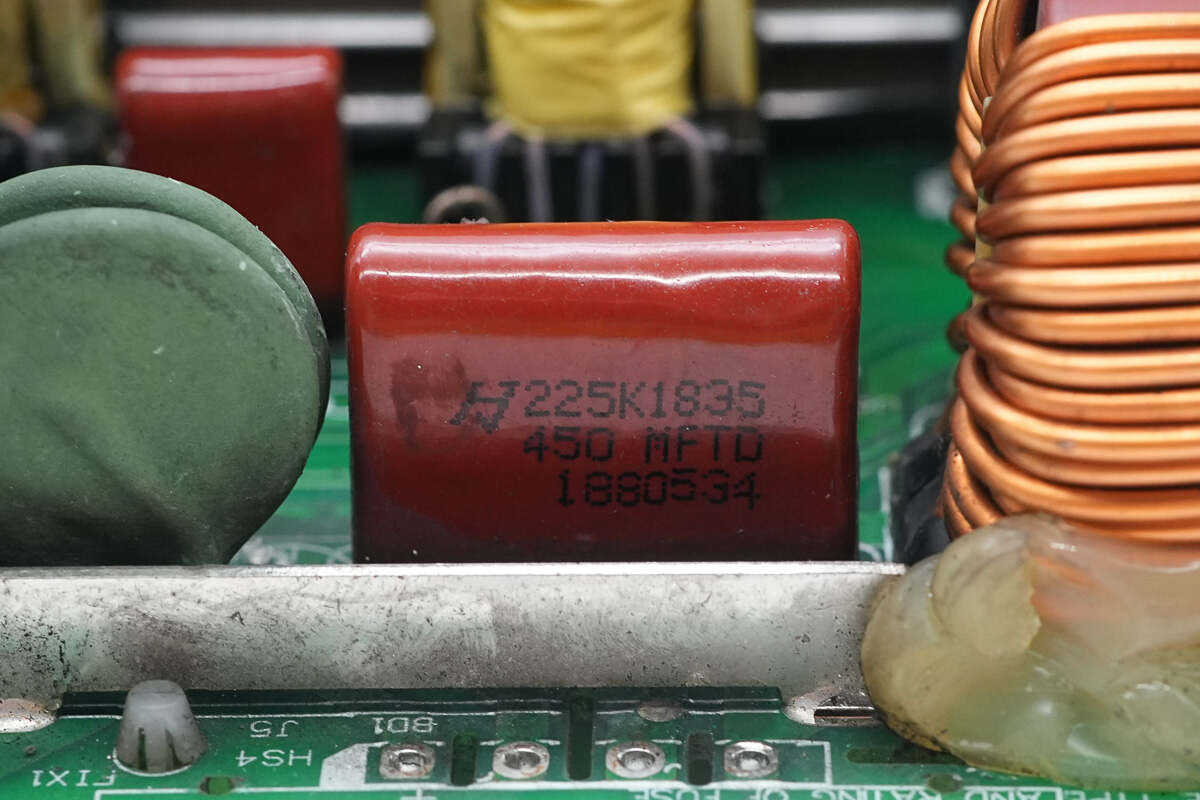
The film capacitor is from HJC, with a specification of 2.2μF 450V.
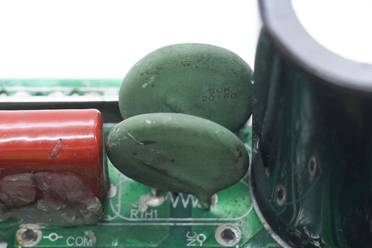
The Thinking SCK20160 thermistor is used to suppress inrush current during power-up.
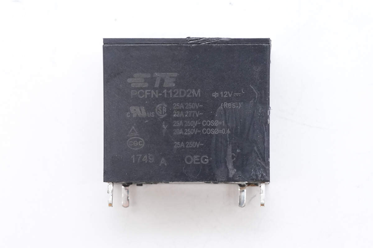
The relay is from TE, model PCFN-112D2M, with a contact rating of 25A 250V and a coil voltage of 12V.

The other side features the switch-mode transformer, MOSFETs, and high-voltage filter capacitors.
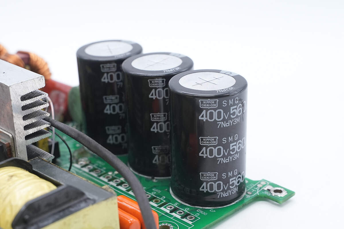
The high-voltage filter capacitors are from NCC, part of the SMQ series of compact electrolytic capacitors, with a specification of 400V 560μF.
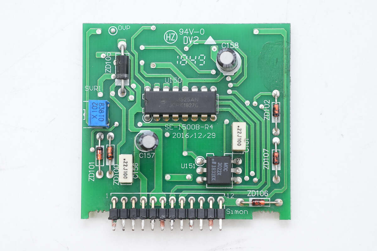
The front of the control PCB features a potentiometer, a PWM controller, and an isolation optocoupler.

The back of the control PCB features a dual op-amp.
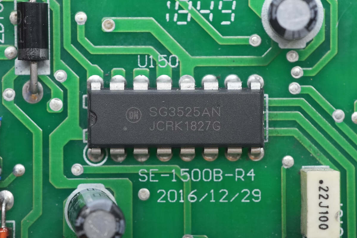
The PWM controller is from Onsemi, model SG3525A. It features an integrated voltage reference, supports external clock synchronization, and includes a soft start circuit. It is packaged in a PDIP-16 form factor.
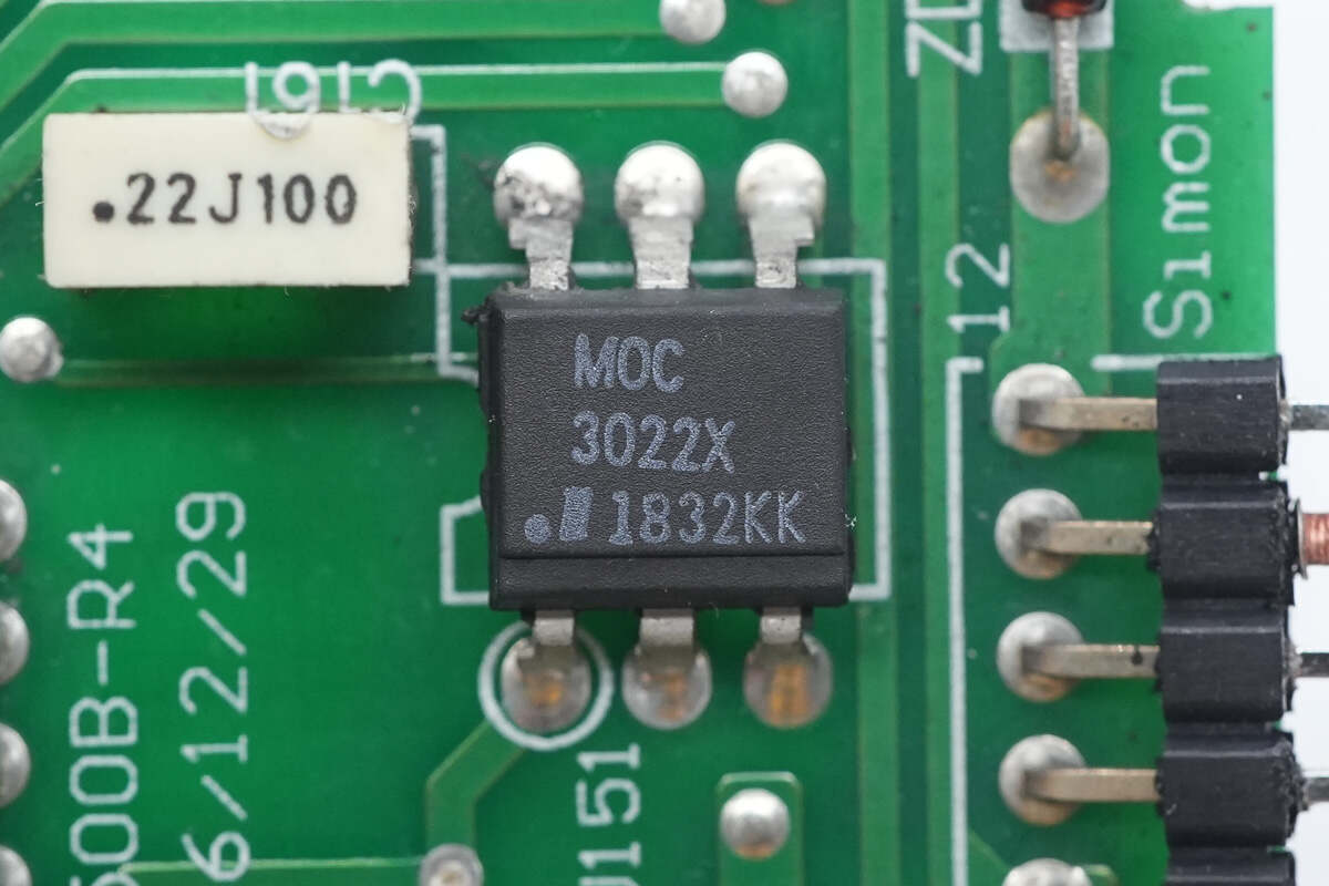
The isolation optocoupler is marked with MOC3022X.

The Op-Amp is from STMicro, model LM258A. It is a low-power dual operational amplifier, packaged in an SO8 form factor.
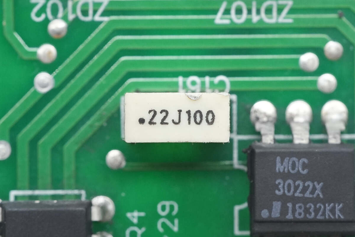
The film capacitor is rated at 0.22μF 100V.
Close-up of the potentiometer for adjusting the output voltage.
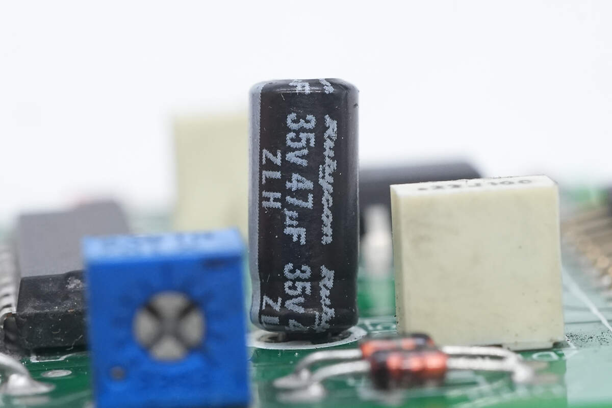
The power supply filter capacitor is from Rubycon, with a specification of 35V 47μF.
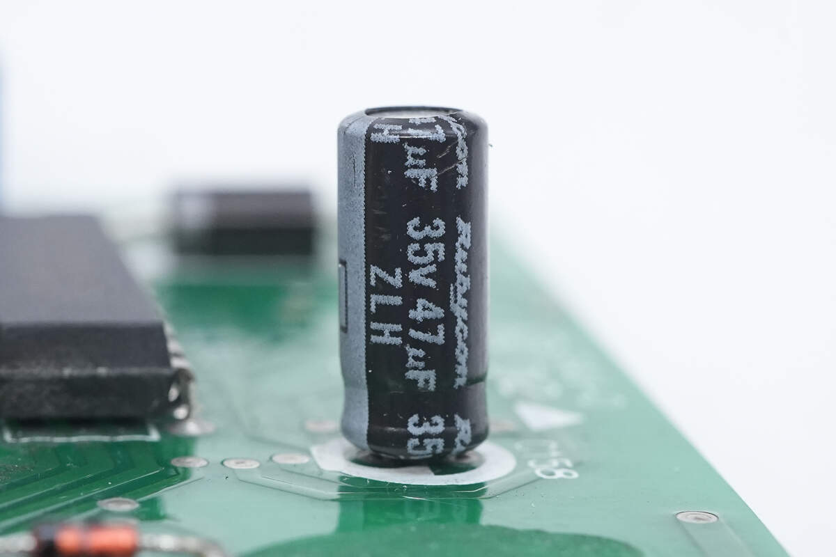
The other filter capacitor has the same specification.
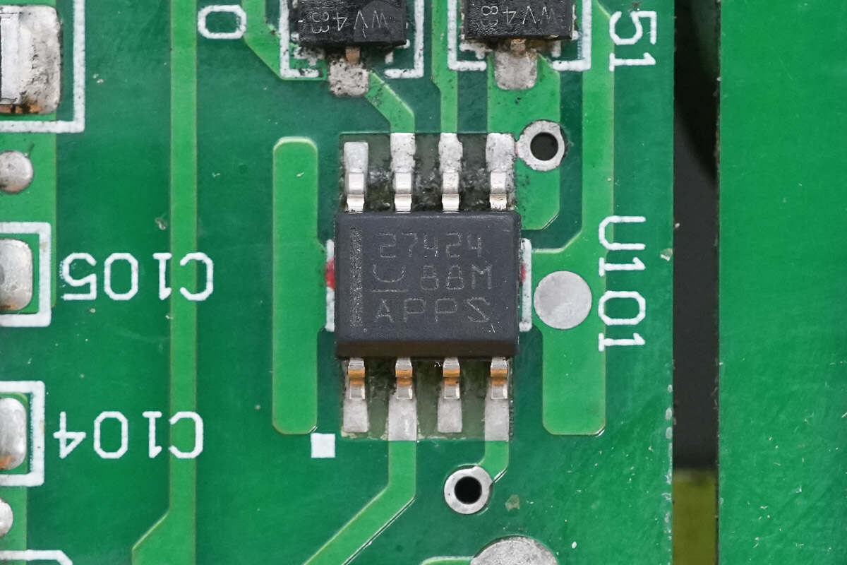
The driver chip is from Texas Instruments, model UCC27424. It is a dual-channel gate driver with a 4A output current, used to drive the isolation transformer, and is packaged in an SOIC8 form factor.

Close-up of the isolation transformer.
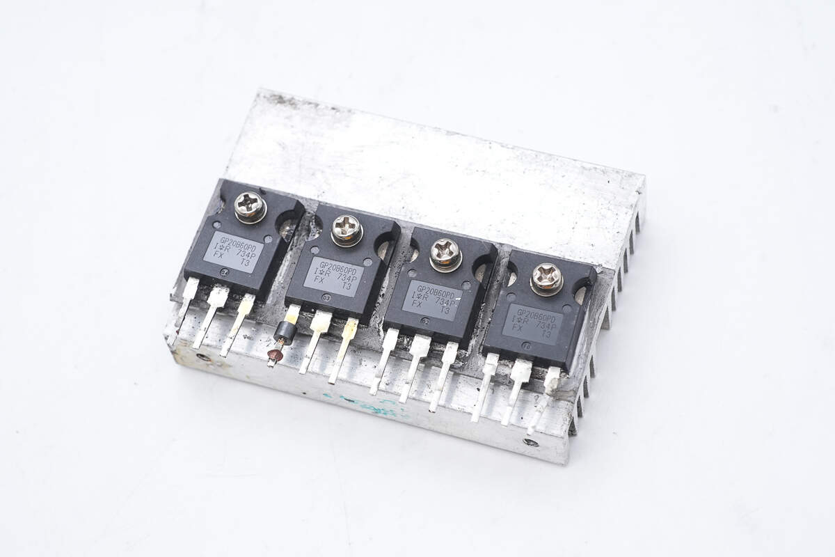
The primary MOSFETs are secured to the heatsink with screws.
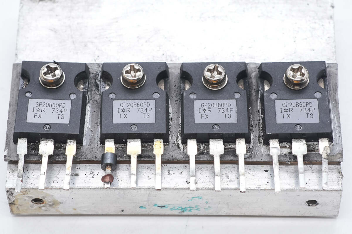
The MOSFETs are from Infineon, model IRGP20B60PD. They are IGBTs with a rating of 600V 20A, packaged in TO-247AC form, supporting a switching frequency of 150kHz. These are suitable for PFC and ZVS switch-mode power supply applications.
The current transformer is used to detect the primary current.
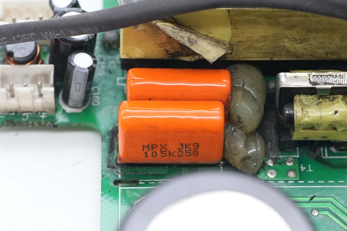
The film capacitor is rated at 1μF 250V.

Close-up of the two transformers.

The heatsink on the side is for cooling the rectifiers.

Four rectifiers are mounted on the heatsink.
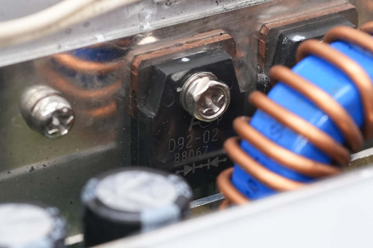
The rectifiers are from Fuji Electric, model ESAD92-02R. They are rated at 200V 20A and are packaged in a TO-3P form factor.

The heatsink on the other side also has four rectifiers mounted.
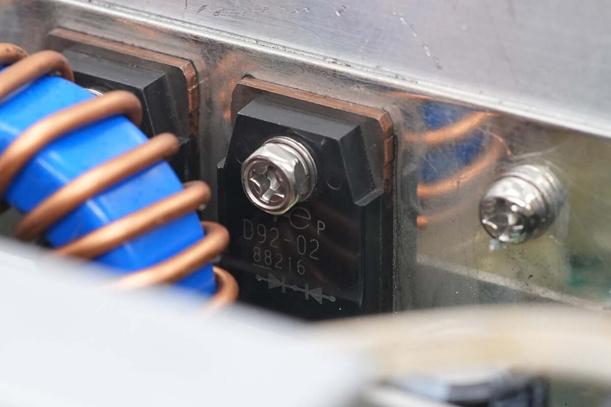
The rectifiers are of the same model.

The inductors are wound with enameled wire, and the bottom is reinforced with glue.

The output side is equipped with 12 electrolytic capacitors.
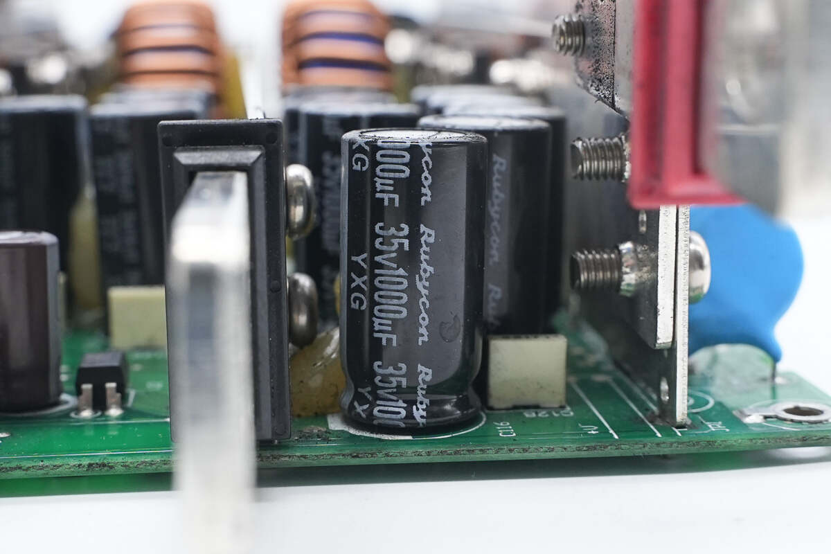
The capacitors are from Rubycon, part of the YXG low-ESR electrolytic capacitor series, with a specification of 35V 1000μF.
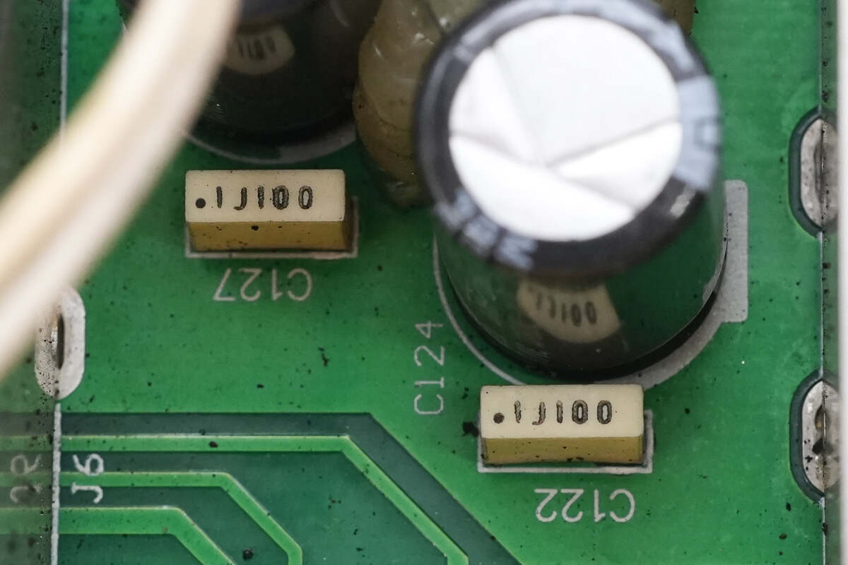
The electrolytic capacitors are parallel to 0.1μF 100V film capacitors for filtering.
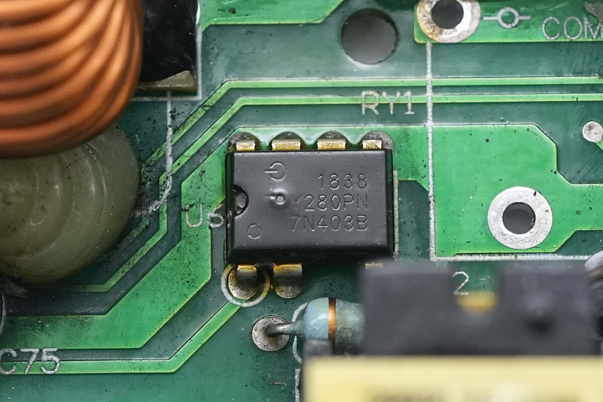
The auxiliary power chip is from PI, model TNY280PN. It is part of the TinySwitch-3 series, with an integrated MOSFET, and is packaged in a DIP-8C form factor.

The film capacitor is rated at 0.47μF 450V.

Close-up of the auxiliary power transformer.
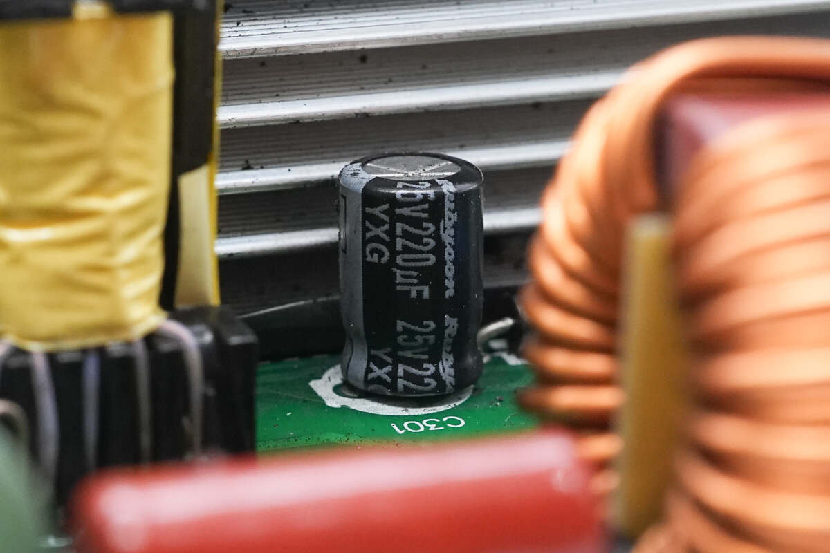
The output filter capacitor is rated at 25V 220μF.
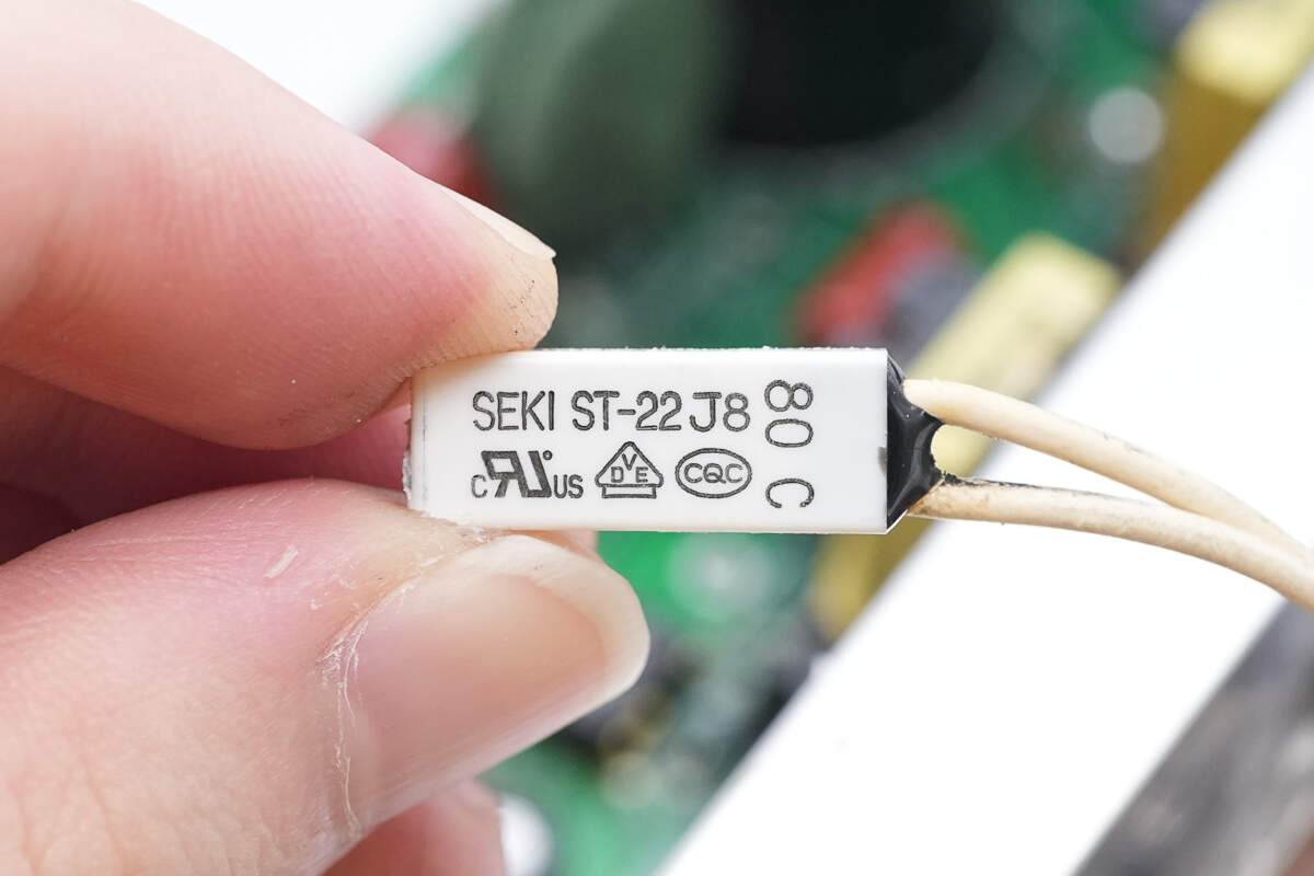
The thermal protector is from SEKI, model ST22, with a triggering temperature of 80°C. It is used for temperature protection of the rectifiers.
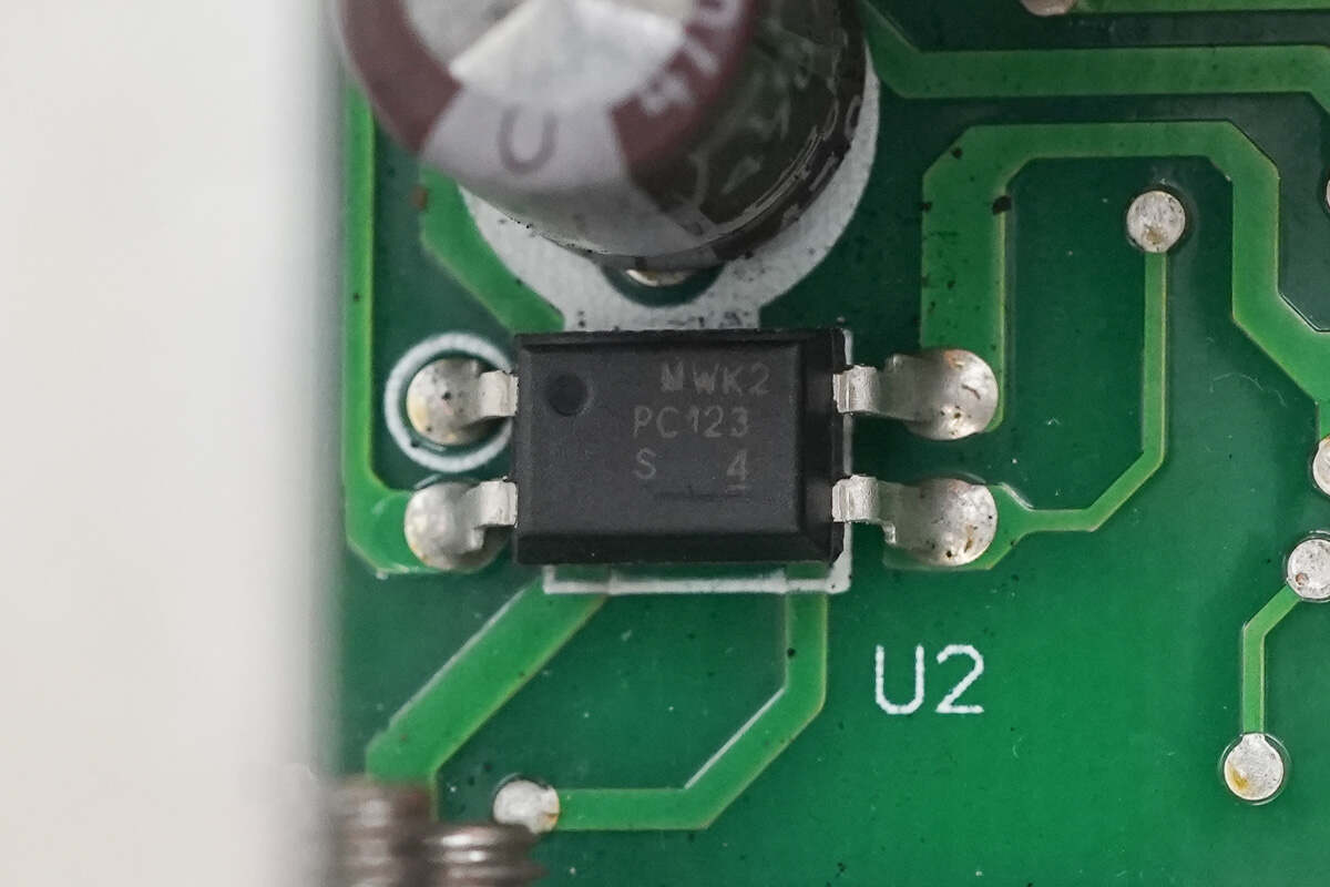
Close-up of the PC123 feedback optocoupler.
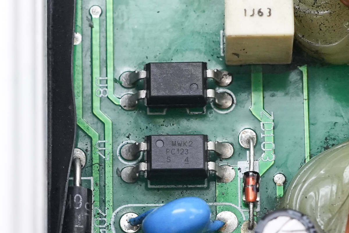
Close-up of the two optocouplers of the same model.
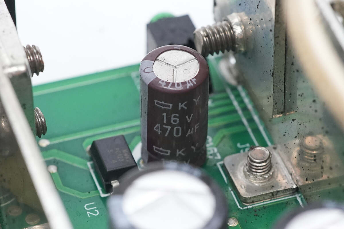
The filter capacitor is rated at 16V 470μF.
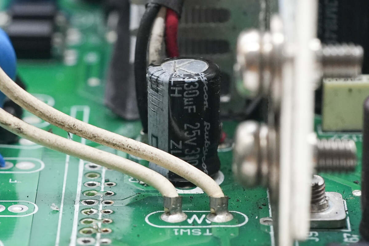
The filter capacitor is rated at 25V 330μF.
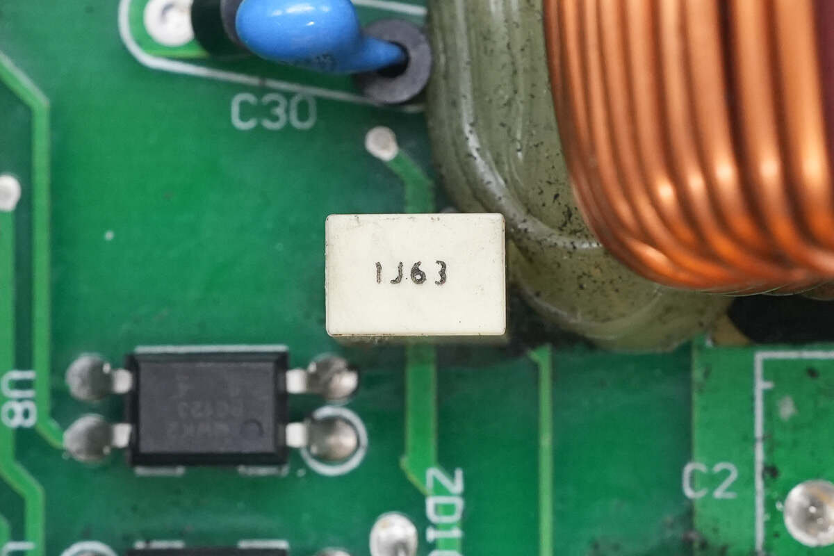
The film capacitor is rated at 1μF 63V.

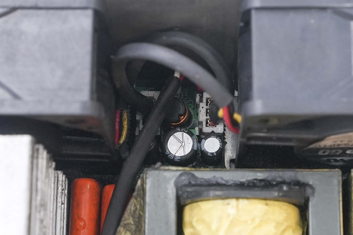
The power supply wires for the cooling fan are connected by soldering.
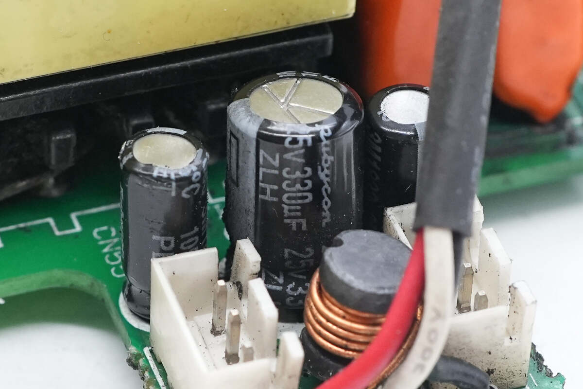
The filter capacitor is rated at 25V 330μF.
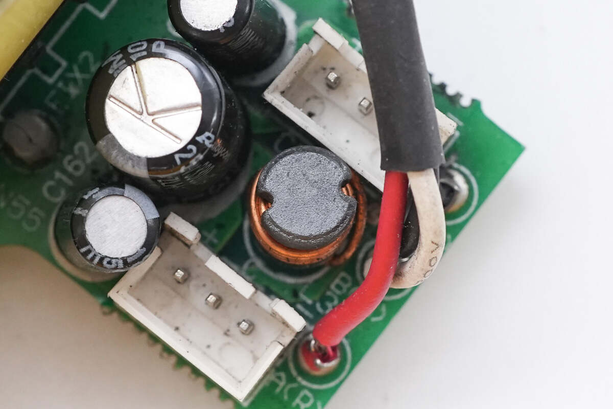
The filter inductor is wound with enameled wire.
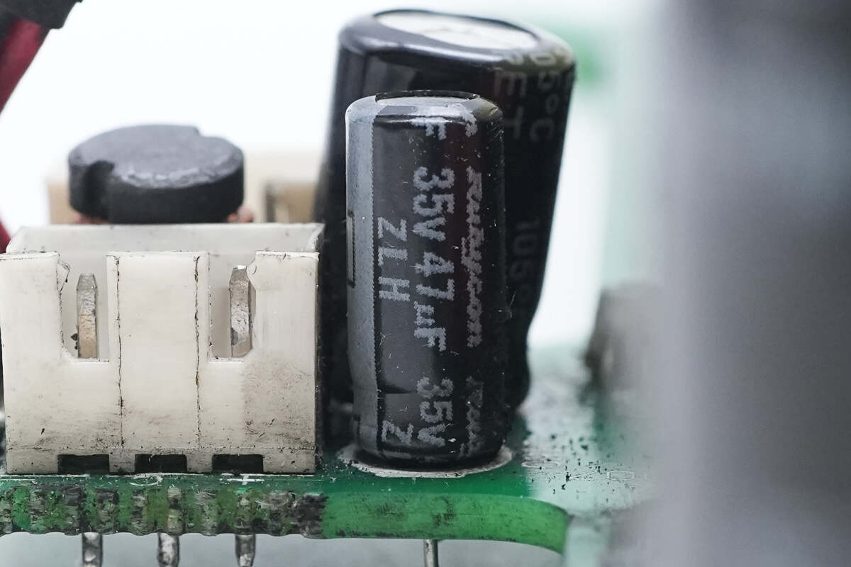
The filter capacitor is rated at 35V 47μF.

The other filter capacitor has the same specification.

The cooling fans are connected via connectors.
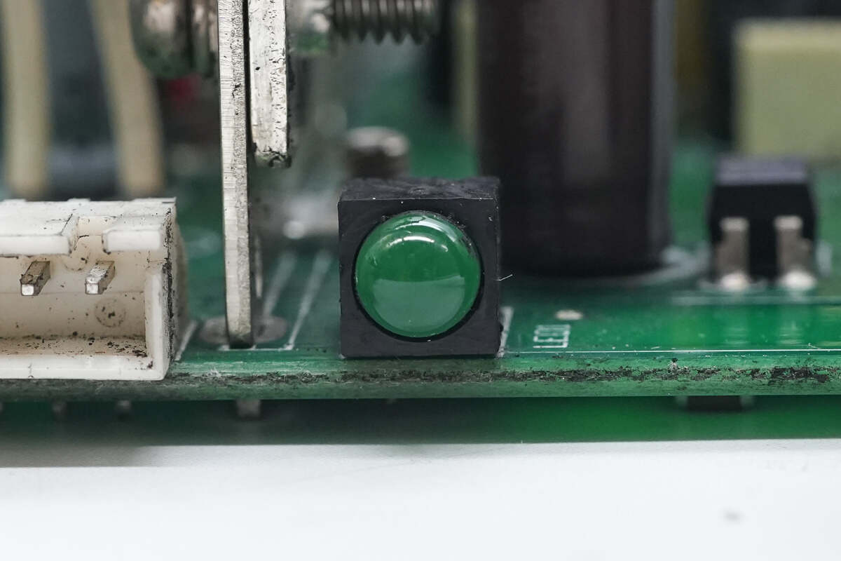
Close-up of the indicator light.
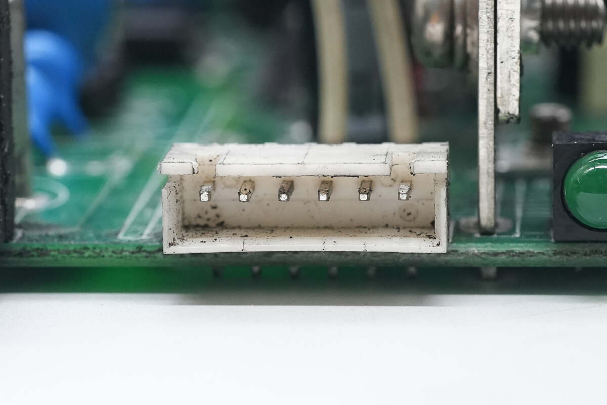
Close-up of the control terminal socket.

Well, those are all components of the MEAN WELL 1500W Switching Power Supply.
Summary of ChargerLAB

Here is the component list of the MEAN WELL 1500W Switching Power Supply for your convenience.
It features an aluminum alloy casing with built-in cooling fans. The input voltage range is 200-240V, with an output voltage of 24V and an output current of 62.5A. The rear of the power supply is equipped with AC input terminals, DC output terminal posts, and a control terminal, supporting remote control functionality.
After taking it apart, we found that it uses the Onsemi SG3525A master control chip, paired with the Texas Instruments UCC27424 driver to drive the isolation transformer. The MOSFETs are from Infineon, model IRGP20B60GP. The rectifiers are from Fuji Electric, model ESAD92-02R.
The auxiliary power chip is the PI TNY280PN, used to power the cooling fans. The heatsink for the rectifiers is equipped with a temperature switch for overheat protection. All the electrolytic capacitors are from Japanese brands, and the components are reinforced with glue for added stability. The build quality and materials are solid and reliable.
Related Articles:
1. Teardown of BricBloc 67W All-in-One Charger
2. Teardown of EcoFlow RAPID 170W 25,000mAh Power Bank with Built-in Cable (EF-HB-001)
3. Teardown of Apple iPhone Air MagSafe Battery (A3466)