Introduction
We recently acquired a 3000W server power module launched by Bel Fuse. It features a long rectangular form factor with the model number TET3000-12-069RA and incorporates a DSP controller. The module supports 100-277V AC input or 240-380V DC input, with a 12V output voltage and a maximum output current of 244A. The standby power output is also 12V, providing up to 3A. It includes a totem-pole PFC and uses GaN FETs, meeting the 80 PLUS Titanium conversion efficiency standard.
The power module supports hot-swapping and comes equipped with an I2C communication interface, utilizing the PMBus protocol for monitoring and control functions, as well as firmware updates. It includes over-temperature protection, over-voltage, and over-current protection, with LED indicators for input and output status. One end of the module features a handle and indicator lights, while the other end is equipped with a connector. Below, we will perform a teardown to examine its internal design and components.
Product Appearance
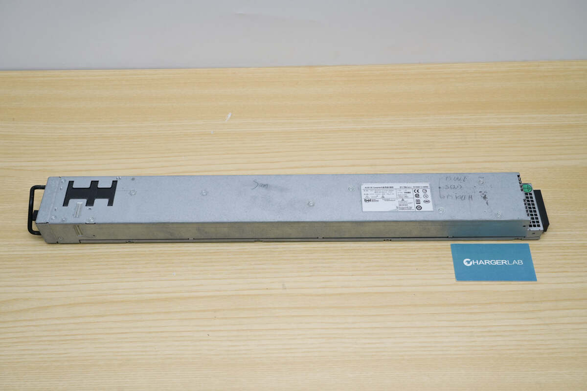
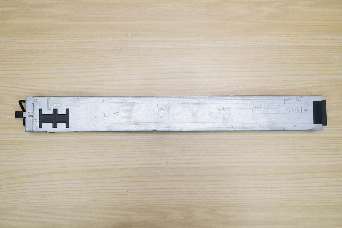
It features a rectangular form factor with an information label affixed to the front. On the left side, there is a mounting handle along with an integrated cooling fan. The right side is equipped with input and output connectors. The casing is secured with screws.
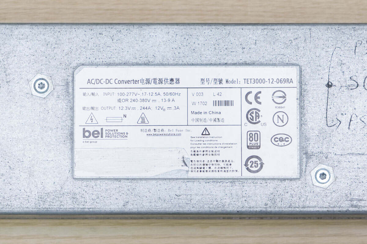
Model: TET3000-12-069RA
Input: 100-277V~, 12-12.5A, 50/60Hz or 240-380V, 13-9A
Output: 12.3V, 244A; 12Vsb 3A
Complies with 80 PLUS Titanium conversion standard
Made in China
The back casing is hollowed out in the area corresponding to the fan to reduce thickness.
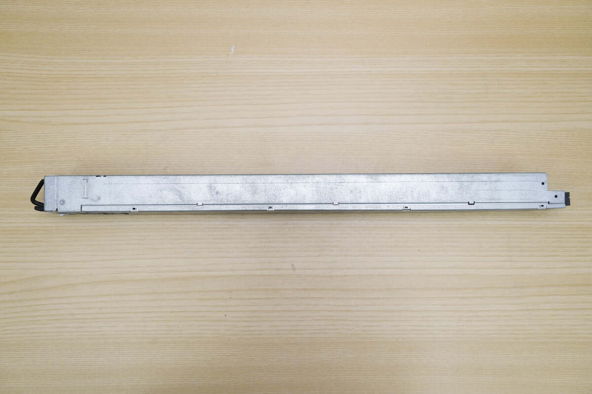
The side is secured with clips.
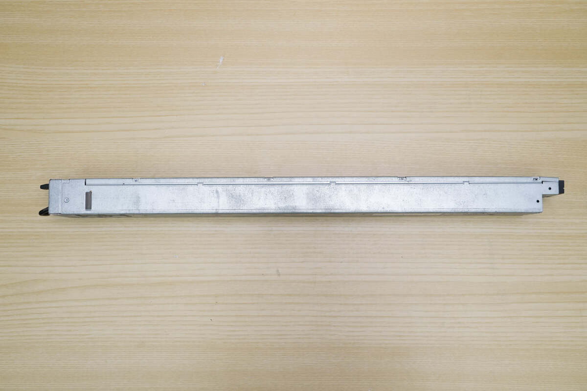
The other side is also secured with clips.
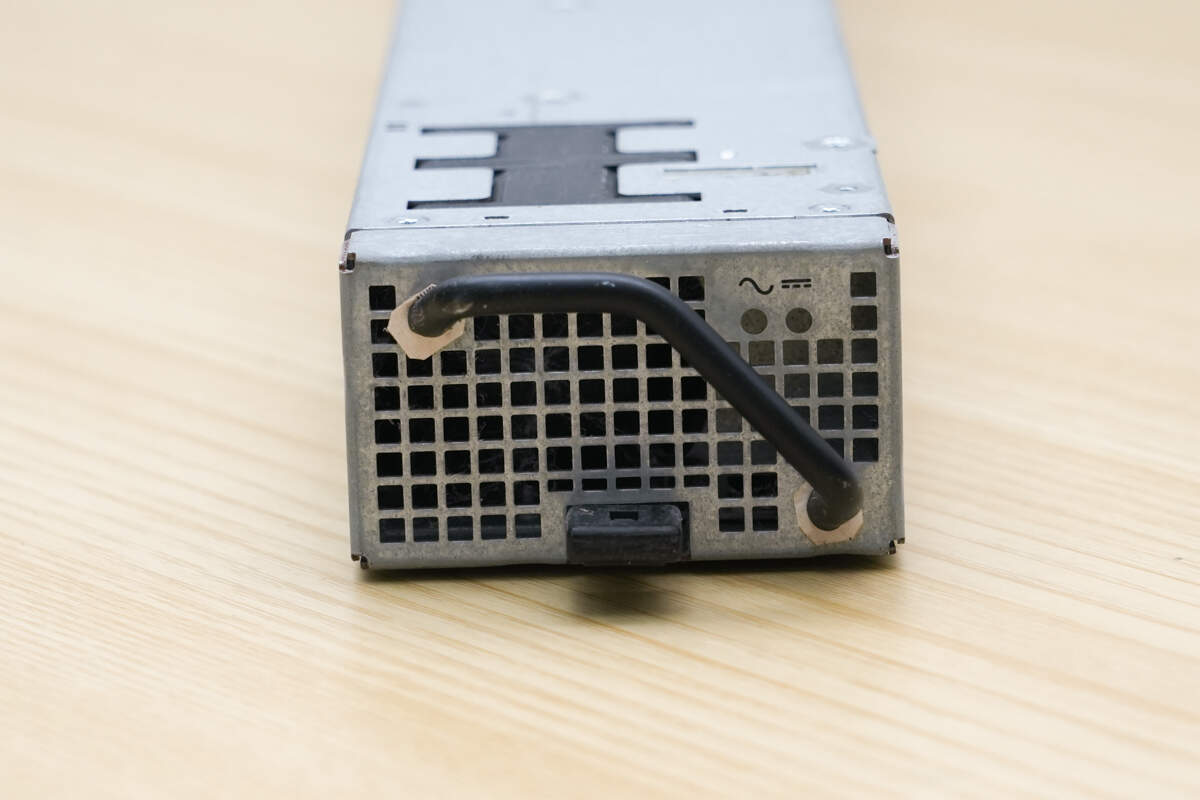
This side features numerous ventilation holes, along with a handle, indicator lights, and a breaker handle.

Close-up of the black breaker handle.
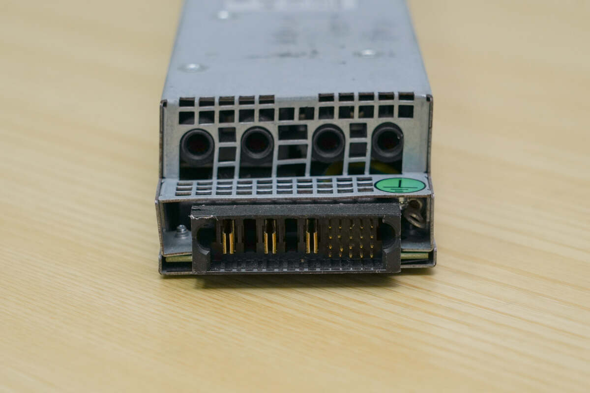
The connector on the upper side of the other panel is for the positive and negative output. The lower connector has the power input interface on the left and the communication interface on the right.
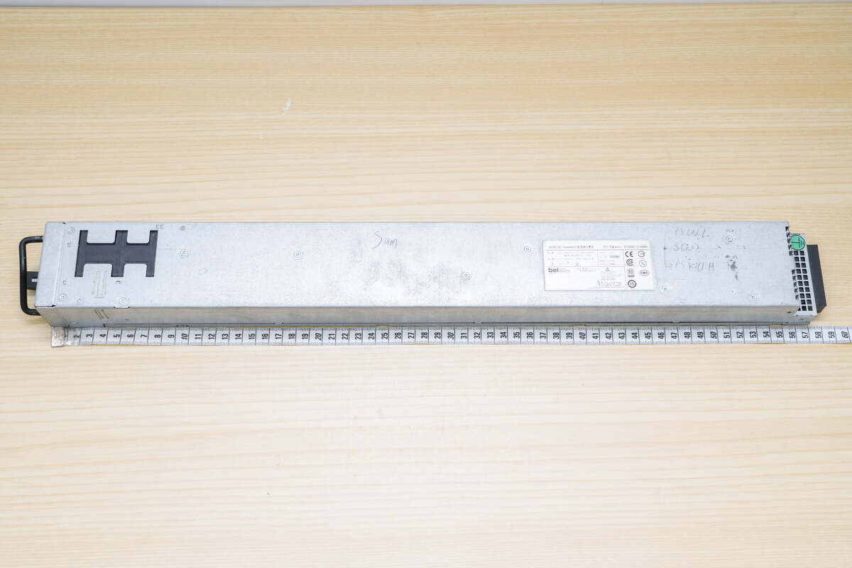
The length is about 580 mm (22.83 inches).
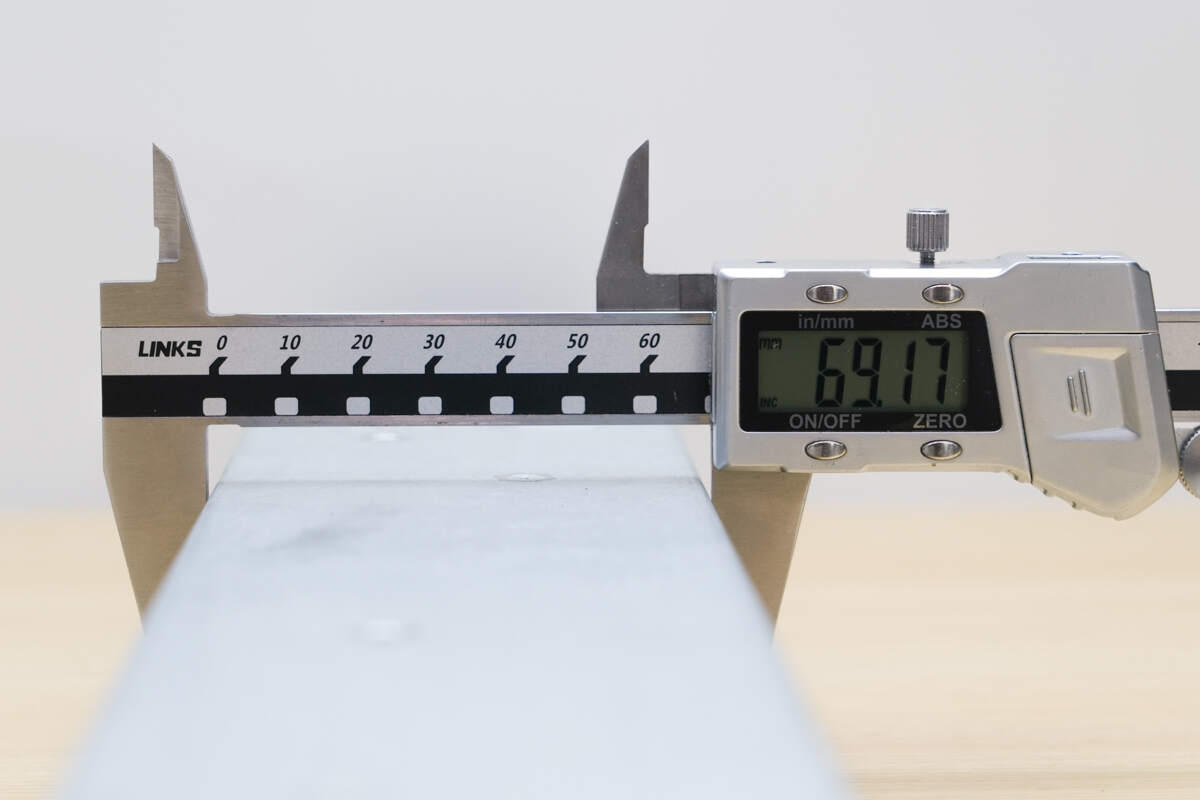
The width is about 69.2 mm (2.72 inches).
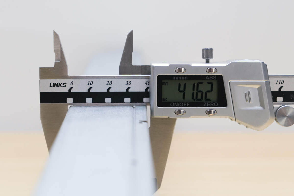
The thickness is about 41.6 mm (1.64 inches).
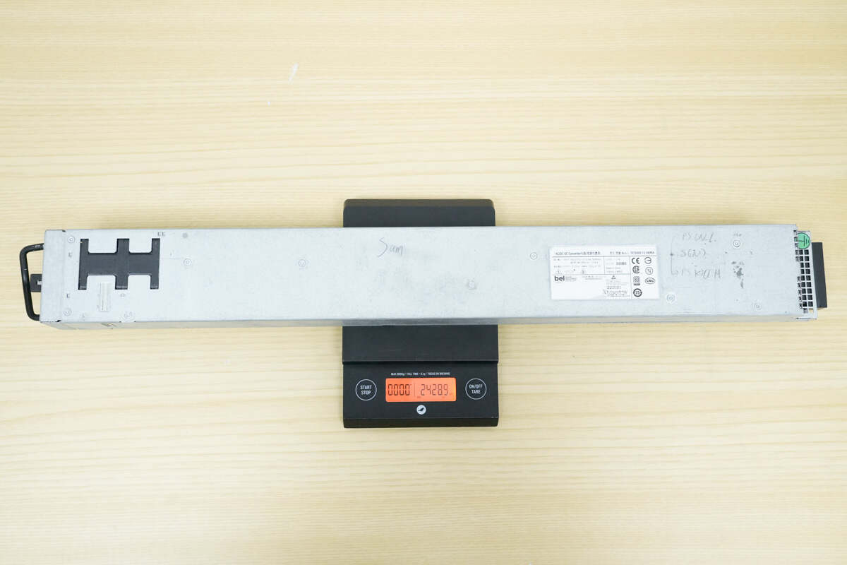
The weight is about 2429 g (85.68 oz).
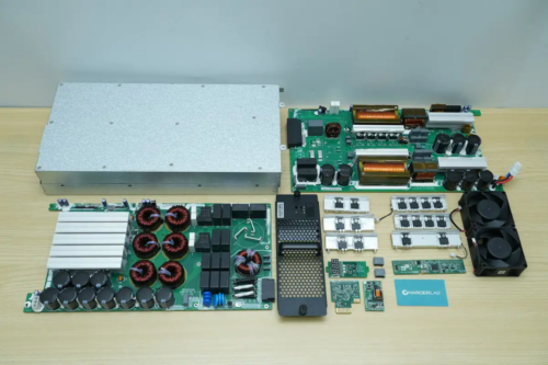
Teardown
Next, let's take it apart to see its internal components and structure.
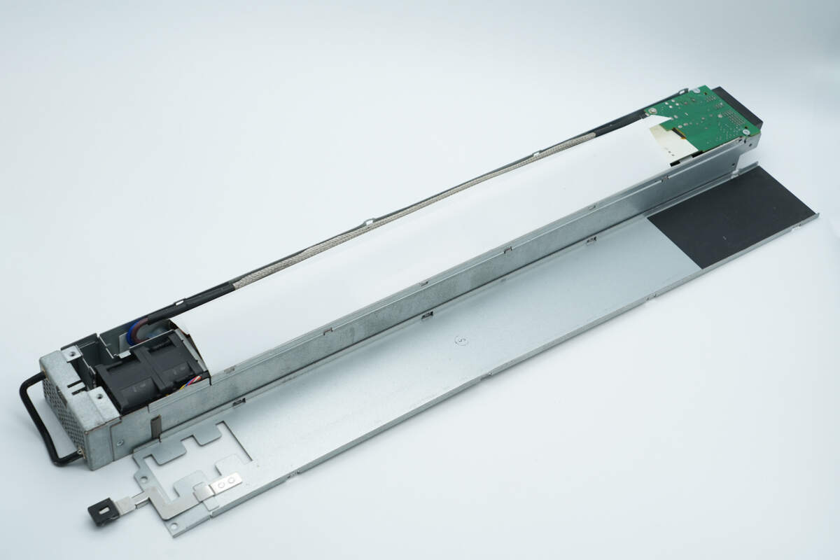
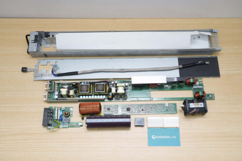
Unscrew the screws and remove the bottom cover. The casing is lined with Mylar insulation. The input cables are covered with a shielded mesh, with both ends secured using heat-shrink tubing.
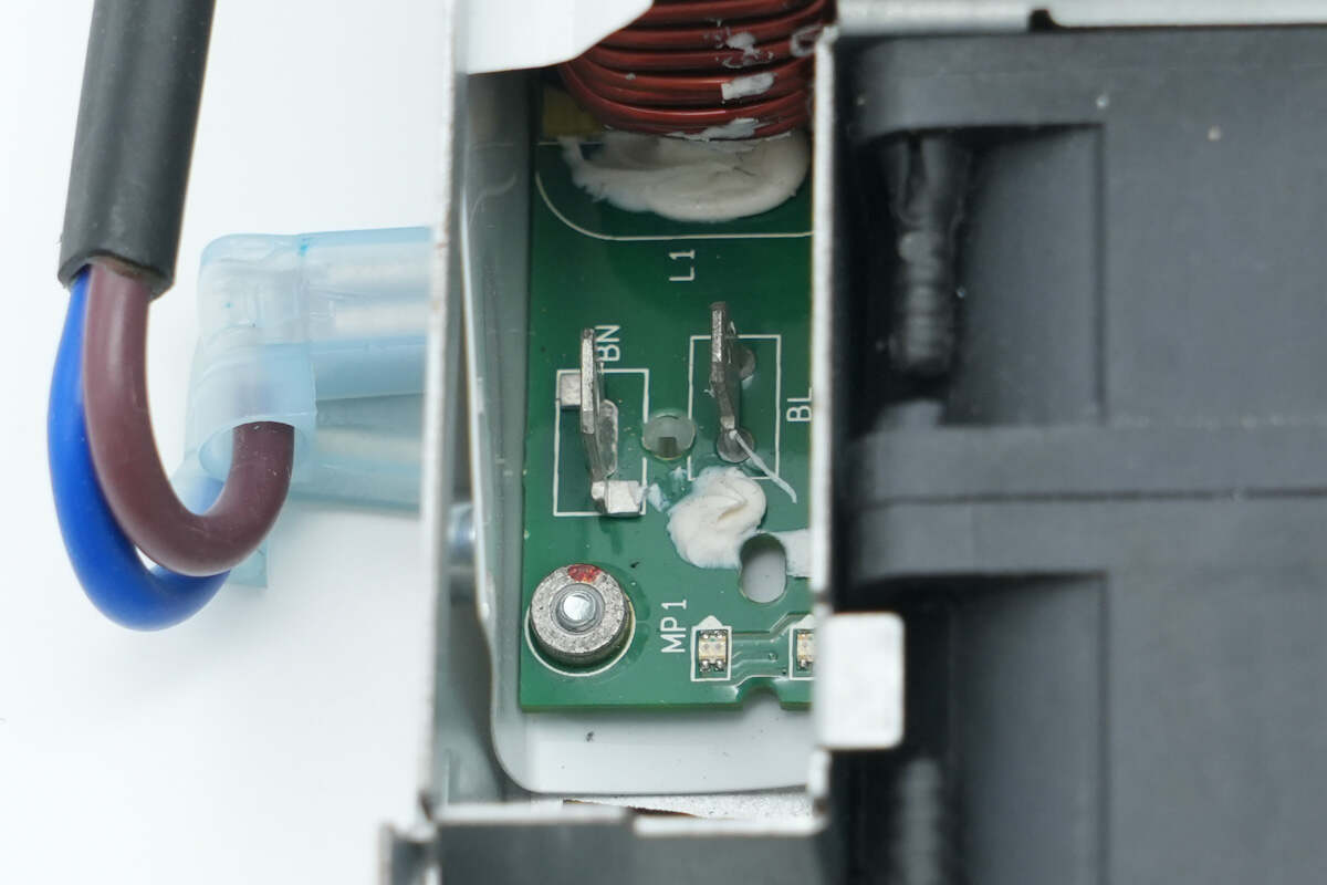
The input cables are connected through a connector.
The small PCB for the connector is secured with screws.
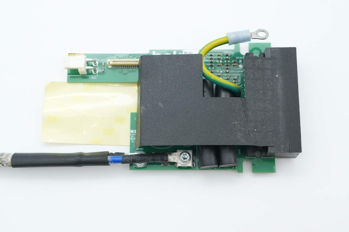
Remove the small PCB for the connector. The front is covered with Mylar insulation.
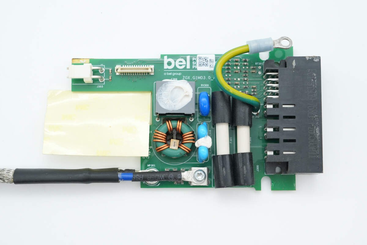
Beneath the Mylar insulation, there is a fuse, a varistor, a safety X2 capacitor, Y capacitors, and a common mode choke.
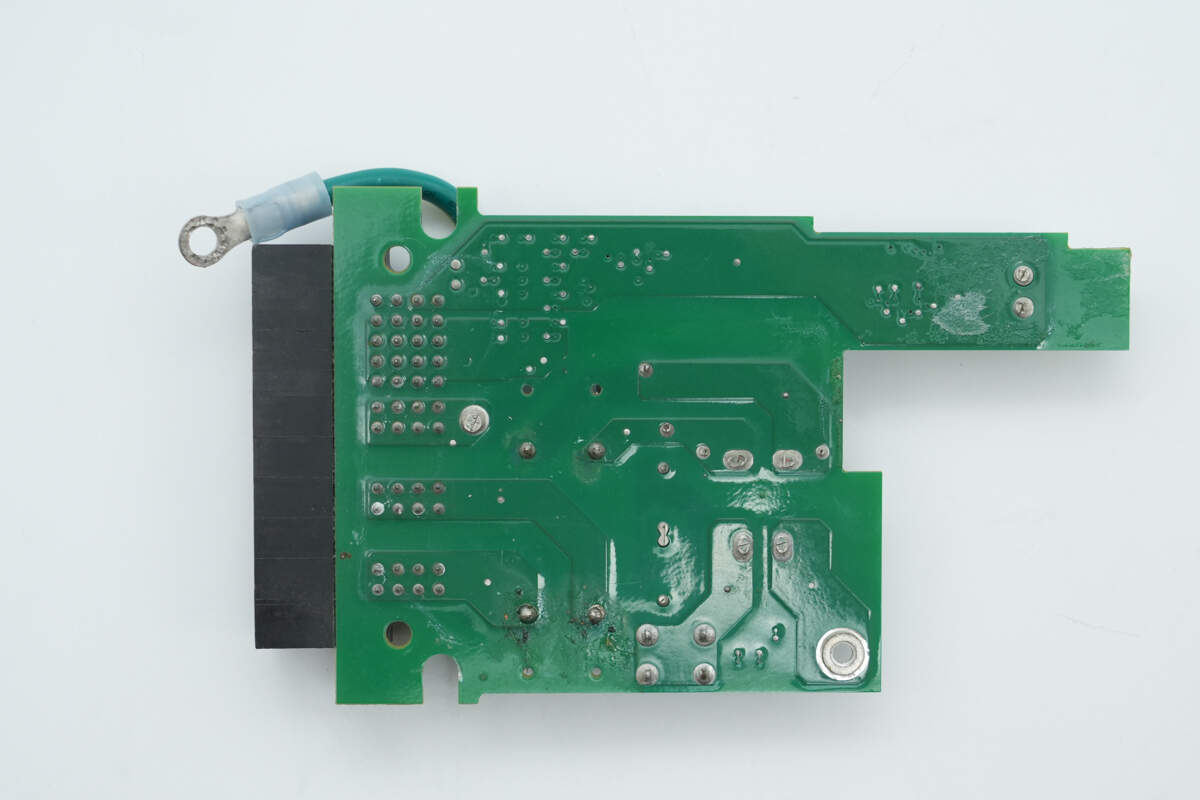
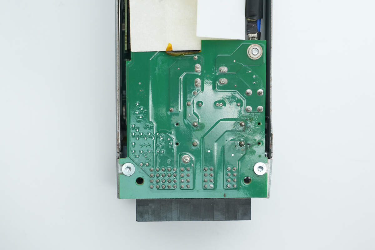
The back of the PCB has no components.
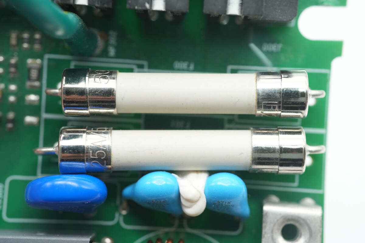
The fuses are rated at 25A, 500V each.
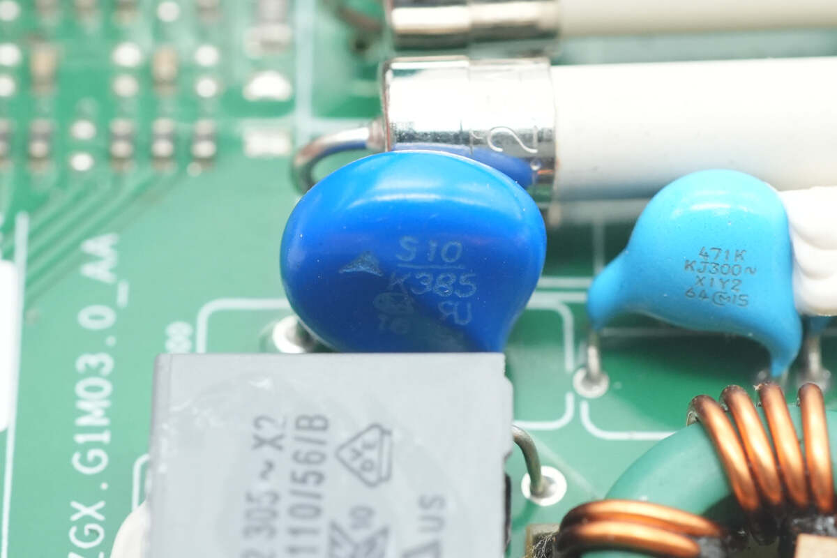
The varistor is from TDK, marked with S10K385, and is used to absorb overvoltage surges.
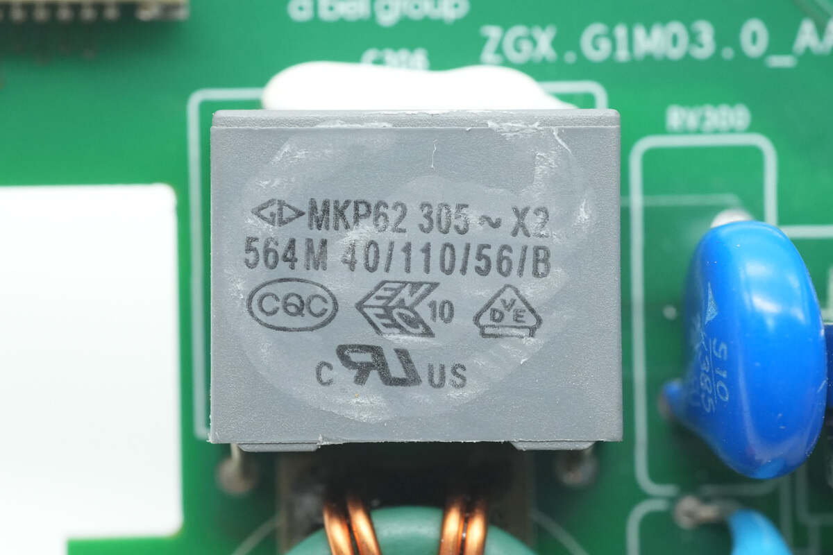
The safety X2 capacitor is from Faratronic, with a specification of 0.56μF.
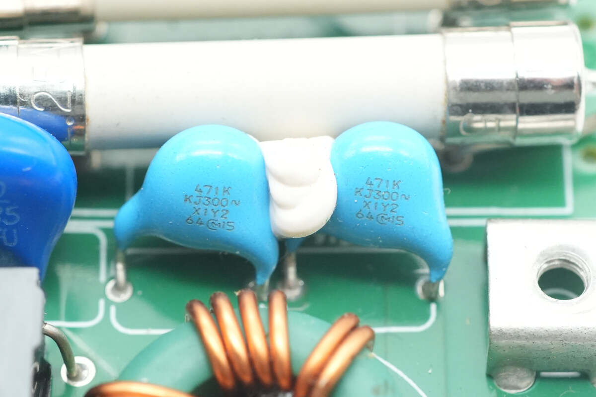
The blue Y capacitors are from MURATA.

The common mode choke is wound with enameled wire.
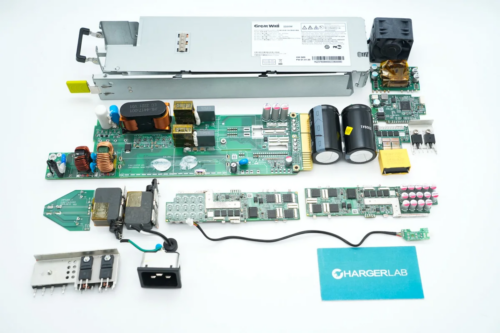
Remove the PCBA module.
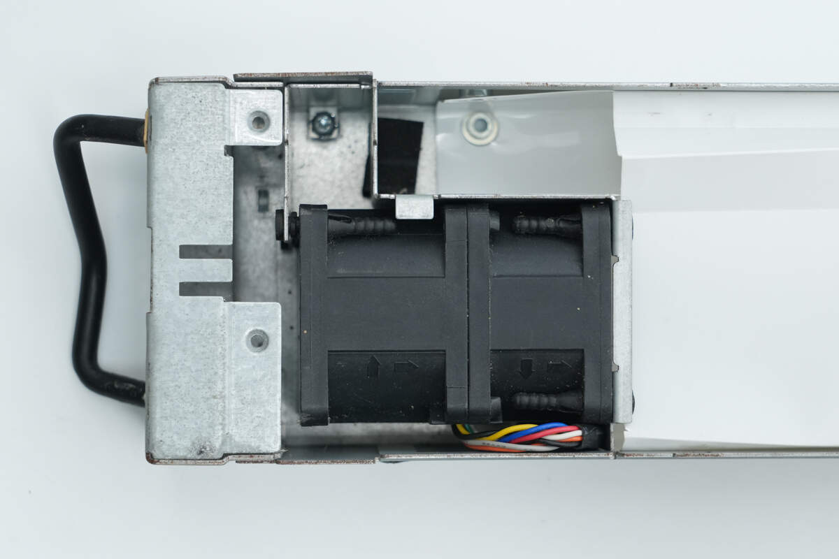
The cooling fan is secured with plastic rivets.
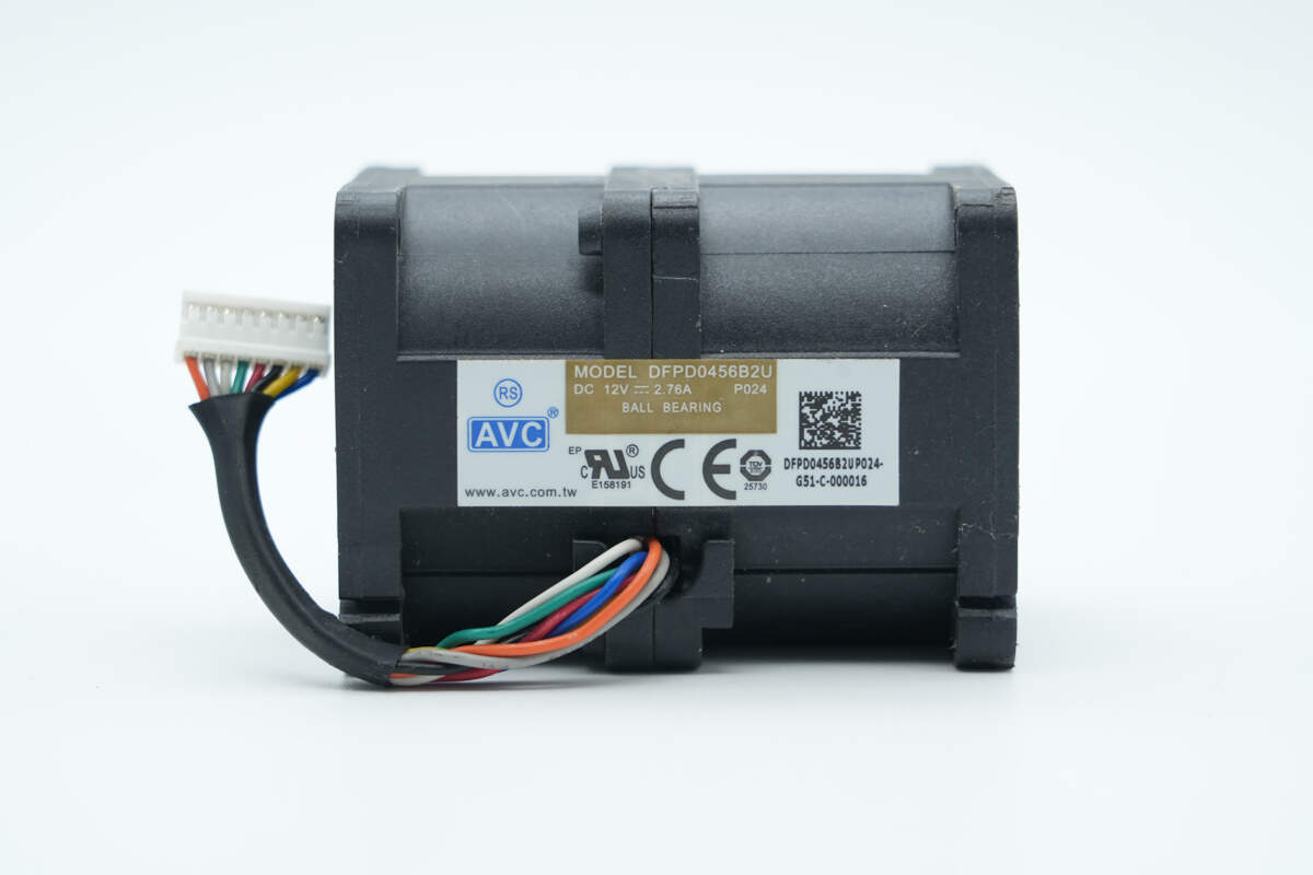
The cooling fan is from AVC, model DFPD0456B2U, with a specification of 12V, 2.76A.
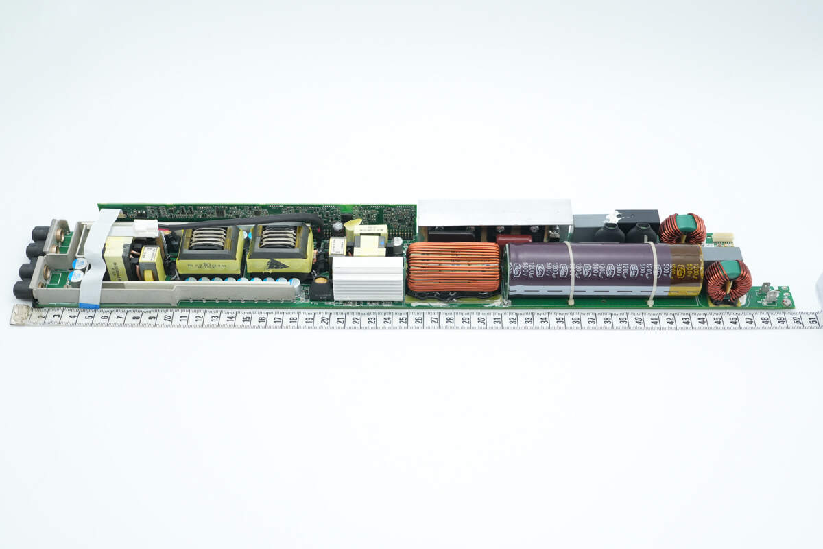
The length of the PCBA module is about 500 mm (19.69 inches).
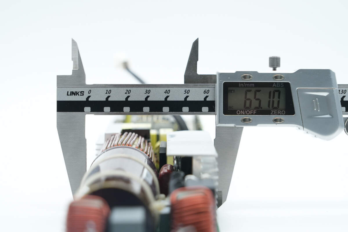
The width is about 65.1 mm (2.56 inches).

The thickness is about 36 mm (1.42 inches).
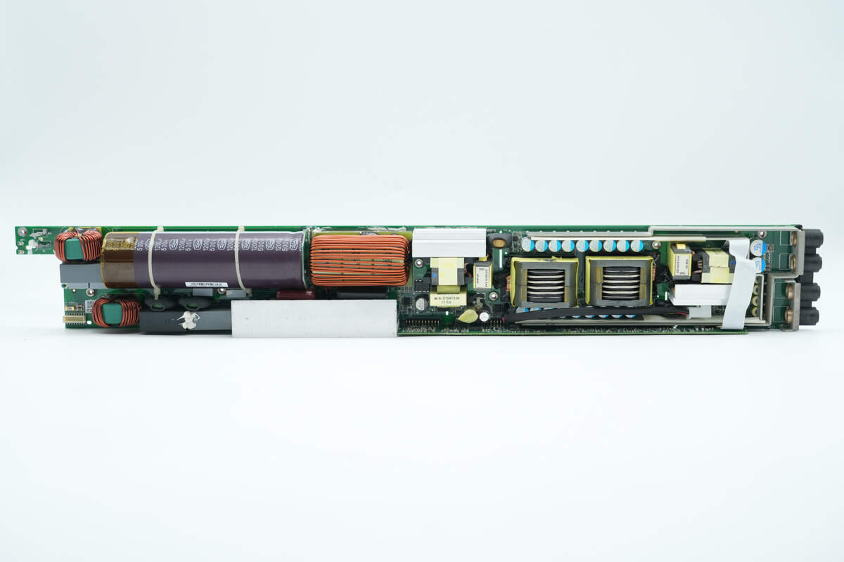
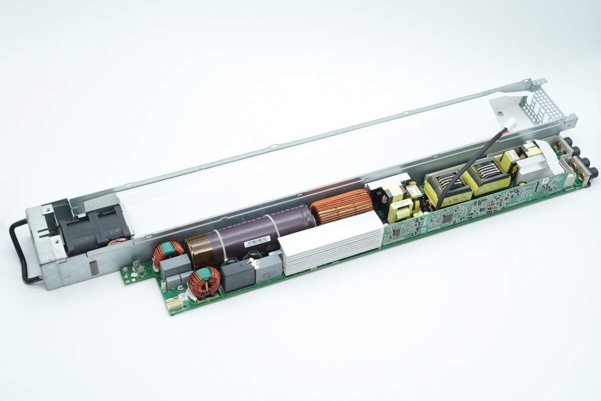
On the left side is the AC input section, which includes a common mode choke, safety X2 capacitors, a relay, film capacitors, a high-voltage filtering capacitor, and a PFC inductor.
On the right side, there are two transformers. Filter capacitors and connecting copper bars are located on the upper and lower sides of the transformers. Heat sinks are positioned on both the left and right sides of the transformers for MOSFET cooling.
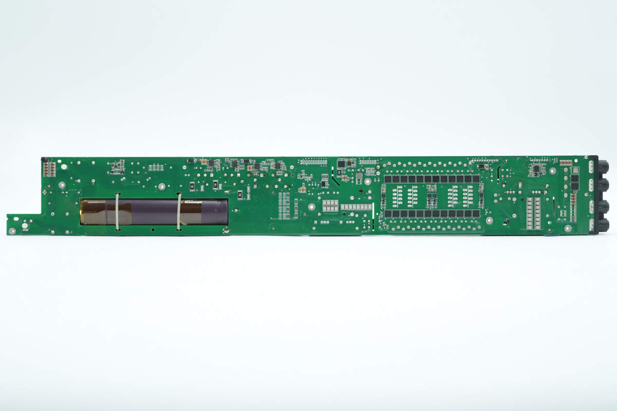
The back of the PCBA module contains isolation drivers. On the right side, there are synchronous rectifiers and drivers, resonant capacitors, op-amps, and other components.
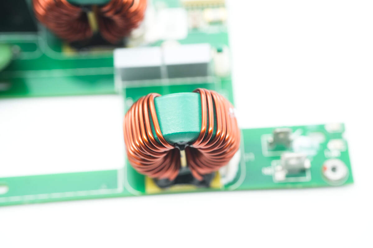
The common mode choke is wound with enameled wire, and the bottom is insulated with a Bakelite board.
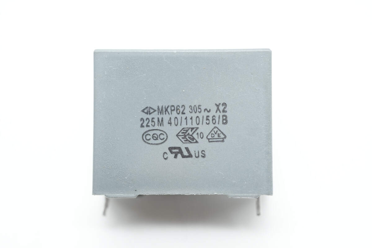
The safety X2 capacitor is from Faratronic, with a specification of 2.2μF.
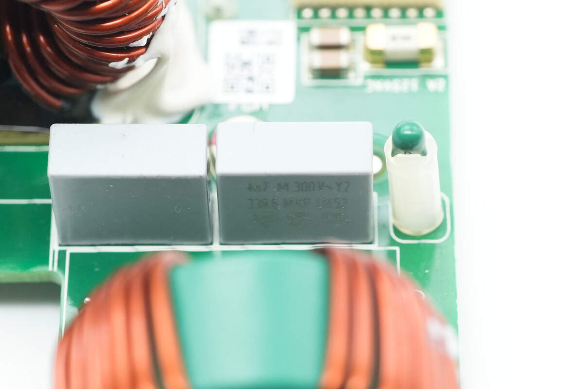
Close-up of the two film Y capacitors and a thermistor.
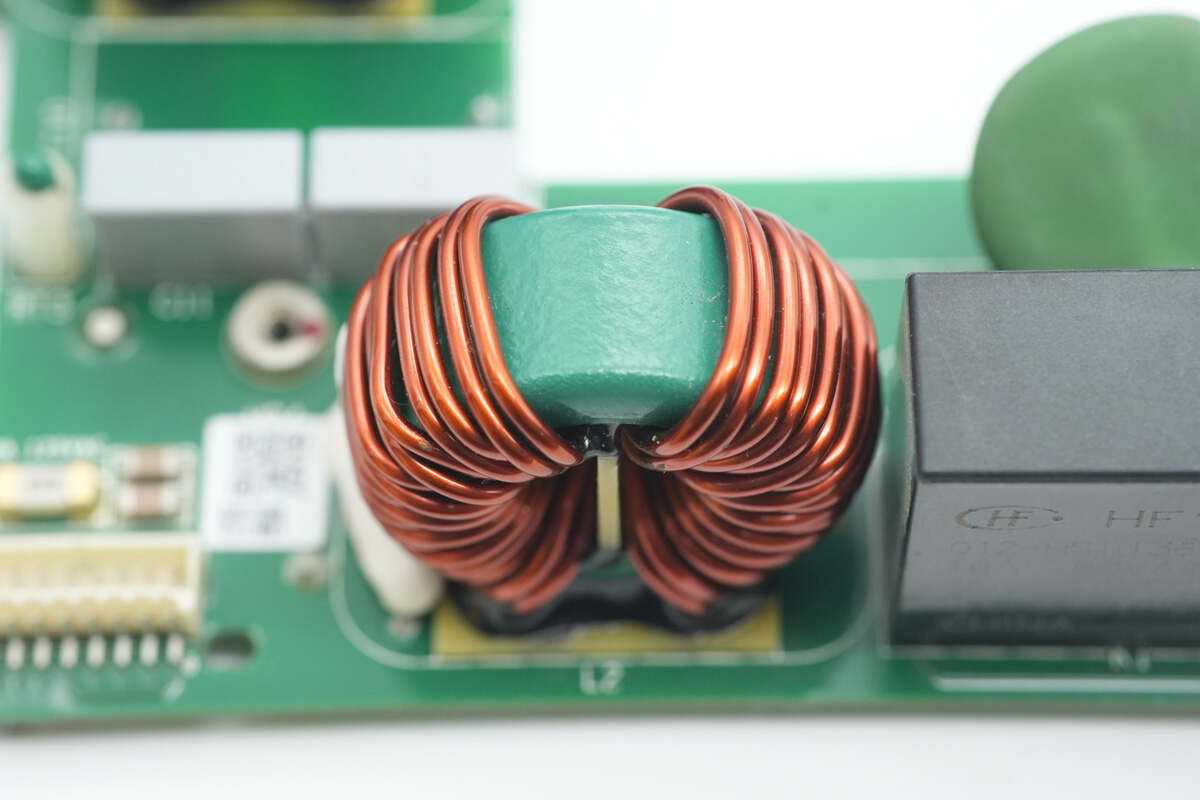
The common mode choke is wound with enameled wire, and the bottom is insulated with a Bakelite board.
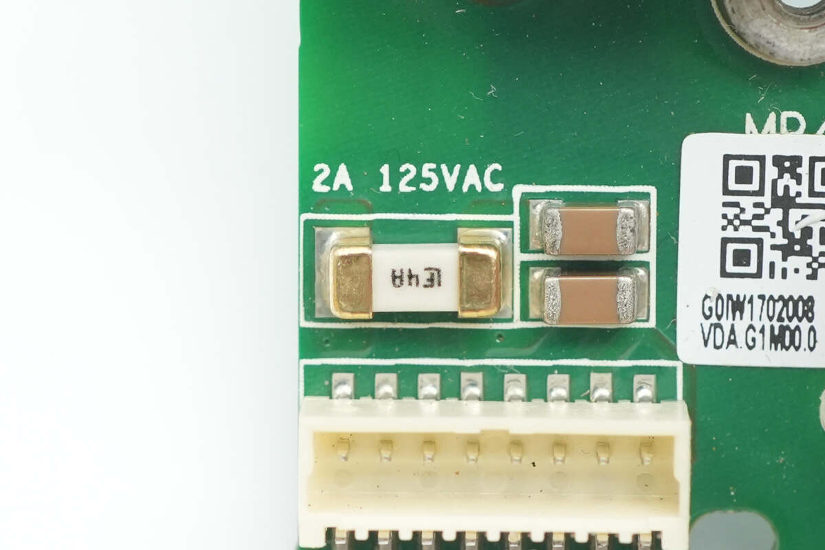
On the left side of the common mode choke, there is an SMD fuse and a connector for the cooling fan.
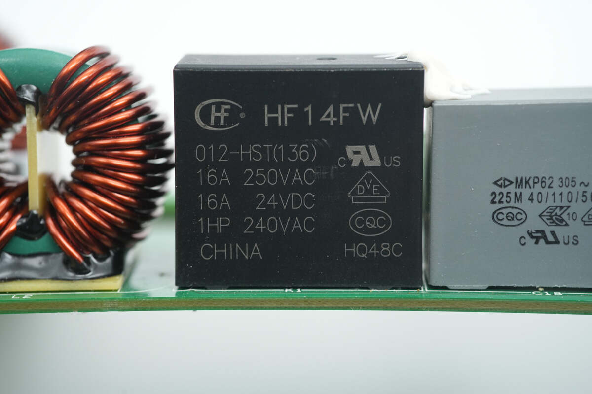
The relay is from HONGFA, model HF14FW/012-HST. It has a set of normally open contacts with a contact rating of 16A and a coil voltage of 12V.
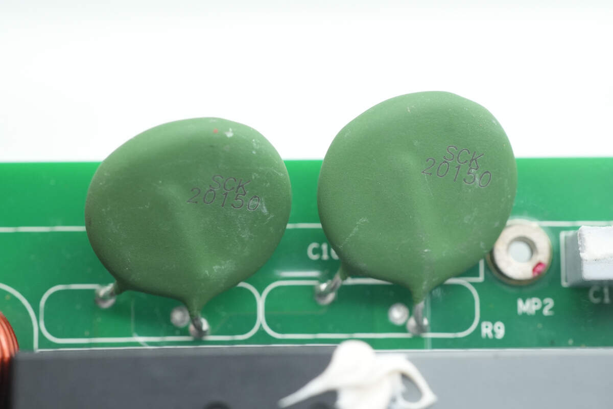
The two NTC thermistors are connected in series and are used to suppress inrush current during power-up.
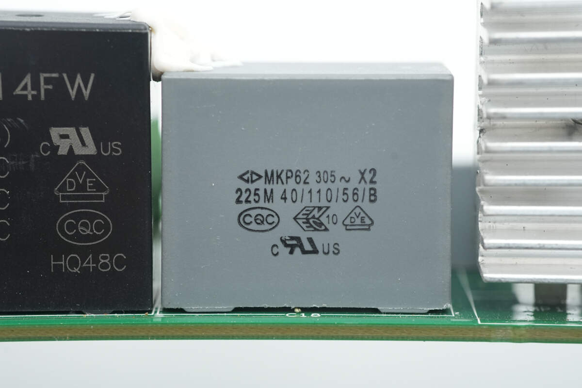
The safety X2 capacitor has a specification of 2.2μF.
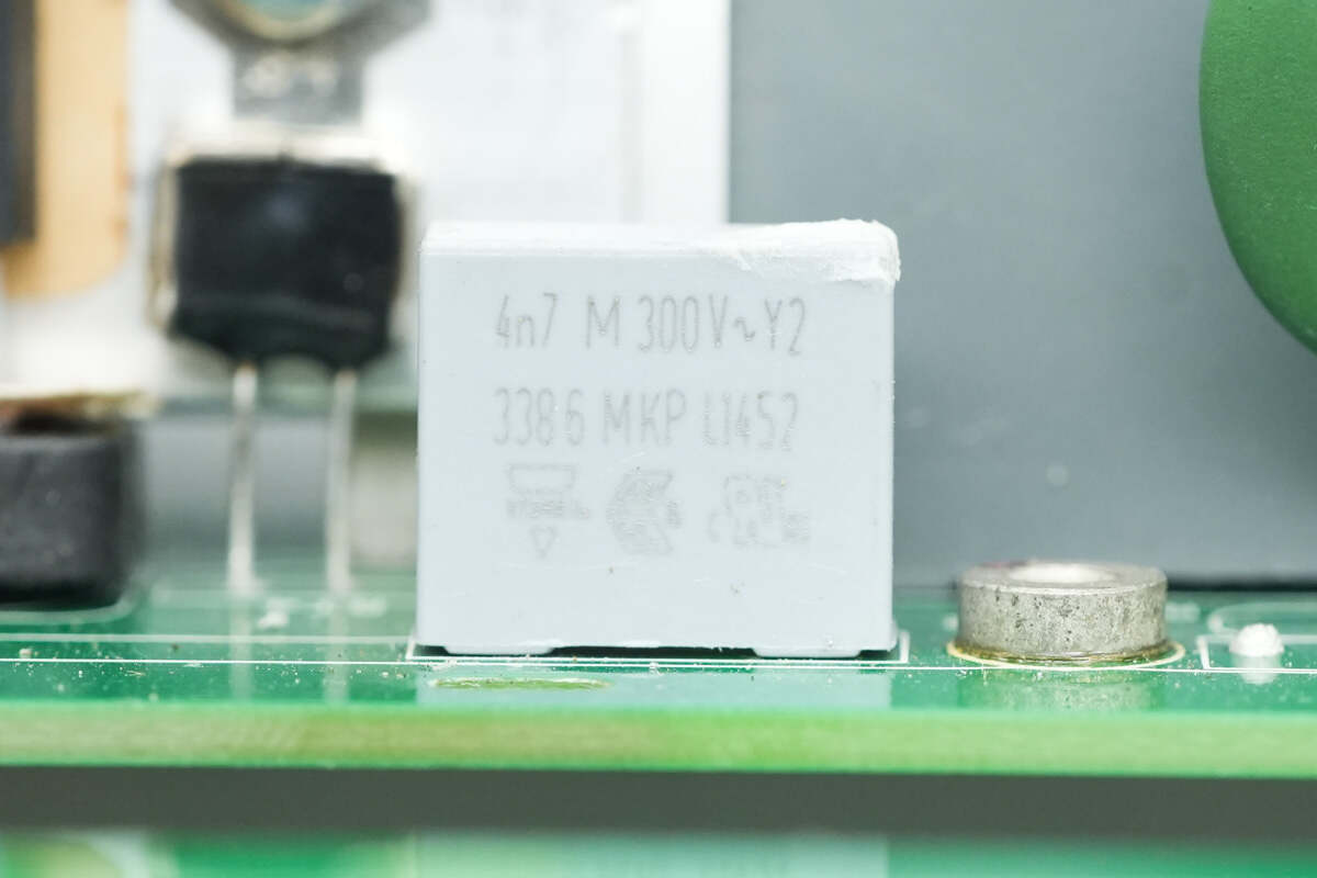
Close-up of the film Y capacitor.
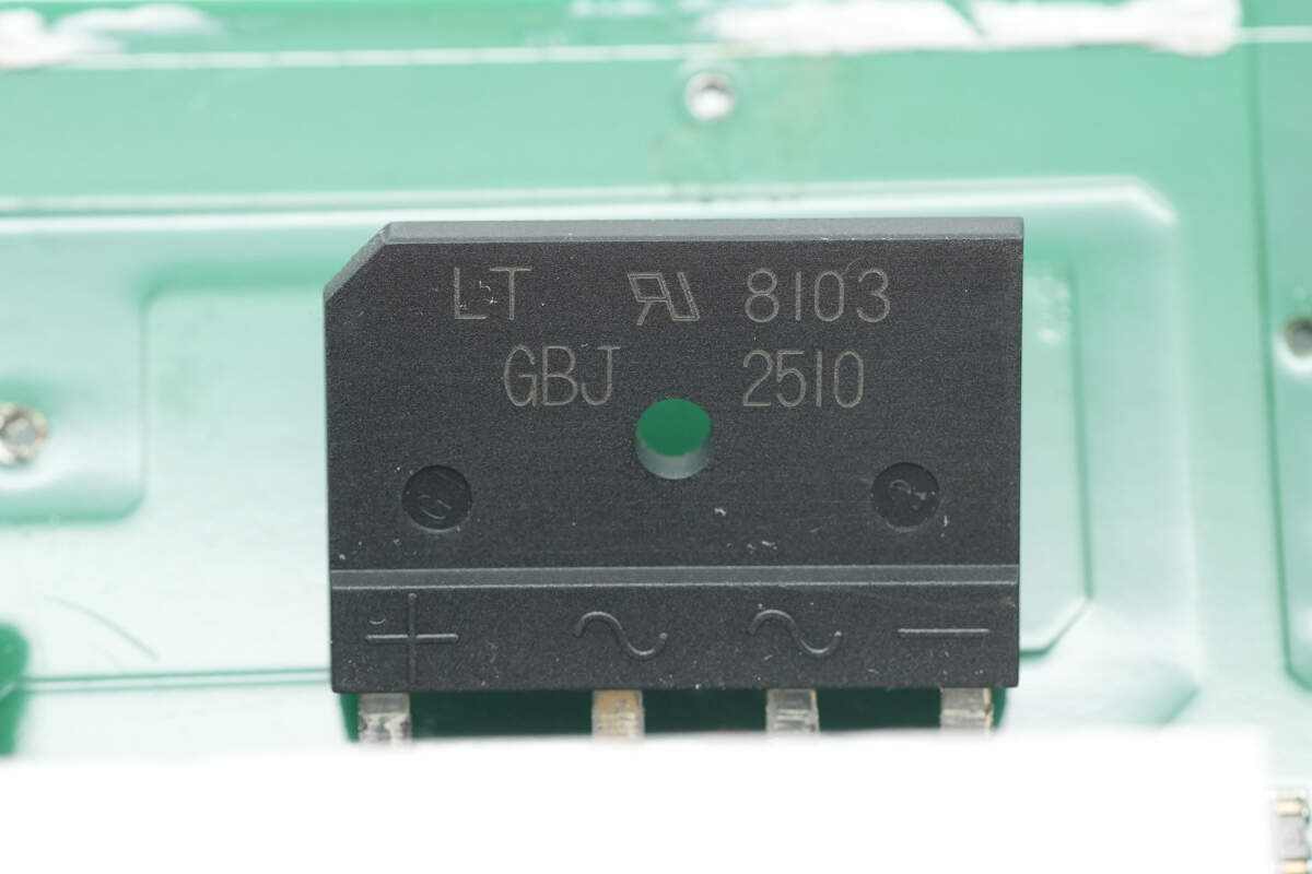
The bridge rectifier is from LITEON, model GBJ2510, with a specification of 1000V, 25A, and is packaged in a GBJ format.
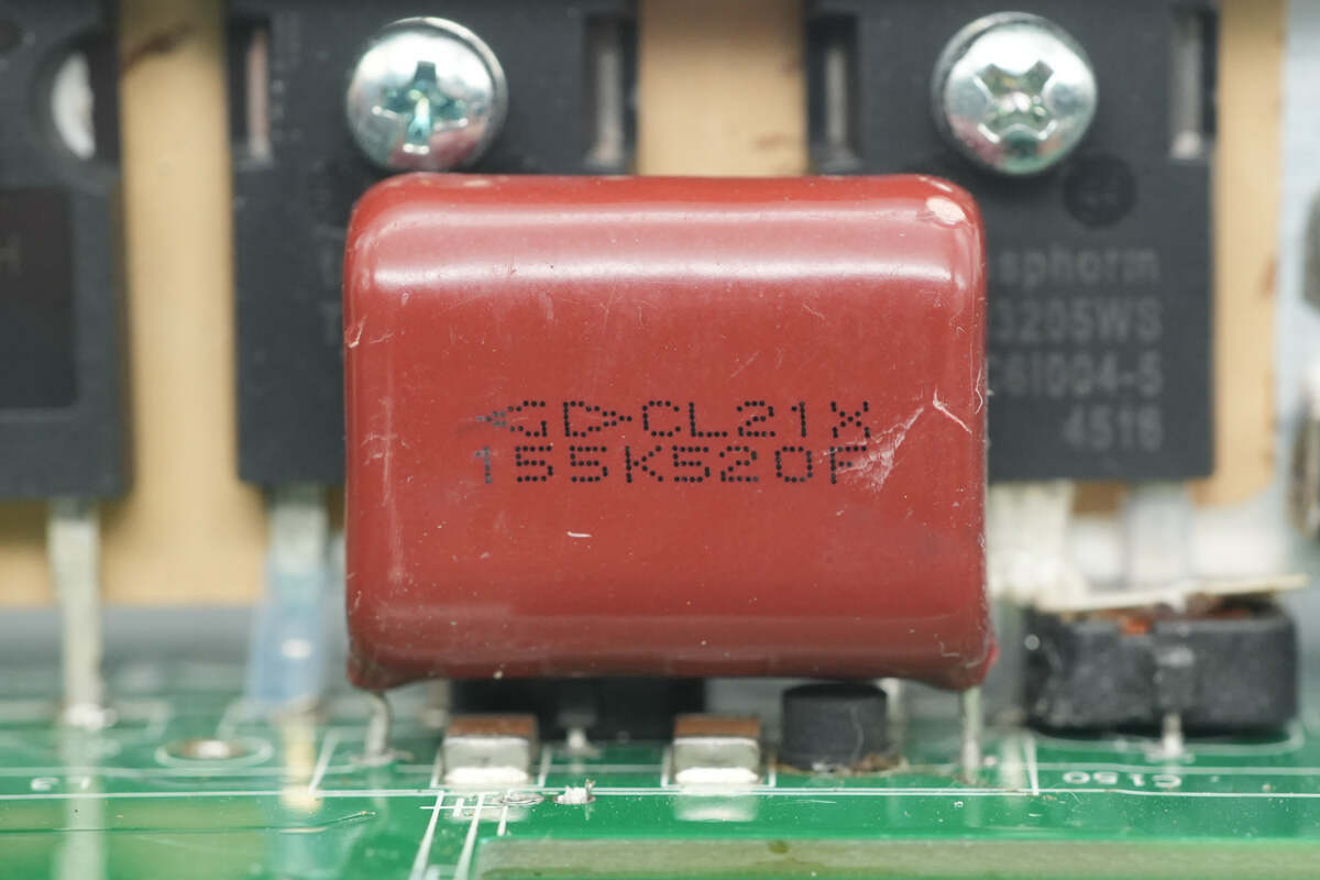
The film filtering capacitor is from Faratronic, with a specification of 1.5μF, 520V.
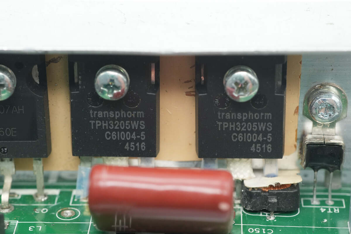
The GaN FETs are from Renesas, model TPH3205WS, with a voltage rating of 600V, a conduction resistance of 52mΩ, and are packaged in a TO-247 3L format. They are used in a totem-pole PFC fast half-bridge configuration, with current transformers on the pins.
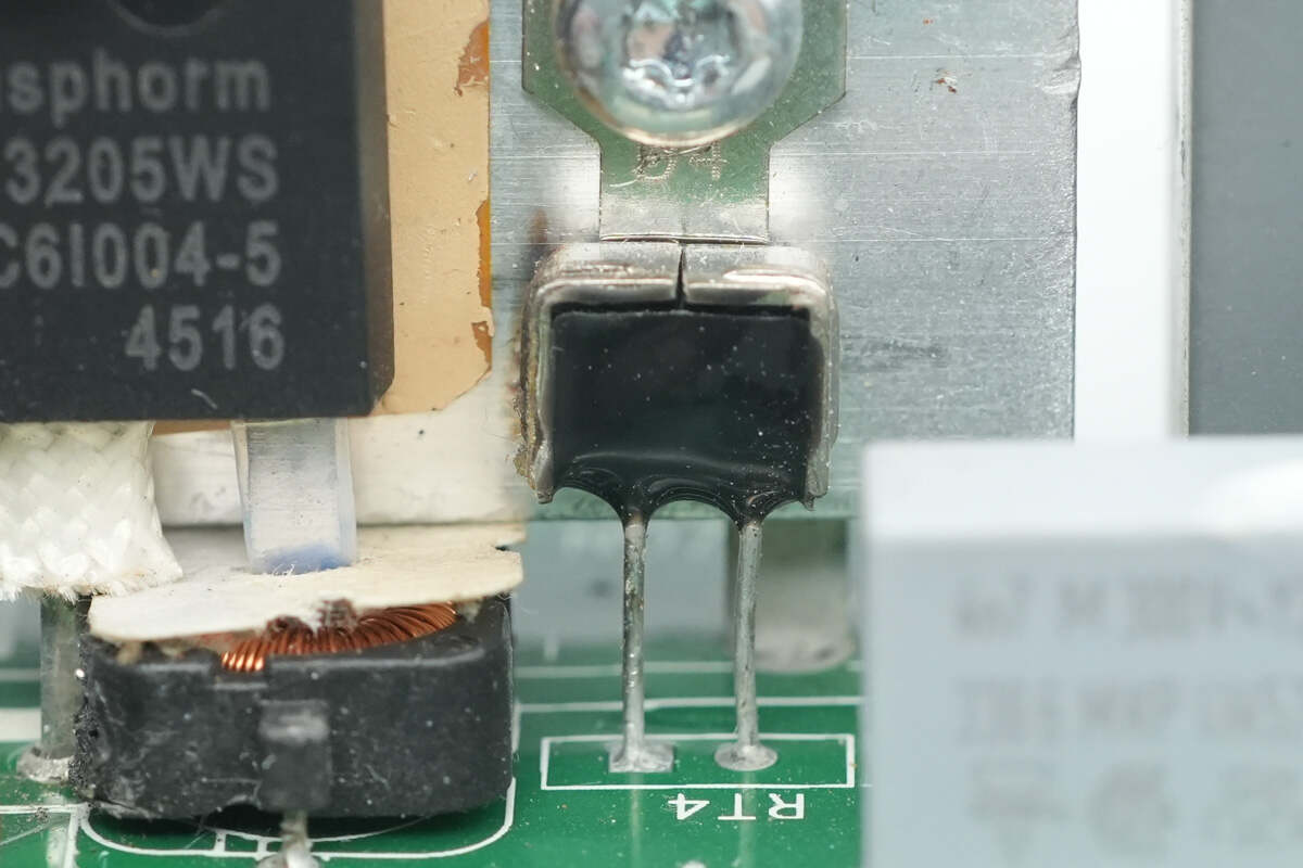
Close-up of the thermistor used for detecting the heatsink temperature.
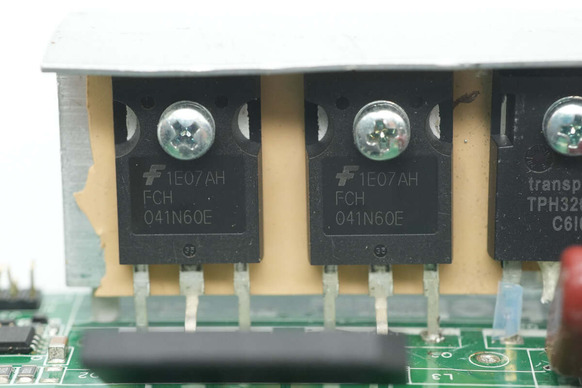
The low-speed half-bridge MOSFETs are from Onsemi, model FCH041N60E, an NMOS with a voltage rating of 600V, a conduction resistance of 41mΩ, and packaged in a TO-247 format.
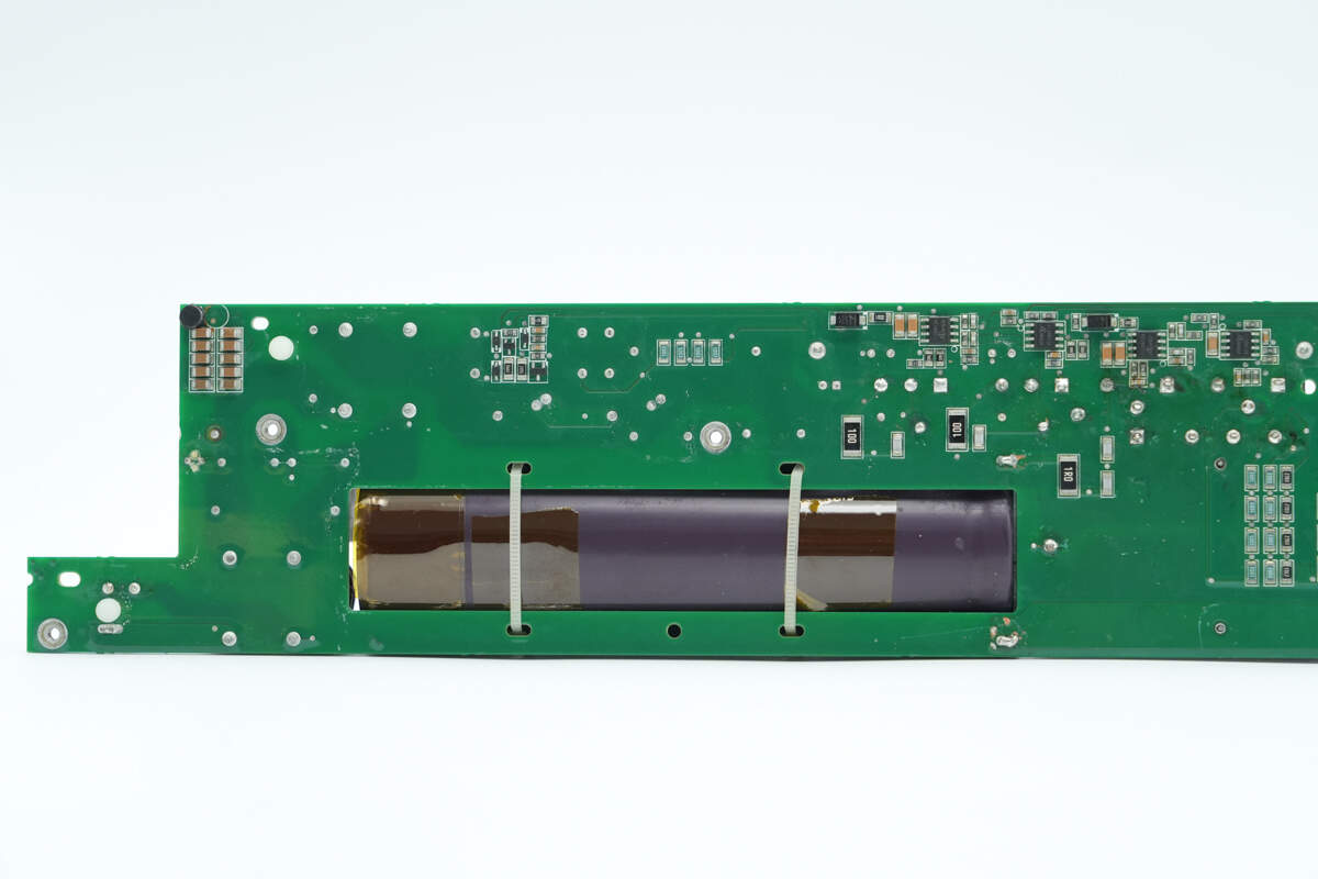
The high-voltage filtering capacitor is secured with zip ties.
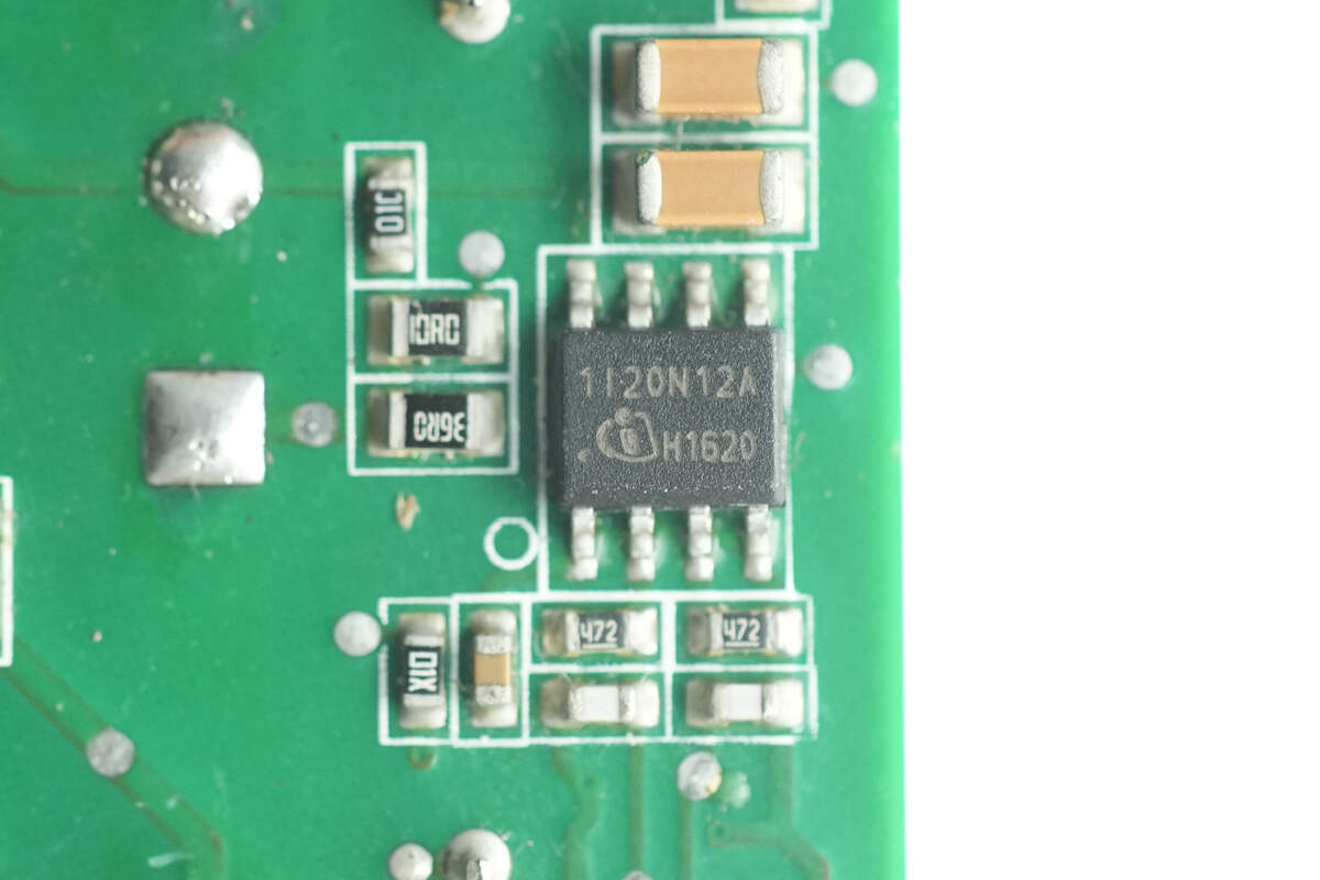
The driver for the totem-pole PFC MOSFETs is from Infineon, marked with 1I20N12A, model 1EDI20N12AF. It is a single-channel isolated gate driver that supports IGBTs, MOSFETs, and SiC MOSFETs with voltage ratings of 600/650/1200V. The driver features a peak current of 10A and a rail-to-rail output, packaged in a DSO-8 format. Four of these drivers are used, corresponding to the four MOSFETs.
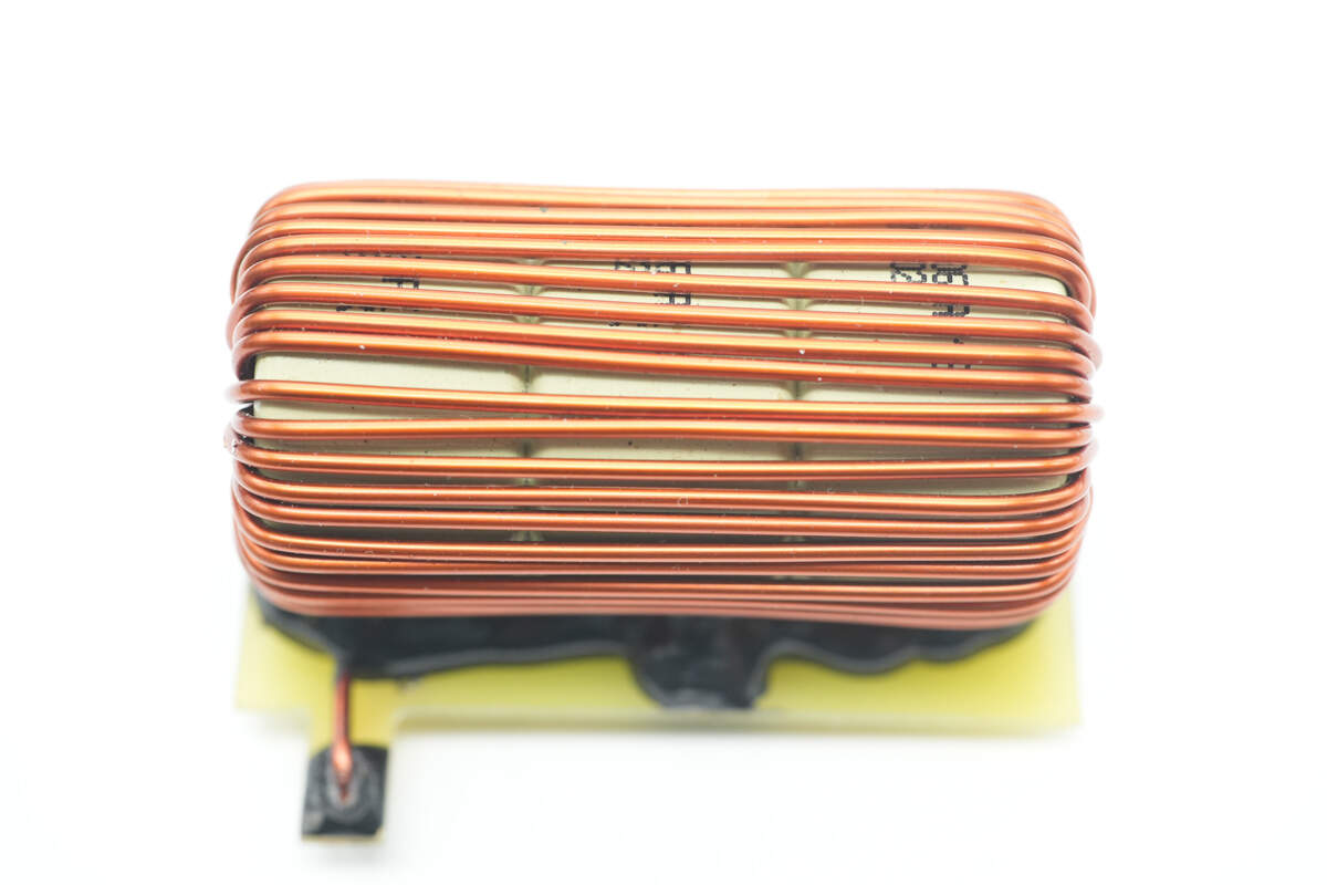
The PFC boost inductor is wound with enameled wire, and the bottom is insulated with a Bakelite board.
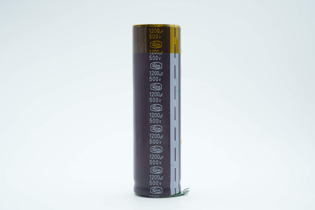
The high-voltage filtering capacitor is from Lelon, with a specification of 1200μF, 500V.
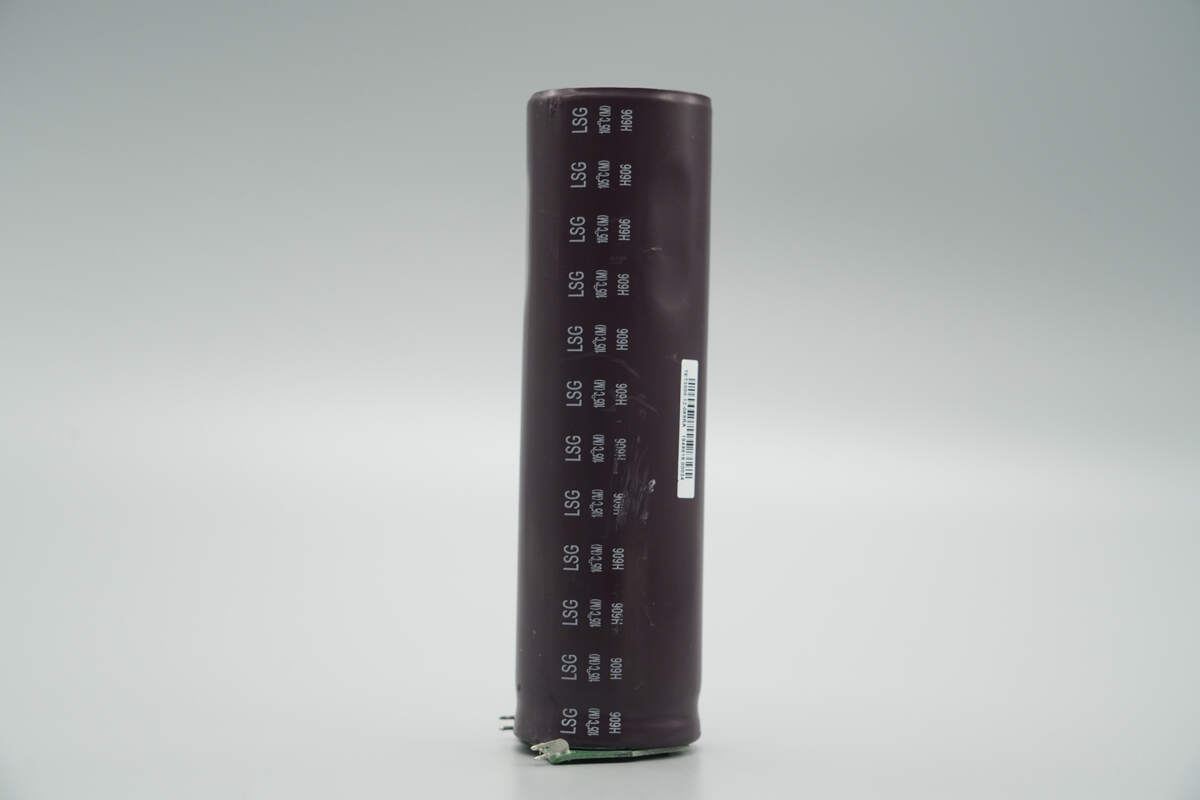
The capacitor is from the LSG series, rated for an operating temperature of 105 °C, and comes with a 2000-hour lifespan guarantee.
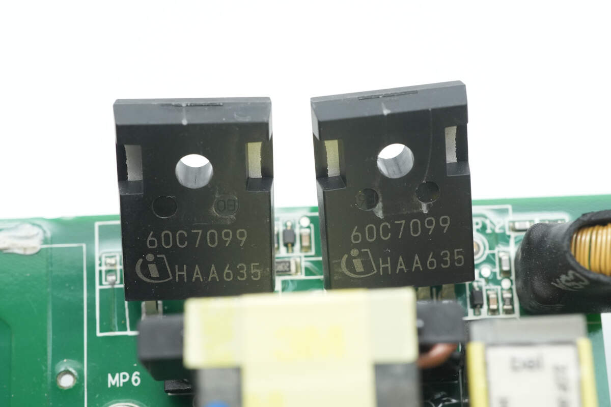
The LLC MOSFETs are from Infineon, marked with 60C7099, model IPZ60R099C7. They are part of the CoolMOS C7 series, NMOS, with a voltage rating of 650V, a conduction resistance of 99mΩ, and are packaged in a TO-247-4 format.
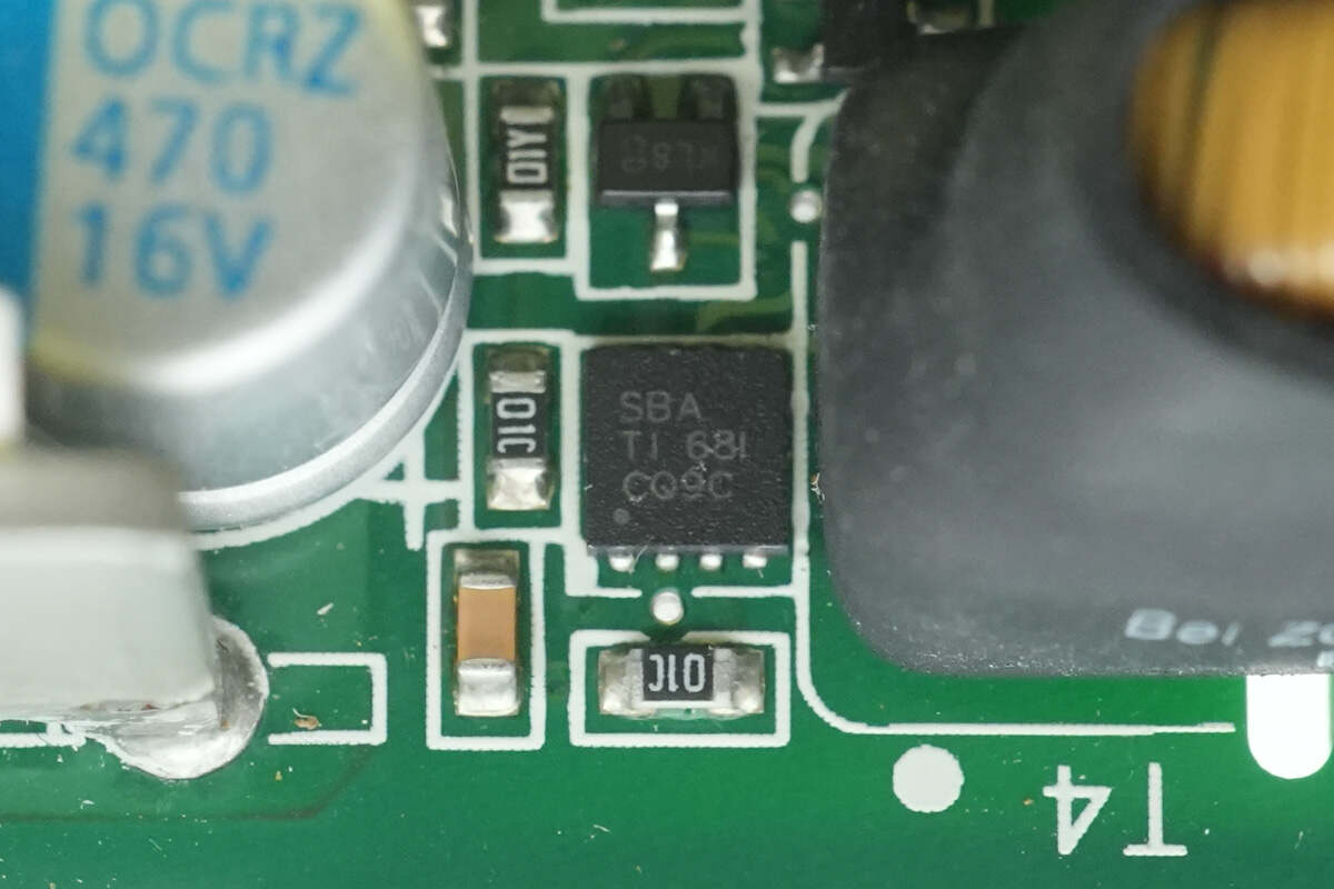
The driver is from Texas Instruments, marked with SBA, model UCC27524. It is a dual-channel 5V high-speed low-side gate driver with the capability of negative input voltage, packaged in a WSON8 format.
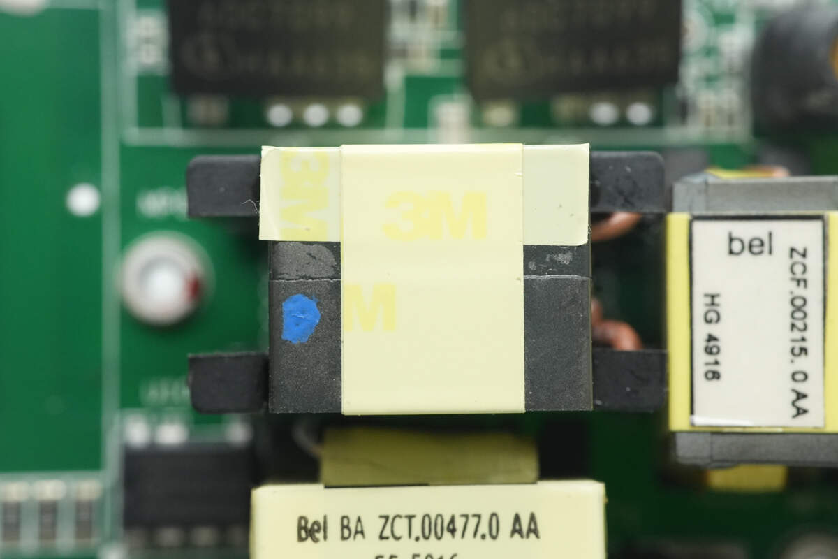
The isolation transformer is wound with insulated wire and coated with heat-shrink tubing for insulation. It is used to drive the LLC MOSFETs.
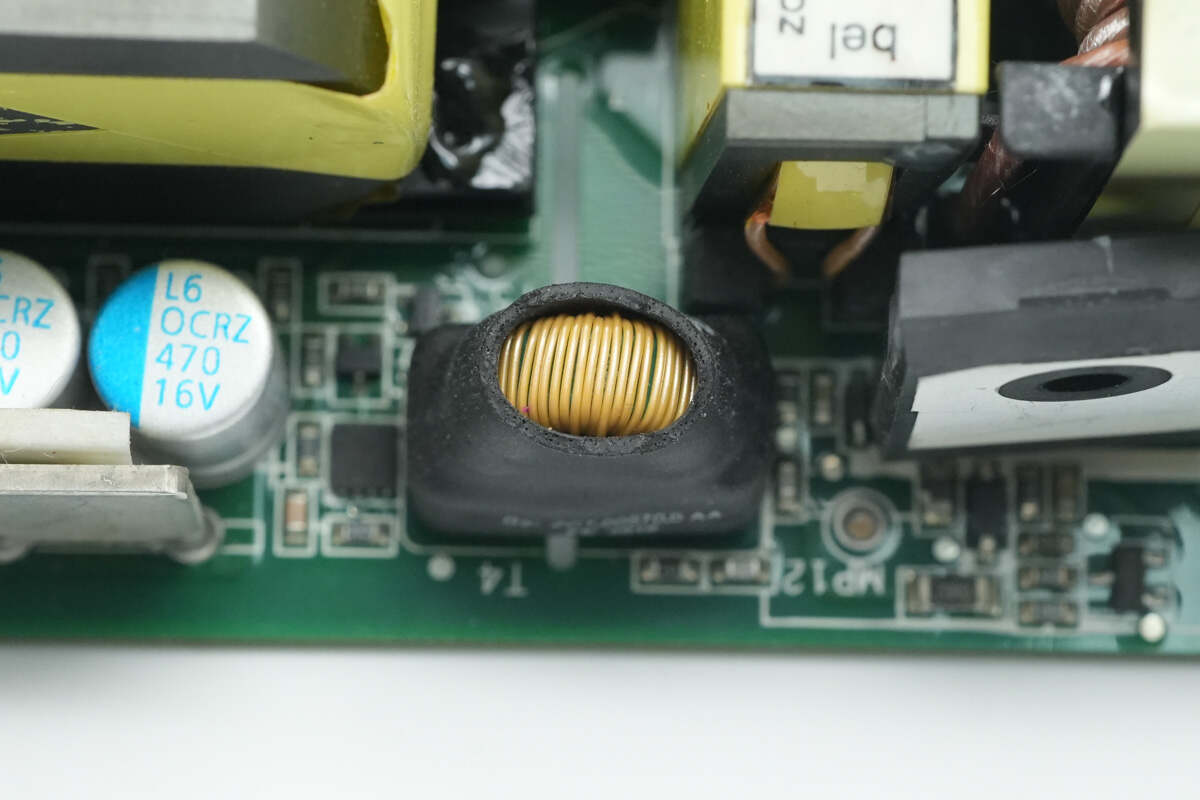
The resonant inductor is wound with Litz wire.
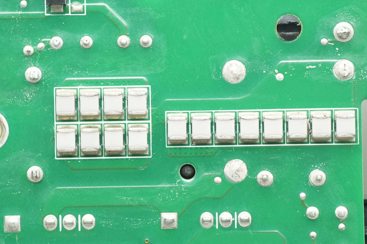
Close-up of the NPO resonant capacitors.
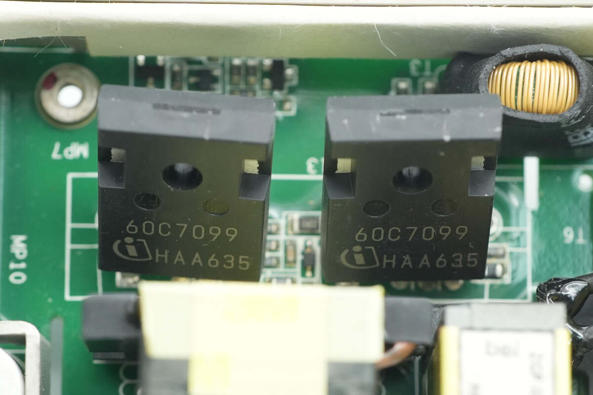
The other path also uses two LLC MOSFETs, both of which are Infineon IPZ60R099C7.
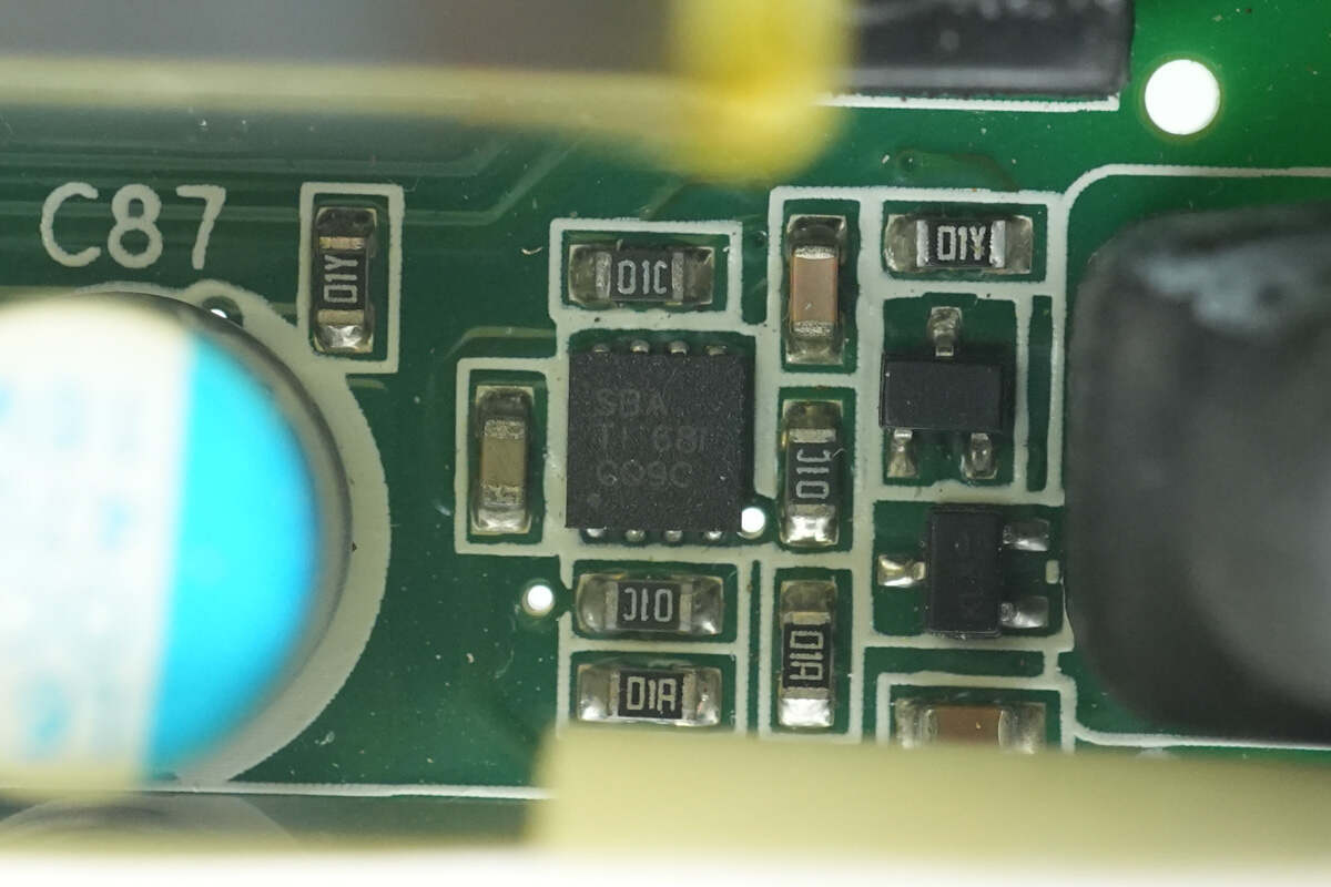
The driver is also the Texas Instruments UCC27524.
The isolation transformer is coated with heat-shrink tubing for insulation.

The resonant inductor is wound with Litz wire.
Close-up of the NPO resonant capacitors.

The primary winding of the transformer is wound with litz wire, while the secondary winding uses copper strips for soldering.
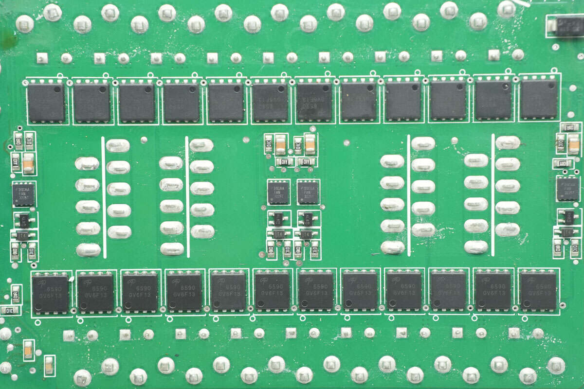
The back of the transformer features 24 synchronous rectifiers and 4 drivers.
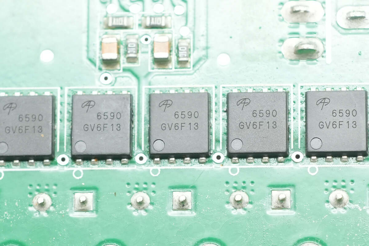
The synchronous rectifiers are from AOS, model AON6590. They are NMOS transistors with a voltage rating of 40V, a conduction resistance of 0.78mΩ, and are packaged in a DFN 5x6 format. These rectifiers feature low conduction resistance and low gate charge, optimized for fast switching. They are suitable for synchronous rectification and isolated DC/DC converters, meeting the requirements for communication and industrial applications.
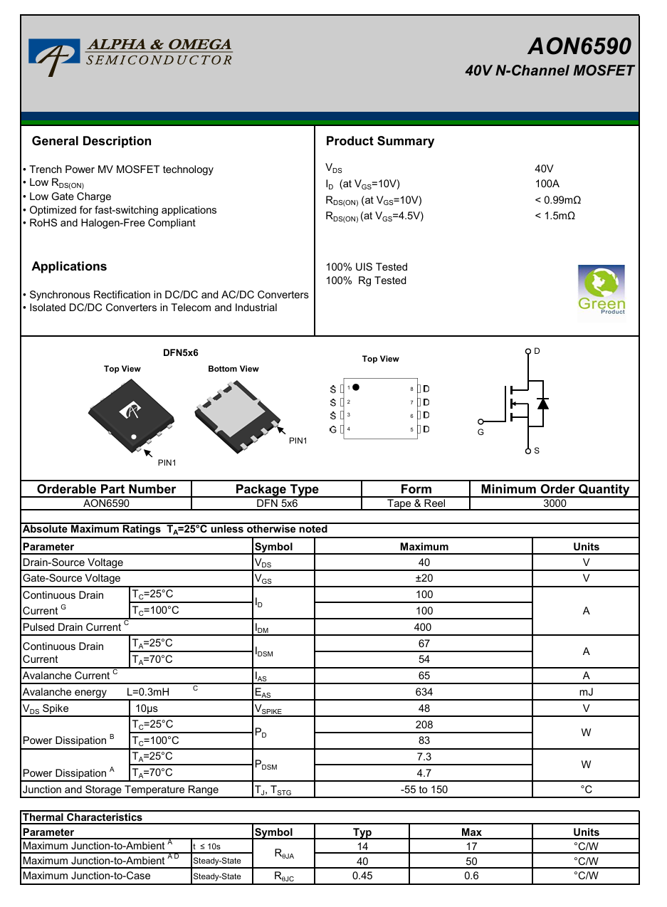
Here is the information about AOS AON6590.
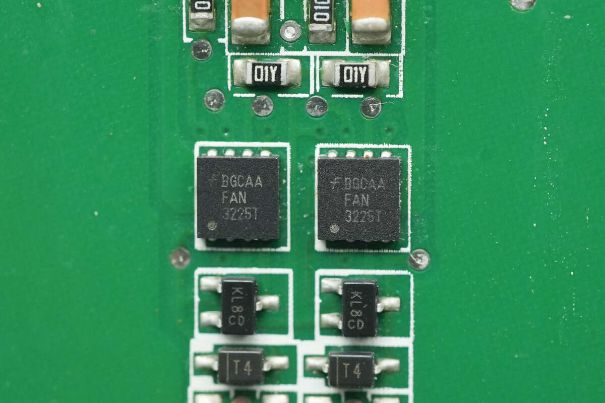
The drivers for the synchronous rectifiers are from Onsemi, model FAN3225T. They are dual-channel low-side drivers, packaged in a WDFN-8 format.
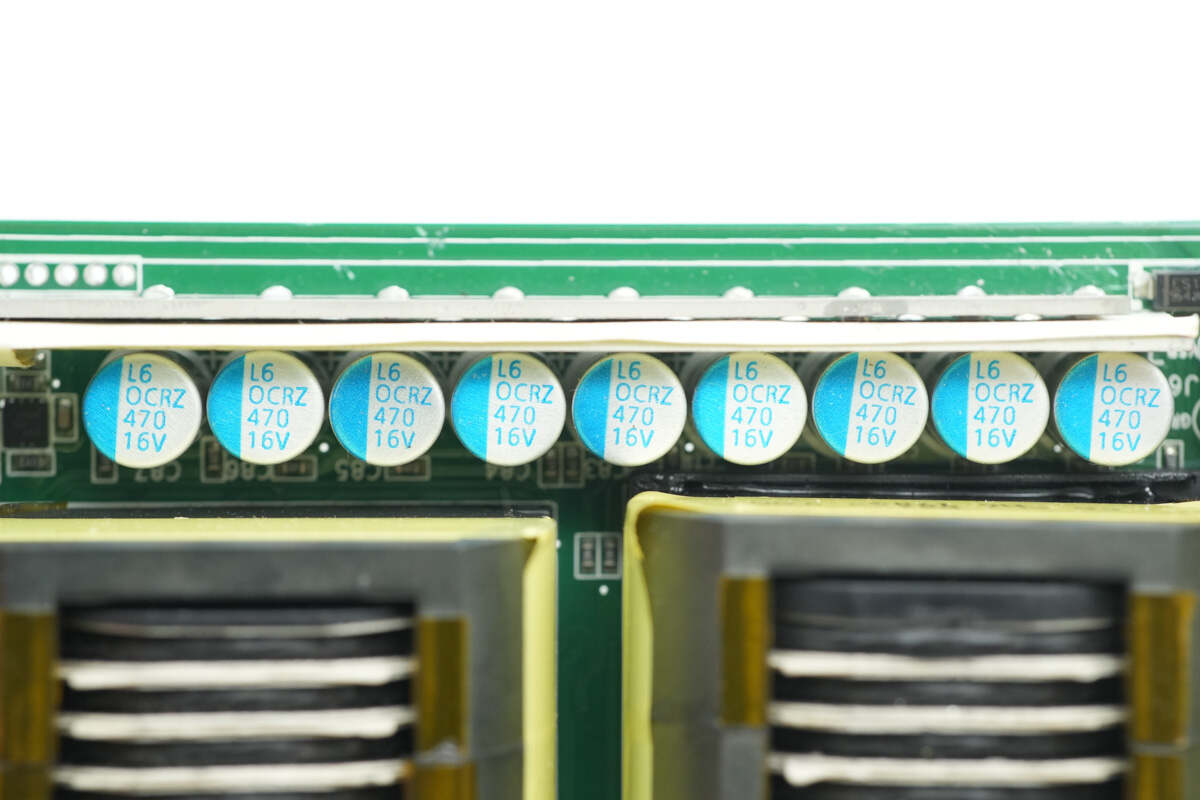
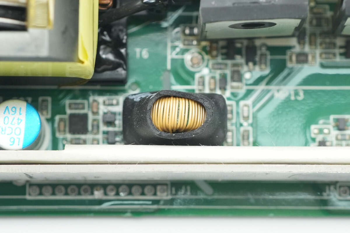
The solid capacitors are from Lelon, part of the OCRZ series of high-polymer solid aluminum electrolytic capacitors, with a specification of 470μF, 16V.
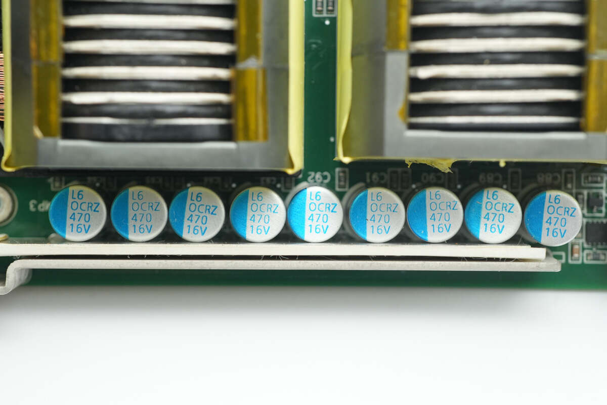
Another set of solid capacitors with the same specifications, totaling 18 pieces.
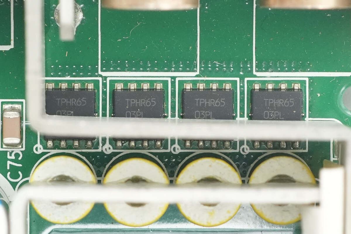
The output control MOSFETs are from Toshiba, model TPHR6503PL. They are NMOS transistors with a voltage rating of 30V, a conduction resistance of 0.41mΩ, and are packaged in SOP Advance format.
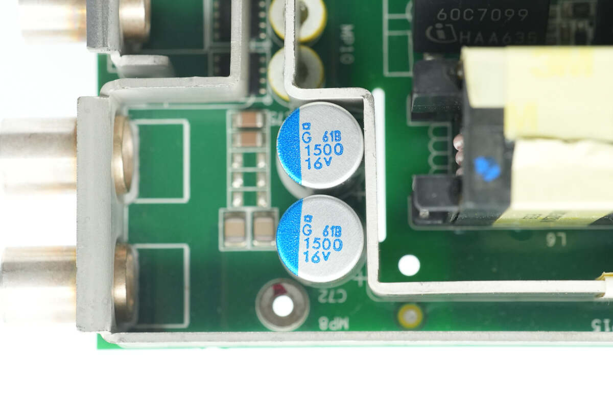
The two output filtering capacitors are from NCC, part of the series of conductive polymer solid aluminum electrolytic capacitors, with a specification of 1500μF, 16V.
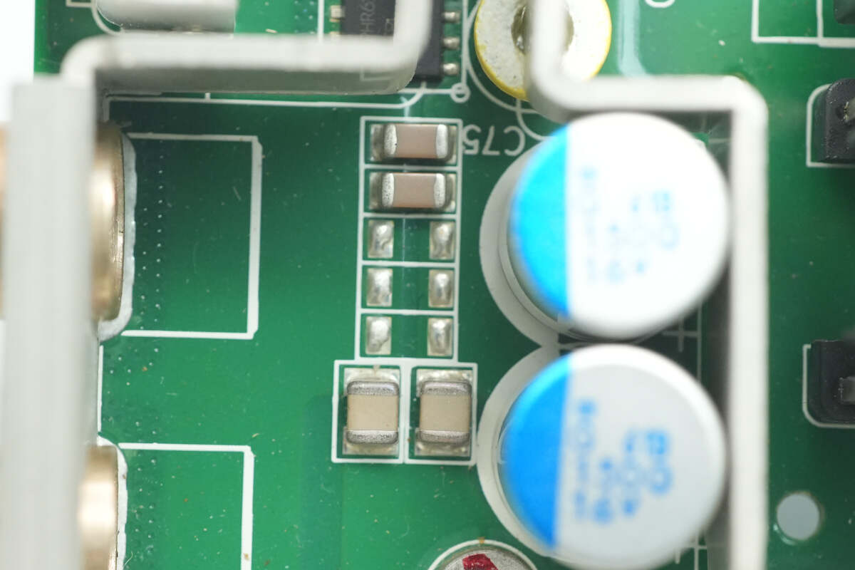
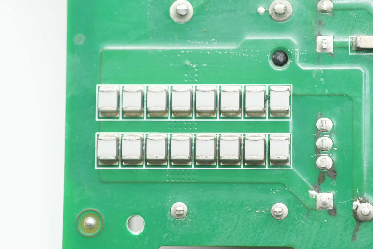
Close-up of the SMD MLCC capacitors.
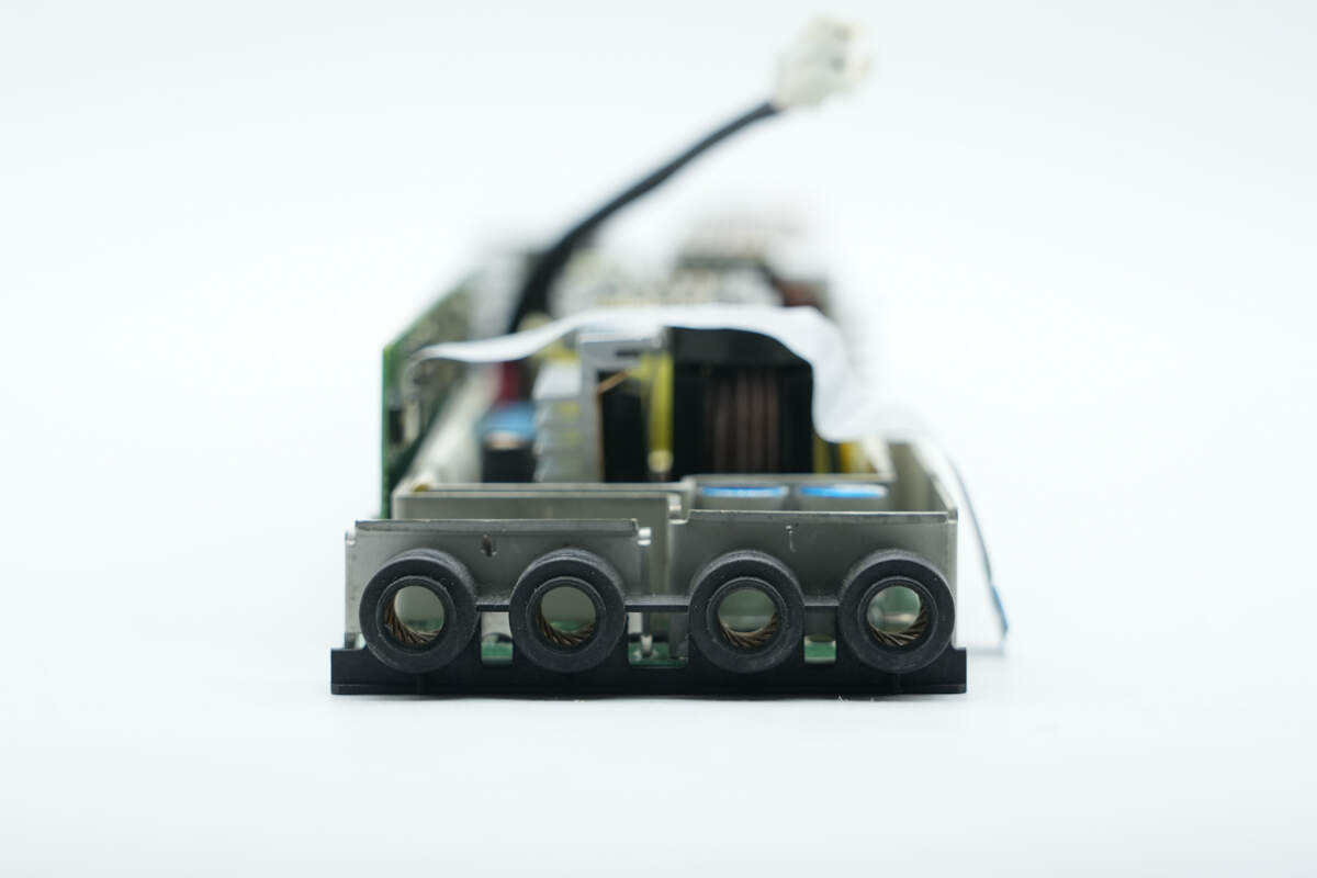
Close-up of the positive and negative output connectors.
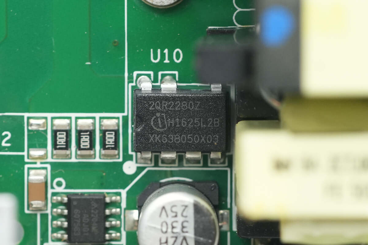
The standby power chip is from Infineon, model ICE2QR2280Z. It integrates an 800V MOSFET and supports a 31W output power under wide input voltage conditions. The chip is packaged in a DIP-7 format.
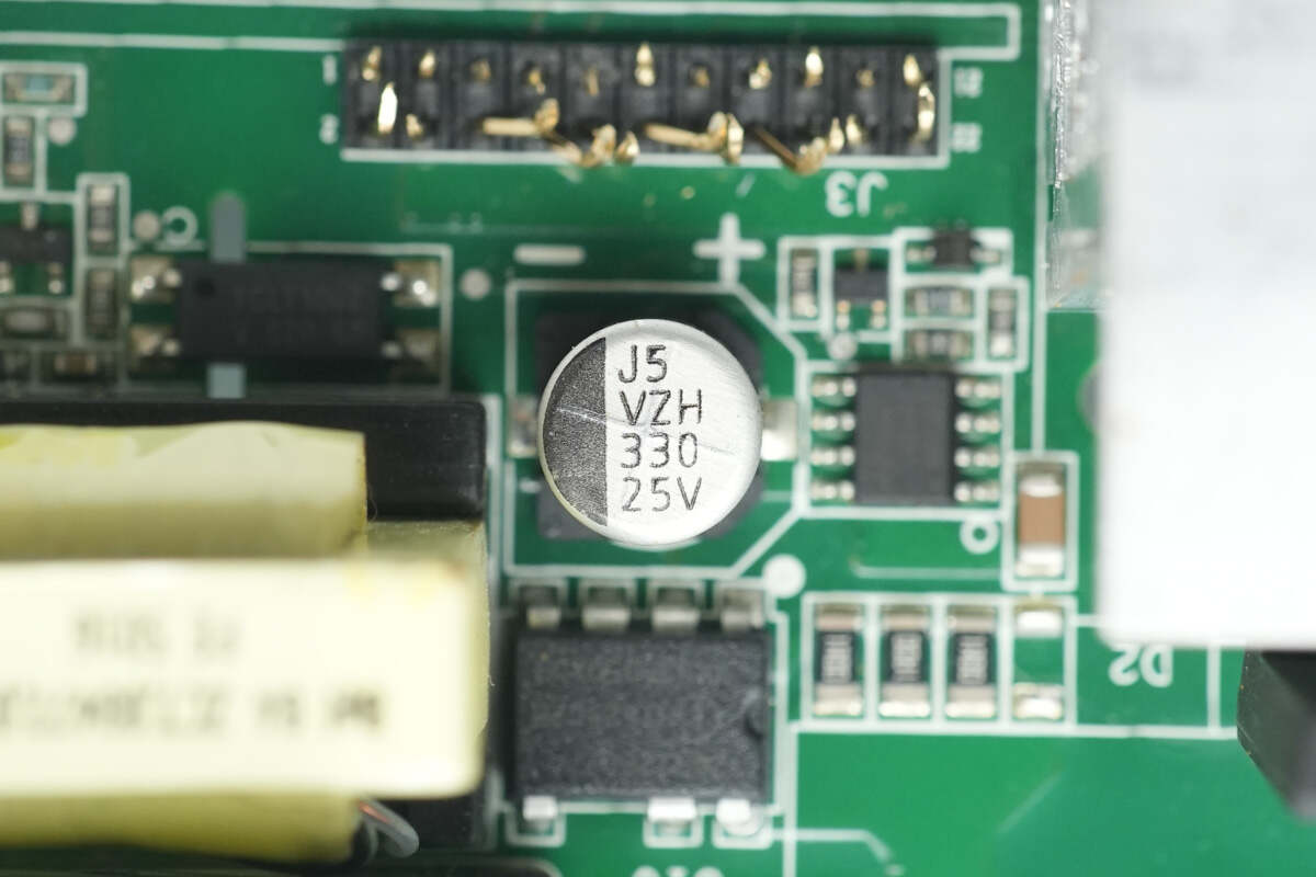
The filtering capacitor has a specification of 330μF, 25V.
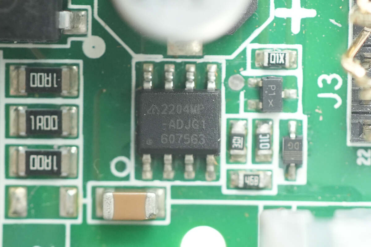
The voltage regulator chip is from DIODES, model AP2204WP. It supports an input voltage range of 2.6-24V and provides an output current of 250mA. The chip is packaged in a PSOP-8 format.
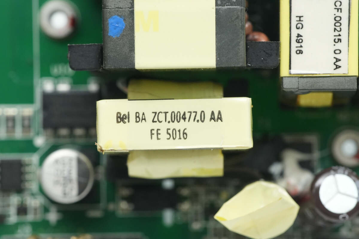
Close-up of the standby power transformer.
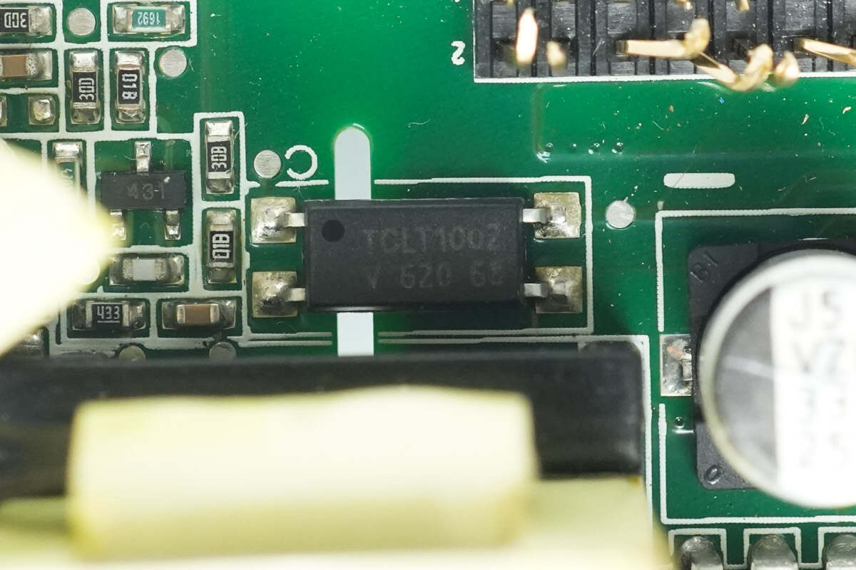
The optocoupler is from VISHAY, model TCLT1002, and is used for output voltage feedback.
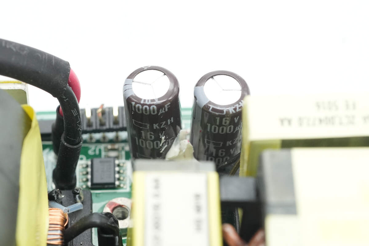
The output filtering capacitors are from NCC, with a specification of 16V, 1000μF.
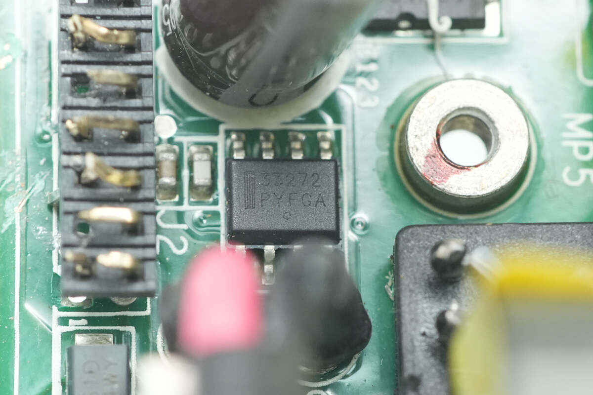
The operational amplifier is from Onsemi, model MC33272A. It is a high-voltage, high-slew-rate dual op-amp, offering excellent phase and gain margin, and is packaged in an SOIC-8 format.
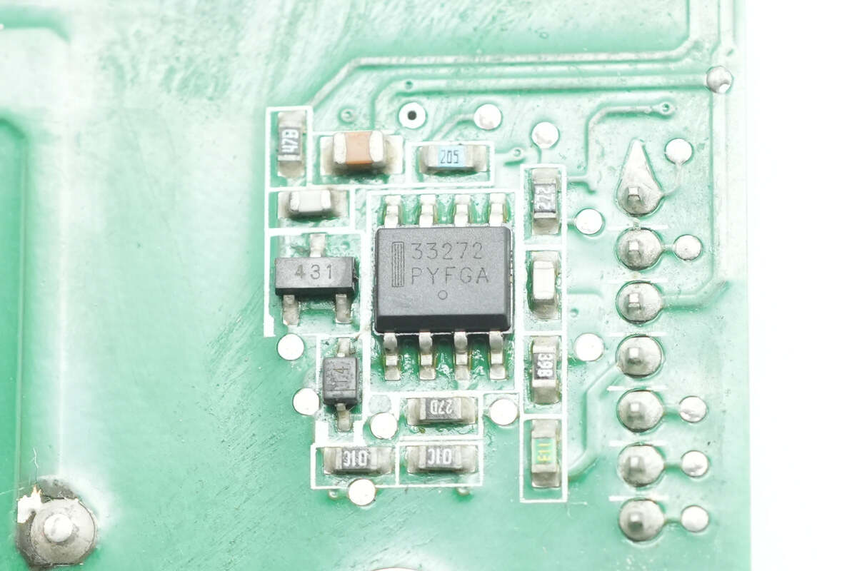
The other operational amplifier has the same model.
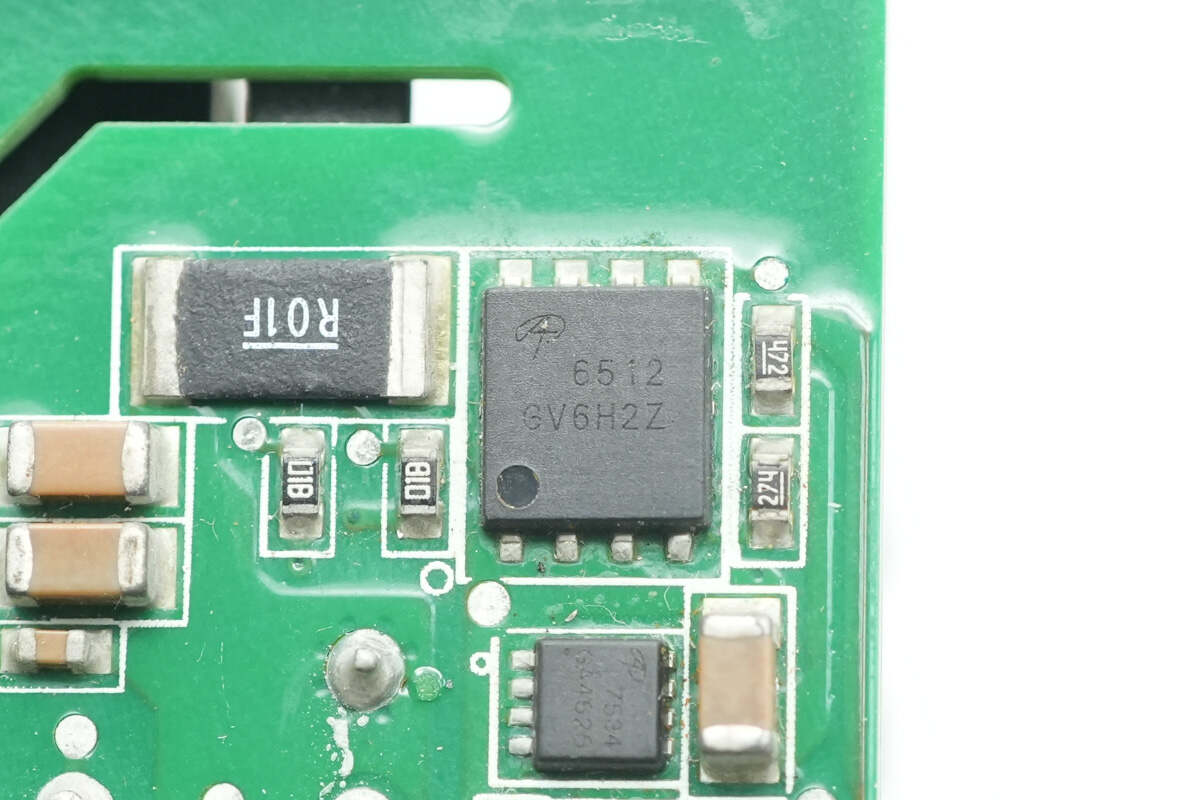
The power switching MOSFET is from AOS, model AON6512. It is an NMOS with a voltage rating of 30V, a conduction resistance of 1.7mΩ, featuring low gate charge and high current capability. It is suitable for DC/DC converter applications and is packaged in a DFN 5x6 format.
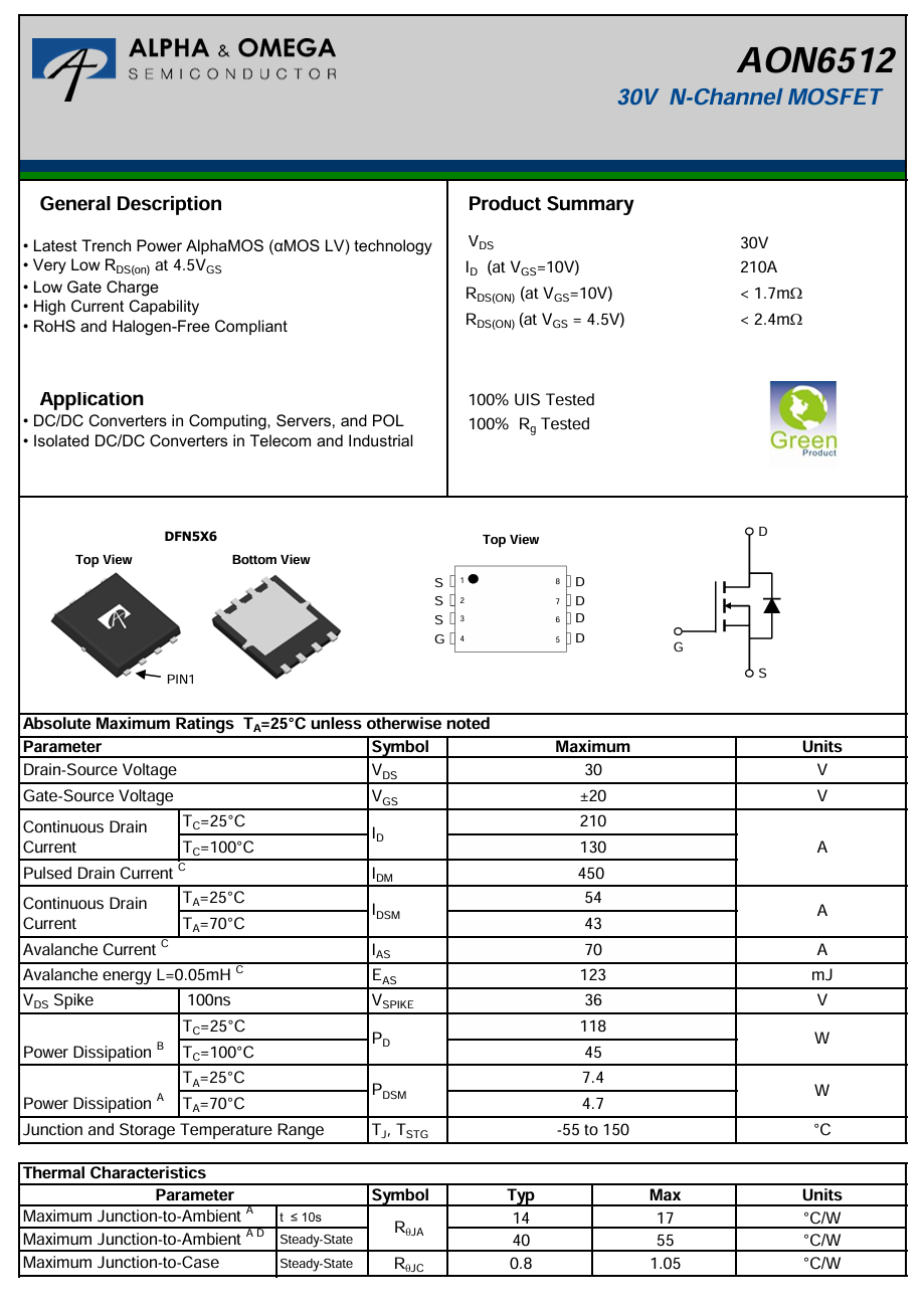
Here is the information about AOS AON6512.
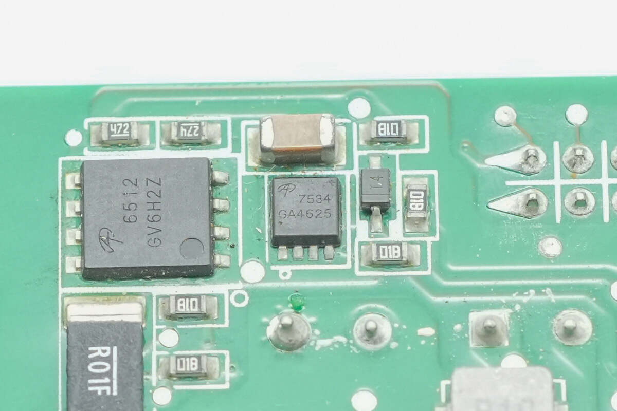
The power switching MOSFET is from AOS, model AON7534. It is an NMOS with a voltage rating of 30V, a conduction resistance of 4.1mΩ, featuring low gate charge and high current capability. It is suitable for DC/DC converter applications and is packaged in a DFN 3x3 EP format.
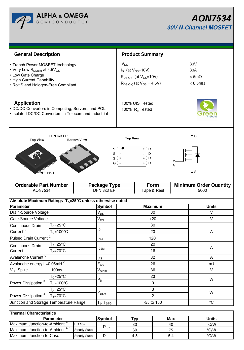
Here is the information about AOS AON7534.
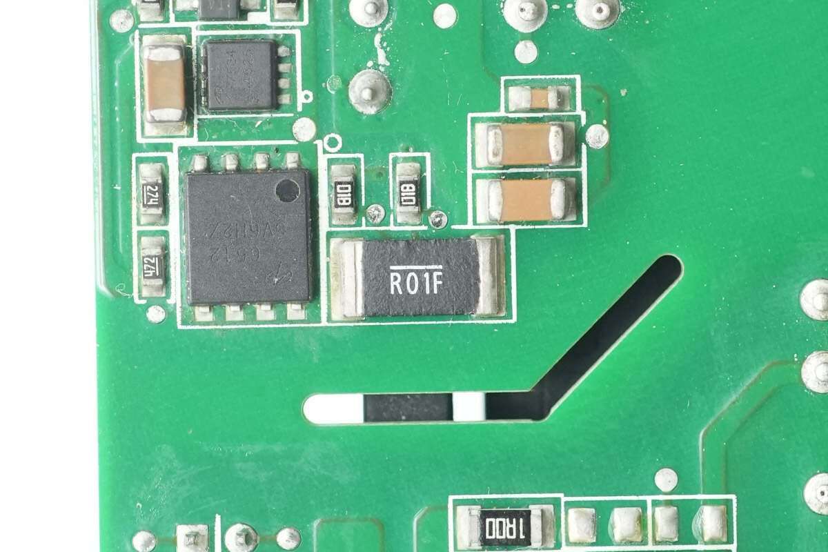
Close-up of the 10mΩ sampling resistor.
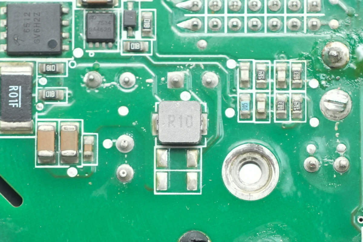
Close-up of the 0.1μH alloy inductor.
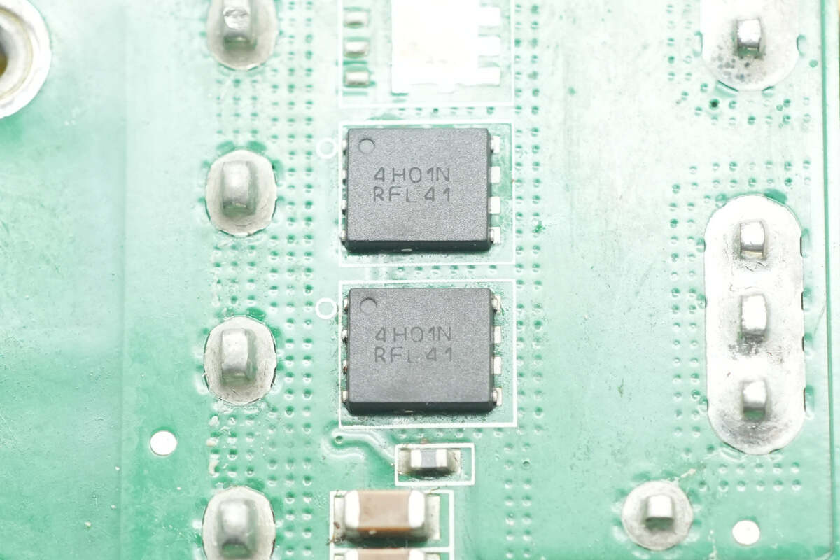
The power switching MOSFETs are from Onsemi, marked with 4H01N, model NTMFS4H01N. They are NMOS transistors with a voltage rating of 25V, a conduction resistance of 0.55mΩ, and are packaged in an SO8-FL format.
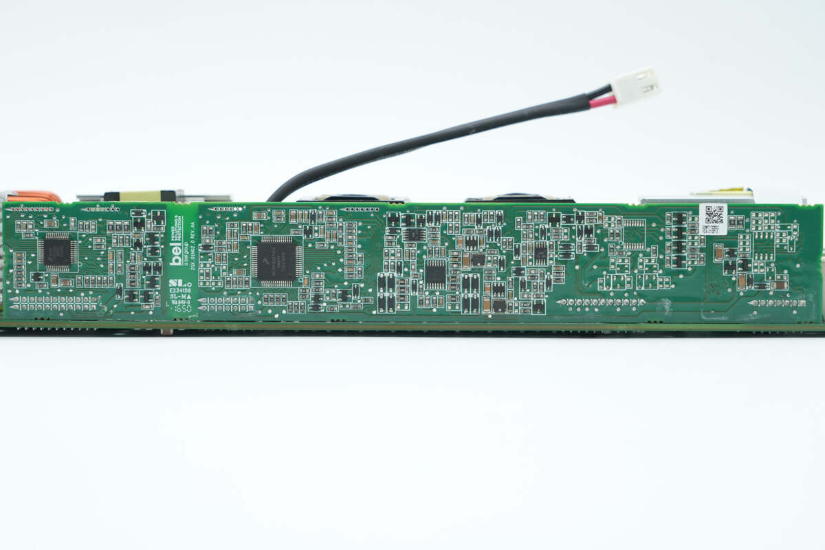
The control PCB is soldered on the side of the PCBA module.
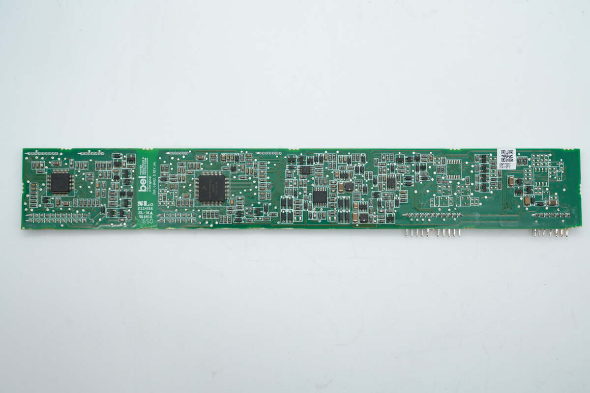
Remove the control PCB. On the left side, there is a PFC controller, an LLC controller, buck chips, and operational amplifiers.
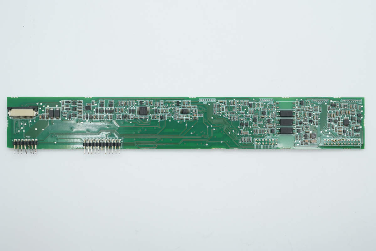
On the back, there are optocouplers, comparators, operational amplifiers, buck regulators, and memory chips.
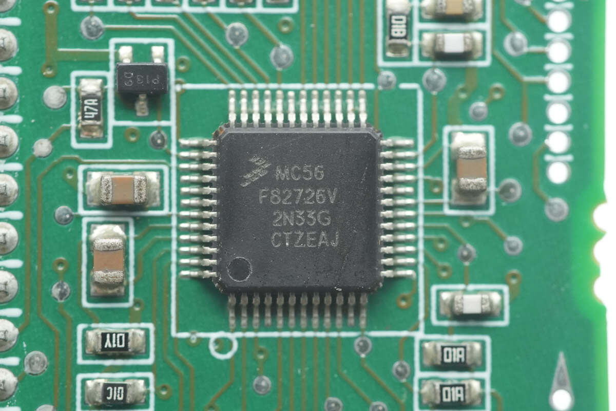
The PFC controller is from NXP, model MC56F82726VLF. It integrates a 32-bit 56800EX core with a clock speed of 100MHz, and includes 32KB of FLASH and 6KB of SRAM. It supports an operating voltage range of 2.7-3.6V and is packaged in an LQFP48 format.
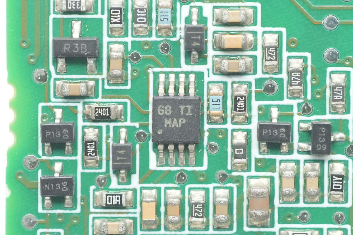
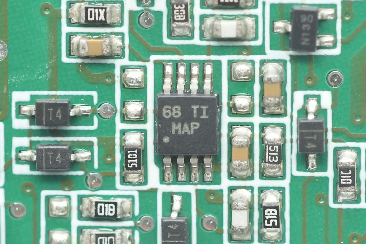
The voltage comparator is from Texas Instruments, marked with MAP, model LM2903. It is a general-purpose dual comparator, packaged in a VSSOP8 format.
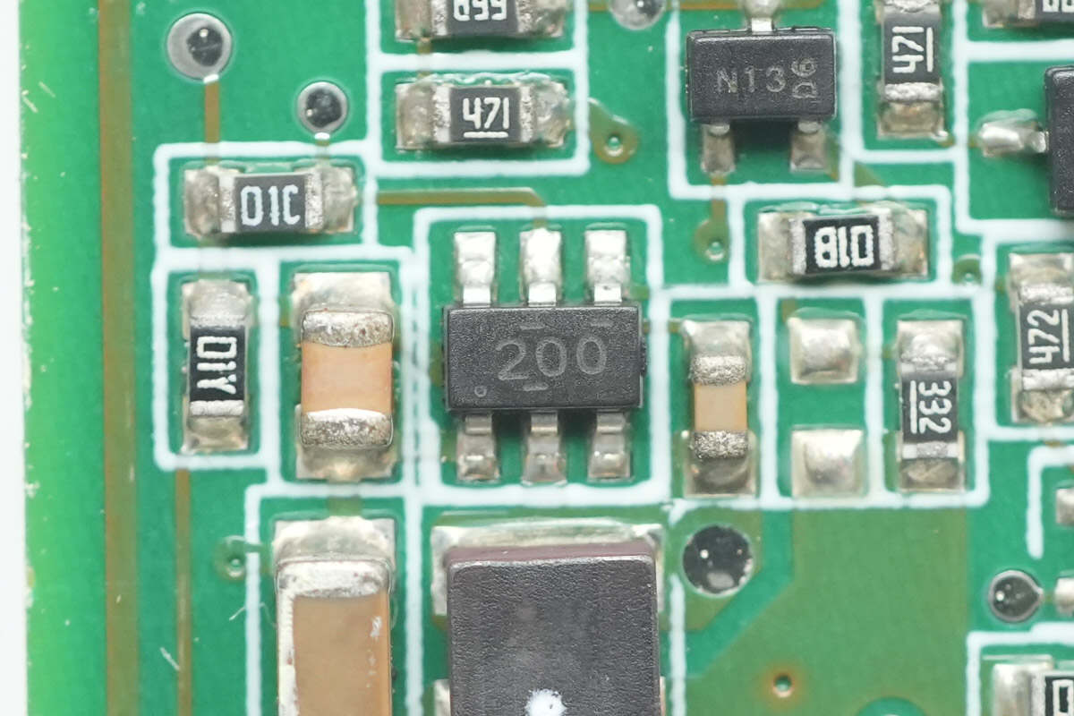
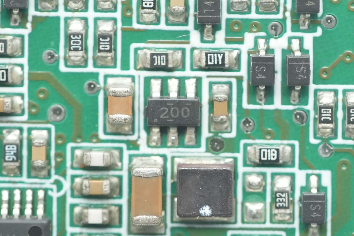
The buck chip is from Texas Instruments, marked with 200, model TPS562200. It integrates MOSFETs and supports an input voltage of up to 17V with an output current of 2A. It is packaged in an SOT23 format.
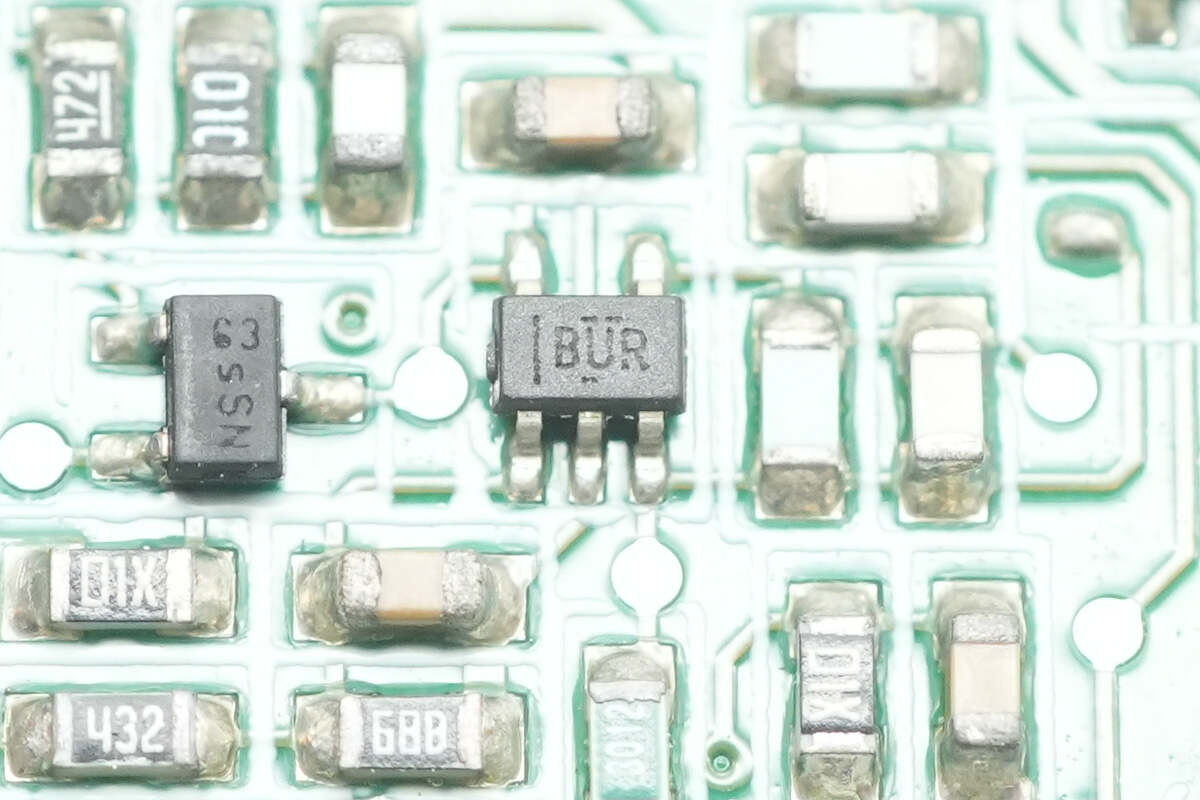
The operational amplifier is from Texas Instruments, marked with BUQ, model OPA376. It is a precision low-static-current op-amp that supports rail-to-rail input and output, packaged in an SOT-23 format.
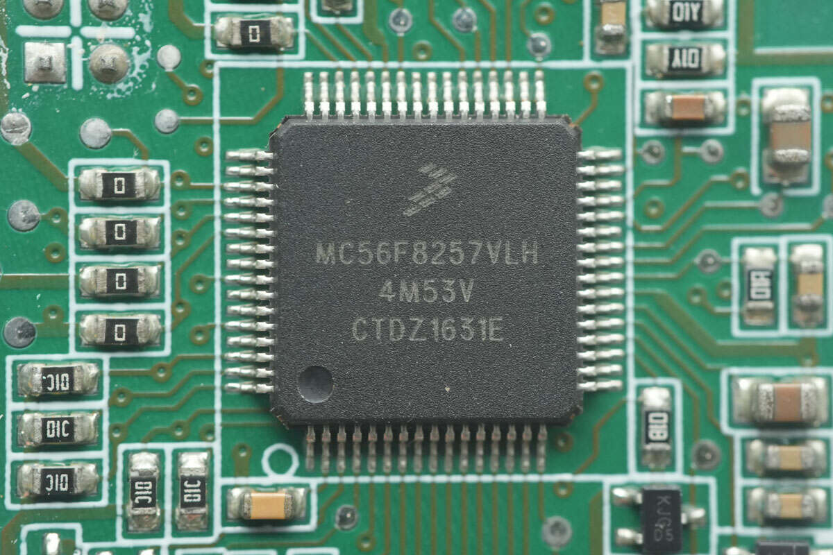
The LLC controller is from NXP, model MC56F8257VLH. It integrates a 16-bit 56800E core with a clock speed of 60MHz, and includes 64KB of FLASH and 8KB of SRAM. It supports an operating voltage range of 3-3.6V and is packaged in an LQFP64 format.
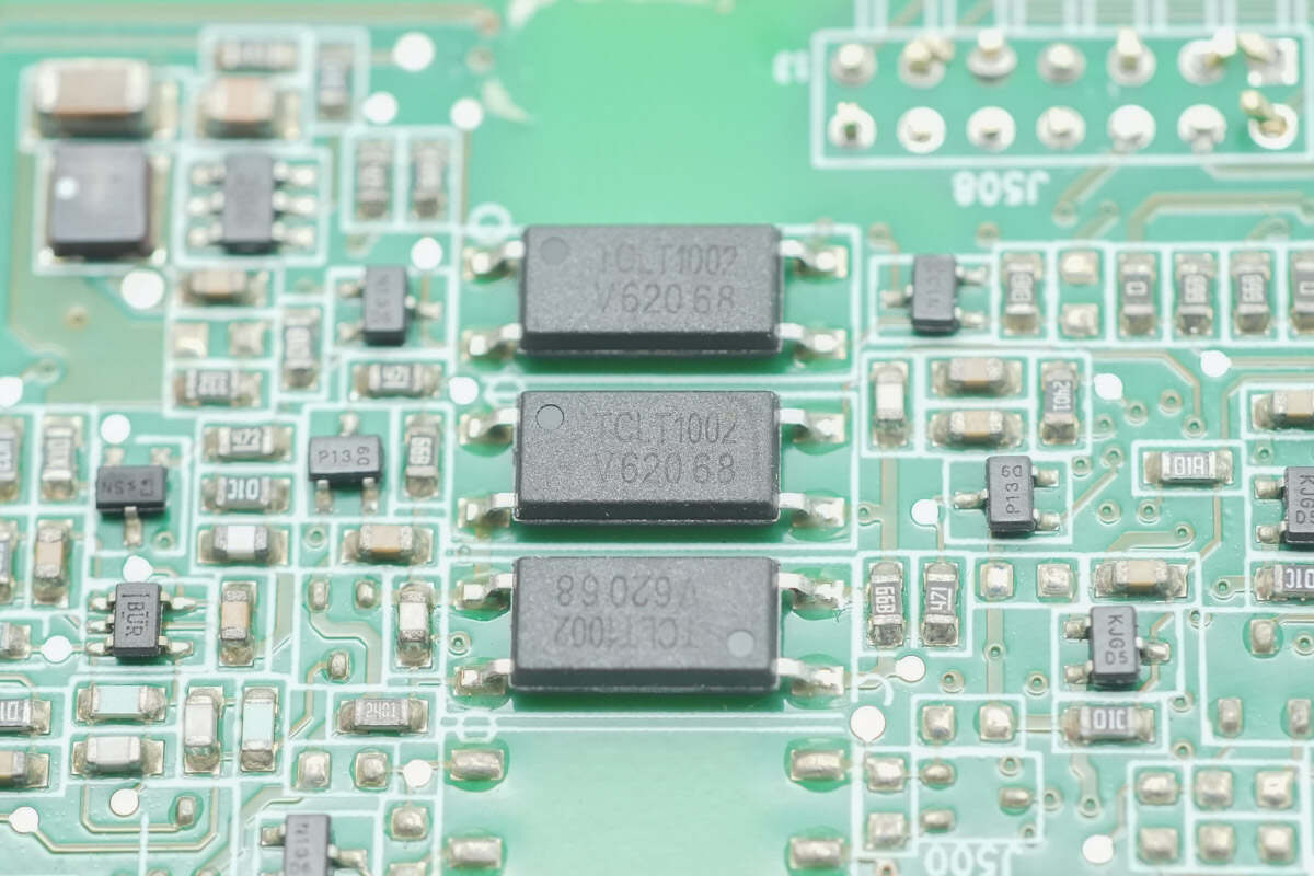
The VISHAY TCLT1002 optocouplers are used for isolation communication between the PFC and LLC controllers.
The operational amplifier is from Texas Instruments, model LM2904. It is a standard dual op-amp with a voltage operating range of 3-36V and is packaged in a VSSOP8 format.
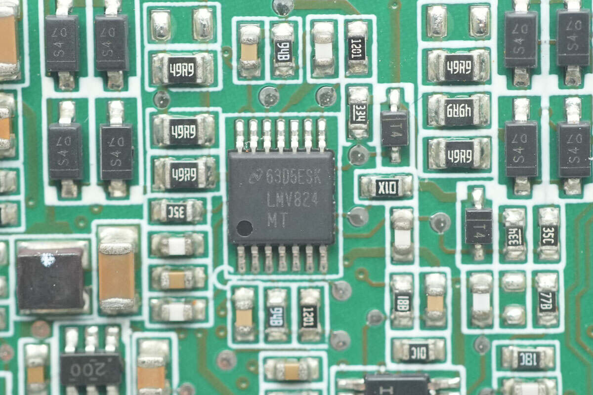
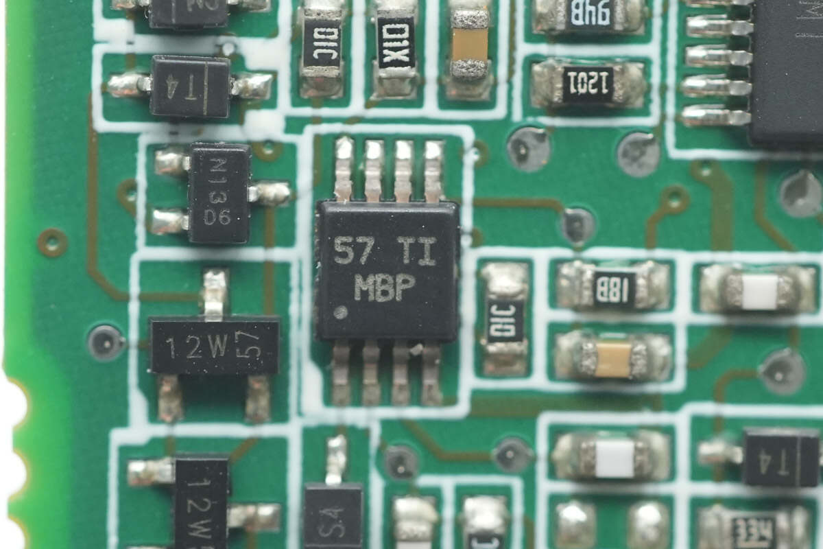
The operational amplifier is from Texas Instruments, model LMV824. It is a quad op-amp with rail-to-rail output, packaged in a TSSOP14 format.
The buck chip is from Texas Instruments, model TPS562200.
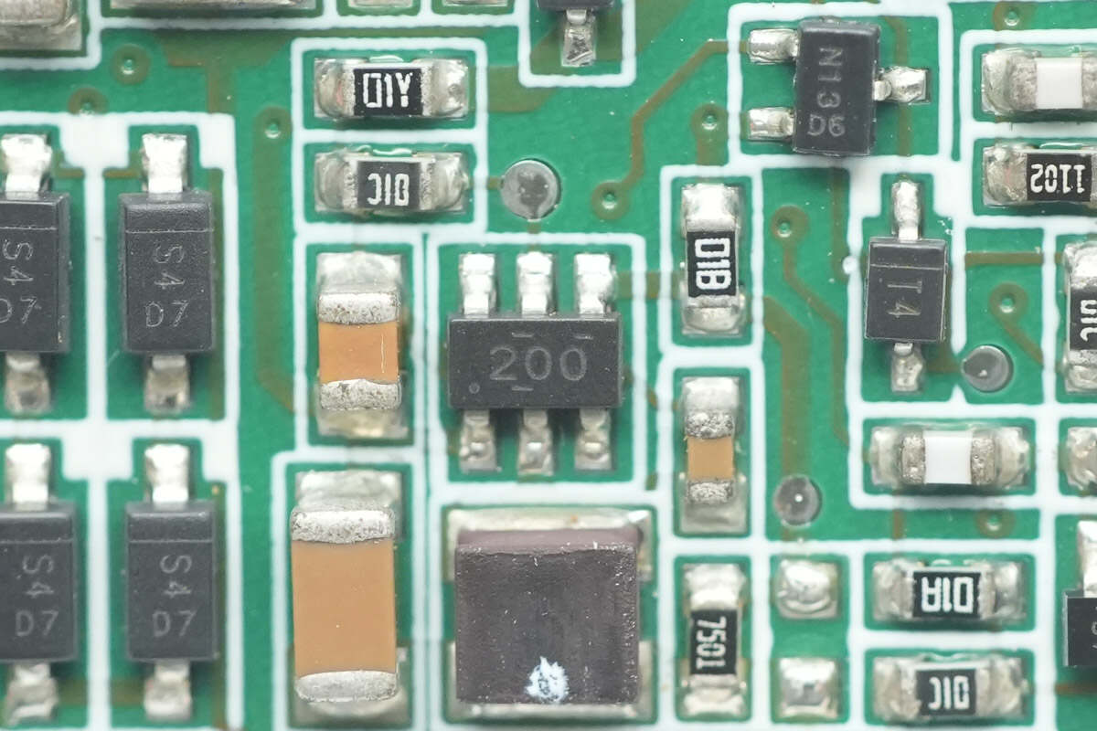
The other buck chip has the same model.
The voltage comparator is from Texas Instruments, model LM2903.
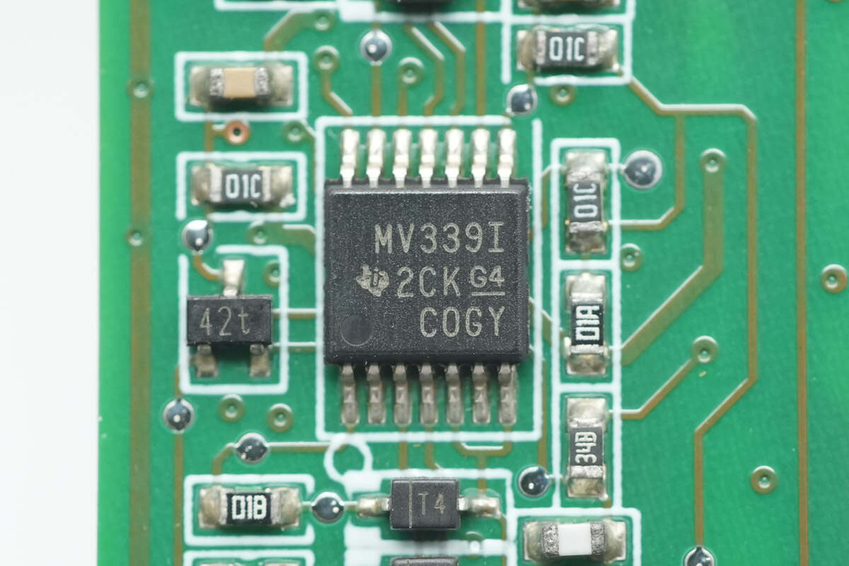
The voltage comparator is from Texas Instruments, model LMV339. It is a quad-channel general-purpose low-voltage comparator, packaged in a TSSOP14 format.
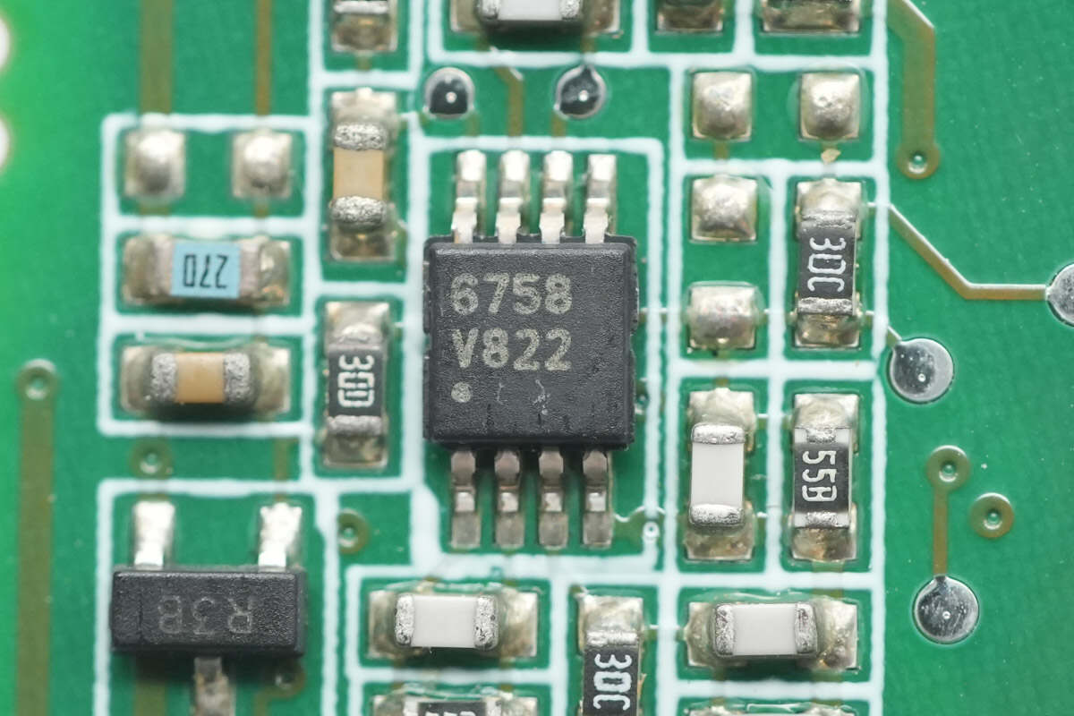
The operational amplifier is from Texas Instruments, model LMV822. It is a dual-channel, low-voltage, low-power, rail-to-rail output op-amp, packaged in a VSSOP8 format.
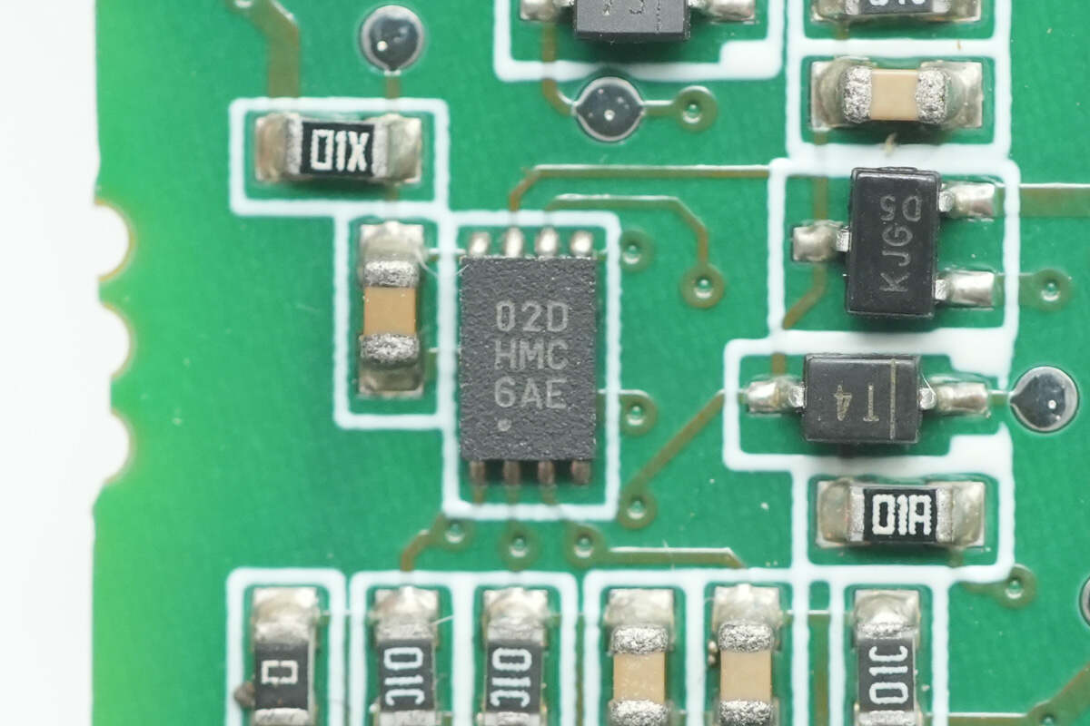
Close-up of a chip marked with 02DHMC.

Well, those are all components of the Bel Fuse 3000W GaN Server Power Supply.
Summary of ChargerLAB
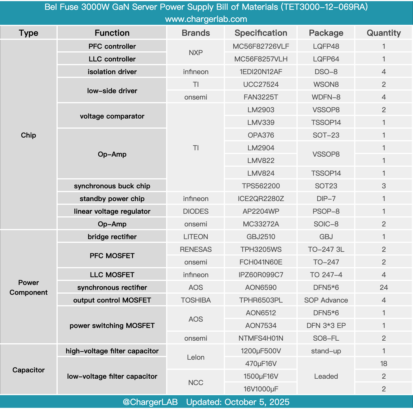
Here is the component list of the Bel Fuse 3000W GaN Server Power Supply for your convenience.
It supports a wide input voltage range, with a rated output power of 3000W. One side of the power supply is equipped with a handle, while the other side features dedicated connectors for AC input and DC output connections. It has an integrated cooling fan and indicator lights for power and operational status monitoring.
After taking it apart, we found that it uses the NXP MC56F82726VLF controller for the totem-pole PFC control, paired with Infineon 1EDI20N12AF isolated drivers. It utilizes RENESAS TPH3205 GaN FETs, while the low-speed half-bridge MOSFETs are Onsemi FCH041N60E.
The LLC controller uses NXP MC56F8257VLH, with Texas Instruments UCC27524 drivers. The LLC MOSFETs are Infineon IPZ60R099C7, and the synchronous rectifiers are AOS AON6590, driven by Onsemi FAN3225T drivers.
The module features an input PCB with the AC input connected via wires. The PCBA module has a control PCB soldered on the side, housing both the PFC and LLC controllers. High-voltage filter capacitors and solid capacitors are sourced from Lelon, with additional filtering provided by NCC capacitors. The positive and negative output connections use copper busbars to reduce resistance. The components are all from well-known brands, and the internal construction is solid and reliable.
Related Articles:
1. Teardown of Gospower 1300W DC Server Power Supply (G1232-1300WND)
2. Teardown of Xiaomi 17 Pro Retro Handheld Console Case (25099TC43C)
3. Teardown of Huawei SuperPower 100W 12000mAh Power Bank (P0020)