Introduction
Xiaomi recently launched a magnetic stand power bank with a built-in 10,000mAh battery. It features a USB-C cable and USB-C port supporting 30W input and 33W output, enabling fast charging both ways.
Compared to previous models, this version adds a foldable metal stand that supports magnetic wireless charging in both landscape and portrait modes, with up to 15W EPP wireless power. An LED display shows the remaining battery level. Next, let’s take it apart to see its internal components and structure.
Product Appearance
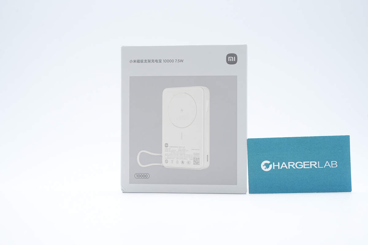
The front of the packaging features the Xiaomi logo, product name, and an image of the device.
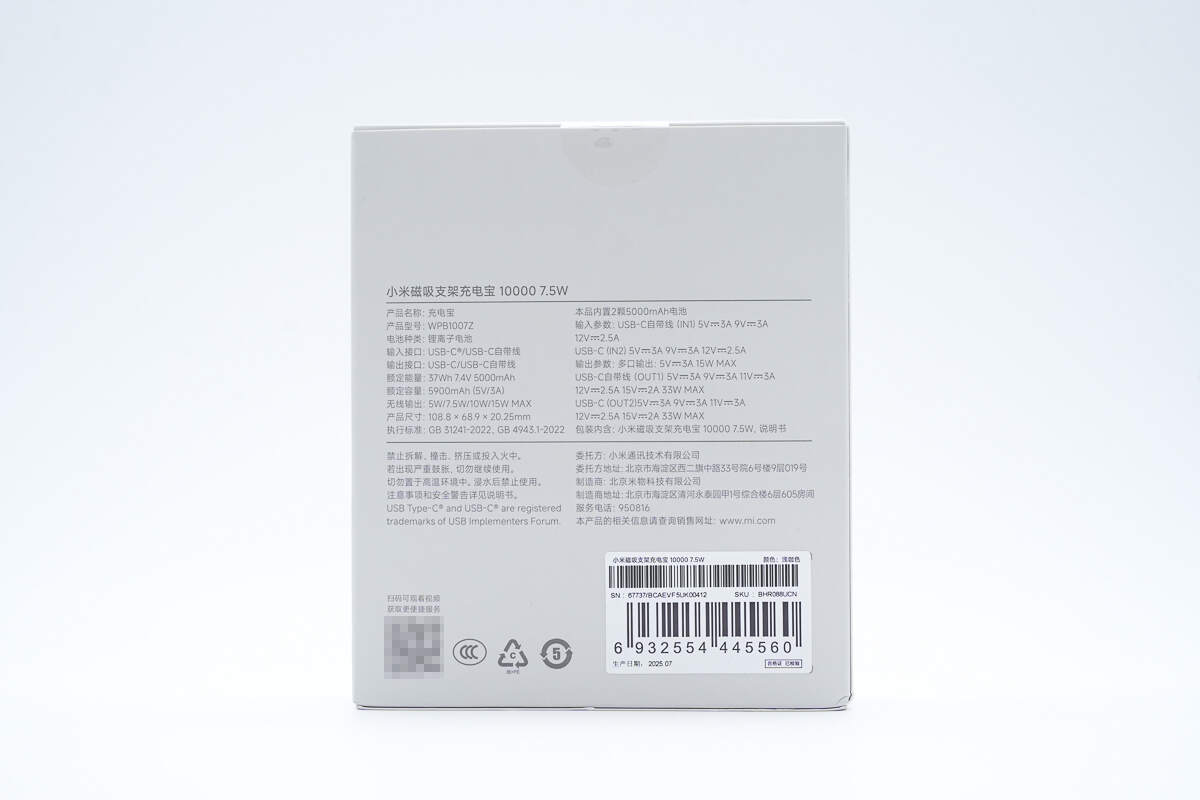
The back of the packaging displays the specifications and safety information.
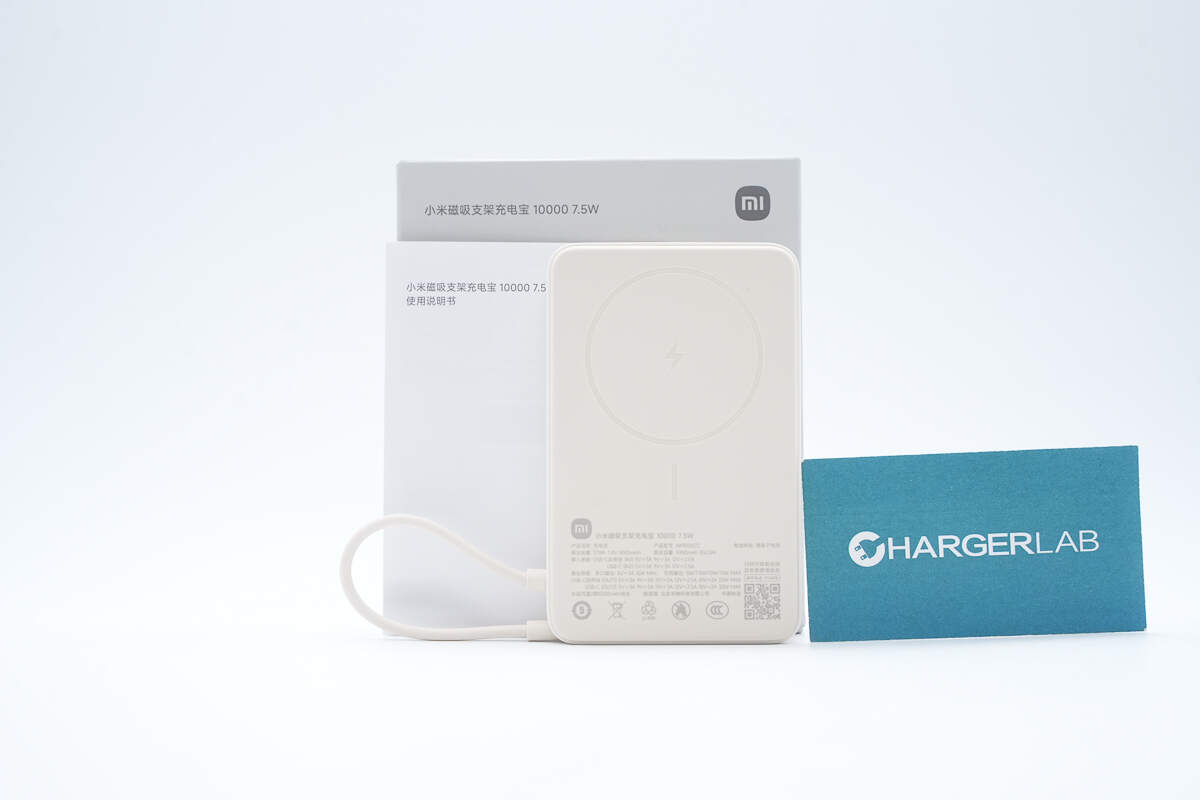
The package includes the power bank and some documents.
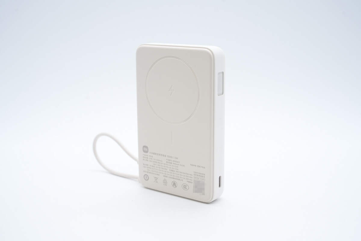
It comes in four colors: blue, brown, purple, and gray. The case is made of flame-retardant PC+ABS material with a fine matte texture.
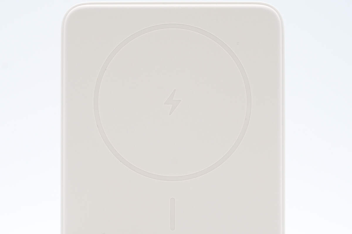
The top area is designated for wireless charging.
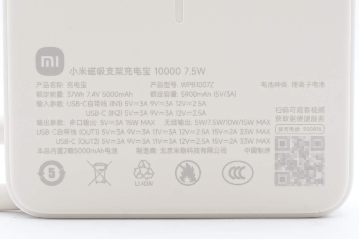
At the bottom, the following parameters are printed:
Model: WPB1007Z
Battery Type: Lithium-ion battery
Rated Energy: 37Wh 7.4V 5000mAh
Rated Capacity: 5900mAh (5V 3A)
Input Parameters:
USB-C Built-in Cable: 5V 3A, 9V 3A, 12V 2.5A
USB-C Port: 5V 3A, 9V 3A, 12V 2.5A
Output Parameters:
Multi-port Output: 5V 3A, 15W MAX
Wireless Output: 5W / 7.5W / 10W / 15W MAX
USB-C Built-in Cable: 5V 3A, 9V 3A, 11V 3A, 12V 2.5A, 15V 2A, 33W MAX
USB-C Port: 5V 3A, 9V 3A, 11V 3A, 12V 2.5A, 15V 2A, 33W MAX
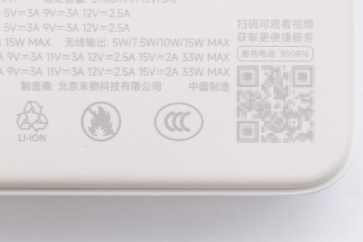
It has passed the CCC certification.
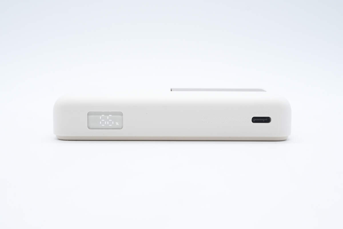
This side features a USB-C port and an LED display.
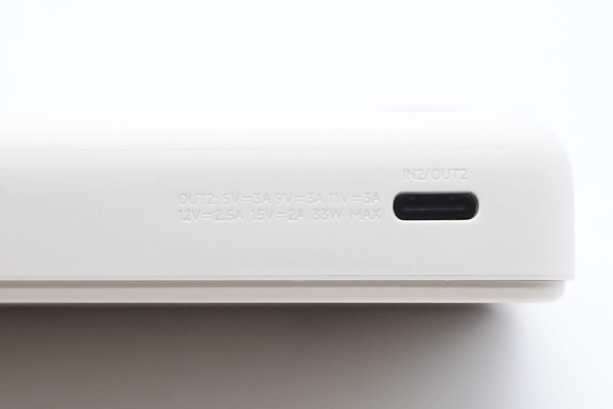
The port is labeled IN2/OUT2 along with the specifications.
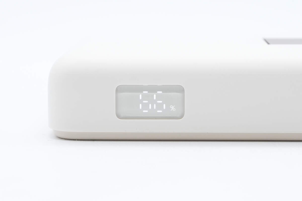
The LED display shows the remaining battery level.
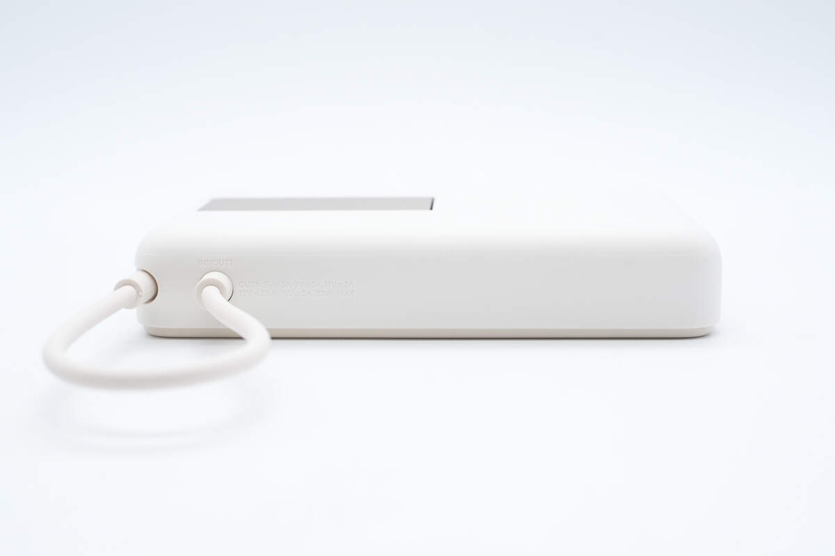
The other side has an integrated USB-C cable, with both ends designed for bend resistance.
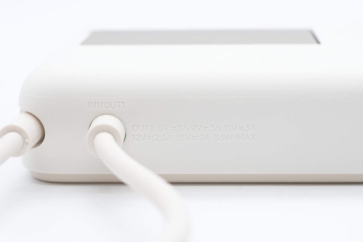
The markings include IN1/OUT1 along with the specifications.
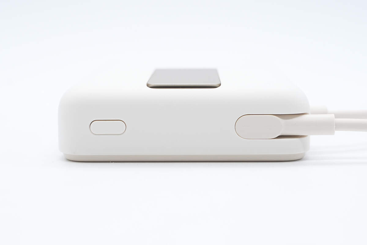
The power button and cable storage slot are located at the bottom.
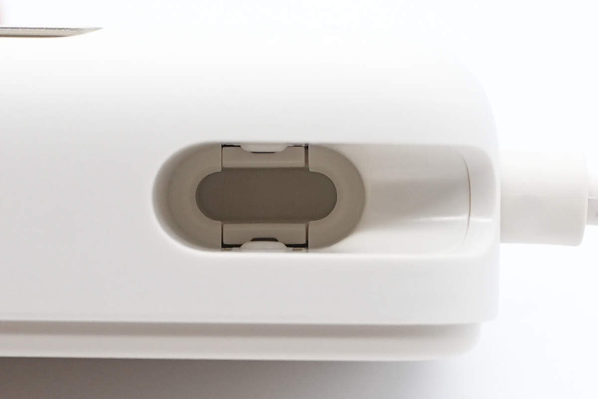
The slot contains a USB-C connector securing structure.
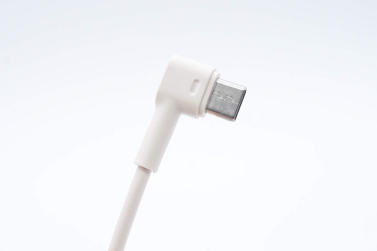
The USB-C built-in cable connector features a 90° angled design.
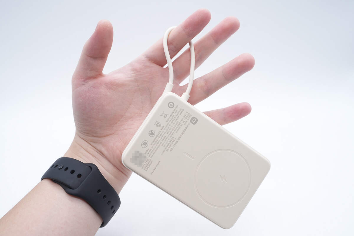
The built-in cable can also be used as a carrying strap for easy portability.
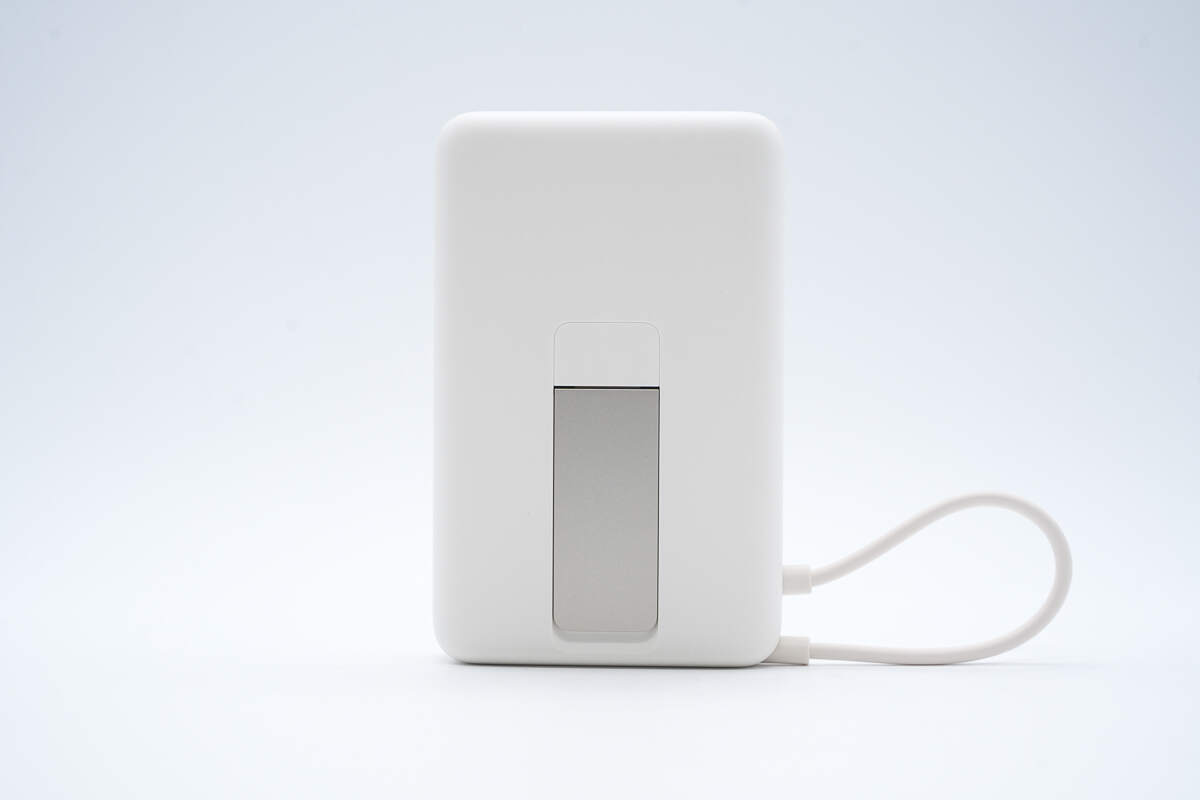
There is a metal stand on the back.
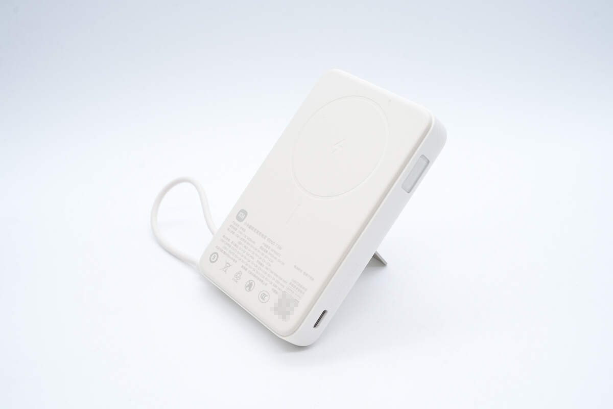
The angle can be adjusted for a better charging experience.
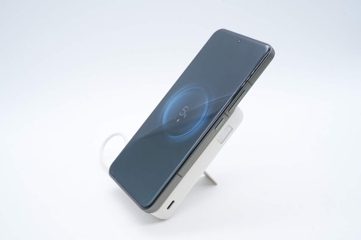
Using the Xiaomi 15 Pro as an example, the phone can be placed vertically for wireless charging.
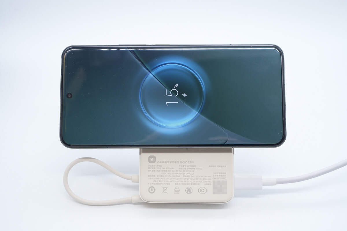
It can also be placed horizontally for charging. Notably, the power bank supports charging while discharging.
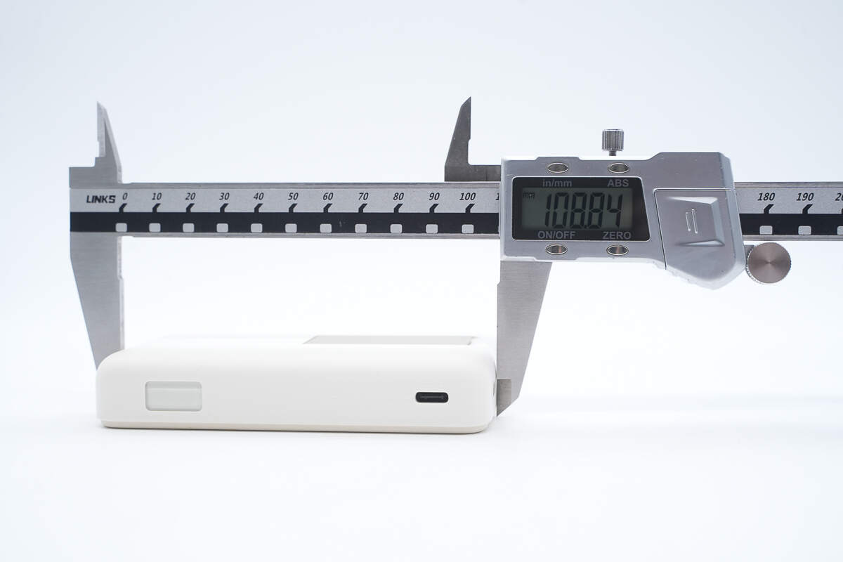
The length of the power bank is about 108.84 mm (4.29 inches).
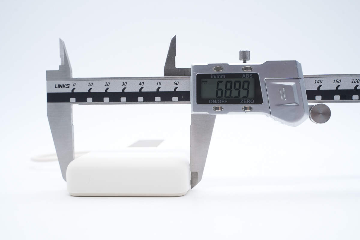
The width is about 68.99 mm (2.72 inches).
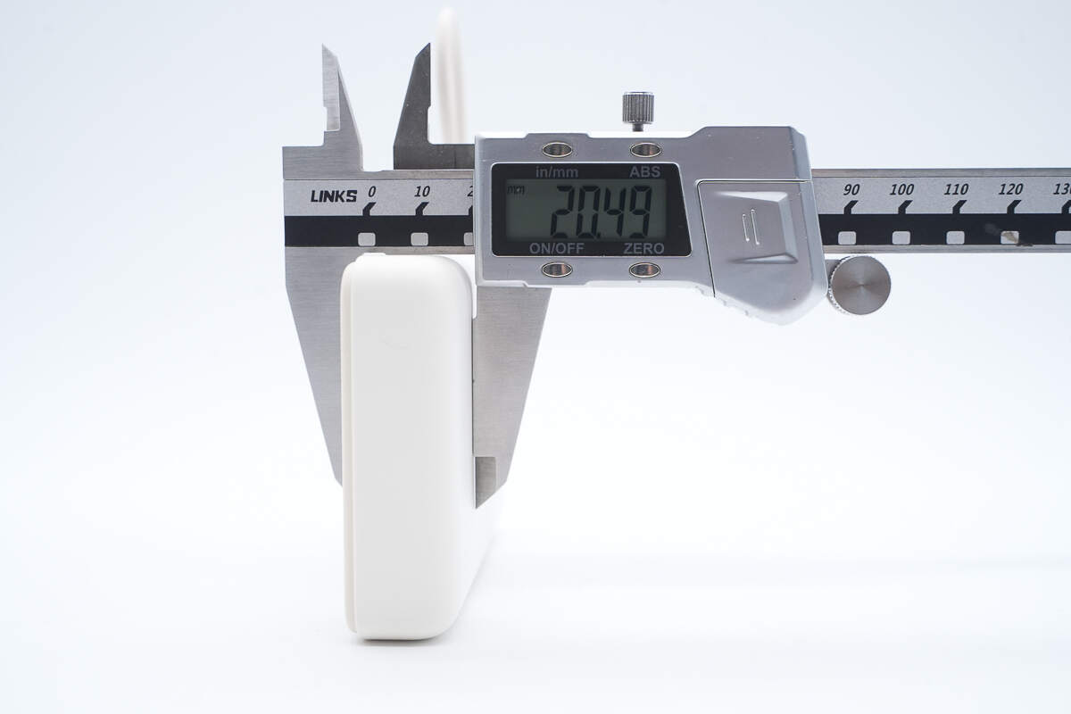
The thickness is about 20.49 mm (0.81 inches).
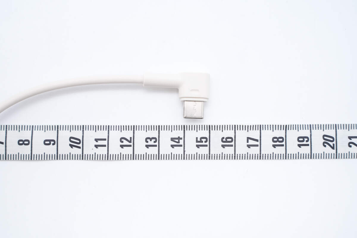
The length of the cable is about 15 cm (5.91 inches).
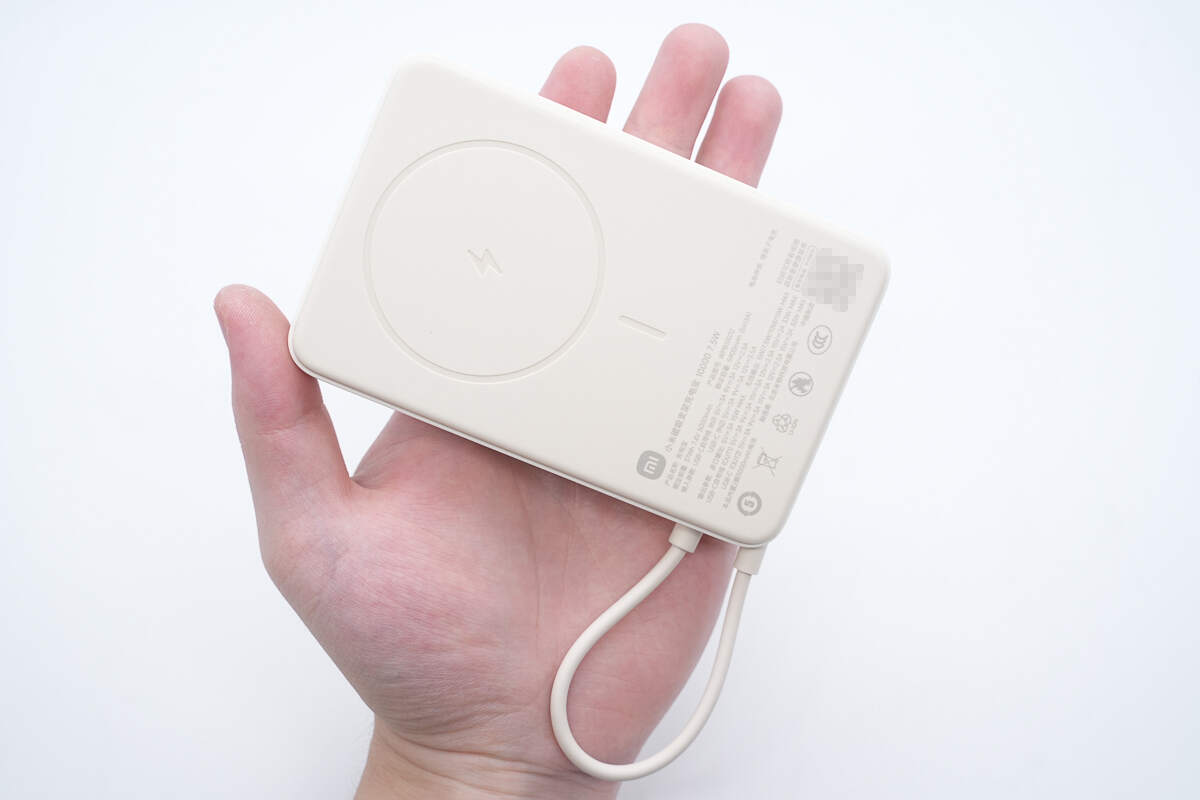
That's how big it is in the hand.
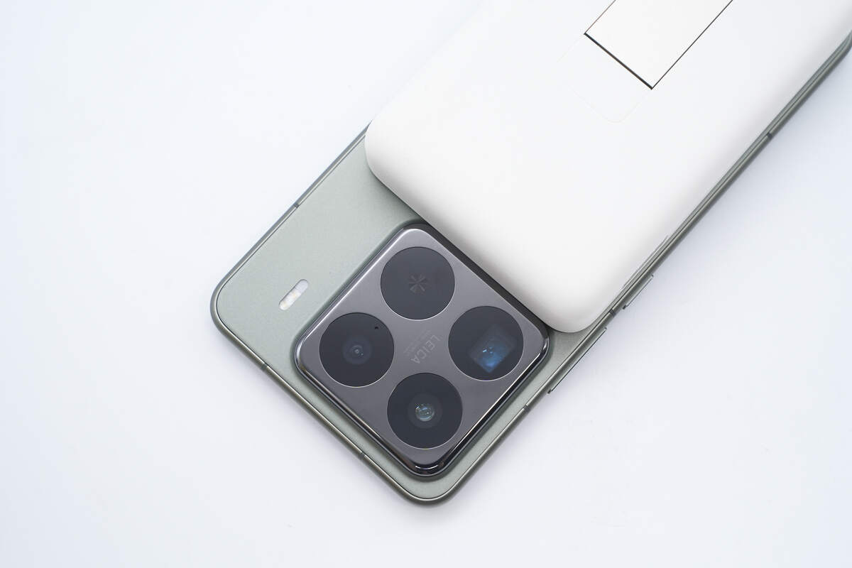
The power bank is perfectly sized so that when charging the Xiaomi 15 Pro, it does not block the rear camera module.
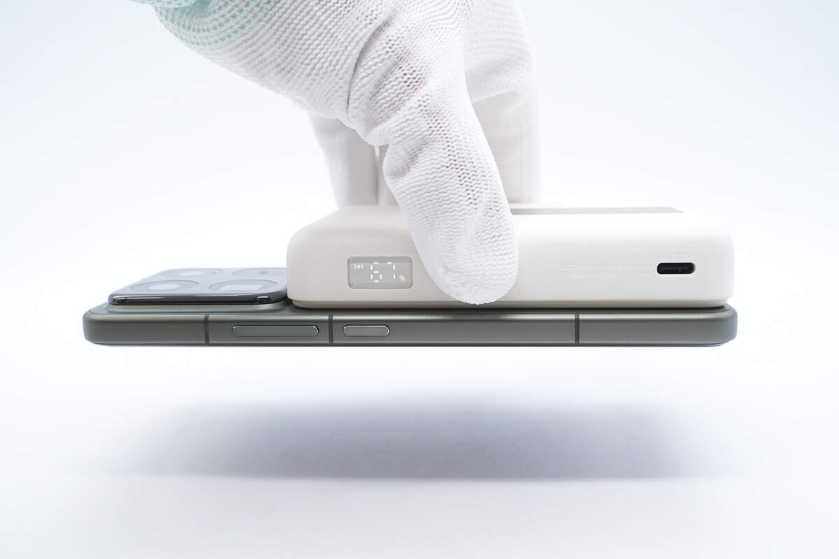
The power bank contains 17 built-in N52H magnets, providing strong magnetic attraction that securely holds the Xiaomi 15 Pro without falling off.
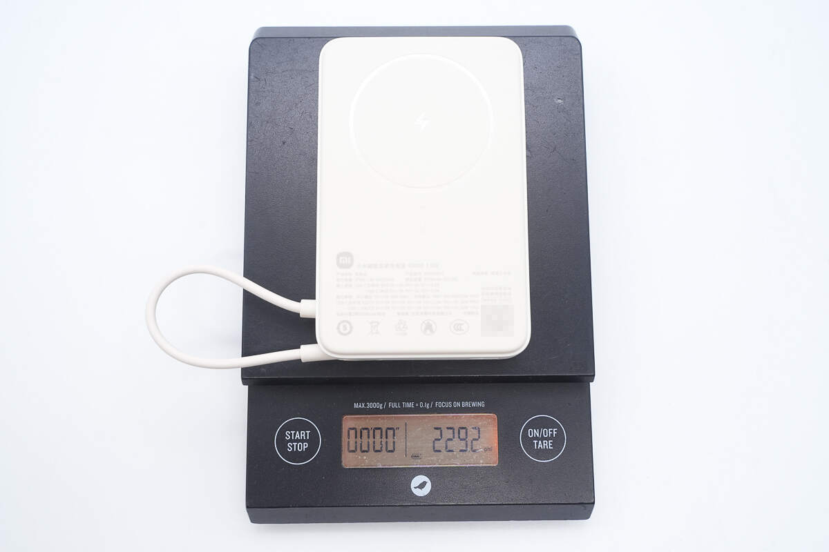
The weight is about 229 g (8.078 oz).
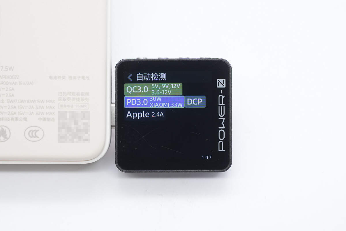
ChargerLAB POWER-Z KM003C shows that the USB-C port supports QC3.0, PD3.0, DCP, and Apple 2.4A charging protocols, as well as Xiaomi’s proprietary 33W protocol.
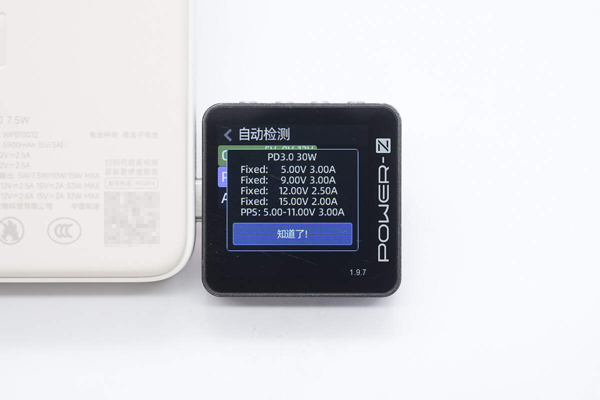
And it has four fixed PDOs of 5V3A, 9V3A, 12V2.5A, and 15V2A, as well as one Xiaomi proprietary voltage range of 5-11V3A.
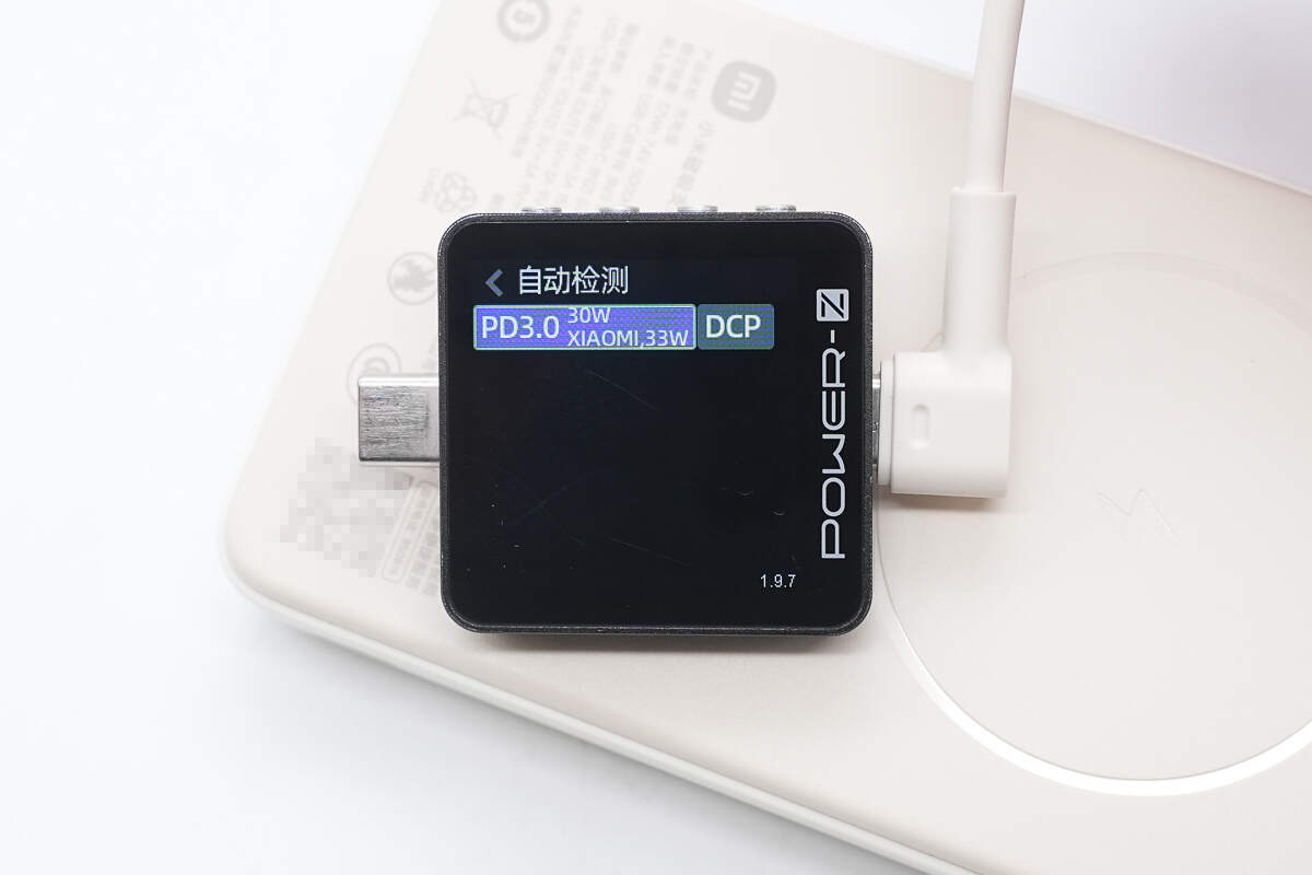
The USB-C cable supports PD3.0 and DCP charging protocols, as well as Xiaomi’s proprietary 33W protocol.
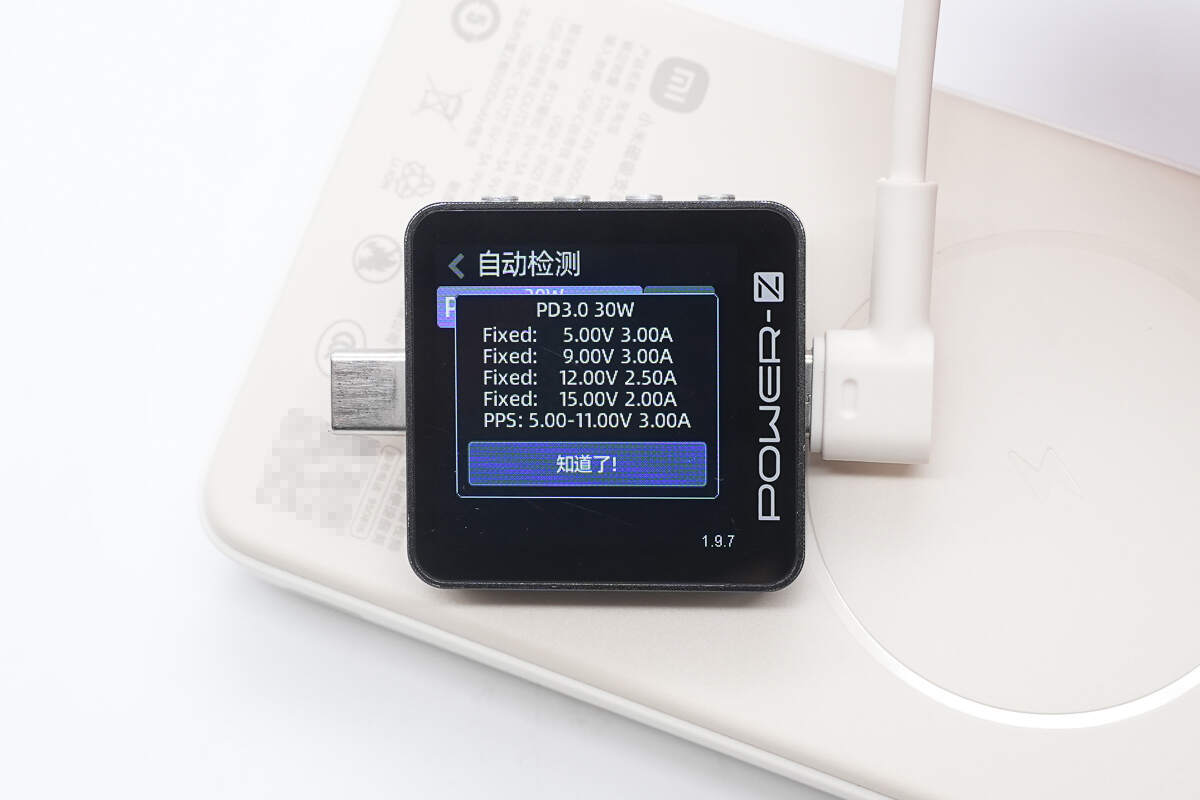
The PDO message display matches that of the USB-C port.
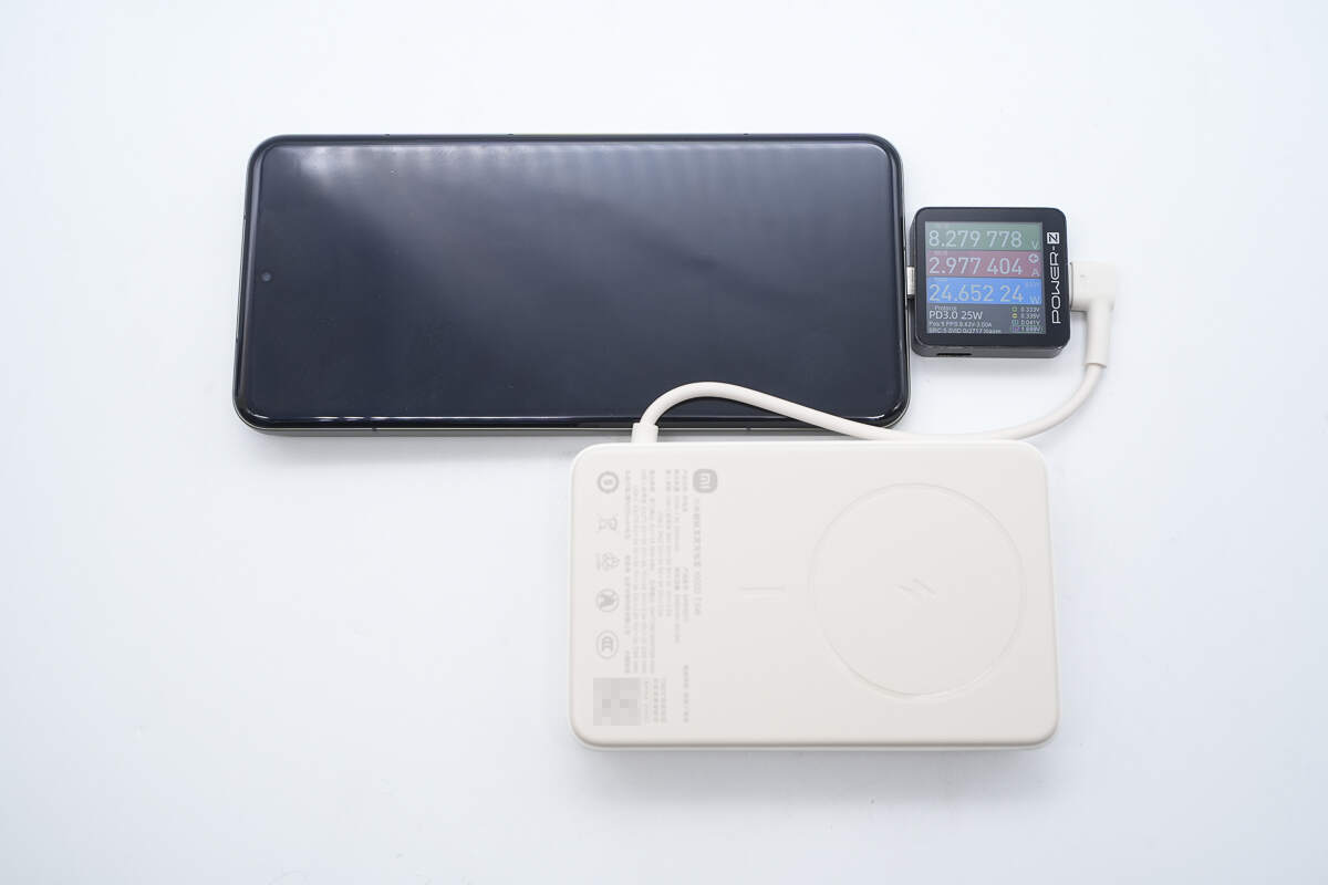
When charging the Xiaomi 15 Pro via USB-C cable, the power is about 24.65W.
Teardown
Next, let's take it apart to see its internal components and structure.
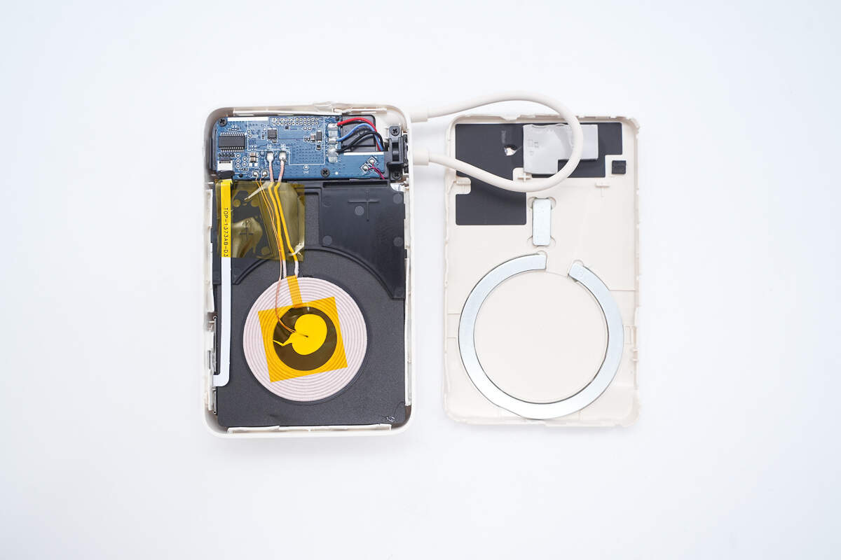
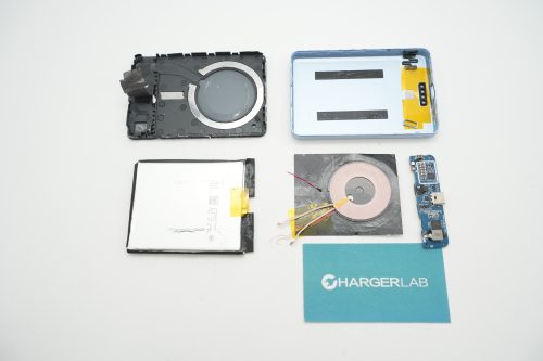
Open the snap-fit case by releasing the clips.
The area corresponding to the PCB has heat-dissipating copper foil and thermal pads.
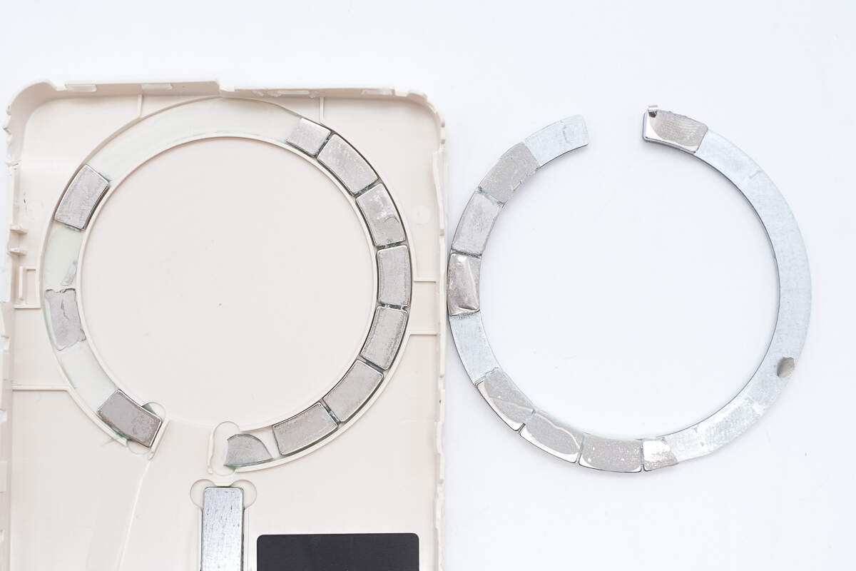
The magnetic ring is embedded in a groove and consists of 17 N52H magnets.
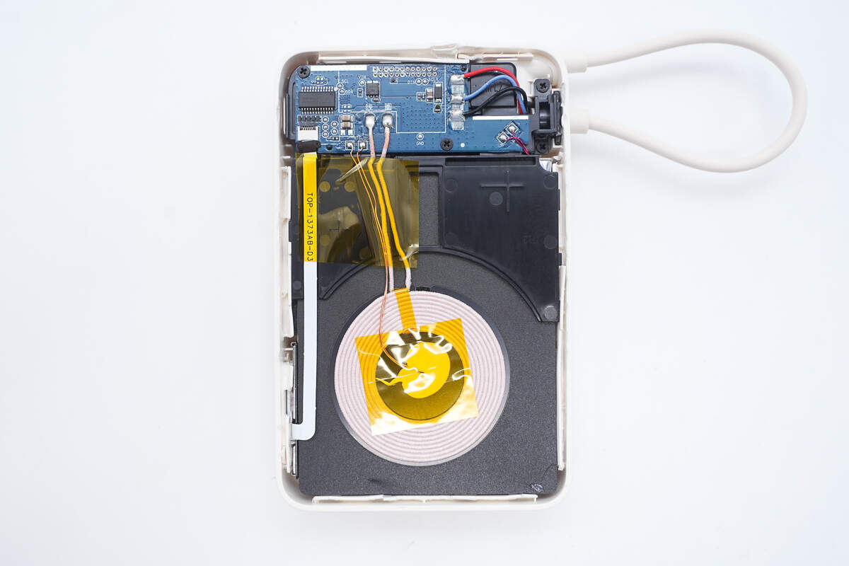
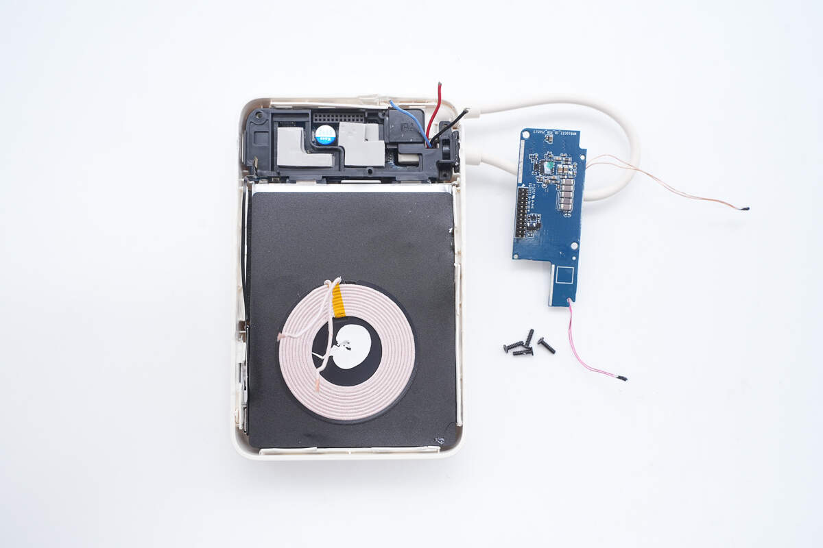
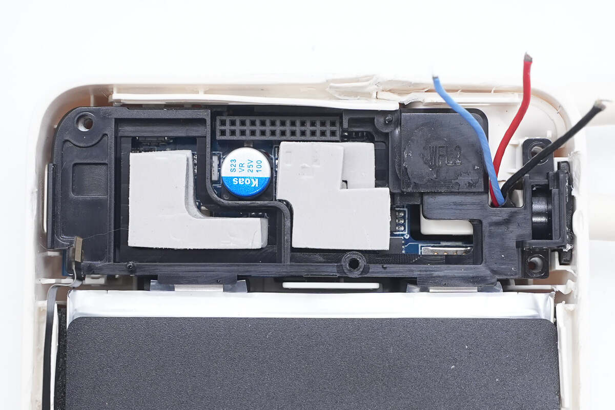
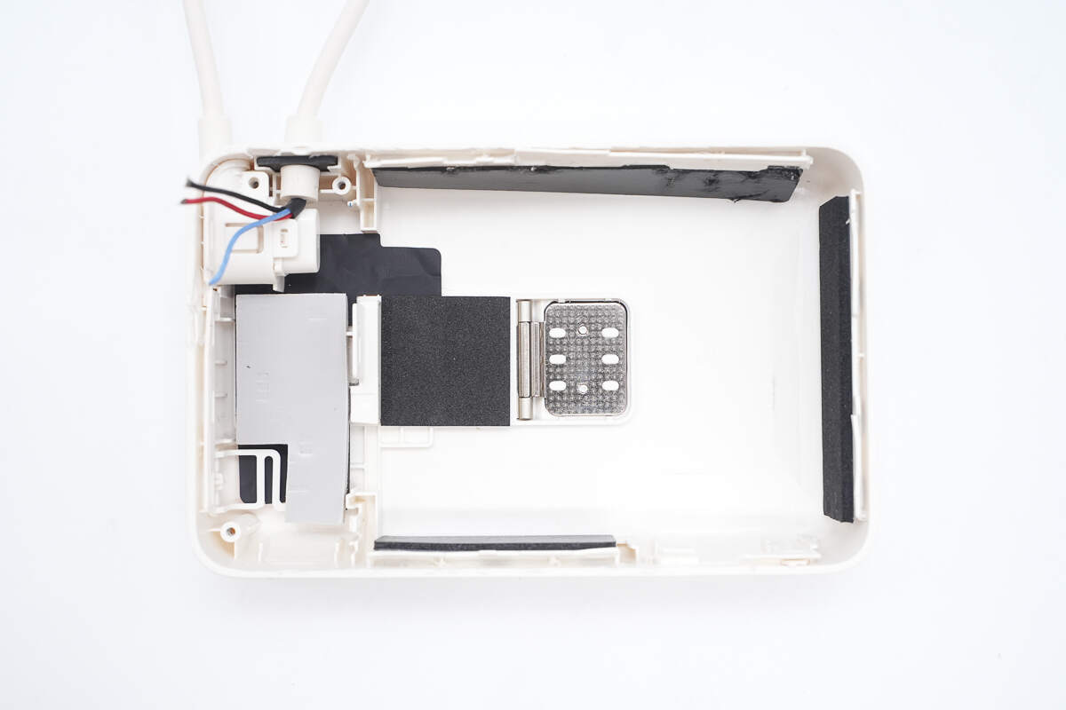
The other half of the casing contains the PCBa module, two thermistors, and the wireless charging coil. The PCBa module is secured with screws.
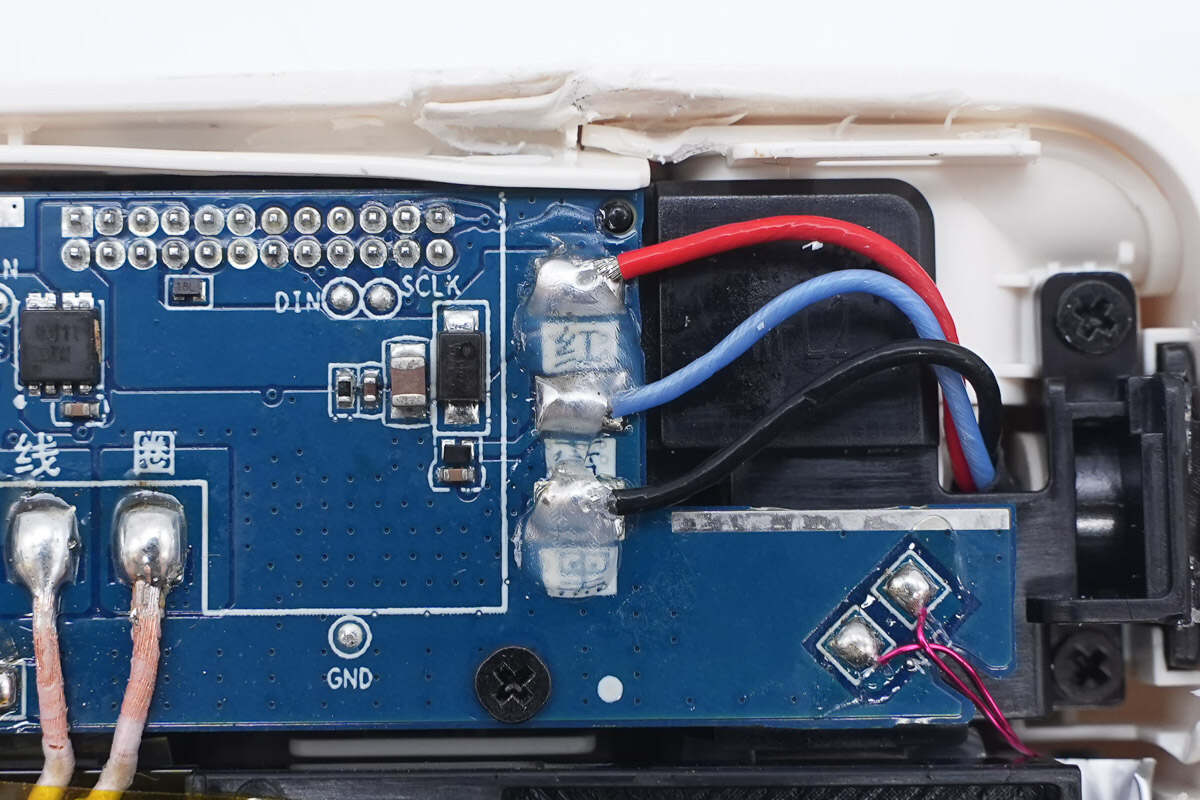
The USB-C cable solder joints are sealed with glue for protection.
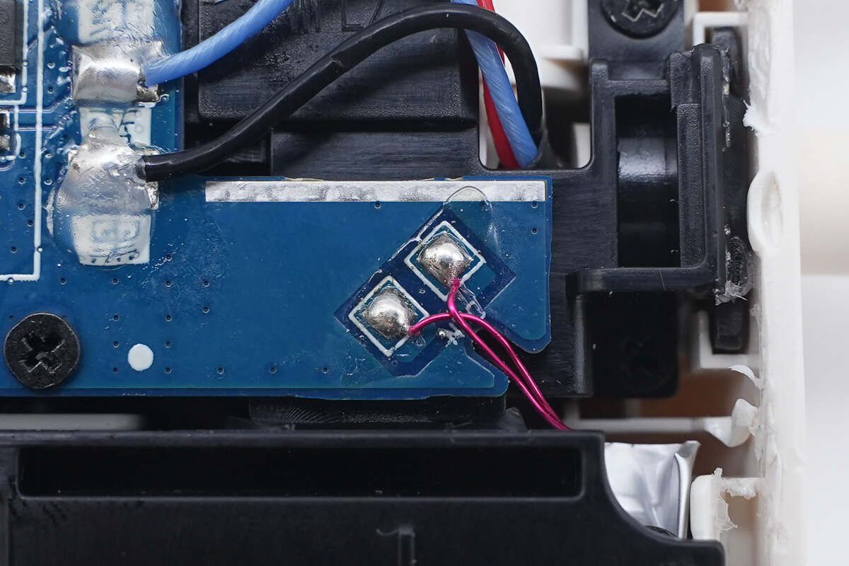
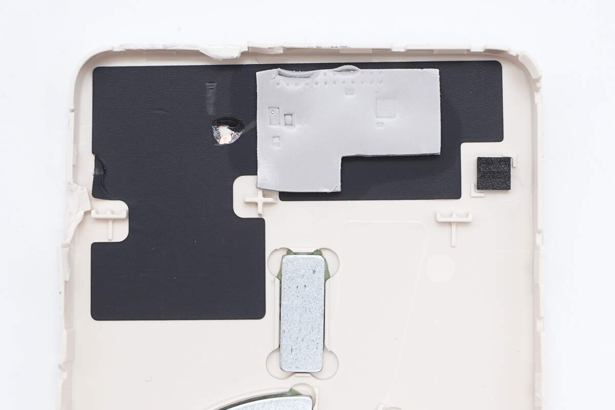
The thermistor in the bottom right corner is used to monitor the battery cells' temperature.
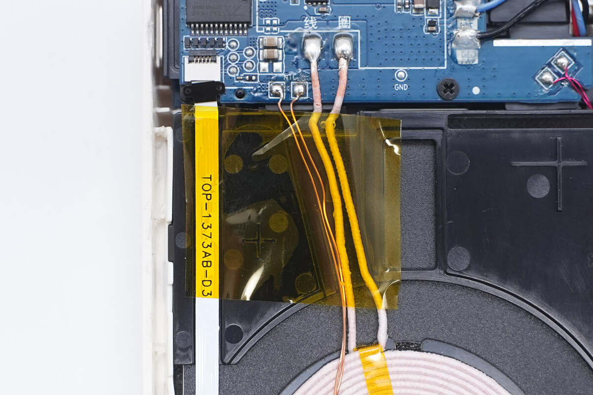
The other thermistor and the wireless charging coil are soldered to the PCB. The LED display connects to the PCB via a detachable ribbon cable, all secured with high-temperature insulating tape.
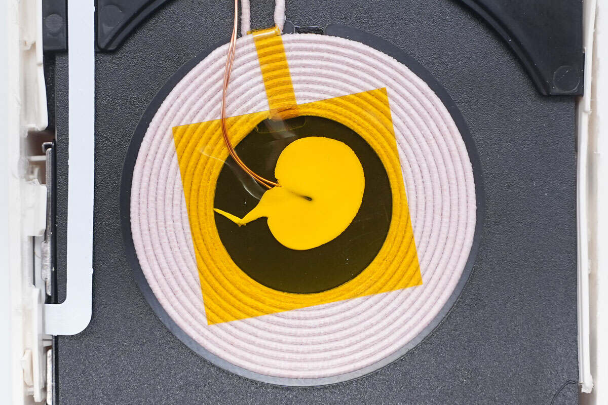
The second thermistor monitors the temperature of the charging coil; it is reinforced with glue and covered with high-temperature tape.
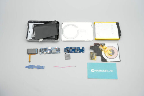
Remove the screws to take out the PCB, then separate the PCB from the coil.
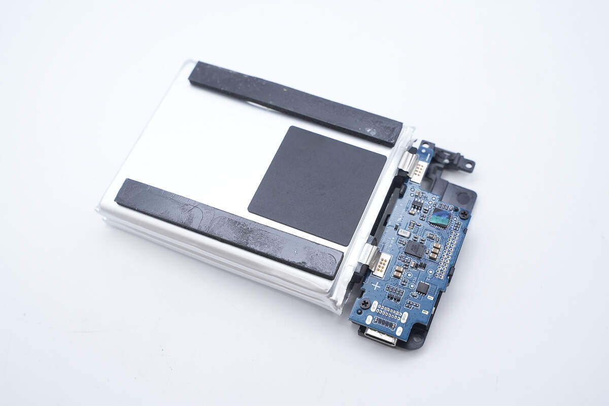
The PCBA module features a dual-layer design. The two PCBs are connected via pin headers with a plastic spacer between them. The lower PCB is covered with thermal pads.
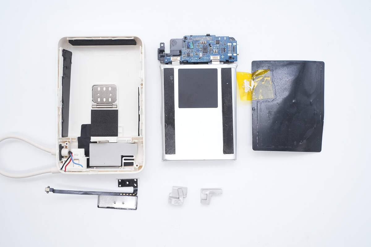
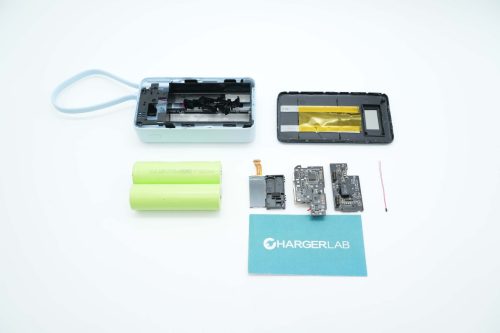
Remove the lower PCB and the battery cells.
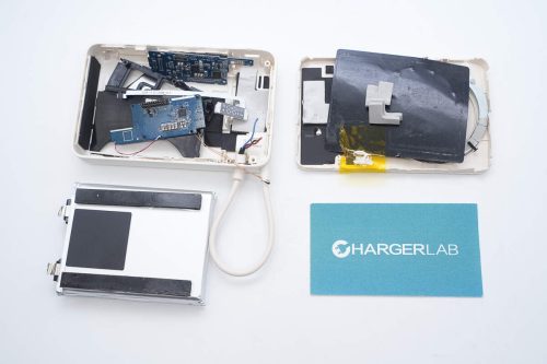
The inside of the casing also contains thermal pads and heat-dissipating copper foil.
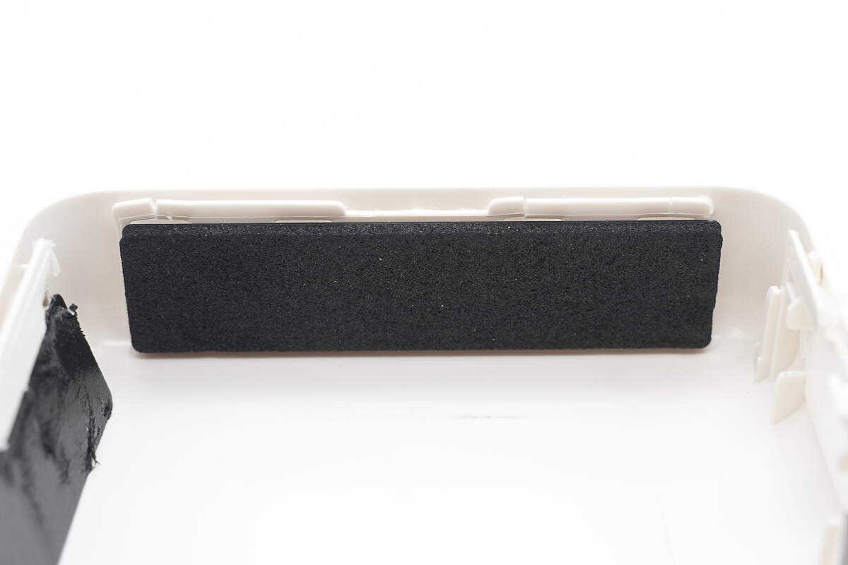
There is cushioning foam attached to the side to protect the battery cells.
Cushioning foam pads are attached to the bottom of the battery cells.
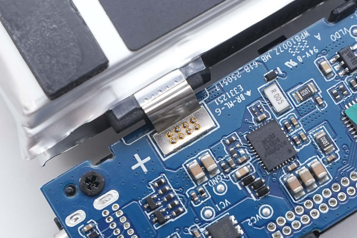
The battery cells are connected to the lower PCB via spot welding.
The lower PCB is secured to the plastic bracket with screws.
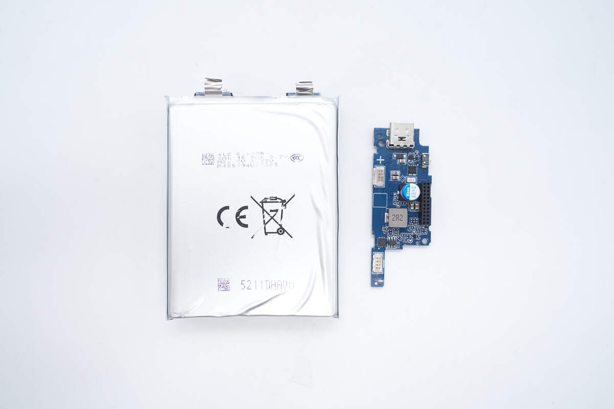
Separate the battery cells from the PCB.
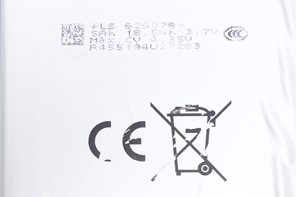
The two battery cells are from LS, model 626078, with a rated voltage of 3.7V, a charge limit voltage of 4.35V, a capacity of 5Ah, and an energy of 18.5Wh. They have passed both CCC and CE certifications.
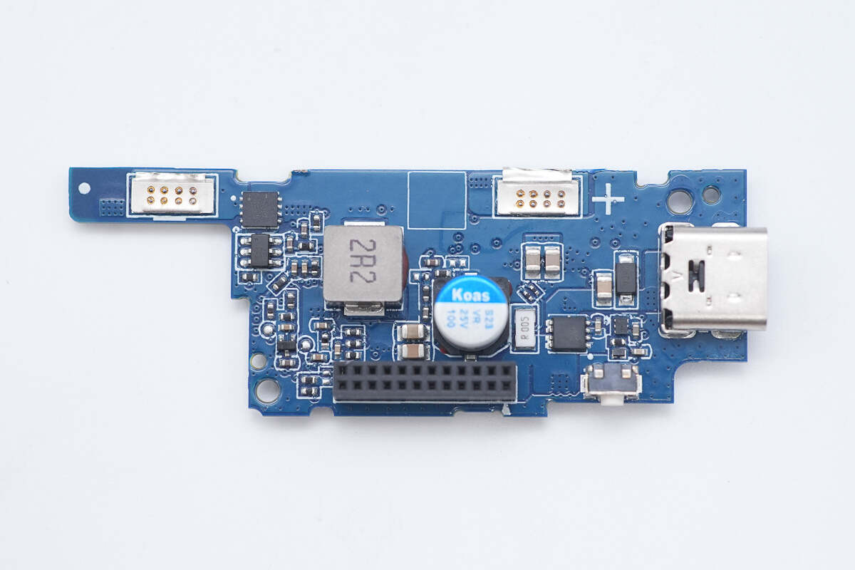
The front side of the lower PCB features a battery protection chip, a battery protection MOSFET, a buck-boost inductor, a solid capacitor, and VBUS MOSFETs.
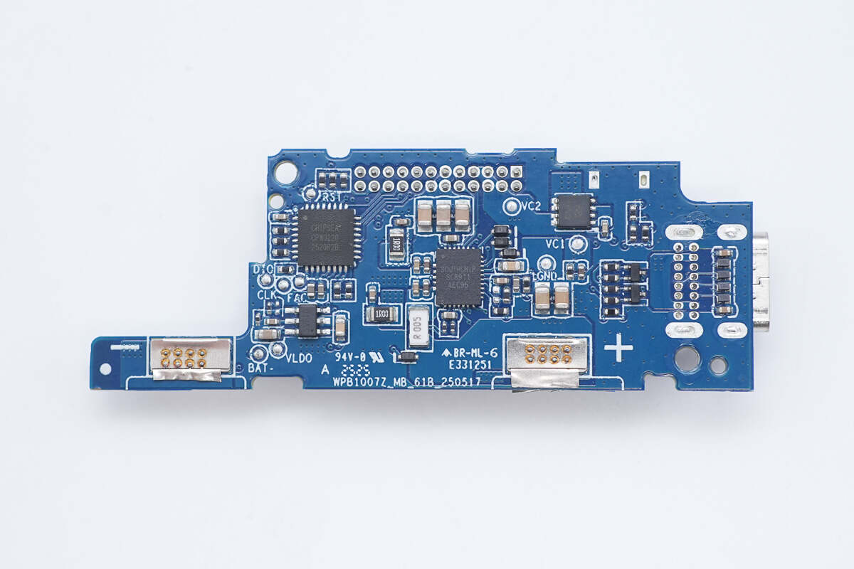
The back side houses a synchronous buck-boost converter, an interface controller, and VBUS MOSFETs.
The front side of the upper PCB contains the wireless charging master control chip and NPO resonant capacitors.
The back side features the LED display driver, VBUS MOSFETs, and two thermistors.
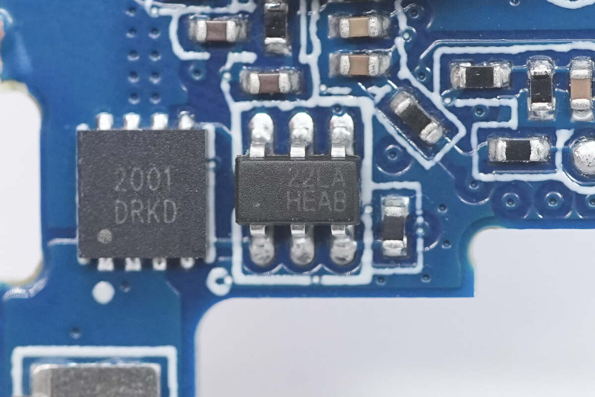
The battery protection chip is from iCM, model CM1025-LA. It is specifically designed for 2-series lithium/iron batteries and features built-in high-precision voltage and current detection circuits. It supports protection functions, including overcharge, over-discharge, overcurrent during discharge, short circuit, and overcurrent during charging detection.
Here is the information about iCM CM1025-LA.
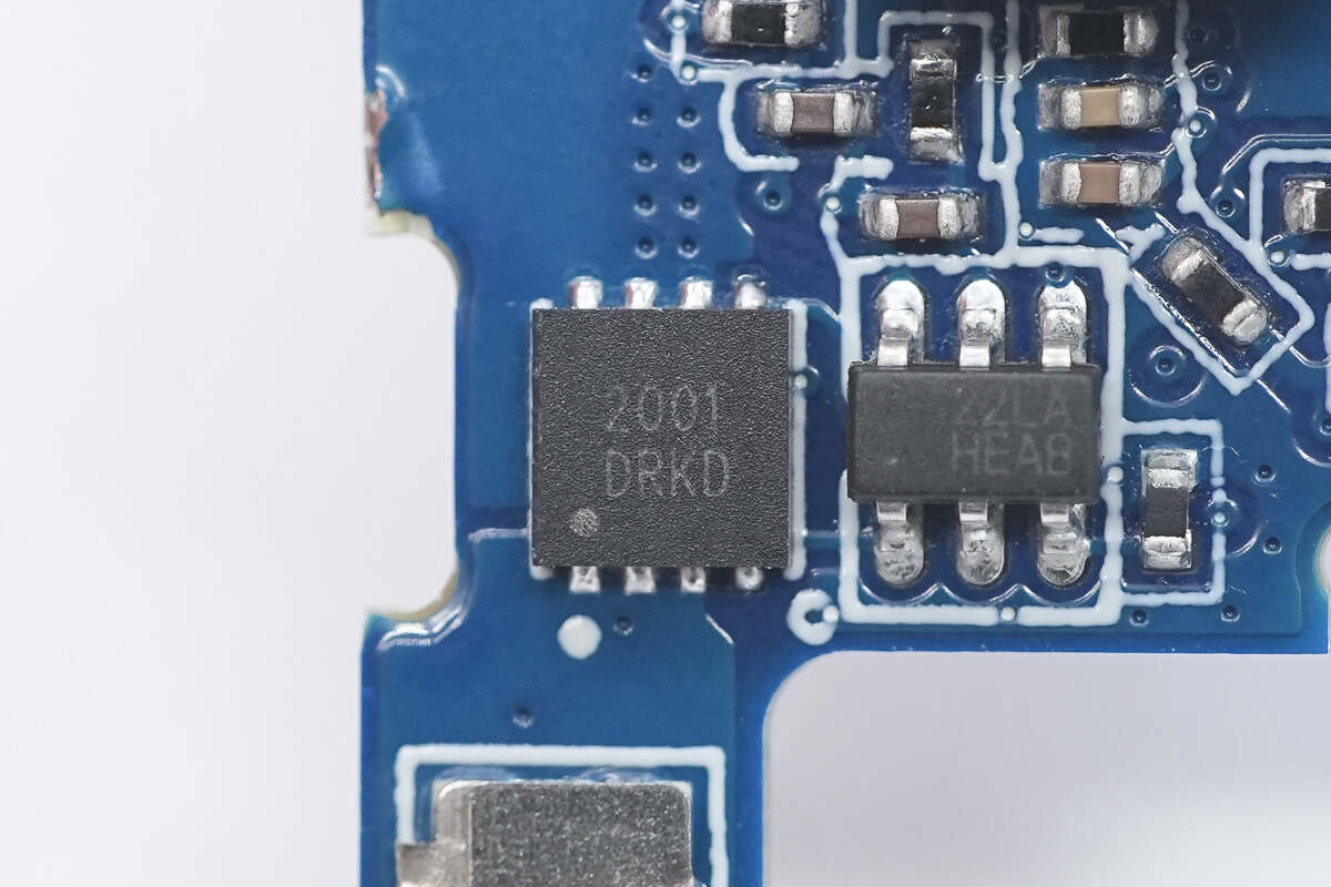
The battery protection MOSFET is marked with 2001.
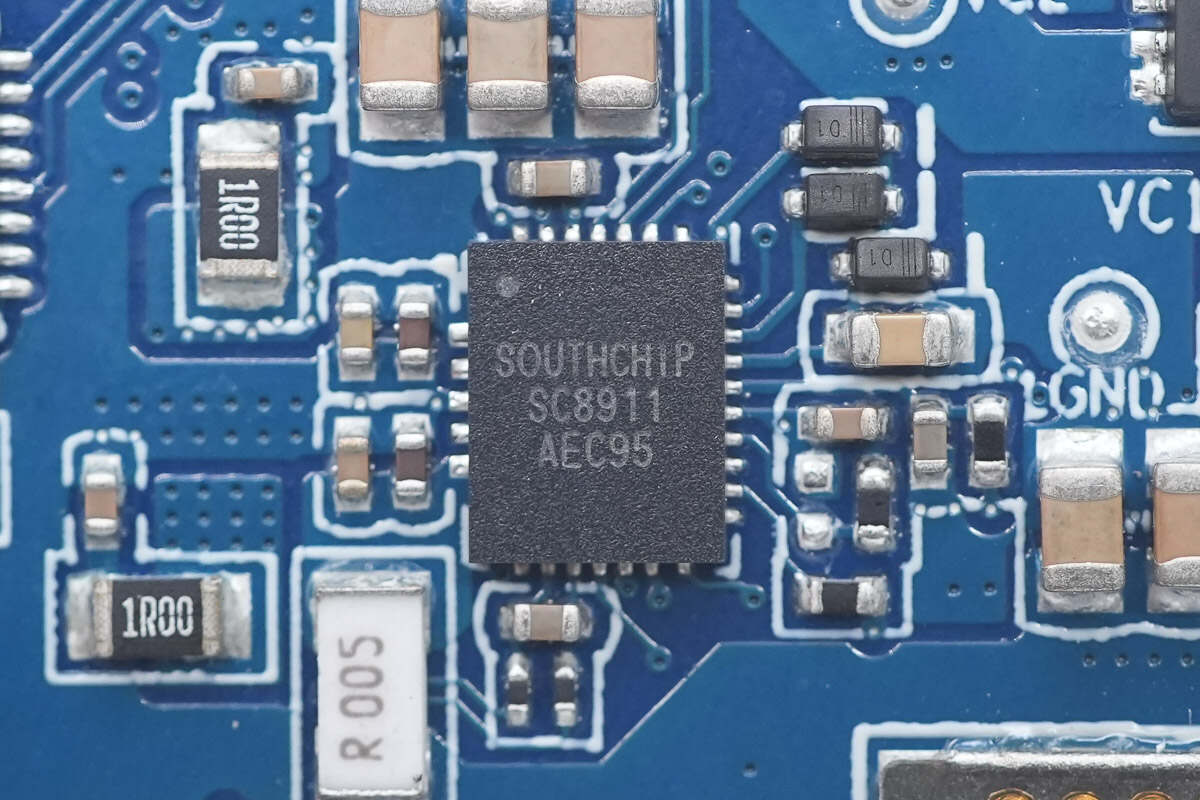
The synchronous buck-boost converter is from SouthChip, model SC8911. It supports buck, boost, and buck-boost modes during forward charging or reverse discharging operations. It manages charging for 2-cell lithium-ion and lithium iron phosphate batteries, supporting trickle charge, pre-charge, constant current charge, constant voltage charge, and automatic termination. In discharge mode, it offers a wide output voltage range from 3.3V to 21V. Through an I2C interface, charging/discharging modes can be easily configured, allowing flexible programming of charging current, charging voltage, input voltage regulation, input current limit, OTG output voltage regulation, current limit, and other parameters.
The SC8911 also provides various monitoring functions, including input current/voltage, battery current/voltage, junction temperature, and output current for three ports. It supports comprehensive protection features such as port and battery overvoltage protection, output overvoltage protection, battery and output undervoltage protection, cycle-by-cycle current limit, and thermal shutdown protection. It is housed in a 4mm × 5mm QFN-27 package.

Close-up of the 2.2μH buck-boost inductor.
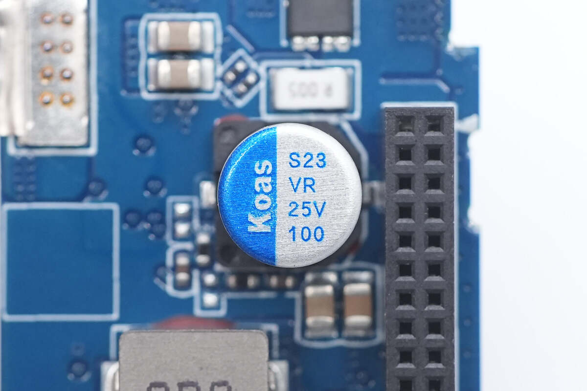
The solid capacitor is from Koshin. 25V 100μF.
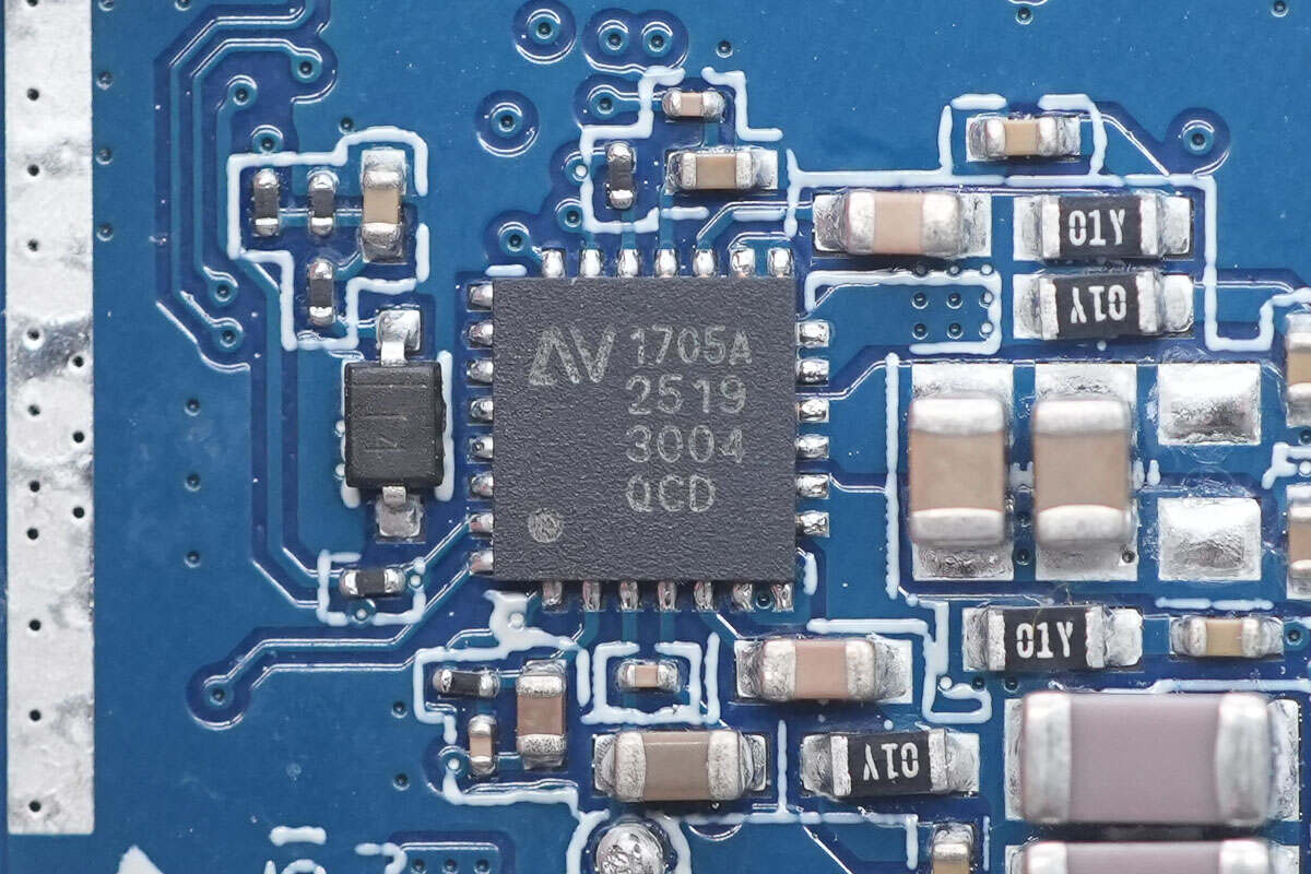
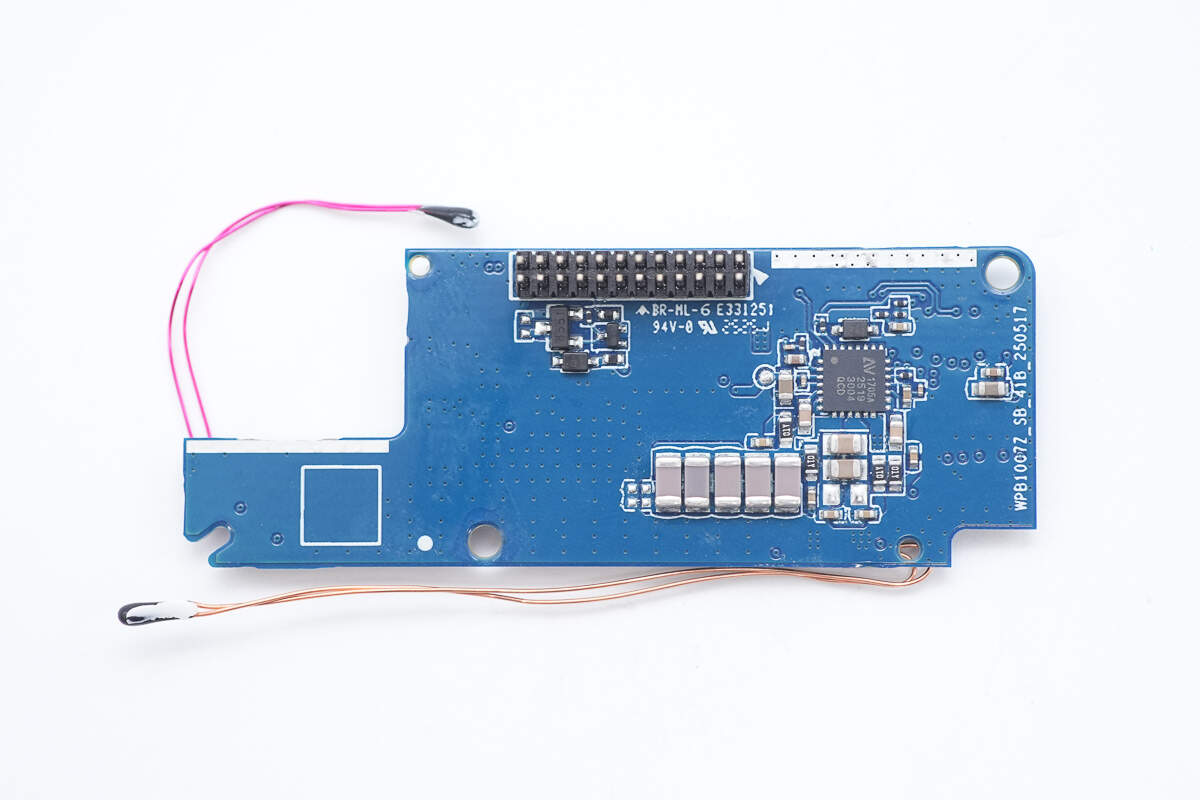
The wireless charging master control chip is from NuVolta, model NU1705A. It integrates a full-bridge power stage architecture suitable for a wide frequency range and a 32-bit MCU core. The power system includes all key modules: high-efficiency power MOSFETs, low-EMI FET drivers, bootstrap circuits, integrated 4.8V/1.8V LDO regulators, and lossless current sensing technology.
Its patented current sensing circuit provides precise current measurements used for FOD, power measurement, in-band communication, quality factor (Q) detection, and digital demodulation. The chip features multiple protection mechanisms: input undervoltage lockout, overvoltage protection, overcurrent protection, a unique Juggle Protection dynamic circuit, and thermal shutdown protection, greatly enhancing the overall system reliability. It comes in a 4mm × 4mm QFN package.
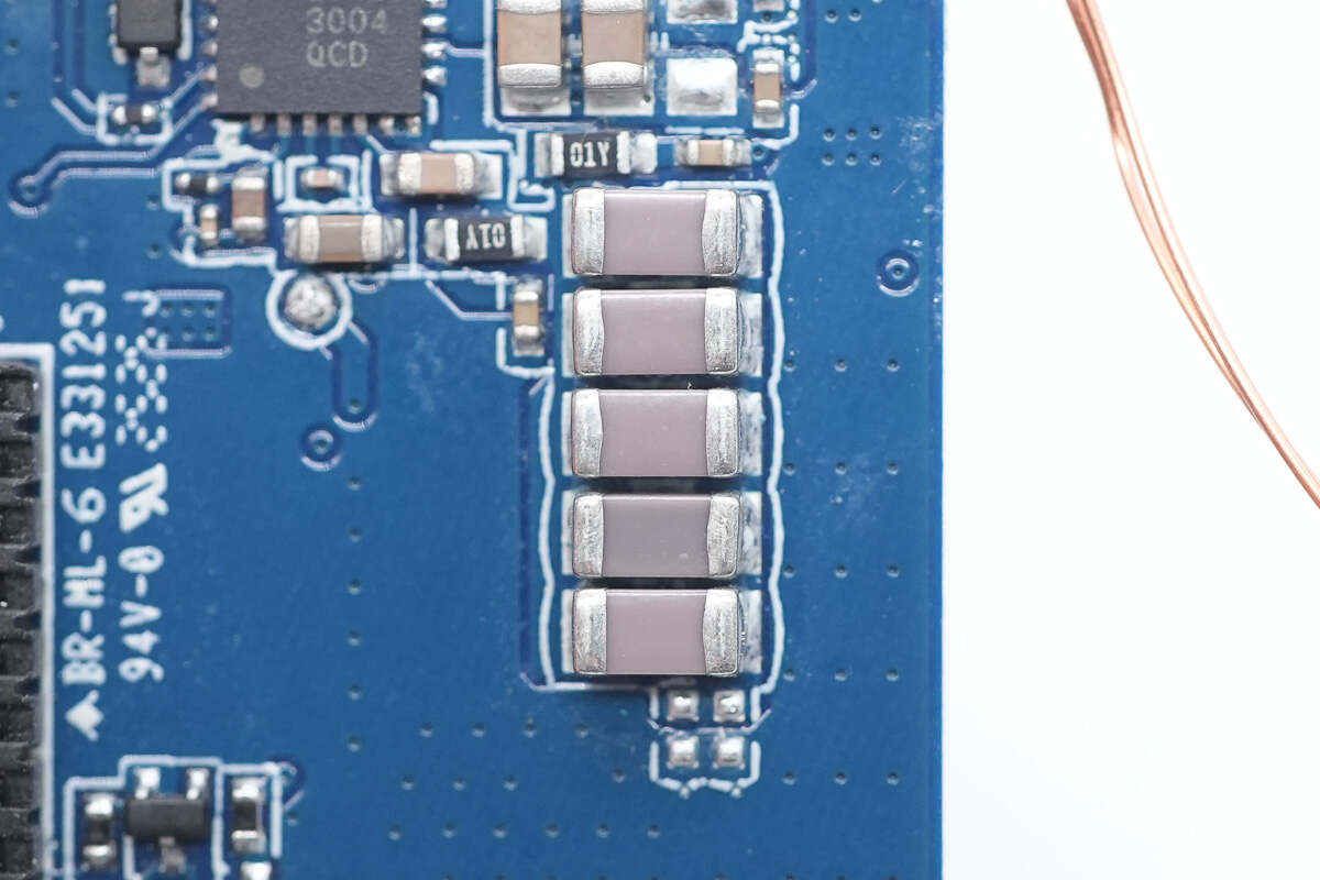
Close-up of NPO resonant capacitors.
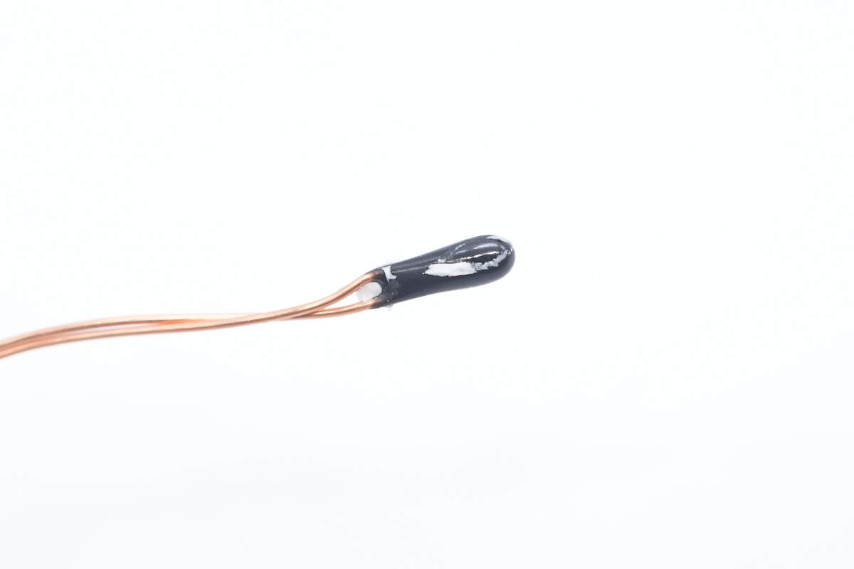
Close-up of the thermistor used for coil temperature monitoring.
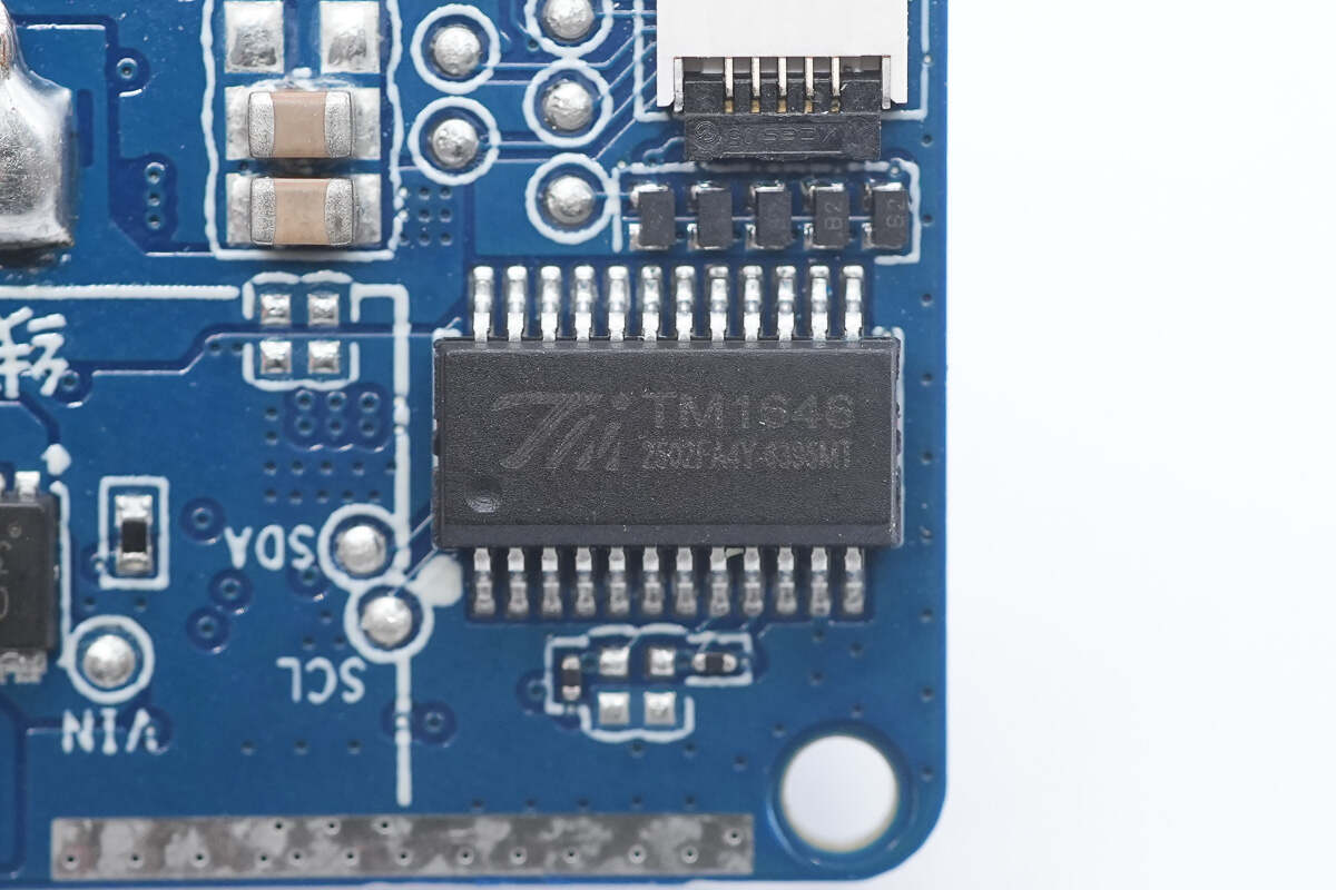
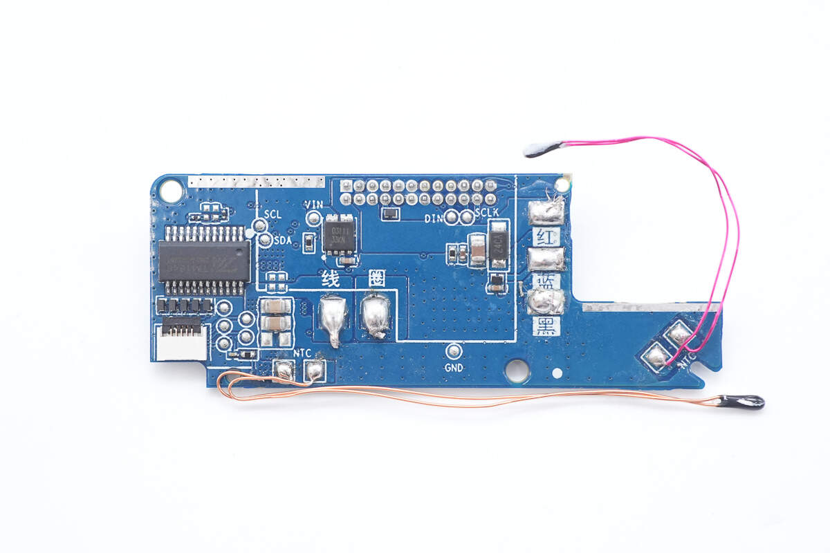
The TM TM1646 is used as the display driver for the display.
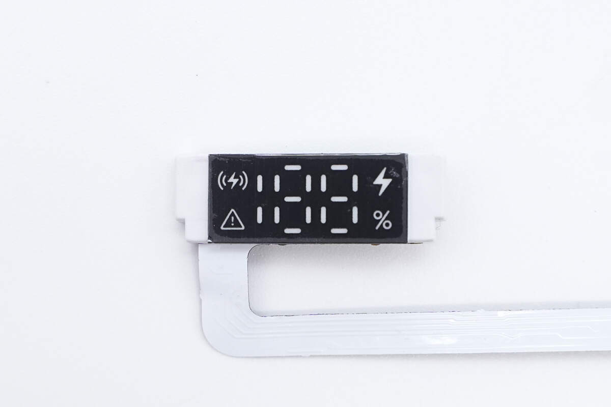
Close-up of the LED digital display.
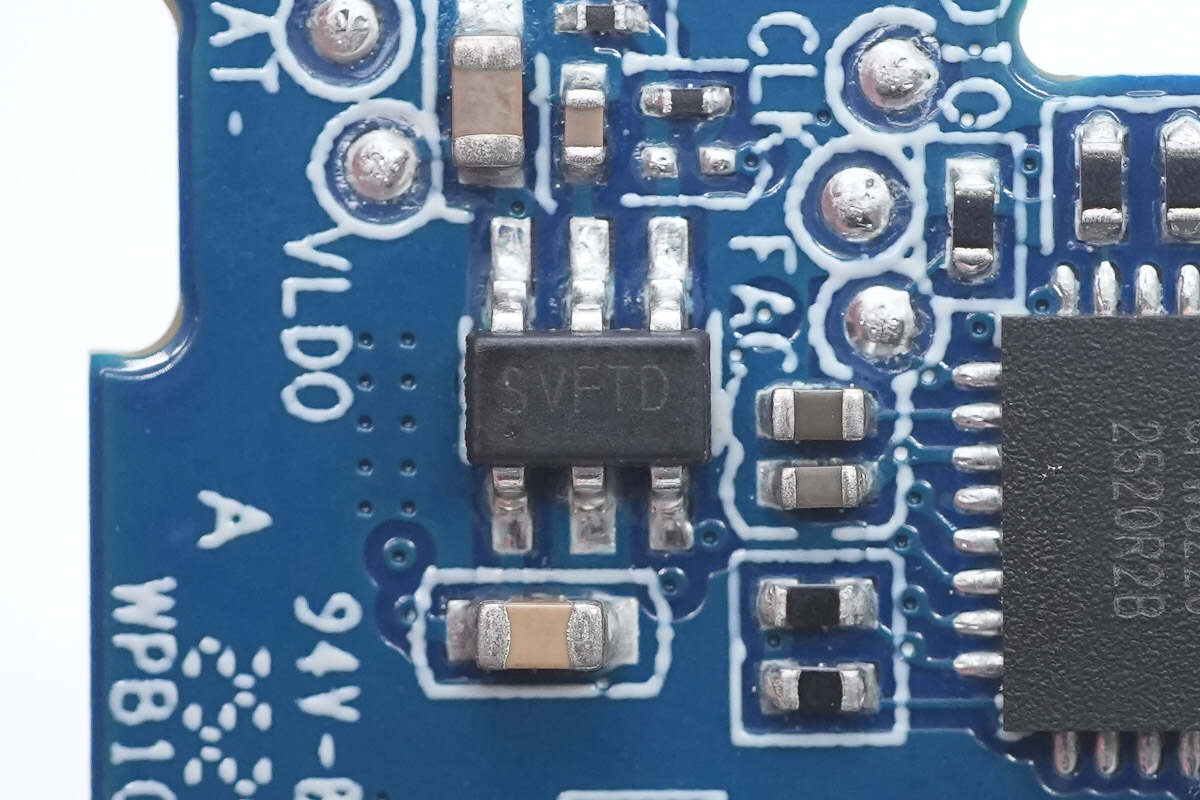
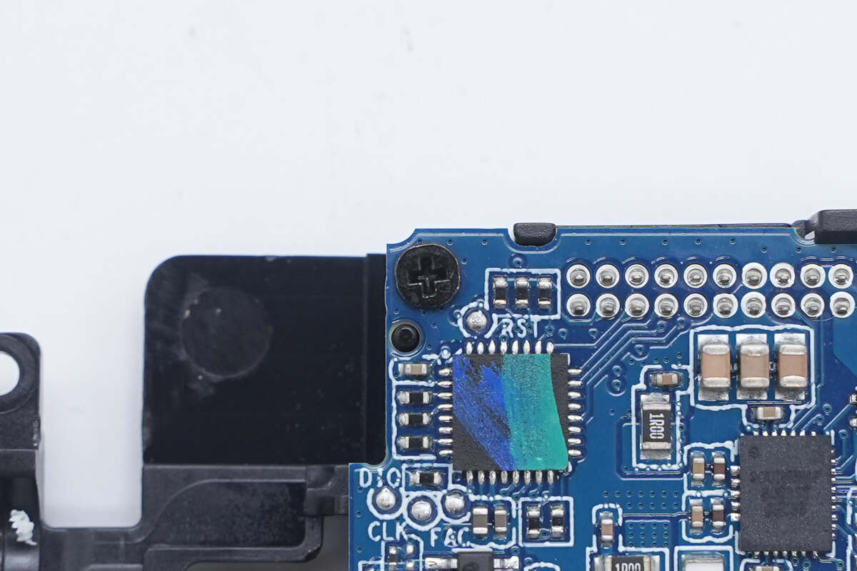
This is a chip marked with "SVFTD."
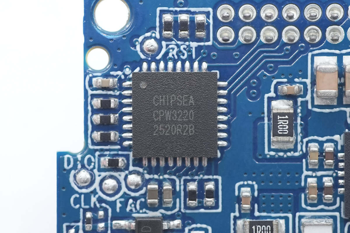
The Chipsea CPW3220 series is a USB Type-C and USB PD controller designed for bidirectional battery applications. It integrates two independent Type-C CC and USB PD functions, a load switch driver, and USB BC1.2 support. Additionally, it supports multiple fast-charging protocols for various smartphones, enhancing charging compatibility with end devices. This chip is suitable for use in power banks, power tools, and other fields, enabling a dual Type-C port solution with a single chip.
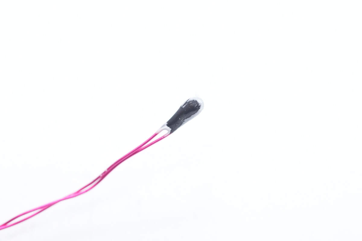
Close-up of the thermistor used for battery cell temperature monitoring.
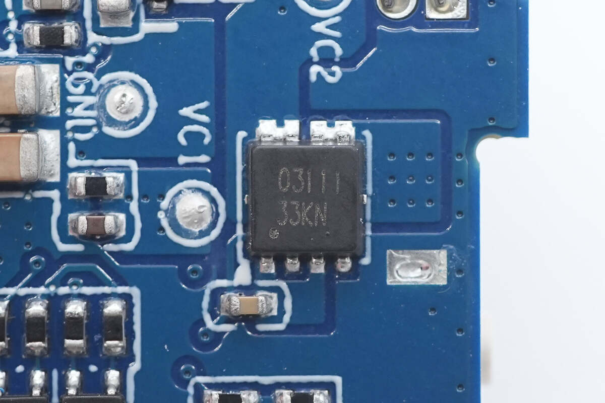
Close-up of the VBUS MOSFET marked with 03111.
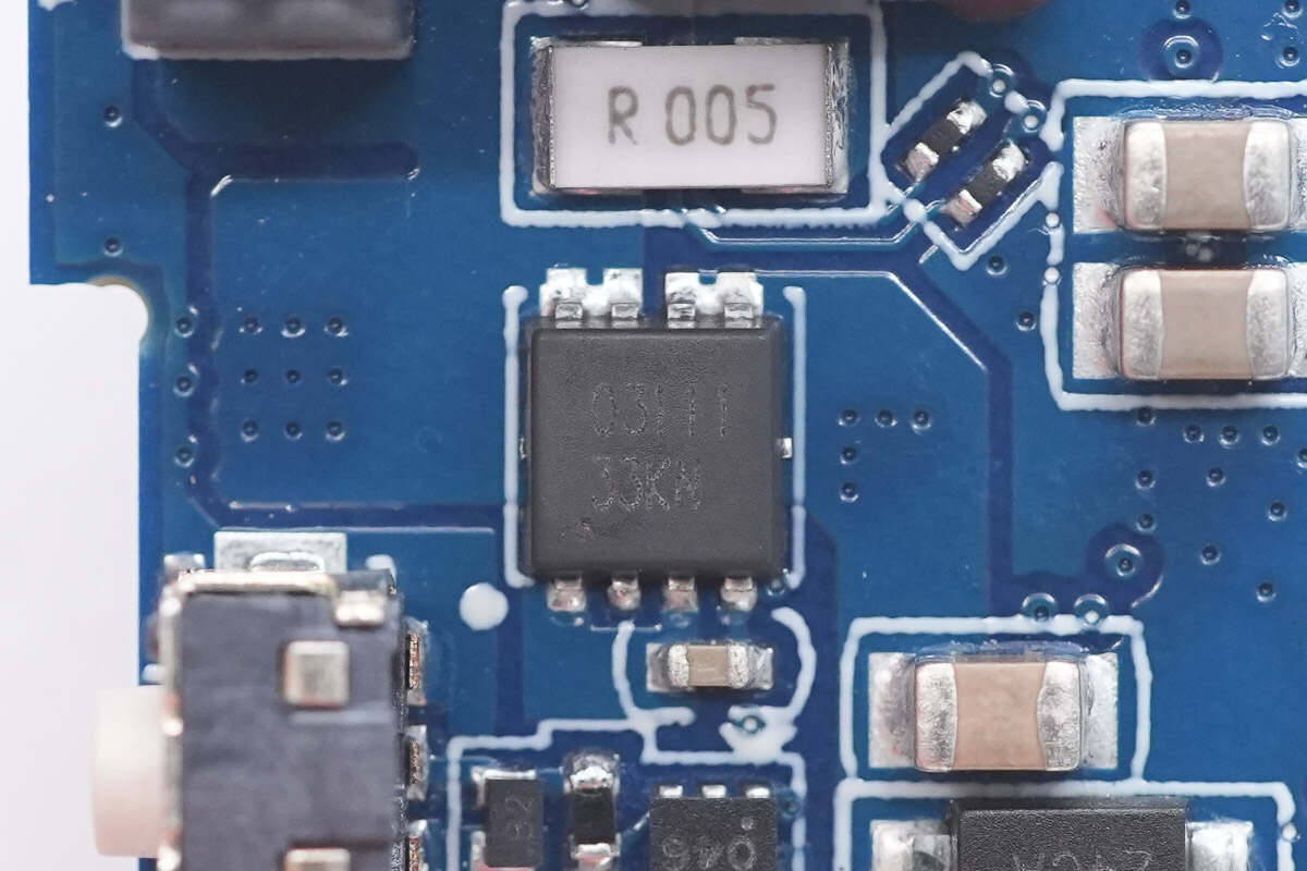
The other VBUS MOSFET has the same part number.
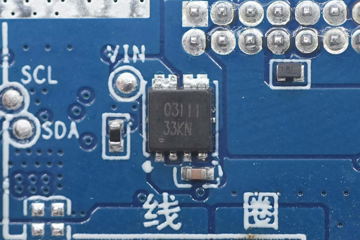
The third VBUS MOSFET also has the same part number.
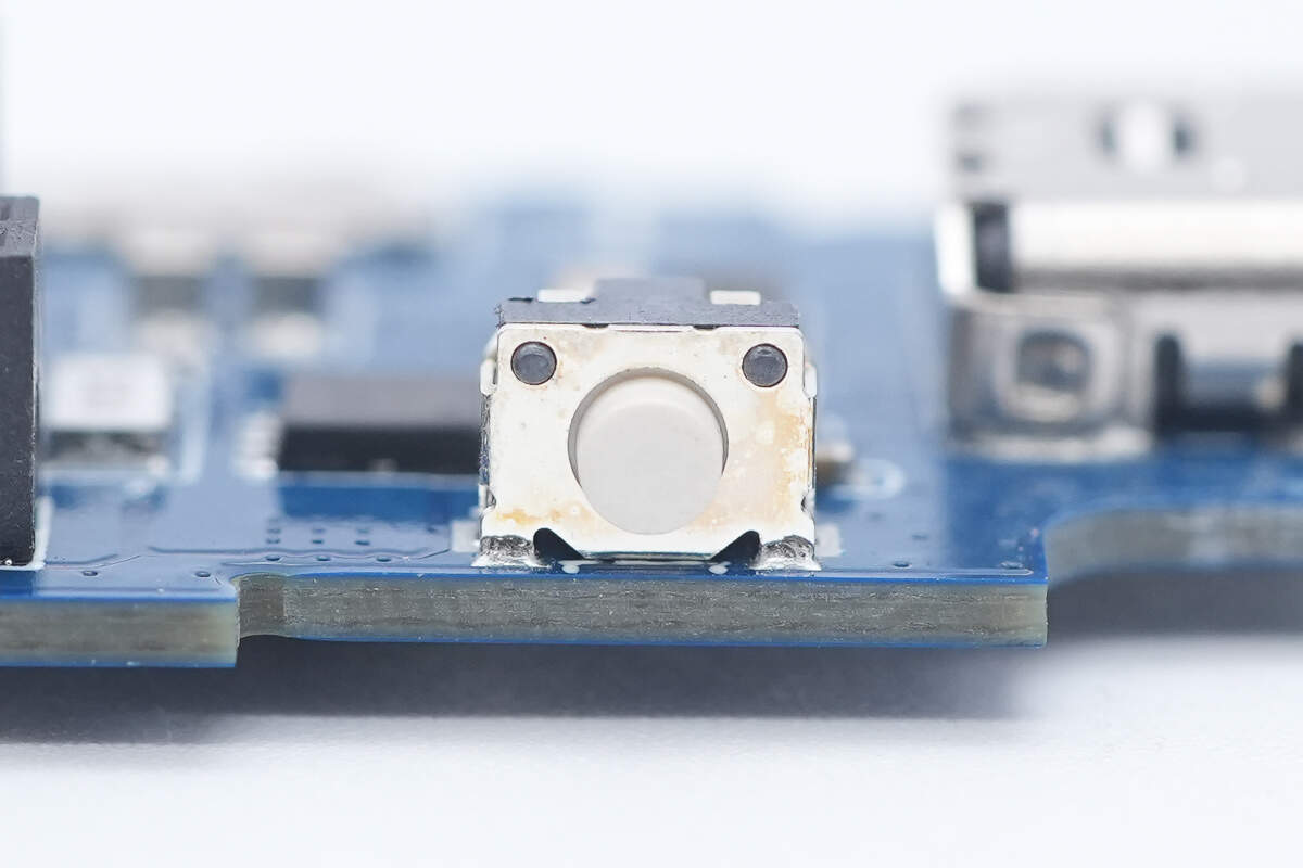
Close-up of the power button.
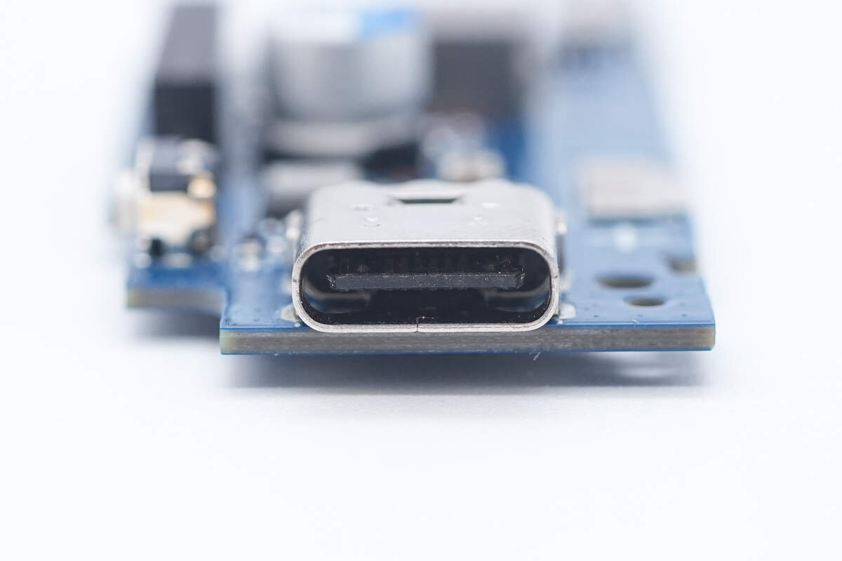
The USB-C socket is soldered using through-hole technology.

Well, those are all components of the Xiaomi 10000mAh 7.5W Magnetic Stand Power Bank.
Summary of ChargerLAB
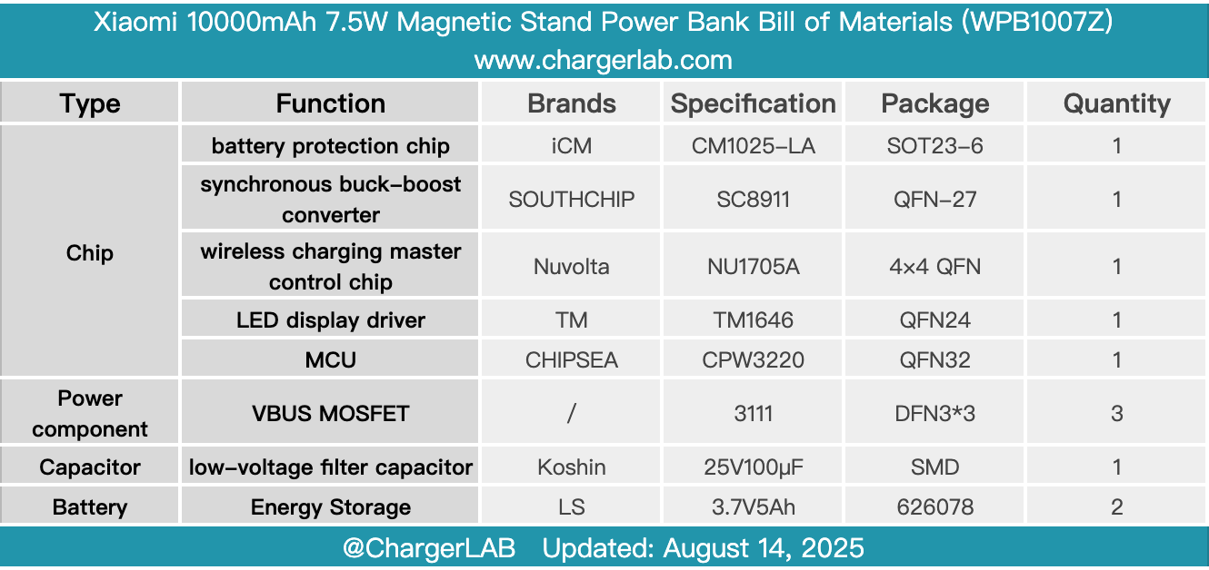
Here is the component list of the Xiaomi 10000mAh 7.5W Magnetic Stand Power Bank for your convenience.
Its built-in USB-C cable is not only convenient to use but can also serve as a carrying strap. When powering your phone, it doesn’t block the camera, making it easy to charge while playing or taking photos and videos. The foldable metal stand and LED digital display further enhance its practicality. Supporting 15W wireless output and 33W wired output, it meets the fast-charging needs of Xiaomi devices as well as brands like Apple.
After taking it apart, we found that it uses two LS polymer lithium battery cells, which have passed CCC certification and are protected by the iCM CM1025-LAE chip. The PCBA module features a dual-layer design and employs the Chipsea CPW3220 MCU paired with the SouthChip SC8911 synchronous buck-boost converter to enable bidirectional fast charging for both the integrated cable and the USB-C port.
The NuVolta NU1705A highly integrated wireless charging solution enables wireless charging functionality. Both the coil and battery cells are equipped with thermistors for temperature monitoring. The PCBs feature thermal pads, and the casing is lined with heat-dissipating copper foils and thermal pads. The battery cells are protected with cushioning foam, reflecting reliable build quality.
Related Articles:
1. Teardown of RayNeo Magic Box 2 for AR Glasses (XRAC-BOX02CN)
2. Teardown of TECNO 45W Accessories Charger (U450TEC)
3. Teardown of Insta360 X5 Utility Fast Charge Case (CINSBAHM)