Introduction
We recently got the EcoFlow 230W Power Bank with Built-in Cable. Featuring a sleek and modern design, it boasts a vibrant 860-nit full-color HD display and enhanced smart interaction through seamless app connectivity. It is equipped with a 60cm retractable USB-C cable alongside three USB-C ports. It supports a combined output of up to 230W, including 100W bidirectional fast charging and 65W output.
Innovatively, it incorporates a pogo pin charging contact that enables 120W input when connected to the EcoFlow RAPID Pro 320W five-port desktop charging station. Below, we’ll take a closer look at the detailed design of this product.
Product Appearance
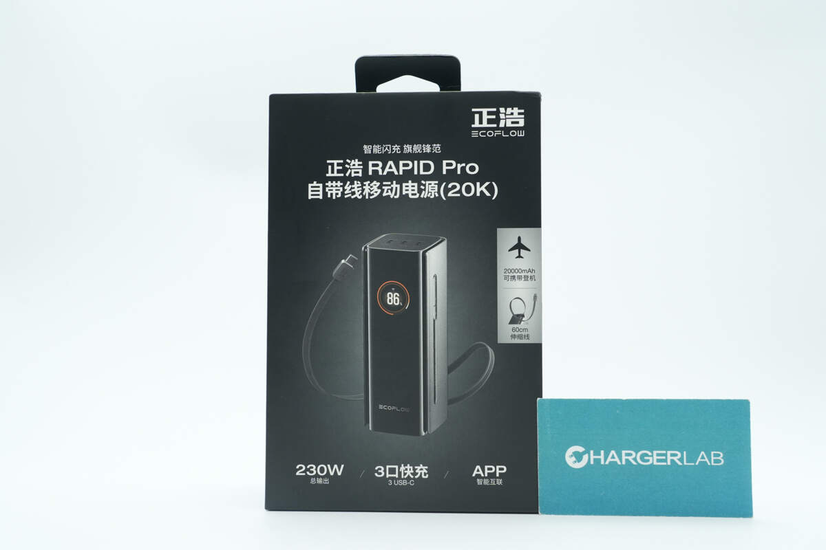
The front of the packaging features EcoFlow, the product name, its appearance, and key selling points.
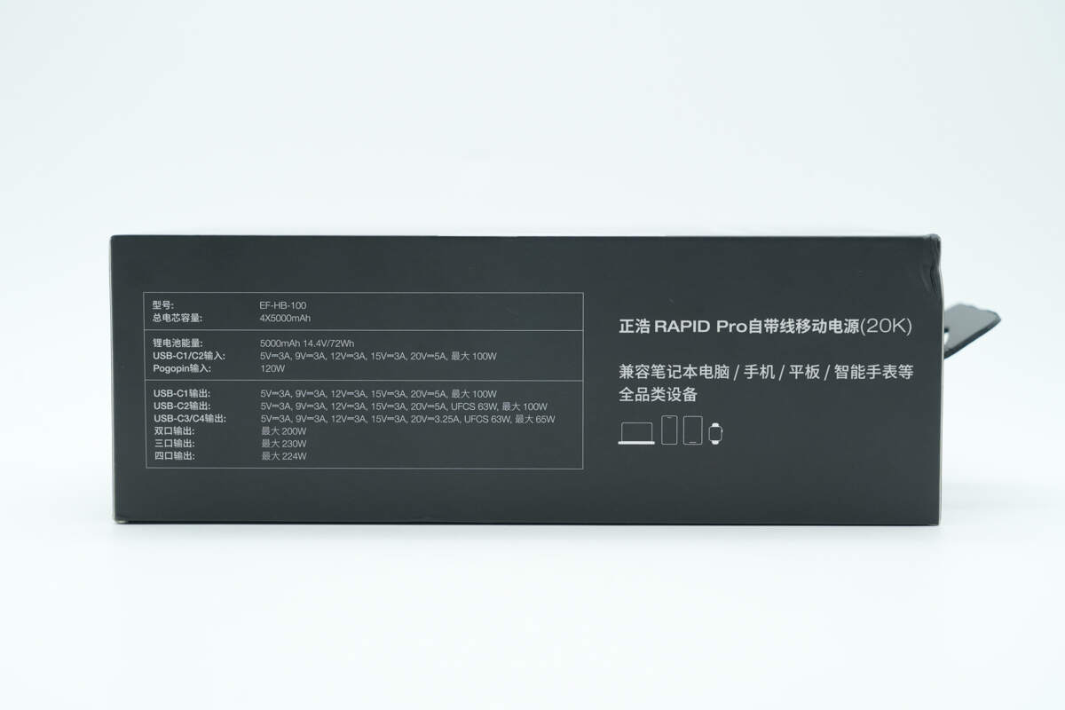
The side of the packaging displays the specifications and compatibility information for a wide range of devices, including laptops, smartphones, tablets, smartwatches, and more.

The back of the packaging showcases the product’s application scenarios and highlights its key selling points.
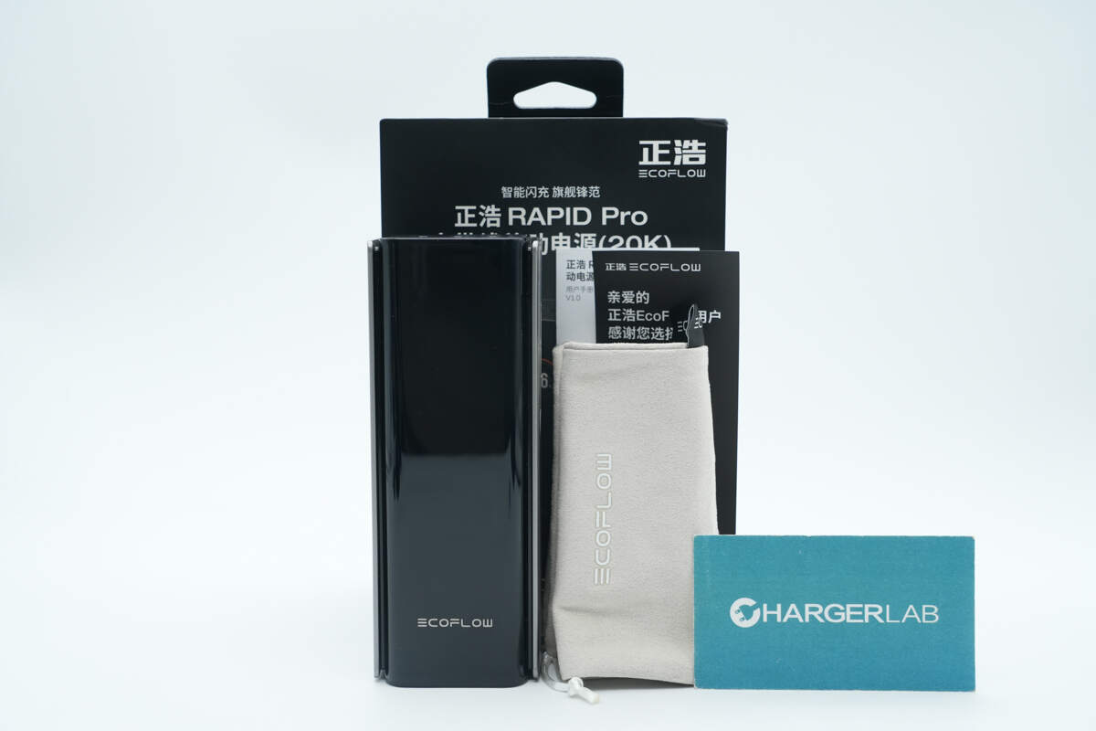
The package includes the power bank, storage pouch, user manual, and a thank-you card.
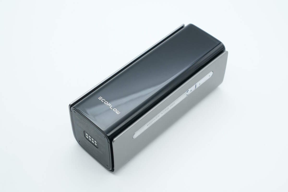
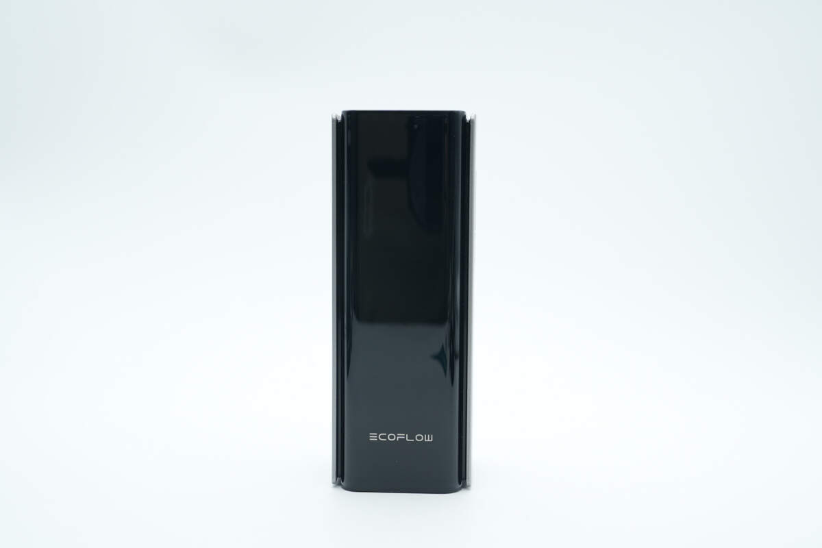
It features an obsidian glass-textured panel with a nested design, giving it a strong futuristic and high-tech appeal.
The panel shimmers with changing light angles, enhancing its premium texture.
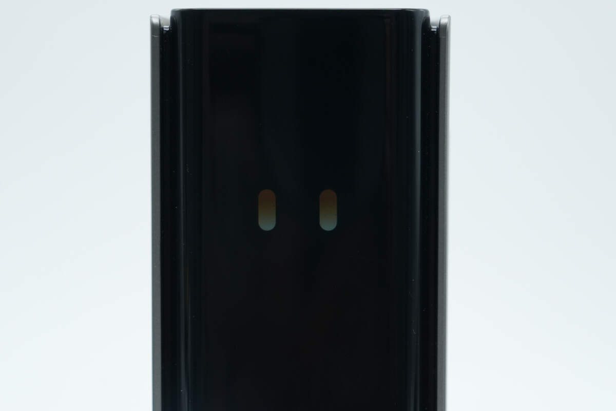
At the top is a hidden full-color smart display with 860 nits brightness, delivering a high-definition screen that elevates the smart interaction experience.
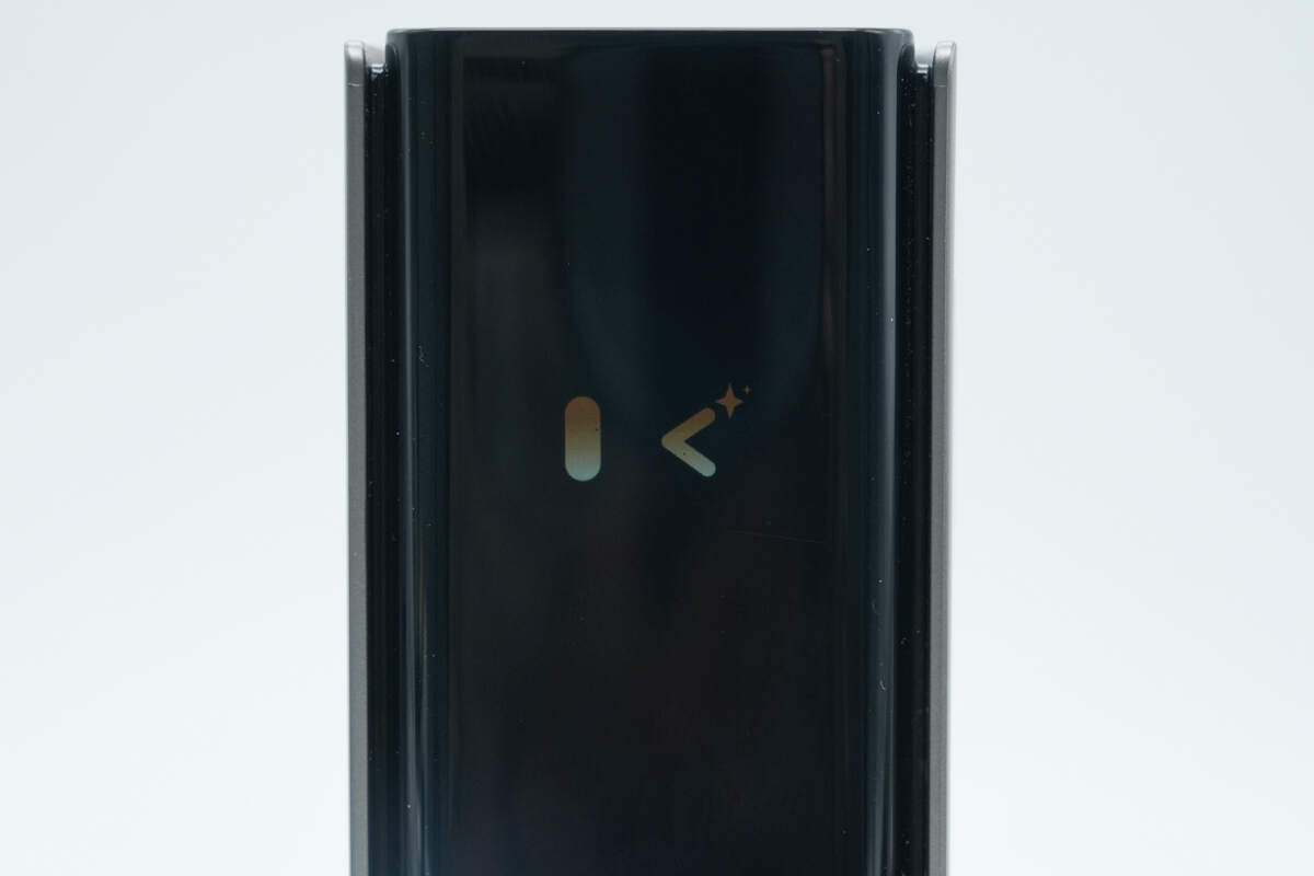
The display offers a variety of functional interfaces, including the ability to show personalized and engaging emojis.
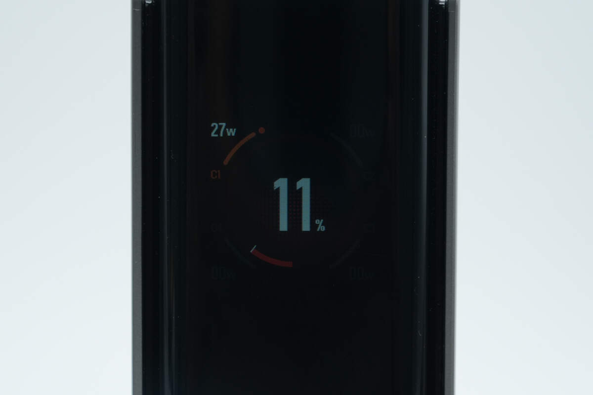
It also shows the remaining battery level, the status of the four USB-C ports, and real-time input and output power.
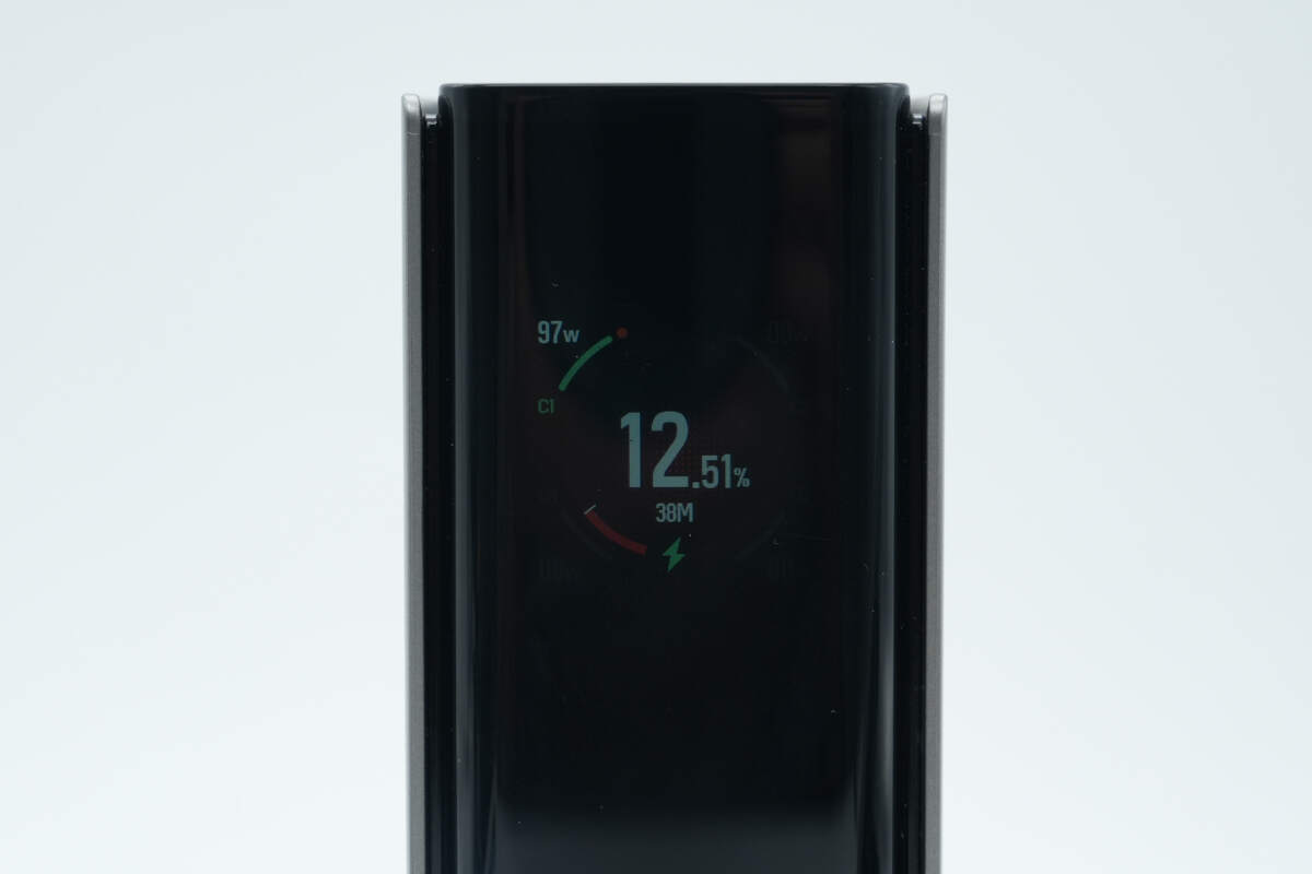
Charging and discharging statuses are distinguished by different colors.
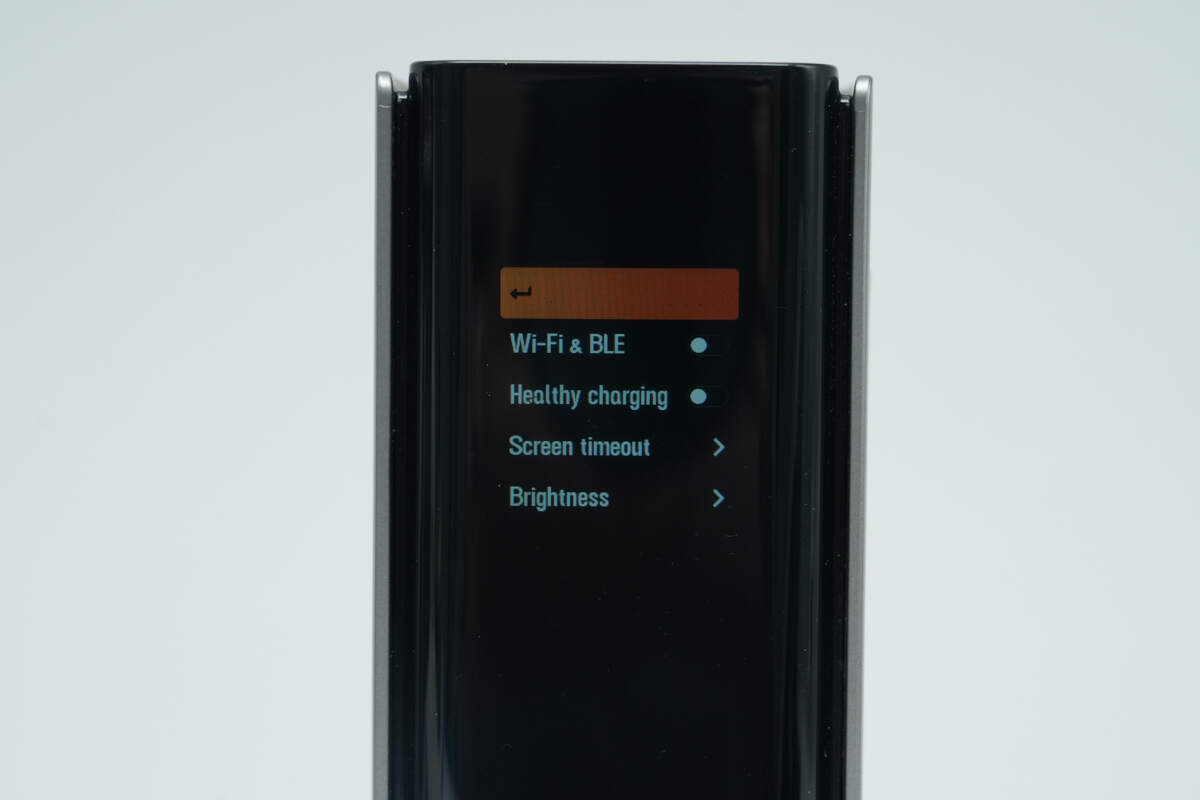
There are also features such as app connectivity and on-screen display settings, allowing customization based on user preferences.

It also provides real-time battery health and temperature monitoring on the display.
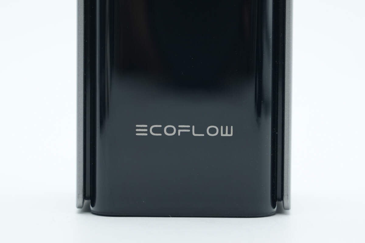
The bottom section features the EcoFlow logo.
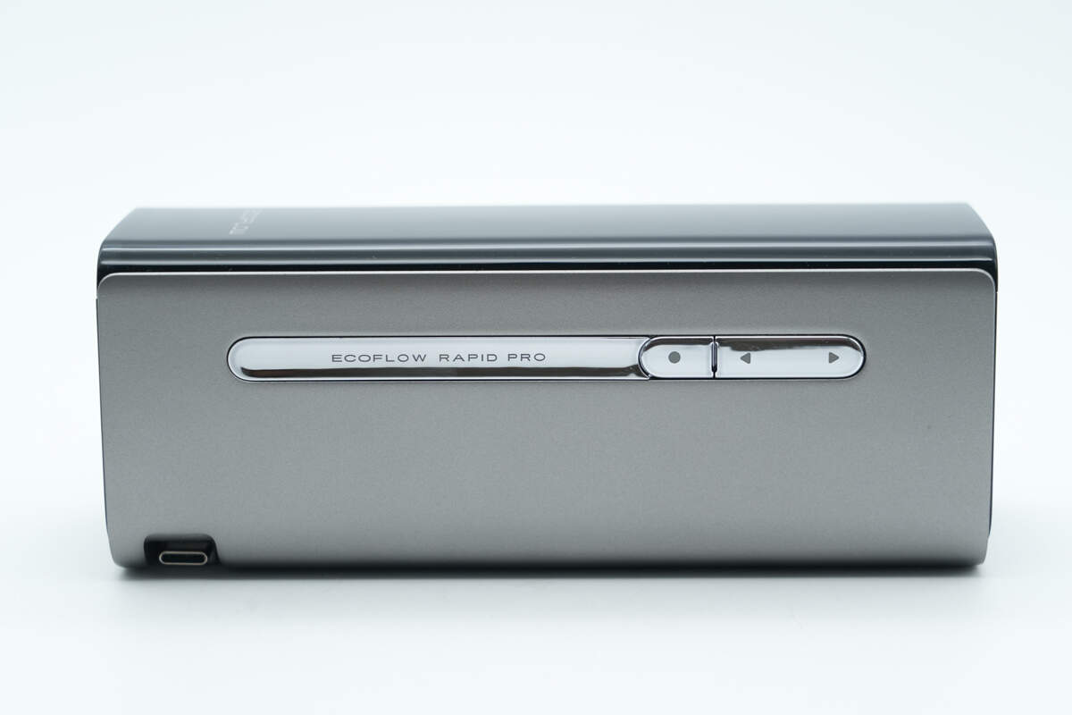
One side is equipped with a three-segment bright silver physical button.
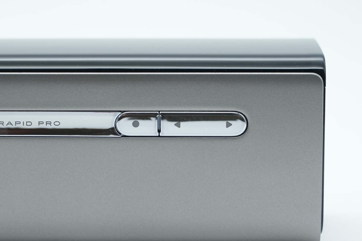
The three buttons function respectively as the power button, interface switch, and operation settings key.
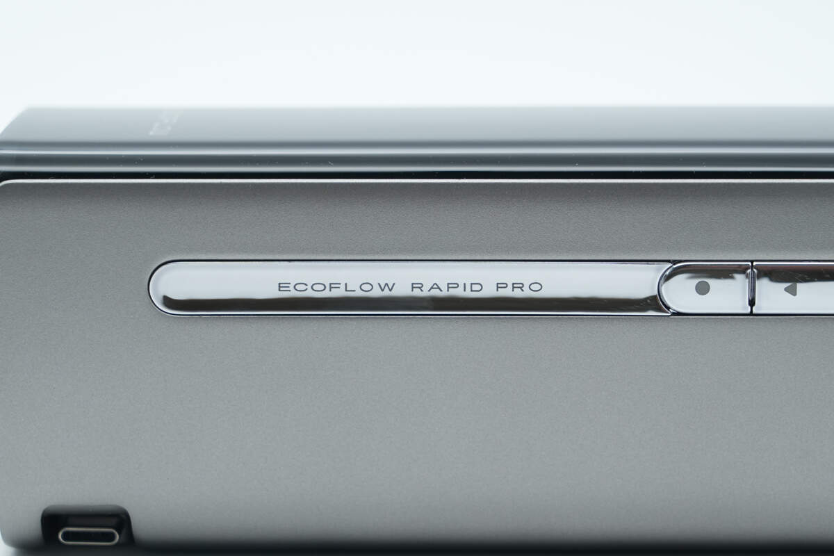
The left-side groove features the “ECOFLOW RAPID PRO” branding.
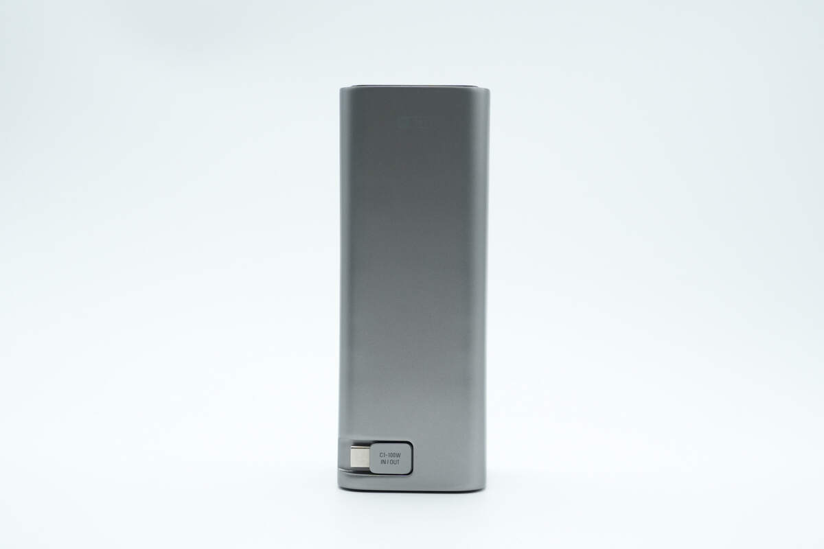
The retractable USB-C cable is located at the lower part of the back.
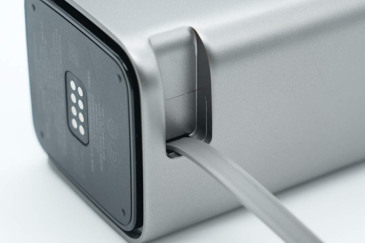
The storage slot features a magnetic design that securely holds the cable connector.
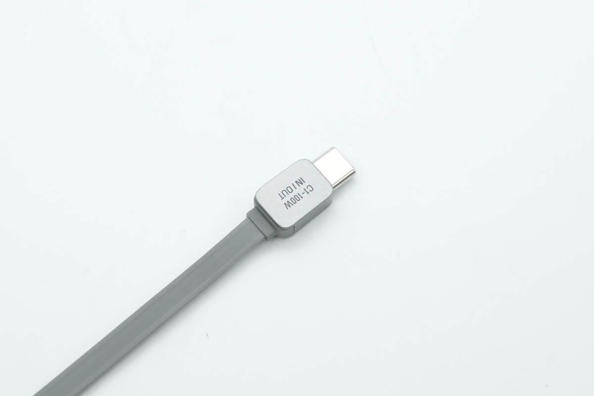
The USB-C1 built-in cable has a flat design.
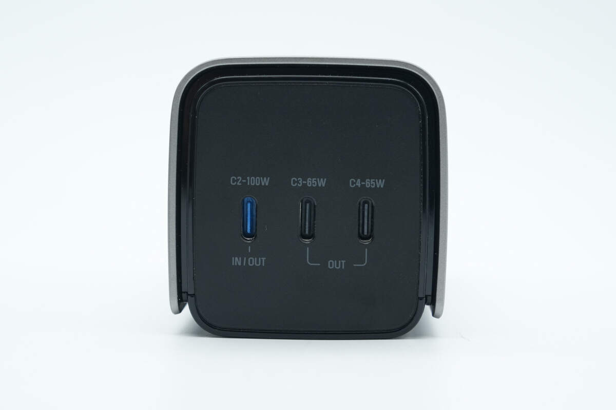
The top panel features a matte finish and includes three USB-C ports.
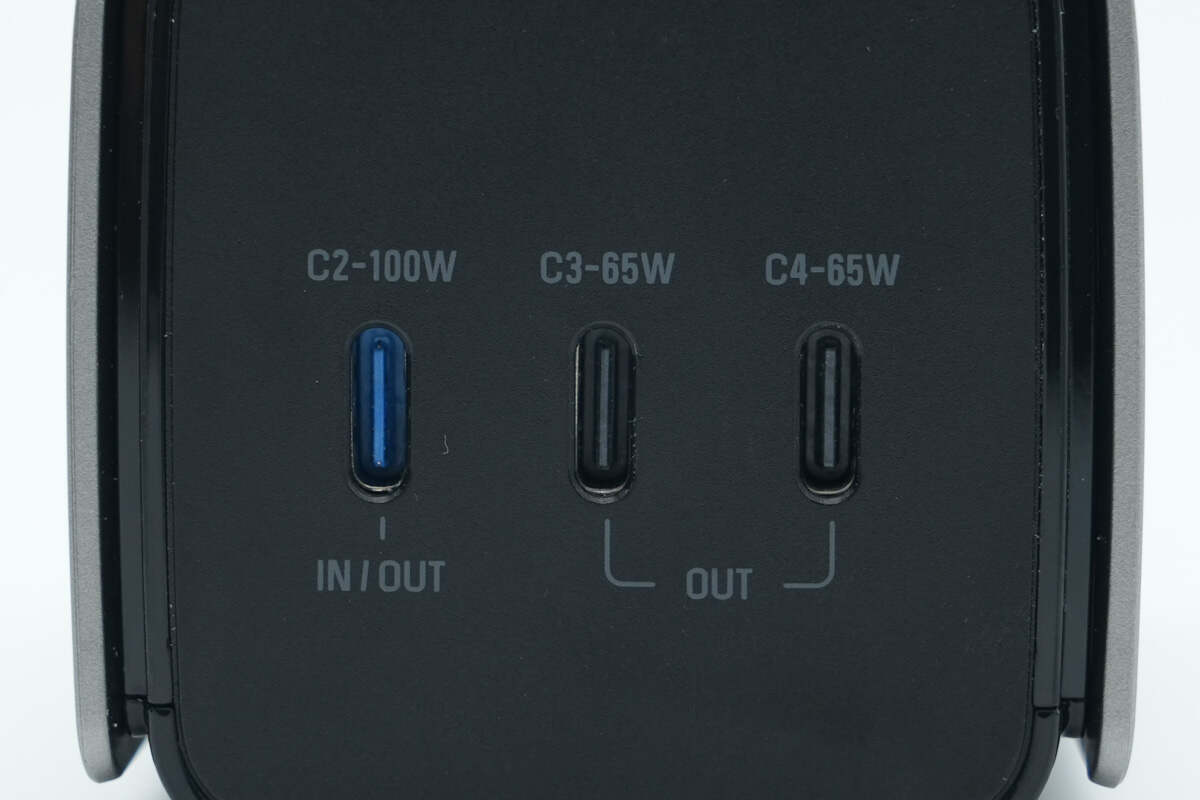
On both sides of the ports are printed labels for IN, OUT, port numbers, and specifications. The USB-C2 port, which supports bidirectional fast charging, is distinguished by a blue plastic sheet.
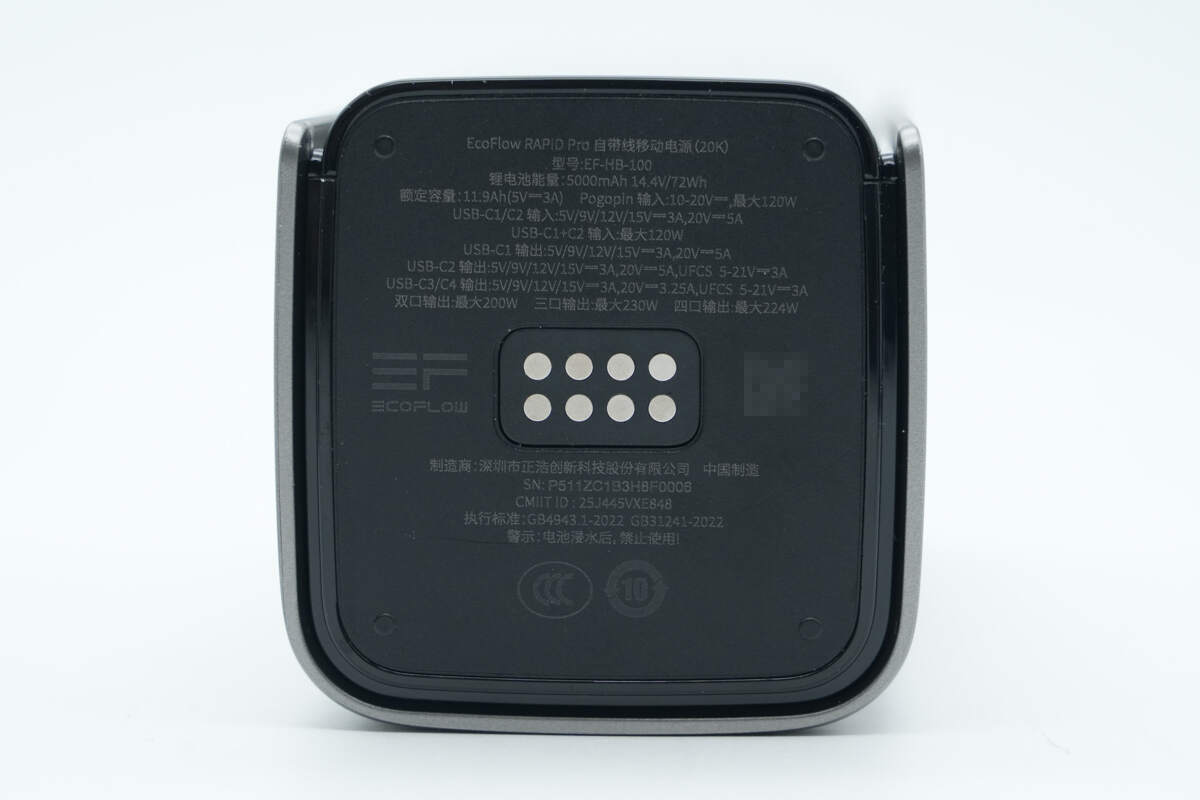
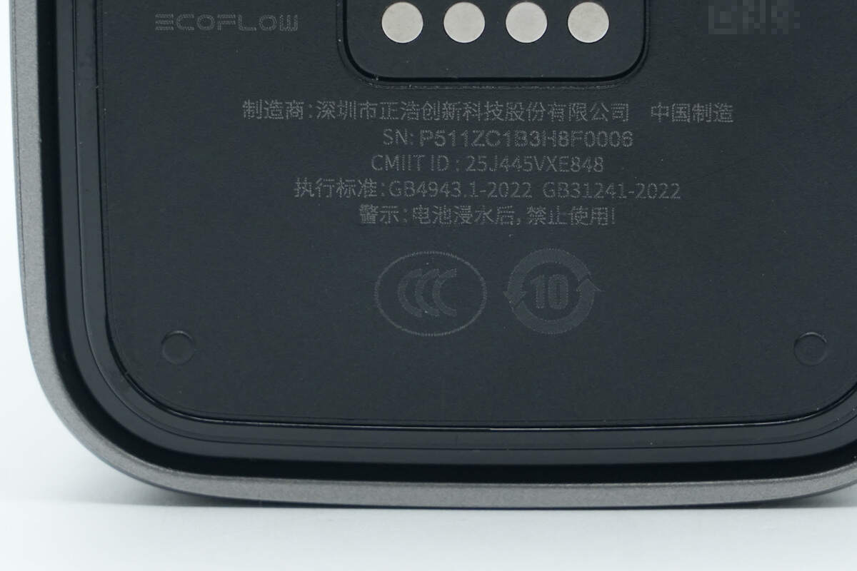
The bottom displays the specification information, with contact points at the center for connecting to the EcoFlow RAPID Pro 320W charging station.

Model: EF-HB-100
Lithium Battery Capacity: 5000mAh 14.4V / 72Wh
Rated Capacity: 11.9Ah (5V 3A)
Input:
Pogo Pin: 10-20V, 120W Max
USB-C1/C2: 5/9/12/15V 3A, 20V 5A
USB-C1 + C2: 120W Max
Output:
USB-C1: 5/9/12/15V 3A, 20V 5A
USB-C2: 5/9/12/15V 3A, 20V 5A, UFCS 5-21V 3A
USB-C3/C4: 5/9/12/15V 3A, 20V 3.25A, UFCS 5-21V 3A
Dual-port output: 200W Max
Triple-port output: 230W Max
Four-port output: 224W Max
It has obtained CCC certification.
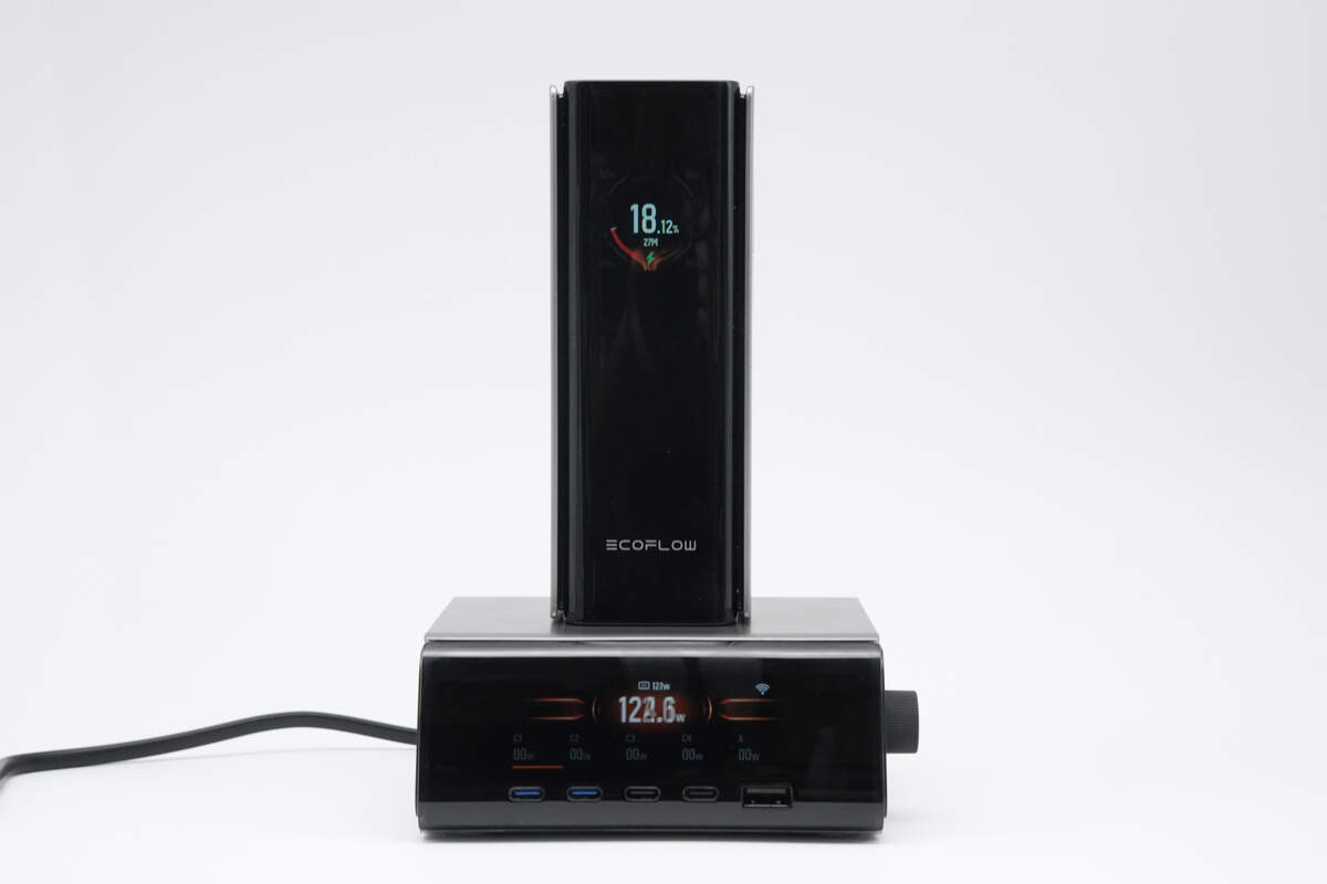
Simply place it on the EcoFlow RAPID Pro 320W charging station to activate 120W charging—offering convenient plug-and-charge functionality.
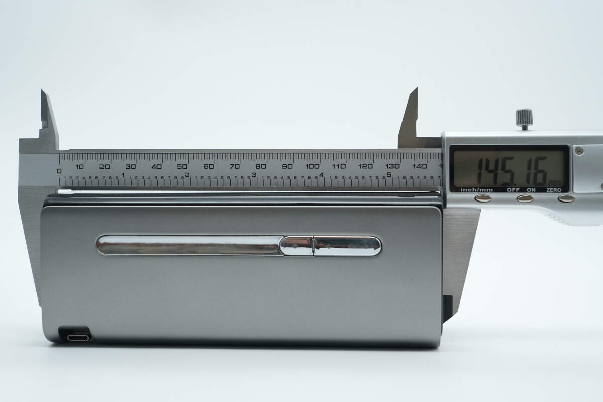
The length of the power bank is about 145.16 mm (5.71 inches).
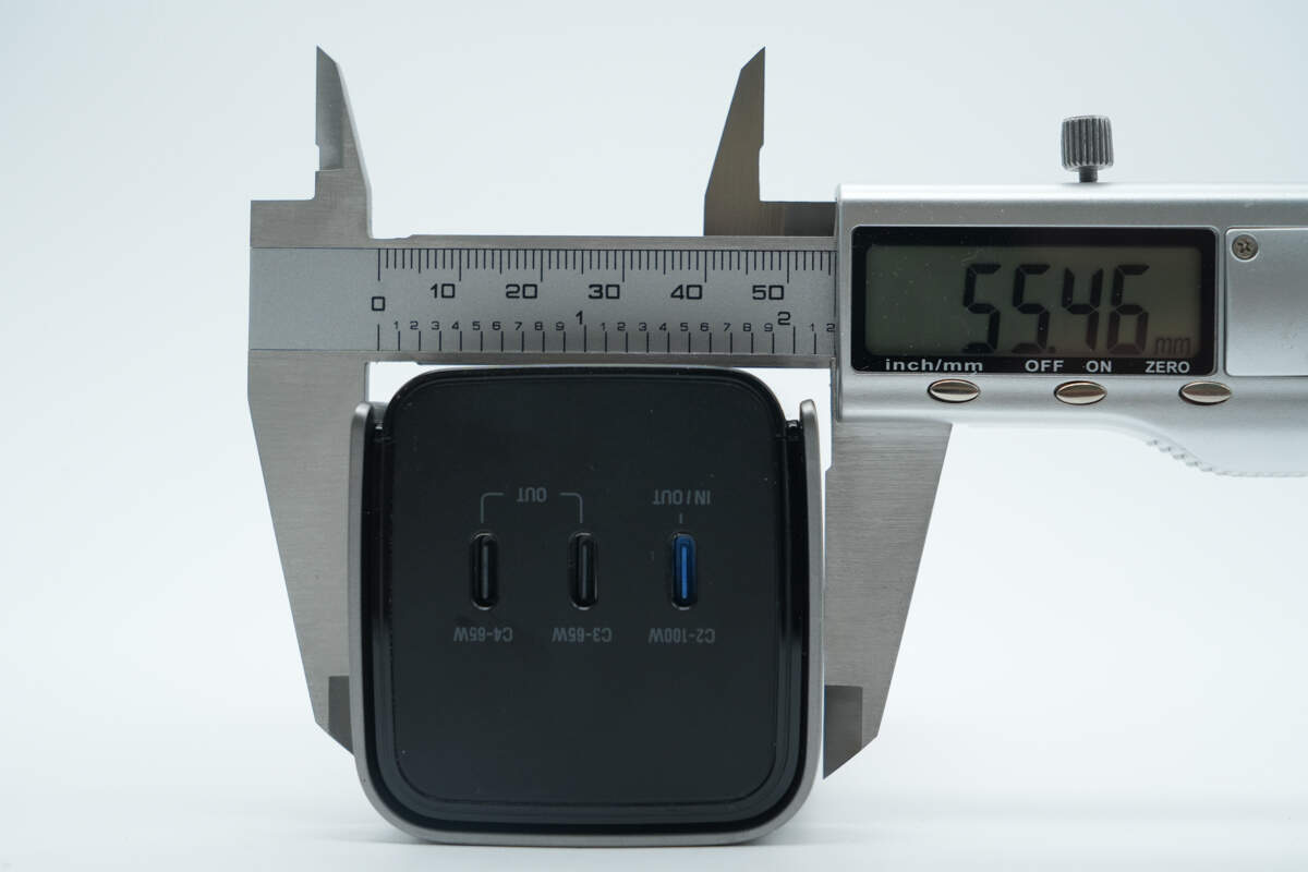
The width is about 55.46 mm (2.18 inches).
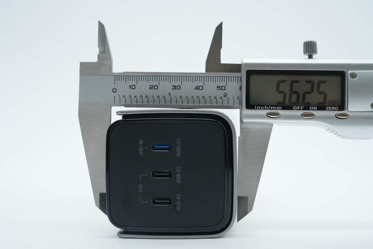
The thickness is about 56.25 mm (2.21 inches).
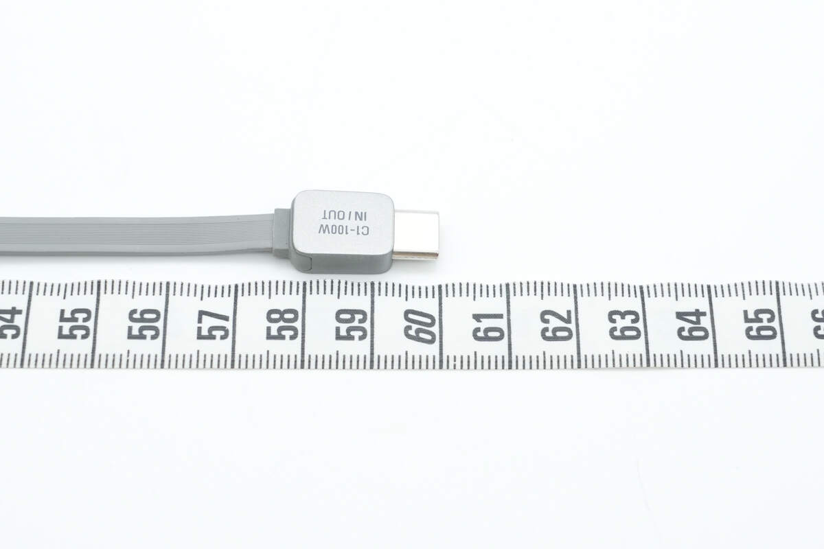
The length of the retractable cable is about 60 cm (23.62 inches).
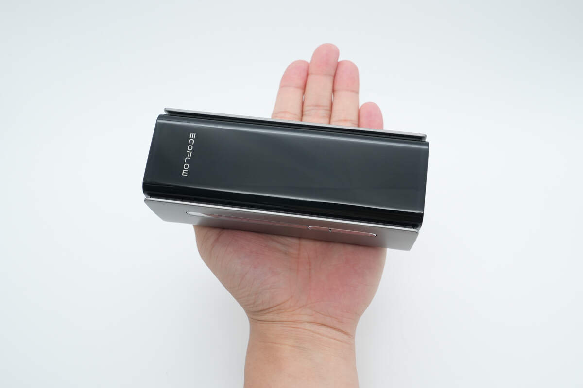
That's how big it is in the hand.
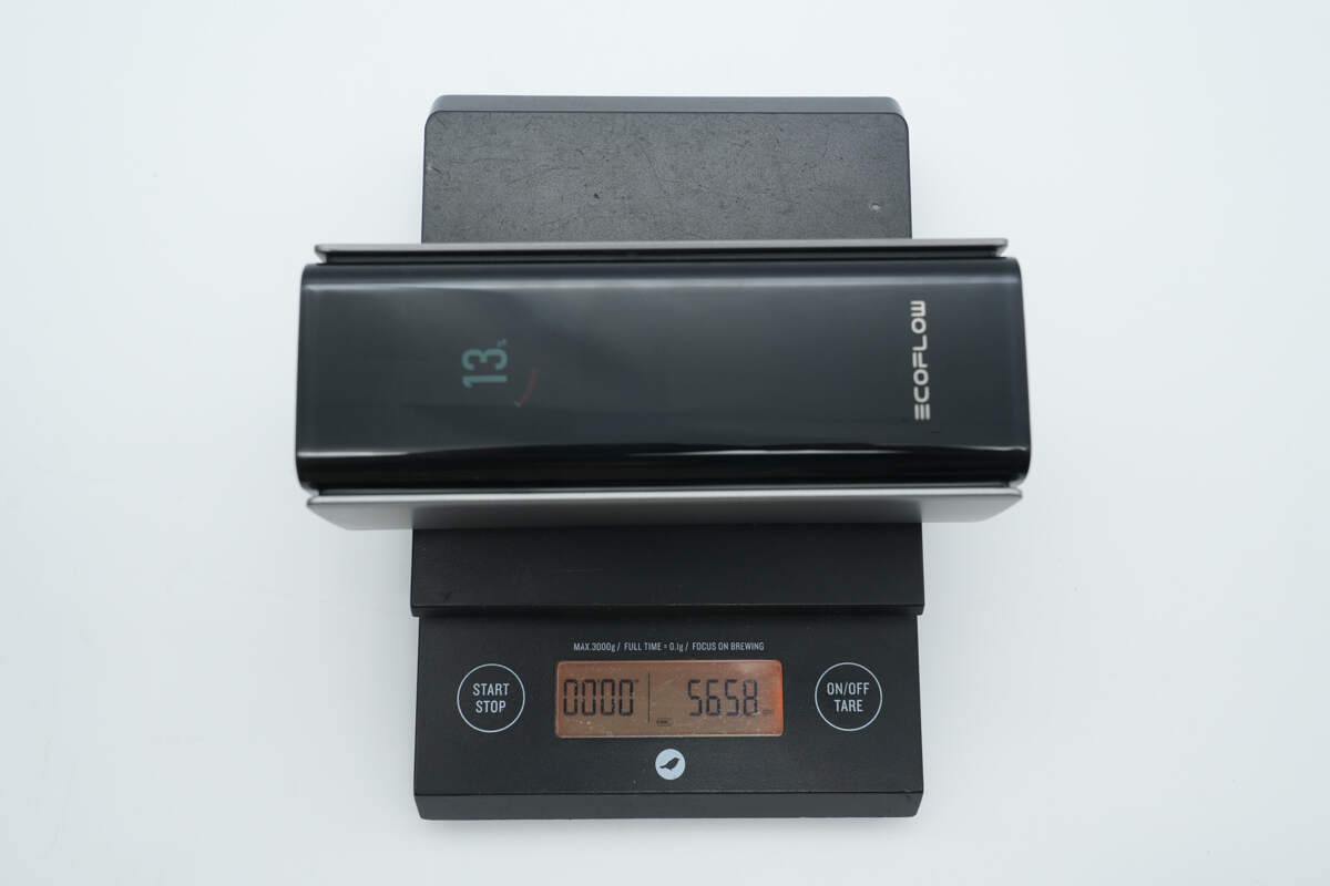
The weight is about 566 g (19.97 oz).
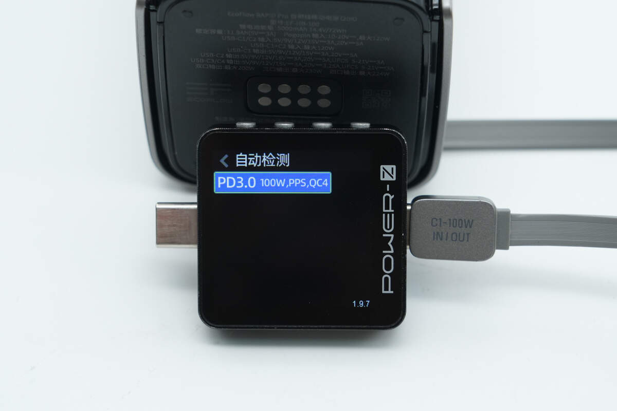
ChargerLAB POWER-Z KM003C shows that the retractable USB-C1 cable supports PD3.0, PPS, and QC4 charging protocols.
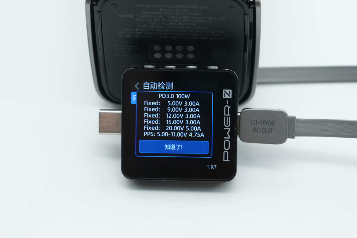
And it has five fixed PDOs of 5V3A, 9V3A, 12V3A, 15V3A, and 20V5A. It has one set of PPS, which is 5-11V4.75A.
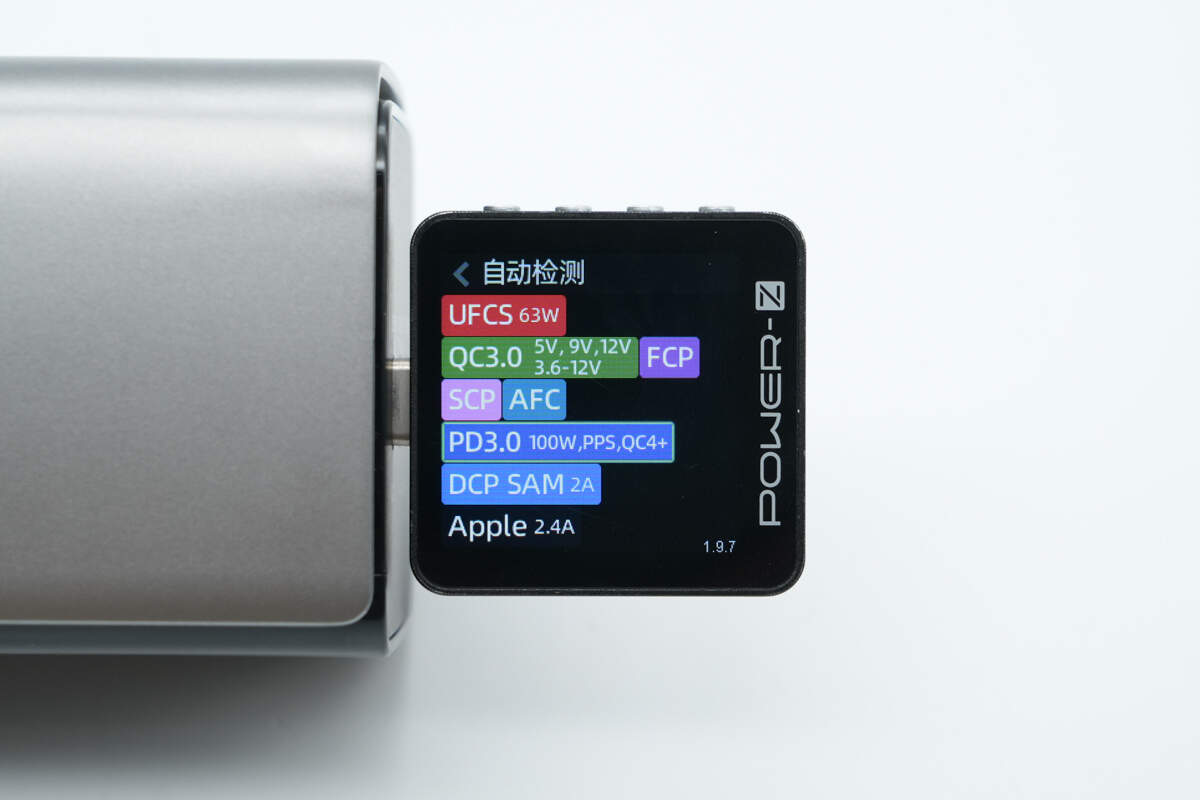
Testing shows that the USB-C2 supports UFCS, QC3.0/4+, FCP, SCP, AFC, PD3.0, PPS, DCP, SAM 2A, and Apple 2.4A charging protocols.
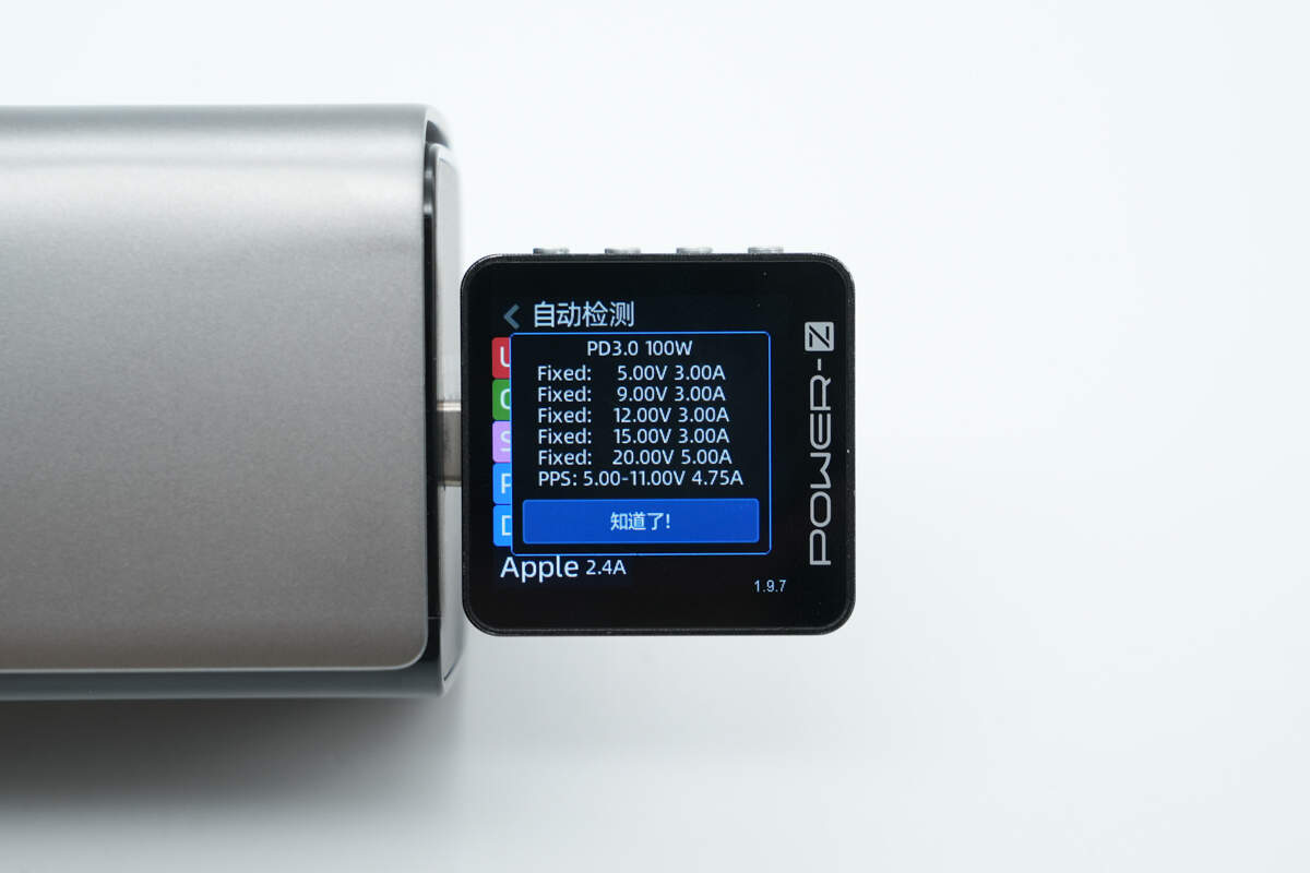
And it has five fixed PDOs of 5V3A, 9V3A, 12V3A, 15V3A, and 20V5A. It has one set of PPS, which is 5-11V4.75A.
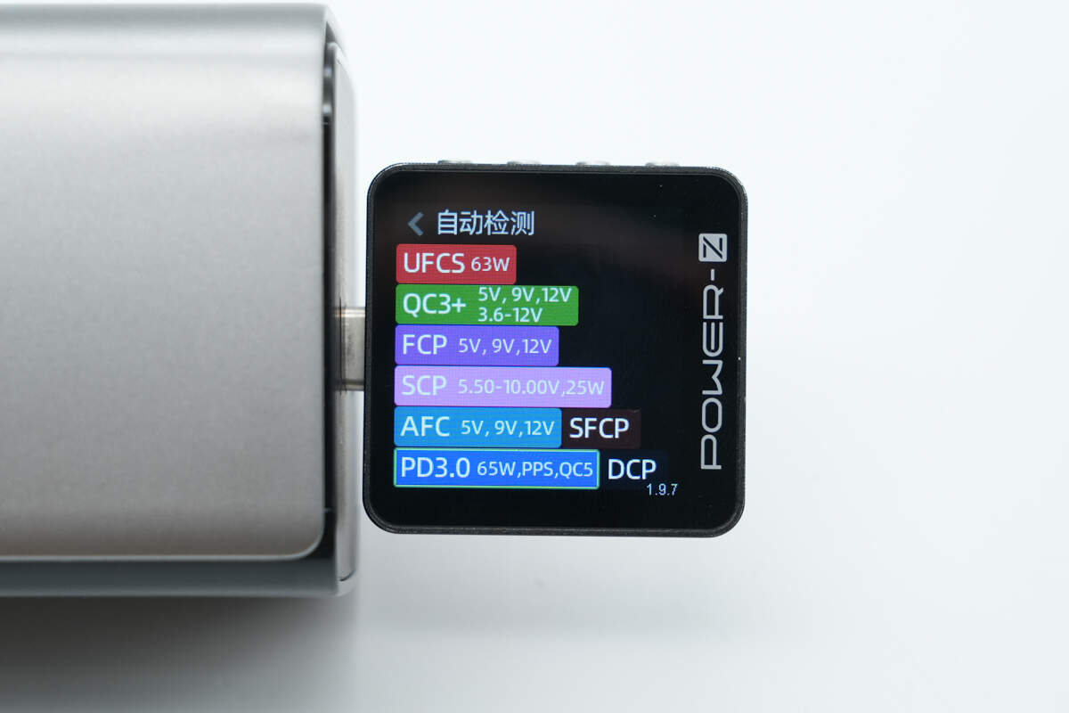
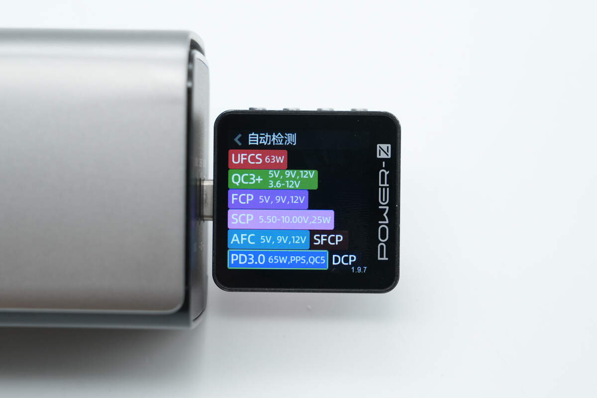
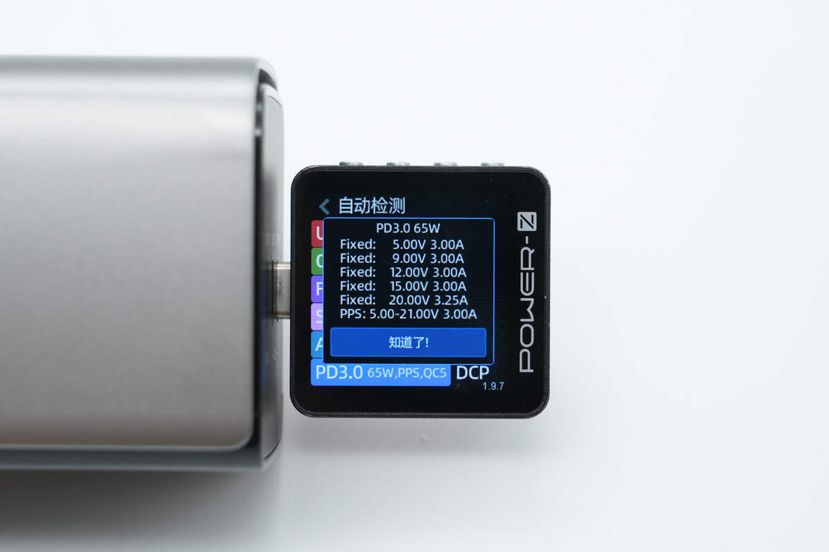
The USB-3 supports UFCS, QC3+/5, FCP, SCP, AFC, SFCP, PD3.0, PPS, and DCP charging protocols.
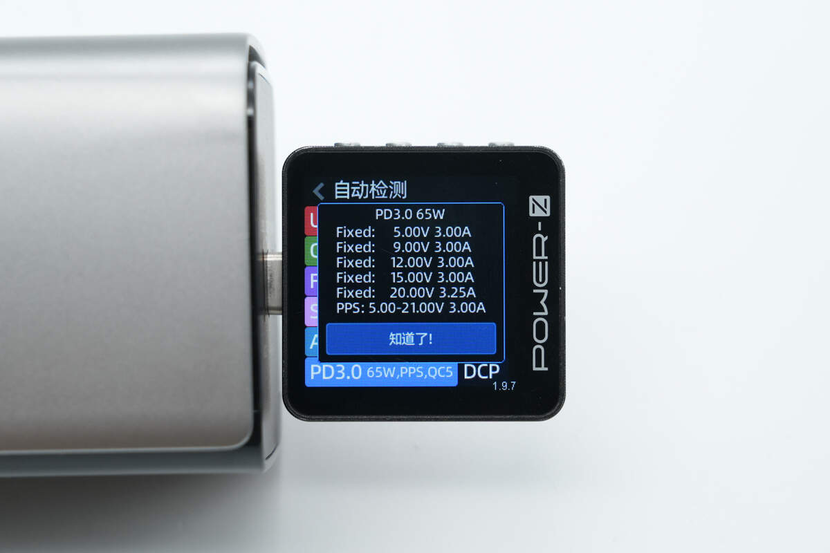
And it has five fixed PDOs of 5V3A, 9V3A, 12V3A, 15V3A, and 20V3.25A. It has one set of PPS, which is 5-21V3A.
Testing shows that USB-C4 supports the same protocols as USB-C3.
The PDO messages are exactly the same as well.
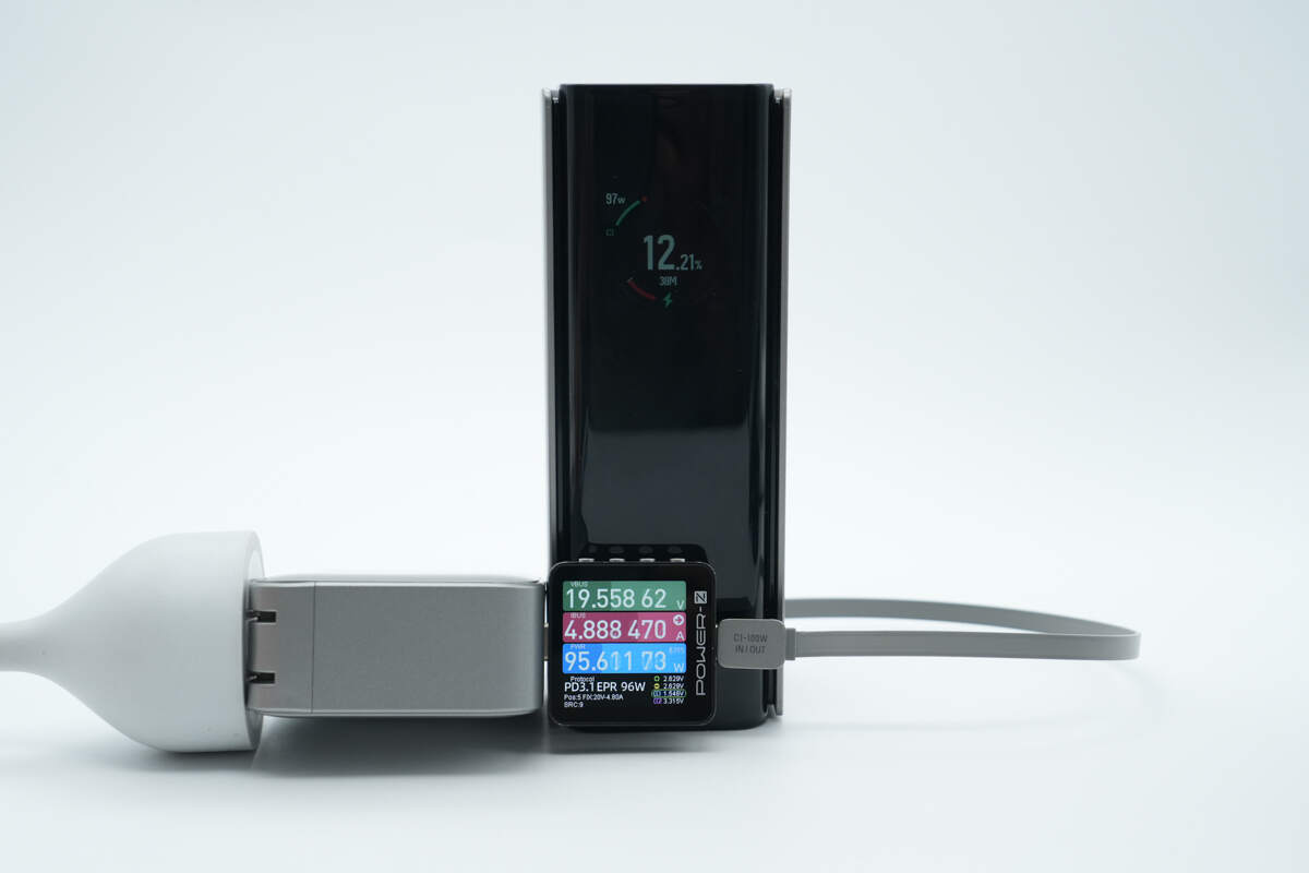
Using the EcoFlow RAPID Pro 140W GaN charger to charge the power bank via the built-in USB-C1 cable, the charging power reaches about 95.61W, successfully activating 20V 5A (100W) PD fast charging.
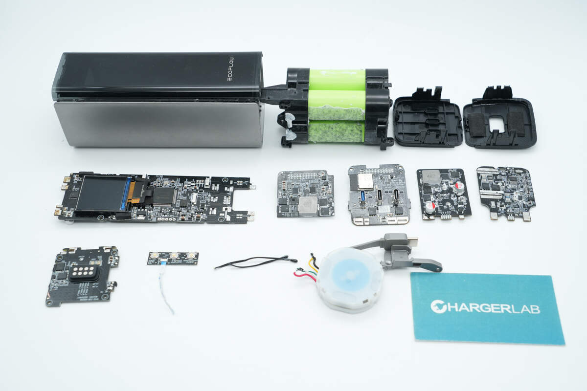
Teardown
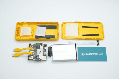
Next, let's take it apart to see its internal components and structure.
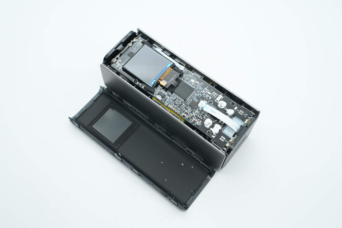
The front panel is secured with clips.
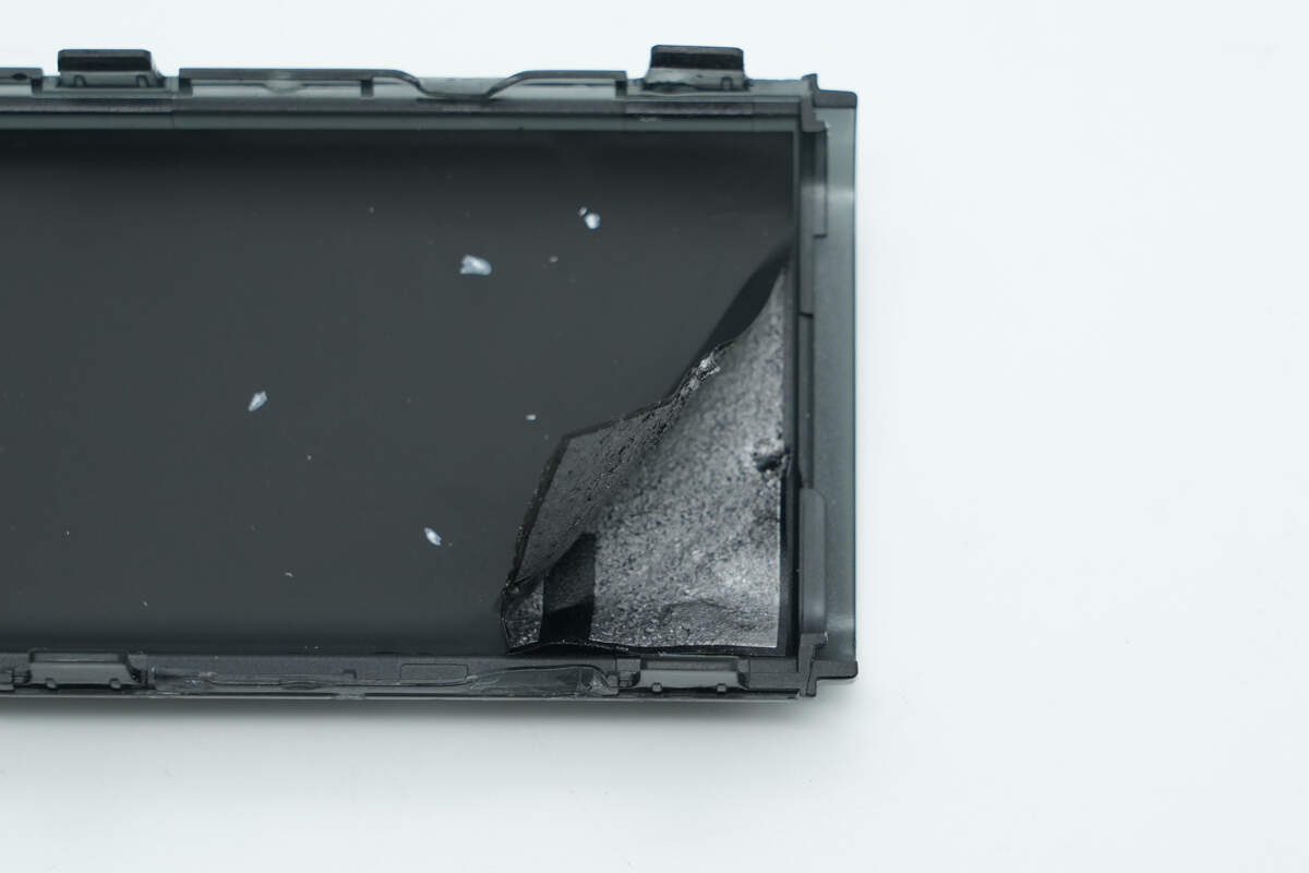
The inner side of the panel is lined with a graphite sticker and insulated for protection.
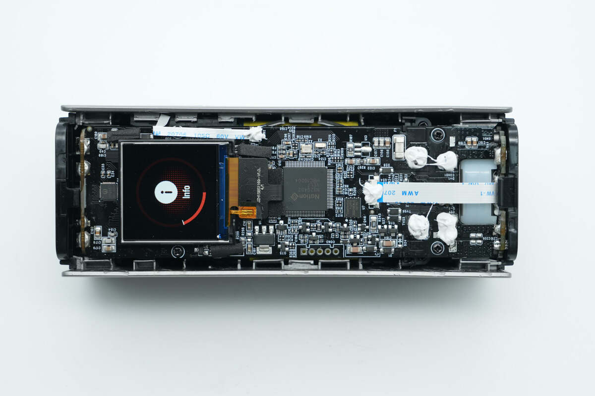
The top and both ends are equipped with PCBs, which are secured together by soldering. The top PCB is further reinforced with screws.

The top PCB has a cutout corresponding to the retractable cable module.
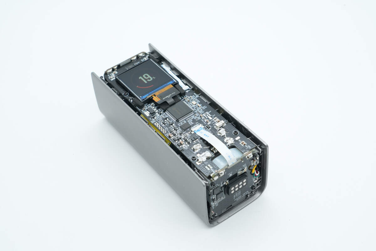
Remove the panels on both ends.
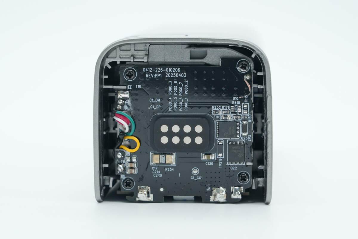
The PCB with the PogoPin input contacts is secured with screws. The core wires of the built-in USB-C cable are soldered to this PCB.
The PCB housing the three USB-C sockets on the other end is also secured with screws.
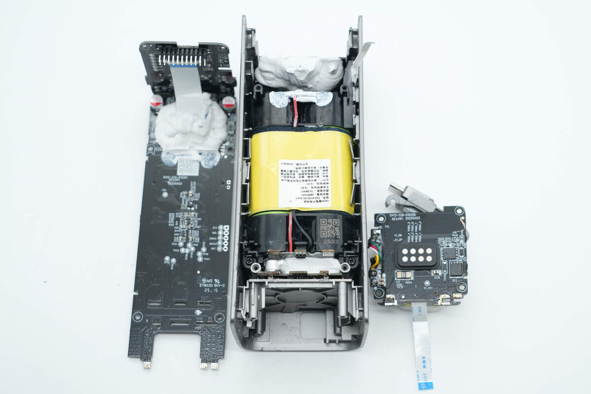
Remove the screws on both ends to take out the PCBA module, revealing the battery pack underneath.

At the contact end, there is a plastic isolation plate that also serves to reinforce the retractable cable module.
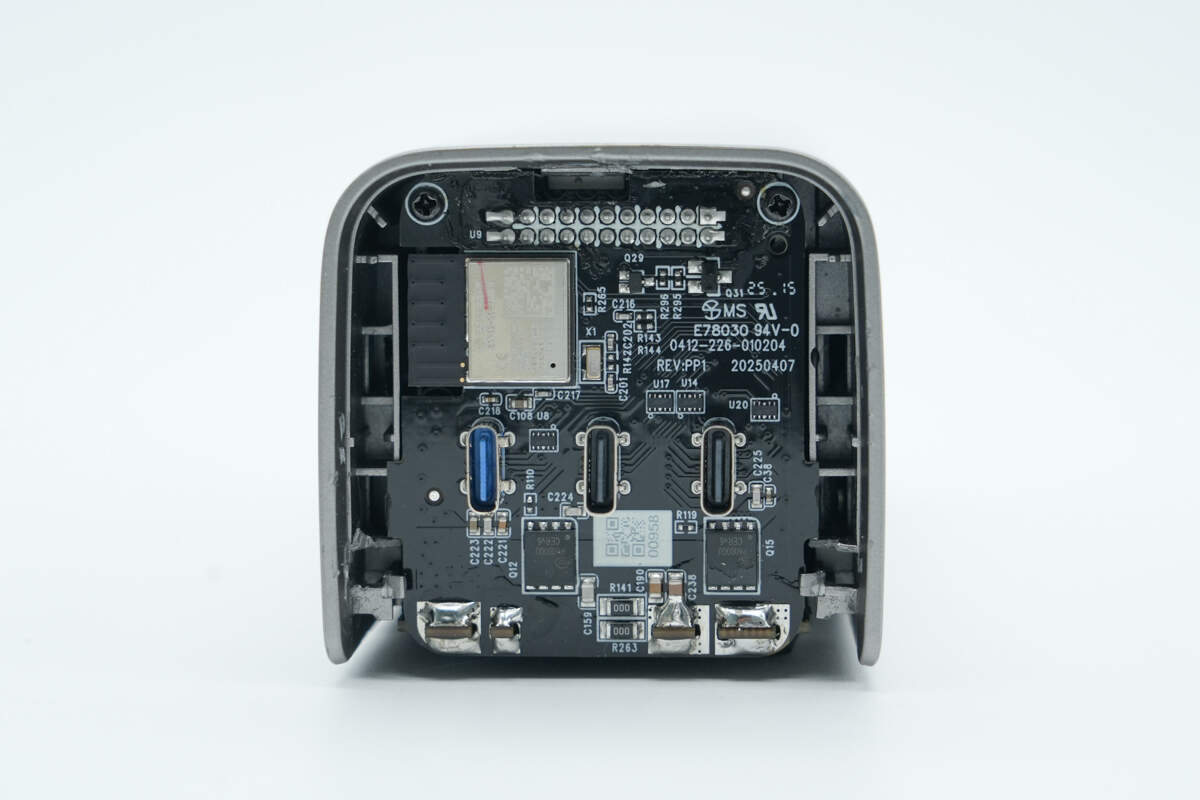
At the port end, there is a second PCB connected to the PCB with the USB-C sockets via pin headers.
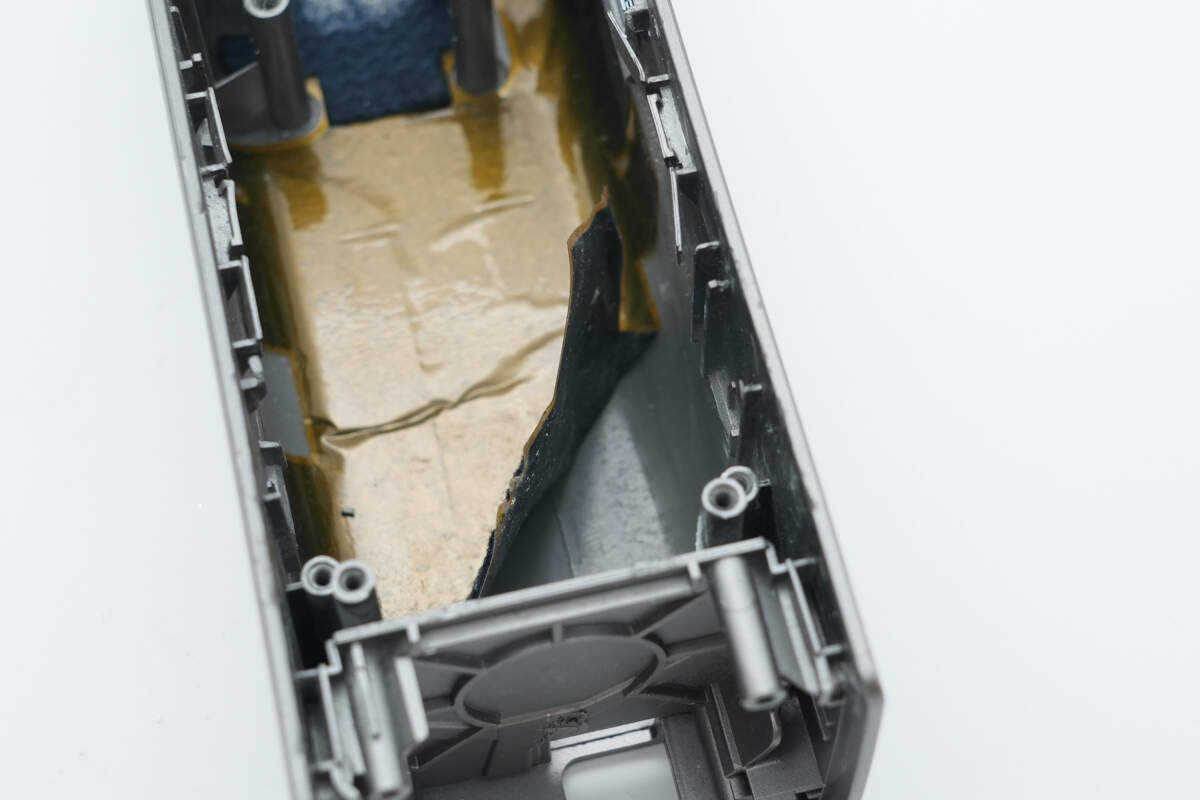
Remove the battery pack; the compartment is lined with a graphite thermal pad and also features insulation treatment.
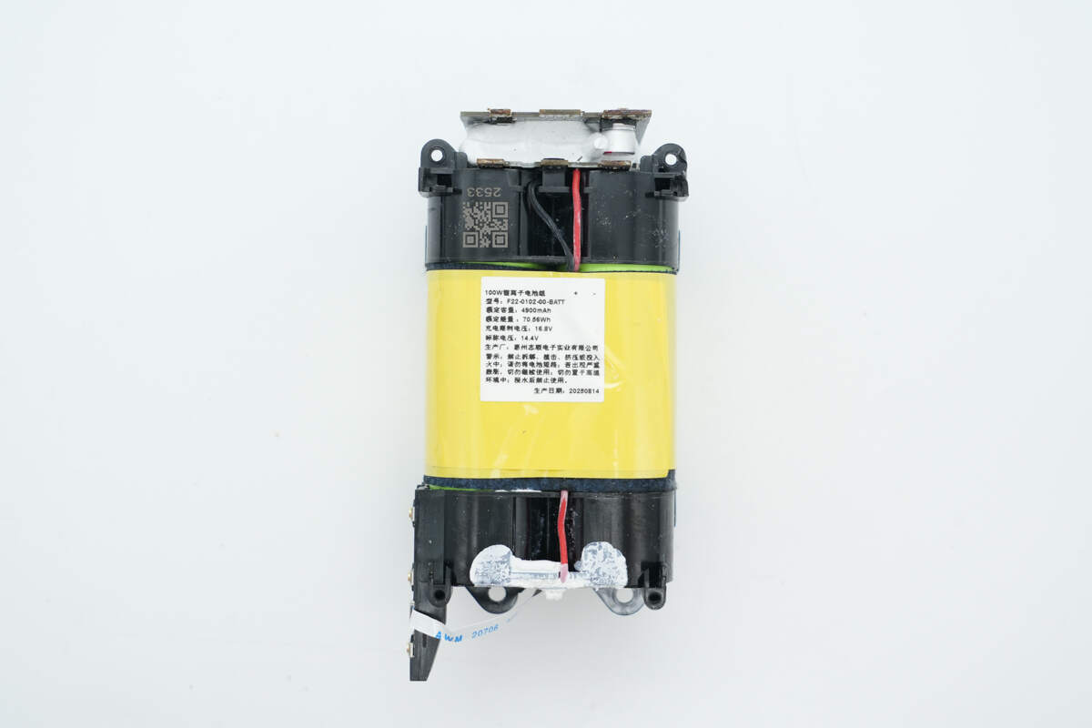
The battery pack is encased in plastic shells at both ends, with insulation tape wrapped around the middle and a nameplate attached.
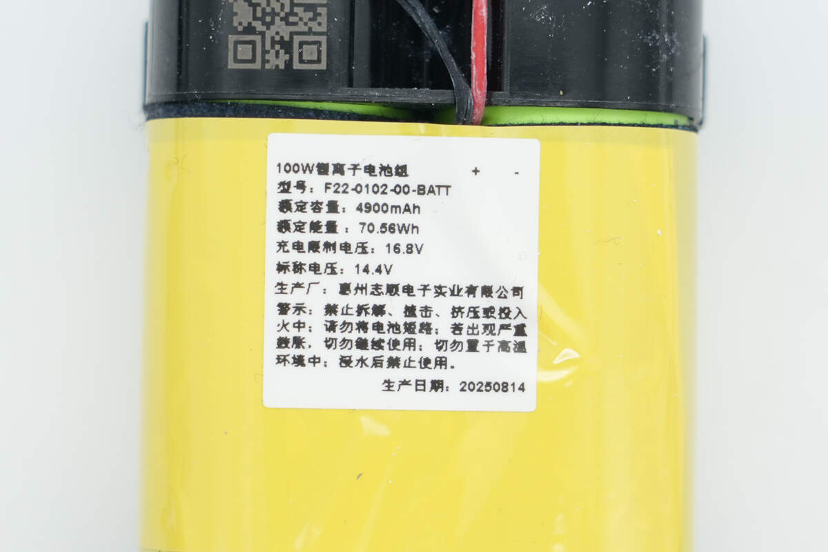
Model: F22-0102-00-BATT
Rated Capacity: 4900mAh
Rated Energy: 70.56Wh
Charge Cut-off Voltage: 16.8V
Nominal Voltage: 14.4V
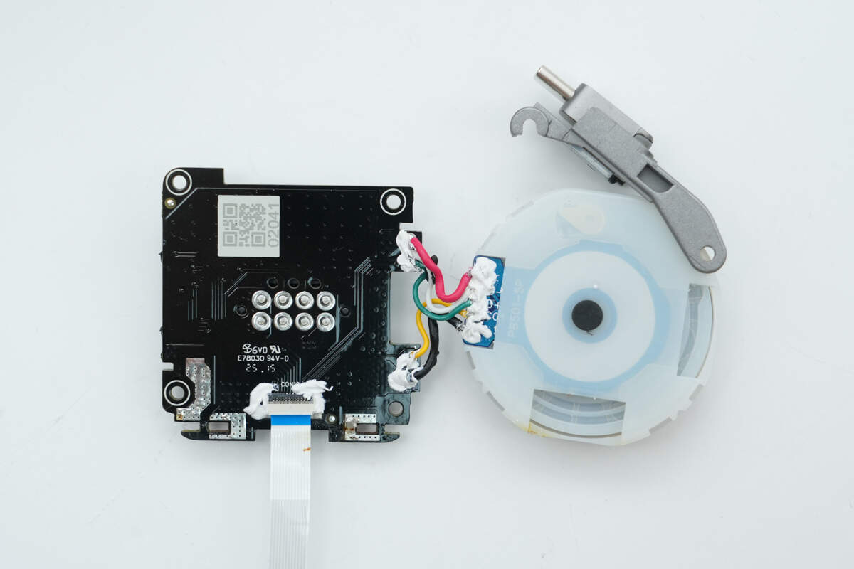
One end of the plastic shell features a button PCB, which is connected via a flexible ribbon cable with a plug-and-play interface.
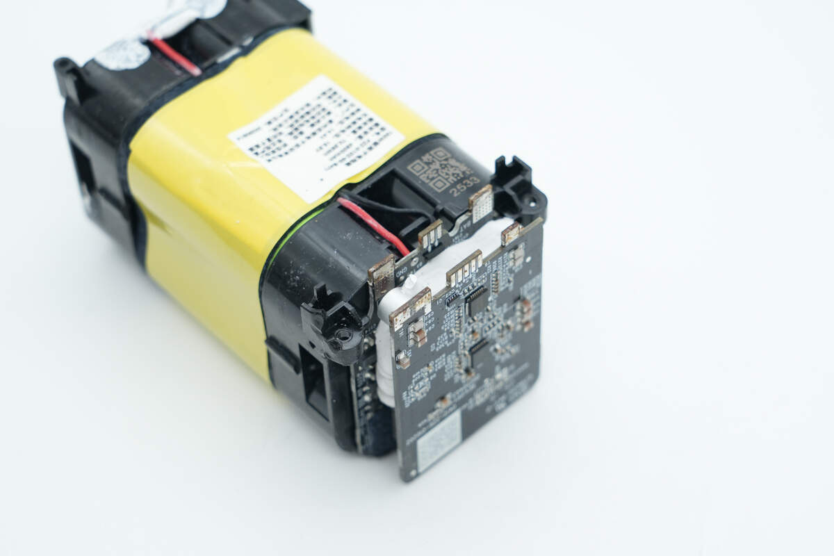
The other end connects to two PCBs, with white adhesive filling the gap between them.
Remove the front PCB. The inner PCB is soldered to the battery pack.

Remove the inner PCB as well.
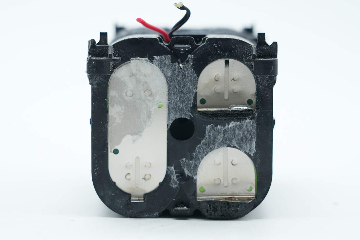
The cells are connected by nickel strips, which are spot-welded between them.

Peel off the insulation tape. The battery cells have thermistors attached for temperature monitoring.
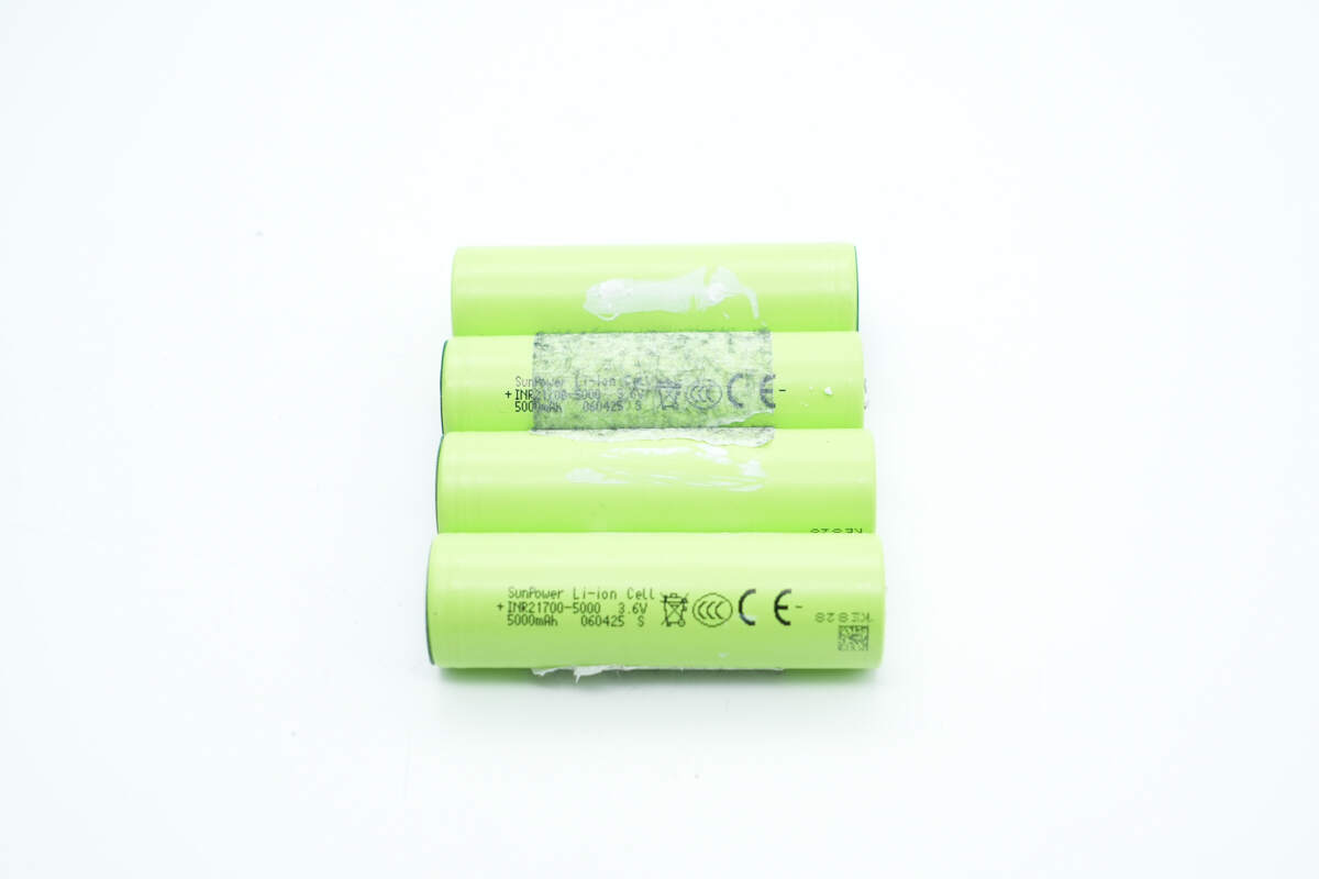
Disassemble the battery pack. It consists of four 21700 lithium-ion cells with the same part number.
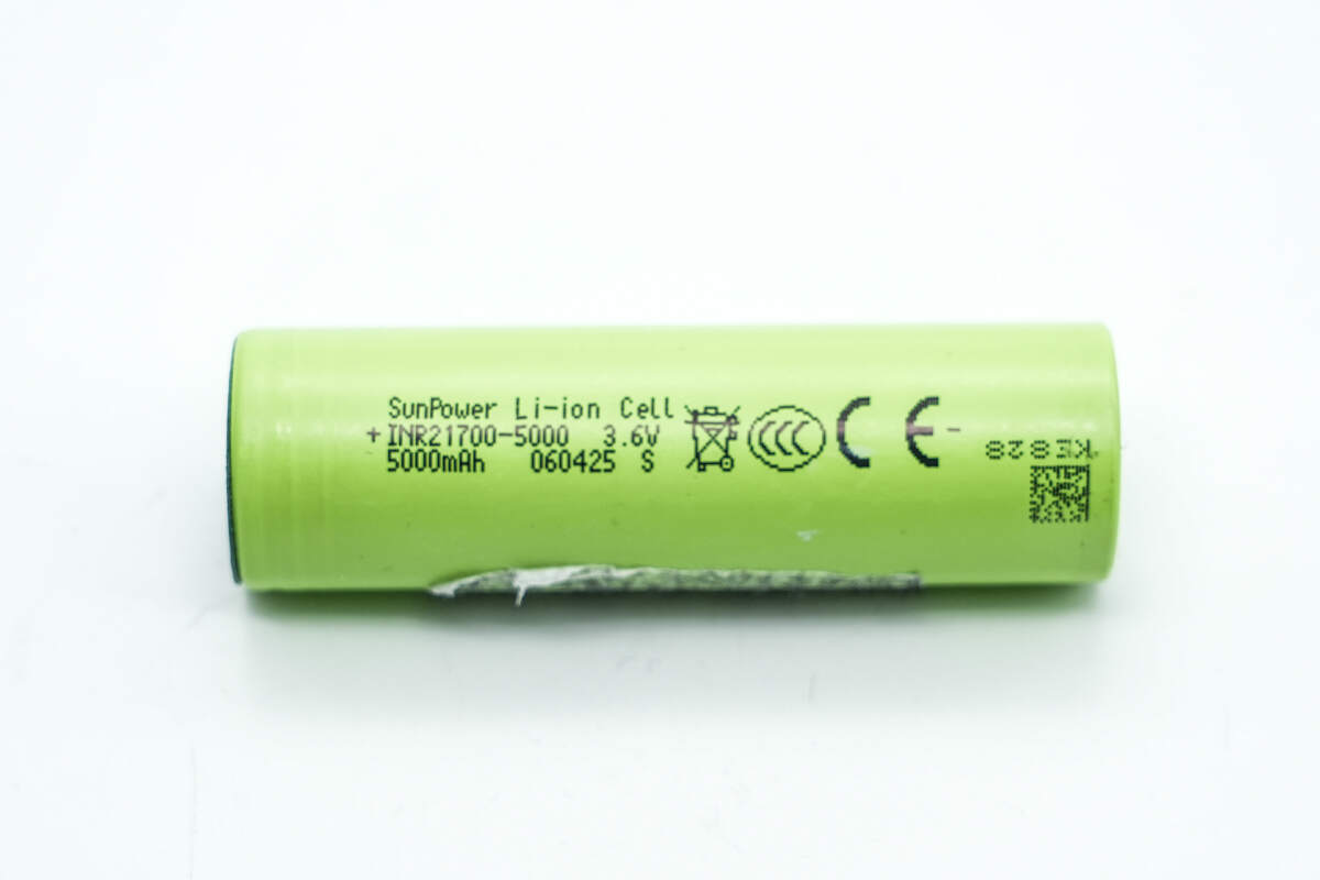
The cells are from SunPower, model INR21700-5000. They have a nominal voltage of 3.6V, a nominal capacity of 5000mAh, and a charge cut-off voltage of 4.2V. The cells are CCC and CE certified.
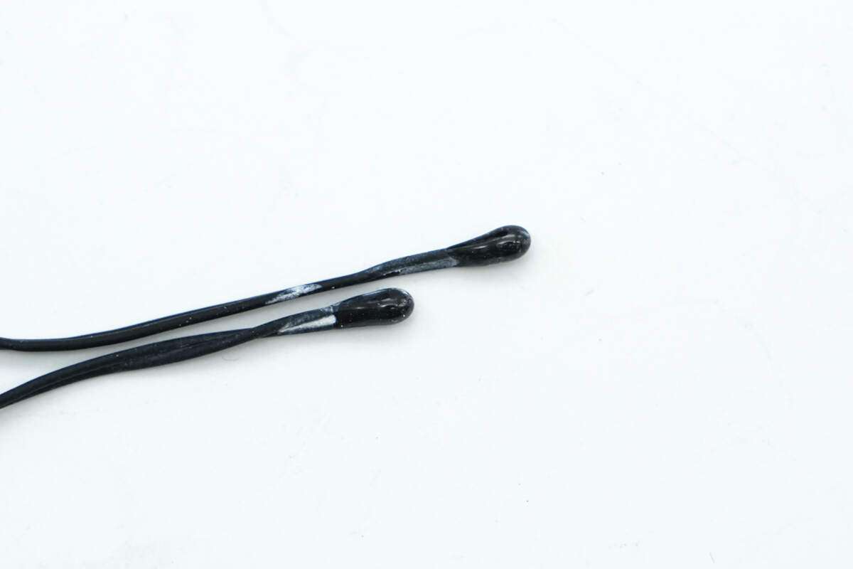
Close-up of the two thermistors.
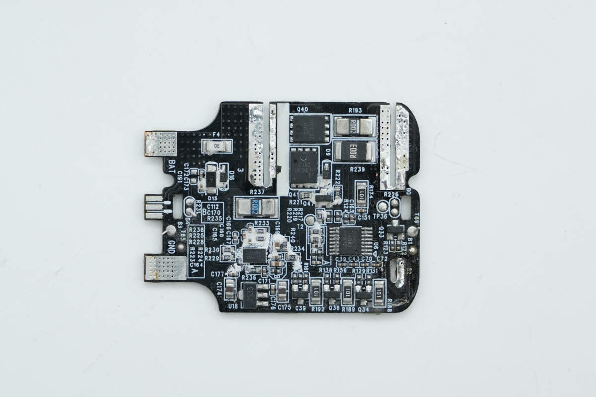
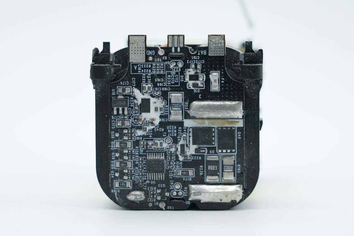
The lithium battery protection PCB connected to the battery pack features an SMD fuse, battery protection chip, battery protection MOSFETs, battery fuel gauge, and balancing circuit on the front.
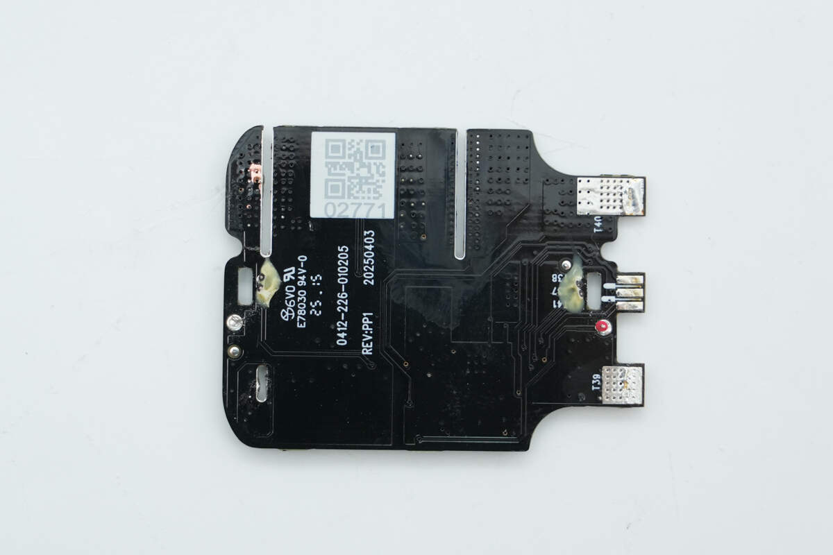
The other side of the PCB is free of components.
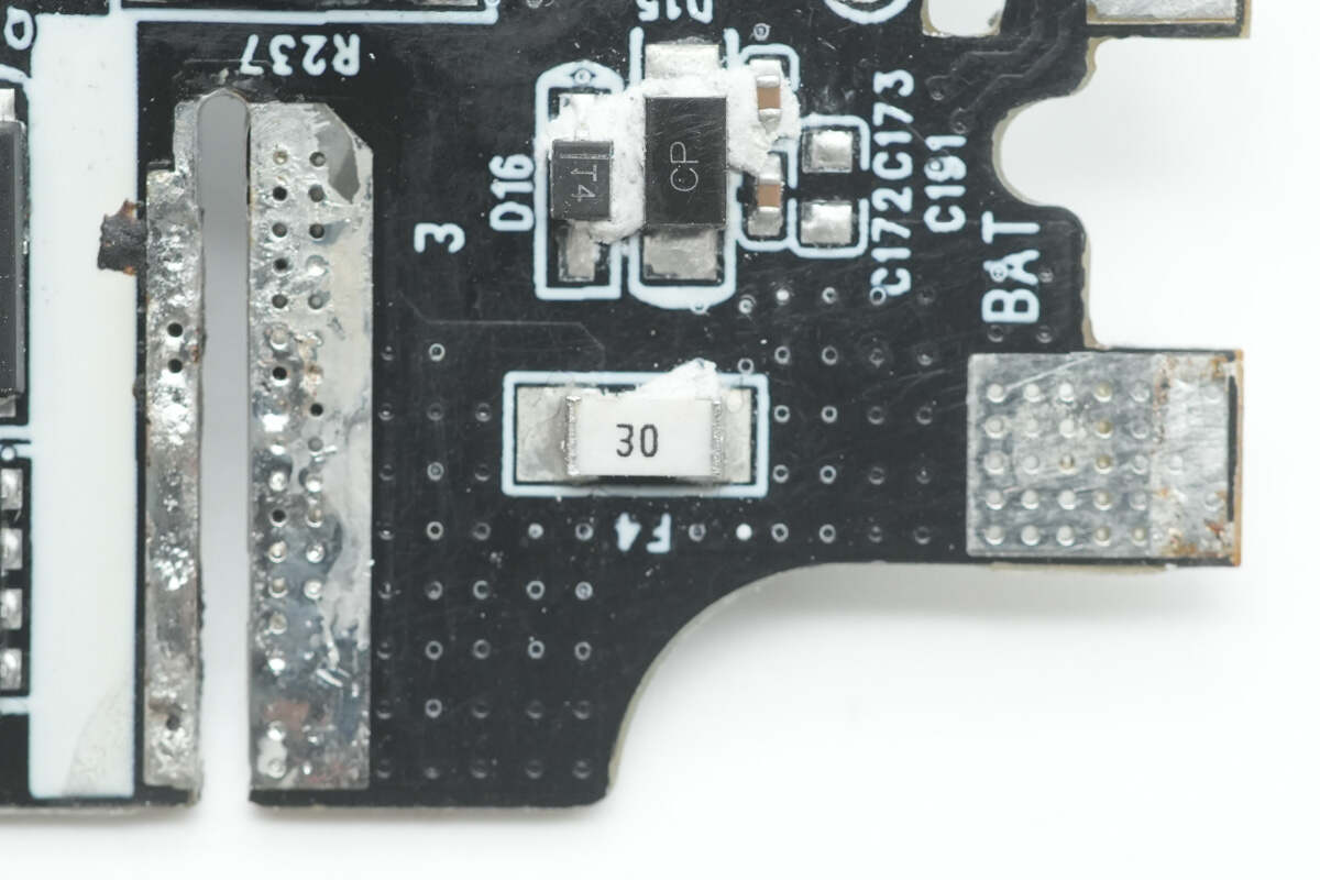
Close-up of the SMD fuse.

The battery protection chip is from Cellwise, model CW1244. It is a 3-4 series lithium battery protection IC that supports various types of lithium batteries, including lithium iron phosphate (LiFePO4) and high-voltage platforms. It offers features such as battery balancing, high-precision overcharge, over-discharge, and overcurrent protection. It also supports battery temperature protection and open-circuit protection, among other functions.
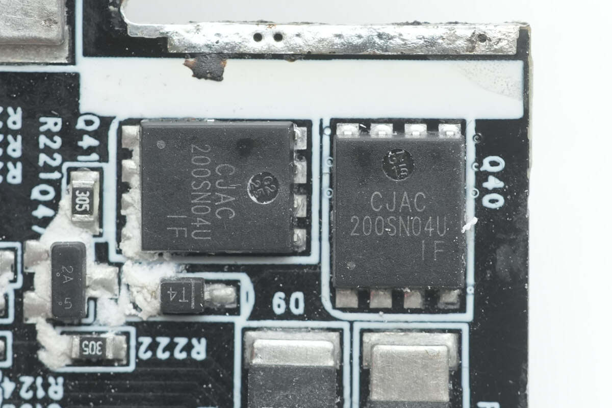
The battery protection MOSFETs are from JSCJ, model CJCA200SN04U. They are NMOS type with a voltage rating of 40V, a conduction resistance of 0.67mΩ, and are packaged in a PDFNWB 5*6-8L form factor.
Close-up of the balancing circuit.
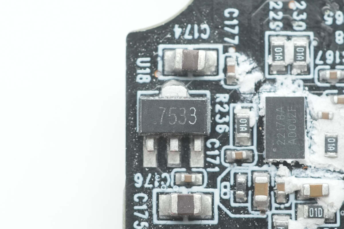
Close-up of the voltage regulator chip marked with "7533."
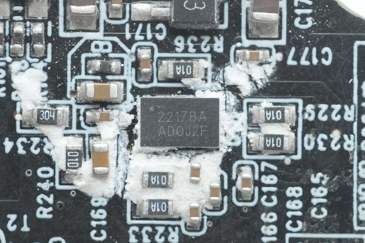
The battery fuel gauge is from Cellwise, model CW2217BAAD. It features a built-in 14-bit ADC for temperature and voltage monitoring, and a 16-bit ADC for current measurement. The chip supports a 1mΩ sense resistor and is compatible with lithium-manganese, lithium-cobalt, and lithium-polymer battery applications. It is packaged in a DFN-12 form factor.

The USB-C port PCB is soldered to the top PCB. The backside of both PCBs also has a ribbon cable connection, and the sockets are extensively filled with white adhesive for reinforcement.
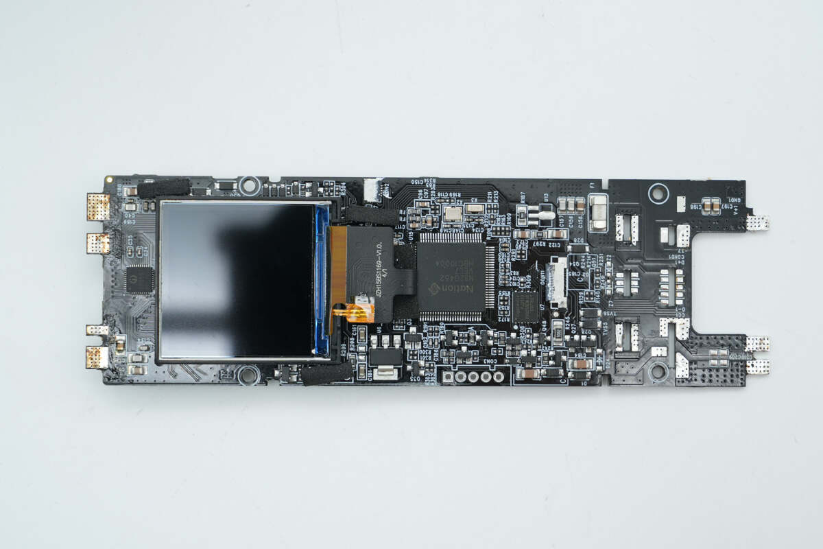
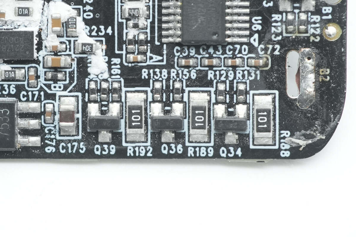
Separate the two PCBs. The top PCB features an MCU, memory, LDO voltage regulator, and a buck-boost SOC for the USB-C3 and USB-C4 ports. The display is connected to the PCB via a ribbon cable.
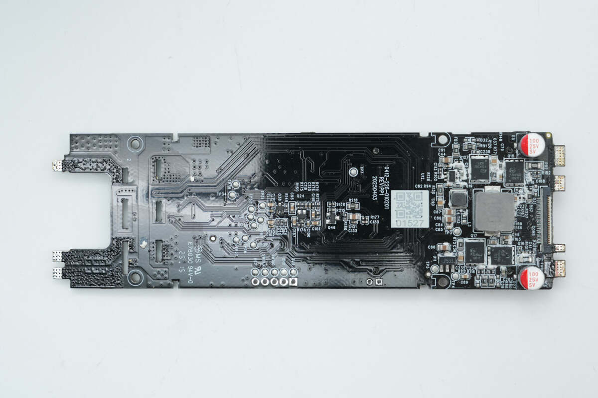
Remove the white adhesive from the back. The backside features buck-boost MOSFETs for the USB-C3 and USB-C4 interfaces, along with buck-boost inductors and output solid capacitors. Additionally, there is a synchronous buck converter and a buck inductor that supply power to the MCU and display.
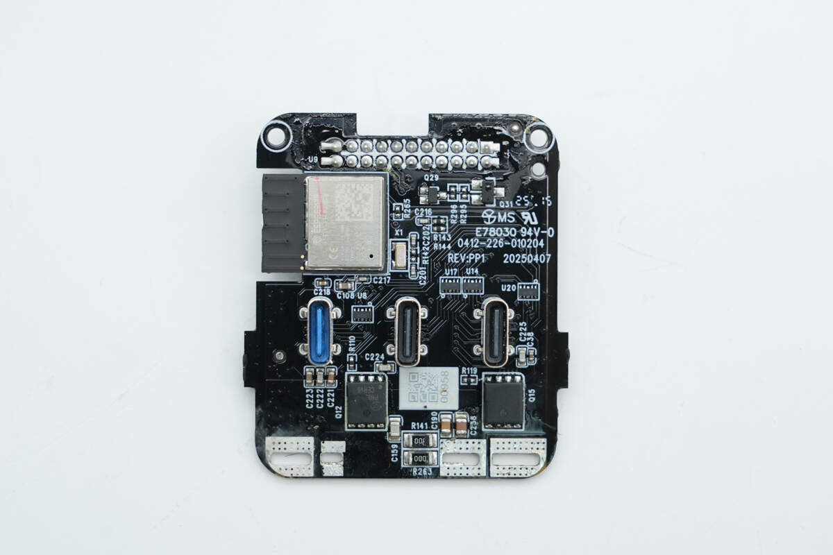
The front of the USB-C interface PCB features VBUS MOSFETs, a TVS diode array, and a wireless communication module.
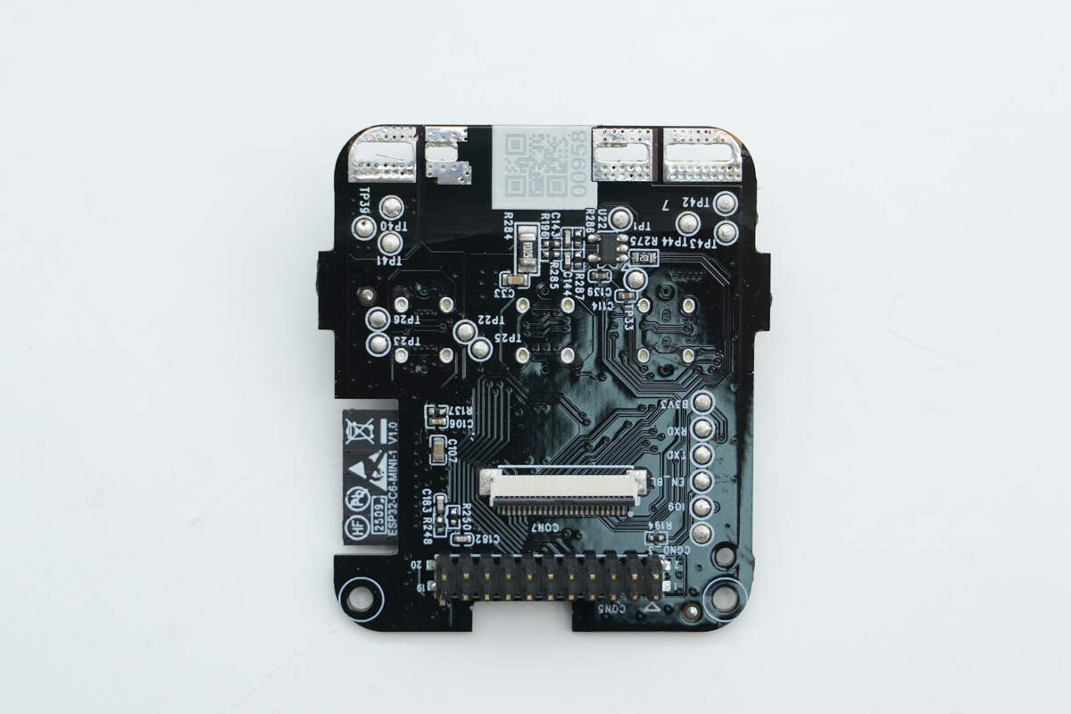
The back side has an operational amplifier, a ribbon cable-connected socket, and pin headers.

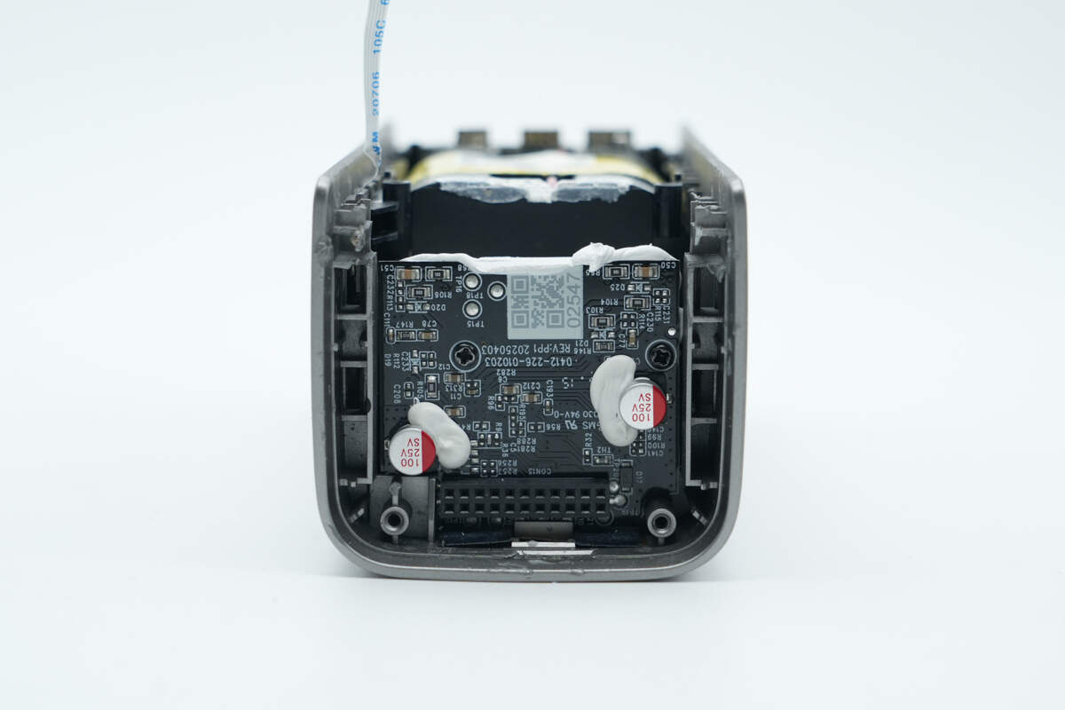
The bidirectional buck-boost charging and discharging control circuit for USB-C2 is designed on a separate PCB. On the front, two solid capacitors are reinforced with adhesive.
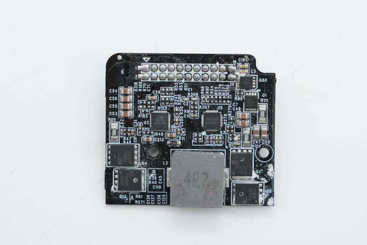
The back side features a buck-boost controller, synchronous buck-boost MOSFETs, a buck-boost inductor, a protocol chip, and a VBUS MOSFET.
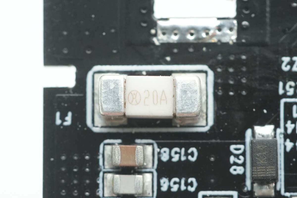
The SMD fuse has a rated current of 20A.

The MCU is from Nations, model N32G452VEL7. This series features a 32-bit ARM Cortex-M4F core, with a maximum operating frequency of 144MHz. It supports floating-point operations and DSP instructions, and is packaged in an LQFP100 form factor.

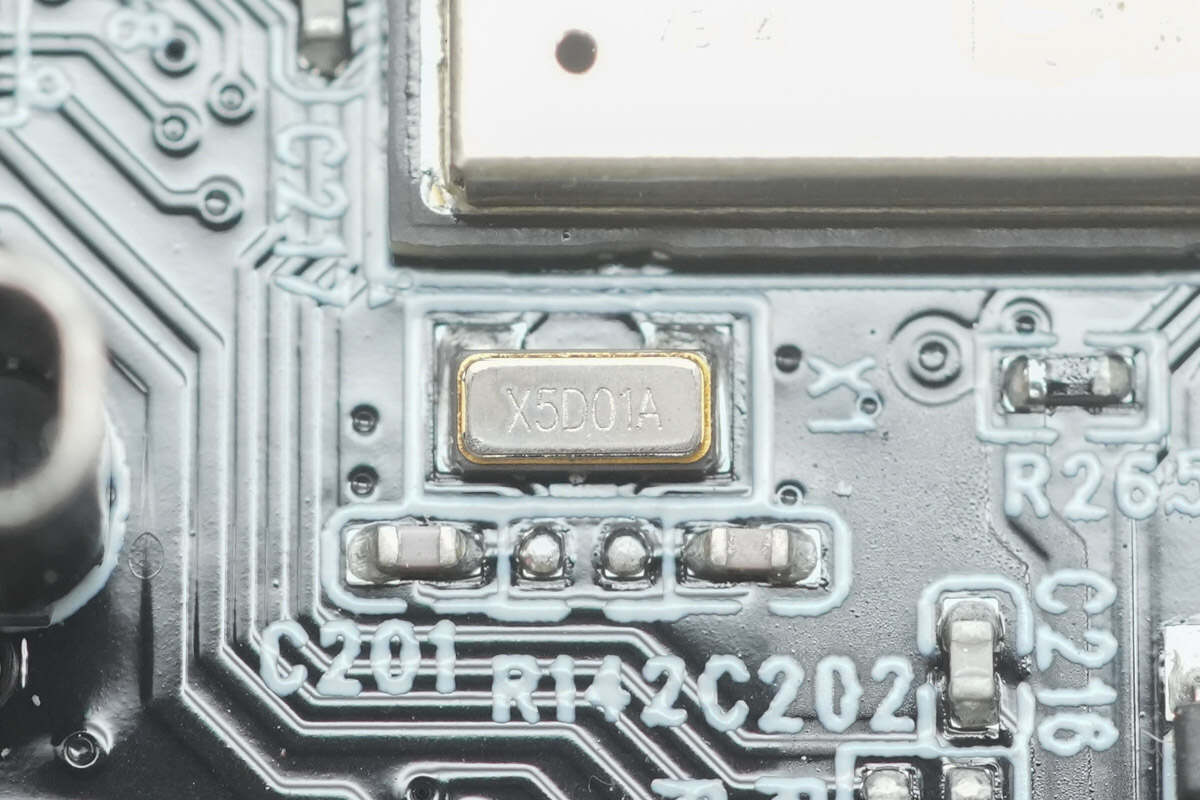
Close-up of the 8.000MHz crystal oscillator.

Close-up of the 32.768kHz crystal oscillator.

The memory is from GigaDevice, model GD25Q256E, with a capacity of 32MB. It supports standard SPI, dual-SPI, and quad-SPI modes. In dual-SPI mode, the data transfer rate can reach 266Mb/s, while in quad-SPI mode, the transfer rate can reach 532Mb/s. It is packaged in a WSON8 form factor.
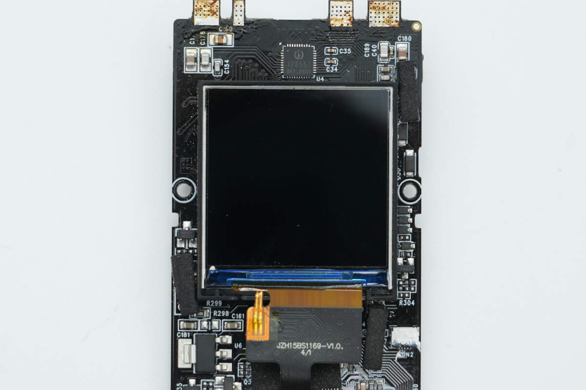
Close-up of the display.

The synchronous buck converter powering the MCU and display is from Silergy, marked with "Iu," model SY8301. It integrates MOSFETs, supports a maximum input voltage of 40V, and provides an output current of 1A.

Close-up of the 3.3μH buck converter inductor.
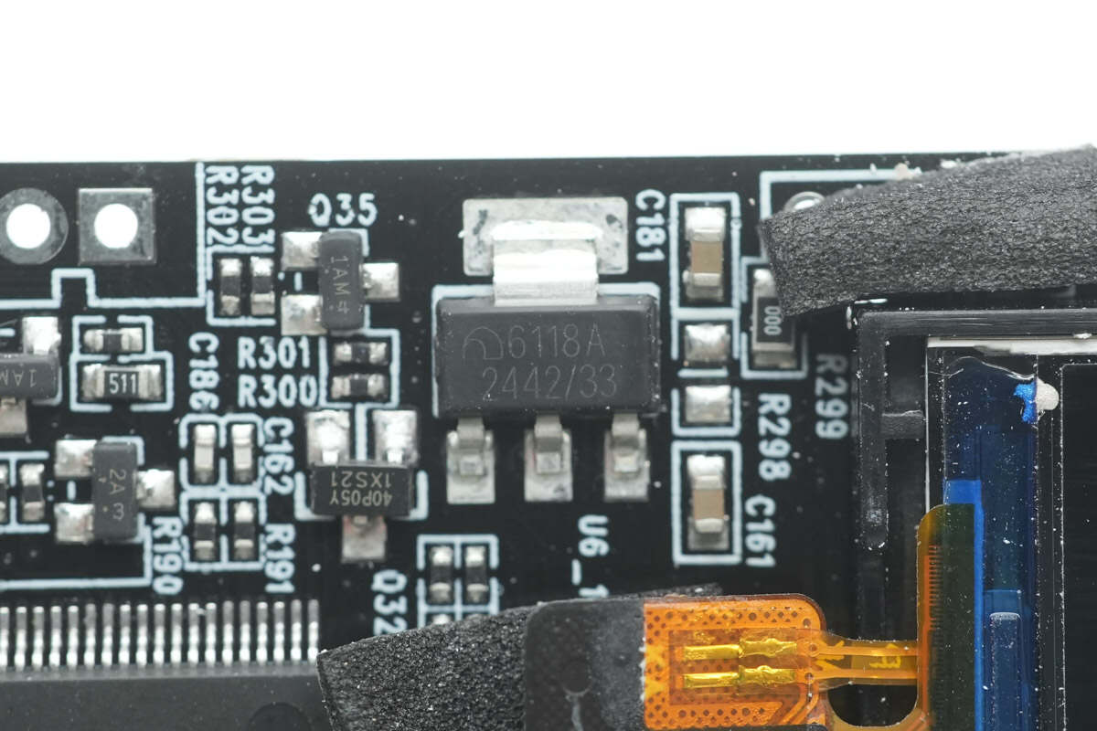
The MicrOne ME6118 series is a high-precision, low-noise LDO voltage regulator capable of providing over 1A of output current. At 1A output current (ME6118 A33), the maximum voltage drop is 1.3V. It comes in an SOT223 package.
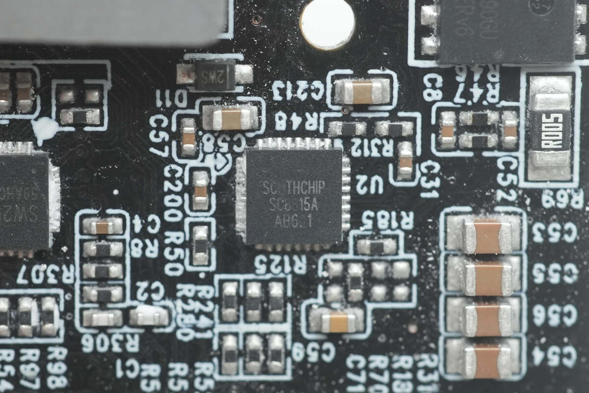
The synchronous buck-boost controller for the USB-C2 port is from SouthChip, model SC8815A. It is an efficient bidirectional synchronous buck-boost controller that supports 1-6 cell battery charging. The chip features an I2C interface and offers complete lithium battery charging management, with control over battery charging current and voltage, reverse discharge output voltage, and input/output current limits via the I2C bus.
It integrates a 10-bit ADC, includes charging status indicators, supports automatic adapter insertion and load insertion detection, and provides under-voltage, over-voltage, and over-current protection, as well as short-circuit and over-temperature shutdown protection. The chip is housed in a QFN32 package and is suitable for PD fast-charging power banks, USB-C hubs, and industrial power applications.
Here is the information about SouthChip SC8815A.
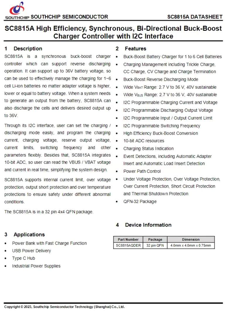
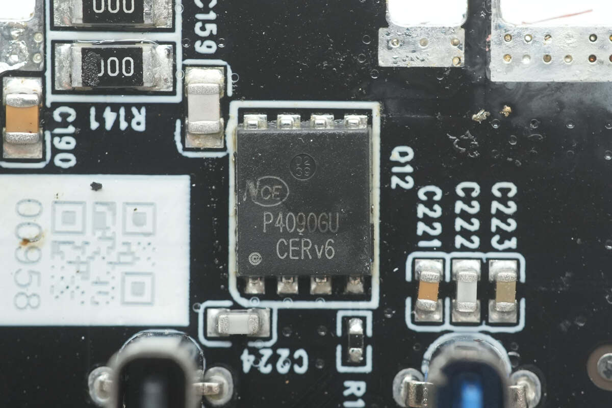
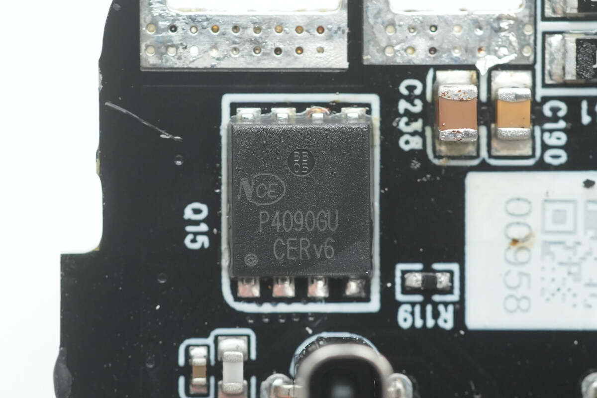
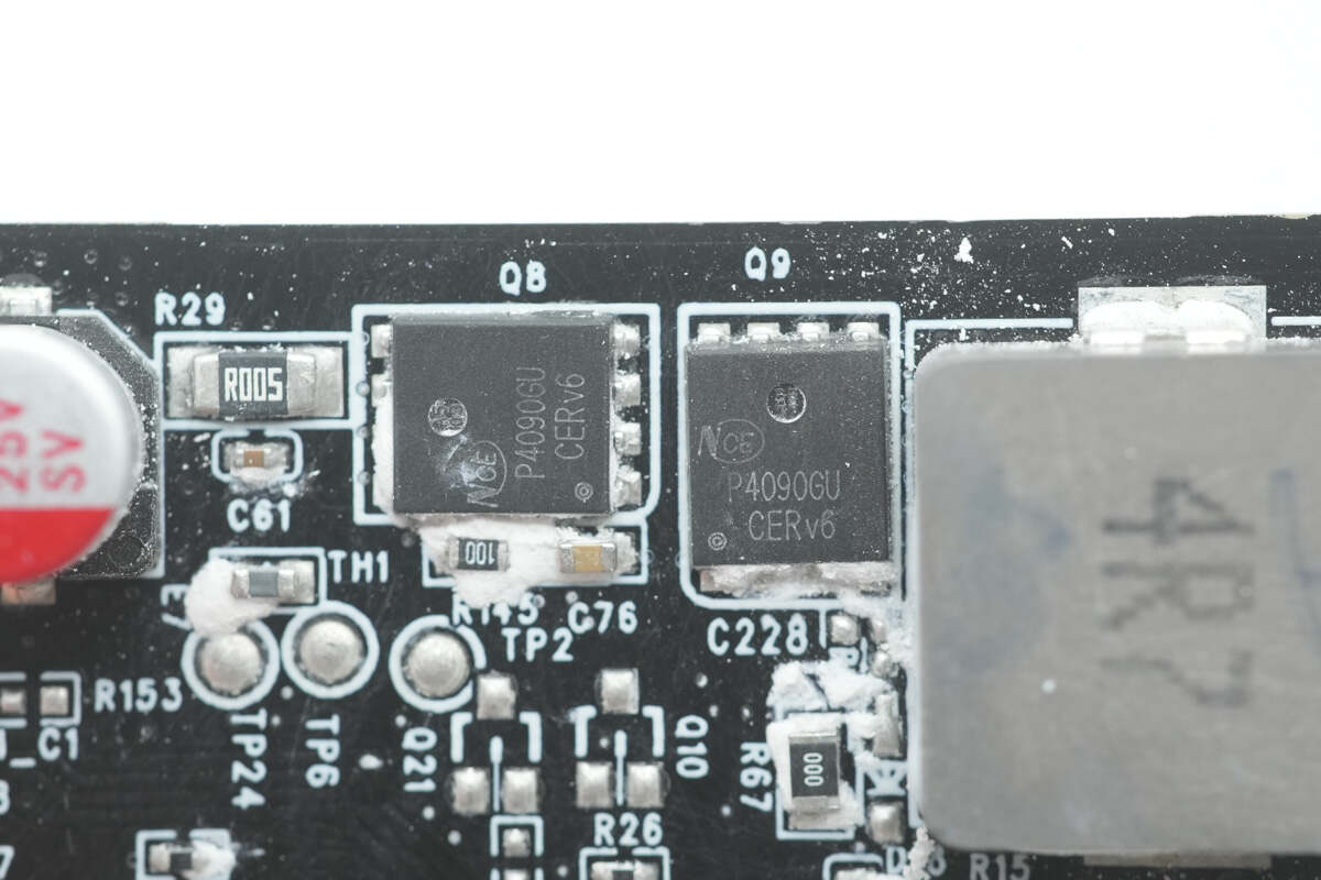
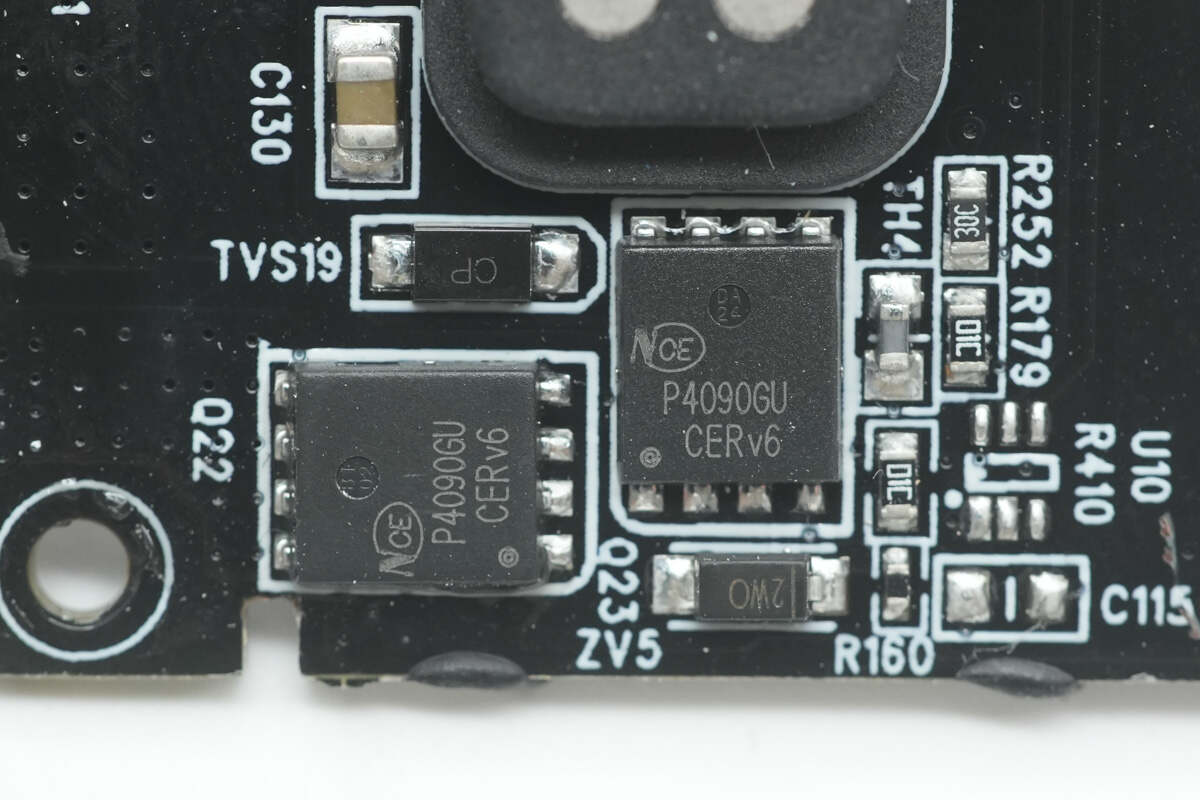
The four synchronous buck-boost MOSFETs are from NCEPower, model NCEP4090GU. They are NMOS type with a voltage rating of 40V, a conduction resistance of 2.2mΩ, and are packaged in a DFN 5*6 form factor.
Close-up of the two additional NCEPower NCEP4090GU synchronous buck-boost MOSFETs.
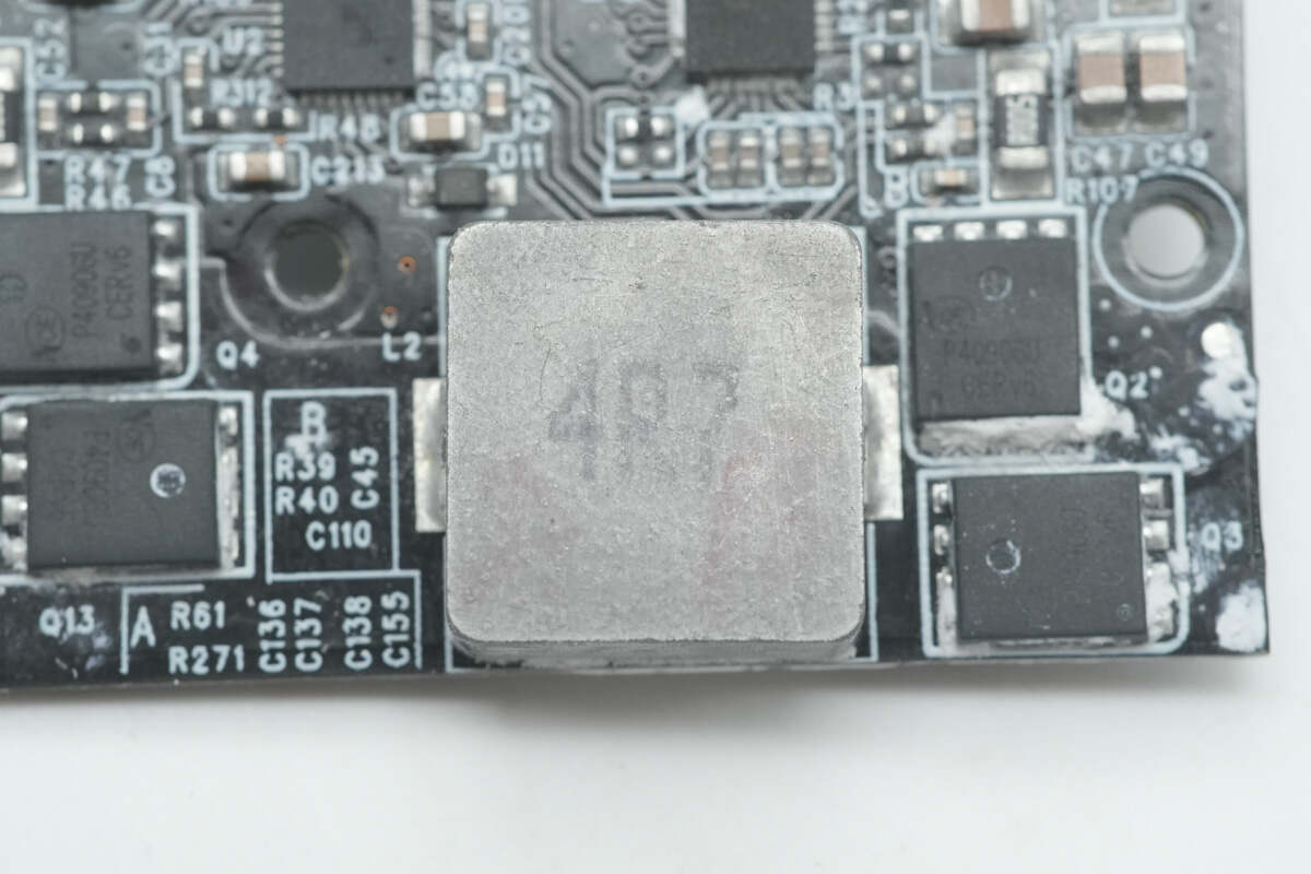
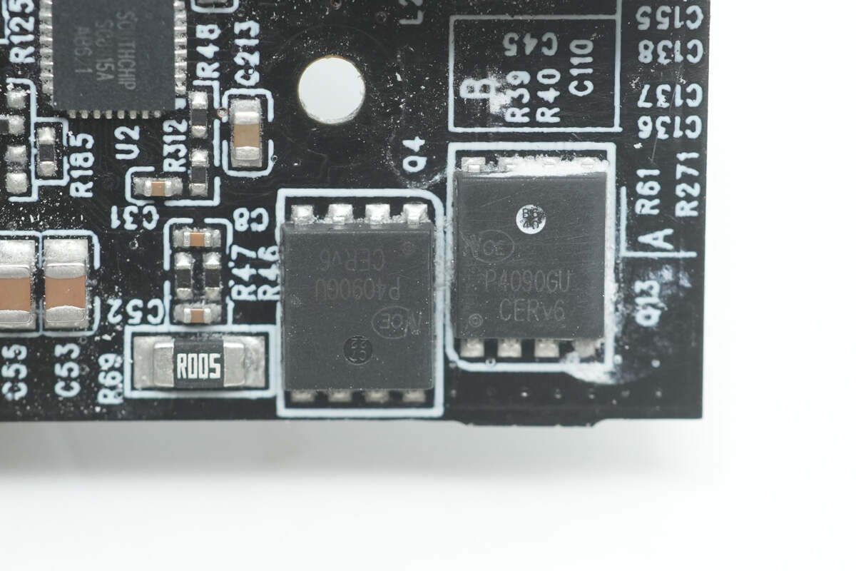
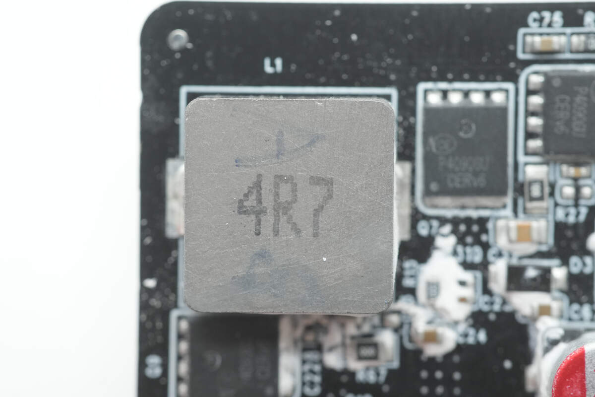
Close-up of the 4.7μH buck-boost inductor.
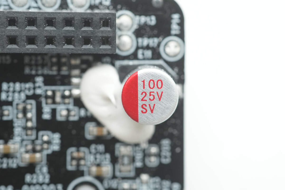
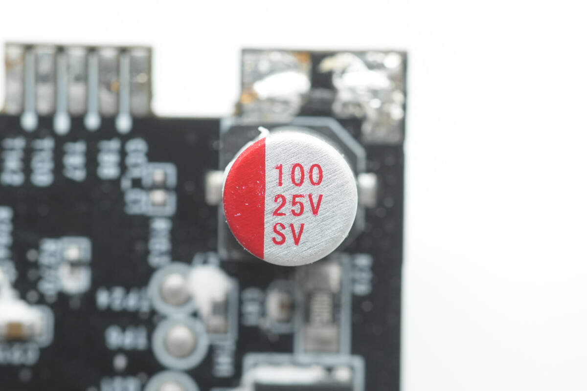
The solid capacitor has a specification of 25V, 100μF.
The other solid capacitor also has a specification of 25V, 100μF.

The protocol chip used is the iSmartWare SW2505H. This is a low-power controller chip that integrates full protocol support, including PD3.1, QC, and UFCS. It is certified with both USB PD3.1 EPR and UFCS standards and supports DRP mode. The chip features an embedded MCU, 16 GPIOs, and C-type support for online upgrades, as well as simulation debugging. It also supports optocoupler/FB control and I2C master-slave mode.
Internally, it integrates a high-efficiency 40MHz Cortex-M0 processor, large capacity Flash and SRAM storage, multiple communication interfaces (I2C, UART), and GPIO and GPADC support. It is designed with low power consumption and supports voltage regulation control in the range of 3.3V to 32V, along with 0.3A to 12A current limiting control. The chip offers various feedback control methods, bus voltage detection, and internally integrates CV, CC loops, as well as VIN, VBUS fast discharge, and NMOS driver circuits, providing highly stable and reliable power management for the system.
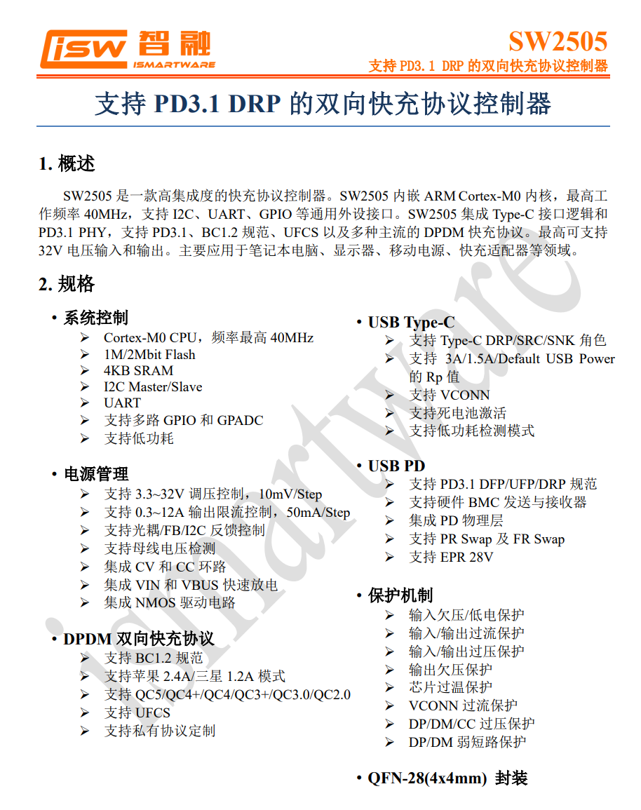
The chip features comprehensive protection mechanisms, including input/output voltage protection, overcurrent protection, overvoltage protection, undervoltage protection, and overtemperature protection, ensuring the safety and stability of the device. It is packaged in a compact QFN-28 (4x4mm) form factor, making it highly compact and suitable for a wide range of applications, including laptops, tablets, power banks, and fast-charging adapters.
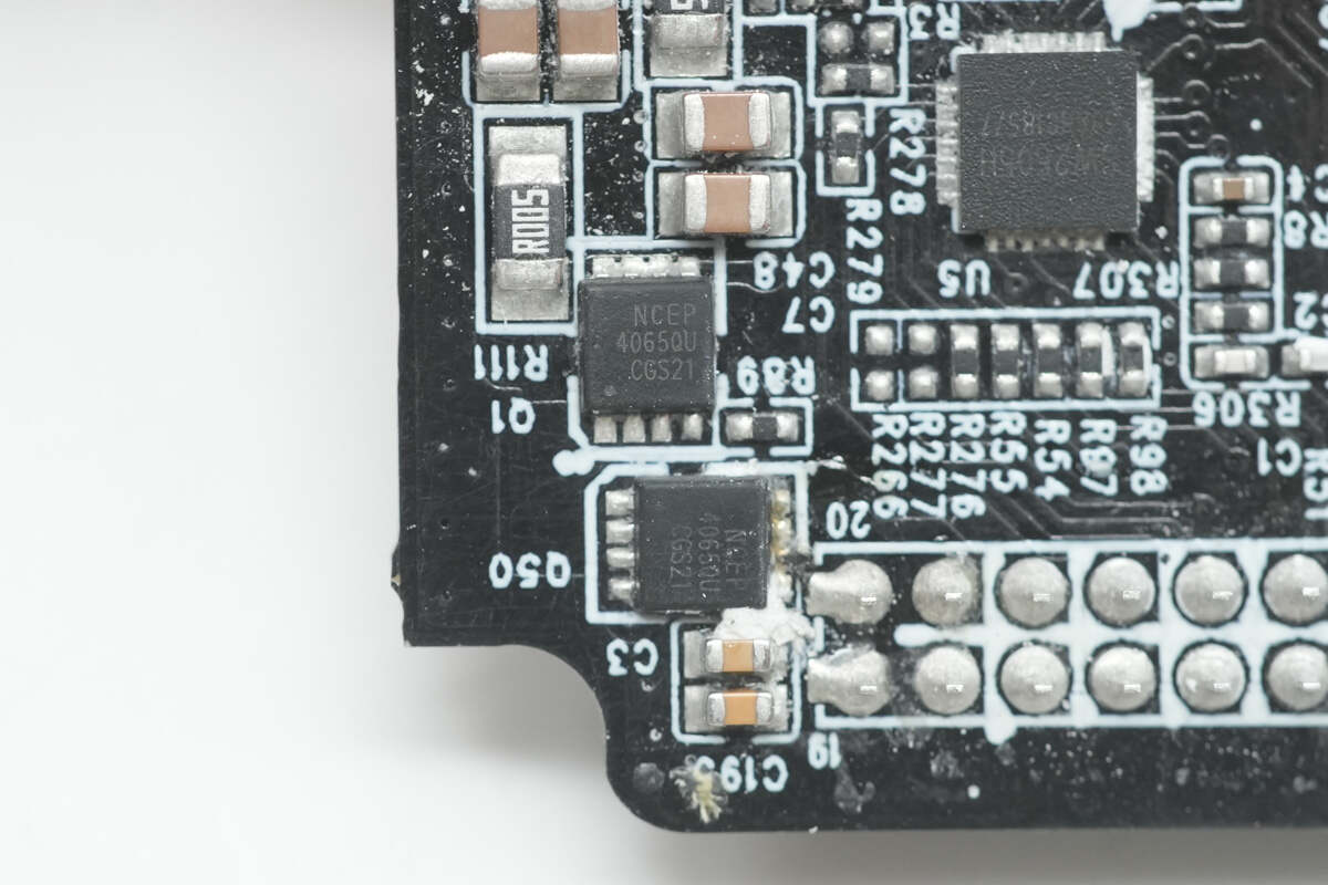
The output VBUS MOSFETs for USB-C2 are also from NCEPower, model NCEP4065QU. These are NMOS transistors with a voltage rating of 40V, a conduction resistance of 2.2mΩ, and are packaged in a DFN 3.3*3.3 form factor.
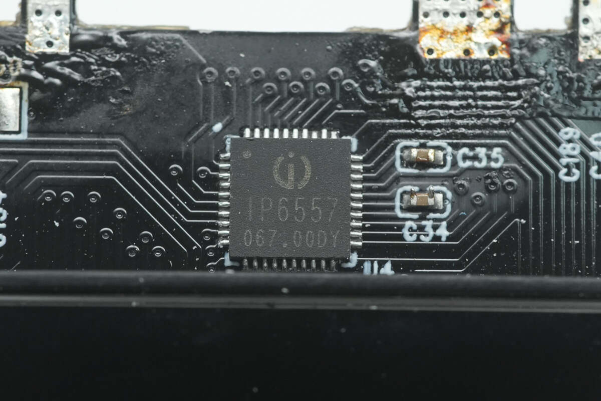
The buck-boost SOC used for the USB-C3 and USB-C4 ports is from Injoinic, model IP6557. This chip integrates a buck-boost controller and control functions for the path NMOS, supporting fast charging protocols such as QC2.0/3.0/3+/4+/5, FCP, HSCP, AFC, MTK, UFCS, and USB-C PD3.1/PPS/ERP28V output. With just one inductor and a power MOSFET, it enables a fast-charging solution with buck-boost functionality, effectively reducing the overall solution size and lowering BOM costs, providing a complete power solution for automotive chargers.
The integrated buck-boost controller can provide a maximum output power of 140W (28V 5A) and supports NTC board-level temperature detection, intelligently adjusting output power based on temperature. It also features a 14-bit ADC for accurate measurement of input/output voltage and current, as well as IO voltage.

The IP6557 fast-charging output features CV/CC characteristics. When the output current is less than the set value, it operates in CV mode, maintaining a constant output voltage. When the output current exceeds the set value, it switches to CC mode, where the output voltage decreases.
Additionally, the IP6557 integrates multiple protection functions, including input overvoltage, undervoltage protection, output overvoltage, undervoltage, overcurrent, short circuit, and overtemperature protection, ensuring safe and stable operation. It is packaged in a QFN40 (5mm x 5mm) form factor.

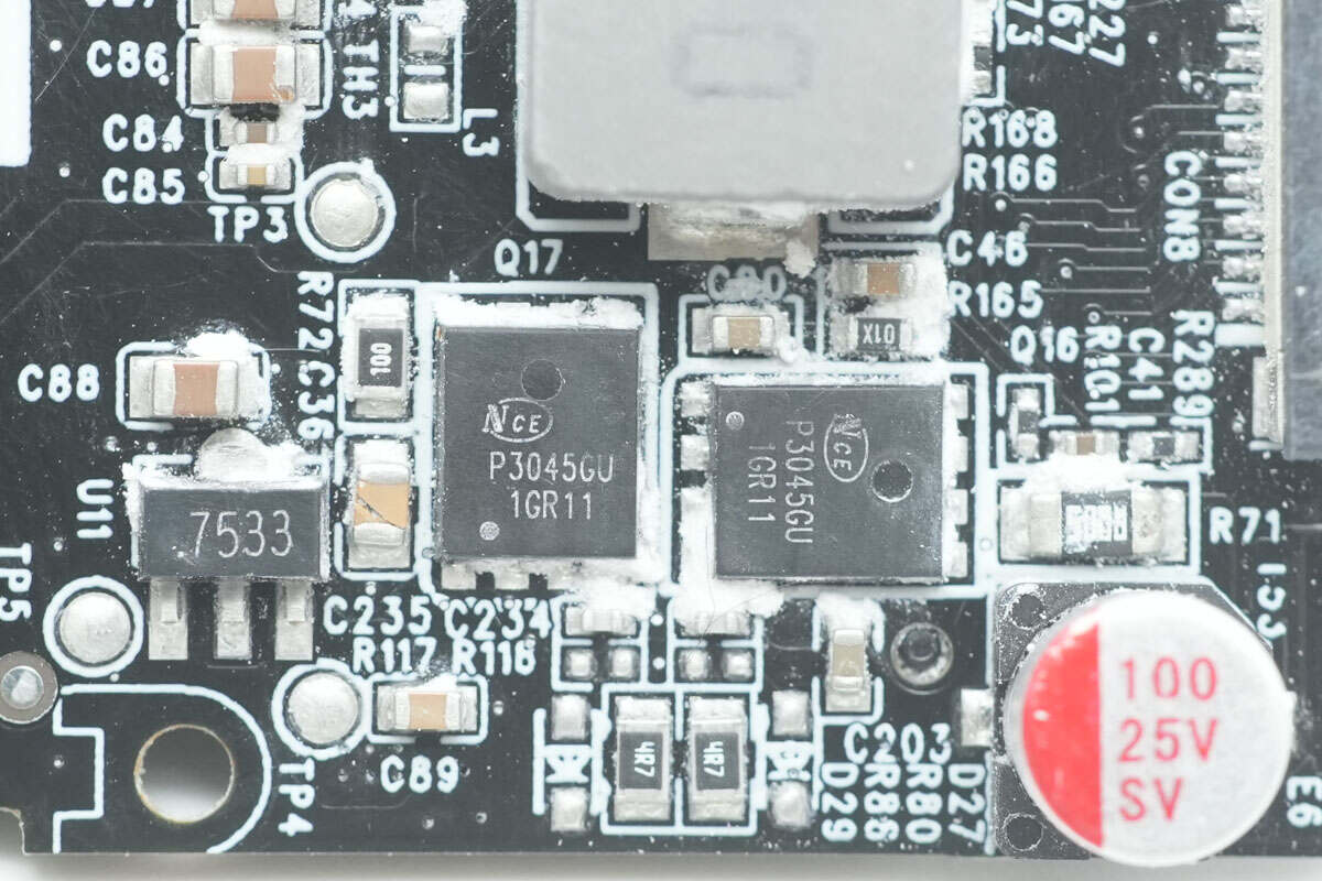
The four synchronous buck-boost MOSFETs are from NCEPower, model NCEP3045GU. These are NMOS transistors with a voltage rating of 30V, a conduction resistance of 5.8mΩ, and are packaged in a DFN 5*6-8L form factor.
Close-up of the two additional NCEPower NCEP3045GU synchronous buck-boost MOSFETs.
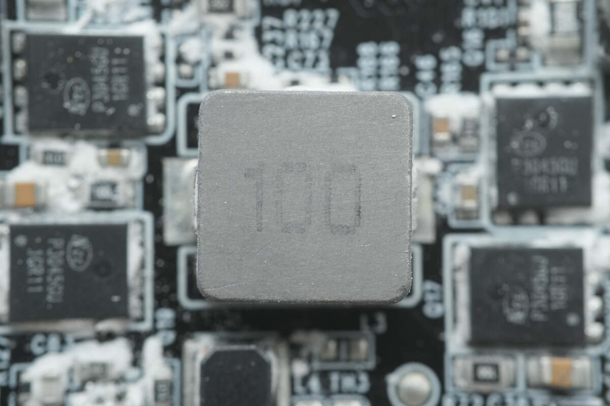
Close-up of the 10μH buck-boost inductor.

Close-up of the voltage regulator chip marked with "7533."
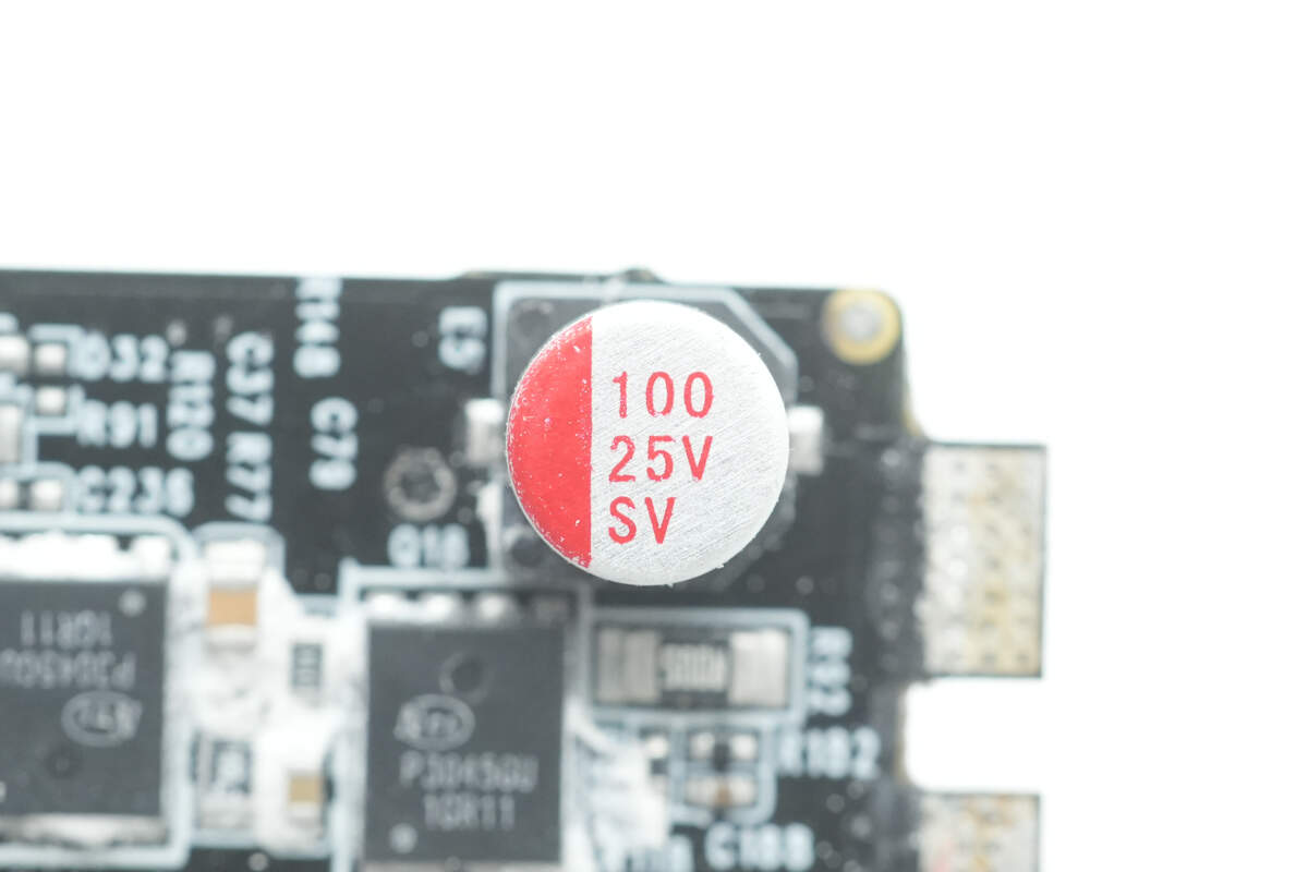
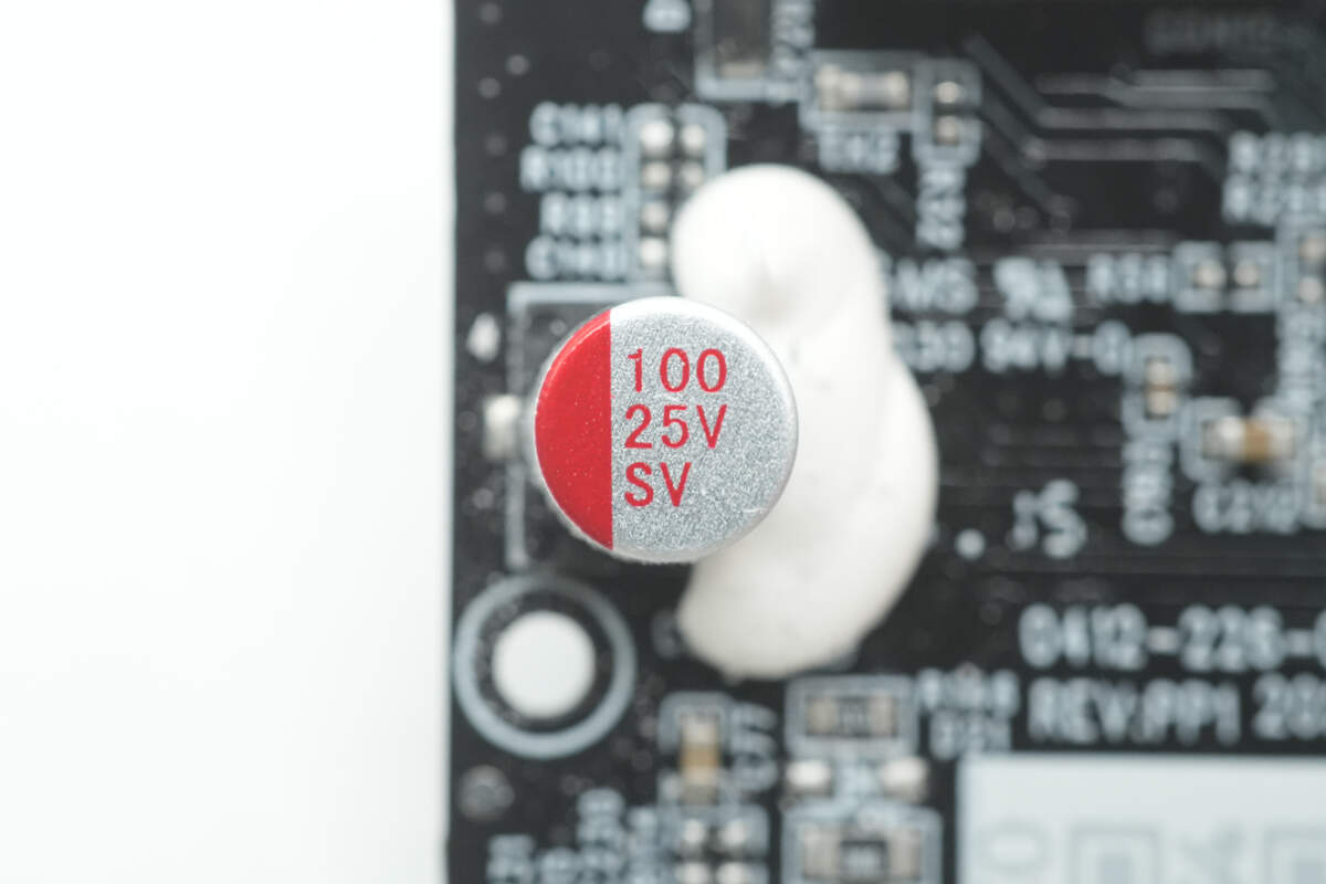
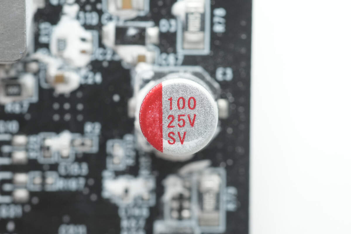
The solid capacitor has a specification of 25V, 100μF.
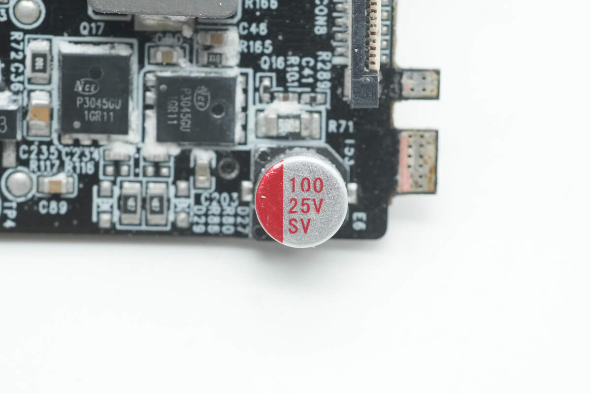
The other solid capacitor also has a specification of 25V, 100μF.
The output VBUS MOSFET for USB-C3 is from NCEPower, model NCEP4090GU.
The output VBUS MOSFET for USB-C4 is also from NCEPower, model NCEP4090GU.

Close-up of the Belling BL3701 low-noise operational amplifier.
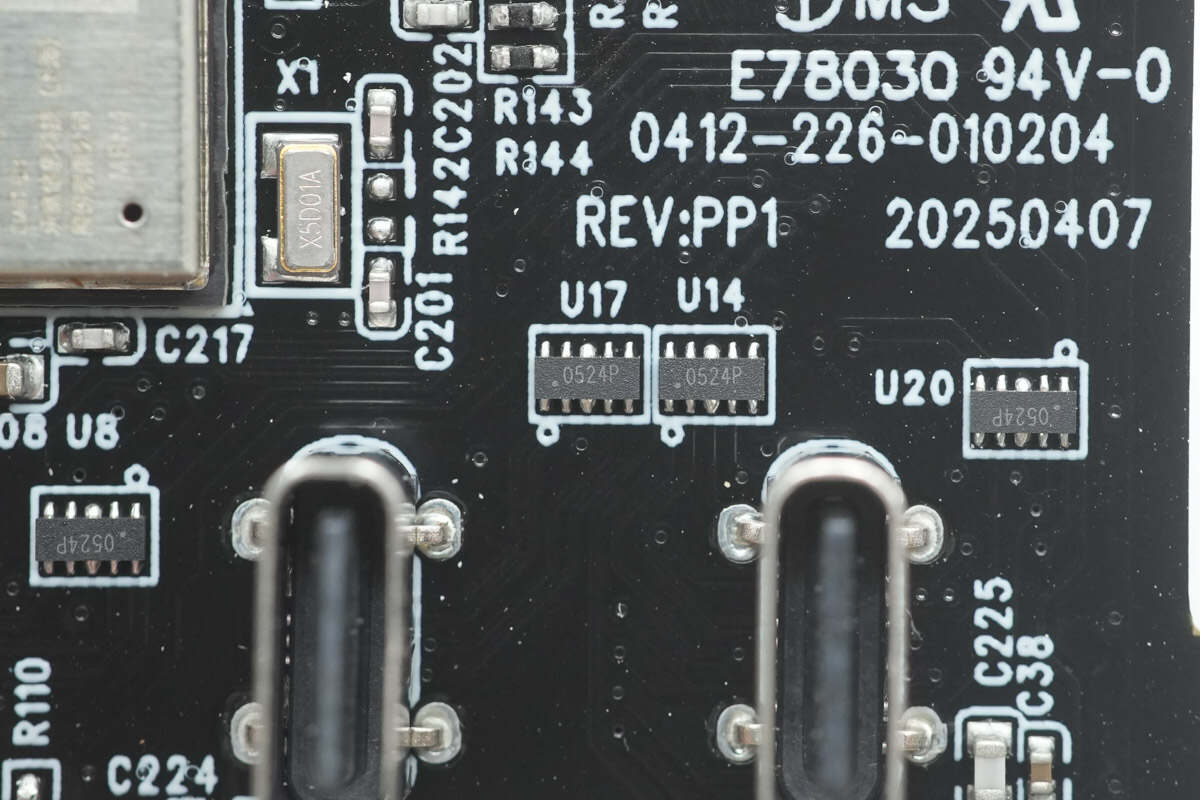
Each USB-C interface is equipped with a TVS array marked with "0524P" for electrostatic discharge protection.

The wireless connectivity module is from ESPRESSIF, specifically the ESP32-C6-MINI-1 module. It supports 2.4G Wi-Fi 6 and Bluetooth 5, and is a compact module with the ESP32-C6 series chip. It features a RISC-V 32-bit single-core processor, with a maximum selectable on-board flash of 8MB. The module provides 22 GPIO pins and uses an integrated PCB antenna.
Close-up of the 32.768KHz crystal oscillator.

The PCB with the three function buttons is connected to the top PCB via a ribbon cable.
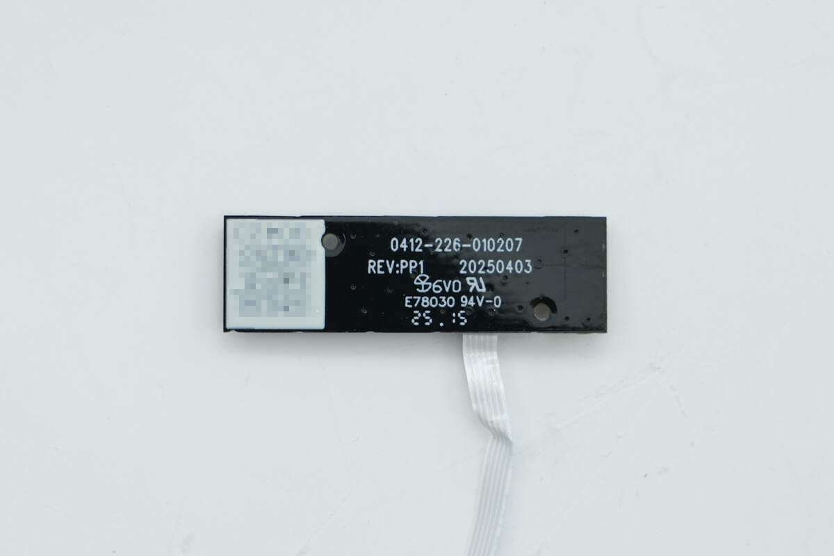
The backside has no components.

The bidirectional buck-boost charging and discharging control circuit for the USB-C1 built-in cable is also designed on a separate PCB. On the front, it features synchronous buck-boost MOSFETs, a buck-boost inductor, solid-state capacitors, and VBUS MOSFETs.
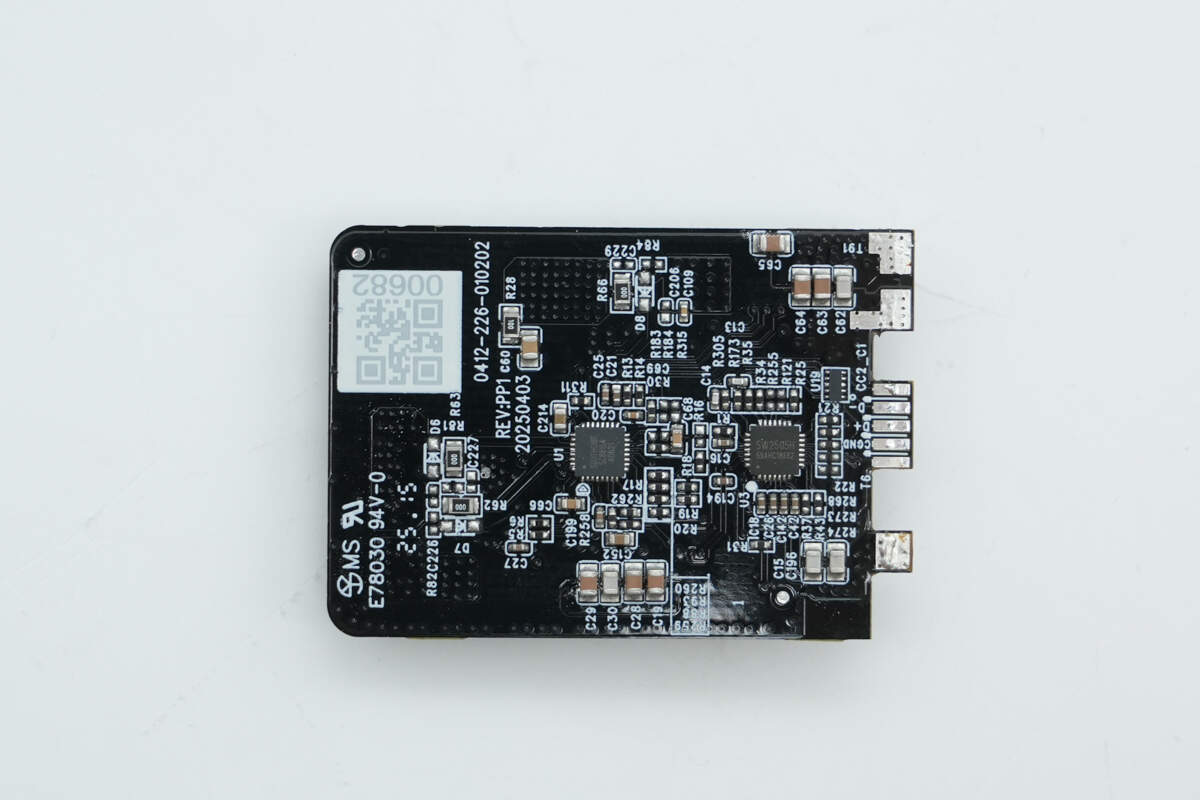
The backside of the PCB contains the synchronous buck-boost controller and the protocol chip.
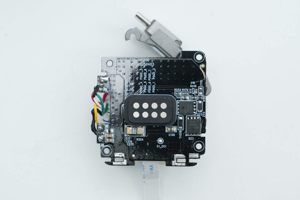
The Pogopin input contacts are designed on a separate PCB, and the front side also features two VBUS MOSFETs.
The backside is connected to a ribbon cable and also features the design for the USB-C1 retractable cable module.
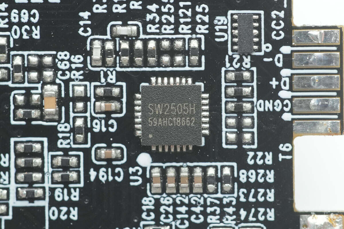
The protocol chip used for the USB-C1 built-in cable is also the iSmartWare SW2505H.
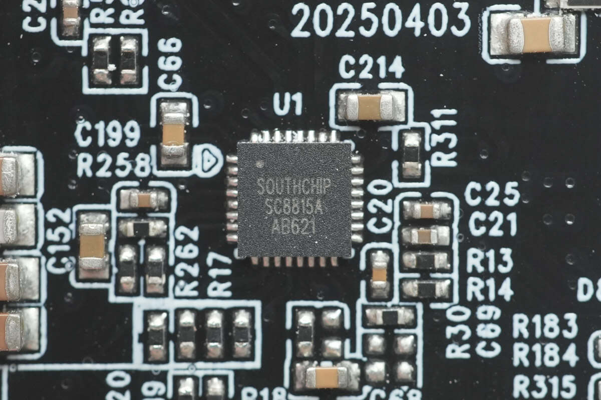
The synchronous buck-boost controller used is the SouthChip SC8815A.
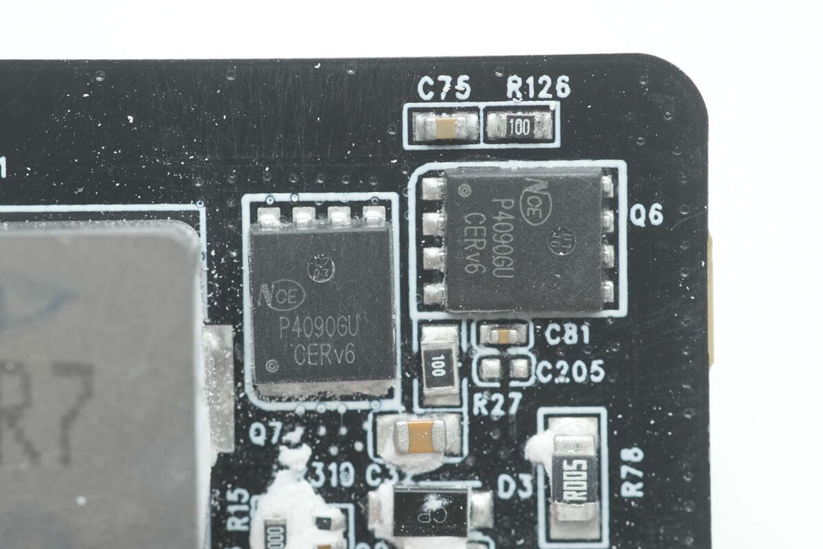
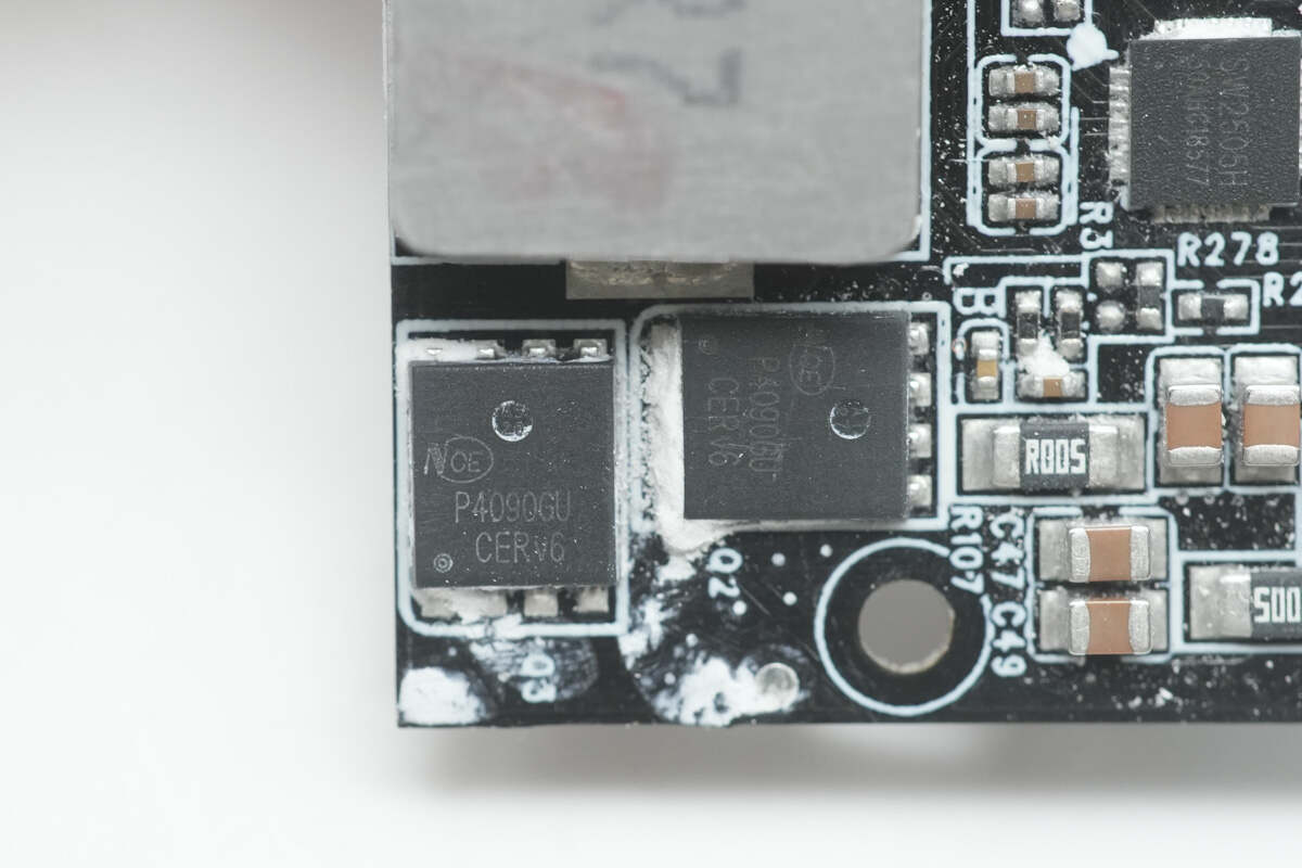
The synchronous buck-boost MOSFETs used are from NCEPower, model NCEP4090GU.
Close-up of the two additional NCEPower NCEP4090GU synchronous buck-boost MOSFETs.
Close-up of the 4.7μH buck-boost inductor used in the design.
The solid capacitor has a specification of 25V, 100μF.
The other solid capacitor also has a specification of 25V, 100μF.

The VBUS MOSFETs are also from NCEPower, model NCEP4065QU.
The two VBUS MOSFETs on the other PCB are also from NCEPower, model NCEP4090GU.

Disassemble the USB-C1 retractable cable module.
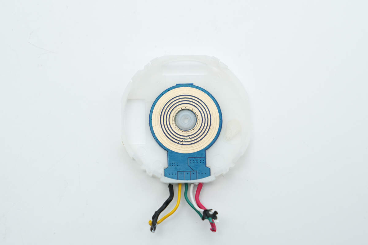
Close-up of the PCB slip ring.
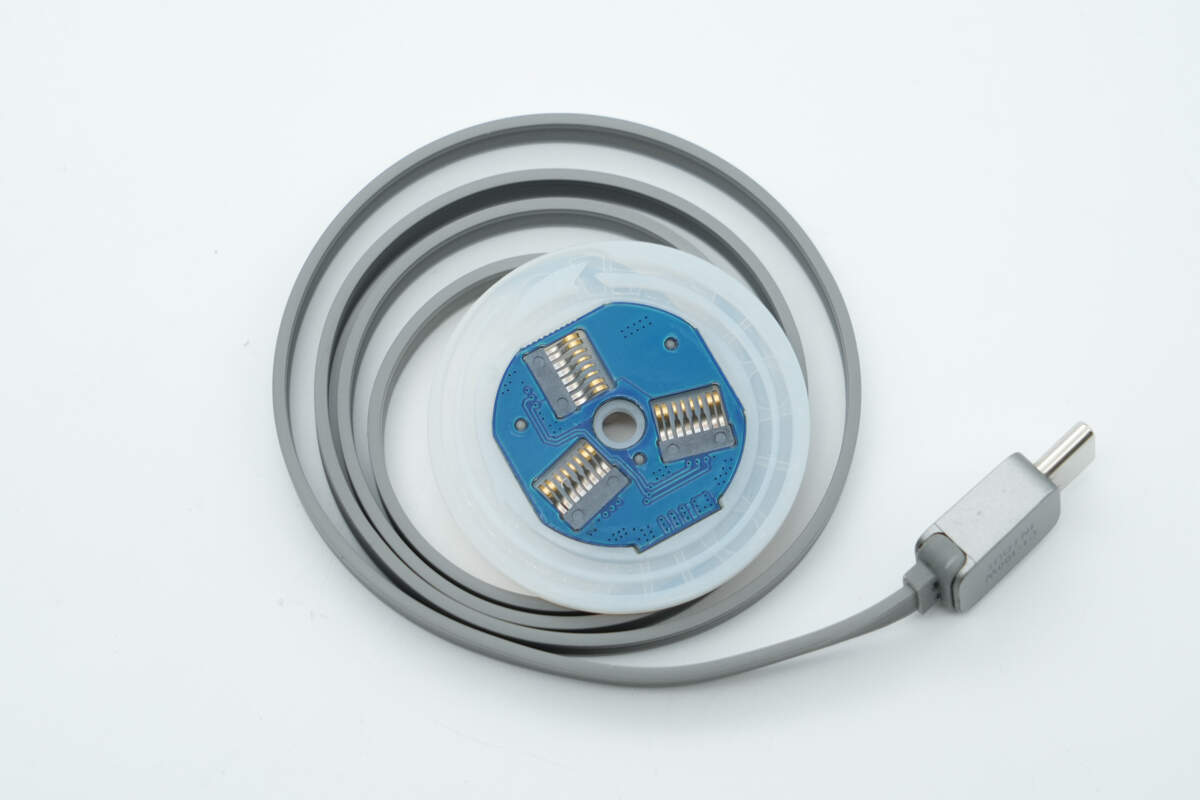
The retractable cable reel is equipped with three brushes to enhance the current-carrying capacity.
Well, those are all components of the EcoFlow RAPID Pro 230W 20,000mAh Power Bank with Built-in Cable.
Summary of ChargerLAB

Here is the component list of the EcoFlow RAPID Pro 230W 20,000mAh Power Bank with Built-in Cable for your convenience.
It boasts a sleek, futuristic design. The smart display offers a variety of functions, including customizable emojis, screen display time settings, remaining battery life, and fast-charging status for each port. Additionally, it can connect to an app, enabling control via your phone, bringing the smart interaction experience to the next level.
It comes with a 60cm long USB-C retractable cable and three USB-C ports. It supports 100W bidirectional fast charging, 120W Pogopin charging, and dual USB-C combined charging. Compatible with protocols like UFCS, SCP, and PPS, it can deliver up to 230W of total power, meeting the fast charging needs of up to four devices simultaneously.
After taking it apart, we found that the battery pack uses four SunPower INR21700-5000 lithium batteries, with a total capacity of 20,000mAh, and has passed CCC certification. It is equipped with the Cellwise CW1244 lithium battery protection solution, as well as thermistors for temperature monitoring. The battery health and temperature are visually displayed, ensuring safer and more reliable usage.
The USB-C1 retractable cable and USB-C2 port use the SouthChip SC8815A buck-boost controller paired with the iSmartWare SW2505H protocol chip for bidirectional fast charging. The other two USB-C ports deliver 65W output via the Injoinic IP6557 buck-boost SOC. Additionally, the module features a Nations MCU, GigaDevice memory, and Silergy step-down power supply solutions. The module is secured with screws and adhesive and is equipped with effective insulation and heat dissipation designs, showcasing high-quality craftsmanship.
Related Articles:
1. Teardown of Nintendo Switch 2 Original 60W PD Fast Charger (Japan Version)
2. Teardown of Google 25W Qi2.2 Magnetic Wireless Charger (GH5UG)
3. Teardown of Apple 25W Qi2.2 + MagSafe Charger A3502 (HK Version)