Introduction
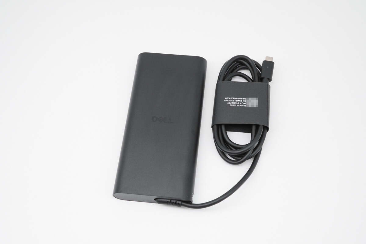
We recently received a Dell 280W GaN power adapter. With an impressive 280W output, it ensures stable operation and battery charging for models such as the Dell Pro Max 16 Plus and Pro Max 18 Plus.
A key highlight is its support for the USB PD 3.1 fast-charging standard, delivering up to 48V/5A (240W) fast charging. This capability meets the high-speed charging requirements of high-performance laptops, power banks, drones, and other devices. Below, we will perform a teardown to examine its internal design and components.
Product Appearance

It is packaged in a kraft paper box with DELL printed on it.
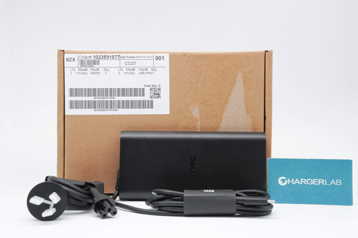
The power cable and adapter feature a split-type design.
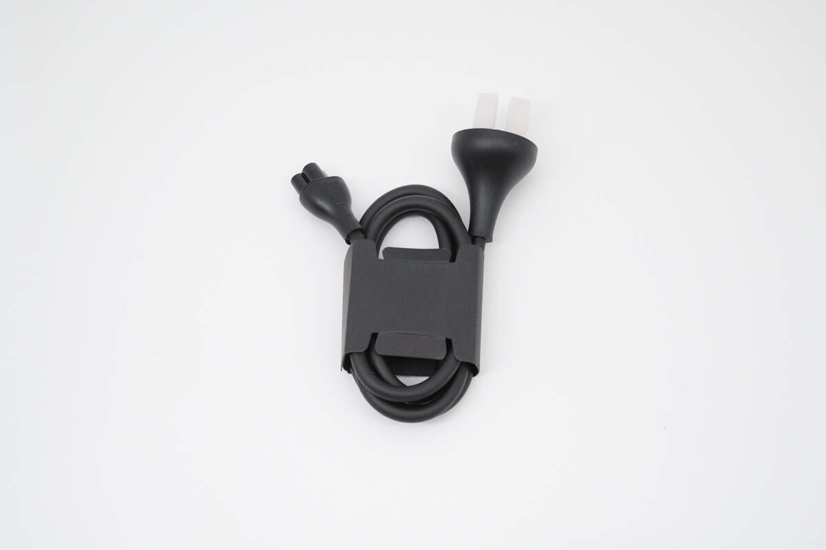
The power cable is secured with a paper loop. The plug is protected by a white plastic cover.
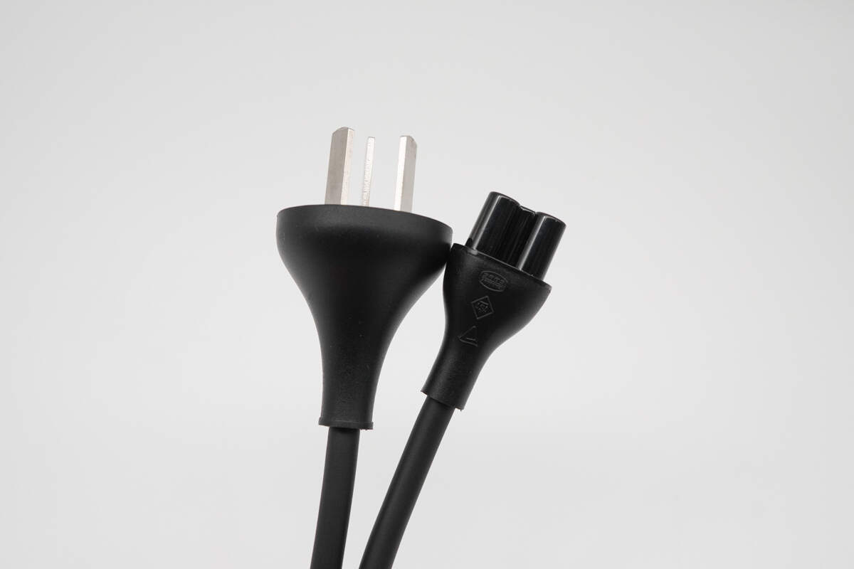
The power cable features a three-prong plug on one end and a cloverleaf connector on the other.
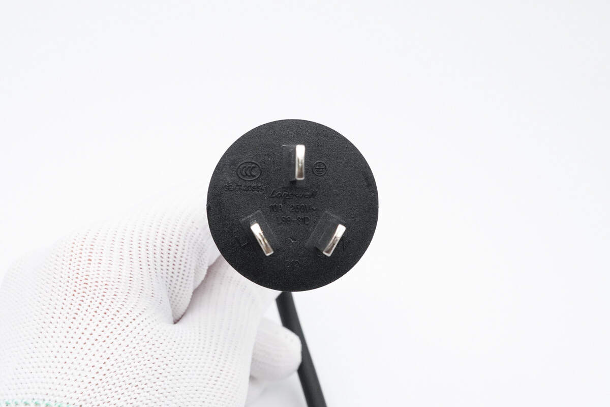
The cable is manufactured by Longwell, rated at 10A 250V~, and certified by CCC.
The adapter has a matte, fingerprint-resistant surface with curved sides.
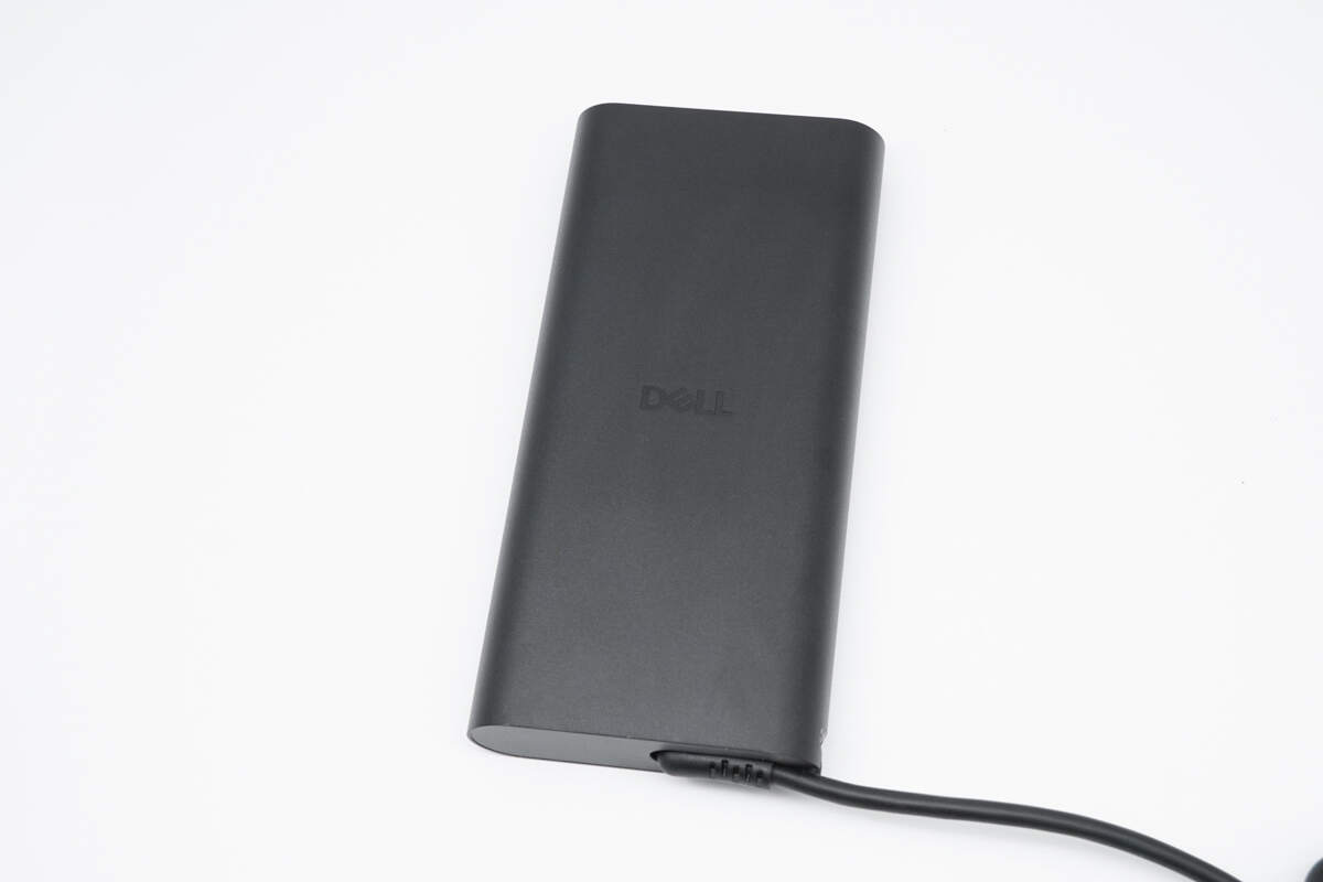
The center features the DELL logo.
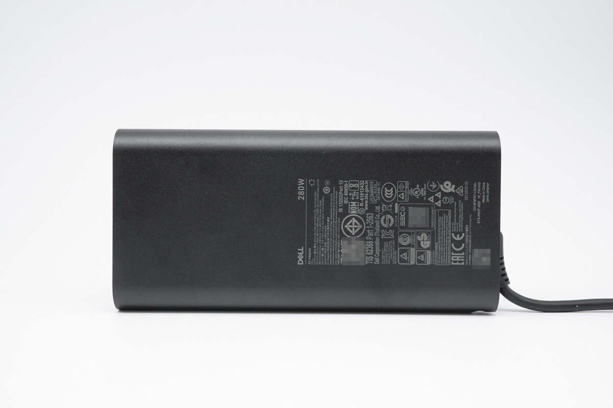
The back is printed with specification information.

It is certified by CCC, KC, CE, EAC, CP, PSE, GS, UL, NOM, NYCE, and several other standards, making it compatible for use in the vast majority of countries and regions worldwide.
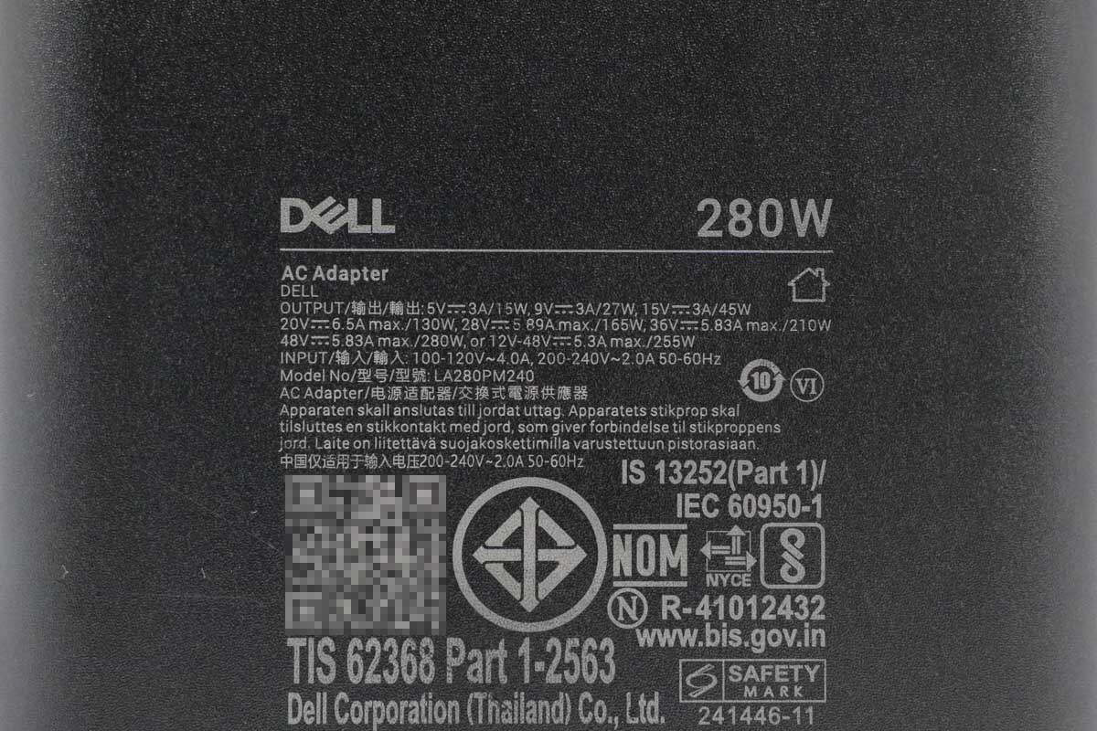
Model: LA280PM240
Input: 100-120V~4A, 200-240V~2A 50/60Hz
Output: 5V 3A, 9V 3A, 15V 3A, 20V 6.5A, 28V 5.89A, 36V 5.83A, 48V 5.83A, 12-48V 5.3A
Certified with VI-level energy efficiency.

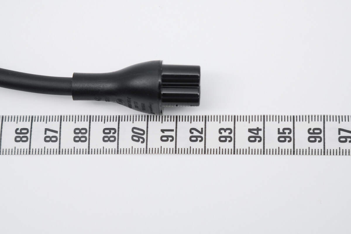
One end of the device is equipped with a cloverleaf connector.

The other end features an output cable groove, with the cable reinforced for bend resistance.
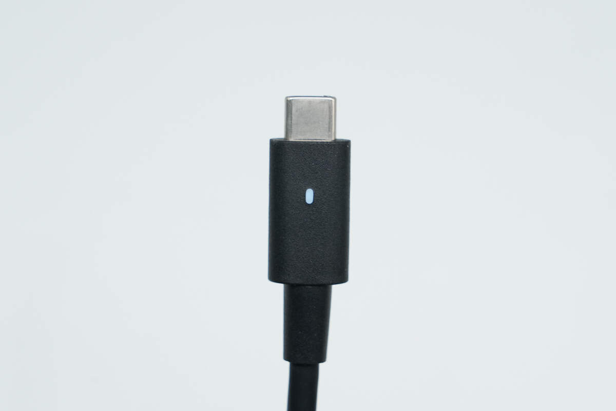
The USB-C connector has an LED indicator that emits a soft blue light when powered on.
The length of the power cord is about 92 cm (36.22 inches).
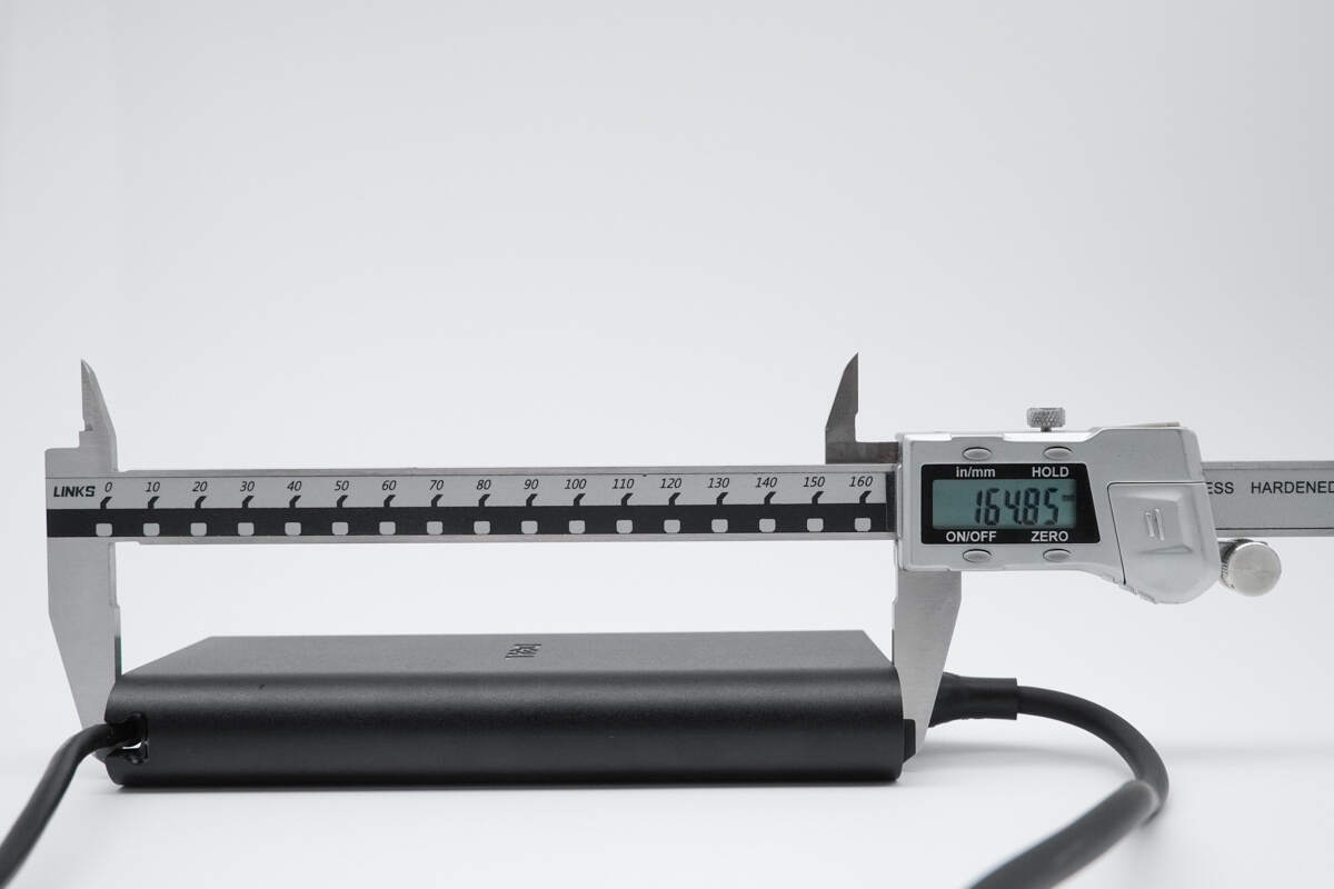
The length of the adapter is about 164.85 mm (6.49 inches).

The width is about 78.23 mm (3.08 inches).

The thickness is about 23.51 mm (0.93 inches).
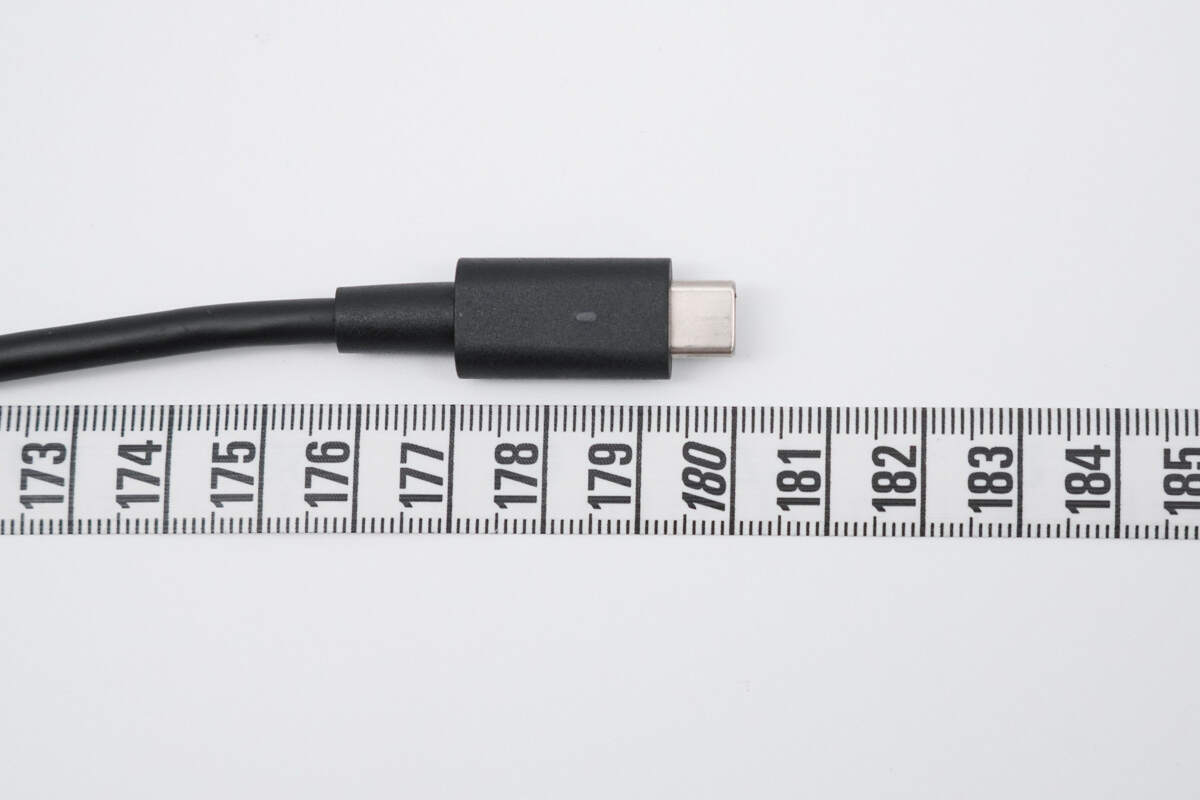
The length of the output cable is about 180 cm (70.87 inches).
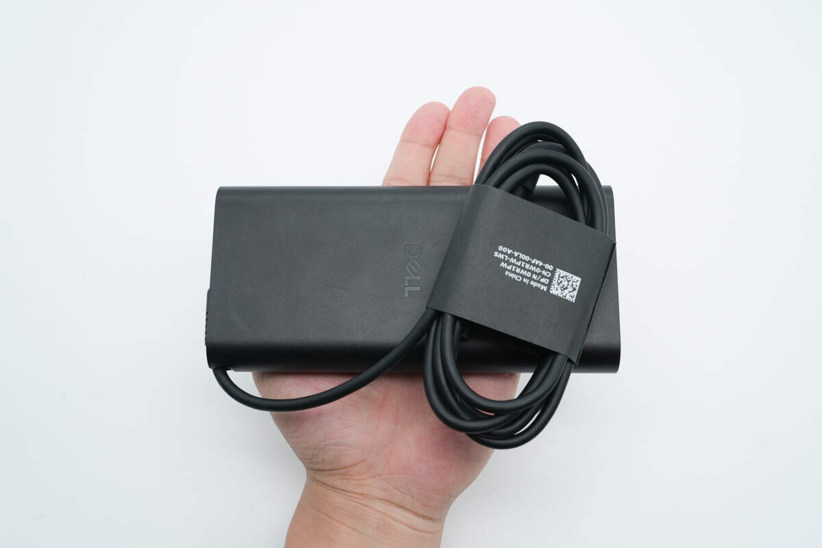
That's how big it is in the hand.
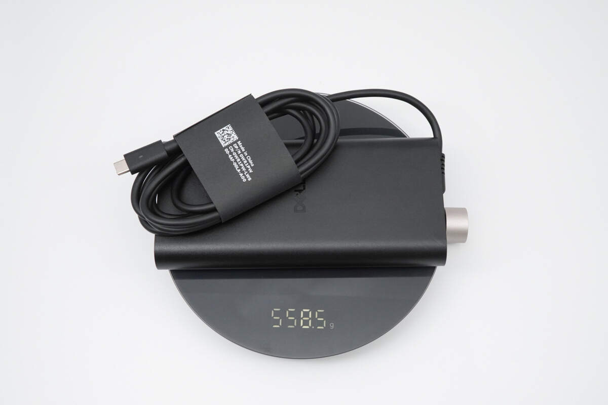
The weight is about 559 g (19.72 oz).
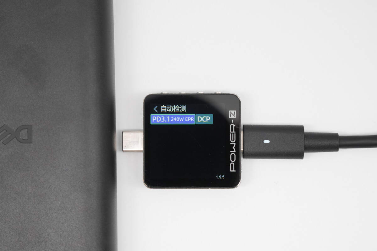
ChargerLAB POWER-Z KM003C shows it supports PD3.1 and DCP protocols.
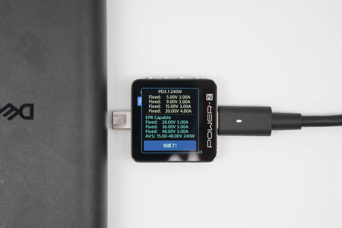
It has seven fixed PDOs of 5V3A, 9V3A, 15V3A, 20V4.8A, 28V5A, 36V5A, and 48V5A. It also has one set of AVS, which is 15-48V 240W.

When used to charge the Aohi 240W PD3.1 power bank, the measured charging power was approximately 136W, successfully activating PD3.1 28V 5A 140W fast charging.
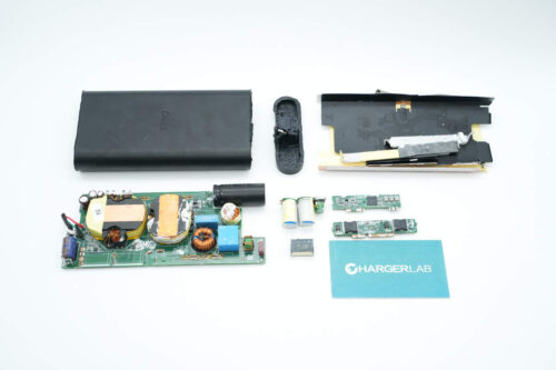
Teardown
Next, let's take it apart to see its internal components and structure.
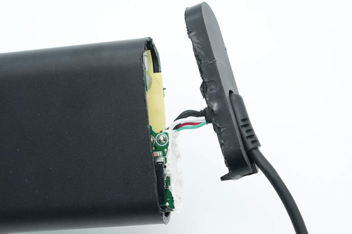
Remove the casing of the output end. The output wires are connected using crimp terminals with soldering.
Disassemble the outer casing on the other end to remove the PCBA module.
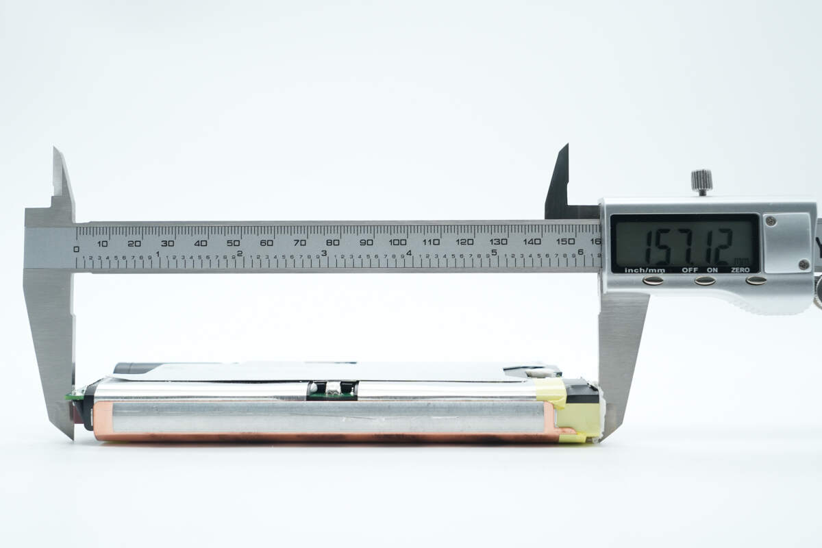
The length of the PCBA module is about 157.12 mm (6.19 inches).

The width is about 73.35 mm (2.89 inches).

The thickness is about 18.57 mm (0.73 inches).
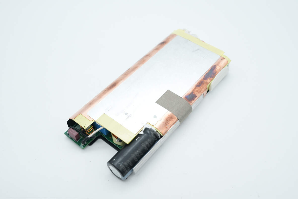
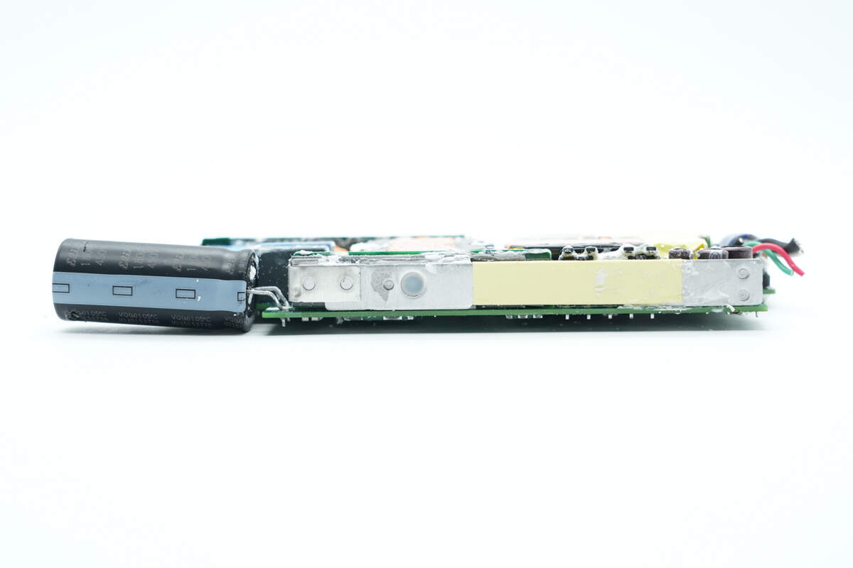
The PCBA module is covered with a copper heatsink and an aluminum plate.

The inner side of the heatsink is lined with insulating tape and a Mylar sheet.

The front side of the PCBA module is filled with white adhesive.

The back side is also covered with a thermal pad and treated with adhesive.
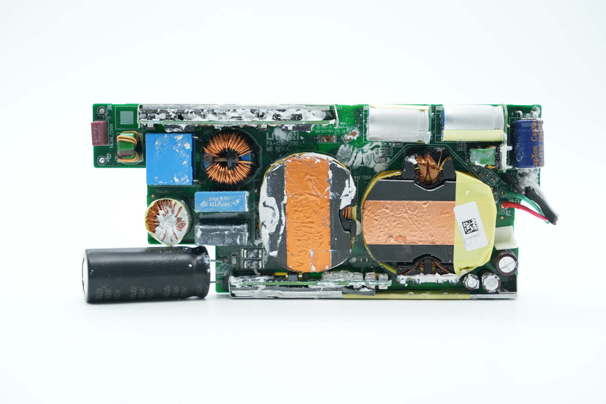
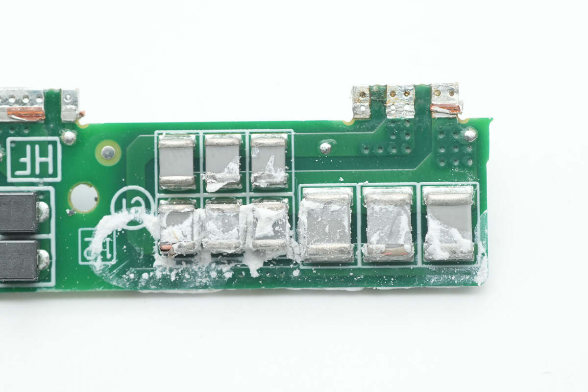
Remove the white adhesive. The front side reveals components such as a time-delay fuse, common mode chokes, filter capacitors, a PFC boost inductor, and a transformer.

The back side contains components such as bridge rectifiers, a master control chip, HFB half-bridge MOSFETs, synchronous rectifiers, a synchronous buck converter, and a protocol chip.

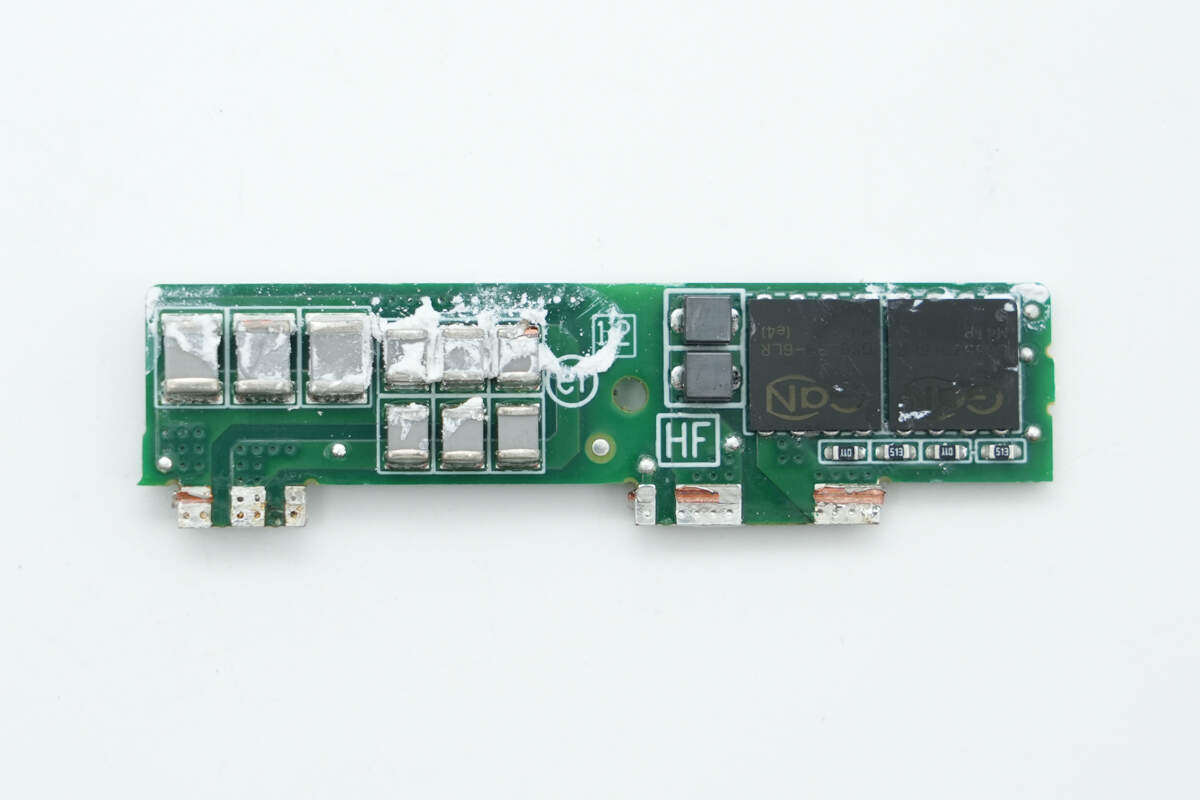
An active rectification PCB is soldered on the side.

Remove the active rectification PCB. The front side features an active rectification controller and two MOSFETs.
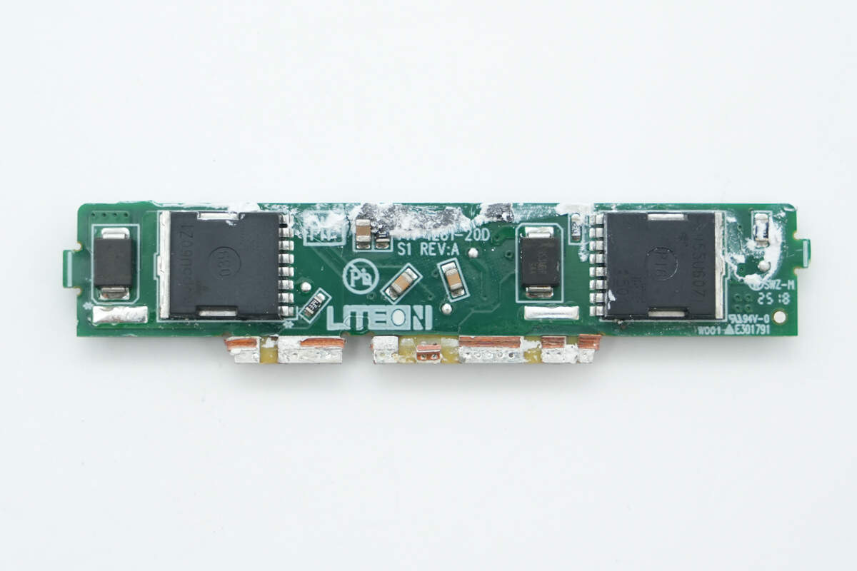
On the back side, there are two additional MOSFETs. This design uses four MOSFETs to replace the traditional bridge rectifier, driven by a controller that supports bridge rectification.
This solution effectively eliminates the majority of losses associated with conventional rectifier bridges, significantly improving the overall efficiency of the power supply. It offers advantages of high efficiency and low power loss, but requires a high-voltage driver and the use of four MOSFETs, which increases cost. This also reflects Dell’s commitment to quality in this power supply, demonstrating a willingness to invest in premium components to ensure product reliability.
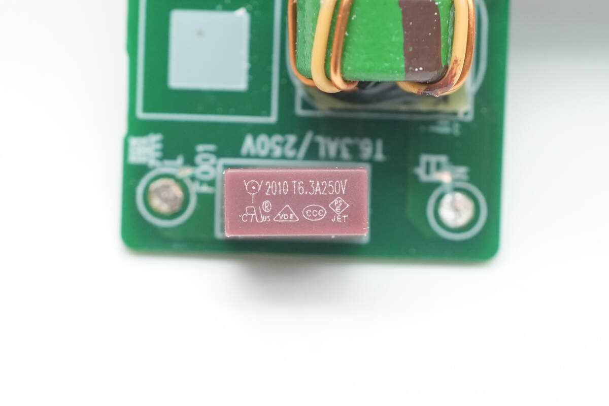
The time-delay fuse is from WalterFuse, with a rating of 6.3A 250V.
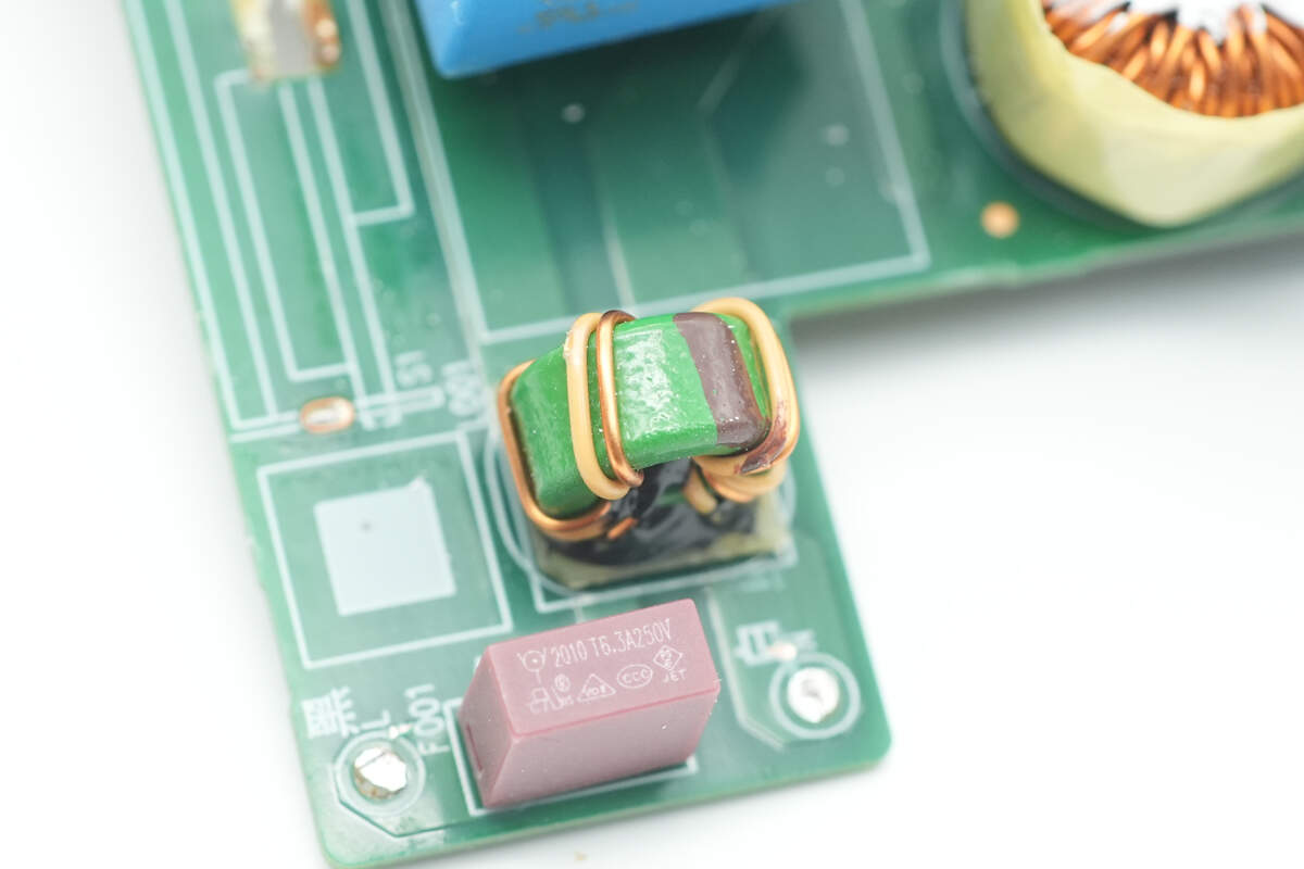
The common mode choke is dual-wound and used to filter out EMI interference.
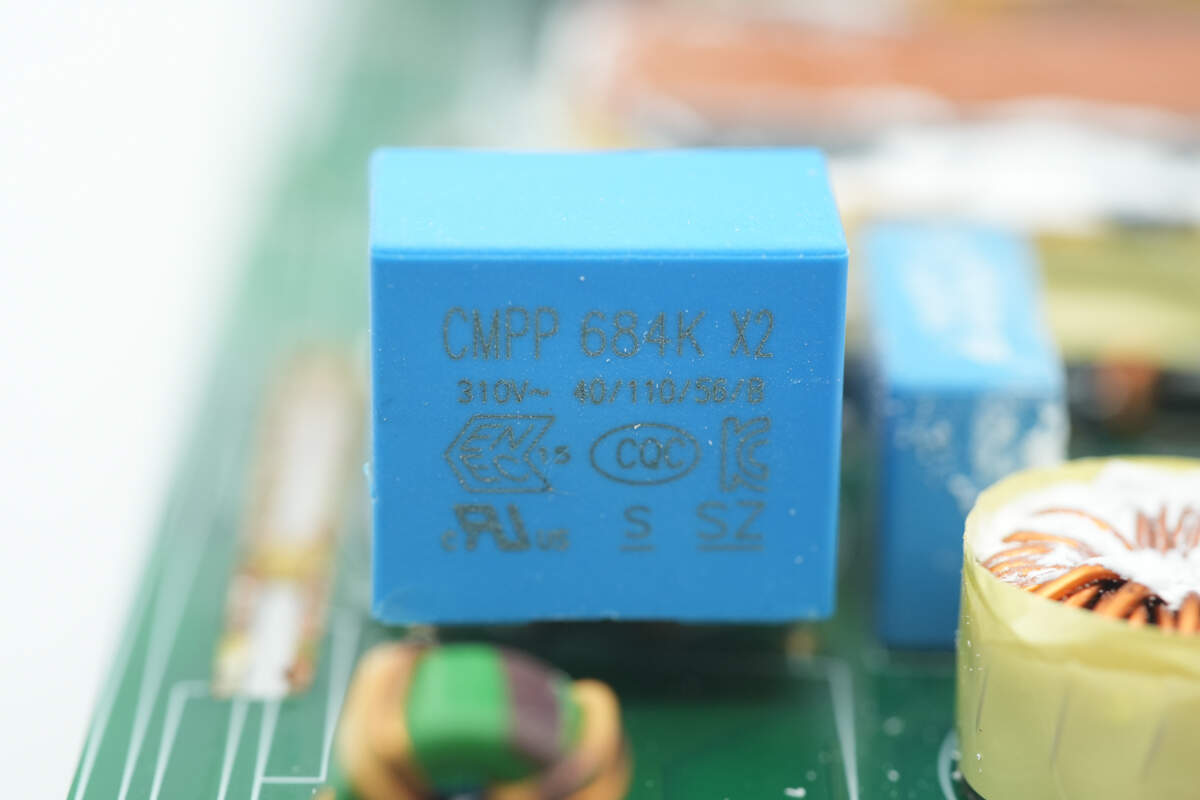
The safety X2 capacitor has a specification of 0.68μF.

Close-up of the secondary common mode choke.

The active bridge rectifier controller is from NXP, model TEA2209T. It features a built-in high-voltage driver, eliminating the need for an external driver. It can automatically switch the conduction of diagonal MOSFETs based on the polarity of the AC input voltage, achieving ultra-low-loss active rectification. The controller is housed in an SO16 package.
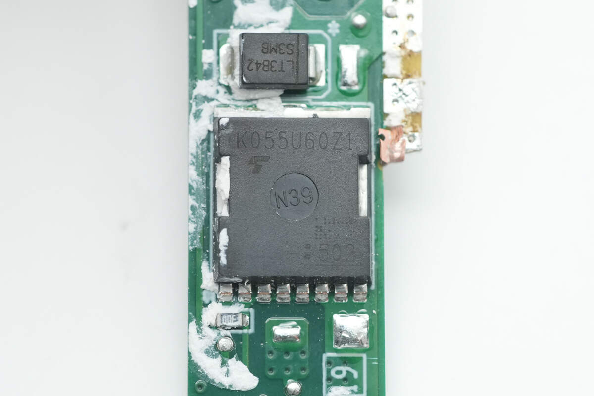
The four MOSFETs are from Toshiba, model TK055U60Z1. They are NMOS devices with a 600V voltage rating, an on-resistance of 0.046Ω, and come in a TOLL package.

Close-up of the second MOSFET.

Close-up of the third MOSFET.
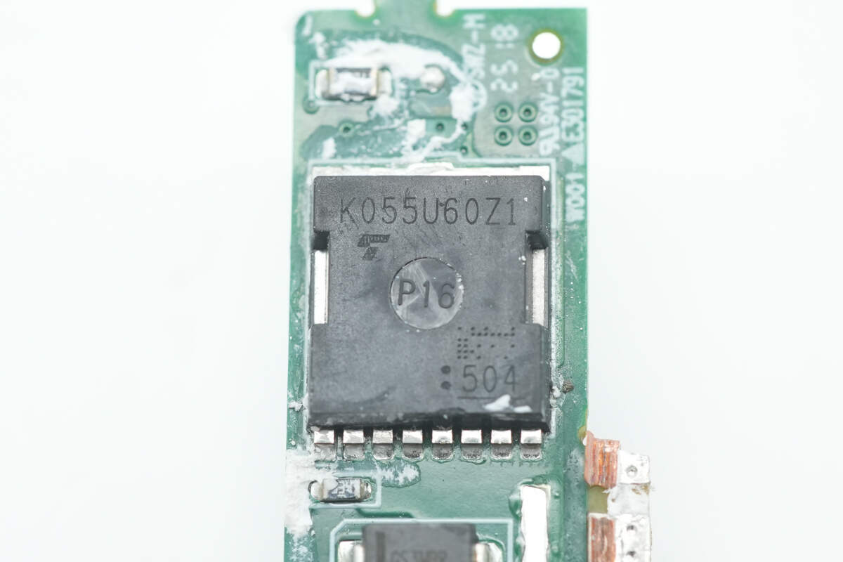
Close-up of the fourth MOSFET.

The main PCB is also equipped with an MB30KH bridge rectifier.

The film capacitor is specified as 1μF 450V.
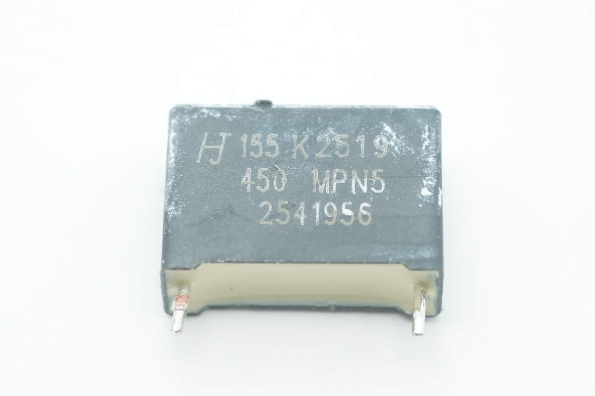
Another film capacitor is rated at 1.5μF 450V.

The filter inductor is wrapped with insulating tape.
The other side of the PCBA module is soldered with the PFC boost PCB.
Remove the PFC boost PCB. The front side features NPO resonant capacitors and a MOSFET.
The reverse side is equipped with PFC MOSFETs and NPO resonant capacitors.

The master control chip is from Infineon, marked XDPS2BF11, a custom model integrating both the PFC controller and HFB controller. It is housed in a DSO-14 package.

The PFC MOSFETs are from Infineon, marked GS8530-6LR.

Close-up of the PFC boost inductor.
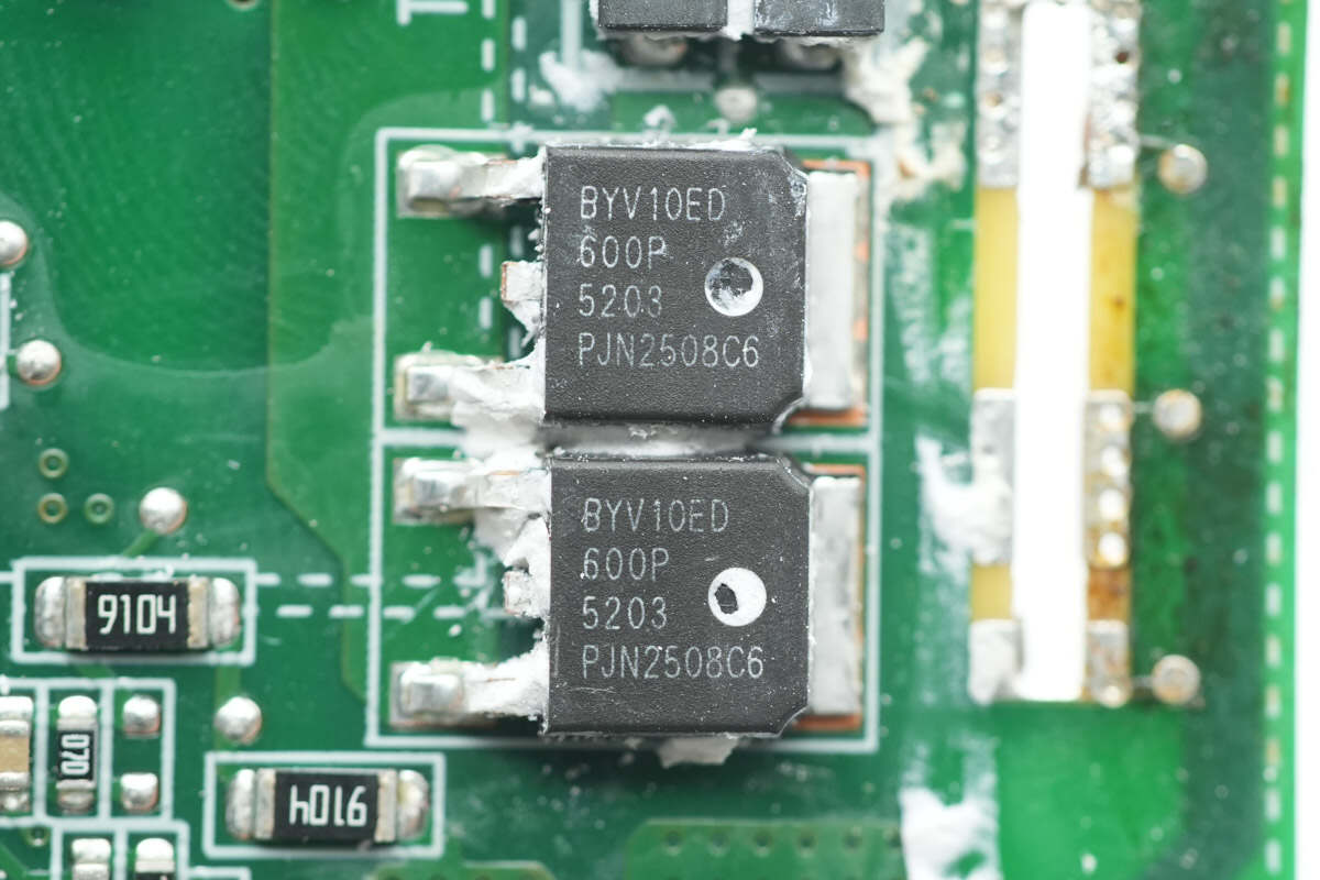
The PFC rectifiers are from RePower, model BYV10ED-600P. They are ultra-fast recovery diodes rated at 600V 10A, housed in a DPAK package.

The high-voltage filter electrolytic capacitor is from ELITE, with a specification of 180μF 450V.

The HFB half-bridge MOSFETs are also from Infineon, marked GS6530-6LR, model GS-065-030-6-LR. This is an enhancement-mode GaN FET with a voltage rating of 700V, transient voltage of 850V, on-resistance of 37mΩ, and comes in an 8×8 mm PDFN package.

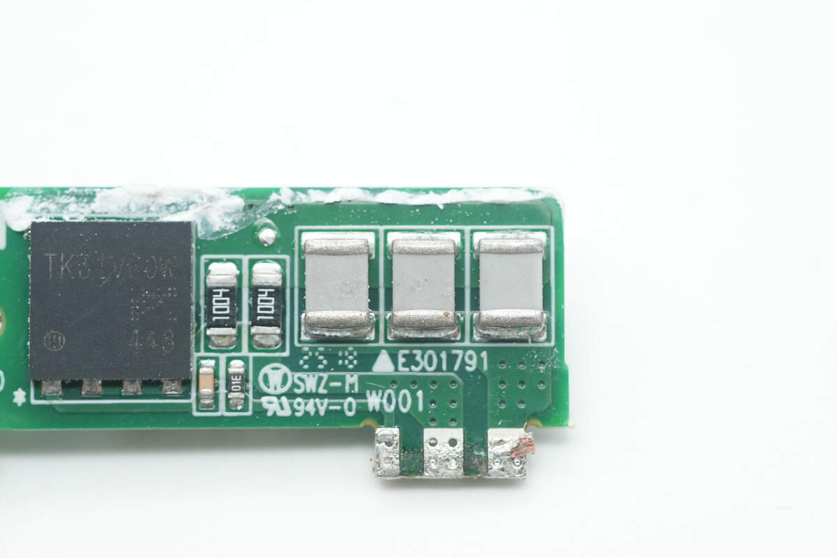
The MOSFET used for resonant capacitors switching is from Toshiba, model TK31V60W. It is an NMOS device with a 600V voltage rating, 78mΩ on-resistance, and comes in an 8×8 mm DFN package.
Close-up of the NPO resonant capacitors.
Close-up of another set of NPO resonant capacitors.
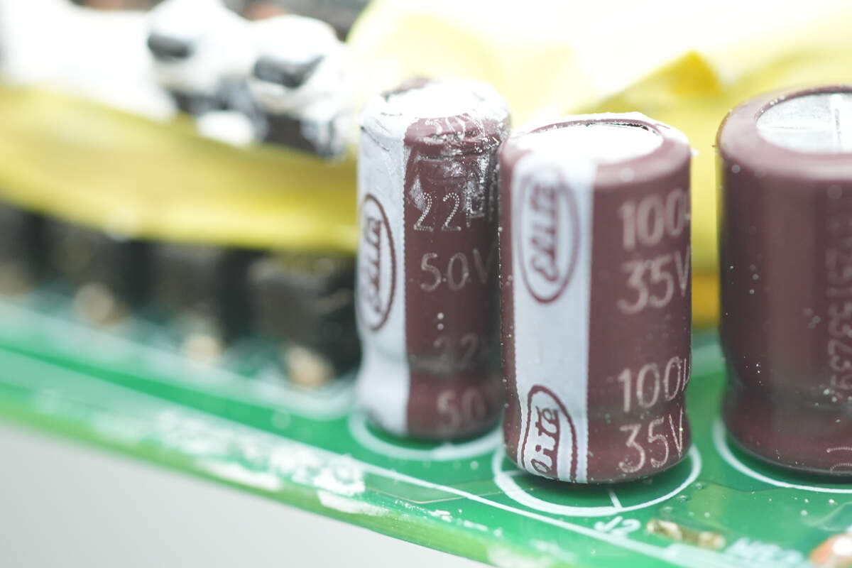
The capacitor supplying power to the master control chip is also from ELITE, with a specification of 22μF 50V.
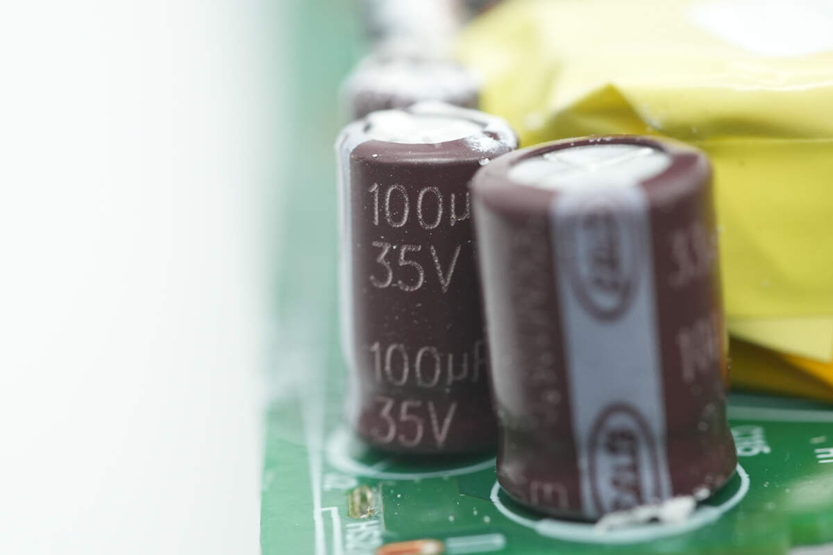
The second capacitor is rated at 100μF 35V.
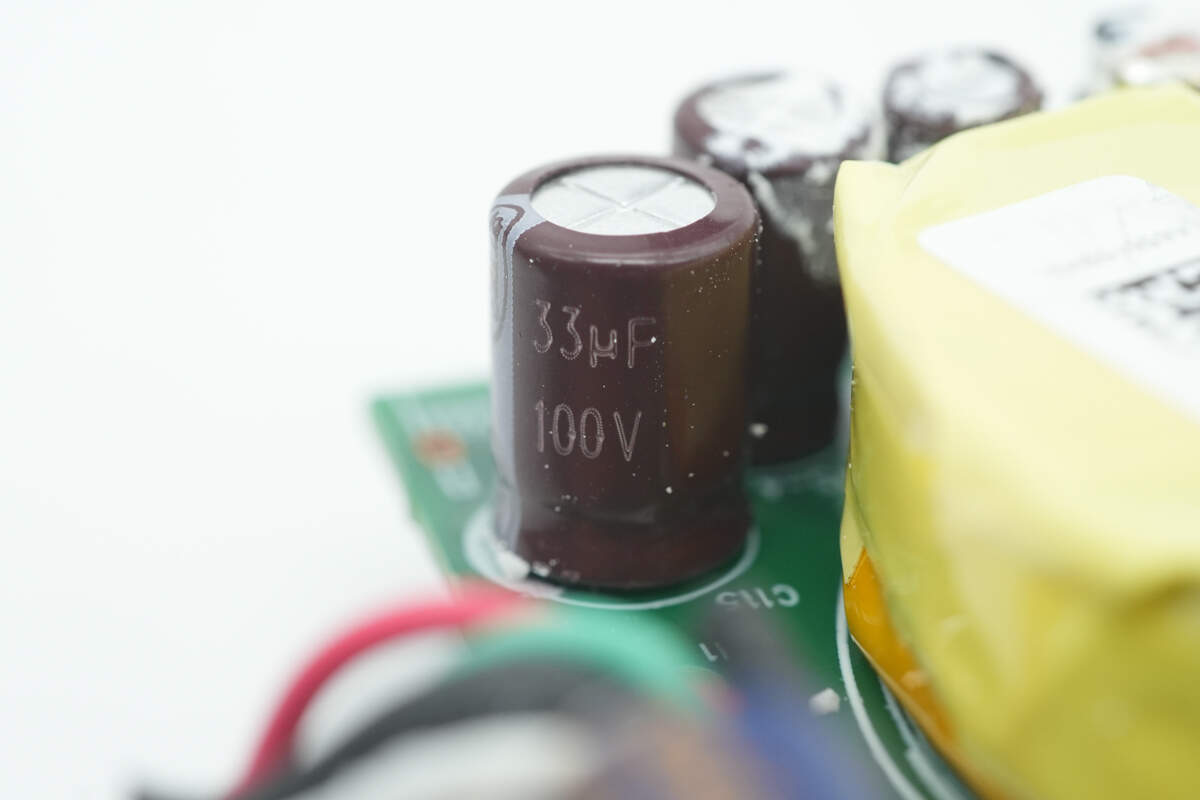
The third capacitor is specified as 33μF 100V.
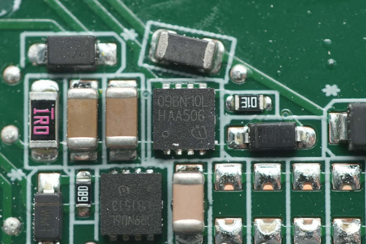
The power supply MOSFET is from Infineon, marked 096N10L, model BSZ096N10LS5. It is an NMOS device with a 100V voltage rating, 9.6mΩ on-resistance, and comes in a TSDSON-8 FL package.

The other power supply MOSFET is from Infineon, marked 099N06L, model BSZ099N06LS5. It is an NMOS device with a 60V voltage rating, 9.9mΩ on-resistance, and comes in a TSDSON-8 FL package.

The transformer secondary winding uses Litz wire, with the magnetic core insulated by adhesive tape.

LITEON LTV-1007 optocouplers are used for feedback and protection control.
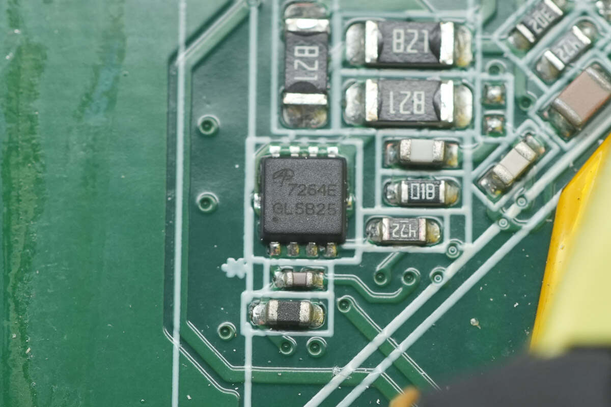
The output discharge MOSFET is from AOS, model AON7264E. It is an NMOS device with a 60V voltage rating, 7.7mΩ on-resistance, and comes in a DFN 3×3 EP package.

The synchronous rectifier controller is marked with ICDGS.

The synchronous rectifiers are from APEC, model AP15NA9R3CXT. They are NMOS devices with a 150V voltage rating, 9.3mΩ on-resistance, and come in a PMP5×6X package.

Two solid capacitors for output filtering are from CapXon, both rated at 470μF 63V.

Close-up of the filter inductor.
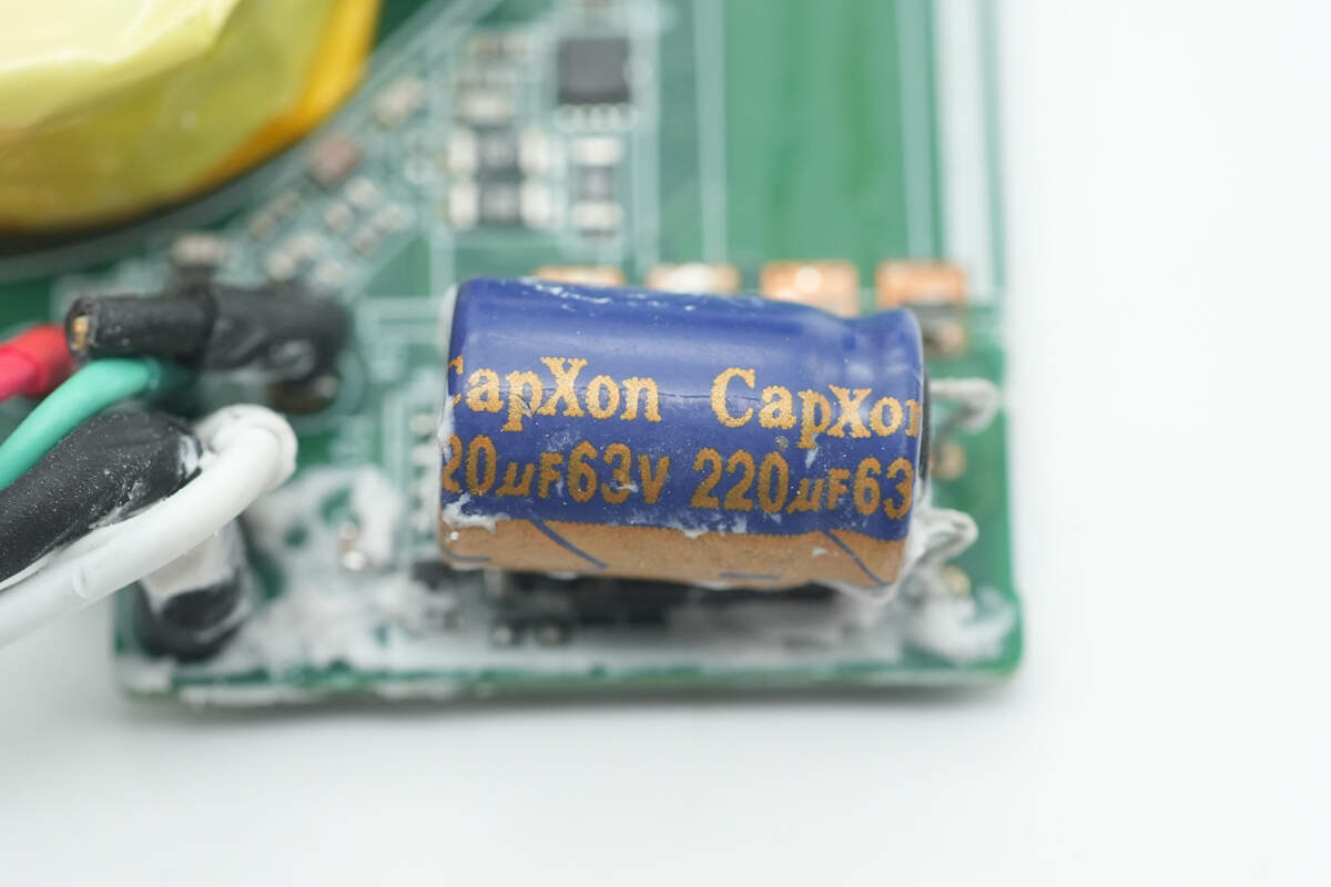
There is an electrolytic capacitor for output filtering from CapXon, rated at 220μF 63V.

The MPS MP4569 is a 75V/0.3A synchronous buck converter with a wide input voltage range of 4.5–75V, making it particularly suitable for various step-down applications in automotive environments. It can deliver up to 0.3A of efficient output current. Its ultra-low shutdown current of 3.5μA makes it ideal for battery-powered scenarios.
The device reduces switching frequency under light load conditions to minimize switching losses and gate drive losses, thereby achieving high power conversion efficiency across a wide load range. During startup and short-circuit conditions, the switching frequency also automatically decreases to prevent inductor current runaway. An internal thermal shutdown feature ensures reliable and fault-tolerant operation. The chip is available in QFN-10 (3mm × 3mm) and SOIC-8 EP packages.

Close-up of the 33μH buck inductor.

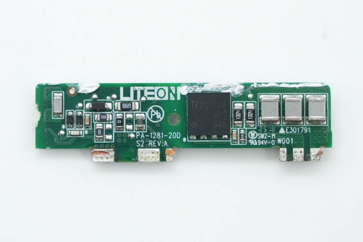
The protocol chip is from Weltrend, model WT6678F. It supports USB PD 3.1 SPR and ERP 48V standards, integrating PD PHY, USB Type-C detection, voltage and current detectors, an MCU, and drivers. It operates within a 3.3–56V voltage range and comes in a QFN16 package.
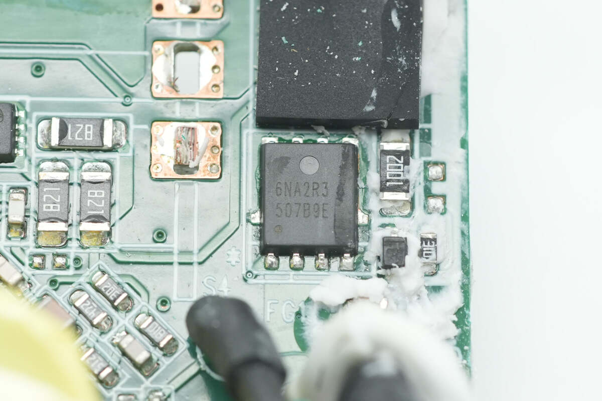
The output VBUS MOSFET is from XSEMI, model XP6NA2R3MT. It is an NMOS device with a 60V voltage rating, 2.3mΩ on-resistance, and comes in a PMP5×6 package.

Well, those are all components of the Dell 280W USB-C GaN AC Adapter.
Summary of ChargerLAB

Here is the component list of the Dell 280W USB-C GaN AC Adapter for your convenience.
The power cable features a detachable design. It supports a wide input voltage range of 100–240V and complies with safety certifications applicable in the vast majority of countries worldwide. Designed based on a GaN solution, it supports up to 280W output and is compatible with the PD3.1 fast charging standard, delivering up to 48V 5A fast charging.
After taking it apart, we found that it utilizes the NXP TEA2209T paired with Toshiba TK055U60Z1 MOSFETs for active rectification. It features a custom Infineon XDPS2BF11 master control chip and also incorporates two GaN devices from Infineon. The output is controlled by a Weltrend WT6678F protocol chip. Filter capacitors are sourced from both ELITE and CapXon. Components are reinforced with adhesive, and the module is covered by a heatsink to aid heat dissipation, demonstrating meticulous workmanship.
Related Articles:
1. Teardown of Bel Fuse 3000W GaN Server Power Supply (TET3000-12-069RA)
2. Teardown of Gospower 1300W DC Server Power Supply (G1232-1300WND)
3. Teardown of Xiaomi 17 Pro Retro Handheld Console Case (25099TC43C)