Introduction
Several weeks ago, we posted a teardown video of the CUKTECH No.30 power bank, you can click here to check it. While this product received some mockery from Linus Tech Tips in one of their recent videos due to its peculiar brand name, we can assure you that aside from the slightly odd name, CUKTECH's products are unquestionably top-notch in terms of performance and craftsmanship.
That's why today, we got another power bank from CUKTECH, the No.20 power bank. Let's go ahead and take apart this power bank to see what it looks like inside.
Product Appearance
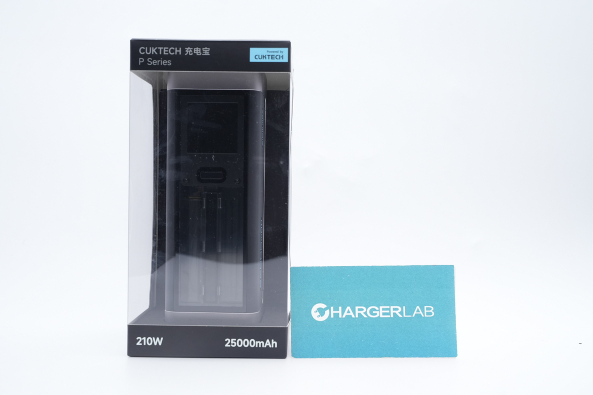
The transparent packaging is unique, and it belongs to the P series. Model is P23.
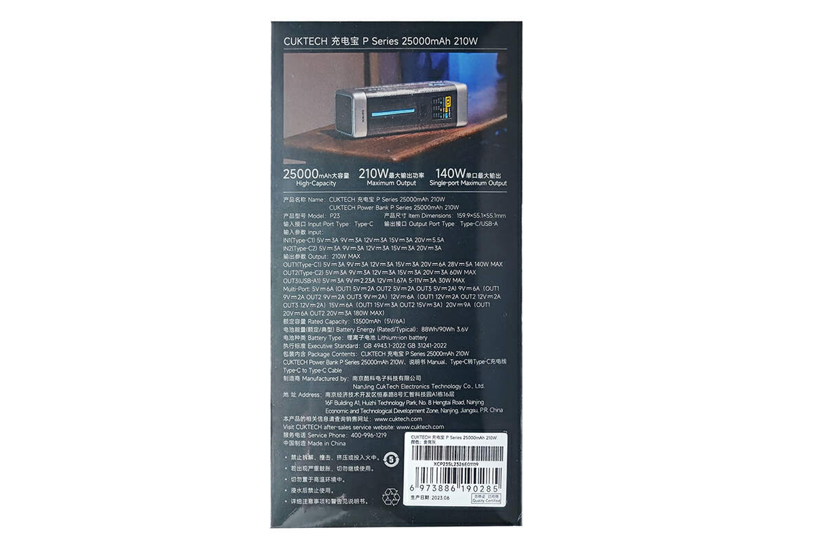
Flip to the back. All specs info are on the back.
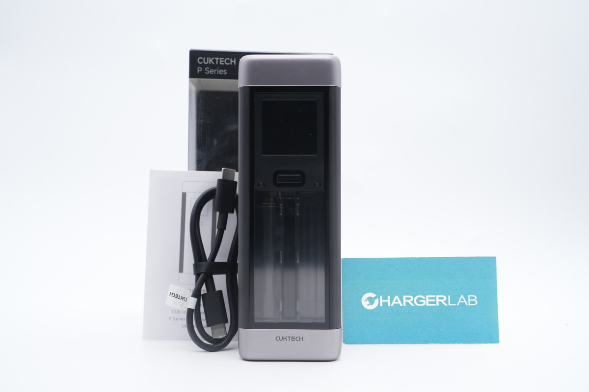
Take it out from the top of the box. Except for the power bank, it also comes with a dual USB-C cable and a user manual.
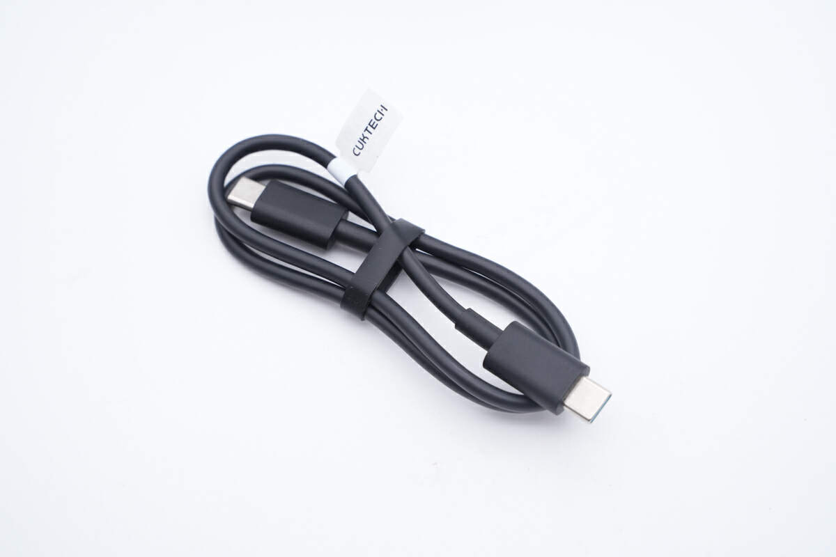
The cable is actually a short one for easy carry.
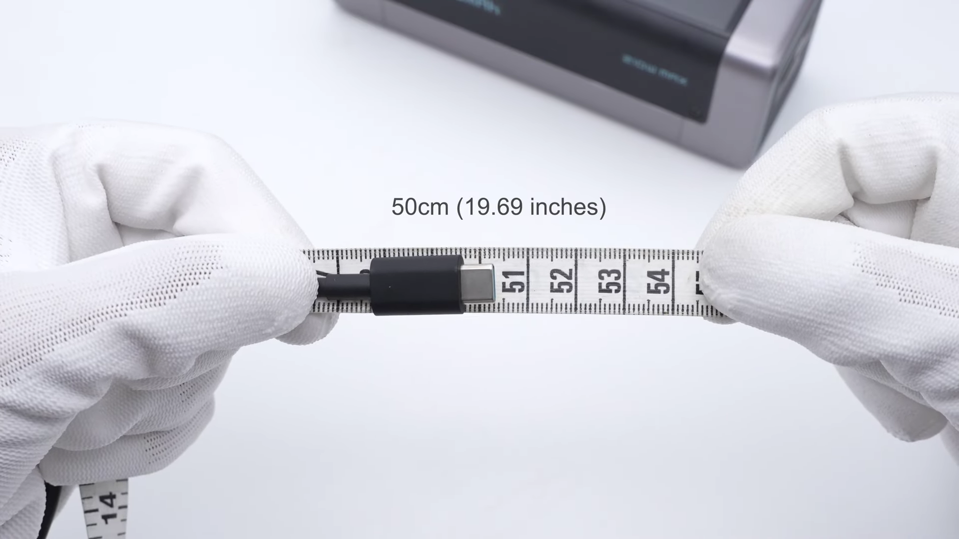
The length of this cable is about 50cm (19.69 inches).
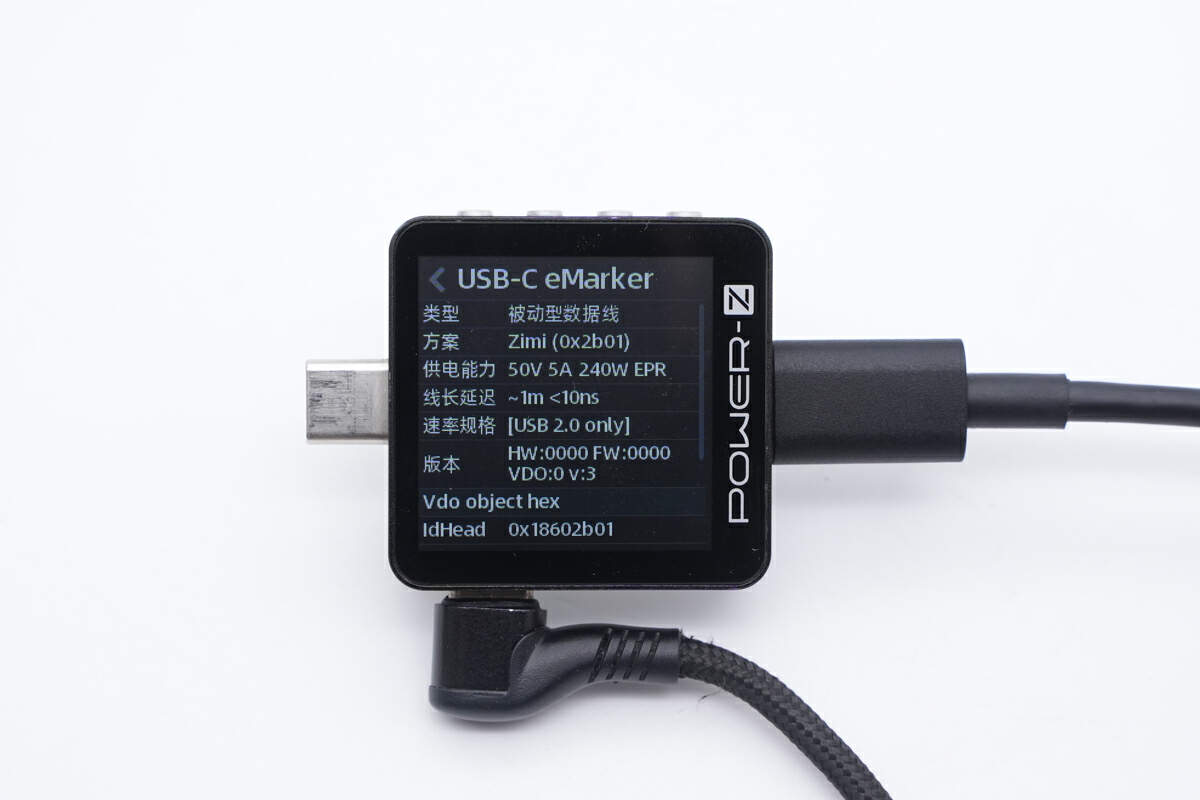
The ChargerLAB POWER-Z KM003C shows it supports up to 240W and USB 2.0.
Moving on to the power bank, it looks like the Anker 140W PD3.1 power bank we took apart before.
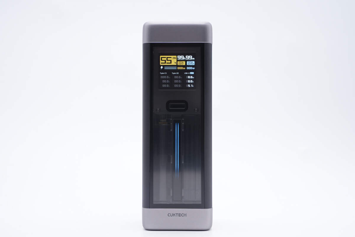
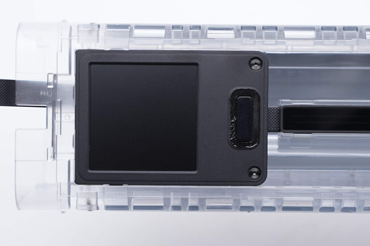
There's a display on the front, with a power button below it.
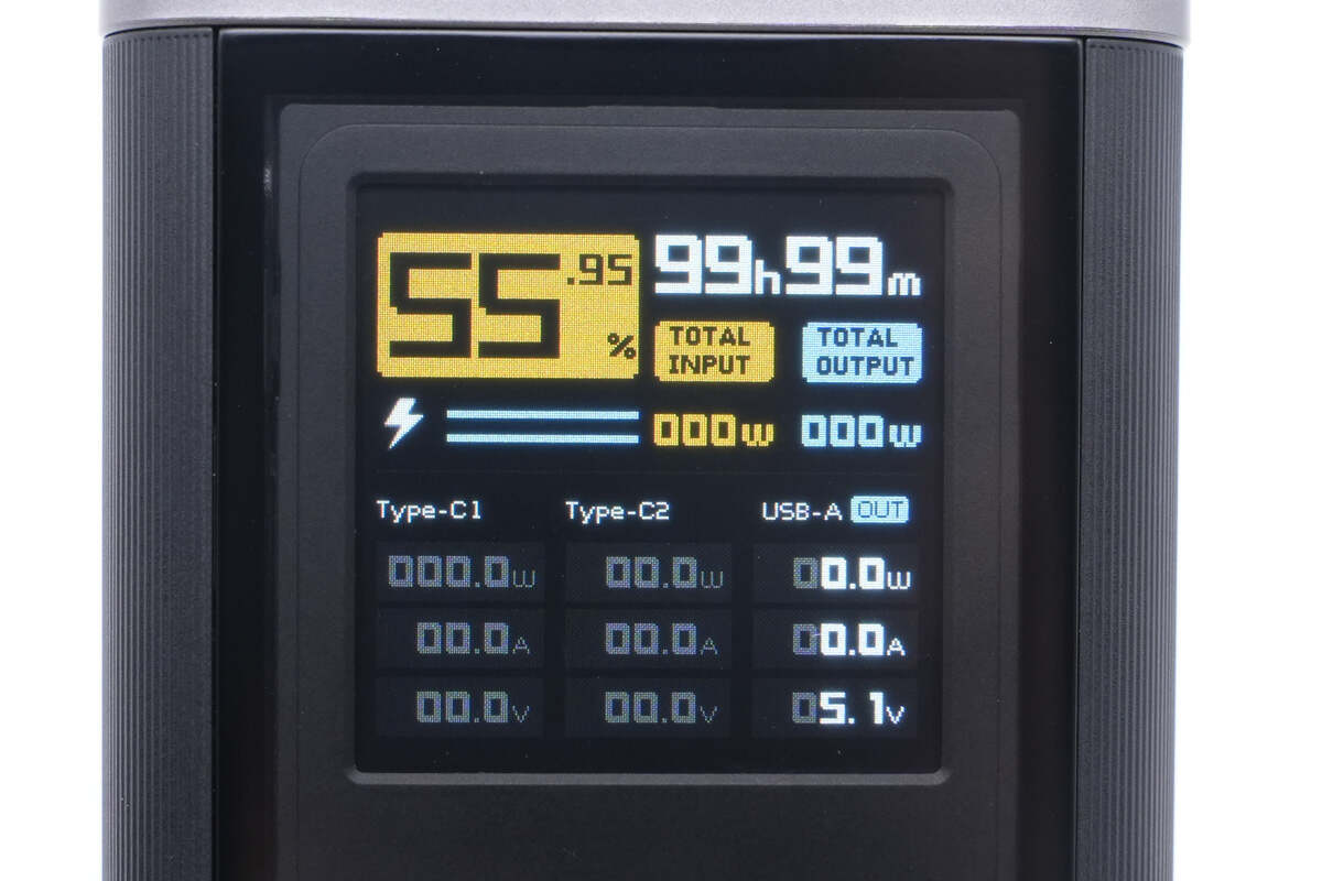
The display has a vivid UI with rich functionality, capable of real-time showing remaining battery capacity, voltage, current, power for each port, as well as the total input/output power. A must-have for tech-savvy gamers.
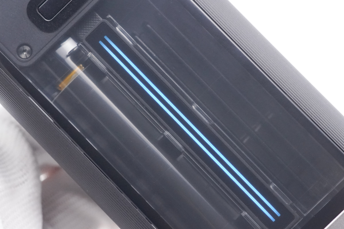
And there is also a pulse blue LED strip.
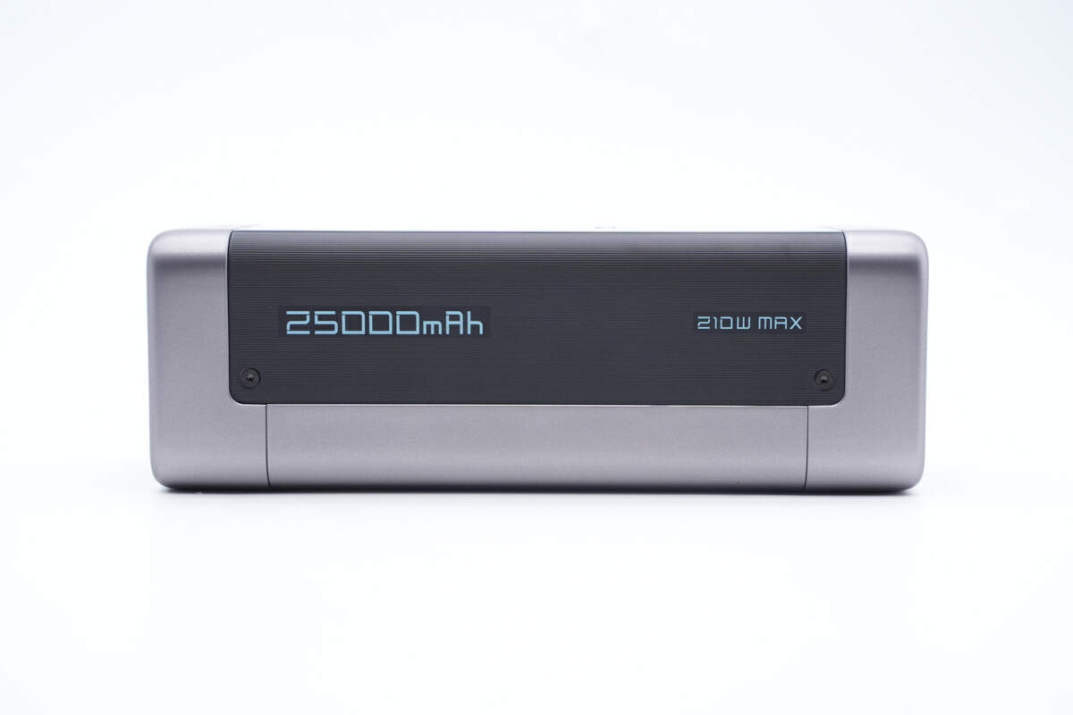
The shell's edges have a smooth and rounded transition, and the black strip on the side can make the power bank more stable.
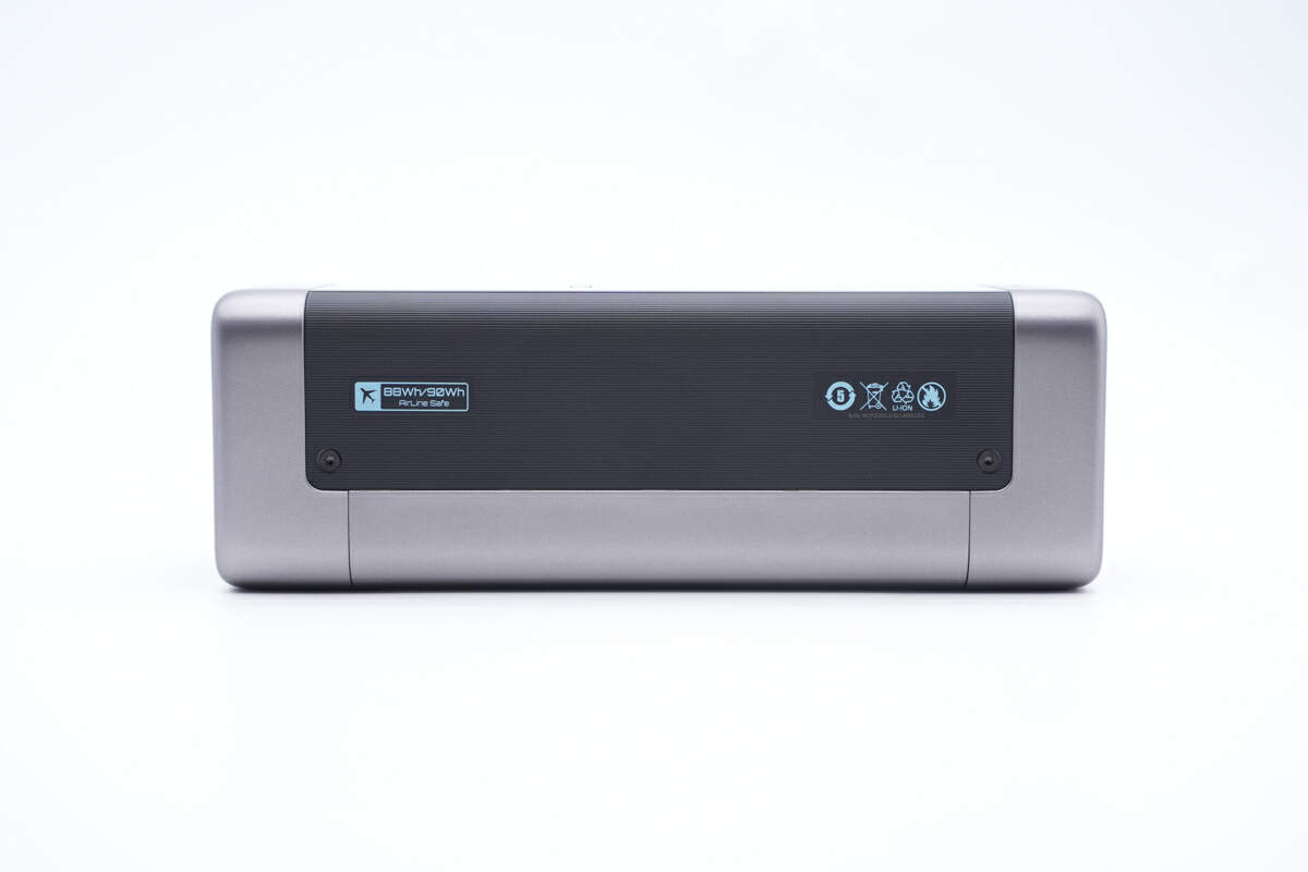
Since the maximum energy does not exceed 100 Wh, you can put it into your backpack or handbag and board the plane.
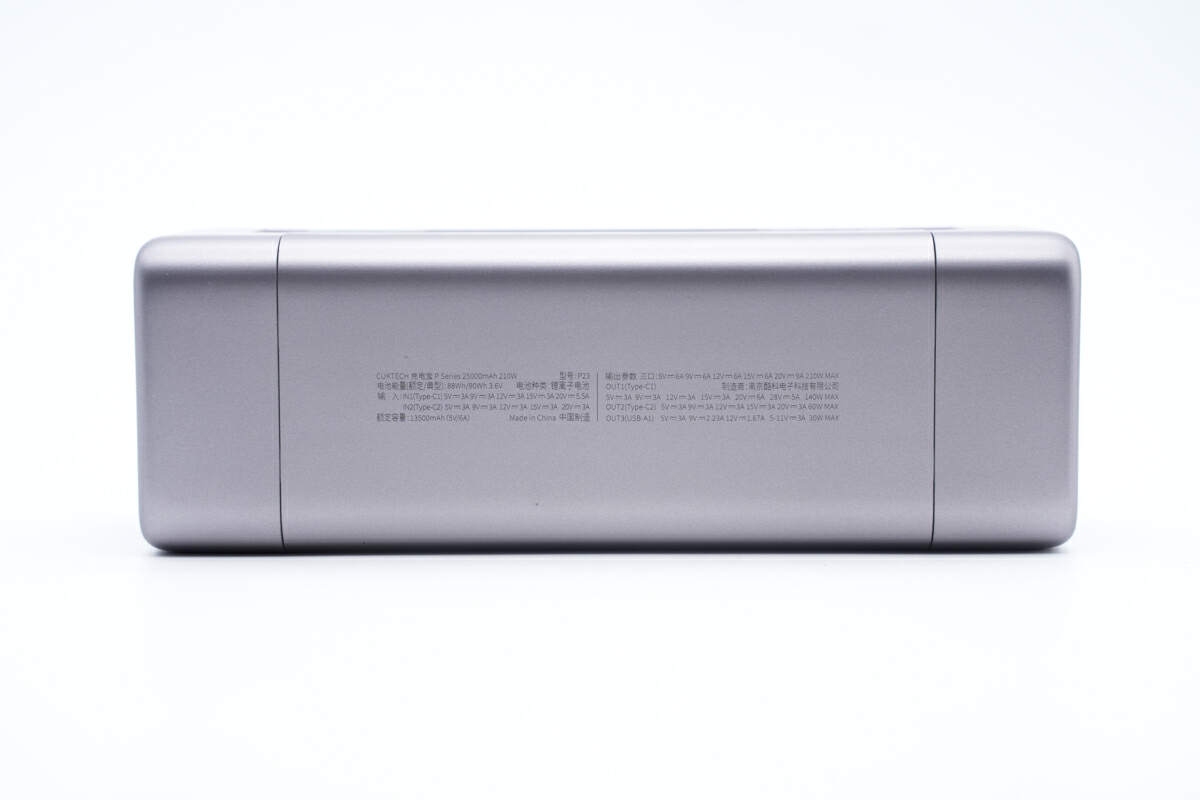
Specs info are on this side.
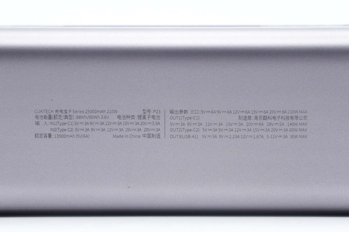
The model is P23. The rated energy is 88Wh at 3.6V, and the rated capacity is 13500mAh (5V6A). It's worth noting that the advertised output of 210W can only be achieved when all three ports are used simultaneously. The maximum power output for a single port is 140W for USB-C1 (28V5A), and for USB-C2 and USB-A, it is 60W and 30W, respectively.
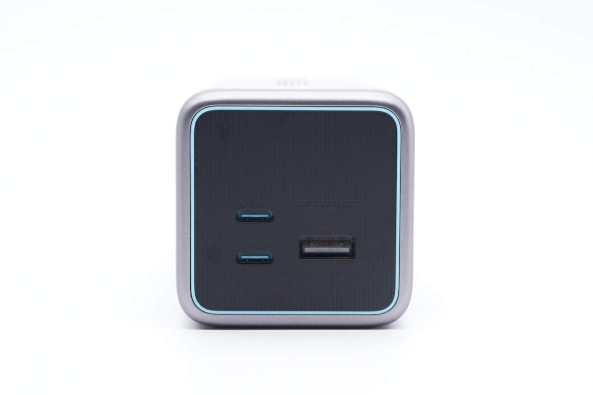
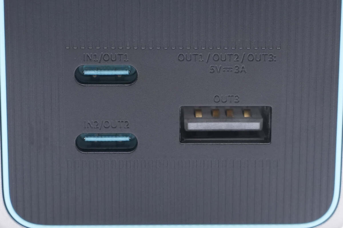
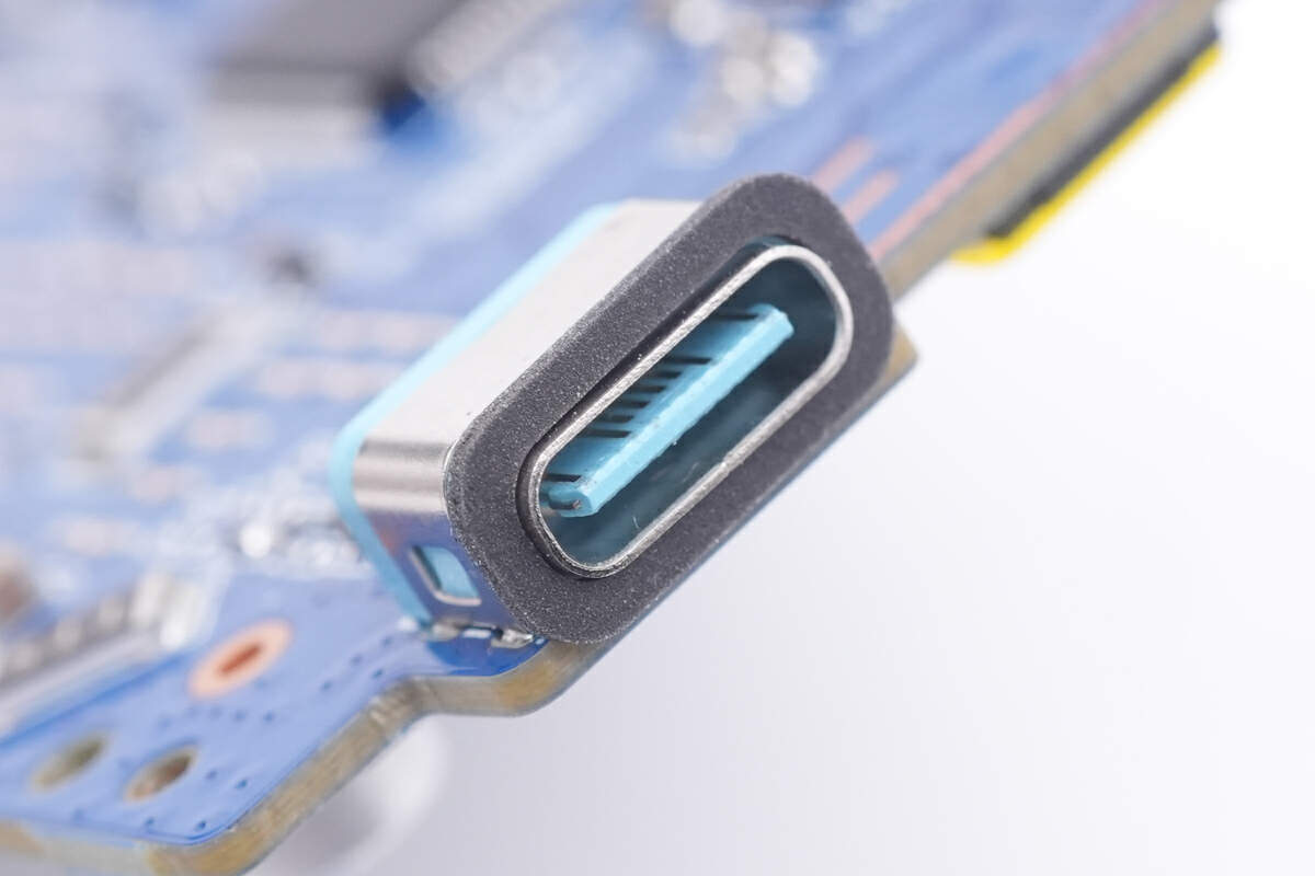
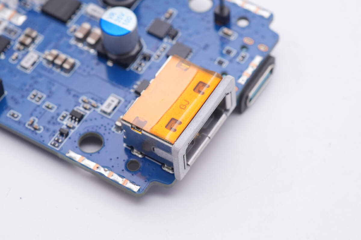
Here are the two USB-C and a USB-A ports on the output panel.
It simply tells you some basic info, but fear not, because we also got three detailed power distribution guides for you.
Here is the single-port situation.
Dual-port.
And three-port.
The black strip also exists on the top and bottom.
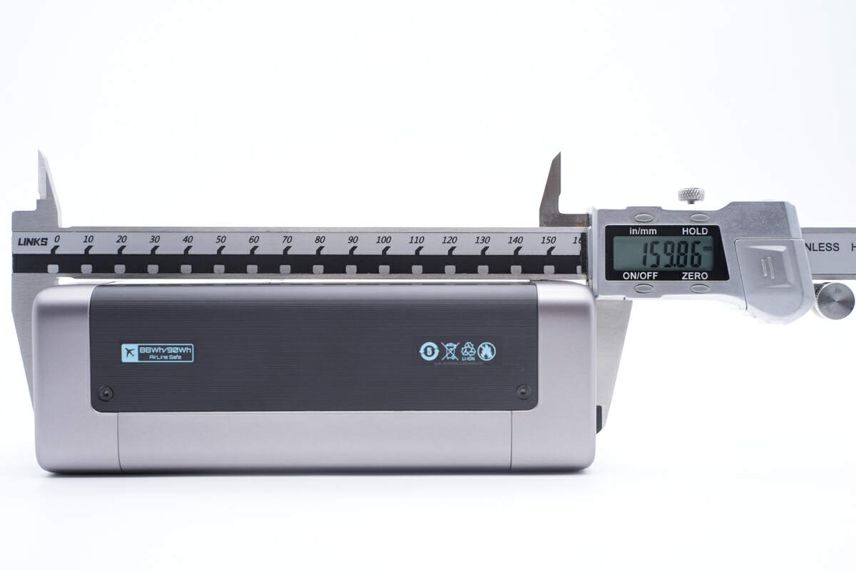
The length of this power bank is about 160mm (6.30 inches).
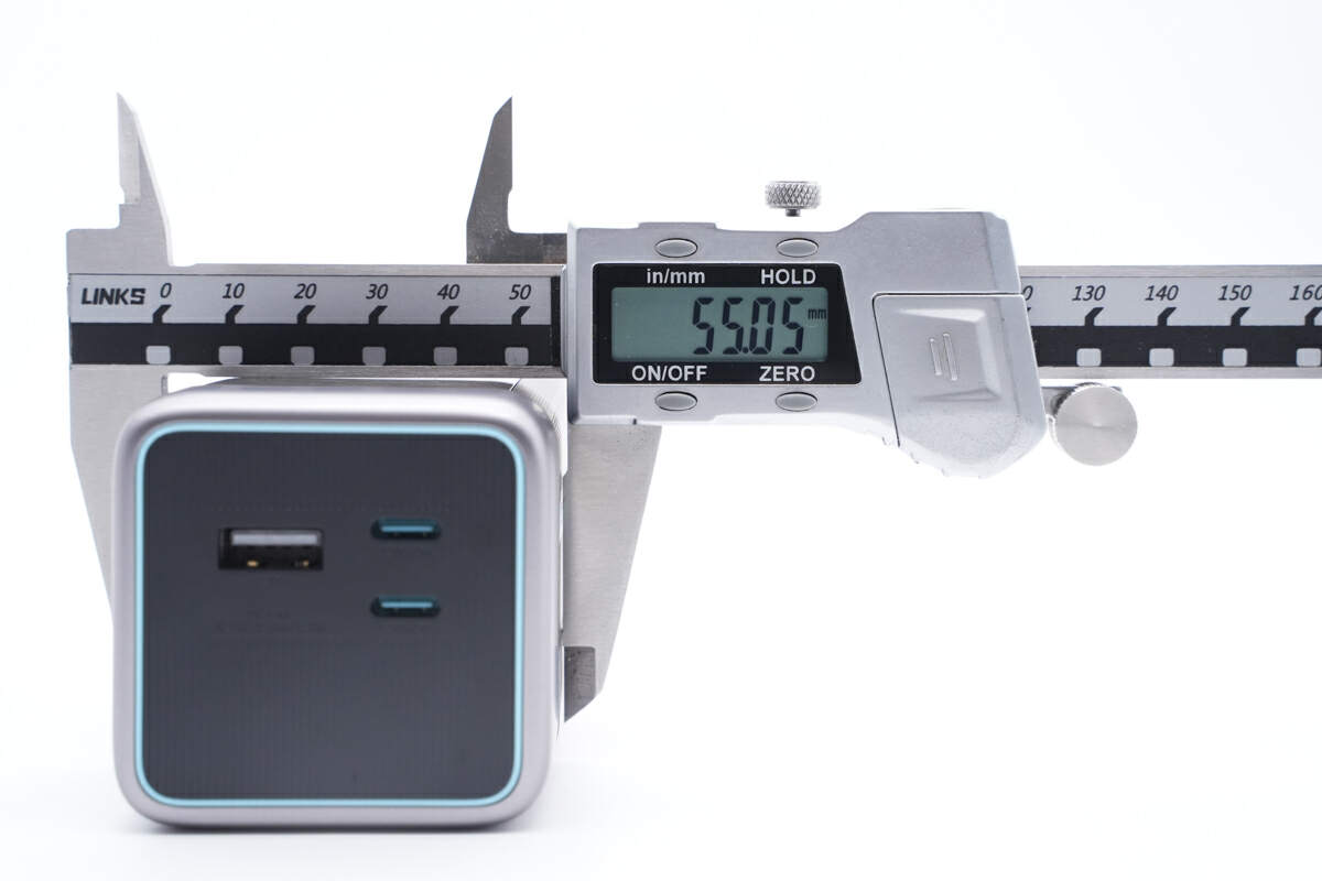
The width is about 55mm (2.17 inches).
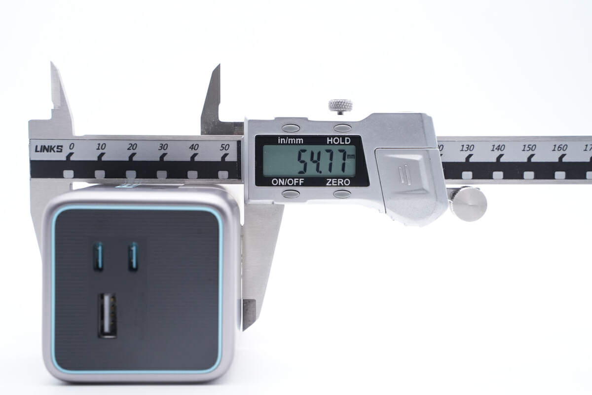
And the height is also about 55mm (2.17 inches).
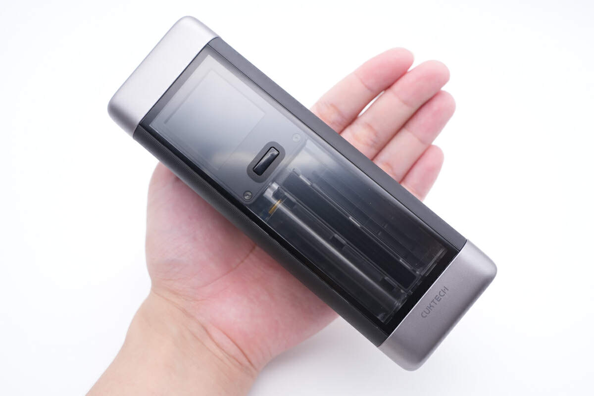
This is how it looks like on my hand.
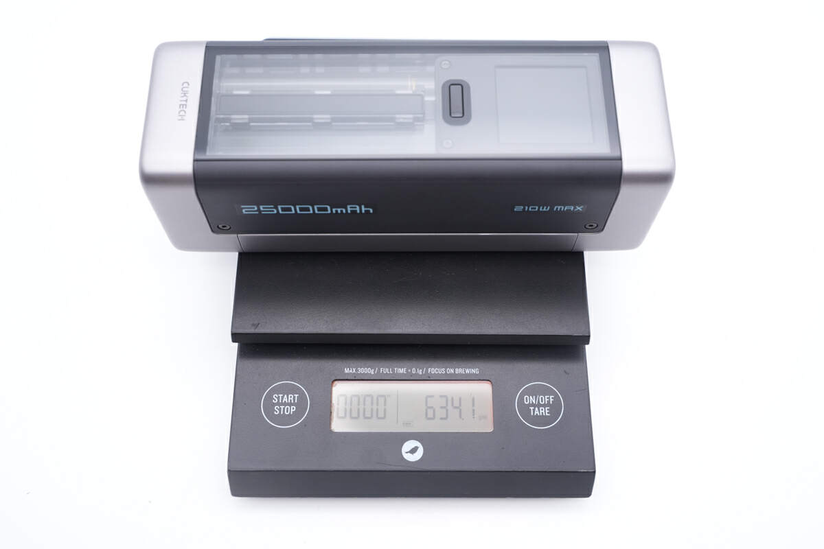
And the weight is about 634g (22.36 oz).
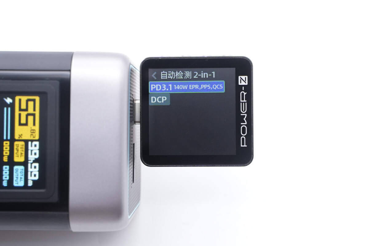
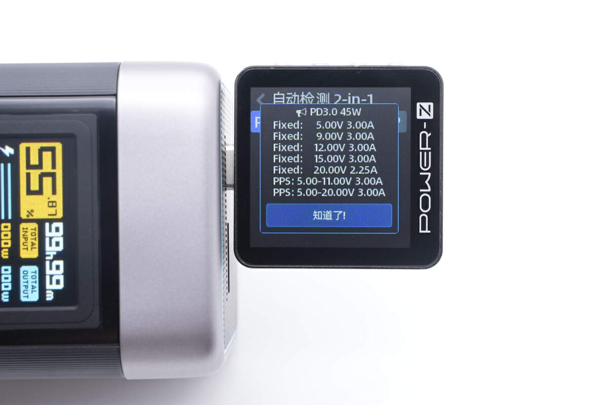
The ChargerLAB POWER-Z KM003C shows the USB-C1 supports PD3.1, PPS, QC5, DCP protocols.
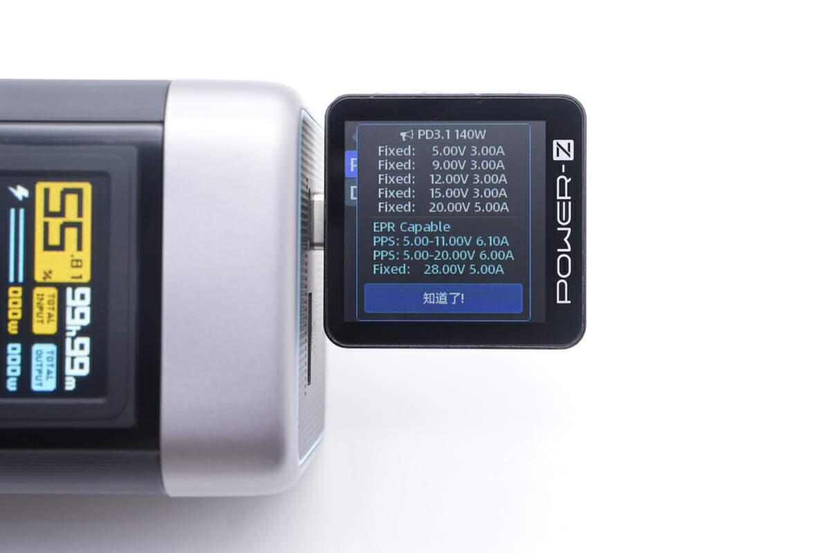
It also has six fixed PDOs of 5V/9V/12V/15V3A, 20V/28V5A and two sets of PPS.
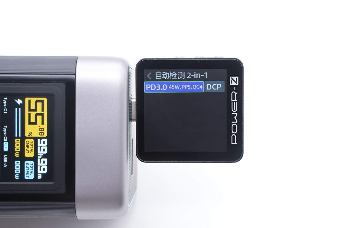
As for the USB-C2, it only supports PD3.0, PPS, QC4, DCP protocols.
It also has five fixed PDOs of 5V/9V/12V/15V3A, 20V2.25A and two sets of PPS.
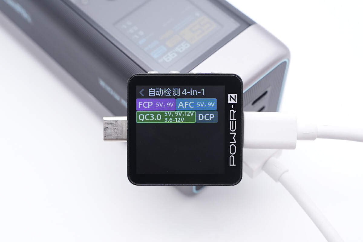
Finally, the USB-A supports FCP, AFC, QC3.0, DCP protocols.
Teardown
Now that we have completed our unboxing and testing of this power bank, it's time to take apart the device and examine its internal components and structure.
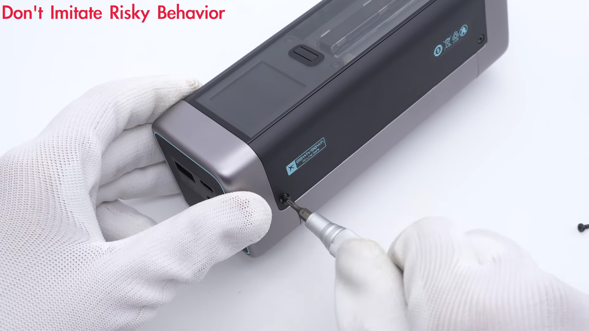
The first step is to remove two screws on the side.
And remove the top and bottom covers.

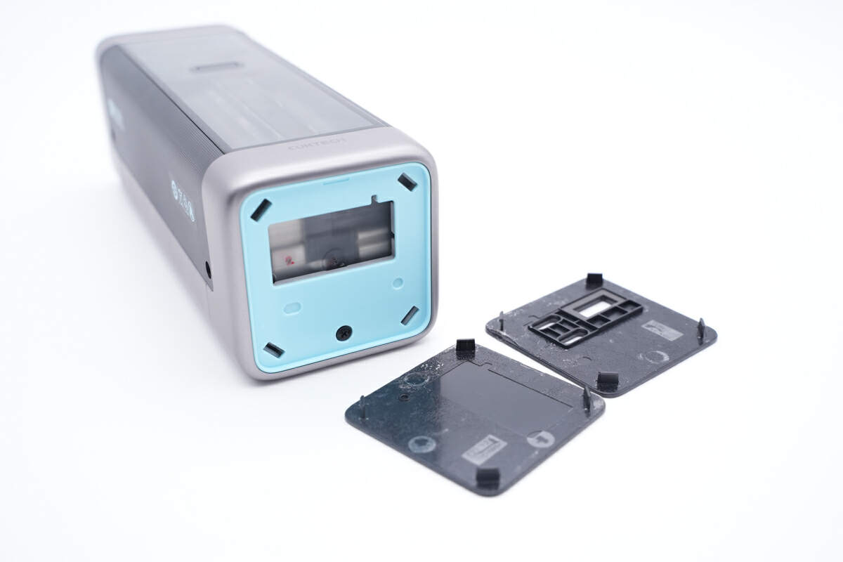
Underneath the cover, there is another blue plastic panel, also secured with screws.
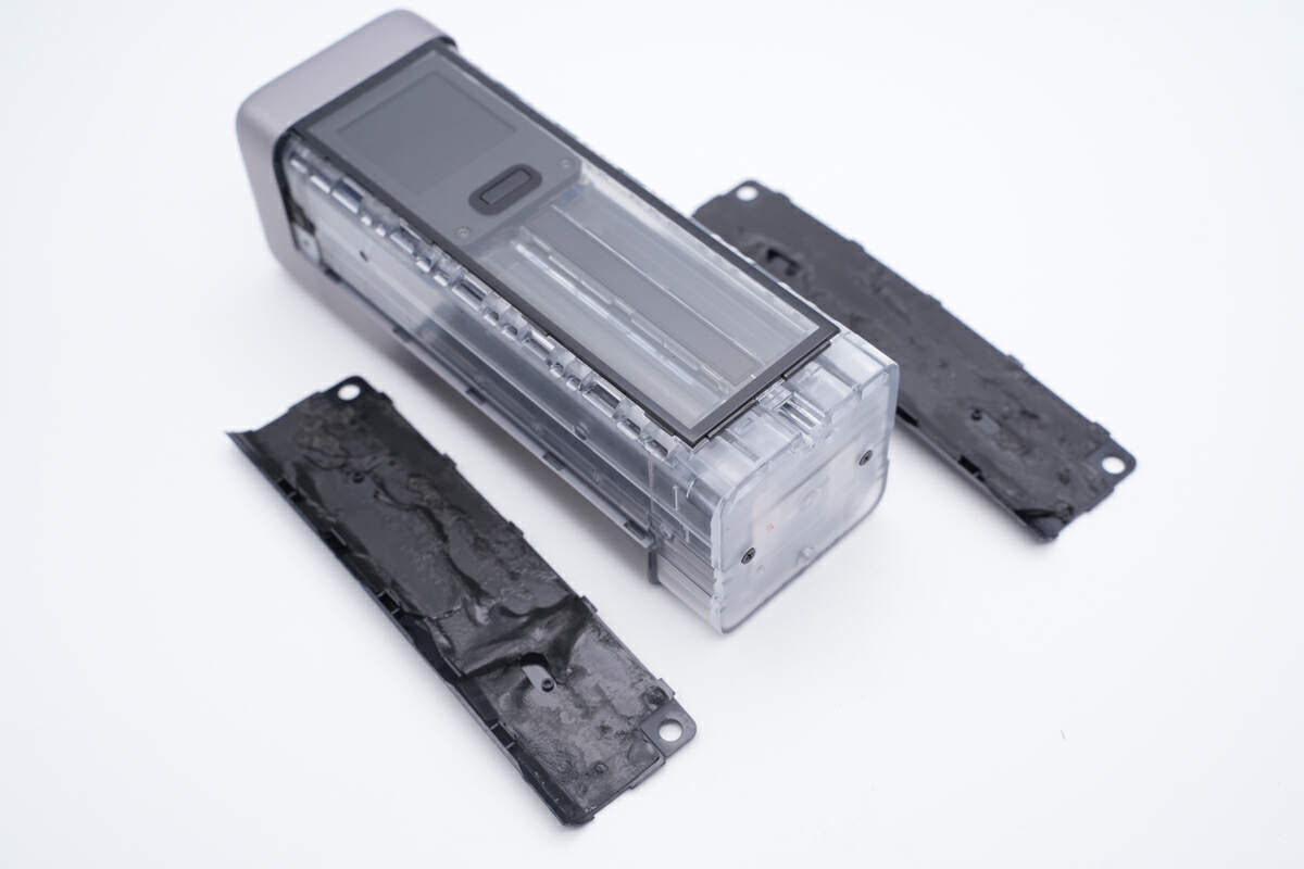
The black strips on both sides are fixed with double-sided adhesive and can be easily peeled off.
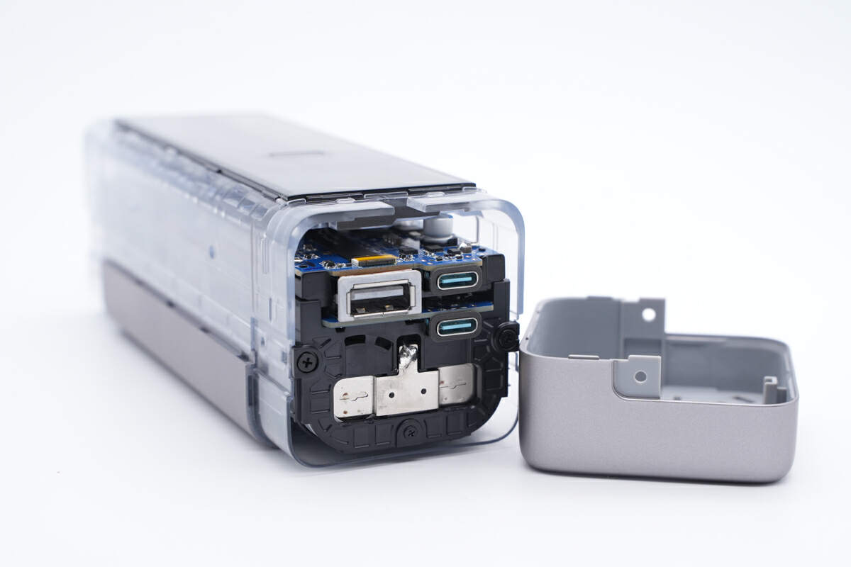
Unscrew the fixing screws on both sides and remove the gray cover of the output panel.
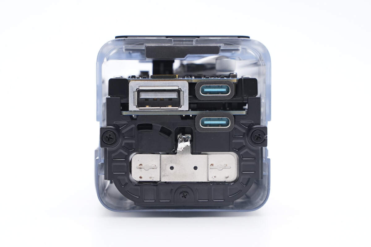
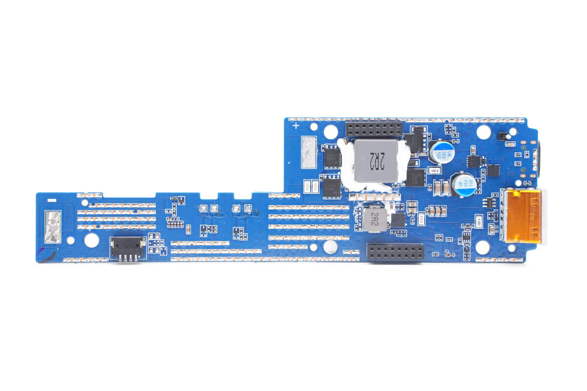
Now, we can see the internal PCB.
Continue to remove the remaining screws, the entire module can be easily taken out.
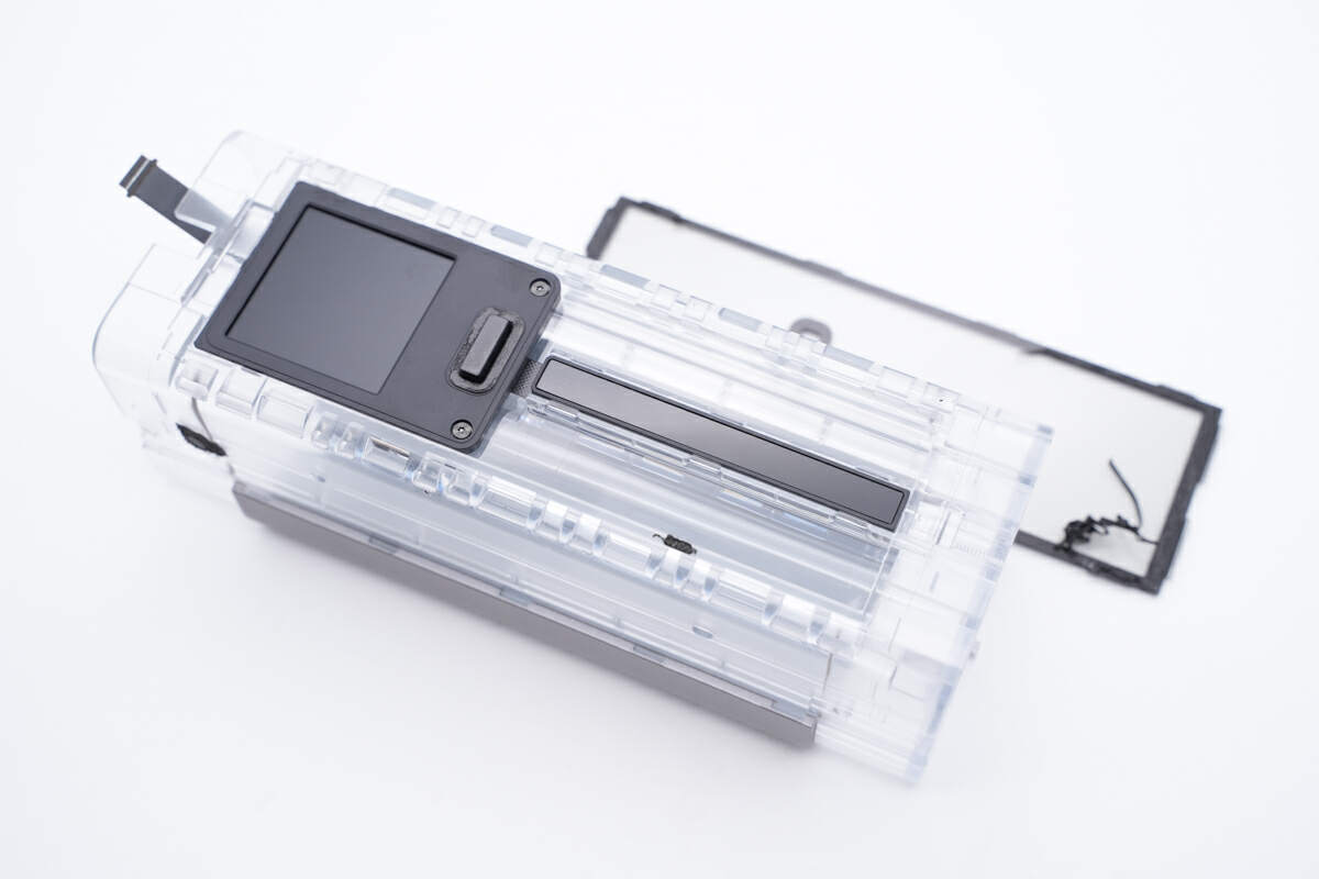
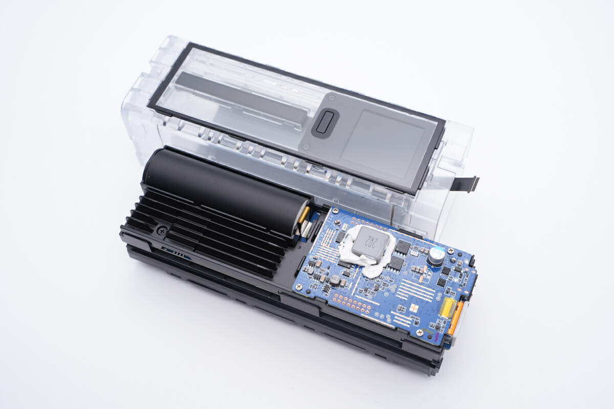
Remove the transparent panel.
The display is secured with a black plastic cover.
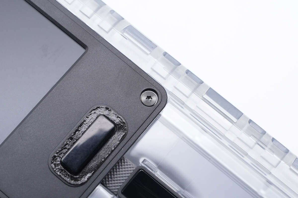
The cover is also fixed with screws.
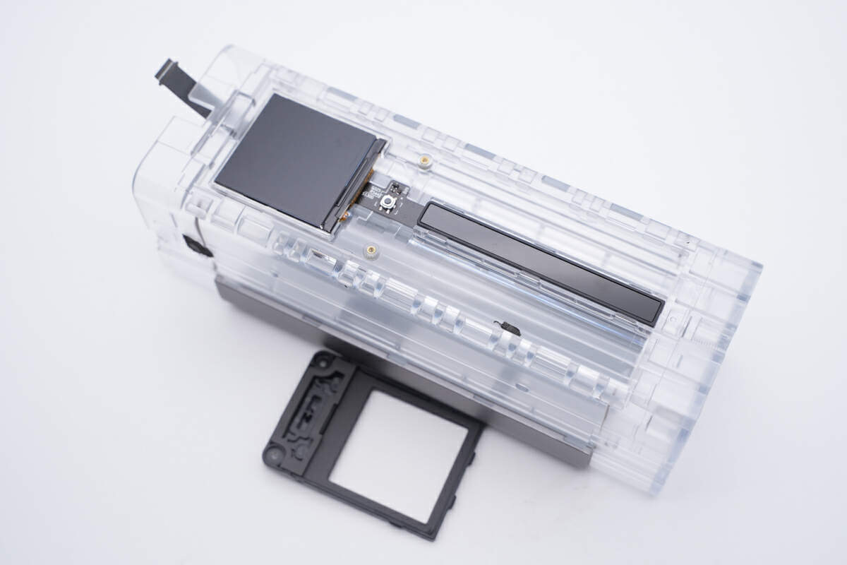
Take it out.
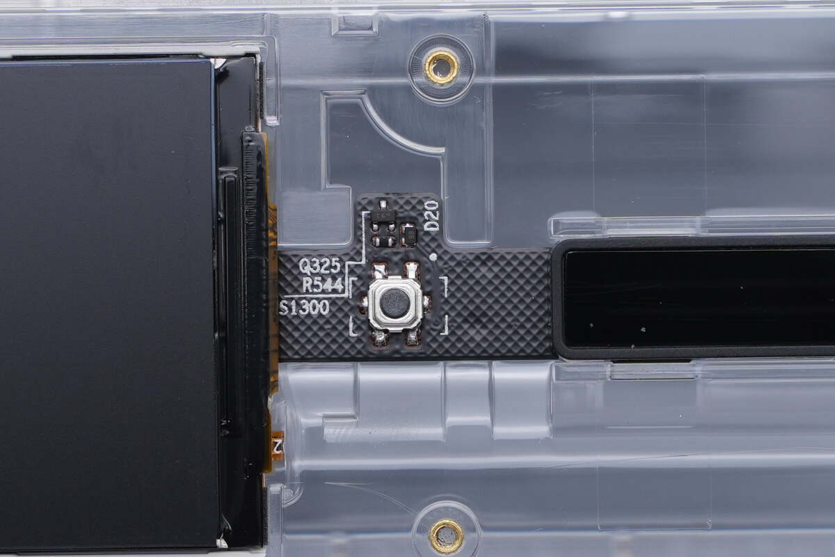
The micro switch is soldered on the flat cable.
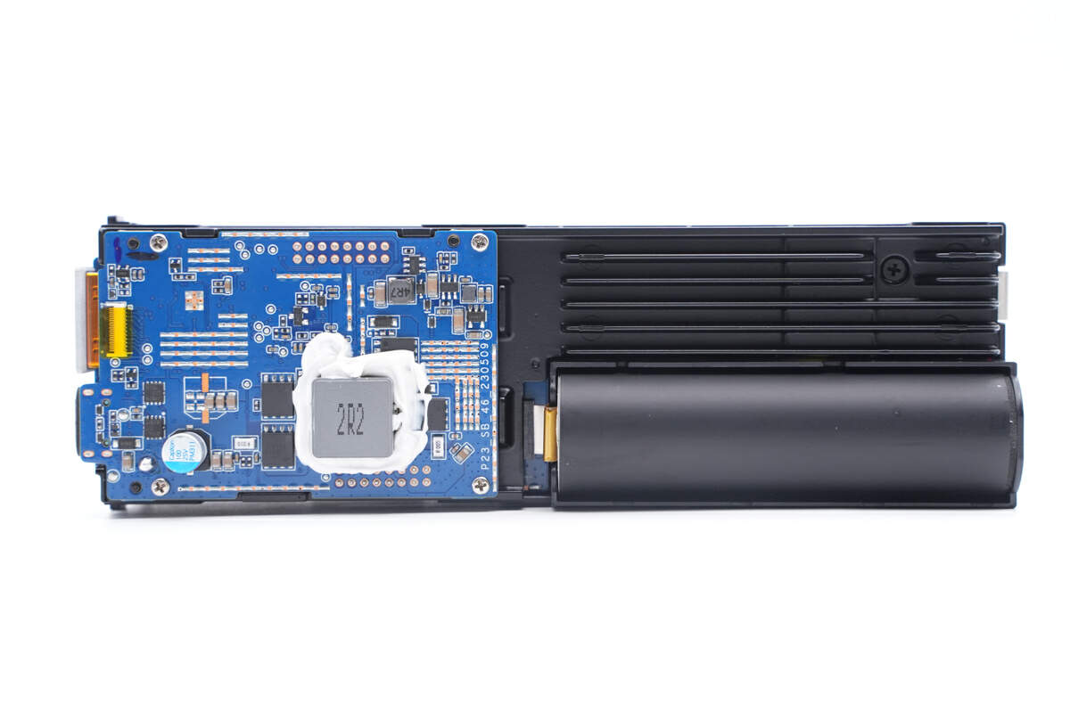
The first PCB is on the upper layer.
It is secured with four screws.
Unscrew all the screws, and you can remove the upper layer of PCB, revealing a large black aluminum alloy plate used for heat dissipation.
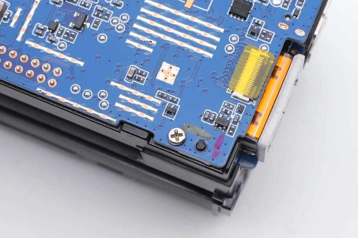
The backside of the PCB is attached with two gray thermal pads.
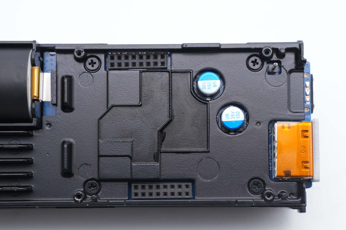
The aluminum alloy plate has two openings designed for placing filter capacitors.
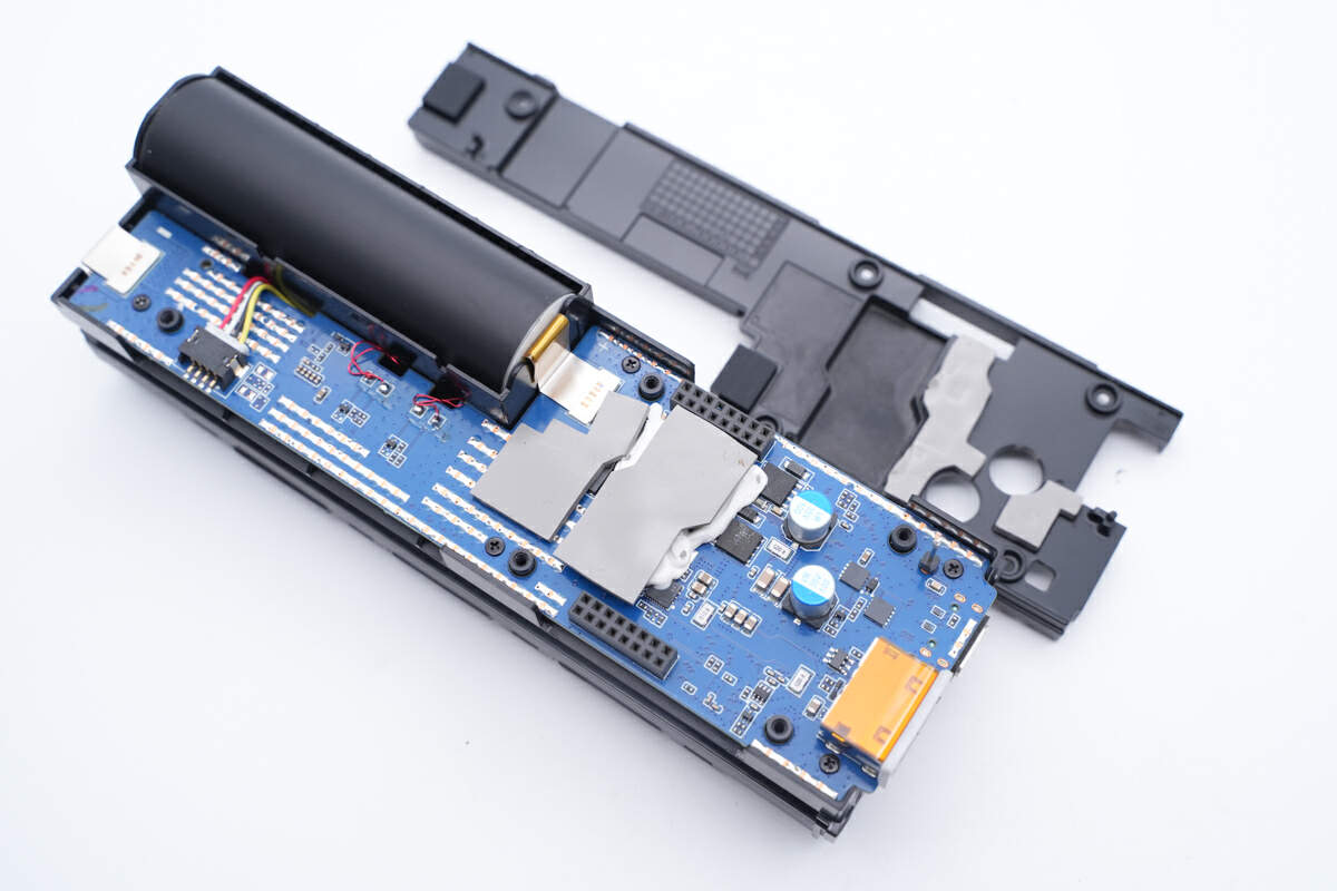
The lower PCB is also attached with two gray thermal pads.
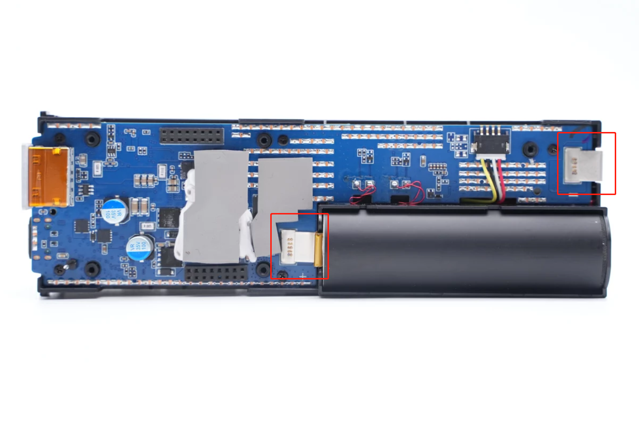
It is larger than the first one, a battery cell is in the lower right corner. Two nickel strips are connected to PCB by solder joints.
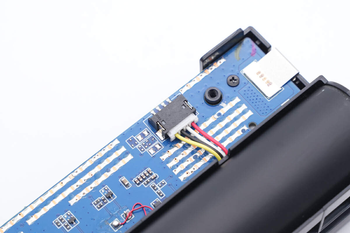
Here is the connector of the acquisition wires of battery cells.
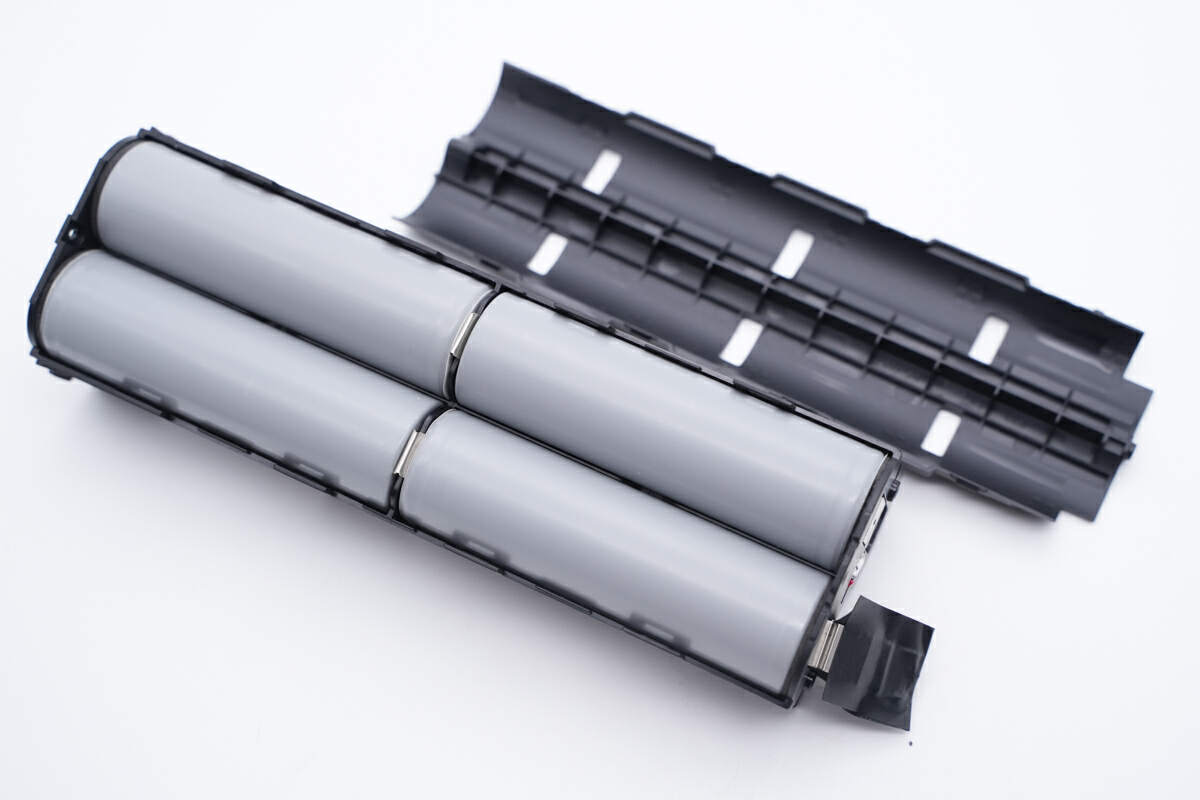
The other four battery cells are under the main PCB.
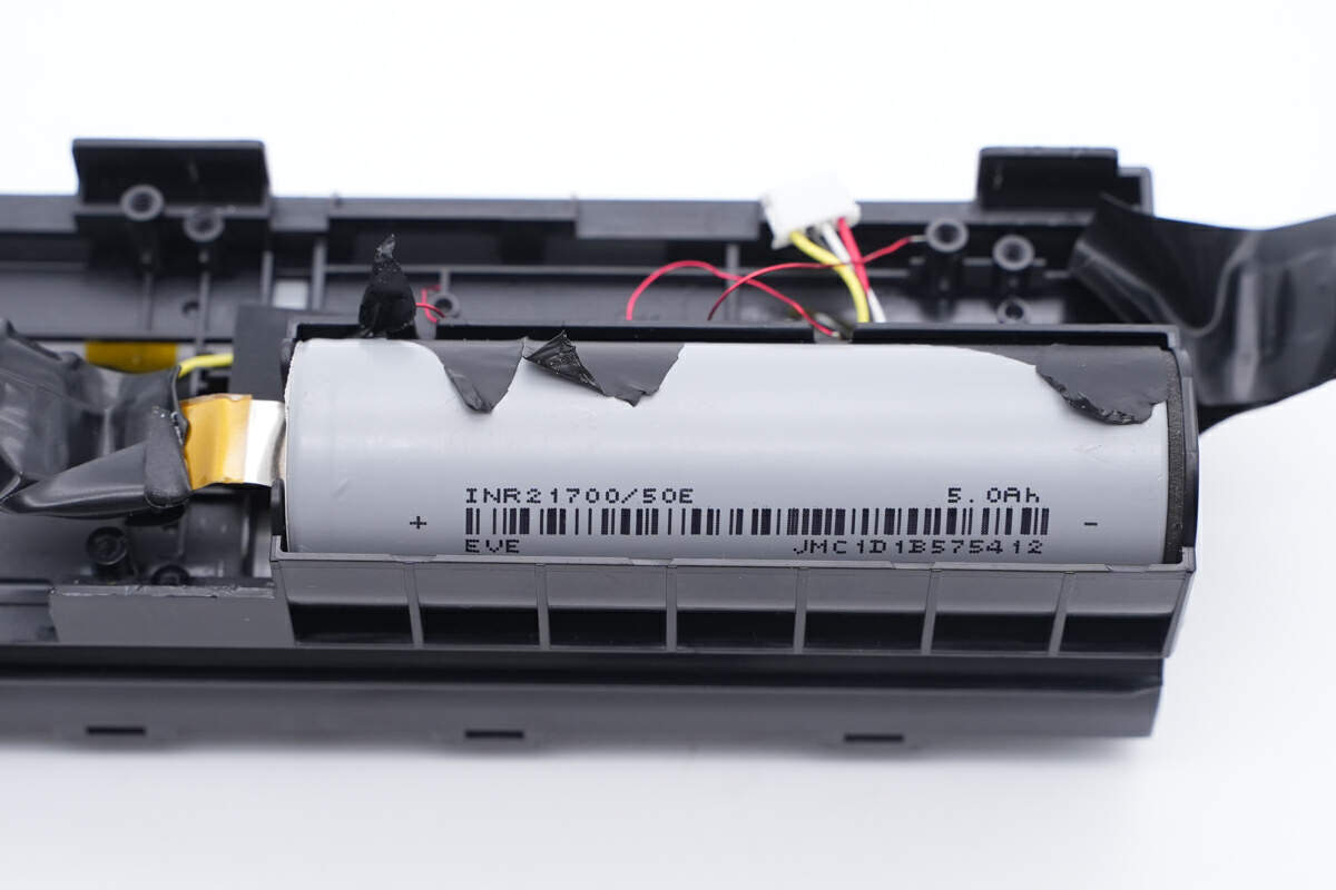
Those five 21700 battery cells are connected in series, from EVE. Rated capacity is 5000mAh.
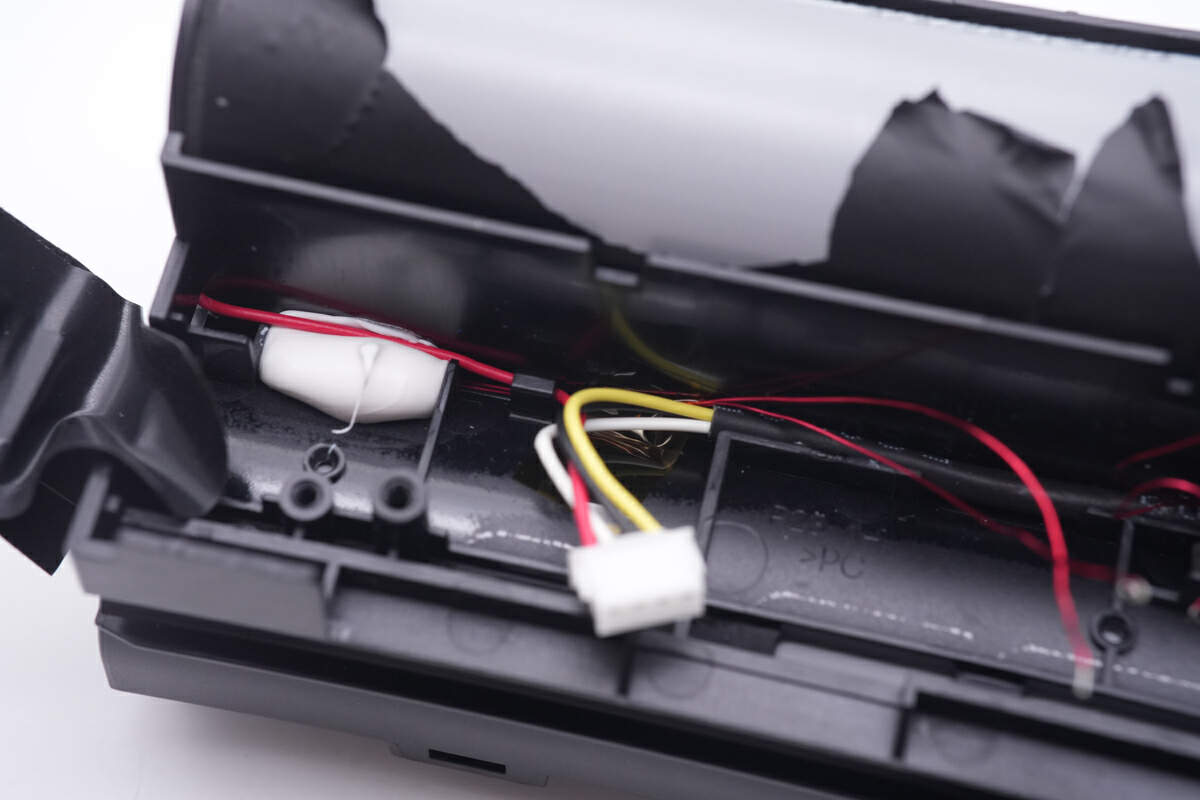
Some thermistors are placed between different battery cells.
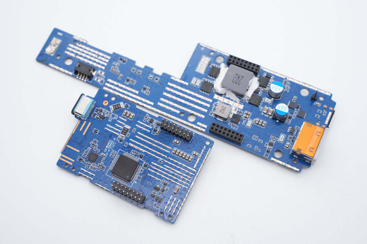
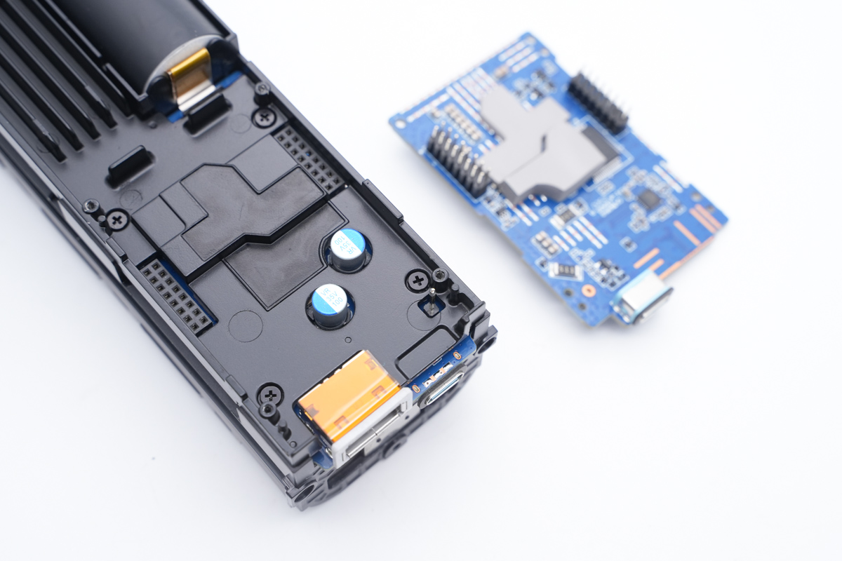
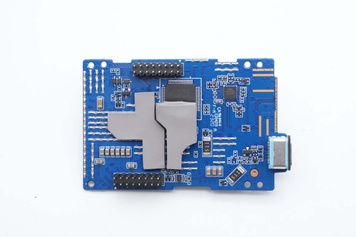
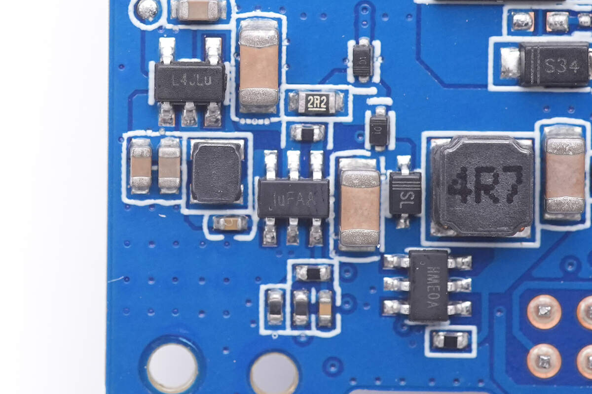
Then, let's check the first smaller PCB, which is used for the output of USB-C2.
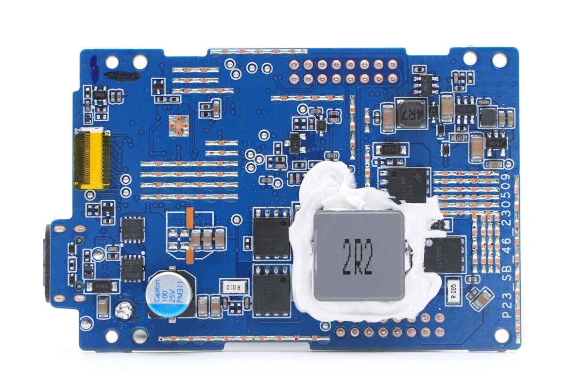
The VBUS MOSFET, filter capacitor, synchronous buck-boost MOSFETs, alloy inductor and buck circuit are on the front side of the PCB.
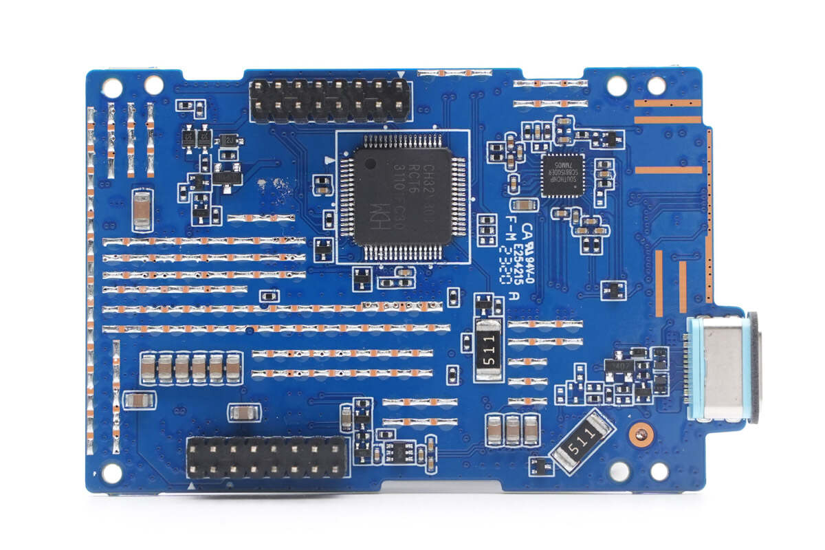
The MCU, synchronous buck-boost controller and USB-C2 socket are on the other side, and it's connected to the larger PCB by those pins.
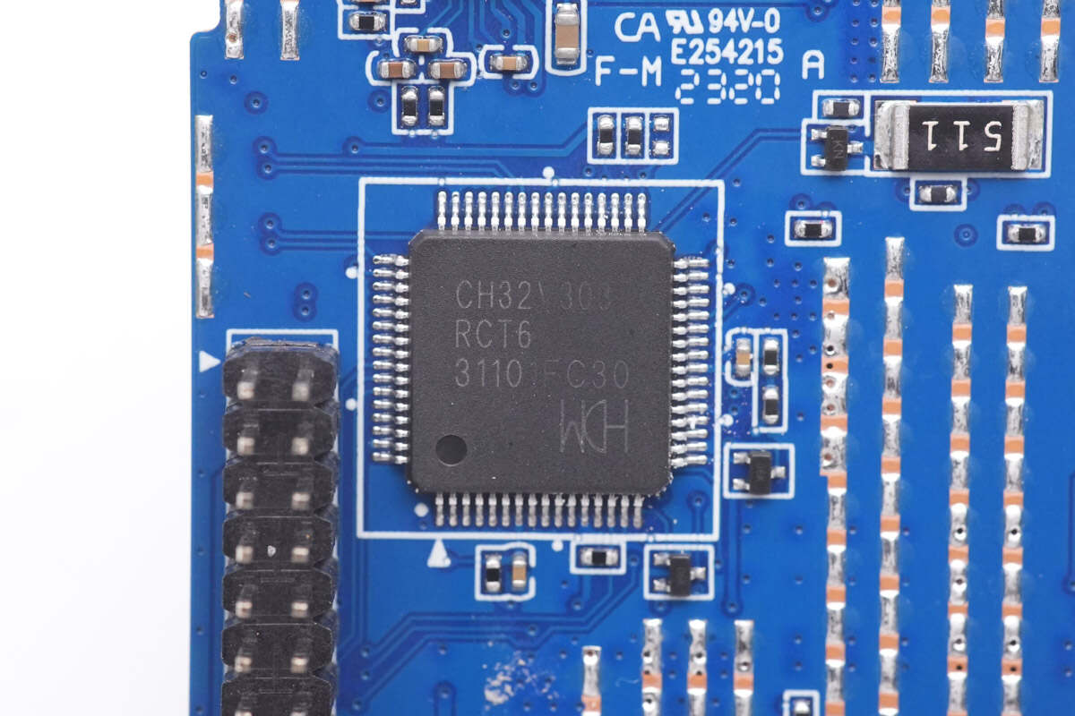
The MCU is from WCH, which is an industrial-grade enhanced MCU based on 32-bit RISC-V instruction set and architecture. Model is CH32V303RCT6.
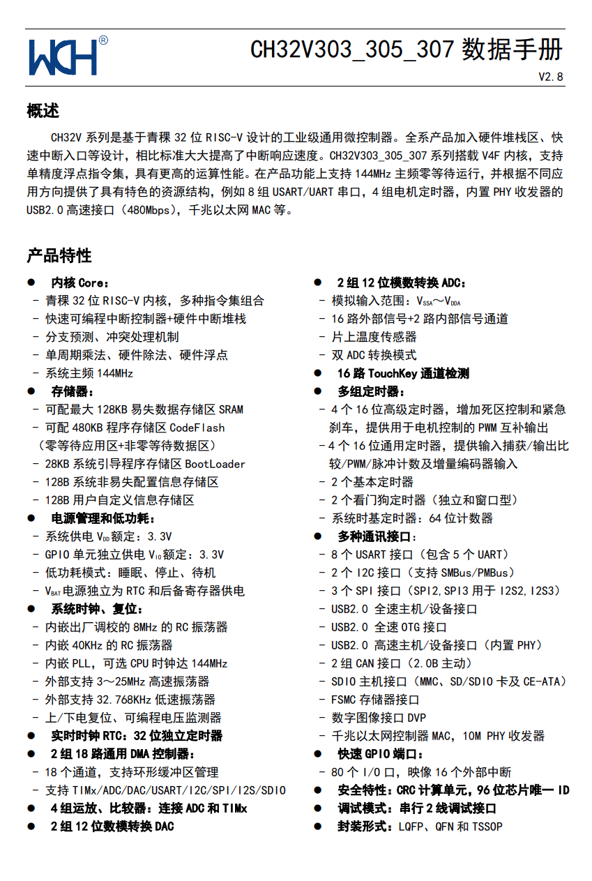
Here is all the information about WCH CH32V303RCT6.
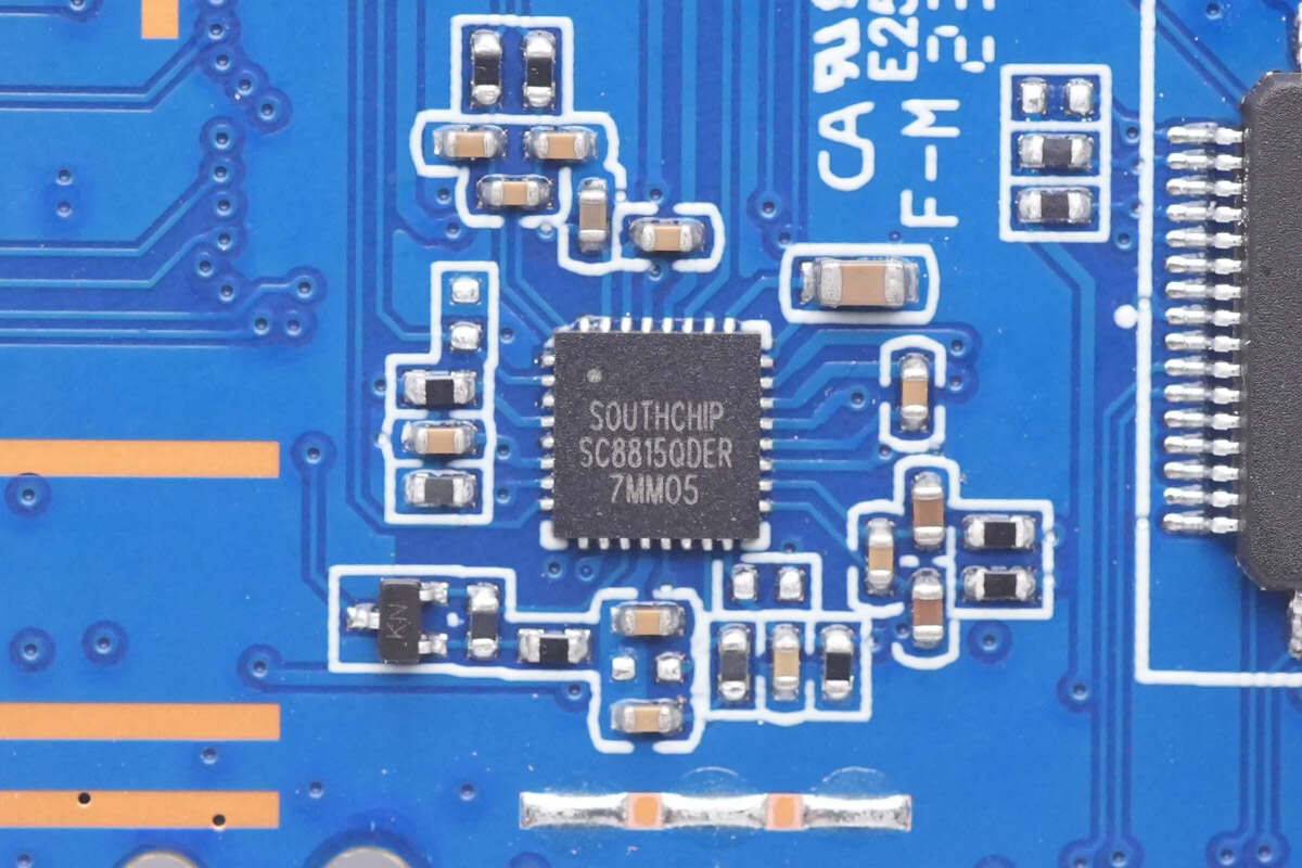
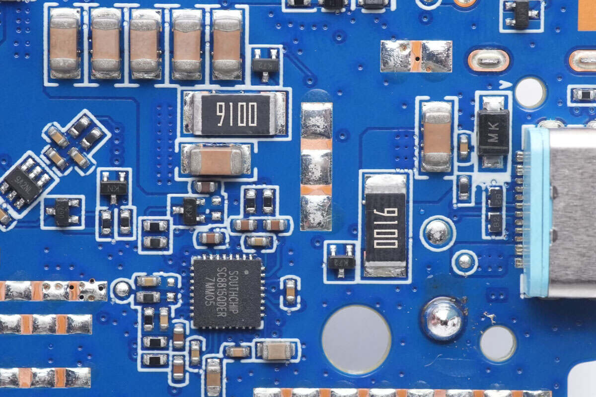
The buck-boost controller of USB-C2 is from Southchip, which is used to buck-boost the input DC voltage. Model is SC8815.
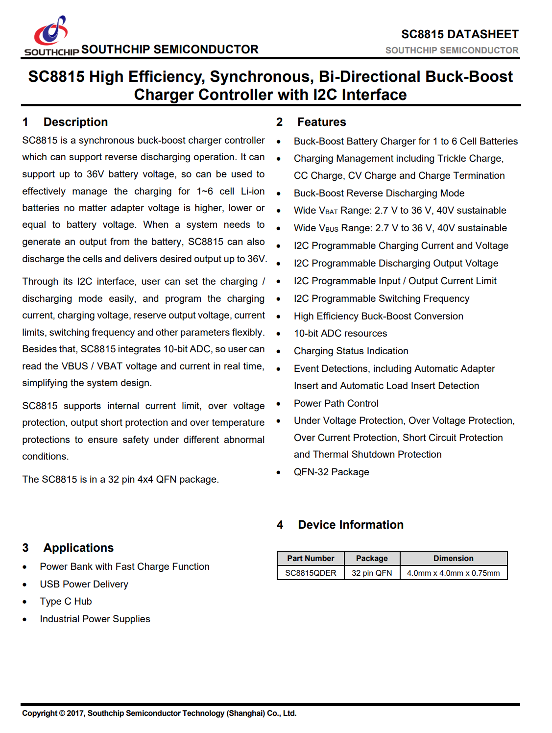
Here is all the information about the Southchip SC8815.
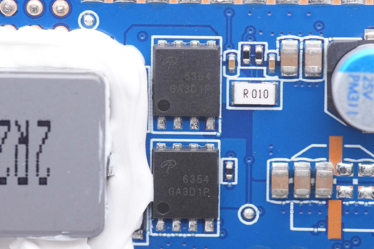
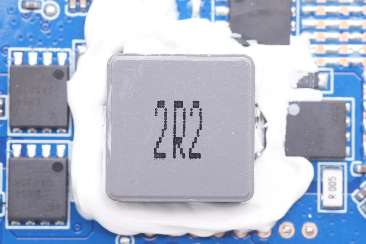
There're four synchronous buck-boost MOSFETs around the 2.2μH alloy inductor. They are from AOS and adopt DFN5 x 6 package. 30V, 2.75mΩ for each. Model is AON6354.
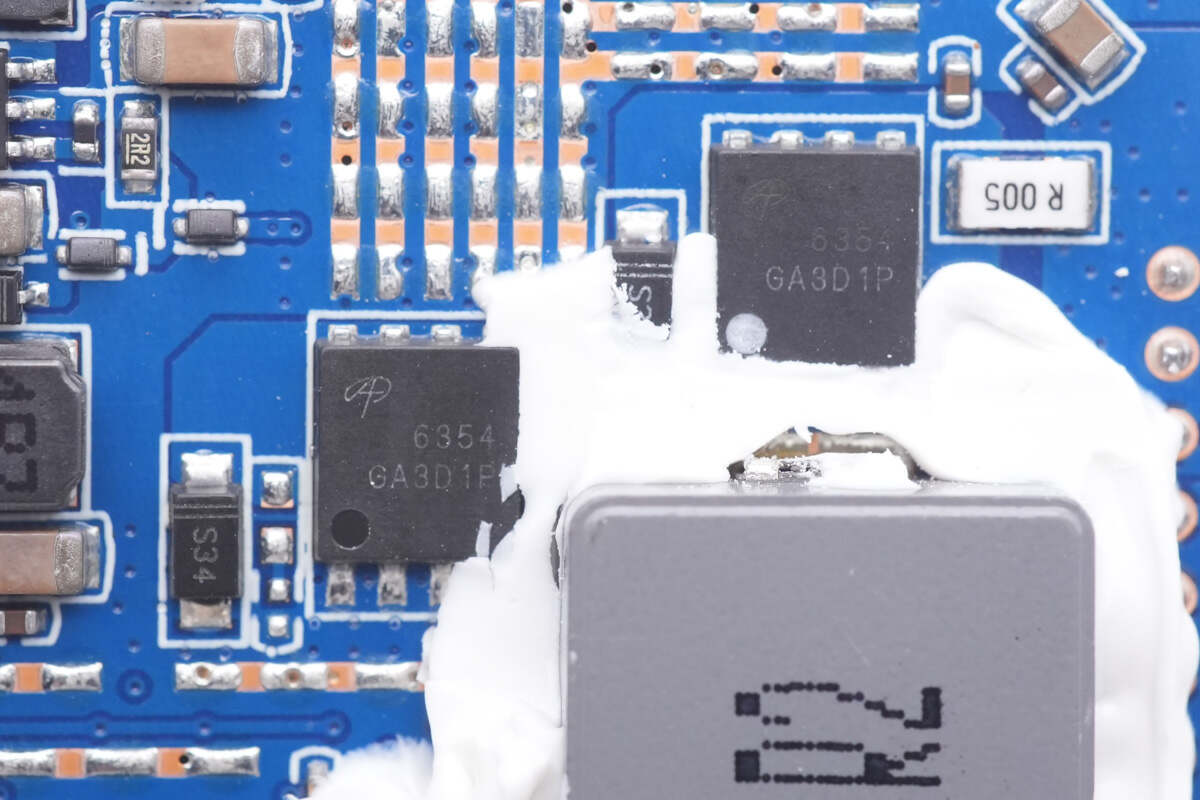
Here is the other two.
And those white silicone adhesives can enhance heat dissipation.
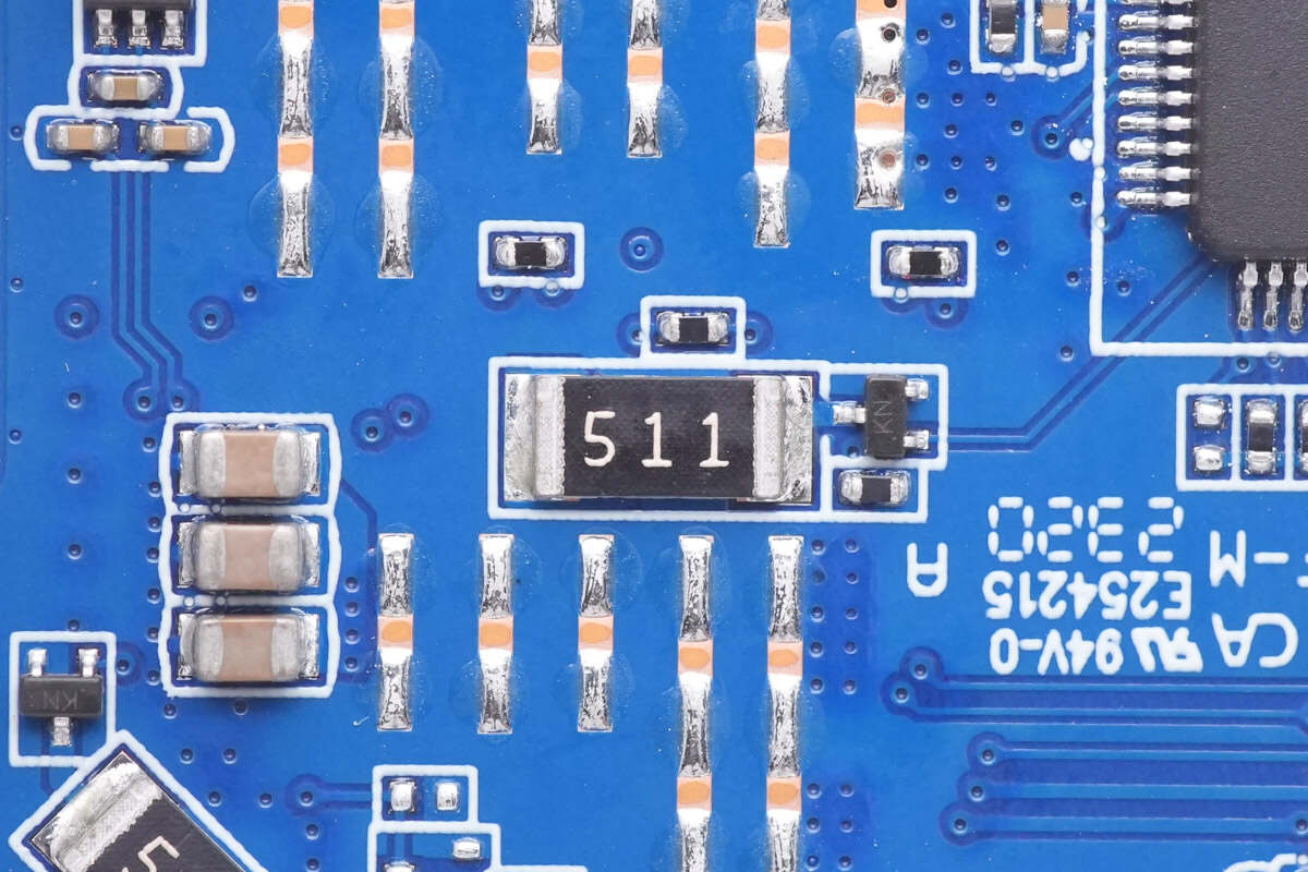
This is a 5.1K discharge resistor.
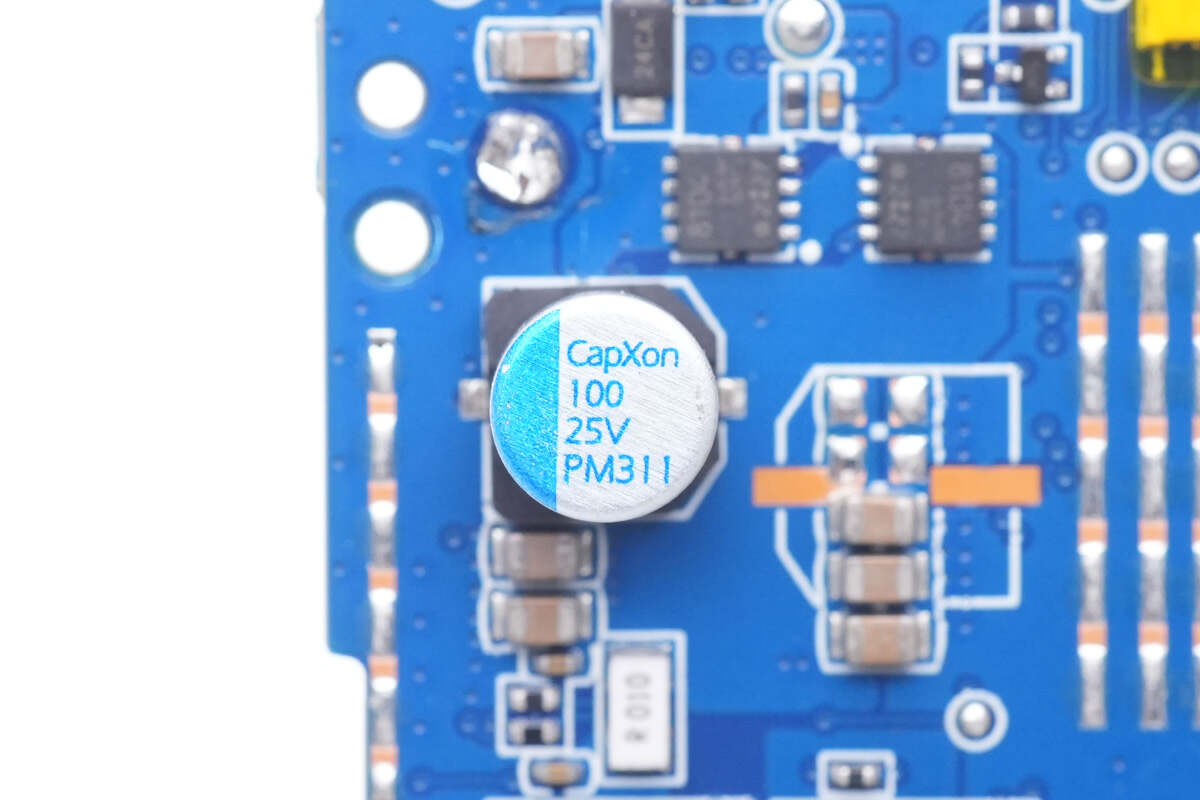
The solid capacitor for output filtering is from CapXon. 100μF 25V.
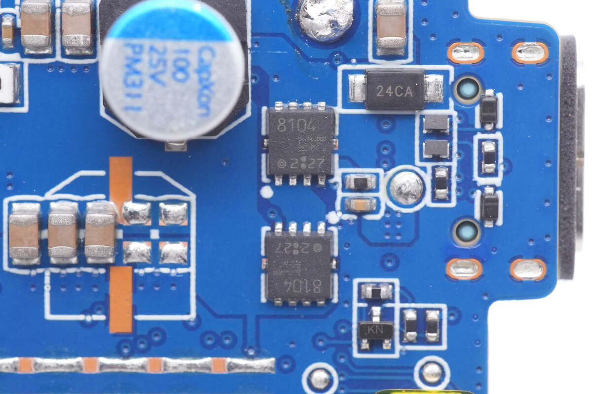
Two VBUS MOSFETs are used for USB-C2 output. Model is TPCC8104.
The plastic sheet inside the USB-C2 socket is blue.
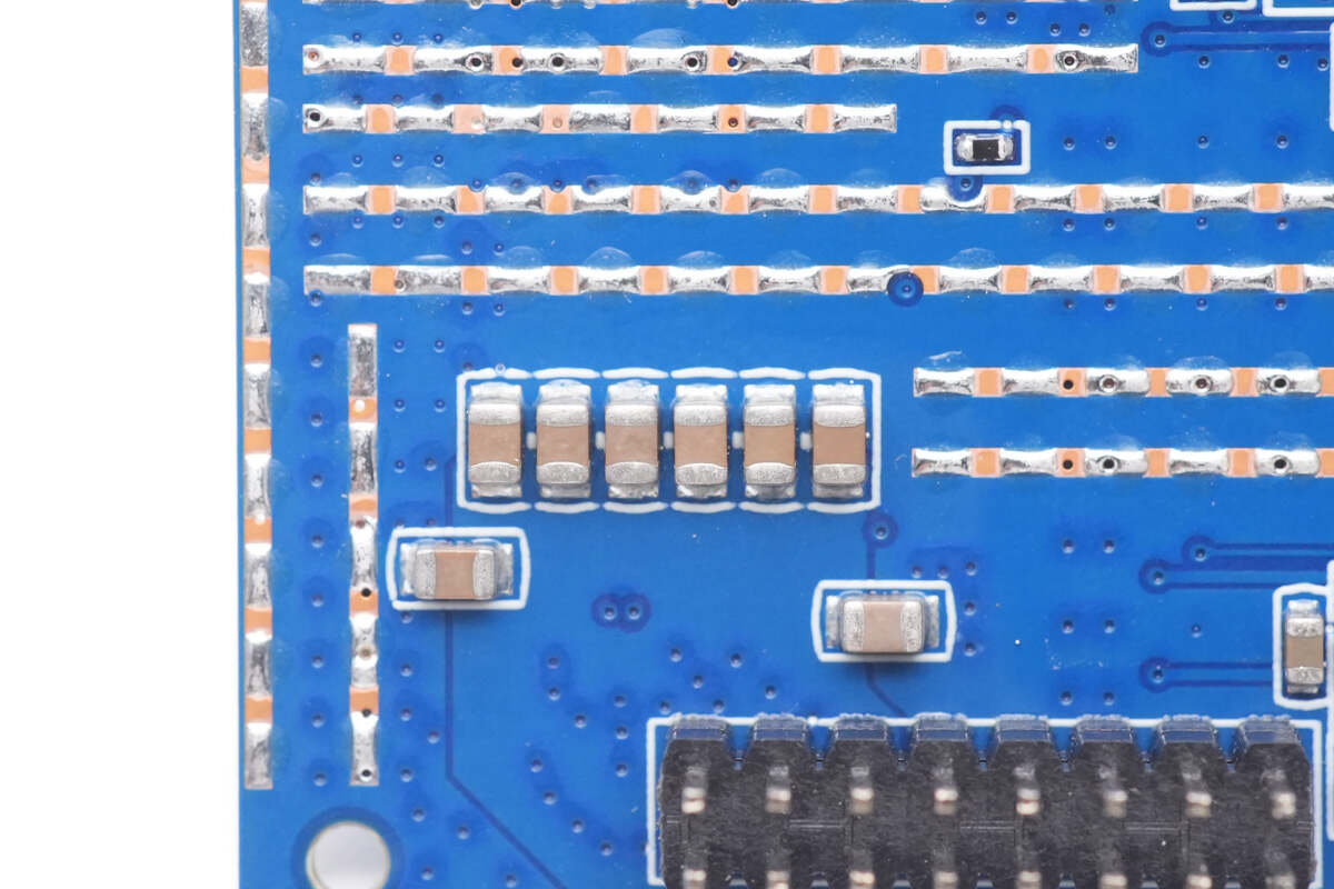
Those eight MLCC capacitors are connected in parallel for filtering.
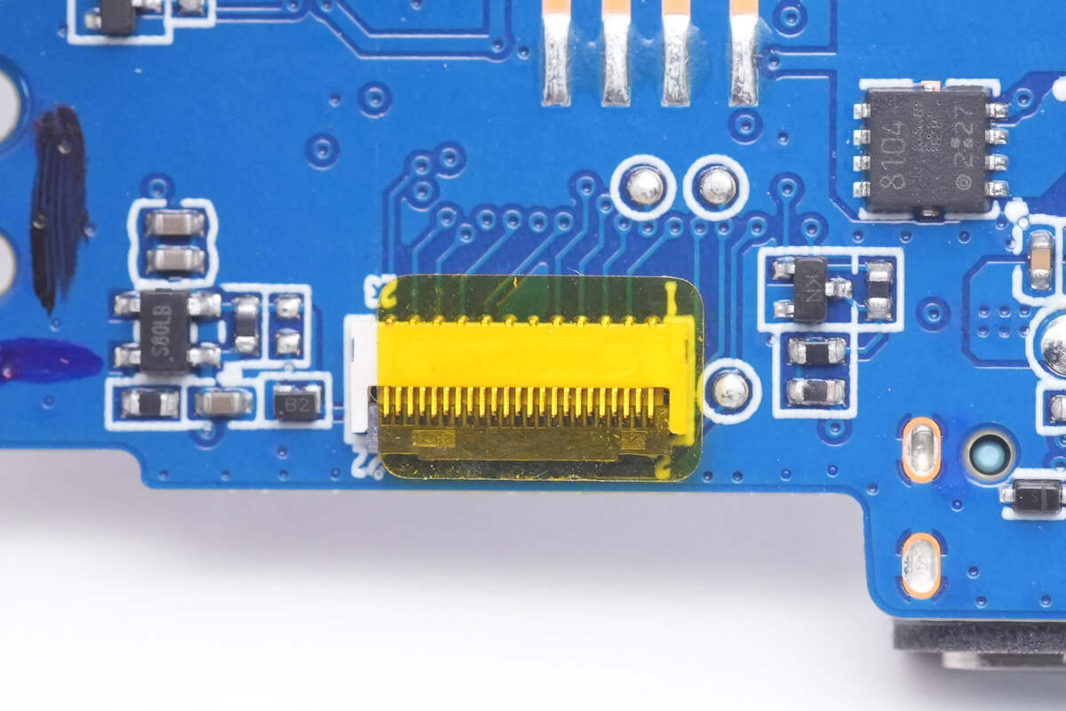
The connector of the display is pasted with yellow heat-resistant tape.
Here is the buck circuit that powers the controller and MCU.
Then, let's move on to the larger PCB, which is used for the output of USB-C1 and USB-A.
The tinned coppers are exposed on the front and back of the PCB to enhance heat dissipation.
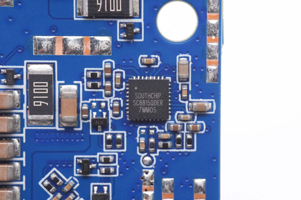
The buck-boost controller for the USB-C1 140W is also from Southchip, same as the USB-C2.
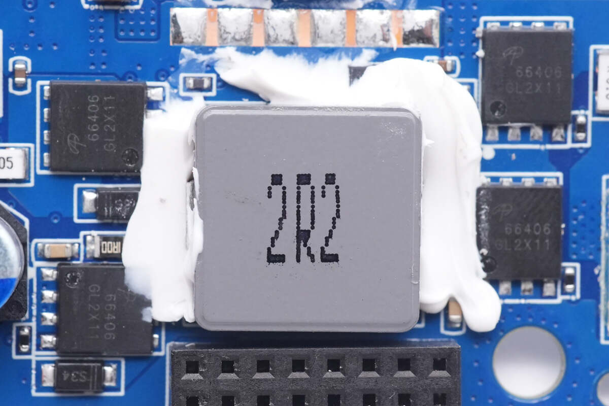
Like the USB-C2, four synchronous buck-boost MOSFETs are around the 2.2μH alloy inductor.
They're all from AOS and adopt DFN5 x 6 package.
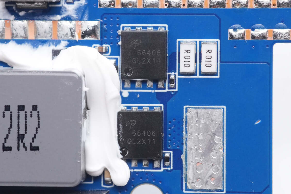
40V, 5mΩ. Model is AONS66406.
The other two have the same model.
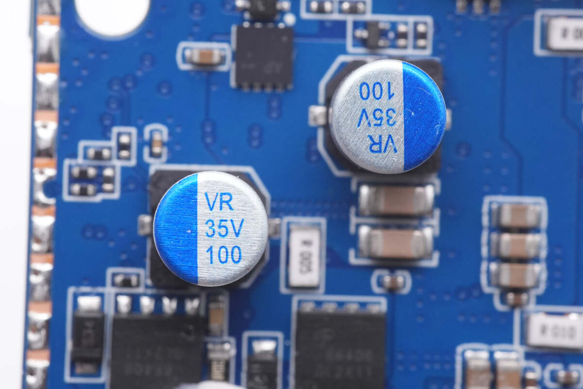
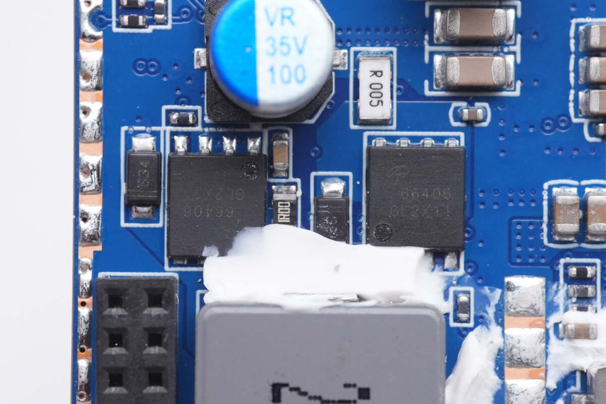
Two solid capacitors for output filtering are connected in parallel. 35V 100μF.
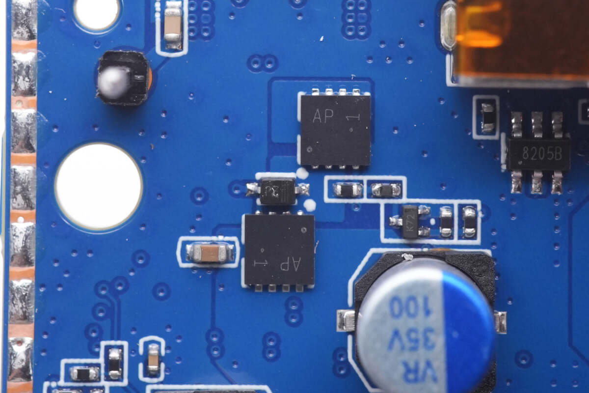
Two output VBUS MOSFETs of USB-C1 are connected in series, marked with AP 1.
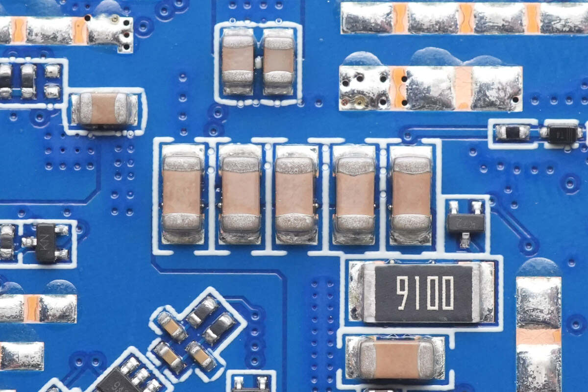
Those MLCC capacitors are also connected in parallel for filtering, just like the last PCB.
These are resistors used for output and Transient Voltage Suppressor (TVS) components for overvoltage protection.
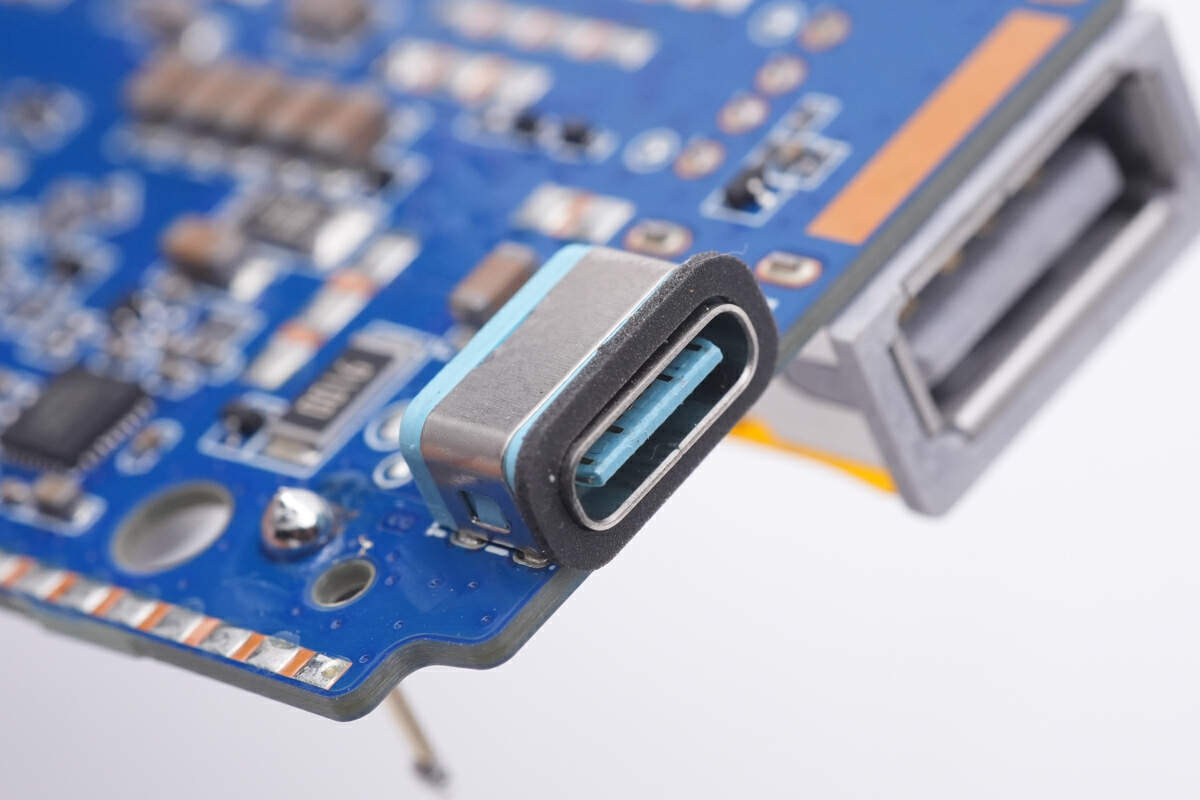
The plastic sheet inside the USB-C1 socket is also blue.
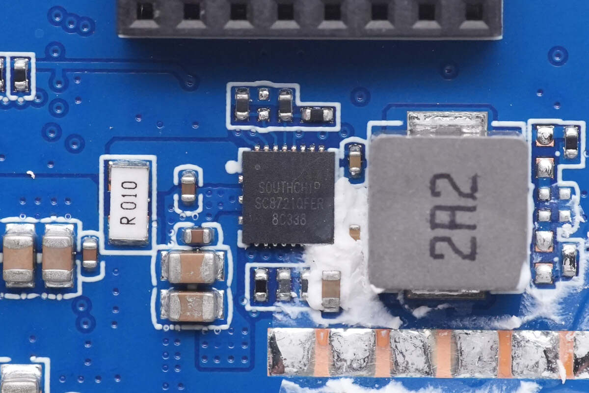
And the synchronous buck-boost controller of USB-A is from Southchip. It integrates four buck-boost MOSFETs to form an H-bridge, the input and output voltage is between 2.7-22V. It also supports wide input and output voltage range, output current limit, dynamic output voltage adjustment, internal current limit, output short protection and over temperature protections to ensure safety under different abnormal conditions. And the model is SC8721.
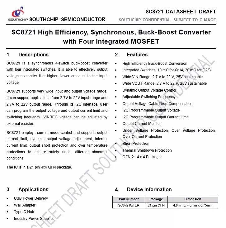
Here is all the information about the Southchip SC8721.
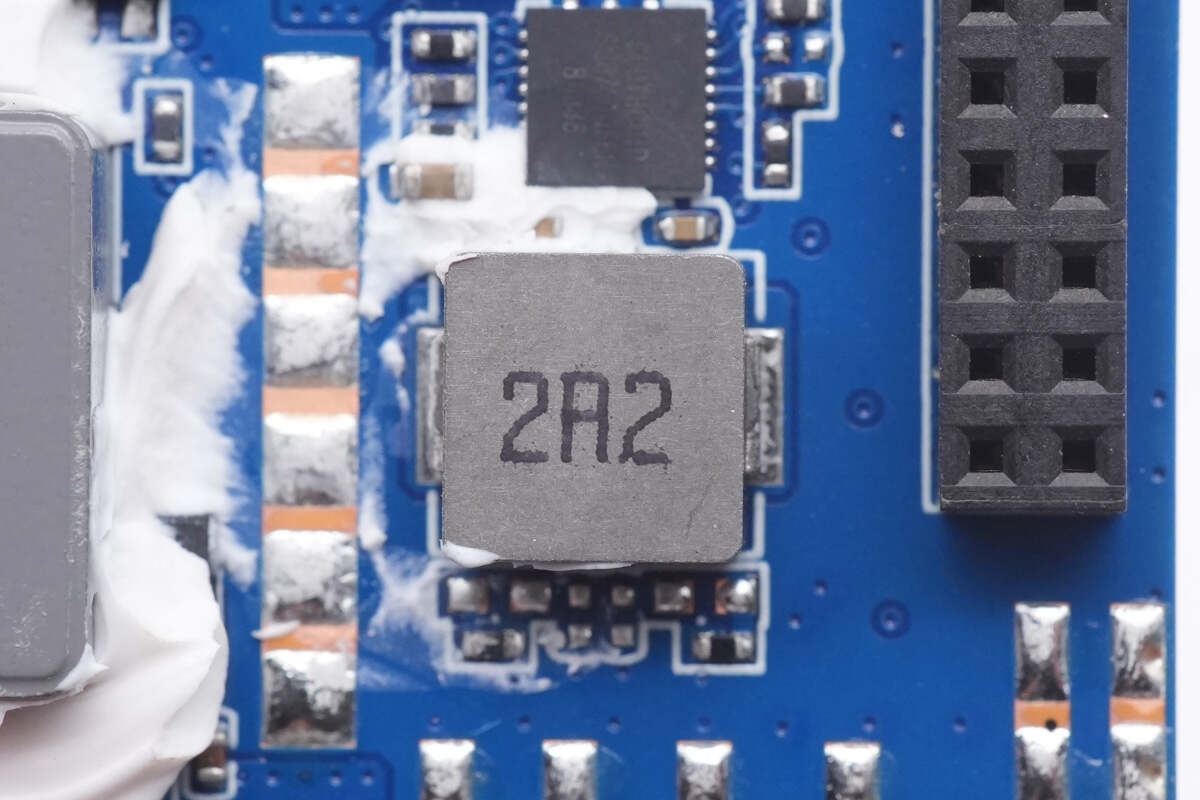
The buck-boost alloy inductor for USB-A is smaller than that of two USB-C ports.
The output VBUS MOSFET of USB-A is next to the USB-A connector.
And the USB-A connector is pasted with heat-resistant tape.
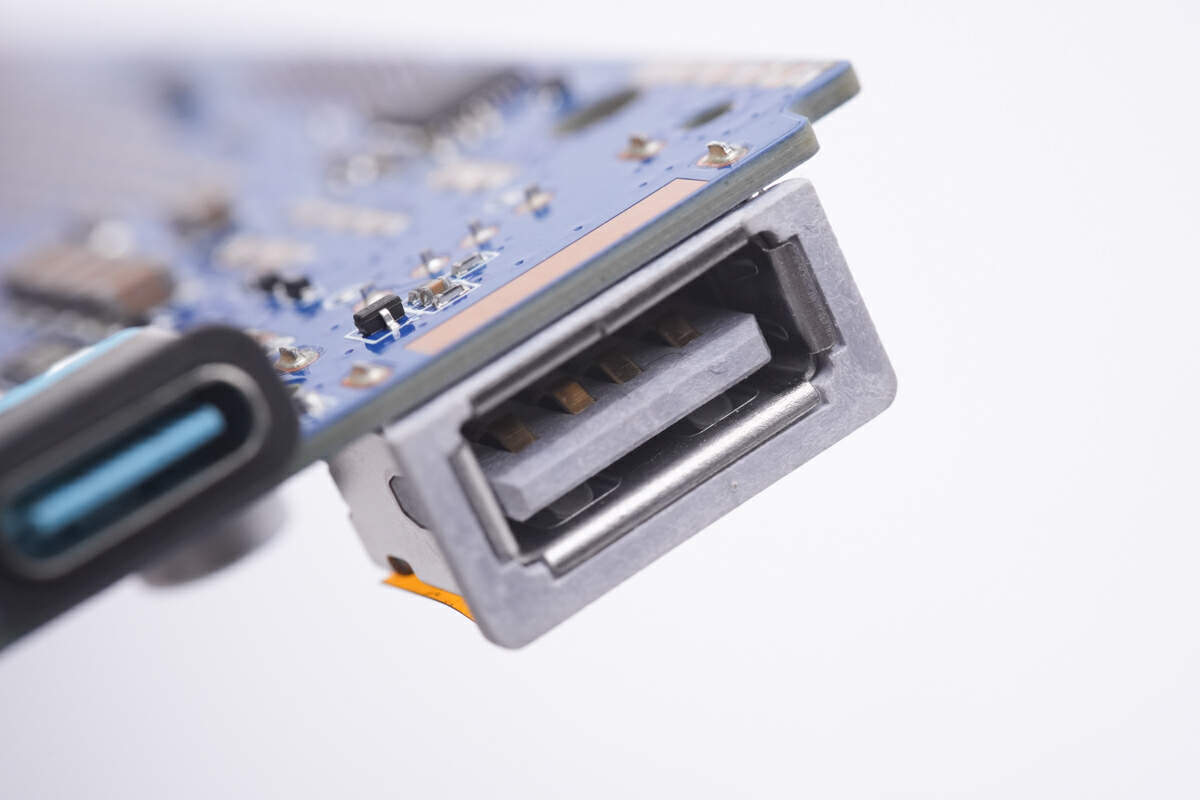
And the plastic sheet inside the USB-A socket is white.
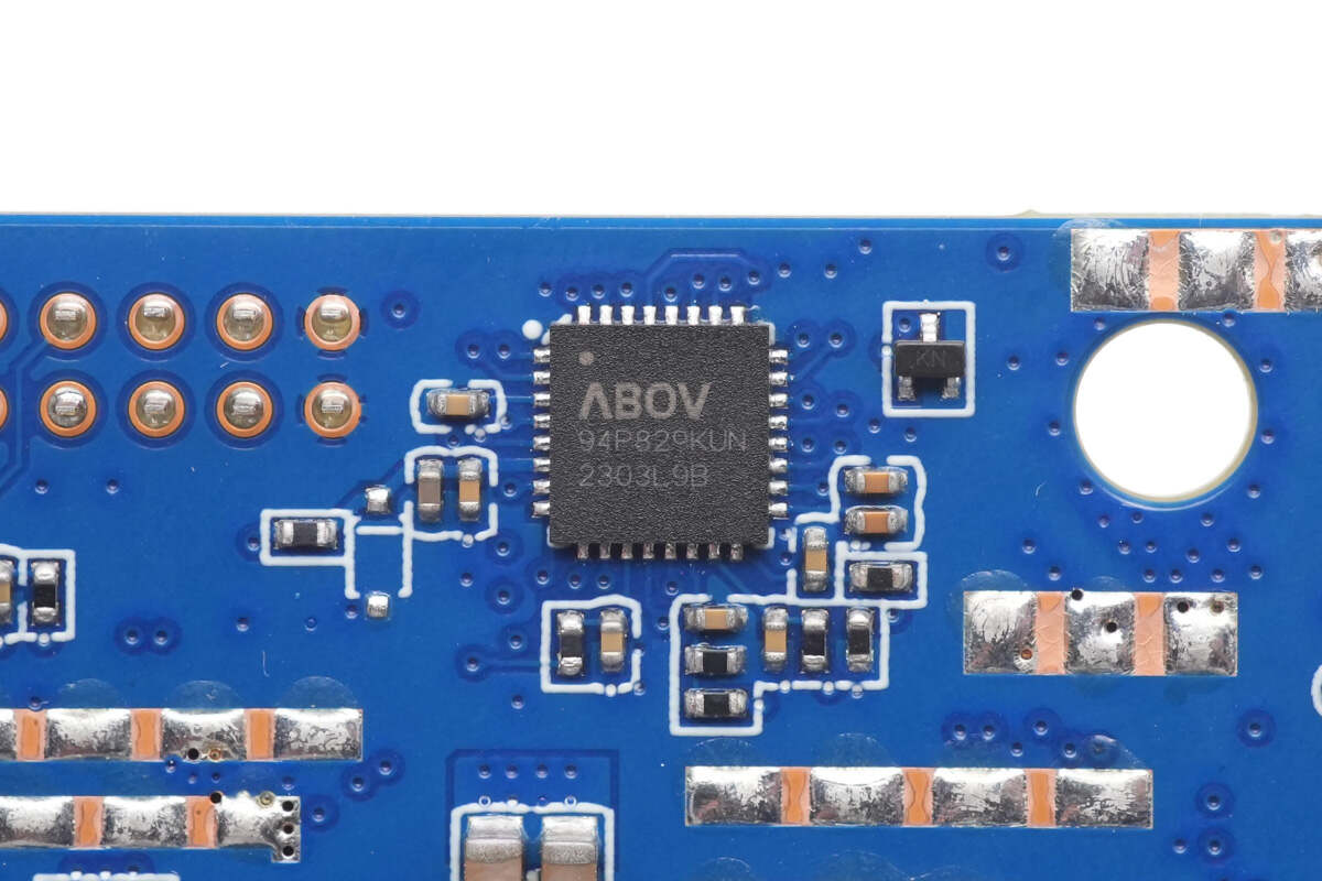
The protocol chip is actually an MCU with an 8051 core, from ABOV. It supports PD3.1 and a wide range of fast charging protocols. Model is A94P829.
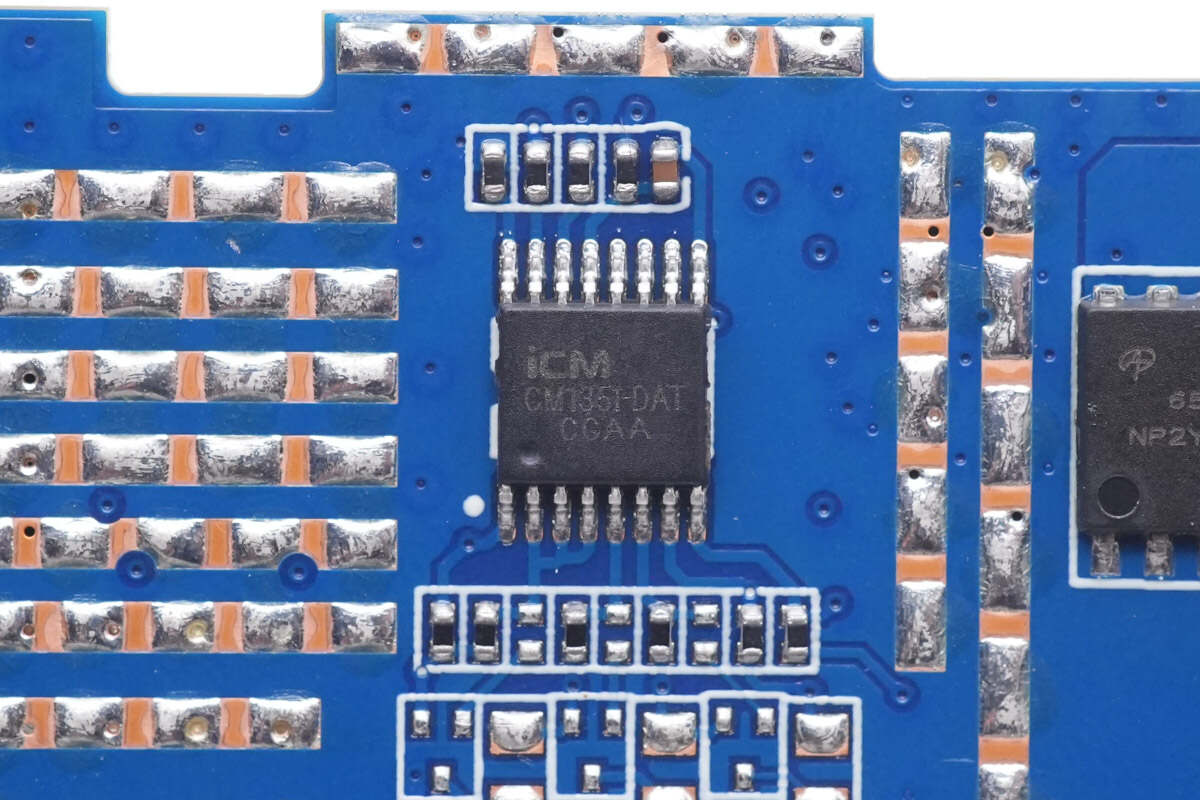
The battery protection chip is from iCM, which is also seen on other power banks, like the UGREEN 145W Superbox Laptop Power Bank. It integrates high-precision voltage & current detection circuits and can protect the battery cells. Model is CM1351.
Here is all the information about the ICM CM1351.
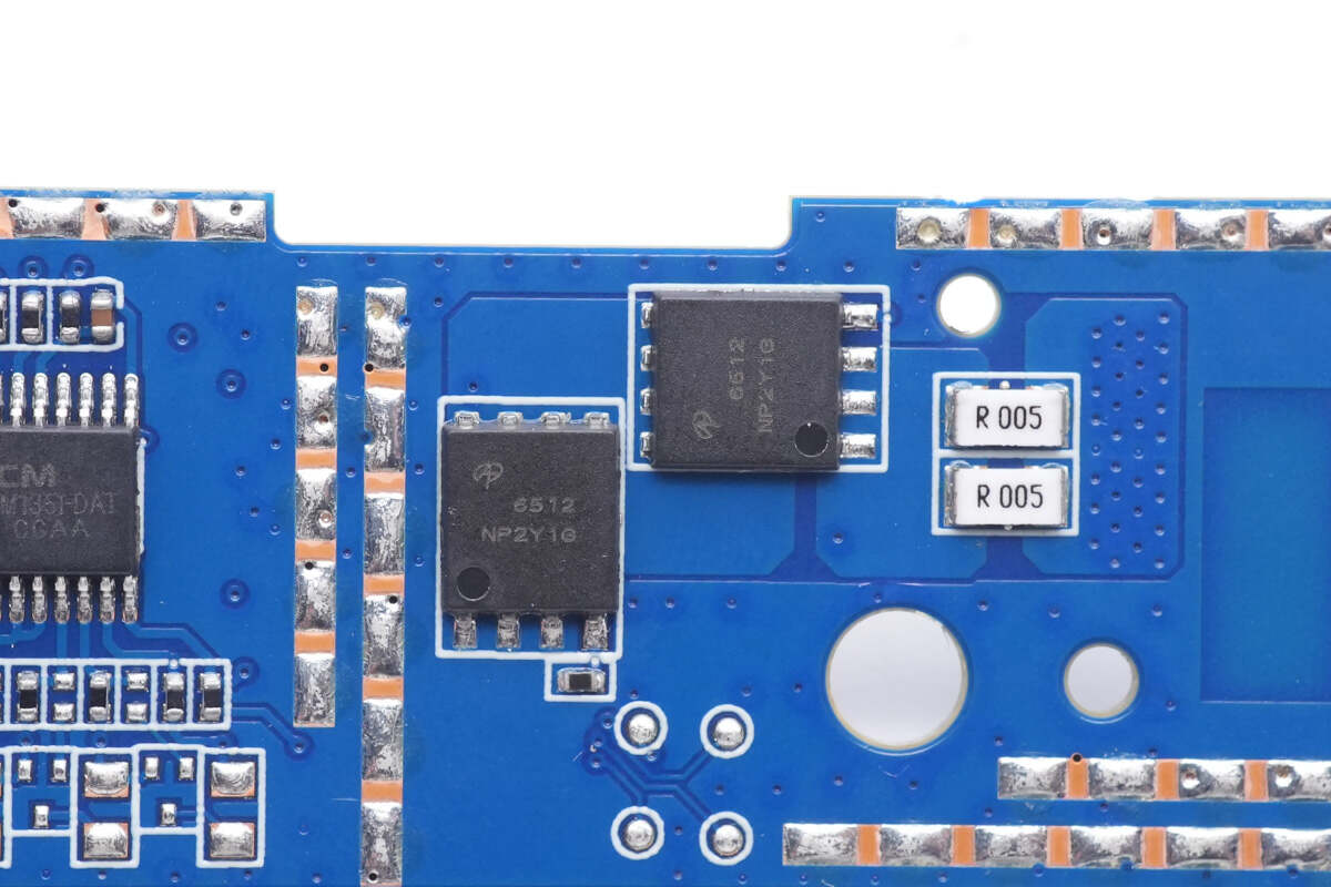
Those two battery protection MOSFETs are from AOS and adopt DFN5 x 6 package. 30V, 1.4mΩ. Model is AON6512.
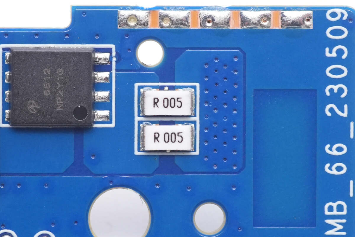
Two 5mΩ resistors are connected in parallel for current detection of battery pack.
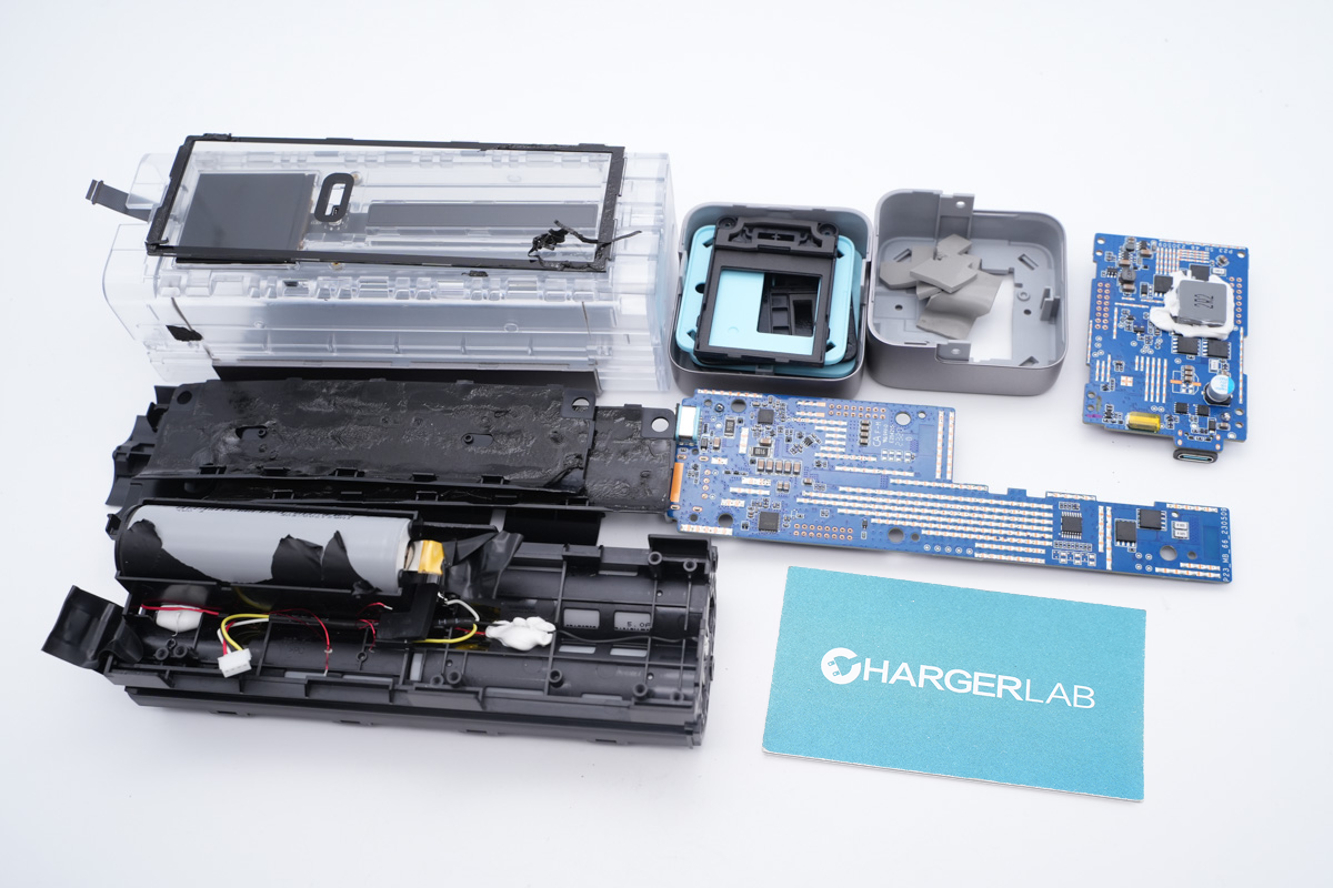
Well, that's all components of the CUKTECH No.20 PD3.1 power bank.
Summary of ChargerLAB
The CUKTECH No.20 PD3.1 & 210W Power Bank is equipped with three output ports and has a large capacity of 25000mAh. The USB-C1 supports PD3.1 and can provide up to 140W output power, which is very rare in the market.
After taking it apart, we found it integrates five battery cells, and two PCBs are stacked together to make the power bank smaller. You can also check the real-time charging status through the color display on the front at a glance.
Related Articles:
1. Teardown of CUKTECH No.20 PD3.1 & 210W Power Bank (Video)
2. Teardown of CUKTECH No.30 PD3.1 & 300W Power Bank
3. CUKTECH Launched No. 30 Power Bank at Hong Kong Electronics Show