Introduction
Baseus has launched a 145W high-power portable charger featuring dual built-in USB-C cables and a digital display. Its innovative integrated latch design allows for cable storage while doubling as a carrying strap, balancing portability with practicality. The device houses a 25,000mAh high-capacity battery and supports PD3.1 fast charging, offering 28V/5A output with a maximum power output of 145W.
In addition to supporting 100W PD through the USB-C ports and cables, it is also compatible with Xiaomi’s 90W Surge Protocol. Below, Charging Head Network provides a detailed teardown of the product, examining its internal components and build quality.
Product Appearance
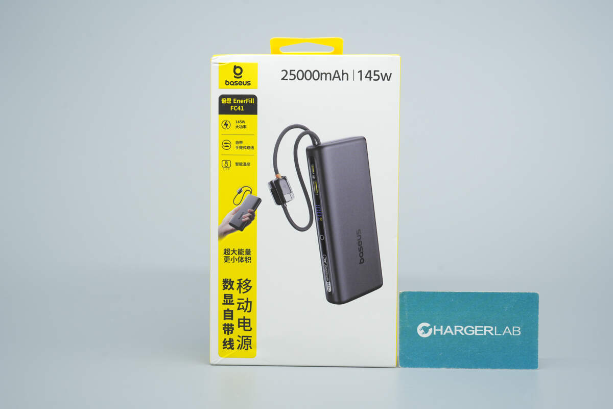
The front of the packaging features the Baseus logo, the product name, key selling points, and an image of the device.
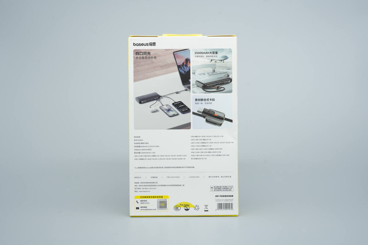
The back of the packaging displays usage scenarios and technical specifications.

The package includes the portable charger, a user manual, a warranty card, and a cartoon sticker.
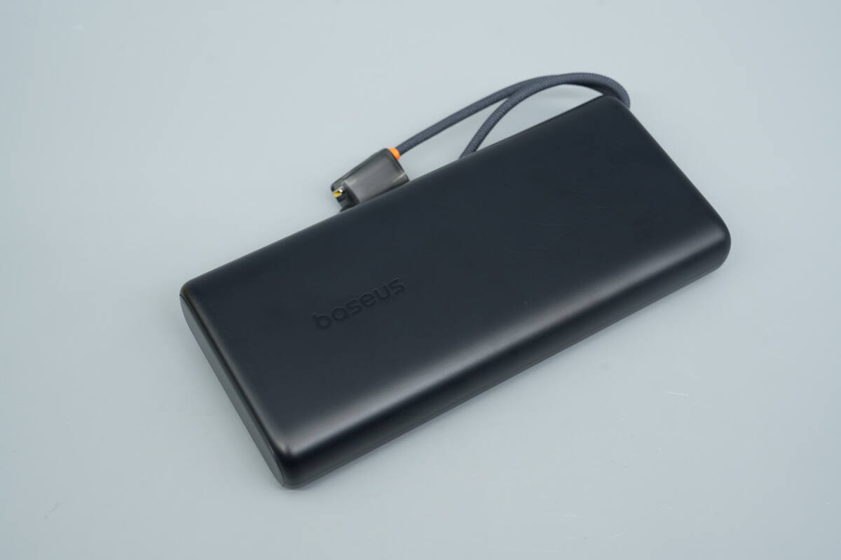
The portable charger comes with two built-in USB-C cables and features a matte finish on a PC flame-retardant casing.
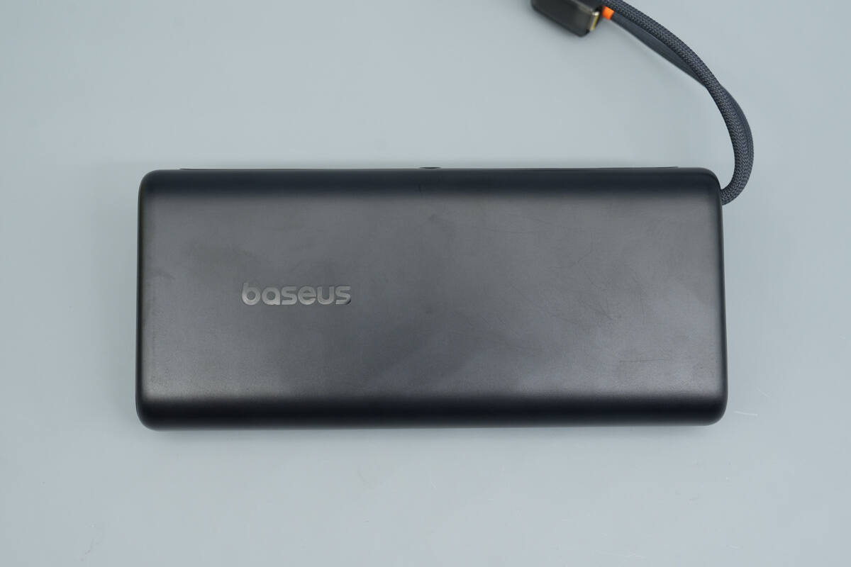
The front features the Baseus logo.
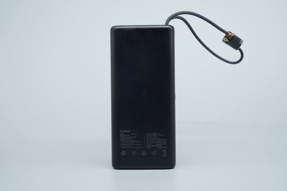
The back displays the technical specifications.
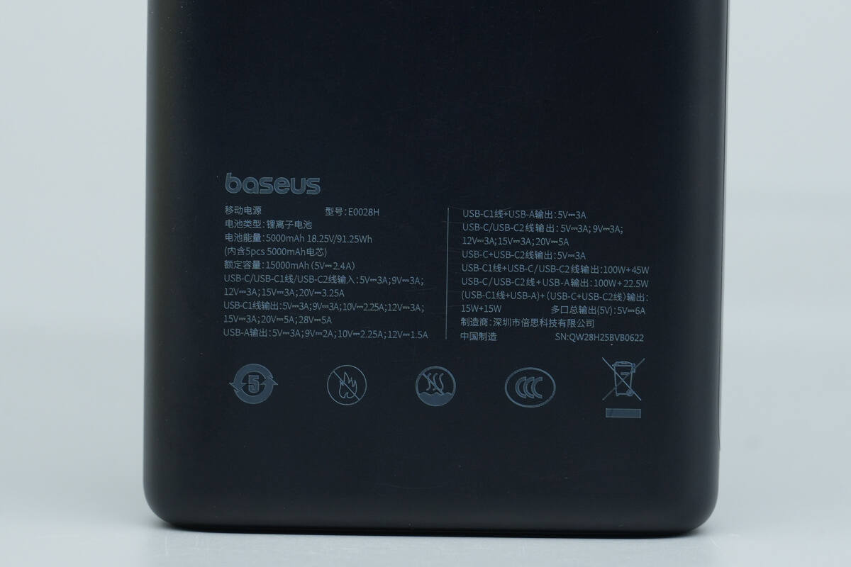
Model: E0028H
Battery Type: Lithium-ion battery
Battery Energy: 5000mAh 18.25V / 91.25Wh (contains 5 × 5000mAh cells)
Rated Capacity: 15,000mAh (5V 2.4A)
Input:
USB-C / USB-C1 Cable / USB-C2 Cable: 5V 3A, 9V 3A, 12V 3A, 15V 3A, 20V 3.25A
Output:
USB-C1 Cable: 5V 3A, 9V 3A, 10V 2.25A, 12V 3A, 15V 3A, 20V 5A, 28V 5A
USB-A: 5V 3A, 9V 2A, 10V 2.25A, 12V 1.5A
USB-C1 Cable + USB-A: 5V 3A
USB-C / USB-C2 Cable: 5V 3A, 9V 3A, 12V 3A, 15V 3A, 20V 5A
USB-C + USB-C2 Cable: 5V 3A
USB-C1 Cable + USB-C / USB-C2 Cable Output: 100W + 45W
USB-C / USB-C2 Cable + USB-A: 100W + 22.5W
(USB-C1 Cable + USB-A) + (USB-C + USB-C2 Cable): 15W + 15W
Total Multi-Port Output (5V): 5V 6A

It has passed the CCC certification.
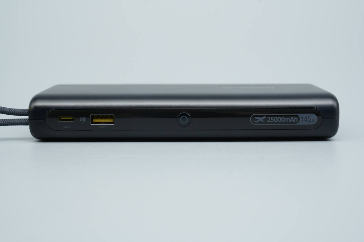
This side features a power button, one USB-A port, one USB-C port, and a digital display.

The ports use yellow plastic sheets.

The digital display shows the remaining battery level of the power bank.
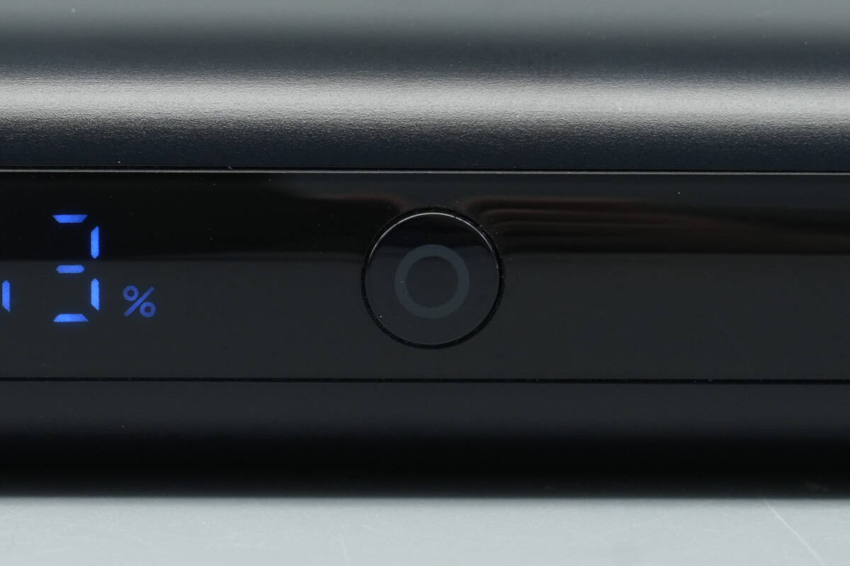
Close-up of the power button.
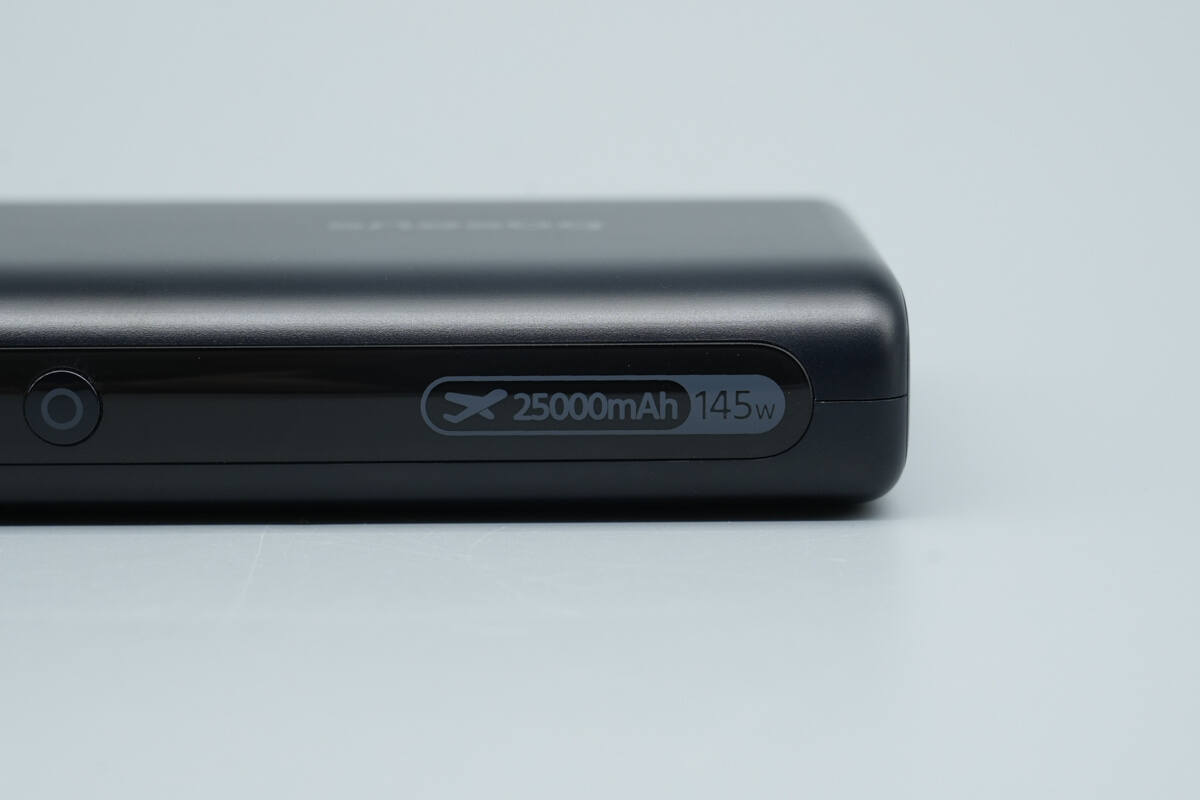
The right side displays “25,000mAh,” “145W,” and an airplane symbol, indicating that the power bank is allowed on flights.
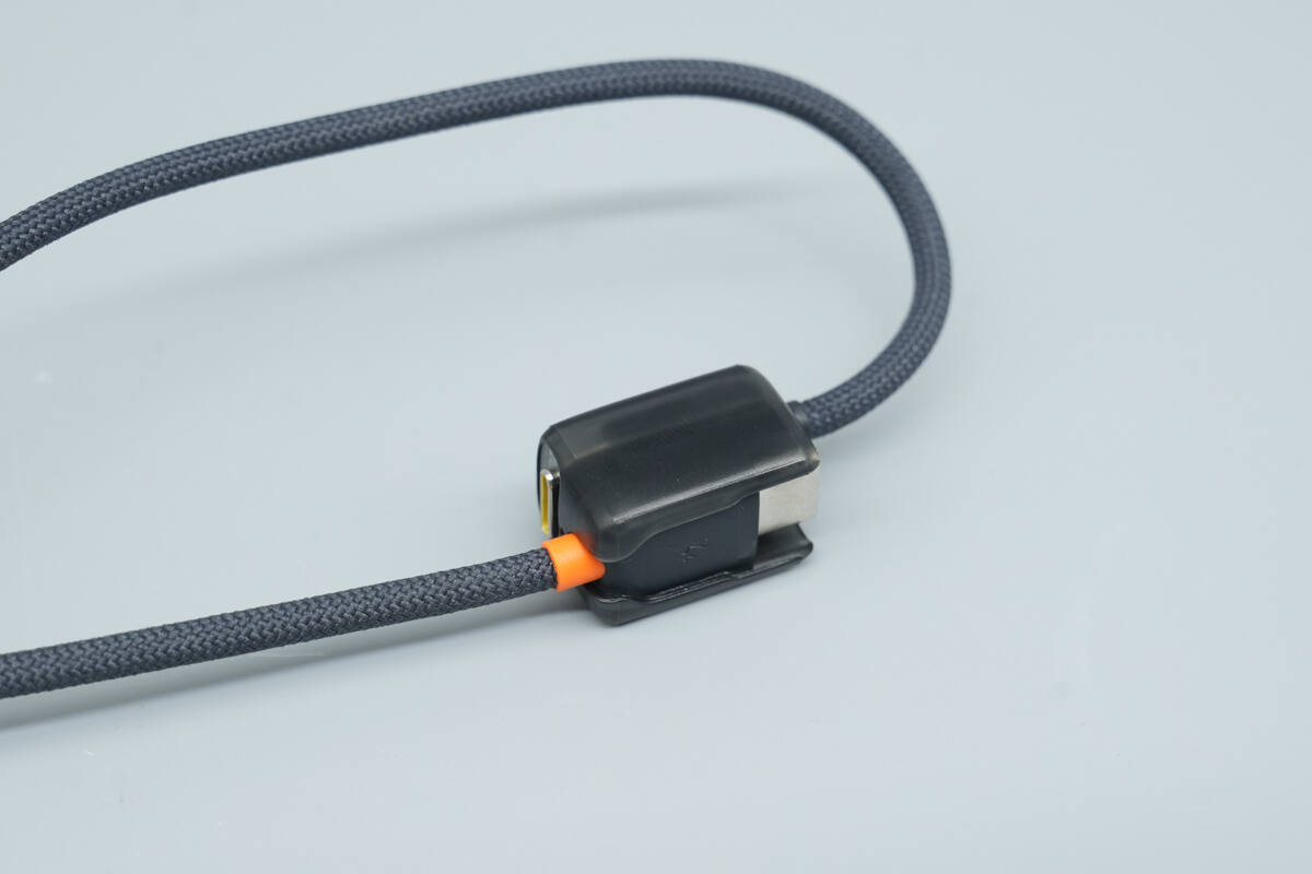
It features an integrated latch design, allowing the dual USB-C cables to be secured and used as a carrying strap.

The cables are braided.

The length of the power bank is about 164.82 mm (6.49 inches).

The width is about 75.07 mm (2.96 inches).
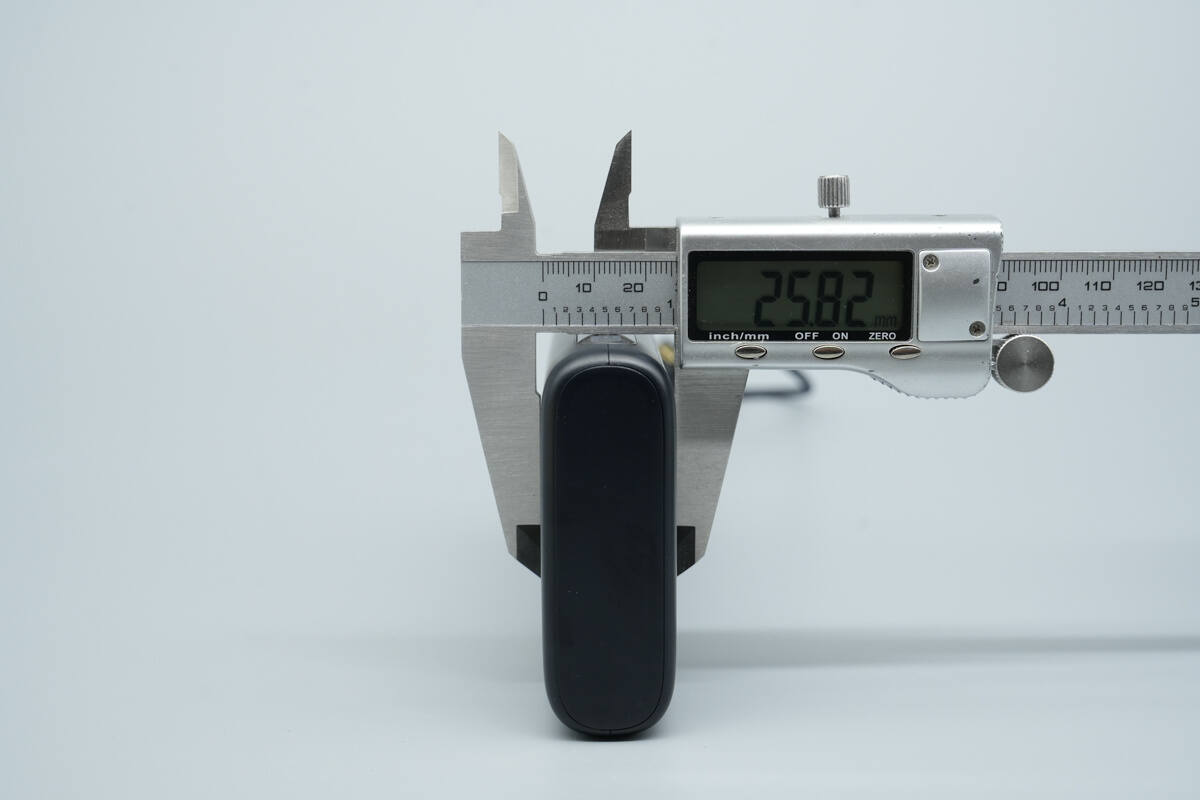
The thickness is about 25.82 mm (1.017 inches).
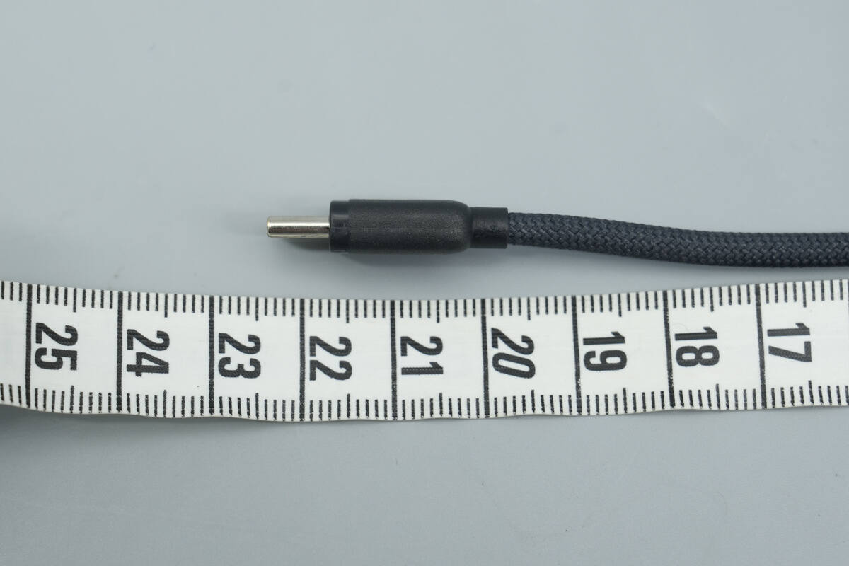
The length of the USB-C1 cable is about 22.5 cm (8.86 inches).

The length of the USB-C2 cable is about 12.5 cm (4.92 inches).
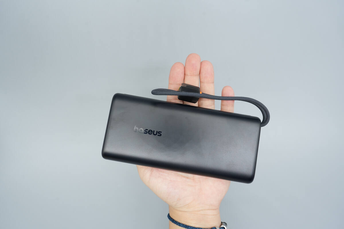
That's how big it is in the hand.
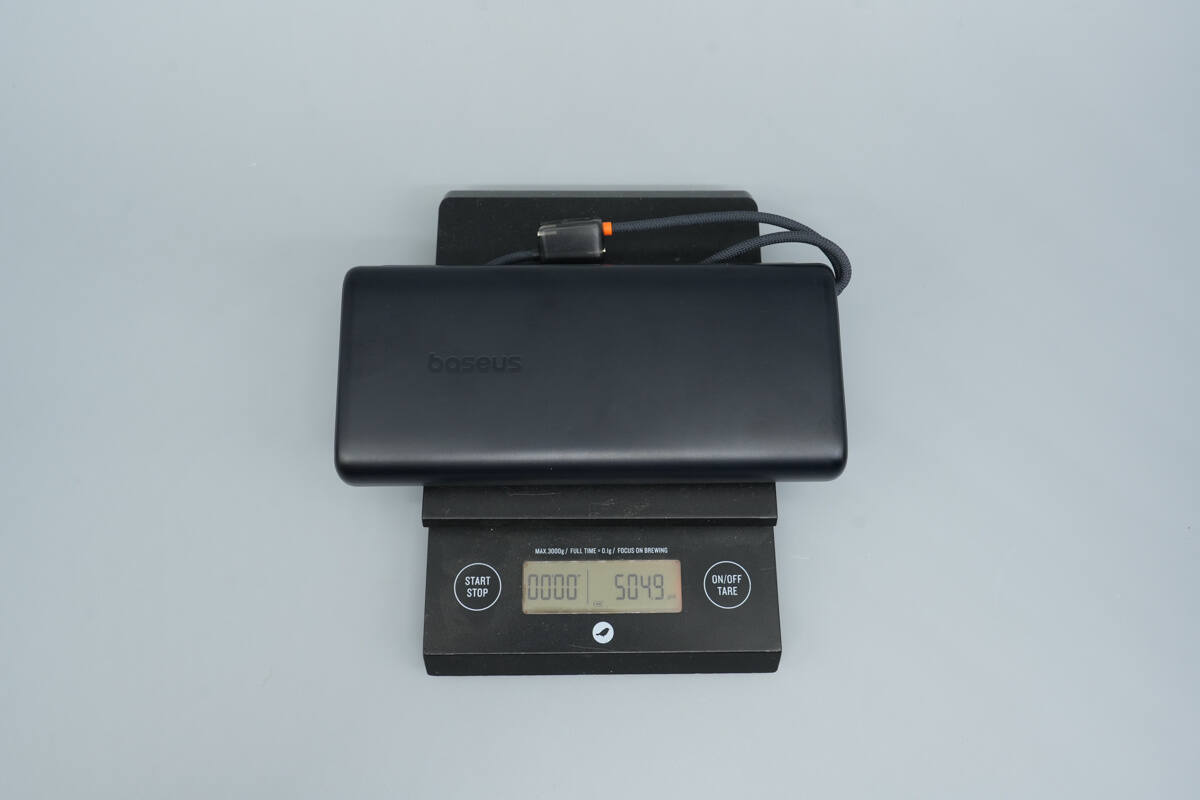
The weight is about 505 g (17.81 oz).

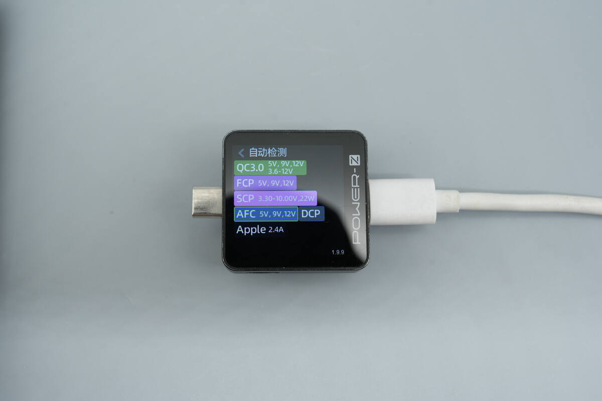
ChargerLAB POWER-Z KM003C shows that the USB-C1 cable supports QC3.0/5, FCP, SCP, AFC, PD3.1, PPS, DCP, and Apple 2.4A charging protocols.
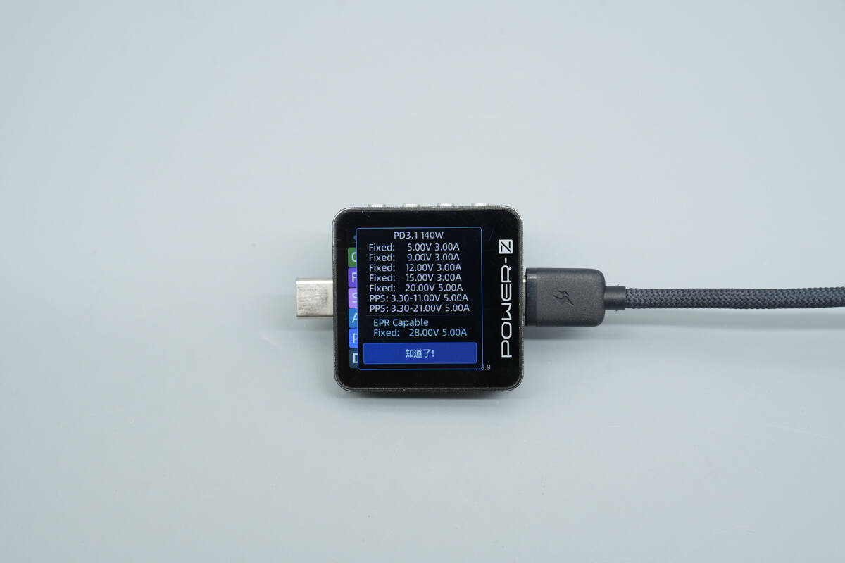
And it has six fixed PDOs of 5V3A, 9V3A, 12V3A, 15V3A, 20V5A, and 28V5A. It also has two sets of PPS, which are 3.3-11V5A and 3.3-21V5A.
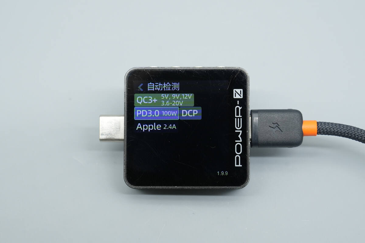
The USB-C2 cable supports QC3+, PD3.0, DCP, and Apple 2.4A charging protocols.
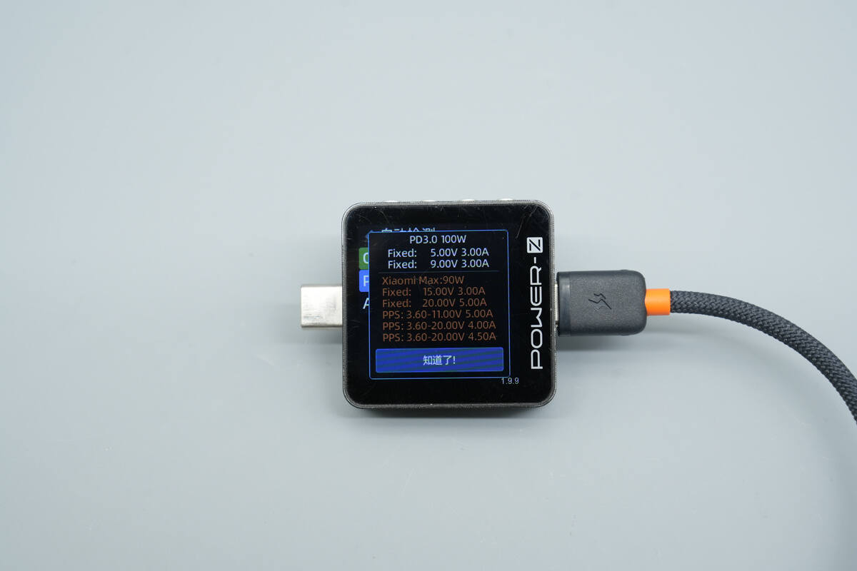
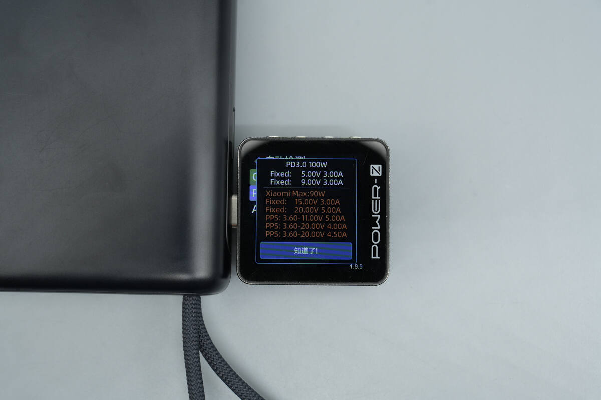
And it has four fixed PDOs of 5V3A, 9V3A, 15V3A, and 20V5A. It also supports Xiaomi’s 90W Surge fast charge, offering three voltage/current profiles: 3.6–11V 5A, 3.6–20V 4A, and 3.6–20V 4.5A.
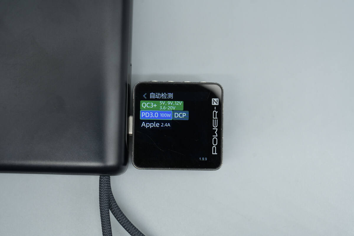
The USB-C port is compatible with the same protocols as the USB-C2 cable.
The PDO reports are the same as well.
The USB-A port supports QC3.0, FCP, SCP, AFC, DCP, and Apple 2.4A charging protocols.
Teardown
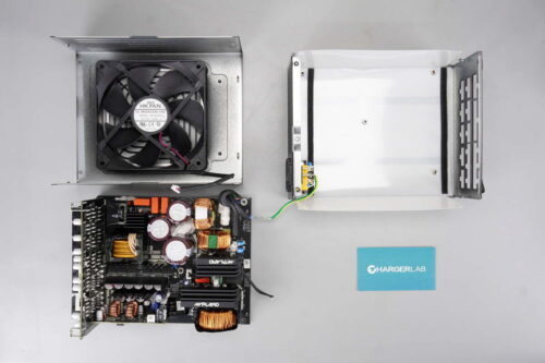
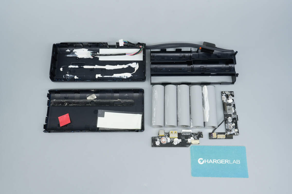
Next, let's take it apart to see its internal components and structure.

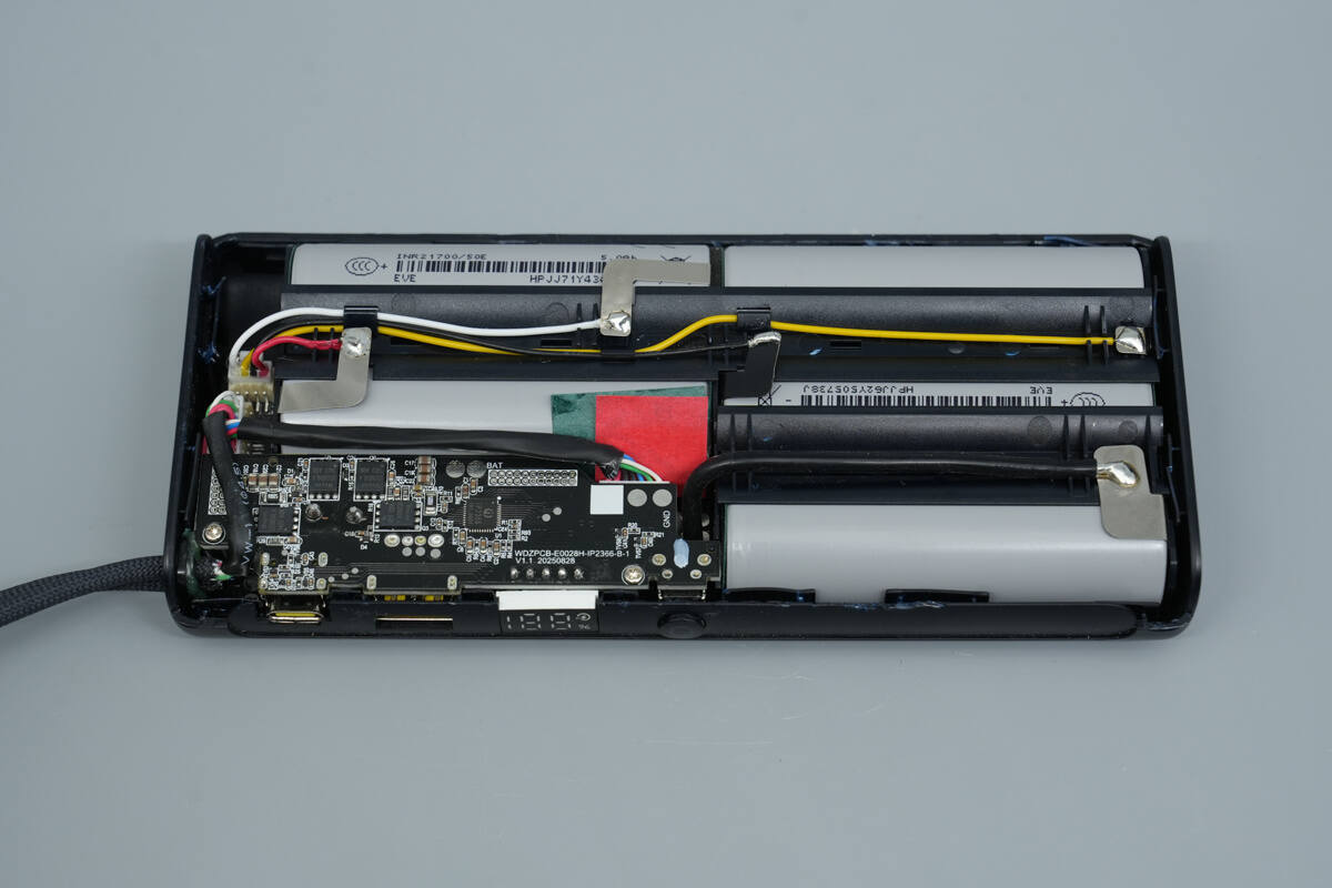
Open the casing, and the battery pack is found to be covered with Kapton insulating tape.
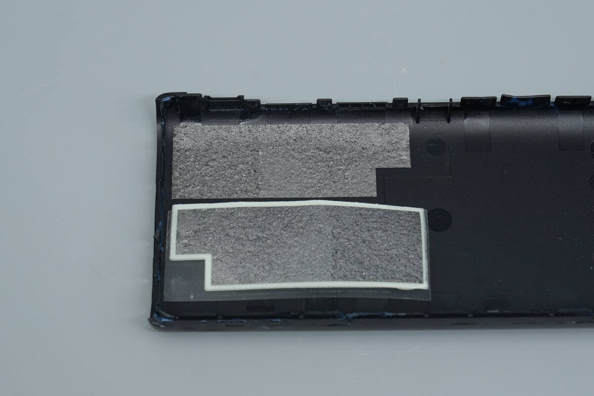
The casing is made of PC+ABS flame-retardant material, and the areas corresponding to the PCB on the inside are covered with graphite thermal pads.
After removing the insulating tape, it is revealed that the five battery cells are separated by plastic spacers.

One end of the wires is soldered to the nickel tabs of the battery cells.
The other end uses a plug-and-play connector, and both USB-C cables are also connected to the PCB via plug-and-play connectors.

The battery pack and PCBA module are removed. The inner side of the other half of the casing is coated with adhesive, and the area corresponding to the PCB is also covered with a thermal pad.
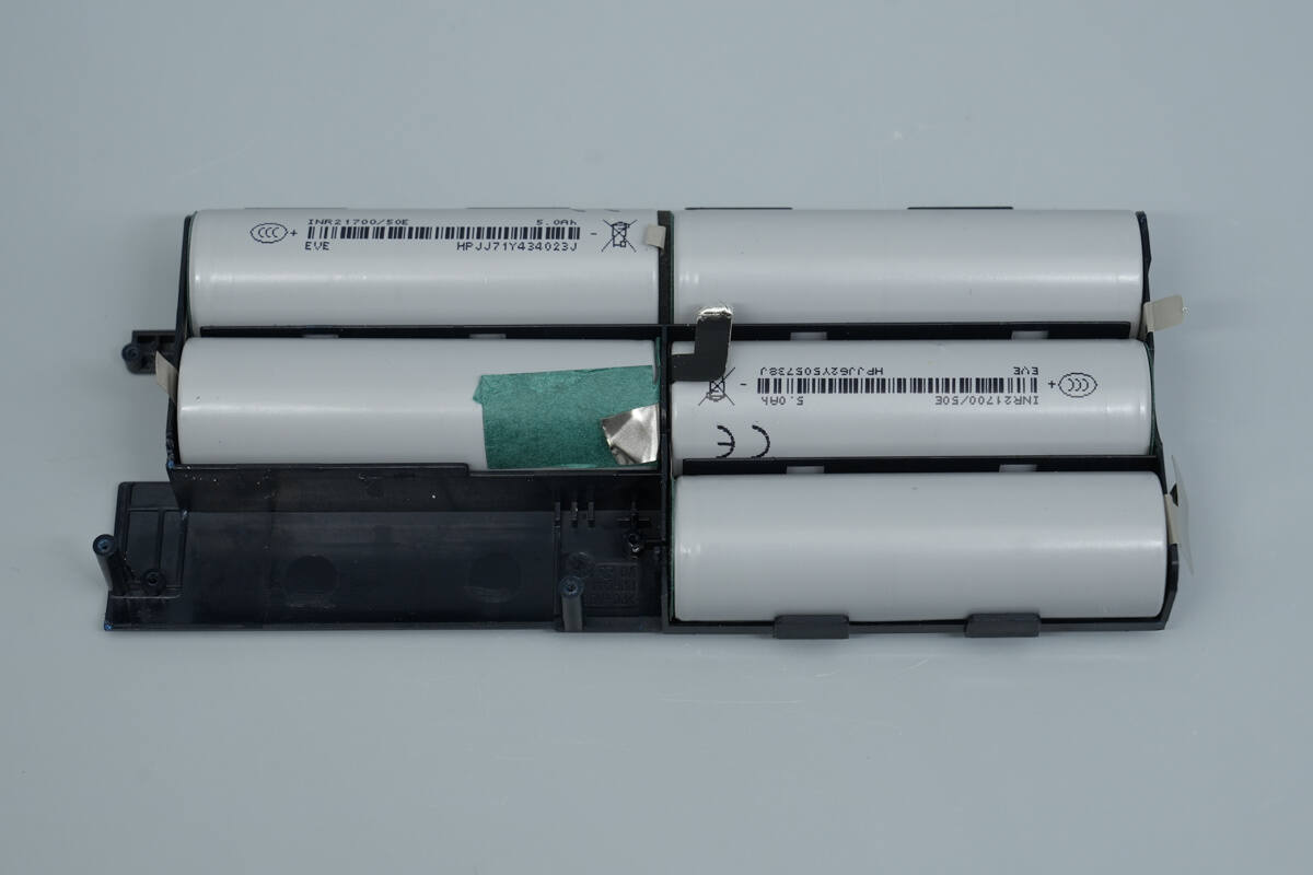
The five battery cells are placed within a plastic frame for support and secure positioning.
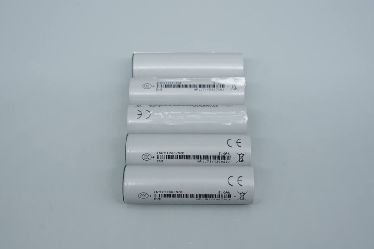
The five battery cells are separated, and all share the same part number.

The battery cells are sourced from EVE, model INR21700/50E. These are 21700 automotive-grade cells with a capacity of 5Ah and have passed CCC certification.
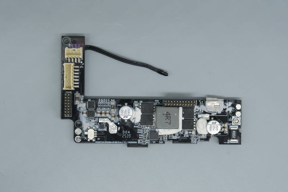
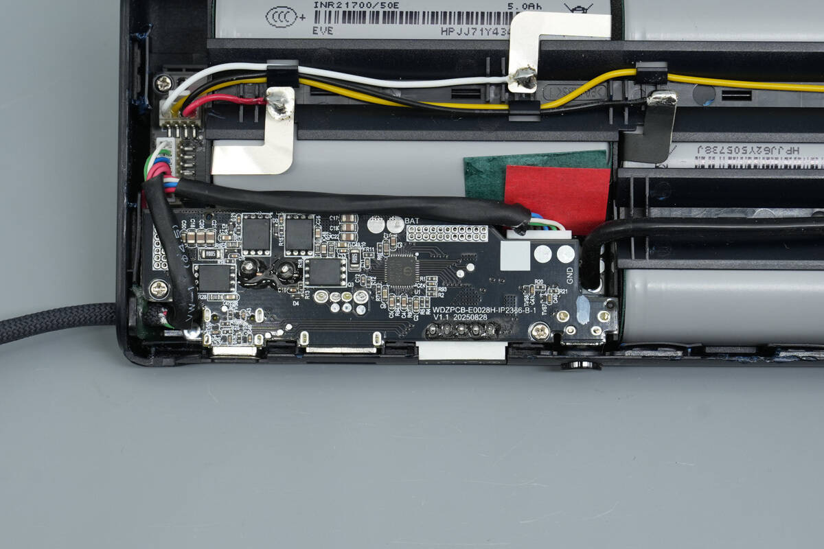
The PCBA module consists of two stacked PCBs. The bottom PCB connects to the USB-C1 cable, while the front side houses the VBUS MOSFETs, a synchronous buck-boost controller, synchronous buck-boost MOSFETs, a buck-boost inductor, and solid capacitors.

The back side contains a battery protection chip, battery protection MOSFETs, a linear voltage regulator, a protocol chip, a thermistor, and other components.

The battery protection chip is from iCM, model CM1351-CAT. This chip is specifically designed for 5-series lithium-ion or lithium iron phosphate batteries and features built-in high-precision voltage and current detection circuits. By monitoring the voltage of each cell, charging and discharging currents, and temperature, it provides protections including overcharge, overdischarge, cell balancing, disconnection, low-voltage charge inhibition, overcurrent during discharge, short circuit, overcurrent during charge, and overtemperature. The discharge overcurrent protection delay is adjustable via an external capacitor, while other protection delays are internal. The chip also has a built-in cell balancing function.

The iCM CM1351 offers 15 mV accuracy for overcharge protection, supports three-level discharge overcurrent protection, and provides overcurrent protection during charging. It also supports individual cell disconnection protection and NTC thermistor disconnection protection, delivering comprehensive protection for multi-series lithium battery packs.

The four battery protection MOSFETs are marked “7408” and use a DFN 5×6 package.
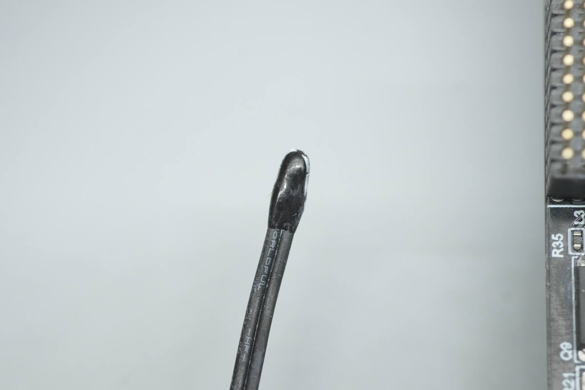
Close-up of the thermistor.
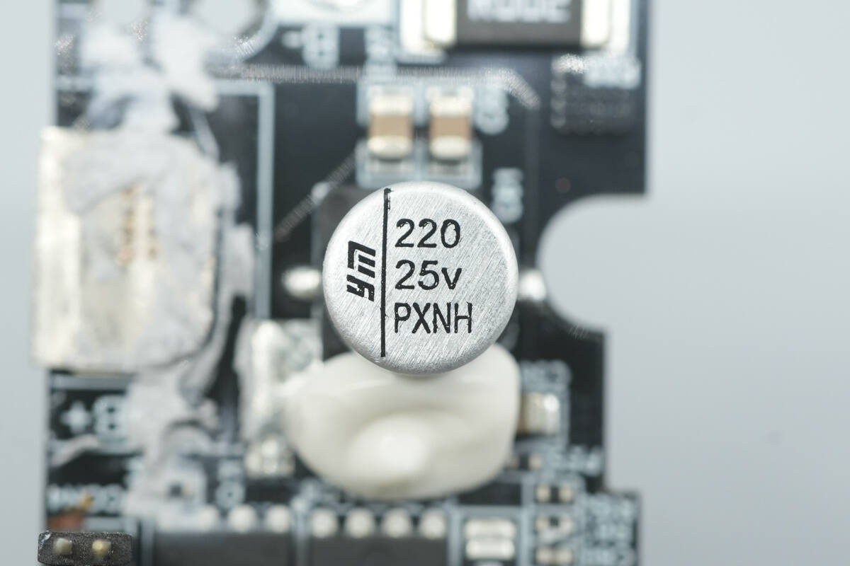
The solid capacitor is from YMIN, with a specification of 25V 220 μF.
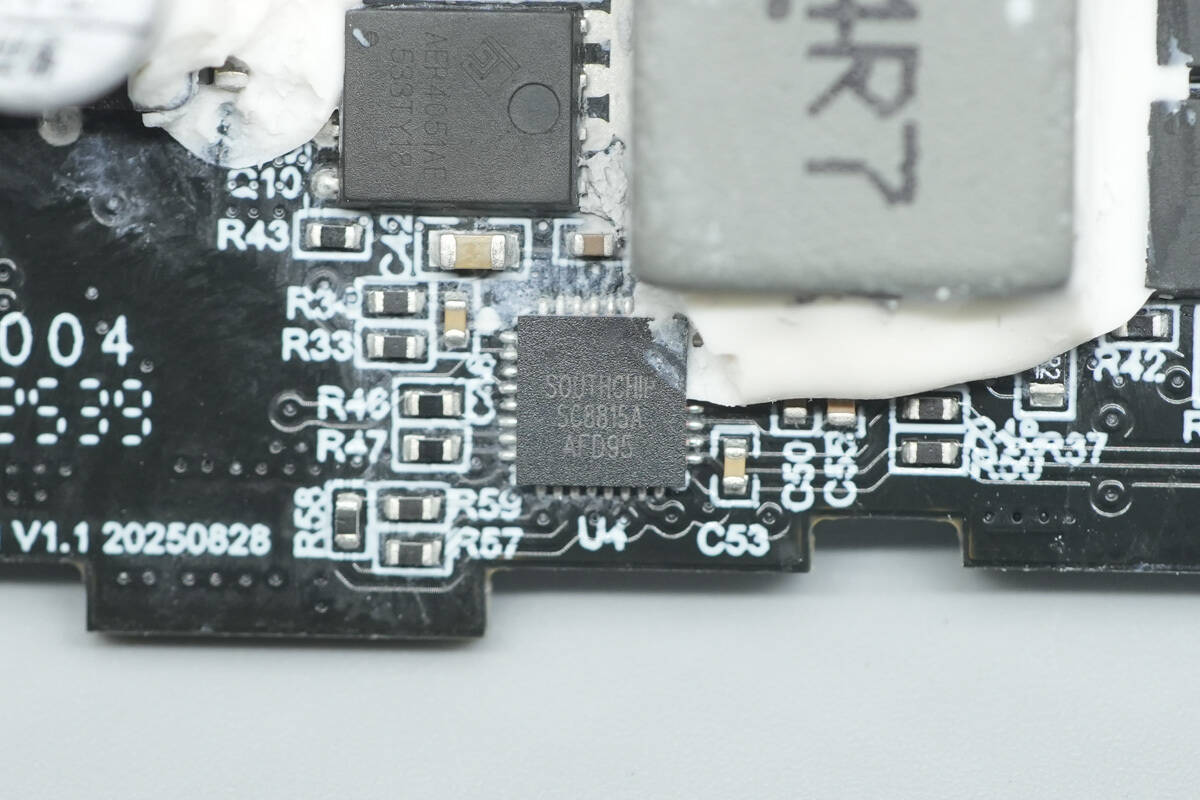
The synchronous buck-boost controller is from SouthChip, model SC8815A. It supports charging 1–6 series batteries and operates at up to 36 V. The chip provides complete lithium battery charging management, with battery charging current and voltage, reverse discharge output voltage, and input/output current limits all controllable via the I²C bus.
The SC8815A features a built-in 10-bit ADC, charging status indicators, automatic adapter and load insertion detection, undervoltage protection, overvoltage protection, overcurrent protection, as well as short-circuit and overtemperature shutdown protection. It comes in a QFN32 package and is suitable for PD fast-charging power banks, USB-C hubs, and industrial power applications.

Here is the information about SouthChip SC8815A.
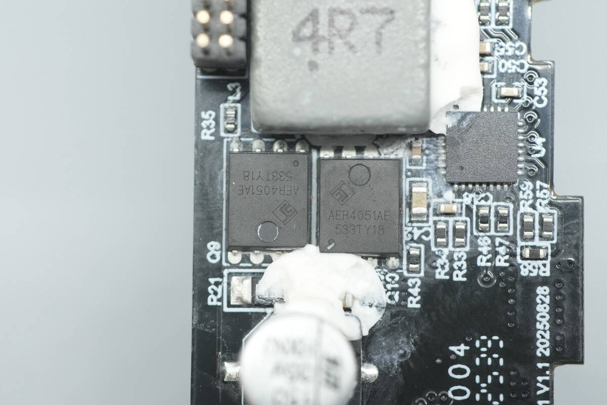
The four synchronous buck-boost MOSFETs are from ALLEPIC, model AER4051AE. They are NMOS transistors with a voltage rating of 40 V, an on-resistance of 5.5 mΩ, and come in a PDFN 5×6 mm package.

Close-up of the two MOSFETs on the other side.

The 4.7 μH buck-boost inductor is secured with adhesive for reinforcement and protection.

The solid capacitor is from YMIN, with a specification of 35 V 150 μF.

The linear voltage regulator is model 7333-1 and comes in an SOT-89 package.
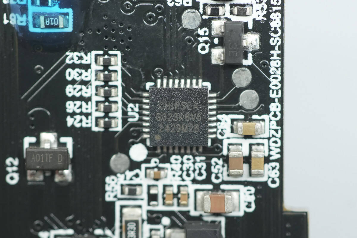
The protocol chip is from Chipsea, model CS32G023K8V6. It supports PD3.1 fast charging and PPS, as well as QC4.0+, Huawei SCP, FCP, Samsung AFC fast charging protocols, and VOOV fast charging. The chip integrates an ARM Cortex-M0 core running at up to 48 MHz, and includes 64 KB of Flash and 8 KB of SRAM.
The CS32G023 supports multiple operating modes and various low-power strategies. It's built-in Flash features multi-level security, and the internal SRAM supports parity checking. The chip comes in a QFN32 package and is suitable for applications such as power banks, USB-C hubs, and monitors.

Here is the information about Chipsea CS32G023K8V6.
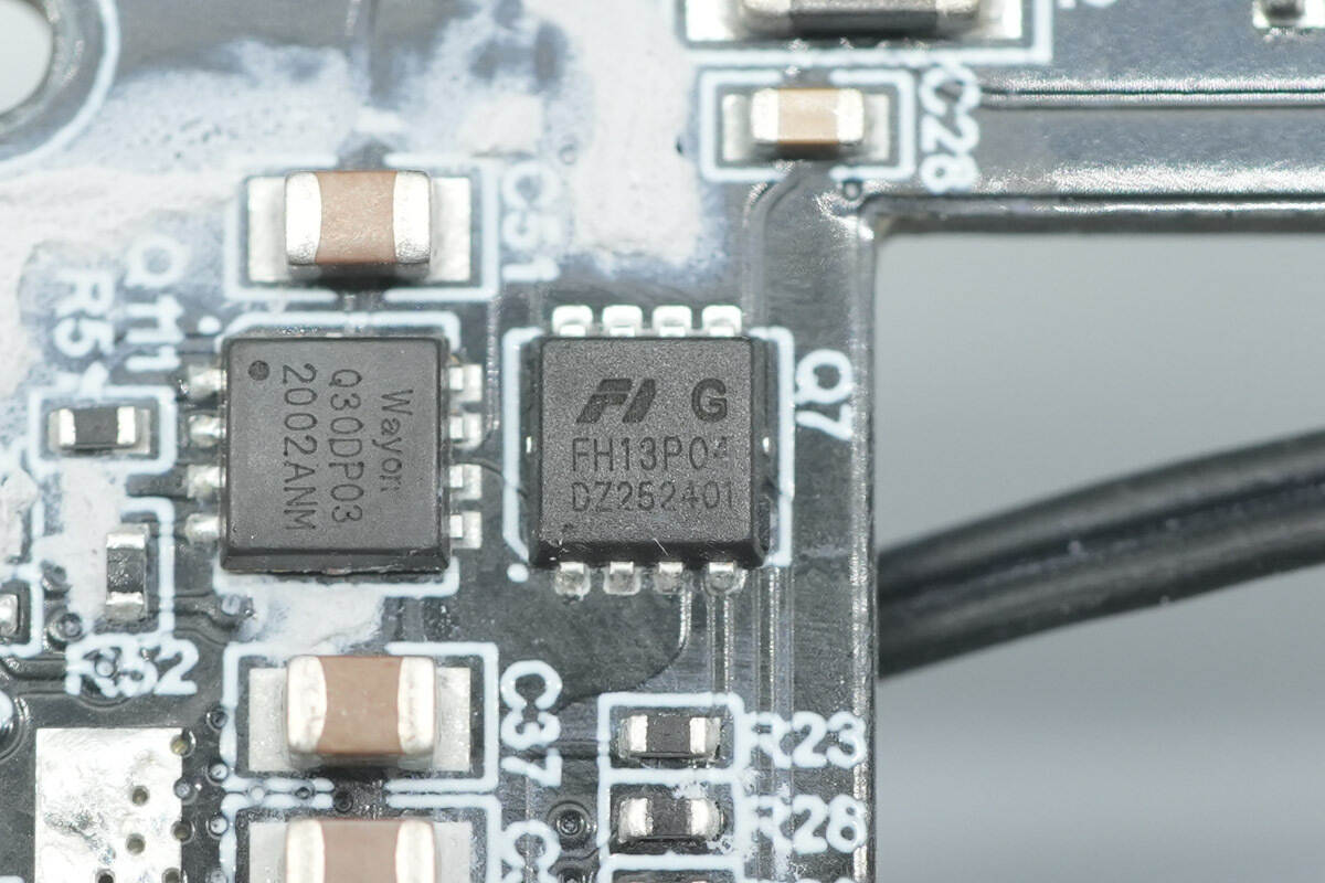
The VBUS MOSFET is from Xinfeihong, model FH13P04G6. It is a PMOS transistor with a voltage rating of –40 V, an on-resistance of 9 mΩ, and comes in a PDFN 3.3×3.3 mm, 8-lead package.
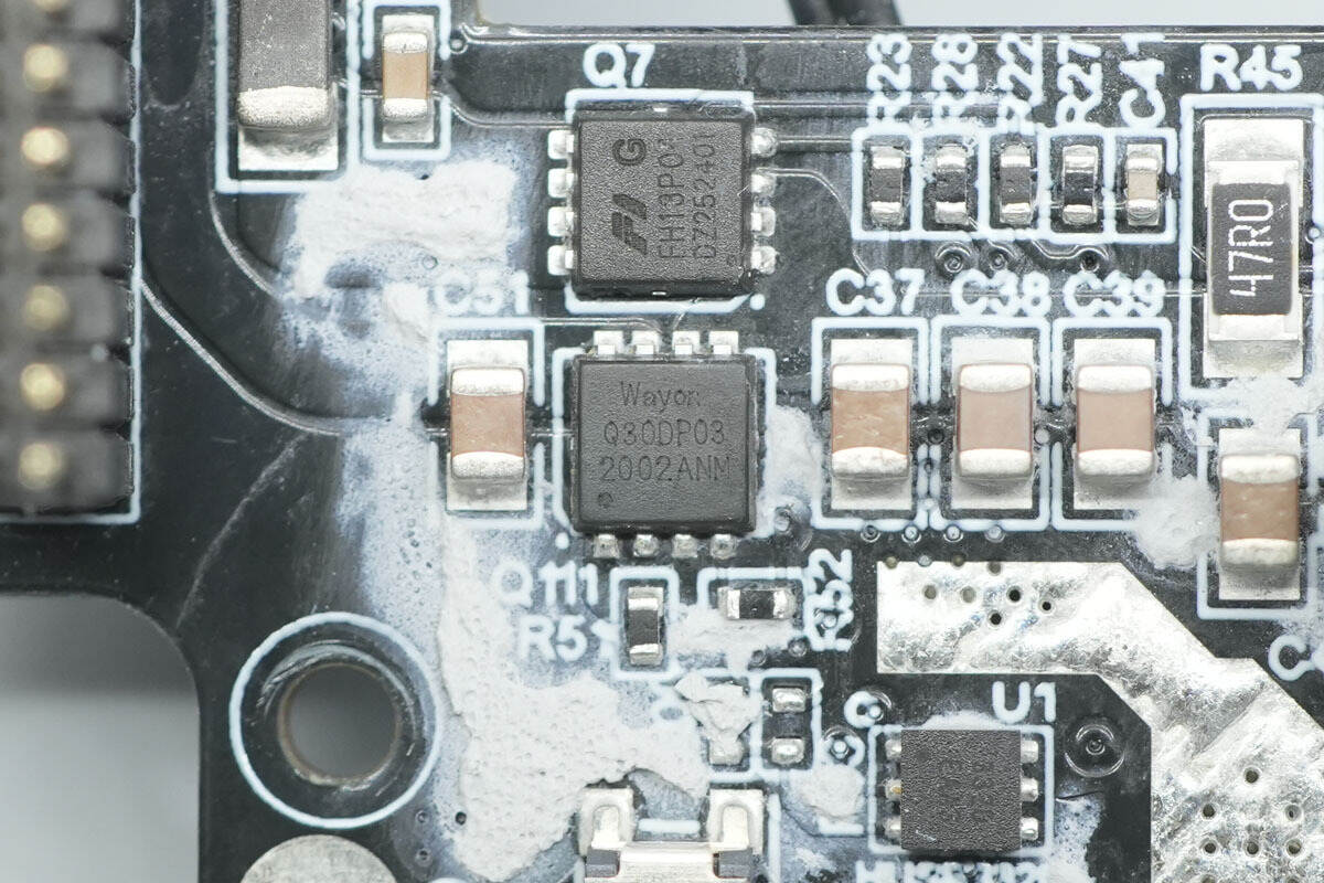
The other VBUS MOSFET is from Wayon, model WMQ30DP03TS. It is a dual PMOS with a voltage rating of –30 V, low on-resistance, and comes in a PDFN 3×3 mm, 8-lead package.

The E-Marker chip, marked “332D,” is model HUSB332D from Hynetek. It is a newly released USB E-Marker that supports the USB Type-C 2.2 specification, USB Power Delivery 3.1, USB 4.2, and Thunderbolt 3 and 4 standards. It also supports the USB PD 3.1 Extended Power Range (EPR). The HUSB332D has been certified by the USB-IF, with TID number 9125.
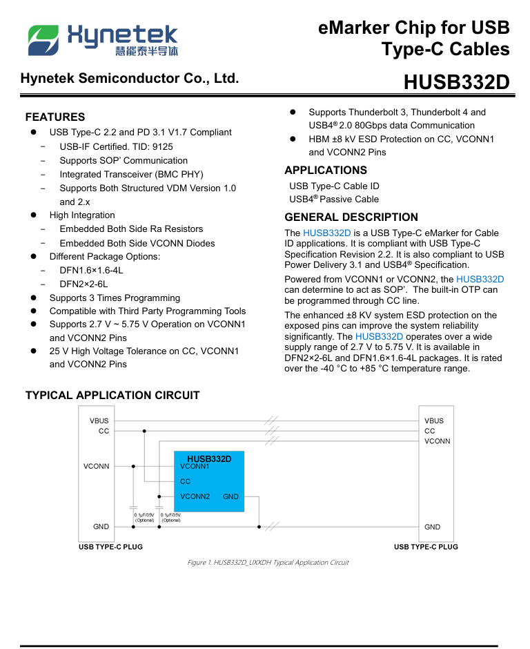
Here is the information about Hynetek HUSB332D.
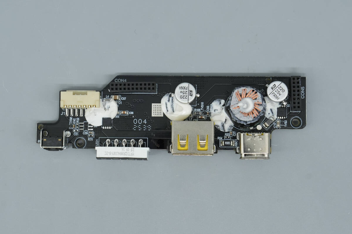
The top PCB connects to the USB-C2 cable. Its front side is equipped with a buck-boost inductor, solid capacitors, VBUS MOSFETs, and other components.
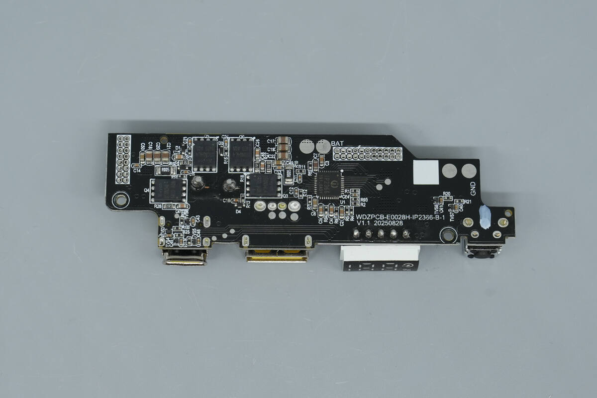
The back side houses a power management chip and synchronous buck-boost MOSFETs.

The power management chip for the USB-C2 cable and USB-C port is from Injoinic, model IP2366. This is a lithium battery charge-discharge management chip that integrates multiple fast-charging protocols, including PD3.1, and a bidirectional synchronous buck-boost converter, supporting up to 140 W charging and discharging power.
The chip features high integration and rich functionality, requiring only a single inductor to achieve synchronous buck-boost operation. It needs minimal external components in applications, effectively reducing overall solution size and lowering BOM costs.

The IP2366 supports 2, 3, 4, 5, or 6 series battery cells, with the number of series and battery type selectable via external resistors. Fully charged voltage can be set to 3.65 V, 4.1 V, 4.2 V, 4.35 V, or 4.4 V. It has built-in monitoring loops for chip temperature, battery temperature, and input voltage, allowing it to intelligently adjust the charging current based on the detected charger power.
The IP2366 supports a low-power mode, reducing standby current to 5 μA. Inserting a charger automatically wakes the chip for charging, while discharging requires a short press of the power button to wake it. The chip features a built-in 14-bit ADC for precise measurement of input voltage/current, battery voltage/current, and other parameters. Charge and discharge data can be accessed via the I²C interface.
It comes in a 5×5 mm, 0.4 mm pitch QFN40 package and provides multiple protections, including input overvoltage and undervoltage, output overcurrent and short-circuit, battery overcharge, overdischarge, overcurrent, chip overtemperature, and NTC-based battery temperature protection, ensuring high reliability. The CC1 and CC2 pins support up to 30 V, effectively preventing damage to the device.

The four synchronous buck-boost MOSFETs are from Wayon, marked “050N04L4,” with model number WMQ050N04LG2. They are NMOS transistors rated for 40 V, with an on-resistance of 5 mΩ, and come in a PDFN 3×3 mm, 8-lead package.
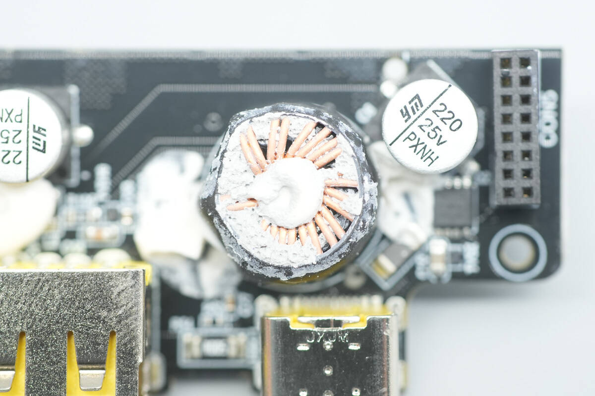
The buck-boost inductor is insulated and protected with a heat-shrink tubing sleeve.
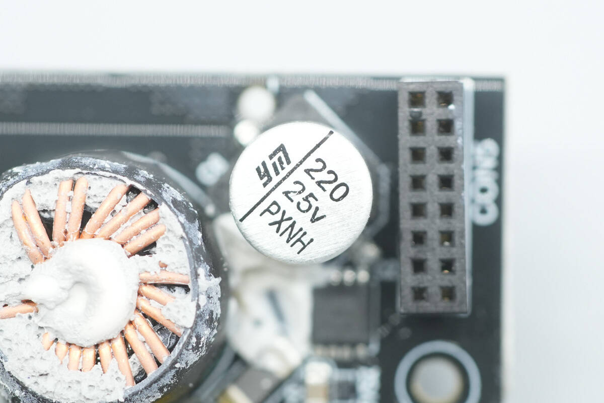
The solid capacitor is from YMIN, with a specification of 25 V 220 μF.
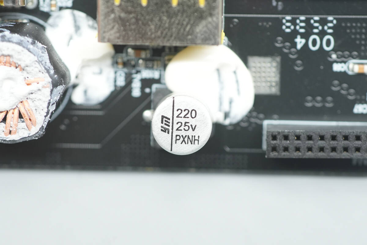
The other solid capacitor has the same part number and specification.

The VBUS MOSFET is from Wayon, marked “070N04L4,” with model number WMQ070N04LG4. It is an NMOS transistor rated for 40 V, with an on-resistance of 6.2 mΩ, and comes in a PDFN 3×3 mm, 8-lead package.

Close-up of the other Wayon WMQ070N04LG4 VBUS MOSFET.
Well, those are all components of the Baseus 145W 25000mAh Power Bank.
Summary of ChargerLAB

Here is the component list of the Baseus 145W 25000mAh Power Bank for your convenience.
The battery pack is composed of five EVE 21700 automotive-grade cells, with a total energy of 91.25 Wh, meeting airline carry-on standards. Plastic spacers are placed between the cells to enhance safety and stability. The pack uses an iCM CM1351 5-series protection chip, combined with thermistors and multiple MOSFETs, to ensure safe responses under conditions such as overcharge, overdischarge, overcurrent, and short circuit.
After taking it apart, we found that it uses a SouthChip SC8815A buck-boost controller and a Chipsea CS32G023 protocol chip, supporting multiple fast-charging protocols including PD3.1 and PPS. The USB-C2 cable and USB-C port are independently managed by the Injoinic IP2366.
Overall, the product demonstrates a high level of maturity in terms of materials, craftsmanship, and design choices. It not only supports high-performance 140 W PD3.1 output but also is compatible with Xiaomi’s 90 W Surge fast charge. This combination meets users’ demands for high-performance fast charging and large capacity while maintaining portability and practical everyday usability.
Related Articles:
1. Teardown of 3Y POWER 1600W SiC Server Power Supply (YSEF1600EM)
2. Teardown of BULL 67W GaN Digital Display Power Strip (GNV-ML1676)
3. Teardown of KOAKUMA 3-in-1 Display Qi2.2 Wireless Charger