Introduction
Compared to traditional electric vehicles, new electric vehicles utilizing an 800V platform instead of the conventional 400V platform not only reduce conductor cross-sectional area and vehicle weight but also enable higher drive and charging power, significantly shortening charging time. We have obtained the UUGreenPower 20kW charging module UR100020-SW, which supports an output voltage of up to 1000V, making it suitable for fast charging of 800V platform electric vehicles.
The UUGreenPower UR100020-SW charging module supports a 380V AC input and features an ultra-wide output voltage range, making it compatible with electric vehicles across different voltage platforms. It includes multiple protection functions such as input/output overvoltage and undervoltage, overcurrent, and short-circuit protection. The module is controlled by a DSP and is equipped with an LED display for information readout, as well as a CAN communication interface. Below, we present its teardown to take a closer look at the internal design and components.
Product Appearance
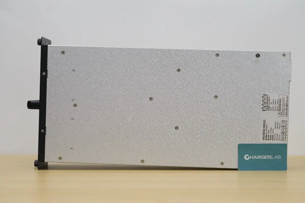
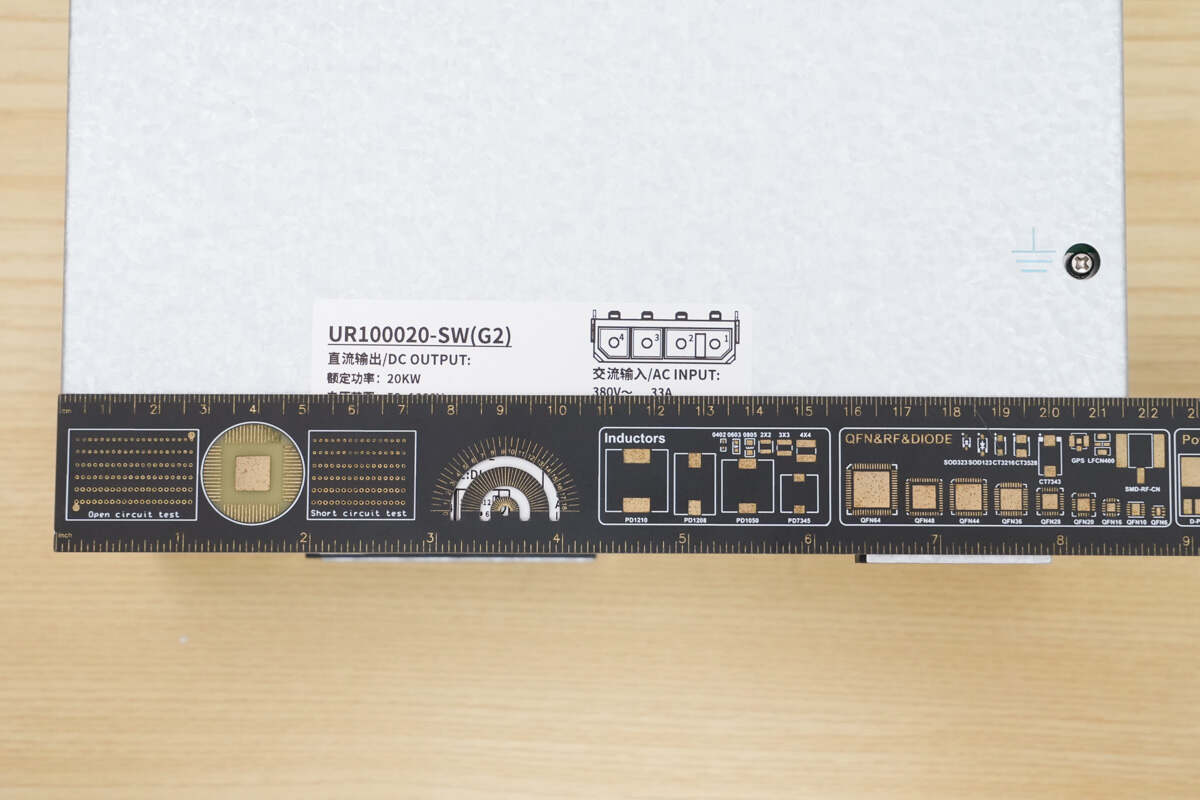
The charging module features a metal enclosure with an information label affixed to the rear.
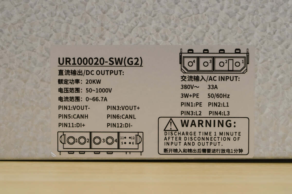
AC Input:
380V~ 33A 50/60Hz
DC Output:
Rated Power: 20kW
Voltage Range: 50–1000V
Current Range: 0–66.7A
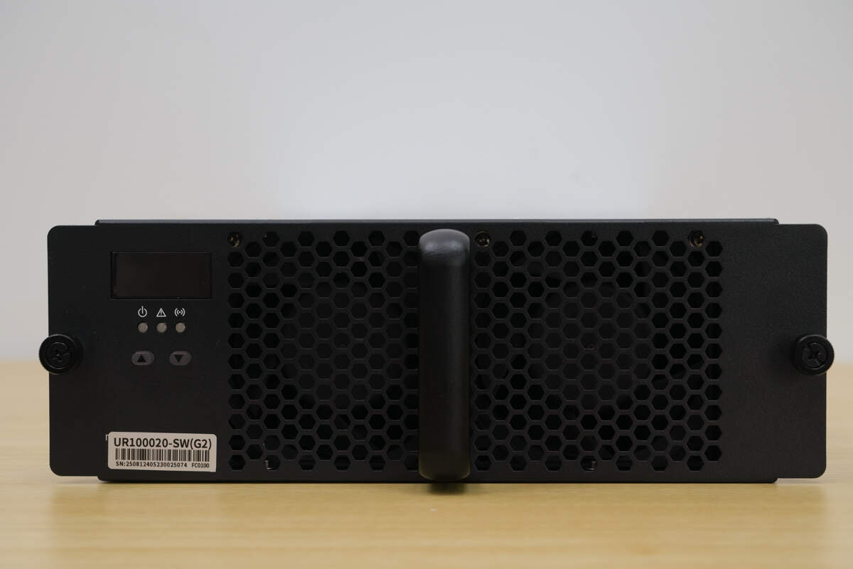
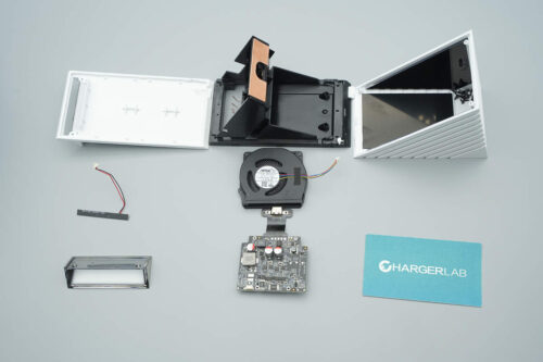
The front panel has mounting screws on both sides. On the left side, there is an LED display, indicator lights, and buttons. The center features a handle and cooling fans.
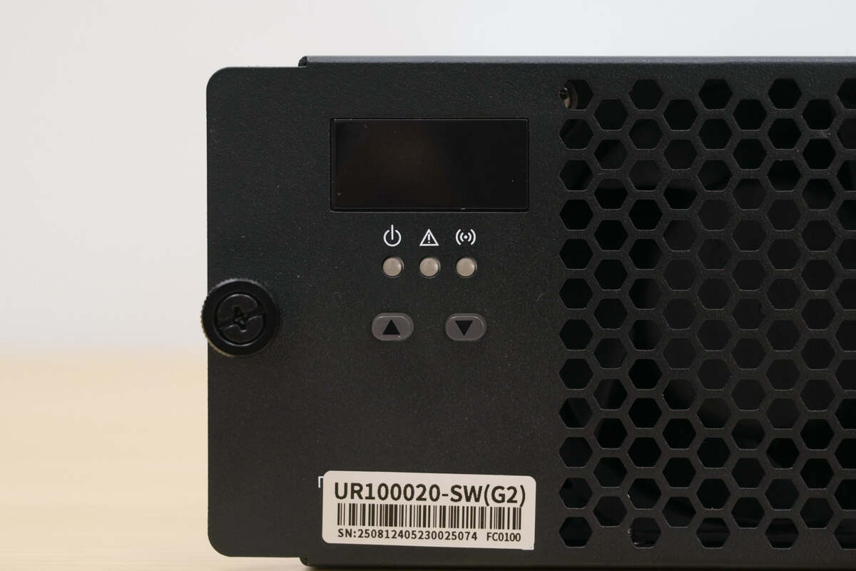
Close-up of the LED display, indicator lights, and buttons.
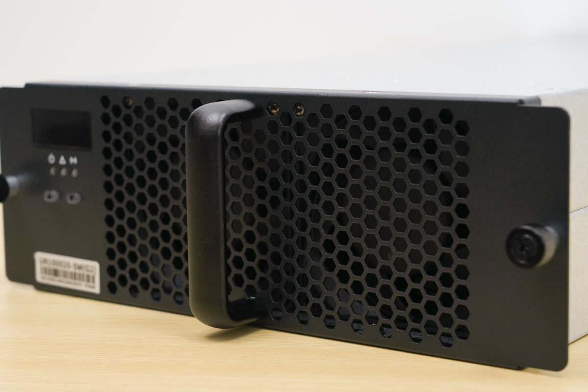
The handle assists with module installation.
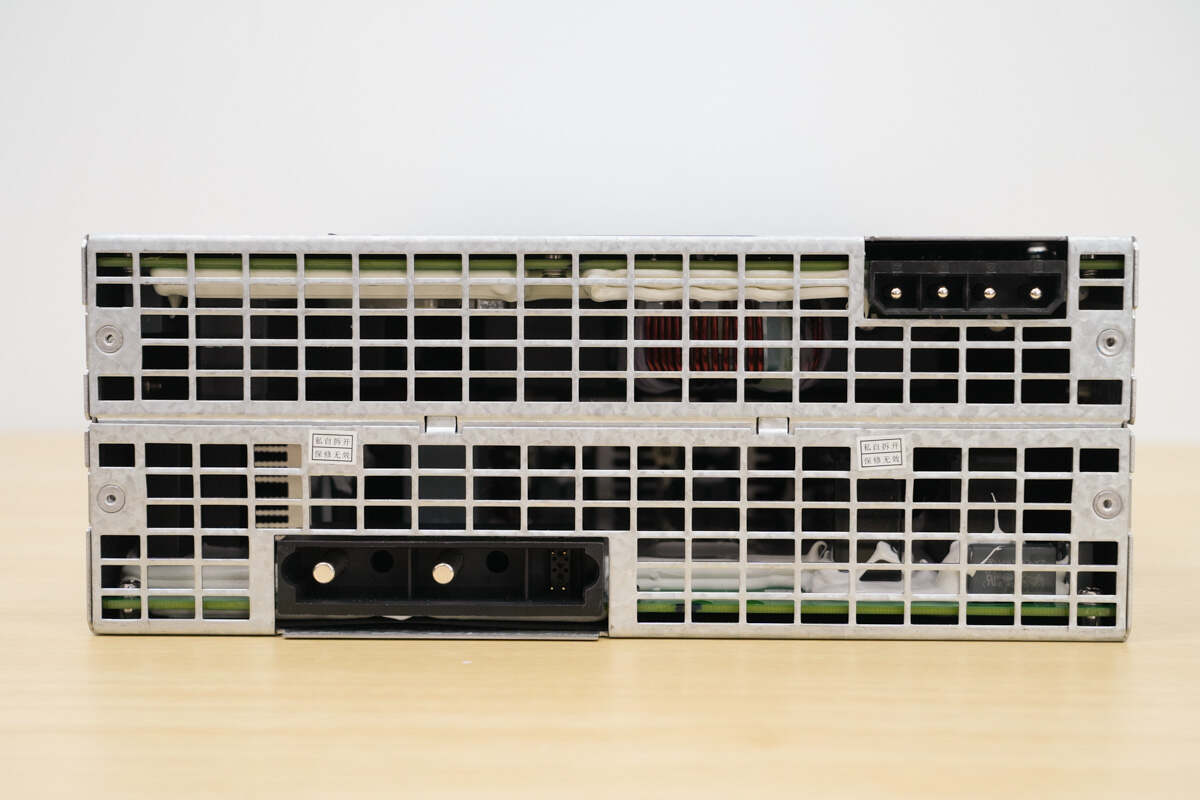
The rear of the module features the AC input connector and the DC output connector.
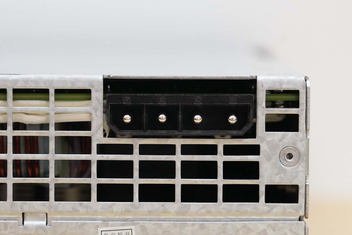
The AC input connector features a four-pin design with reverse polarity protection.
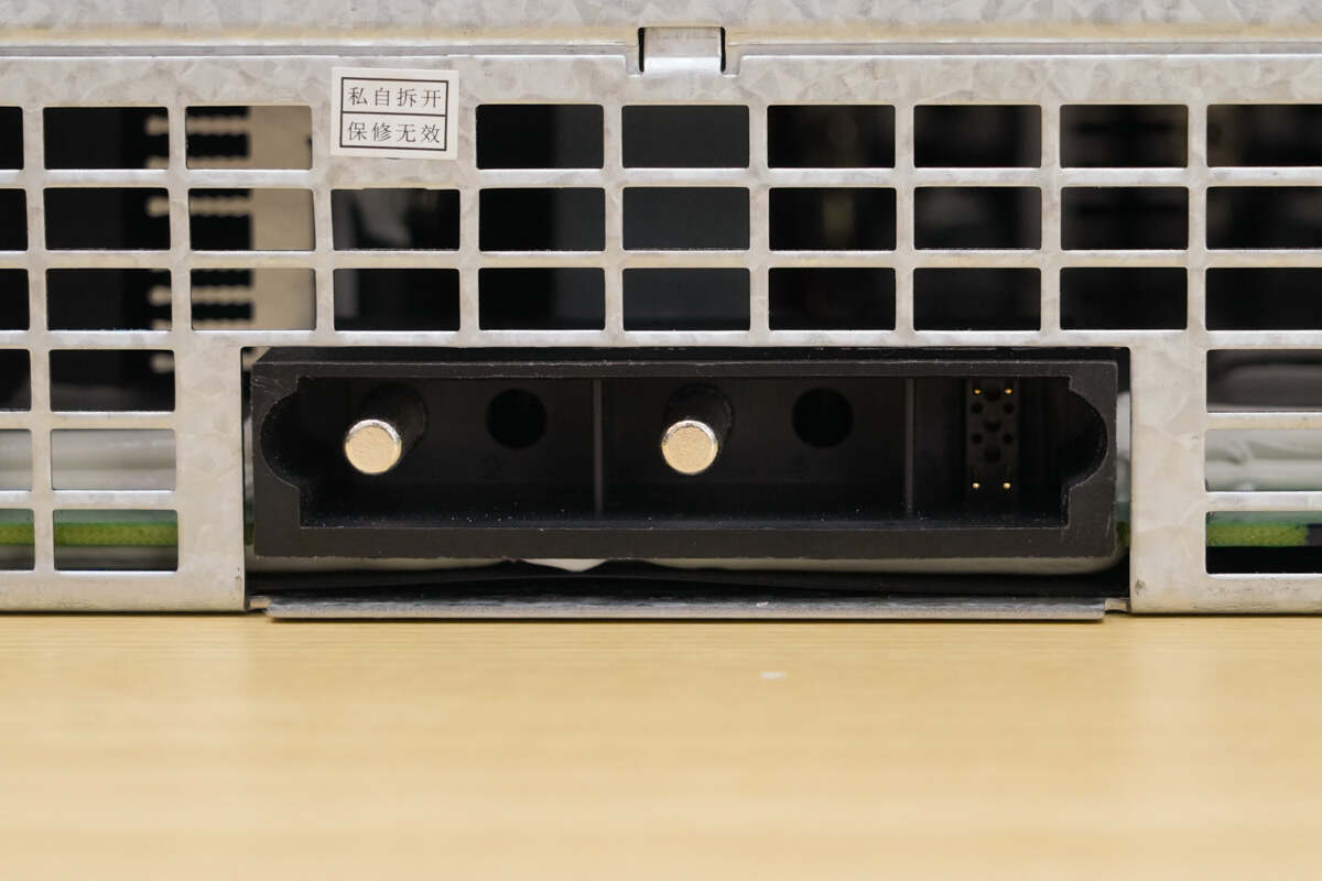
Close-up of the DC output connector and the CAN communication interface.
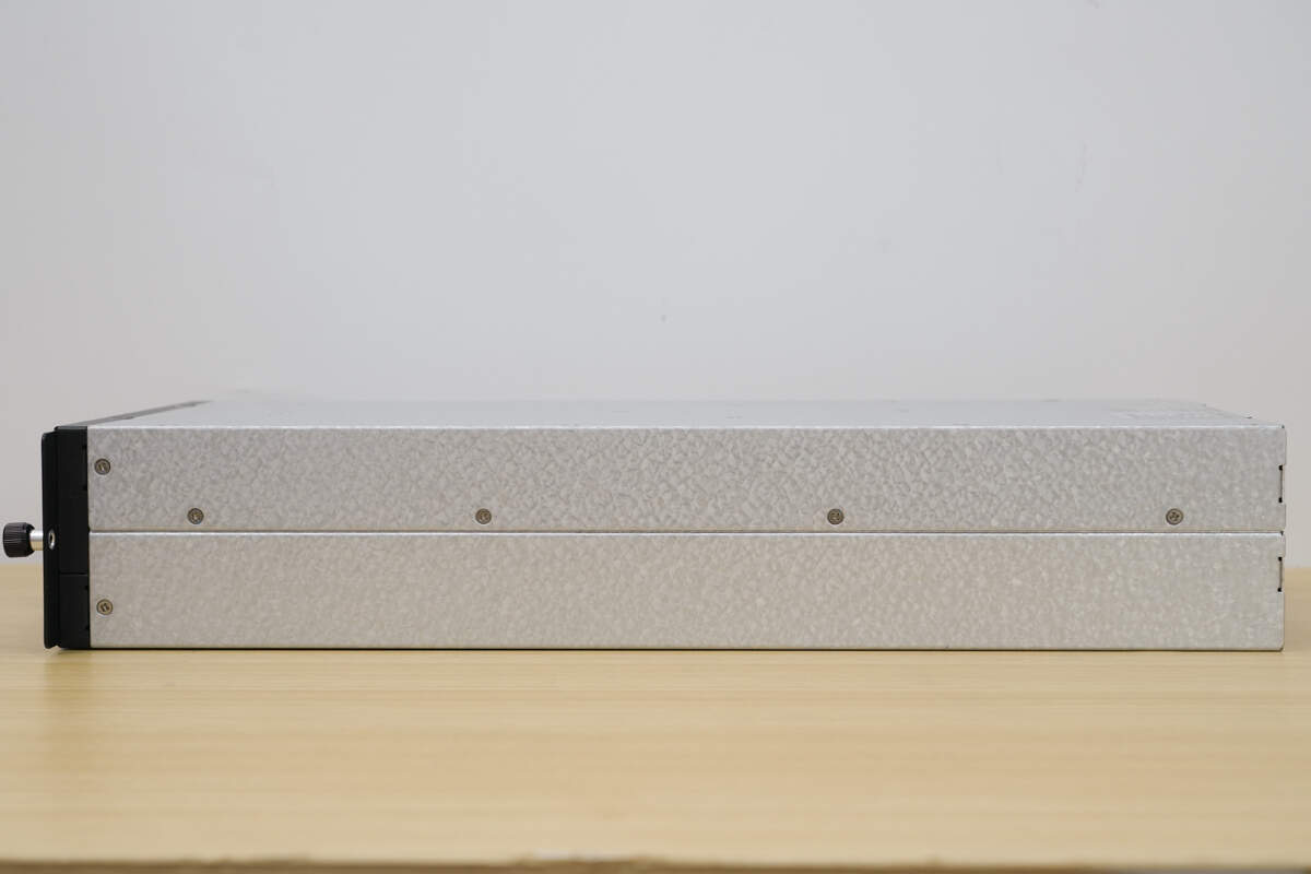
The sides are secured with screws.
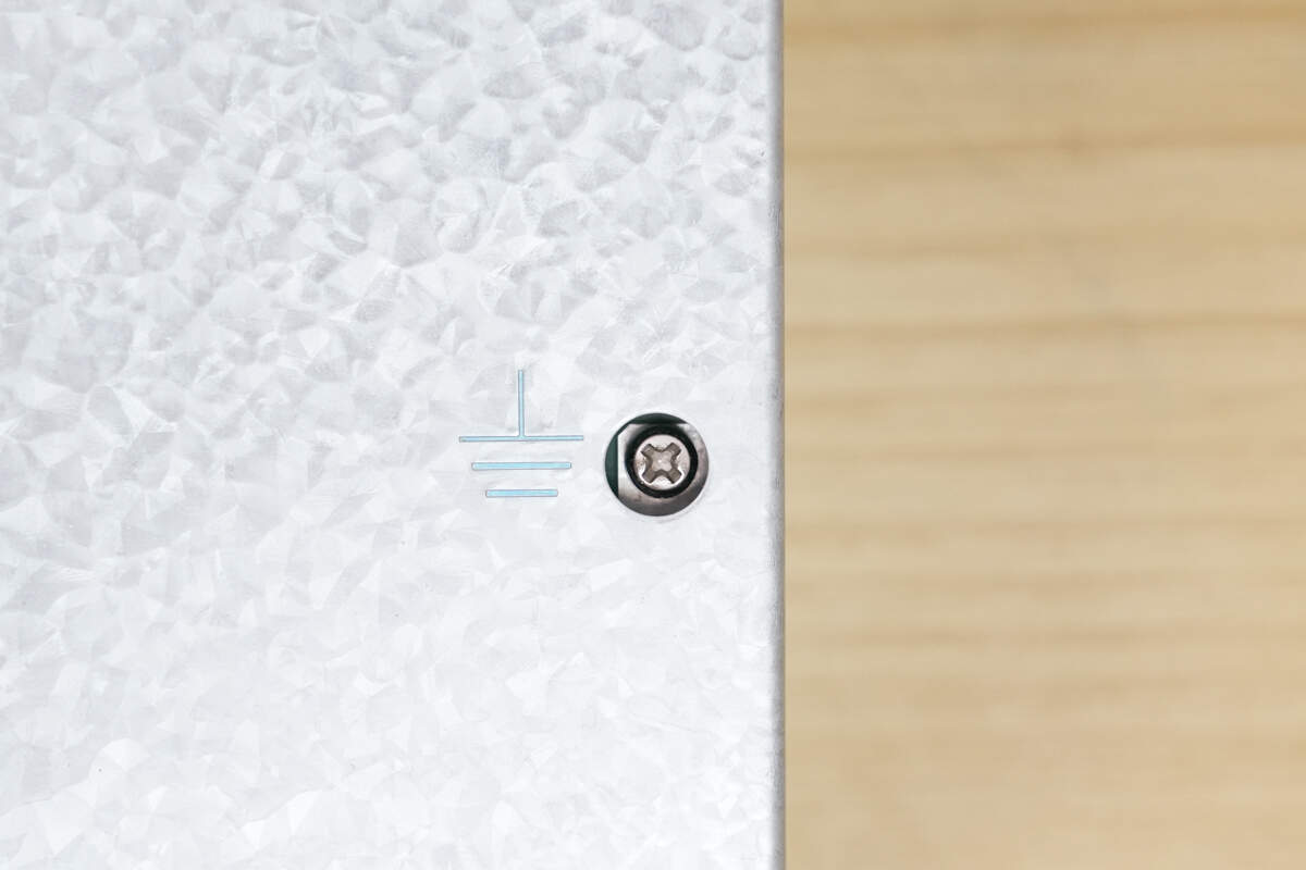
A grounding screw is located on the front panel.
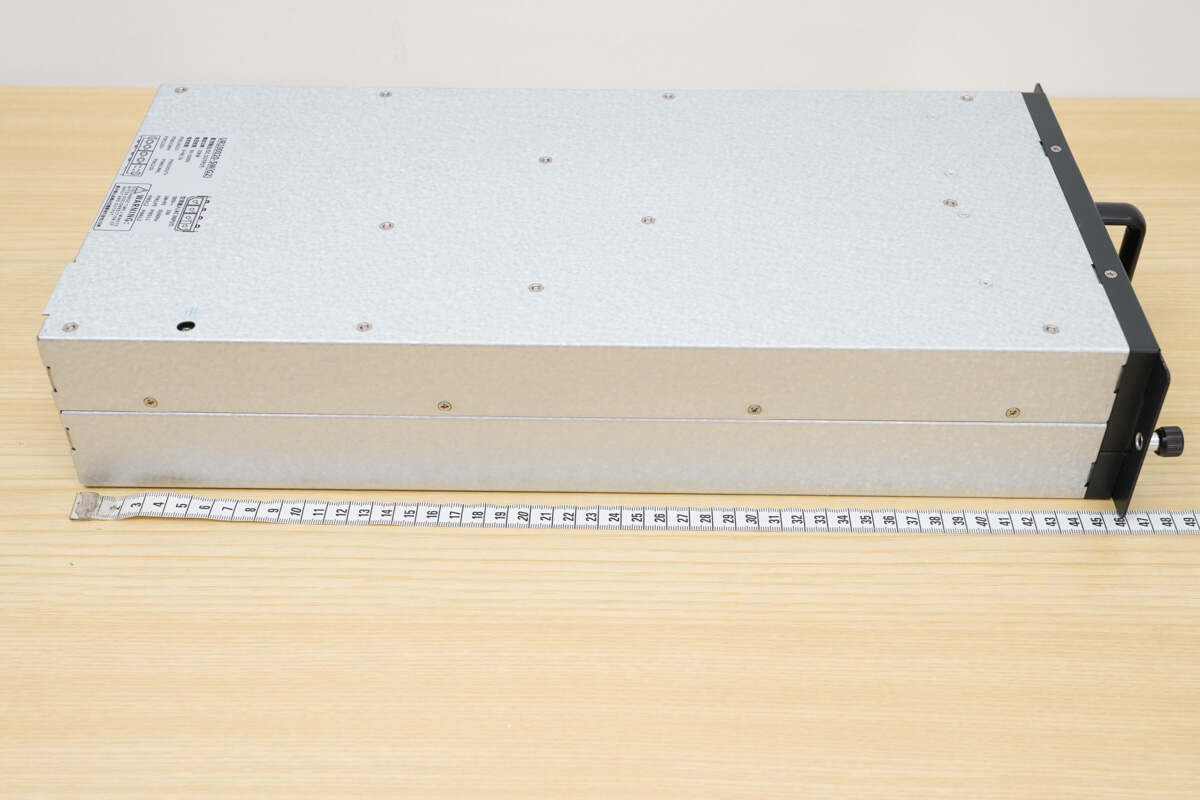
The length is about 480 mm (18.9 inches).
The width is about 217 mm (8.54 inches).
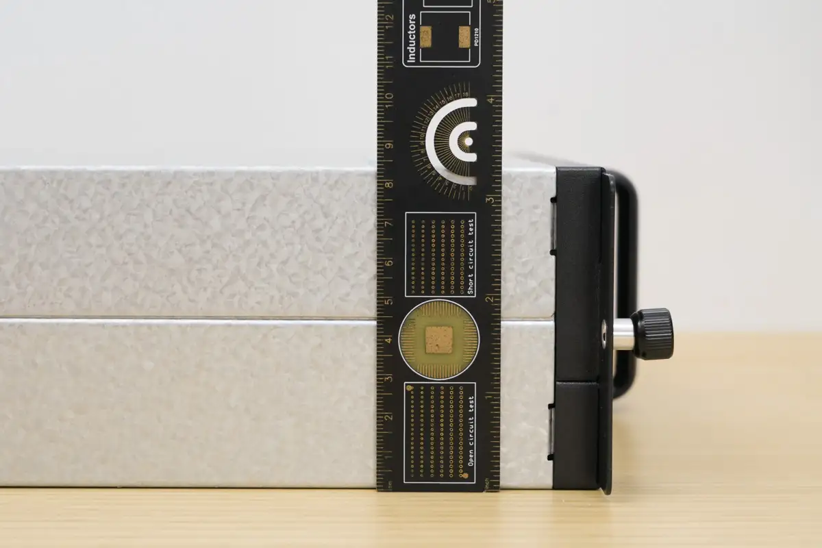
The thickness is about 83 mm (3.27 inches).
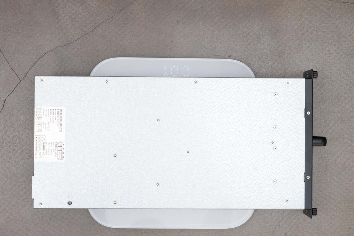
The weight is about 10.3 kg (22.71 pounds).
Teardown
Next, let's take it apart to see its internal components and structure.
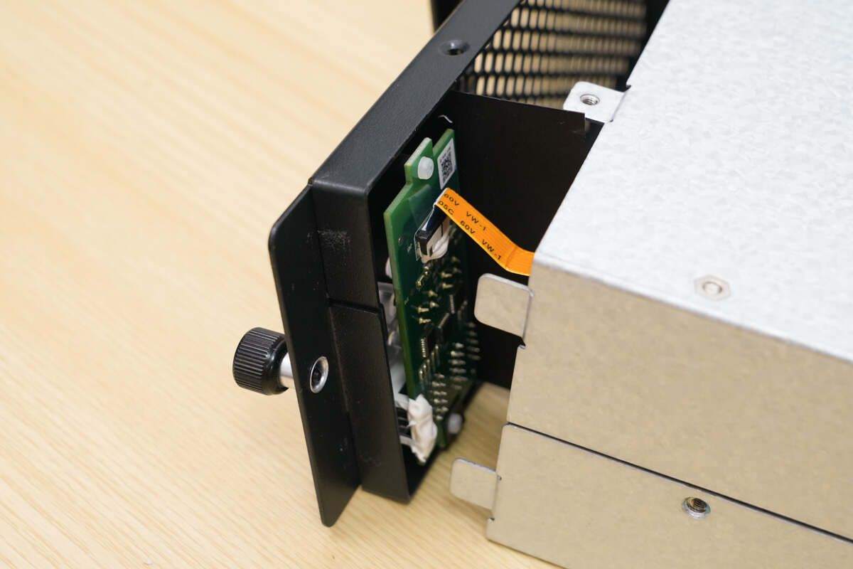
Remove the mounting screws on the module’s front panel. The small PCB is connected via a ribbon cable.
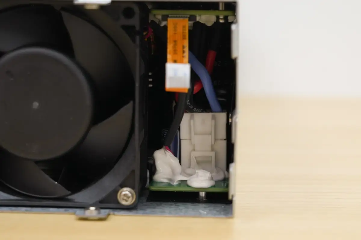
Inside, there is a connector installed.
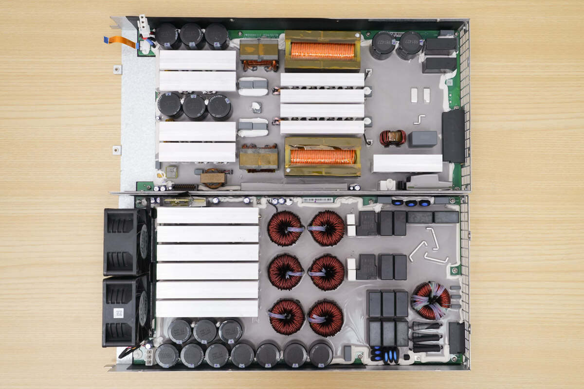
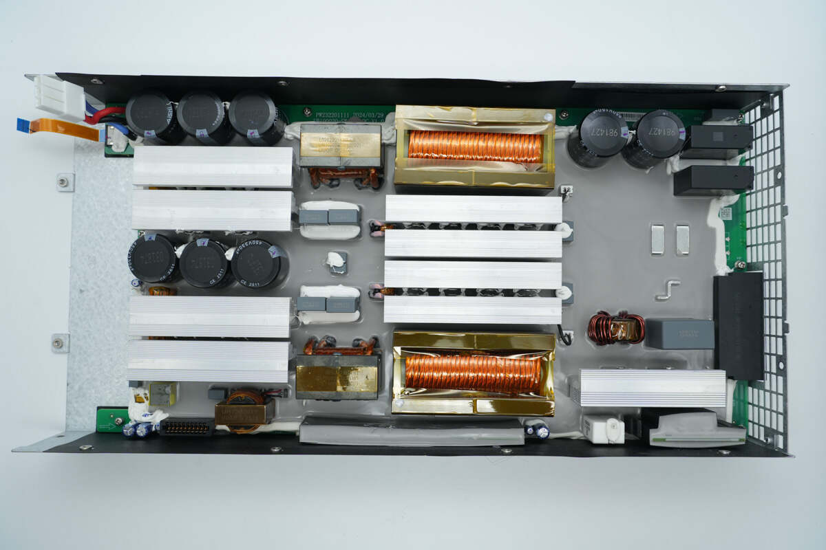
Unscrew the mounting screws and open the enclosure. The upper section houses the LLC module, while the lower section contains the PFC module.
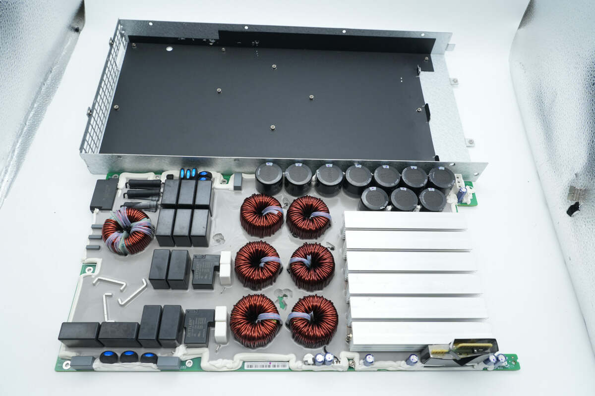
Remove the PFC module.
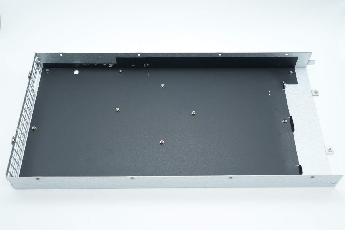
The inside of the enclosure is lined with a Mylar insulation sheet.
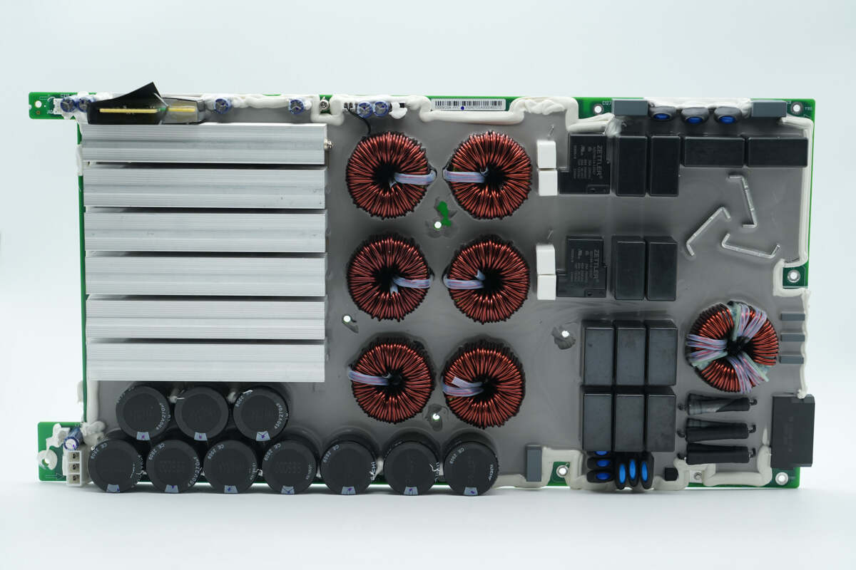
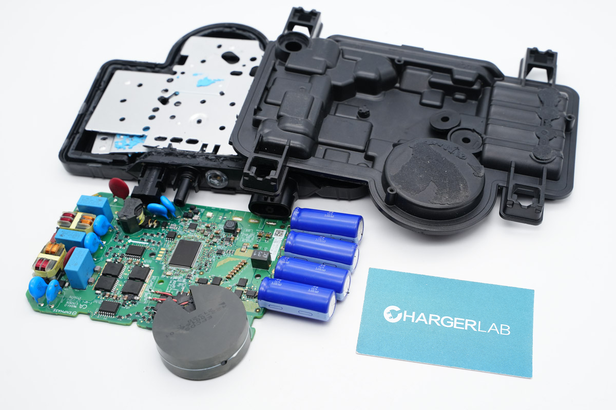
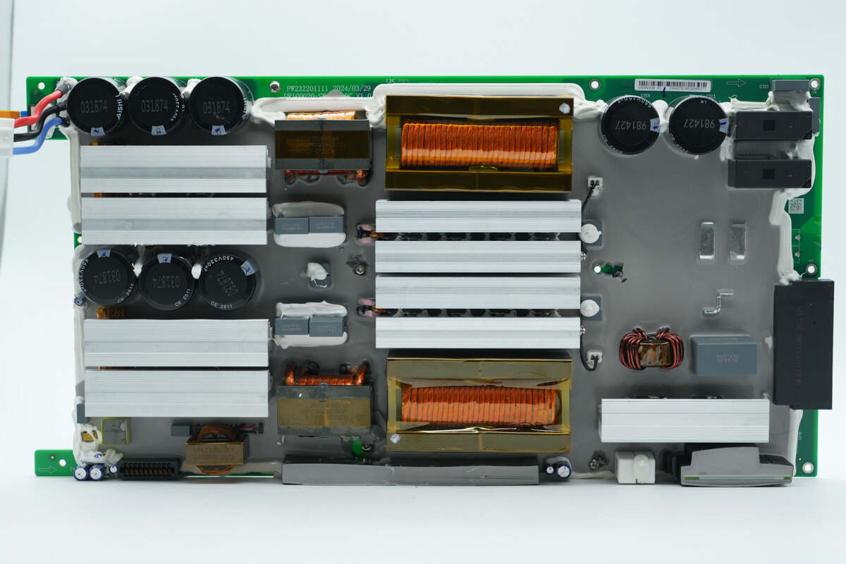
The PCBA module uses potting technology for sealing and moisture resistance, enhancing reliability.
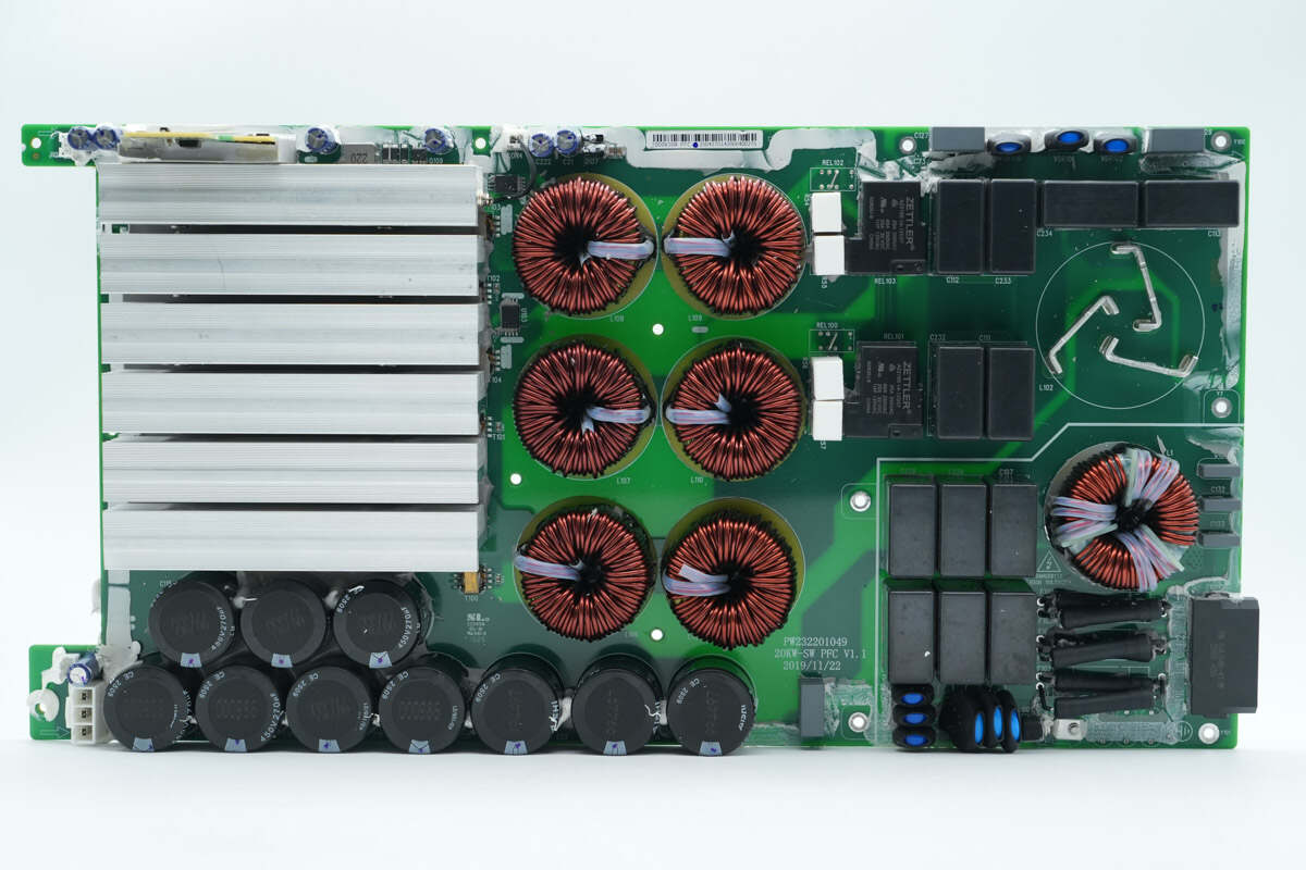
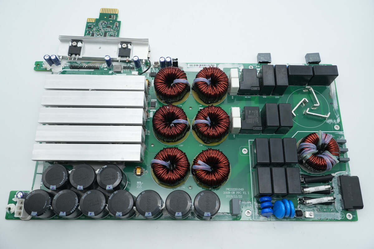
The lower right corner is the AC input section, equipped with a connector, fuses, varistors, a gas discharge tube, safety X2 capacitors, a common mode choke, and film Y capacitors. Above, on the right side, is a relay and startup resistors. The center area houses the PFC boost inductors.
On the upper left side is the control PCB, with heatsinks for the PFC MOSFETs and rectifiers located below it. The lower left corner contains high-voltage filter capacitors and a connector.
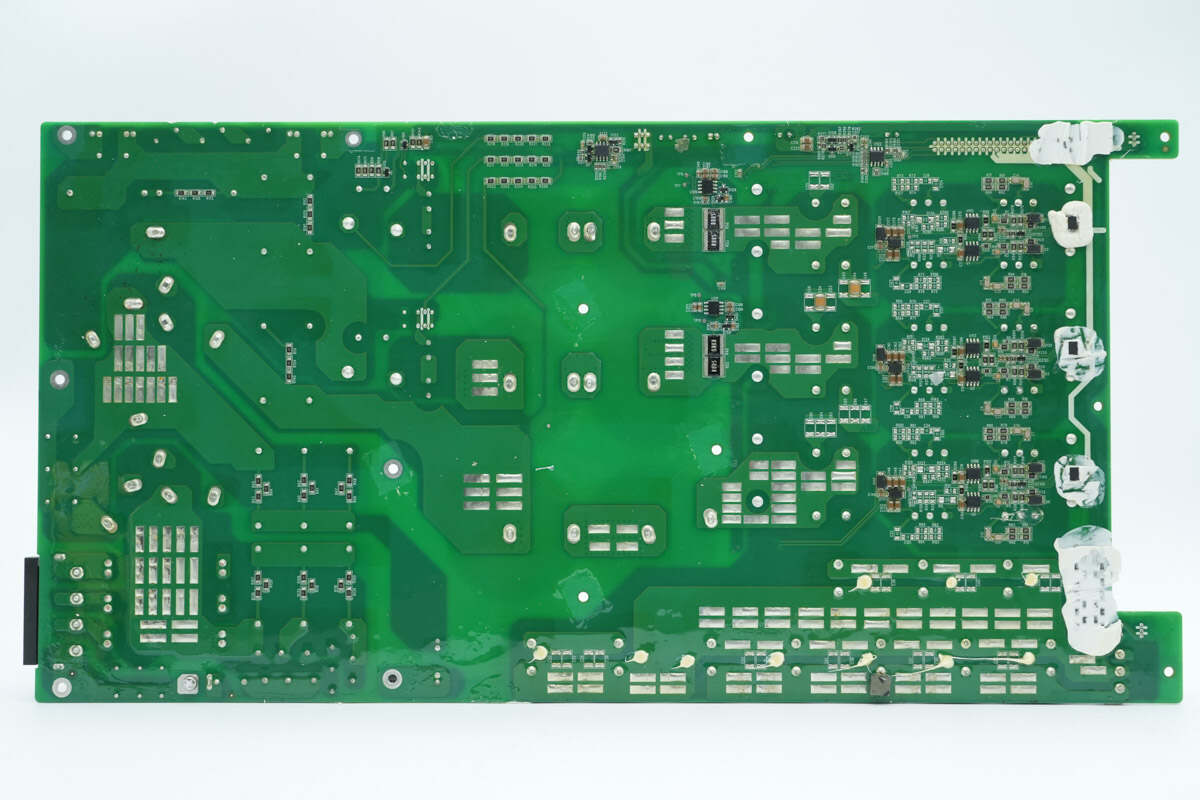
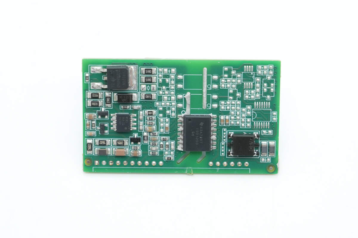
On the back side, there are the master control IC, current sense resistors, voltage regulators, an operational amplifier, gate drivers, and an optocoupler.
Remove the control PCB and one of the heatsinks.
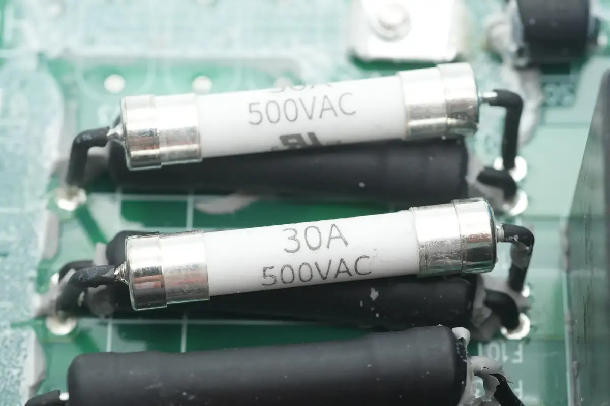
The input fuses are rated at 30A 500VAC, with two fuses connected in parallel for each phase. They are insulated with heat-shrink tubing.
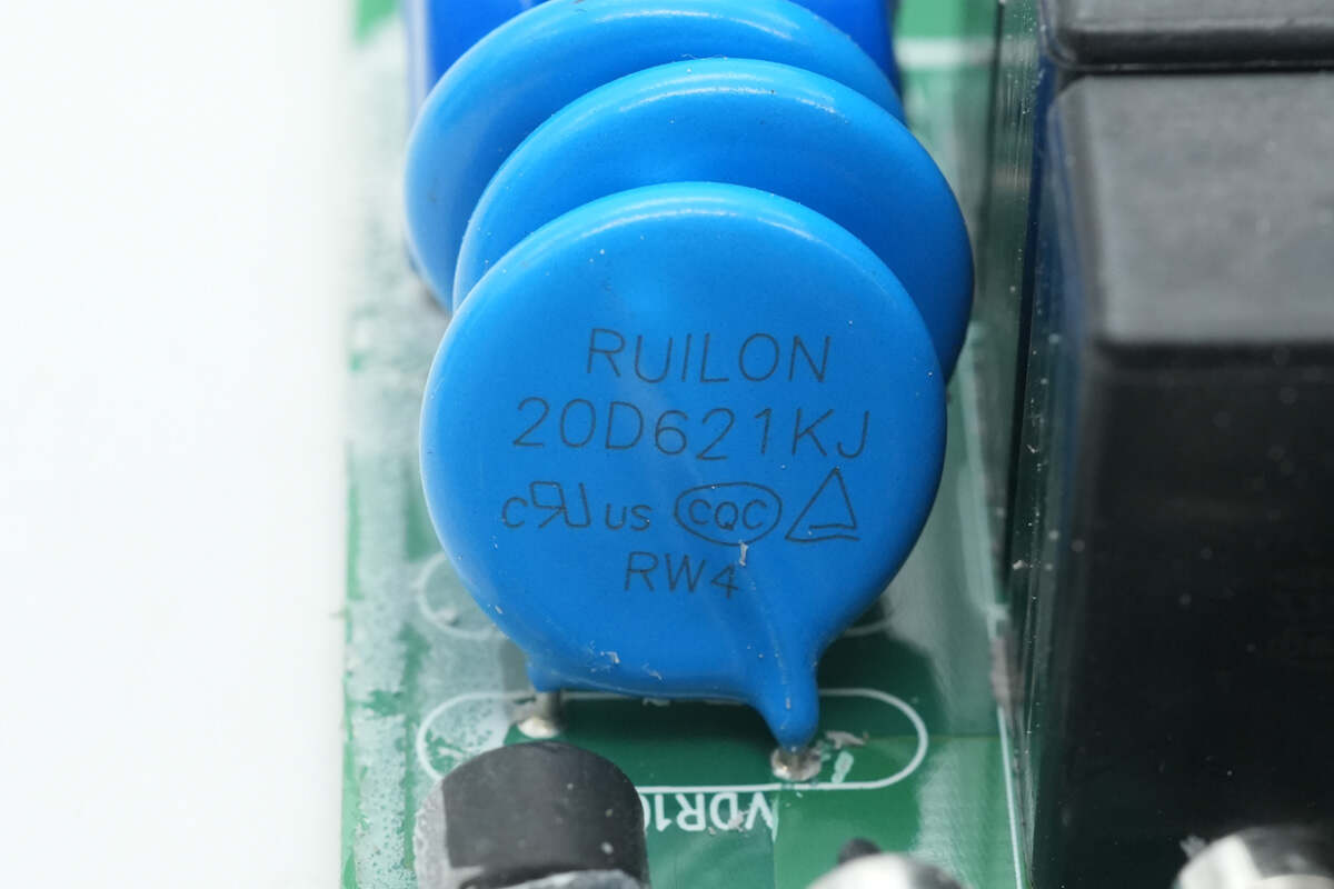
Three varistors from RUILON, model 20D621KJ, are used to absorb overvoltage surges.
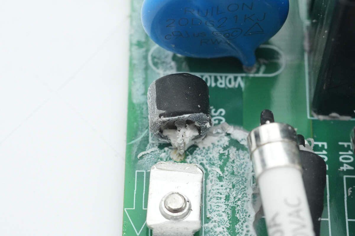
The gas discharge tube is insulated with heat-shrink tubing.
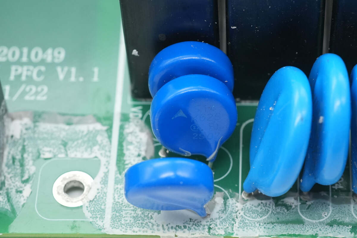
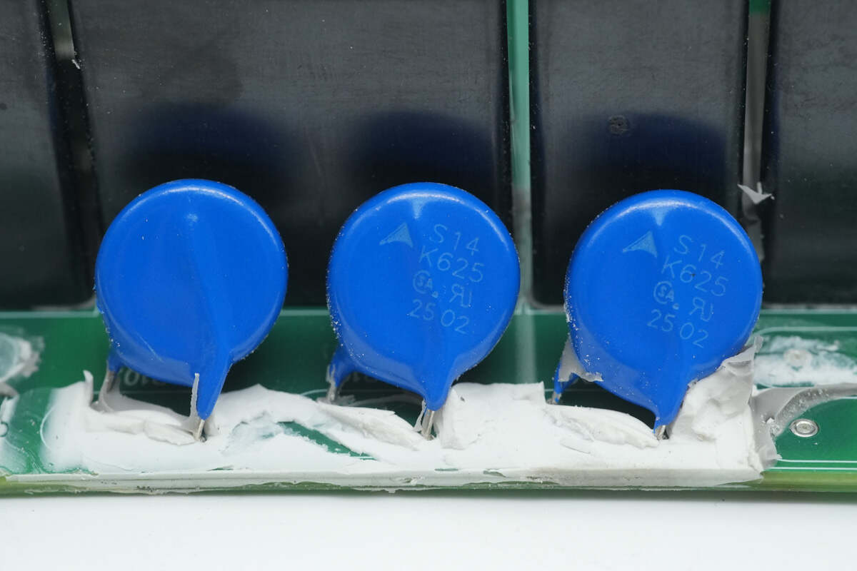
Three varistors from TDK, marked with silk screen S14K625, are used to absorb overvoltage surges.
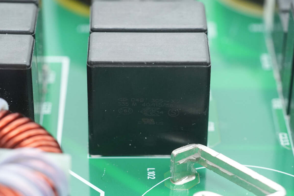
The safety X2 capacitors come from Faratronic, with a specification of 3.3μF, totaling 12 units.
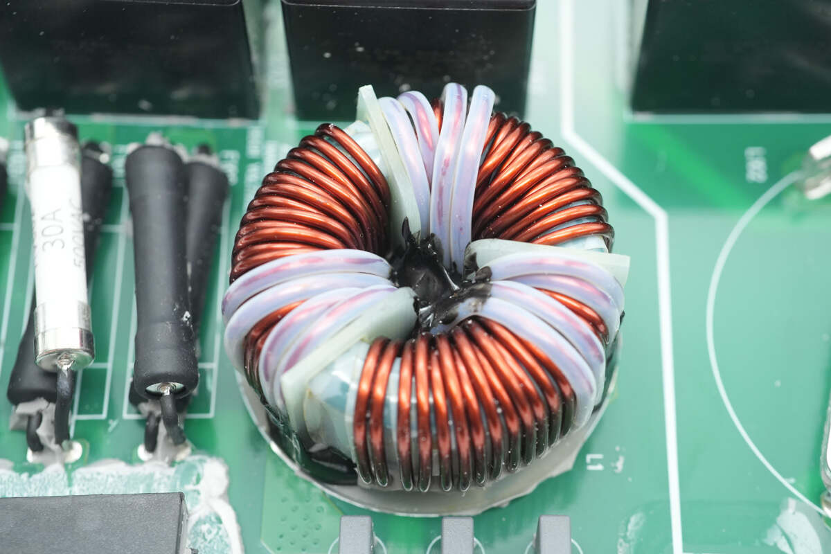
The common mode choke is wound with enamel-coated wire.

Close-up of the three film Y capacitors.
The output side is equipped with three varistors to absorb overvoltage surges.
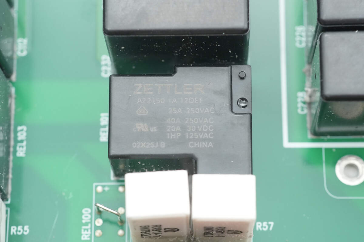
The soft-start relay is from ZETTLER, model AZ2150 1A-12DEF. It features a single normally open contact with a contact rating of 40A and a coil voltage of 12V, and it has Class F insulation.
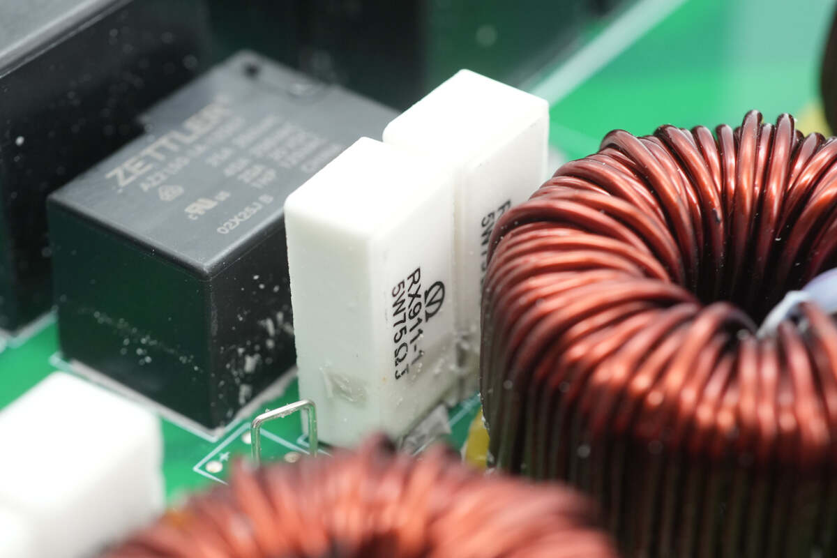
The soft-start resistors are wirewound RX911 type from Yongxing, rated at 5W 75Ω each, connected in series.
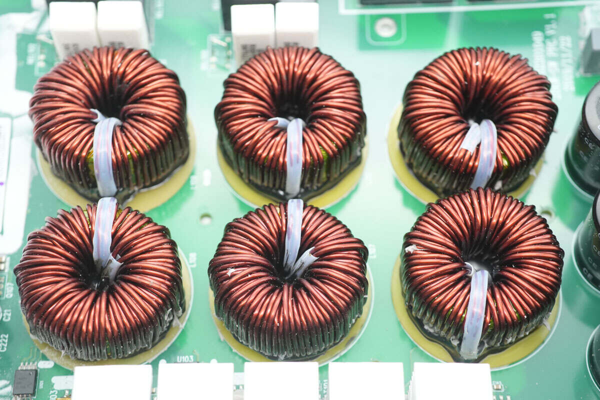
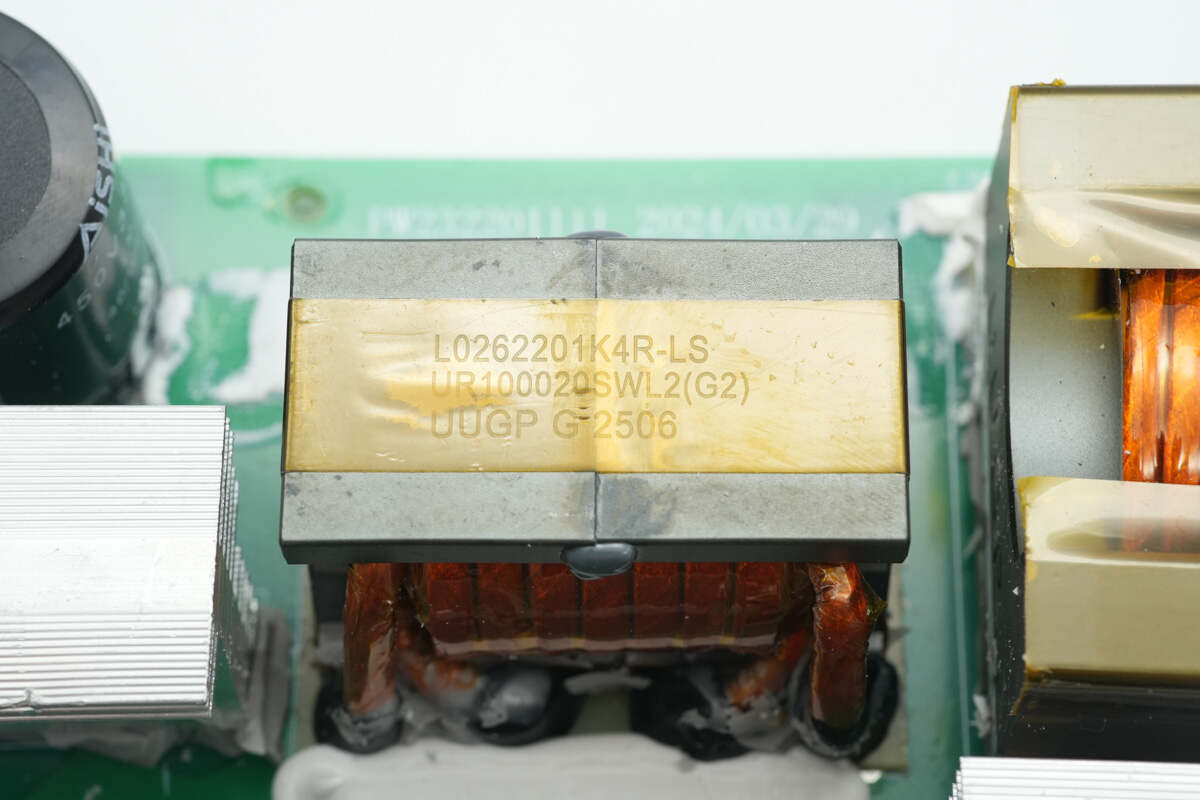
The PFC inductors use ferrite core winding, with a bakelite insulating board at the base.
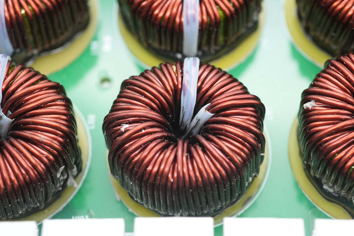
The PFC inductors are wound using bifilar (dual-wire) winding.
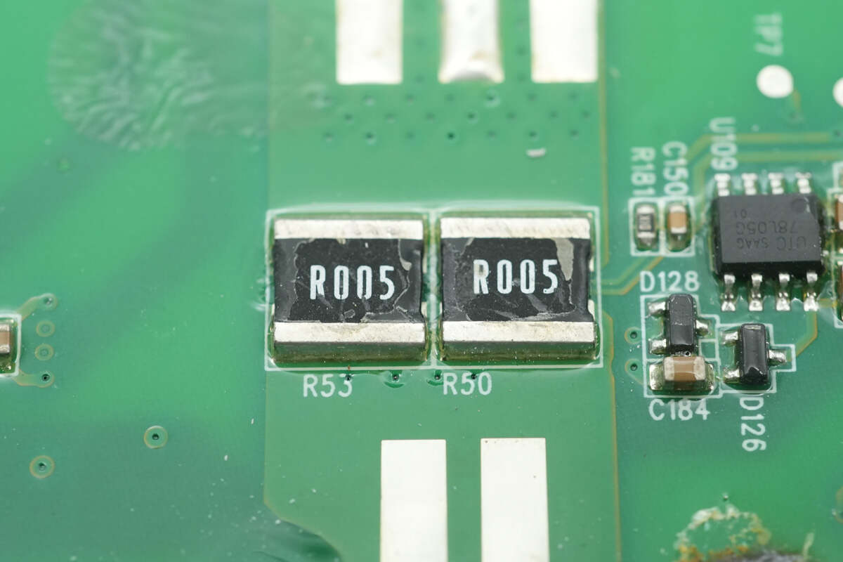
Two 5mΩ sense resistors are connected in parallel to measure the input current.
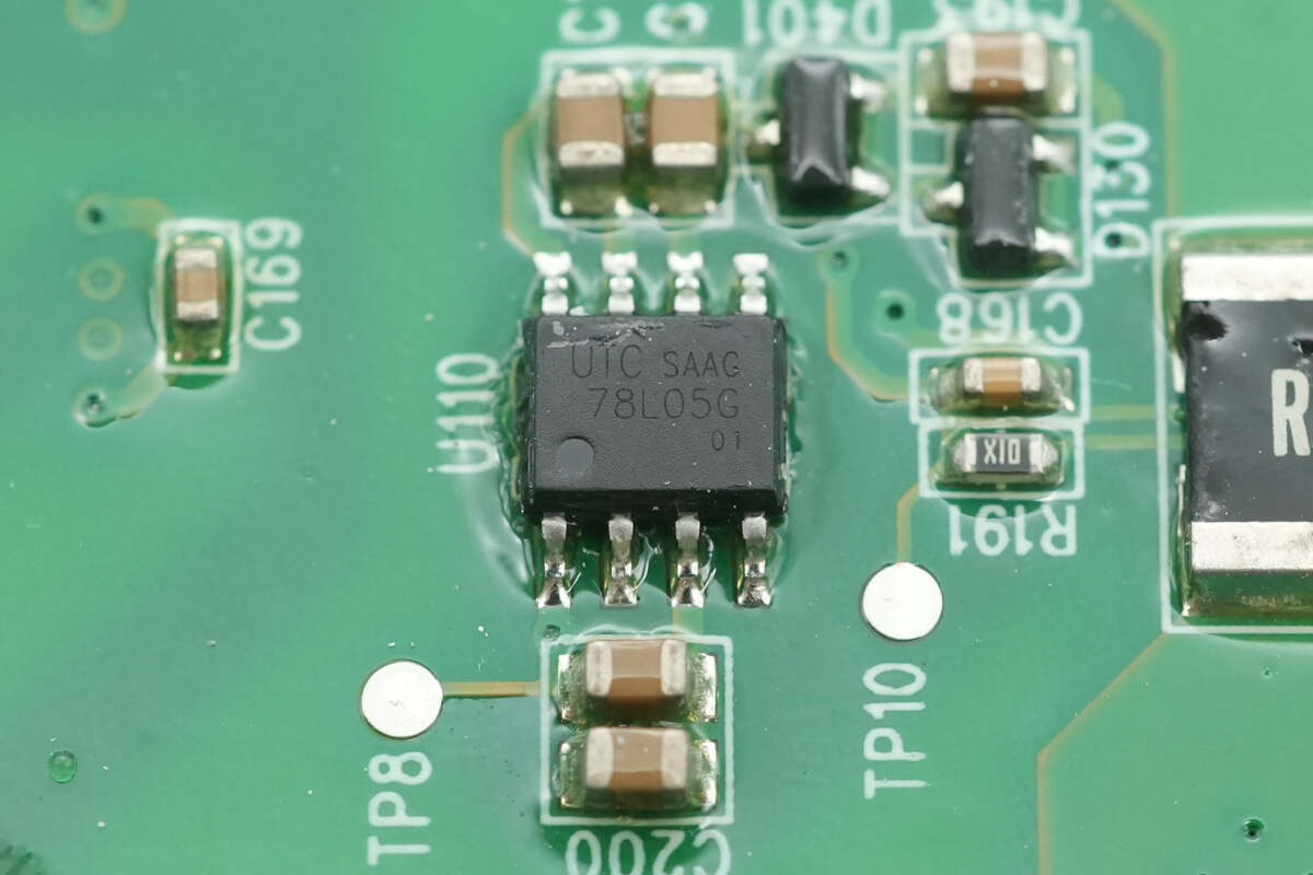
The voltage regulator chip is from Unisonic, model UTC78L05G. It supports an input voltage of up to 30V, outputs 5V at 100mA, and comes in an SOP-8 package.
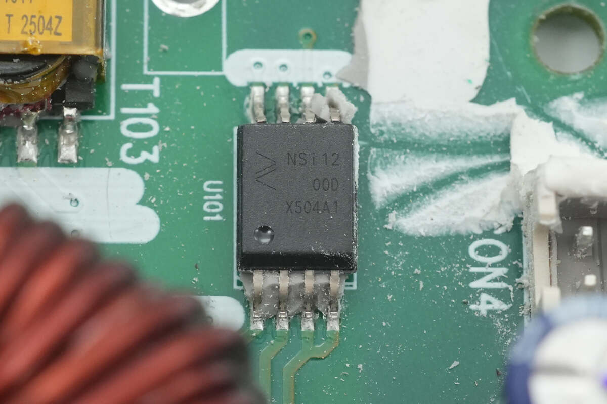
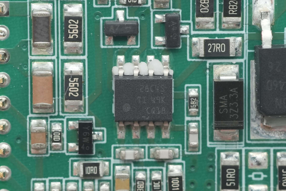
The isolation amplifier is from NOVOSENSE, model NSi1200. It is an isolated current-sensing operational amplifier supporting 5000Vrms insulation voltage and comes in an SOW8 package.
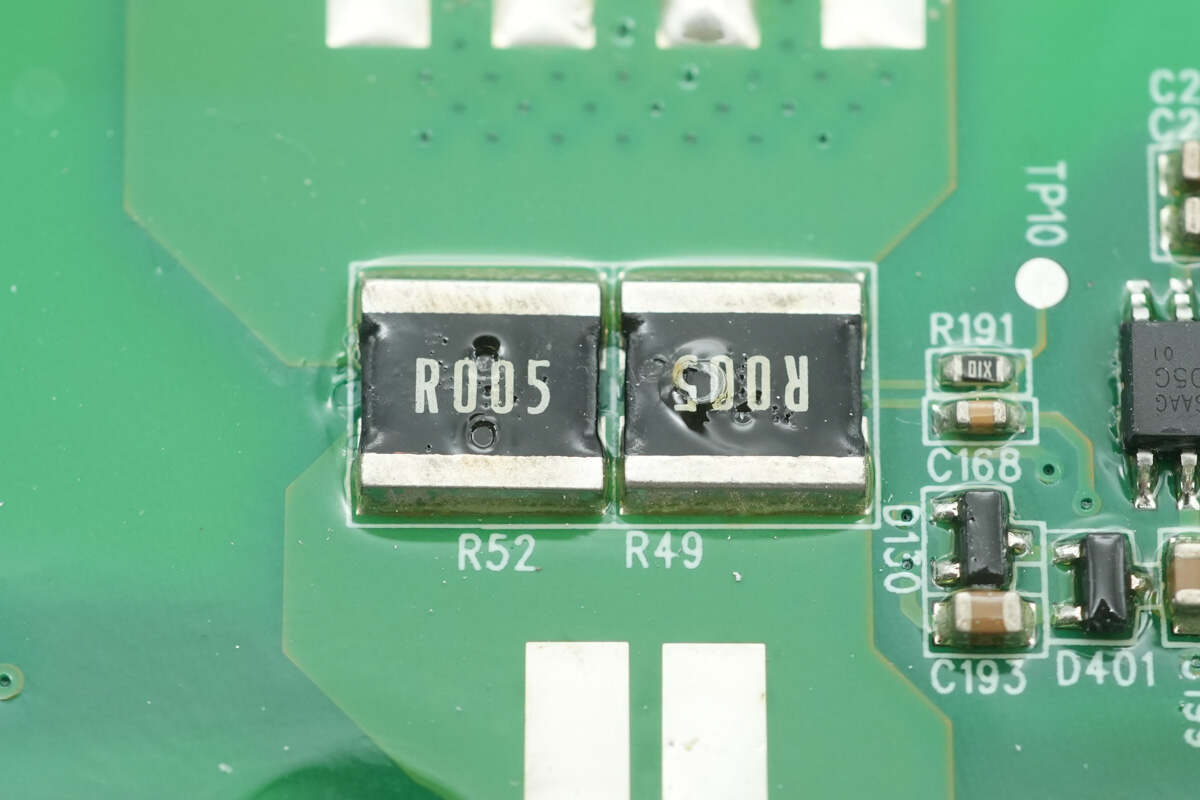
The other set of current sense resistors has the same specifications.
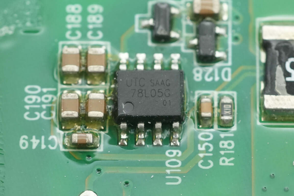
The voltage regulator chip used is the Unisonic UTC78L05G.
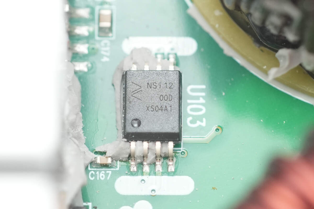
The isolation amplifier used is the NOVOSENSE NSi1200.
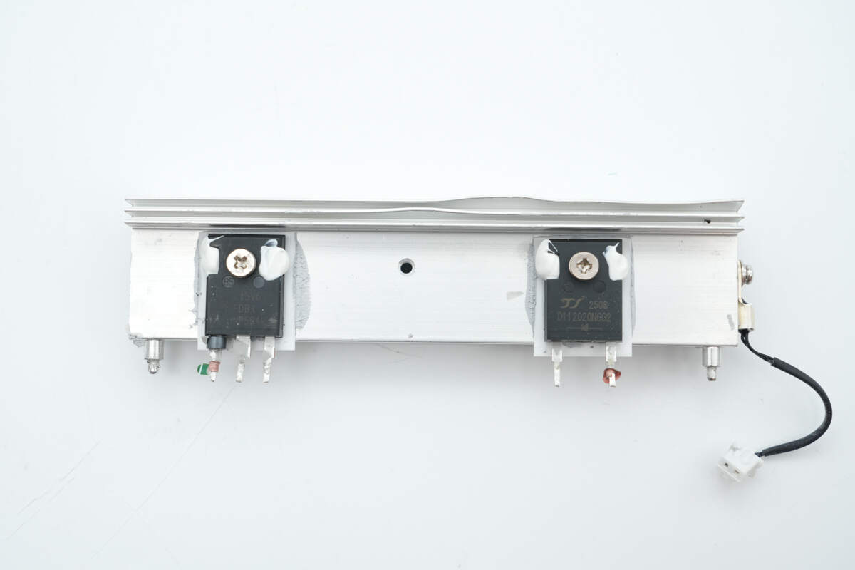
The heatsink secures a PFC MOSFET and a rectifier.
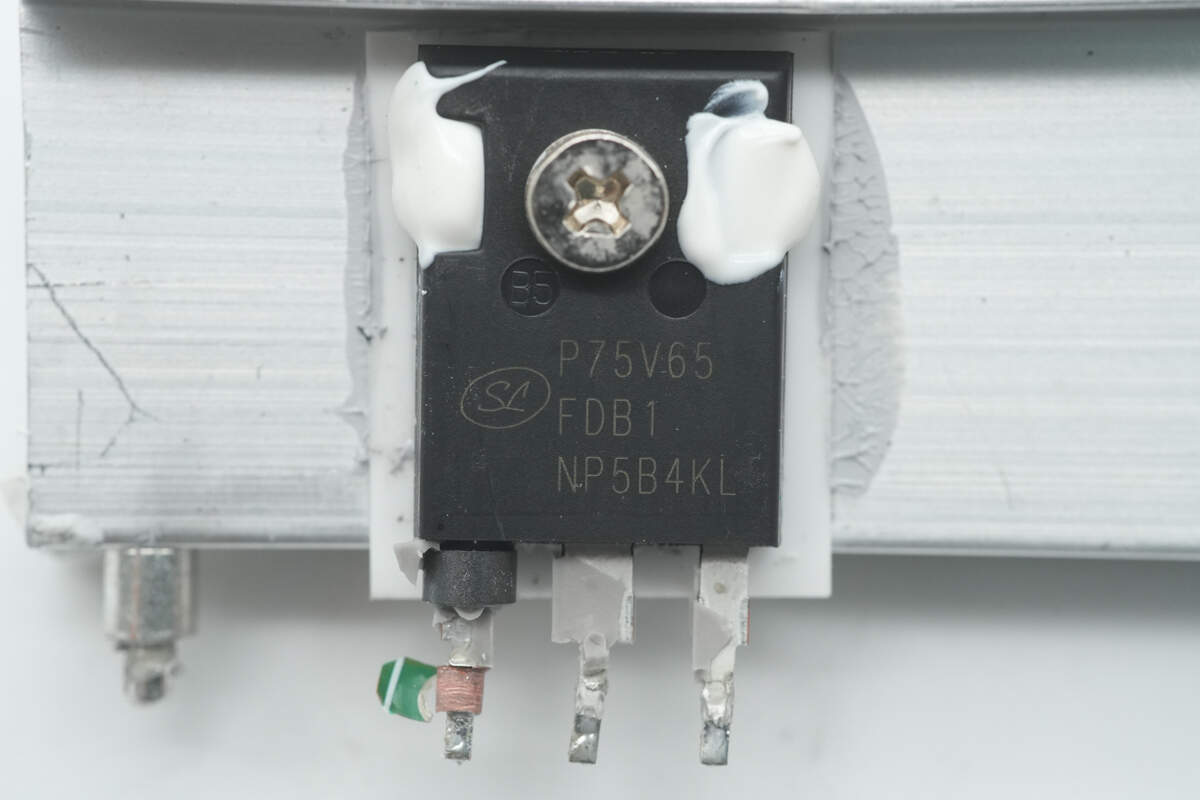
The PFC MOSFETs are from Silan, model SGTP75V65FDB1P7. They are high-speed IGBTs rated at 650V and 75A, packaged in TO-247-3L.

The PFC rectifiers are from YJ, model YJD112020NGG2. They are SiC diodes rated for 1200V and 33A, packaged in TO-247AC.
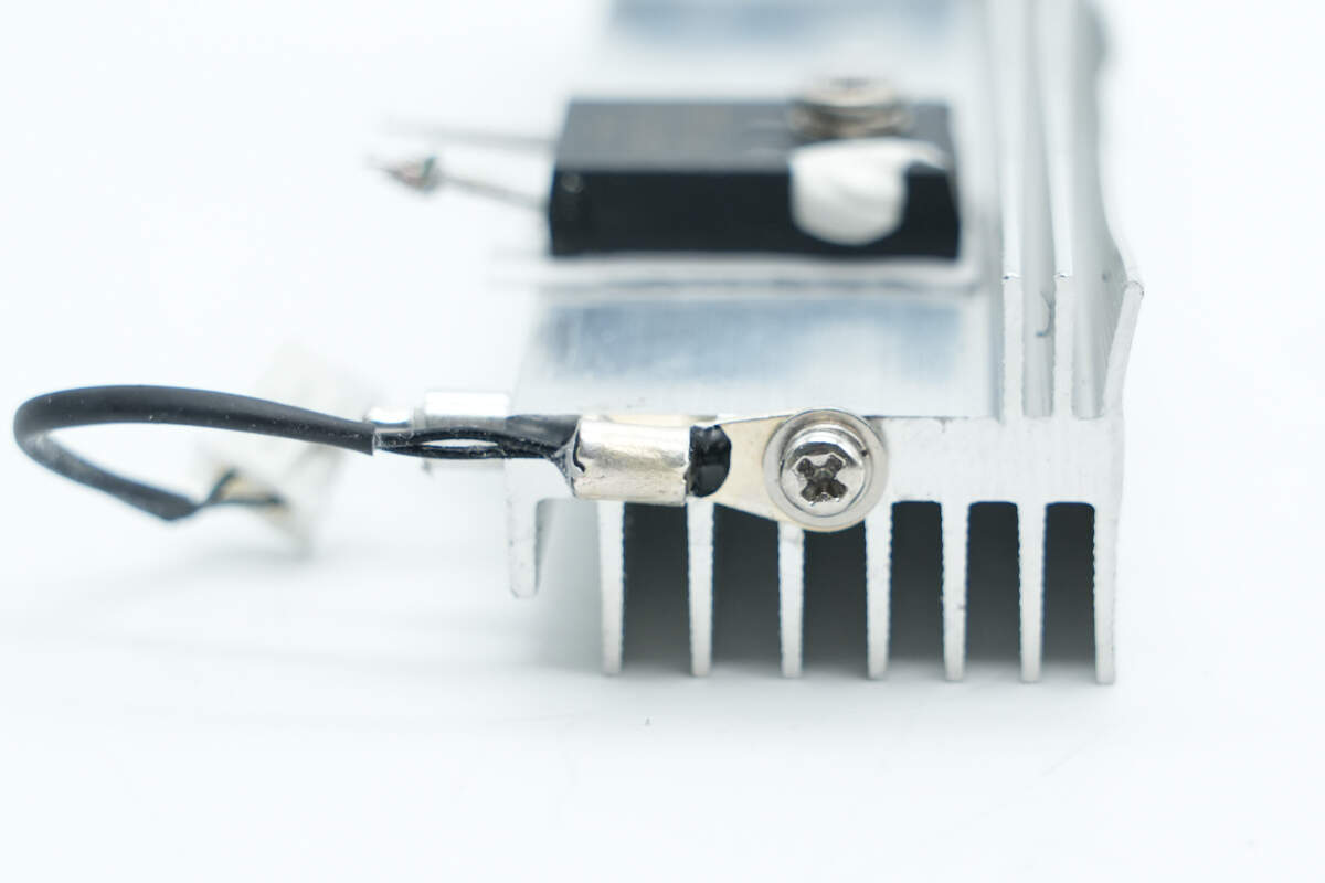
A thermistor is installed on the side of the heatsink to monitor temperature rise.
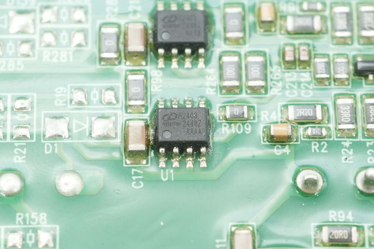
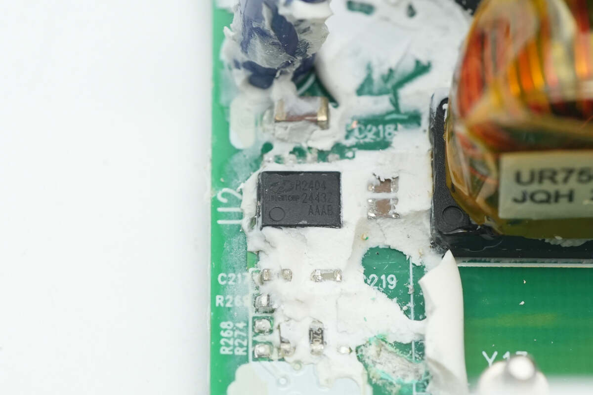
The driver for the PFC MOSFETs is from IVCT, model IVCR2403. It is a dual-channel low-side high-speed gate driver supporting both MOSFET and IGBT applications, with a wide 24V power supply range and an operating temperature range of -40 to 125°C. It comes in an SOIC-8 package.
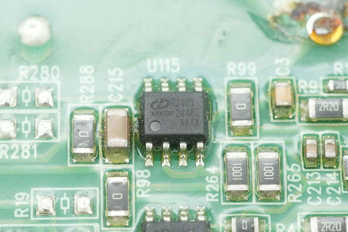
There is another driver of the same model, making a total of six drivers corresponding to six PFC MOSFETs.
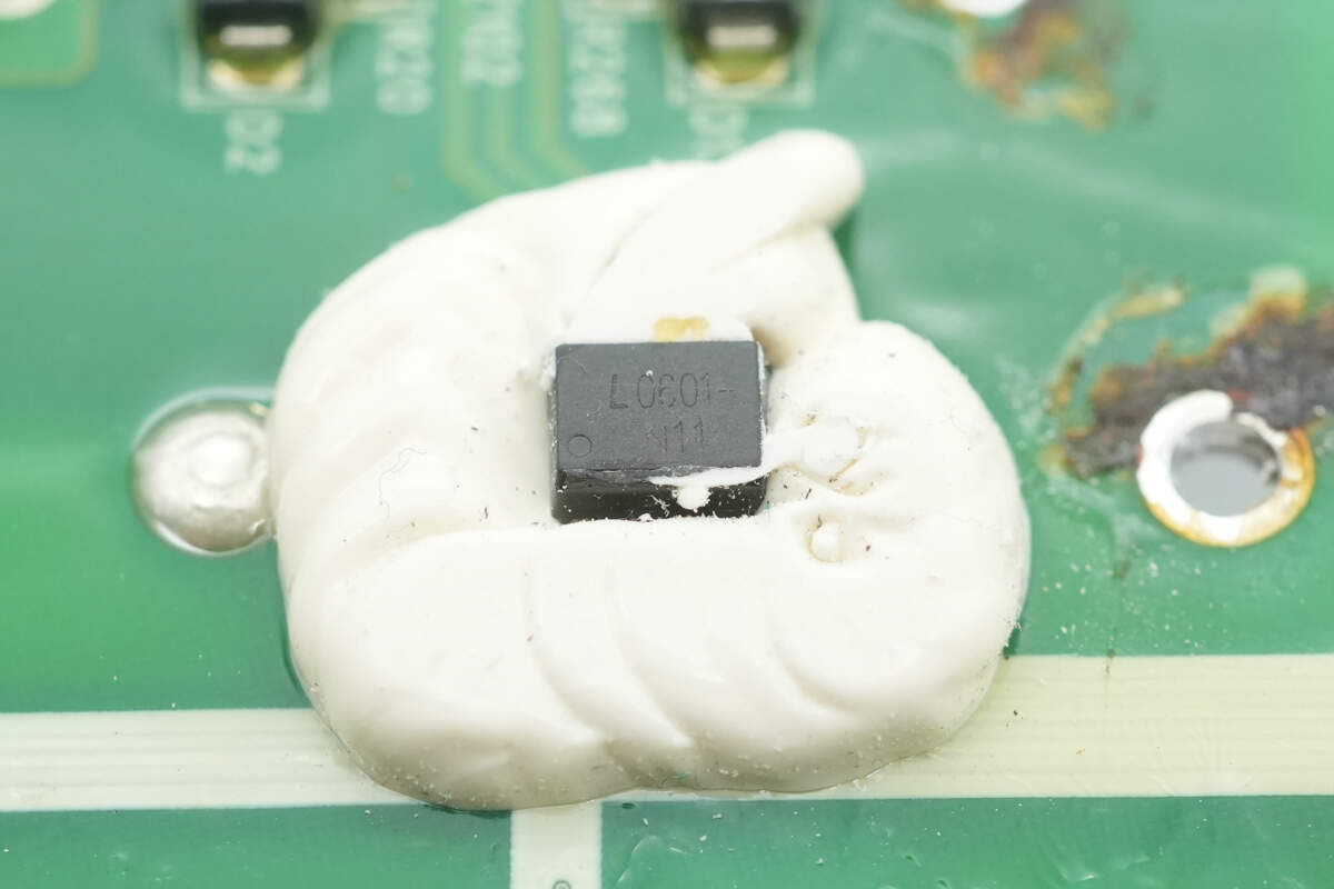
The control signals are isolated via optocouplers from LITEON, model LTV-0601. These are single-channel isolation optocouplers supporting 3.3V/5V operating voltages and come in an SOP-8 package.
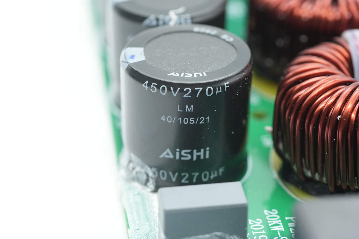
The high-voltage filter capacitors are from AiSHi, part of the LM series of compact, long-life electrolytic capacitors, rated at 450V 270μF.
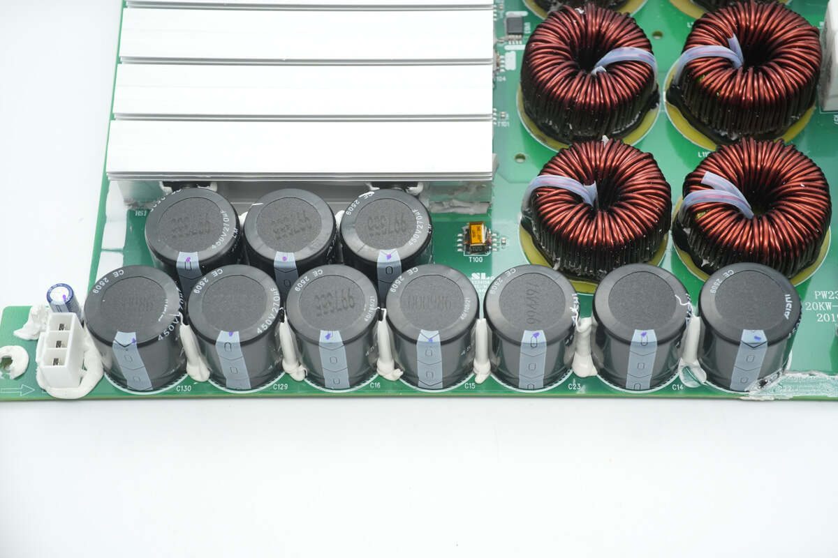
There are a total of 10 capacitors connected as 5 in parallel and 2 in series, resulting in an equivalent rating of 900V and 675μF.
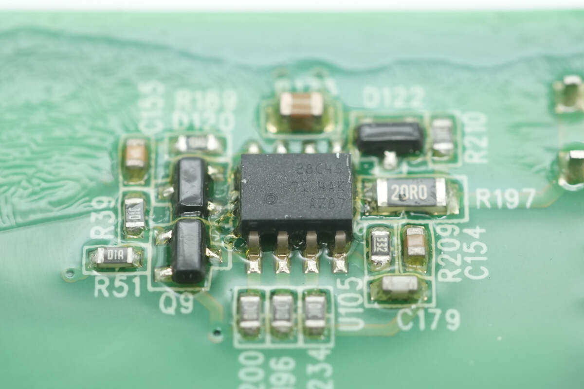
The master power control chip is from Texas Instruments, model UCC28C45. It is a low-power current-mode controller supporting a switching frequency of 1MHz and comes in an SOIC-8 package.
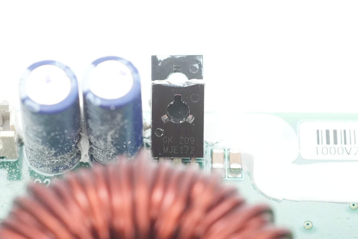
Two transistors from GK. One of the two has the model of MJE172, which is a PNP-type transistor rated for 80V and 3A collector current, packaged in TO-126.
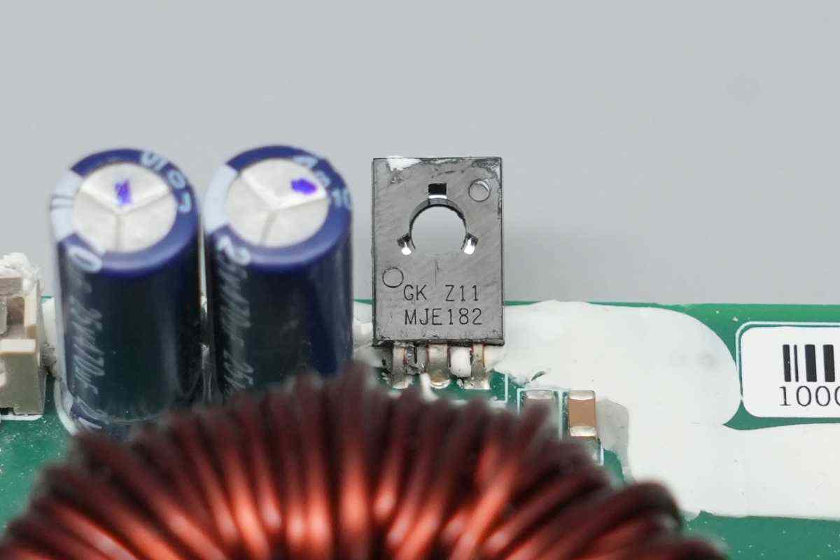
The other transistor, model MJE182, is an NPN transistor rated for 80V and 3A collector current, packaged in TO-126.
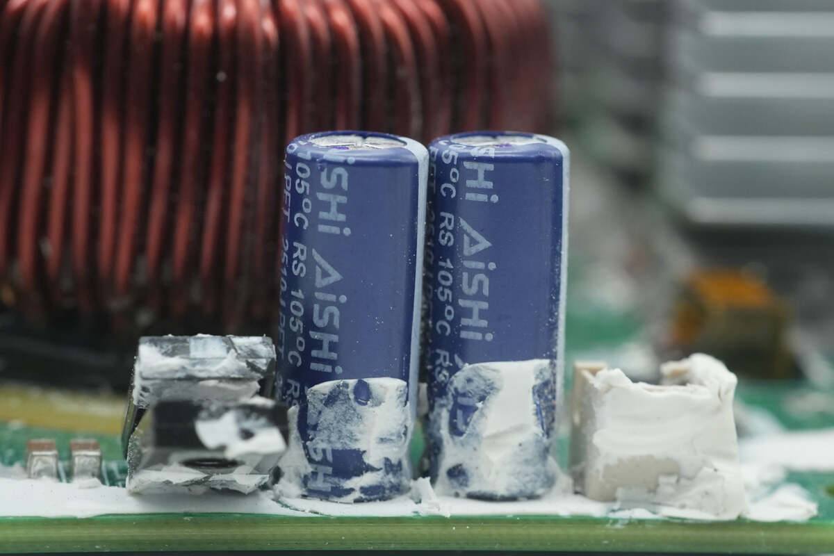
The two filter capacitors are from AiSHi.
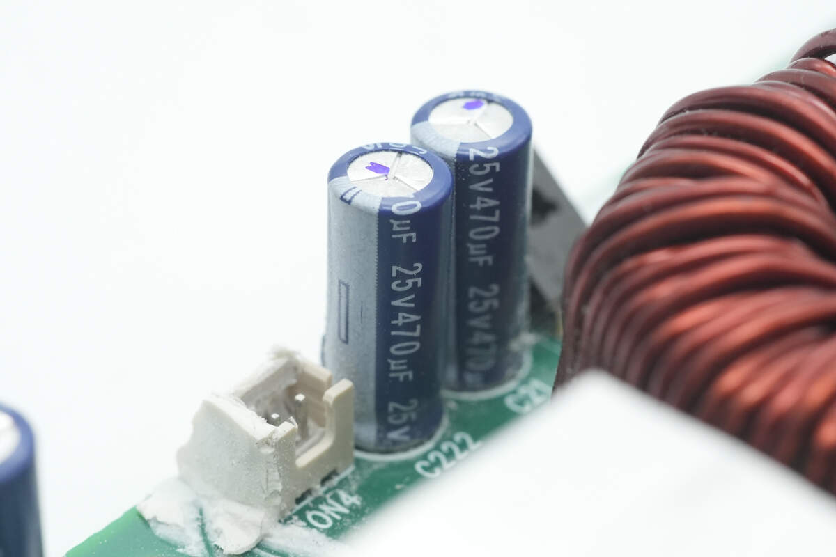
Both are rated at 25V and 470μF.
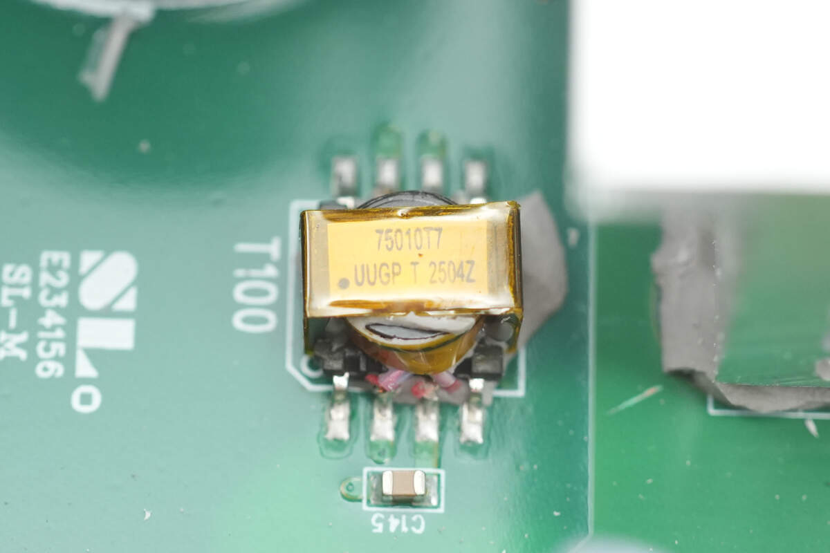
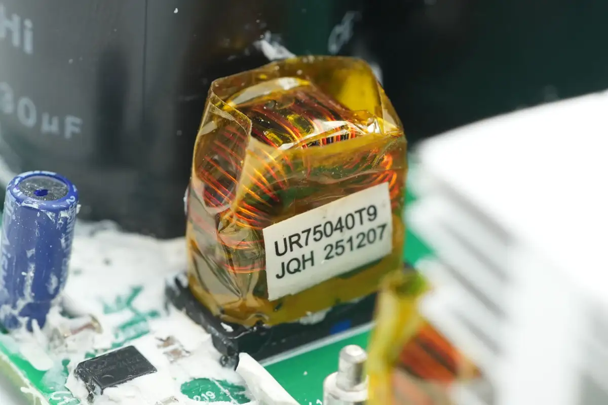
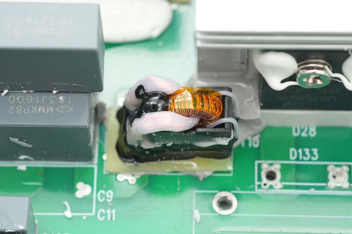
Close-up of the isolation transformer that powers the drivers.
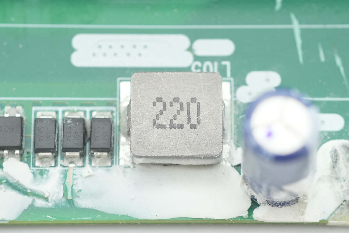
Close-up of the 22μH alloy inductor.
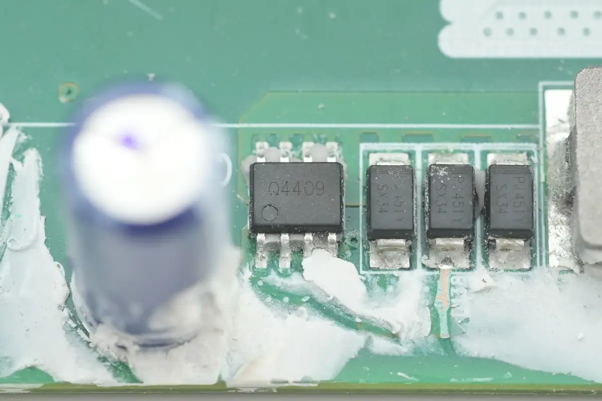
The MOSFET is marked with Q4409.
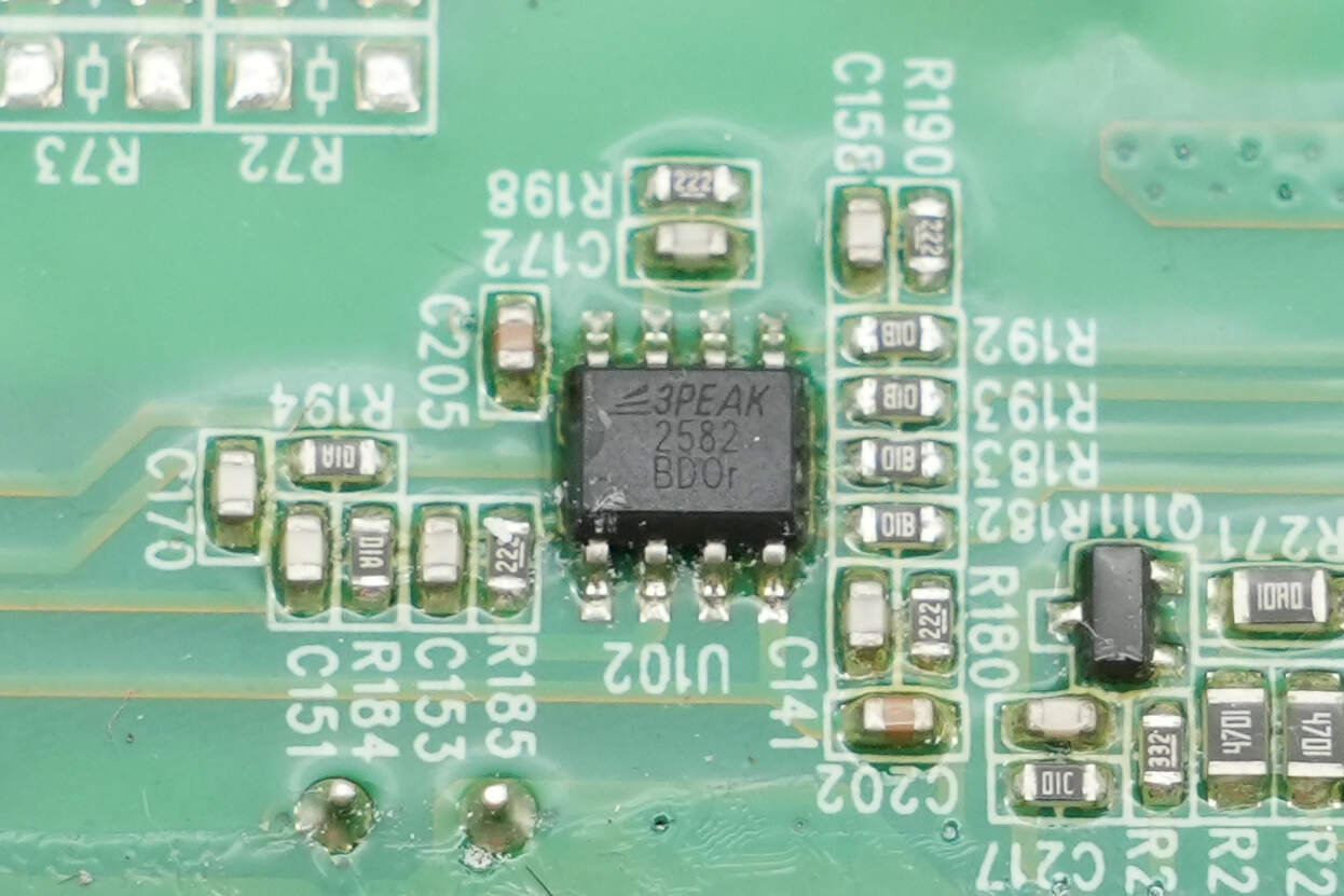
The operational amplifier is from 3PEAK, model TP2582. It features low offset voltage, low power consumption, and stable high-frequency response, and comes in an SOP-8 package.
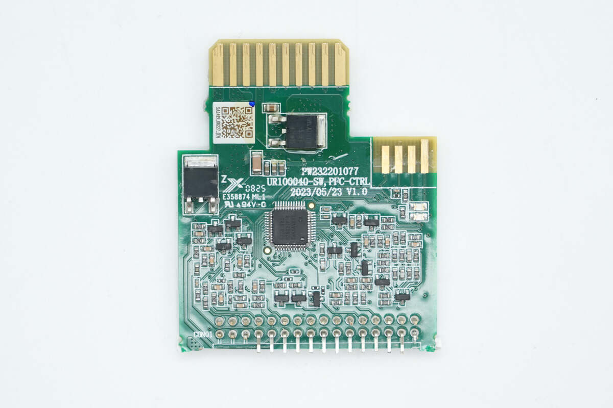
The front side of the PFC control PCB features the PFC controller and two voltage regulator chips.
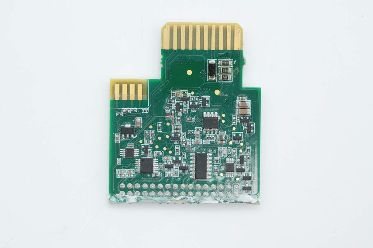
The back side is equipped with a voltage regulator chip, voltage comparators, an operational amplifier, and an AND gate IC.
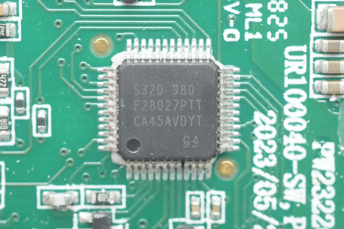
The PFC controller is from Texas Instruments, model TMS320F28027PT. It features a high-performance 32-bit CPU running at 60MHz, with 64KB FLASH and 12KB SRAM. It supports 8-channel PWM output and includes I2C, SPI, and UART communication interfaces. The package type is LQFP48.
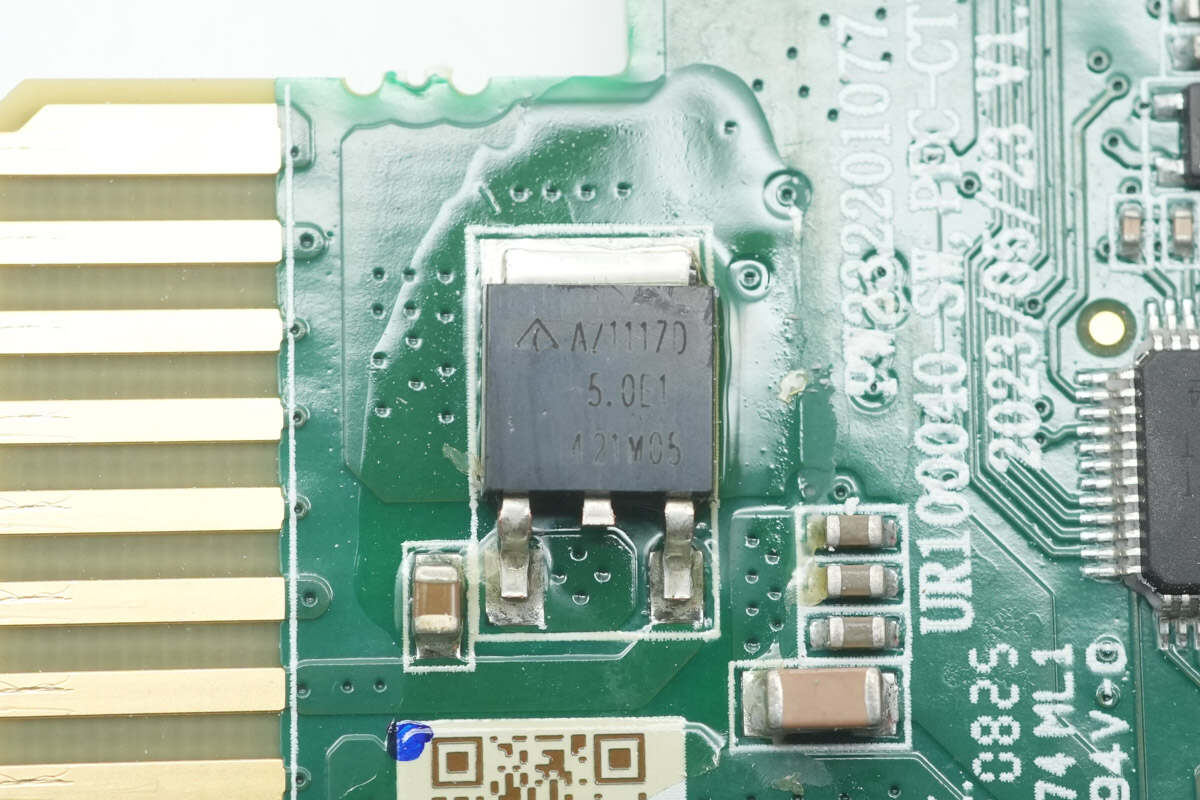
The voltage regulator chip is from DIODES, model AZ1117D-5.0TRE1. It supports a 20V input voltage, outputs 5V at 1A, and comes in a TO252-2 package.

The other voltage regulator chip is model AZ1117D-3.3TRE1, with an output voltage of 3.3V.
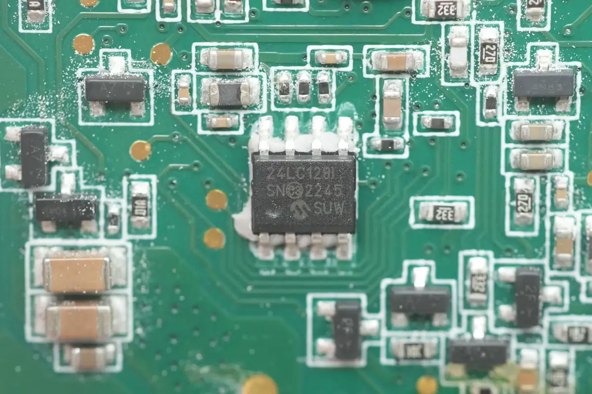
The memory chip is from Microchip, model 24LC128I, with a capacity of 16KB. It supports an operating voltage of 2.5–5.5V and comes in an SOIC-8 package.
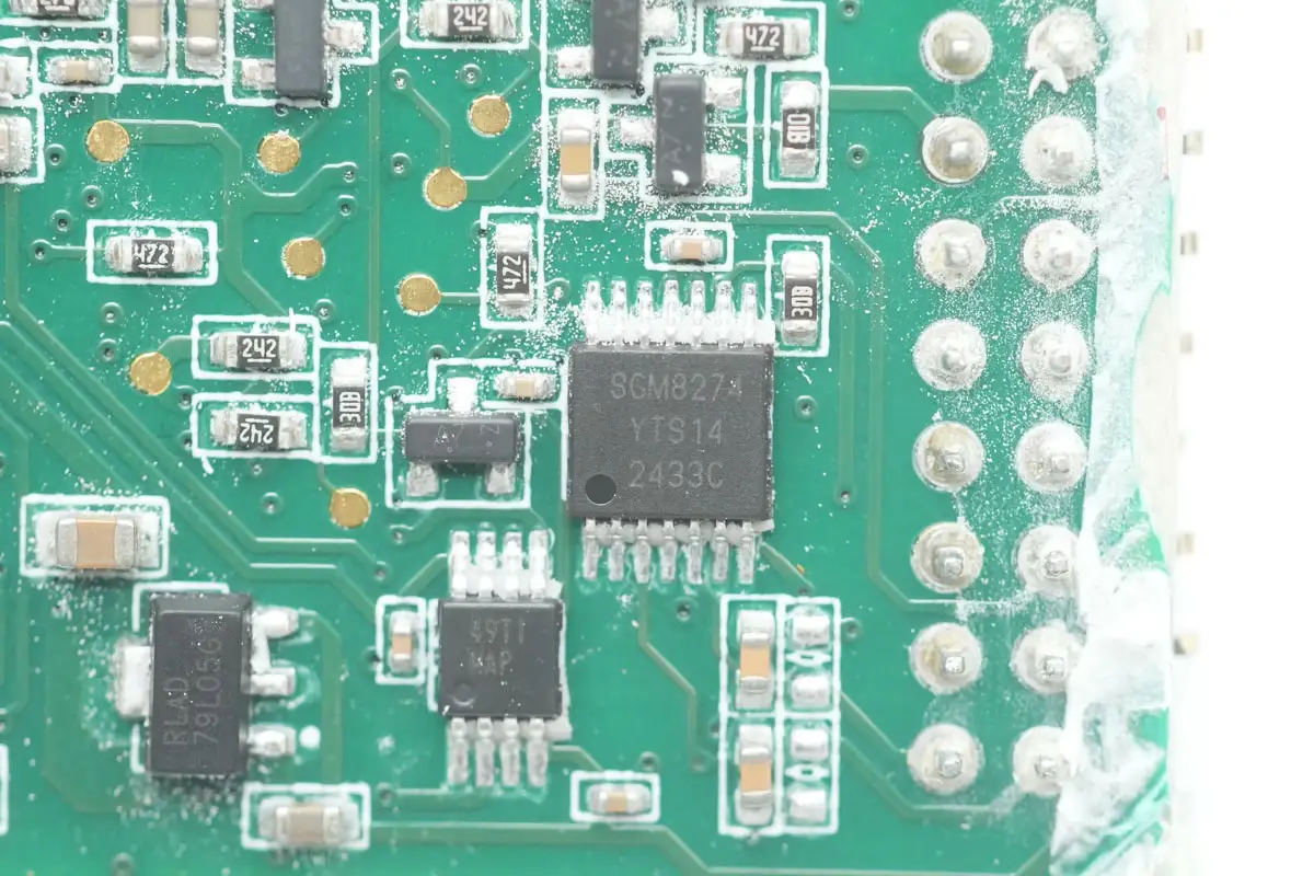
The operational amplifier is from SGMICRO, model SGM8274. It is a high-voltage, rail-to-rail output, four-channel op amp offering high slew rate, low offset voltage, low drift voltage, and low bias current. It comes in a TSSOP-14 package.
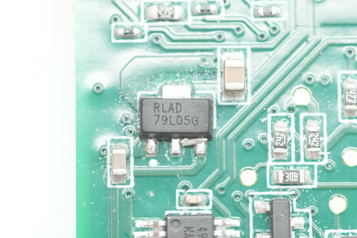
The voltage regulator chip marked with 79L05G comes in an SOT-89 package.
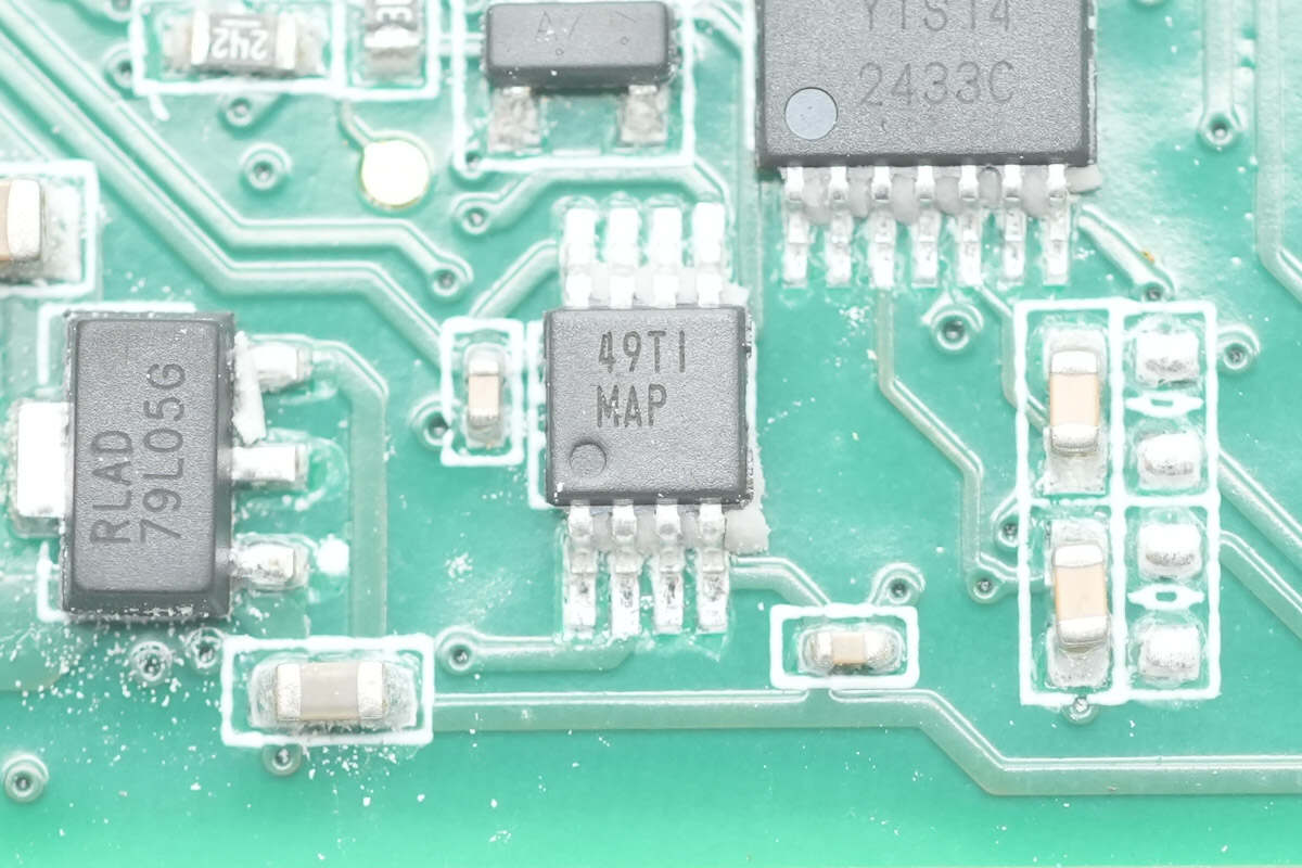
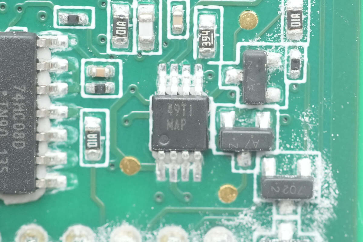
The voltage comparator is from Texas Instruments, marked with MAP, model LM2903. It is a general-purpose dual voltage comparator, packaged in VSSOP-8.
The other voltage comparator has the same model.

The AND gate chip is from Nexperia, model 74HC08D. It is a quad 2-input AND gate, packaged in SO14.
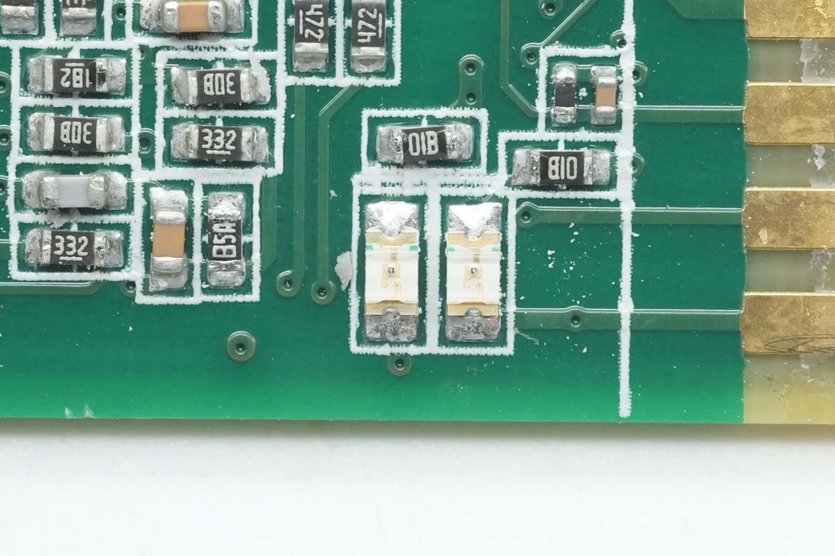
Close-up of two SMD LEDs.
The LLC module is secured inside the enclosure.
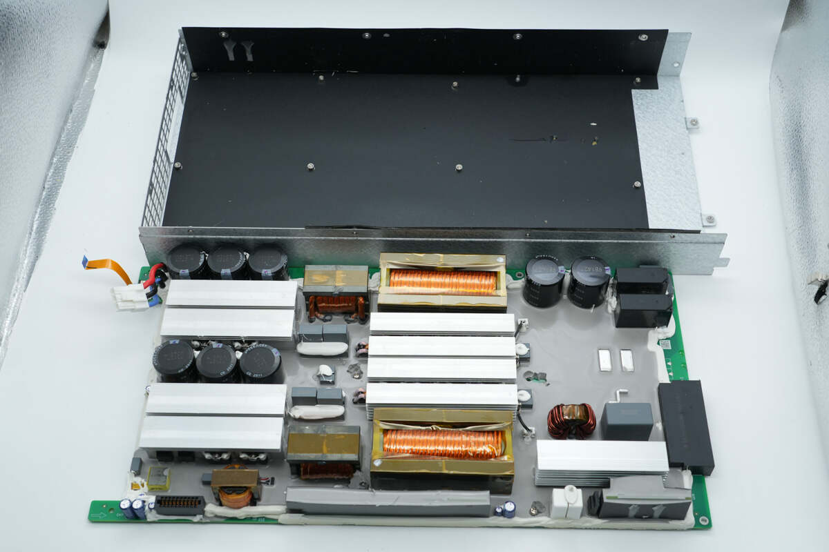
Remove the LLC module.
The PCBA module uses potting for sealing and moisture protection, enhancing reliability.
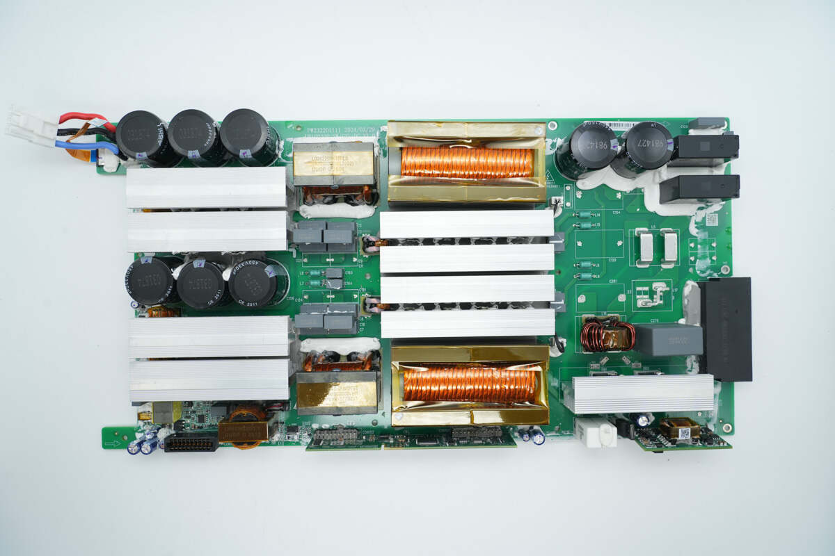
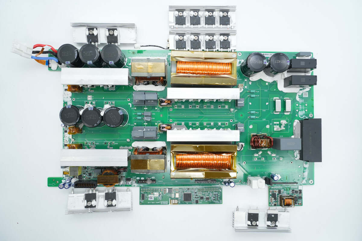
On the left side are high-voltage filter capacitors, MOSFETs, resonant capacitors, and a resonant inductor. The center area houses the LLC transformers, positioned both above and below. On the upper right are high-voltage filter capacitors and a relay, while below them are reverse-blocking diodes and the output connector. At the bottom are the control PCB and the auxiliary power PCB.
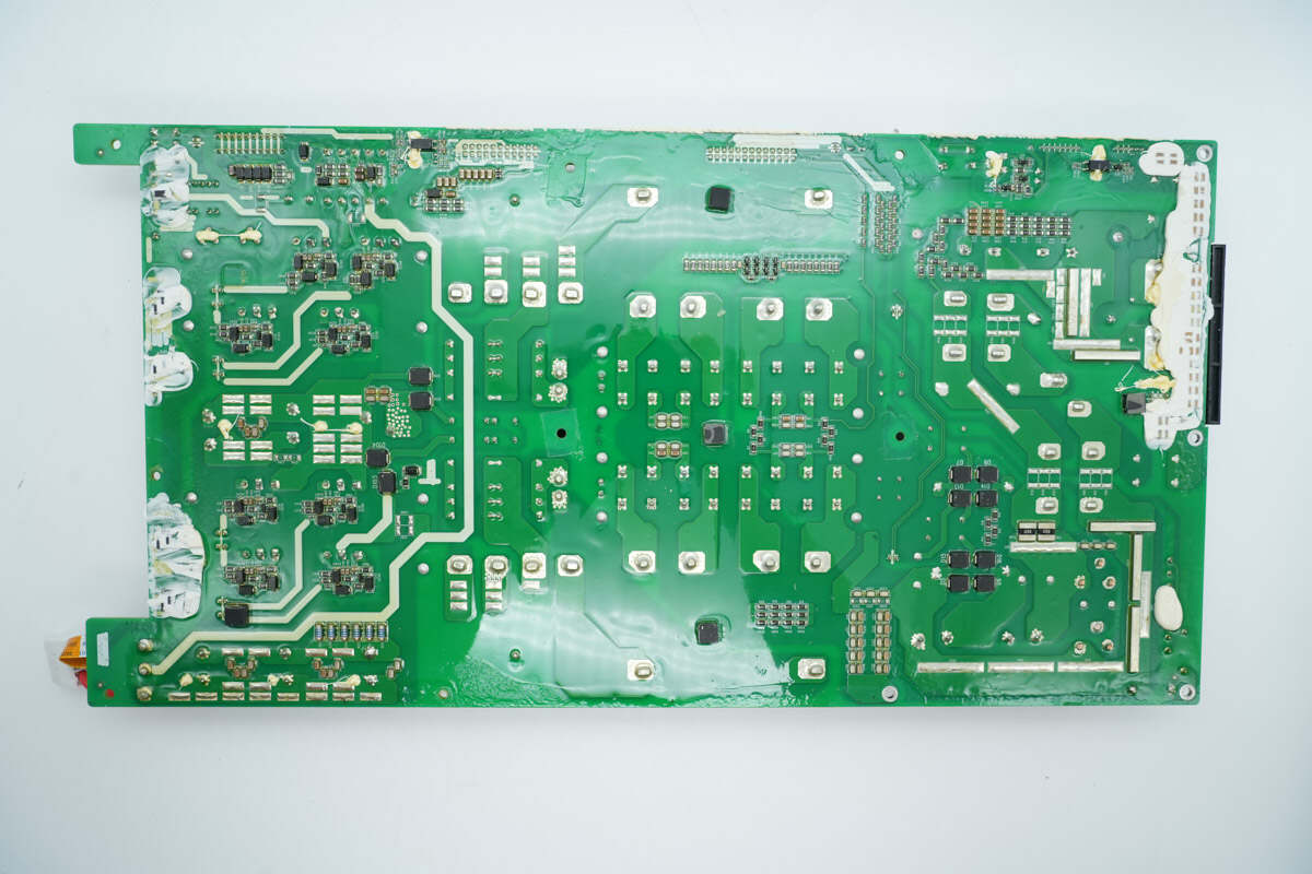
The back side contains resistor-capacitor components and diodes, along with sense resistors and optocouplers.
Remove the control PCB, auxiliary power PCB, LLC MOSFETs, rectifiers, and reverse-blocking diodes.
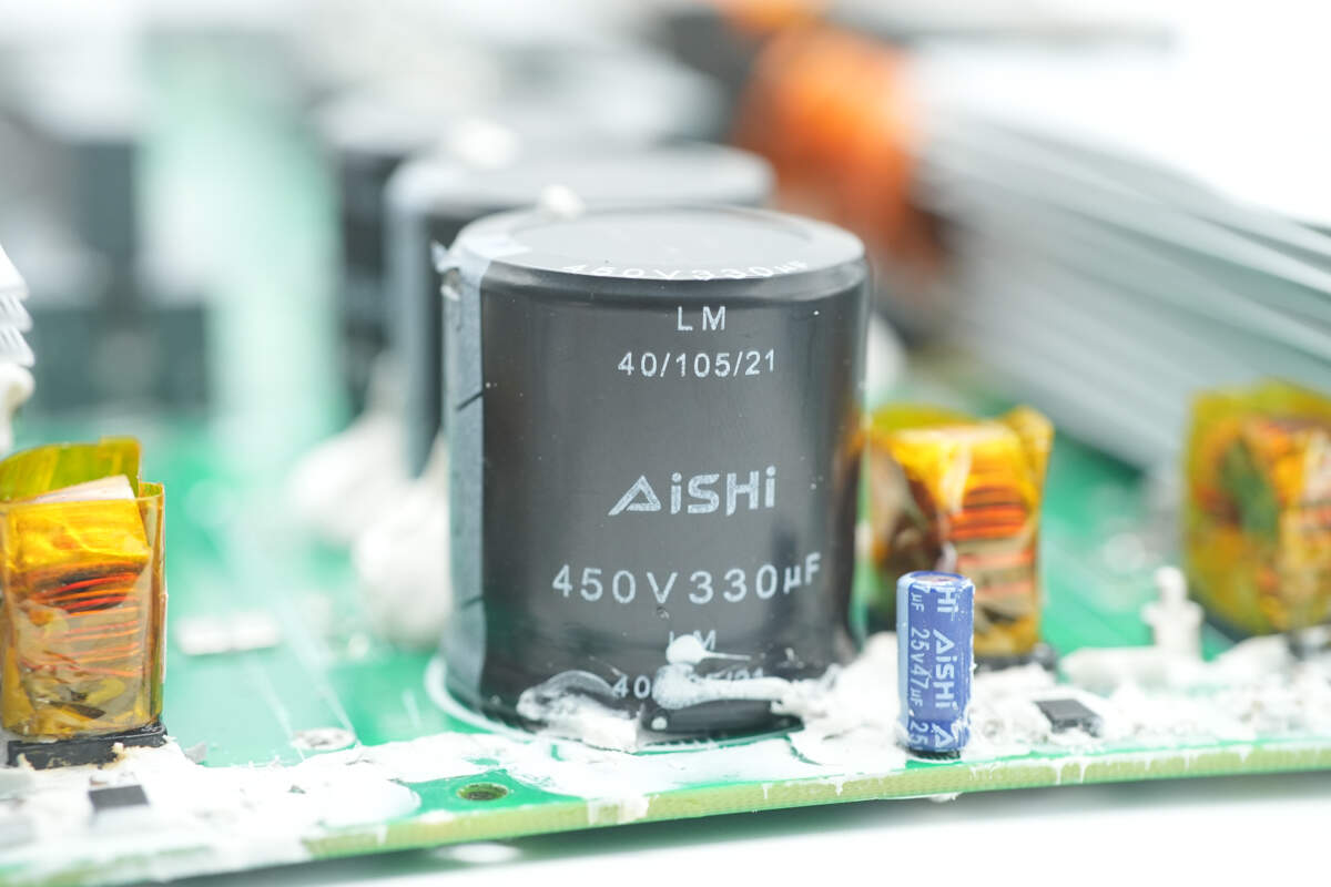
The high-voltage filter capacitors are from AiSHi, part of the LM series of compact, long-life electrolytic capacitors, rated at 450V 330μF.
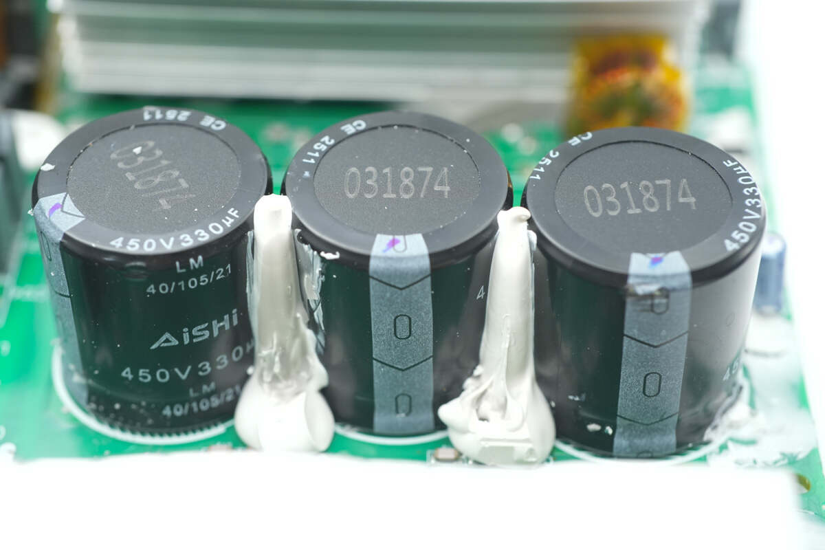
One group consists of three capacitors connected in parallel.
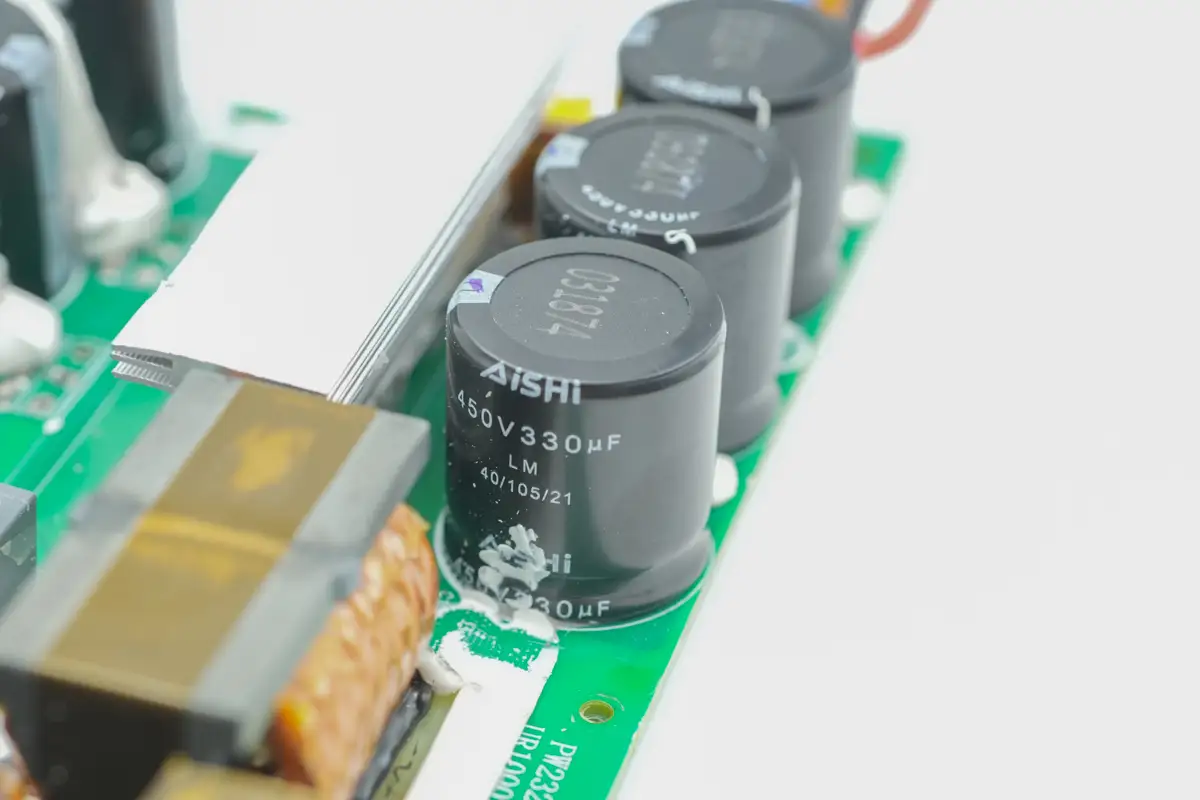
The other group of capacitors has the same specifications.
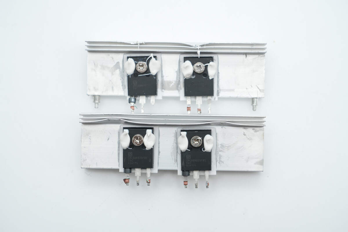
The full-bridge LLC MOSFETs are mounted on the heatsink.
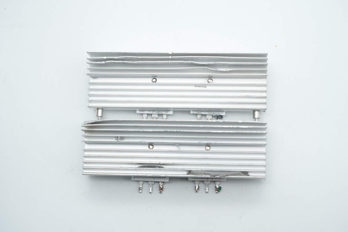
The back of the heatsink features fins to increase the cooling surface area.
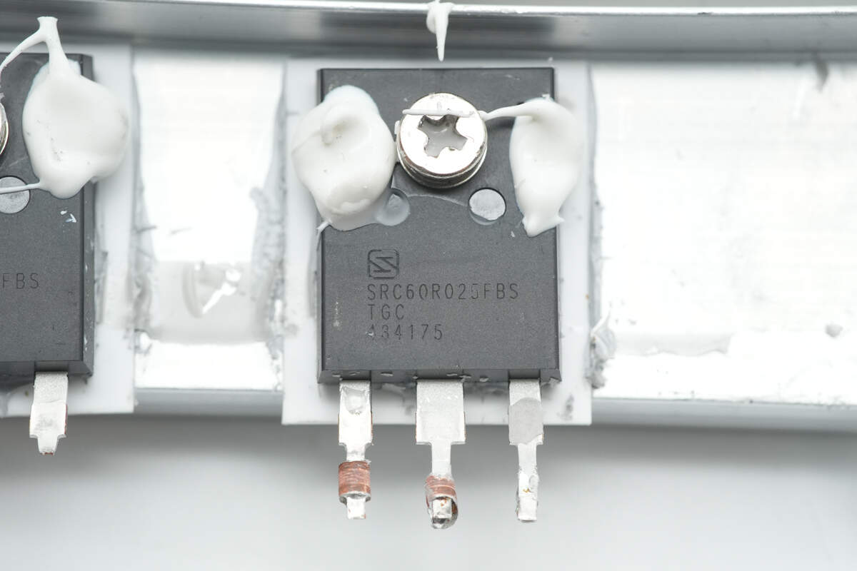
The LLC MOSFETs are from Sanrise, model SRC60R025FBS. They are NMOS devices rated at 600V and come in a TO-247 package.
The isolation transformers driving the MOSFETs are wrapped with high-temperature tape for insulation and mounted on plastic bases. There are four transformers in total, corresponding to eight MOSFETs.
The drivers are from IVCT, model IVCR2404. They are dual-channel low-side high-speed gate drivers, with four units corresponding to the four isolation transformers.
The resonant inductor is wound with Litz wire.
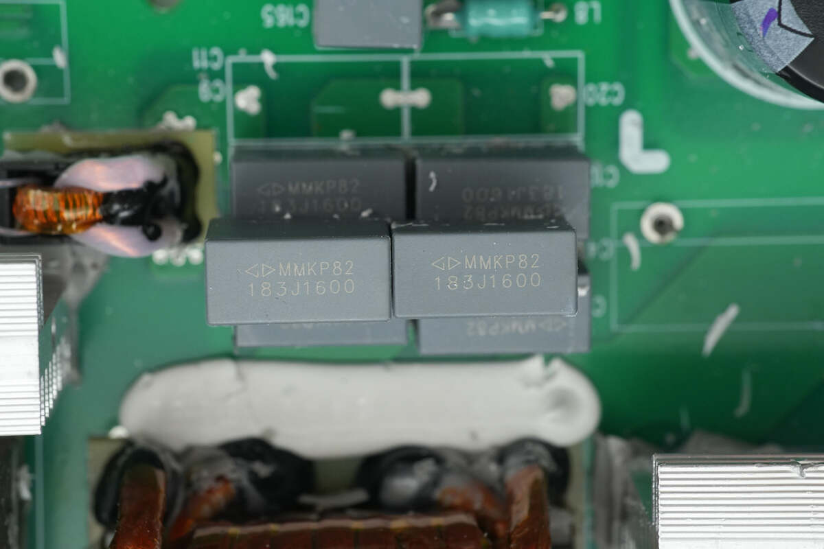
The resonant capacitors are from Faratronic, rated at 0.018μF 1600V, with a total of 12 capacitors arranged in two groups.
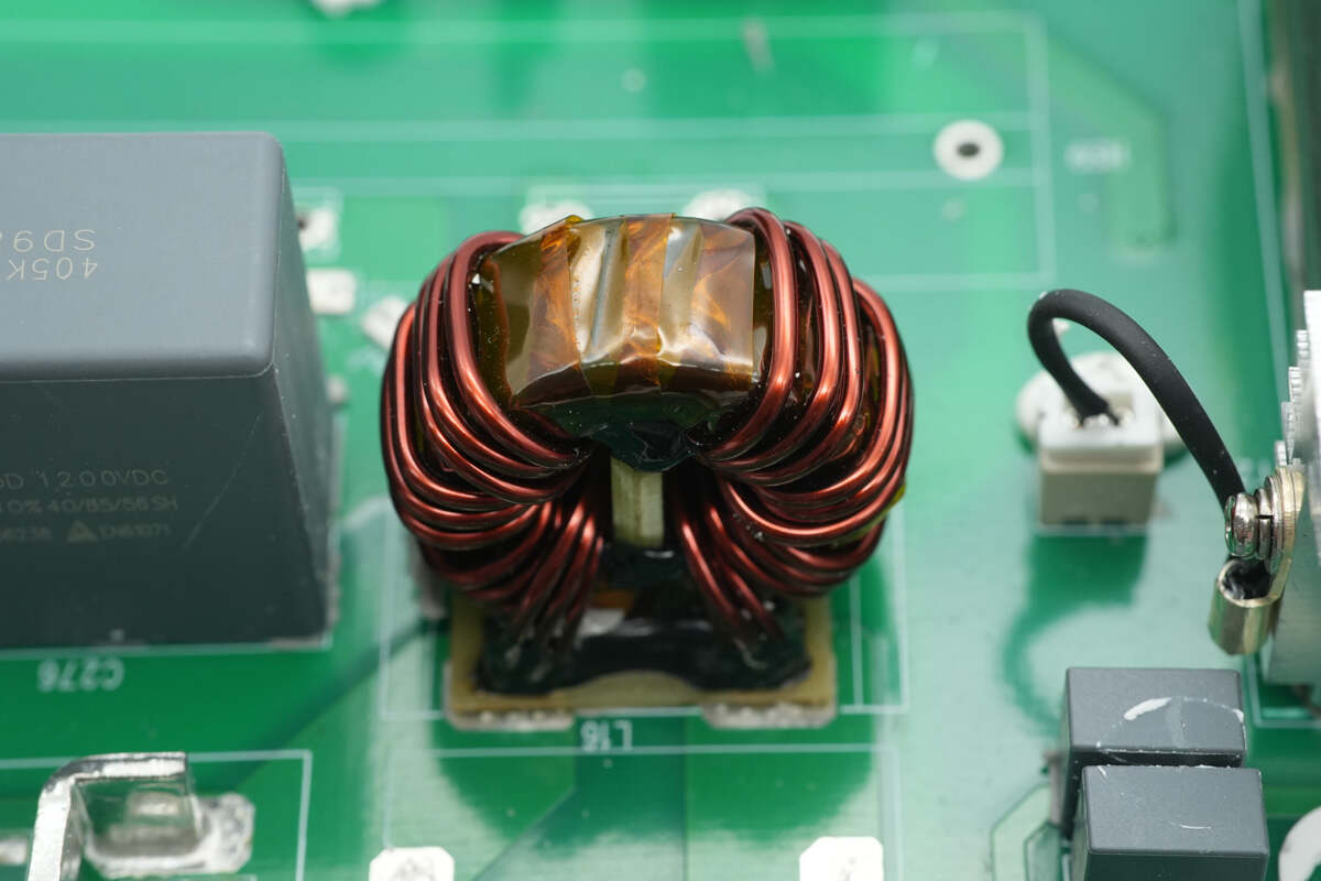
The current transformer used for primary current sensing has a bakelite insulating board at its base.
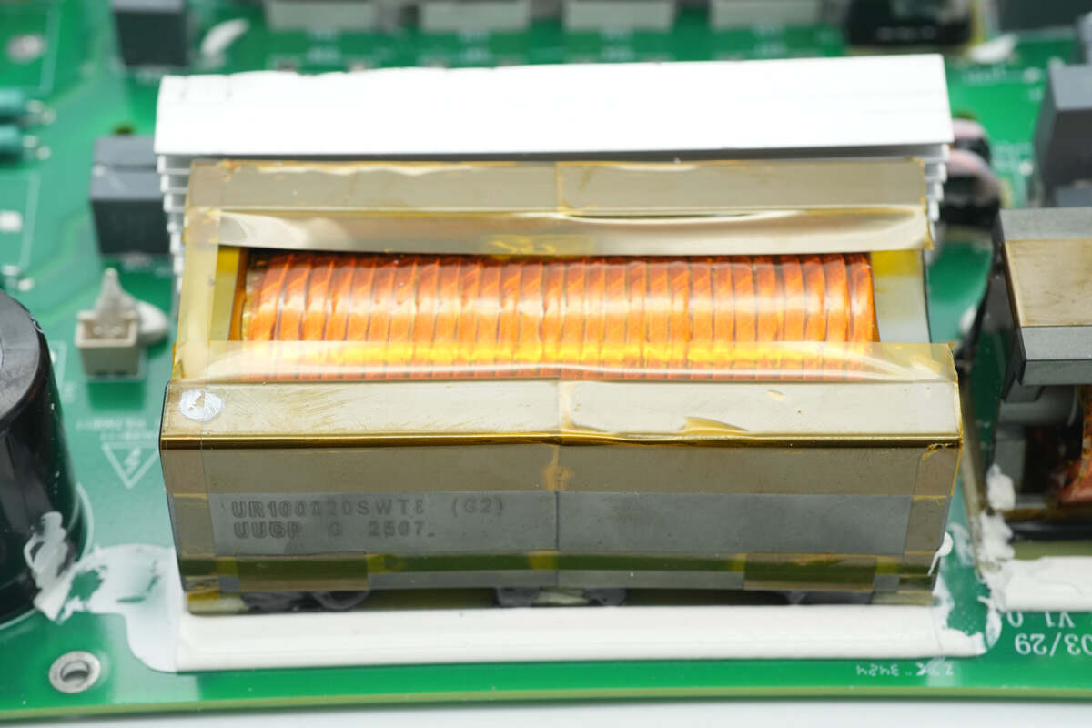
The transformer is wound with Litz wire, and the bottom of the magnetic core is reinforced with adhesive.
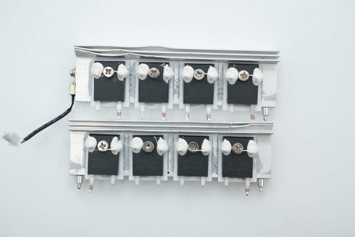
The rectifiers are mounted on the heatsinks.
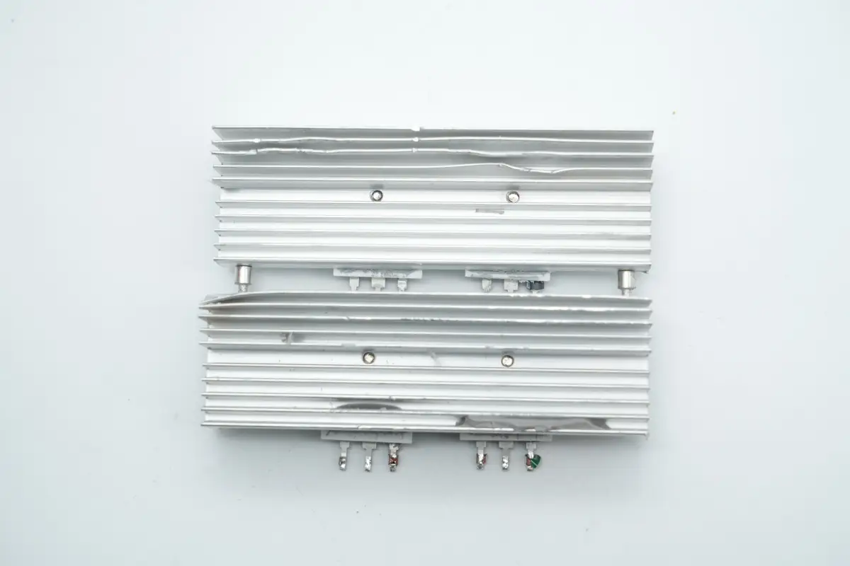
The back of the heatsink features fins to increase the cooling surface area.
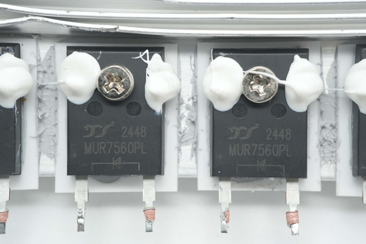
The rectifiers are from YJ, model MUR7560PL. They are ultra-fast recovery diodes rated at 600V and 75A, packaged in TO-247AC.
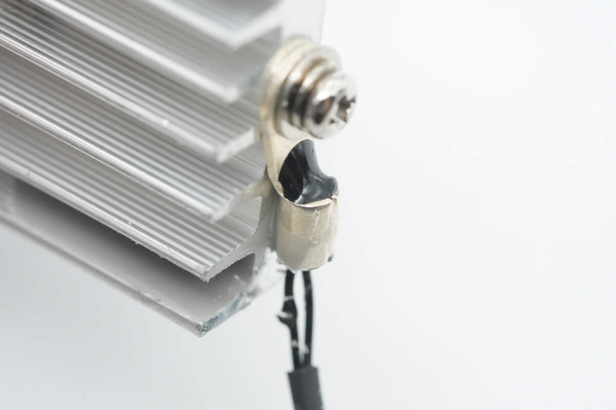
A thermistor is installed on the side of the heatsink to monitor temperature.
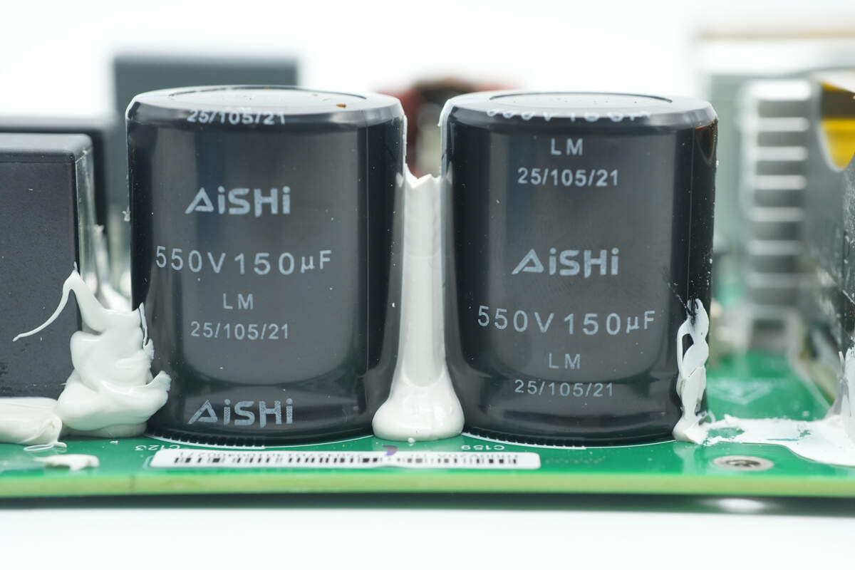
Two output filter capacitors are from AiSHi, rated at 550V 150μF.
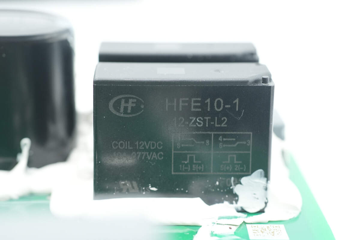
The relay used for output control is from HONGFA, model HFE10-1/12ZST-L2. It is a latching relay with a dual-coil mechanism, a 12V coil voltage, and features a single changeover contact.
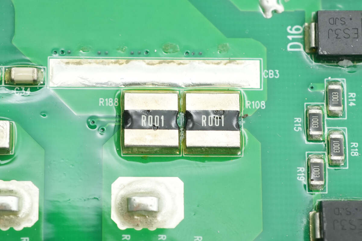
Two 1mΩ resistors are connected in parallel to sense the output current.
The filter inductor is wound with enamel-coated wire.

The film capacitor is from Faratronic, rated at 4μF 1200V.
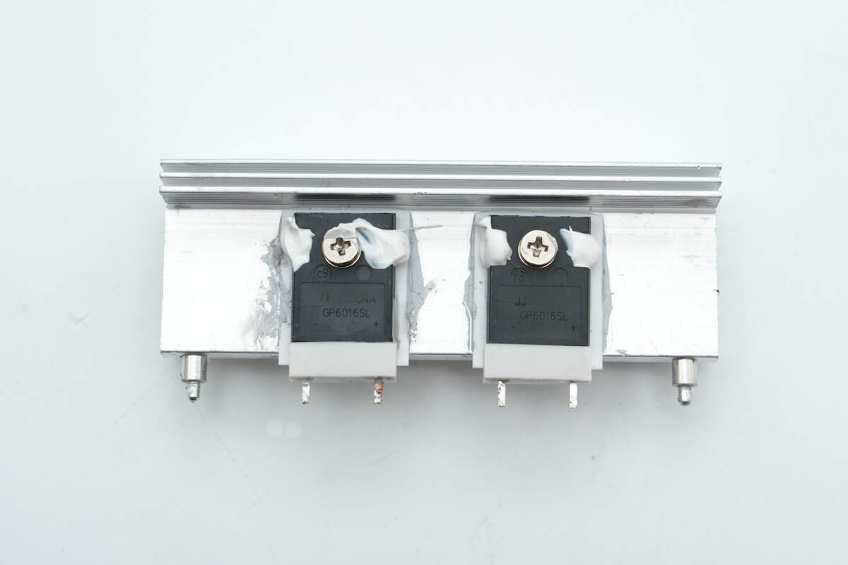
The reverse-blocking diodes are mounted on the heatsink.
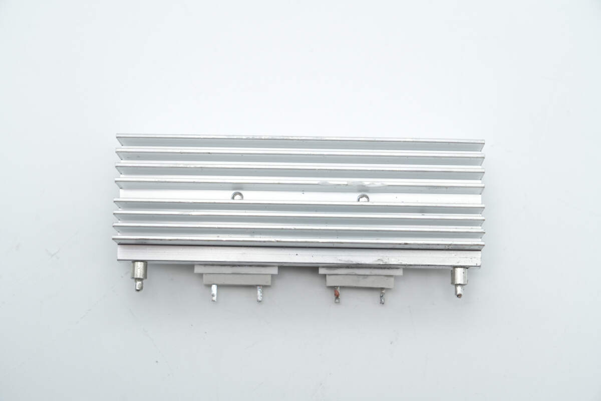
The back of the heatsink features fins to increase the cooling surface area.
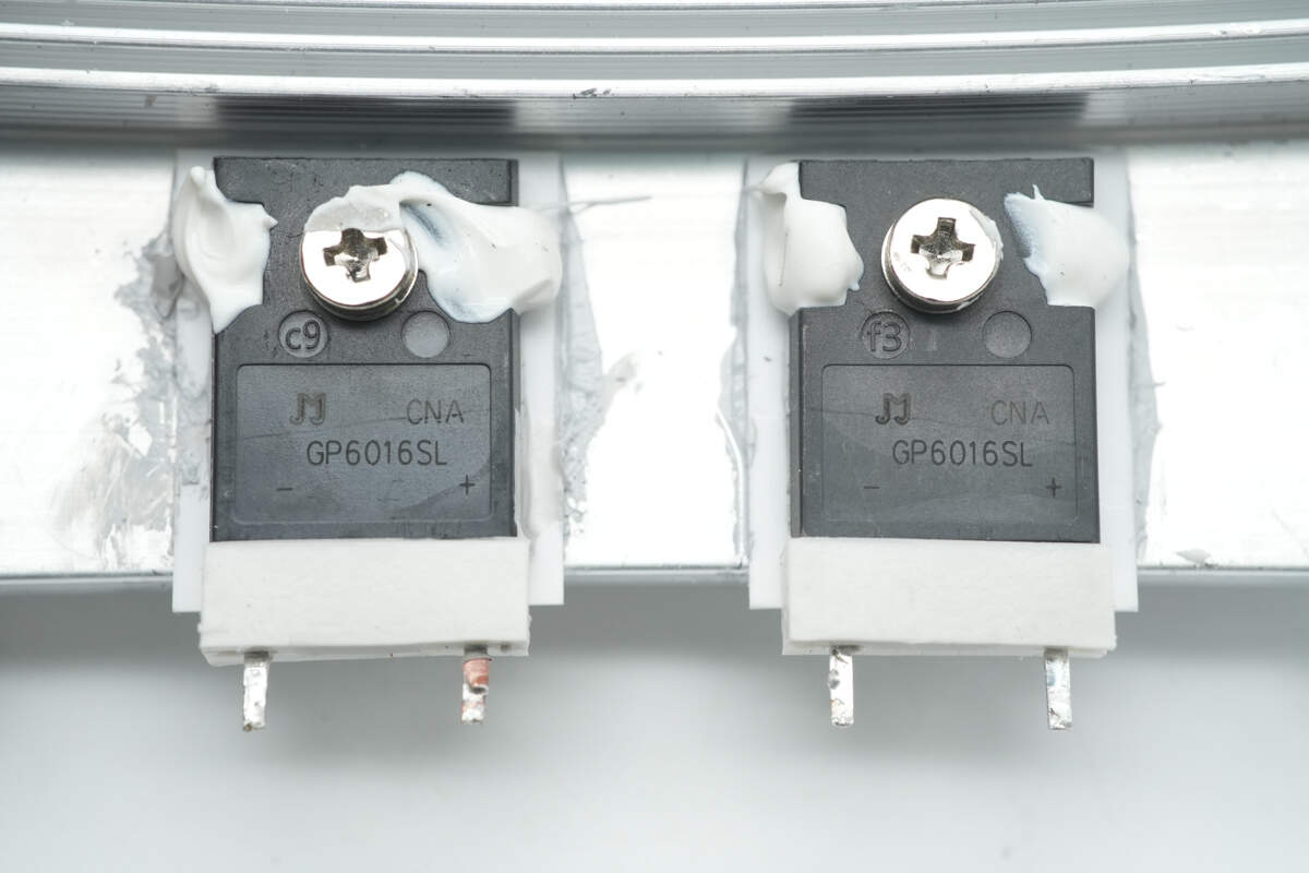
The diodes are from JJWD, model GP6016SL, rated at 1600V and 60A, packaged in TO-247J-2L.
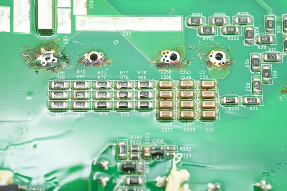
Close-up of the resistor-capacitor snubber circuit located on the back side of the reverse-blocking diodes.
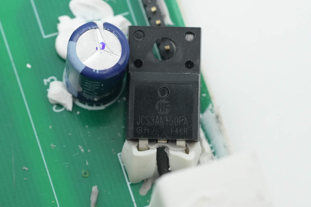
The output discharge transistor is from HWDZ, model JCS3AN150FA. It is an NMOS device rated for 1500V, with an on-resistance of 8Ω, packaged in TO-220MF.
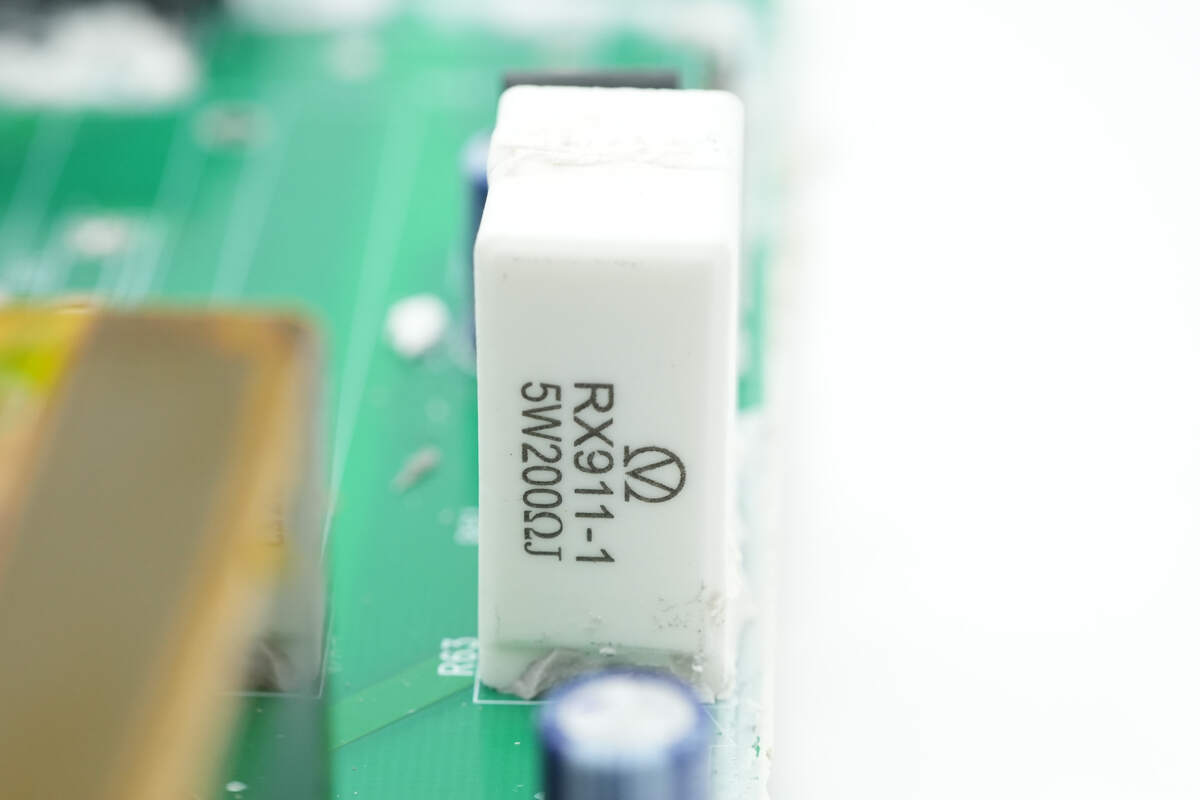
The discharge resistor is from Yongxing, model RX911 wire-wound resistor, rated at 5W and 200Ω.
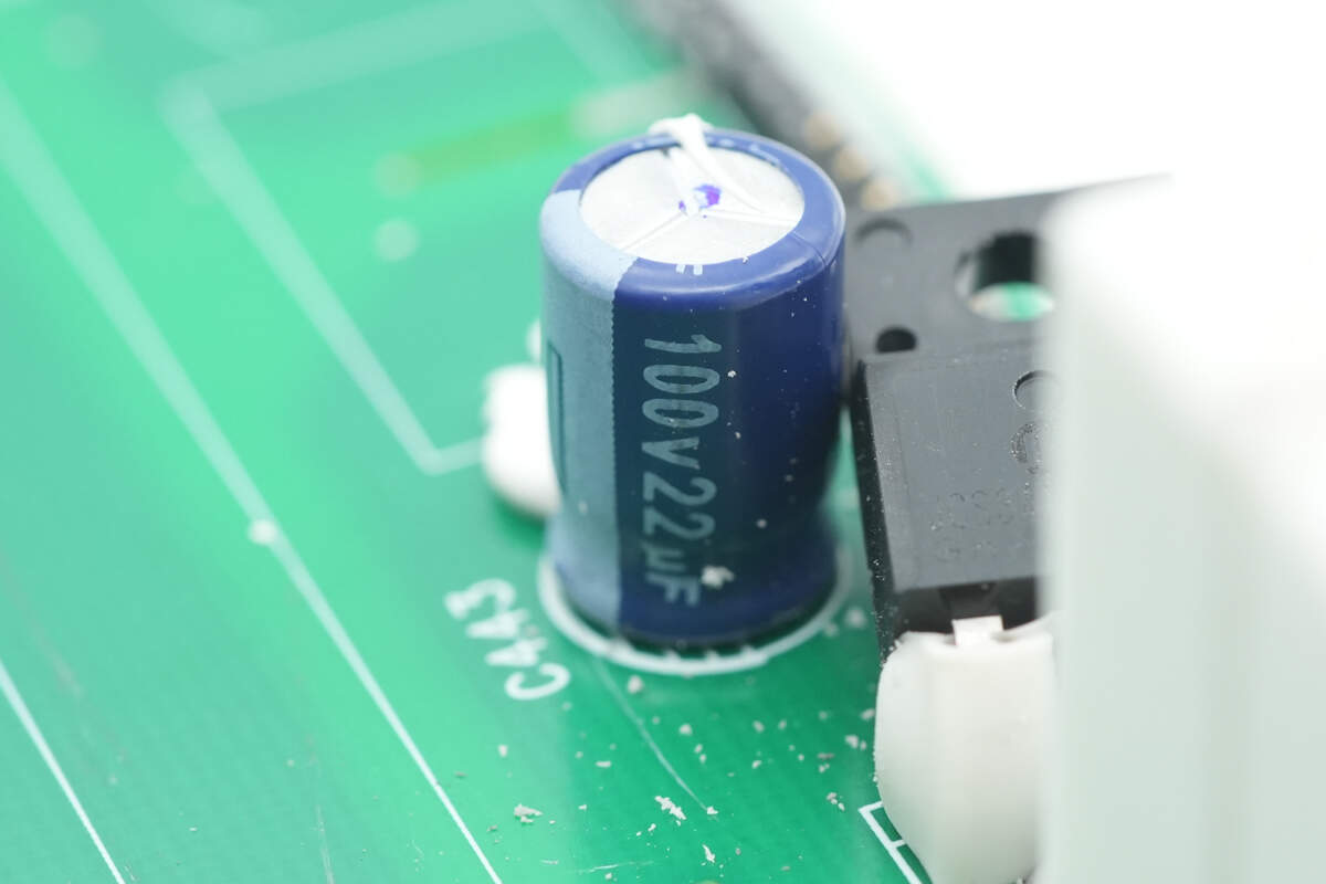
The filter capacitor is rated at 100V and 22μF.
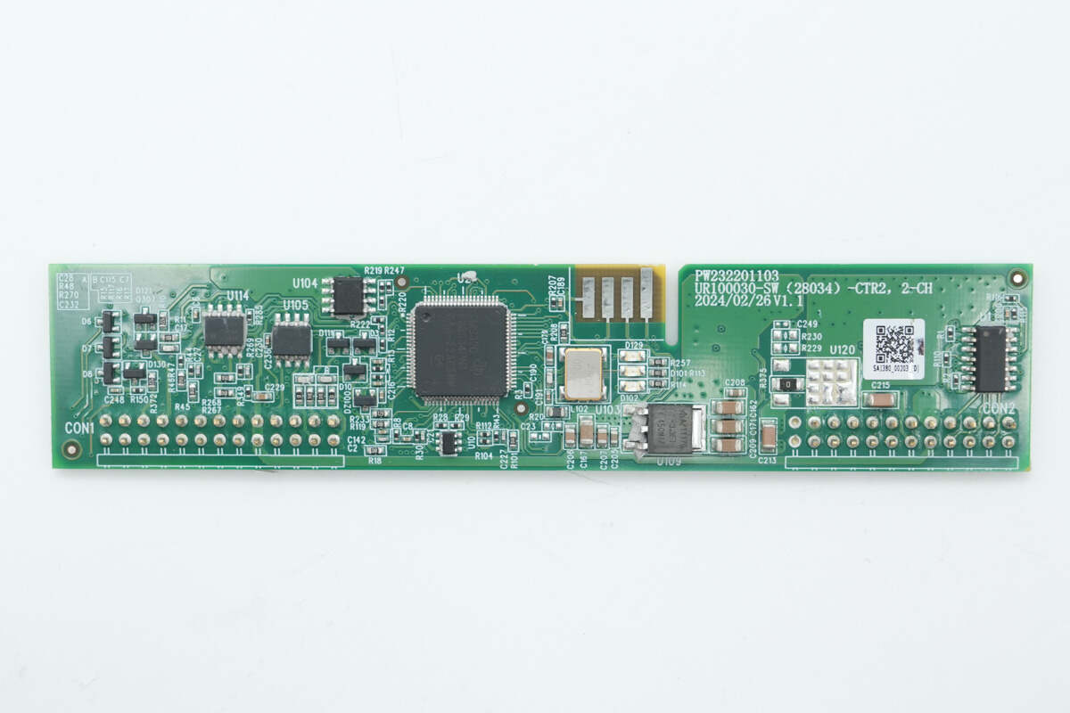
The front side of the control PCB features the LLC controller, memory, operational amplifiers, voltage regulator, and AND gate chip.
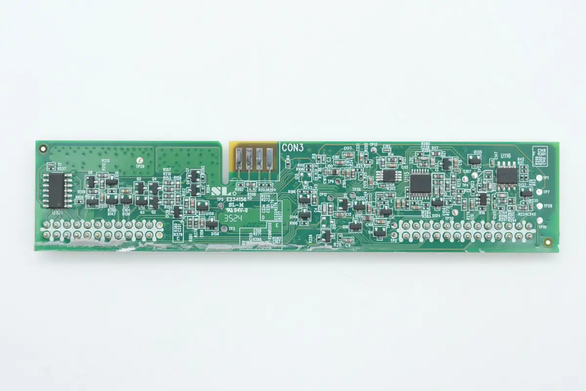
The back side is equipped with operational amplifiers, a voltage comparator, and an AND gate chip.
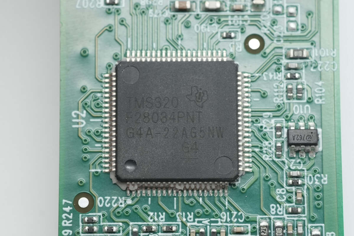
The LLC controller is sourced from TI and belongs to the C2000 series of real-time microcontrollers. The specific model is TMS320F28034PNT, featuring a 32-bit CPU core with a 60 MHz operating frequency. It supports coordinated operations, fast interrupt response and processing, and integrates 128 KB of flash memory. Typical applications include outdoor air conditioning units, DC-DC converters, inverters and motor control, on-board chargers, charging stations, and BLDC motor drives. It comes in an LQFP80 package.
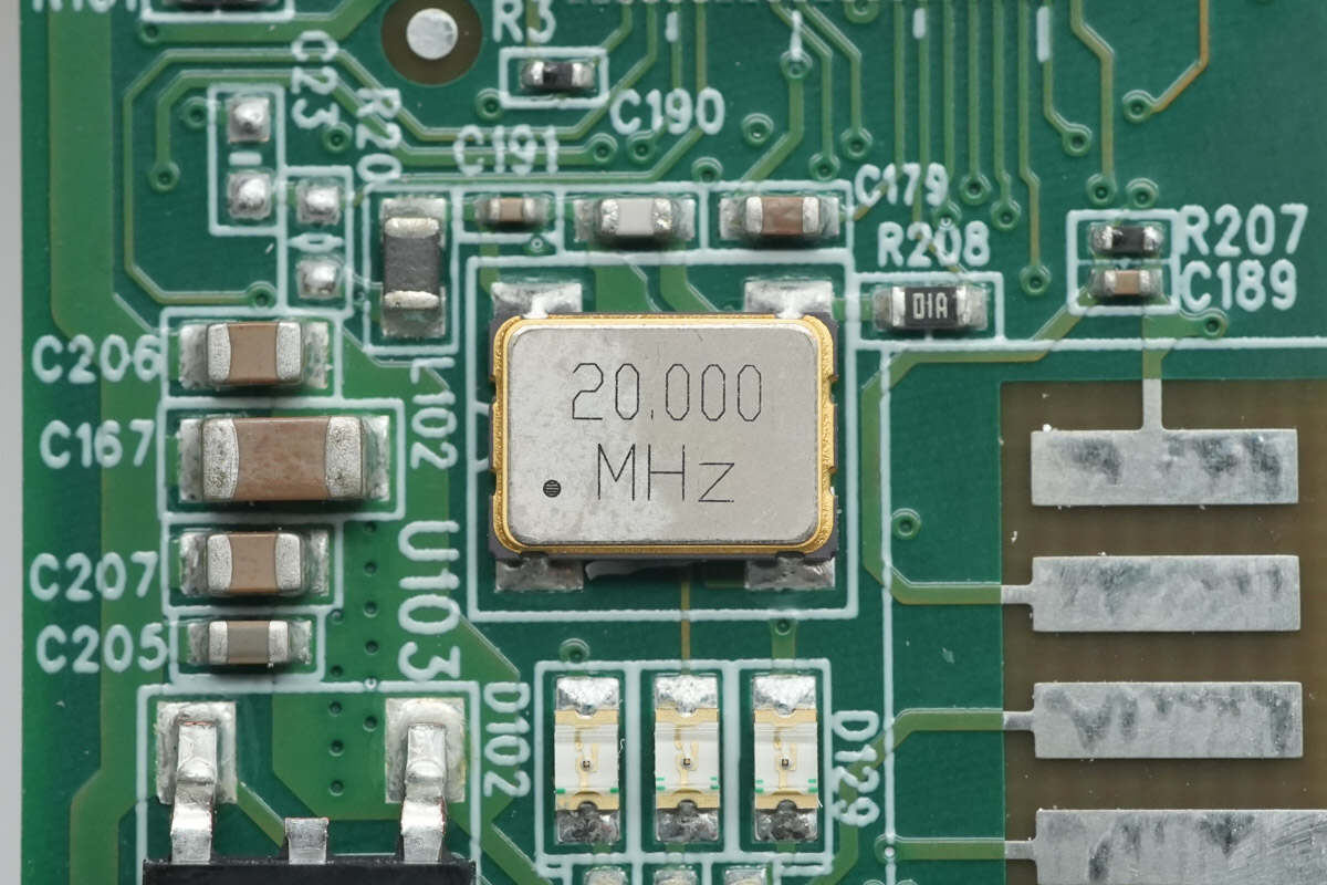
Close-up of the 20.000MHz clock crystal oscillator.
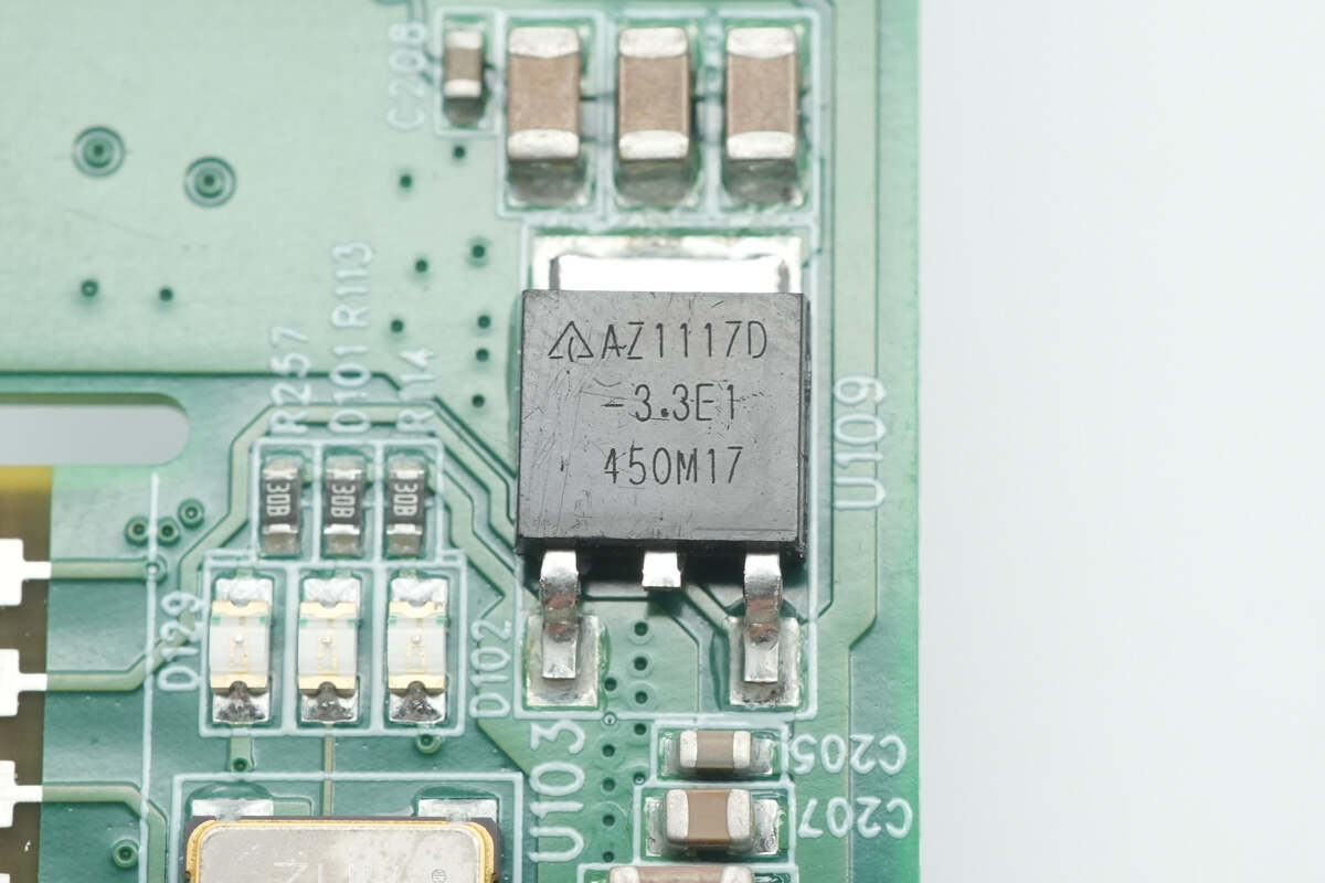
The voltage regulator is from DIODES, model AZ1117D-3.3TRE1, and the output voltage is 3.3V.
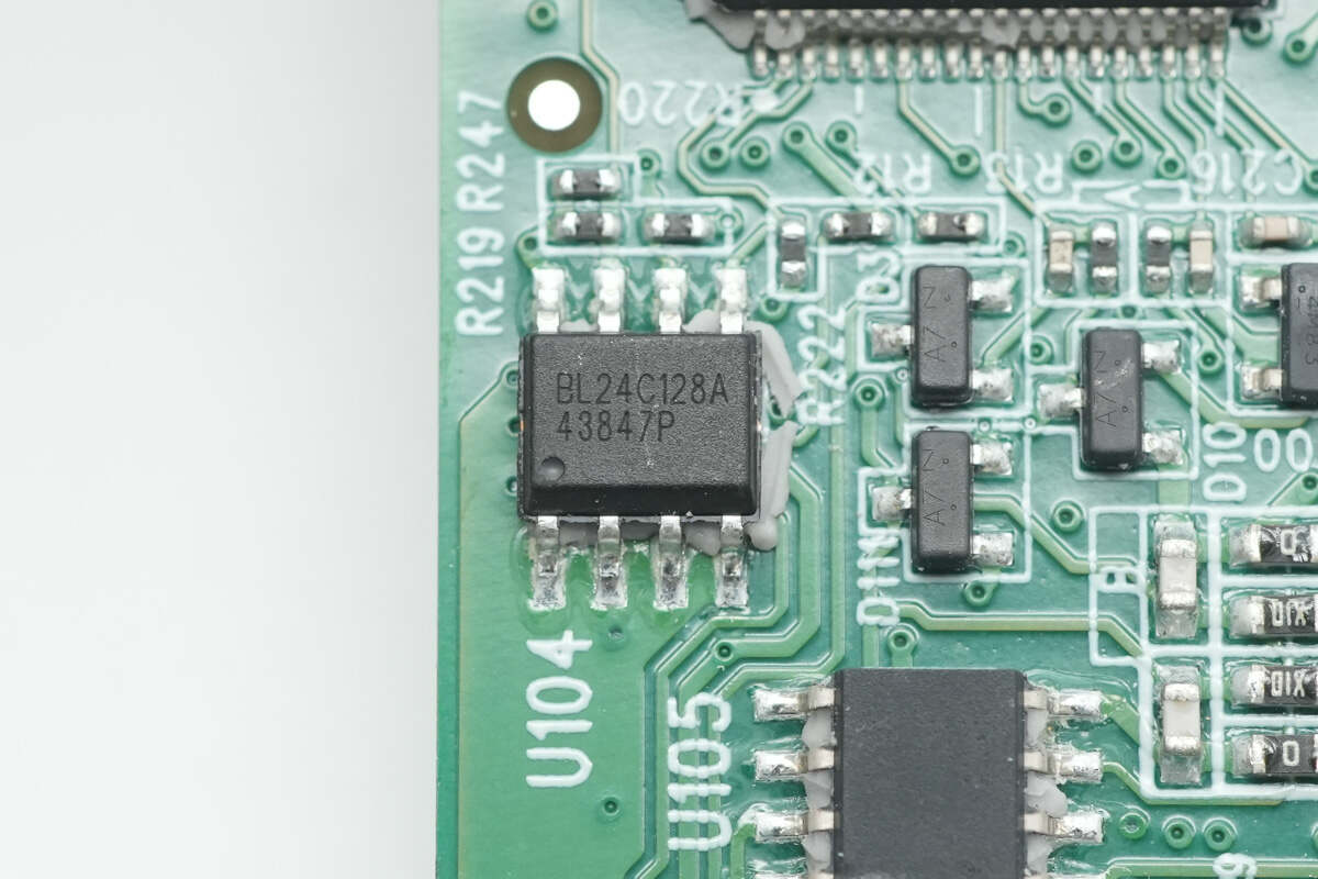
The memory comes from Belling, model BL24C128A, has a capacity of 16KB, supports 1.7-5.5V operating voltage, and uses SOP8 package.
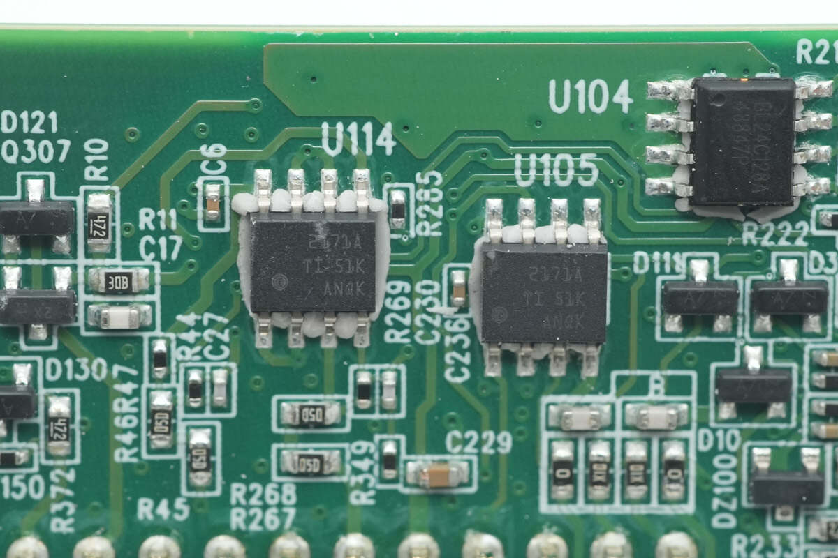
Two operational amplifiers are sourced from Texas Instruments, model OPA2171. These are dual low-power operational amplifiers that support a supply voltage of up to 36 V and come in an SOIC-8 package.
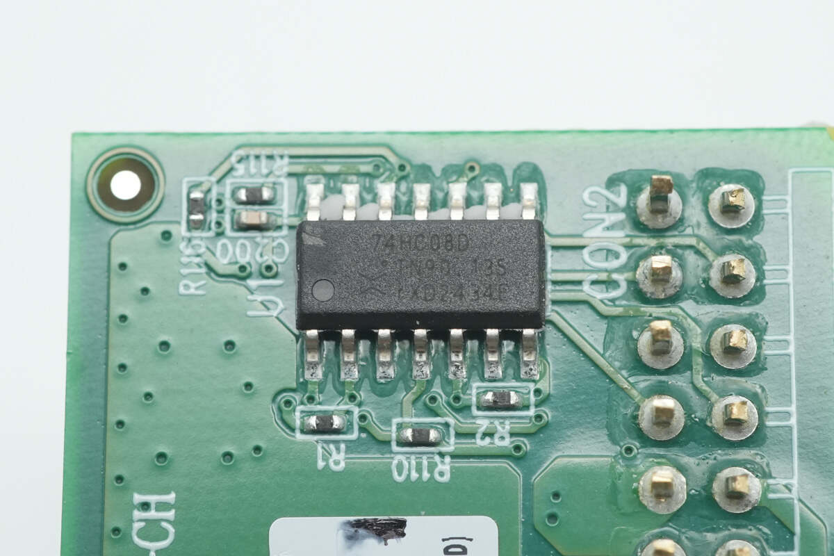
The AND gate chip is from Nexperia, model 74HC08D.
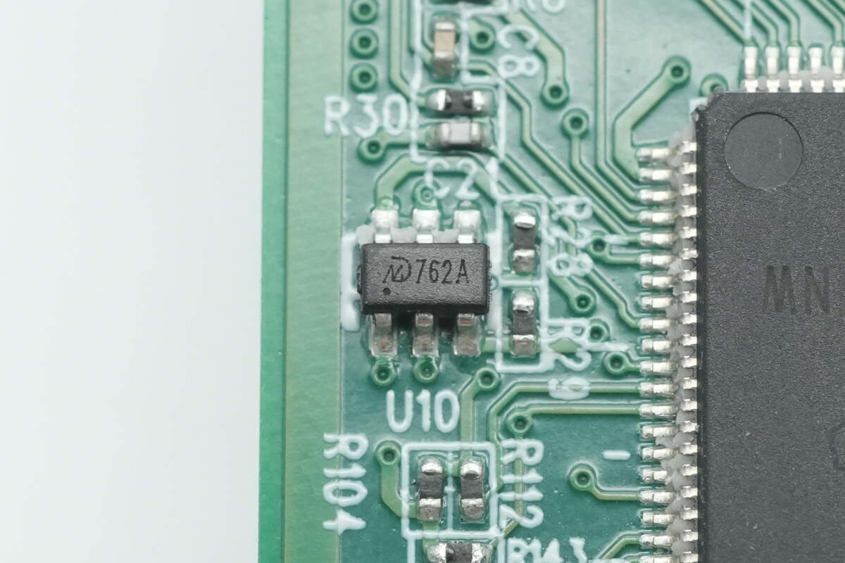
The relay driver chip is sourced from MD, model MD7620A. It is a bidirectional latching relay driver with a maximum drive current of 800 mA. The chip integrates freewheeling diodes internally and comes in an SOT23-6 package.
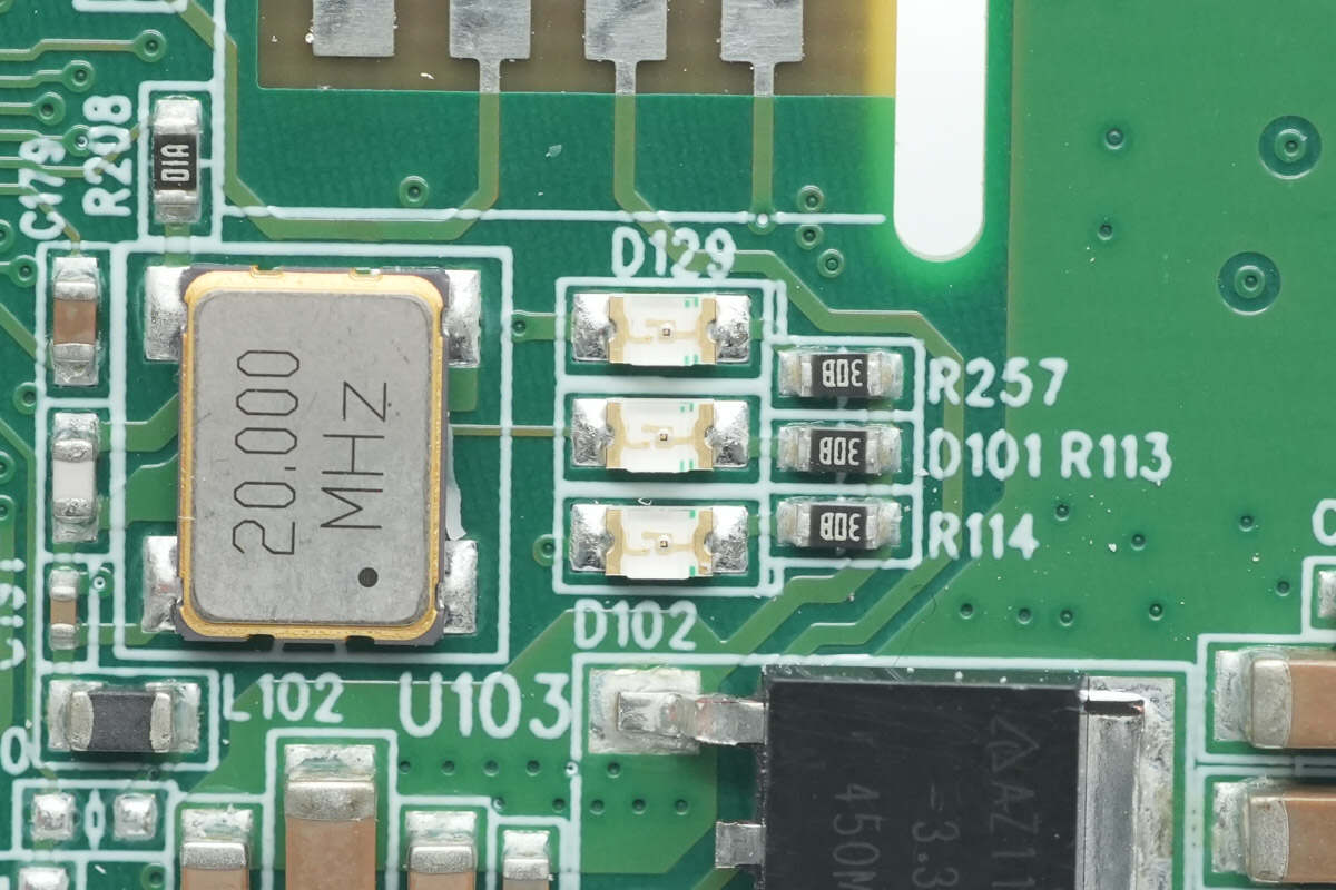
Close-up of SMD LED indicators.
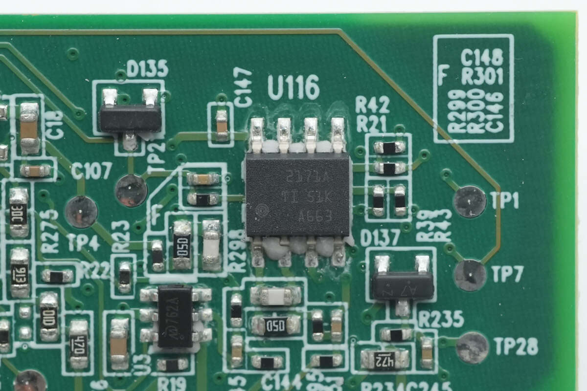
On the back side, there is a Texas Instruments OPA2171 dual operational amplifier.

Close-up of the MD MD7620A driver chip.
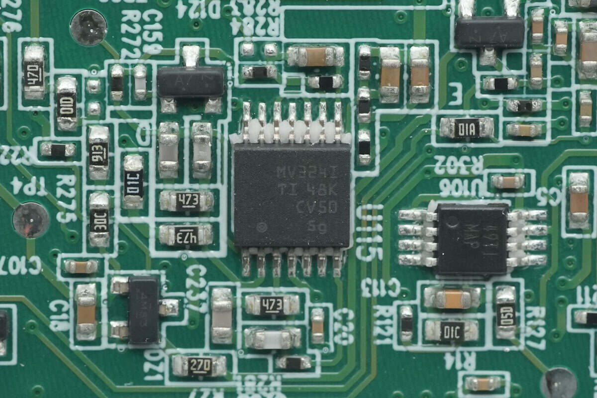
The operational amplifier is sourced from Texas Instruments, model LMV324. It is a quad-channel operational amplifier in a TSSOP-14 package.
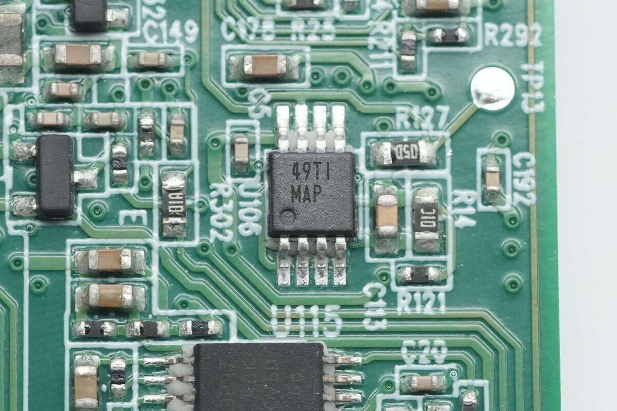
The voltage comparator is from Texas Instruments, marked with MAP, model LM2903.
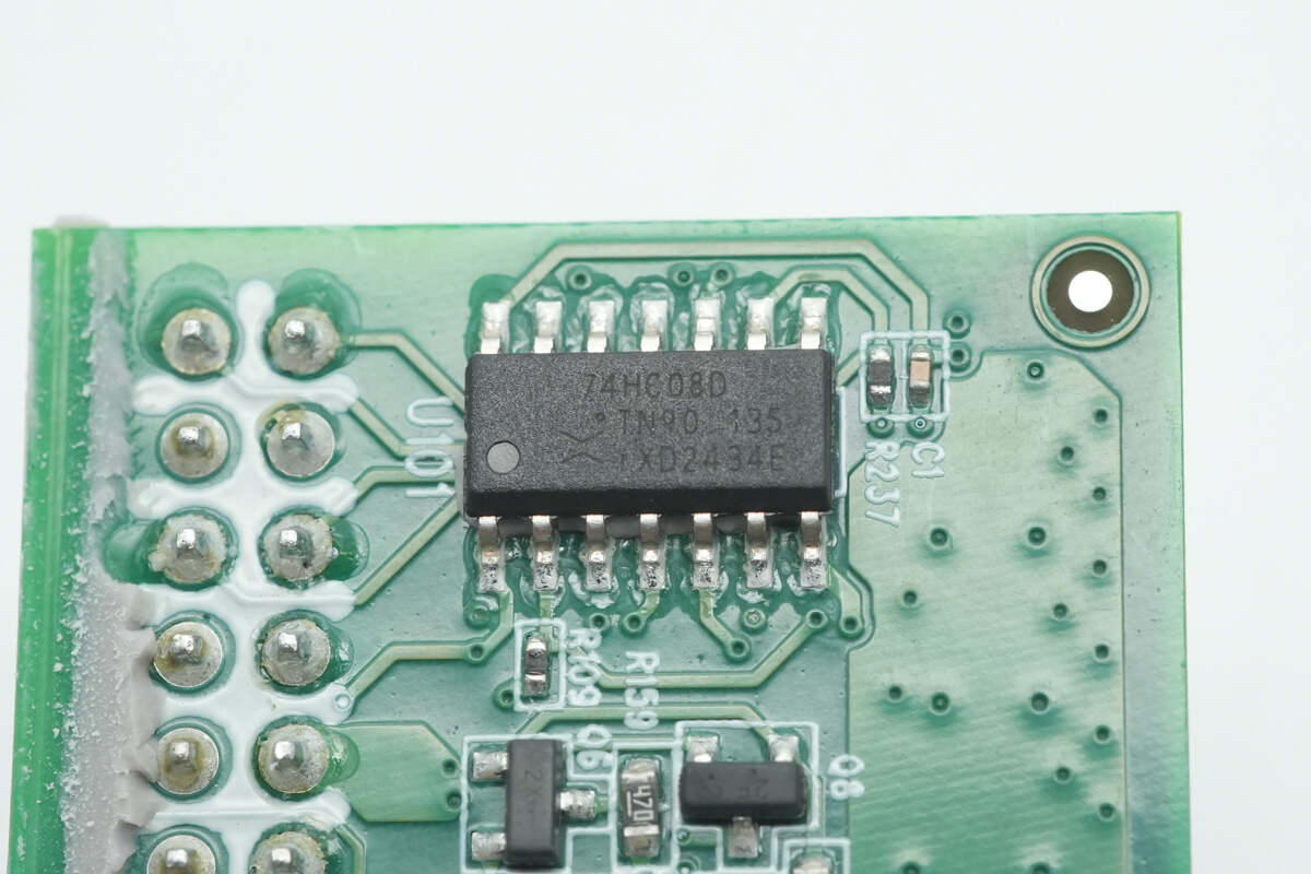
The AND gate chip is from Nexperia, model 74HC08D.
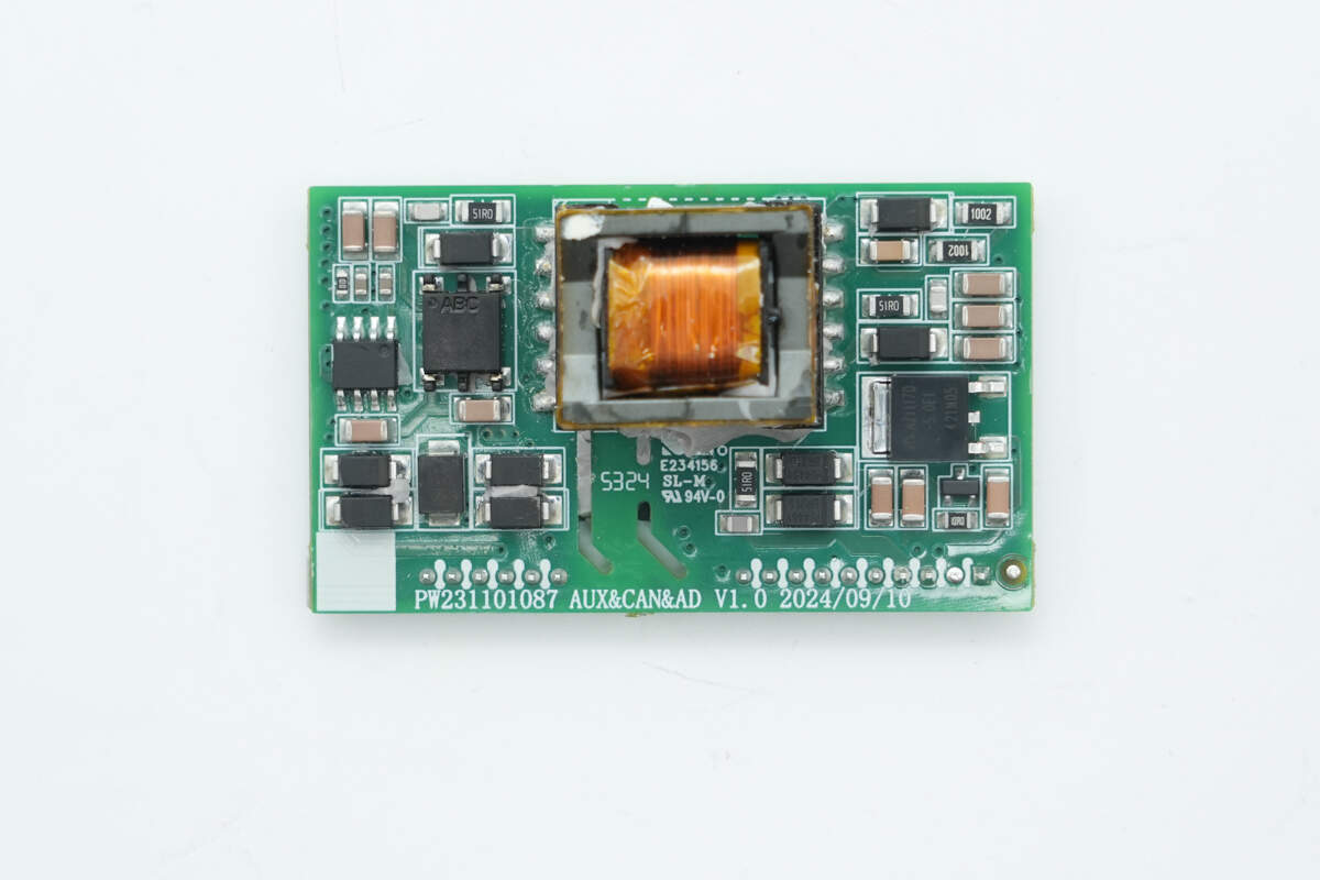
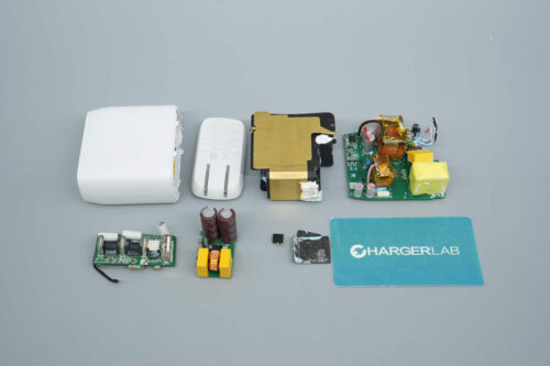
The front side of the auxiliary power and isolated communication PCB features a transformer and voltage regulator chips.
The back side houses the master control chip, primary MOSFETs, and isolation chips.
The master control chip is from Texas Instruments, model UCC28C45.
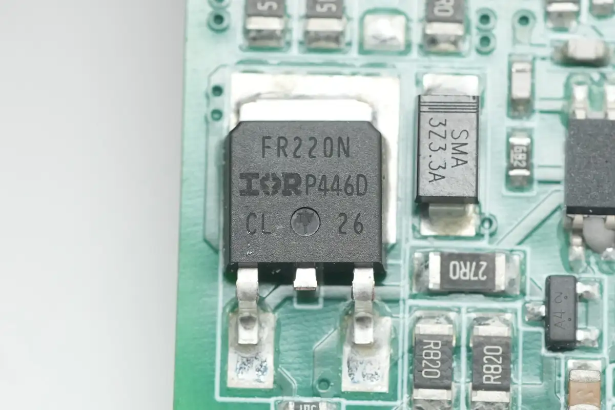
The MOSFET is from Infineon, model IRFR220N, NMOS, with a withstand voltage of 200V, a resistance of 600mΩ, and uses a D-PAK package.
The transformer coils are insulated with high-temperature adhesive tape.
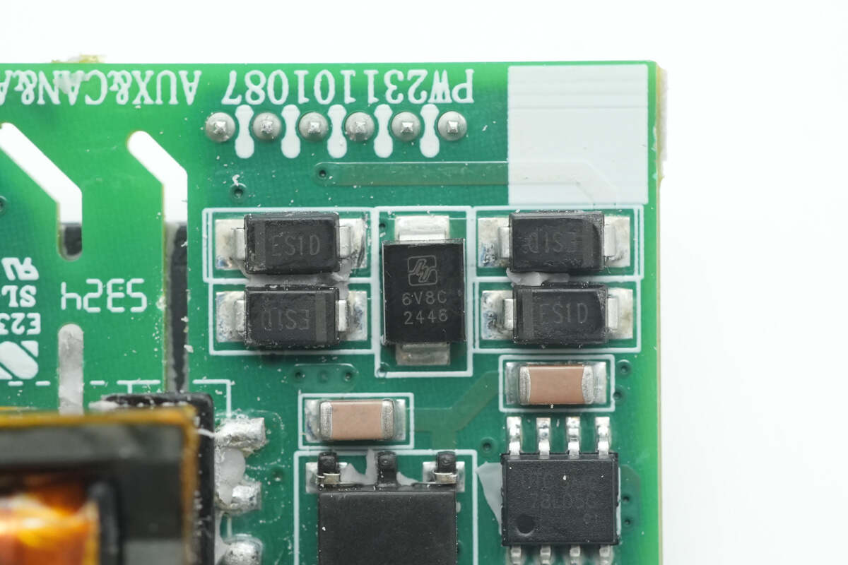
Close-up of the rectifier and the voltage regulator.
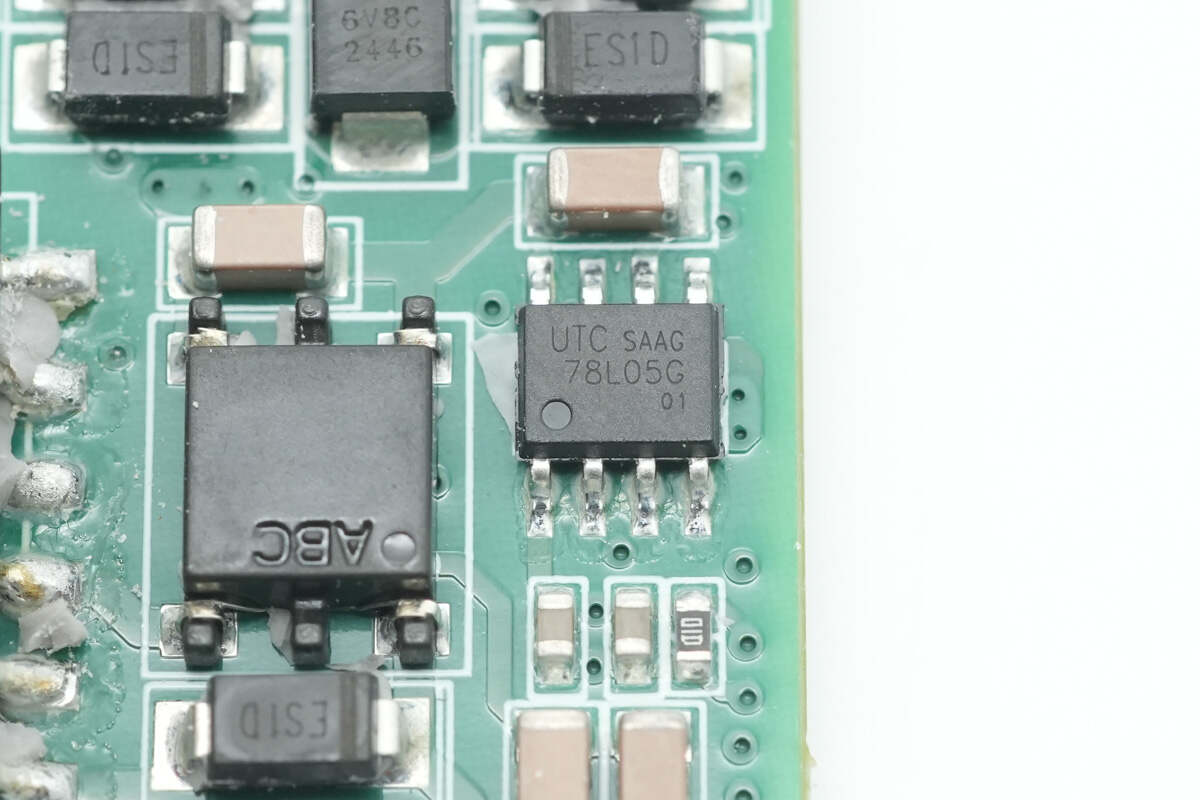
The voltage regulator chip is from Unisonic, model UTC78L05G.
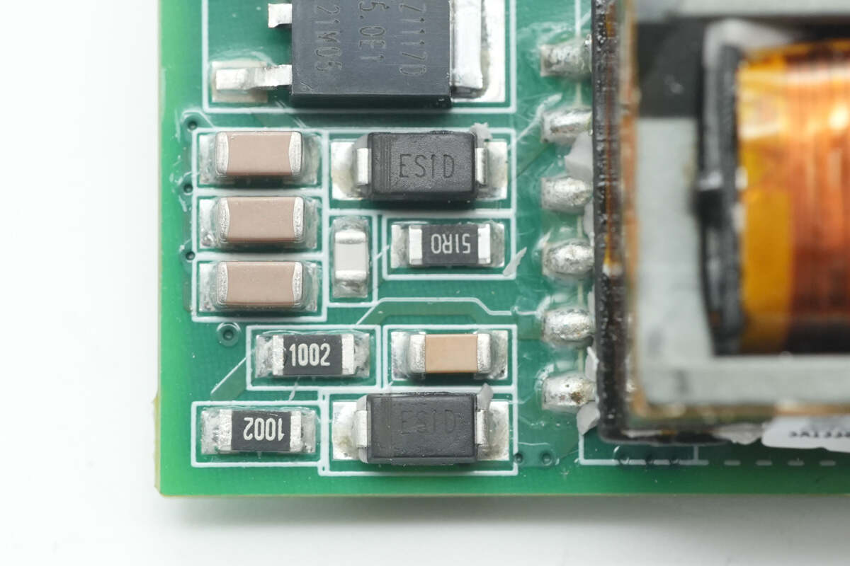
Close-up of two rectifiers.
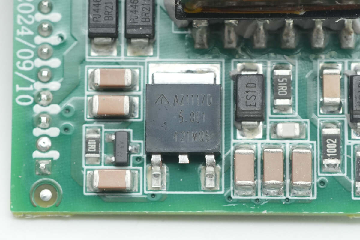
The voltage regulator chip is from DIODES, model AZ1117D-5.0TRE1.
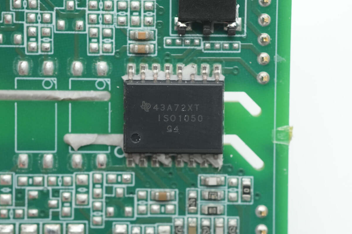
The isolated communication chip is sourced from Texas Instruments, model ISO1050. It is an isolated CAN bus transceiver compliant with the ISO11898-2 standard, supporting both 3.3 V and 5 V I/O voltages. It comes in an SOIC-16 package.
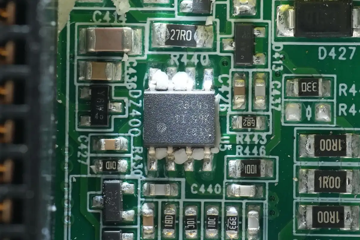
The master control chip is from Texas Instruments, model UCC28C45.
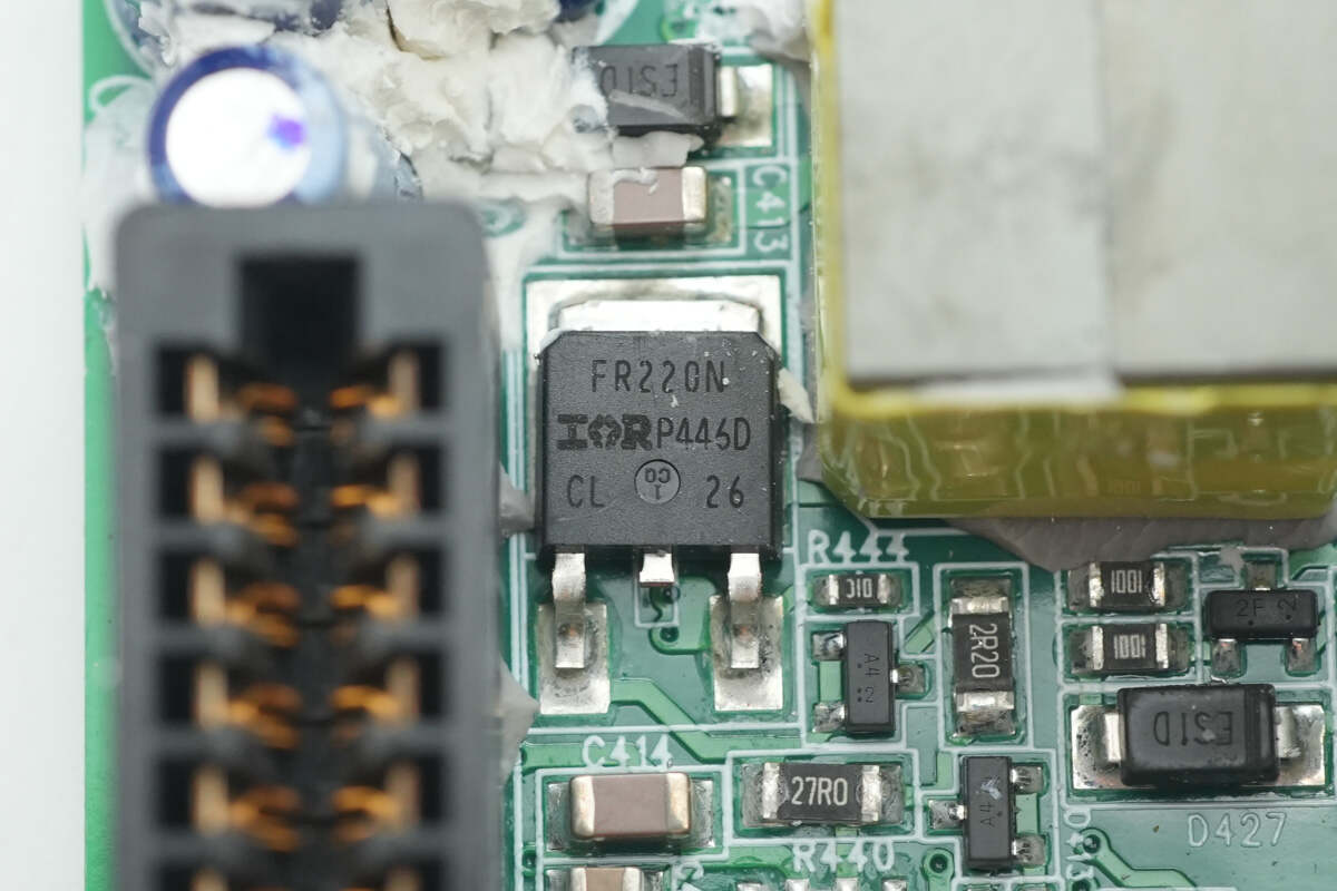
The MOSFET is from Infineon, model IRFR220N.
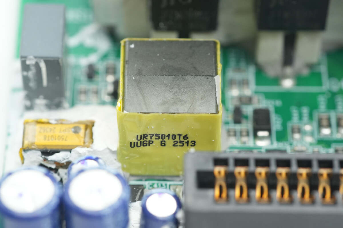
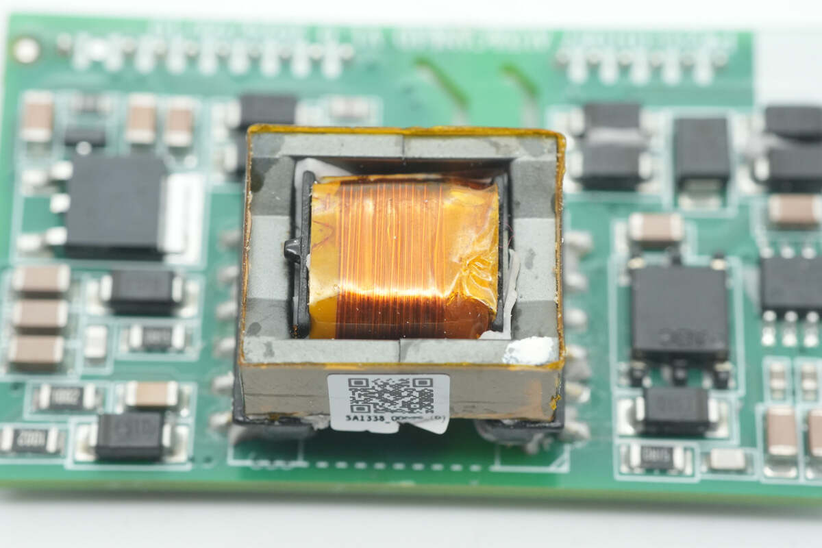
The transformer core is wrapped with insulating tape.

The two MOSFETs are from JIAENSEMI, model JFFM7N90C, NMOS, with a withstand voltage of 900V, a resistance of 1.65Ω, and are packaged in TO-220F.
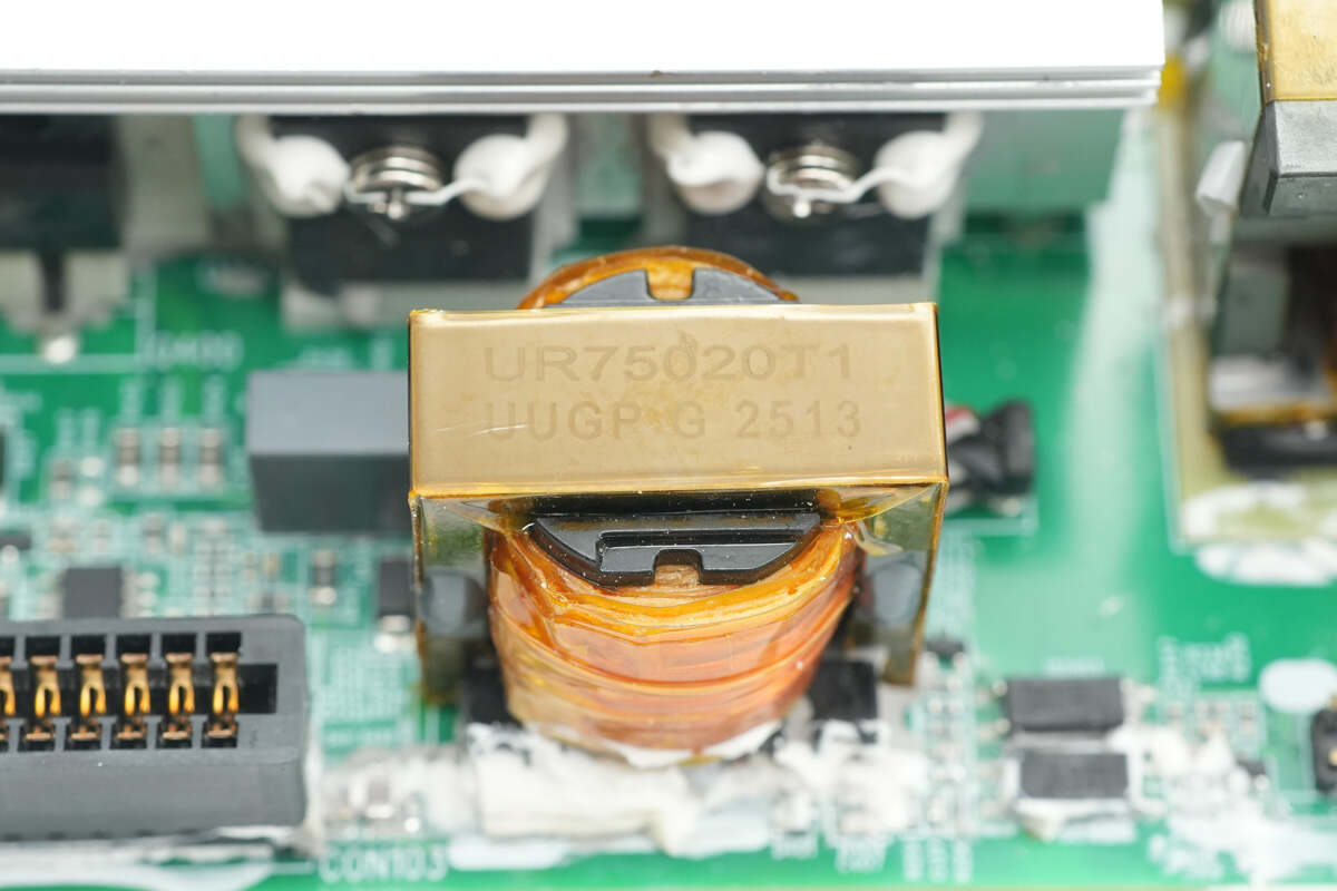
Another transformer core is wrapped with insulation tape.
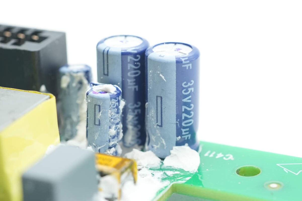
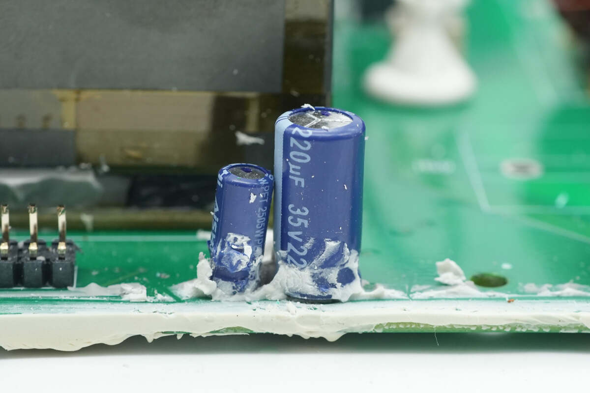
The specifications of the two filter capacitors are 35V 220μF.
The third filter capacitor has a specification of 25V 47μF.
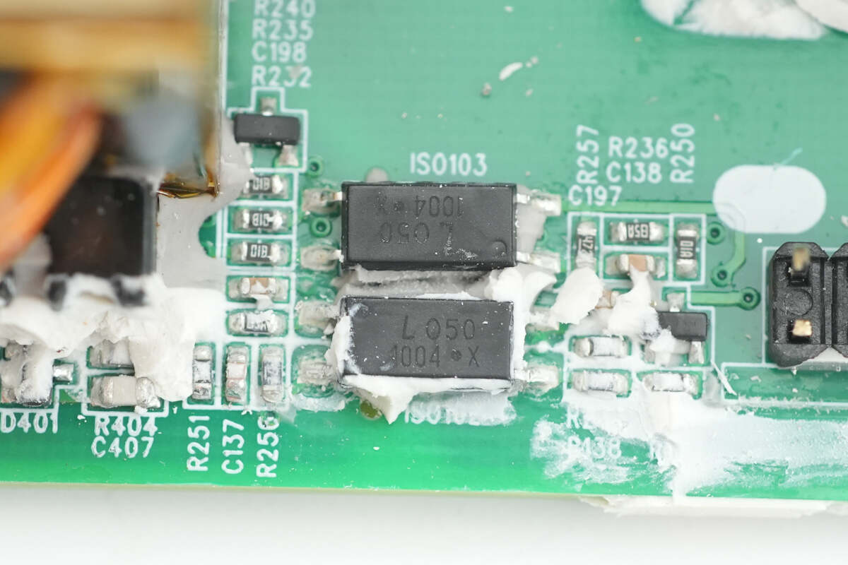
Close-up of the LITEON LTV-1004 optocoupler.
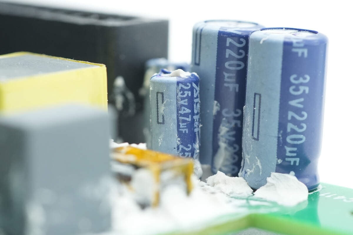
The filter capacitor specification is 35V 220μF.
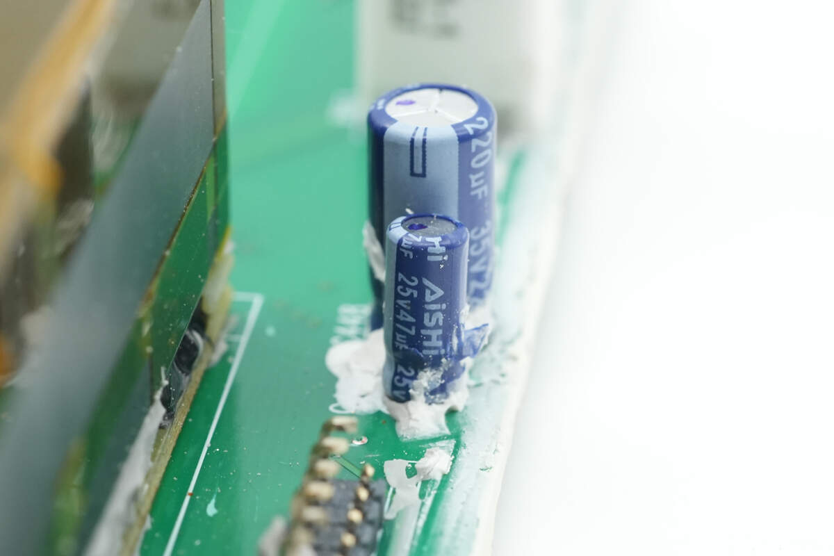
The other filter capacitor specification is 25V 47μF.
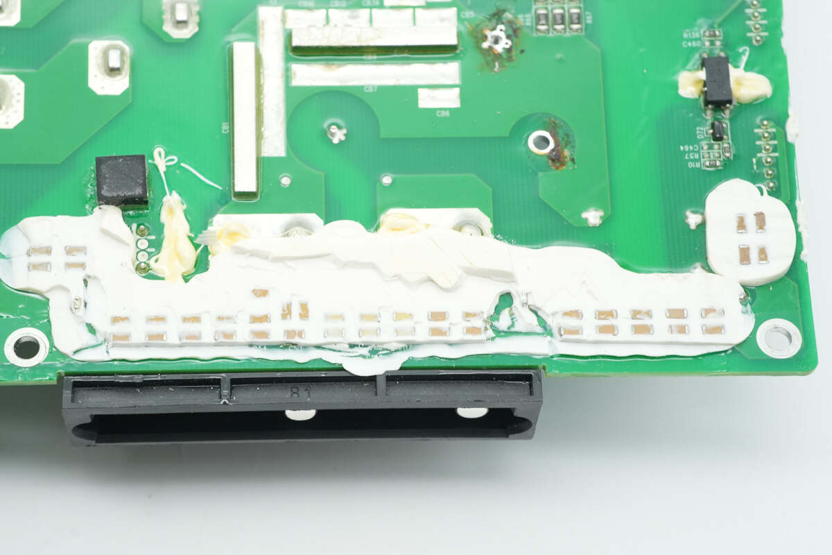
Near the output socket, MLCC filter capacitors are installed and secured with adhesive for protection.
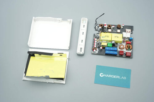
The small PCB is fixed with screws.
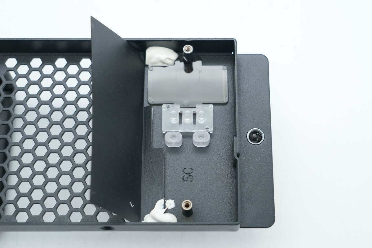
The interior of the casing features a light-transmitting window.
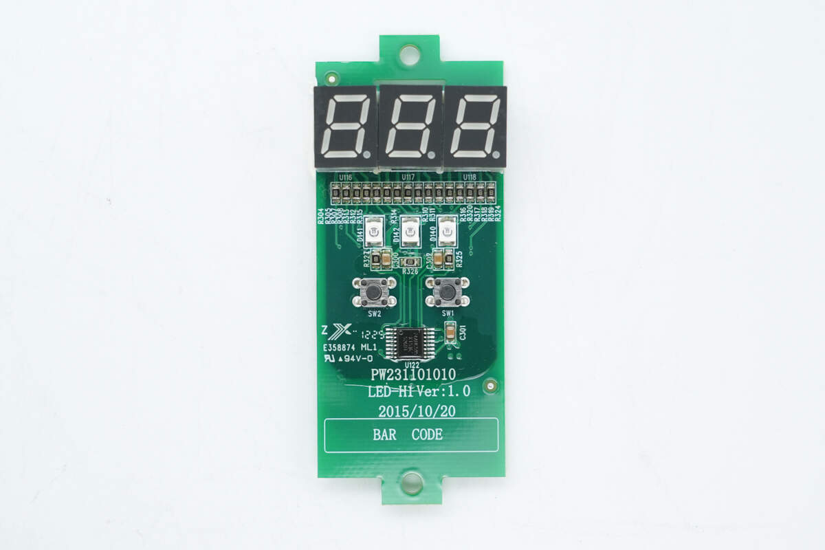
The front side of the small PCB is equipped with three LED numeric displays, three LED indicators, two buttons, and one shift register.
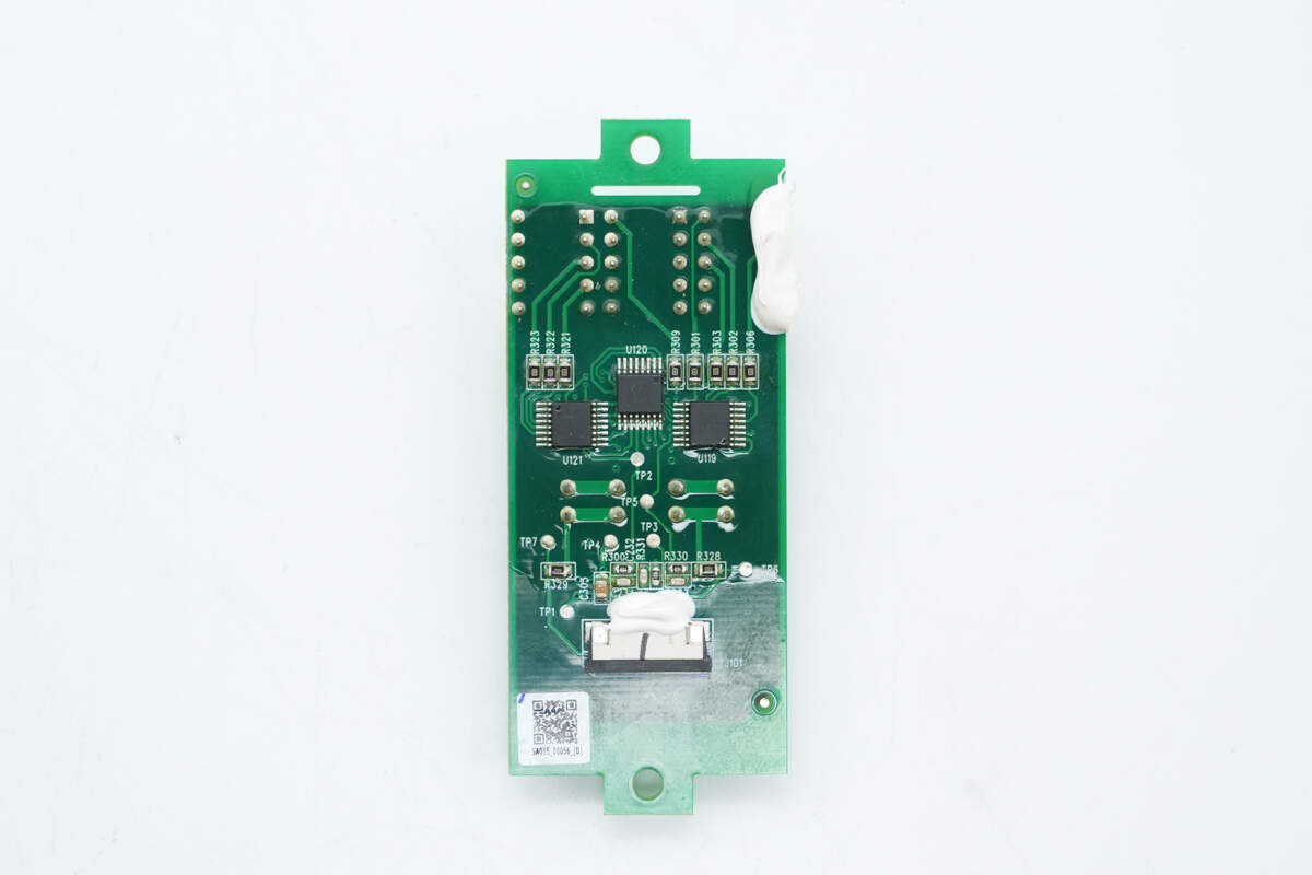
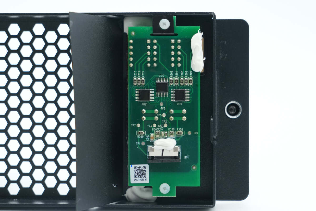
The back side houses three shift registers.
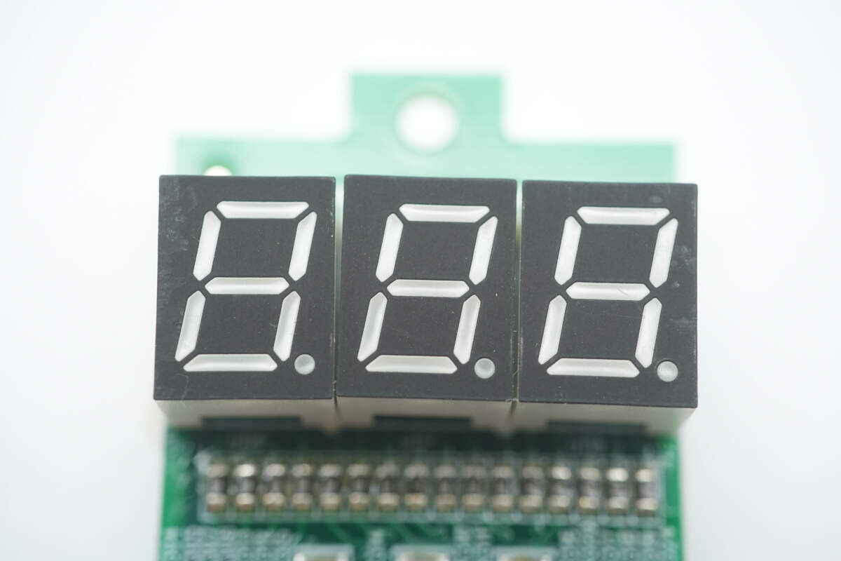
Close-up of the three LED numeric displays.
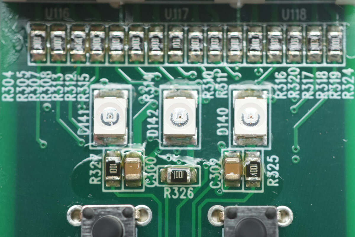
There are three SMD LEDs at the bottom.
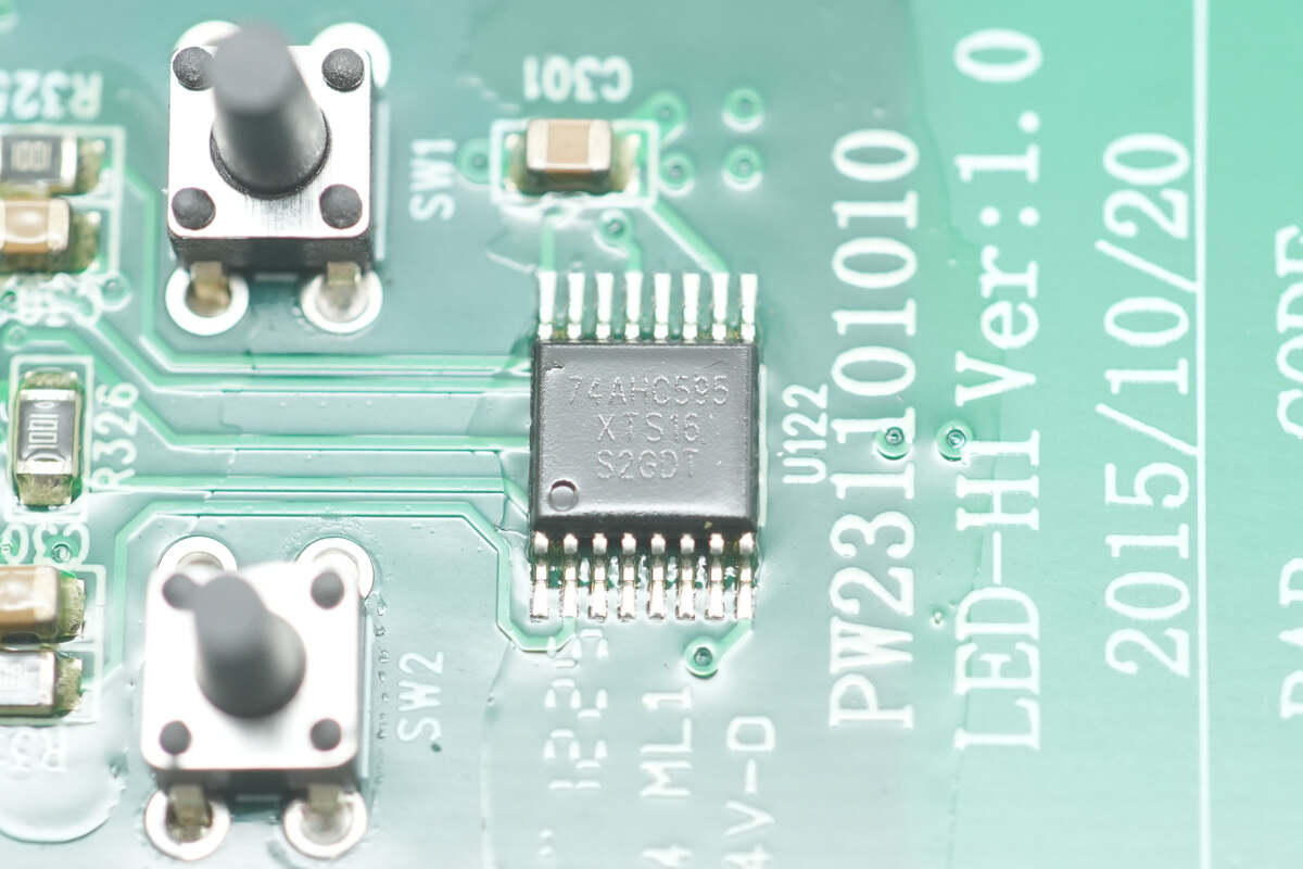
The shift register is from SGMICRO, model 74AHC595. This is an 8-bit serial-in, serial or parallel-out shift register with an output latch, housed in a TSSOP-16 package.
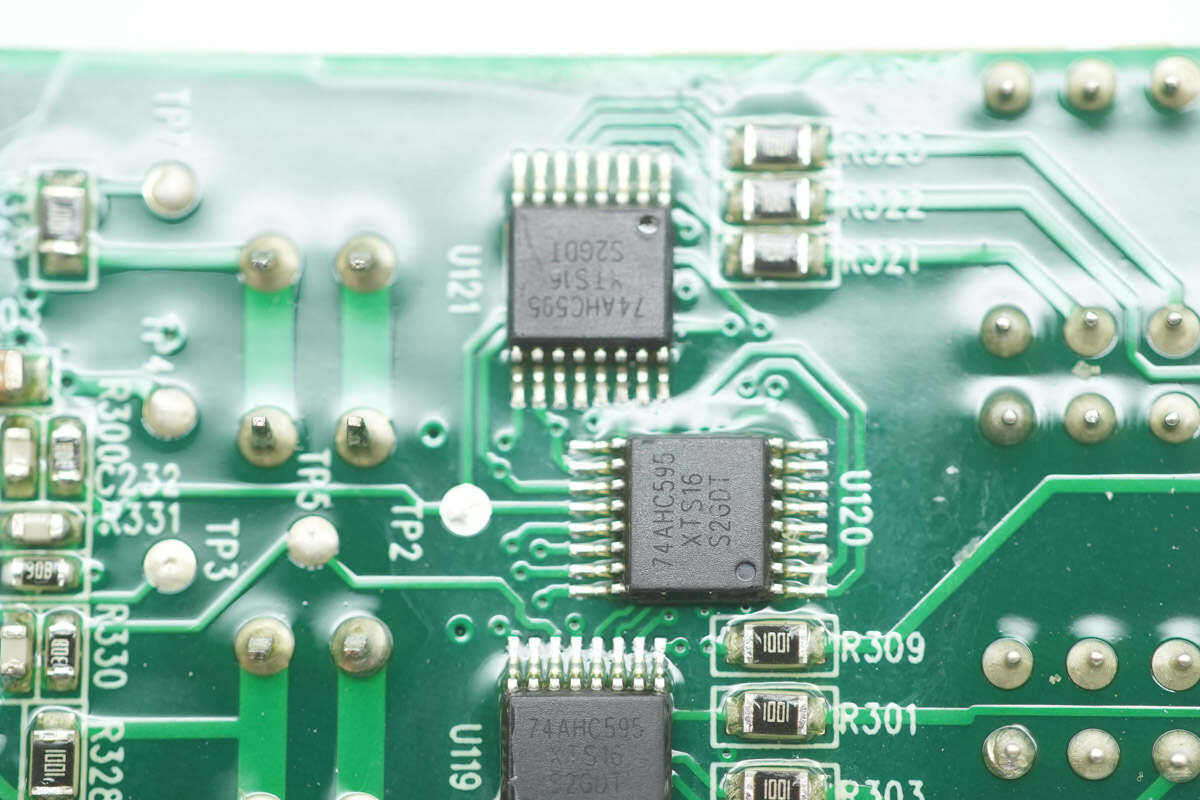
The three shift registers on the back side are of the same model.
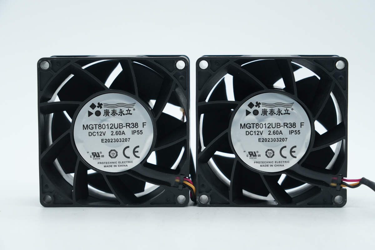
The cooling fans' model is MGT8012UB-R38, with specifications of 12V 2.6A and IP55 protection.
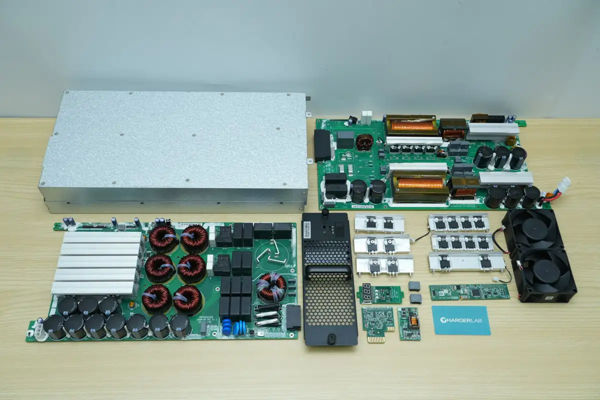
Well, those are all components of the UUGreenPower UR100020‑SW 20 kW Ultra‑Wide Voltage Constant Power Charging Module.
Summary of ChargerLAB
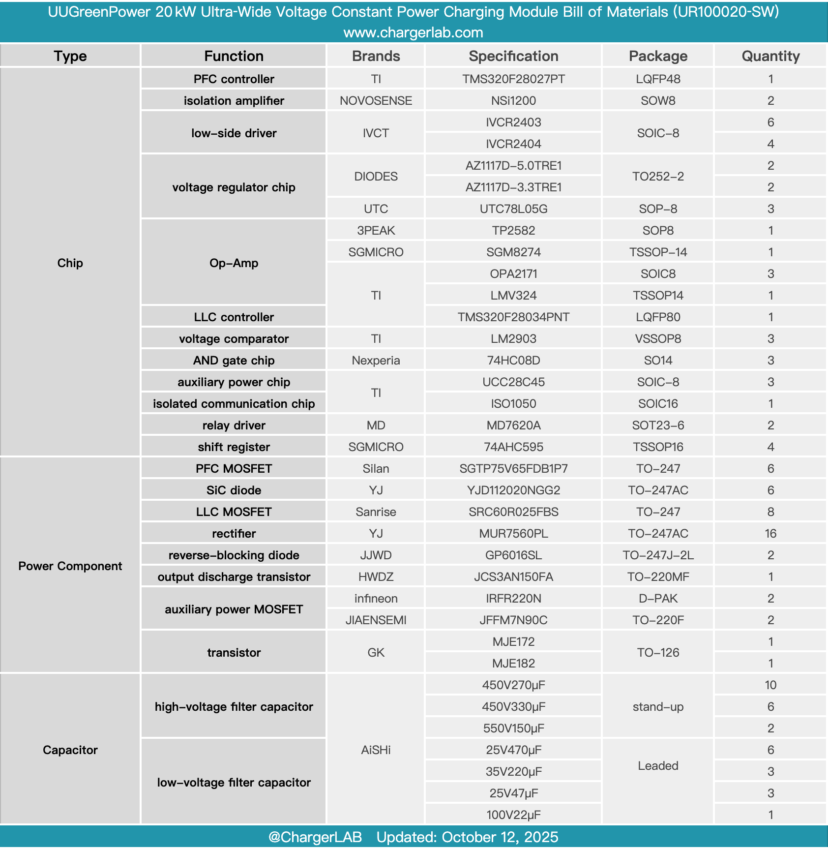
Here is the component list of the UUGreenPower UR100020‑SW 20 kW Ultra‑Wide Voltage Constant Power Charging Module for your convenience.
It supports a three-phase AC 380V input and an output voltage of up to 1000V, making it suitable for various voltage-level electric vehicle charging platforms. Two cooling fans are installed for thermal management. The rear is equipped with connection terminals for easy installation and maintenance. The system features multiple protection functions, including input and output overvoltage/undervoltage, overcurrent, and short-circuit protection. It uses DSP control, has an LED numeric display for information, and includes a CAN communication interface.
After taking it apart, we found that it contains two PCBA modules, corresponding to the PFC and LLC sections, connected via small PCBs and wiring. The PFC controller uses the Texas Instruments TMS320F28027PT and performs current sampling through NOVOSENSE NSi1200 isolation amplifiers. It is driven by six IVCT IVCR2403 devices. The PFC MOSFETs are Silan SGTP75V65FDB1P7, paired with YJ YJD112020NGG2 SiC diodes for rectification.
The LLC controller uses the Texas Instruments TMS320F28034PNT, with MOSFETs from Sanrise, model SRC60R025FBS, paired with YJ MUR7560PL rectifiers. Electrolytic capacitors are sourced from AiSHi, while film capacitors come from Faratronic. The PCBA modules are encapsulated, and the back side is coated with conformal coating, effectively enhancing product reliability and ensuring a better user experience.
Related Articles:
1. Teardown of Dell 280W USB-C GaN AC Adapter (LA280PM240)
2. Teardown of Bel Fuse 3000W GaN Server Power Supply (TET3000-12-069RA)
3. Teardown of Gospower 1300W DC Server Power Supply (G1232-1300WND)