Introduction
UGREEN recently launched two new retractable fast chargers with 45W and 65W power outputs. Both models come with a 70cm long USB-C retractable cable that starts charging as soon as it’s pulled out and automatically retracts when pulled again. This design offers convenience while keeping your desk neat and organized.
Through teardown analysis, it was found that the complete power solution for both chargers—including the integrated GaN chip, synchronous rectifier controller, and protocol chip—is provided by iSmartWare. Thanks to the use of the integrated GaN chip, the reference design circuit is very simple, which reduces design and manufacturing costs and enhances cost-effectiveness.
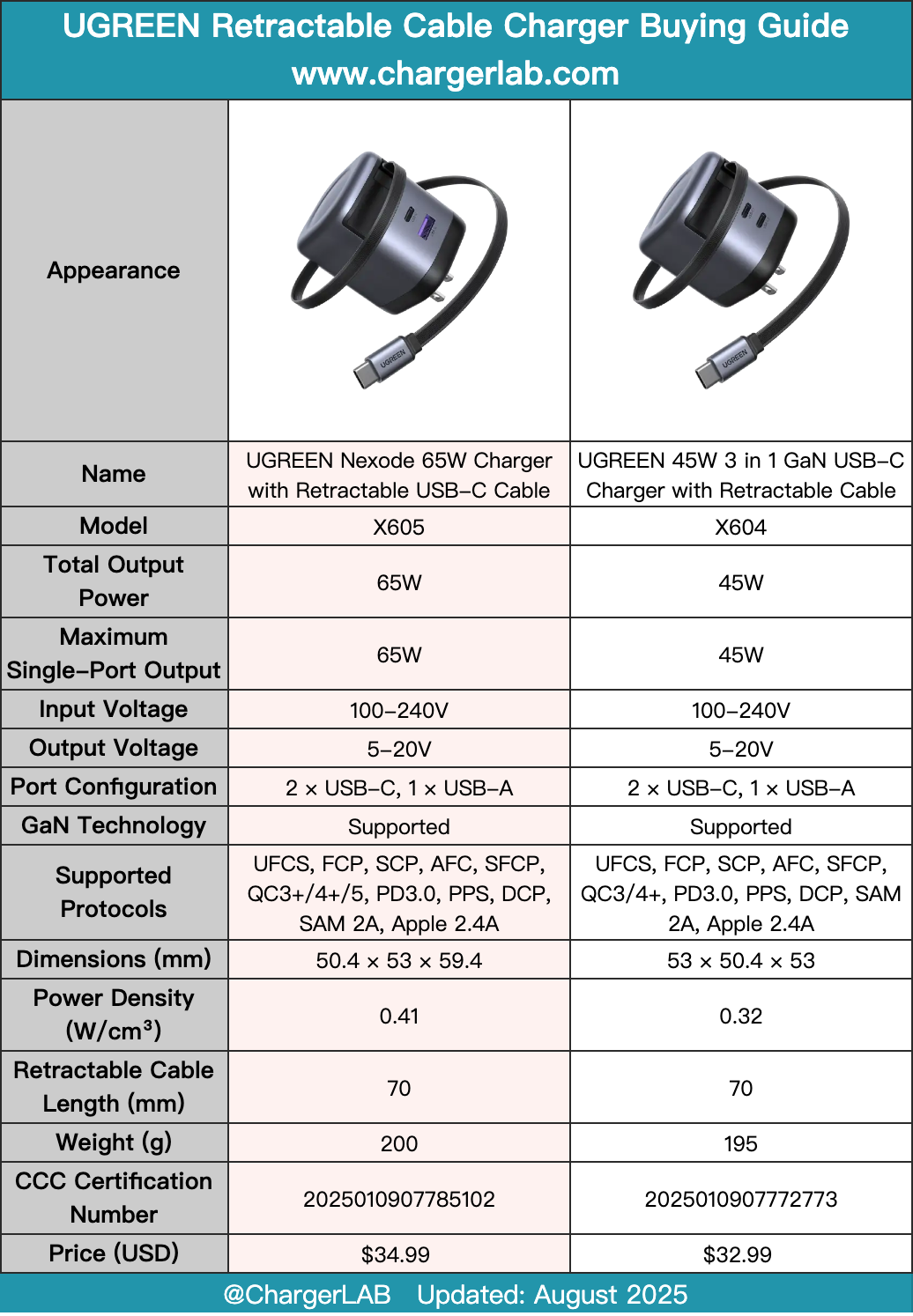
The retractable cable uses the patented GlideTurbo high-precision swivel shaft, supporting over 25,000 pulls for exceptional durability. It features 8 adjustable length settings for flexible use. The charger is designed based on an advanced GaN power solution, with a compact body and foldable plug.
The USB-C port and retractable cable support 65W and 60W PD fast charging, respectively, while the USB-A port supports 22.5W fast charging. It can fast charge multiple devices such as phones, tablets, laptops, and headphones. Now, let's take a closer look at the charger’s specific design.
Product Appearance
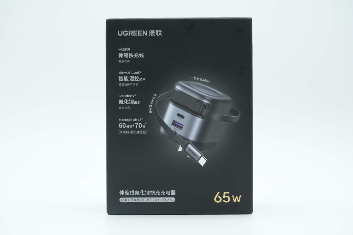
The front of the packaging features the UGREEN logo, the product name, a visual of the product, and key selling points.
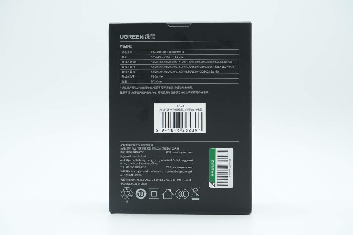
The back displays the product specifications, safety information, and other notices.
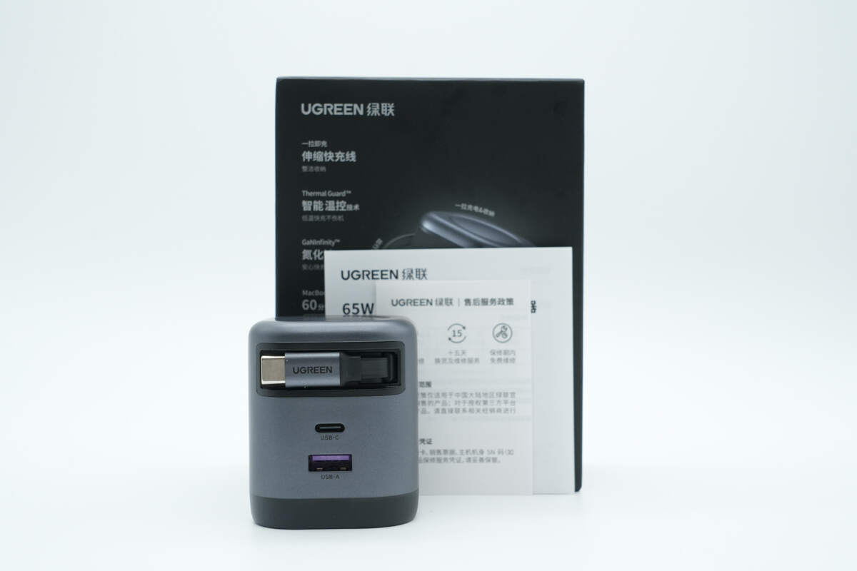
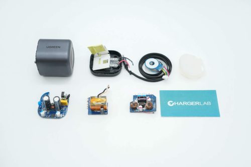
The package includes the charger and some documents.
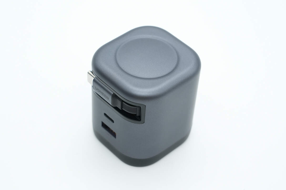
The top features a circular recessed area with smoothly rounded edges.
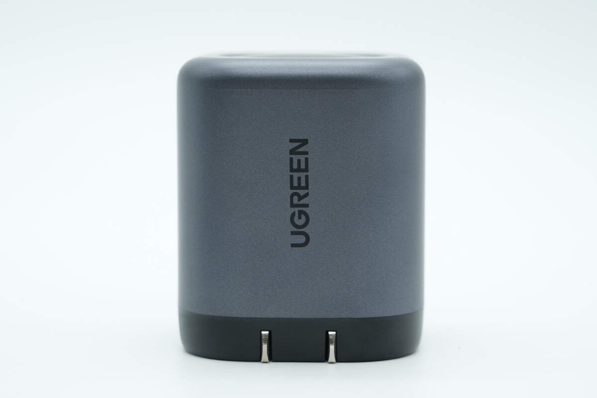
This side is printed with the UGREEN logo.
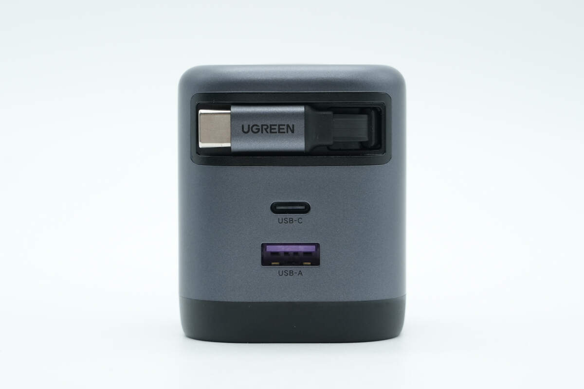
This side has the retractable USB-C cable, along with one USB-C port and one USB-A port.
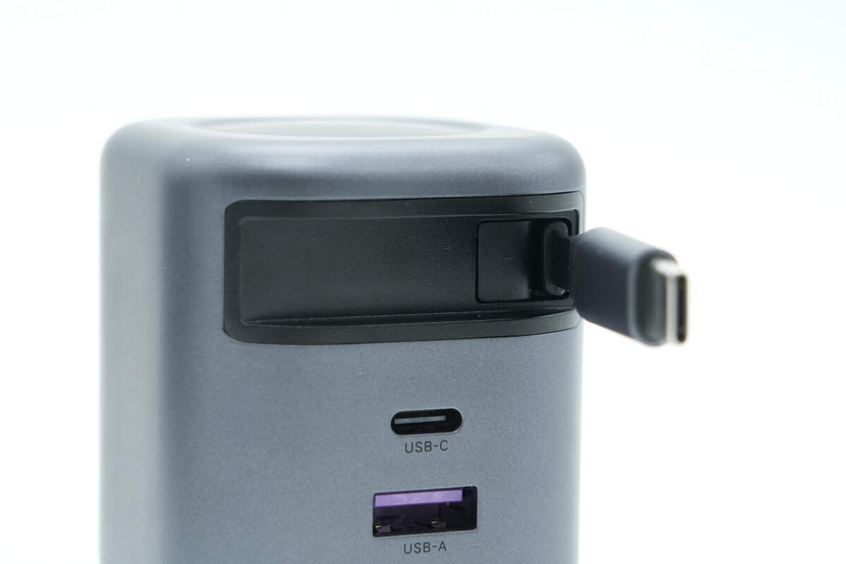
Inside the cable groove, there is a magnet used to secure the connector.
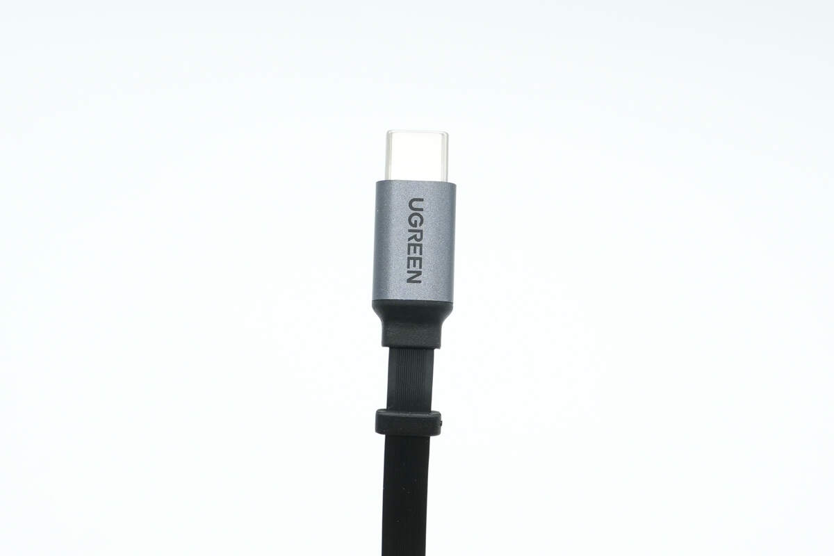
The connector has a metal casing and is marked with the UGREEN logo.
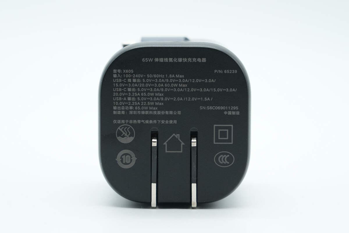
The input side is printed with the specification information.
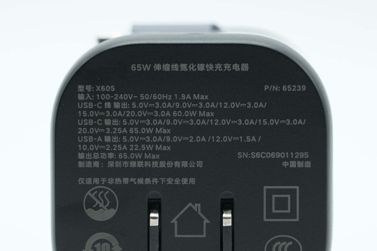
Model: X605
Input: 100-240V\~50/60Hz 1.8A Max
USB-C Cable Output: 5V 3A, 9V 3A, 12V 3A, 15V 3A, 20V 3A, 60W Max
USB-C Output: 5V 3A, 9V 3A, 12V 3A, 15V 3A, 20V 3.25A, 65W Max
USB-A Output: 5V 3A, 9V 2A, 12V 1.5A, 10V 2.25A, 22.5W Max
Total Output Power: 65W Max
Certified by CCC.
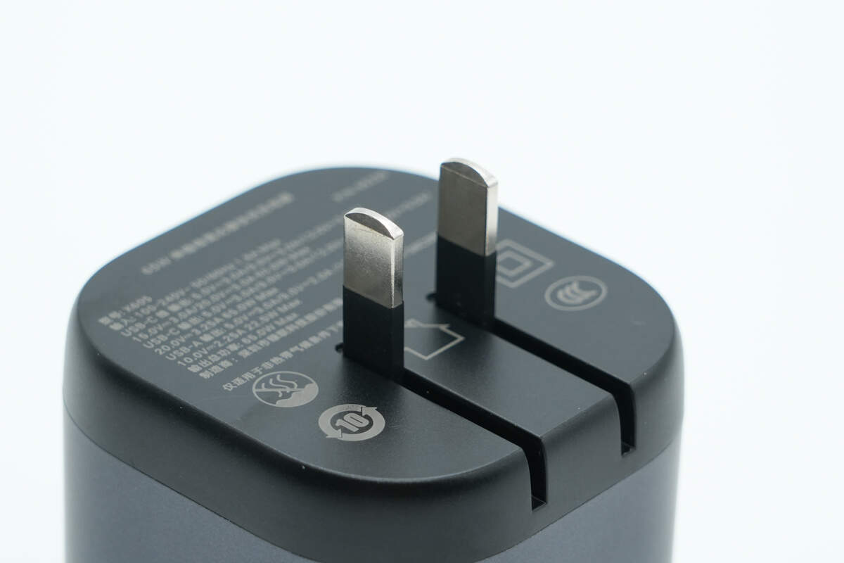
It is equipped with a foldable plug, making it portable.
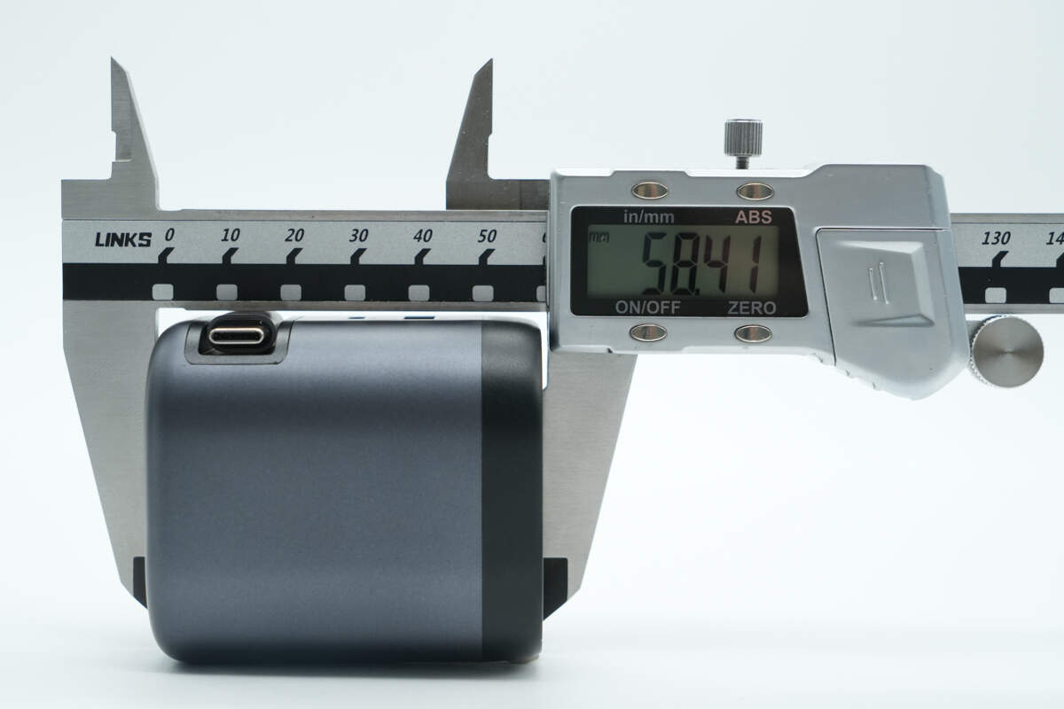
The height of the charger is about 58.41 mm (2.3 inches).
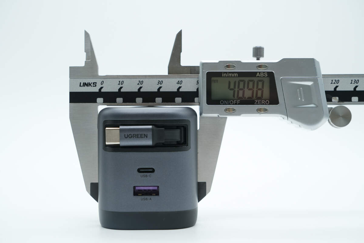
The width is about 48.98 mm (1.93 inches).
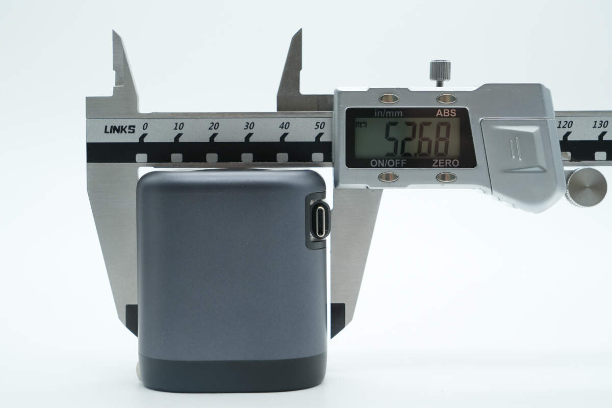
The thickness is about 52.68 mm (2.074 inches).
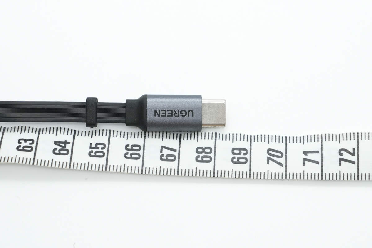
The length of the cable is about 68 cm (26.77 inches).
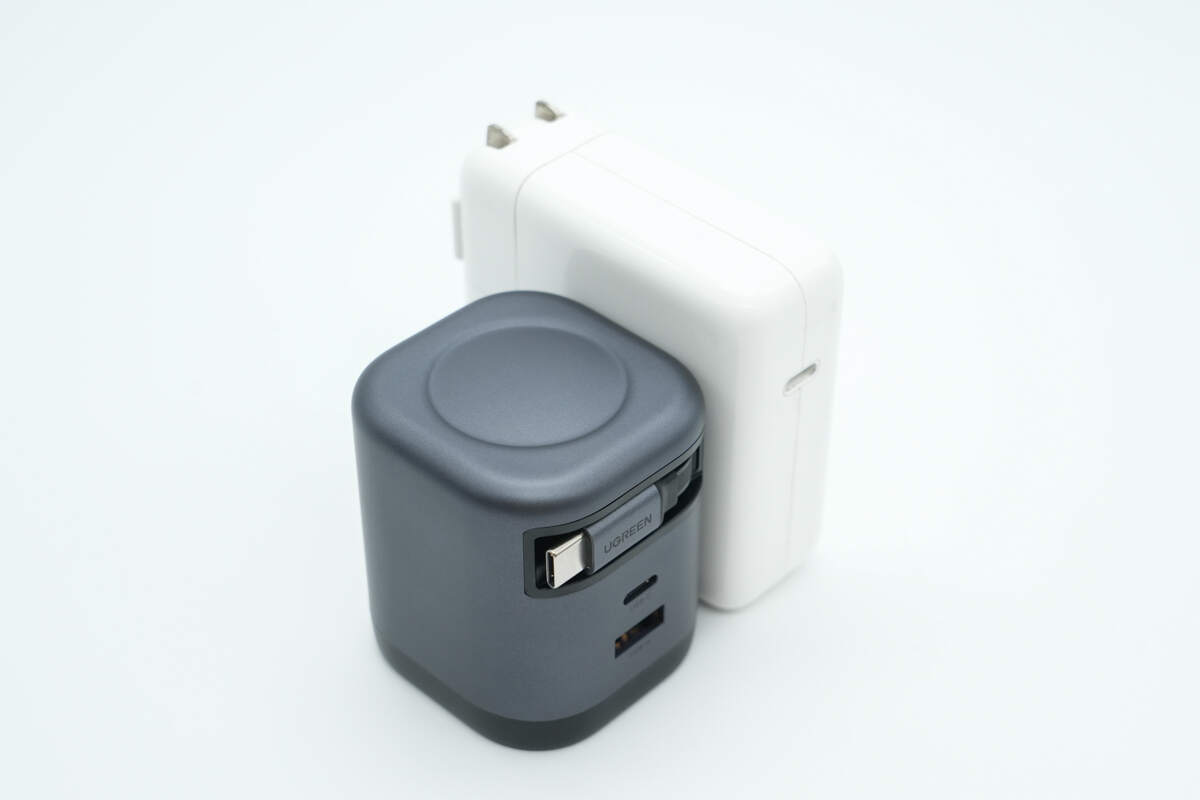
Compared side by side with the Apple 67W charger for comparison.
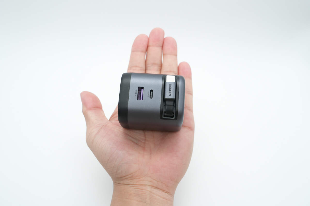
That's how big it is in the hand.
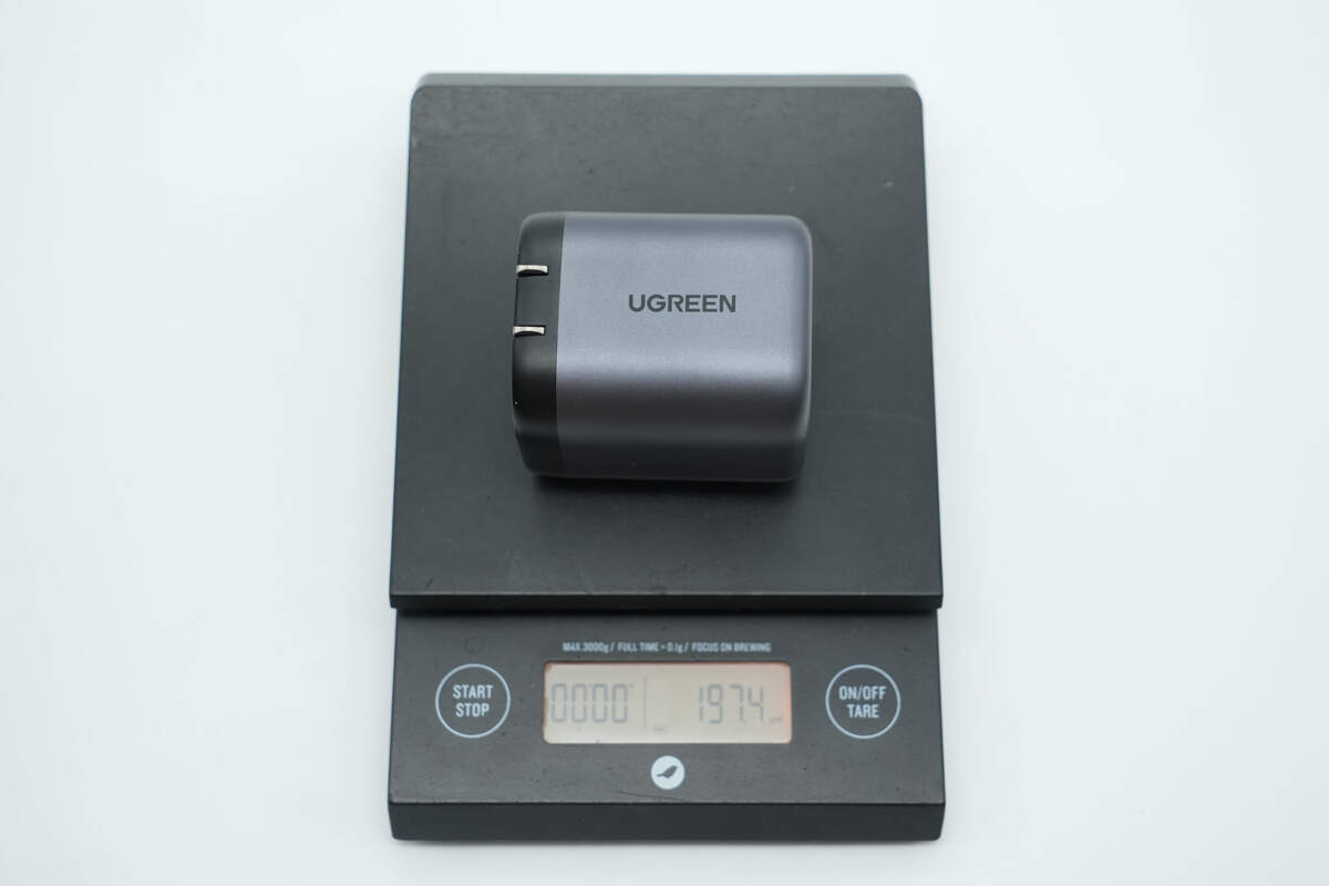
The weight is about 197 g (6.95 oz).
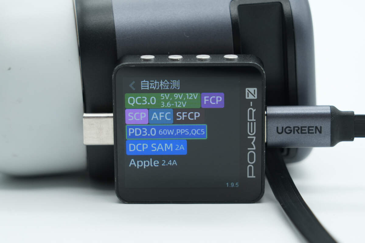
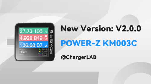
ChargerLAB POWER-Z KM003C shows that the USB-C cable supports FCP, SCP, AFC, SFCP, QC3.0/5, PD3.0, PPS, DCP, SAM 2A, and Apple 2.4A charging protocols.
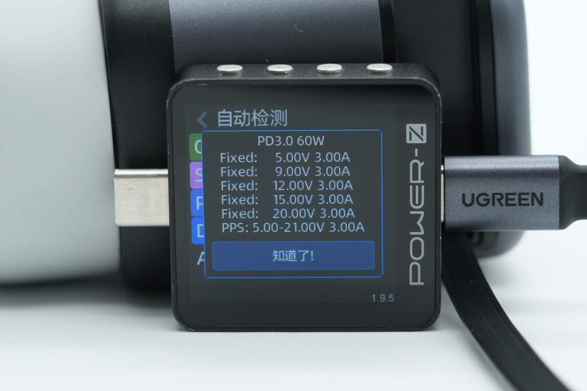
And it has five fixed PDOs of 5V3A, 9V3A, 12V3A, 15V3A, and 20V3A. It has one set of PPS, which is 5-21V3A.
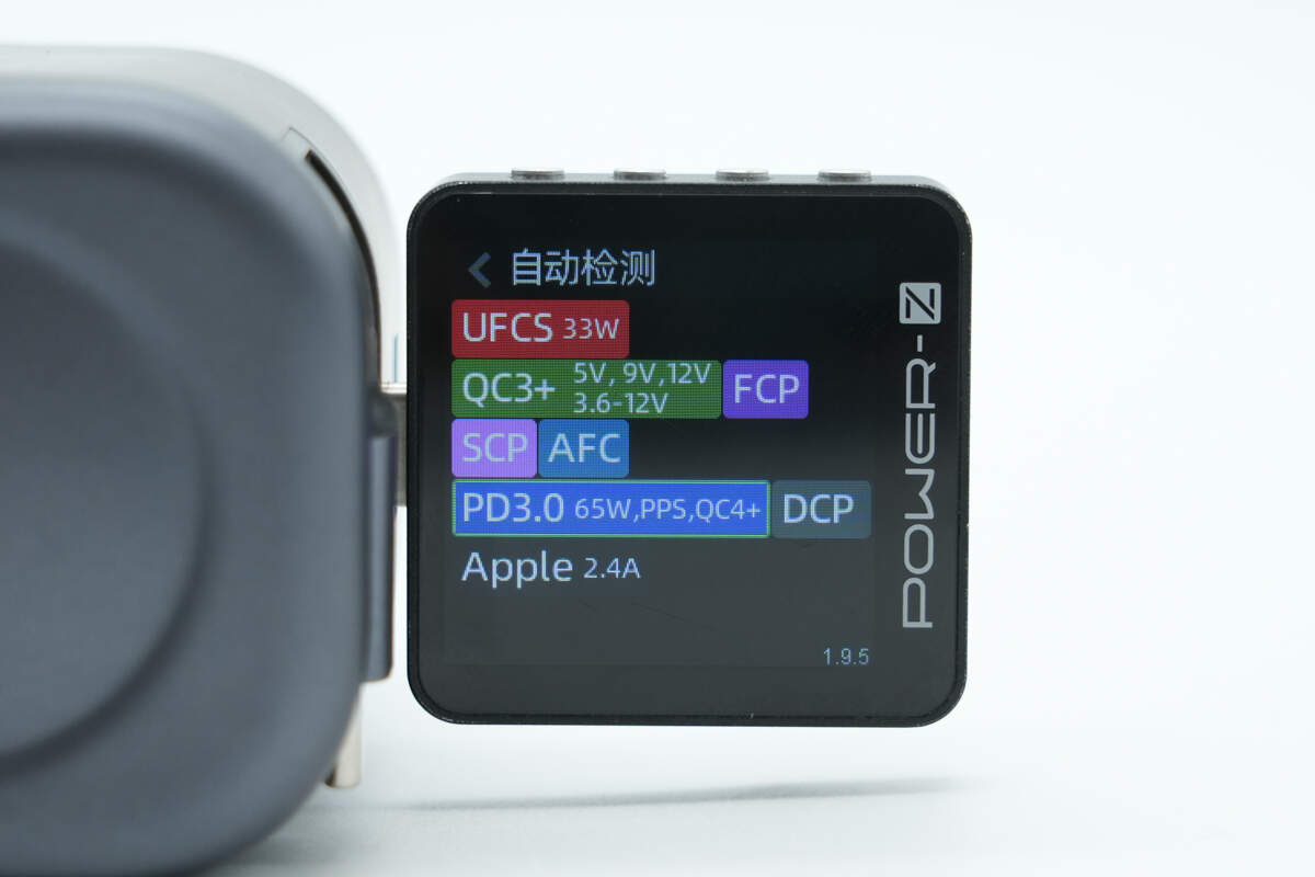
ChargerLAB POWER-Z KM003C shows that the USB-C port supports UFCS, FCP, SCP, AFC, QC3+/4+, PD3.0, PPS, DCP, and Apple 2.4A charging protocols.
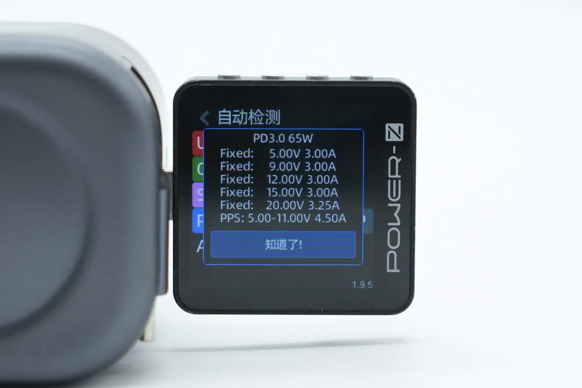
And it has five fixed PDOs of 5V3A, 9V3A, 12V3A, 15V3A, and 20V3.25A. It has one set of PPS, which is 5-11V4.5A.
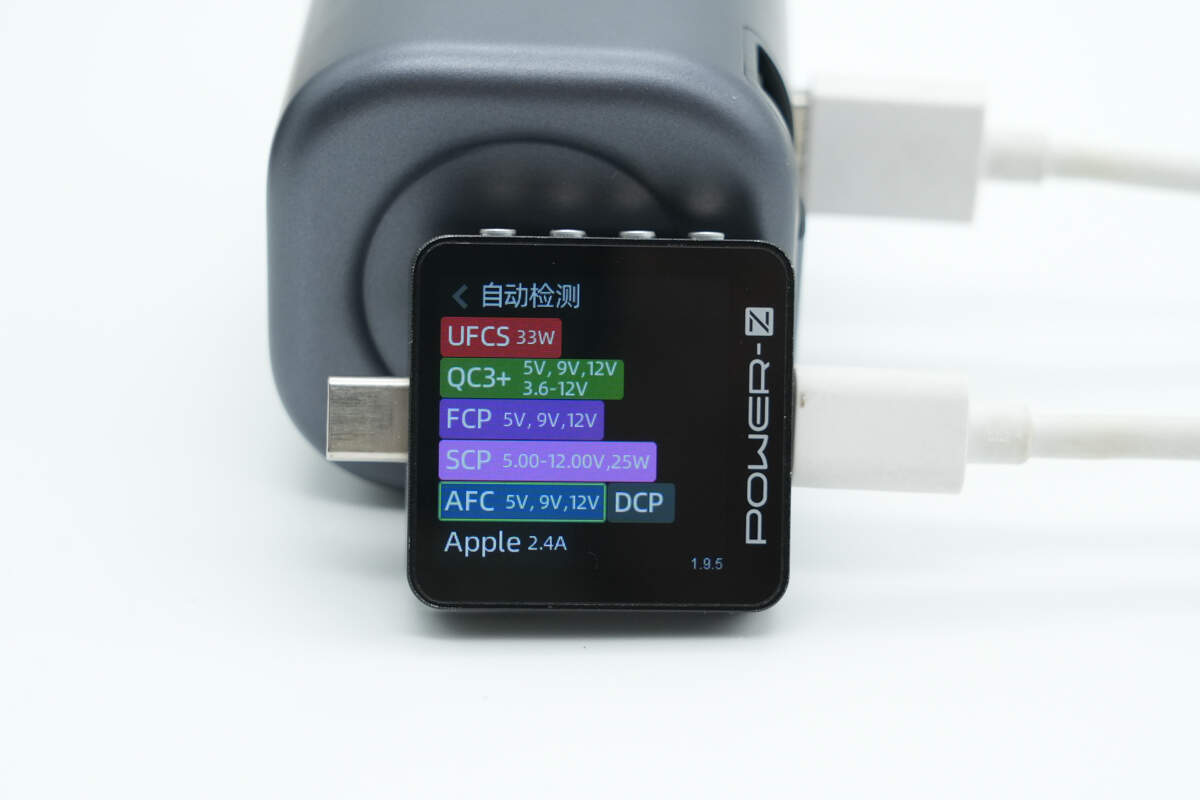
The USB-A port supports UFCS, QC3+, FCP, SCP, AFC, DCP, and Apple 2.4A charging protocols.
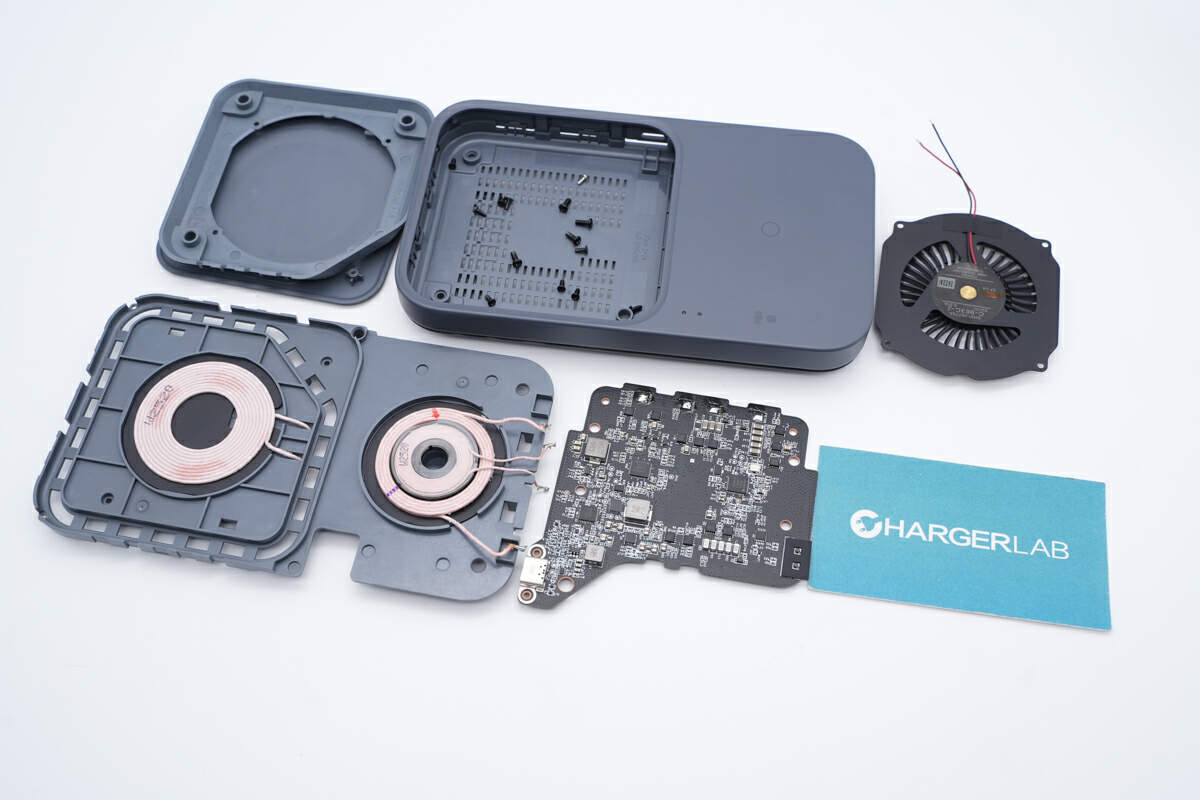
Teardown
Next, let's take it apart to see its internal components and structure.
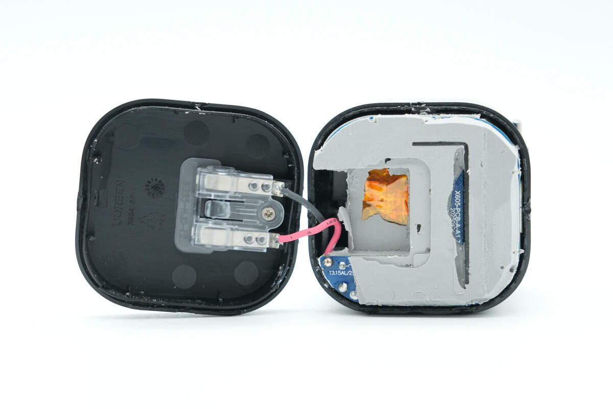
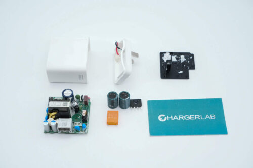
Remove the bottom casing. The plug is connected to the PCBA module through wires.
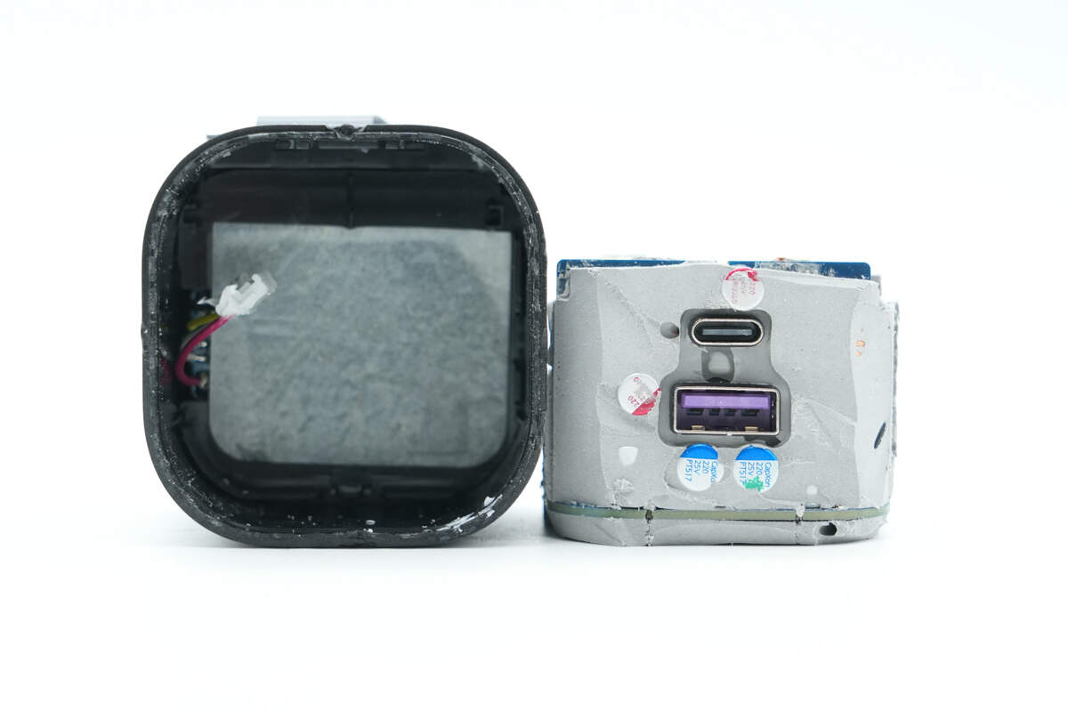
Remove the PCBA module. The module is encapsulated with thermal adhesive.
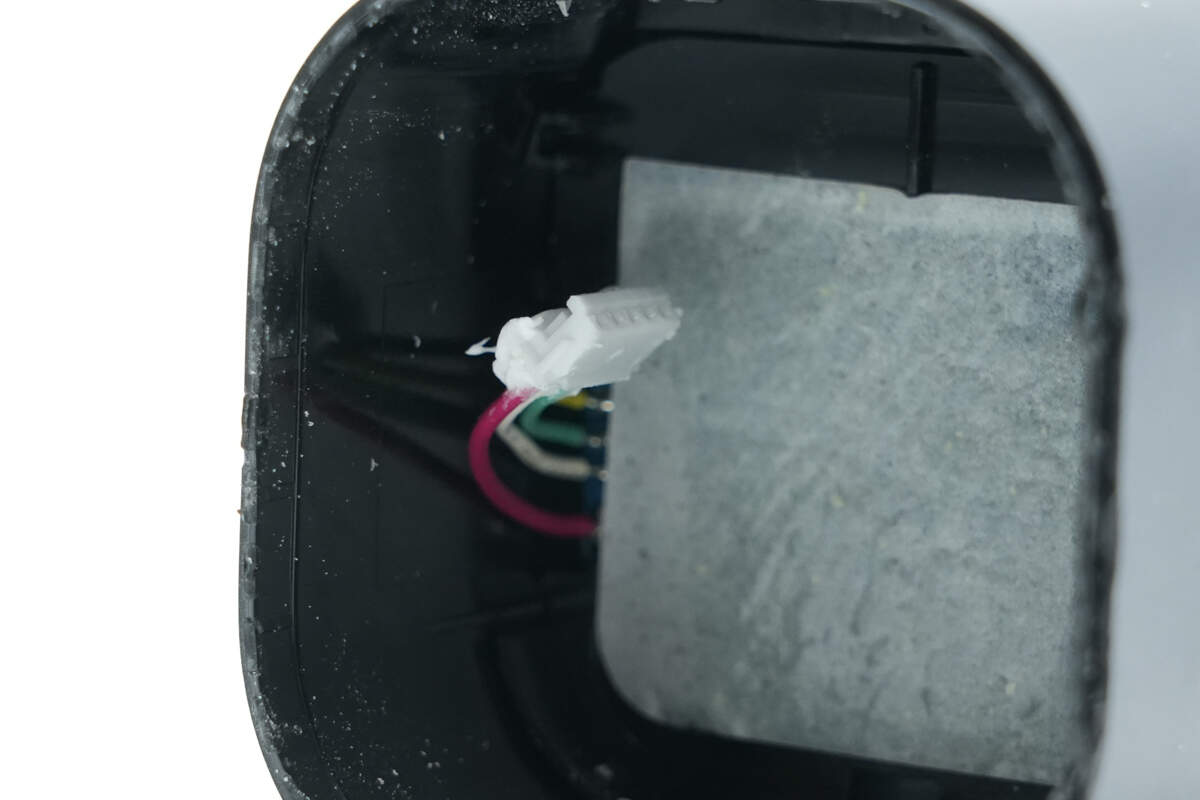
The retractable cable and the PCBA module are connected via a plug-and-play interface, allowing easy disassembly.
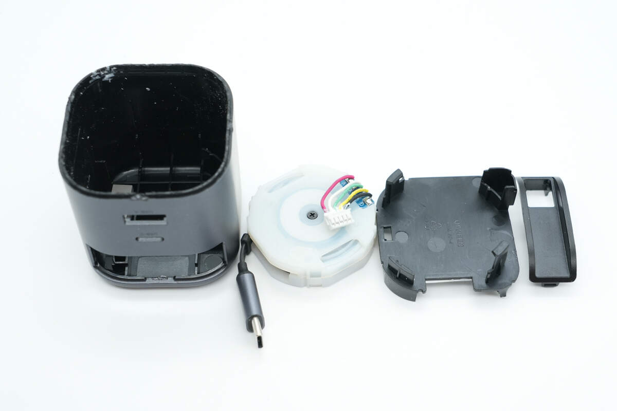
Remove the retractable cable module. The module has a white plastic casing and is separated from the PCBA module by a black plastic plate.
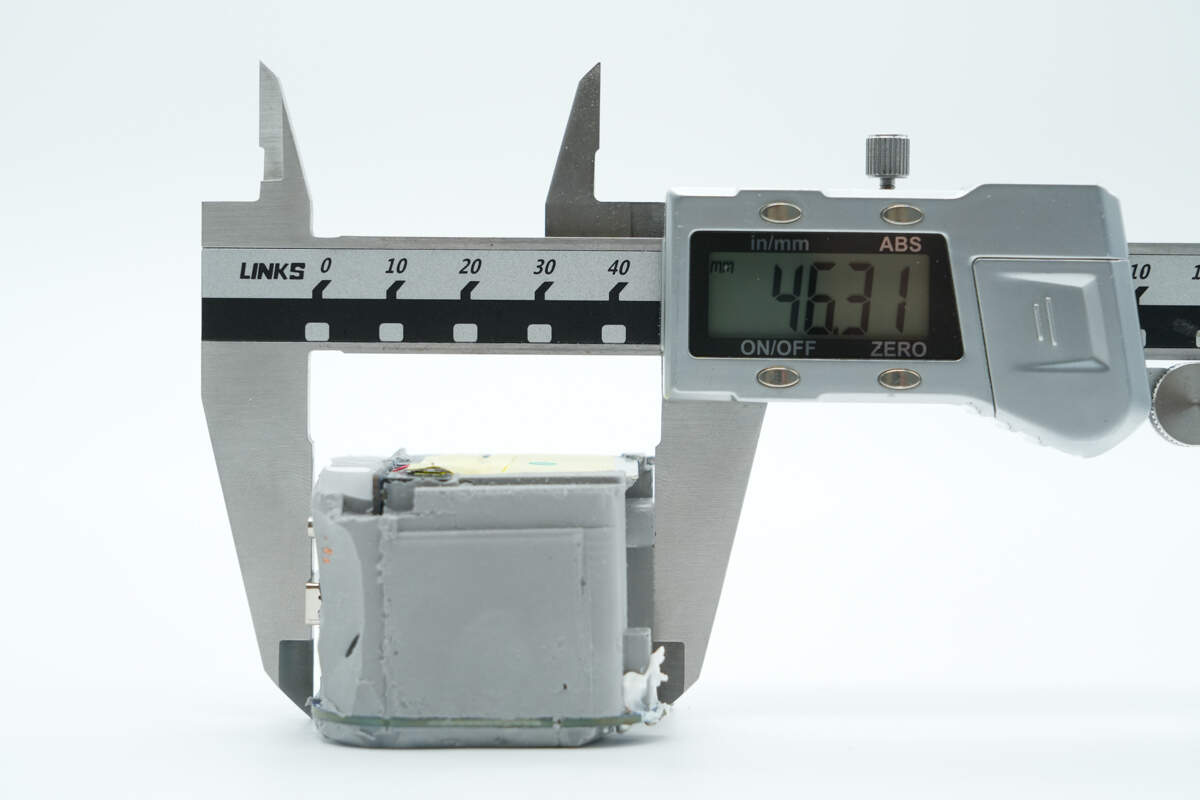
The length of the PCBA module is about 46.31 mm (1.82 inches).
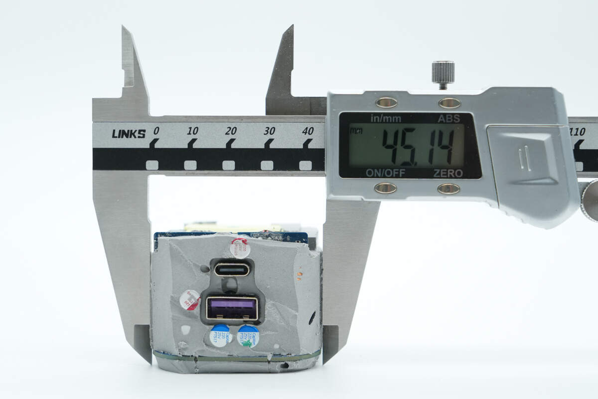
The width is about 45.14 mm (1.78 inches).
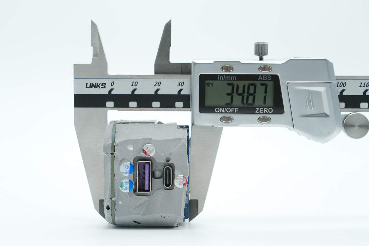
The thickness is about 34.87 mm (1.37 inches).
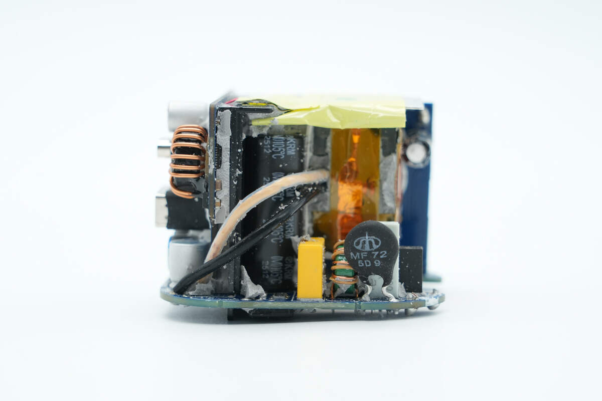
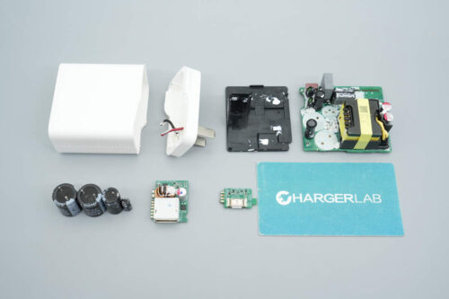
Clean off the thermal adhesive. The front side is equipped with a time-delay fuse, NTC thermistor, common mode choke, safety X2 capacitor, and electrolytic capacitors. There is a plastic isolation plate between the capacitors and the output PCB.
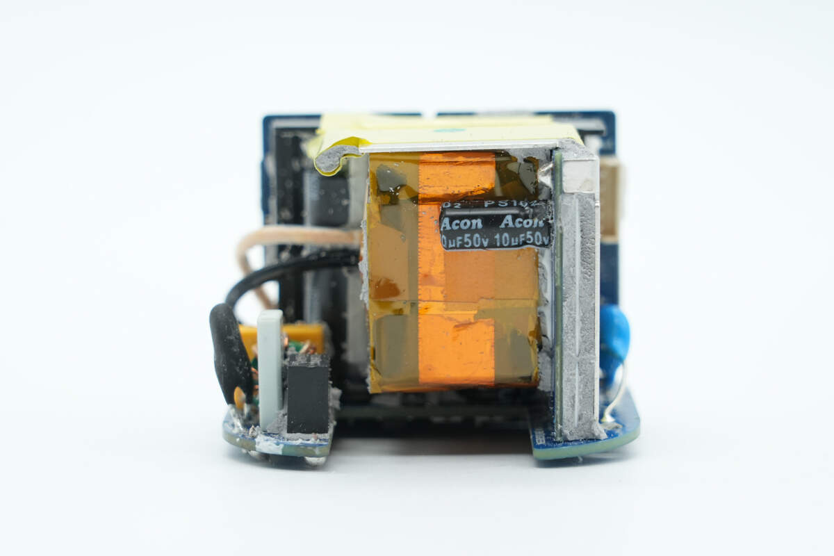
There is a small PCB on the right side of the module. One side of the PCB houses the transformer and a capacitor that powers the master control chip.
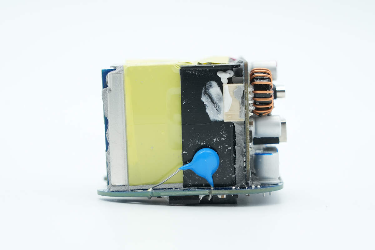
The other side and the top of the PCB are covered with an integrated heat sink, which is also wrapped with insulating tape. There is a blue varistor on the main PCB.
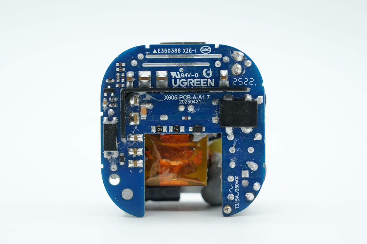
On the back of the main PCB, there is a bridge rectifier and an optocoupler.
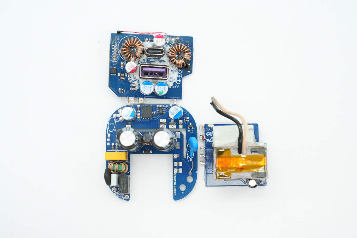
Disassemble the PCBA module to facilitate inspection of the components.
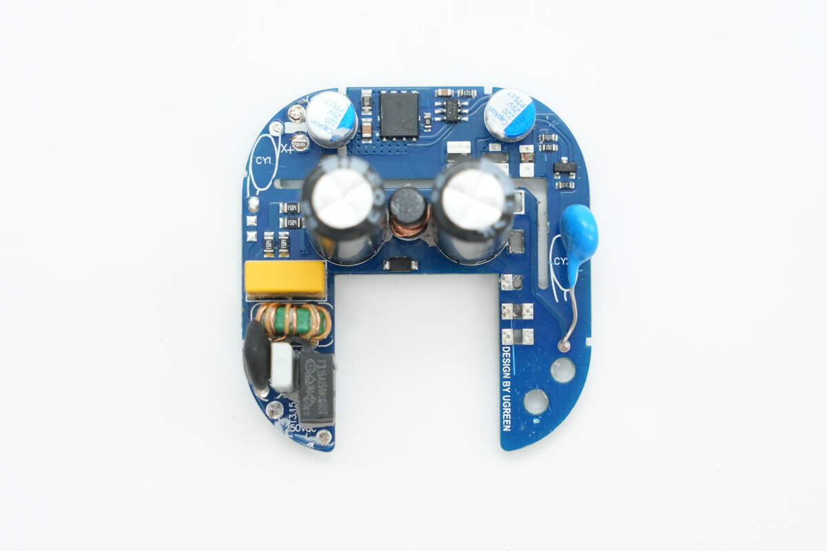
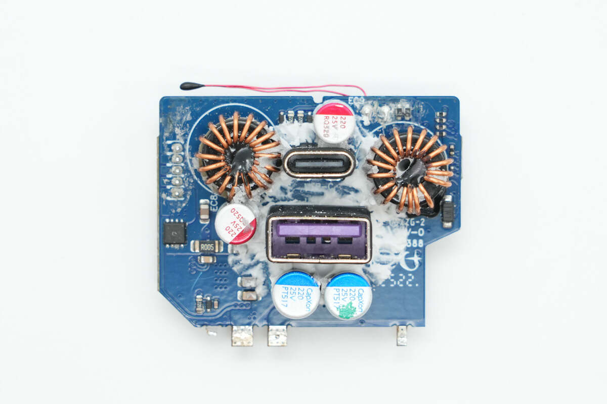
The front side of the main PCB features electrolytic capacitors, an I-shaped inductor, a synchronous rectifier controller, a synchronous rectifier, and solid capacitors.
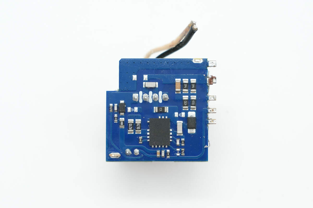
The other side of the small PCB is equipped with the master control chip.
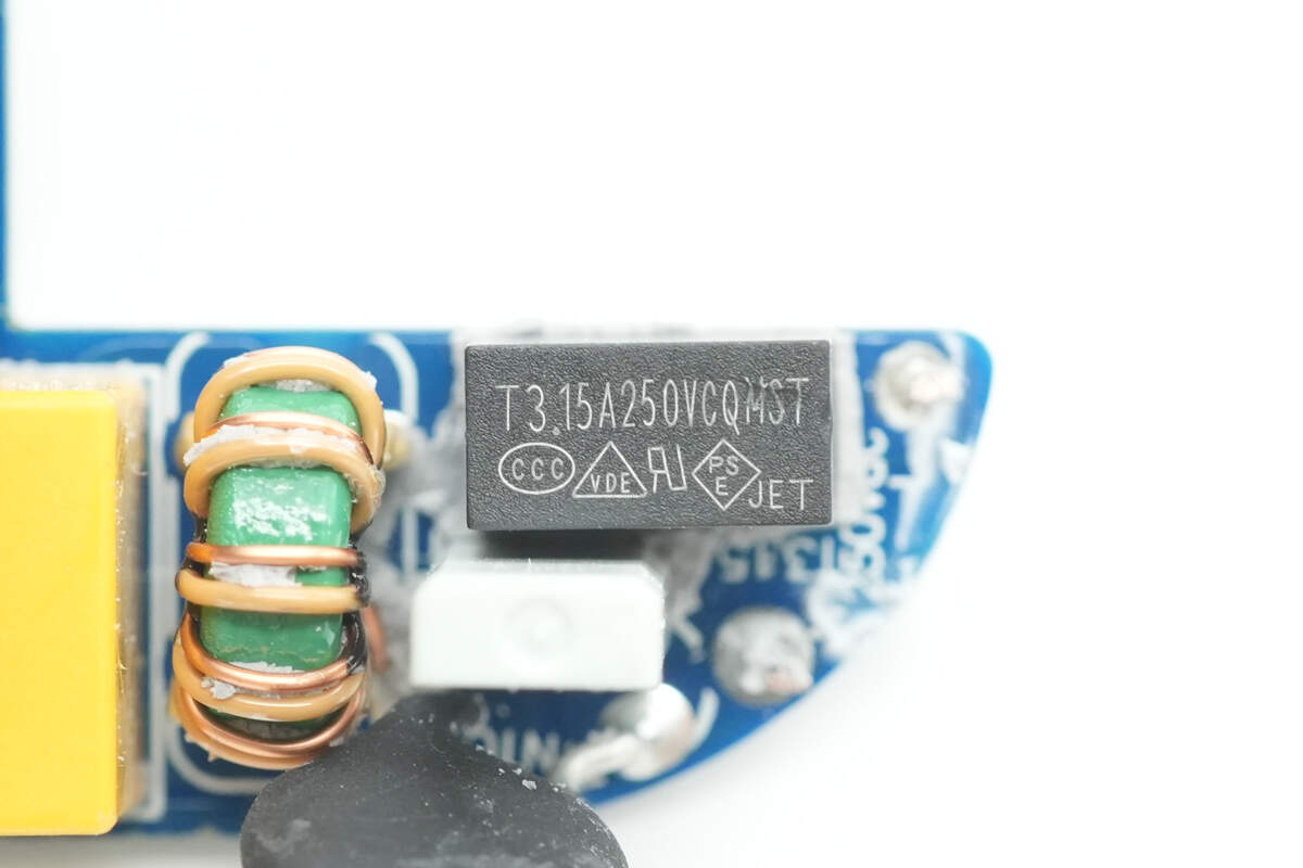
The time-delay fuse is rated at 3.15A, 250V.
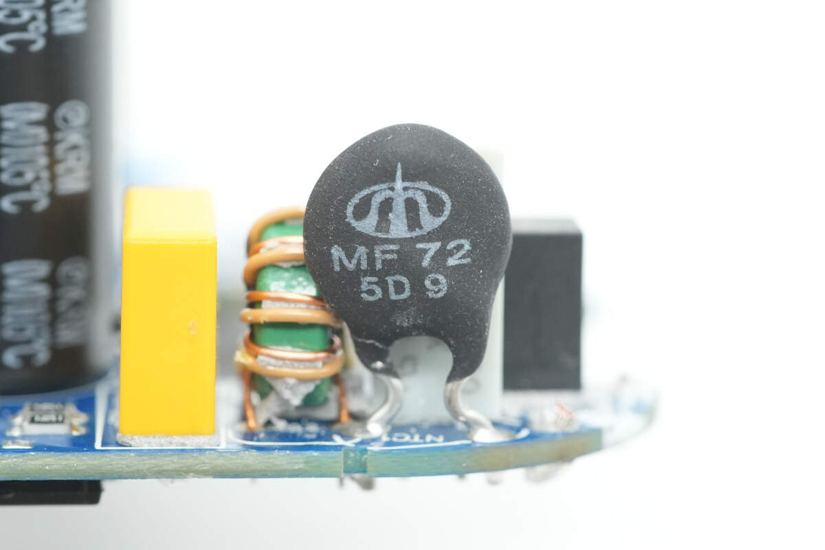
The NTC thermistor is from Shiheng, part of the MF72 series, and is used to suppress inrush current during power-up.
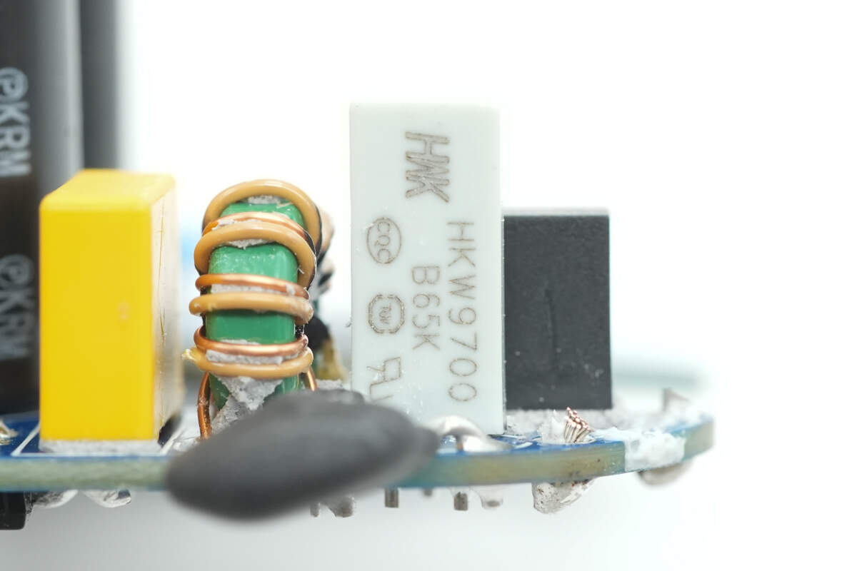
The thermal protector is from HKW, model HKW9700.
The HKW9700 temperature switch is cleverly applied in this design. When the power supply is in a cold start state, the NTC thermistor effectively suppresses the inrush current. Once the power supply enters normal operation, the temperature switch detects the heat generated by the NTC thermistor and closes the circuit to short it, thereby eliminating the series loss of the thermistor.
This design is quite ingenious, as it fully leverages the complementary characteristics of the components. It not only suppresses inrush current during cold start, but also improves power conversion efficiency and reduces temperature rise within the power supply.
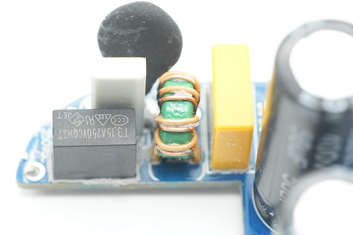
The common mode choke is wound with two wires and is used to filter out EMI interference.
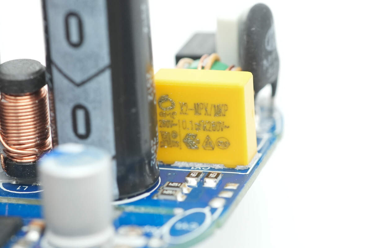
The safety X2 capacitor is from EMF with a capacitance of 0.1μF.
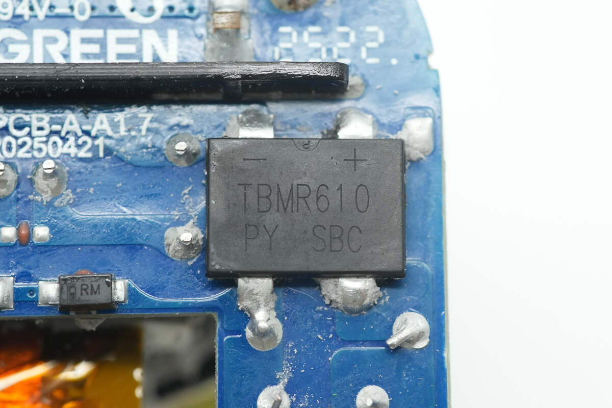
The bridge rectifier is from PY, model TBMR610, rated at 6A 1000V, and uses a TBM package.
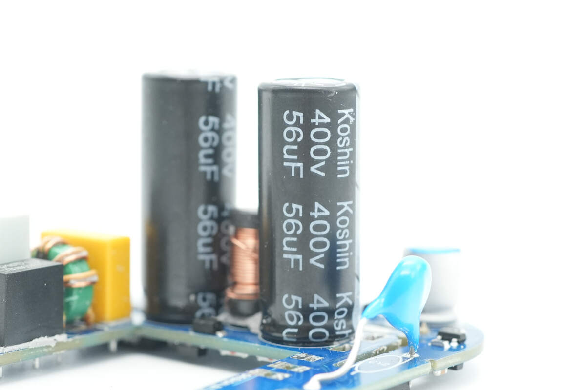
The two electrolytic capacitors are from Koshin, both rated at 400V 56μF.
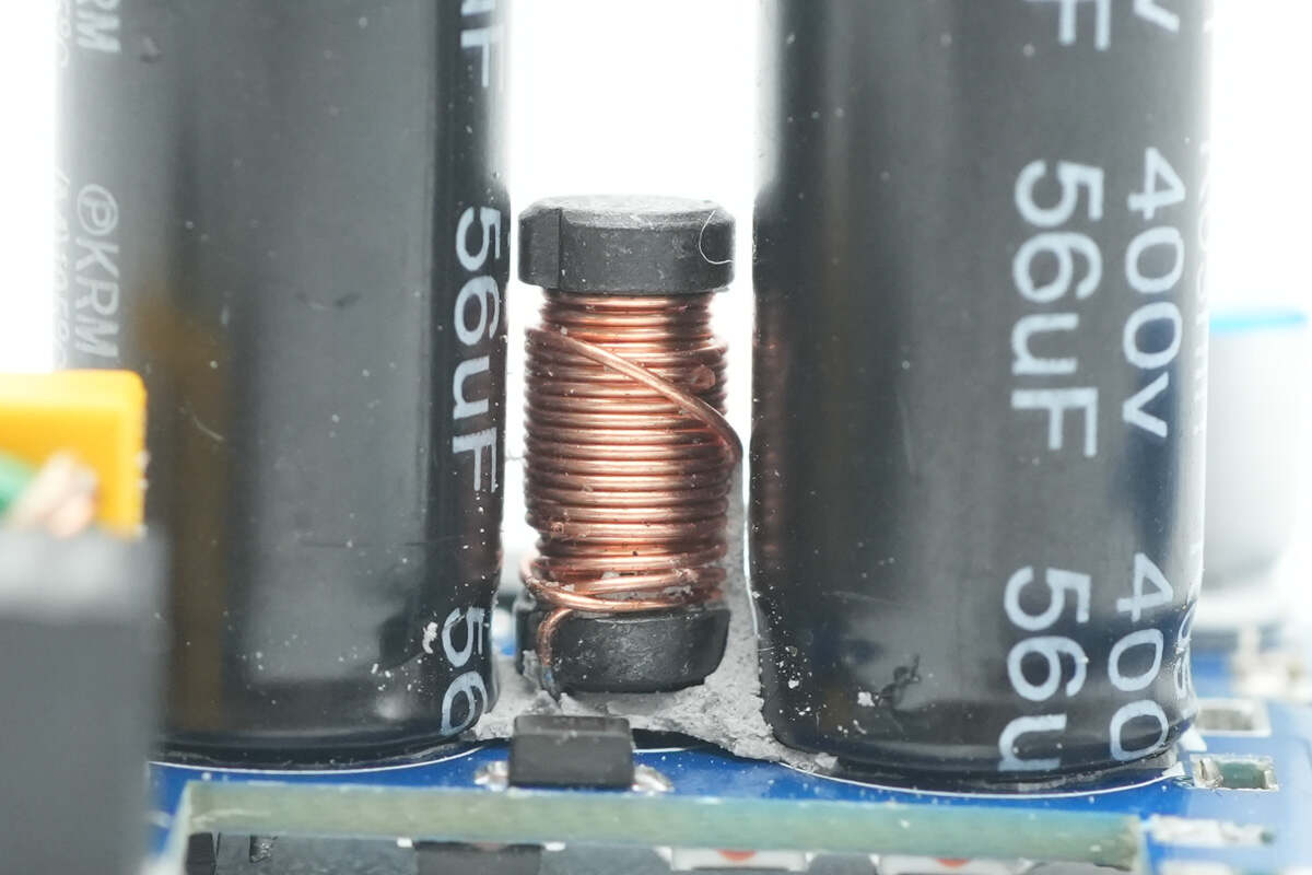
Close-up of the I-shaped inductor.
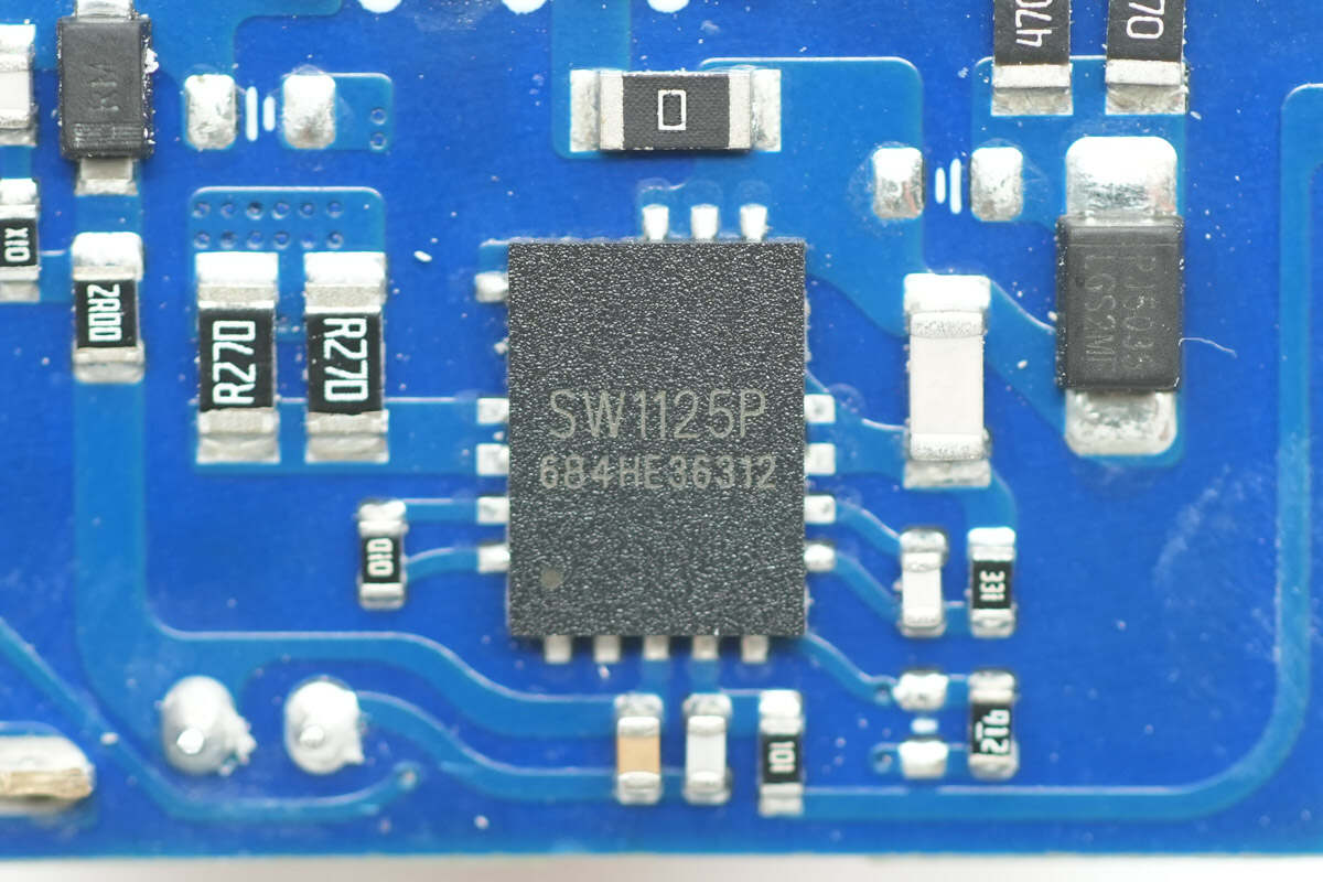
The master control chip used is the iSmartWare SW1125P. It is a high-frequency quasi-resonant flyback converter integrating a 700V-rated GaN FET with an on-resistance of 260mΩ. The chip includes a built-in 700V high-voltage startup circuit, line voltage dropout detection, and X-capacitor discharge function.
It operates in valley-switching mode with valley-locking to reduce switching losses and features frequency jittering to optimize EMI performance. The chip supports burst mode, automatically entering burst mode at light loads to improve efficiency. Its no-load standby power consumption is below 50mW, meeting Level 6 energy efficiency standards.
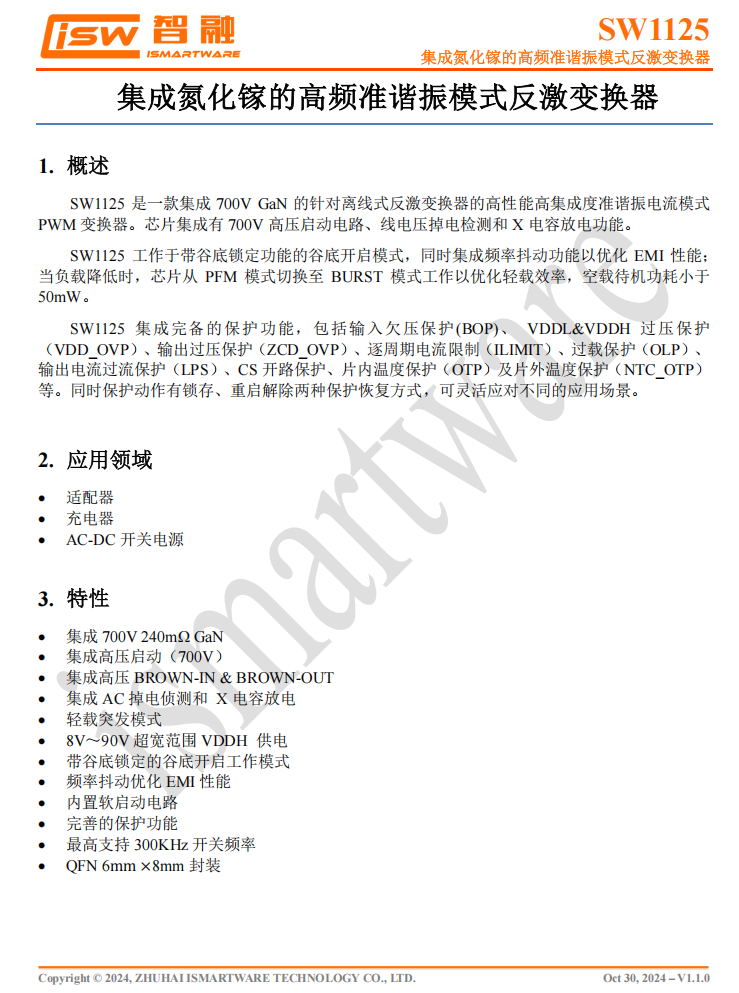
The SW1125P supports an ultra-wide input voltage range of 8–90V and a maximum switching frequency of up to 300kHz. It comes in a thermally enhanced QFN 6×8 package, allowing heat dissipation through vias to reduce chip temperature, optimize PCB layout, and simplify thermal management.
It features multiple comprehensive built-in protection functions and supports external NTC thermistor input for charger temperature monitoring, enabling a thorough protection design.
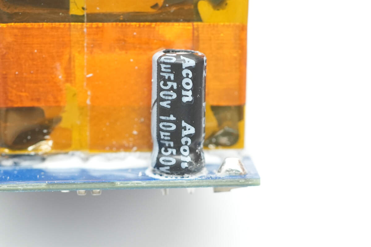
The capacitor that powers the master control chip is from Acon, rated at 50V 10μF.
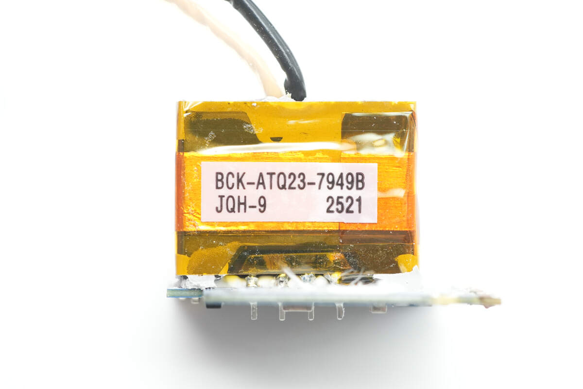
The transformer is wrapped with high-temperature insulating tape and uses an ATQ23 magnetic core.
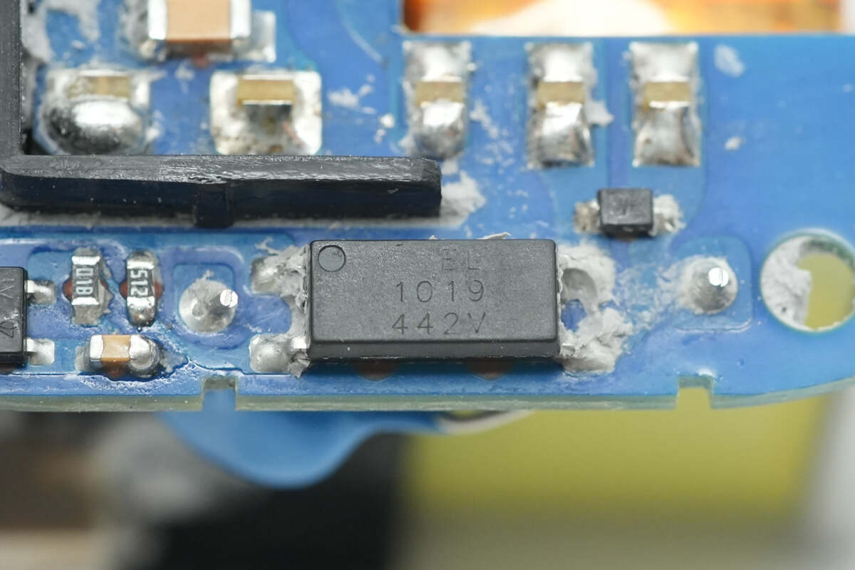
The Everlight EL1019 optocoupler is used for output voltage feedback.
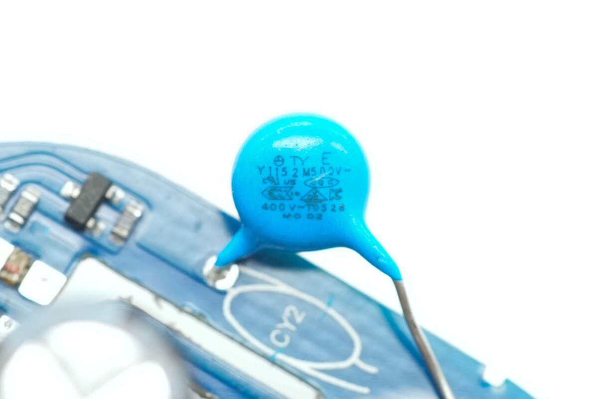
Close-up of the blue Y capacitor.
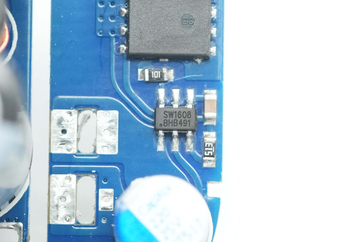
The synchronous rectifier controller uses the iSmartWare SW1608, a high-performance controller designed for the secondary-side synchronous rectifier (MOSFET) drive in offline flyback converters. It comes in an SOT23-6 package and supports 6V or 9V VCC power supply. The VCC features self-powering capability, eliminating the need for an auxiliary winding power supply and supports a wide output voltage range. Used in conjunction with MOSFETs to replace Schottky rectifier diodes, it can significantly improve system efficiency.
The SW1608 supports an operating frequency of up to 600kHz and is compatible with both High Side and Low Side applications. It supports multiple working modes, including CCM, QR), and DCM.
Additionally, it features an integrated smart conduction detection function that effectively prevents false conduction caused by DCM ringing. It also offers ultra-low turn-off propagation delay and strong pull-down current capability, which significantly reduces the voltage stress on the rectifier MOSFET.
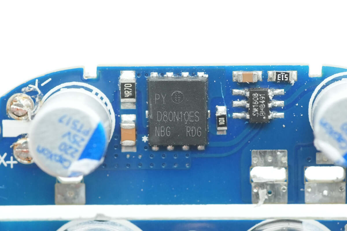
The synchronous rectifier is from PY, marked D80N10ES. It is an NMOS with a voltage rating of 100V, housed in a DFN 5×6 package.
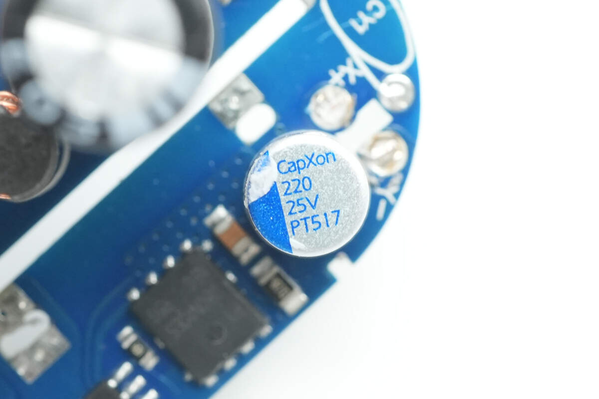
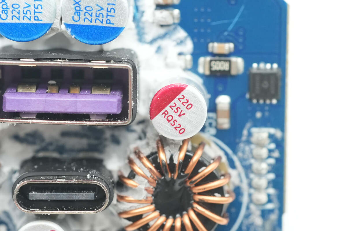
The solid capacitor is from CapXon, rated at 25V 220μF.
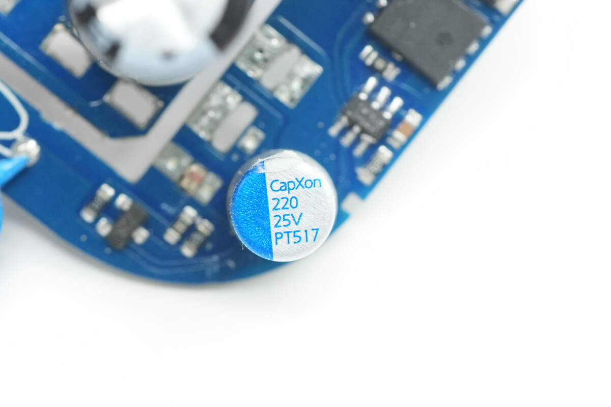
The other one is also from CapXon with the same specifications.
The front side of the output PCB is equipped with solid capacitors, buck inductors corresponding to two secondary buck circuits, and output VBUS MOSFETs.
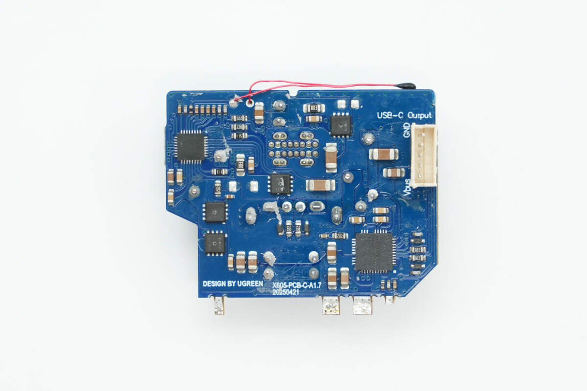
The back side has buck converter chips, synchronous buck MOSFETs, VBUS MOSFETs, and a thermistor.
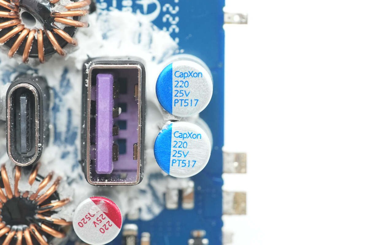
The other two solid capacitors are also from CapXon, rated at 25V 220μF.
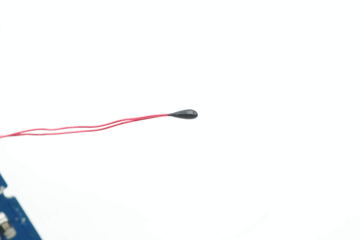
Close-up of the thermistor.
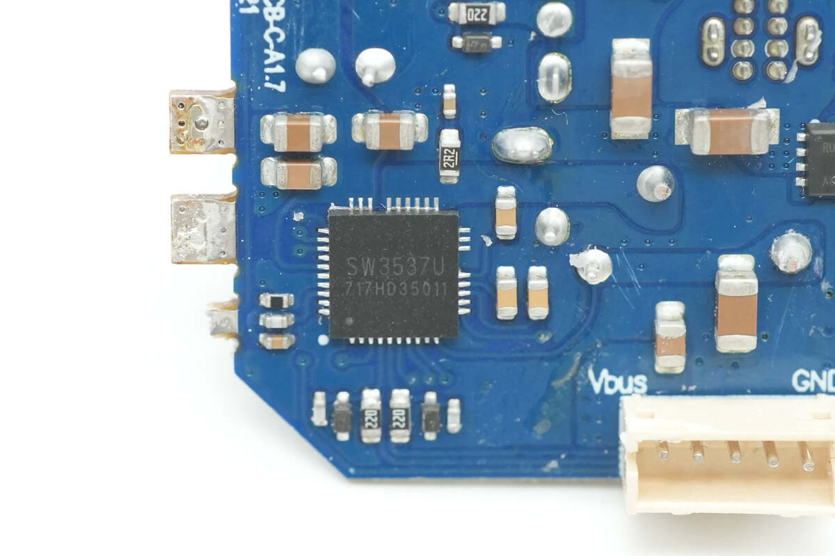
The USB-C cable’s buck protocol chip is the iSmartWare SW3537U. It integrates a 5A high-efficiency synchronous rectification buck converter and supports multiple charging protocols, including PPS, PD, QC, AFC, FCP, SCP, PE, SFCP, and low-voltage direct charging. It operates in CC/CV mode and requires only a few external components to form a complete high-performance multi-fast-charge dual-port charging solution. It is widely used in car chargers, adapters, and power strips.
Thanks to its high integration, the SW3537U combines the traditional protocol chip, synchronous buck controller, and buck MOSFETs into a single package, greatly simplifying the circuit design for multi-port fast charging. It supports dual-port fast charging for A+C ports, features comprehensive protection functions, and comes in a QFN-37 package.
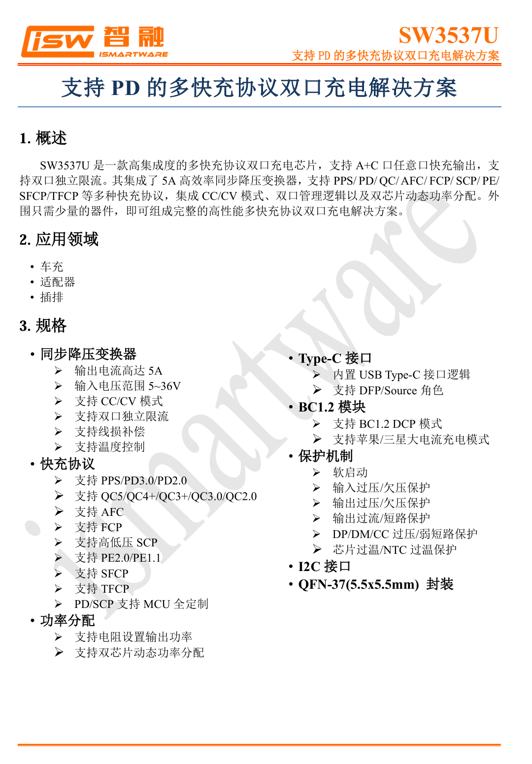
Here is the information about iSmartWare SW3537U.
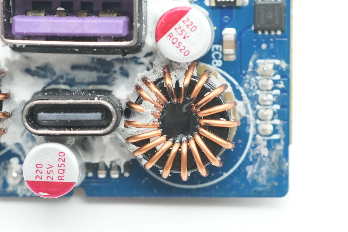
The paired buck inductor is reinforced with adhesive applied at the center and has a bakelite sheet padding at the bottom.
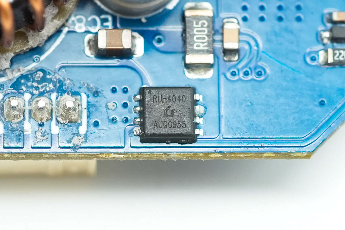
The output VBUS MOSFET is from Ruichips, model RUH4040. It is an NMOS with a voltage rating of 40V and an on-resistance of 8mΩ, housed in a PDFN3333 package.
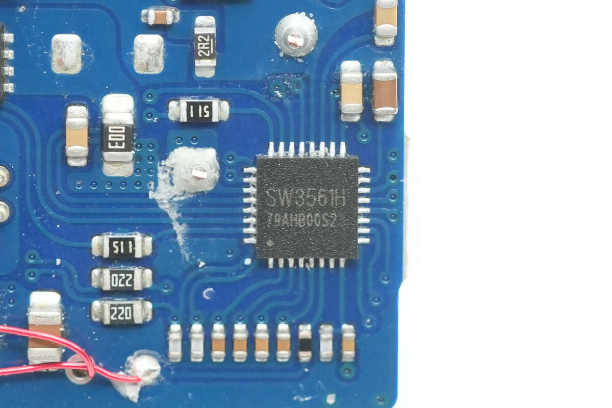
The buck protocol chips for the two ports use the iSmartWare SW3561H, a buck SoC that supports dual USB-C outputs. It integrates a high-efficiency synchronous buck controller, supports 20V/5A power output, and complies with USB PD 3.1 SPR. The chip features an internal ARM Cortex-M0 core and integrated Type-C logic, supporting PD 3.1, QC, SCP, UFCS fusion fast charging protocols, and customizable fast charging protocols.
It supports dual USB-C port path control and line loss compensation. Paired with two synchronous buck MOSFETs and corresponding VBUS MOSFETs, it enables dual-port buck output. The built-in buck converter operates at a default frequency of 180kHz, supports customizable frequencies, and delivers up to 100W power, meeting compact design requirements. It includes comprehensive protection mechanisms such as over-temperature protection, input/output over-voltage and under-voltage protection, output over-current protection, and data pin over-voltage protection. The chip comes in a QFN-32 package.
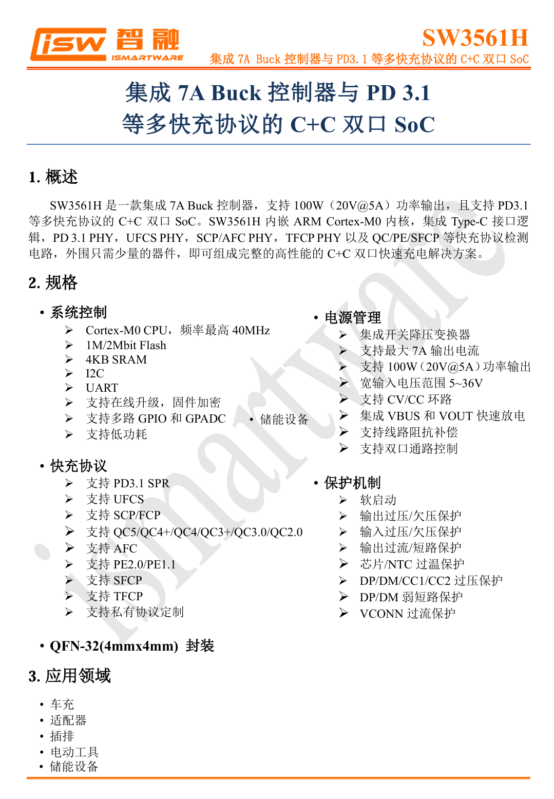
Here is the information about iSmartWare SW3561H.
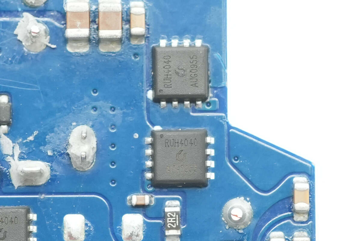
This two synchronous buck MOSFETs are also Ruichips RUH4040.
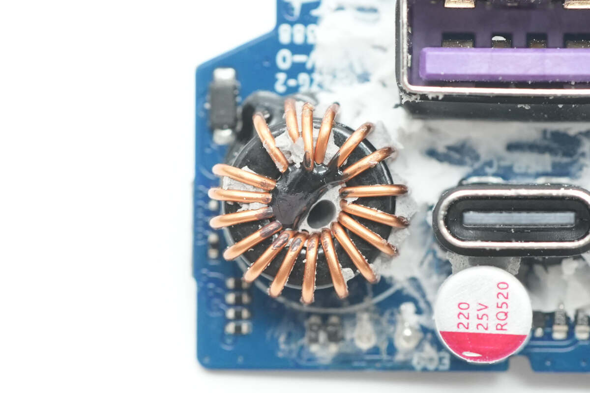
Close-up of the buck inductor.
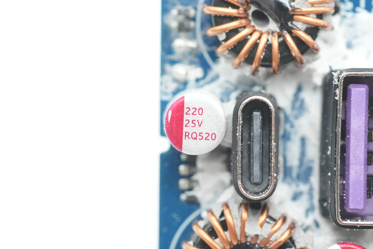
The buck output filtering solid capacitor is from PolyCap, rated at 25V 220μF.
The other capacitor has the same model.
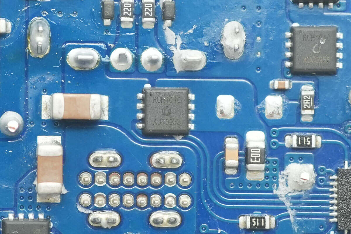
The VBUS MOSFETs for both ports are also Ruichips RUH4040.
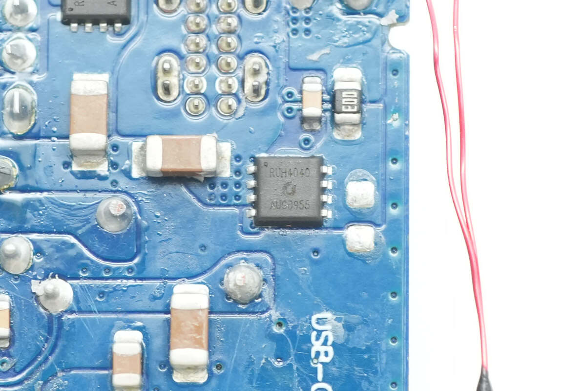
Close-up of another Ruichips RUH4040 VBUS MOSFET.
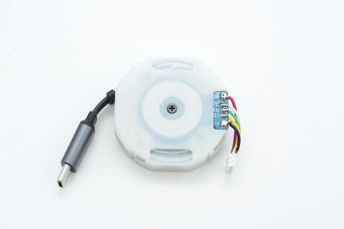
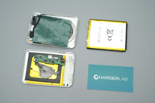
The plastic casing of the retractable cable module is secured by snap-fit clips and a screw.
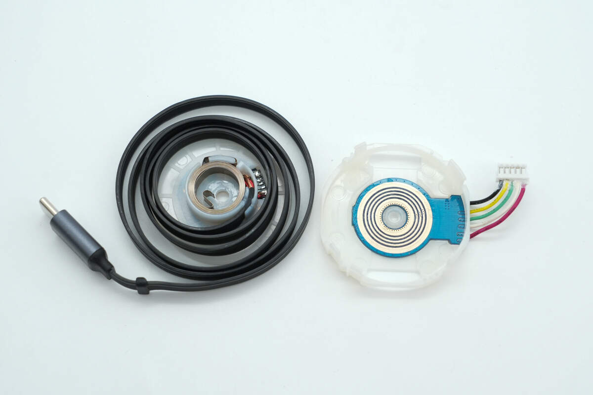
Disassemble the retractable cable module.
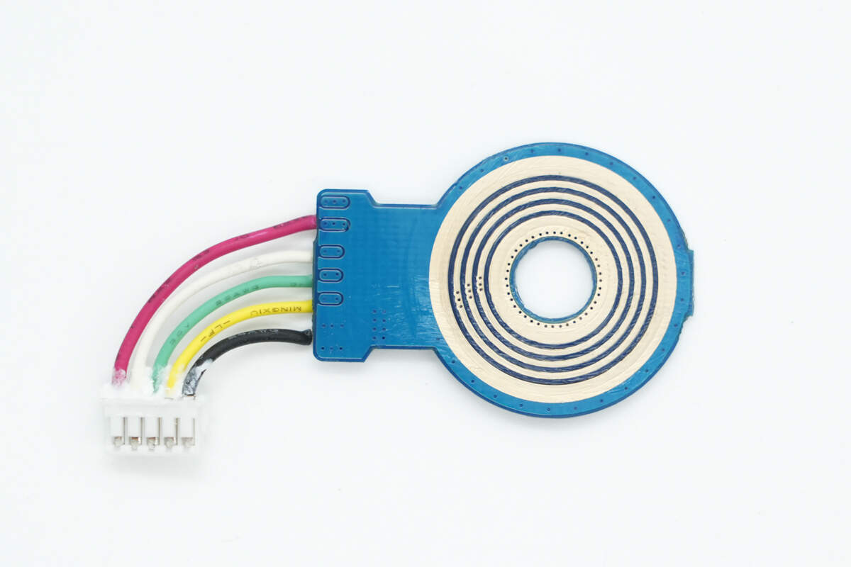
Close-up of the PCB slip ring.
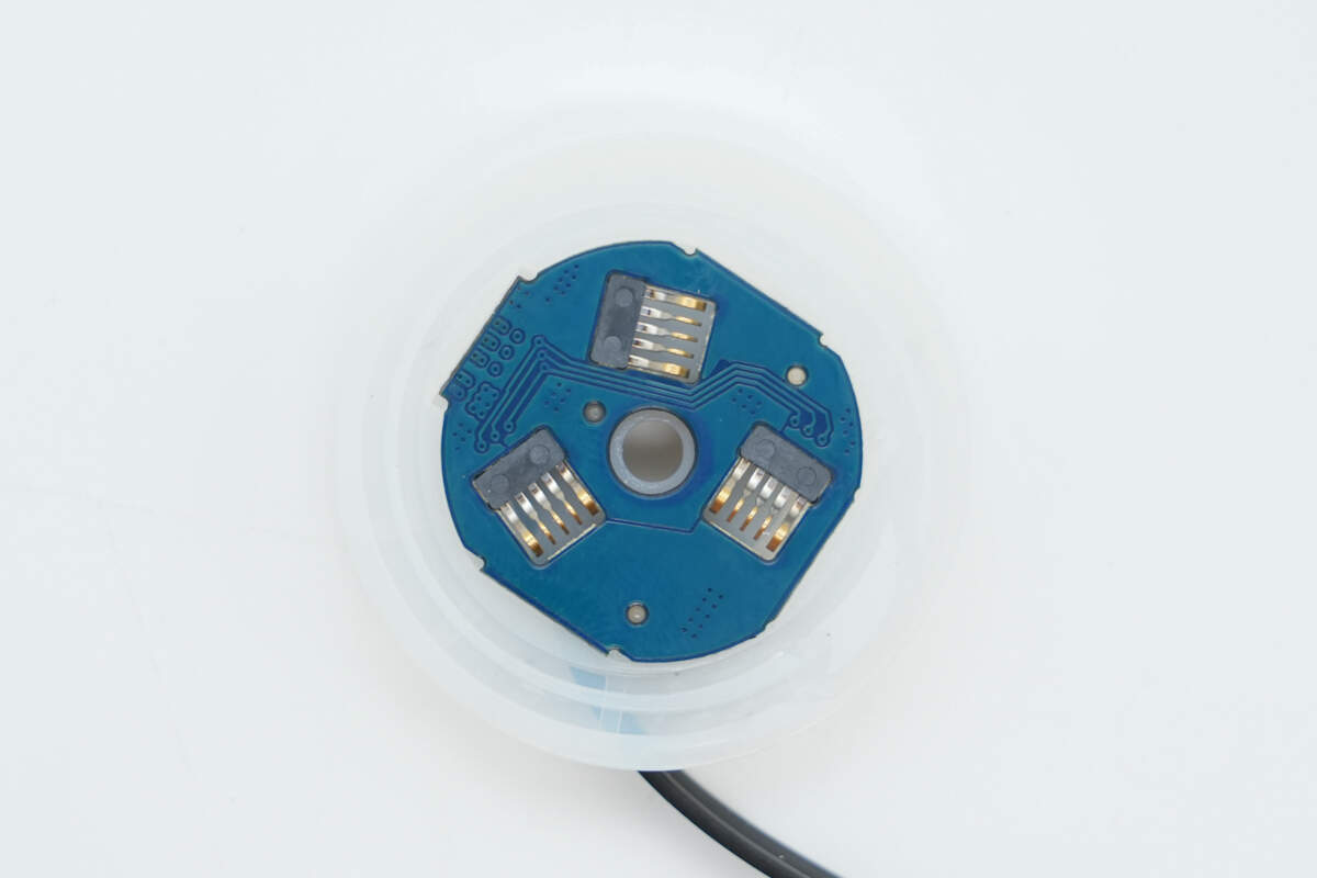
The retractable cable shaft is equipped with three brushes to increase current-carrying capacity.

Well, those are all components of the UGREEN Nexode 65W Charger with Retractable USB-C Cable.
Summary of ChargerLAB
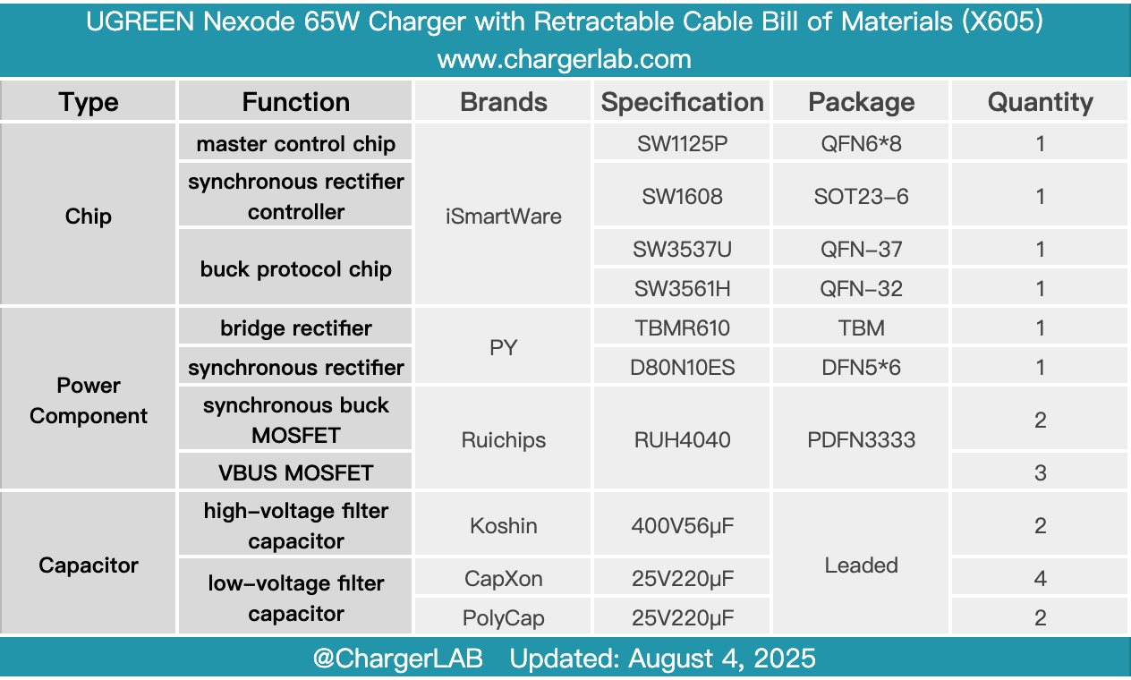
Here is the component list of the UGREEN Nexode 65W Charger with Retractable USB-C Cable for your convenience.
It comes with a 70cm long USB-C retractable cable and features one USB-C and one USB-A port. The retractable cable is strong and durable, resistant to pulling, and has passed tens of thousands of bend tests. It supports over 25,000 extension and retraction cycles, making it highly durable and preventing cable tangling. This design meets the demand for charging multiple devices simultaneously.
After taking it apart, we found that the PCBA module consists of three small PCBs. The power solution is from iSmartWare, using the SW1125P GaN integrated chip paired with the SW1608 synchronous rectifier controller to form a switched-mode power supply with fixed voltage output.
The buck chips used are the iSmartWare SW3537U and SW3561H. The filtering capacitors come from three major brands: Koshin, CapXon, and PolyCap. The entire PCBA module is potting-filled to enhance thermal performance, demonstrating reliable workmanship and quality components.
Related Articles:
1. Teardown of UGREEN USB-C to DisplayPort 8K Cable (CM556)
2. Teardown of CANDYSIGN 160W CoCan Ultra
3. Teardown of Baseus 65W GaN5 Pro Charger (CCGAN65C5)