Introduction
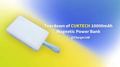
Today, we’ll be taking apart the UGREEN 20000mAh 130W Power Bank. It comes with a built-in USB-C cable, along with one additional USB-C port and one USB-A port, supporting 100W + 30W dual output for a total of 130W. The maximum input power reaches 80W, allowing a full recharge in just about two hours. Inside, it houses SunPower automotive-grade battery cells, which retain over 80% capacity after 800 full charge–discharge cycles. The device is CCC-certified, ensuring reliability and safety.
Next, we’ll conduct a teardown to examine its internal design and components.
Product Appearance
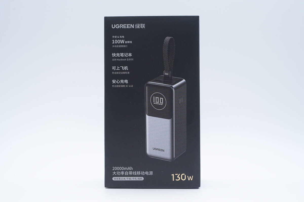
The front of the packaging displays the UGREEN logo, the power bank’s name, its appearance, and key selling points.
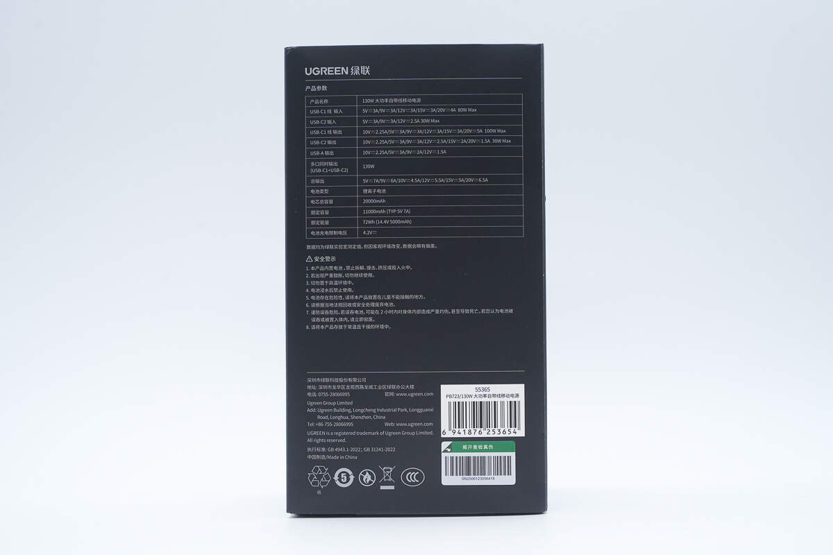
The back of the packaging displays the specification information.
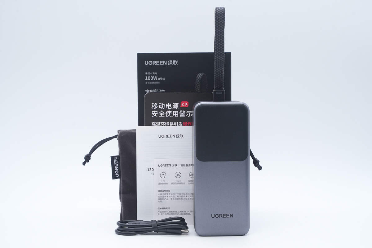
The package includes the power bank, a cable, a storage pouch, and some documents.
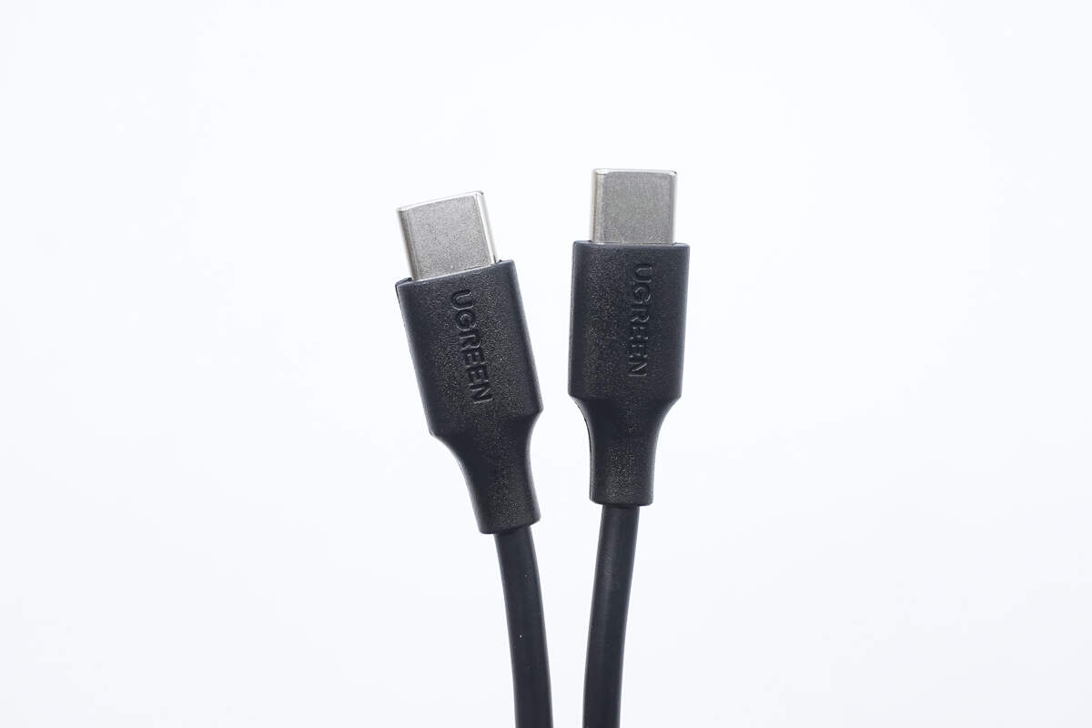
The included cable is a dual USB-C type with a matte finish on the connectors, and the front side features the UGREEN logo.
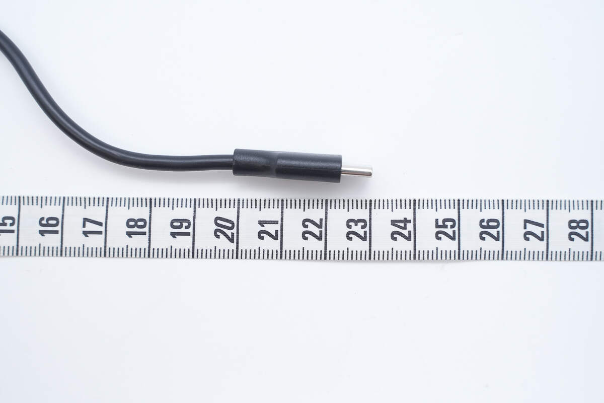
The length of the cable is about 23 cm (9.055 inches).
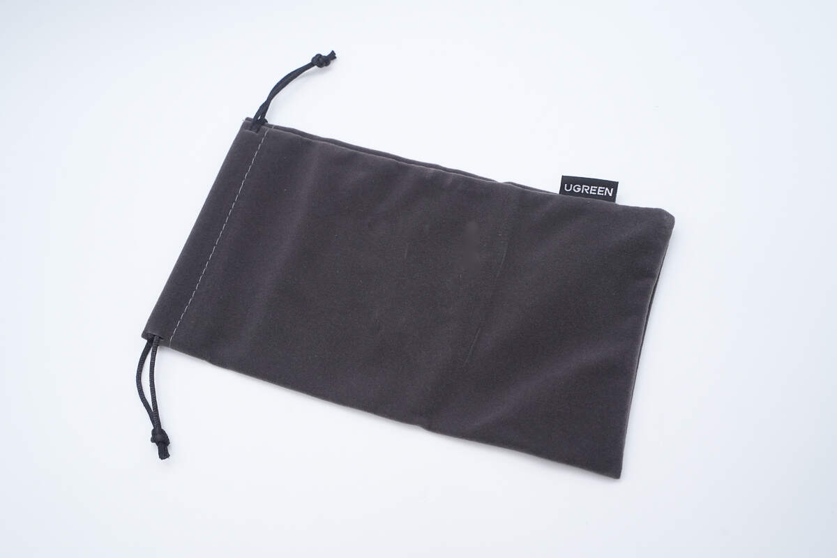
Close-up of the drawstring storage pouch.
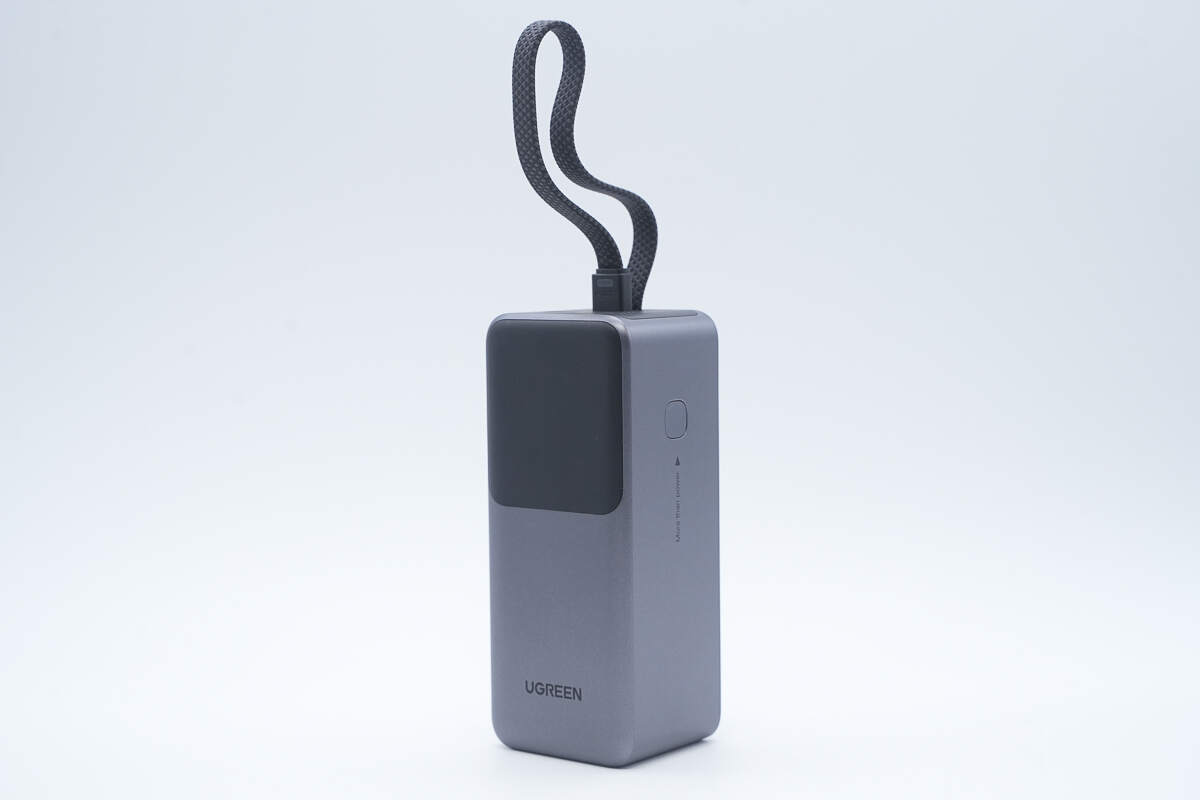
The built-in braided USB-C cable can also be used as a carrying strap.
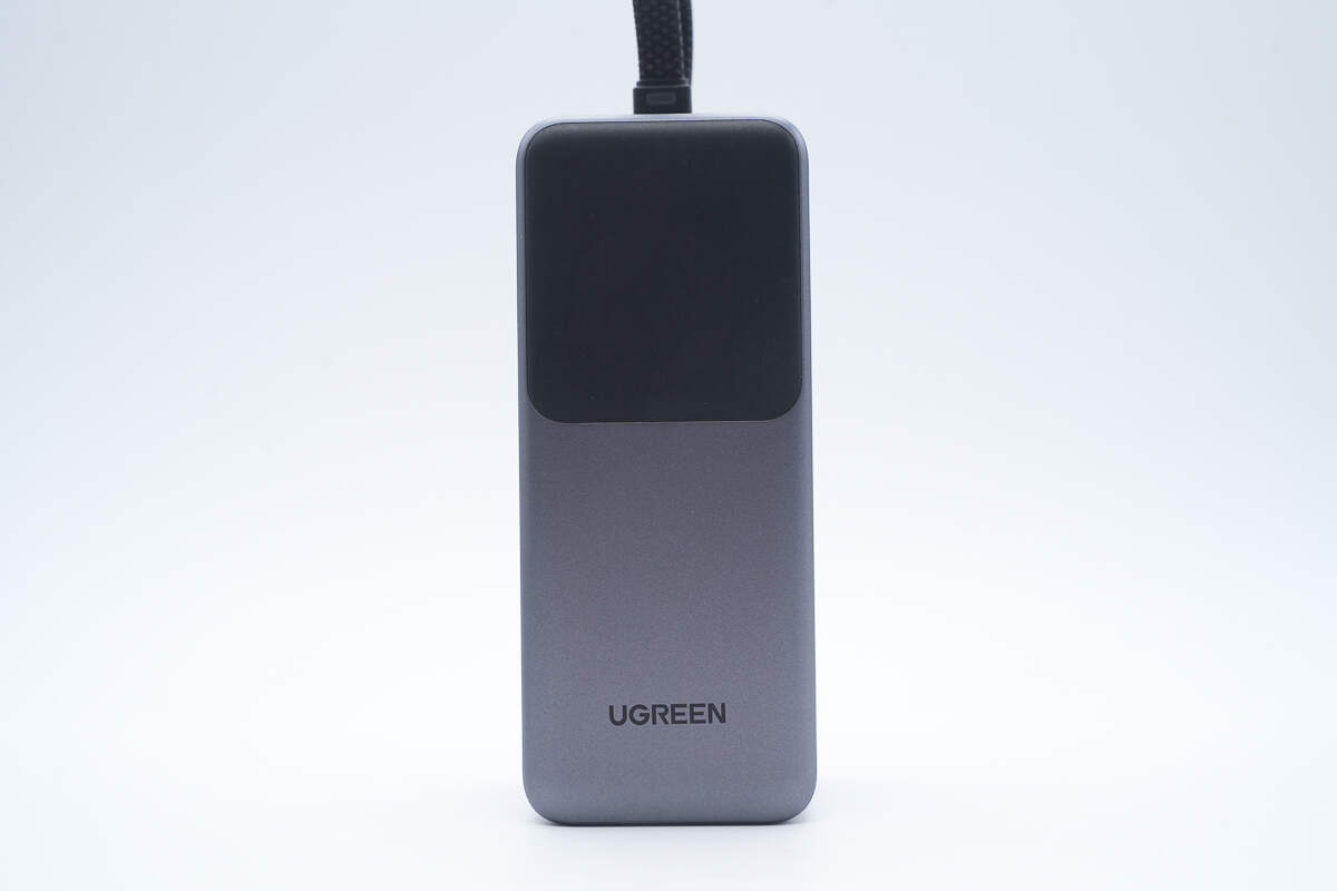
The front features a digital display screen.
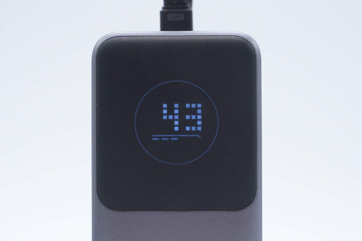
The digital display clearly shows the remaining battery level.
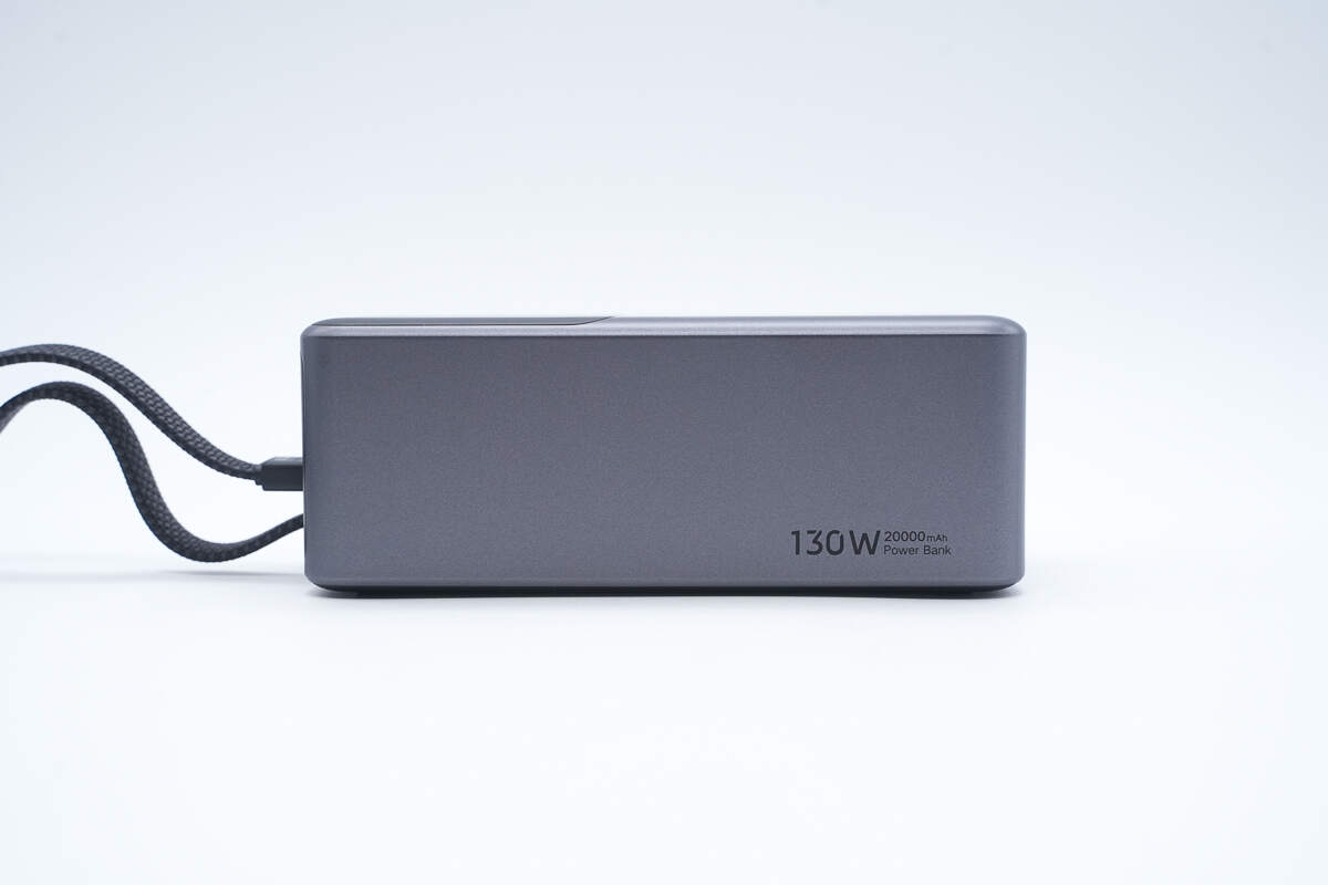
The side is labeled with “130W 20000mAh Power Bank.”
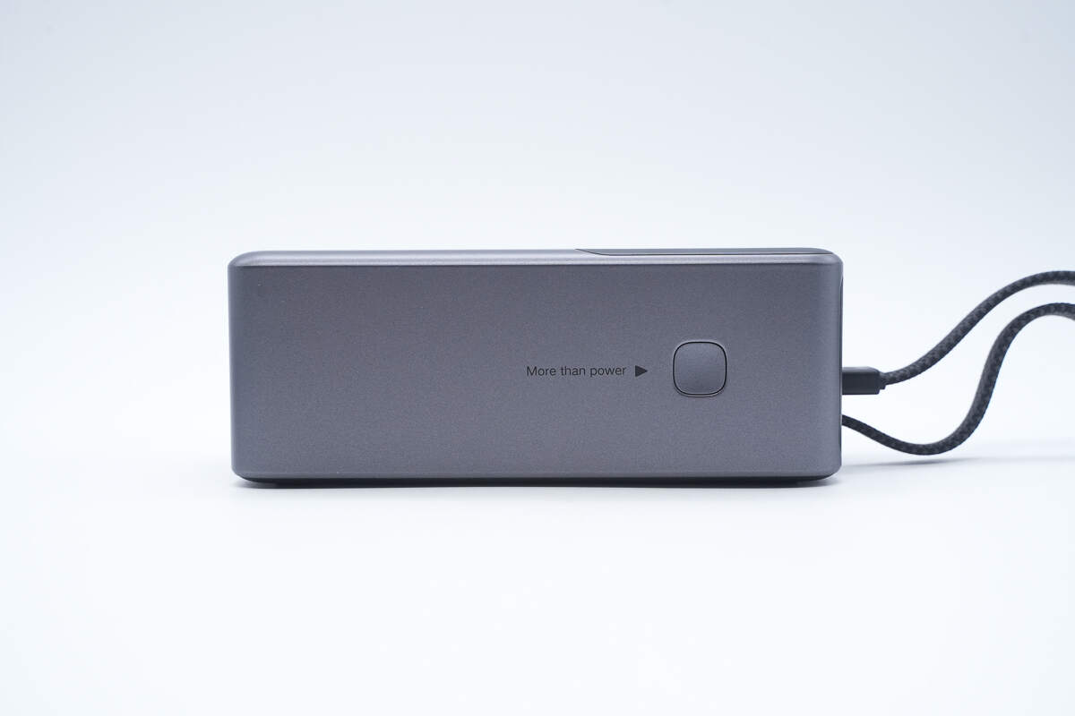
The other side features the power button.
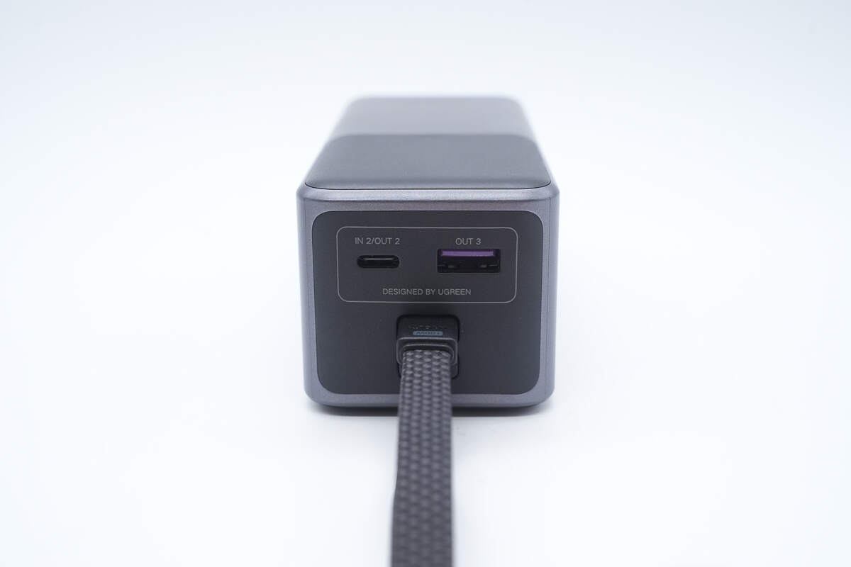
The top is equipped with a USB-C port, a USB-A port, and the cable.
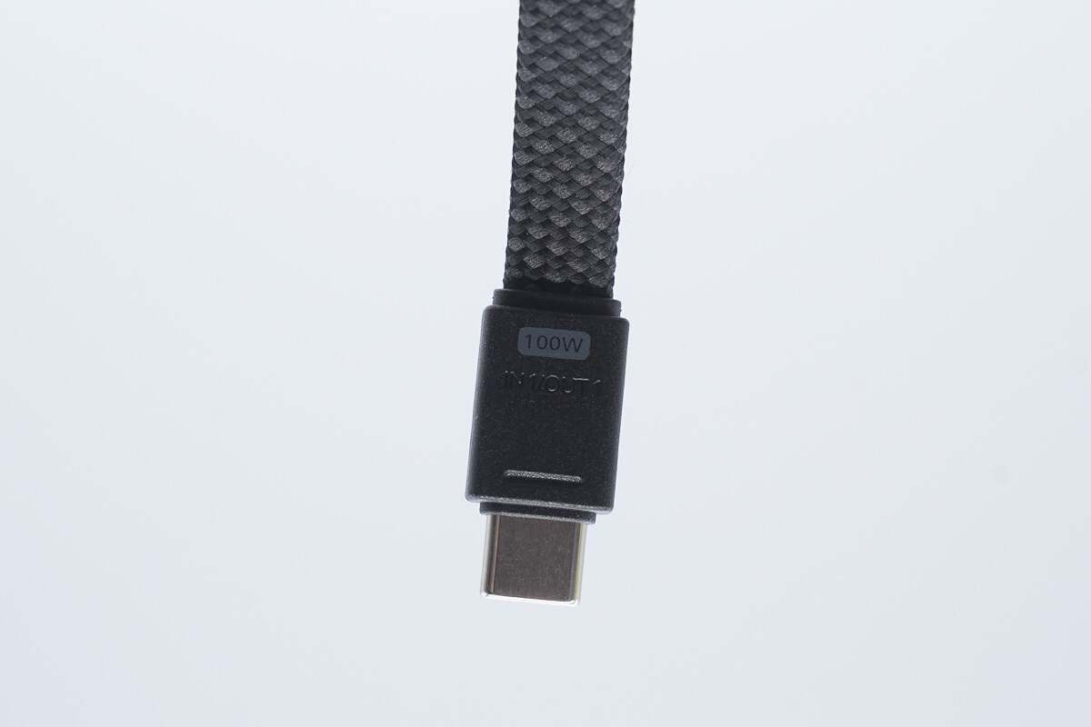
The built-in USB-C cable is flat, with “100W” and “IN 1/OUT 1” markings on the front.
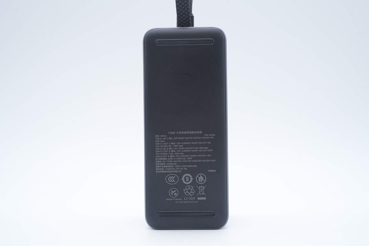
The back has anti-slip strips and displays the specification information.
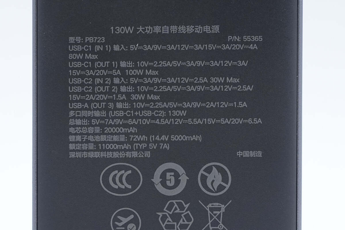
Model: PB723
P/N: 55365
USB-C1 (IN1) Input: 5V 3A, 9V 3A, 12V 3A, 15V 3A, 20V 4A, 80W Max
USB-C1 (OUT1) Output: 5V 3A, 9V 3A, 10V 2.25A, 12V 3A, 15V 3A, 20V 5A, 100W Max
USB-C2 (IN2) Input: 5V 3A, 9V 3A, 12V 2.5A, 30W Max
USB-C2 (OUT2) Output: 5V 3A, 9V 3A, 10V 2.25A, 12V 2.5A, 15V 2A, 20V 1.5A, 30W Max
USB-A (OUT3) Output: 5V 3A, 9V 2A, 10V 2.25A, 12V 1.5A
Simultaneous Multi-Port Output (USB-C1 + USB-C2): 130W
Total Output: 5V 7A, 9V 6A, 10V 4.5A, 12V 5.5A, 15V 5A, 20V 6.5A
Total Battery Capacity: 20000mAh
Lithium-Ion Battery Rated Energy: 72Wh (14.4V 5000mAh)
Rated Capacity: 11000mAh (TYP 5V 7A)
CCC Certified, Certificate No.: 2025010914760320, approved for air travel.
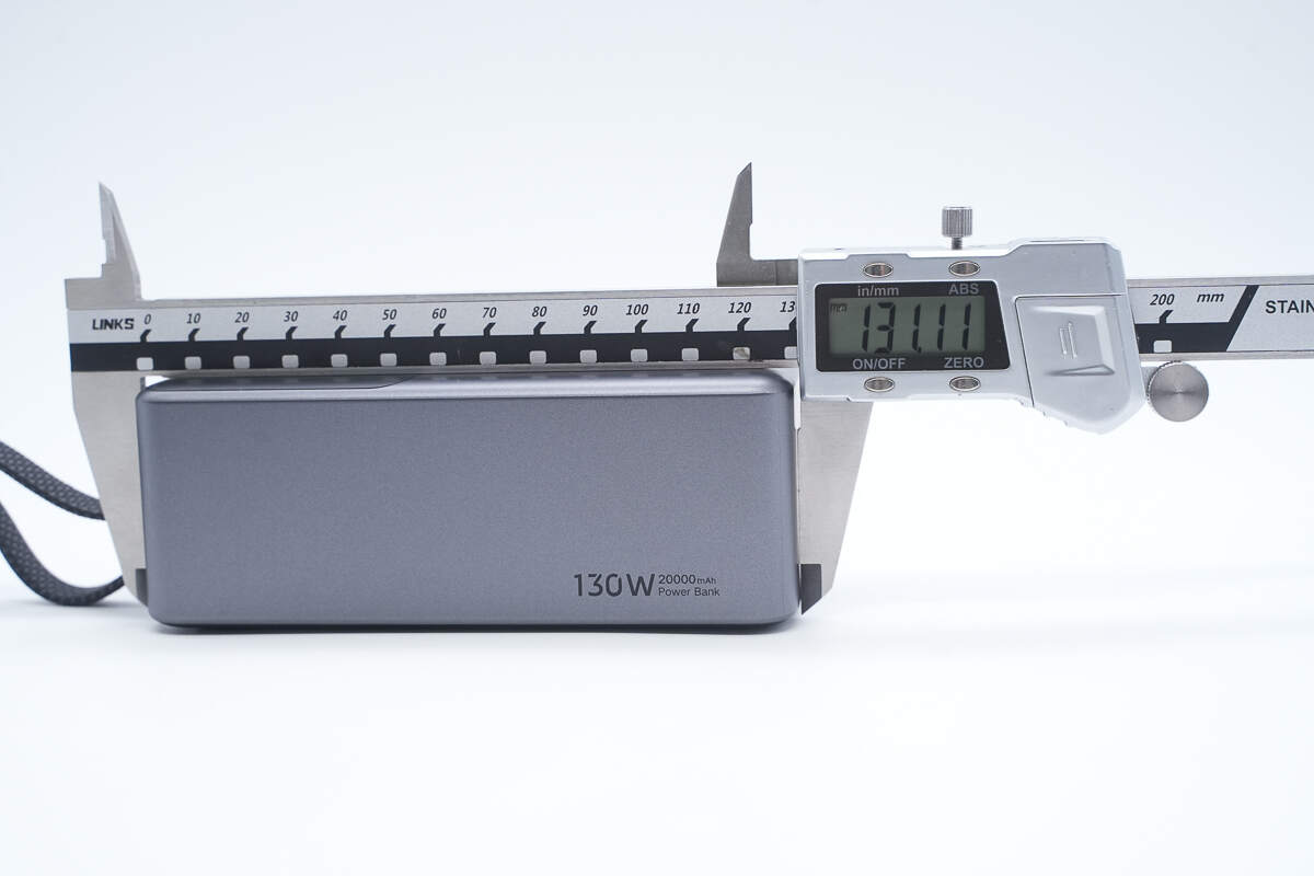
The length of the power bank is about 131.1 mm (5.16 inches).
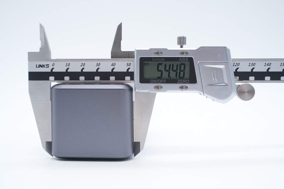
The width is about 54.5 mm (2.15 inches).
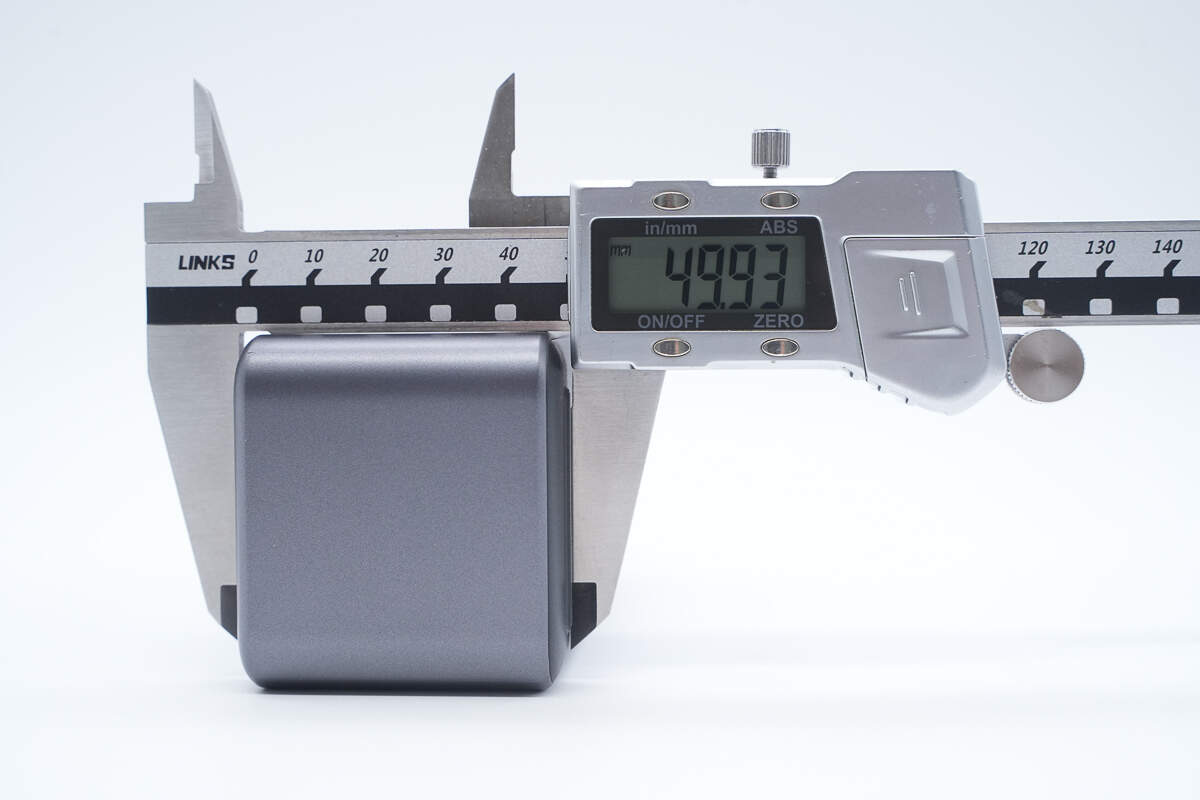
The thickness is about 50 mm (1.97 inches).
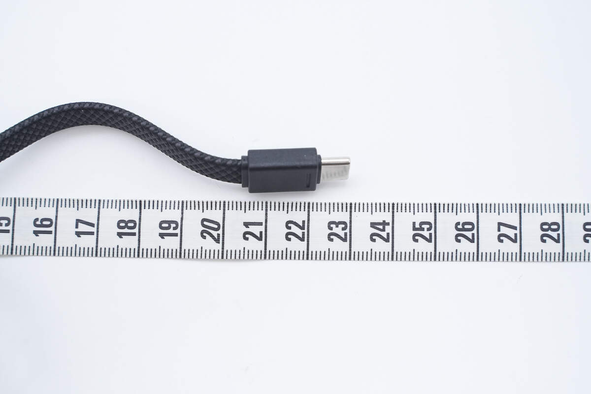
The length of the cable is about 23 cm (9.055 inches).
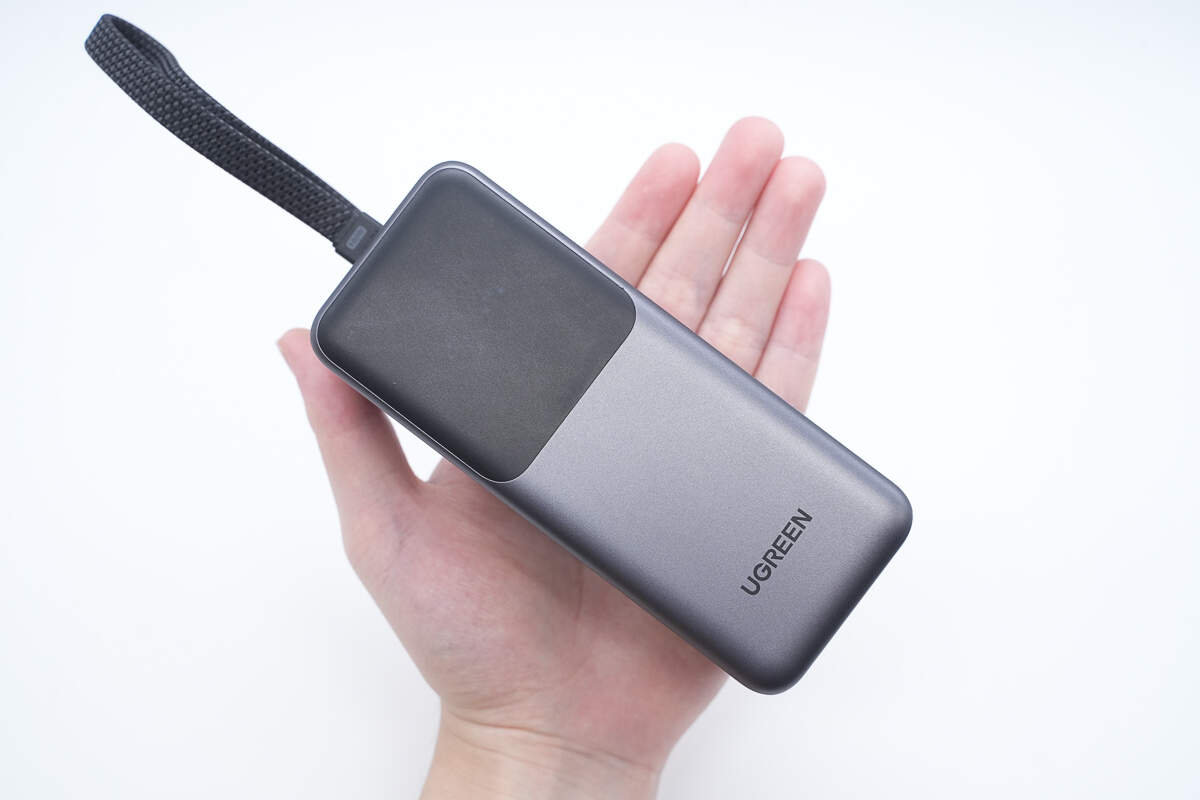
That's how big it is in the hand.
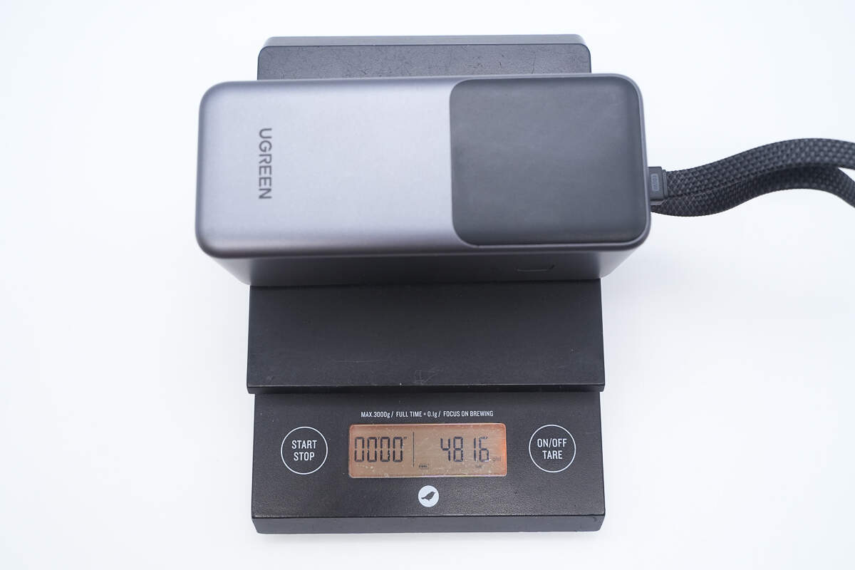
The weight is about 482 g (17 oz).
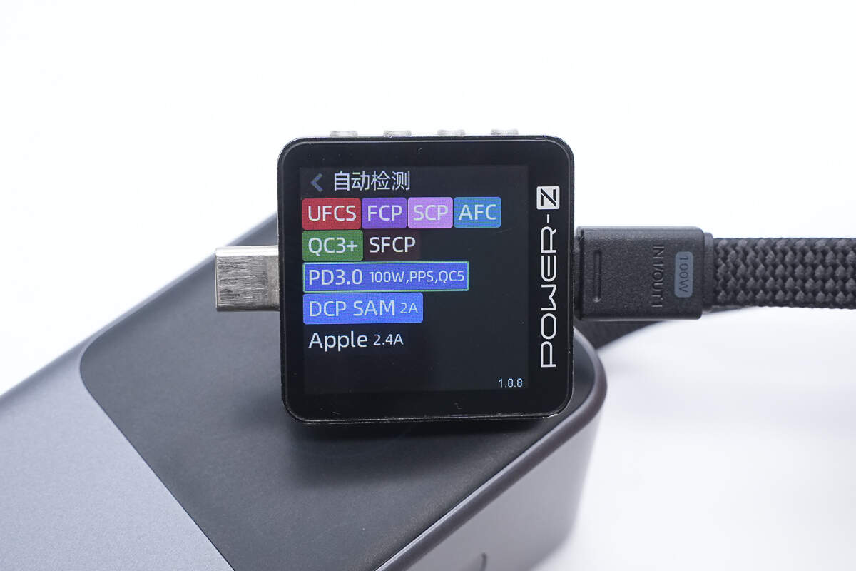
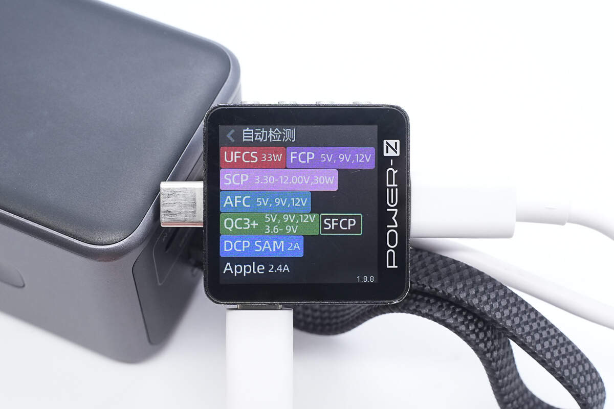
ChargerLAB POWER-Z KM003C shows that the USB-C cable supports UFCS, FCP, SCP, AFC, QC3+/5, SFCP, PD3.0, PPS, DCP, SAM 2A, and Apple 2.4 charging protocols.

And it has five fixed PDOs of 5V3A, 9V3A, 12V3A, 15V3A, and 20V5A. It has one set of PPS, which is 5-21V5A.
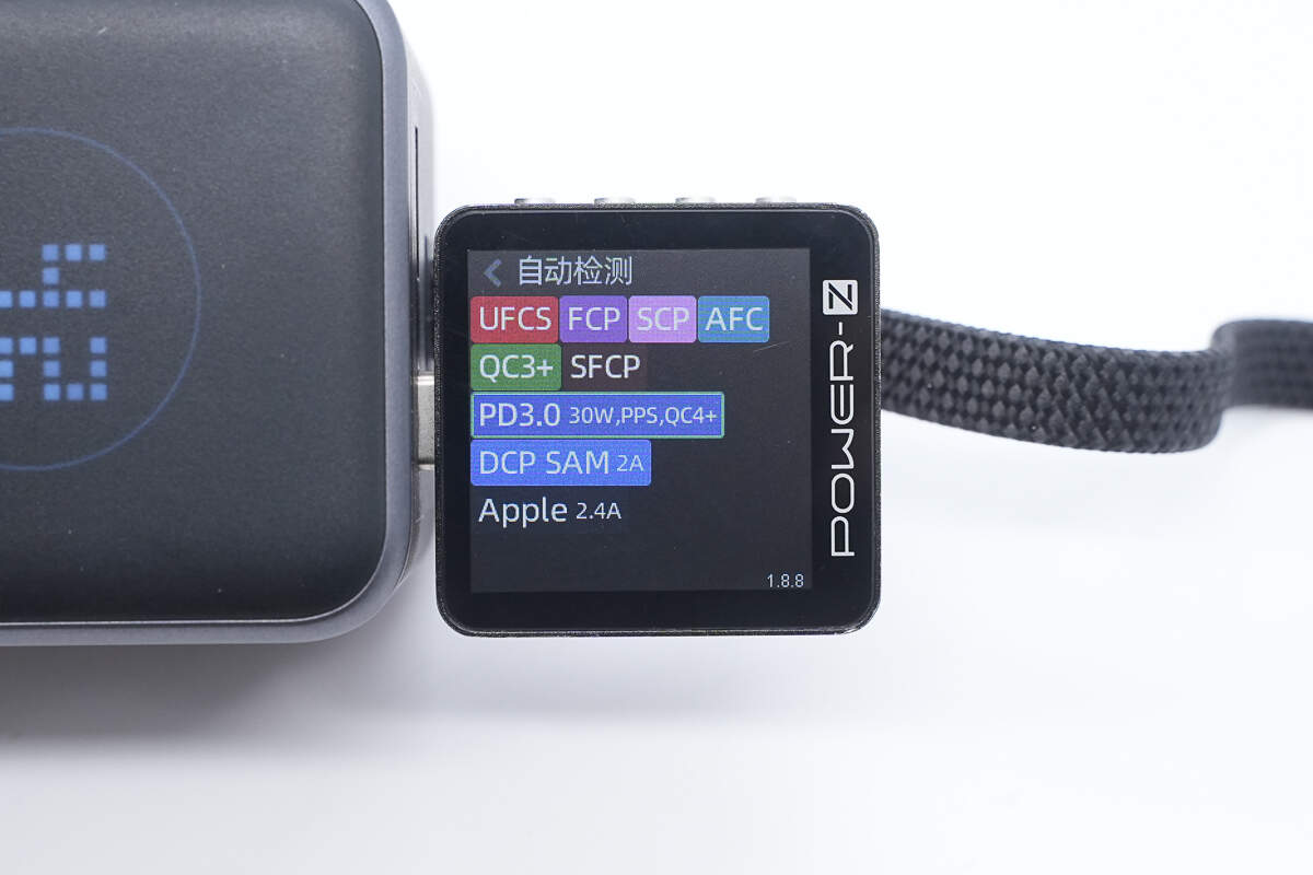
The USB-C port supports UFCS, FCP, SCP, AFC, QC3+/4+, SFCP, PD3.0, PPS, DCP, SAM 2A, and Apple 2.4A charging protocols.
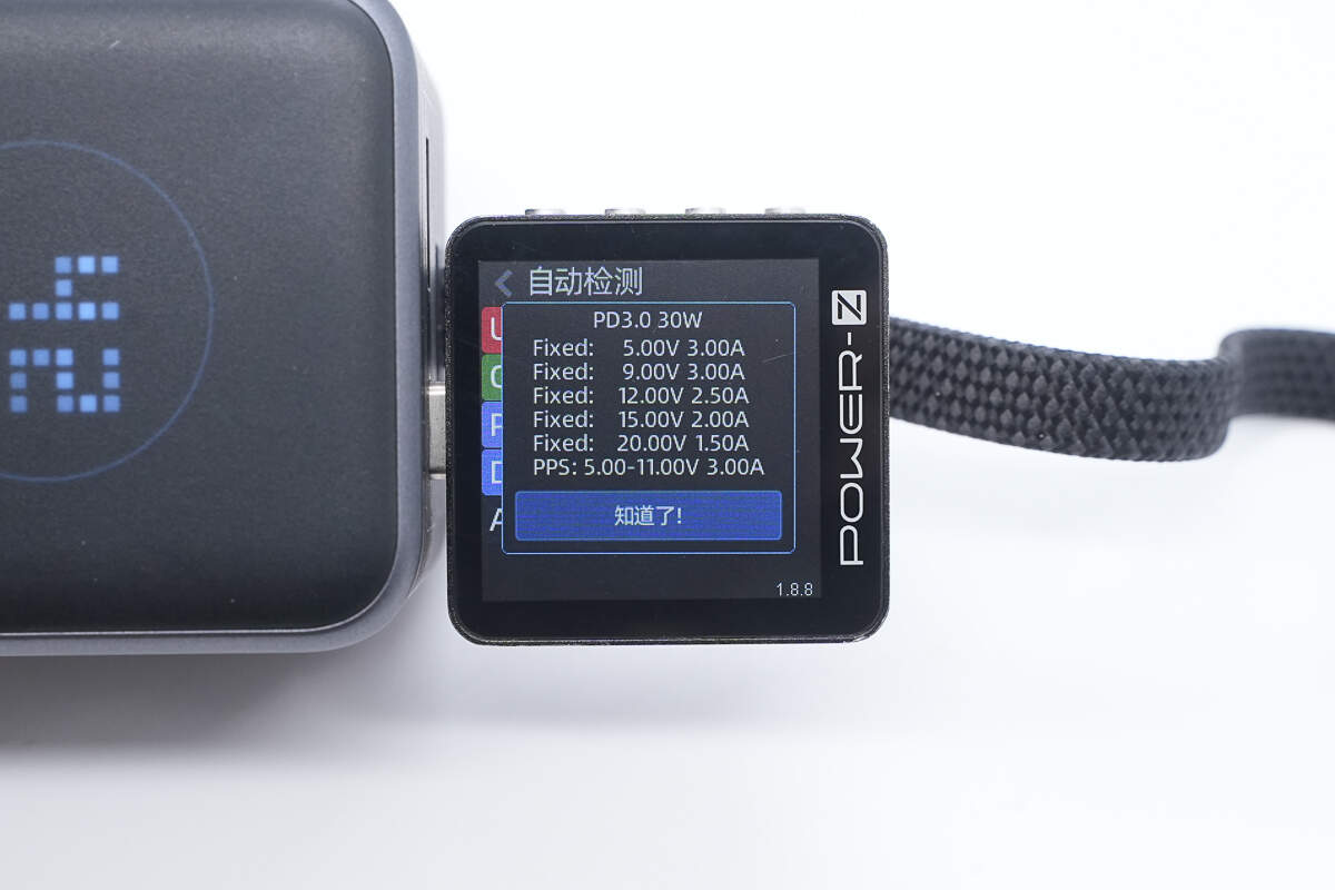
And it has five fixed PDOs of 5V3A, 9V3A, 12V2.5A, 15V2A, and 20V1.5A. It has one set of PPS, which is 5-11V3A.
The USB-A port supports UFCS, FCP, SCP, AFC, QC3+, SFCP, DCP, SAM 2A, and Apple 2.4A charging protocols.
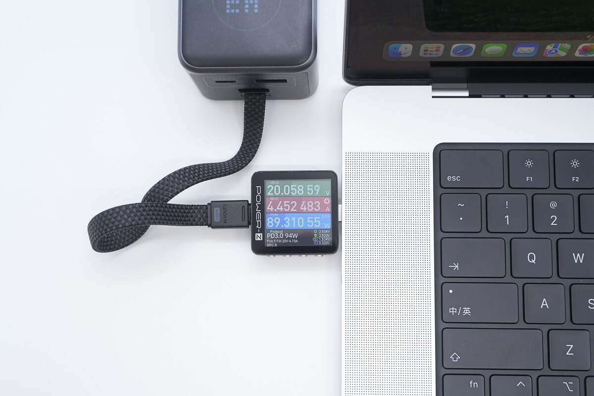
Using the built-in cable to charge a MacBook Pro 16-inch M4 Pro, the charging power is about 89.3 W.
Teardown
Next, let's take it apart to see its internal components and structure.
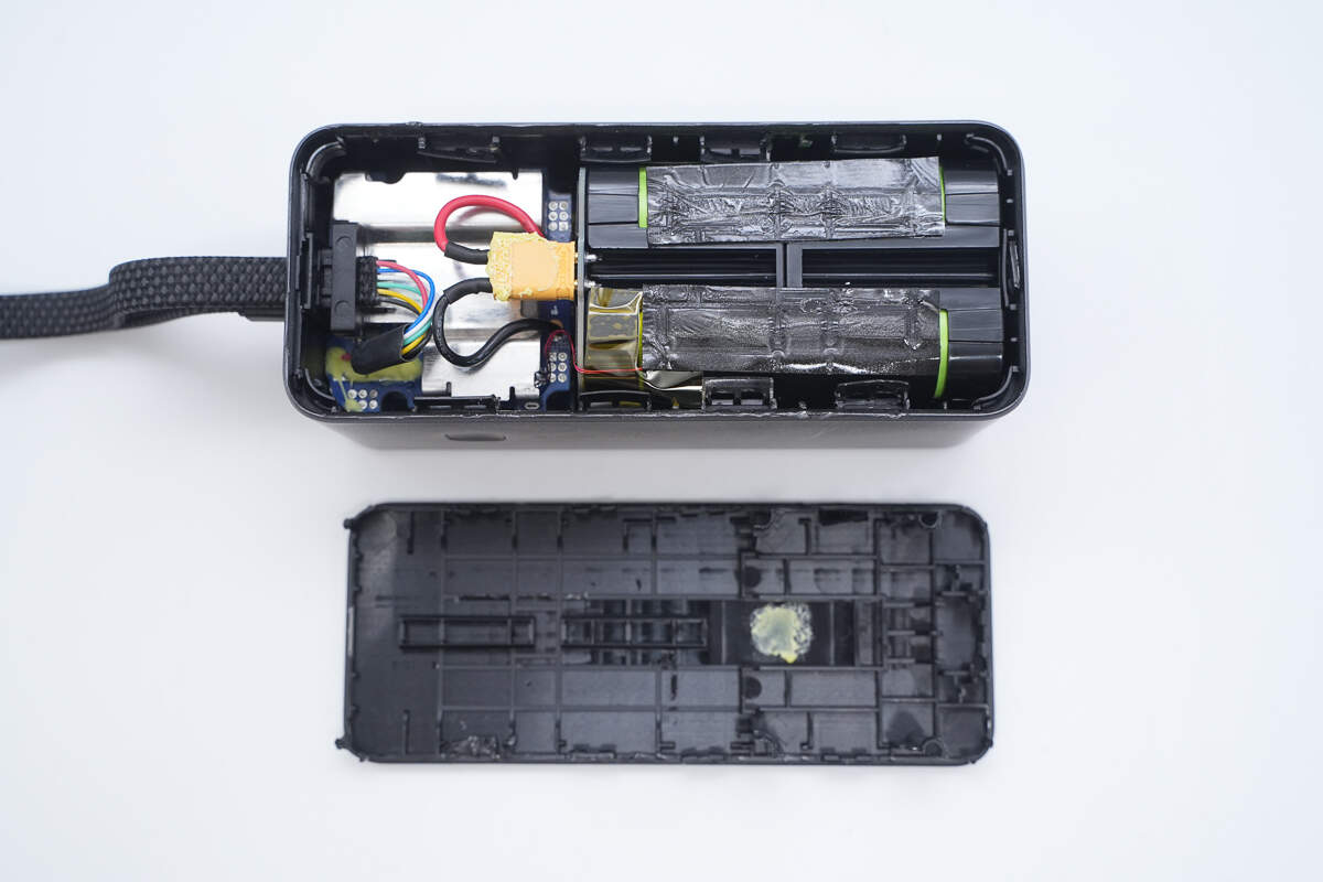
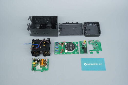
First, pry open the back cover along the seams of the casing.
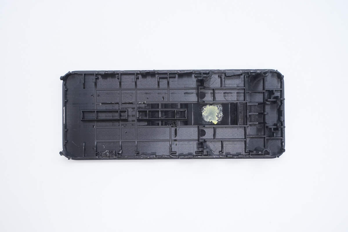
The back cover is secured with ultrasonic welding and clips.
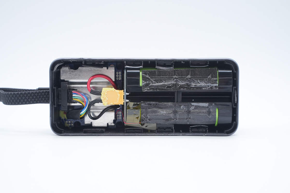
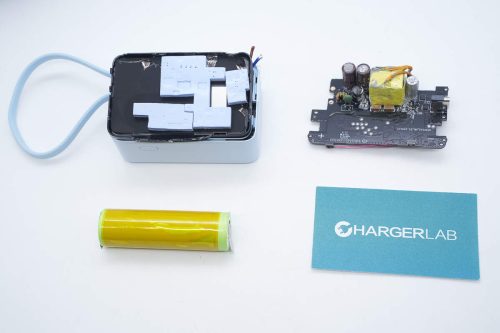
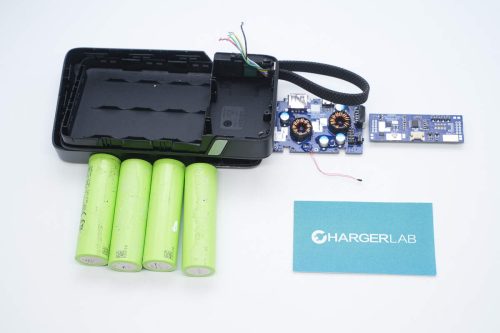
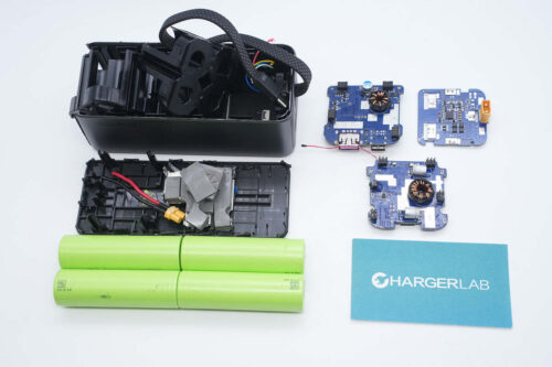
Inside, there is a PCBA module and a battery pack.
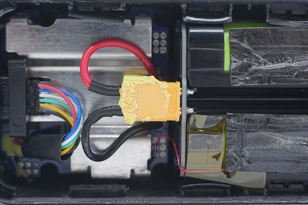
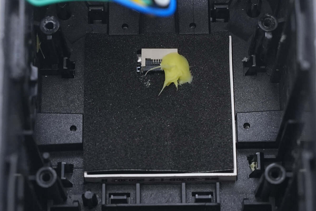
The battery pack is connected via an XT30 connector, which is reinforced with adhesive. The thermistor is secured to the battery cells using high-temperature tape.
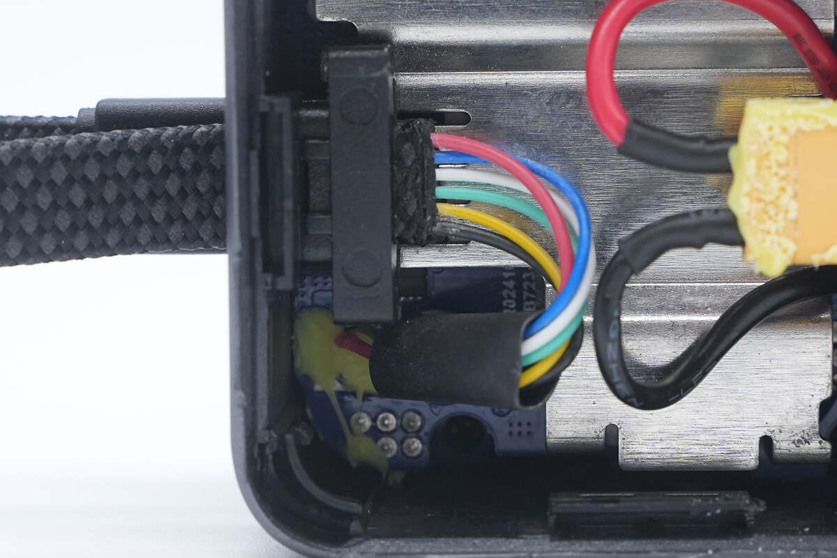
The built-in cable is soldered to the PCBA module.
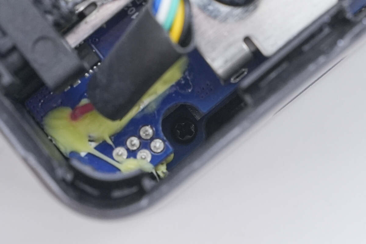
The PCBA module is secured with screws.
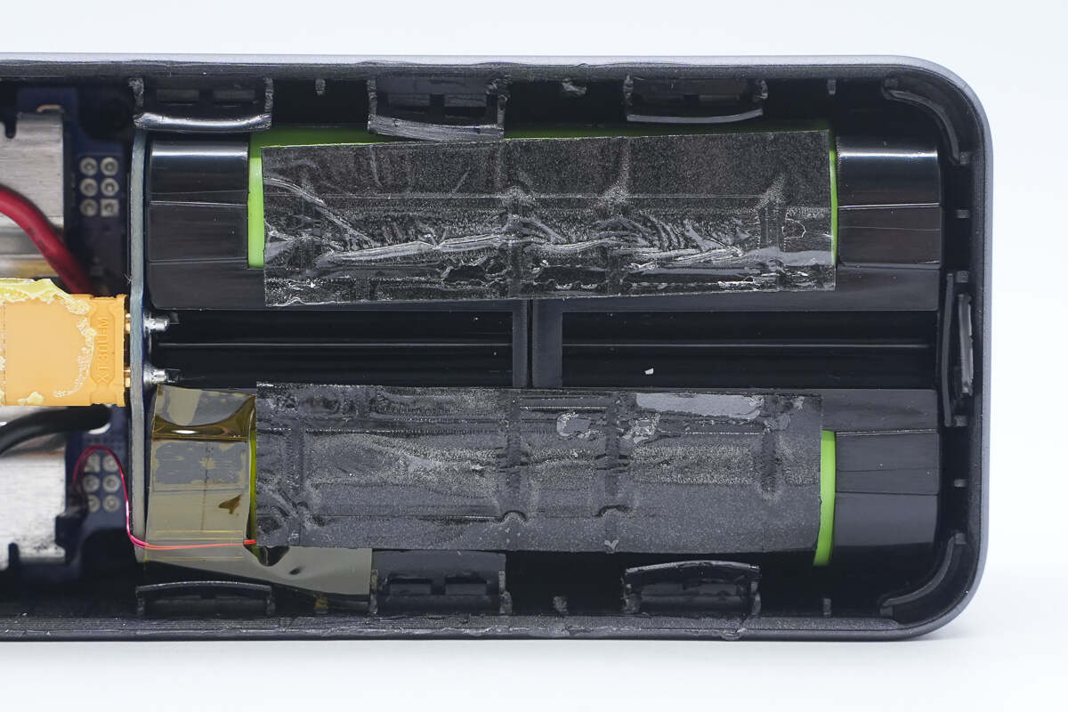
The battery pack is cushioned with adhesive foam.
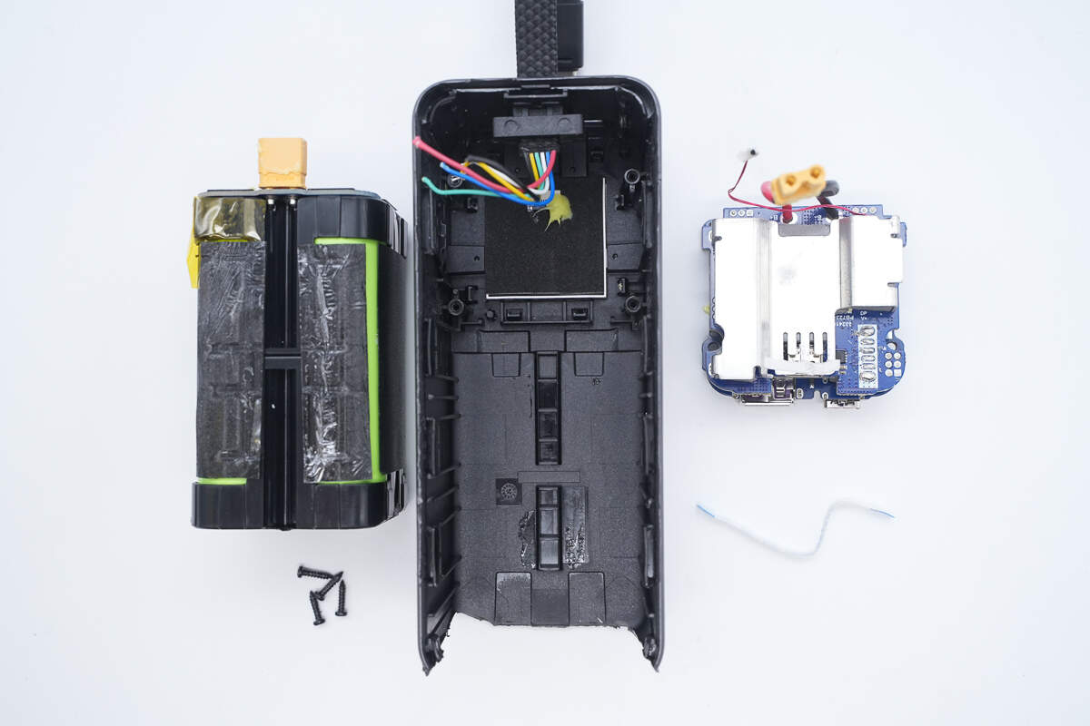
Remove the PCBA module and the battery pack.
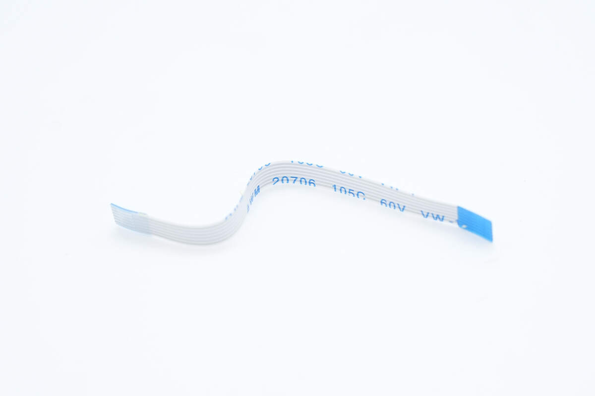
Close-up of the ribbon cable connecting the LCD screen.
The back of the LCD screen has a ribbon cable socket.
The battery pack is secured with a plastic frame, with mylar insulation sheets applied on the sides.
The other side is also lined with cushioning foam and mylar sheets.
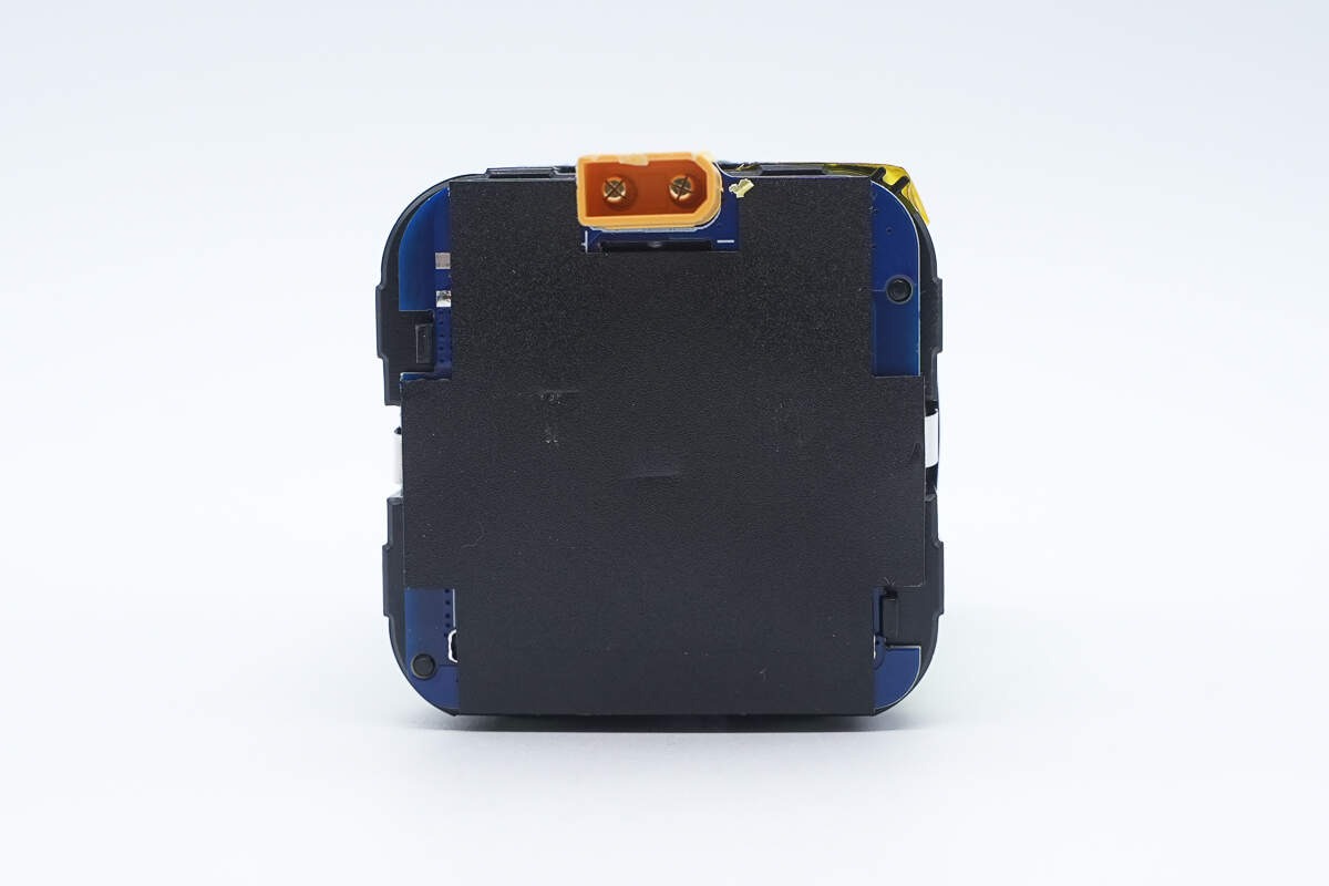
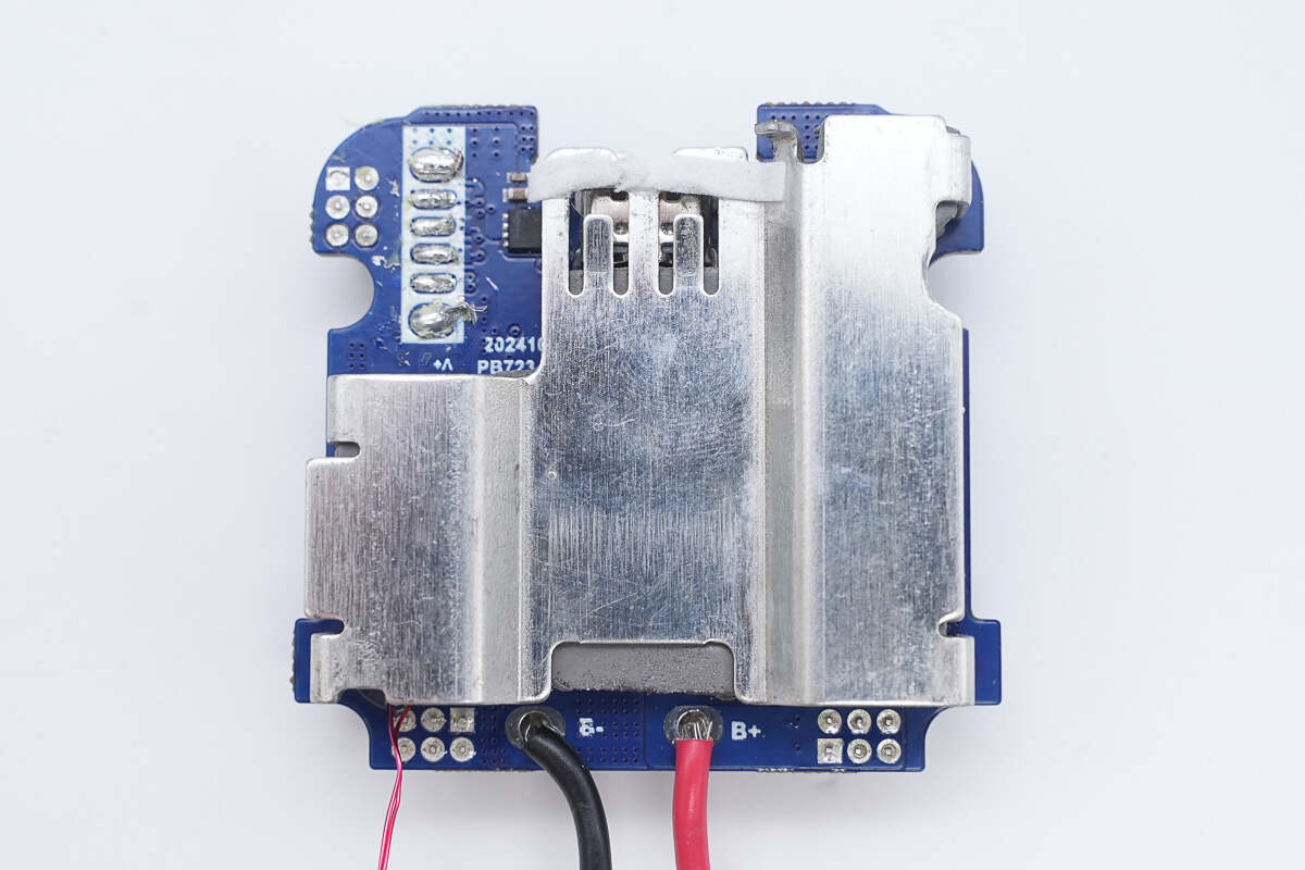
The battery protection PCB is insulated with a mylar sheet covering.
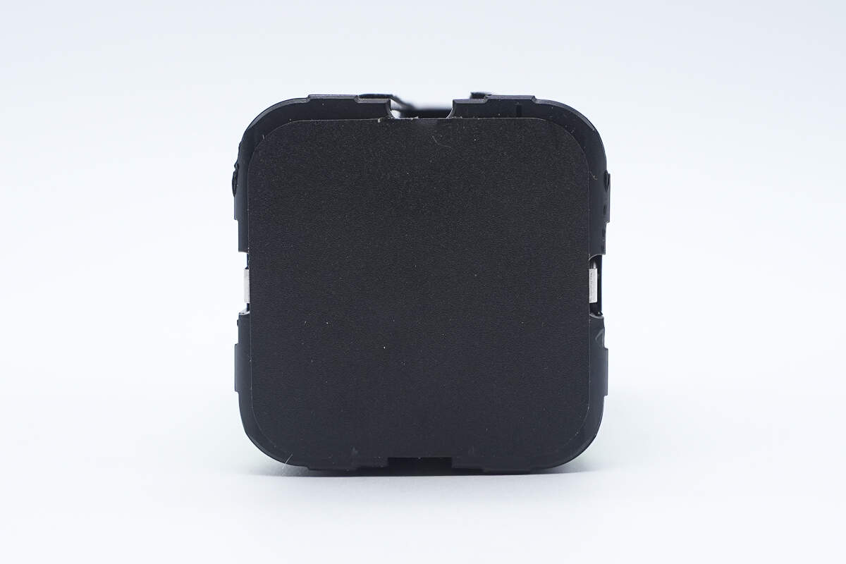
The other side of the battery pack is also insulated with mylar sheets.
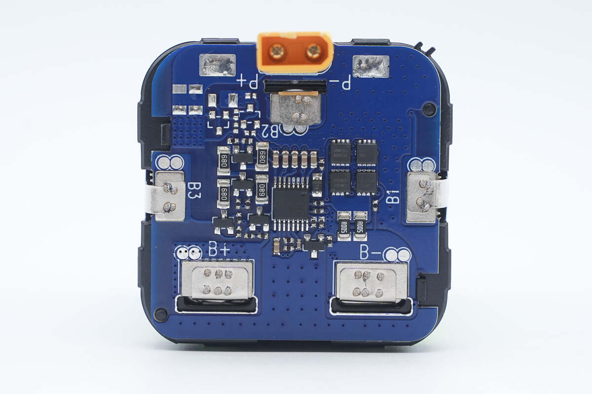
The protection PCB includes a battery protection chip, battery protection MOSFETs, and a balancing circuit.
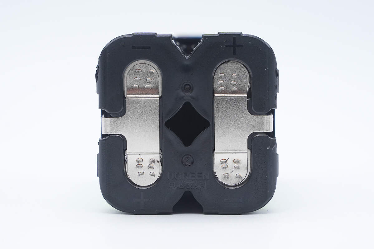
The battery cells are secured with a plastic frame and connected via nickel strips spot welding.
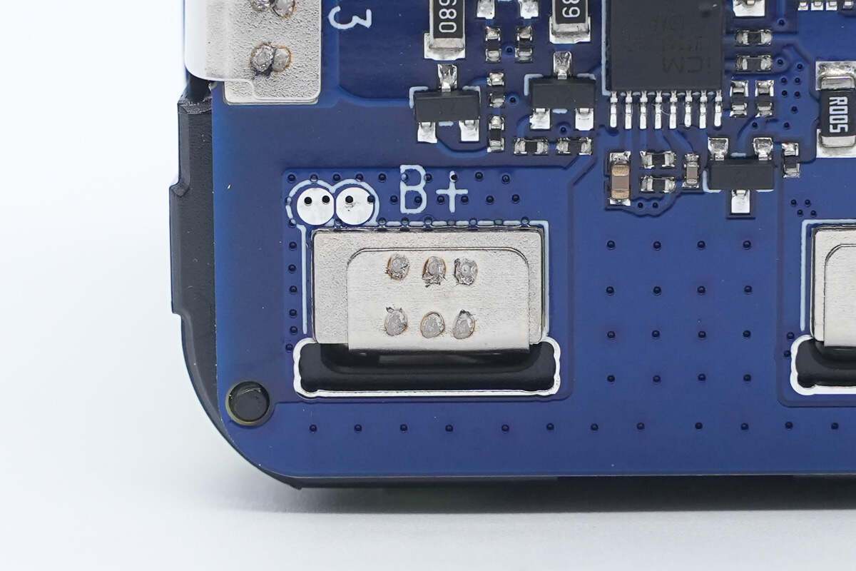
The battery pack is connected to the protection PCB via spot welding.
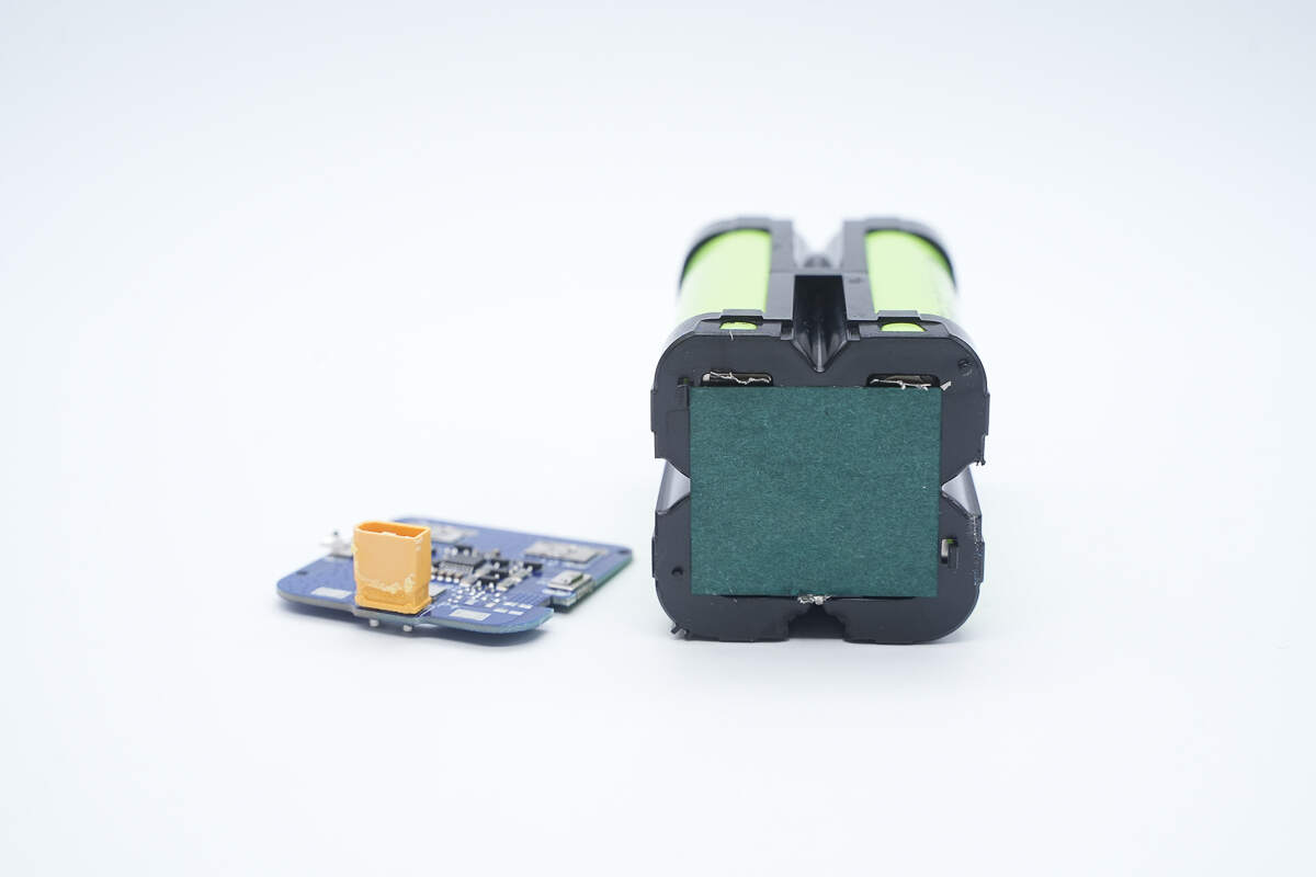
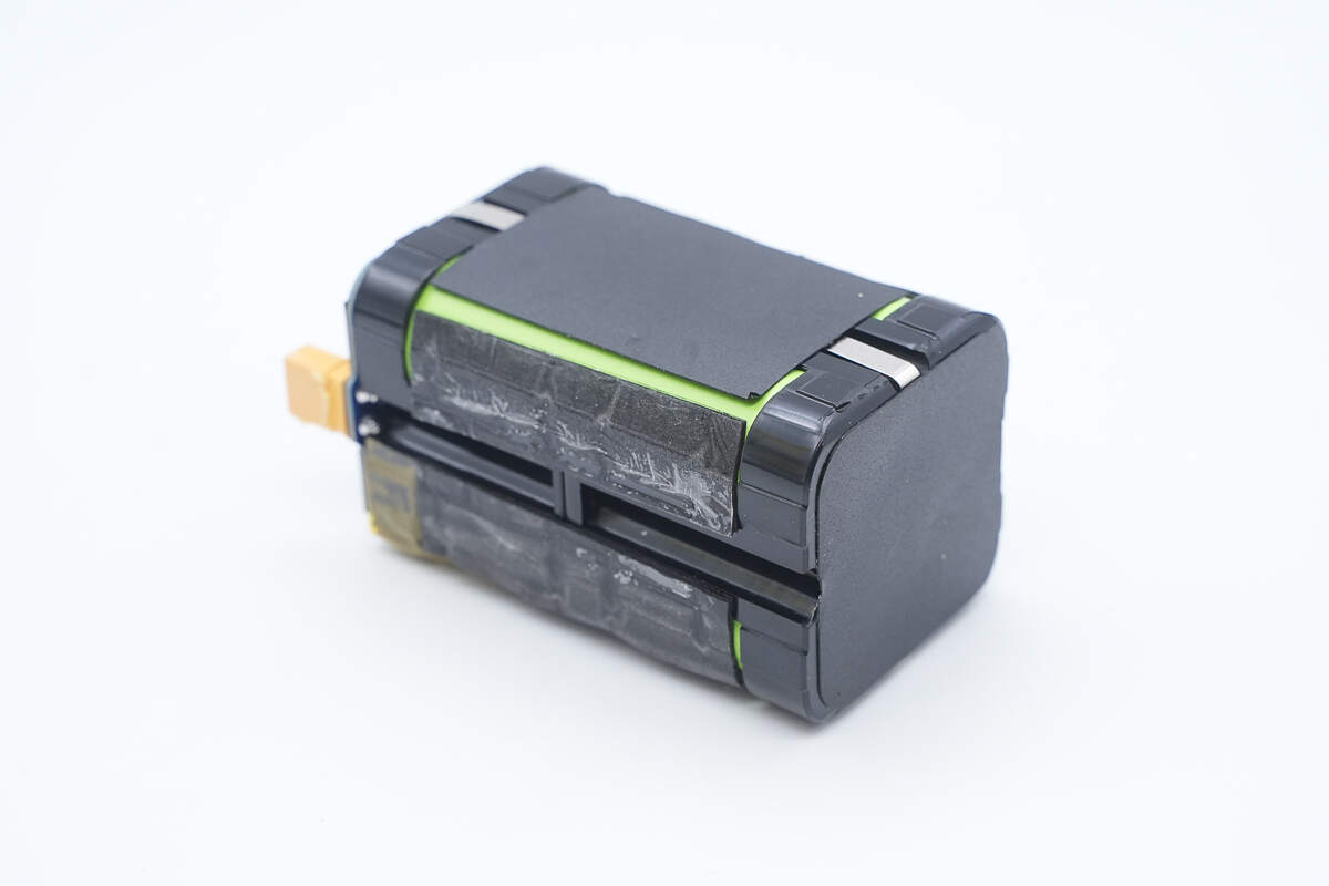
After removing the protection PCB, the back is insulated with oiled paper.
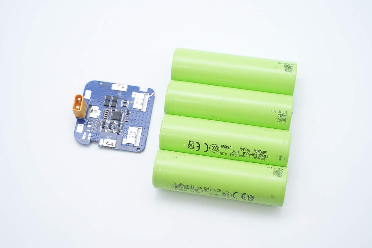
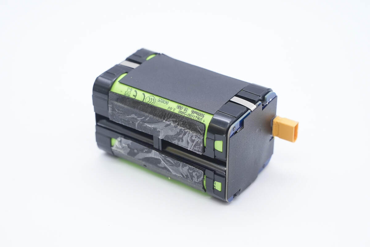
Overview of the protection PCB and the four 21700 battery cells.
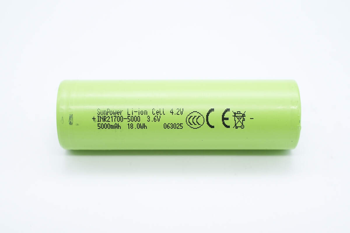
The battery cells are model INR21700-5000 from SunPower, with a nominal voltage of 3.6 V, a nominal capacity of 5000 mAh, and an energy rating of 18 Wh. The charge cut-off voltage is 4.2 V, and the cells are CCC and CE certified.
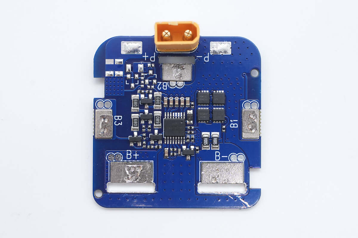
The front of the protection board has the battery protection chip in the center, the balancing circuit on the left, and the battery protection MOSFETs along with the current-sensing resistor on the right.
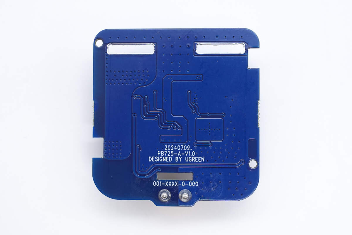
The back of the protection PCB has no components.
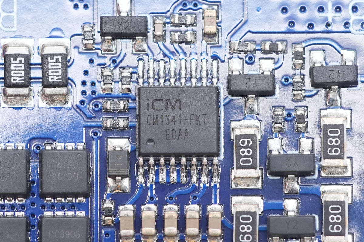
The battery protection chip is from ICM, model CM1341-FKT. It is a protection chip designed for 4-series lithium-ion or lithium iron phosphate batteries, featuring built-in high-precision voltage and current detection circuits.
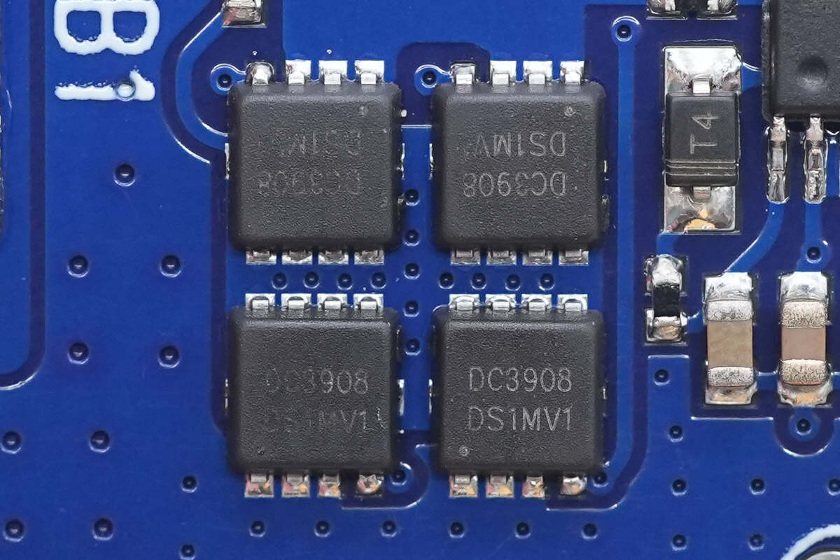
The battery protection MOSFETs are from POTENS, model PDC3908Z. They are NMOS devices with a voltage rating of 30 V, an on-resistance of 7.8 mΩ, and come in a PPAK 3×3 package.
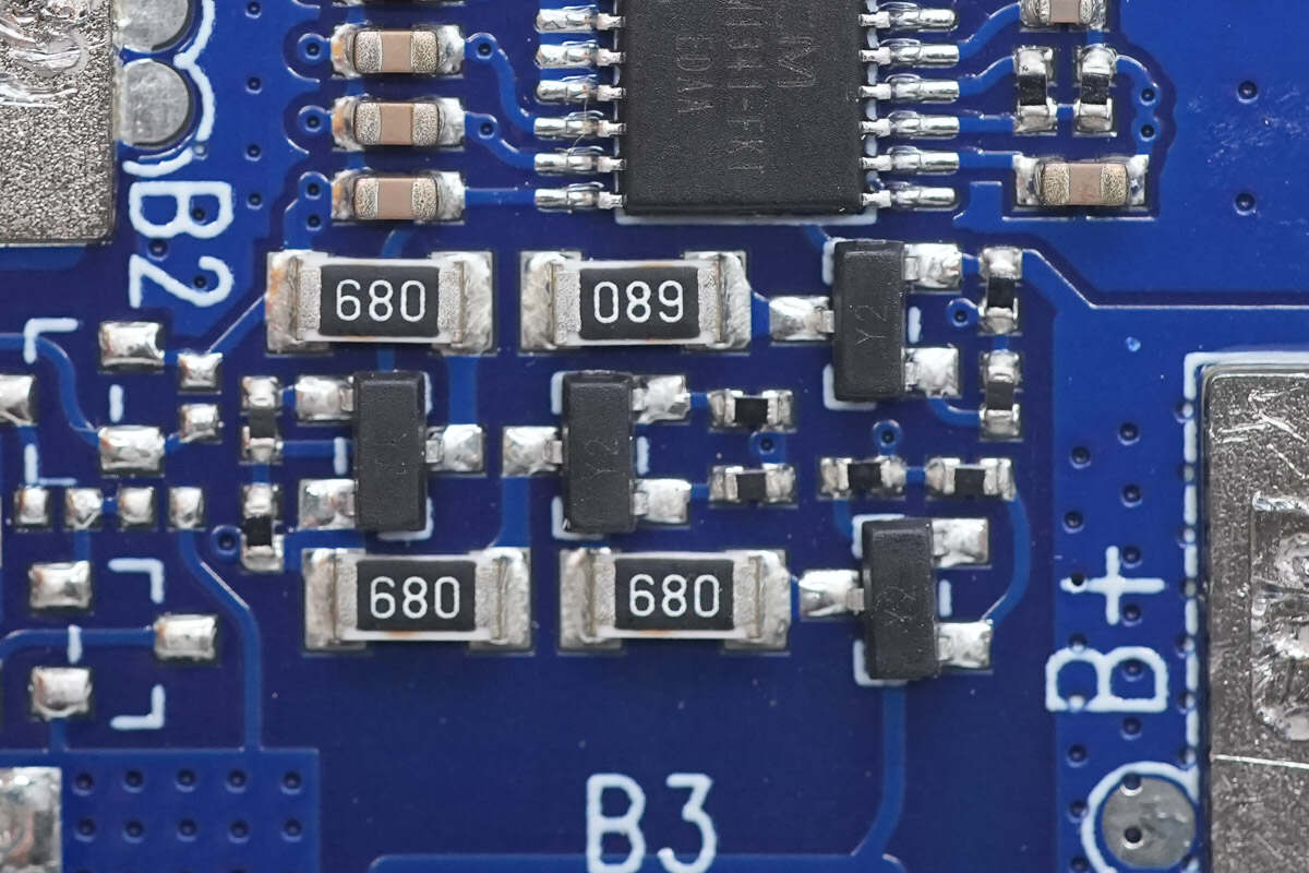
Close-up of the balancing circuit.
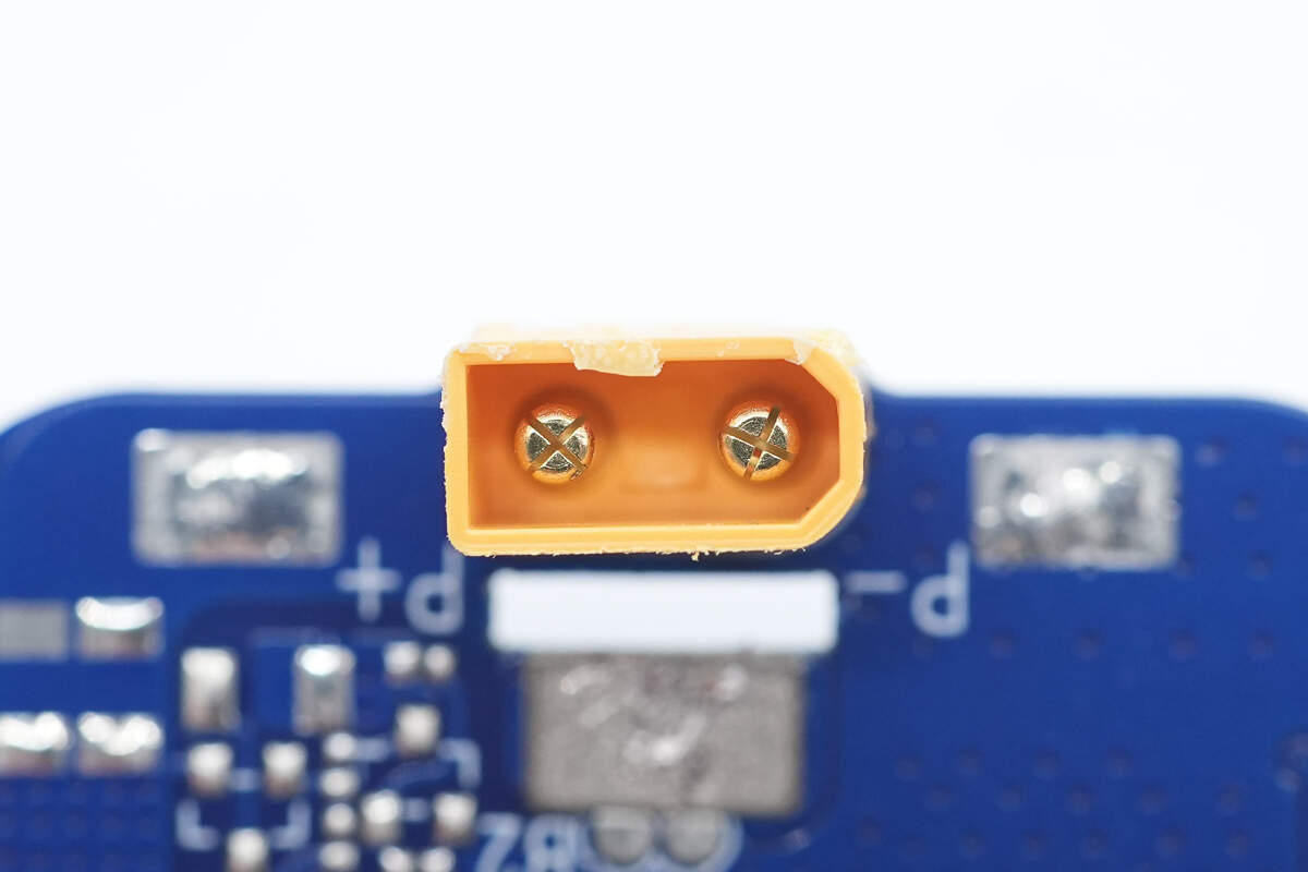
Close-up of the XT30 connector.
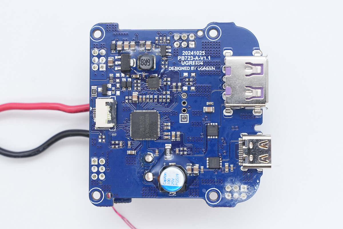
The front of the PCBA module features a synchronous buck-boost chip, a filter capacitor, and VBUS MOSFETs.
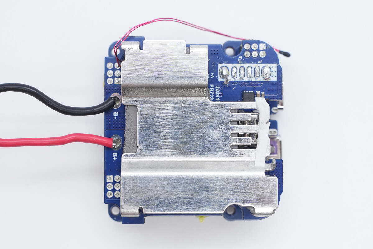
The back has a heatsink.
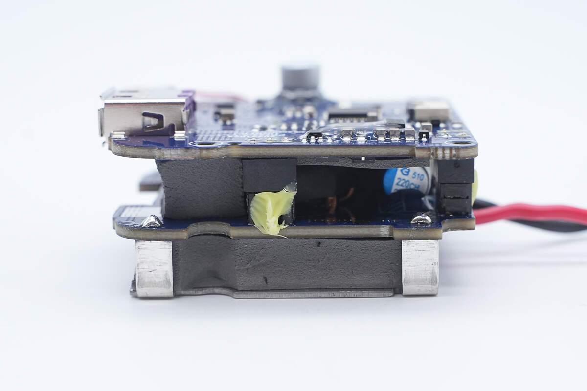
The PCBA module consists of two PCBs, with thermal pads sandwiched between the layers.
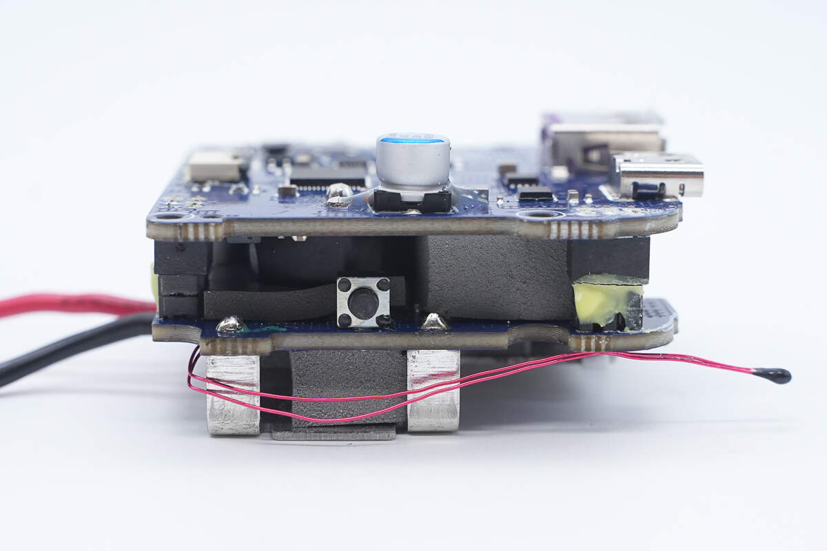
The other side features the power button.
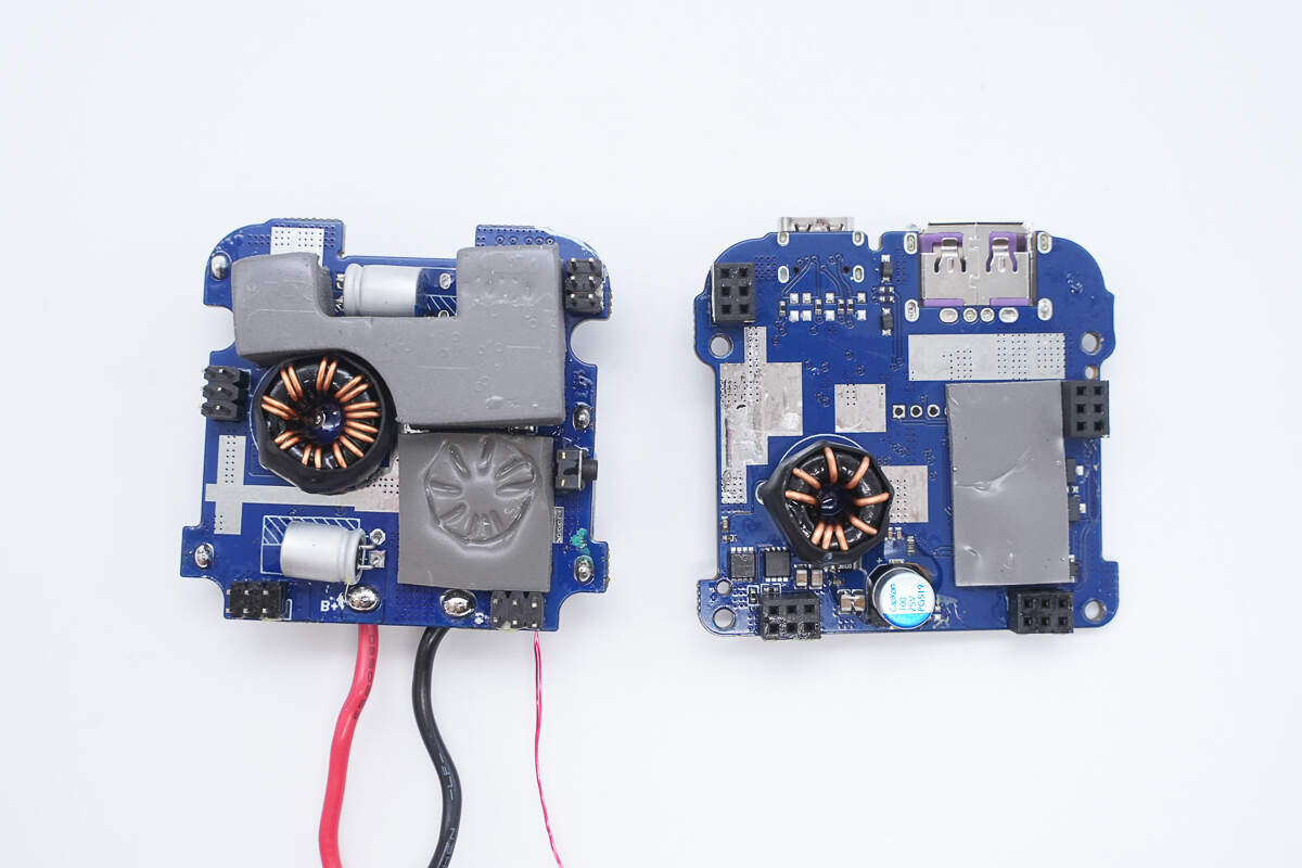
Separate the two PCBs.
The PCB with the soldered built-in cable also has the battery pack connections and thermistor soldered to it.
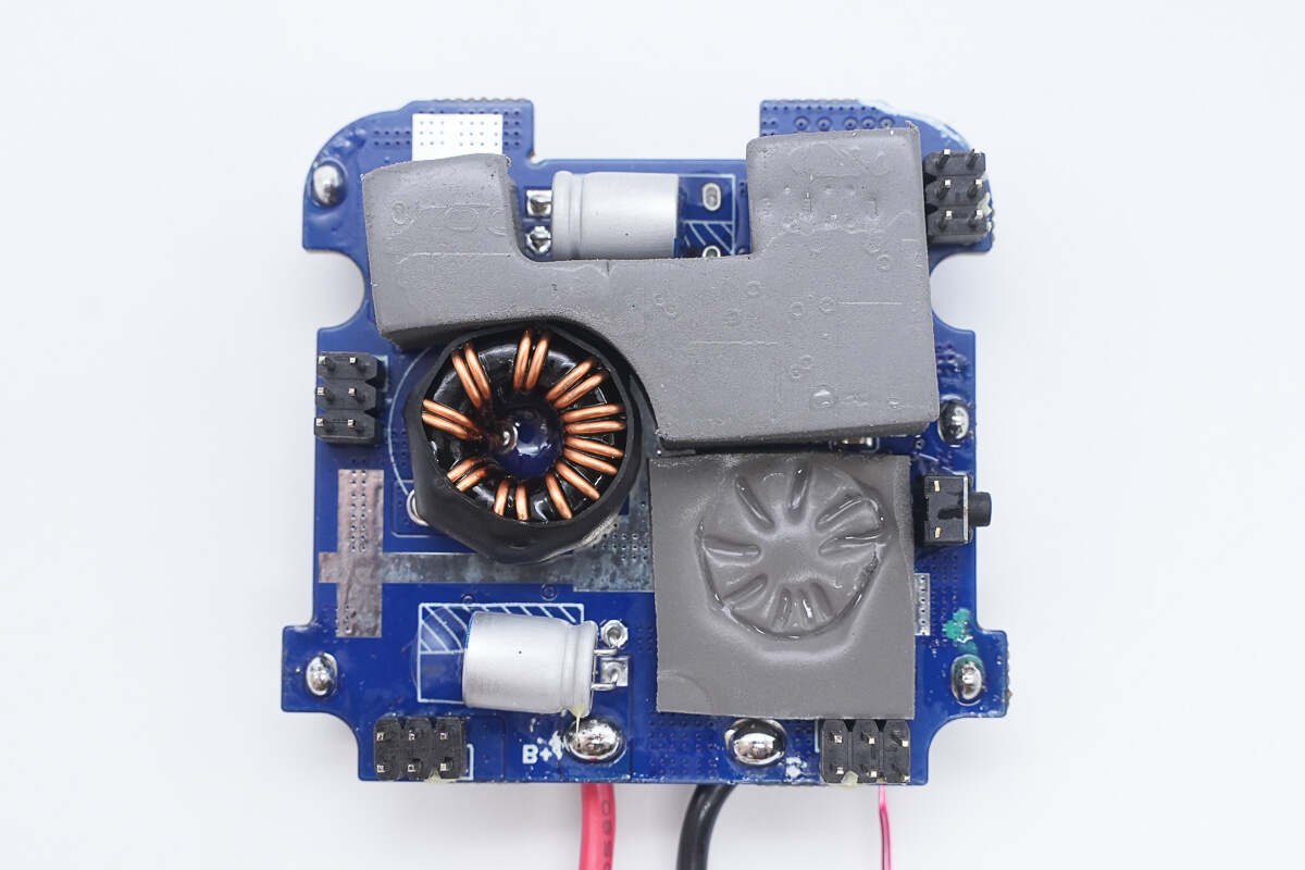
The other side has a toroidal inductor, thermal pads, and two solid-state capacitors.
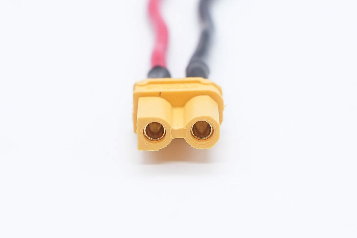
Close-up of the XT30 connector for the battery connection.
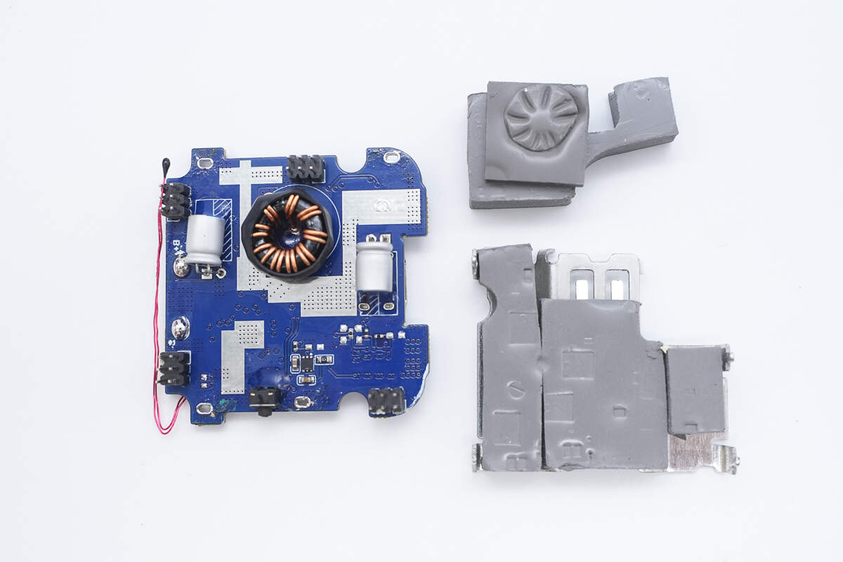
Remove the covered heatsink and thermal pads.
The PCB features a master control chip, synchronous buck-boost MOSFETs, and VBUS MOSFETs.
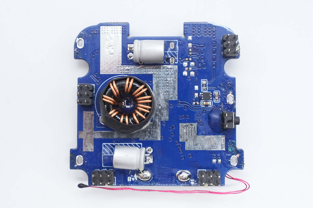
The other side has a toroidal inductor, solid capacitors, and pin headers.
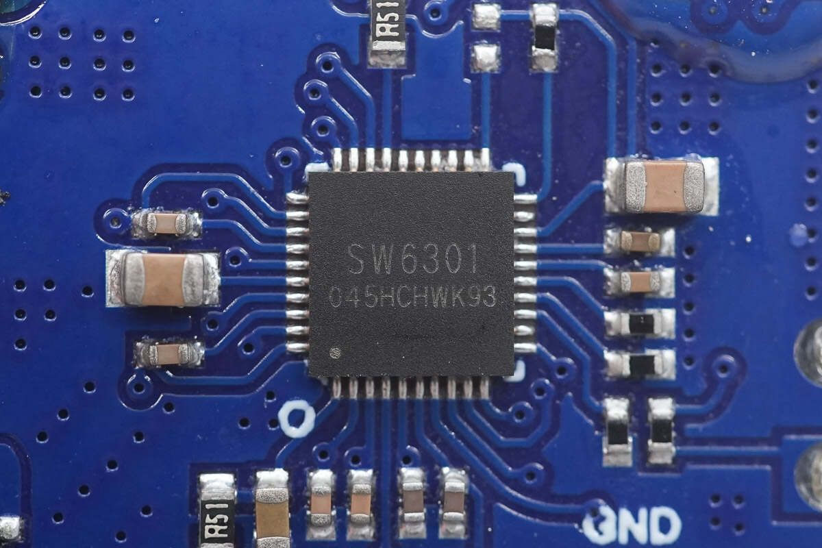
The master control chip is from iSmartWare, model SW6301. It is a high-performance synchronous buck-boost power bank SOC that supports fast charging through a single USB-C port. It operates over a 4 V to 26 V input voltage range and supports 2–6 series battery configurations, providing up to 100 W input and output. The chip supports a wide range of fast-charging protocols, including PD, SCP, FCP, AFC, QC, and SFCP, ensuring excellent compatibility and charging efficiency.
Users can easily set target charging voltage and current via the I²C interface. It also supports 3–5 LED battery indicators, an 188-segment digital display, and customizable digital displays, allowing users to monitor device performance and status intuitively. The SW6301 comes in a QFN 5×5-40 package and is suitable for high-power power banks, outdoor power supplies, and power tools.
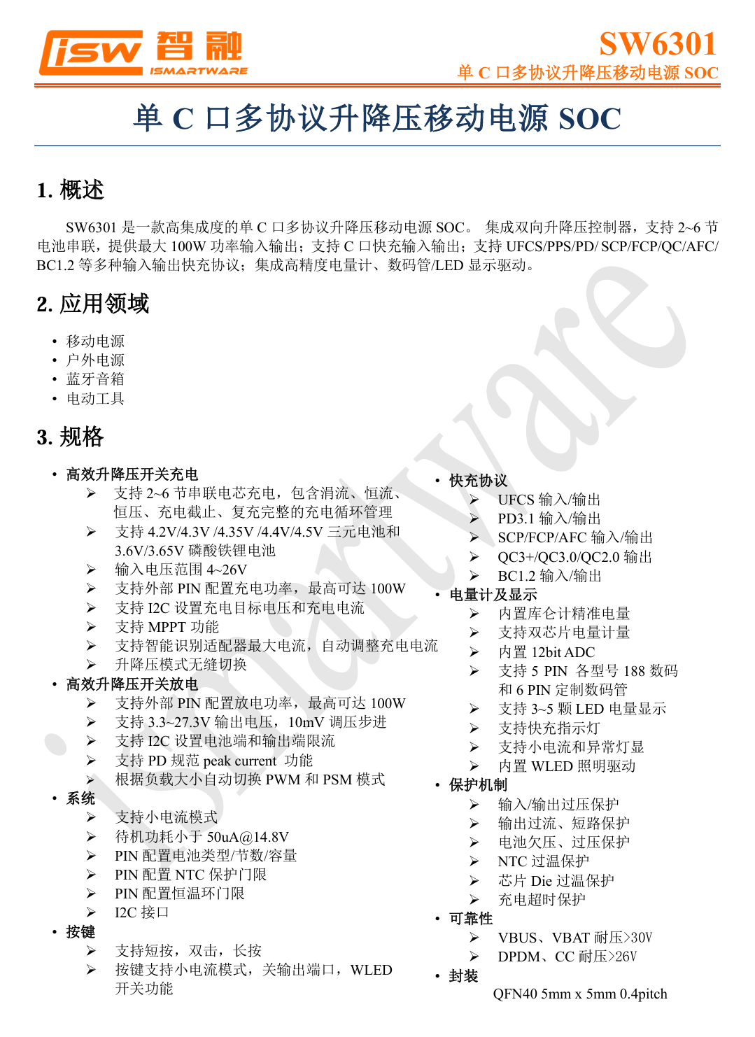
Here is the information about iSmartWare SW6301.
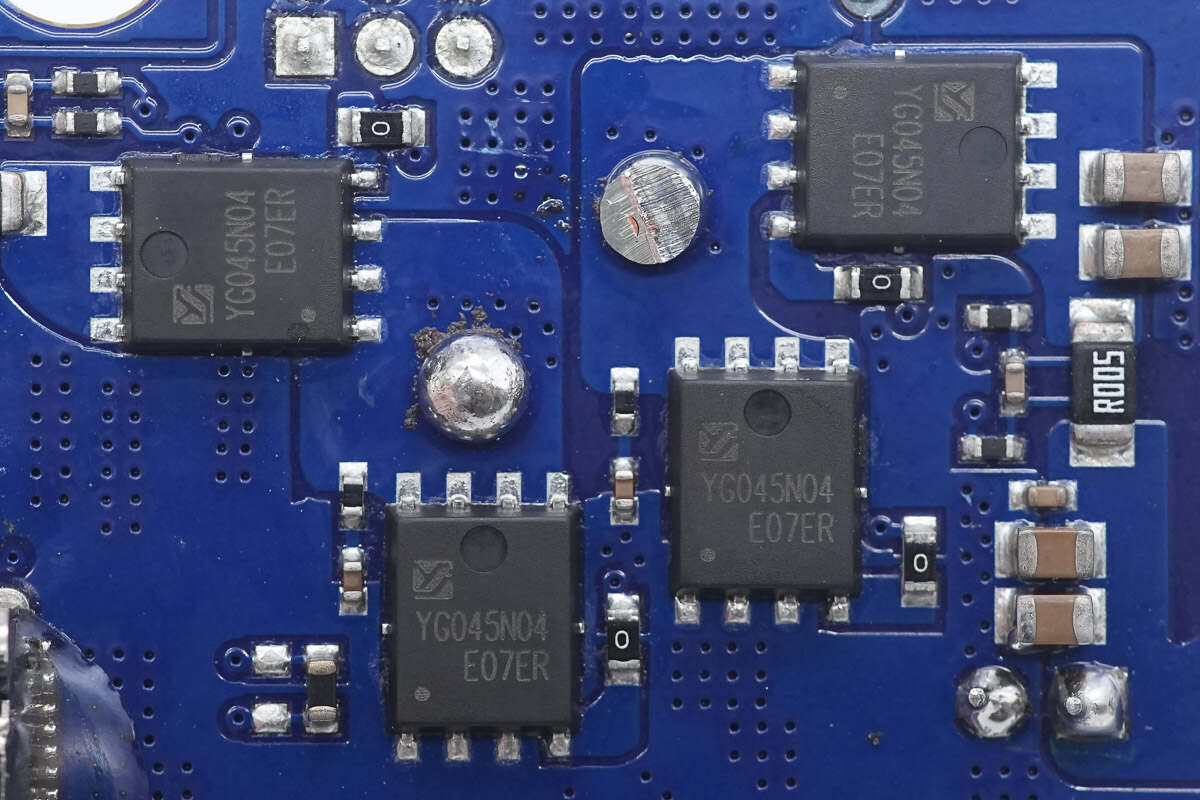
The synchronous buck-boost MOSFETs are model YG045N04ADQ, NMOS devices with a voltage rating of 40 V and an on-resistance of 4.5 mΩ, packaged in PDFN 5×6.
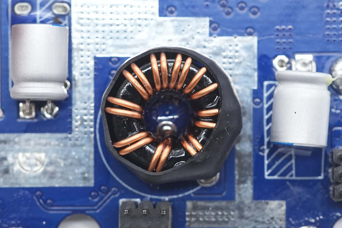
The buck-boost inductor is wound as a toroid and insulated with a heat-shrink sleeve.
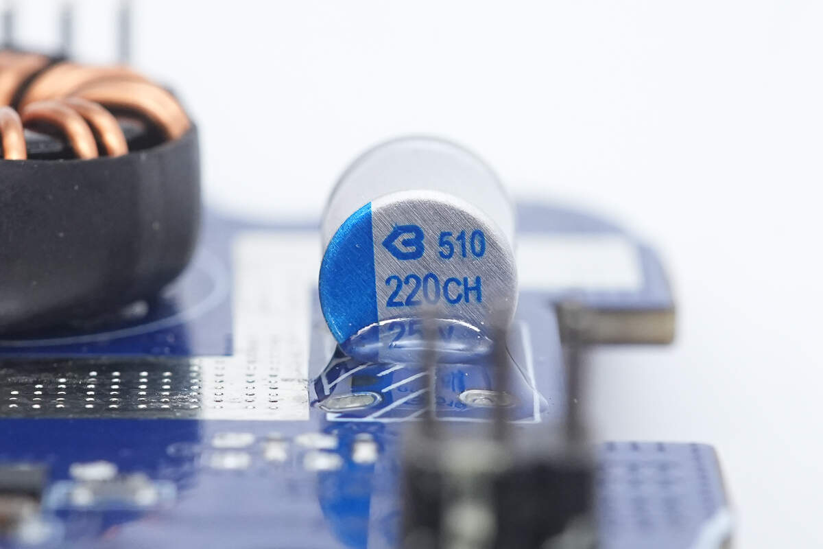
The filter capacitors are from BERYL, CH series solid-state capacitors, rated at 220 μF, 25 V.
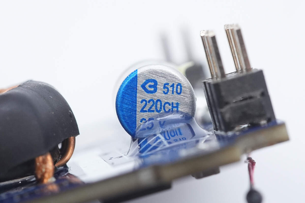
The other capacitor has the same specifications.
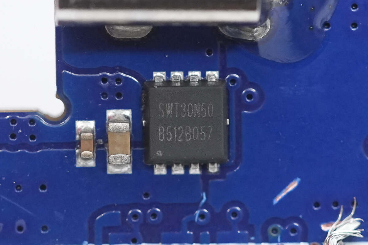
The VBUS MOSFET is from iSmartWare, model SWT30N50, in a PDFN 3×3 package.
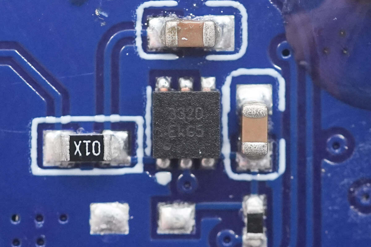
The E-Marker chip is marked with 332D, model HUSB332D. It is a USB Type-C eMarker chip launched by Hynetek. The chip supports USB Type-C Specification 2.2, USB Power Delivery Specification 3.1, USB4 2.0, as well as Thunderbolt 3 and 4 standards, and is compatible with the USB PD3.1 EPR.
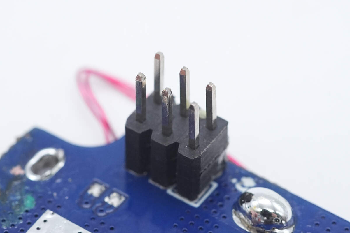
Close-up of the pin headers connecting the two PCBs.
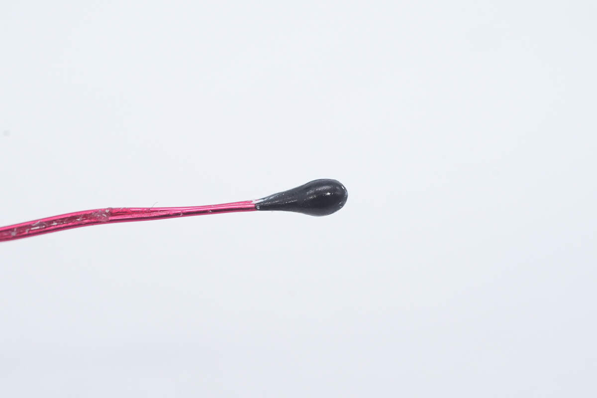
The NTC thermistor is used to monitor the battery temperature.
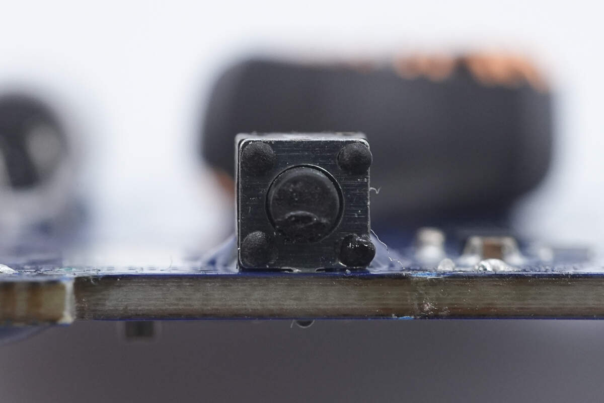
The power button is soldered using through-hole mounting.
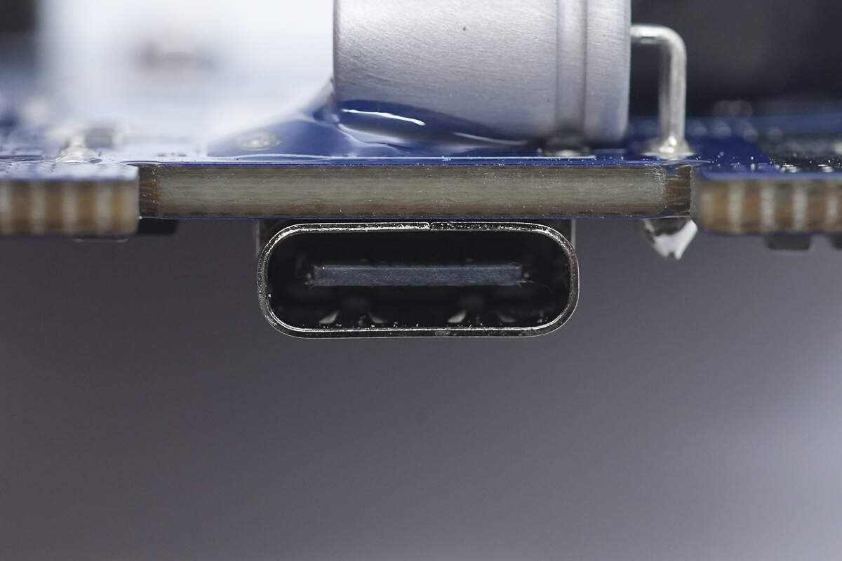
Close-up of the USB-C female port securing the built-in cable.
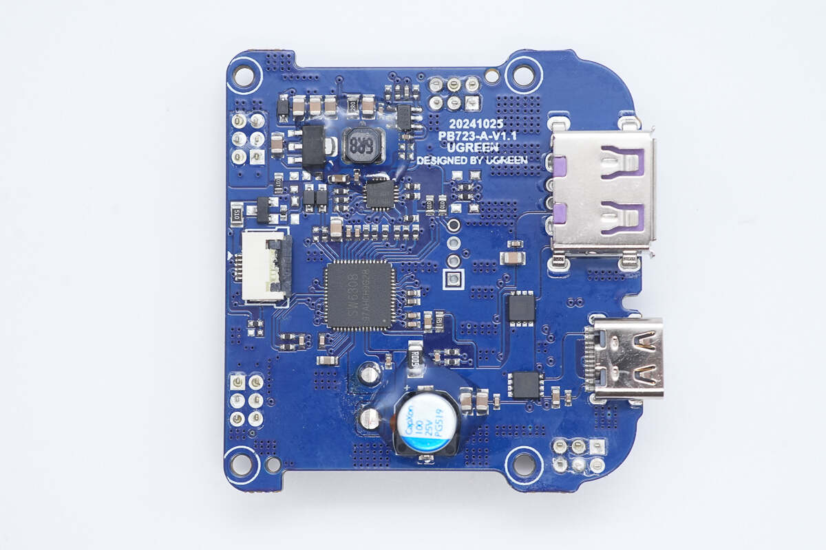
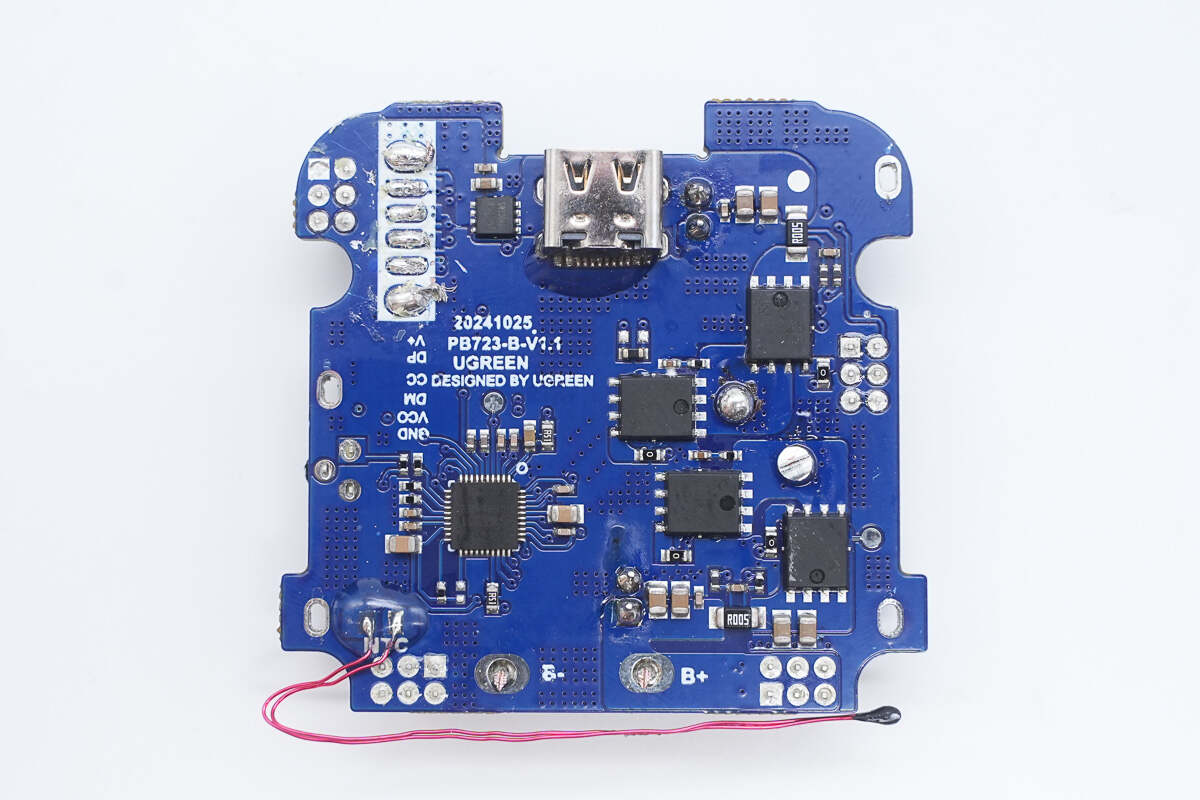
The front of the PCB features a master control chip, buck chip, MCU, filter capacitors, VBUS MOSFETs, and USB-C and USB-A ports.
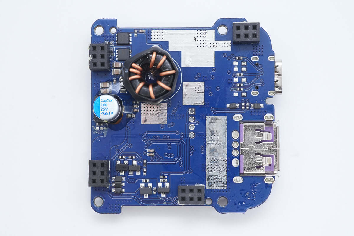
The back has synchronous buck-boost MOSFETs, a toroidal inductor, and a filter capacitor.
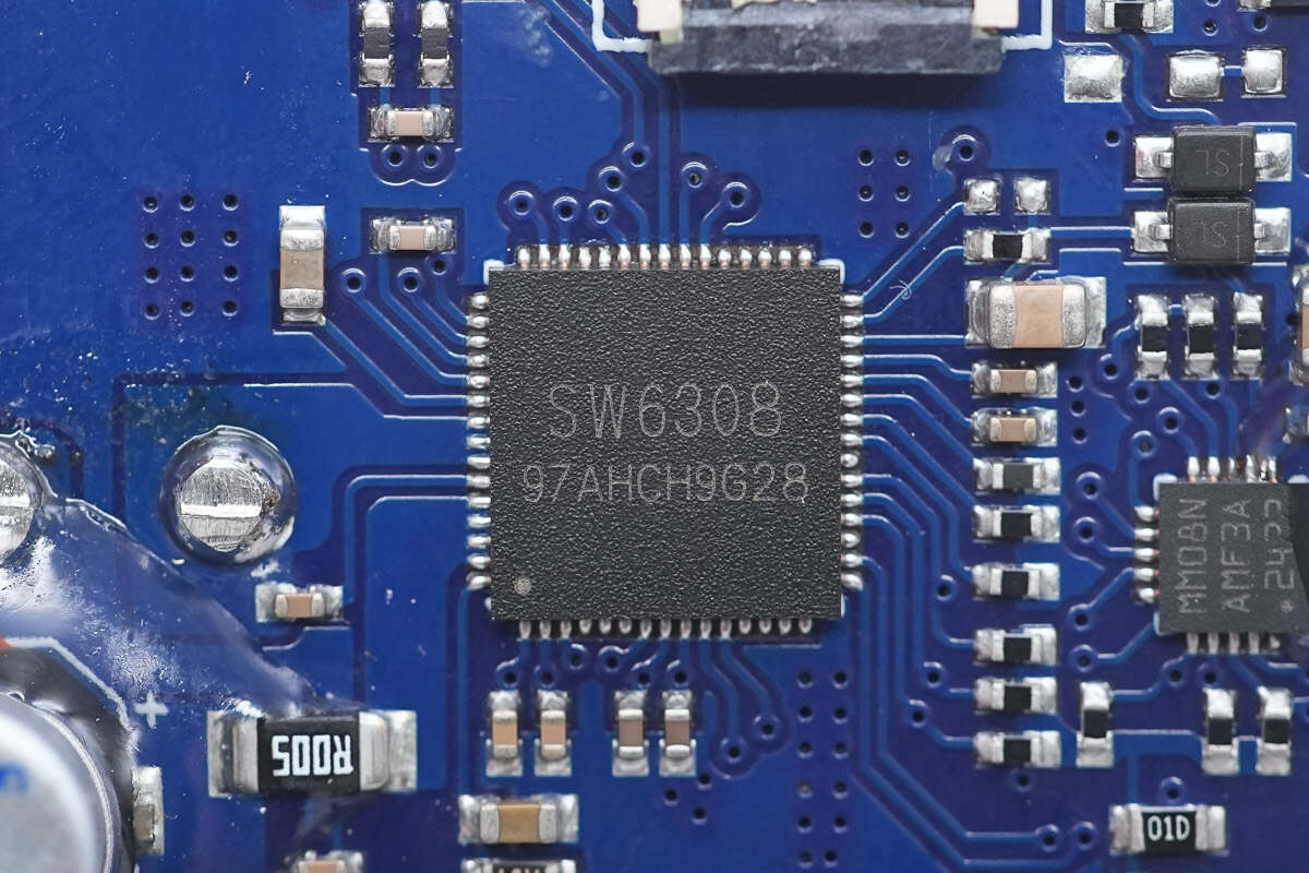
The master control chip is from iSmartWare, model SW6308. It is a high-performance synchronous buck-boost power bank SOC supporting USB-C, USB-A, and Lightning interfaces. It operates over a 4 V to 26 V input voltage range and supports 2–6 series battery configurations, providing up to 45 W input and output, with dual USB-C ports capable of fast charging in any port.
The SW6308 supports a wide range of fast-charging protocols through UFCS, including PD, SCP, FCP, AFC, QC, and SFCP, ensuring excellent compatibility and charging efficiency. The chip integrates two internal MOSFETs, and with two external battery-side switches, it forms a bidirectional synchronous buck-boost topology, reducing external components for a more cost-effective design.
SW6308 features extremely low standby current (50 μA) and comprehensive protection functions, including input/output overvoltage protection, input overcurrent and short-circuit protection, battery undervoltage and overvoltage protection, external NTC-based overheat protection, internal overtemperature protection, and a charging safety timer. It supports 3–5 LED battery indicators and an 188-segment digital display. The chip comes in a QFN 7×7-60 package with minimal external components.
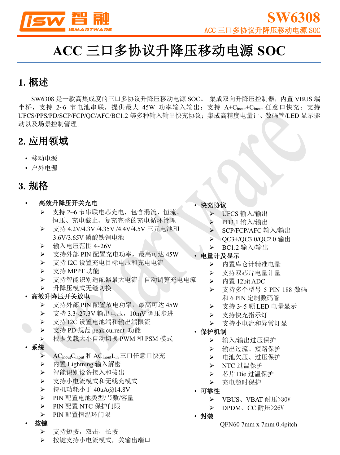
Here is the information about iSmartWare SW6308.
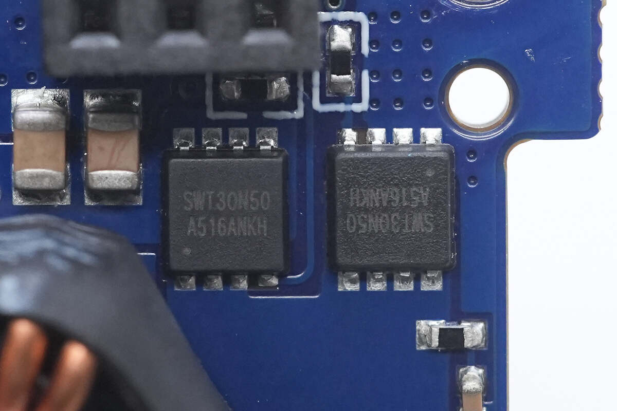
The battery-side half-bridge MOSFETs are iSmartWare SWT30N50.

The buck-boost inductor is toroidally wound and insulated with a heat-shrink sleeve.
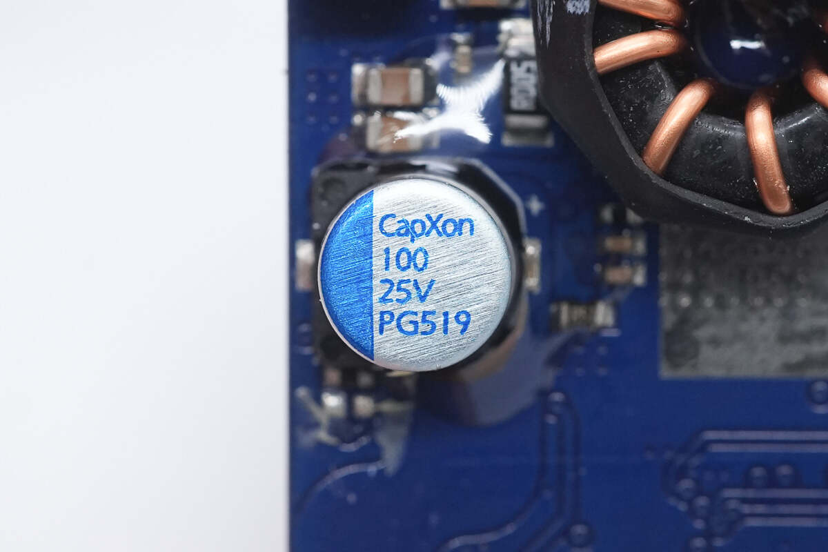
The filter capacitors are from CapXon, rated at 100 μF, 25 V.
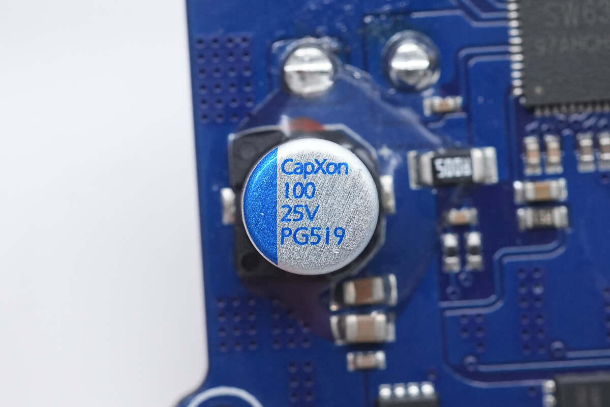
The other capacitor has the same specifications.
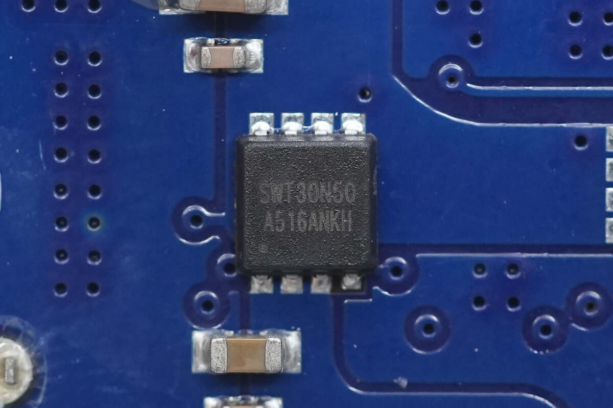
The USB-C port VBUS MOSFET is from iSmartWare, model SWT30N50, in a PDFN 3×3 package.
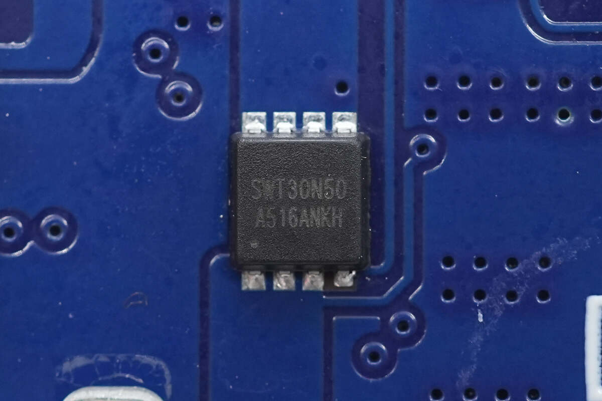
The USB-A port VBUS MOSFET has the same model.
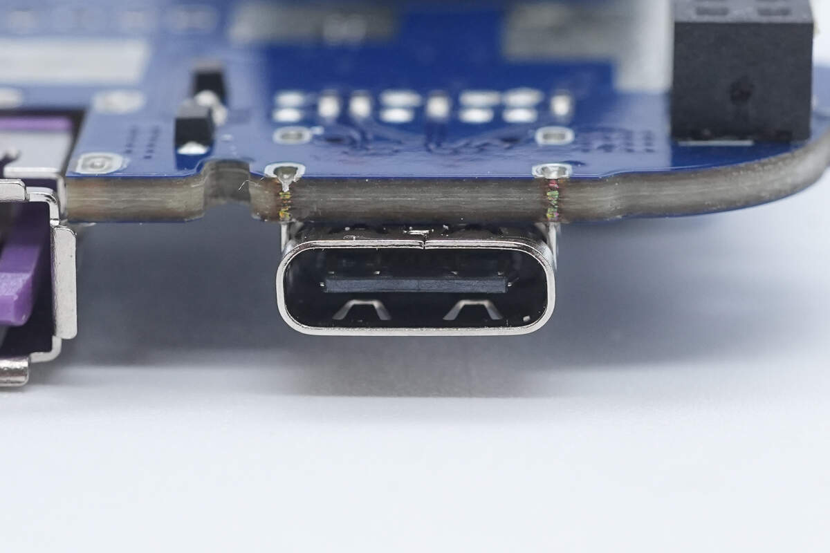
The USB-C socket is secured with through-hole soldering.
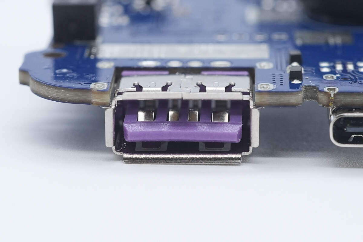
The USB-A socket is also secured with through-hole soldering.
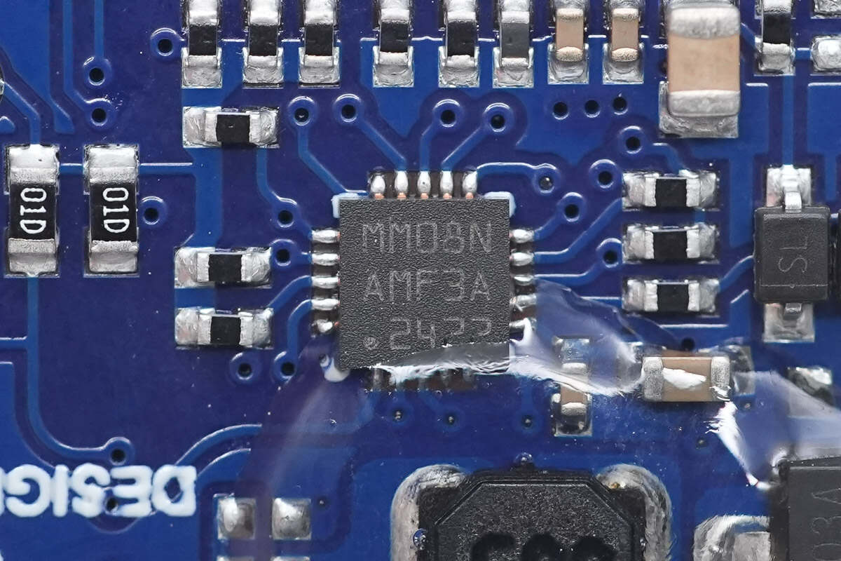
The MCU is from MindMotion, model MM32G0001N, featuring an integrated 32-bit Arm Cortex-M0 core, 16 KB of FLASH, and 2 KB of SRAM. It provides USART, I²C, and SPI interfaces and comes in a QFN20 package.
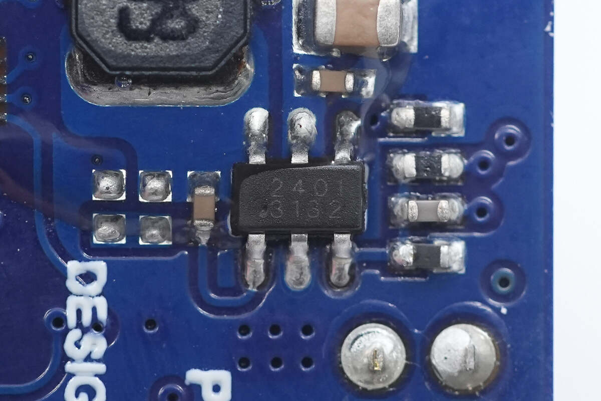
The buck chip is from SCT, model SCT2401. It is a synchronous buck converter with an input voltage range of 4.5–40 V, an output current of 600 mA, a switching frequency of 1.2 MHz, and comes in a TSOT23-6 package.
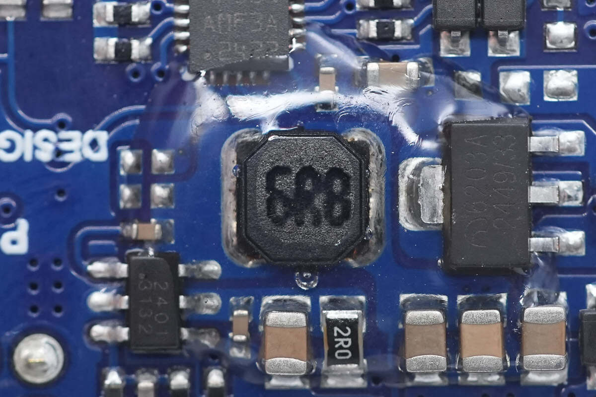
Close-up of the 6.8 μH buck inductor.
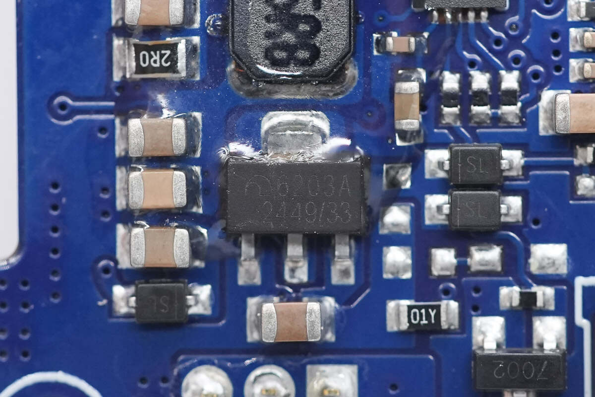
The voltage regulator supplying the MCU is from Microne, model ME6203A33PG. It supports a 7–30 V input, provides a 3.3 V output at 100 mA, and comes in a SOT-89 package.
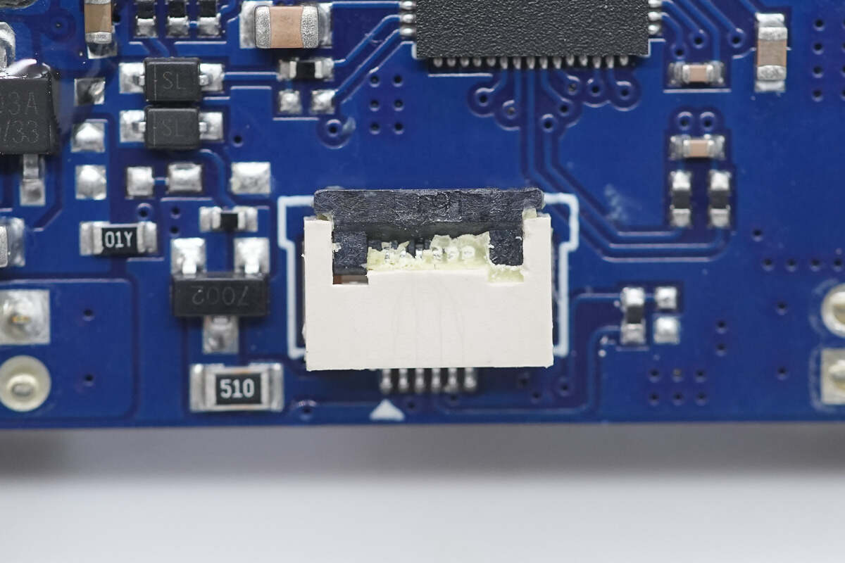
Close-up of the ribbon cable socket connecting the display.
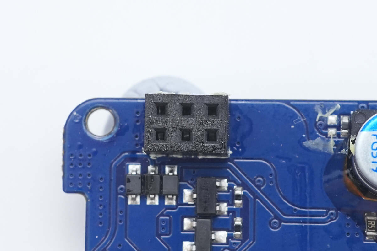
Close-up of the connector linking the two PCBs.

Well, those are all components of the UGREEN Nexode 20000mAh 130W Power Bank with Built-in USB-C Cable.
Summary of ChargerLAB
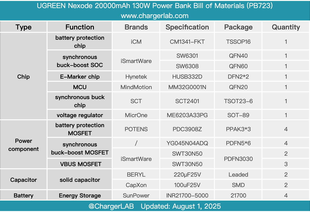
Here is the component list of the UGREEN Nexode 20000mAh 130W Power Bank with Built-in USB-C Cable for your convenience.
It continues the design language of the series and comes with a built-in USB-C cable. The built-in cable supports 100 W output and 80 W input, while the USB-C and USB-A ports support 33 W fast charging, allowing simultaneous charging of phones and laptops. The front features a digital display that accurately shows the remaining battery level.
After taking it apart, we found that it consists of a two-layer PCB module, making full use of the available space. Four SunPower INR21700-5000 cells are connected in series and secured with an insulating frame. The battery pack and PCBA module are designed separately and connected via connectors. The battery protection PCB uses an ICM CM1341-FKT protection chip and includes a balancing circuit.
The built-in cable supports 100 W output powered by the iSmartWare SW6301, while the USB-C and USB-A ports support 33 W output via the iSmartWare SW6308. A MindMotion MCU handles overall device control and the display functions. The PCBA module is equipped with thermal pads and heatsinks to enhance heat dissipation. The build quality is solid, and the components are reliable, meeting the requirements for fast, high-power charging and discharging.
Related Articles:
1. Teardown of Supermicro 720W 1U Redundant Power Supply (PWS-721P-1R)
2. Teardown of UGREEN Nexode 20000mAh 165W Power Bank with Retractable USB-C Cable (PB726)
3. Teardown of Walmart Onn. 72W Multi-Port GaN Wall Charger (WIAWHT36008513)