Introduction
The RedMagic 11 Pro+ supports 120W wired fast charging and 80W wireless fast charging. To match the upgraded wireless charging capability, RedMagic designed a dedicated 80W air-cooled wireless charging dock. It not only meets the handset’s high-power wireless charging requirements but also integrates a 5,000 RPM high-speed fan that automatically adjusts its speed according to the charging power to improve the overall wireless charging experience. The dock comes with a 120W fast-charging kit, which can power the 80W air-cooled wireless charging dock and also charge the phone directly. Let’s take a closer look at the design of this high-power wireless charging accessory.
Product Appearance
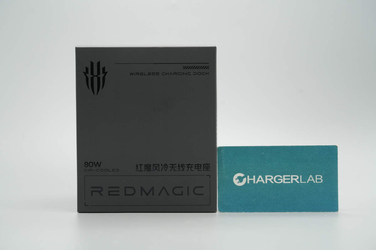
The front of the packaging features a stamped RedMagic logo along with the product name.
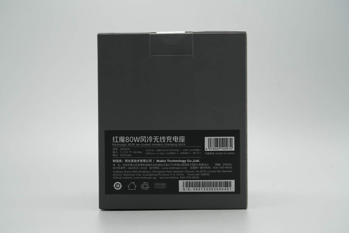
The back of the box carries the product information label.
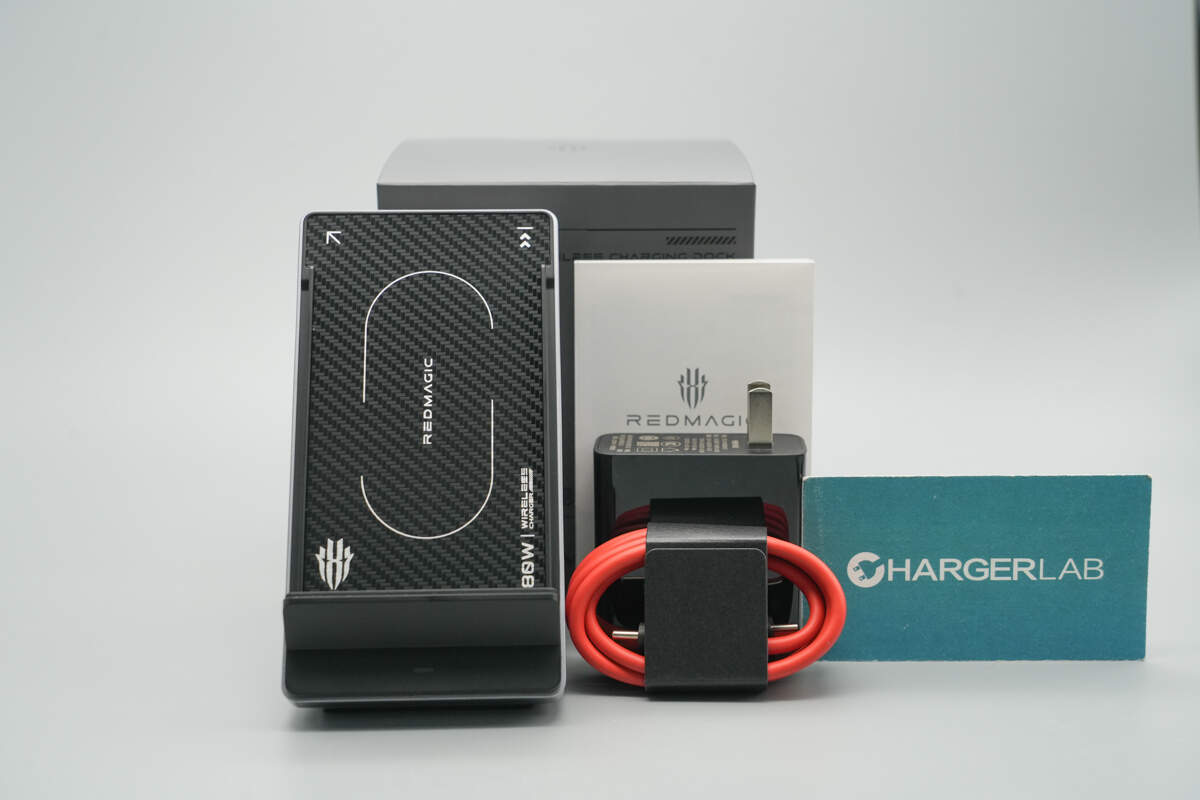
The package includes the RedMagic 80W air-cooled wireless charging dock, a 120W charging kit, and the user manual.
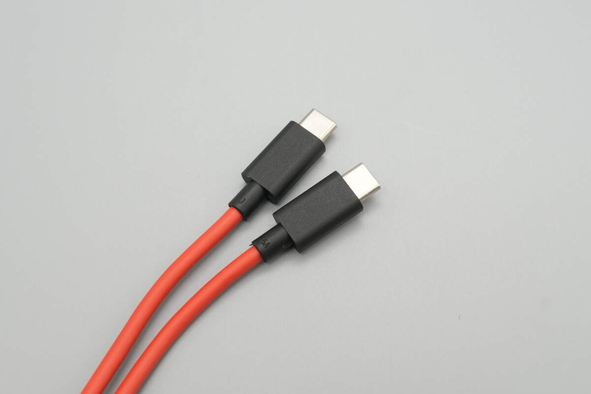
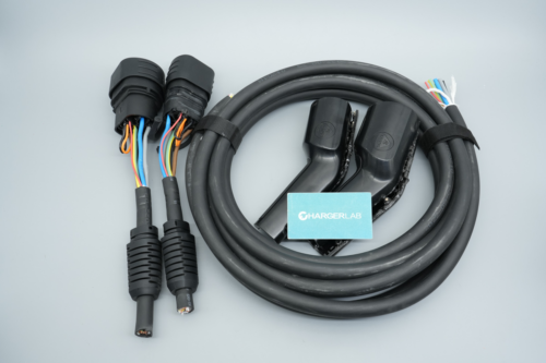
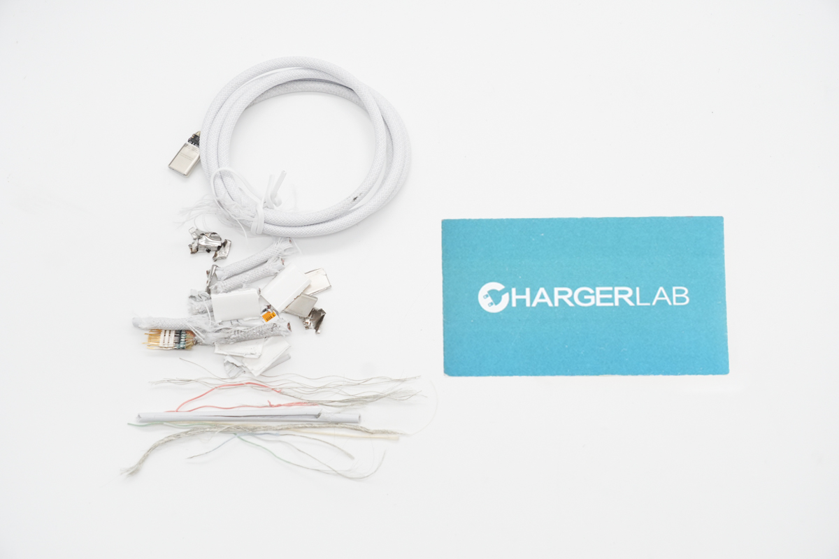
The included cable is a 6 A dual USB-C cable with a silicone-coated exterior.

The length of the cable is about 1 meter.
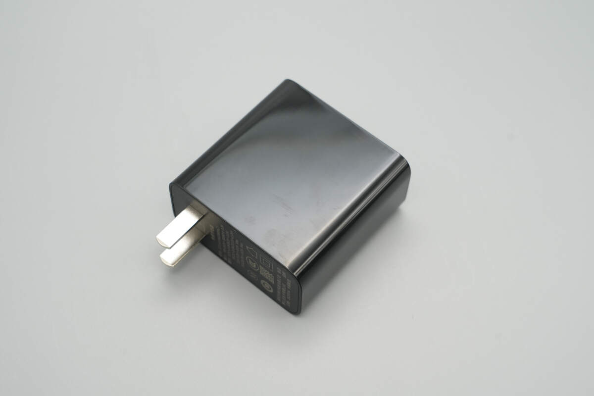
The charger’s single USB-C port supports 120W output, and the surface features a high-gloss finish.
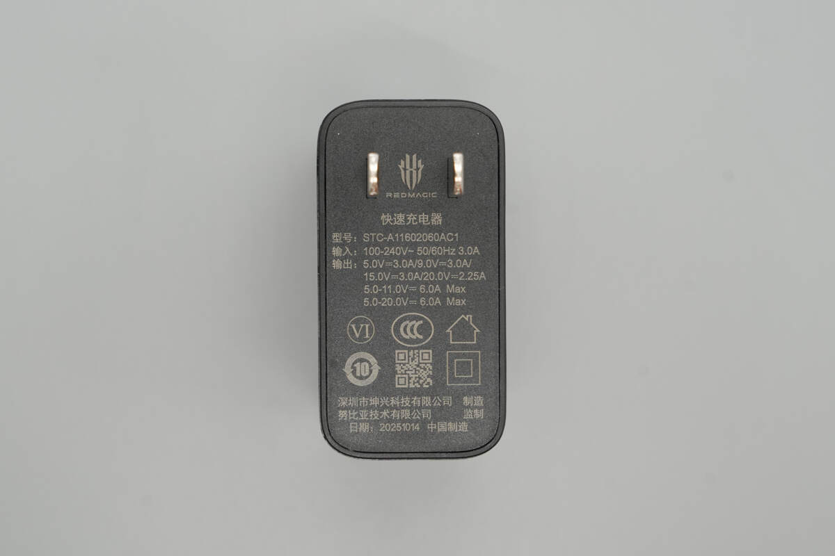
Model: STC-A11602060AC1
Input: 100–240 V~ 50/60 Hz, 3.0 A
Output: 5V⎓3A, 9V⎓3A, 15V⎓3A, 20V⎓2.25A, 5–11V⎓6A, 5–20V⎓6A Max
The charger is certified under the CCC standard and meets Level VI energy efficiency requirements.

ChargerLAB POWER-Z KM003C shows that the USB-C port supports QC3.0/4+, PD3.0, PPS, and DCP charging protocols.
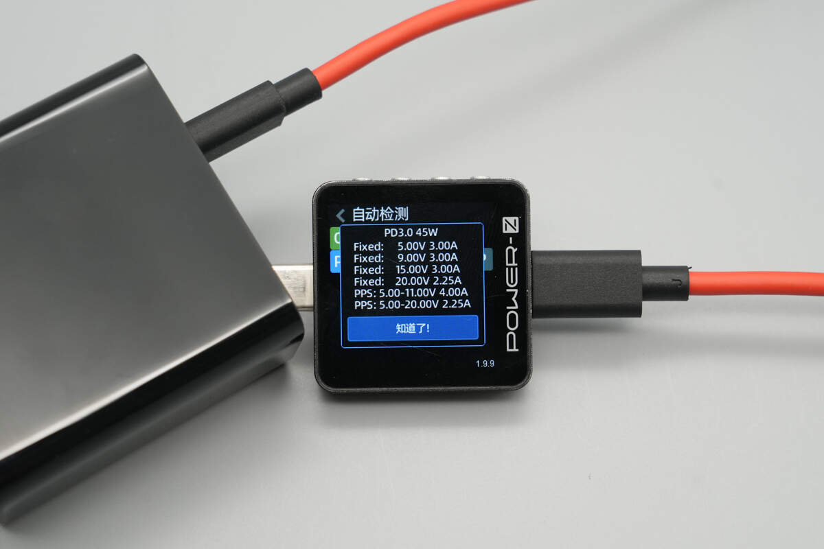
It features four fixed PDOs: 5V3A, 9V3A, 15V3A, and 20V2.25A, as well as two PPS voltage ranges of 5-11V4A and 5-20V2.25A.
The enclosure is made of flame-retardant PC material, giving it a high-tech appearance.
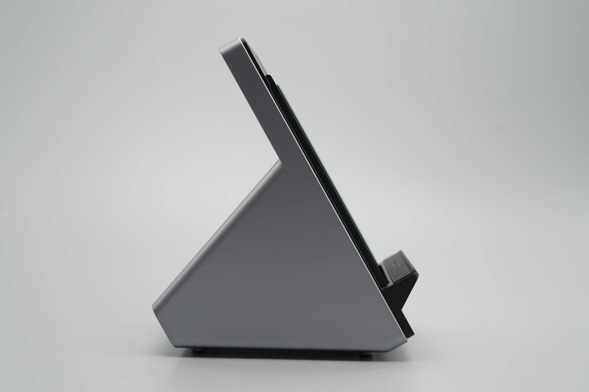
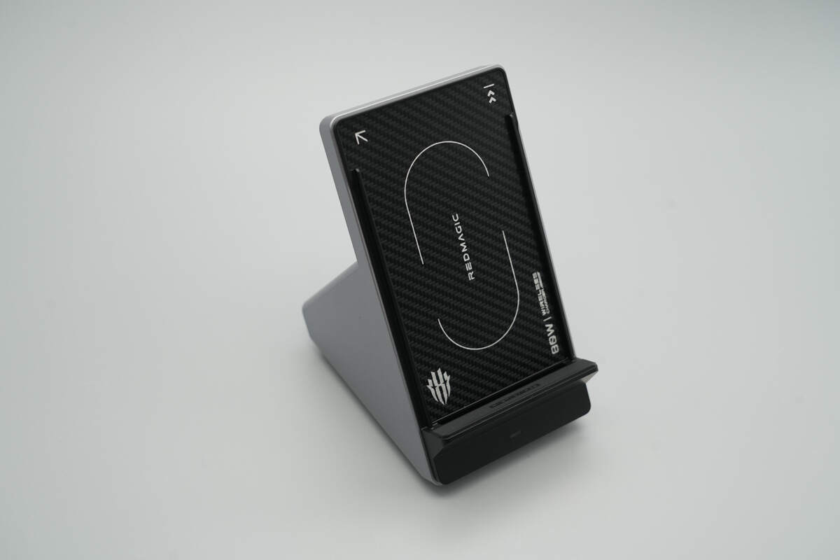
The charging panel is angled, serving both as a wireless charger and a phone stand.
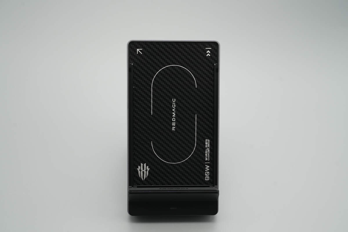
The front of the wireless charging panel features a carbon fiber texture, printed with the RedMagic logo and “80W WIRELESS CHARGER.”
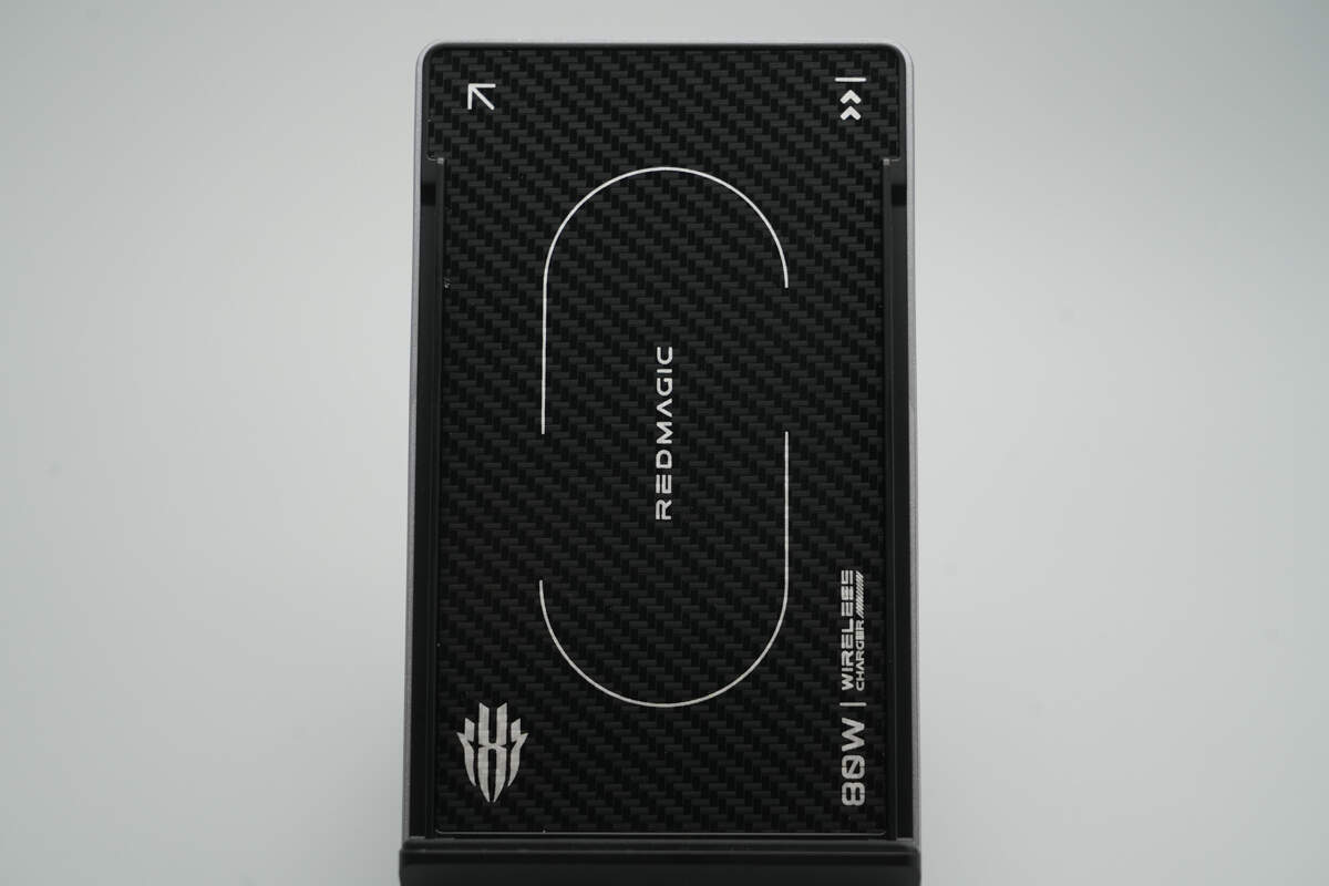
The panel contains dual coils, allowing the phone to charge in both horizontal and vertical orientations.
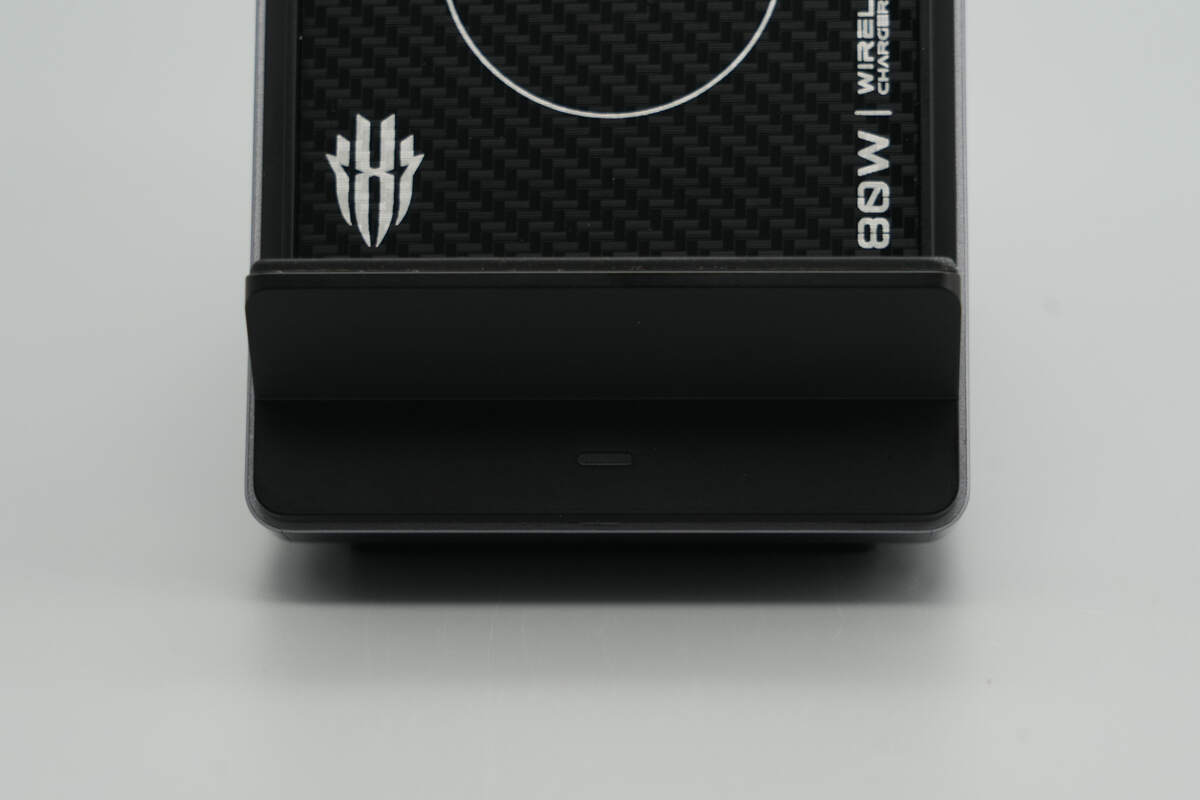
The bottom section houses the phone support platform and the LED indicator light.
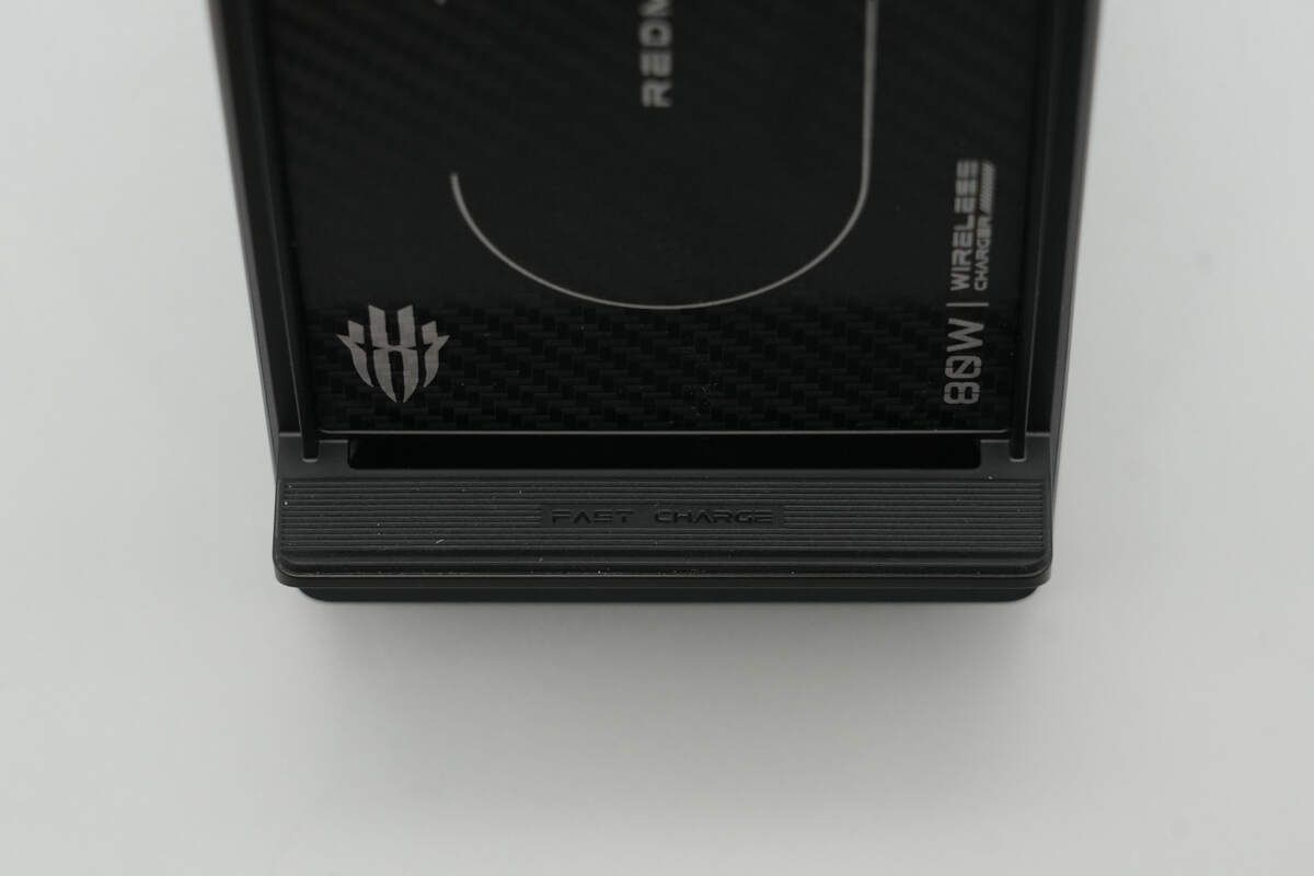
The support platform is equipped with a non-slip pad, with an air vent positioned nearby. Raised edges on both sides of the panel naturally create an airflow channel when the phone is placed on it, allowing the built-in fan to blow cool air and dissipate heat generated during wireless charging.
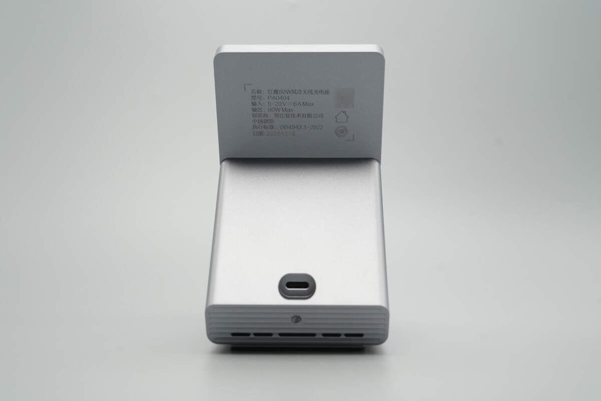
The back of the panel is printed with the product specifications.

Model: PA0404
Input: 5–20V6A Max
Output: 80W Max
The USB-C power input is located above the air intake vents.
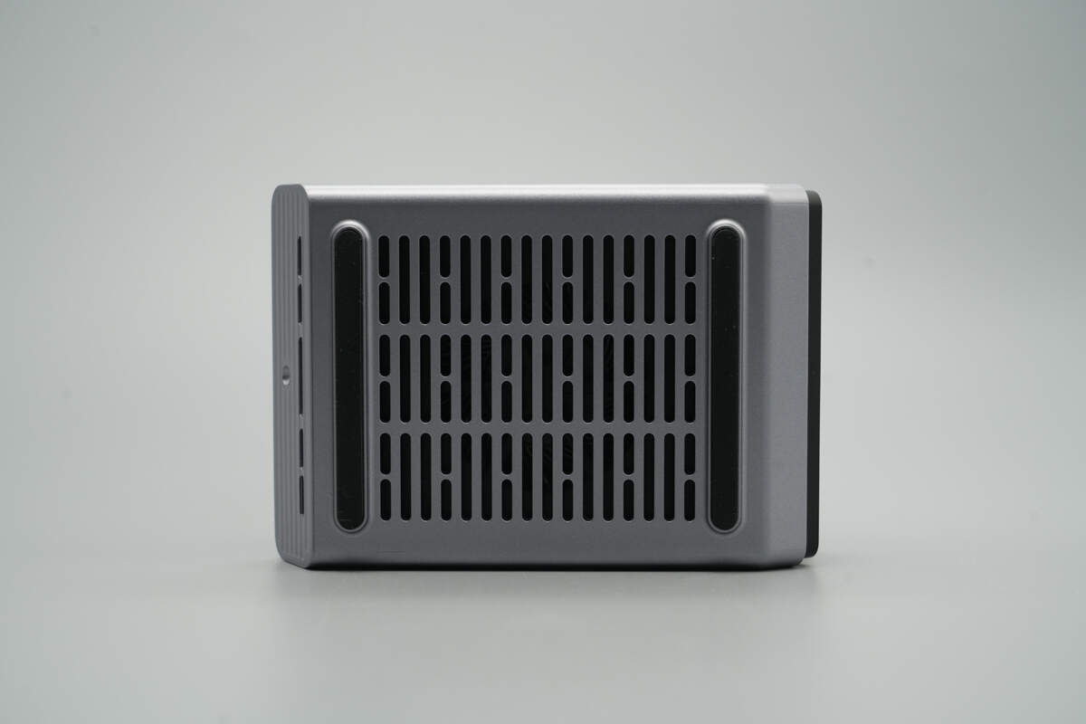
The bottom of the device also features air intake vents, with non-slip pads on both sides.

The length of the wireless charging panel is about 128.46 mm (5.057 inches).
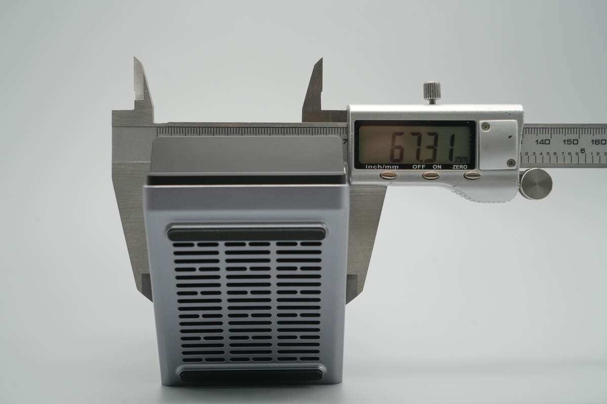
The width is about 67.31 mm (2.65 inches).
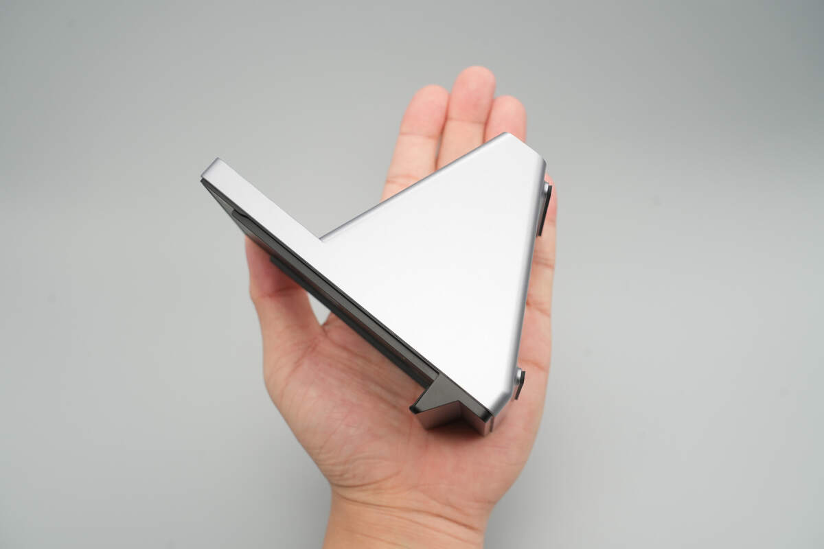
That's how big it is in the hand.
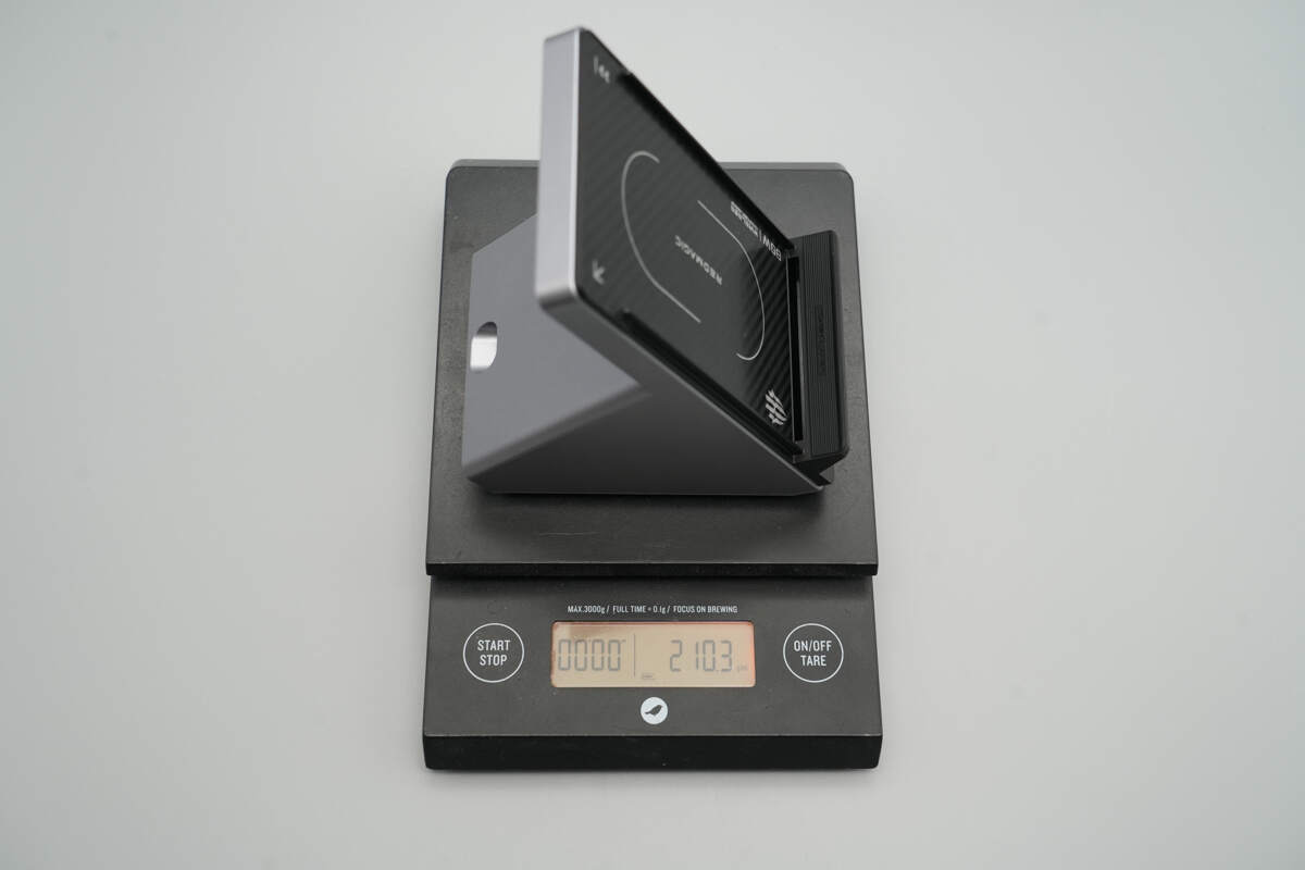
The weight is about 210 g (7.41 oz).
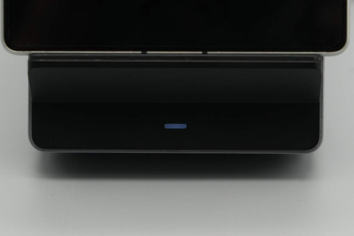
When powered on and charging wirelessly, the LED indicator remains steadily lit. It flashes during protection or error conditions.
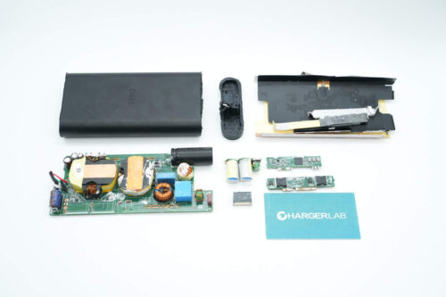
Teardown
Next, let's take it apart to see its internal components and structure.
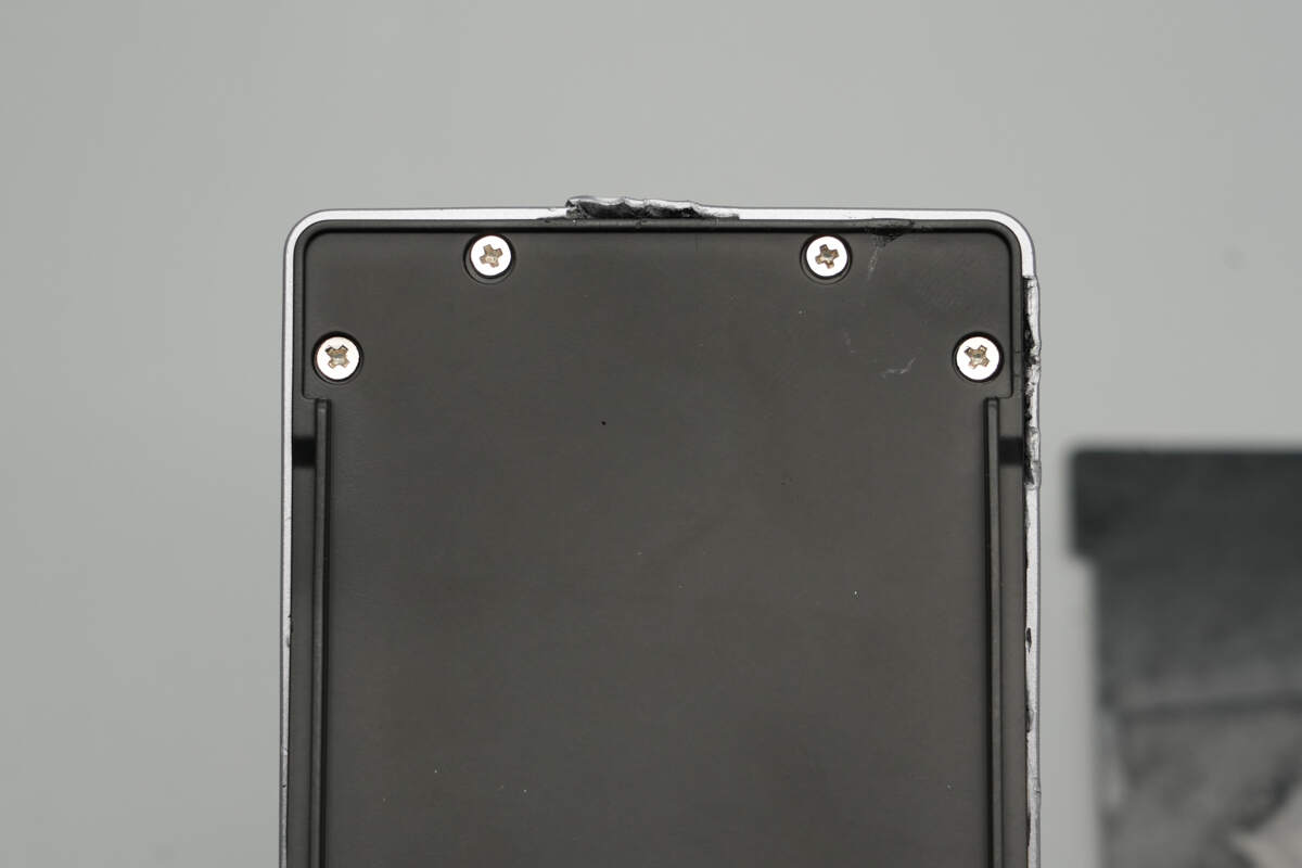
Removing the carbon fiber decorative panel reveals hidden screws inside.
Unscrew the hidden screws to open the wireless charging panel.
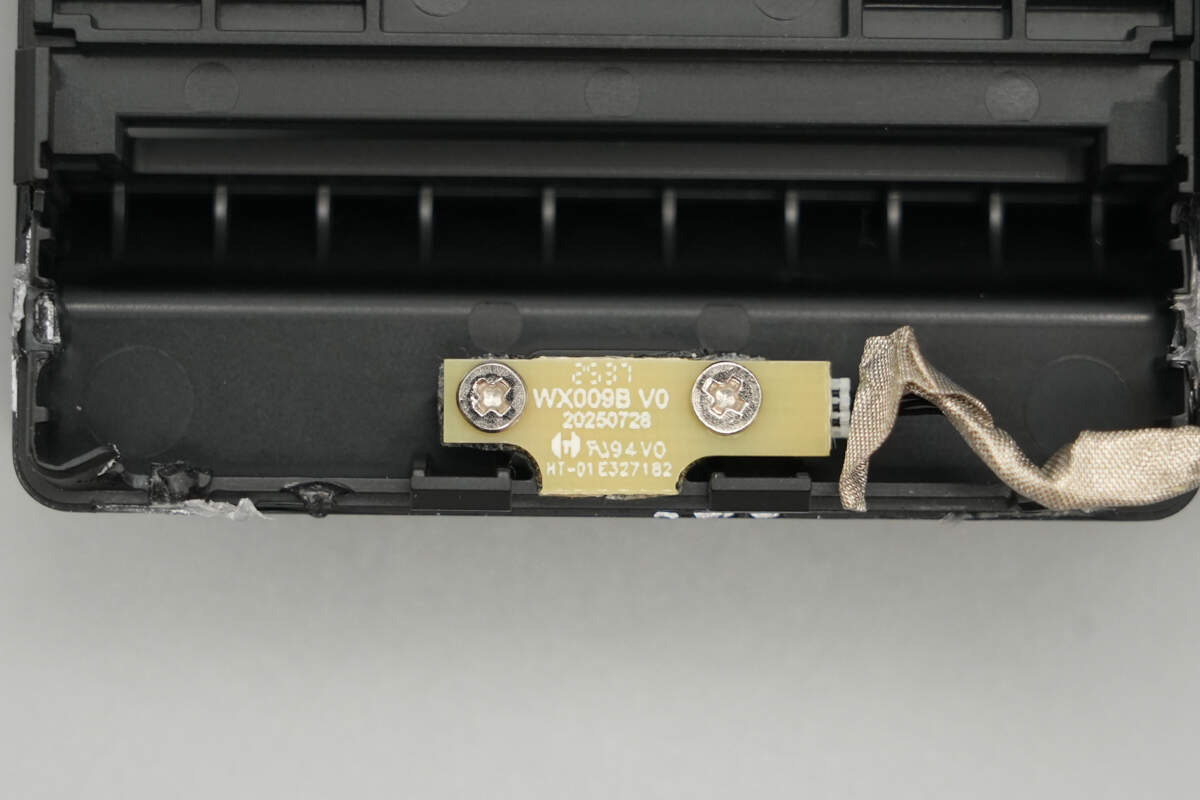
The PCB for the LED indicator is secured with screws, and its connecting wires use a plug-and-play design wrapped in conductive fabric.
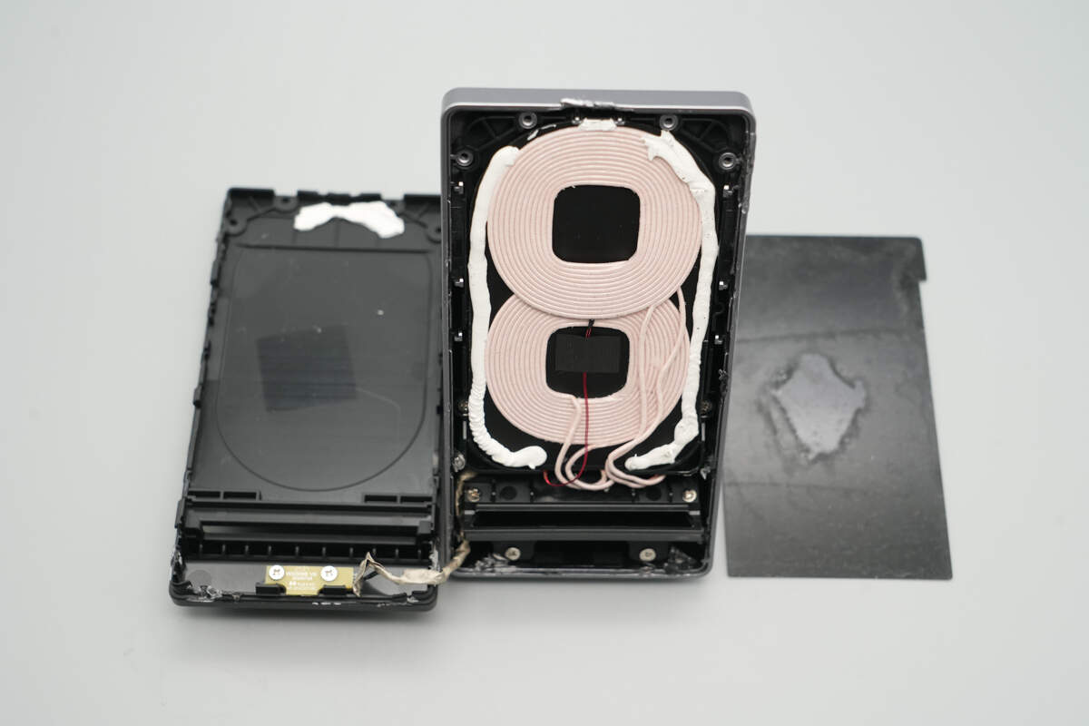
The wireless charging coils are secured to this support plate using double-sided adhesive.

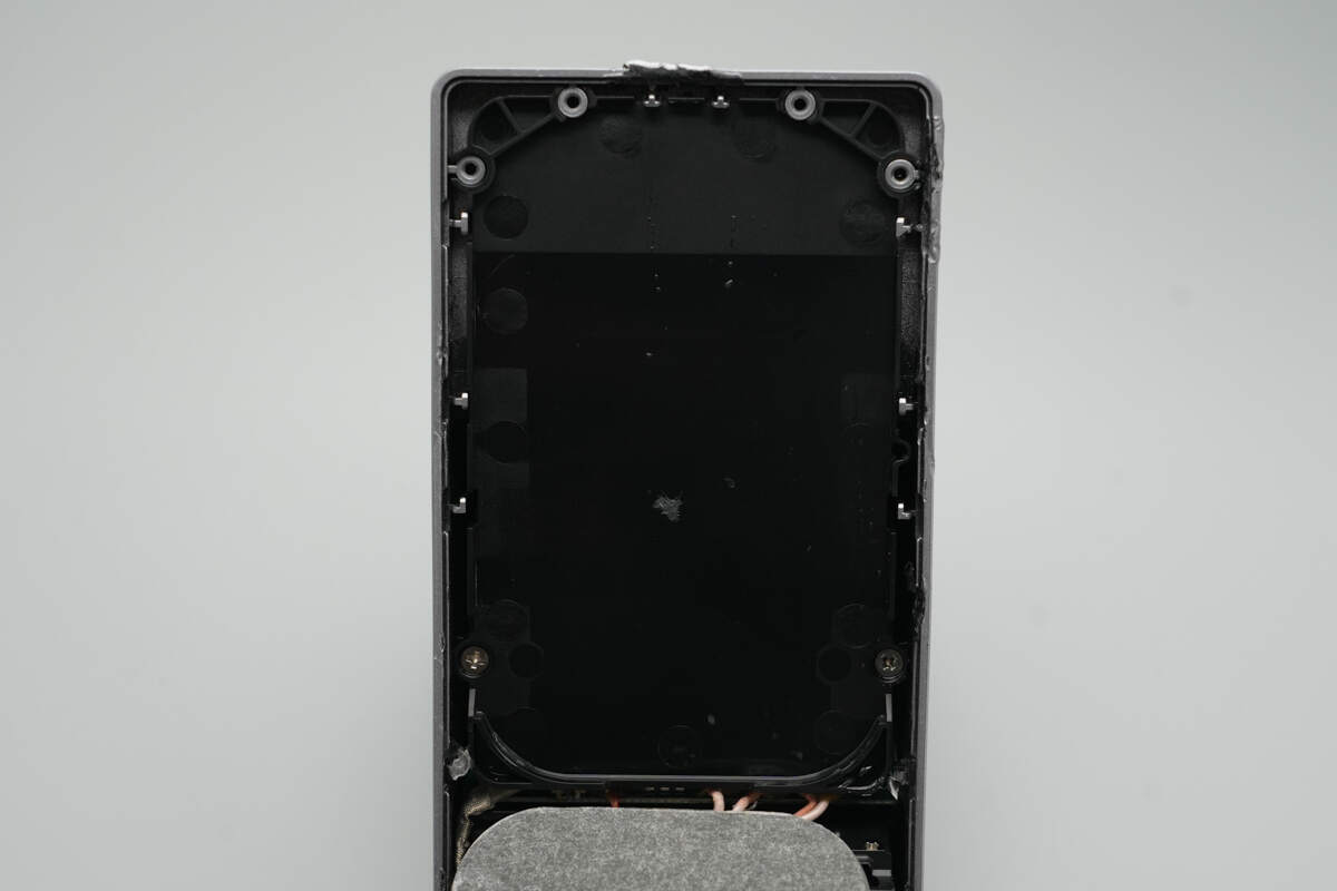
The support plate is secured in place with screws on both sides.
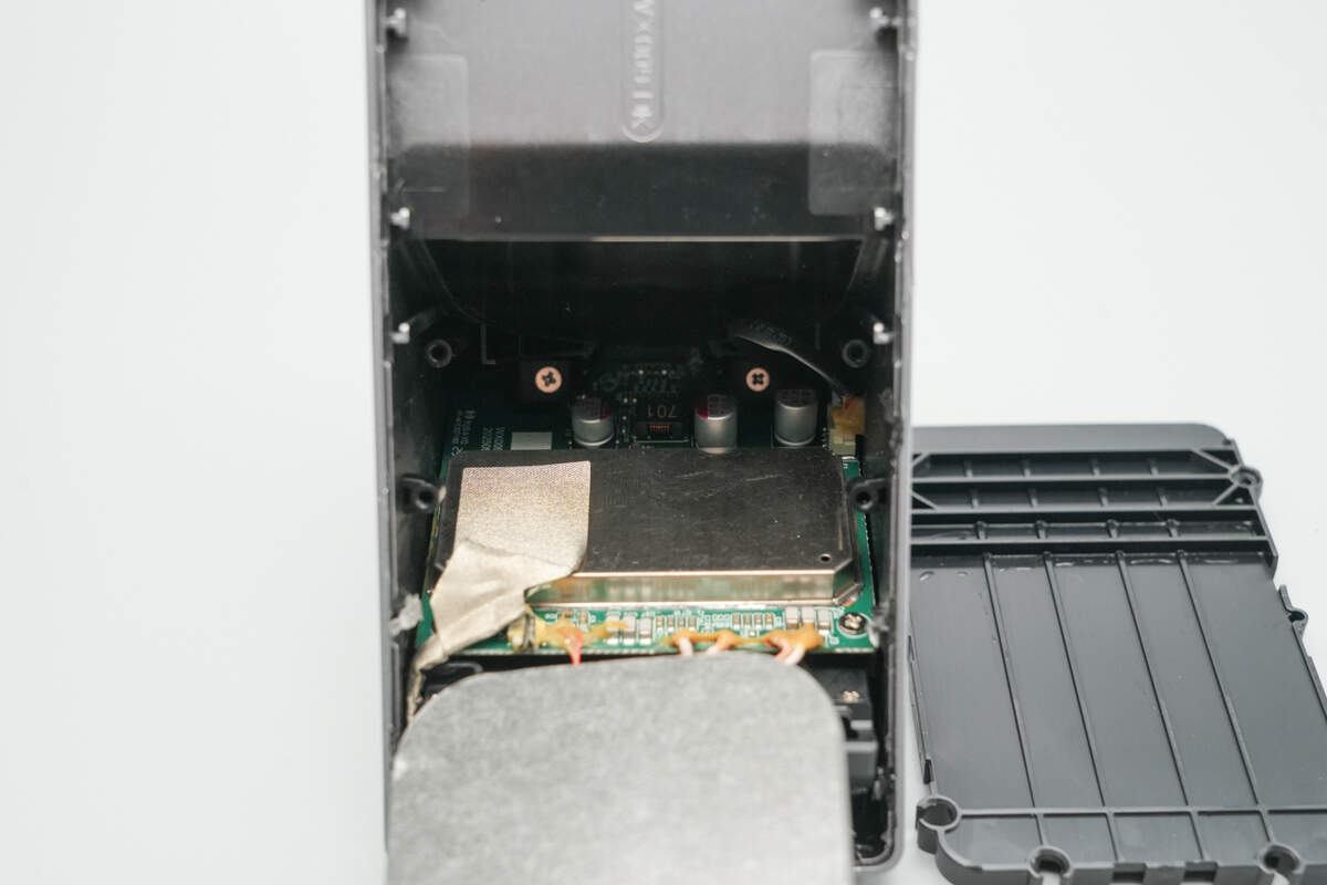
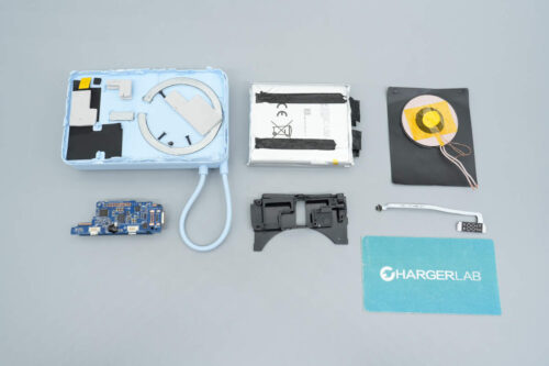
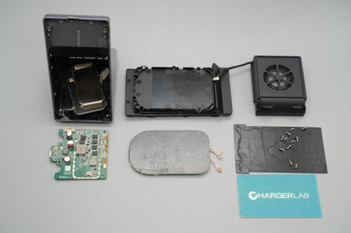
Remove the support plate. The PCBA and fan module are secured with screws.
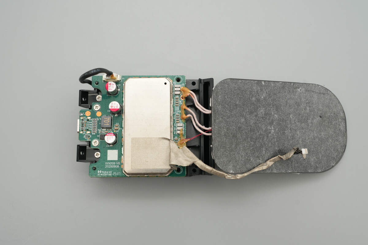
Remove the entire module. The PCBA is mounted on top of the fan with screws and connected via plug-and-play wires.

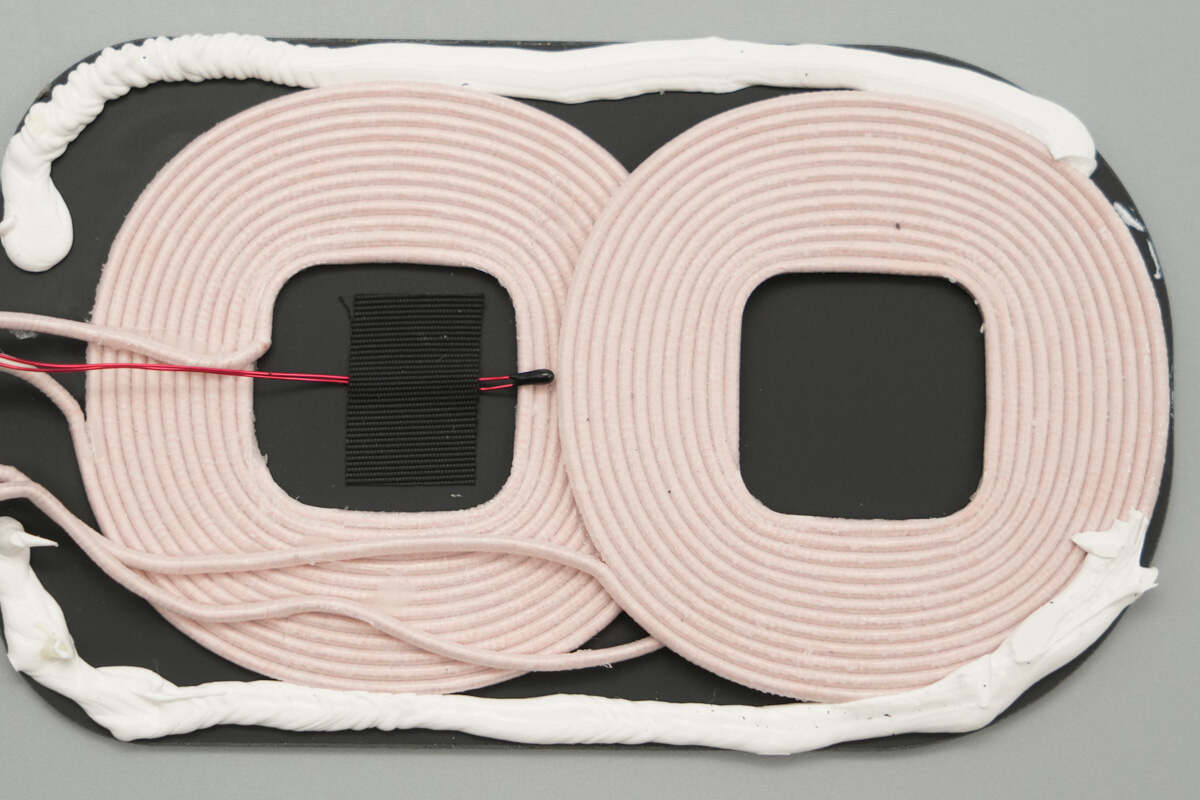
The soldering points between the wireless charging coils, thermistor, and PCB are sealed with adhesive, and one side of the shielding cover is lined with conductive fabric.

The two wireless charging coils are placed on a magnetic isolation sheet, with their edges sealed with adhesive and equipped with a thermistor.
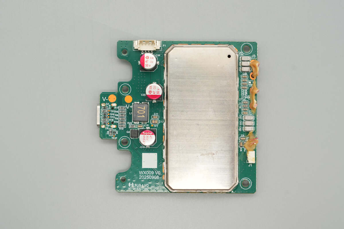
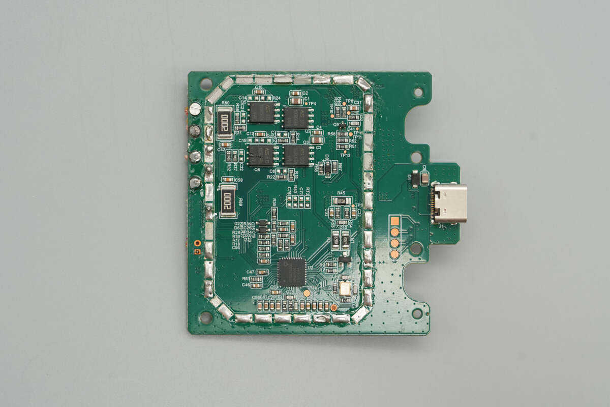
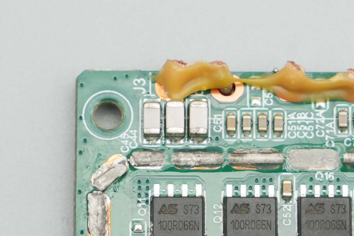
The front of the PCB is covered by a shielding cover. The exposed areas feature components such as a VBUS MOSFET, solid capacitors, a filter inductor, and NPO resonant capacitors.
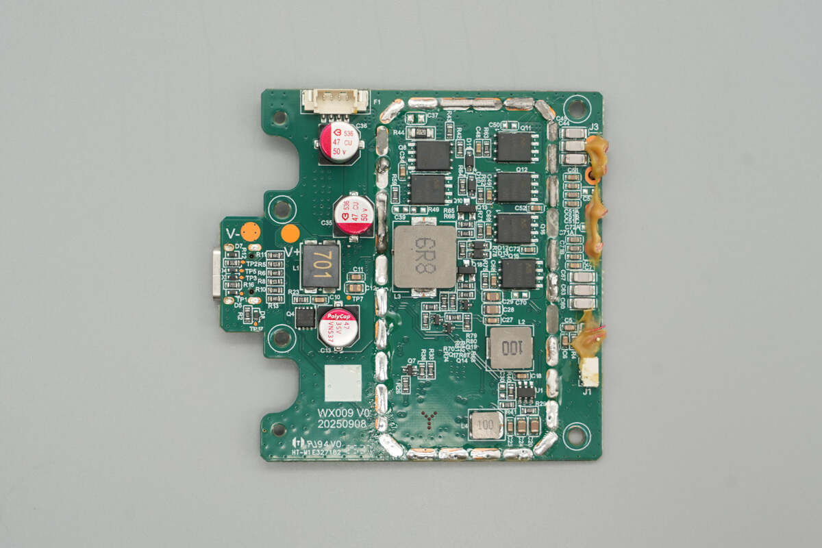
After removing the shielding cover, the area reveals synchronous boost MOSFETs, MOSFETs for switching the wireless charging coils, a synchronous buck converter, and multiple inductors.
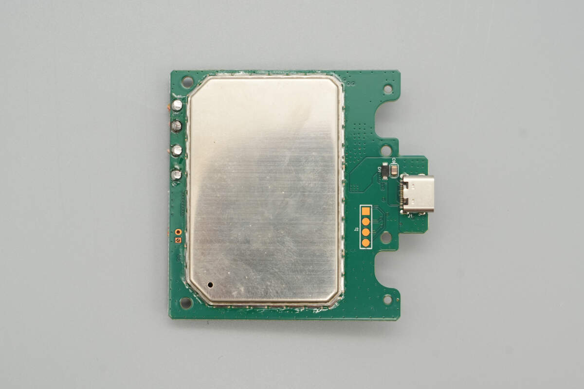
The back of the PCB is also covered by a shielding cover, with a USB-C socket soldered on the right side.
After removing the shielding cover, the area reveals the wireless charging master control chip, a clock crystal, and wireless charging power MOSFETs.
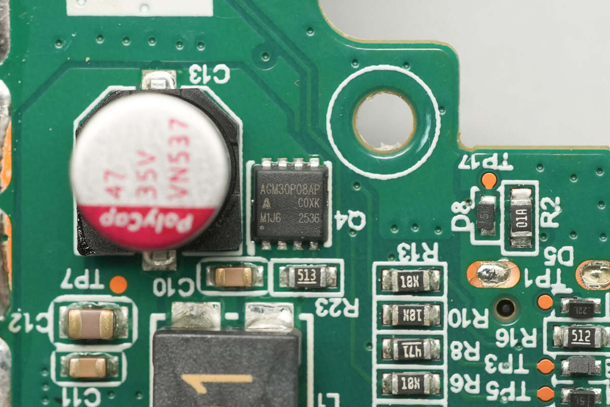
The input-side VBUS MOSFET is from AGMsemi, model AGM30P08AP. It is a PMOS with a voltage rating of –30 V and an on-resistance of 7.2 mΩ, housed in a PDFN 3.3 × 3.3 mm package.
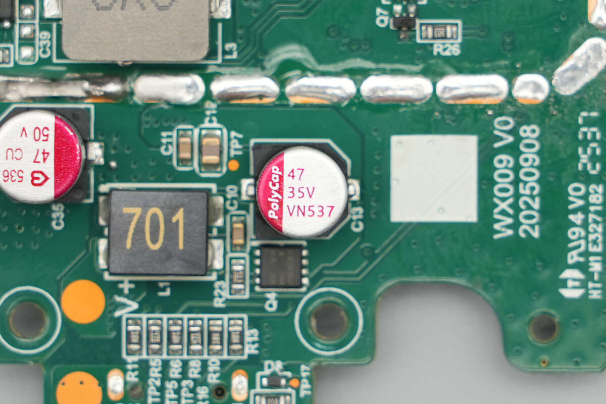
This solid capacitor is from PolyCap, with a specification of 35 V, 47 μF.
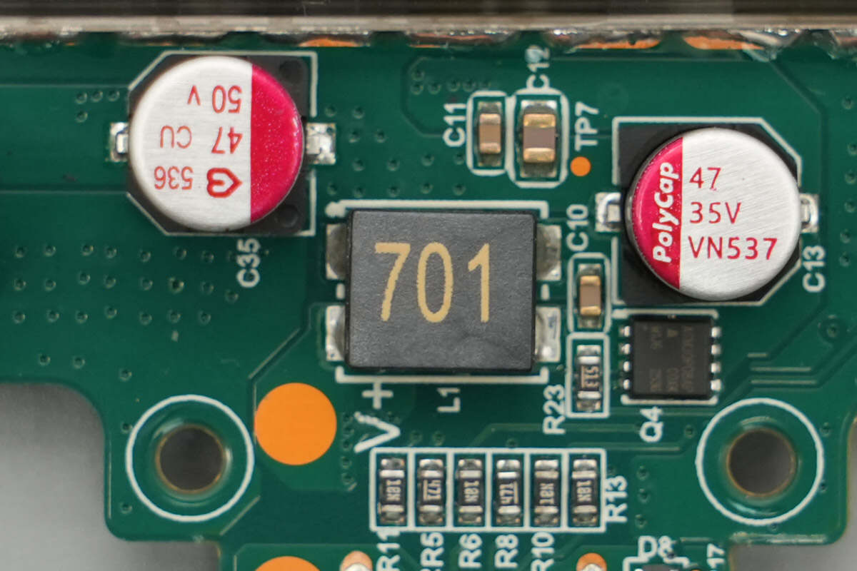
Close-up of the filter inductor.
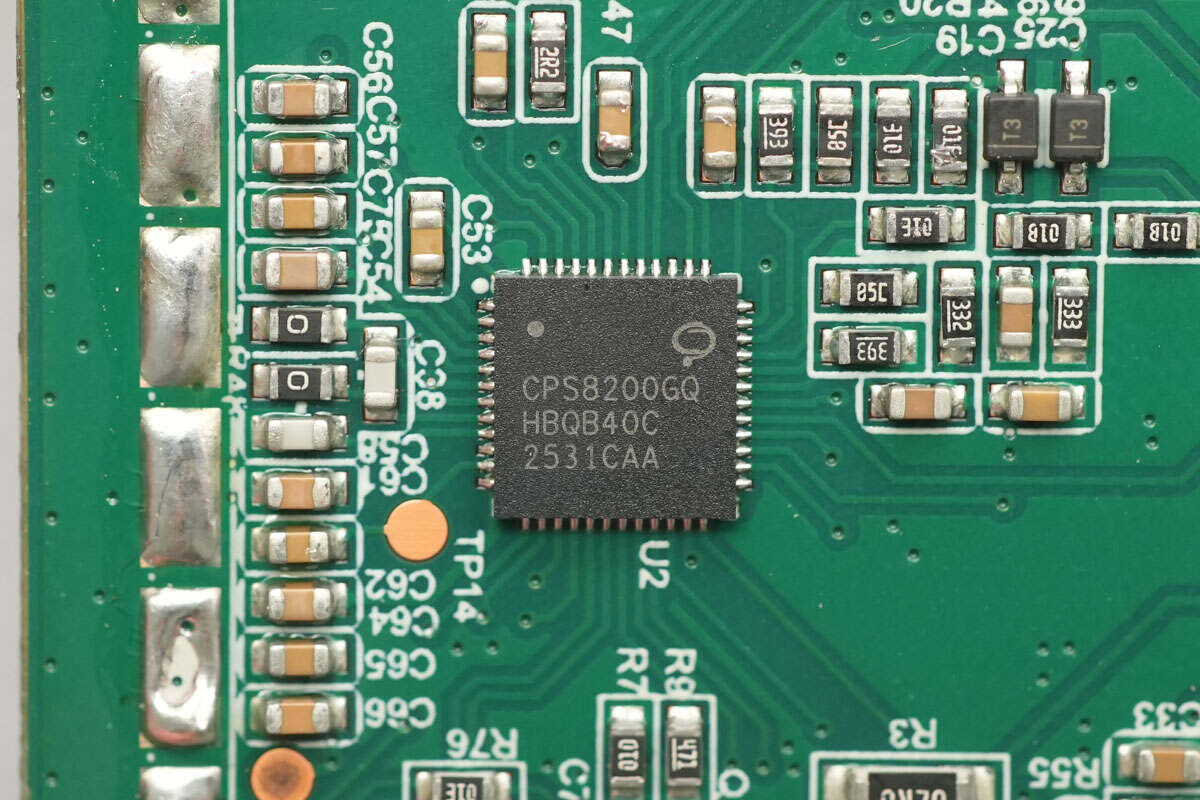
The wireless charging master control chip is the CPS CPS8200 from CPS. It is a highly integrated wireless charging transmitter chip featuring a 32-bit processor, 64 + 2 KB MTP, 32 KB ROM, and 2 KB SRAM. The MTP supports read/write protection and can be programmed via CC and DPDN. The chip provides two I²C interfaces and two UART interfaces. It also integrates a switching buck converter, linear regulator, DC-DC controller, full-bridge driver, communication module, and a multi-channel 12-bit ADC.
The CPS CPS8200 supports QC2.0/QC3.0, PD3.1, SCP, and AFC fast charging standards. Internally, it integrates three pairs of half-bridge drivers to support boost or buck conversion, and enables fixed-frequency voltage regulation charging. When paired with the corresponding MOSFETs, it can form a complete Qi2 wireless charger. The chip supports a 24 V supply voltage, with the power stage supporting up to 45 V. It also integrates over-voltage, over-current, and over-temperature protection functions.
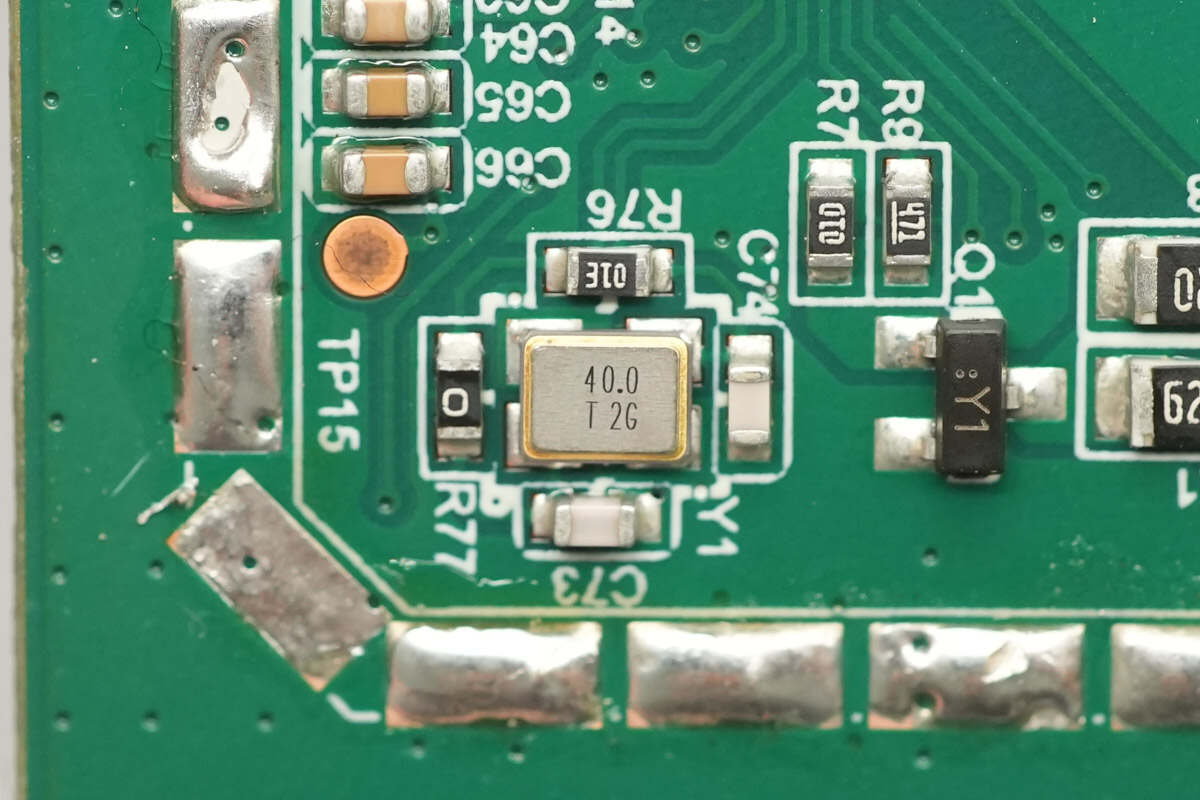
Close-up of the external 40.0 MHz clock crystal.
A 10 μH inductor is used for buck conversion to achieve self-powering.
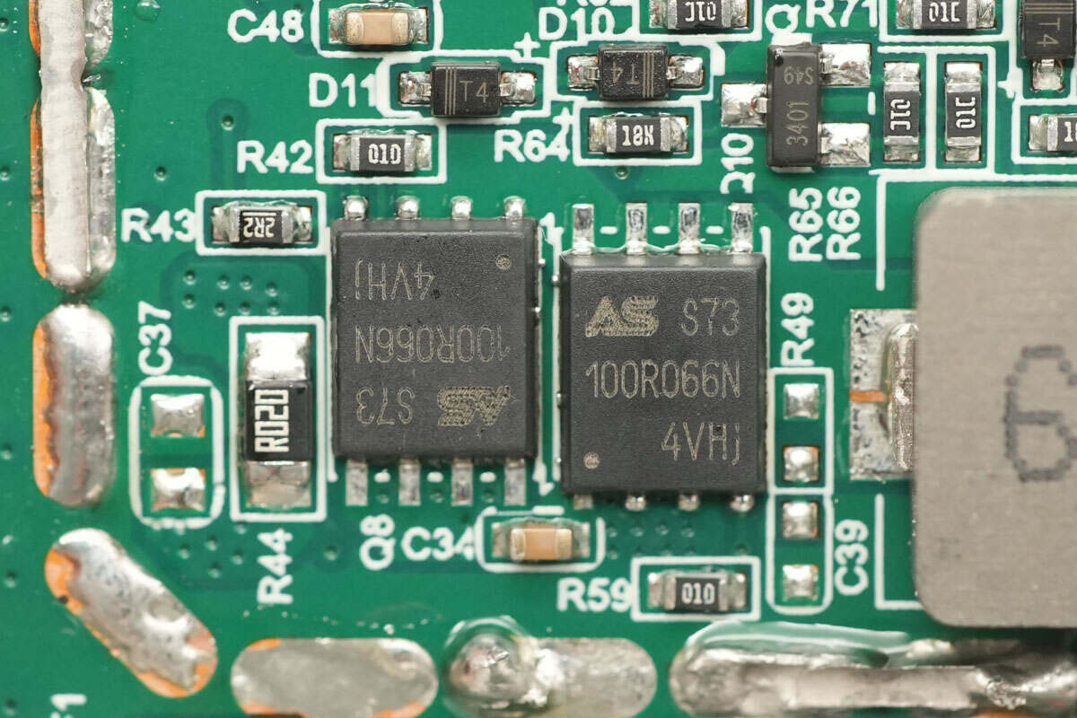
The synchronous boost MOSFETs are from ASDsemi, model ASDM100R066NQ. They are NMOS devices with a voltage rating of 100 V and an on-resistance of 5 mΩ, housed in a DFN 5 × 6-8 mm package.
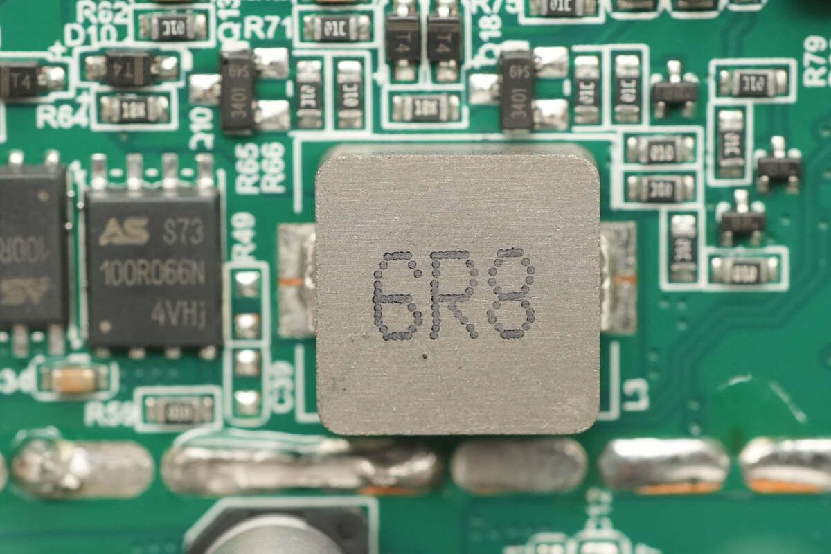
Close-up of a 6.8μH boost inductor.
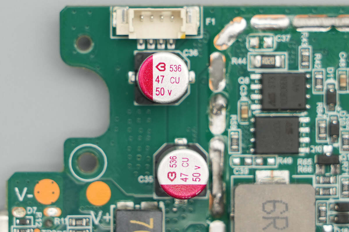
The two solid capacitors are from BERYL, each rated at 50V, 47μF.
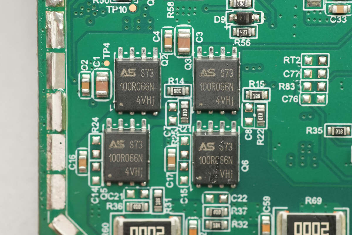
The four wireless charging power MOSFETs used are also ASDsemi ASDM100R066NQ.
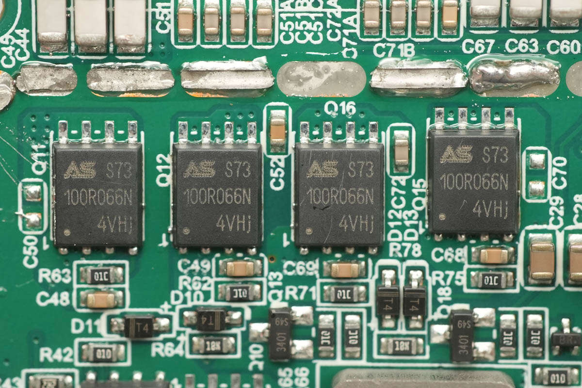
The other four MOSFETs used for switching the wireless charging coils are also ASDsemi ASDM100R066NQ.
Close-up of the NPO resonant capacitors.
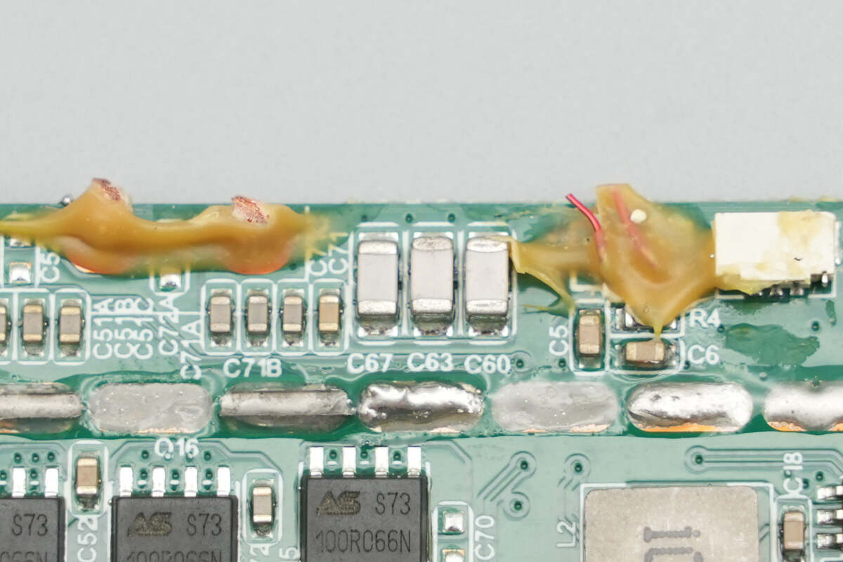
Close-up of another set of NPO resonant capacitors.
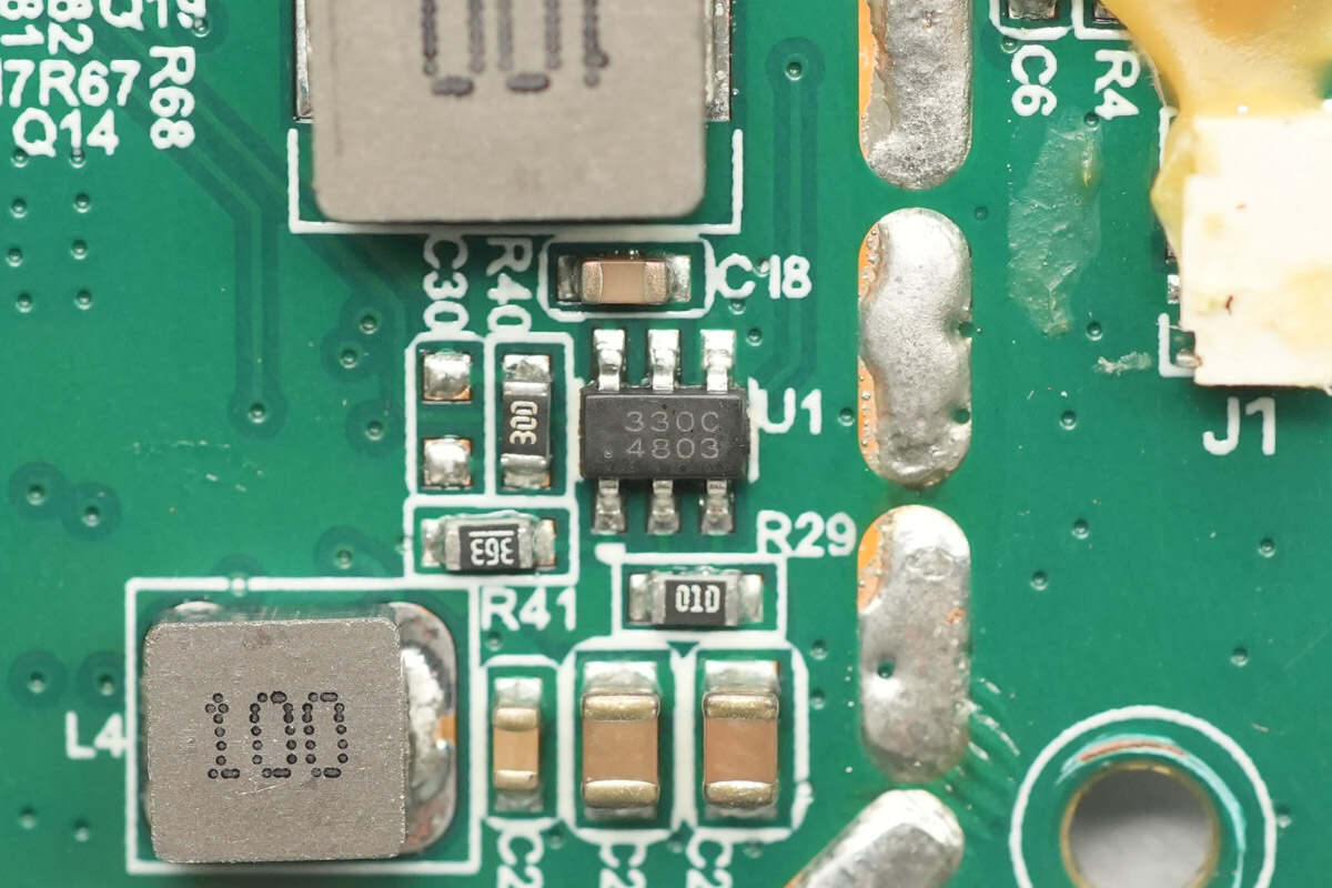
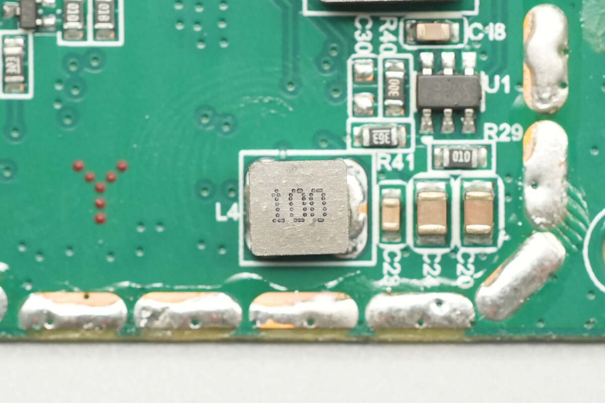
The synchronous buck converter used for step-down power is from Silicon, marked 330C, model SCT2330C. It supports an input voltage of 3.8–28 V and an output current of 3 A. The device integrates MOSFETs and provides output over-voltage and over-temperature protection. It comes in a TSOT23-6L package.
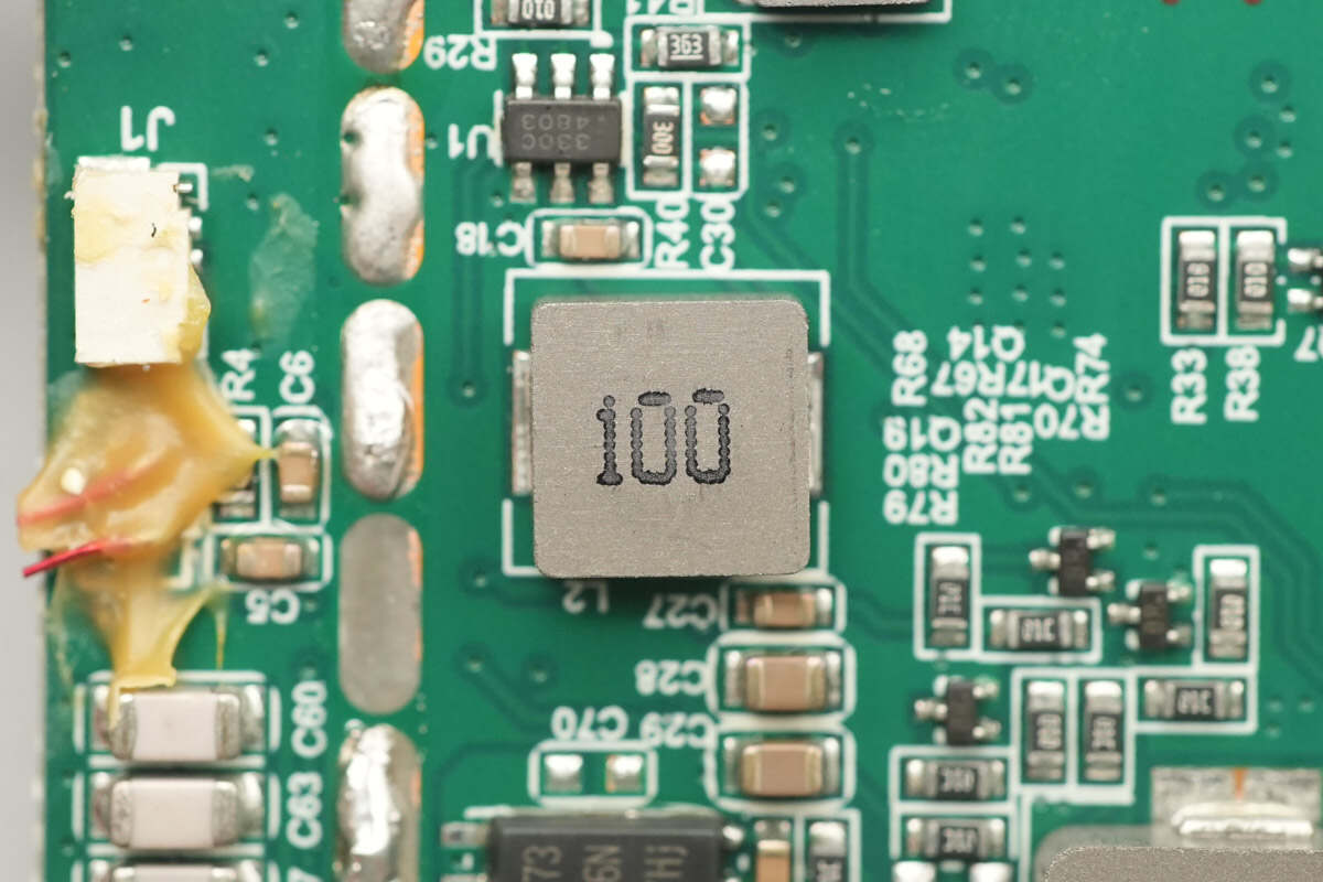
Close-up of the 10μH buck inductor.
Close-up of the wireless charging coils.
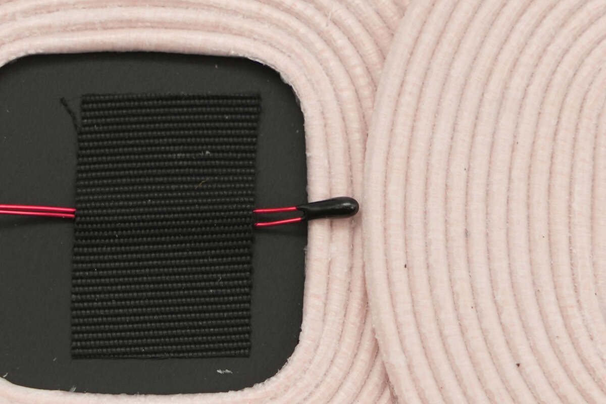
Close-up of the thermistor.
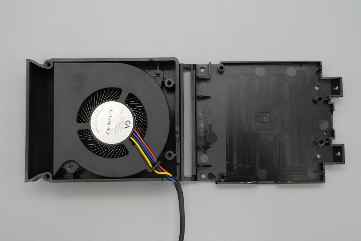
The cooling fan is enclosed by the casing.
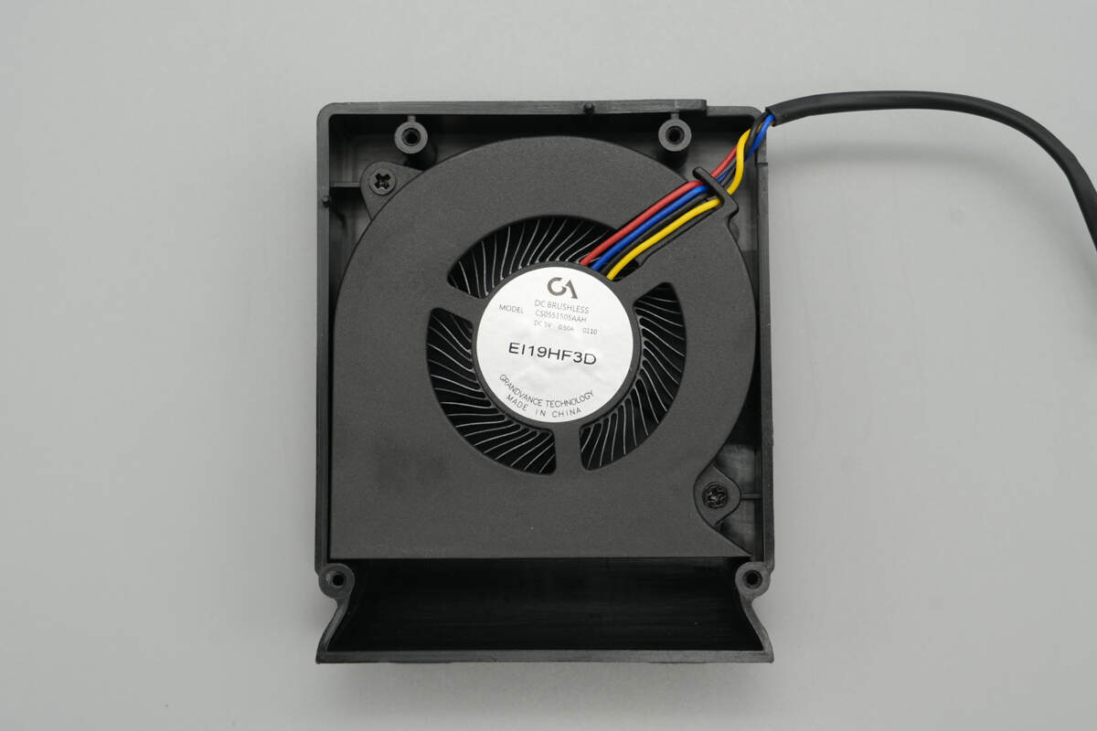
The cooling fan is from GrAndvance, model CS0551505AAH, rated at 5 V, 0.5 A.

Well, those are all components of the RedMagic 80W Air-Cooled Wireless Charging Dock.
Summary of ChargerLAB
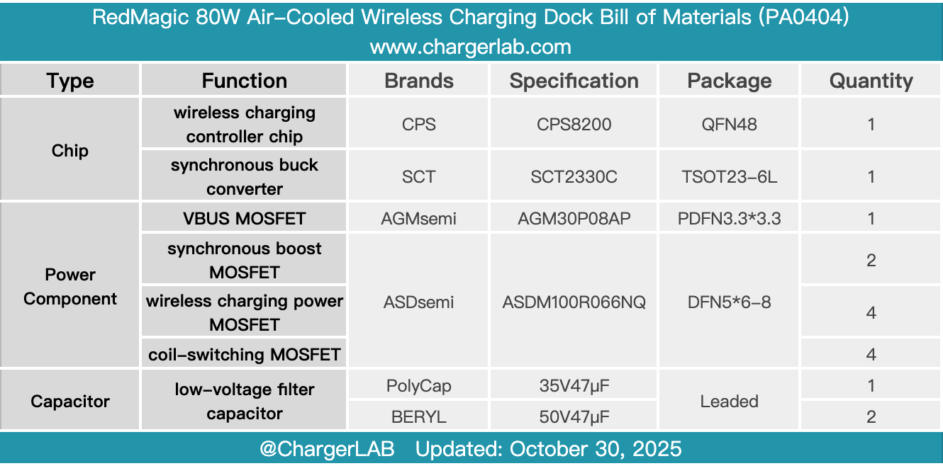
Here is the component list of the RedMagic 80W Air-Cooled Wireless Charging Dock for your convenience.
The angled upright design and built-in dual coils allow wireless charging in both horizontal and vertical orientations, while also serving as a phone stand. The integrated active cooling fan adjusts its speed according to the charging power, effectively reducing temperature rise and energy consumption.
After taking it apart, we found that it is designed based on the CPS CPS8200 wireless charging solution, paired with ASDsemi MOSFETs for input boost, wireless charging drive, and coil switching. BERYL and PolyCap capacitors are used for filtering. Both sides of the PCB are covered with shielding, and the coils are equipped with thermistors. The build quality and components are reliable.
Related Articles:
1. Teardown of Momax 45W 3-in-1 GaN Power Bank with Retractable Cable (IP167)
2. Teardown of Maxcellent Multi-Function Portable Jump Starter
3. Teardown of CUKTECH 10 Super Magnetic Power Card (WPB100P)