Introduction
Megmeet is a high-tech company specializing in power electronics and industrial control technologies. The company focuses on the research and development, production, sales, and service of hardware, software, and system solutions in the field of electrical automation. Its business encompasses custom power supplies, industrial automation, new energy vehicles, rail transit, smart home appliance control systems, precision connectivity, and intelligent equipment.
We have acquired a 15 kW EV charging power module from Megmeet, model MR750-20V. The module features a metal enclosure assembled with screws and affixed with an information label. It operates with a 380 V three-phase AC input and delivers an output voltage range of 250–750 V, an output current of 20 A, and a rated output power of 15 kW. This charging module supports hot-swapping. Fixing screws are located on both sides of the front panel, which also includes a handle and a cooling fan. The panel is equipped with status indicators and a load indicator for operational monitoring. Let’s take it apart to see its internal components and structure.
Product Appearance
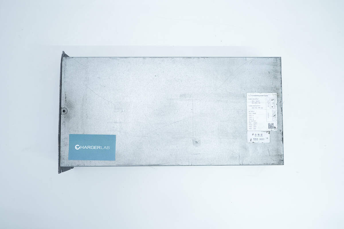
The Megmeet MR750-20V charging module features a metal enclosure with an information label affixed on the right side.
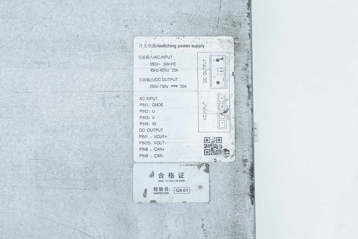
AC Input: 380 V\~ 3W+PE
45–65 Hz, 25 A
DC Output: 250–750 V, 20 A
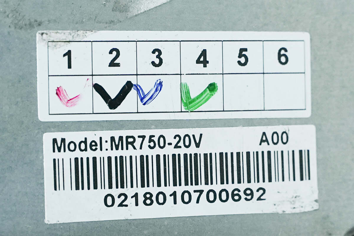
An information label is affixed to the side of the module, indicating the model number as MR750-20V.
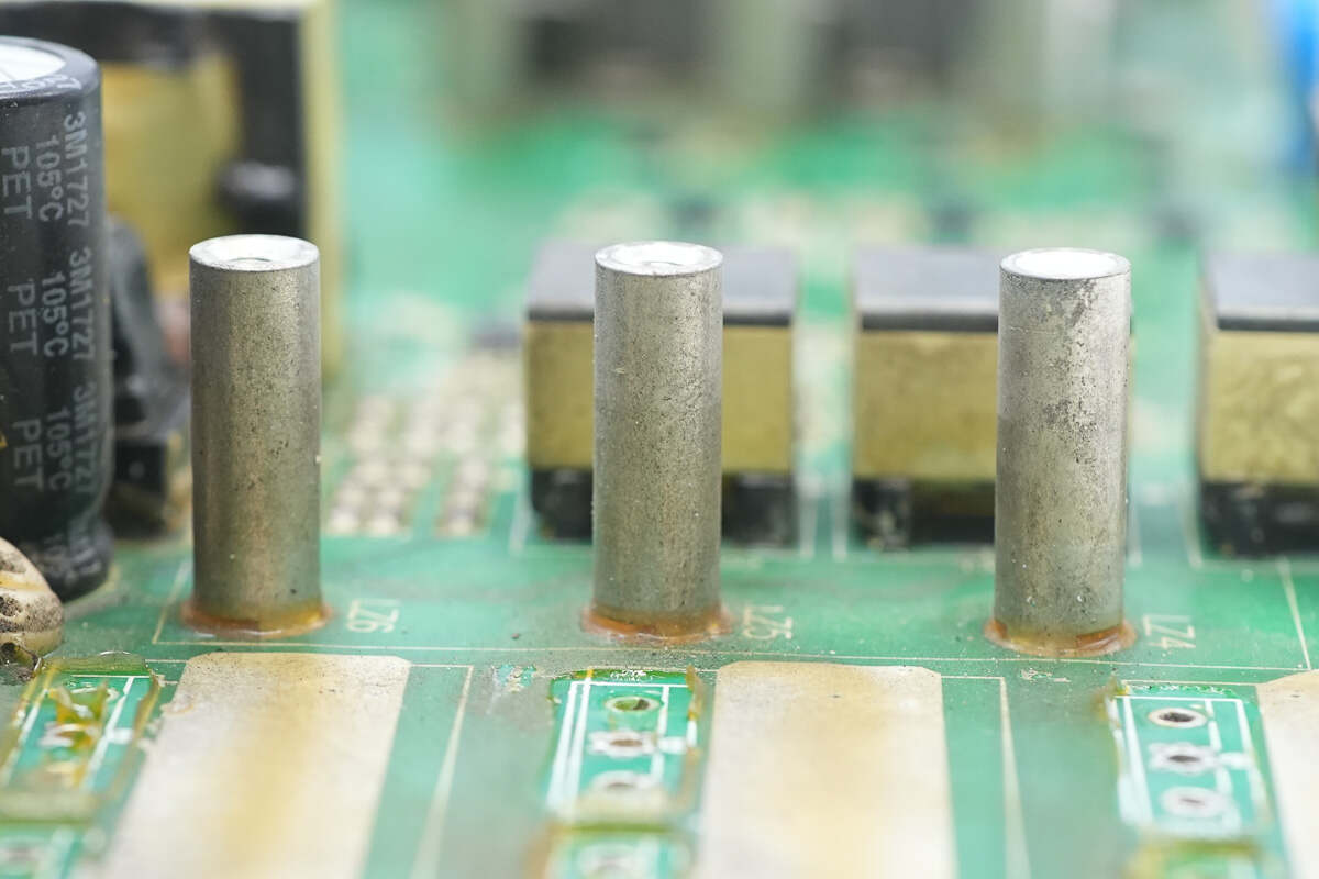
Inside the enclosure, mounting posts are provided for securing the module.
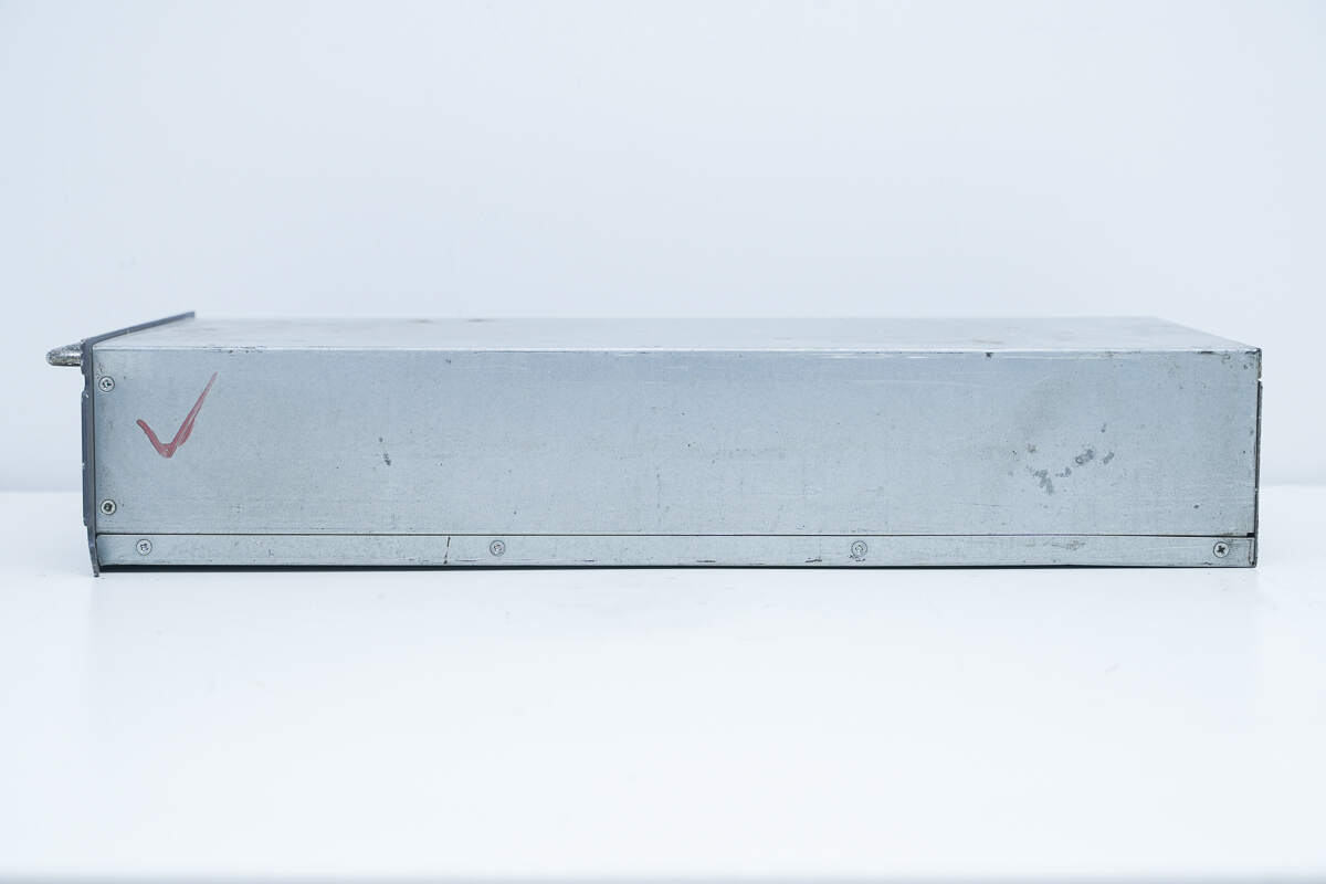
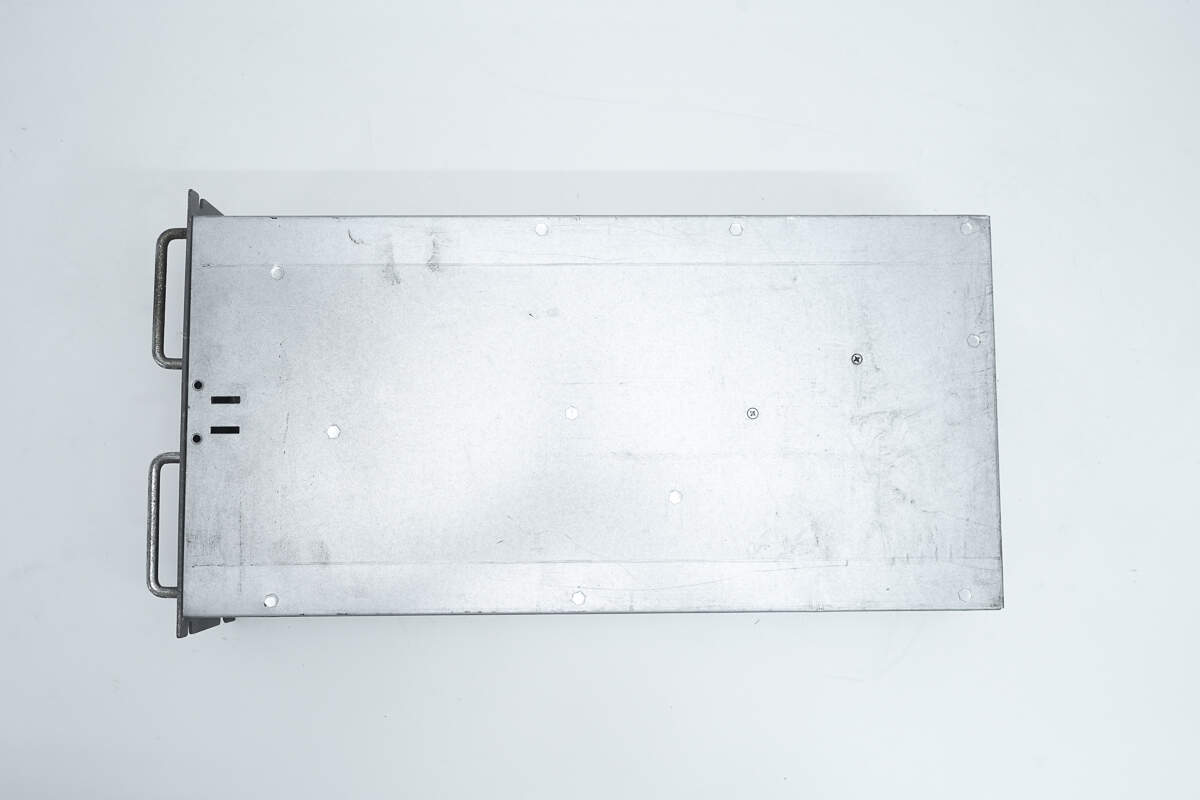
The sides are fixed with screws.
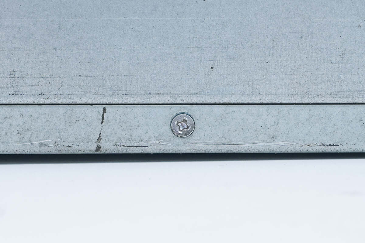
Close-up of the screw.
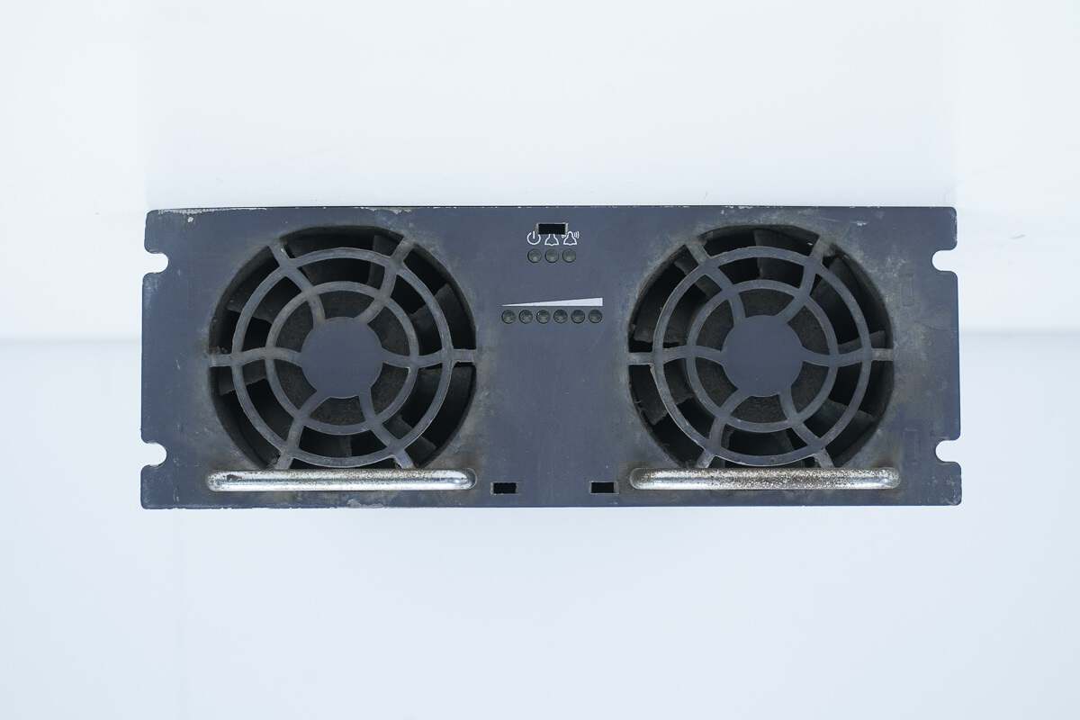
The front panel features cooling fans, a status indicator, and a load status indicator.
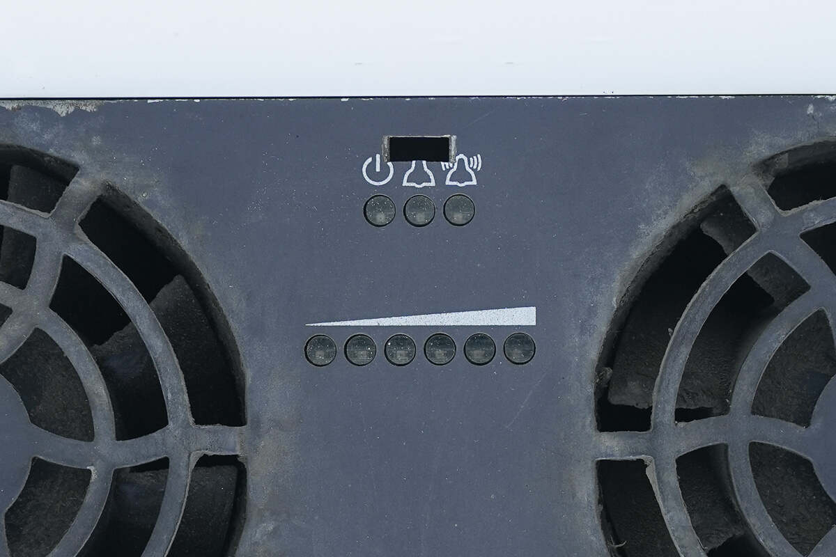
A close-up of the operation status indicator and load status indicator.
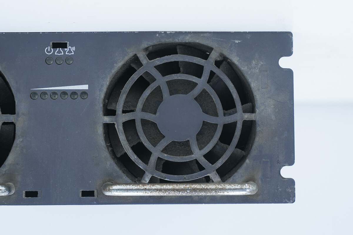
The cooling fans are located inside the grille.
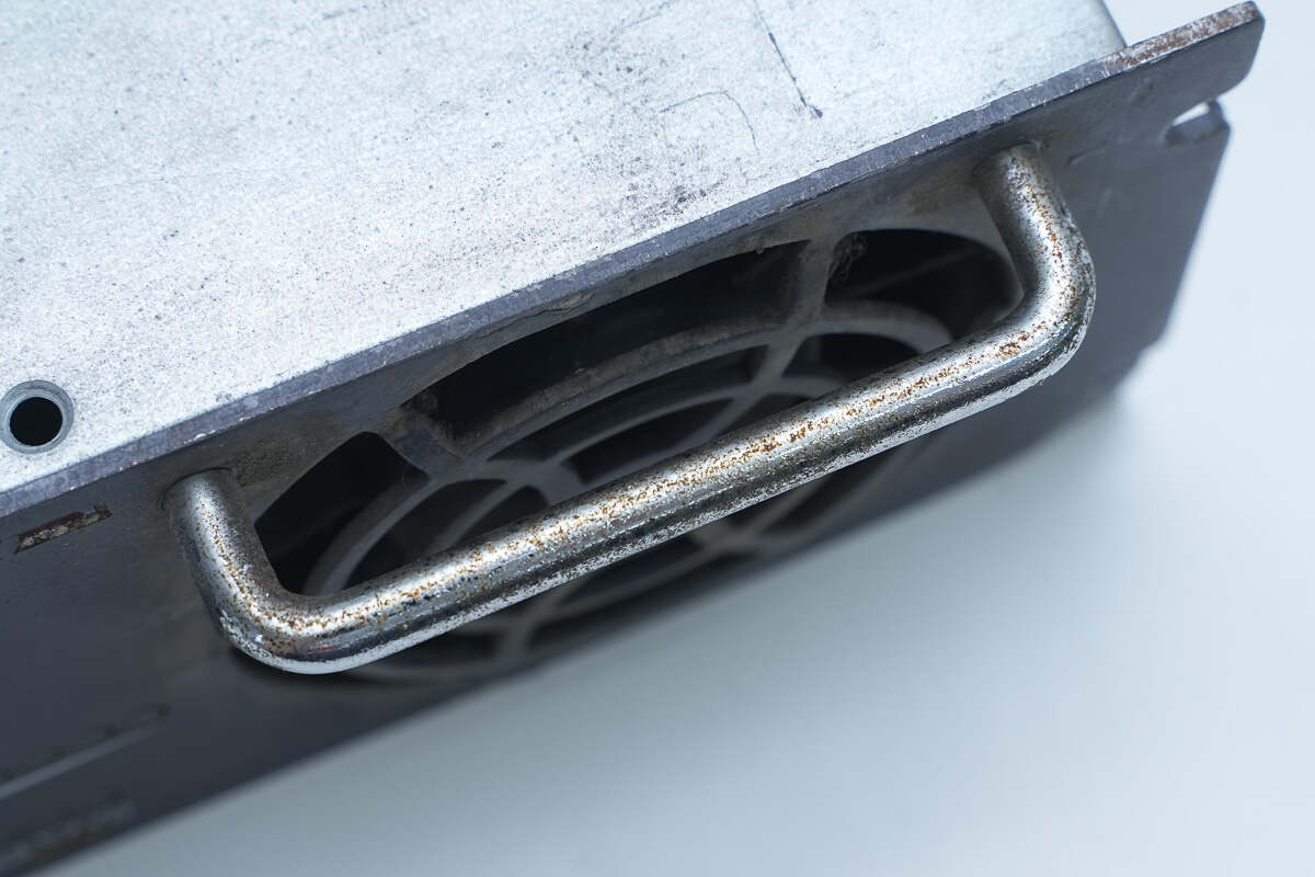
A close-up of the handle at the bottom.
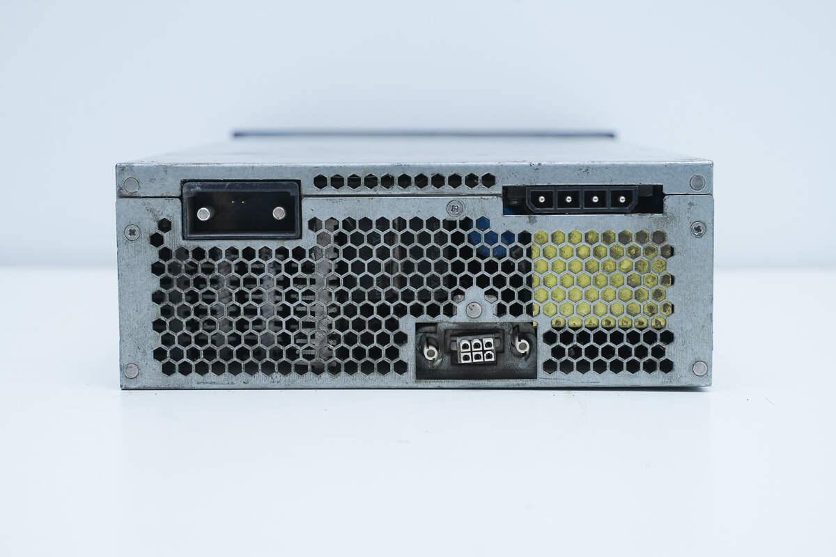
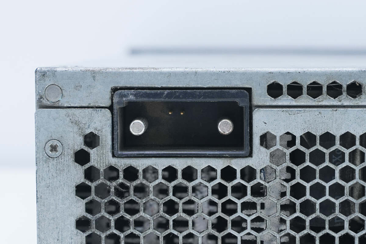
The rear panel features a DC output terminal, an AC input terminal, and a communication interface.
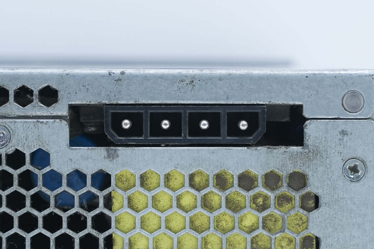
A close-up of the AC input terminal.
A close-up of the DC output terminal.
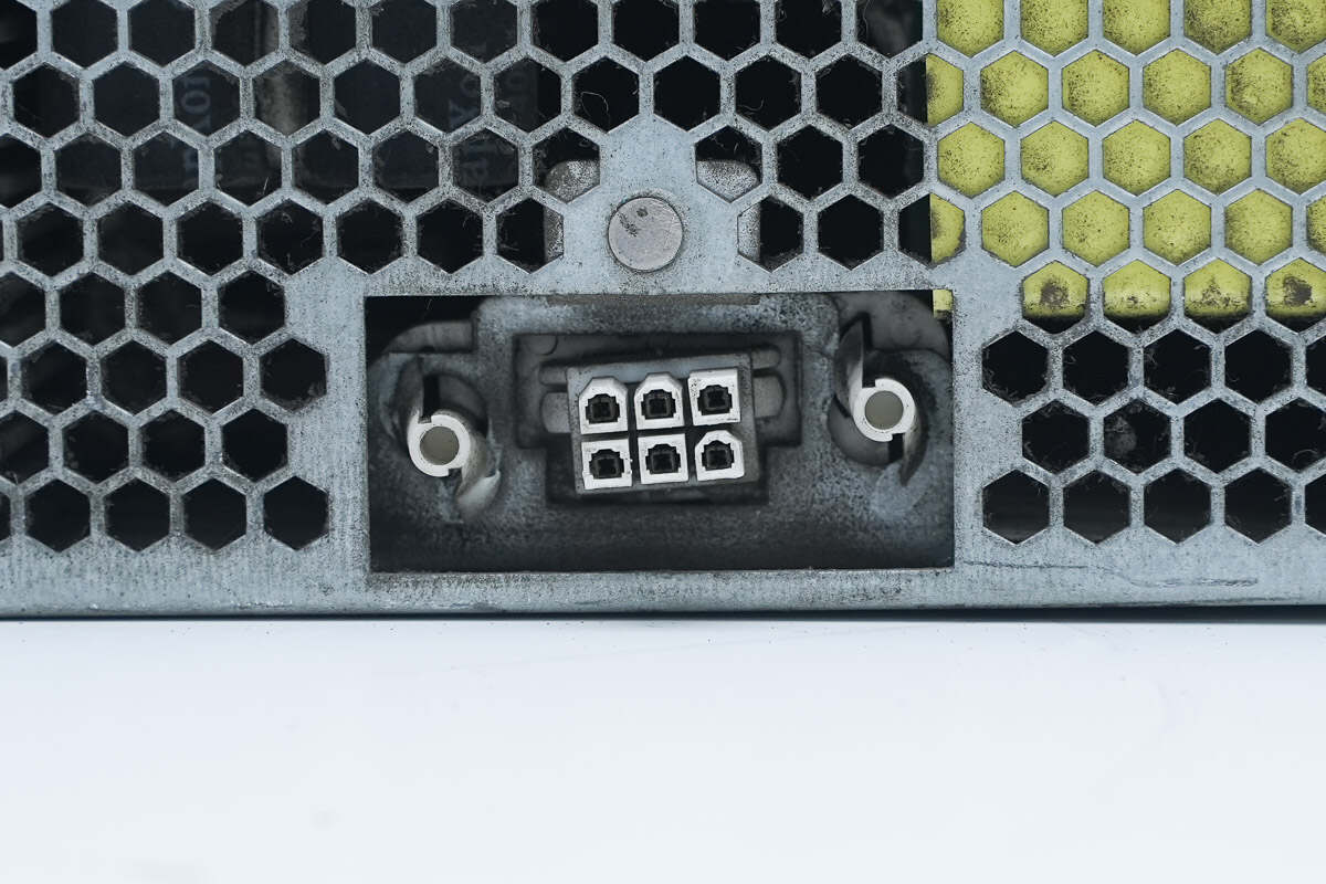
A close-up of the DC output terminal.
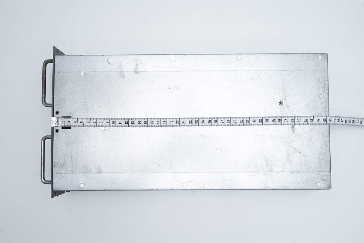
The length of the module is about 43.5 cm (17.13 inches).
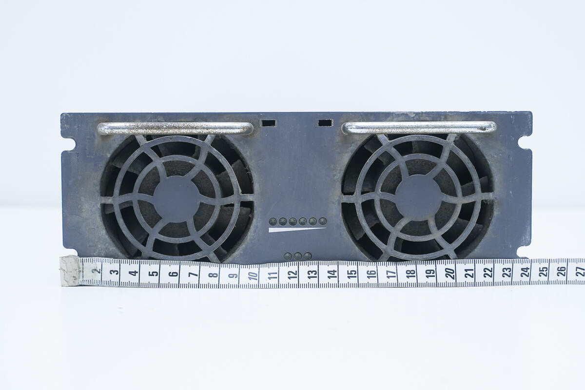
The width is about 24 cm (9.45 inches).

The thickness is about 8 cm (3.15 inches).
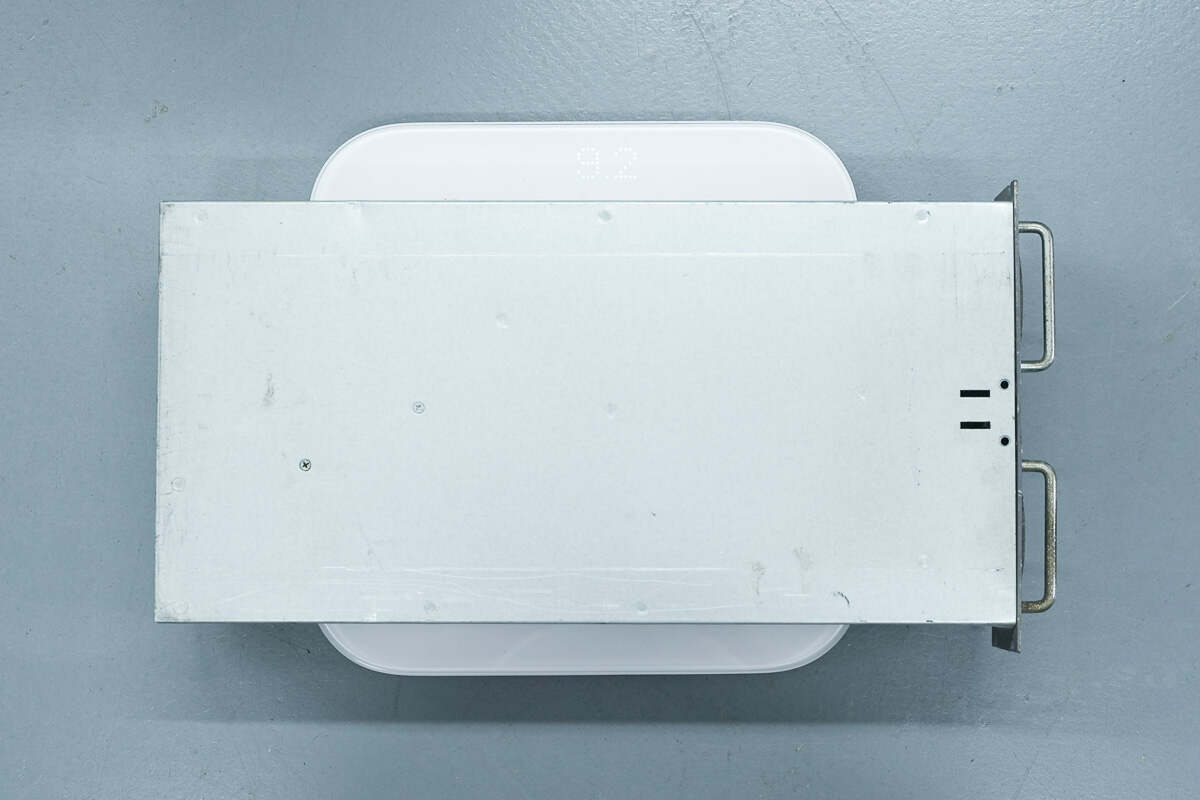
The weight is about 9.2 kg (20.28 pounds).
Teardown
Next, let's take it apart to see its internal components and structure.
First, unscrew the screws and remove the top cover.
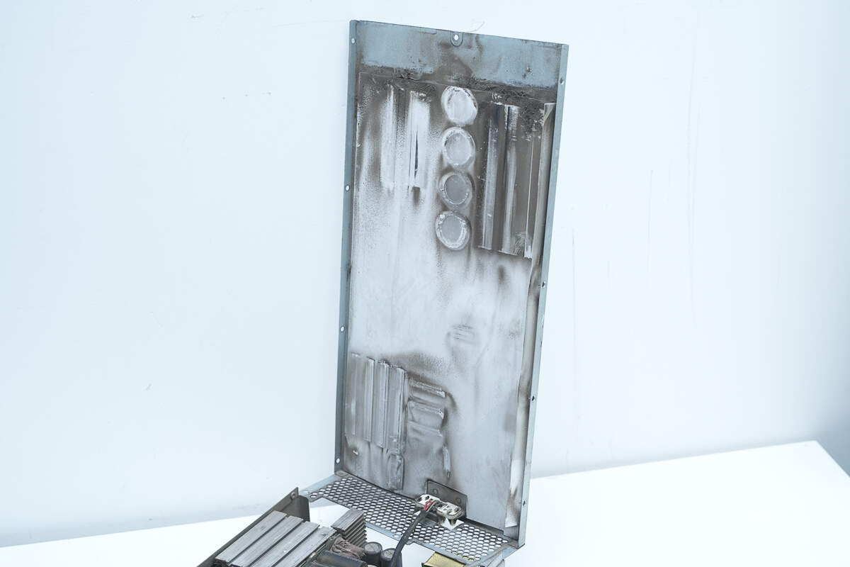
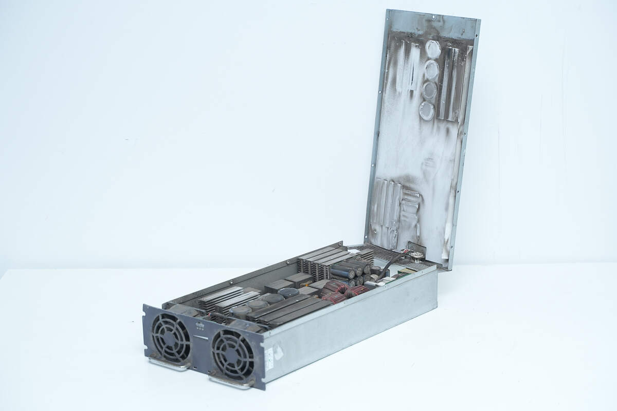
Inside the top cover, there is a white Mylar sheet used for insulation.
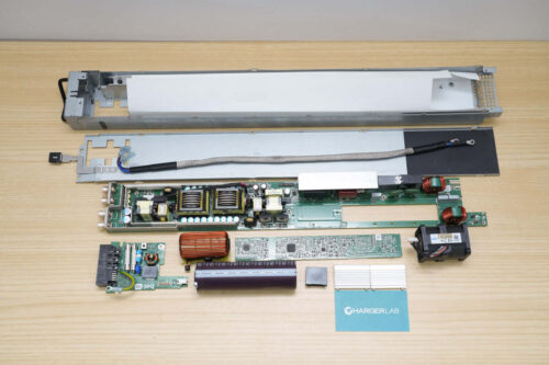
The interior features a single-layer PCB design, with a small PCB soldered to make efficient use of space. Additionally, a Mylar sheet is used for insulation and isolation between the PCBA module and the metal enclosure.
The communication interface is connected through a connector.
The front panel is also connected via a connector.
Disconnect the connectors, then remove the top cover and front panel.
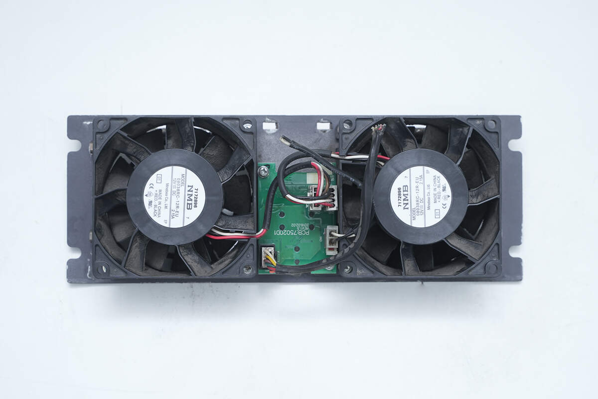
The front panel features a small indicator PCB and cooling fans.
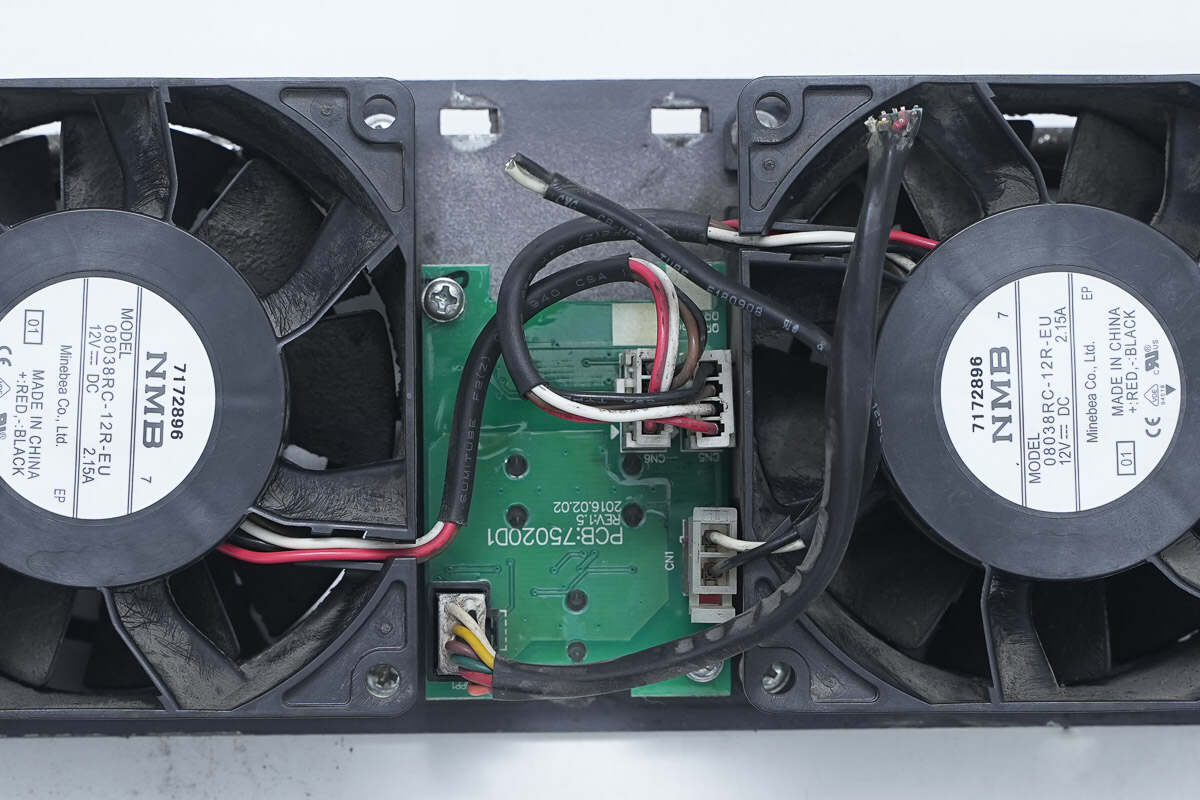
The cooling fans are connected to the small PCB via connectors.
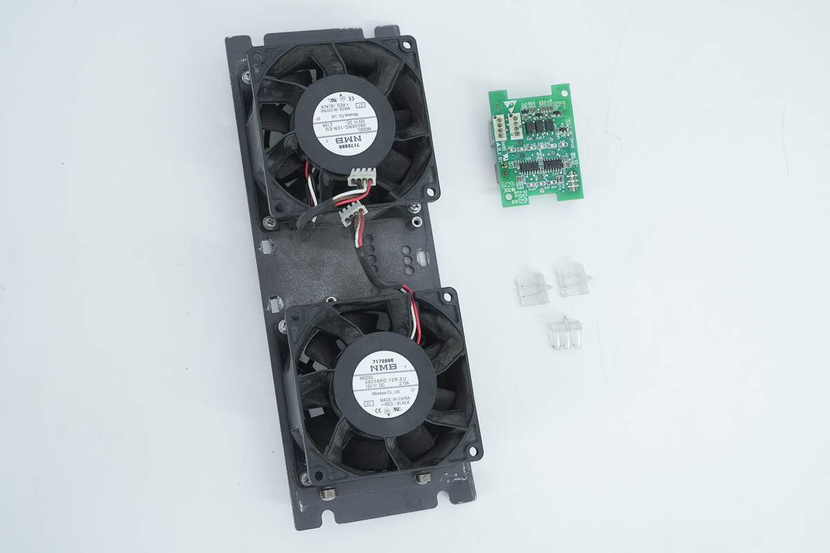
Remove the small PCB.
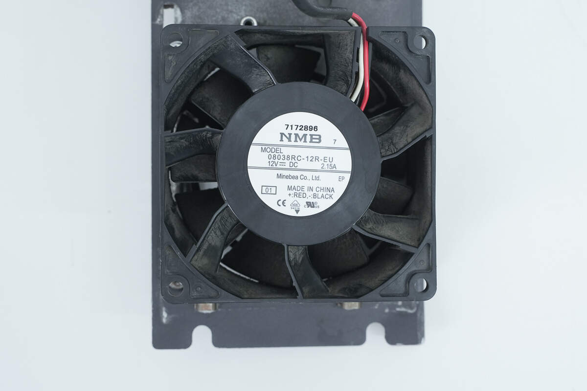
The cooling fan is from Minebea, model 08038RC-12R-EU, with a specification of 12V, 2.15A.

The front of the small PCB features an optocoupler, indicator lights, and a shift register.
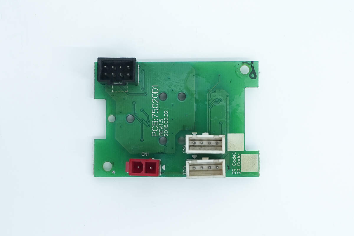
The back of the small PCB has the corresponding connectors.
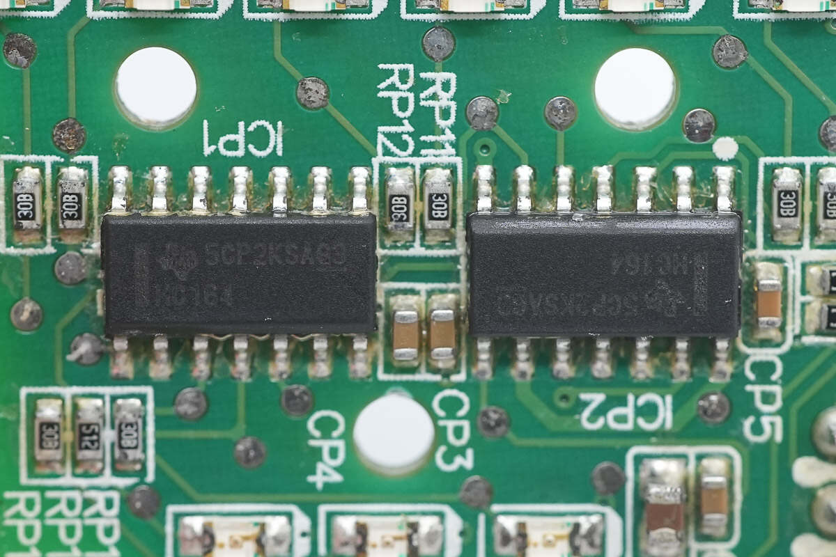
The two shift registers are from TI, marked with HC164, model SN74HC164, used for LED display driving, and they come in an SOIC14 package.
Three SMD LEDs are used for power and operation status indication.
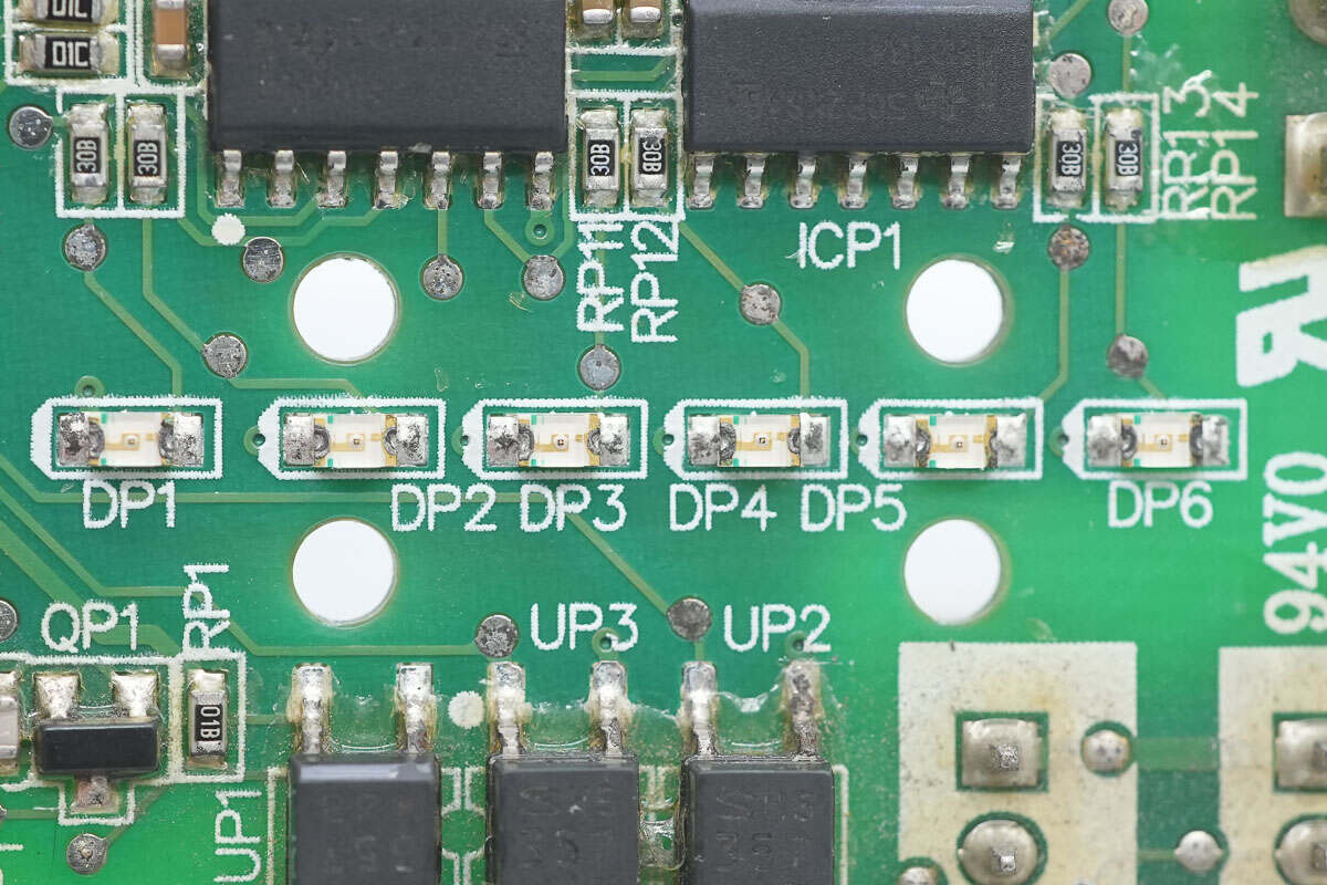
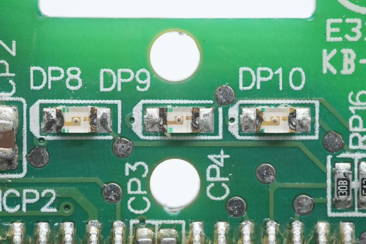
Six SMD LEDs are used for load status indication.
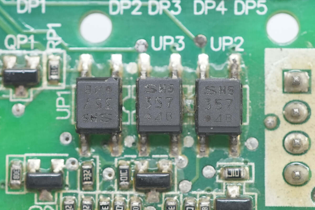
A close-up of the three Sharp PC357N optocouplers.
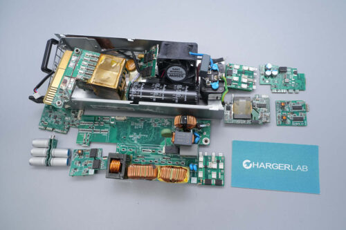
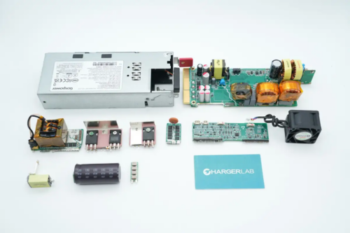
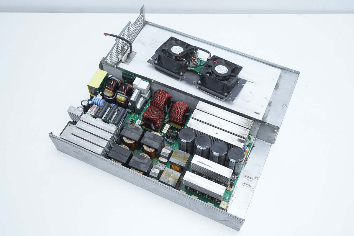
The PCBA module is secured inside the enclosure with screws.
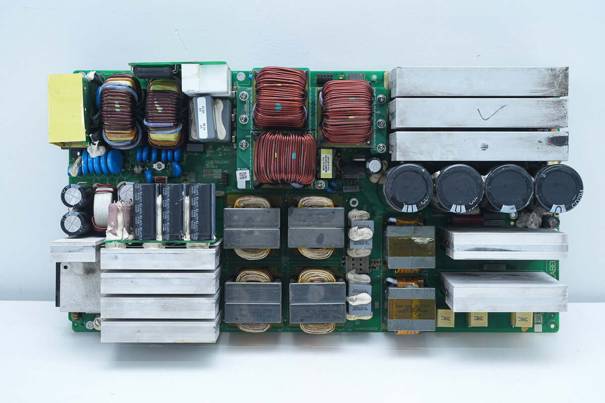
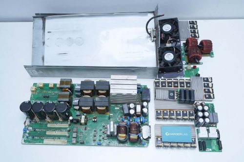
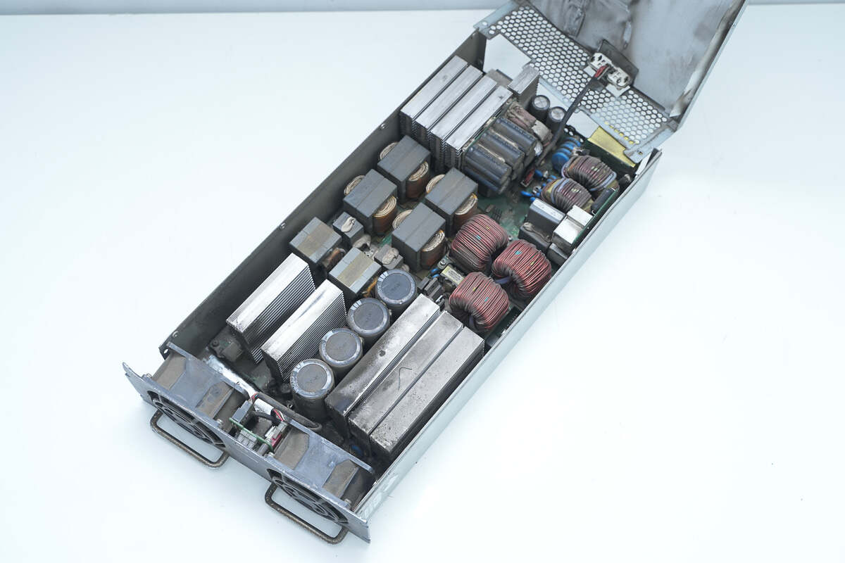
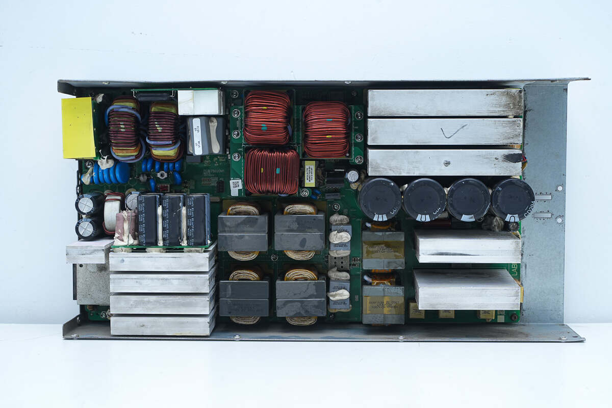
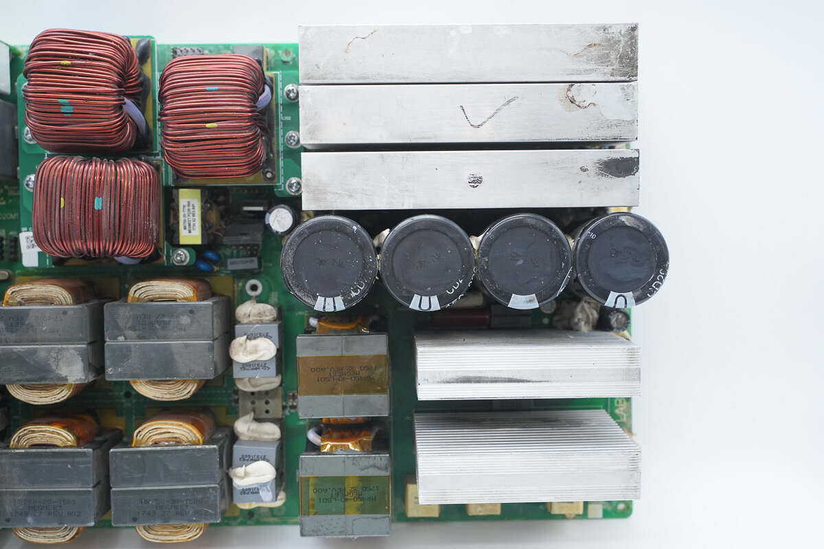
PCBA module has an AC input socket, safety X2 capacitor, fuse, varistor, and common mode choke on the upper left side. Above that, a small PCB with a soft start relay and resistor is soldered. In the middle, there is a PFC inductor small PCB. A heatsink for the PFC MOSFET and rectifier is on the upper right.
On the right middle, there are four electrolytic capacitors. A heatsink for the LLC MOSFET is at the lower right. To the left of the heatsink are a resonant inductor and capacitor. Four transformers are in the middle. The lower left has a DC output socket and a solid capacitor. Below the filter capacitors, a heatsink cools the output rectifiers.
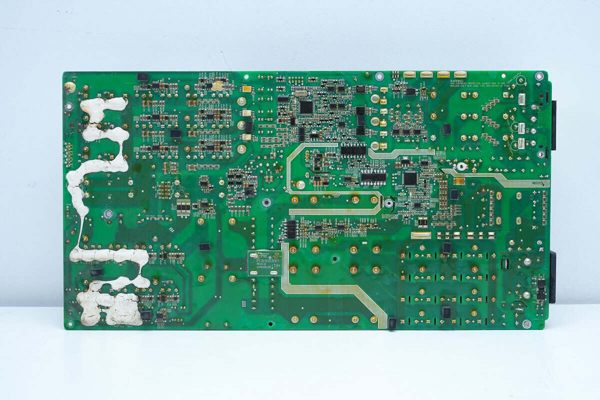
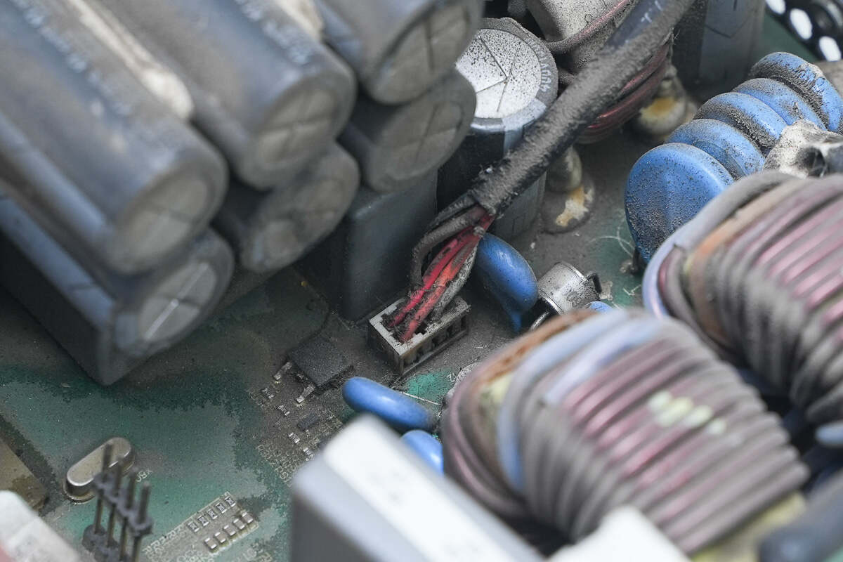
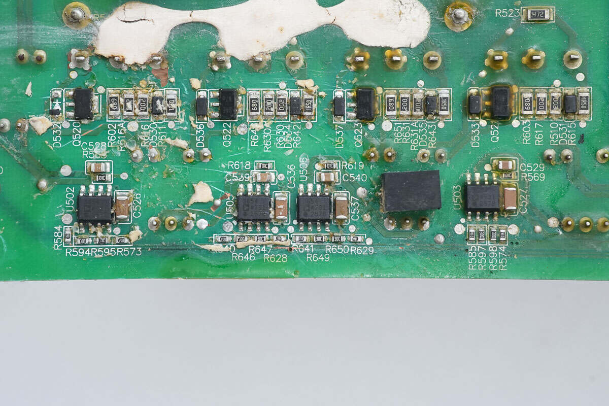
The back side has a PFC controller and MCU, along with corresponding isolation optocouplers and driver chips. The PCBA module is supported by adhesive pads, and the solder joints of SMD components near the air inlet are coated with glue for sealing and insulation protection.
A close-up of the AC power input socket.
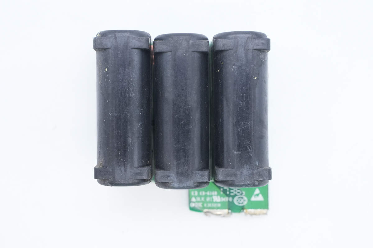
Three safety X2 capacitors are soldered on a vertical PCB.
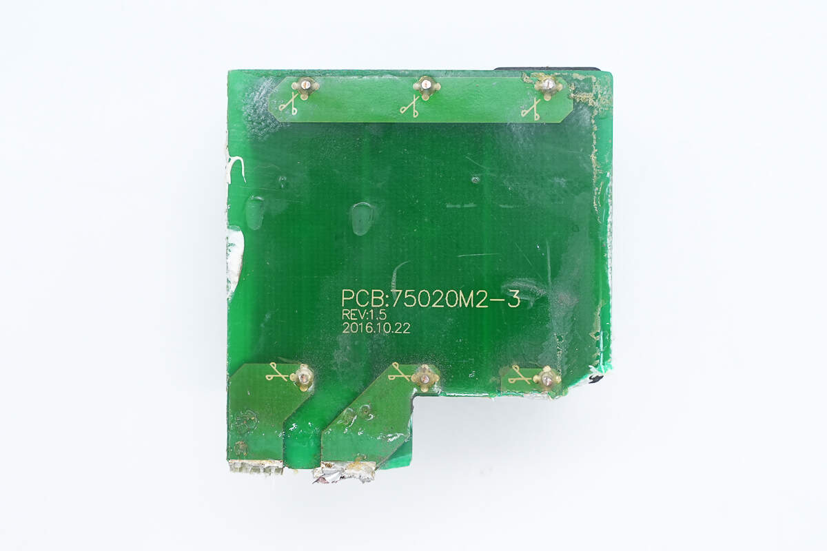
The back of the small PCB has no components.
The capacitor is from Faratronic. 5.6μF.
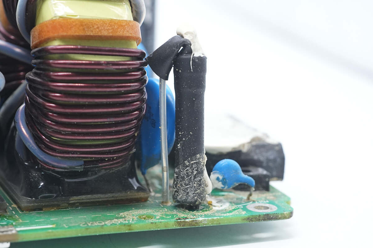
The fuse is insulated by heat-shrinkable tubing. 30A 250V.
A close-up of the other two fuses.
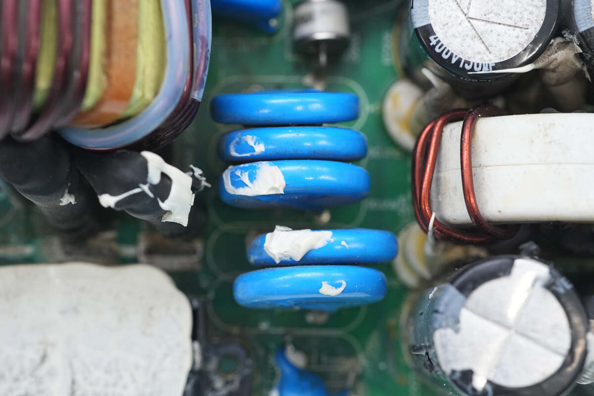
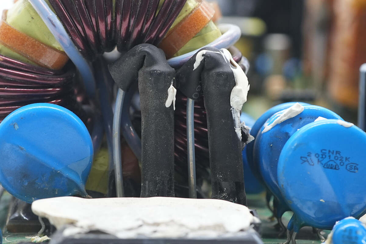
Five varistors are used to absorb overvoltage surges.
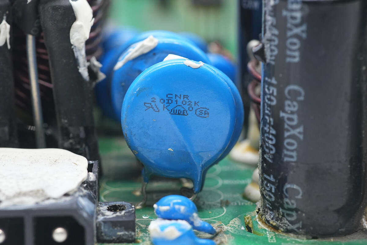
The varistors are from CNR, model CNR-20D102K.

A close-up of the gas discharge tube in series with the varistors.
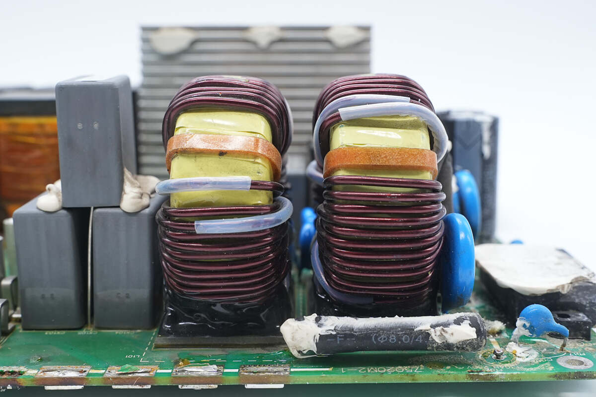
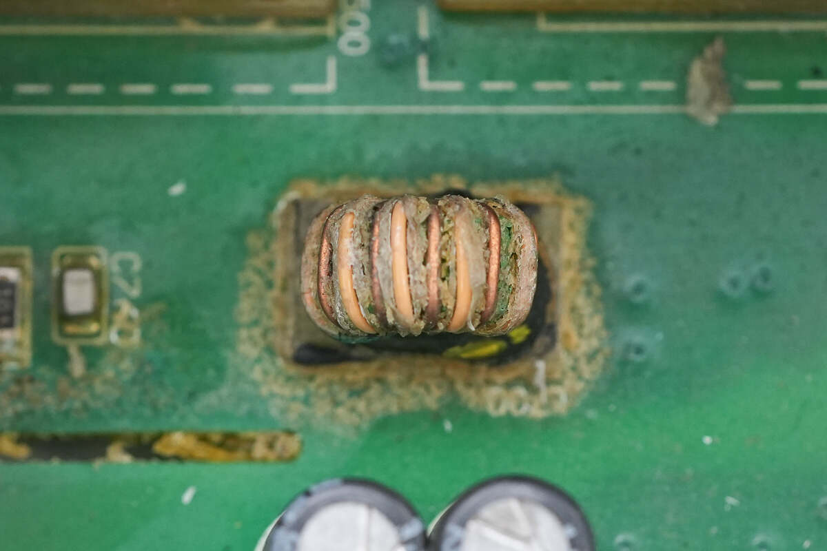
The common mode choke is wound with magnet and insulated wires, and it's also insulated with bakelite.
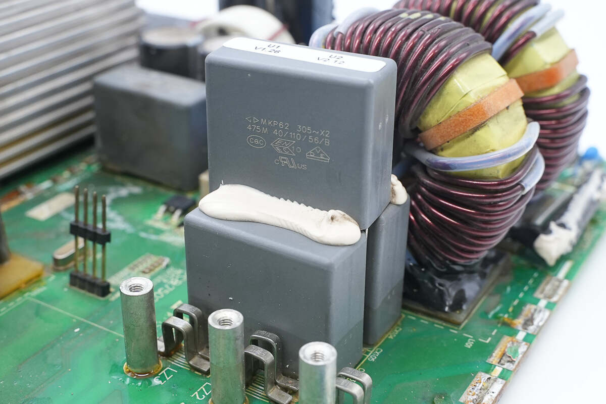
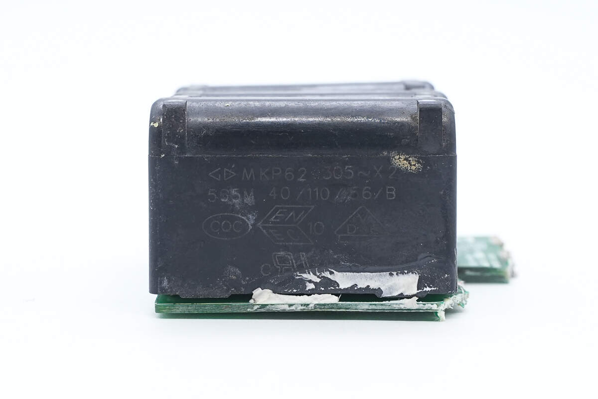
The safety X2 capacitor is from Faratronic. 4.7μF.
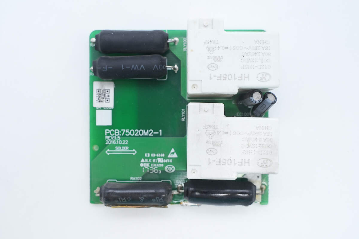
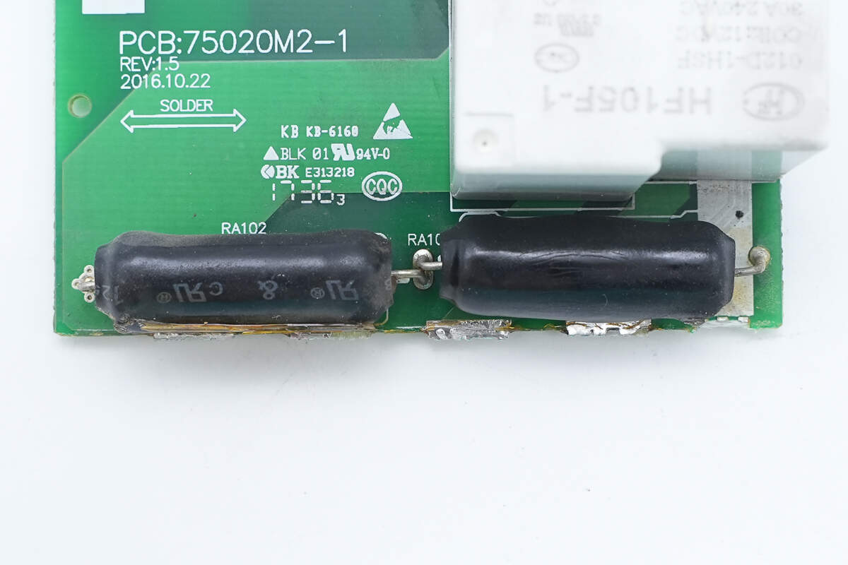
An overview of the soft start resistor and relay small PCB.
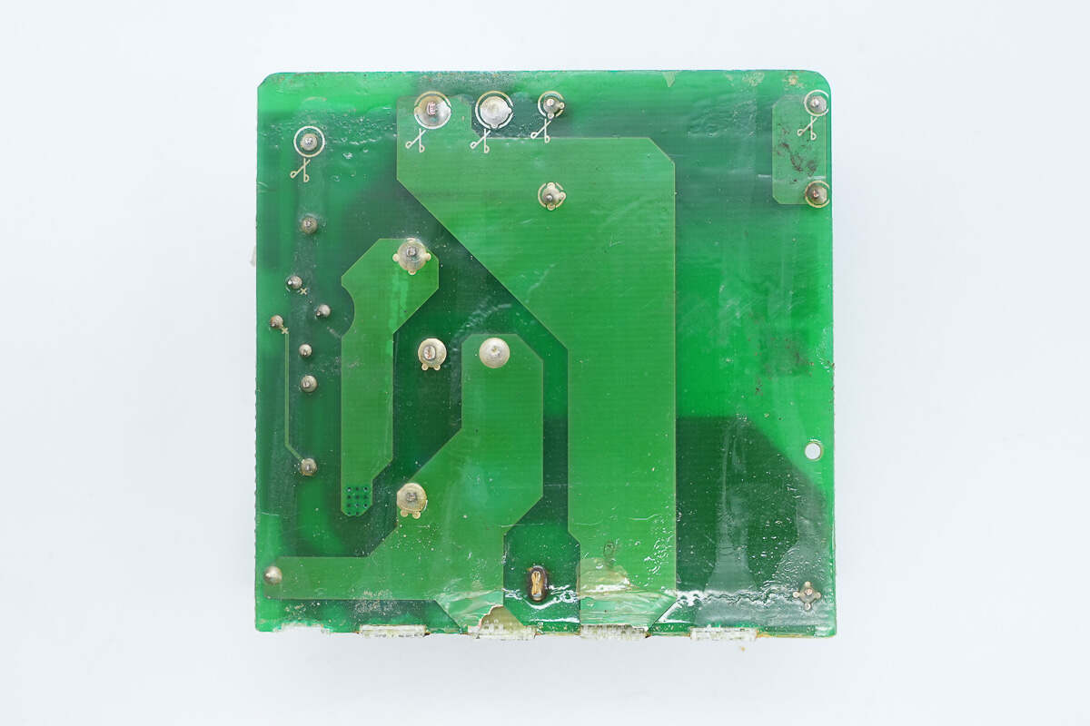
The back of the small PCB has no components.
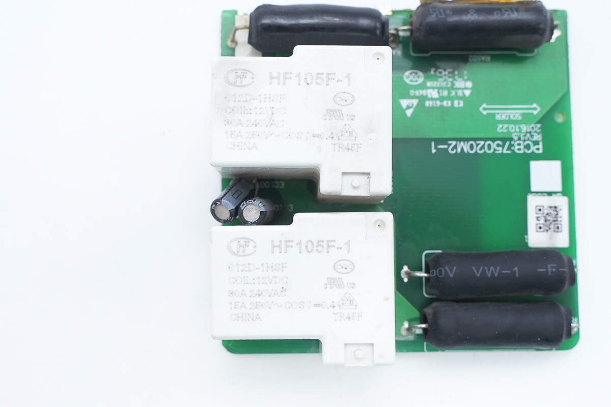
The relay is from HONGFA, model HF105F-1/012D-1HSF. It is a small, high-power relay with a coil voltage of 12V, featuring a set of normally open contacts with a contact rating of 30A.
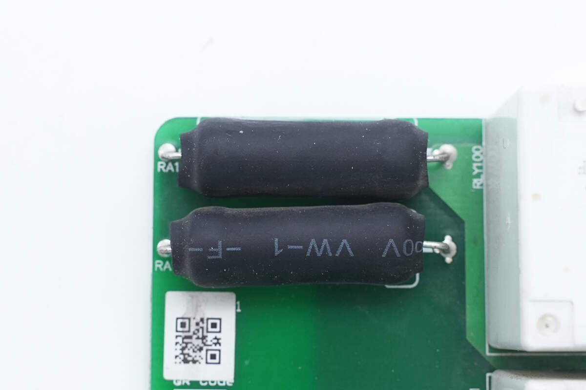
The two soft-start resistors in series are insulated by heat-shrinkable tubing.
A close-up of the other set of soft-start resistors.
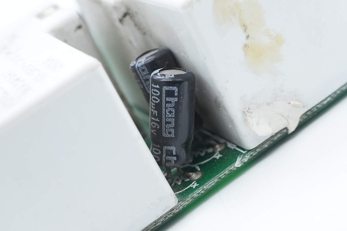
The two electrolytic capacitors have a specification of 100μF, 16V.
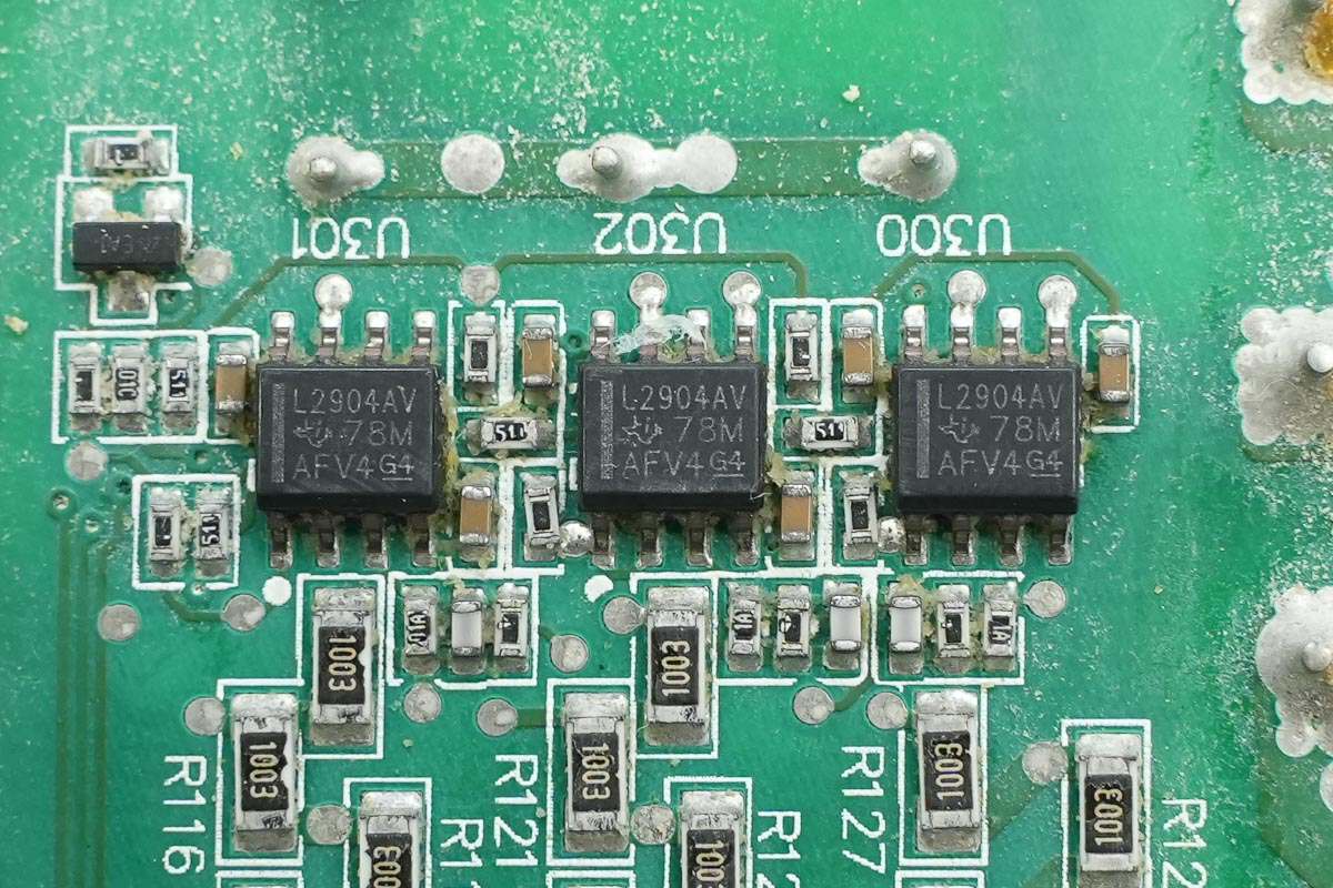
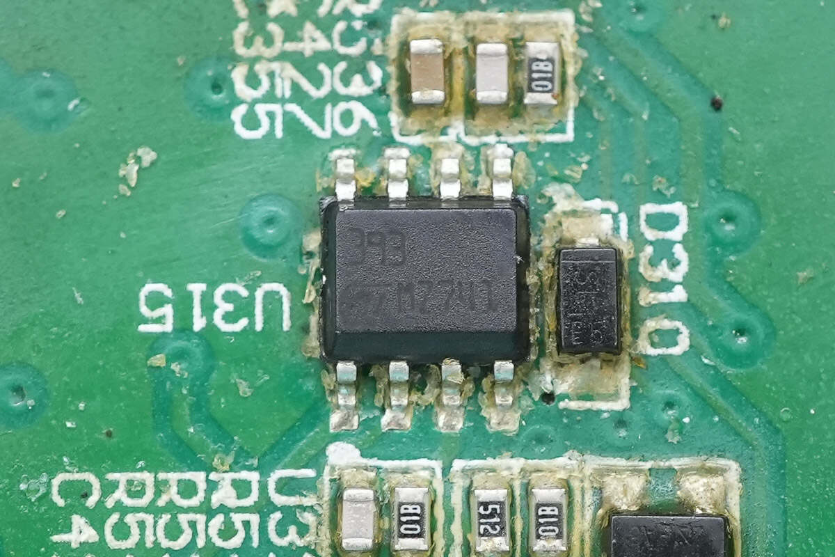
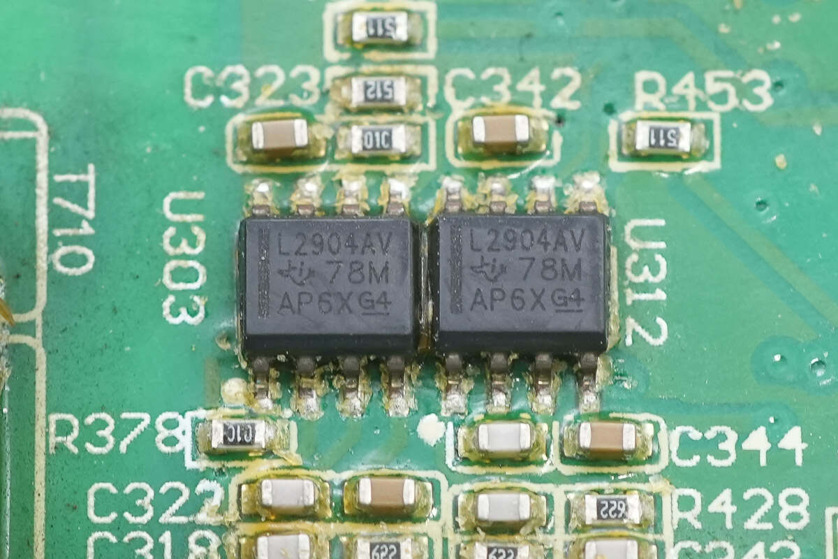
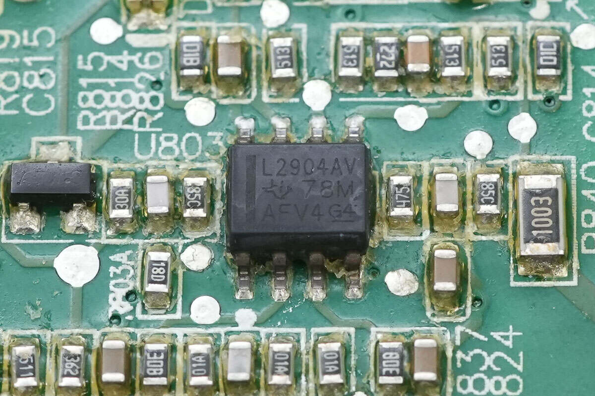
The three operational amplifiers are from TI, model LM2904AV. It is a standard dual op-amp, supporting a 3–30V operating voltage range, and comes in an SOIC8 package.
The input current sensing resistors are 6mΩ, with two resistors connected in parallel.
Three isolation amplifiers are used for input current sampling.
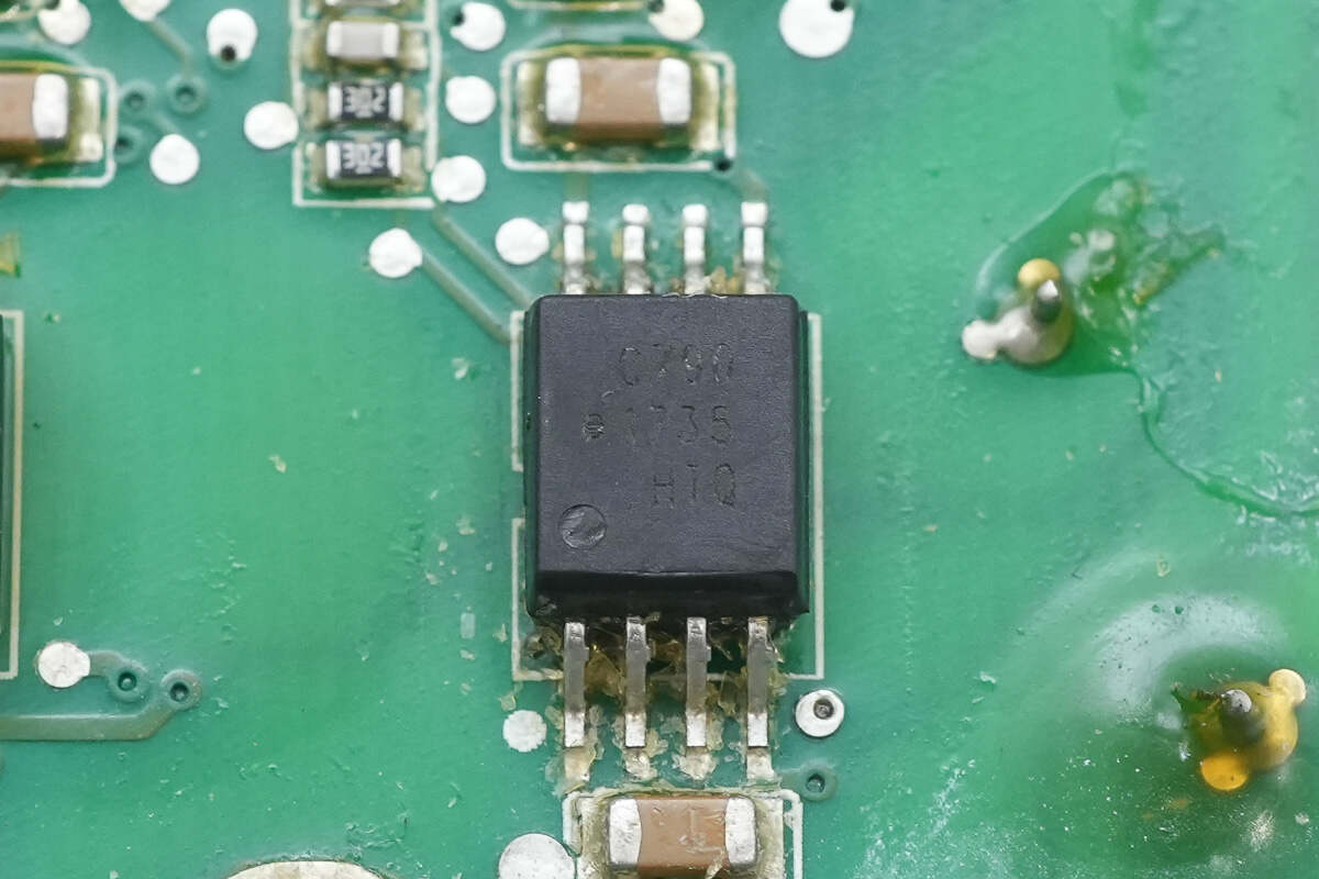
The isolation amplifiers are from BROADCOM, model ACPL-C790-500E. They use opto-coupling technology for isolation, feature differential output, and come in an SSO-8 package.
A close-up of the voltage comparator used for three-phase current detection.
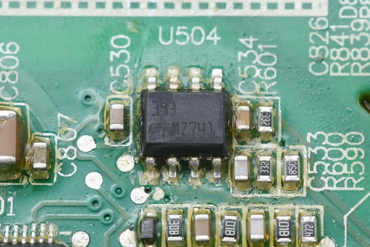
The voltage comparator is from STMicro, model LM393, and comes in an SO8 package.
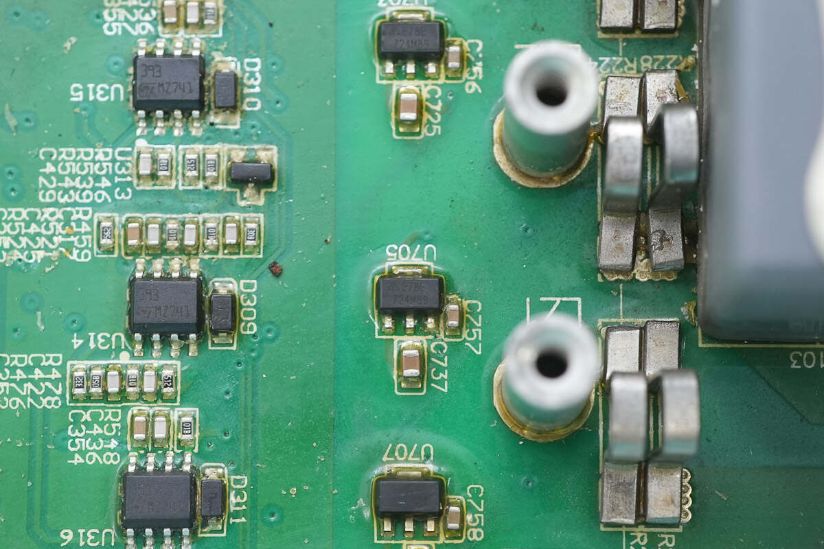
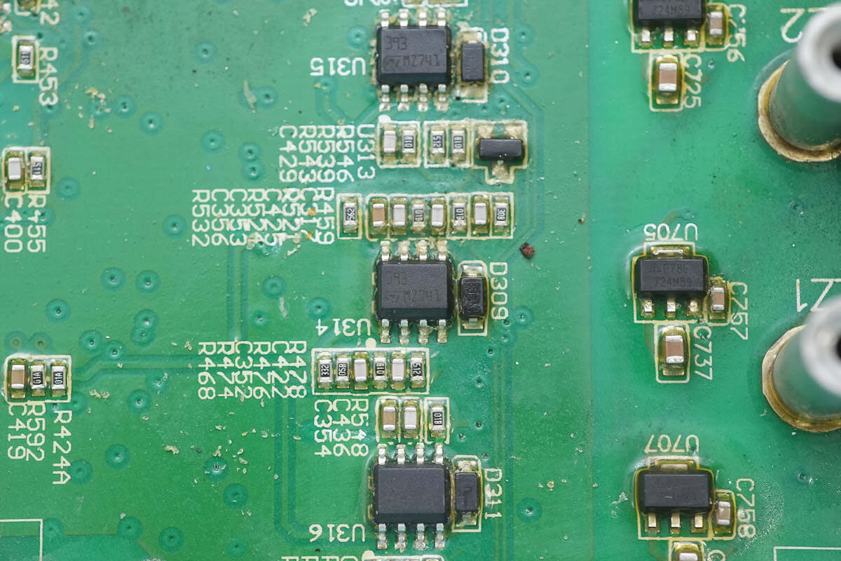
A close-up of the three voltage regulator chips that power the isolation amplifiers.
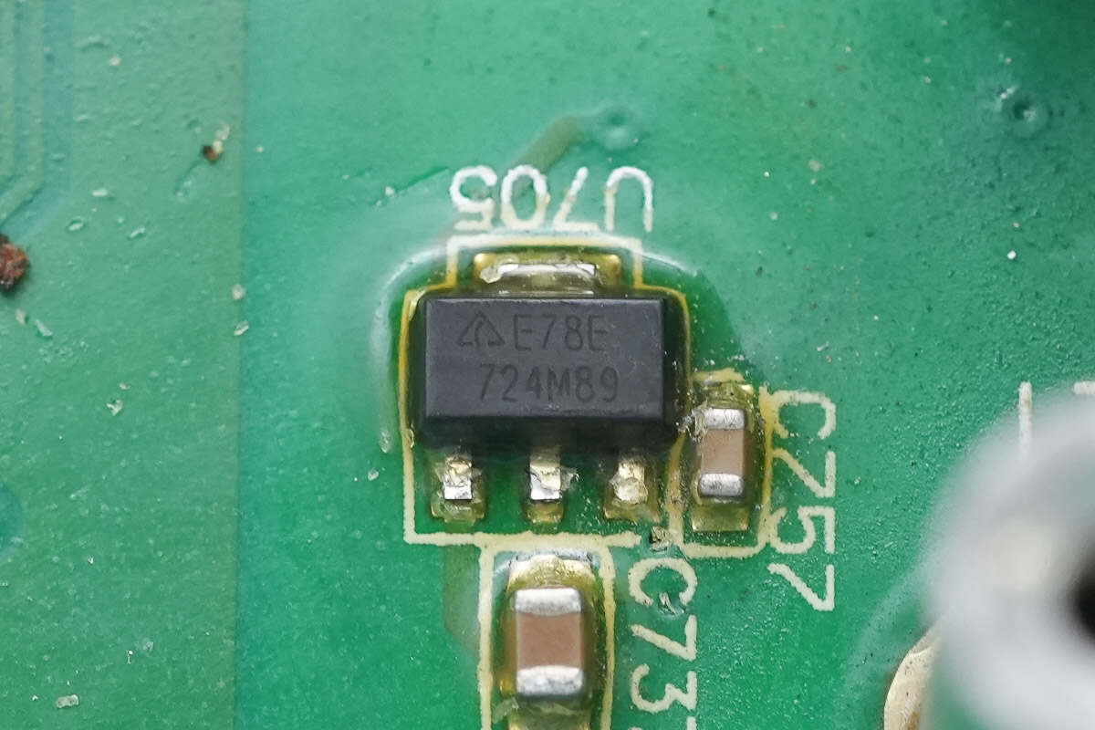
The voltage regulator chips are from DIODES, marked with E78E, model AS78L05. They provide an output voltage of 5V and come in an SOT-89 package.
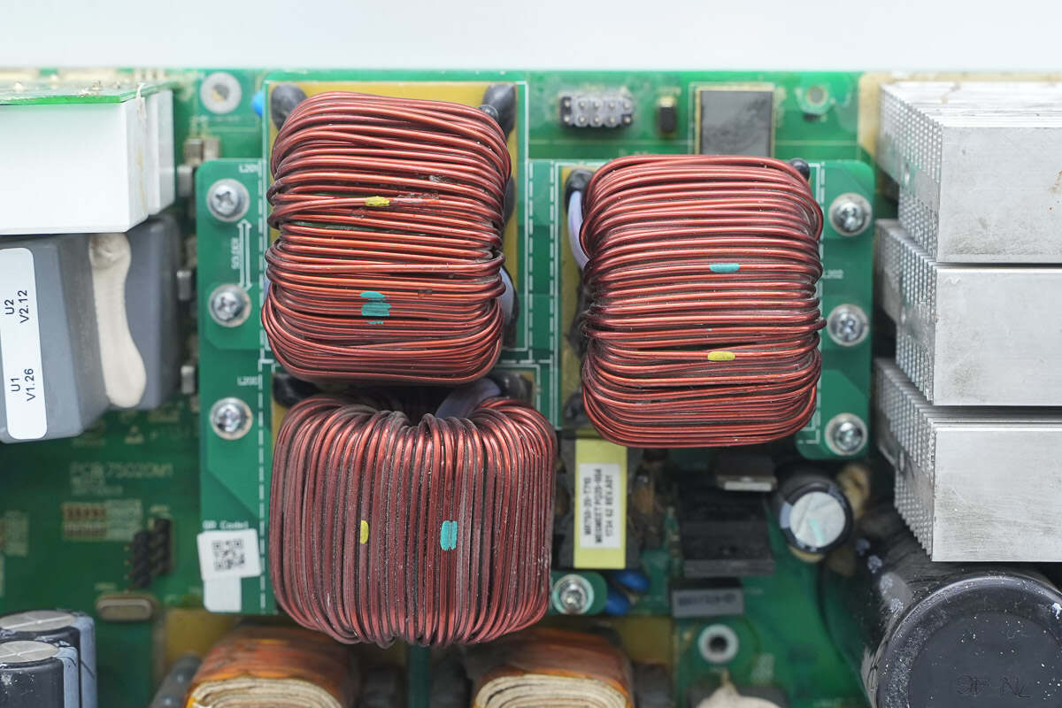
The PFC boost inductors are soldered on a small PCB and secured with screws.
The PFC boost inductors are connected via terminal posts.
The PFC boost inductors are soldered onto a small PCB.

The back of the small PCB has no components.
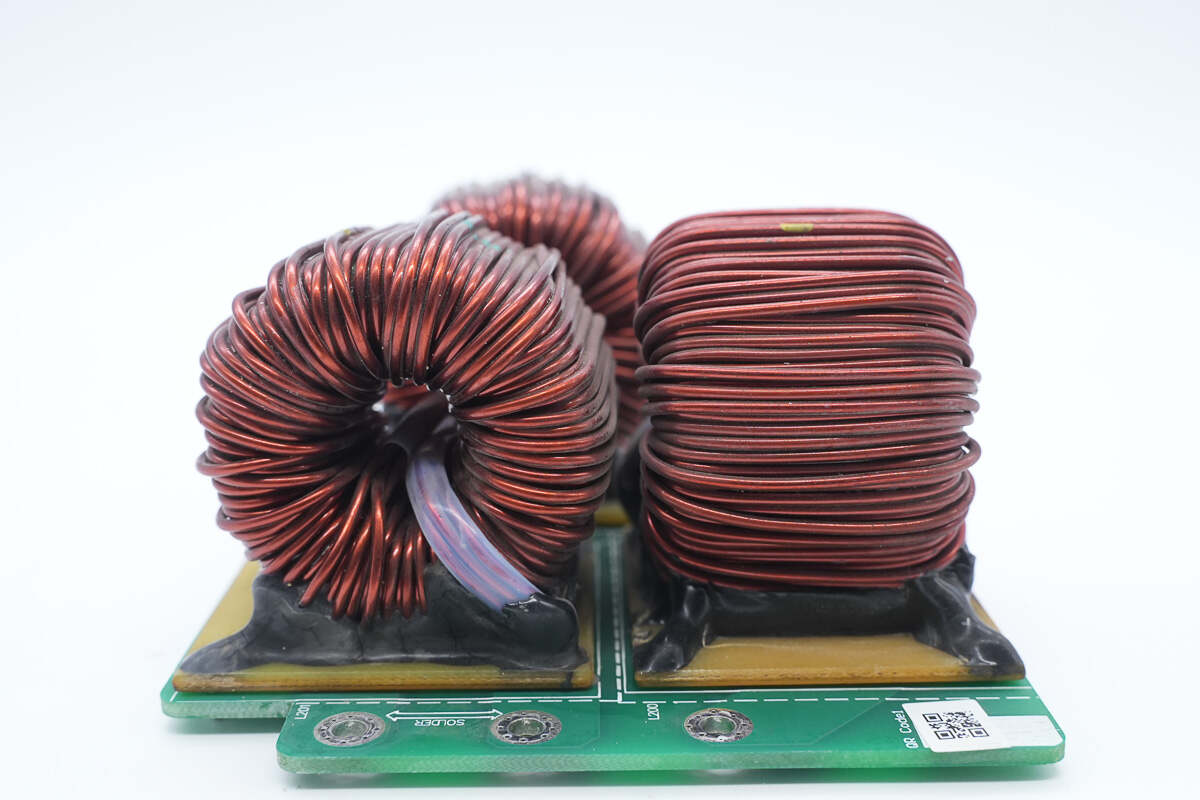
The PFC inductors are insulated with bakelite.

The PFC controller is from TI, model TMS320F28033. It features a built-in C2000 32-bit MCU with a clock speed of 60 MHz, 64KB of flash memory, and 20KB of RAM. It comes in a TQFP64 package.
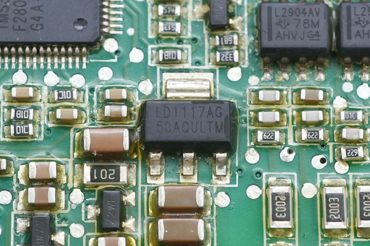
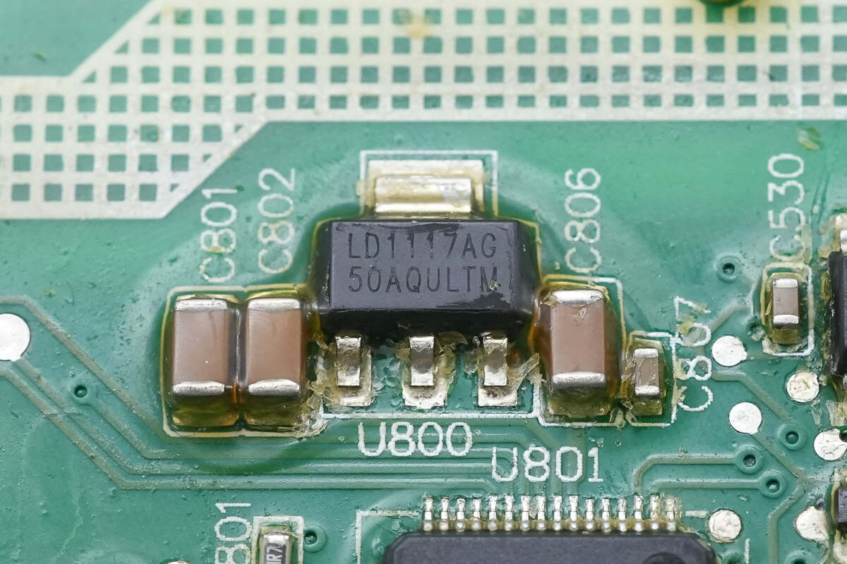
A close-up of the 1117 voltage regulator chip, with a 5V output.
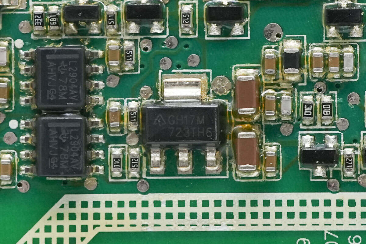
Another voltage regulator chip is from DIODES, marked with GH17M, model AZ1117H-3.3TRG1. It has an output voltage of 3.3V, an output current of 1A, and comes in an SOT-223 package.

An SMD LED is used for operation indication.

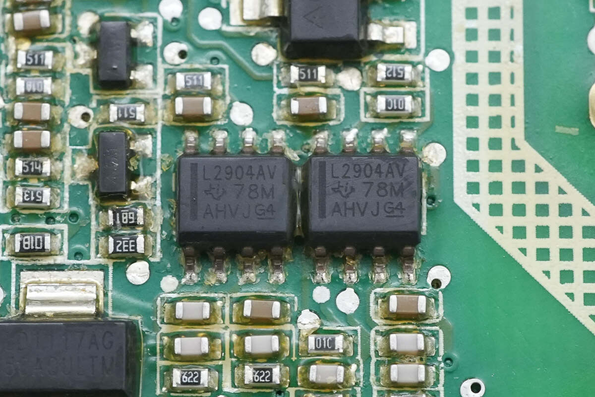
A close-up of the TI LM2904AV dual operational amplifier.
The other side of the PCBA module also has two LM2904AV dual operational amplifiers.
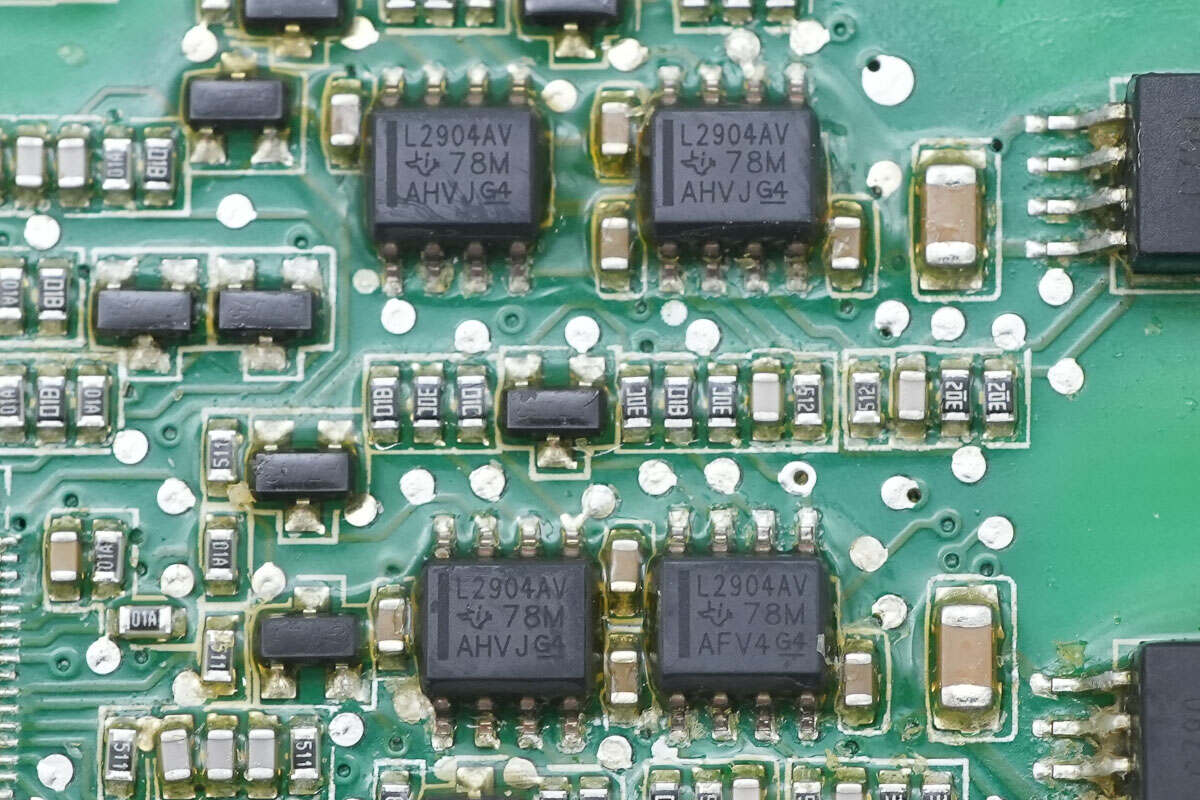
These four LM2904AV dual operational amplifiers are used for current signal amplification.
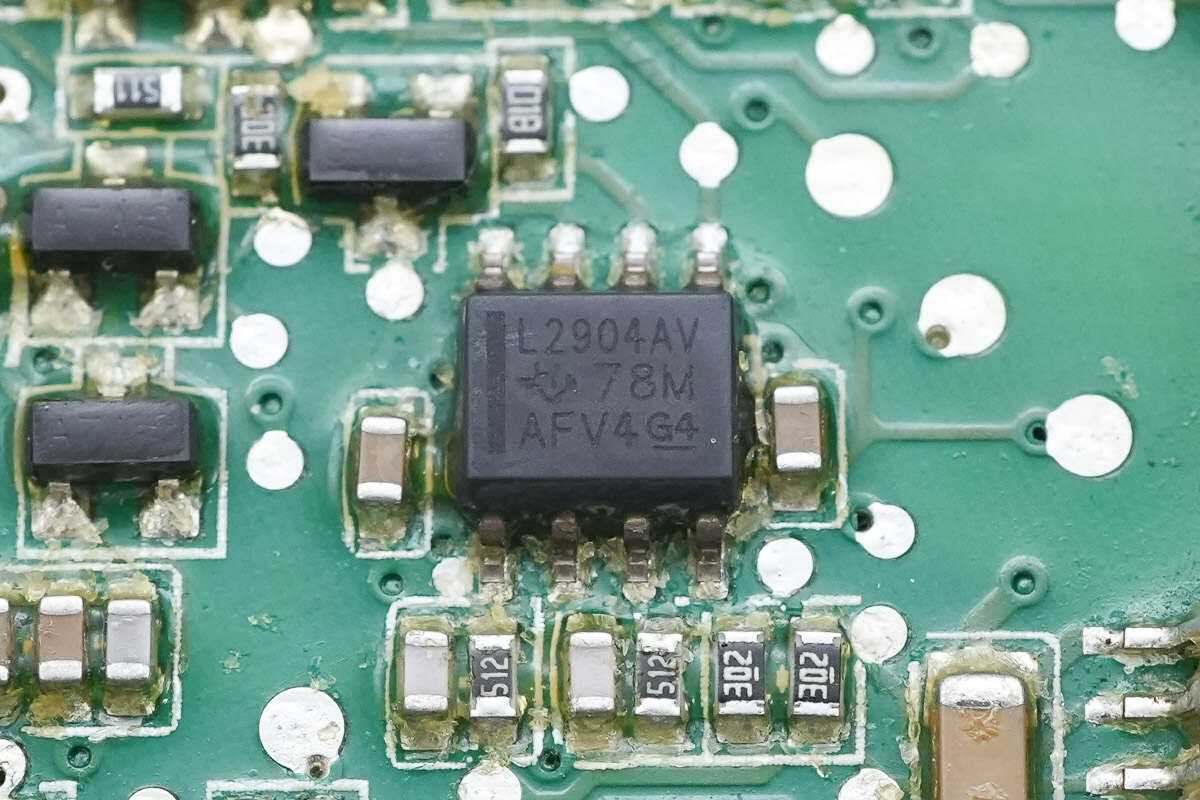
A close-up of the LM2904AV dual operational amplifier.
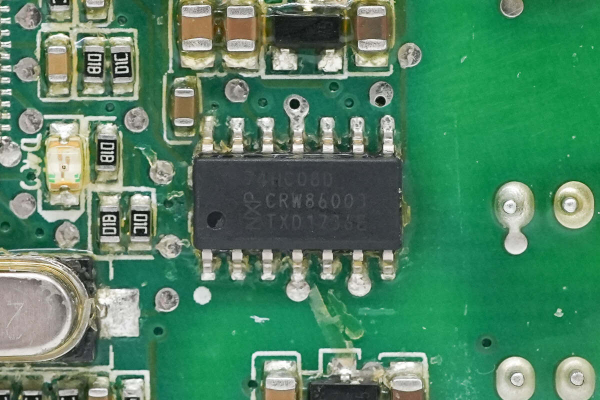
A close-up of the Nexperia 74HC08D AND gate chip. It is a quad 2-input AND gate and comes in an SOIC-14 package.
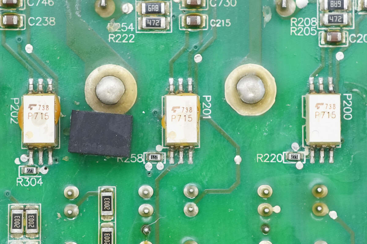
The Toshiba TLP715 optocoupler is used for isolating the PFC MOSFET driver signals and comes in an SOP6 package.
There are six drivers corresponding to the twelve PFC MOSFETs.
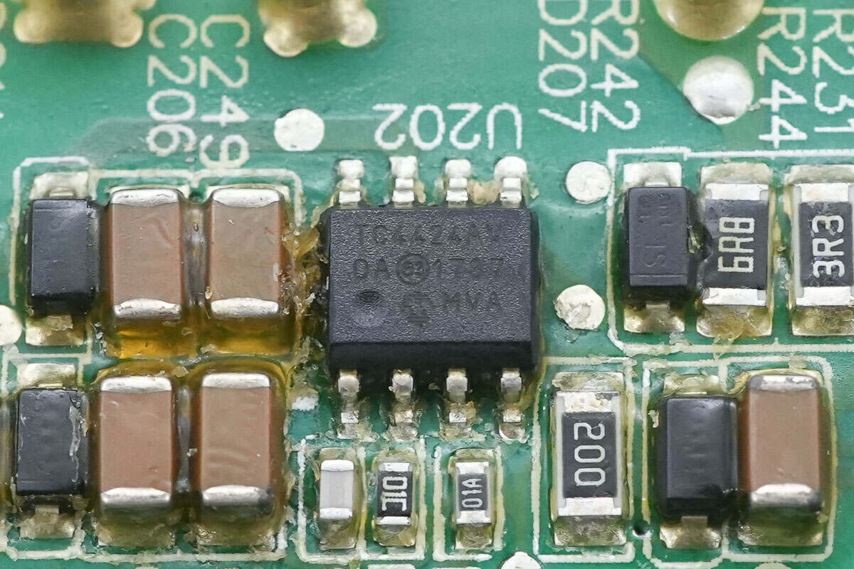
The driver is from Microchip, model TC4424A. It is a dual 3A driver, supporting CMOS and TTL input levels, and comes in an SOIC8 package.
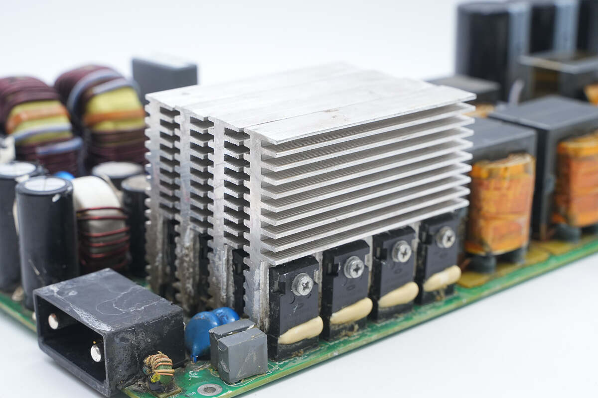
There are PFC MOSFETs and rectifiers on three heat sinks.
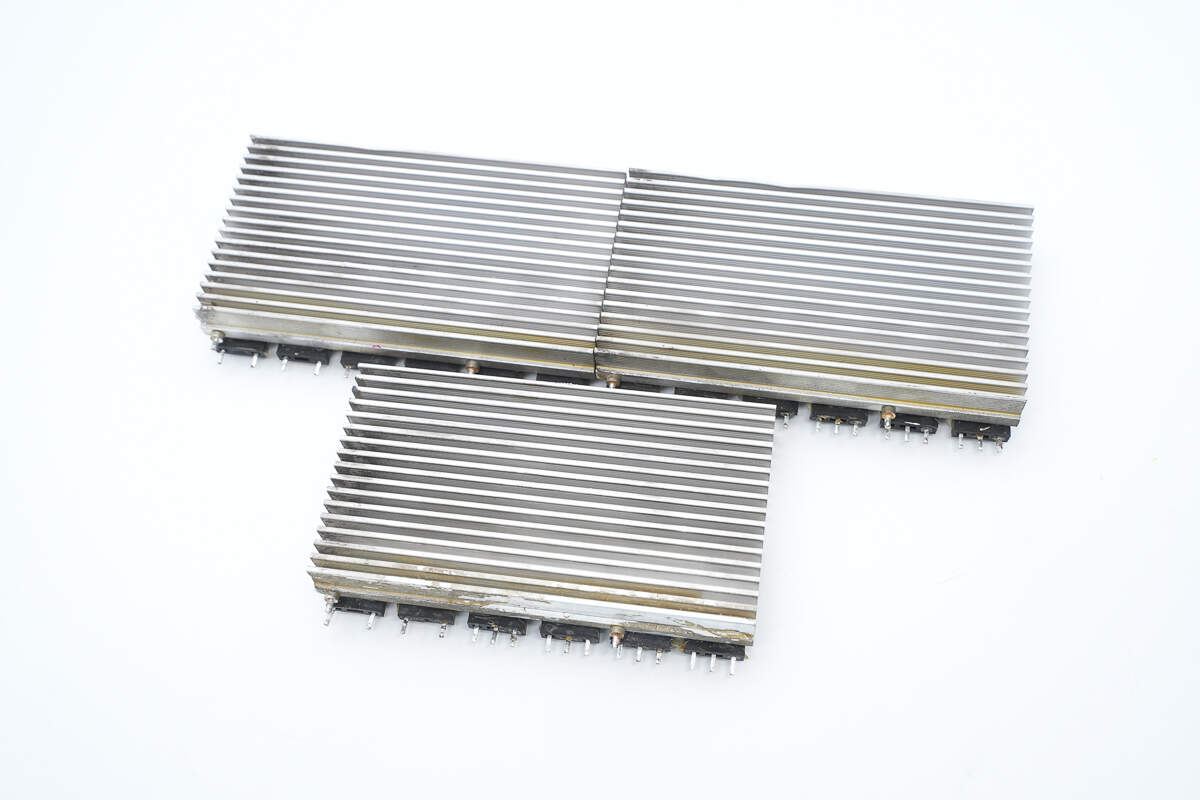
The back of the heat sinks has grooves.
On the lower left side, there are four PFC MOSFETs, and on the right side, there are two PFC rectifiers.

The PFC MOSFETs are from Toshiba, model TK62N60W5. They are NMOS type, with a voltage rating of 600V, an Rds(on) of 36mΩ, and are packaged in a TO-247 package.
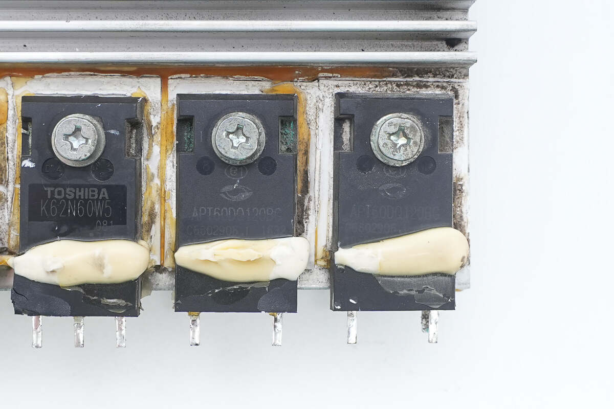
The PFC rectifiers are from Microchip, model APT60DQ120BG. They are ultra-fast soft recovery diodes with a rating of 1200V, 60A, and come in a TO-247 package.
There are electrolytic capacitors in two sets of heat sinks.

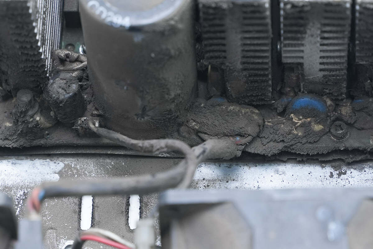
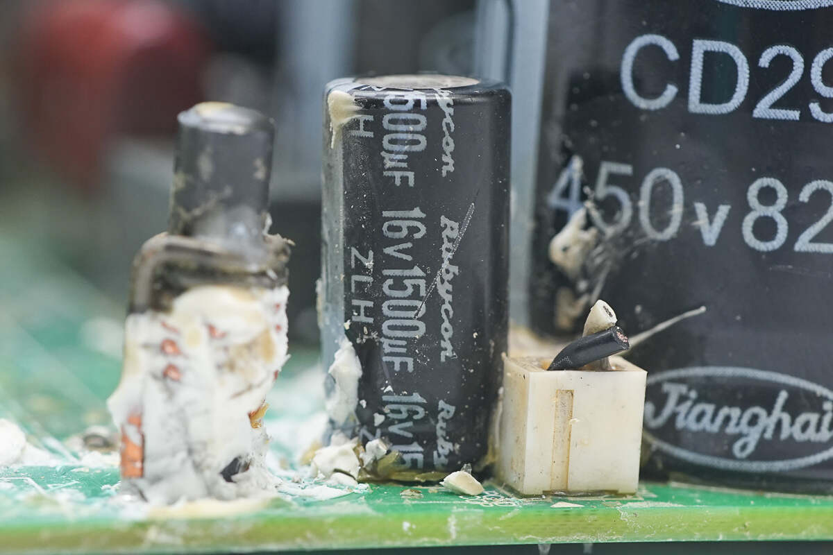
The electrolytic capacitors are from Jianghai, part of the CD294 series. They are rated at 450V, 820μF, and are connected in a 2 parallel and 2 series configuration, resulting in an equivalent rating of 900V, 820μF.
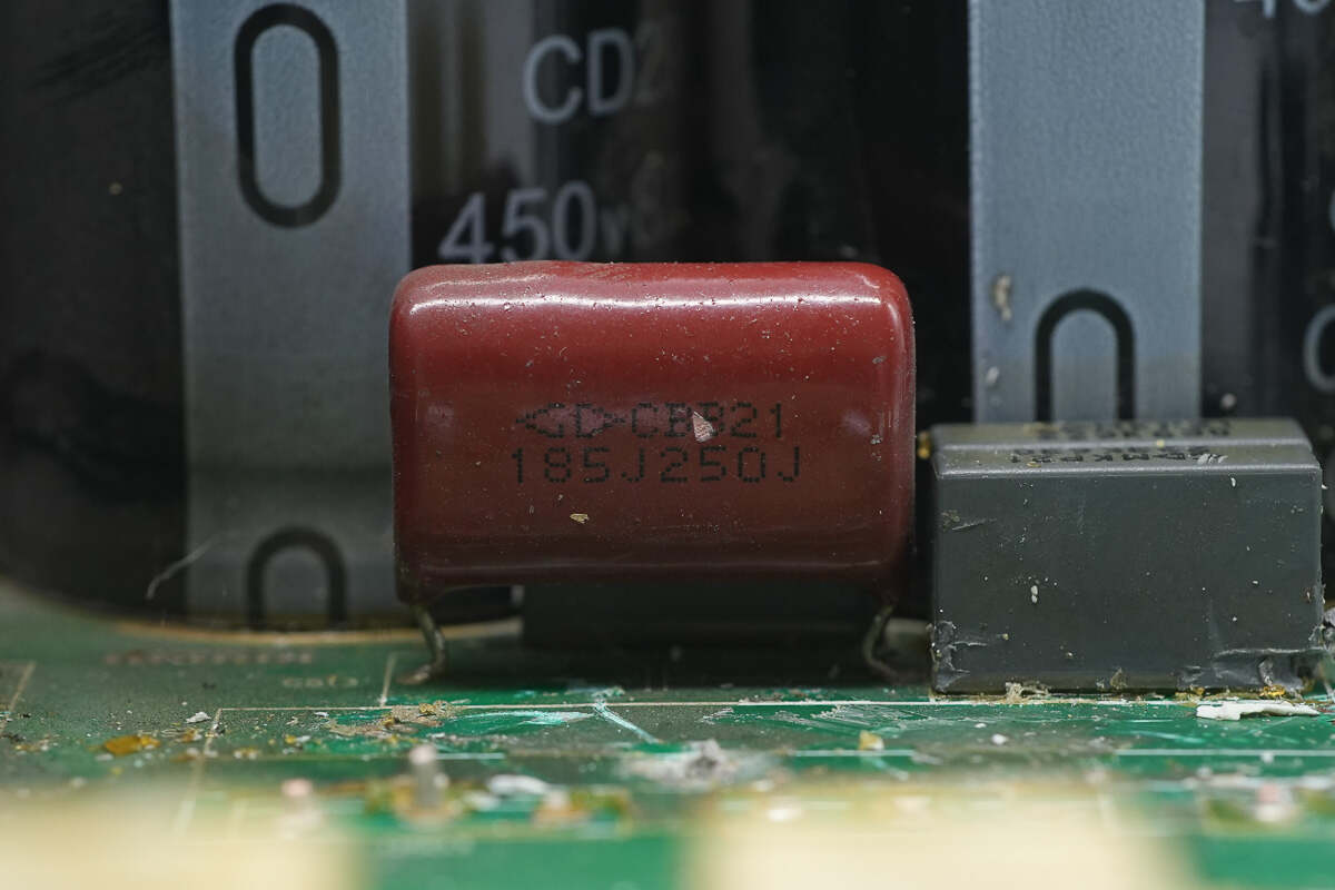
The film capacitor is rated at 1.8μF, 250V.
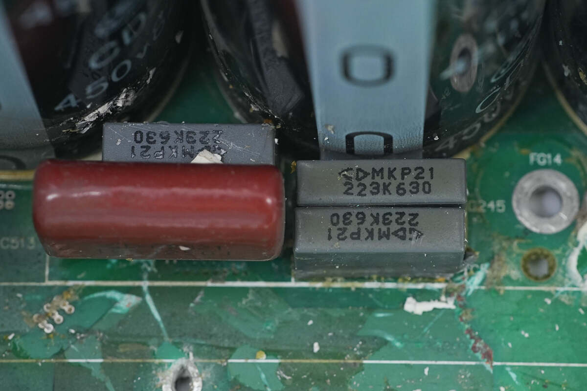
The other three film capacitors are rated at 0.022μF, 630V.
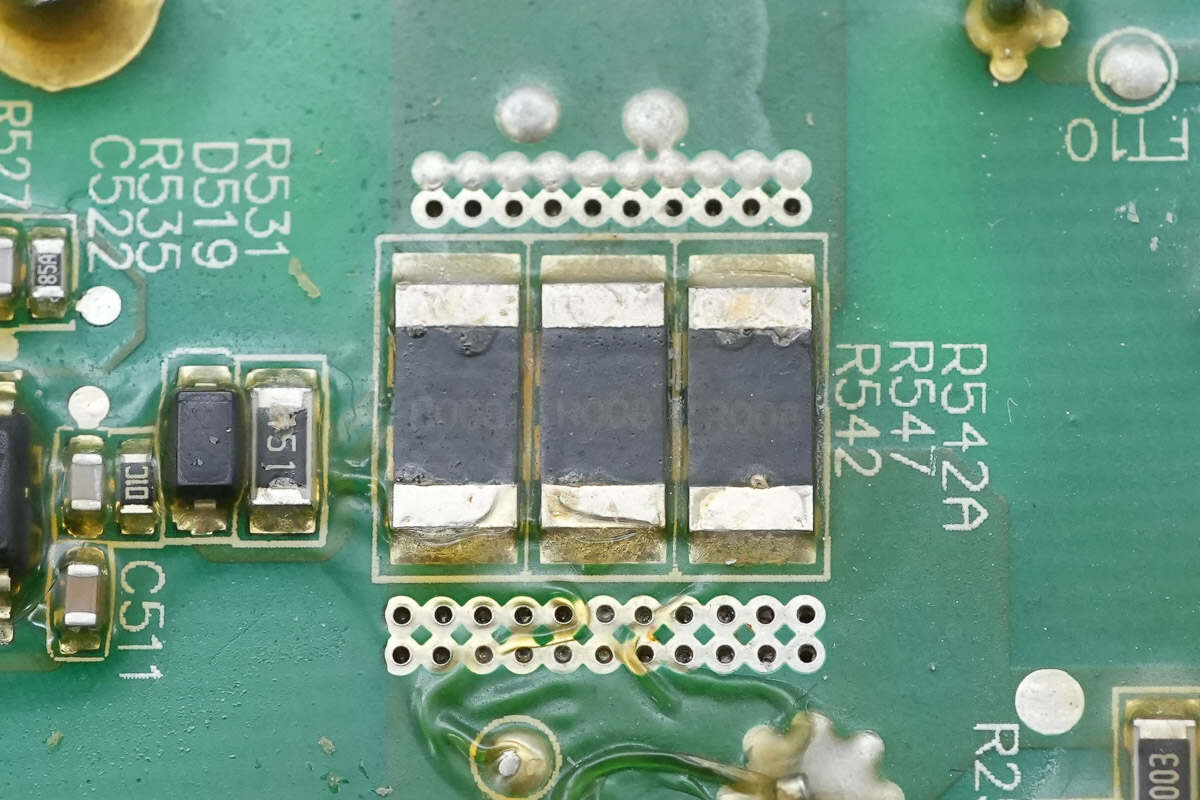
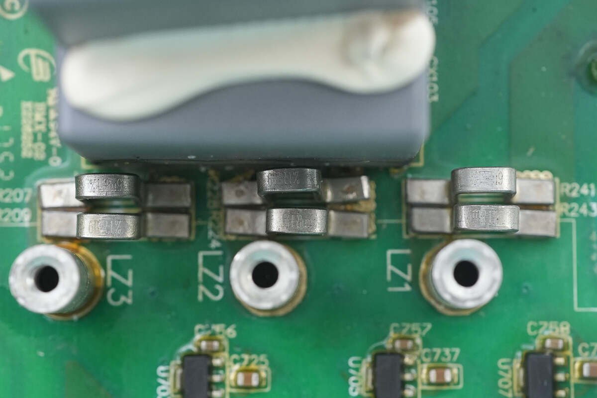
The three current sensing resistors are connected in parallel and are used for current detection in the full-bridge LLC power stage.
A close-up of the LM393 dual voltage comparator.
The LLC controller is equipped with a metal shielding cover.
After removing the shielding cover, the LLC controller is located inside.
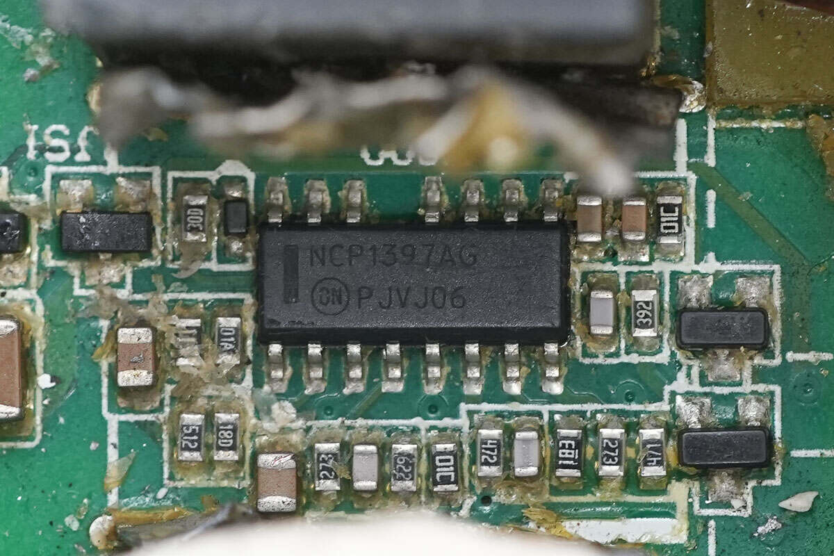
The LLC controller is from Onsemi, model NCP1397A. The chip features a built-in 600V gate driver, supports a switching frequency range of 50-500kHz, and comes in an SO-16 package.
The back of the LLC controller has a shielding plate.
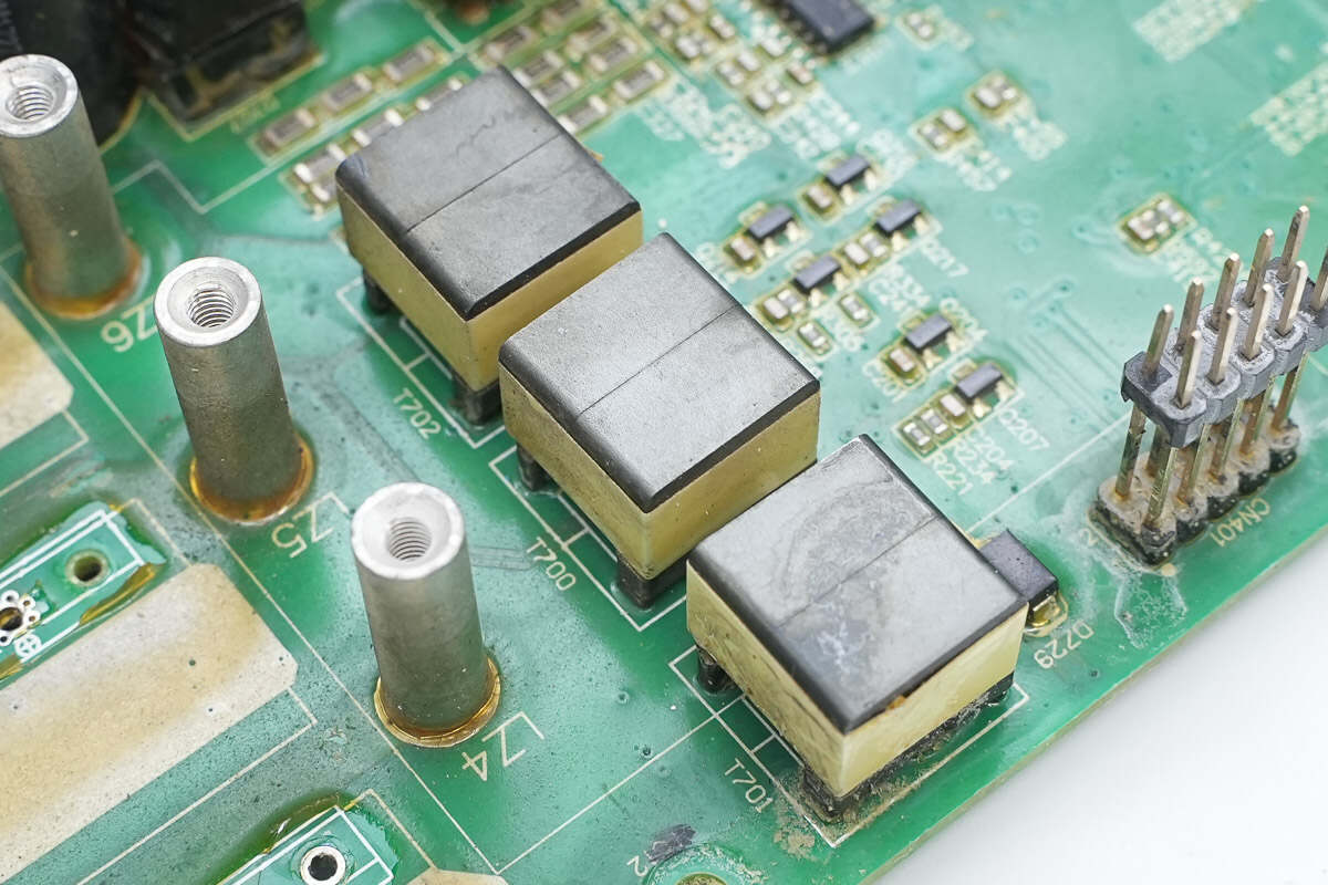
The four drivers are used to drive the isolated transformer.
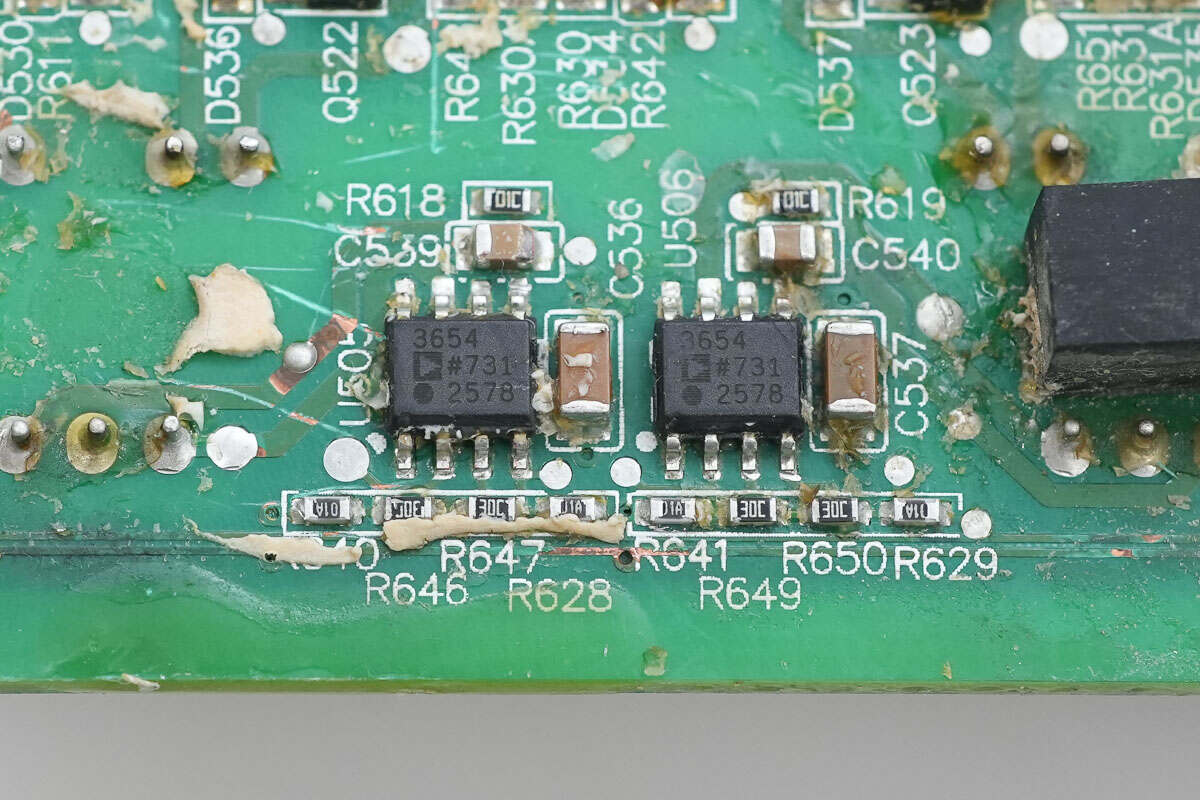
The drivers are from ADI, model ADP3654. They are dual-channel, high-speed low-side drivers, supporting 4A output current, and come in an SOIC-8-EP package.
The four drivers for the transformer correspond to two sets of full-bridge MOSFETs.
The drive transformers are insulated with tape.
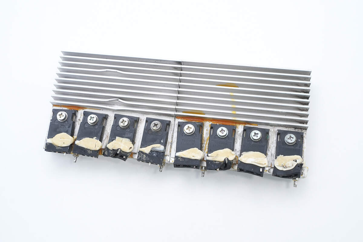
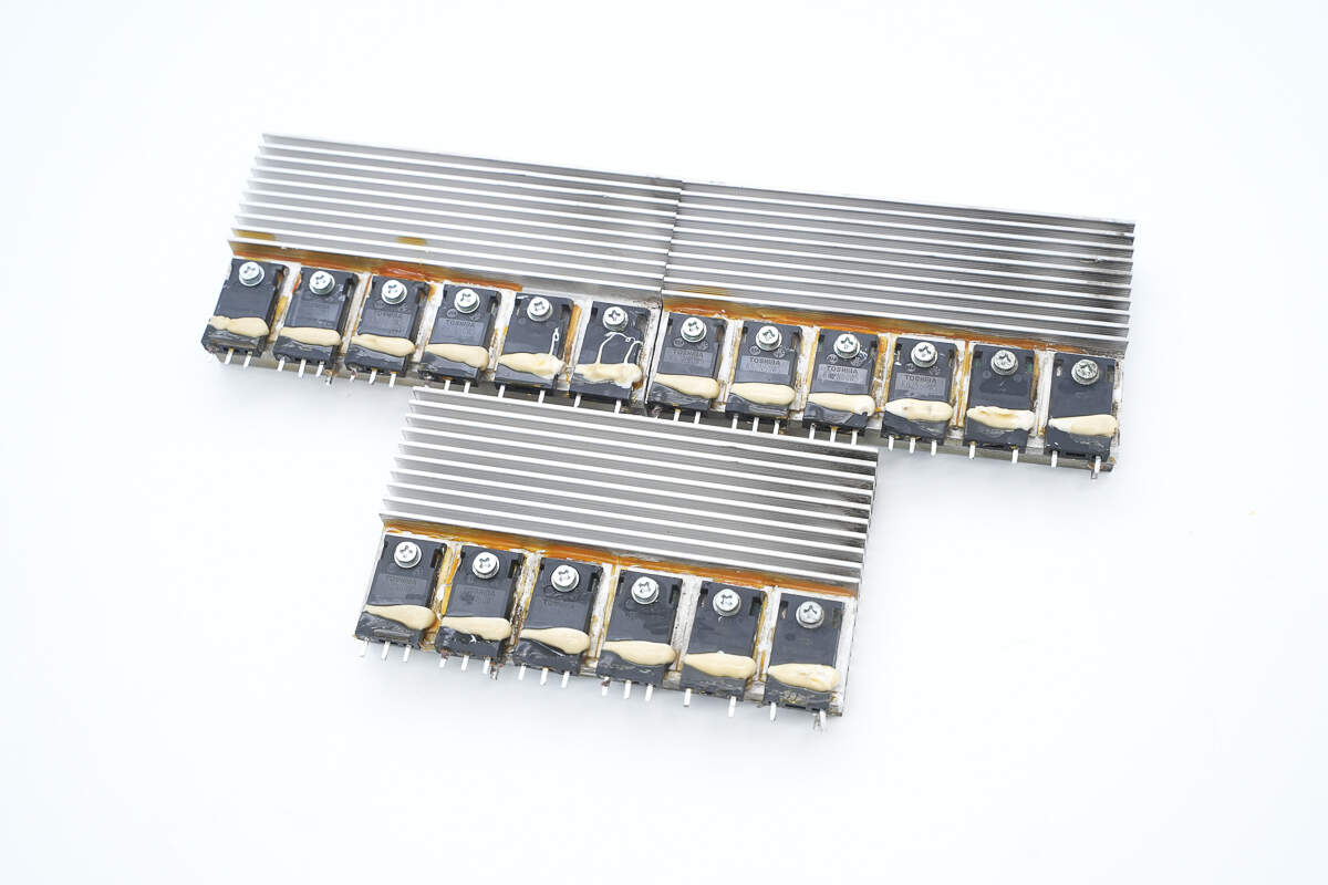
After removing the heat sinks, each of the two heat sinks has four LLC MOSFETs.
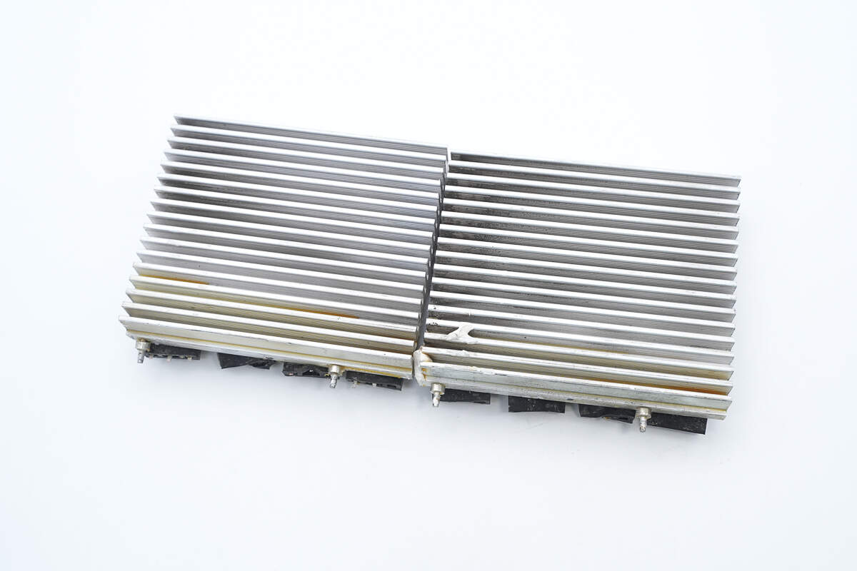
The back of the heat sinks also has a grooved design.

The LLC MOSFETs are from Toshiba, model TK62N60W5, which is the same as the PFC MOSFET model.
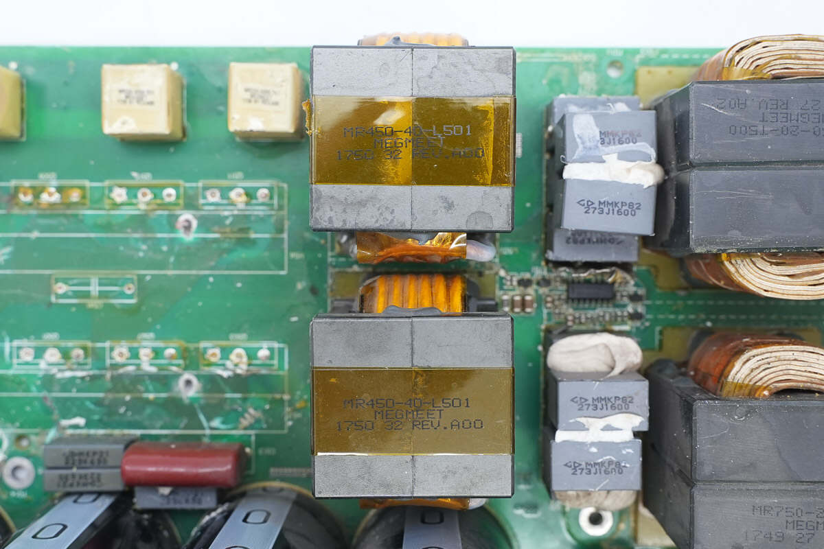
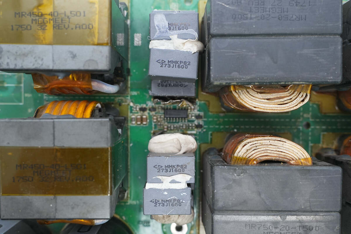
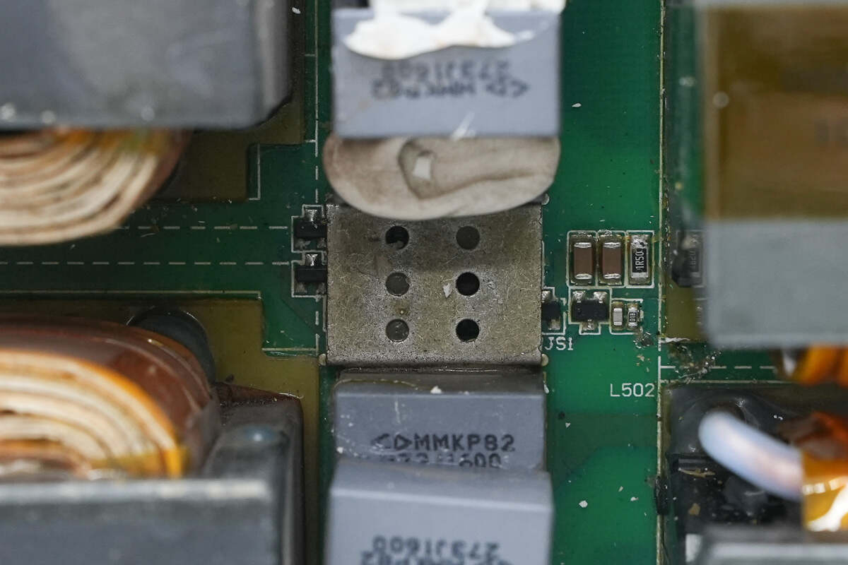
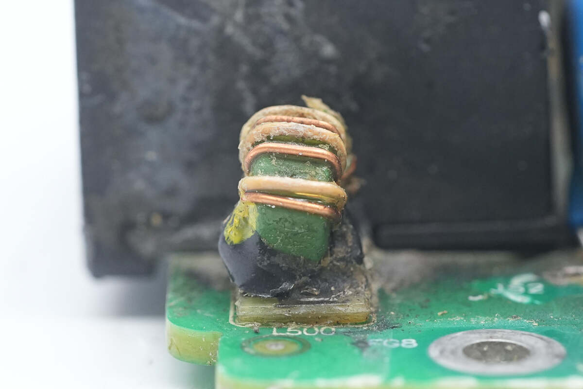
The resonant inductor is wound with Litz wire and is insulated at the bottom with bakelite.

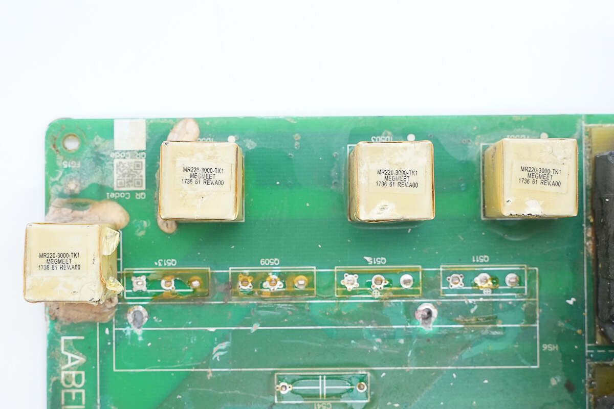
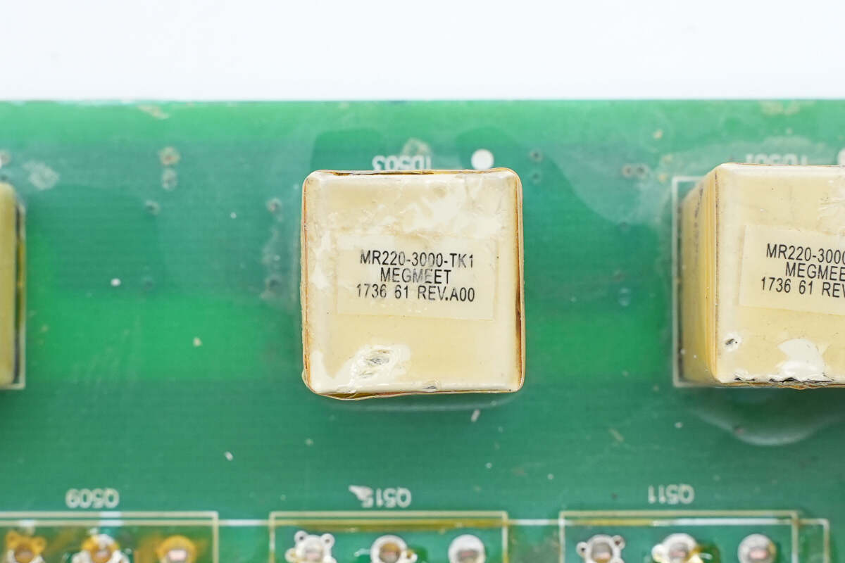
The resonant capacitors are from Faratronic, with a specification of 0.027μF, 1600V, and five capacitors connected in parallel.
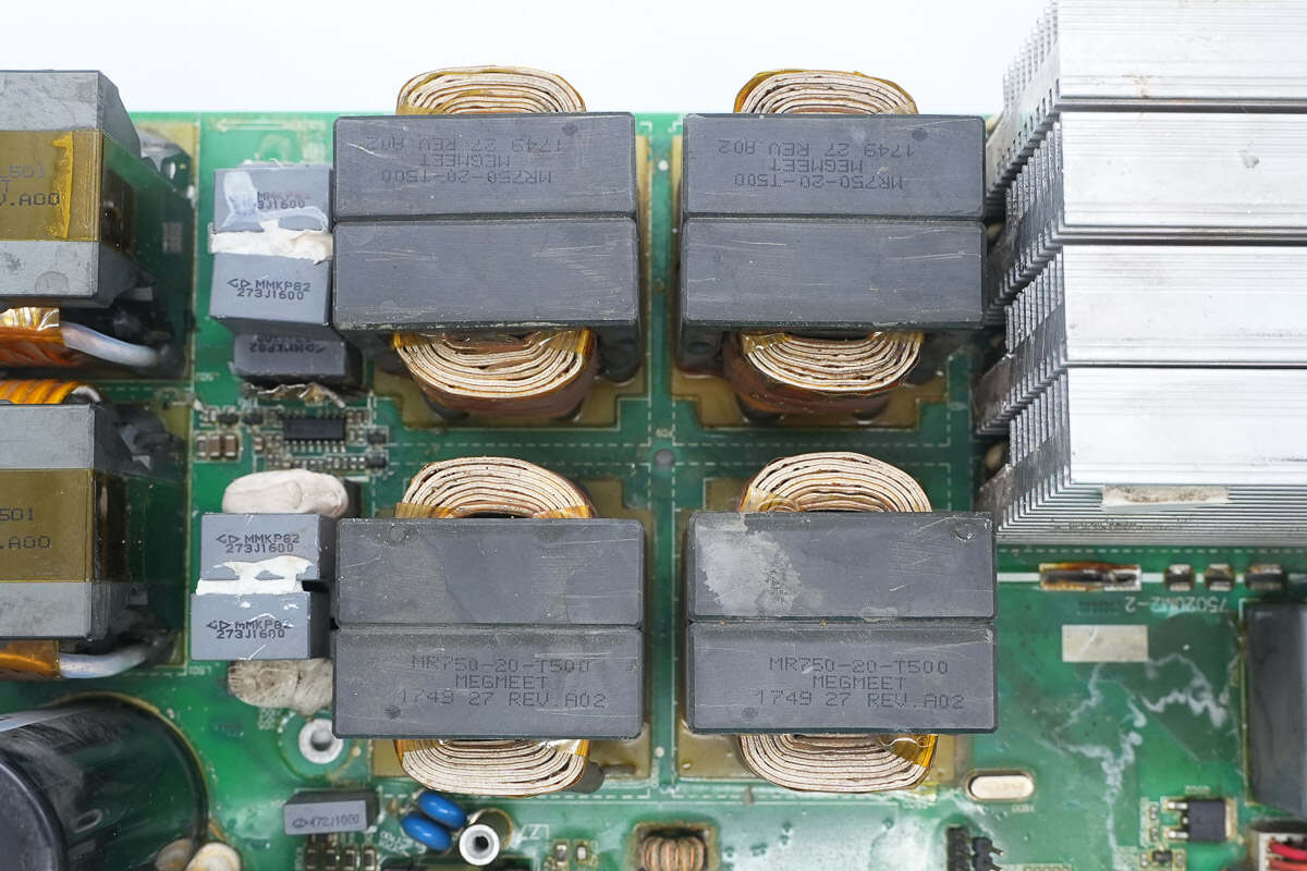
The four transformers have bakelite insulation at the bottom.
The rectifiers are equipped with heat sinks.
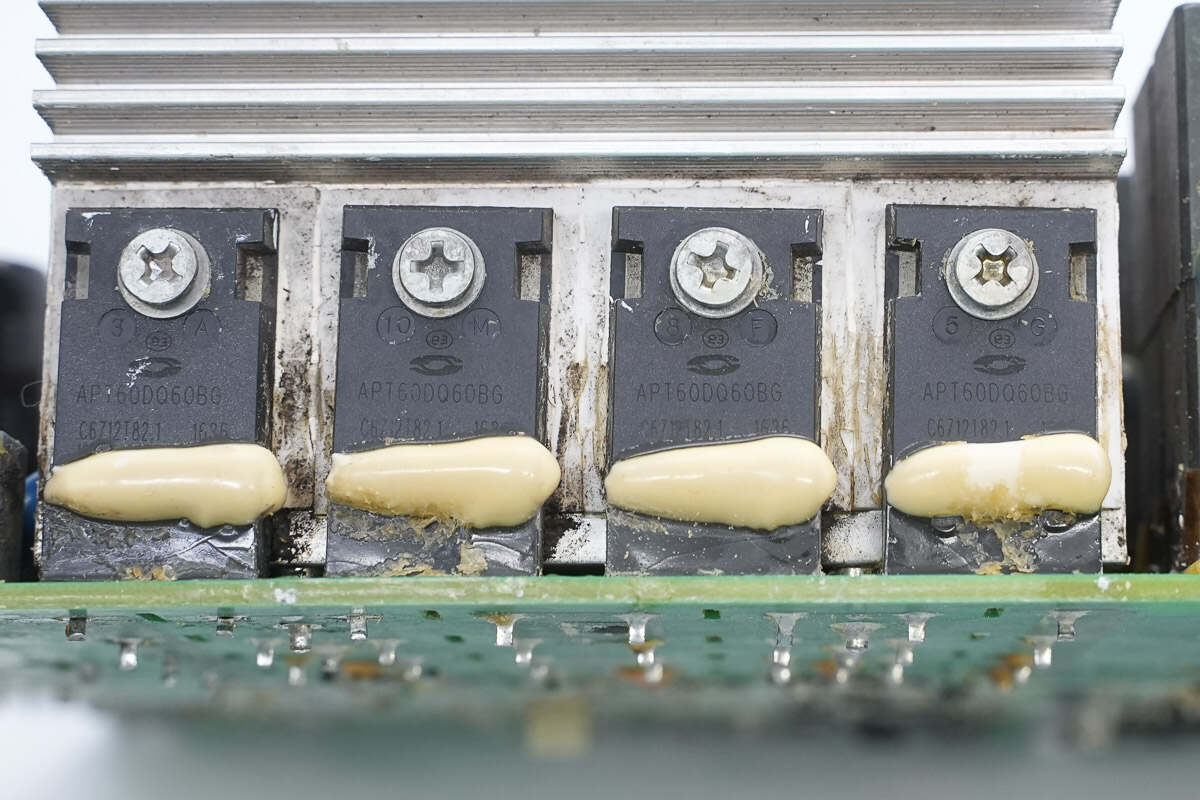
The rectifiers are from Microchip, model APT60DQ60BG. They are ultra-fast soft recovery diodes with a rating of 600V, 60A, and come in a TO247 package.
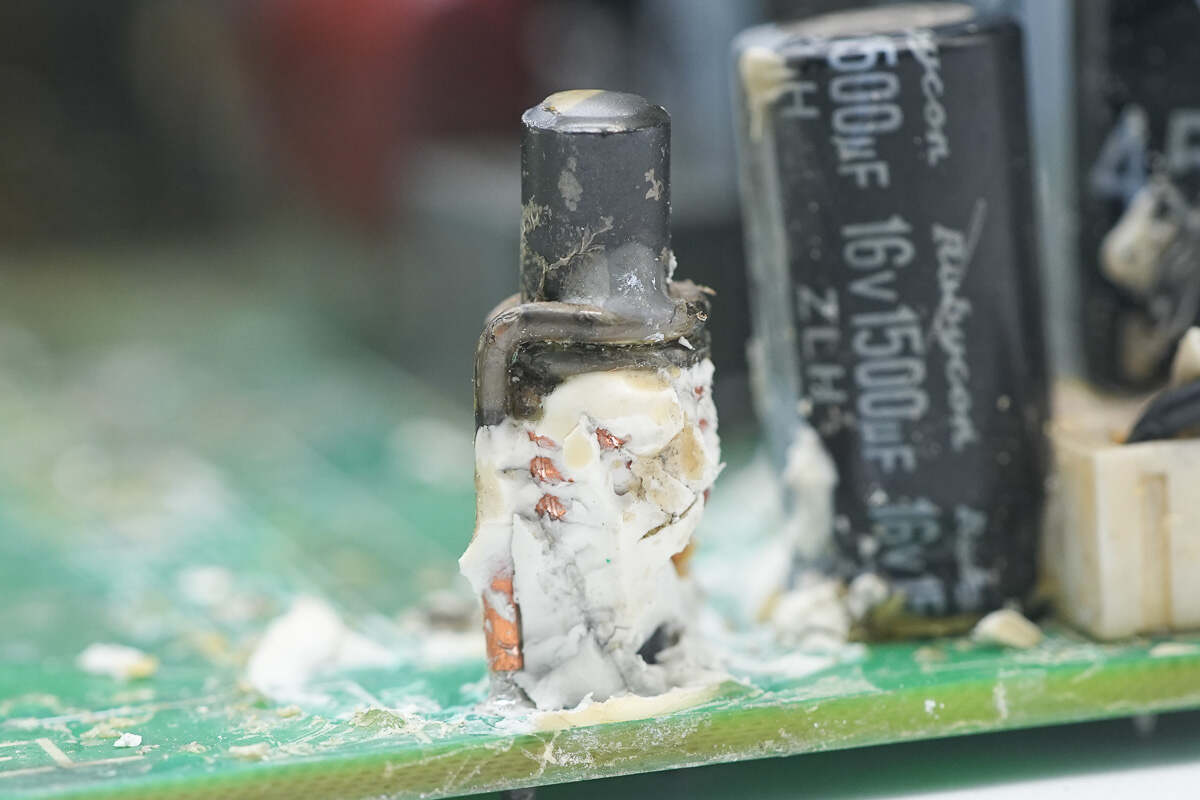
The solid capacitors and discharge resistors are soldered onto a vertical PCB.

The back of the small PCB has no components, and there is a Mylar sheet of insulation between it and the heat sink.
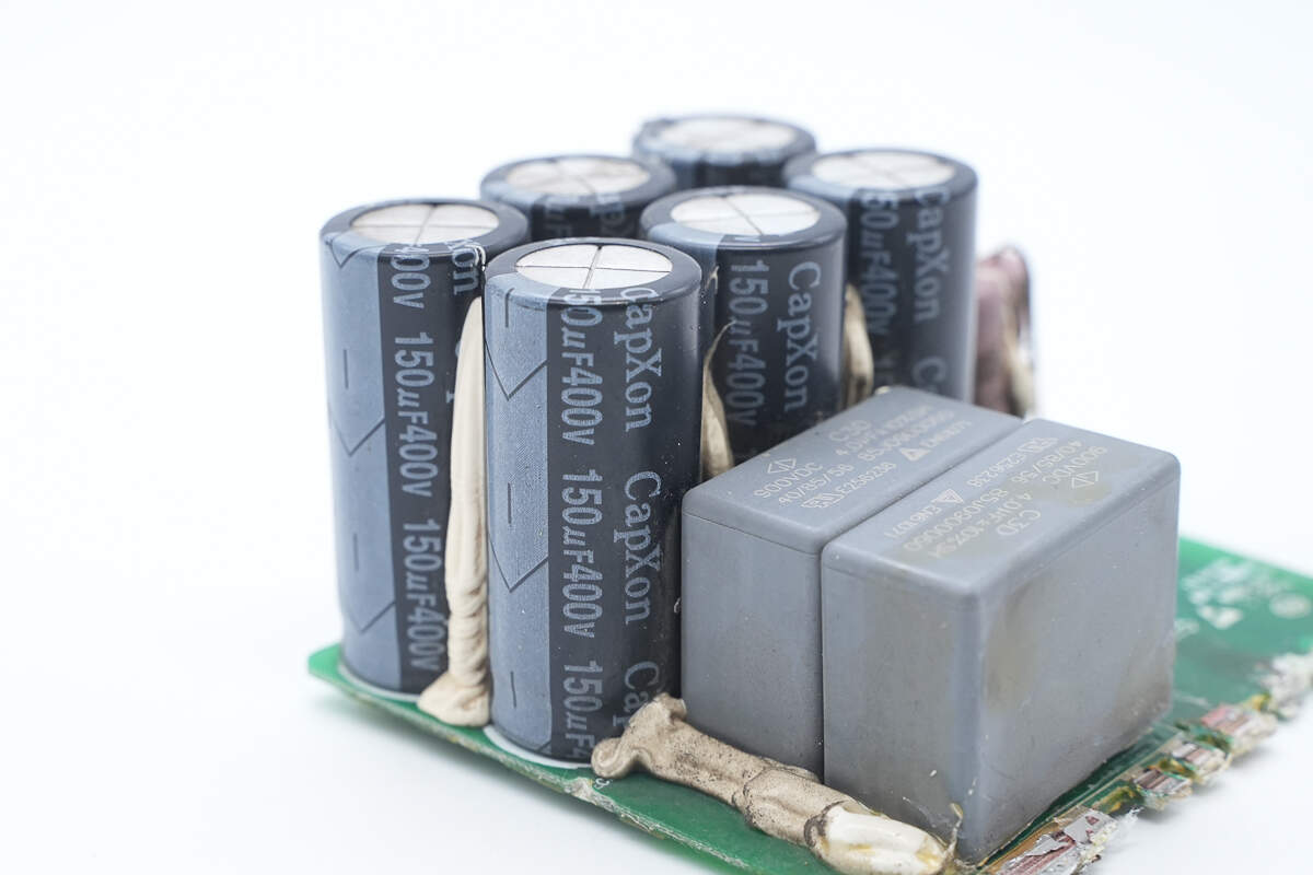
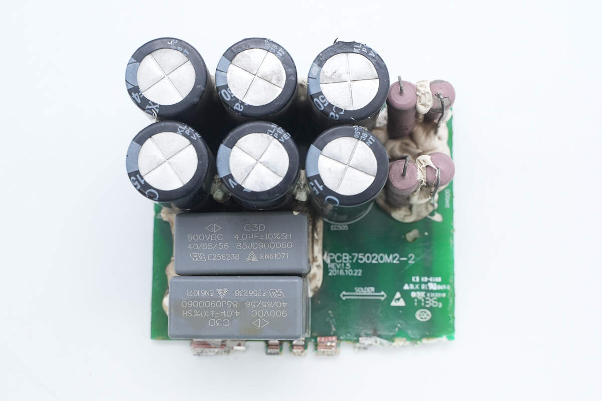
The filter capacitors are from CapXon, with a specification of 150μF, 400V, and a total of six capacitors.
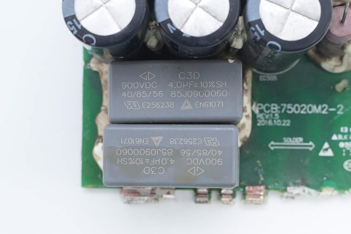
The film capacitors are from Faratronic, with a specification of 900V, 4μF, and are connected in parallel.
The four output discharge resistors are connected in series, with each resistor having a value of 160Ω.
Two 5mΩ current sensing resistors are used for output current detection.
The film capacitor is rated at 900V, 4μF.

The solid capacitors are from Rubycon, with a specification of 400V, 150μF.
A close-up of the filter inductor.
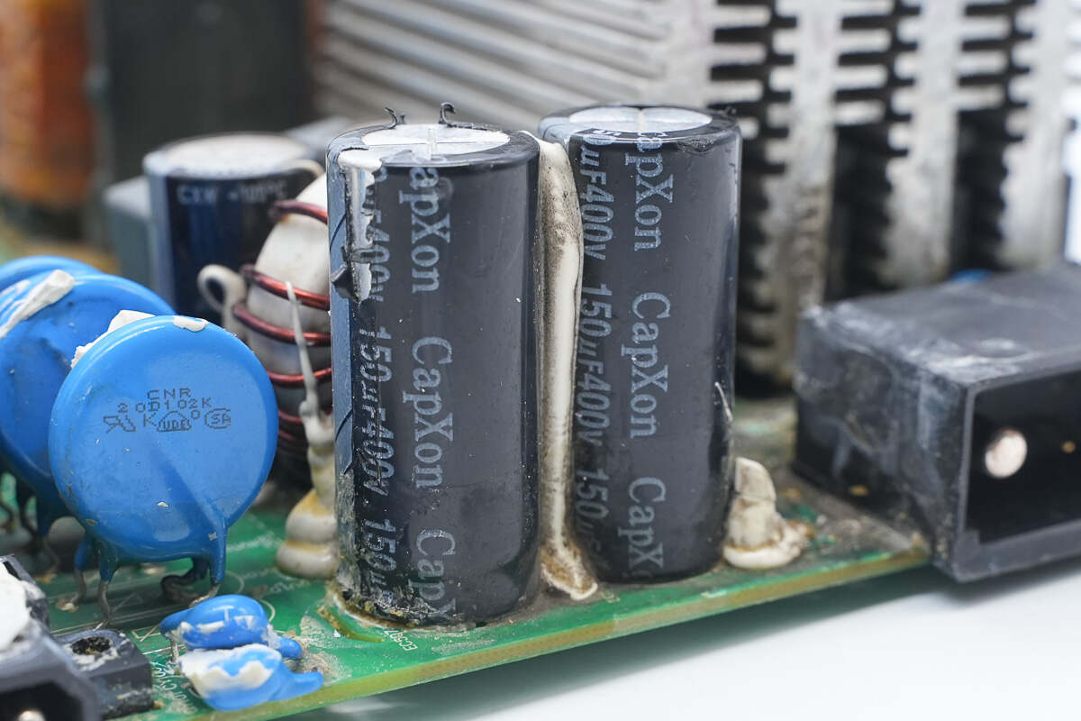
The solid capacitors are from CapXon, with a specification of 150μF, 400V.
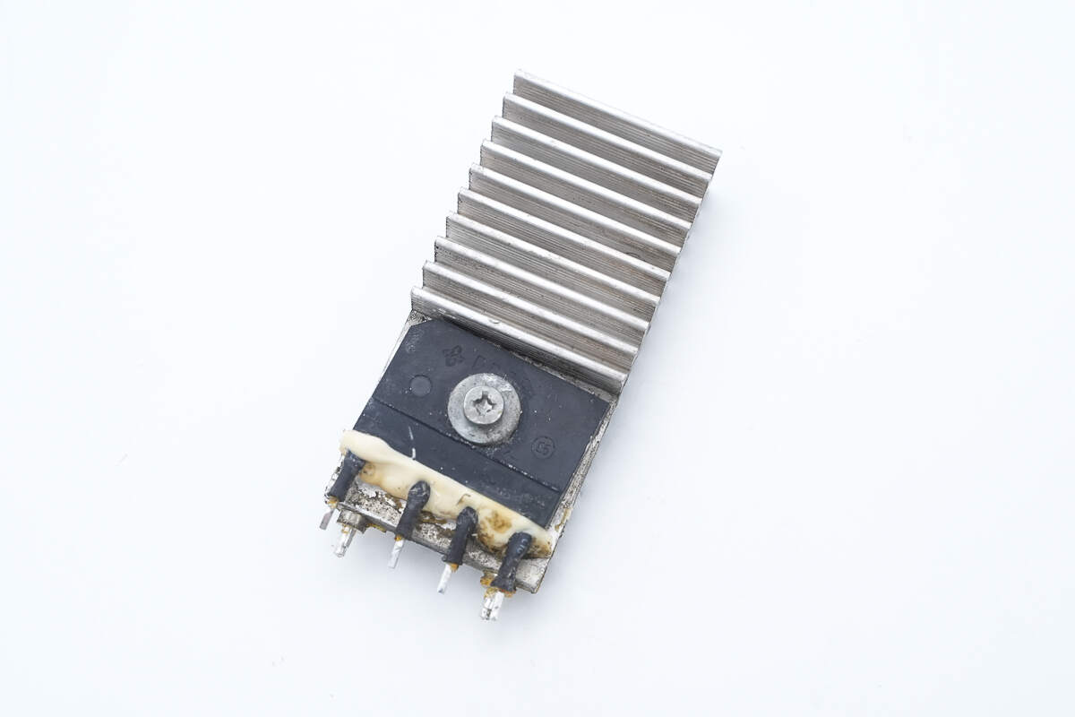
The output reverse polarity protection bridge rectifier is equipped with a heat sink.
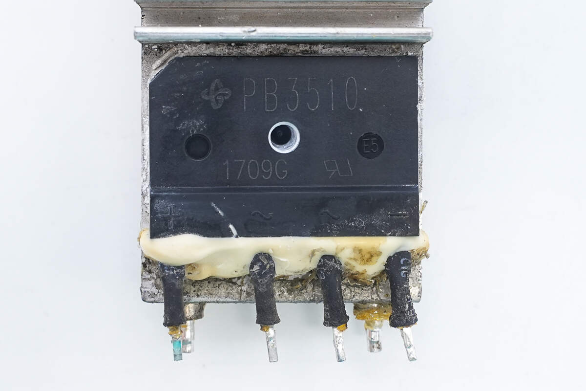
The bridge rectifier is from VISHAY, model PB3510. It is rated for 35A, 1000V, and comes in a PB package.
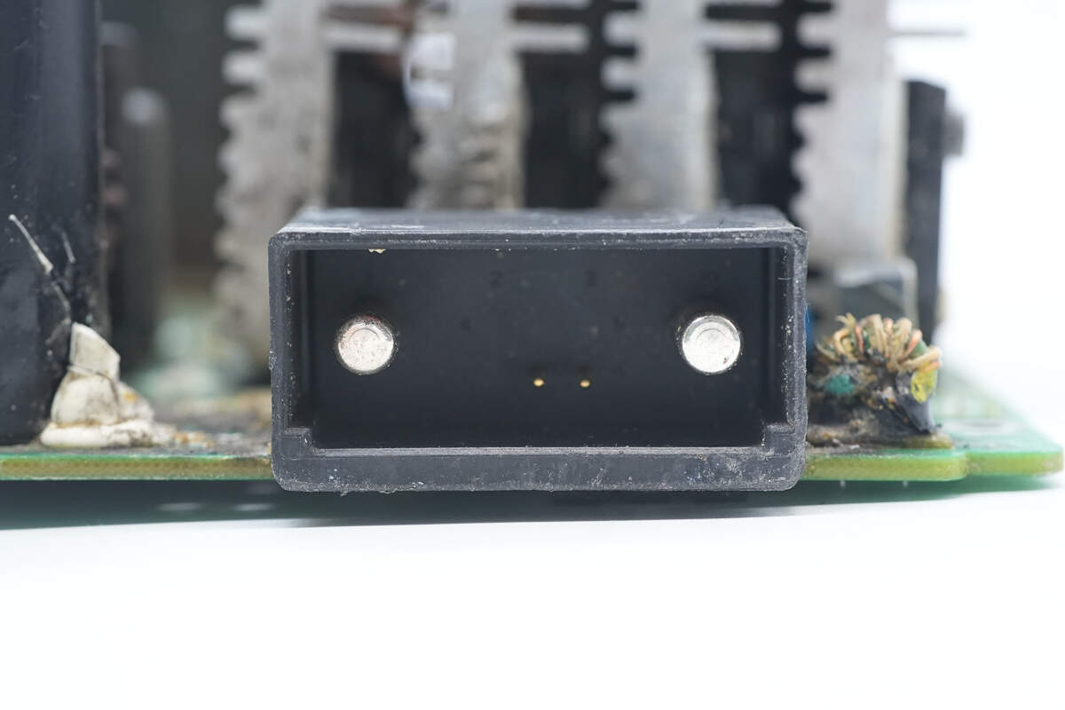
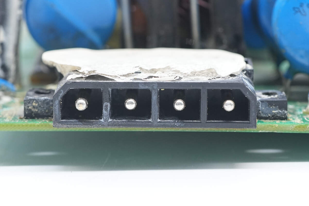
The DC output interface has thicker round pins on both sides for positive and negative output, with the thinner pins in the middle used for communication.
The communication line is equipped with a filter inductor.
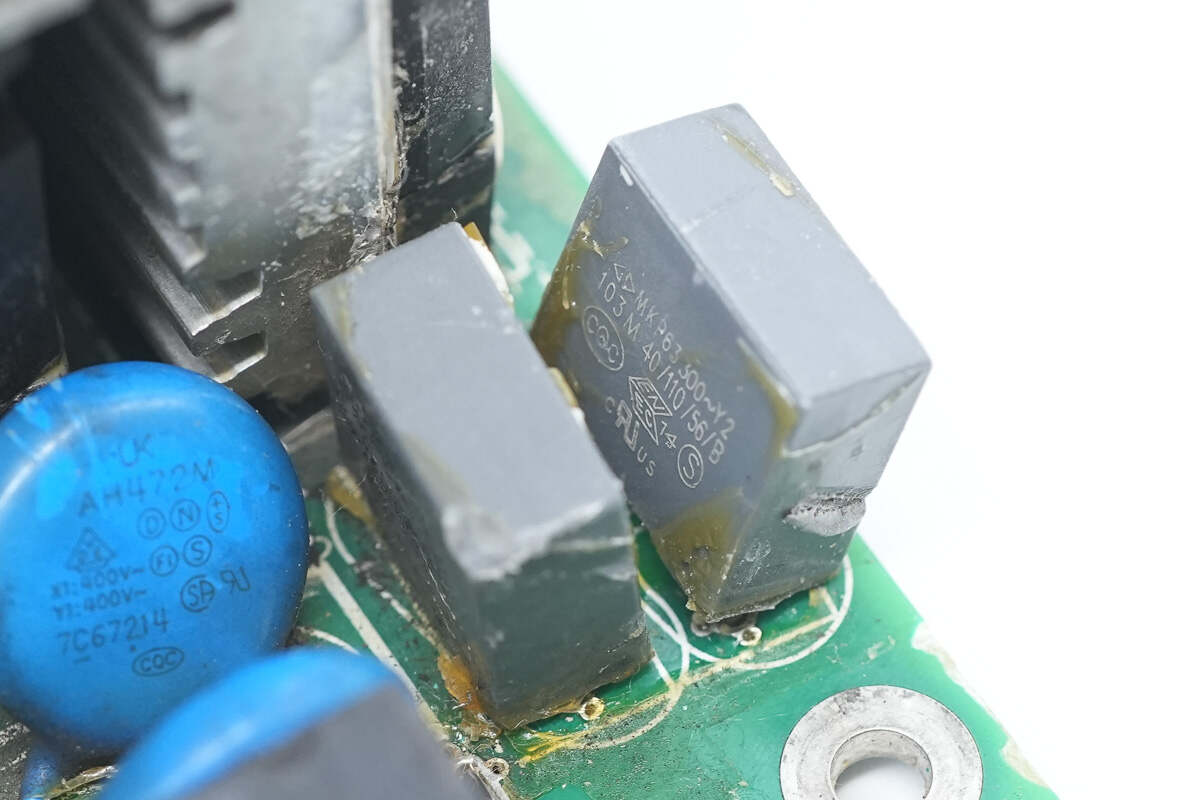
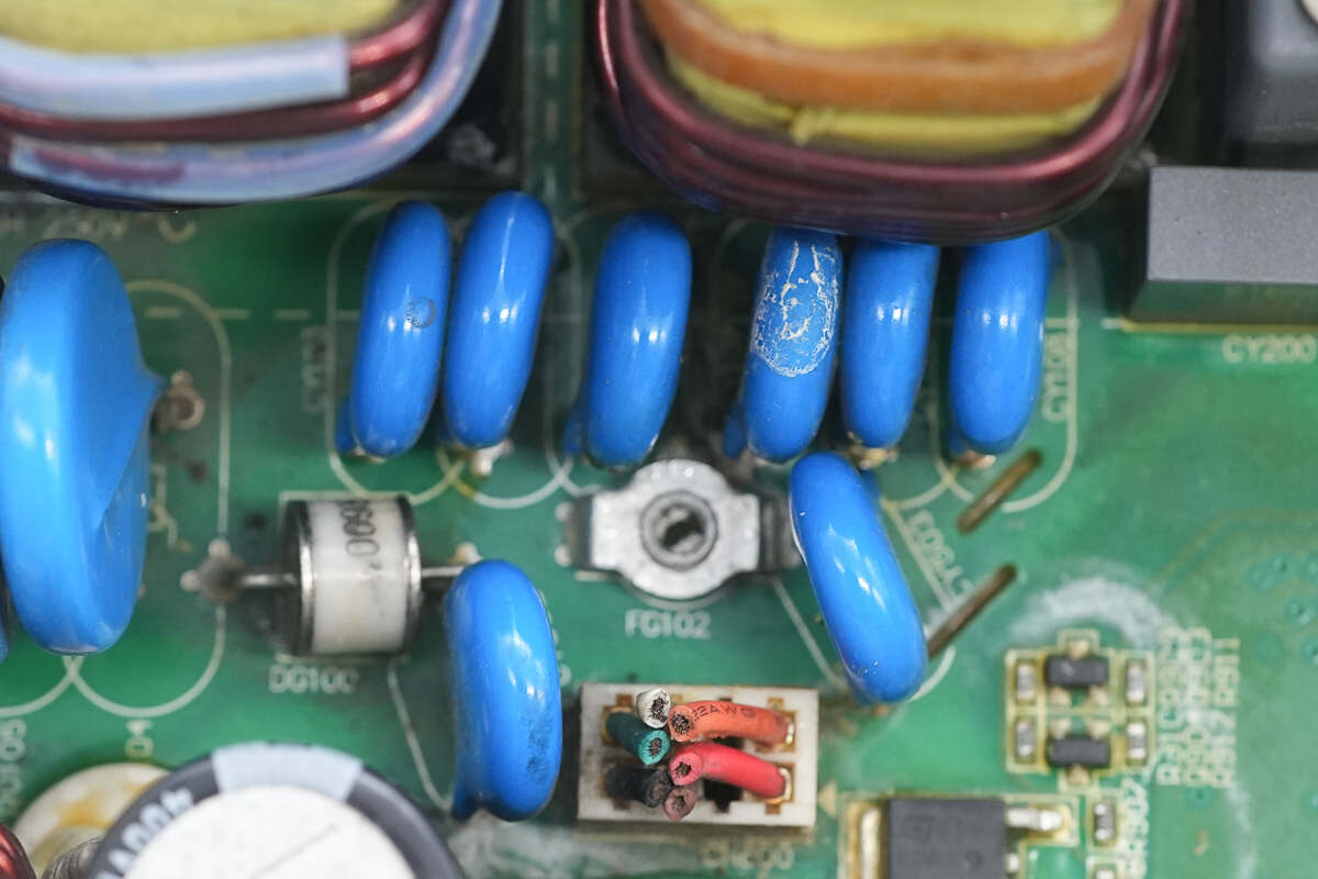
The film Y capacitors are from Faratronic.
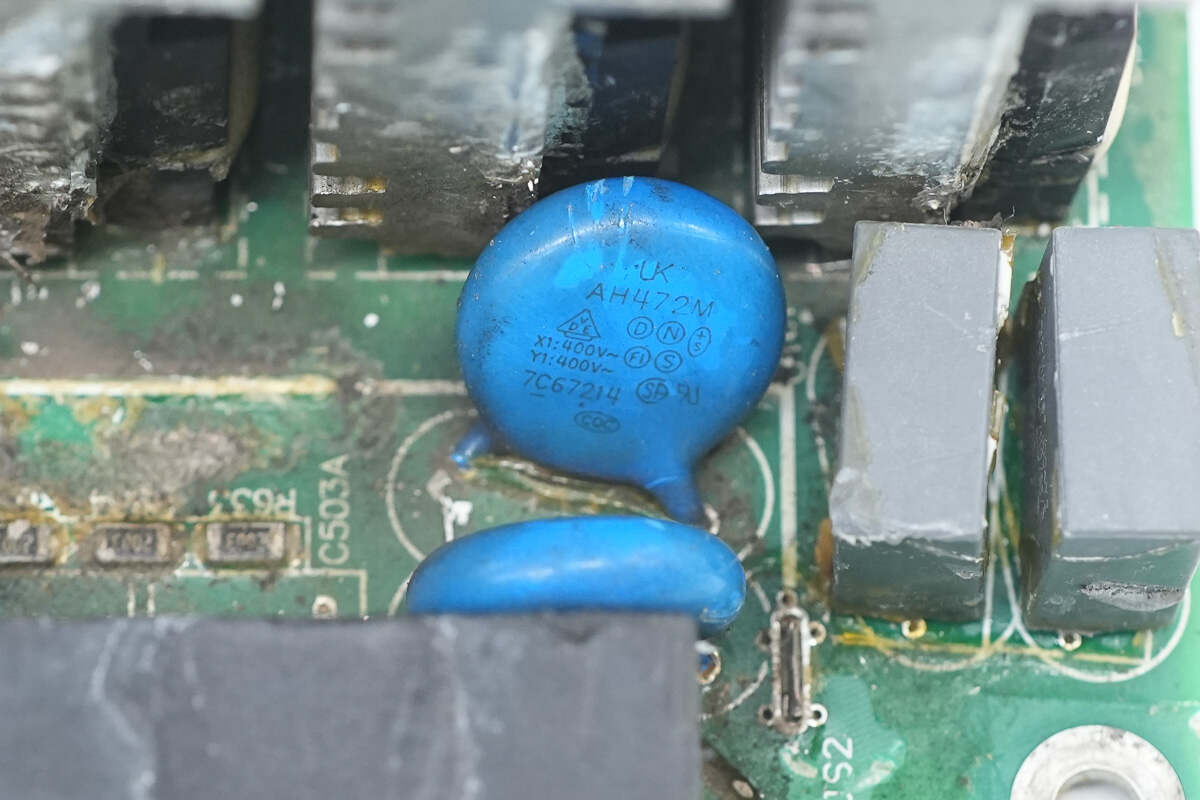
The blue Y capacitors are from Walsin.
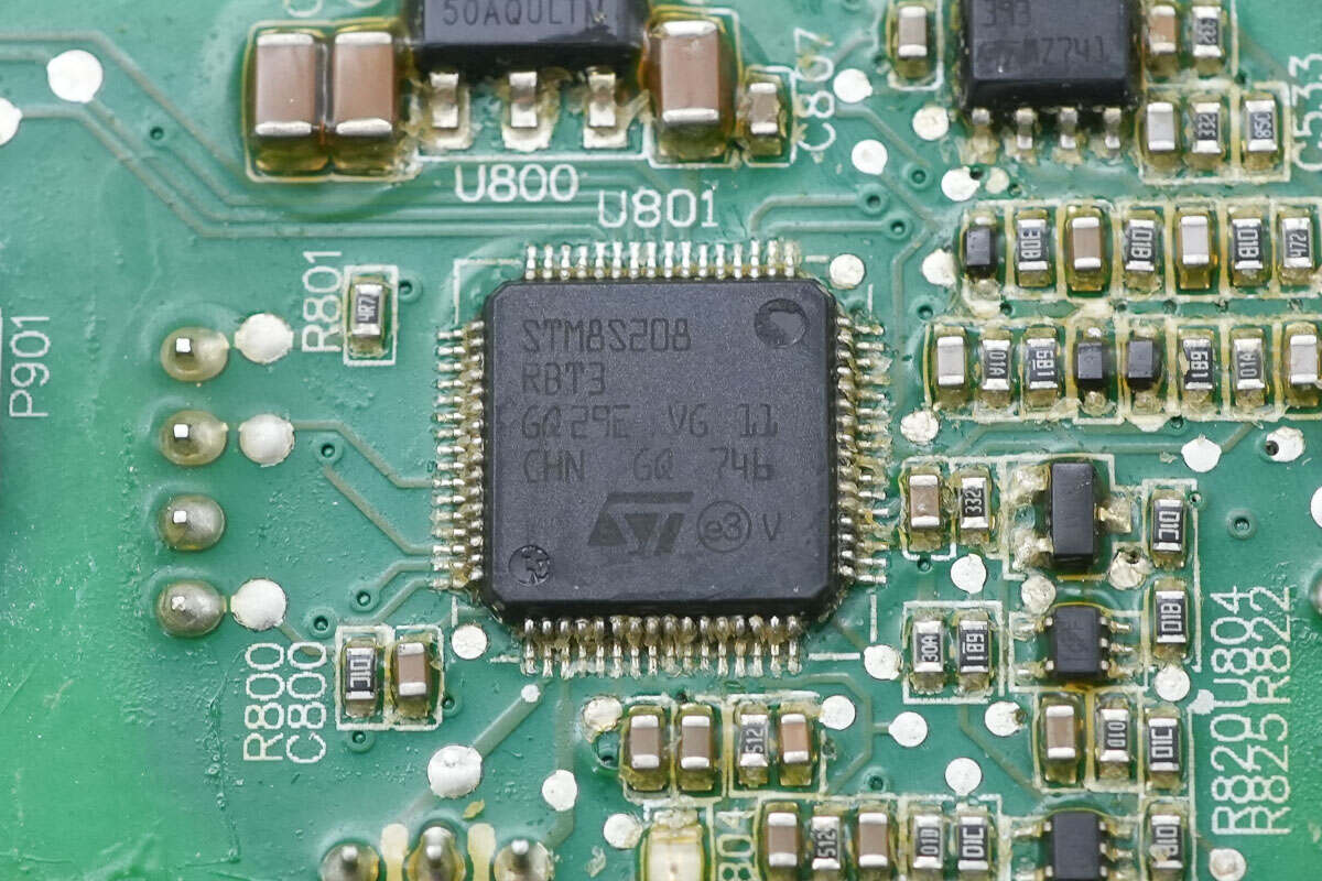
The MCU is from STMicro, model STM8S208RBT3. It features an STM8 core, with a clock speed of 24MHz, 128KB of Flash, and 6KB of SRAM. It supports a working temperature range of -40 to 125°C and includes a CAN 2.0 B bus interface. The package is LQFP64.
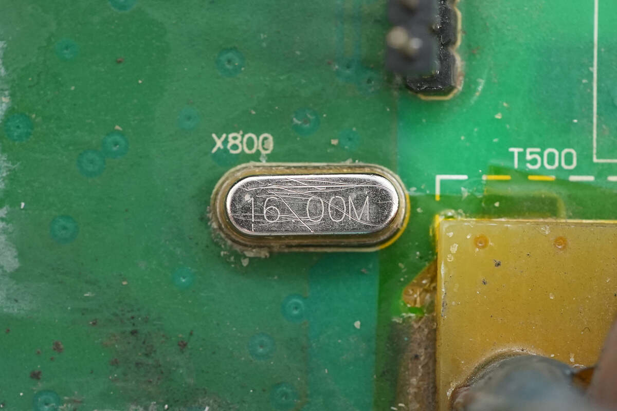
The clock crystal oscillator has a frequency of 16.00MHz.
This is the voltage regulator chip that powers the MCU.
A close-up of the LM2904AV dual op-amp.
A close-up of the LM393 dual voltage comparator.
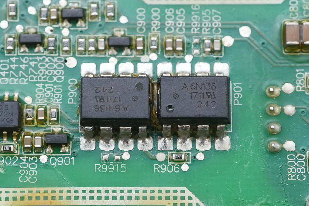
The two isolation optocouplers are from BROADCOM, model 6N136, and come in a DIP-8 package.

The CAN bus transceiver is from TI, marked with VP251, model SN65HVD251. It is a high-speed CAN transceiver that complies with the ISO 11898 standard, supports a transmission rate of 1Mbps, and comes in an SOIC8 package.
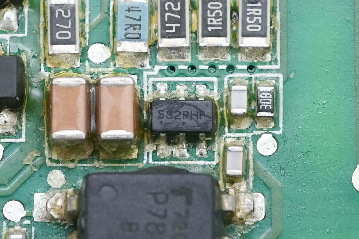
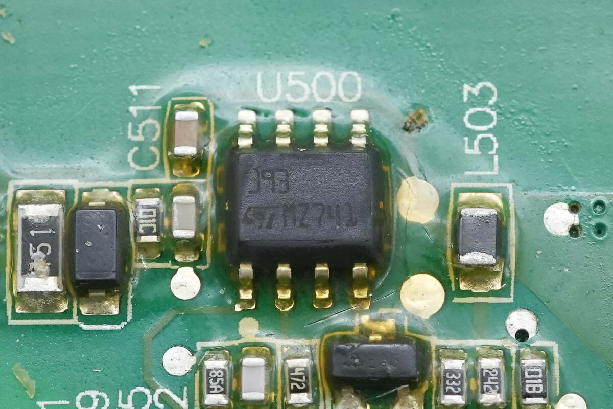
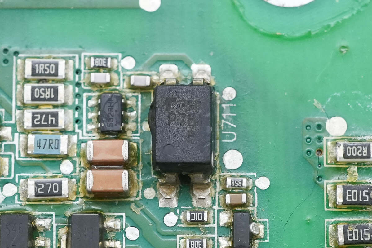
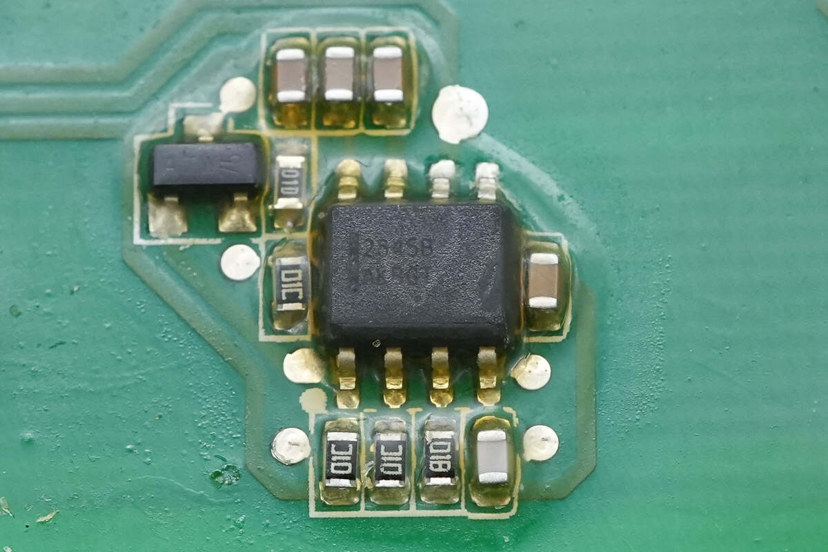
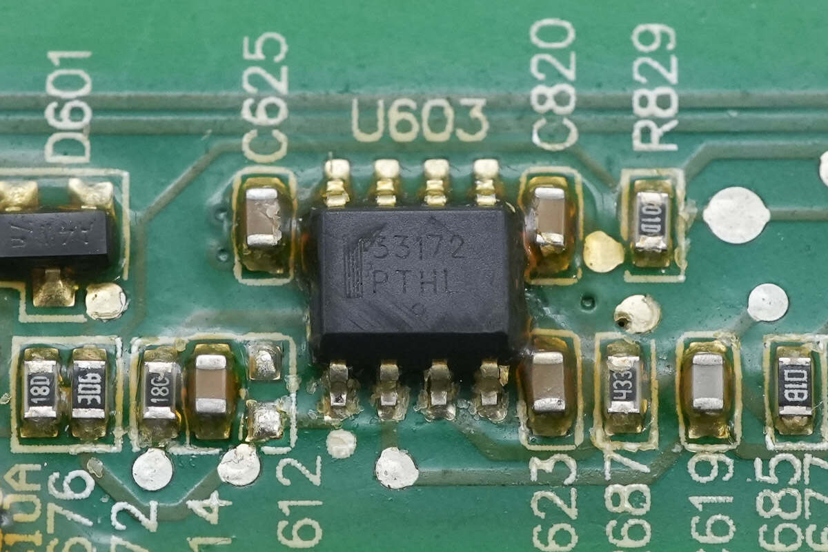
The auxiliary power chip is from Onsemi, marked with 532, model NCP1253BSN65T1G. It is a current-mode PWM controller with a switching frequency of 65kHz, featuring built-in soft start and slope compensation, and comes in a TSOP-6 package.
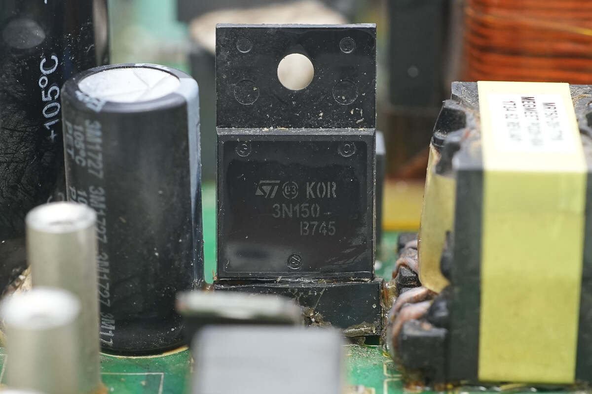
The MOSFET is from STMicro, model STFW3N150. It is an NMOS type, with a voltage rating of 1500V, an Rds(on) of 9Ω, and comes in a TO-3PF package.
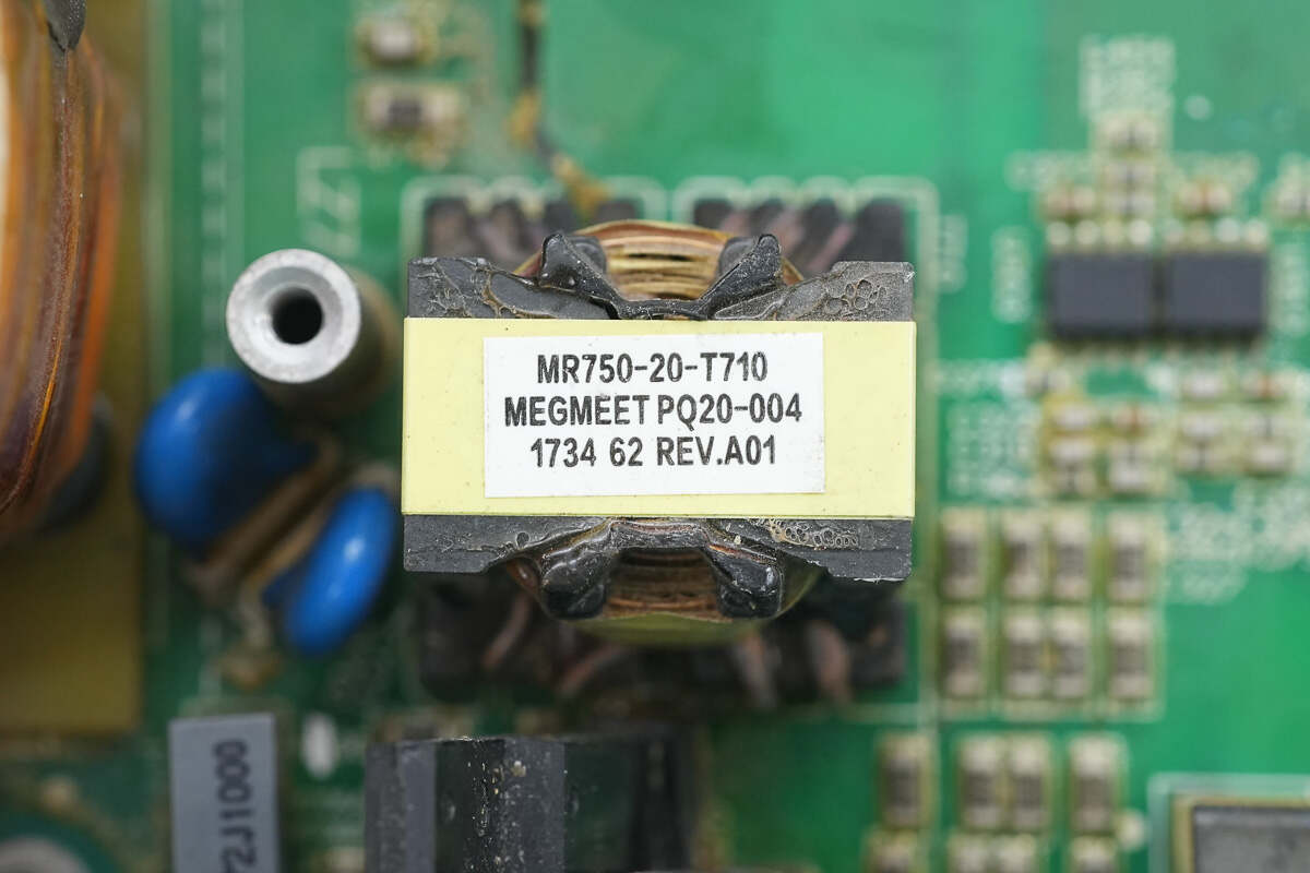
The transformer uses a PQ20 magnetic core.
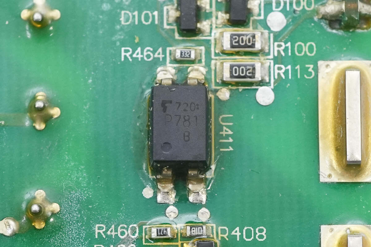
The Toshiba TLP781 optocoupler is used for output voltage feedback.
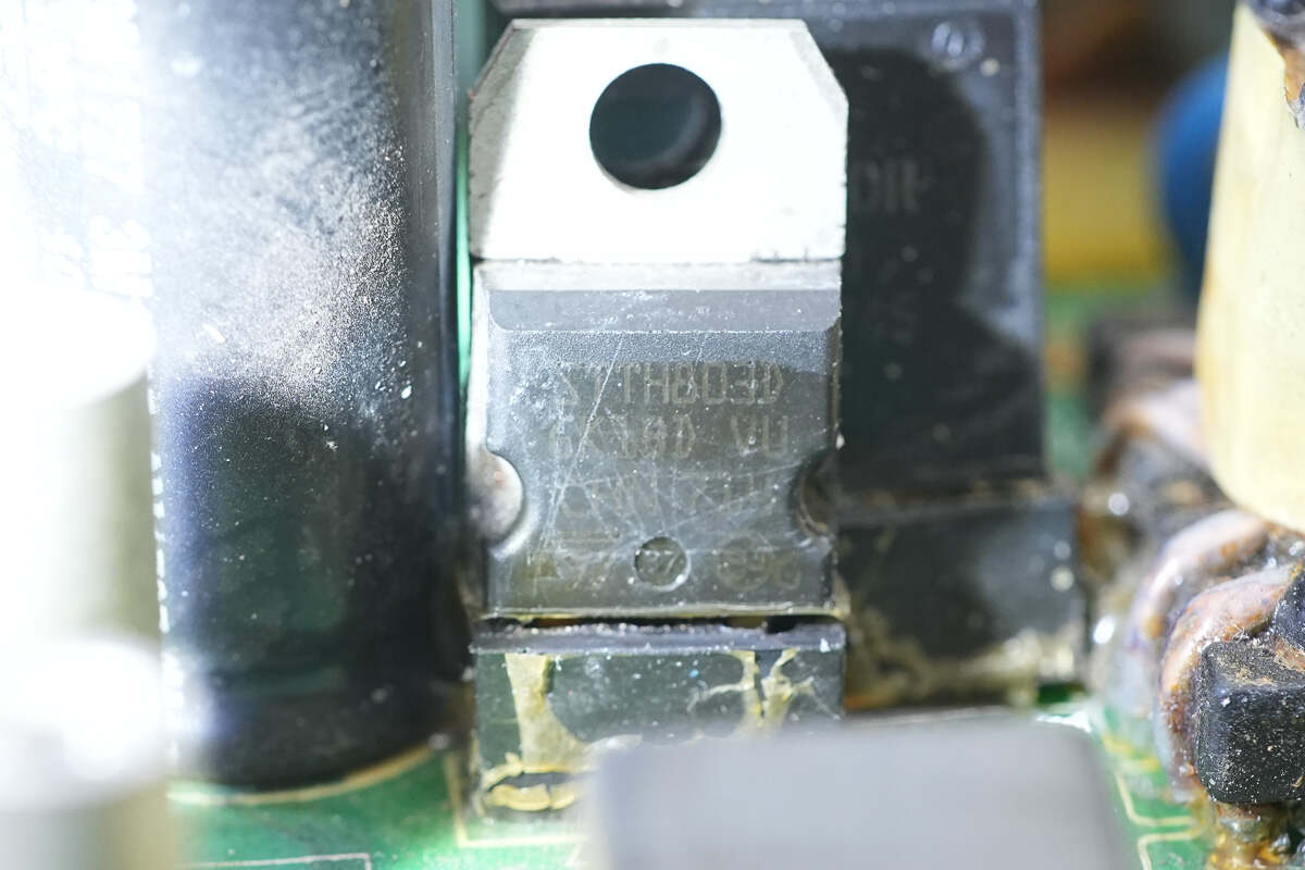
The rectifier is from STMicro, model STTH803D. It is an ultra-fast recovery diode with a rating of 300V, 8A, and comes in a TO-220AC package.
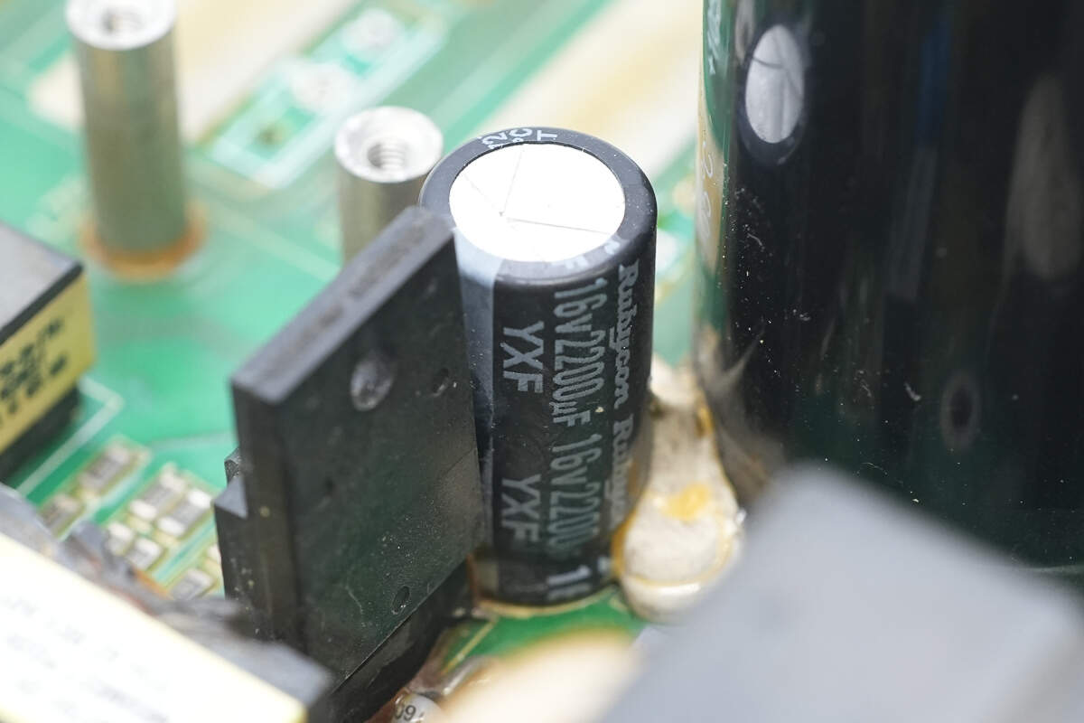
The filter capacitor is from Rubycon, with a specification of 16V, 2200μF.

A close-up of the DIODES AS78L05 voltage regulator chip.
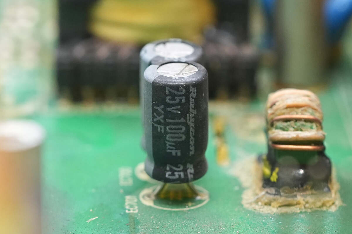
These two filter capacitors are from Rubycon, with a specification of 25V, 100μF.
The filter inductor is wound with magnetic ring.
A close-up of the transformer used to power the isolation driver and isolation amplifier.
The auxiliary power chip is from Onsemi, model UC2845B. It is a high-performance current-mode controller and comes in an SOIC-8 package.
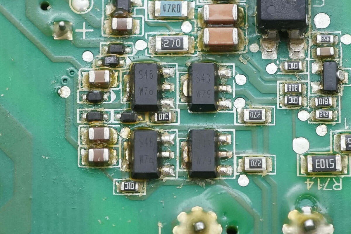
A close-up of the four driver transistors.
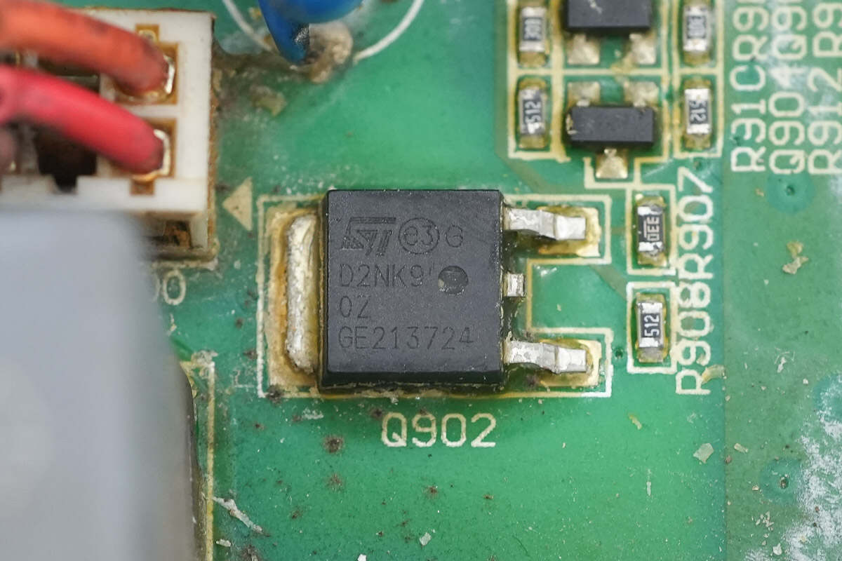
The discharge MOSFET is from STMicro, model STD2NK90ZT4. It is an NMOS type, with a voltage rating of 900V, an Rds(on) of 6.5Ω, and comes in a DPAK package.
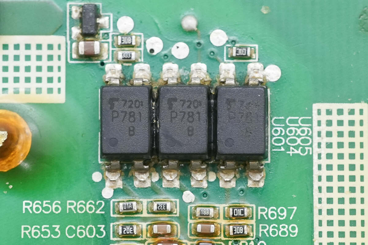
The Toshiba TLP781 optocoupler is used for feedback control.
A close-up of the LM2904AV dual op-amp.
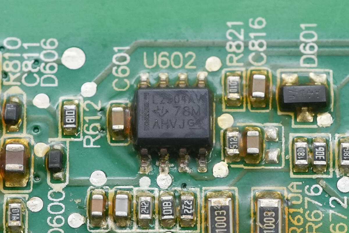
The op-amp is from Onsemi, model MC33172. It is a single-supply dual op-amp and comes in an SOIC-8 package.
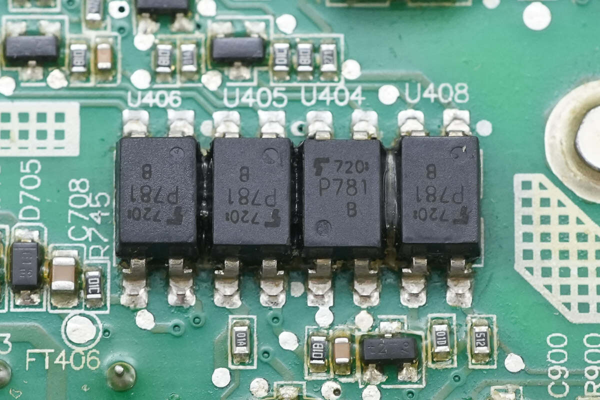
The four TLP781 optocouplers are used for communication between the MCU and the PFC controller.
The TLP781 optocoupler is used for soft start relay control.
A close-up of the rubber pad used to support the PCBA module.
The filter capacitor is from Rubycon, with a specification of 16V, 1500μF.
A close-up of the filter inductor.
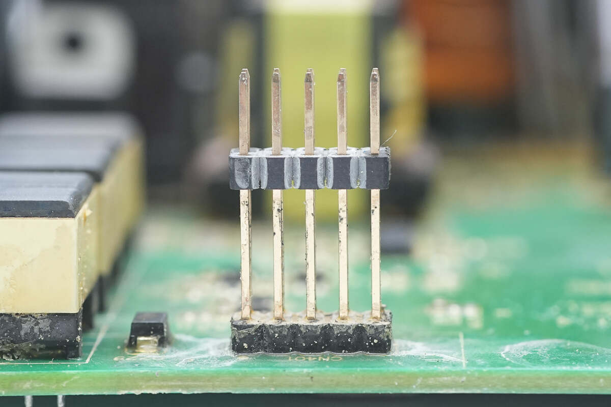
A close-up of the reserved communication header pins.
A close-up of the grounding terminal of the PCBA module.

Well, those are all components of the MEGMEET MR750‑20V 15 kW DC Charging Module.
Summary of ChargerLAB
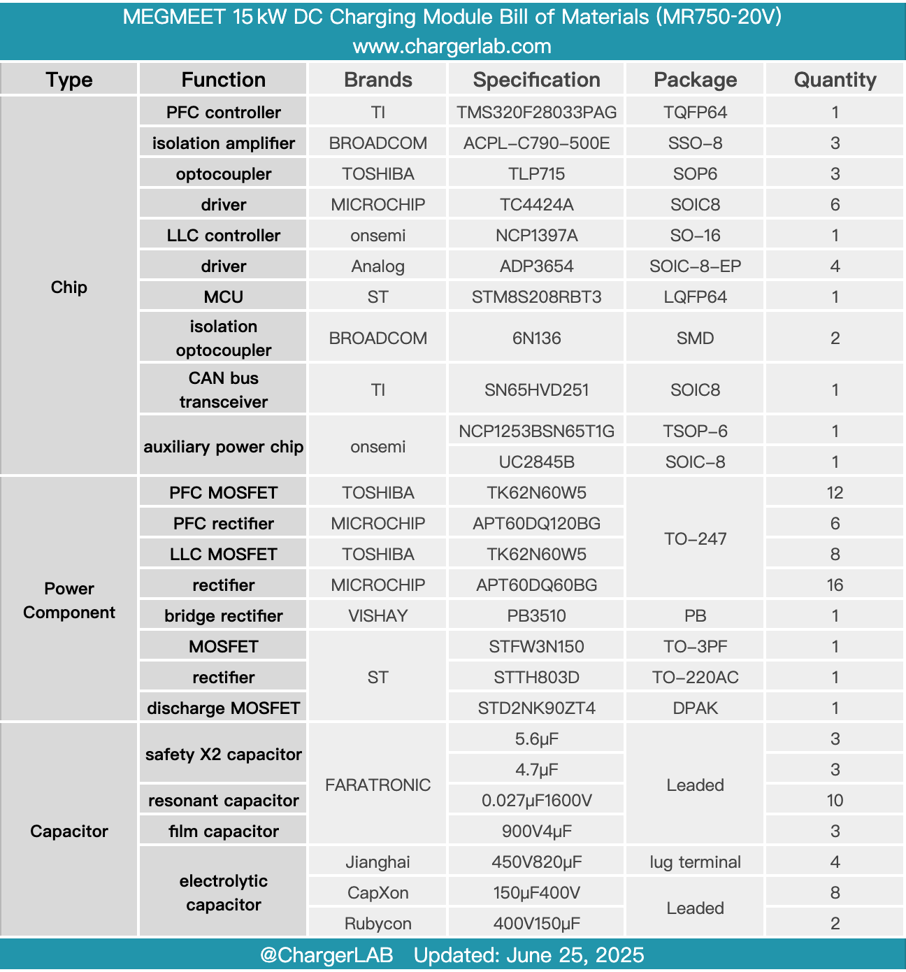
Here is the component list of the MEGMEET MR750‑20V 15 kW DC Charging Module for your convenience.
It supports an output power of 15kW, with a three-phase AC input and an input voltage of 380V. The module's DC output voltage range is 250~750V, and the rated output current is 20A. The front of the charging module is equipped with a grille, while the interior features a cooling fan and status indicators. The rear has connection terminals, simplifying installation and maintenance.
After taking it apart, we found that it uses a metal shell, and the PCBA module is divided into PFC and LLC parts. PFC uses a TI TMS320F28033PAG controller, the LLC controller uses an Onsemi NCP1397A, and the MCU uses an STMicro STM8S208RBT3.
The PFC MOSFET and LLC MOSFET are from Toshiba, while both the PFC rectifier and LLC rectifier are from Microchip. The PFC MOSFET driver is powered by an isolation transformer and controlled by an optocoupler, while the LLC MOSFET is driven using a driver paired with an isolation transformer. The auxiliary power chip is from Onsemi.
Both the front and back of the PCBA module are coated with conformal coating, with glue applied at capacitor and resistor positions to reinforce and seal, enhancing insulation. The safety X2 capacitor, soft start relay, and output capacitors are soldered onto a vertical PCB, making efficient use of space. All components are from well-known brands, combined with multiple protective measures to ensure stable operation even under harsh conditions.
Related Articles:
1. Teardown of Belkin 240W Dual USB-C Braided Cable
2. Teardown of Lenovo Legion 245W GaN Adapter (LA245)
3. Teardown of DJI Original 240W Power Adapter for Mavic 4 Pro (CDX341-240)