Introduction
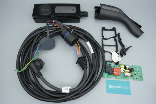
This teardown examines a Lincoln-branded 1760W portable EV charger. The unit features a classic split design, with an overall cable length of approximately 6.6 meters, and includes a storage bag for convenient in-vehicle use.
The charger is equipped with a 10A plug, supports an 8A charging current, and delivers a charging power of 1760W. The following section presents a detailed disassembly of this charger, focusing on its internal design and component selection.
Product Appearance

The charger is packaged in a black storage bag.
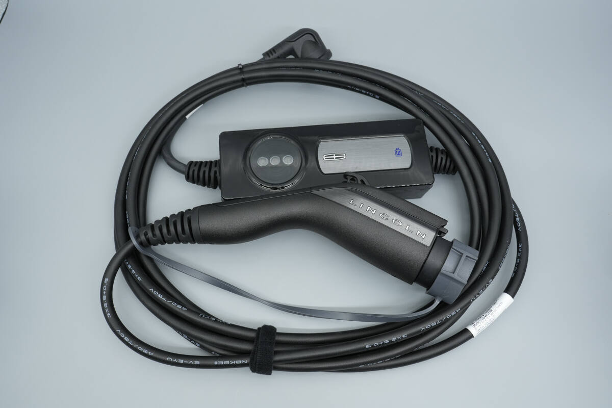
The plug, control box, and connecting cable are all finished in black, and a hook-and-loop cable tie is included for cable management.
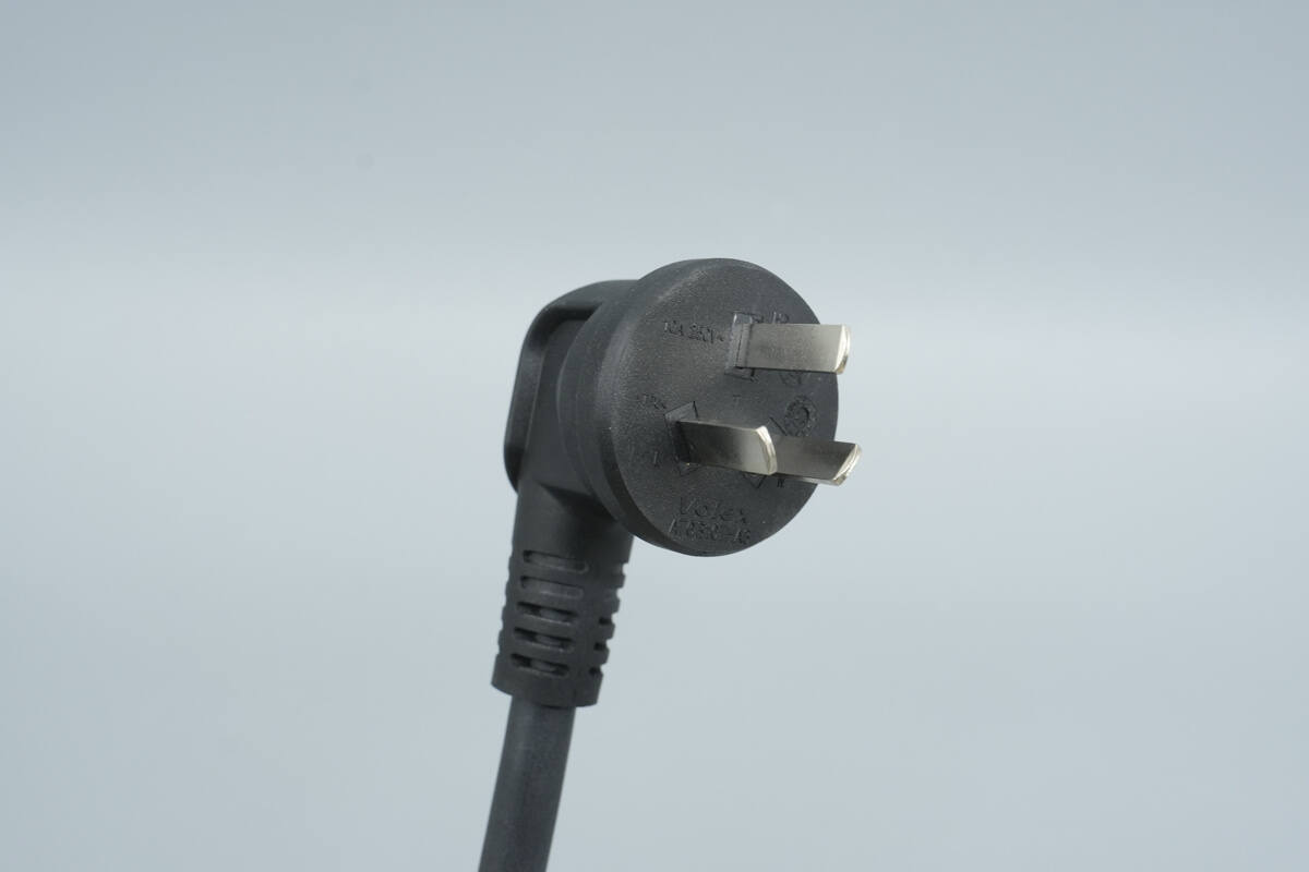
The input plug is a three-prong type.
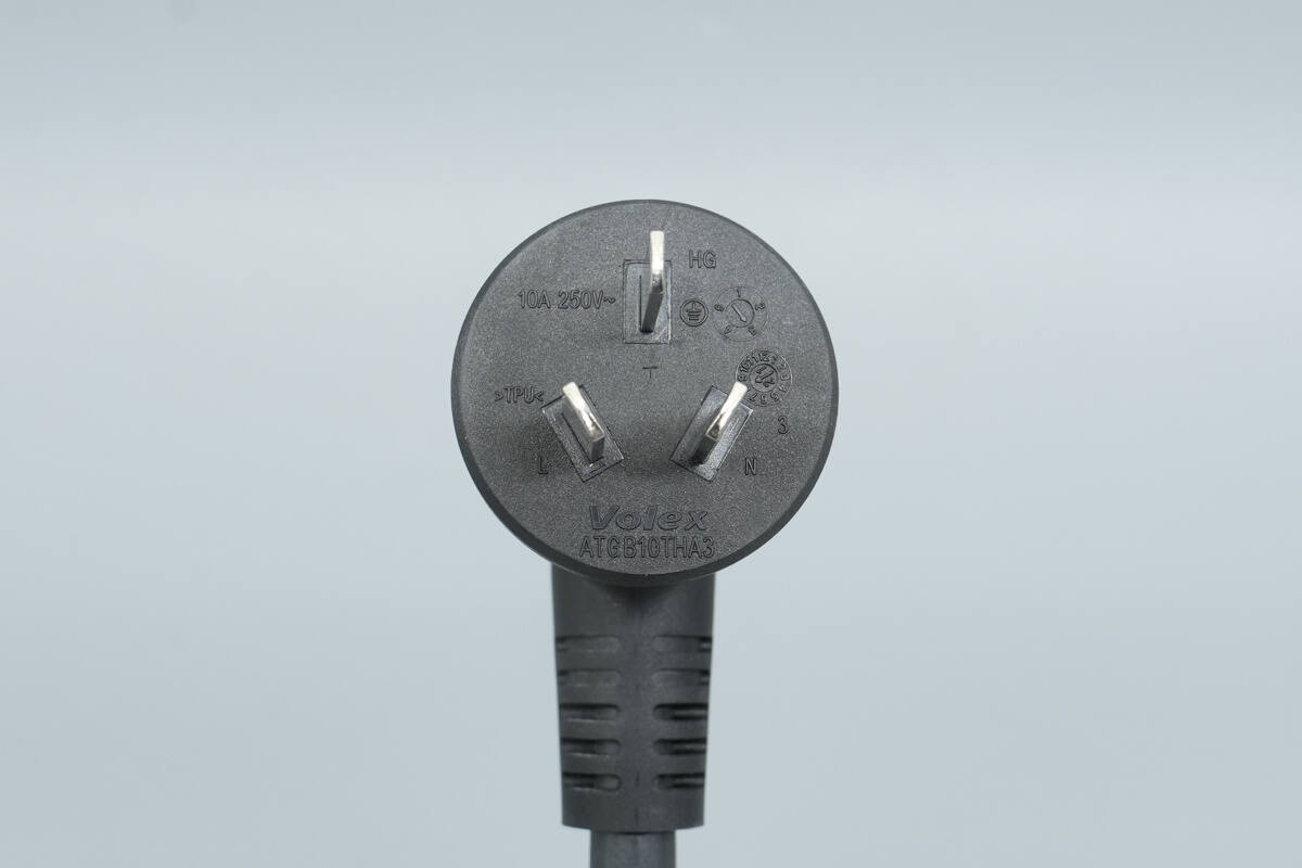
The rated specification is 10A, 250V~.
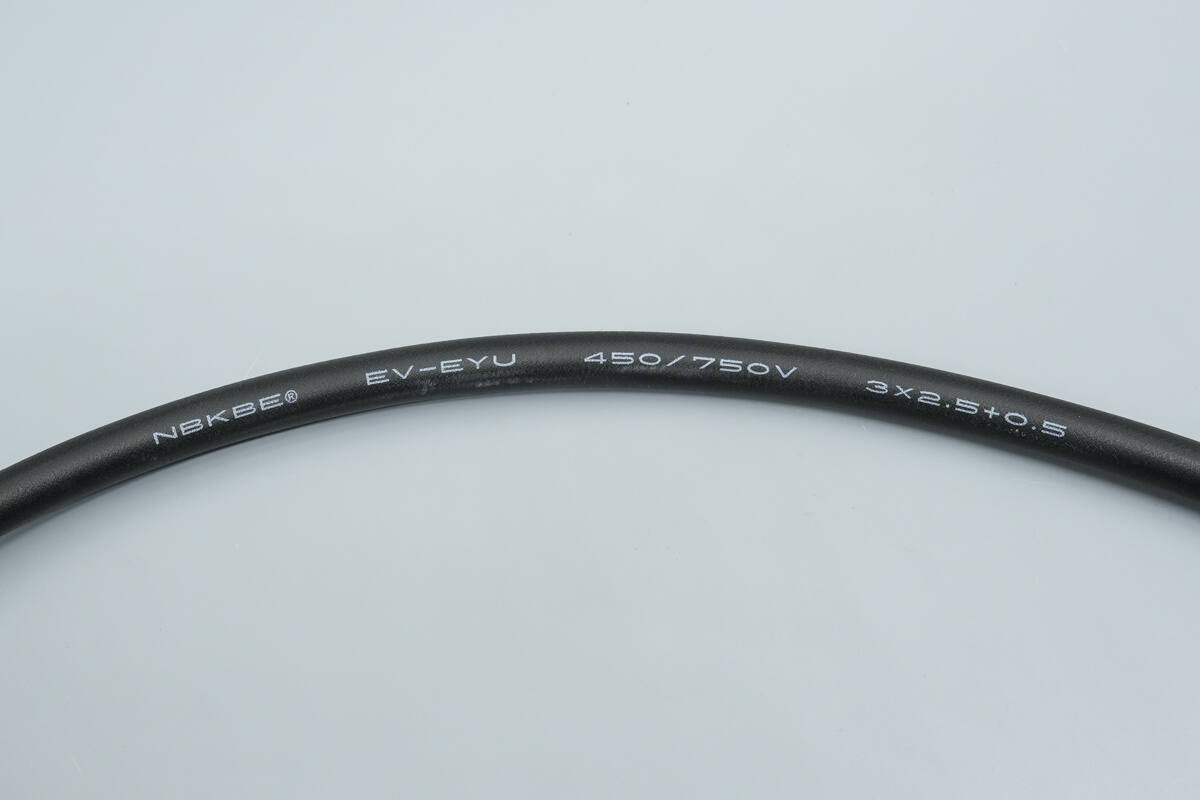
The cable specification is 3 × 2.5 mm² + 1 × 0.5 mm².
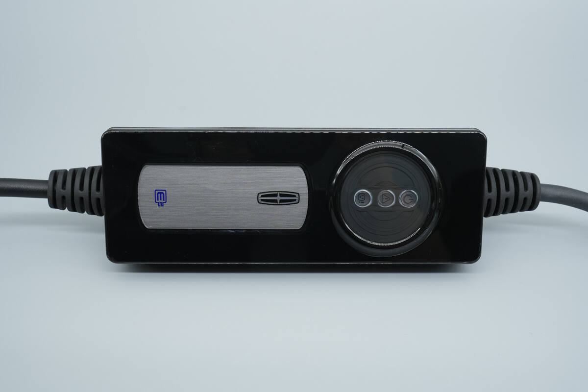
The charging control box features the Lincoln logo printed at the center, with indicator lights positioned on the right side.
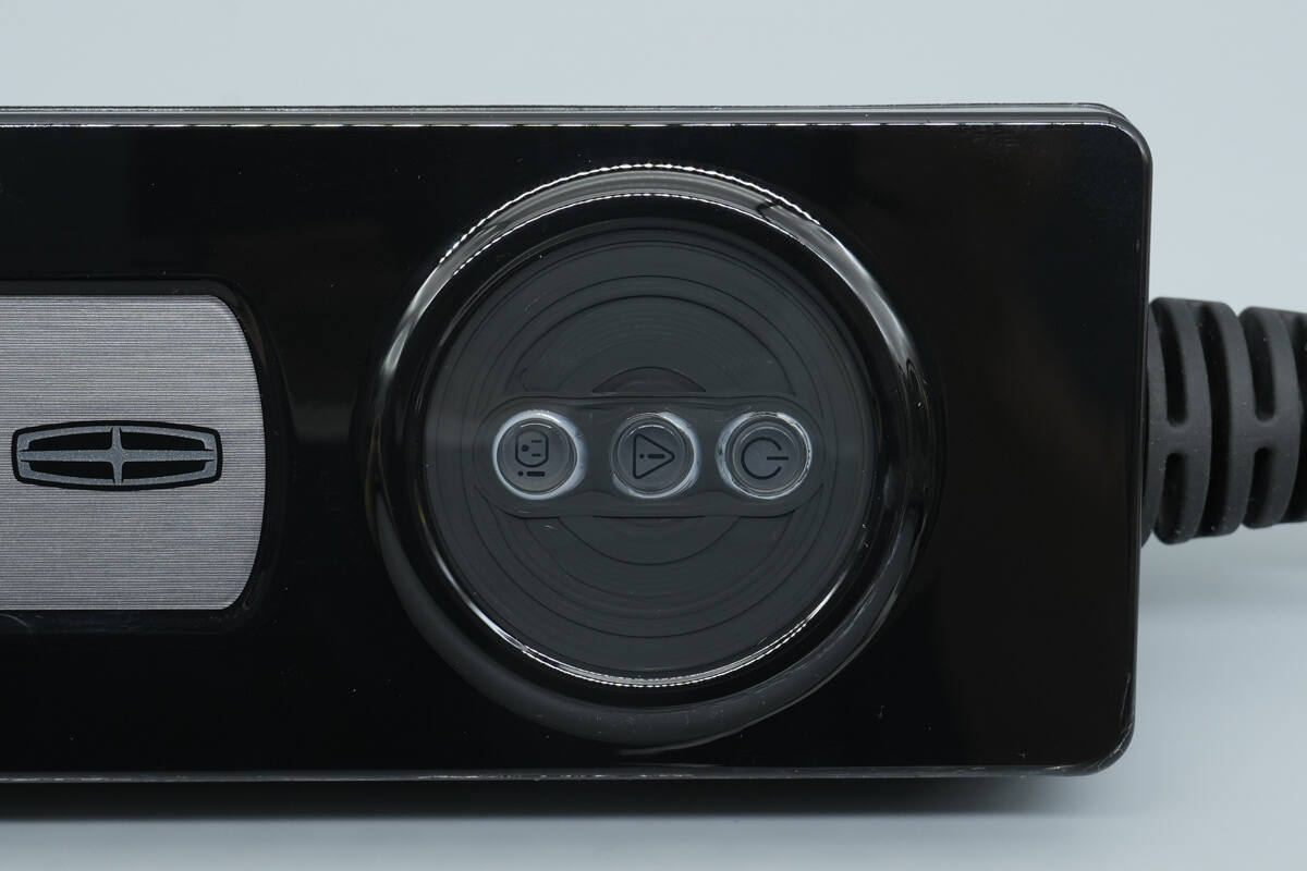
The indicator lights are used for power status indication and fault/alarm indication.
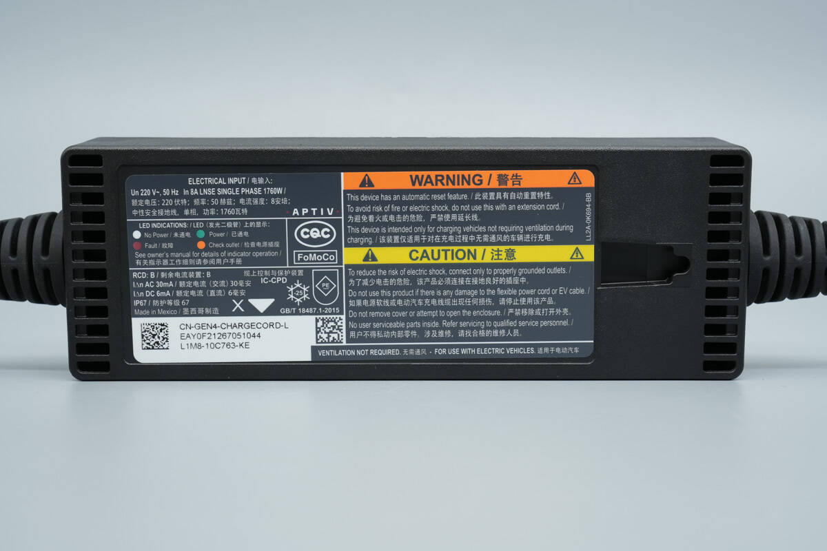
An information label is affixed to the back of the control box.
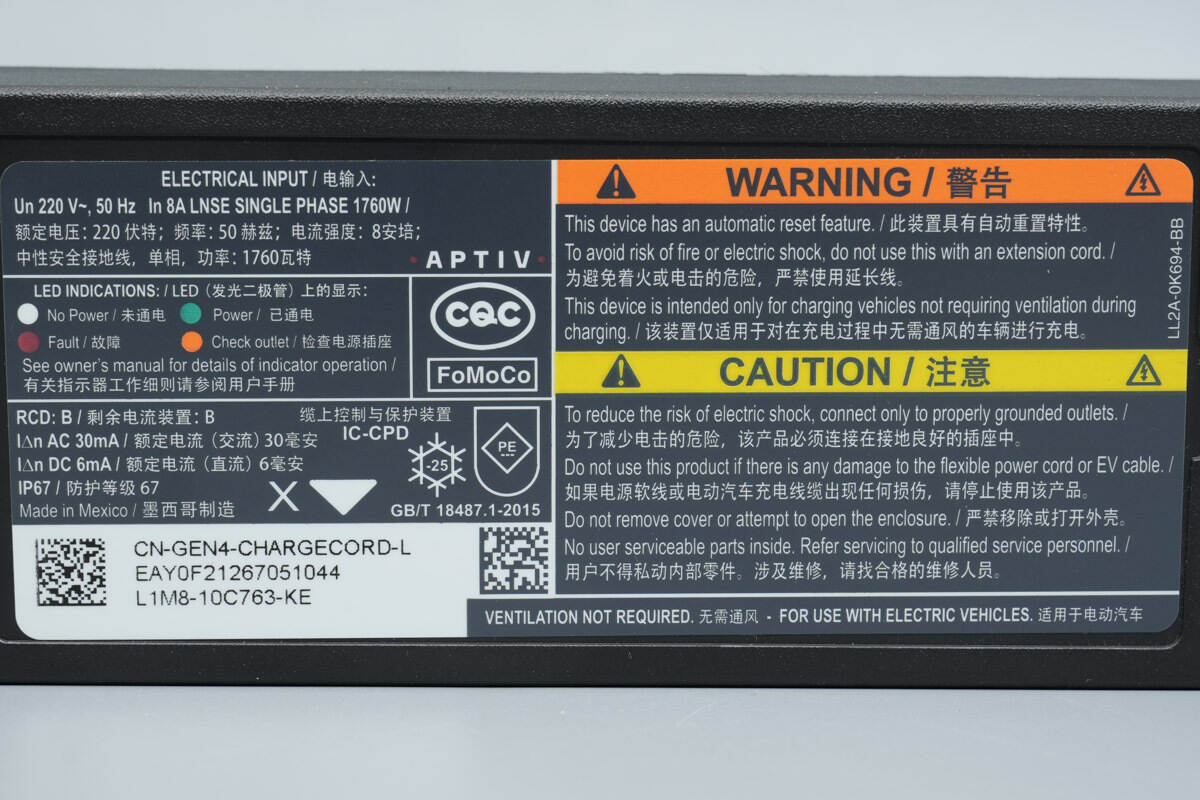
Rated voltage: 220 V; frequency: 50 Hz; current: 8 A; neutral, protective earth; single-phase; power: 1760 W.
IΔn AC 30 mA / rated residual operating current (AC) 30 mA
IΔn DC 6 mA / rated residual operating current (DC) 6 mA
IP67 / ingress protection rating 67
Made in Mexico
Manufactured by APTIV (Aptiv) connector OEM.
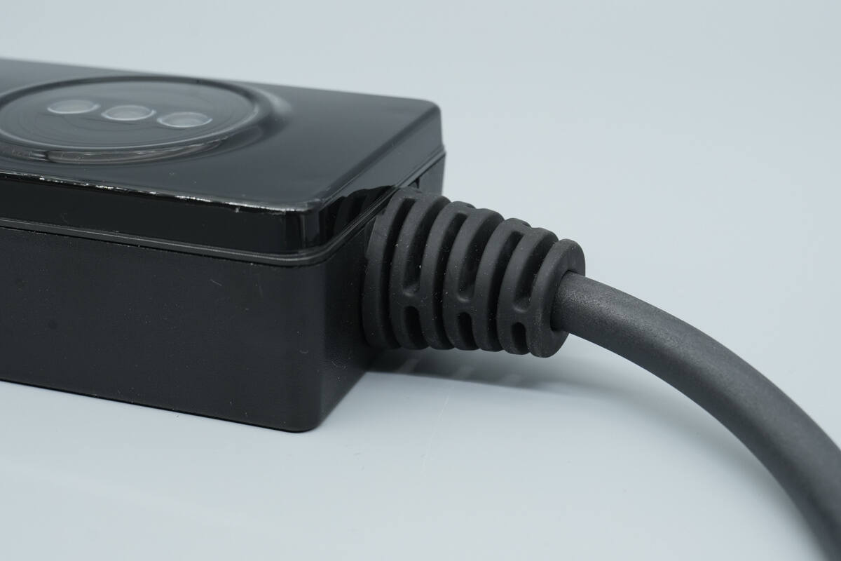
A rubber sleeve is provided at the junction between the input cable and the charging control box for strain relief and bend protection.
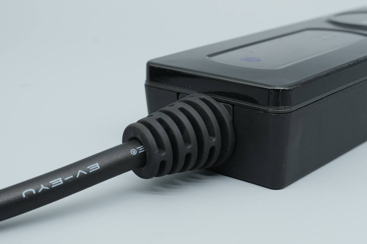
A rubber sleeve is also provided at the junction between the output cable and the charging control box.
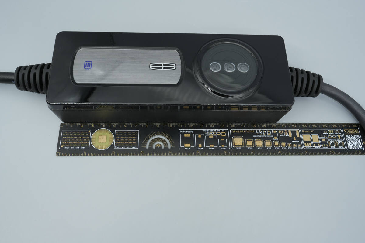
The length of the charging control box is about 205 mm (8.071 inches).
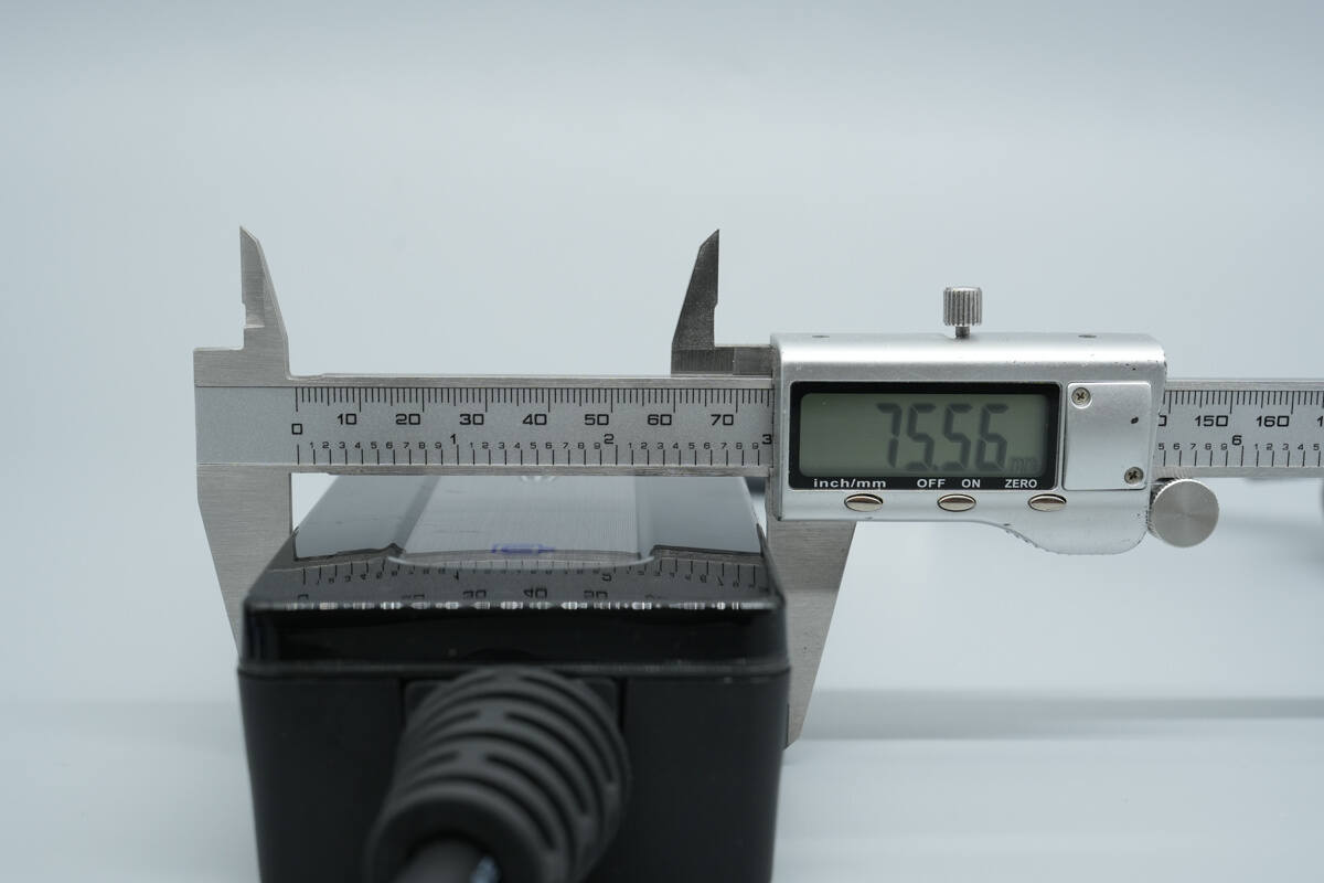
The width is about 75.6 mm (2.98 inches).
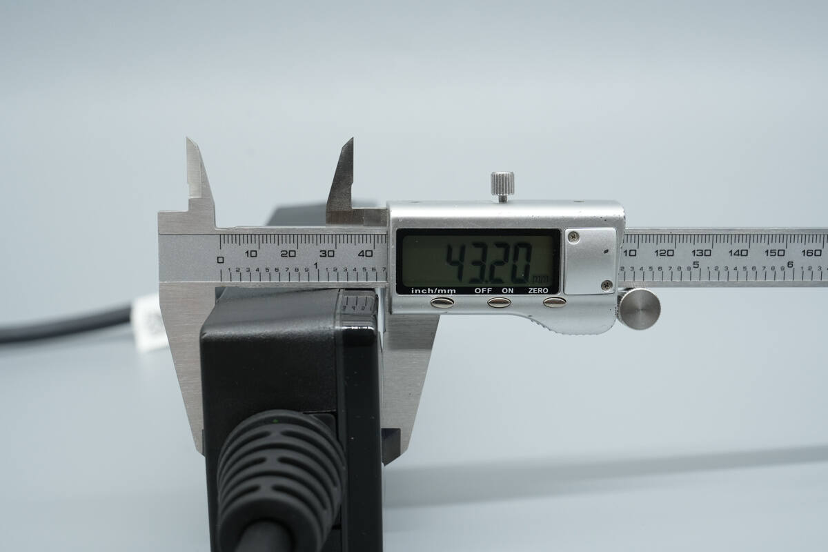
The thickness is about 43.2 mm (1.7 inches).
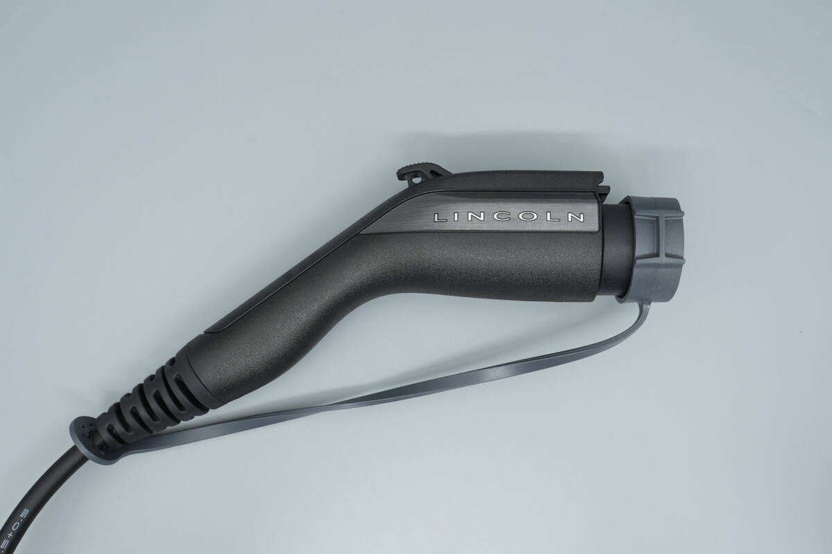
The side of the charging connector is printed with “LINCOLN” and features an integrated dust cover.
An unlock button is located on the top of the charging connector.

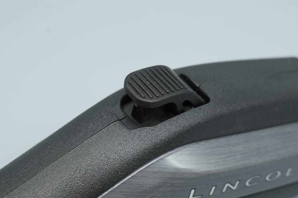
Close-up of the locking latch.

A rubber sleeve is provided at the junction between the charging connector and the cable for bend relief protection.

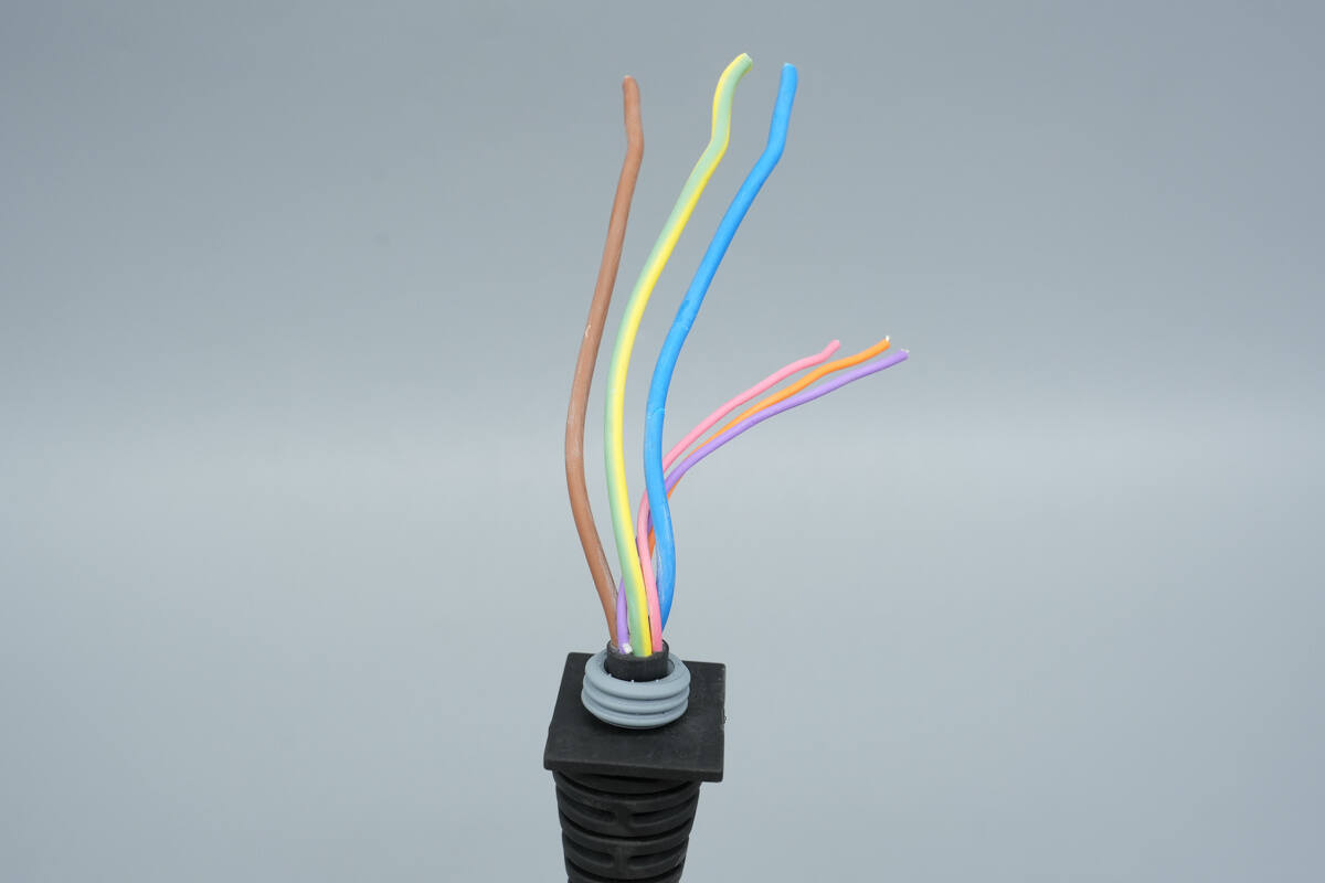
Close-up of the charging connector head, featuring a 7-pin AC connector design compatible with a wide range of electric vehicles from major automotive brands.
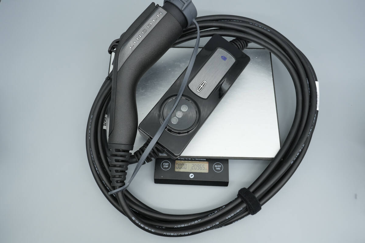
The weight is about 2097 g (73.97 oz).
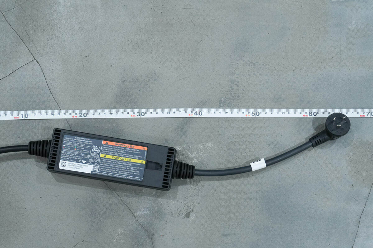
The total length is about 6.6 meters.
Teardown
Next, let's take it apart to see its internal components and structure.
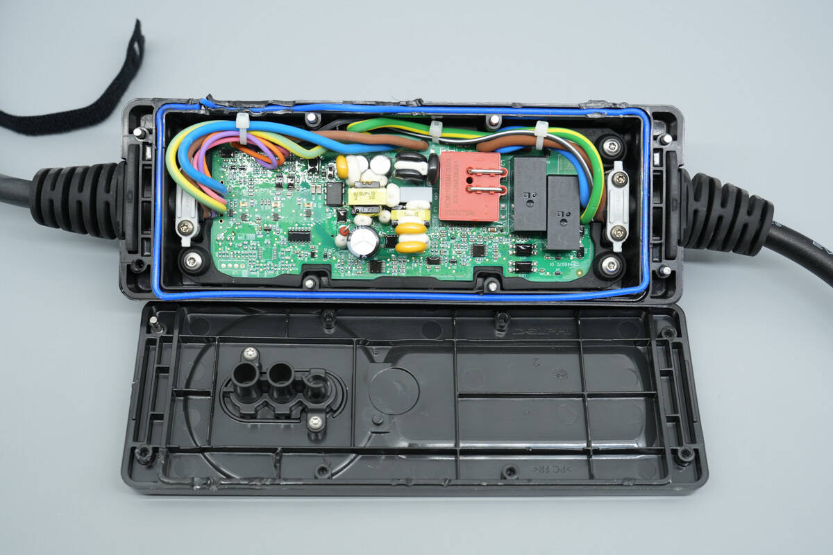
The charging control box is disassembled along the housing seam.
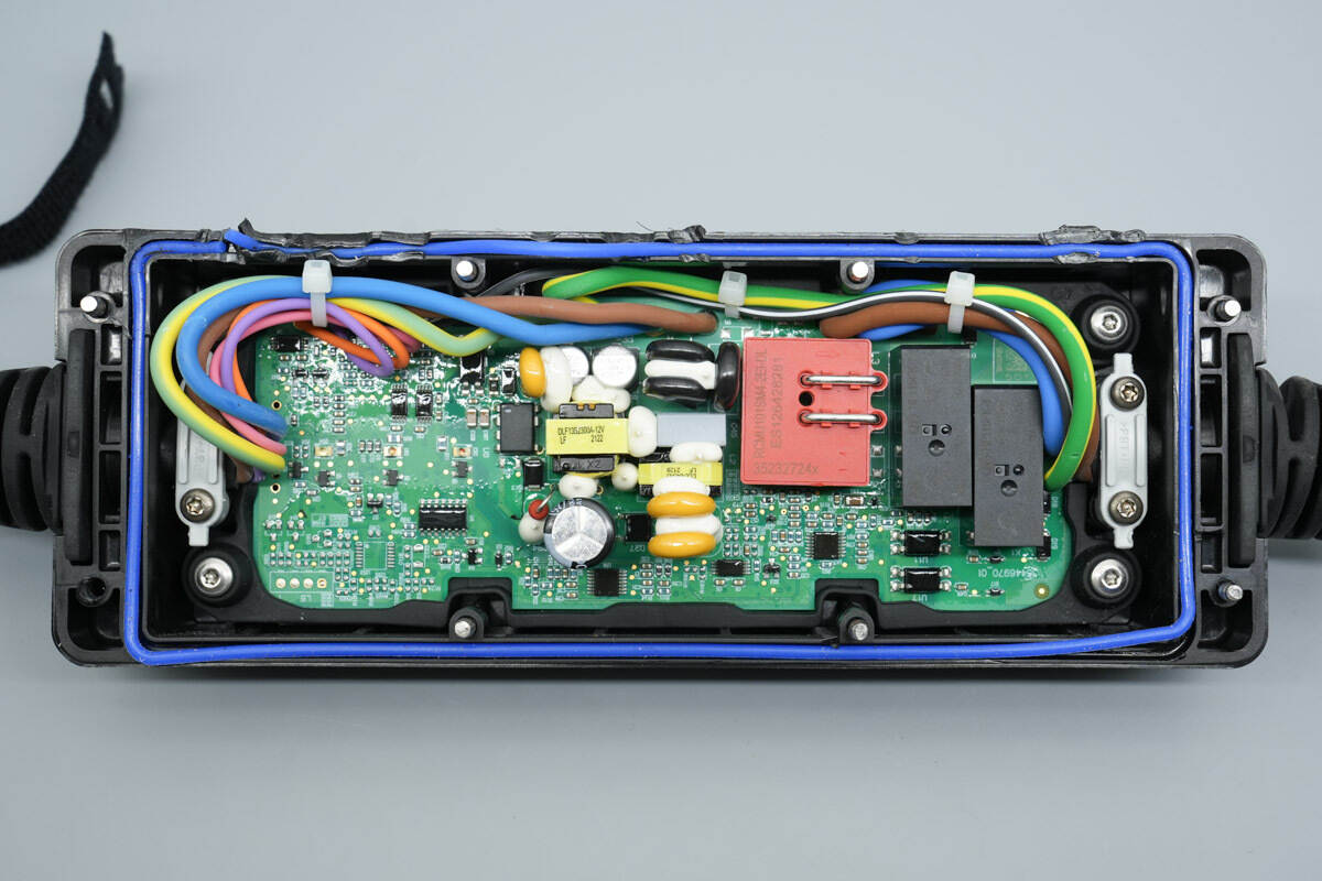
A blue sealing gasket is present along the housing seam of the control box. The PCBA module is secured with screws and a retaining plate. The connection wires on both sides are also fixed with retaining plates, while the input and output wires are connected via soldering.
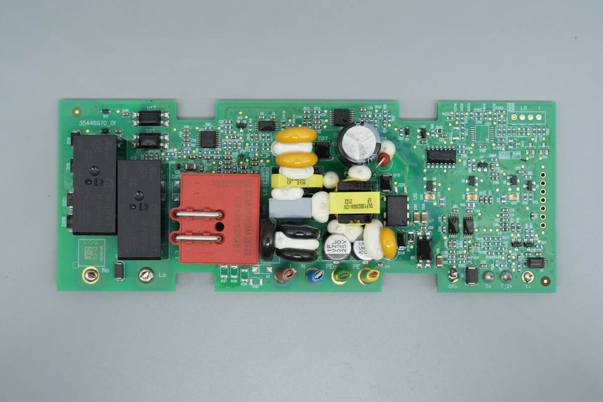
The front side of the PCBA module features components including relays, optocouplers, a current transformer, varistors, an X2 safety capacitor, a bridge rectifier, a high-voltage filter capacitor, a main control chip, a transformer, operational amplifiers, and LED indicators.
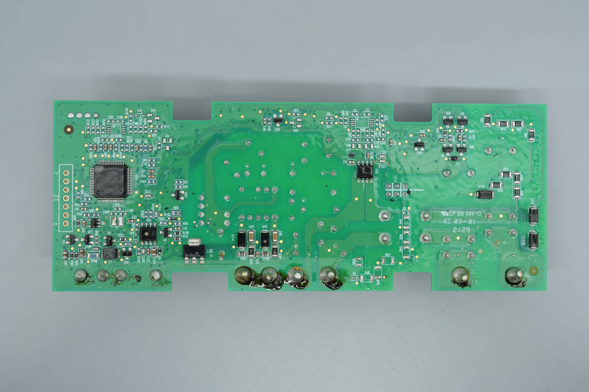
The reverse side contains an MCU, a regulator chip, and a current sensing chip.
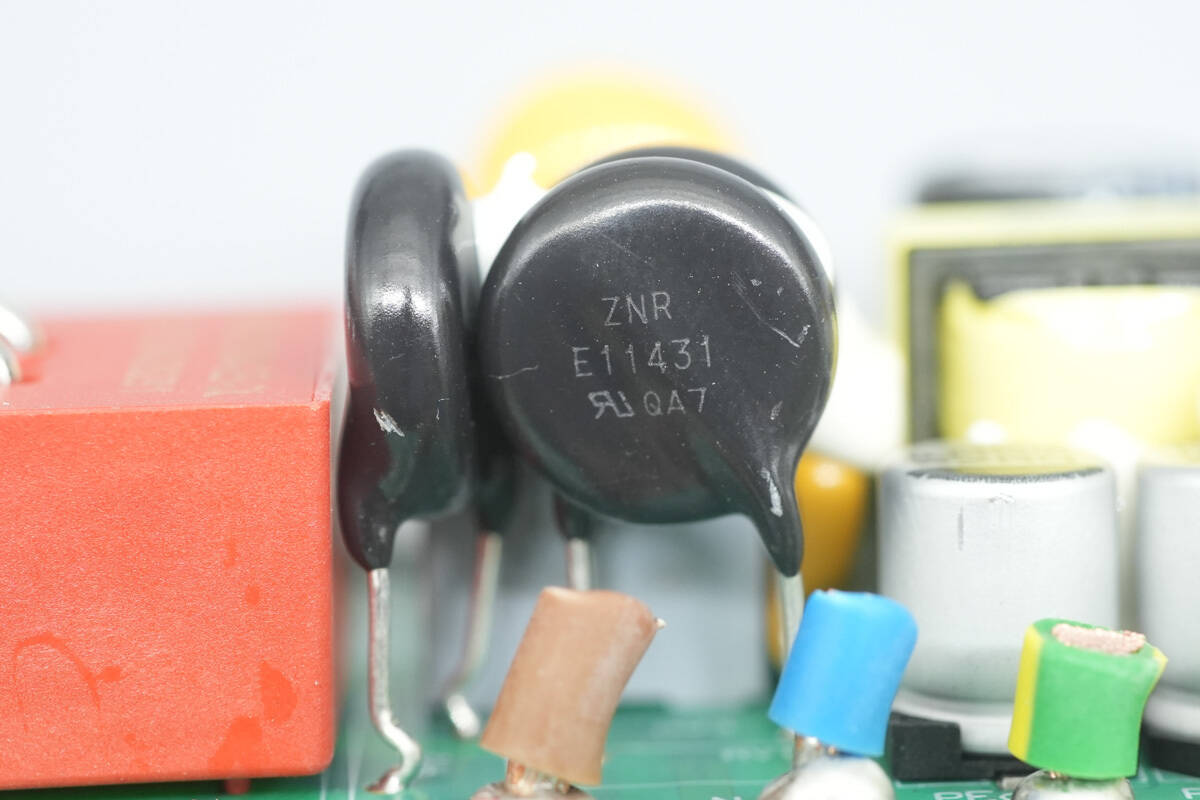
The varistors are from Panasonic and are marked ZNRE11431, part number ERZE11A431, used for absorbing overvoltage surges.
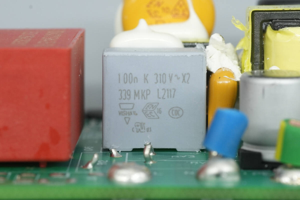
The safety X2 capacitor is from Vishay, with a capacitance of 0.1 μF.

The common mode choke and surrounding components are reinforced with adhesive.
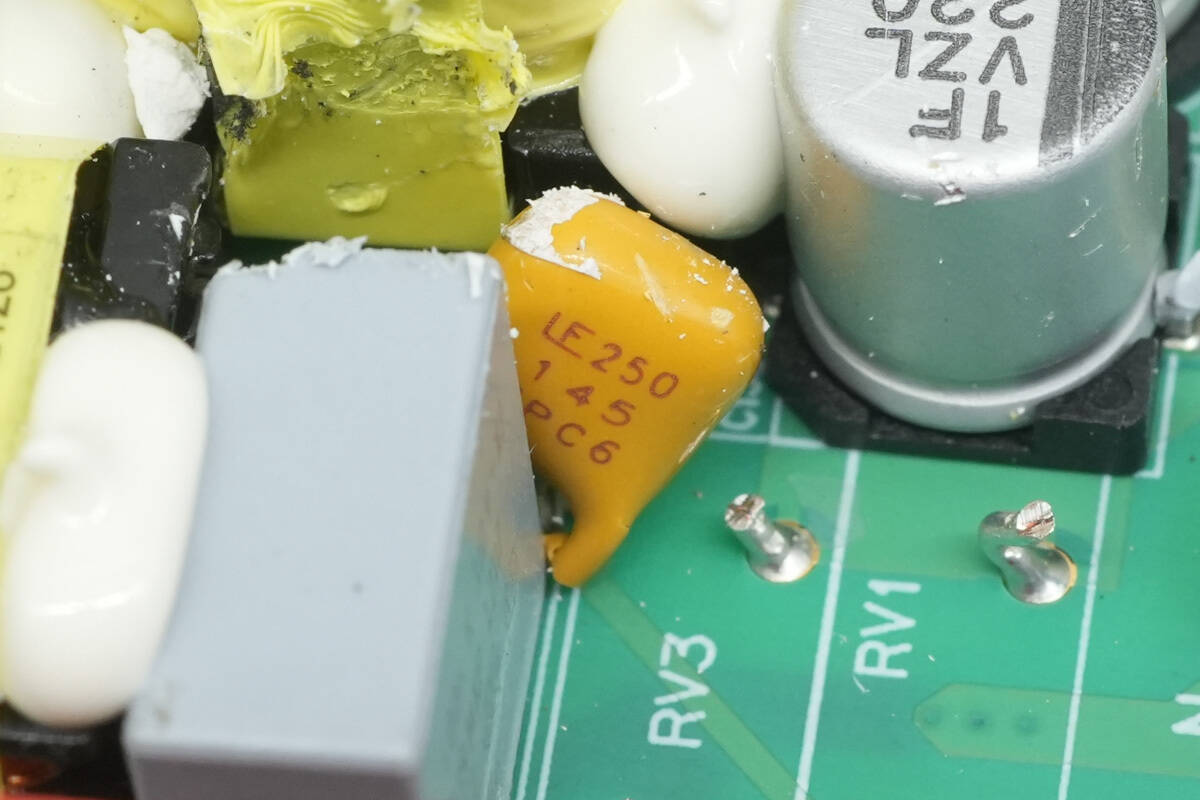
The resettable fuse is from Littelfuse, model 250R145, used for input overcurrent protection.
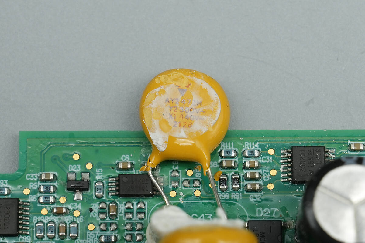
The Y capacitor is from Vishay, part number AY2472M.
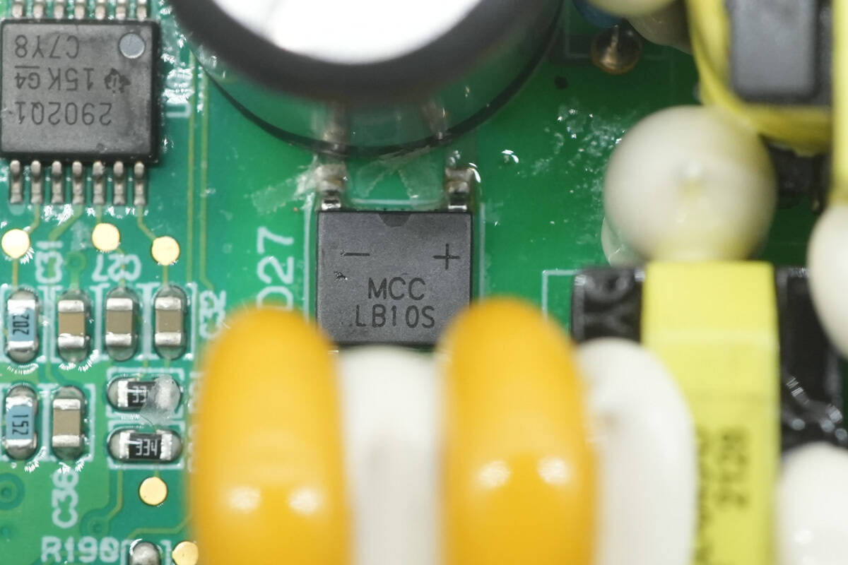
The bridge rectifier is from MCC, marked LB10S, model LMB10S, rated at 1000 V, 1 A, and packaged in an LMBS-1 package.
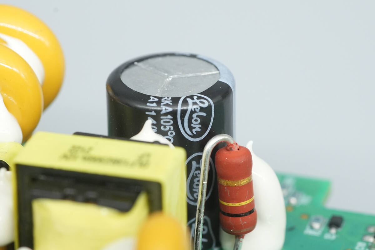
The high-voltage filter capacitor is from Lelon.
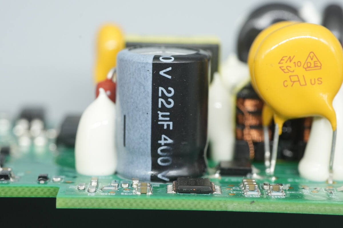
The high-voltage filter capacitor is rated at 22 μF, 400 V.
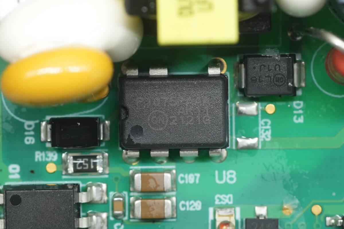
The master control chip is from Onsemi, model NCP1075. It integrates a 700 V MOSFET and features fixed-frequency current-mode control. It supports dynamic self-supply operation without the need for an auxiliary winding and comes in a PDIP-7 package.
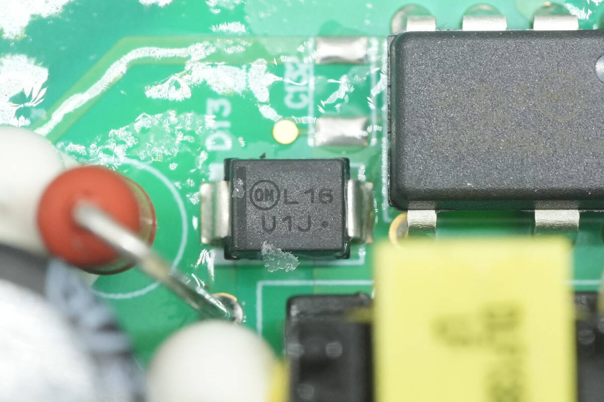
The diode used for circuit clamping is from Onsemi, marked U1J, model MURS160T3G, rated at 600 V, 1 A, and packaged in SMB.
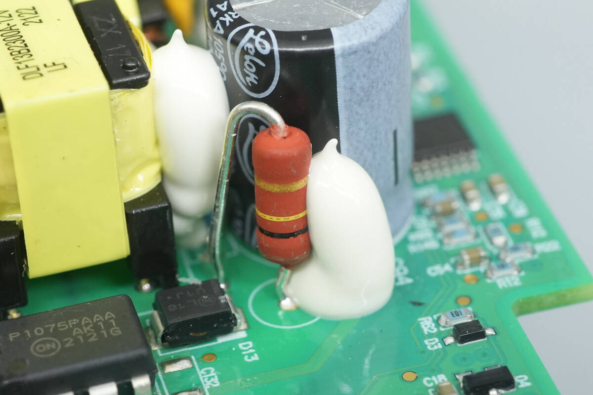
Close-up of the color band resistor used in the snubber circuit.
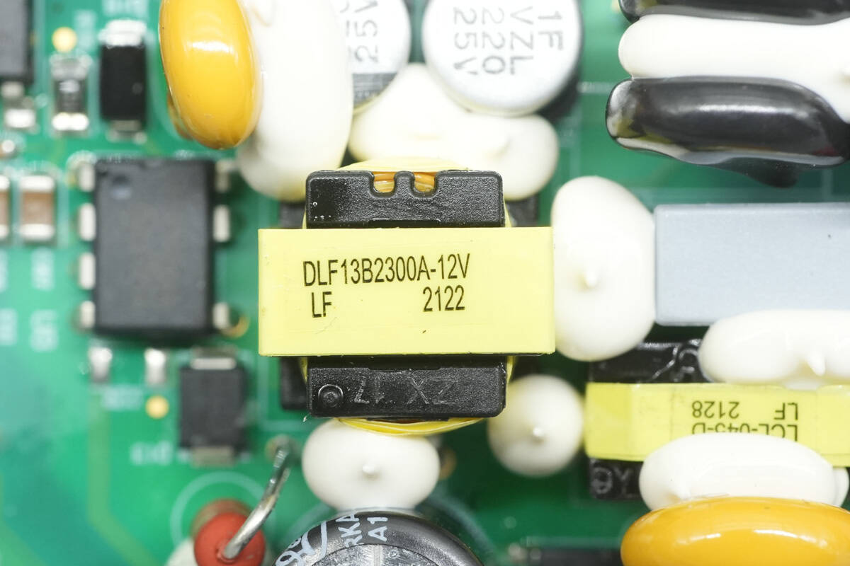
The edges of the transformer are reinforced with adhesive.
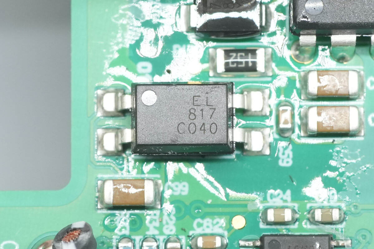
An Everlight EL817 optocoupler is used for output voltage feedback.
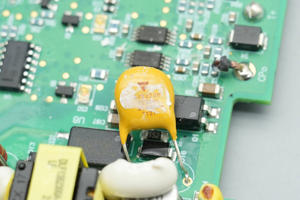
The Y capacitor is from Vishay, part number AY2222M.
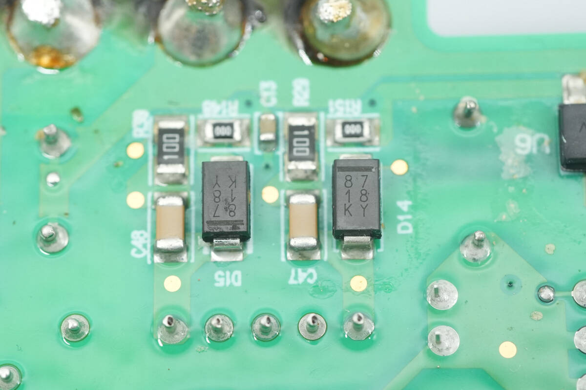
Two diodes marked 8718KY are used for output rectification.
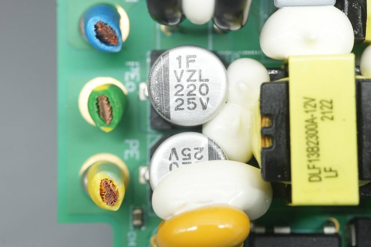
Two filter capacitors are rated at 220 μF, 25 V.
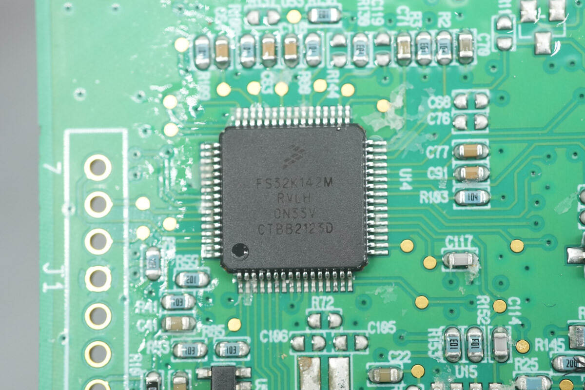
The MCU is from NXP, model S32K142MRVLH, part of the S32K1 series of 32-bit automotive microcontrollers. It features an ARM Cortex-M4F core with a maximum frequency of 80 MHz, 256 KB of internal Flash memory, and 32 KB of SRAM. The chip supports low-power UART, SPI, and I²C interfaces, as well as a CAN FD interface, and comes in a 64-pin LQFP package.
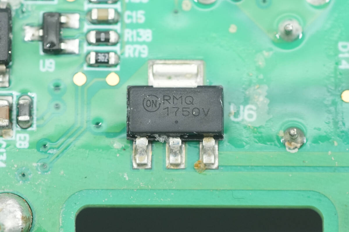
The regulator chip supplying power to the MCU is from Onsemi, marked 1750V, model NCV1117ST50. It supports an input voltage up to 20 V, provides a 5 V output, delivers up to 1 A of output current, and comes in an SOT-223 package.
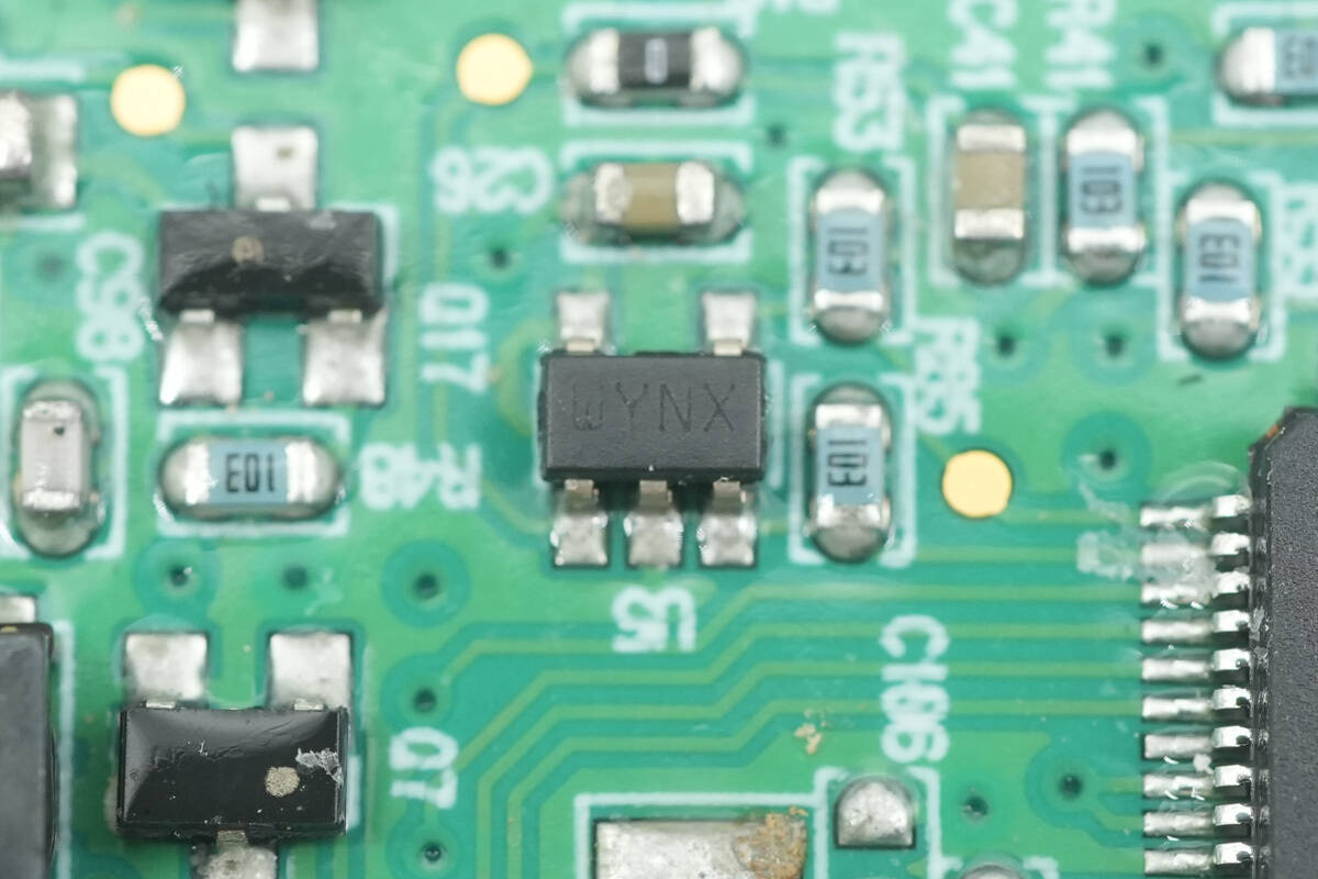
The watchdog chip is from STMicro, marked WYNX, model STWD100YNXWY3F. It is an automotive-grade component, supporting an operating temperature range of -40 to 125°C, and comes in an SOT23-5 package.
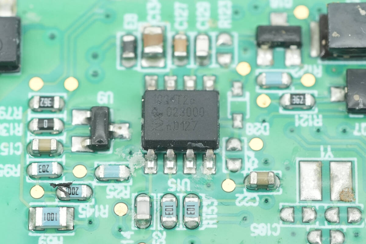
Close-up of the NXP chip marked 1004T2C.
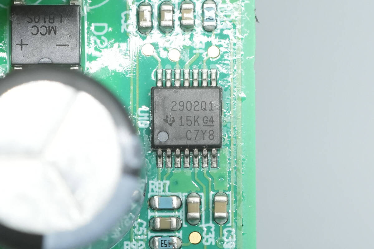
The operational amplifier is from TI, model LM2902-Q1. It is a widely used quad op-amp suitable for automotive applications, compliant with the AEC-Q100 standard, and comes in a TSSOP14 package.
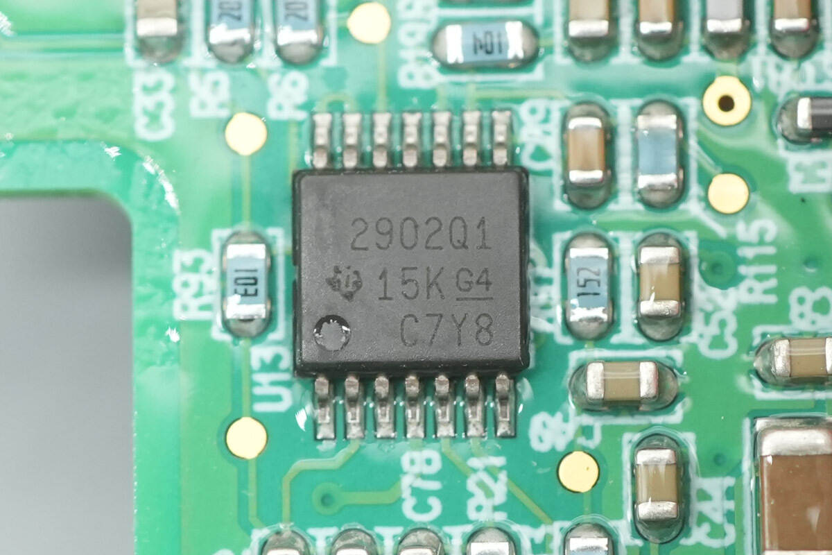
The other operational amplifier has the same model, LM2902-Q1.
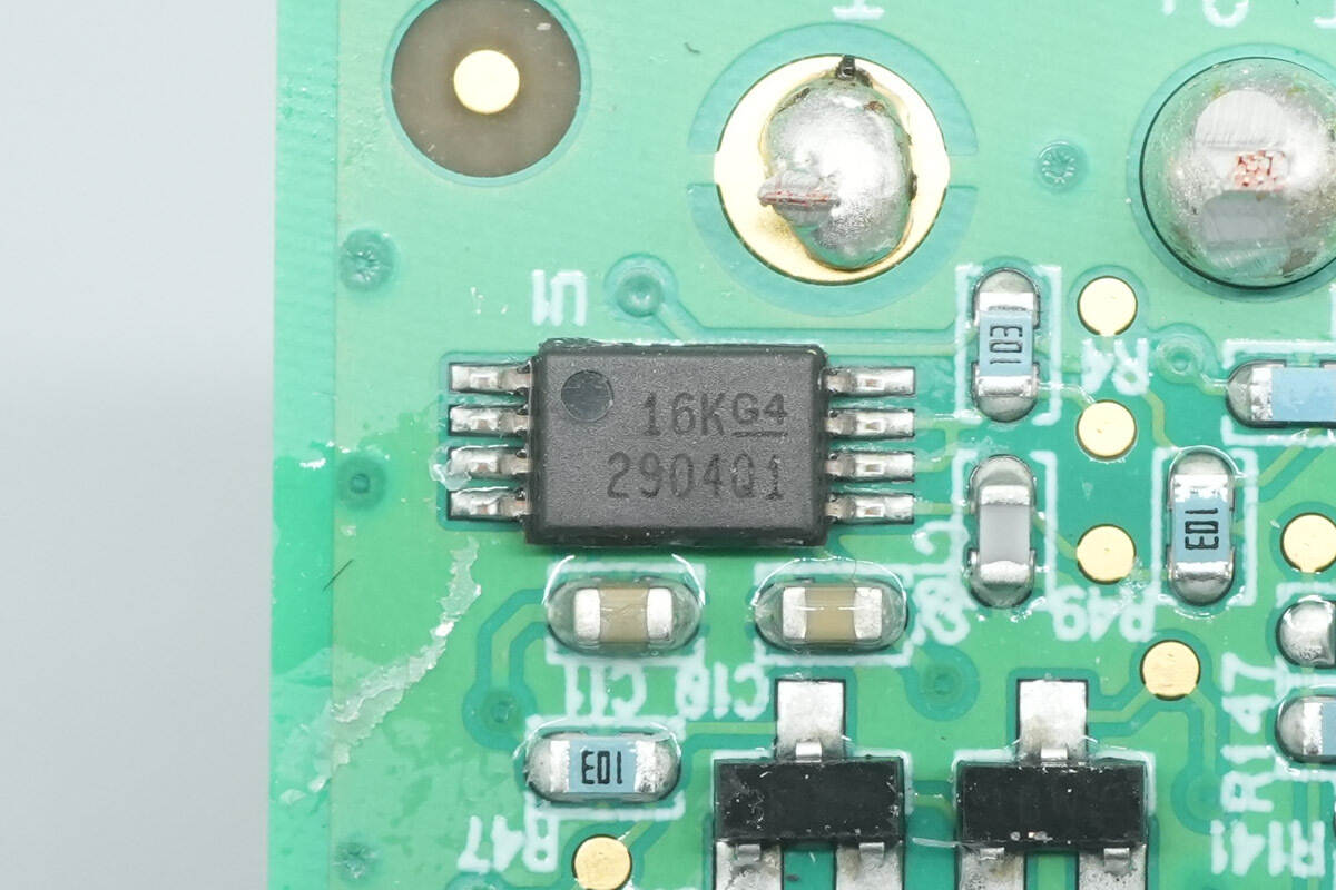
The operational amplifier is from TI, model LM2904-Q1. It is a widely used dual op-amp suitable for automotive applications, compliant with the AEC-Q100 standard, and comes in a TSSOP8 package.
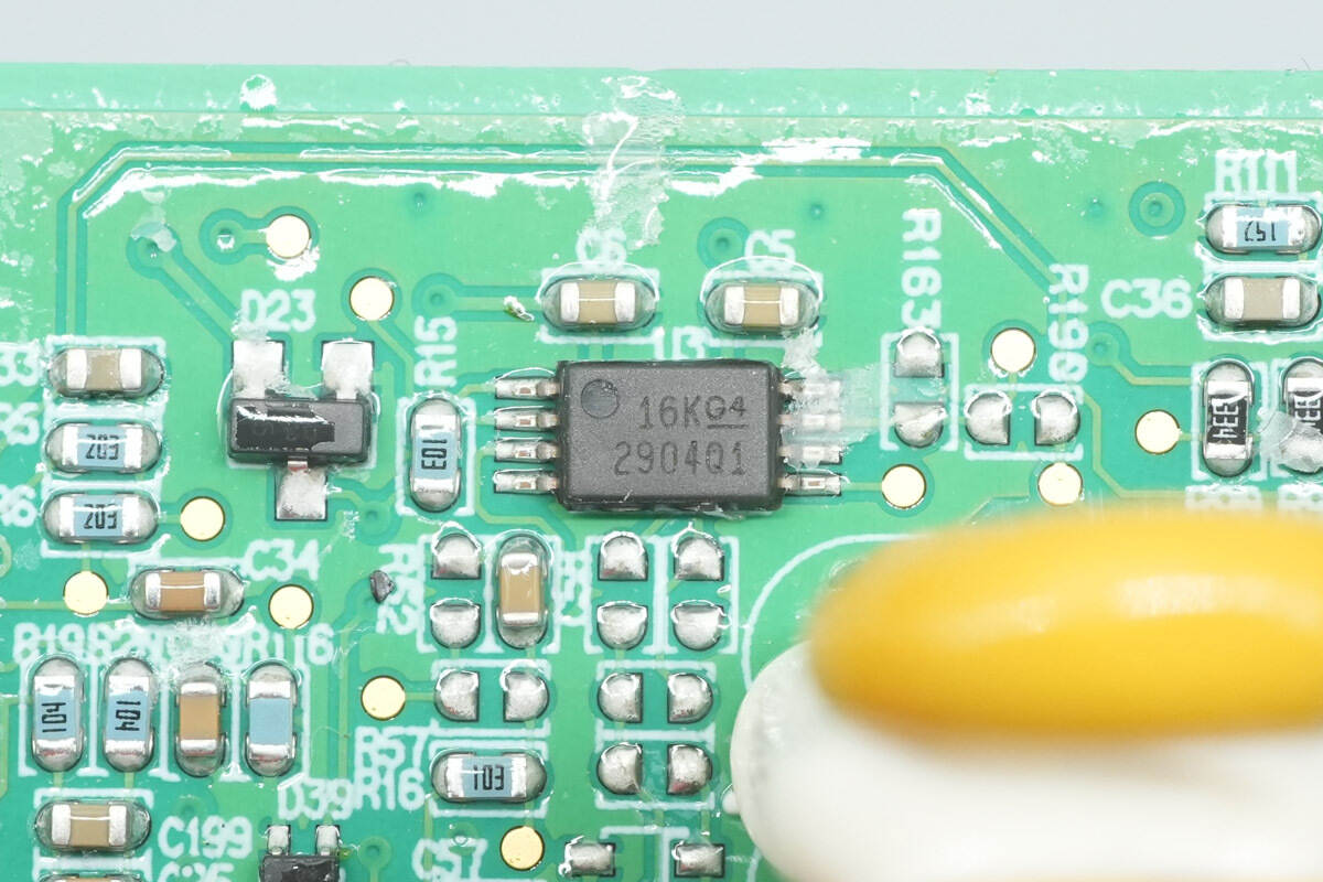
The other operational amplifier has the same model.
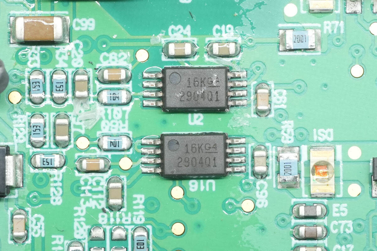
There are a total of four operational amplifiers of the same model.
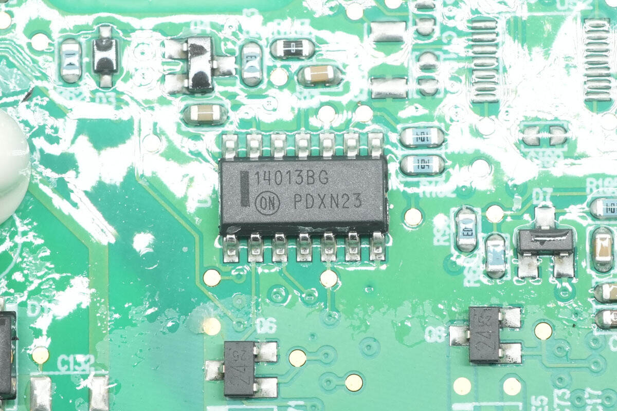
The flip-flop is from onsemi, model MC14013BDG. It is a dual D-type flip-flop and comes in an SOIC-14 package.
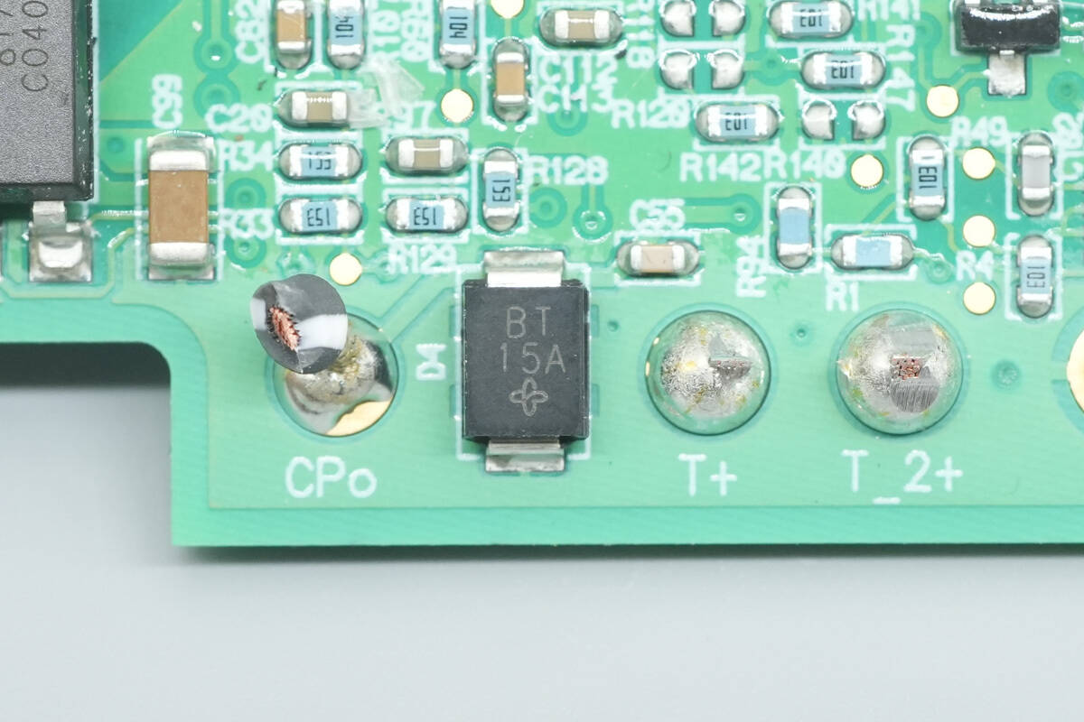
The TVS diode is from Vishay, marked BT, model SMBJ18CA. It is a bidirectional TVS with a clamping voltage of 18 V and comes in an SMB package.
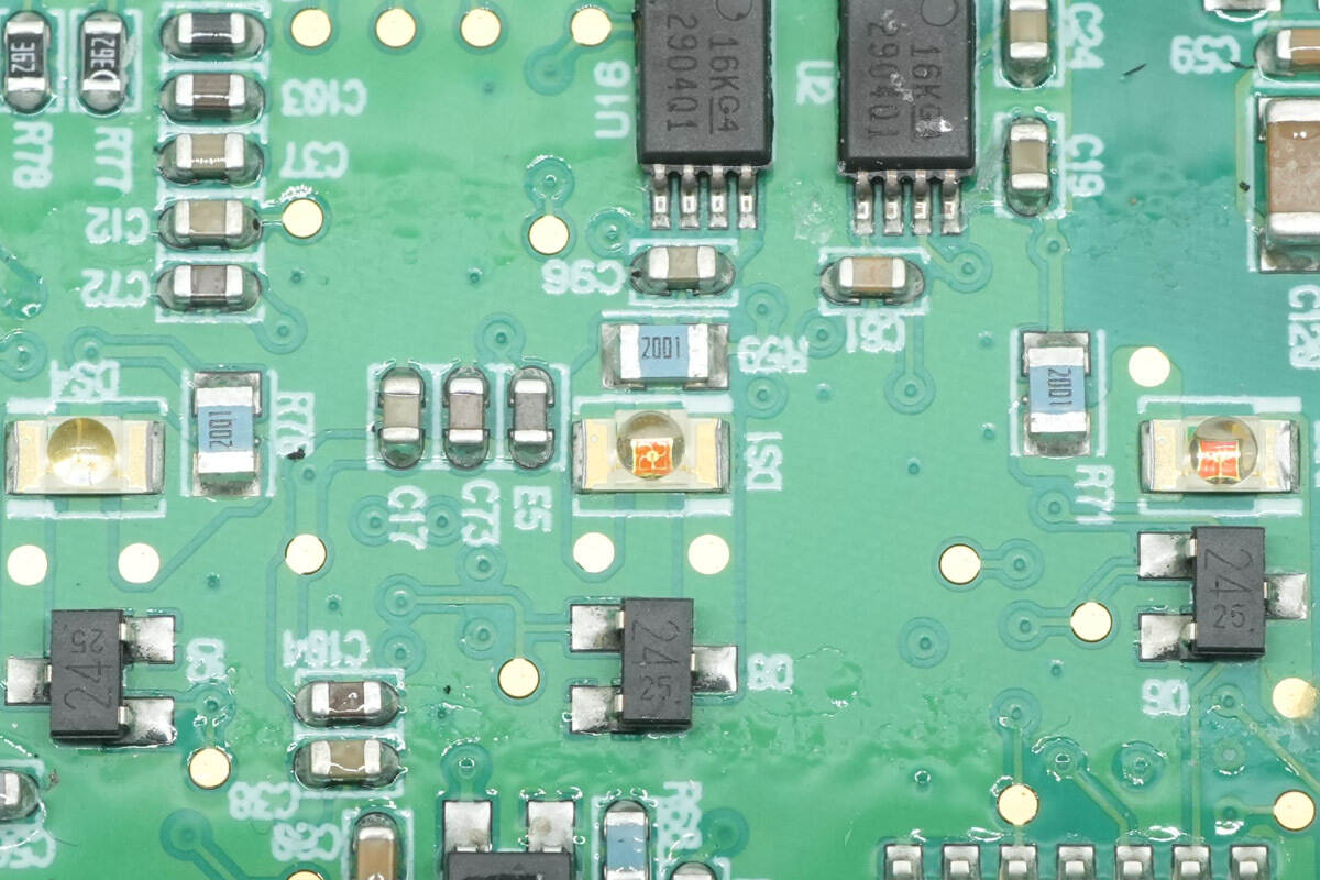
The SMD LEDs are used for status indication.
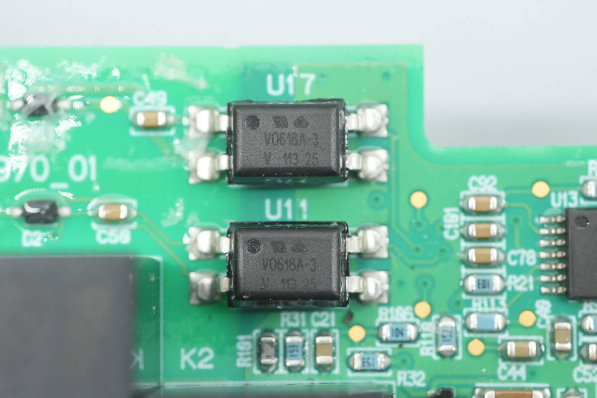
The optocouplers are from Vishay, model VO618A-3, and are used for voltage signal detection.
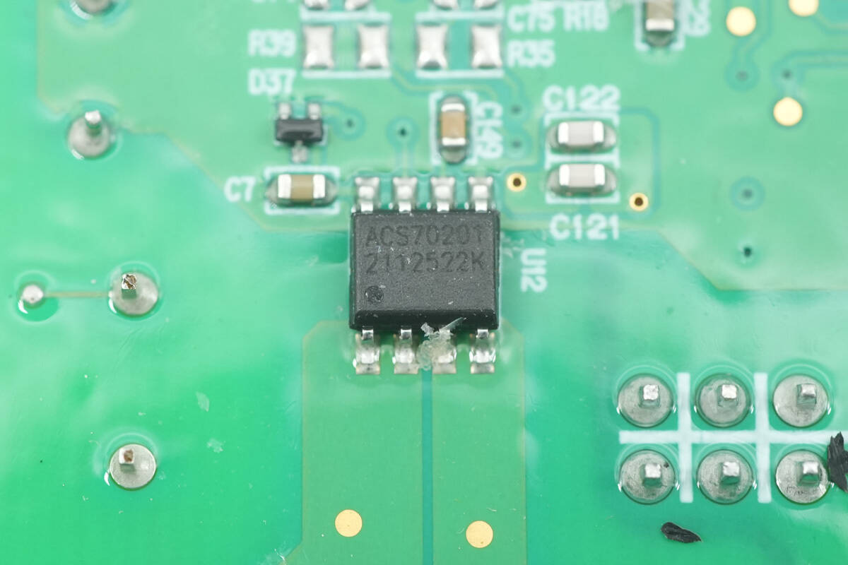
The Hall-effect current sensor is from Allegro, model ACS70201, and comes in an SOP8 package.
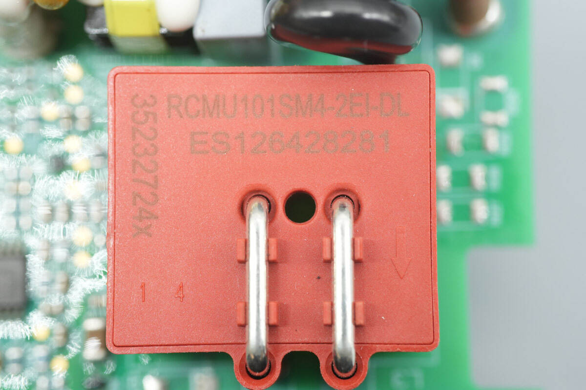
The current sensor features a red housing.
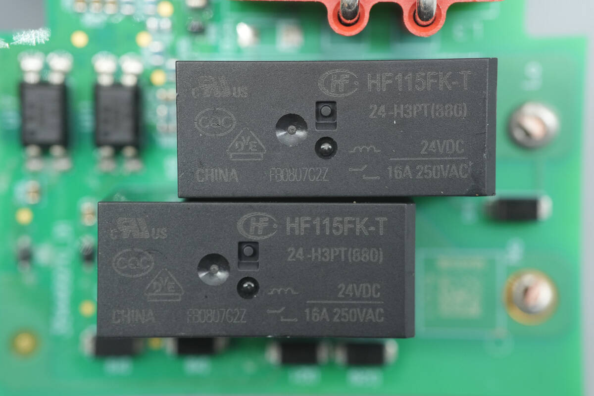
The relays are from Hongfa, model HF115FK-T/24-H3PT. They are compact high-power relays with a single normally open contact, a contact rating of 16 A at 250 VAC, and a coil voltage of 24 V.
A thermistor is installed inside the power plug to monitor temperature.
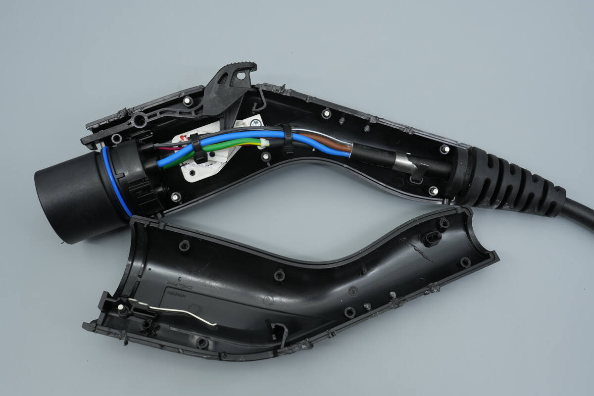
Disassemble the charging connector housing.
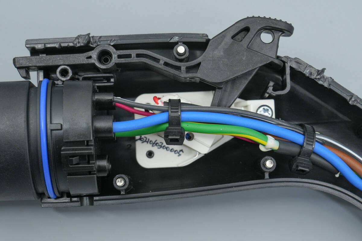
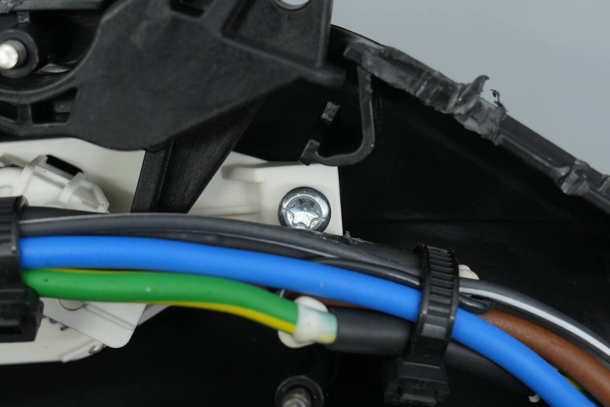
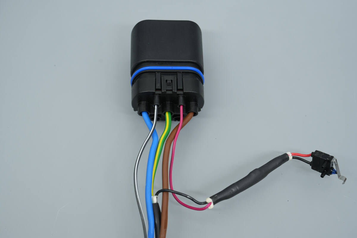
The internal wires are secured with cable ties, and the micro switch is secured with a plastic plate.
The plastic sheet is fixed with screws.
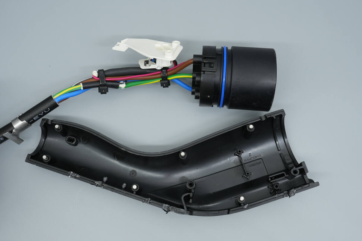
Remove the charging connector from the housing.
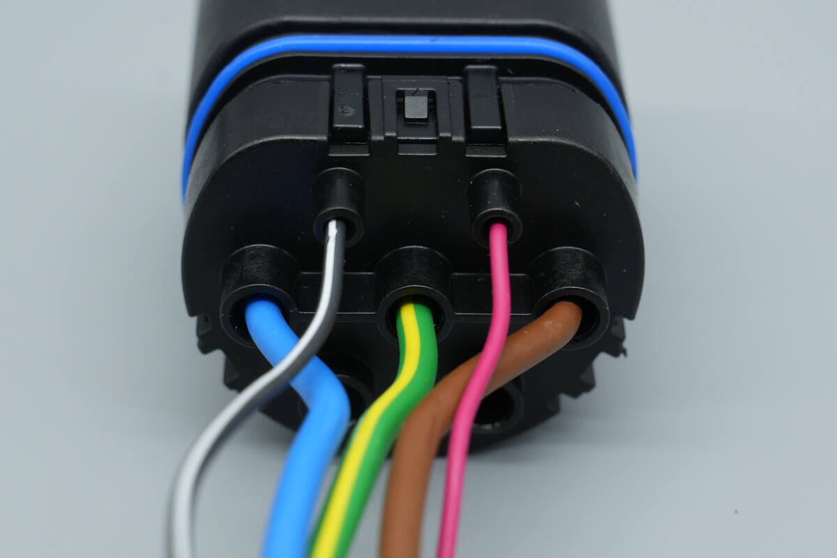
The charging connector has a blue sealing ring.
The housing is secured with snap-fit fasteners.
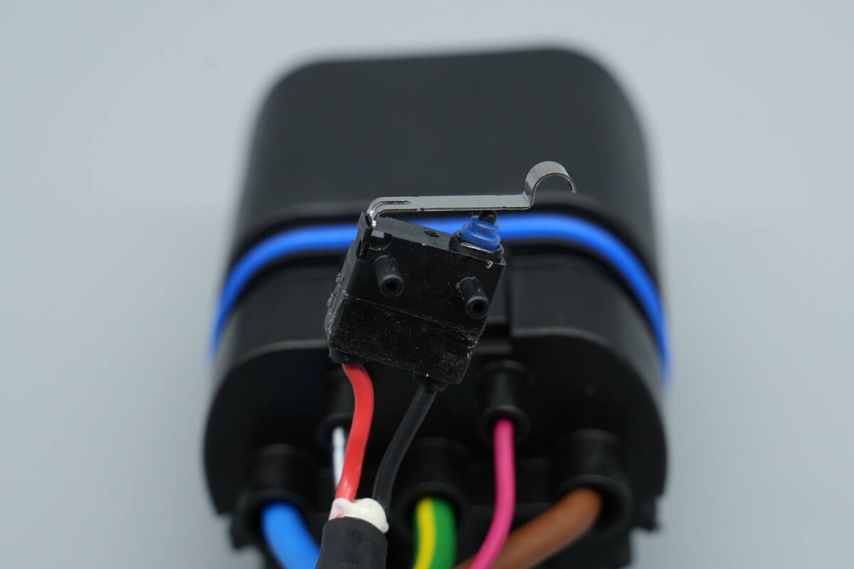
A close-up of a microswitch used to detect connection to the correct position.

Well, those are all components of the Lincoln 1760W Portable EV Charger.
Summary of ChargerLAB
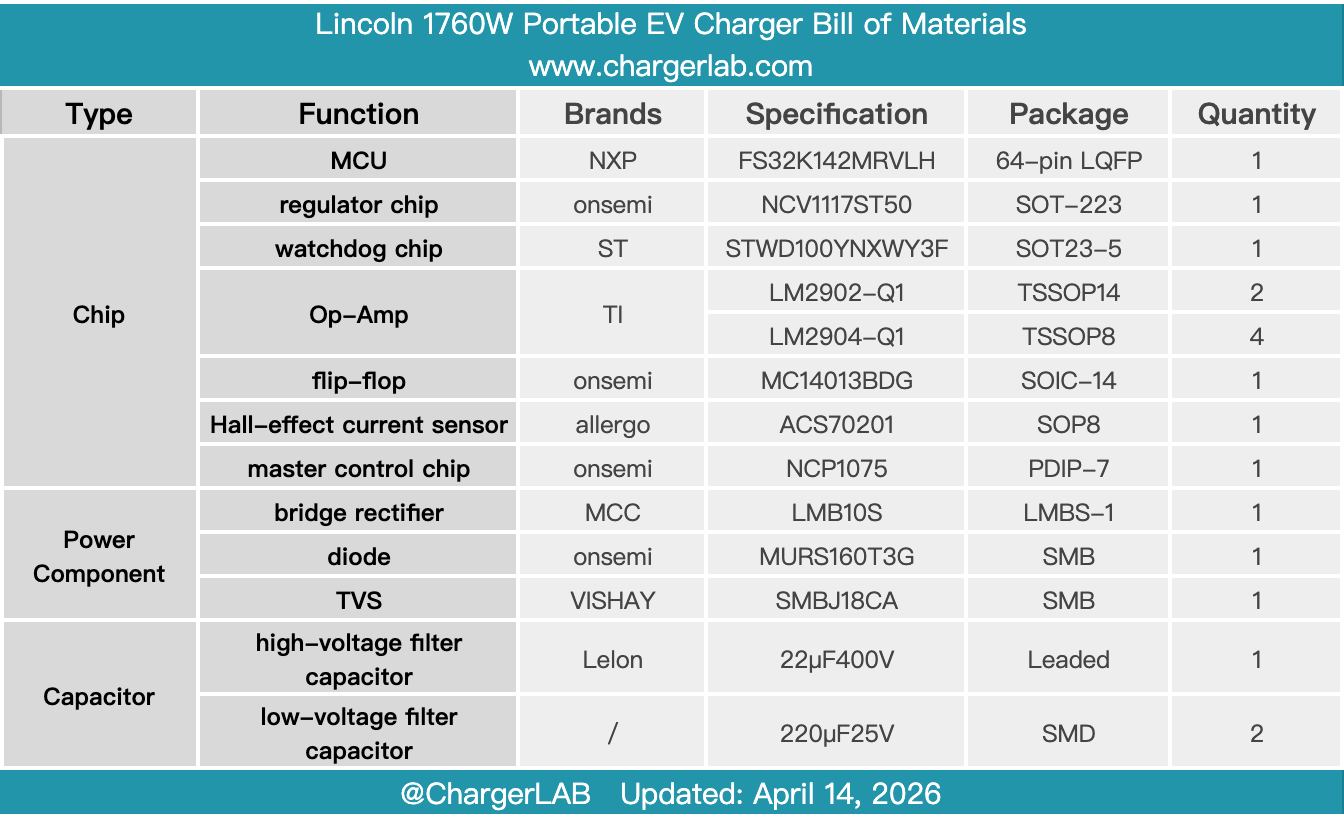
Here is the component list of the Lincoln 1760W Portable EV Charger for your convenience.
The Lincoln 1760W Portable EV Charger features a split design with a 10A plug, supports an 8A charging current, and delivers 1760W of charging power. It is approximately 6.6 meters long. It offers charging protection, leakage protection, and a charging status display, and comes with a carrying case for easy portability in the vehicle.
After taking it apart, we found that the PCBA module is fixed with screws. The control box uses an NXP FS32K142MRVLH MCU, along with TI LM2902 and LM2904 operational amplifiers, for parameter acquisition and protection control.
The power supply chip uses the Onsemi NCP1075, and the NCV1117ST50 is used to regulate the power supply for the MCU. A current transformer and a Hall effect current sensor are included for AC and DC leakage current acquisition. The control box features a sealed design to effectively protect the PCBA module, and an internal thermistor in the connector provides temperature detection to ensure safe operation.
Related Articles:
1. Teardown of Yoobao LY45 20000mAh 45W Power Bank (Built-in Dual Cable)
2. Teardown of Polestar 3-Phase AC Charging Cable Extension
3. Teardown of Lotus Three-Phase AC Charger Extension Cord