Introduction
The Honor LCHSE Clip-On Earphone 2 Pro features the titanium arch bridge 2.0 design. It offers a 10-hour battery life on a single charge, and with the charging case, it supports an impressive total playtime of 44 hours. The charging case is equipped with wireless charging functionality. Inside, it houses a 12mm dual-magnetic dynamic driver with an LCP (Liquid Crystal Polymer) diaphragm, and it also includes a wear detection feature. Next, let’s take a closer look at its internal components and design.
Product Appearance

The front of the packaging box features the "LCHSE Clip-On Earphone 2 Pro" label along with an image of the earphones.

The back of the packaging displays the key selling points and product information.
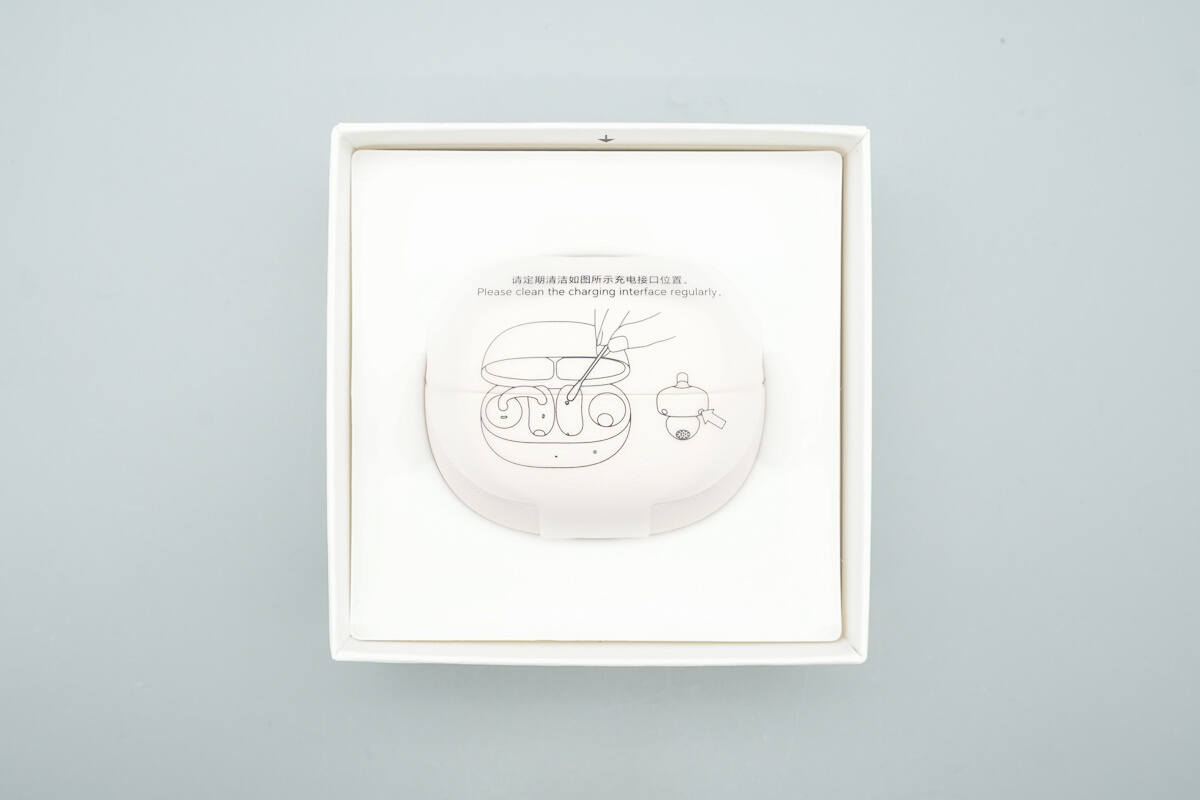
The charging case of the earphones is attached with anti-scratch paper.
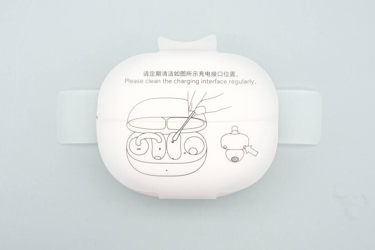
The sticker indicates the contact points on the charging case.
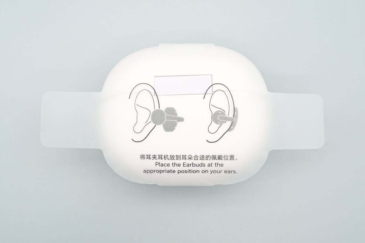
The other side of the sticker shows the correct way to wear the earphones.
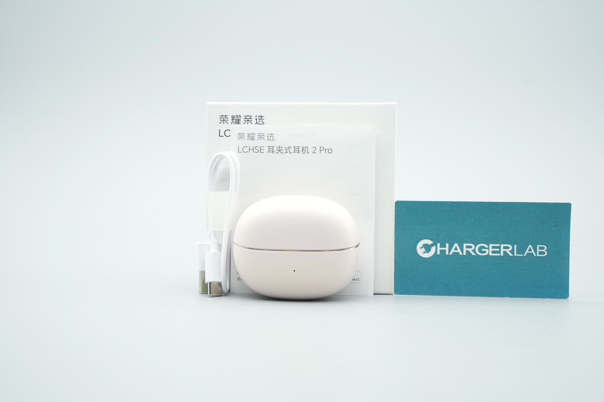
The package includes the earphones, a charging cable, and a user manual.
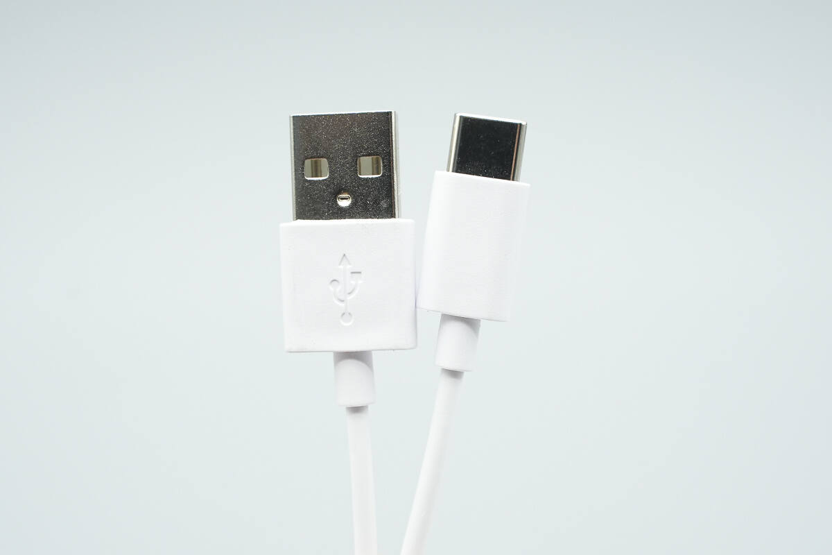
The charging cable is a USB-A to USB-C type.

The length of the cable is about 32 cm (12.6 inches).
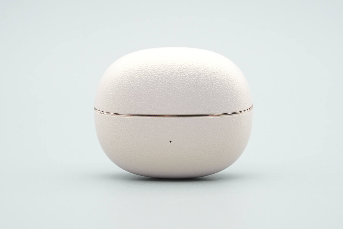
The charging case is oval-shaped, with a gold trim along the seam of the shell.
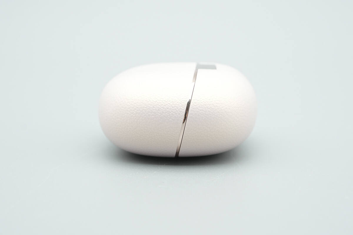
The gold trim extends to the side of the charging case.
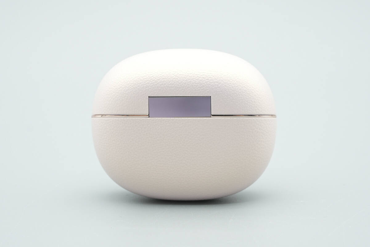
The back of the charging case features a shiny silver hinge.
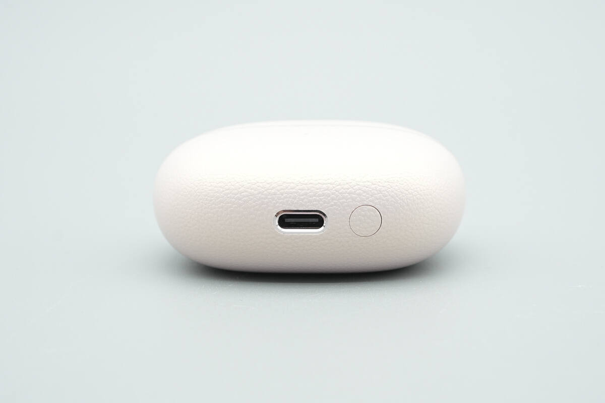
The bottom of the charging case has a USB-C port and a Bluetooth pairing button.
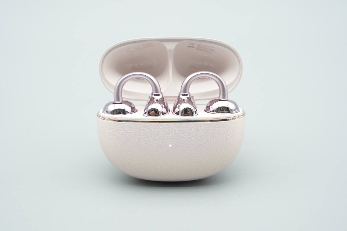
The earphones are securely held in place by magnets, making it easy to store and retrieve.
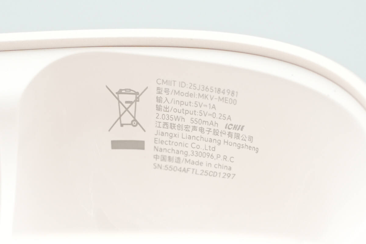
Model: MKV-ME00
Input: 5V⎓1A
Output: 5V⎓0.25A
2.035Wh 550mAh
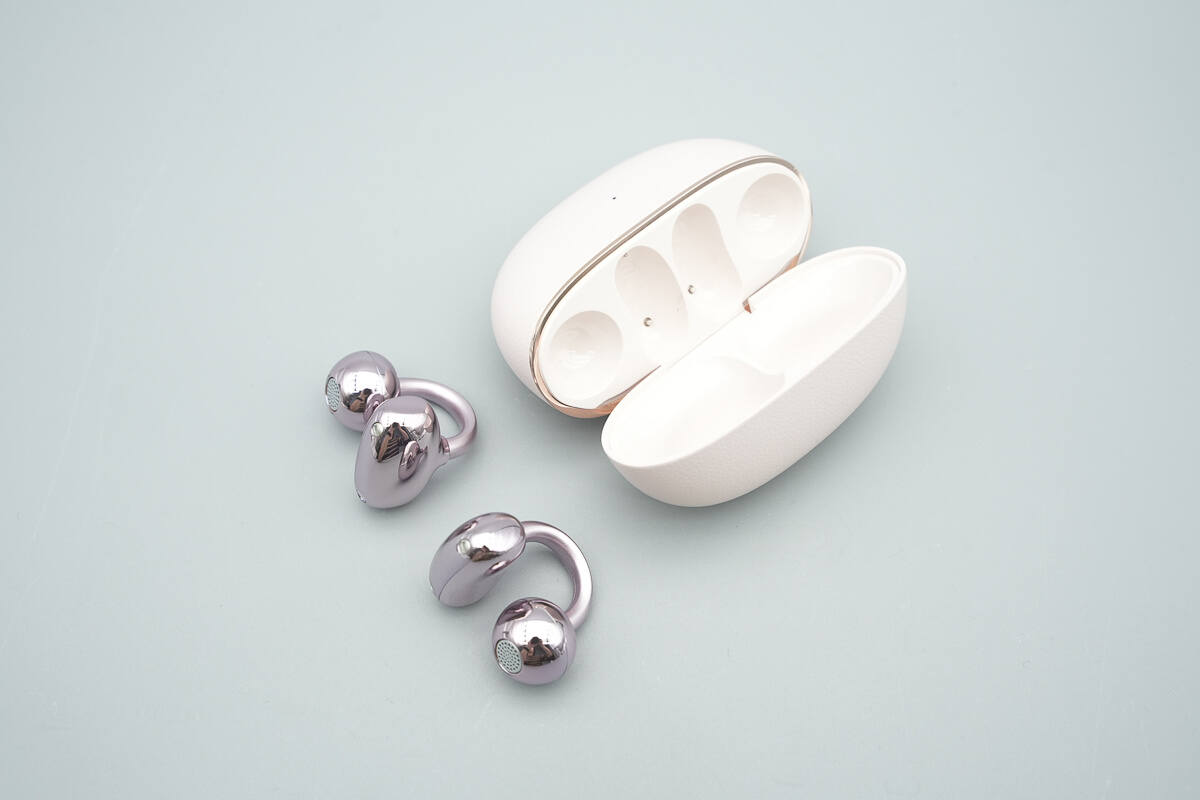
Remove the earphones from the charging case.
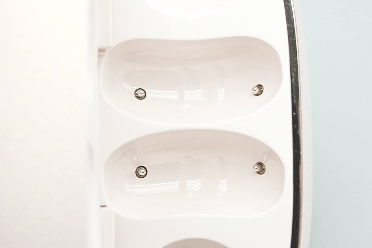
Close-up of the charging contacts.
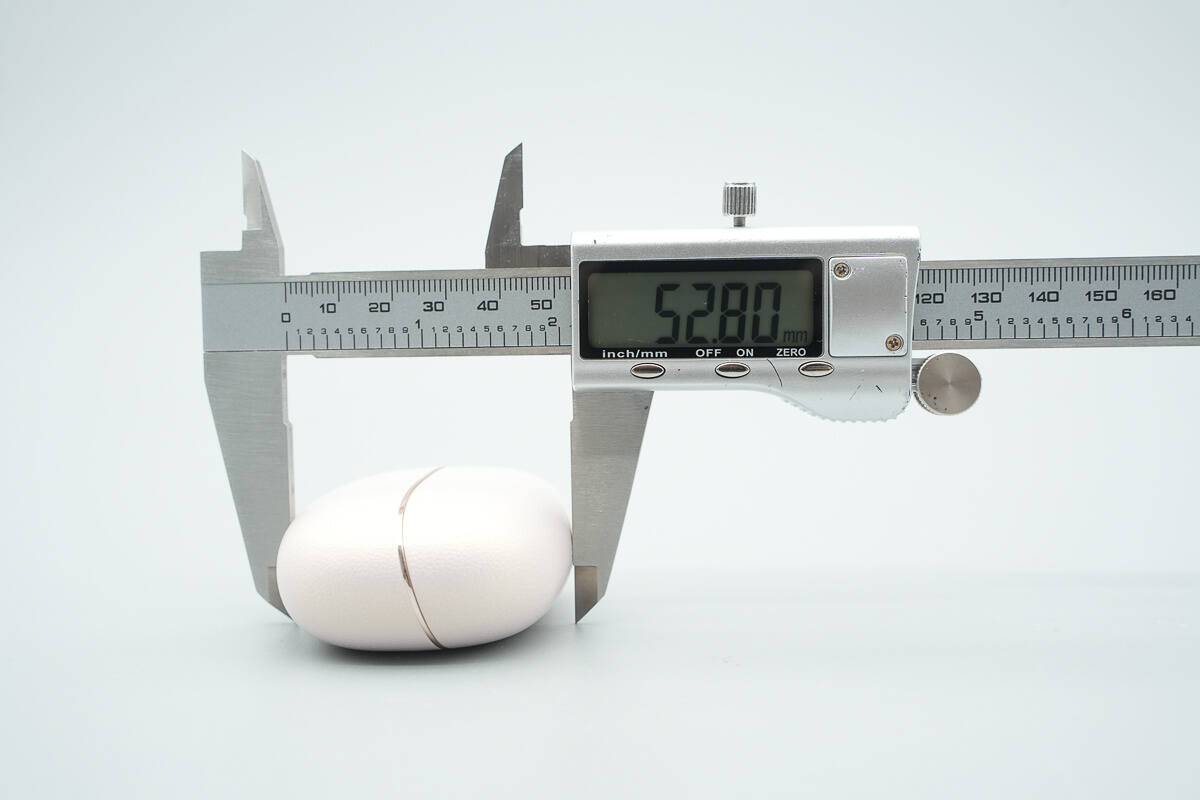
The height of the case is about 52.8 mm (2.079 inches).
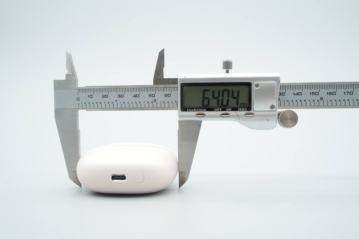
The width is about 64 mm (2.52 inches).
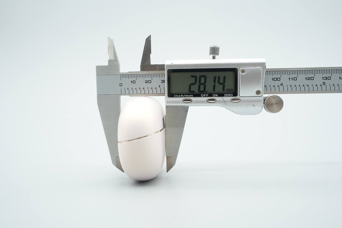
The thickness is about 28.1 mm (1.11 inches).
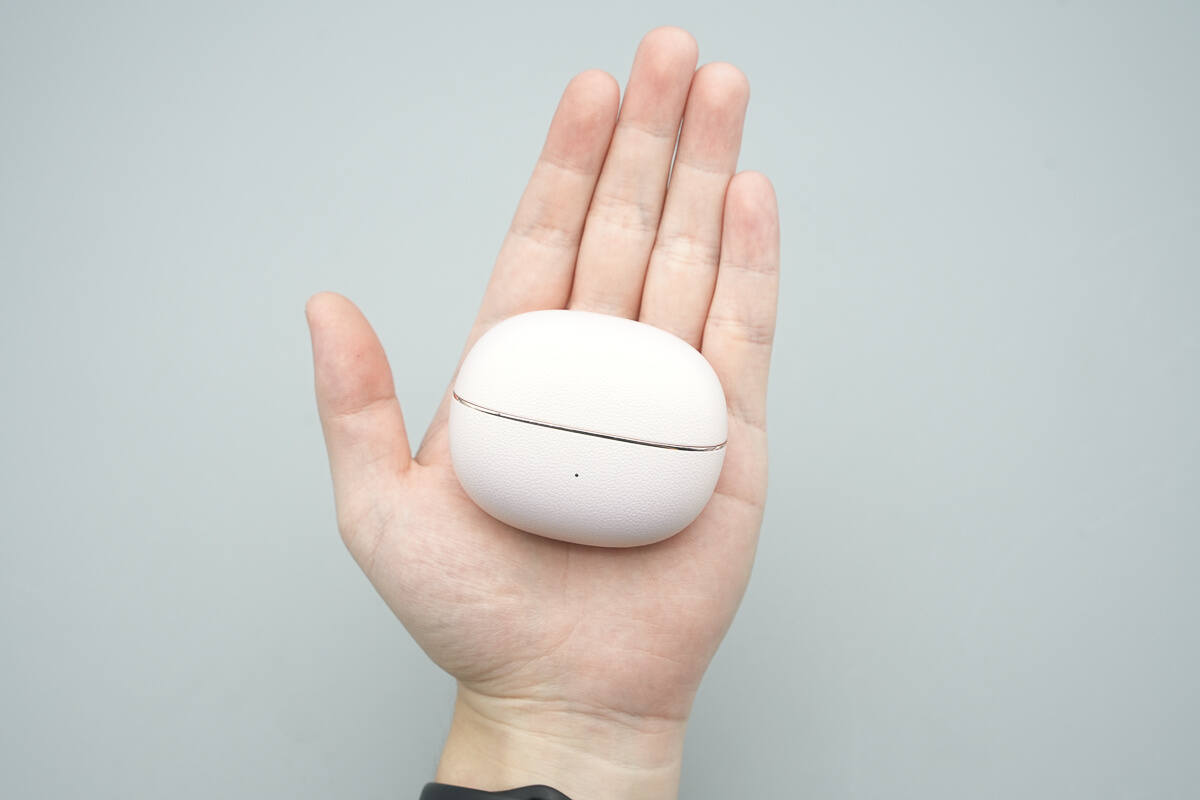
That's how big it is on the hand.
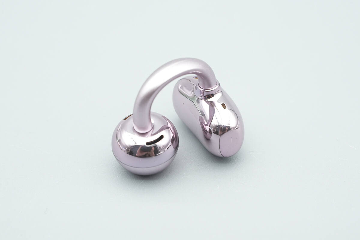
The earphones have a glossy surface with a smooth and rounded design.
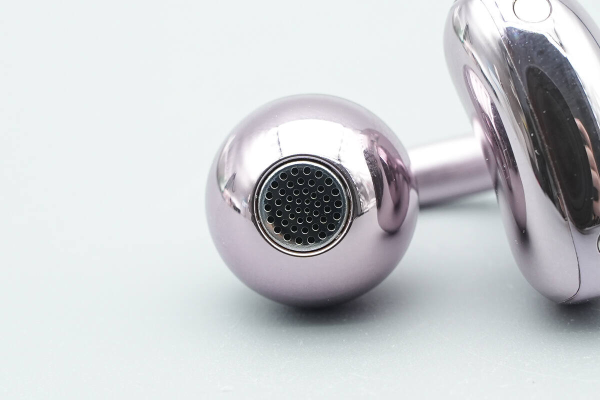
The sound outlet is protected by a metal cover.
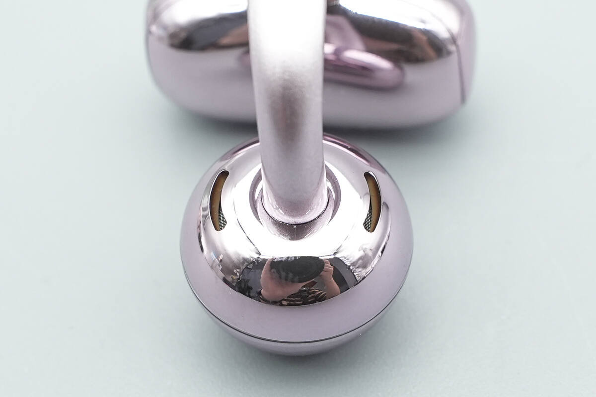
The rear side features inverse sound outlets.

The rear part of the cavity has microphone pickup holes.

The bottom features charging contacts.
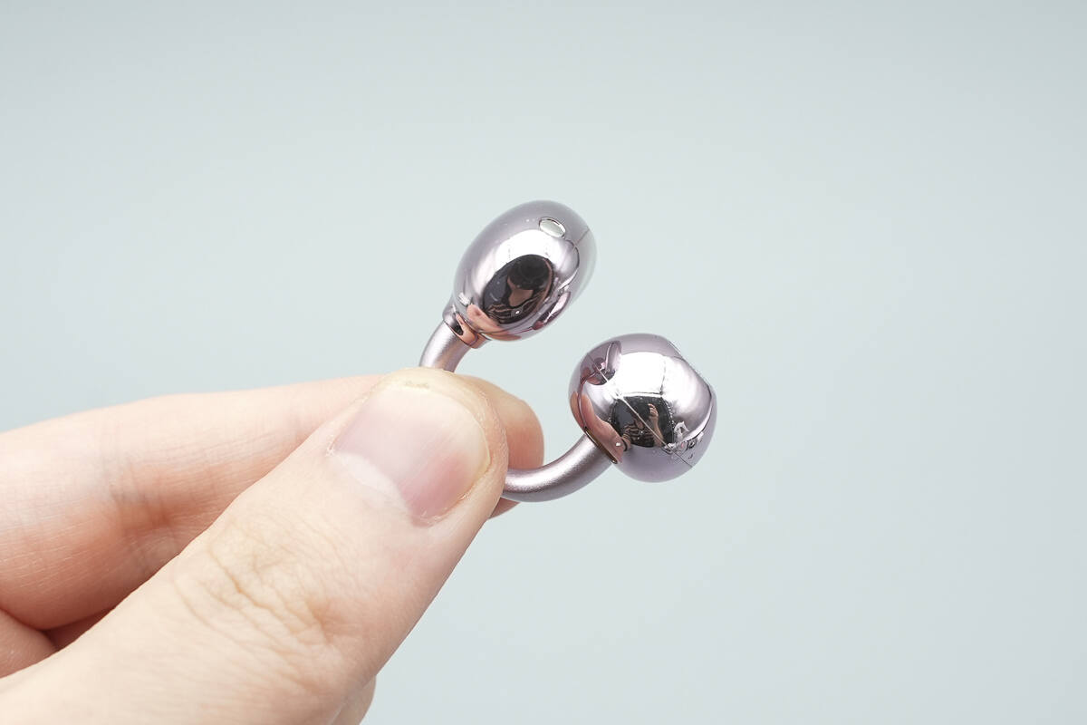
The size of the earphones gives an intuitive feel when held in the hand.
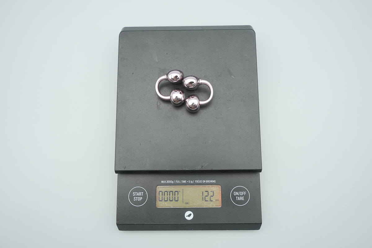
The weight is about 12.2 g (0.43 oz).
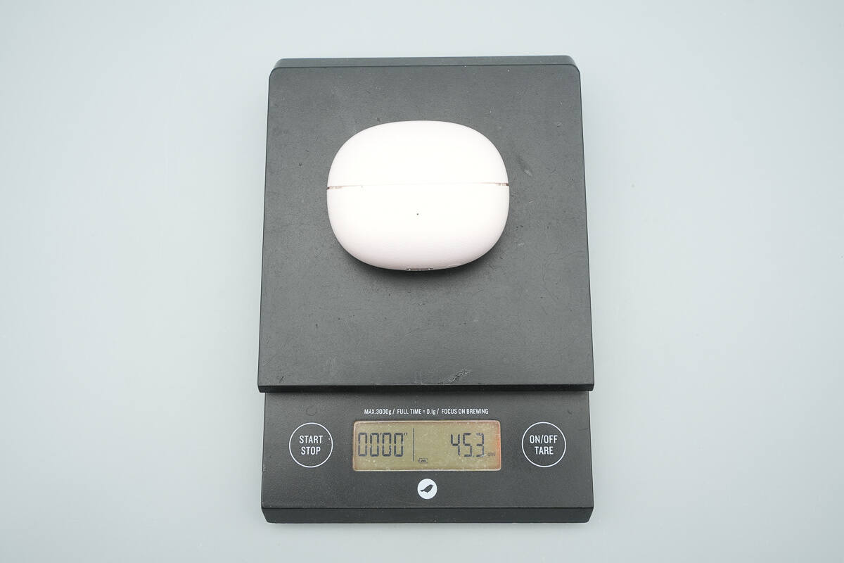
The weight of the case is about 45.3 g (1.6 oz).
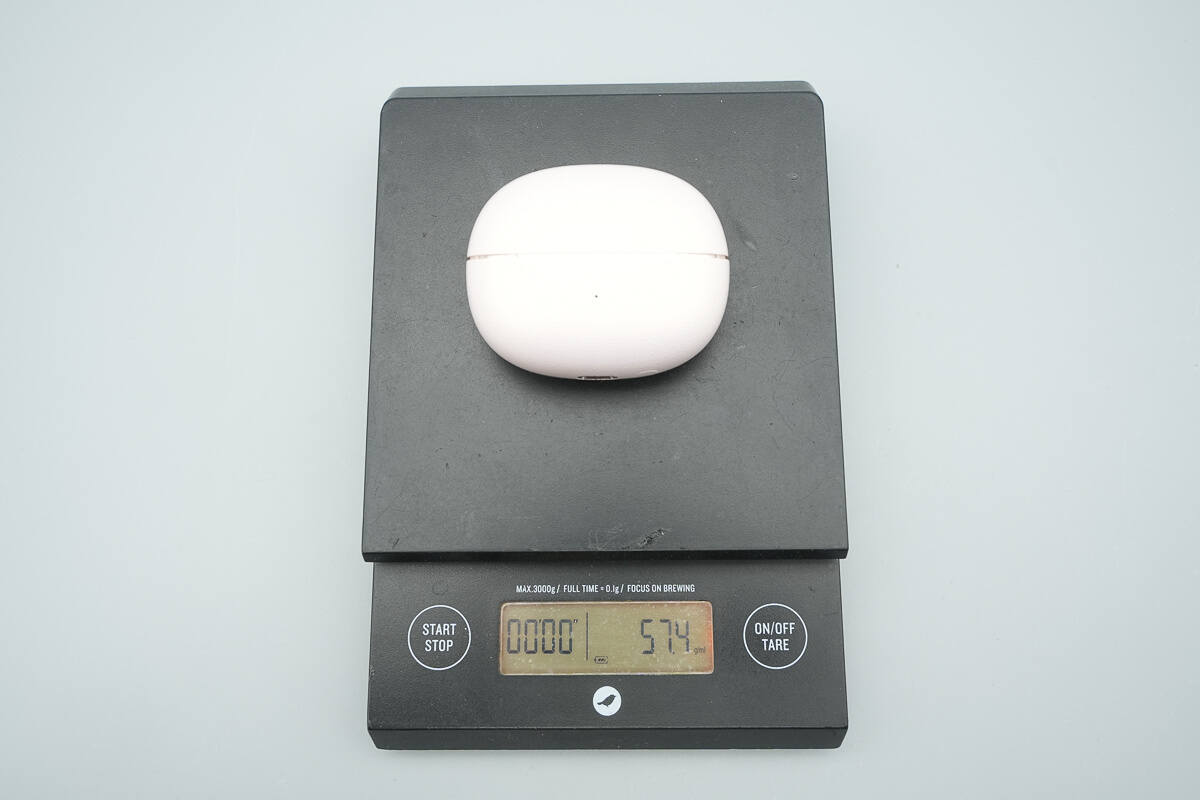
The weight of the earphones and charging case combined is about 57.4g (2.02 oz).
Teardown
Next, let's take it apart to see its internal components and structure.
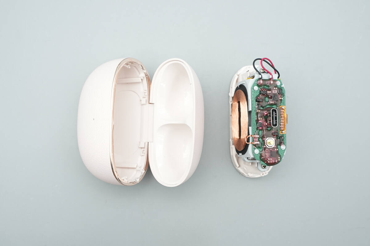
Open the charging case along the seam.
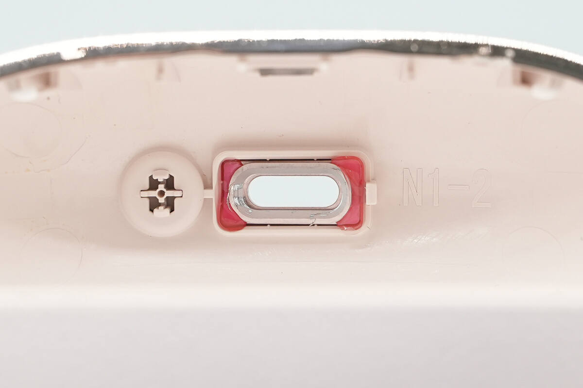
Close-up of the button and charging port.
The PCBA module is coated with red adhesive. The module is secured to the plastic bracket through hot-melt bonding, and the plastic bracket is fixed to the casing with screws.
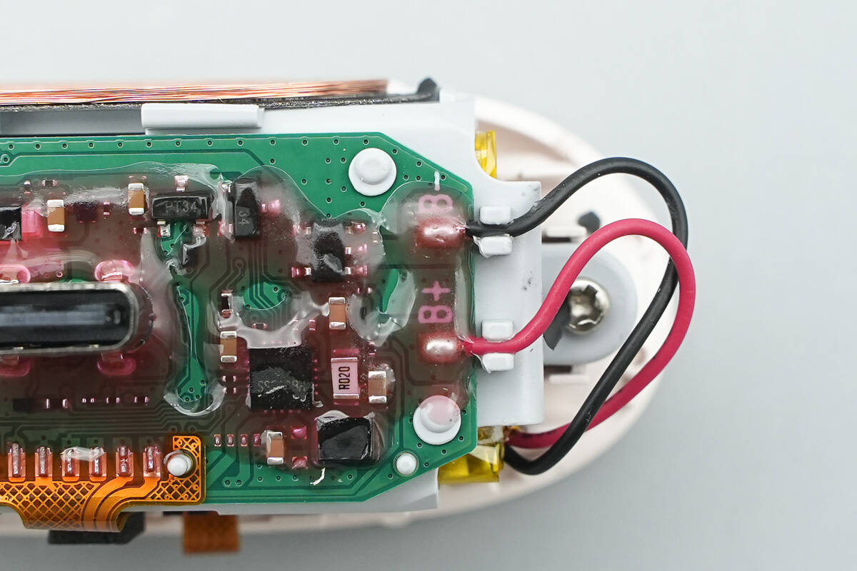
The battery wires are connected through soldering, with the solder joints reinforced by adhesive.
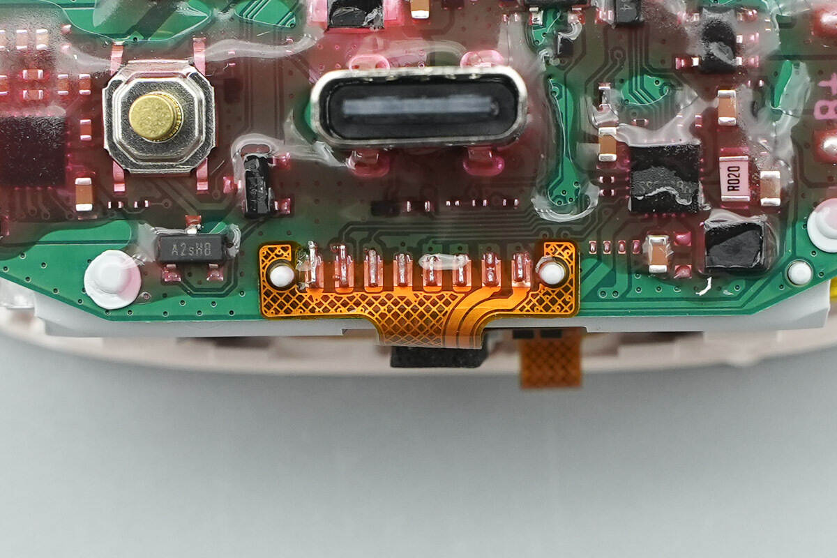
The flex cable is connected through soldering.
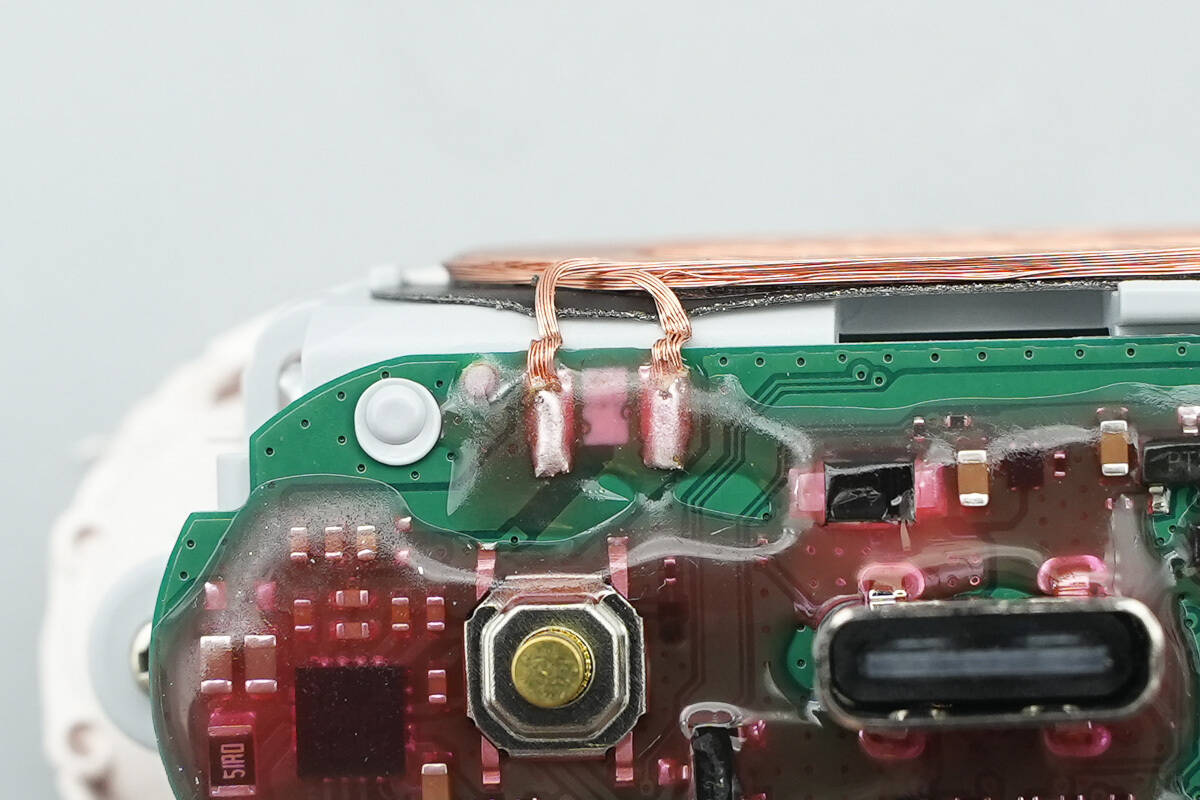
The wireless charging coil is connected through soldering.

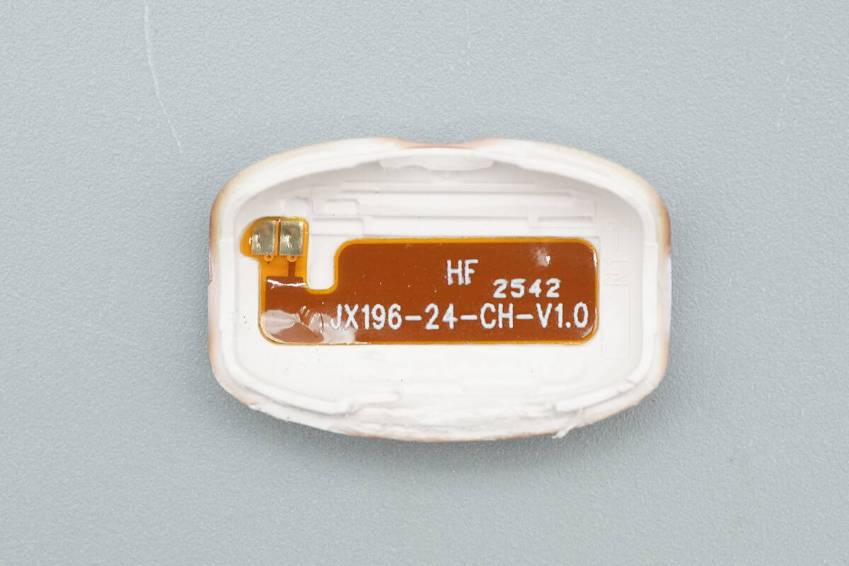
One side of the bracket features an indicator light and the flex cable for the Hall sensor.
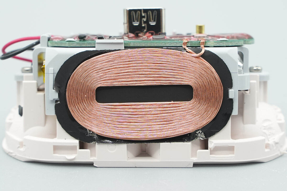
The other side features the wireless charging coil.

Unscrew the screws and remove the battery bracket.
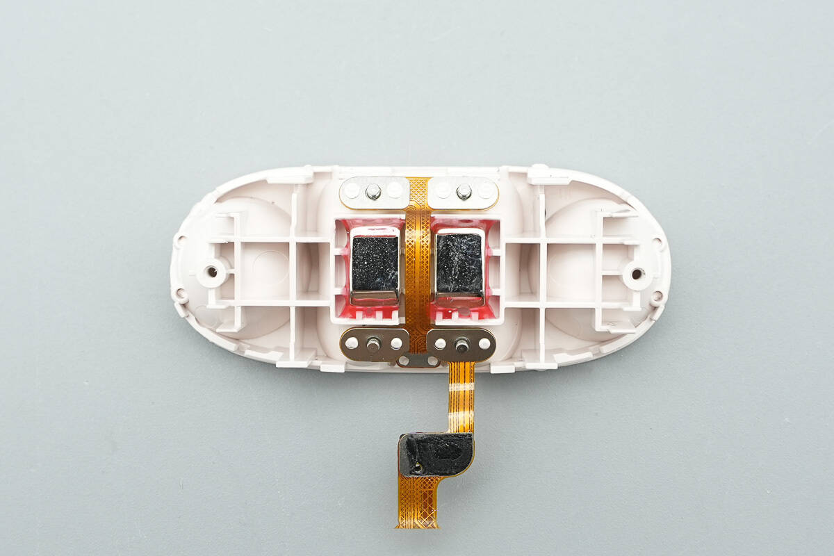
The interior of the casing contains magnets and charging contacts.
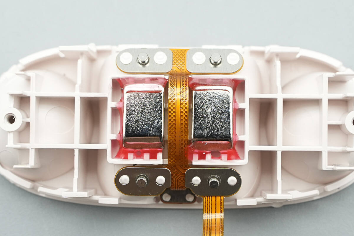
The magnets are fixed with adhesive, while the charging contacts are secured using hot-melt pillars.

The red and white LED indicator lights are covered with foam for light shielding.

The Hall sensor, marked with "qH," is used to detect the opening and closing of the charging case.

The battery is fixed inside the bracket with adhesive. It is sourced from YD, with the model number YD651841. The charging limit voltage is 4.2V, the nominal voltage is 3.7V, and it has a capacity of 550mAh and an energy of 2.035Wh. The battery has passed the CCC certification.
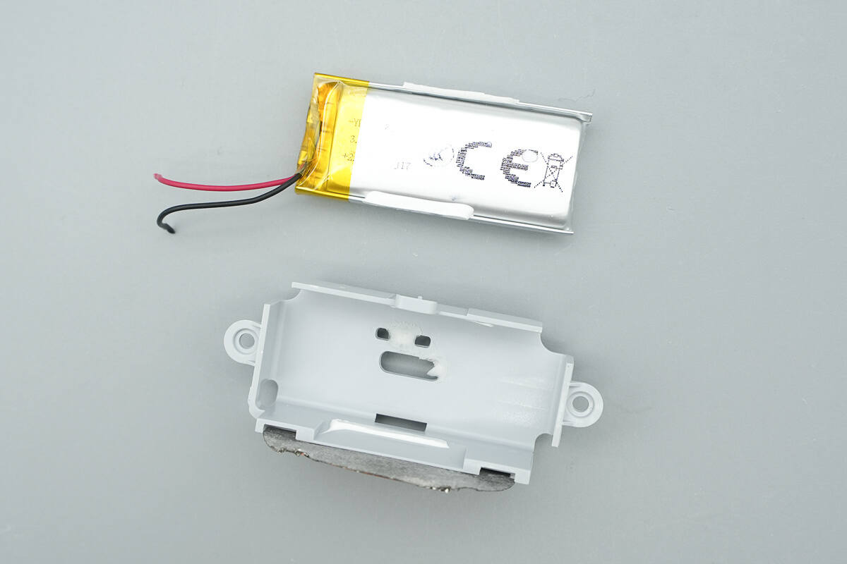
Remove the battery.
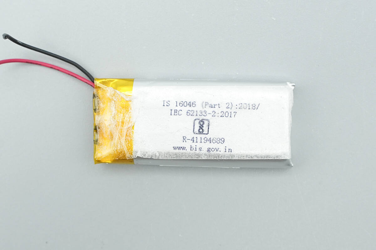
It has also passed the Indian BIS certification.
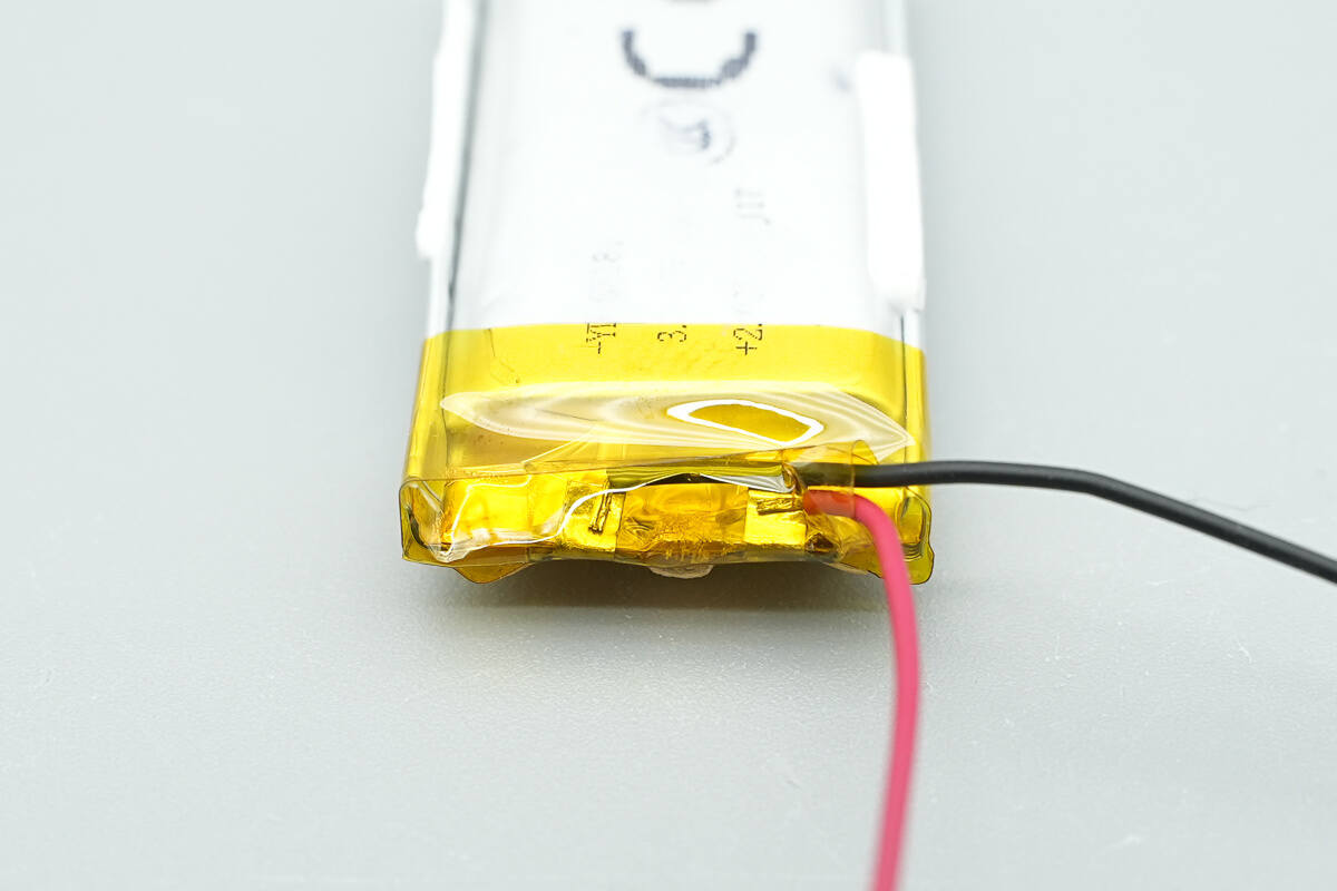
High-temperature adhesive tape is applied to the positive and negative terminal tabs for insulation.
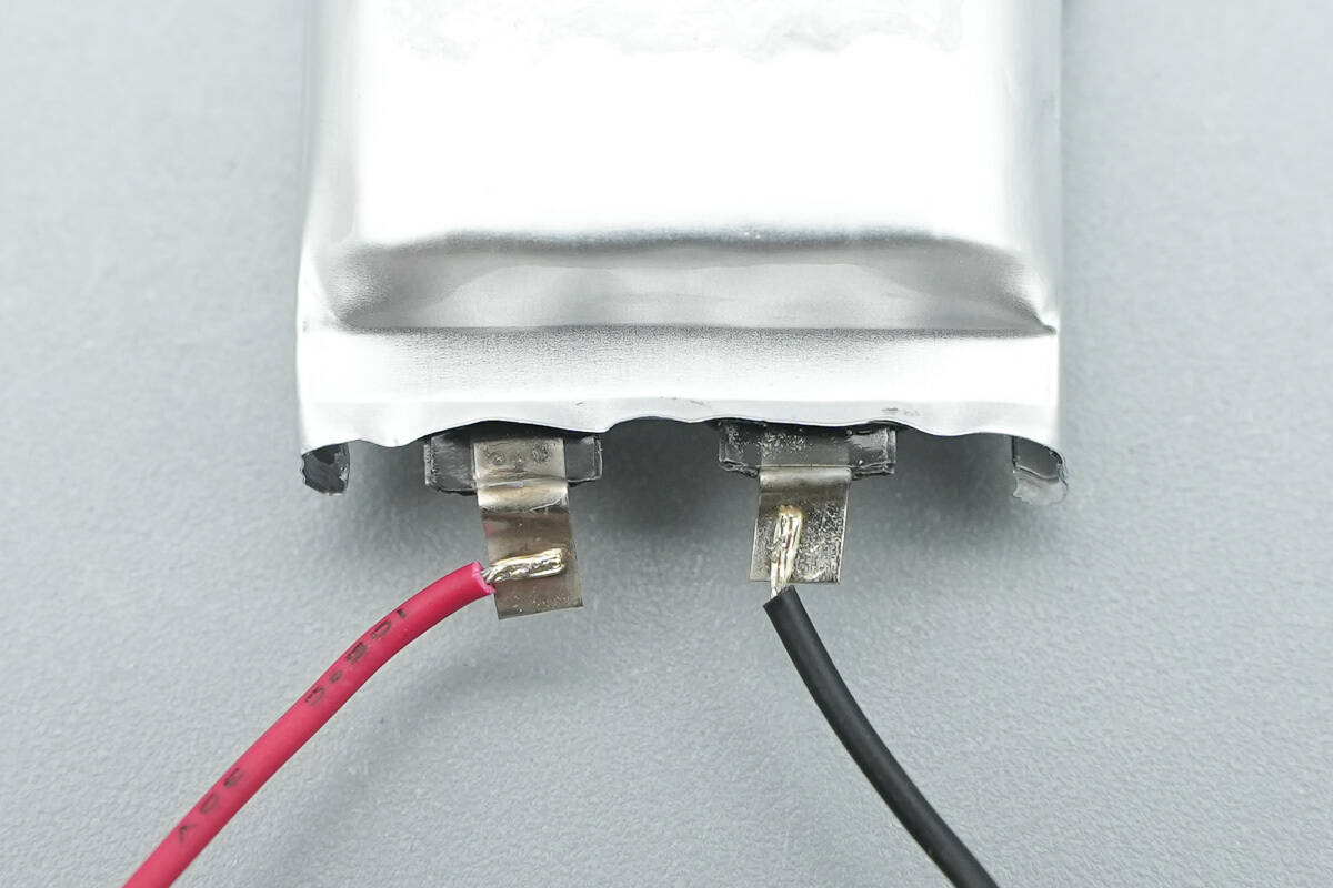
The positive and negative terminals are soldered through wires.
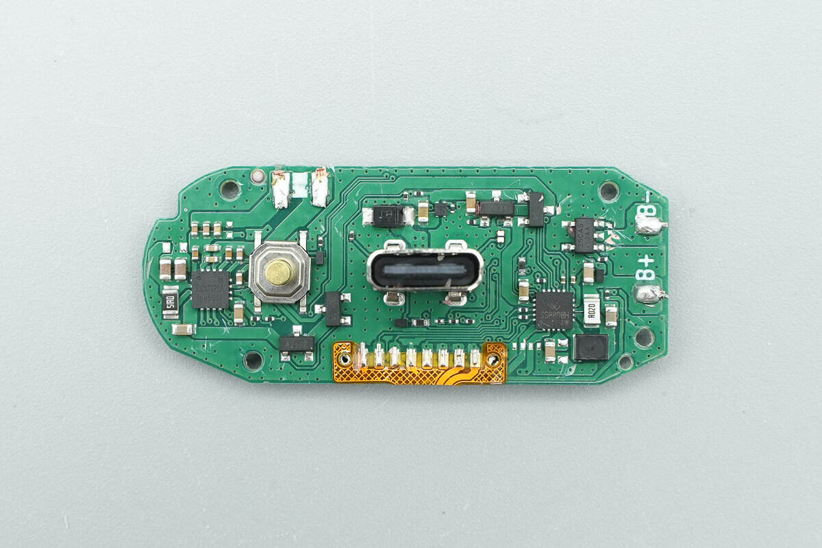
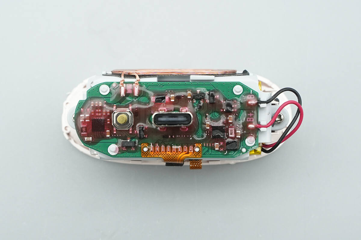
The front of the PCBA module features a wireless charging receiver chip, USB-C socket, battery protection chip, and power management chip.
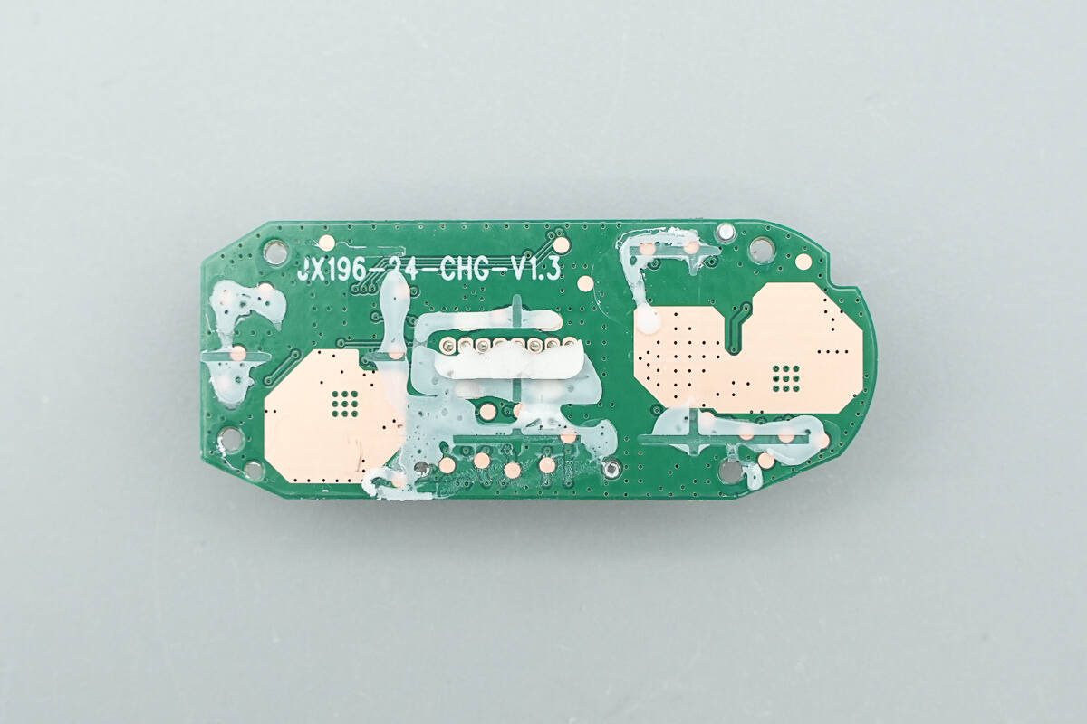
The back of the PCBA module exposes copper to reinforce heat dissipation at the locations corresponding to the chips.
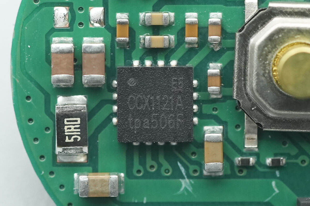
The wireless charging receiver chip, sourced from OCS and marked with CCX1121A and model OPS1121A, is a high-efficiency chip that complies with the Qi 1.2.4 standard. It integrates a full-bridge rectifier for wireless reception, a low-dropout linear voltage regulator, a Qi wireless charging protocol, and a wired switch path. The chip is packaged in a QFN3030-16L format, with a minimal number of external components and no need for firmware programming, enabling a highly integrated wireless charging receiver design.
The OPS1121A typically outputs 5V with a maximum output current of 800mA. It supports dynamic adjustment of the rectifier's output voltage, delivering excellent dynamic switching response and full-load efficiency. It also has built-in memory and supports I2C interfaces for program upgrades, debugging, and control. The chip integrates a wired switch path to allow seamless switching between wired and wireless power based on the power source, and it includes input over-voltage and over-current protection.
The OPS1121A offers multiple protection features, including internal temperature monitoring, external NTC overheat protection, and over-voltage protection during rectification under mobile conditions. It also supports over-current protection, programmable temperature control, and error detection with indication. The chip is certified by the WPC Qi 2.1 BPP protocol and has passed the manufacturer's compatibility tests with hundreds of transmitter models.

Here is the information about OCS OPS1121A.

The battery protection chip is sourced from iCM, marked with 25CAS and model CM1125-CAS. It is a single-cell lithium battery protection IC with integrated MOSFETs. The chip includes high-precision voltage detection circuits and delay circuits. By monitoring the battery's voltage and current, it provides overcharge, over-discharge, and overcurrent protection, making it suitable for single-cell lithium and lithium polymer batteries.
The CM1125-CAS has an overcharge protection voltage of 4.3V, with a 25mV accuracy, and an over-discharge voltage of 2.8V, with a 100mV accuracy. The chip features a built-in 50mΩ MOSFET, with discharge overcurrent detection set at 2A, short-circuit current detection at 3.6A, and charge overcurrent detection at 2A. It also has an integrated delay function and is packaged in an SOT23-5 form factor.
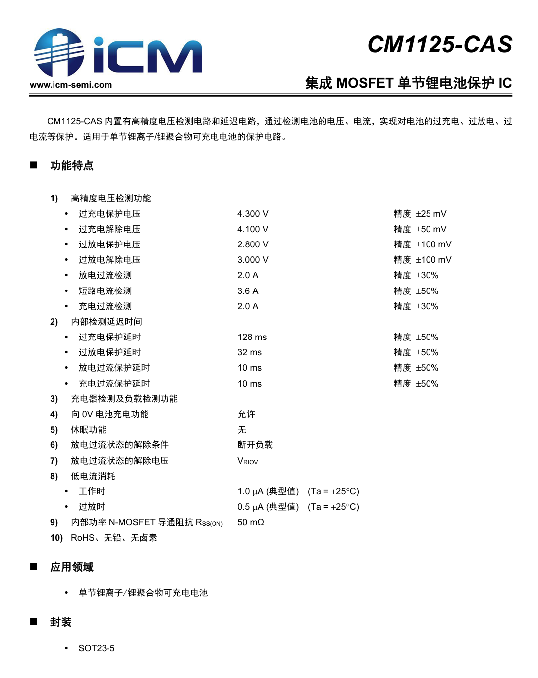
Here is the information about iCM CM1125-CAS.

The power management chip is sourced from SiNH MICRO, model SS88D8H. The chip integrates an 8-bit enhanced MCU with 8KB MTP and 256B RAM. It features a 1.2A synchronous switch charging circuit, with adjustable charging voltage and current levels. The chip also integrates a 5V 0.6A boost output, supporting an output voltage range of 4-5.1V. It includes short-circuit and overcurrent protection, offering comprehensive protection features. Additionally, it supports external NTC temperature detection and is packaged in a QFN20 form factor.
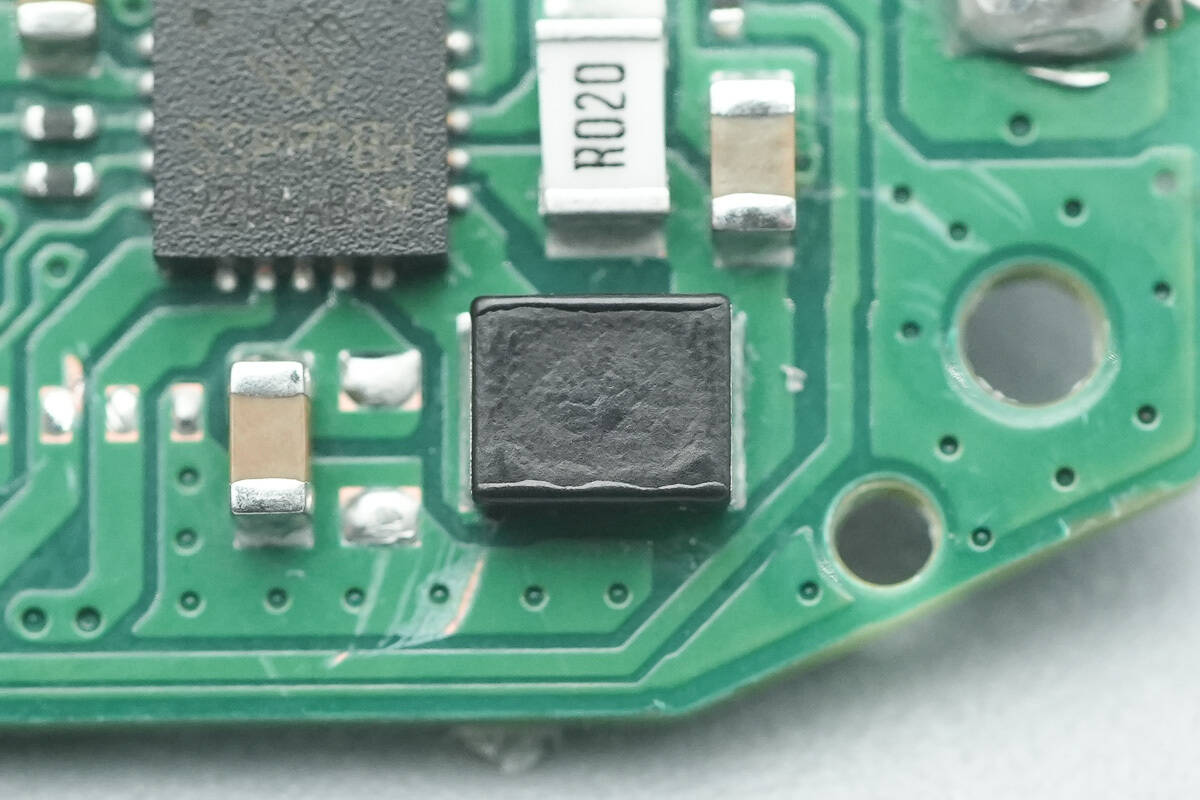
Close-up of the external SMD inductor.

The chip marked with 25T2 is used for input over-voltage protection.
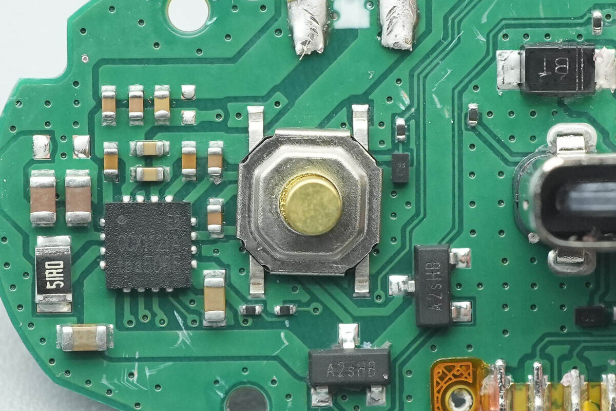
The function button is soldered using surface-mount technology.

The USB-C socket is secured using through-hole soldering.
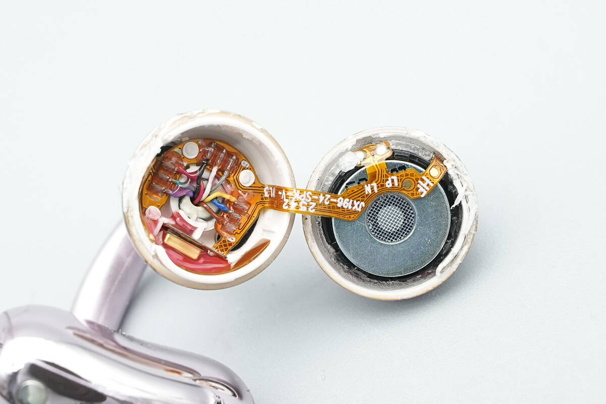
Next, disassemble the earphones by opening the outer shell along the seam. The speaker is connected via a flex cable.

The speaker is connected via a soldered flex cable.
After removing the speaker, a noise-canceling microphone is present inside.
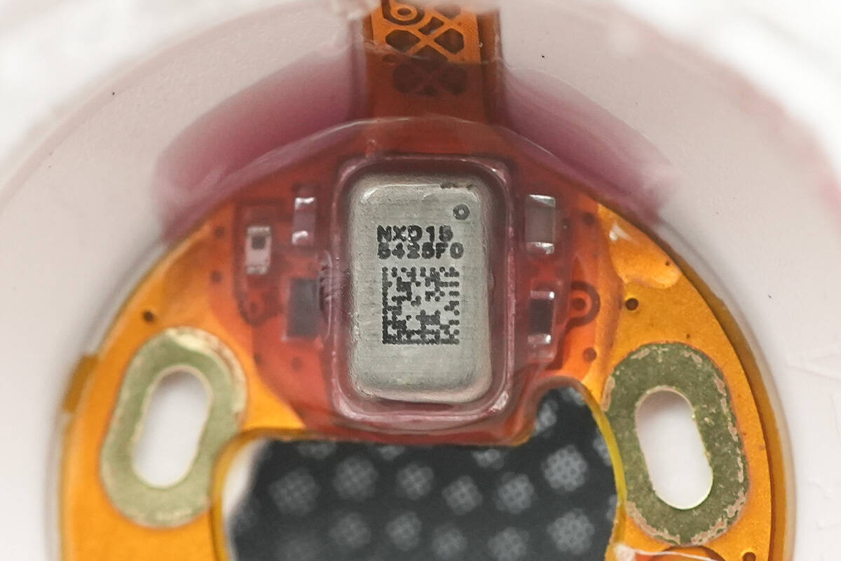
The noise-canceling microphone is sealed with adhesive.

The internal flex cable inside the enclosure is connected via soldered wires.
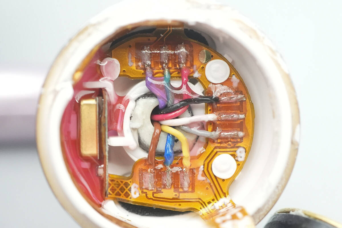
The wire solder joints are reinforced with adhesive, and a pickup microphone is located on the side.
Close-up of the pickup microphone.
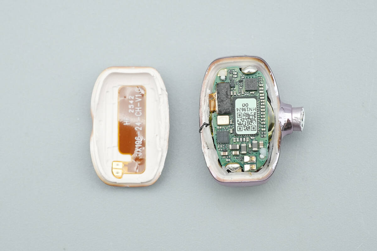
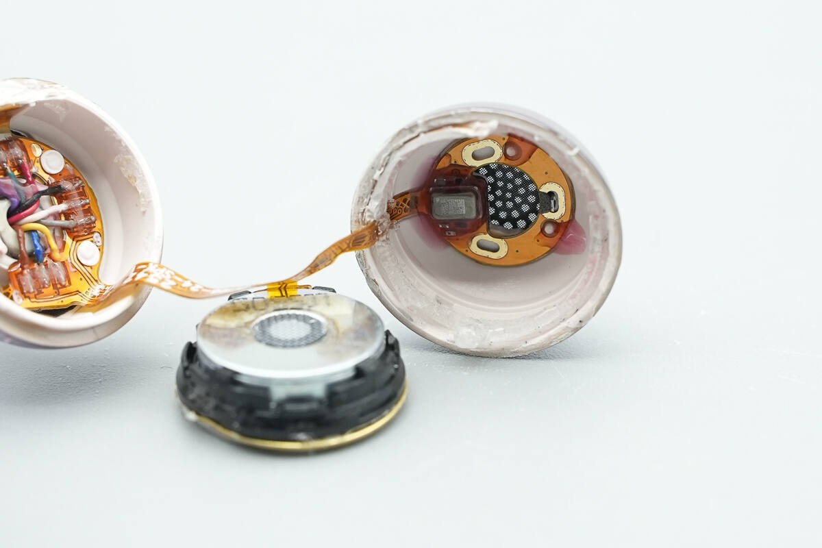
The rear enclosure is disassembled.
A touch sensor pad is present inside.

Bluetooth antennas are soldered on both sides of the PCBA module, and a flex cable connector is located at the upper right.
Close-up of the flex cable connector for the microphone and speaker.

After removing the PCBA module, a frame is provided below to secure the battery.
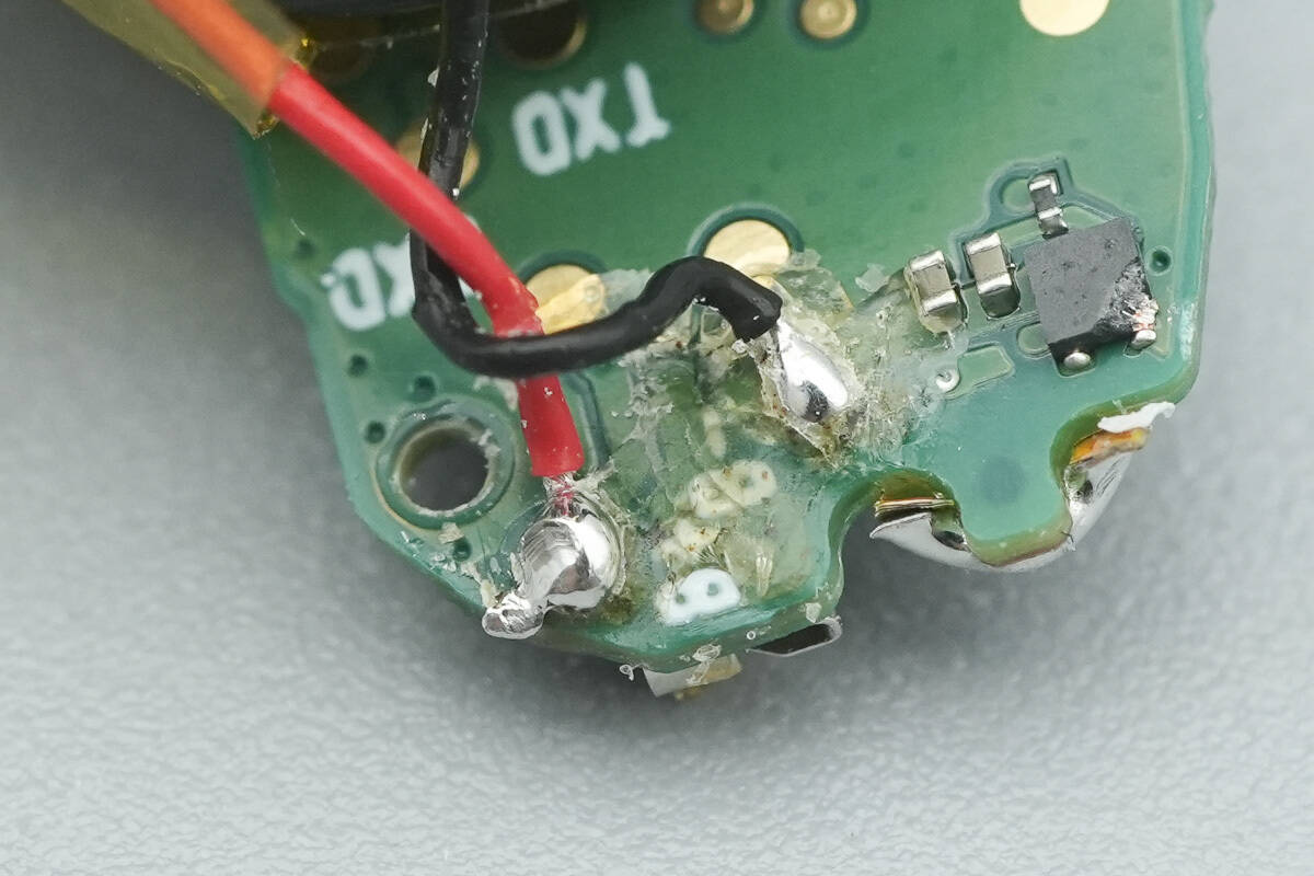
The battery is connected via soldered wires.
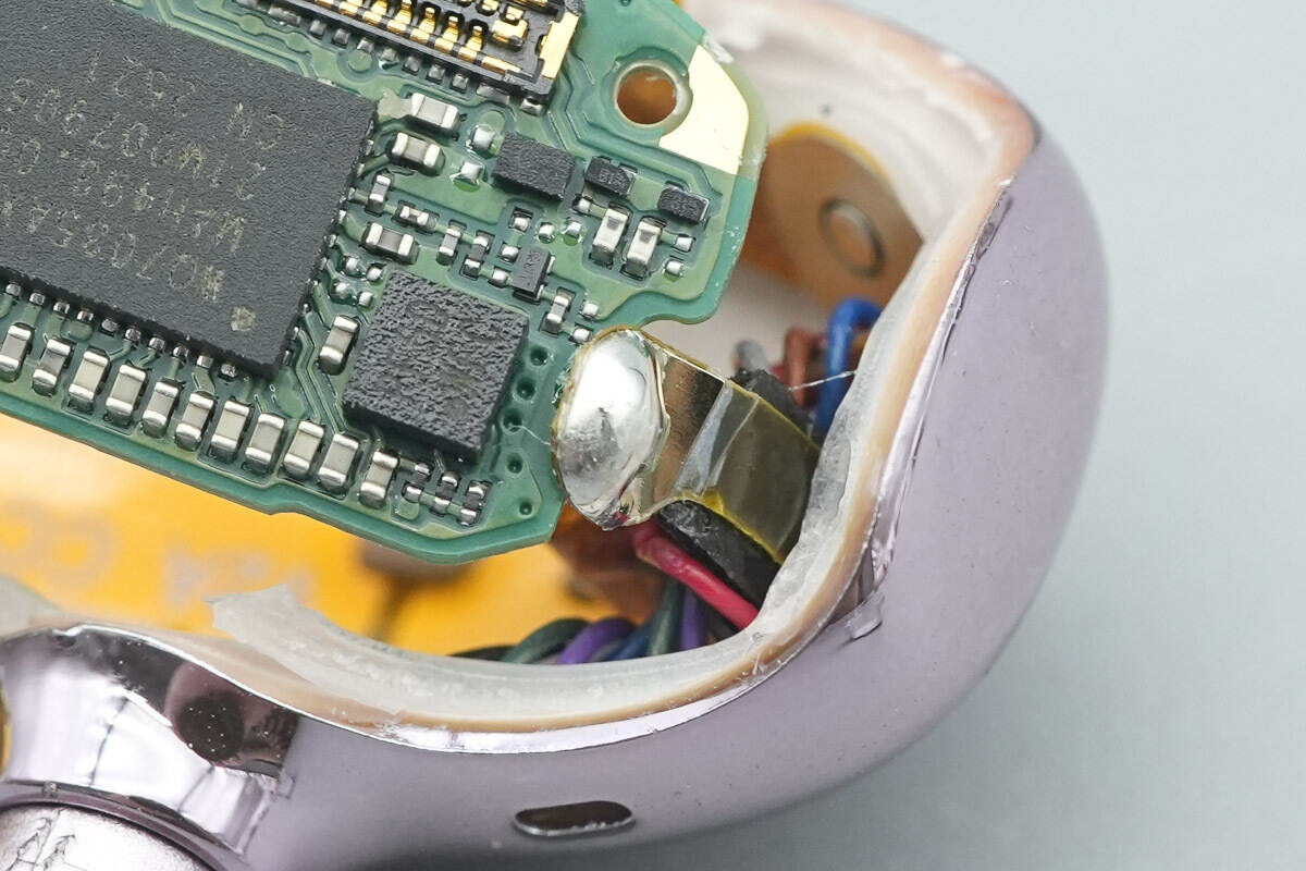
The Bluetooth antenna is soldered to the PCBA module.
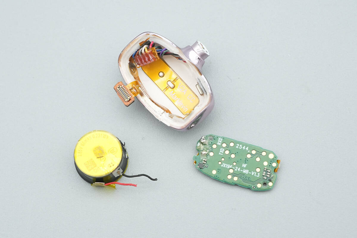
The PCBA module is disconnected from the battery and the enclosure.

The steel-cased coin cell battery is insulated with a plastic sleeve; the negative terminal is spot-welded to a tab and insulated with high-temperature adhesive tape.
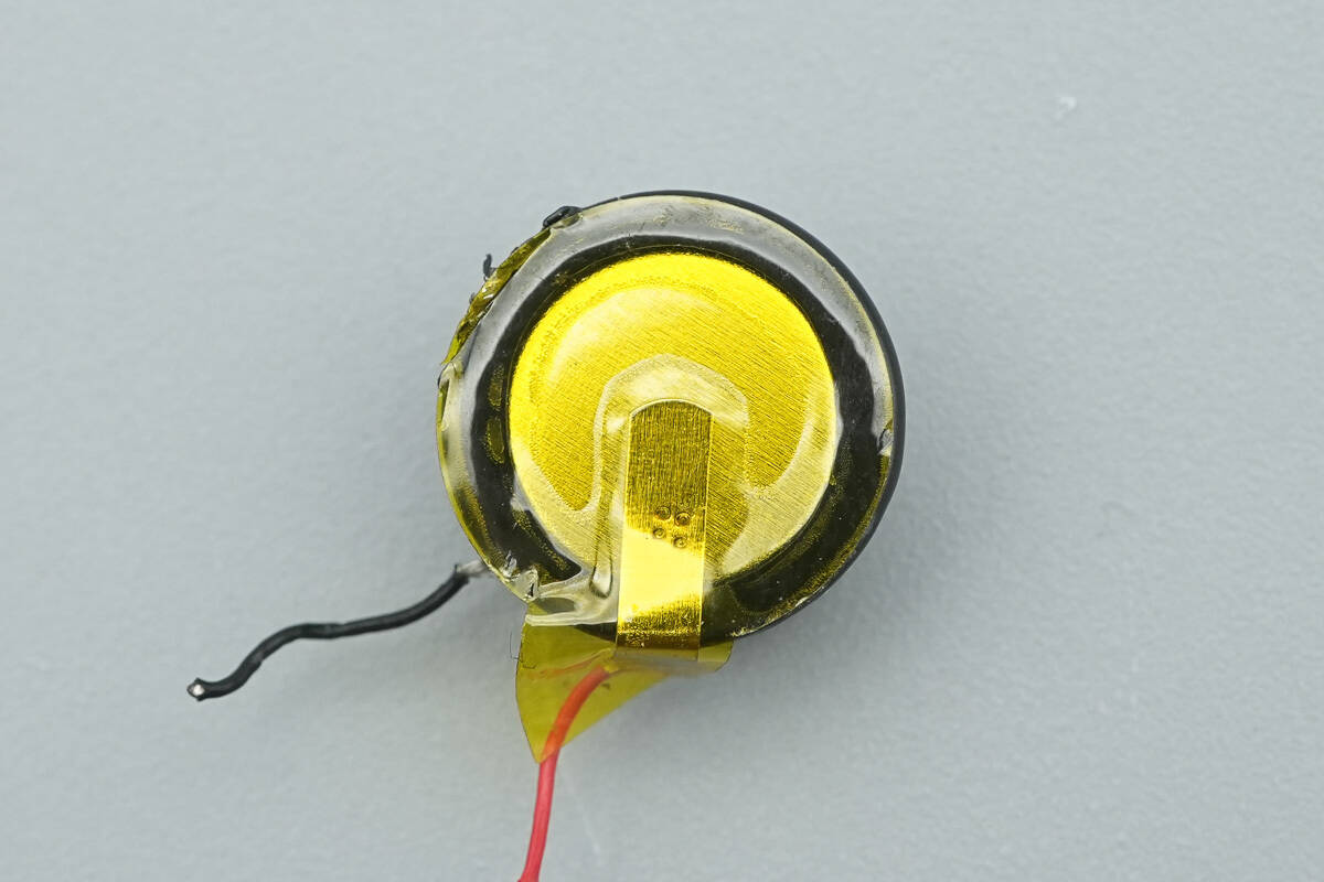
The positive terminal is connected via a spot-welded tab.
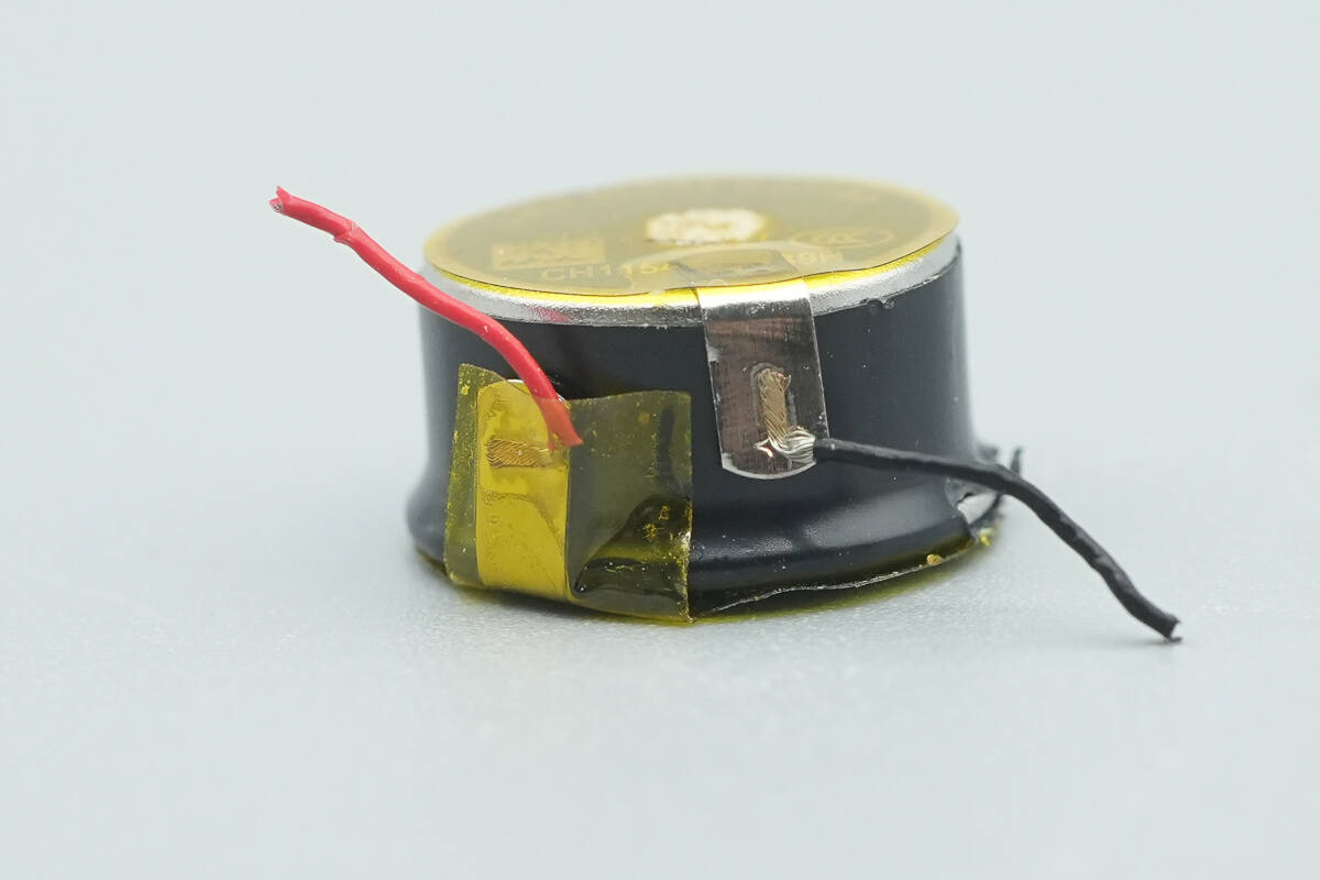
The side of the battery is insulated with a plastic sleeve.
Close-up of the SMT Bluetooth antenna at the bottom of the enclosure.

Foam padding is applied between the flex cables for isolation.

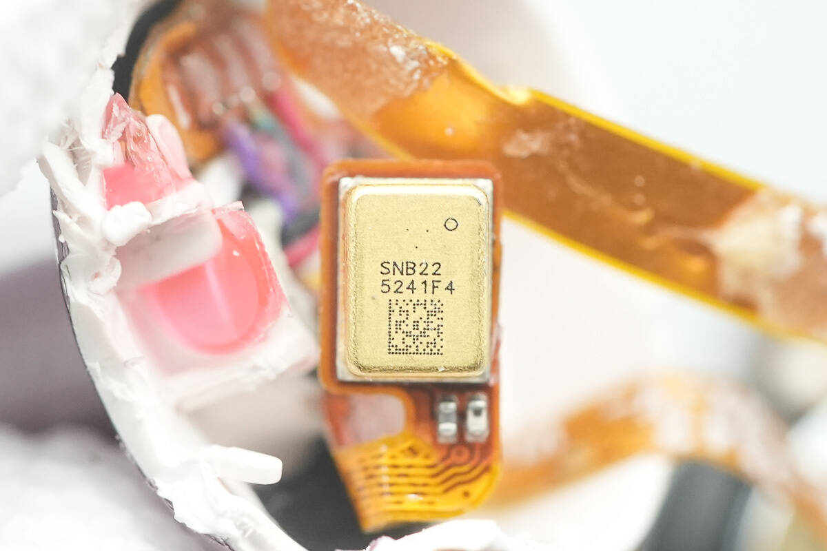
Close-up of the microphone.
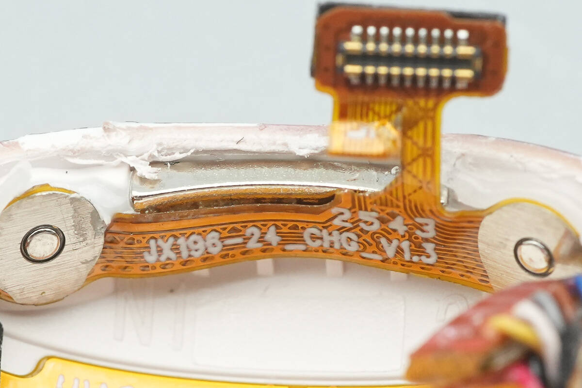
The charging contacts are connected to the flex cable, with an internal magnetic attachment provided.

Close-up of the flex cable connector.
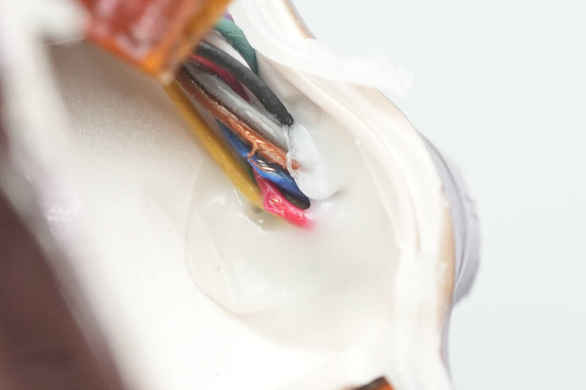
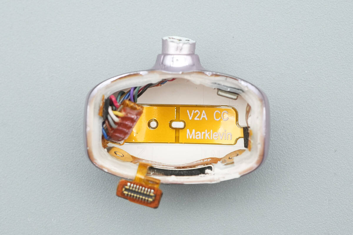
The internal wiring of the headphone's titanium bridge is connected via wires and sealed with adhesive.

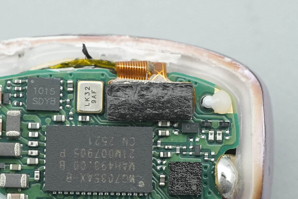
The PCBA module includes a master control IC, a gyroscope, a connector, a clock crystal oscillator, touch contacts, and related components.
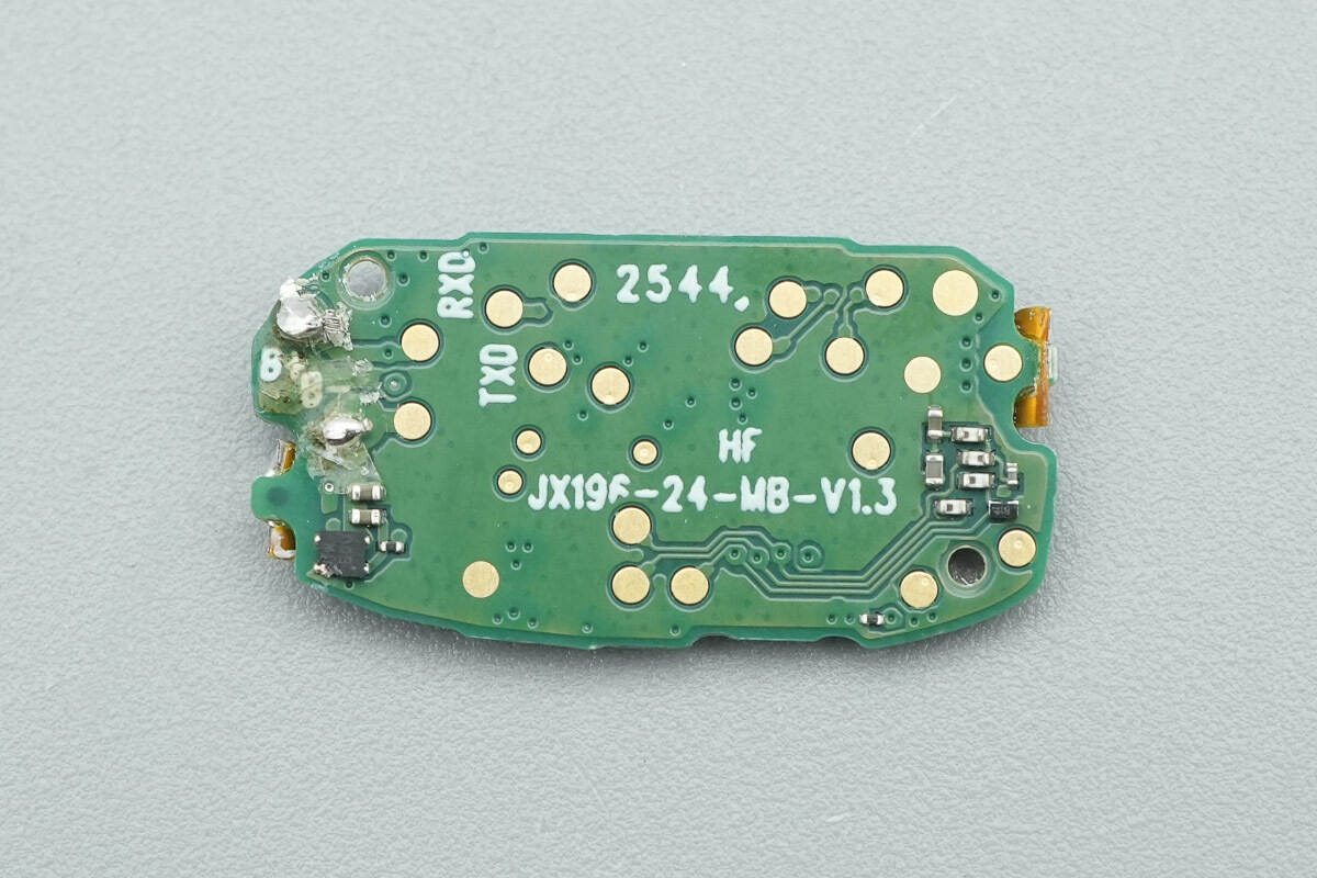
A battery protection chip is located on the rear side.
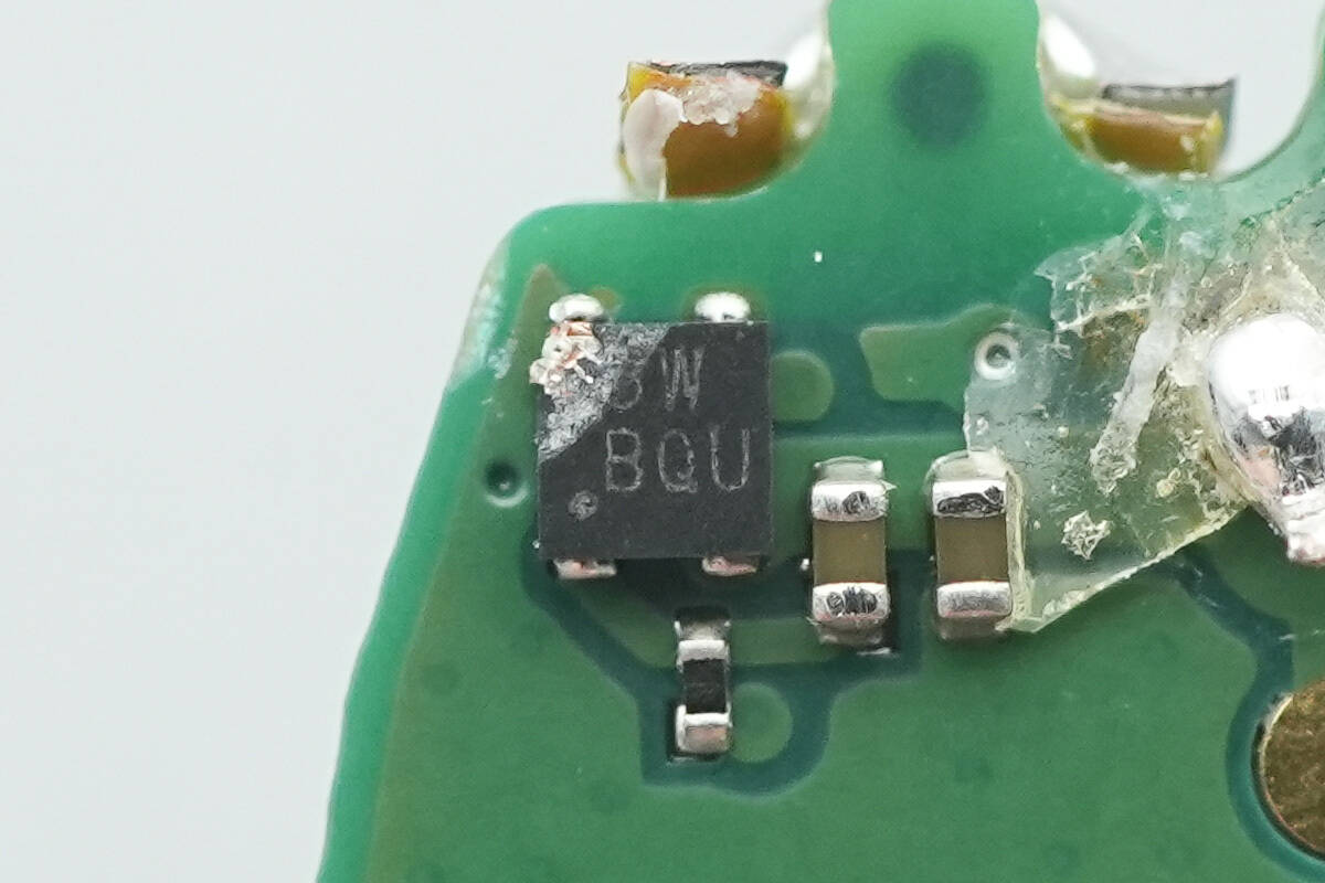
The integrated battery protection chip marked “5W BQU” is present.
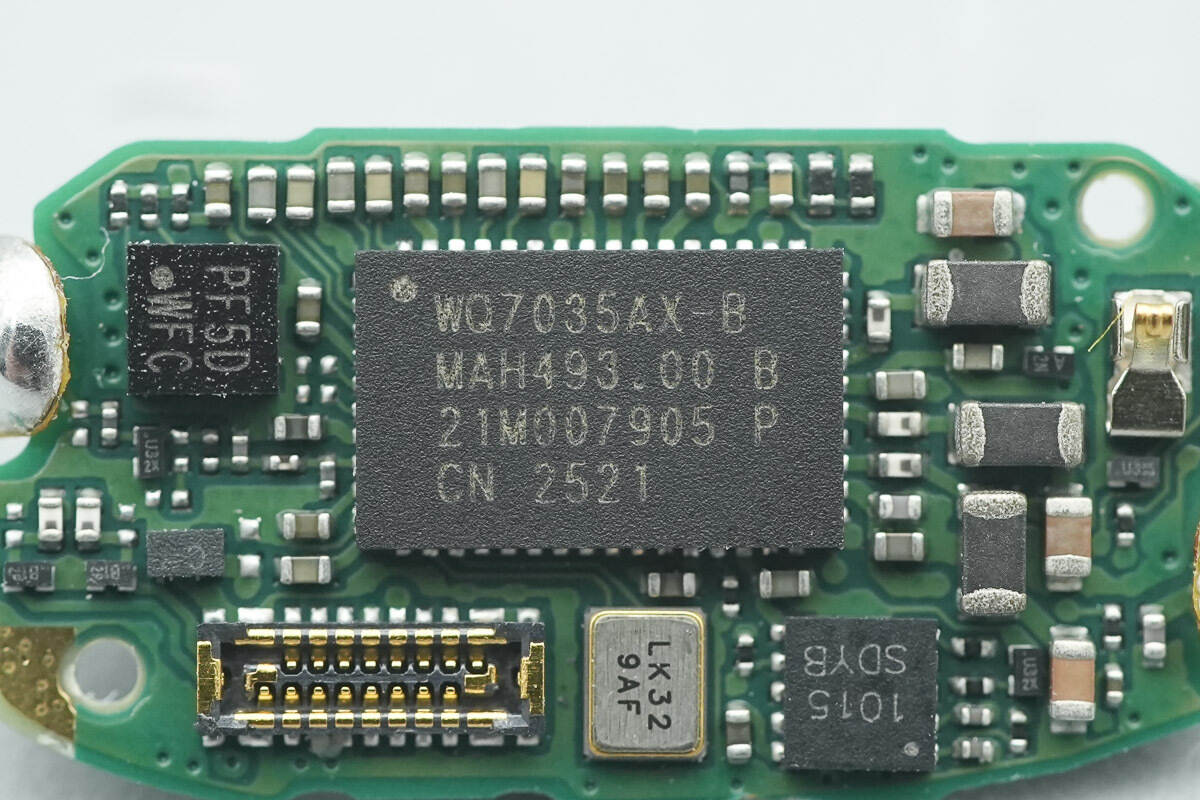
The Bluetooth audio SoC is from WUQI Micro, model WQ7035AX-B, in a QFN52 package.
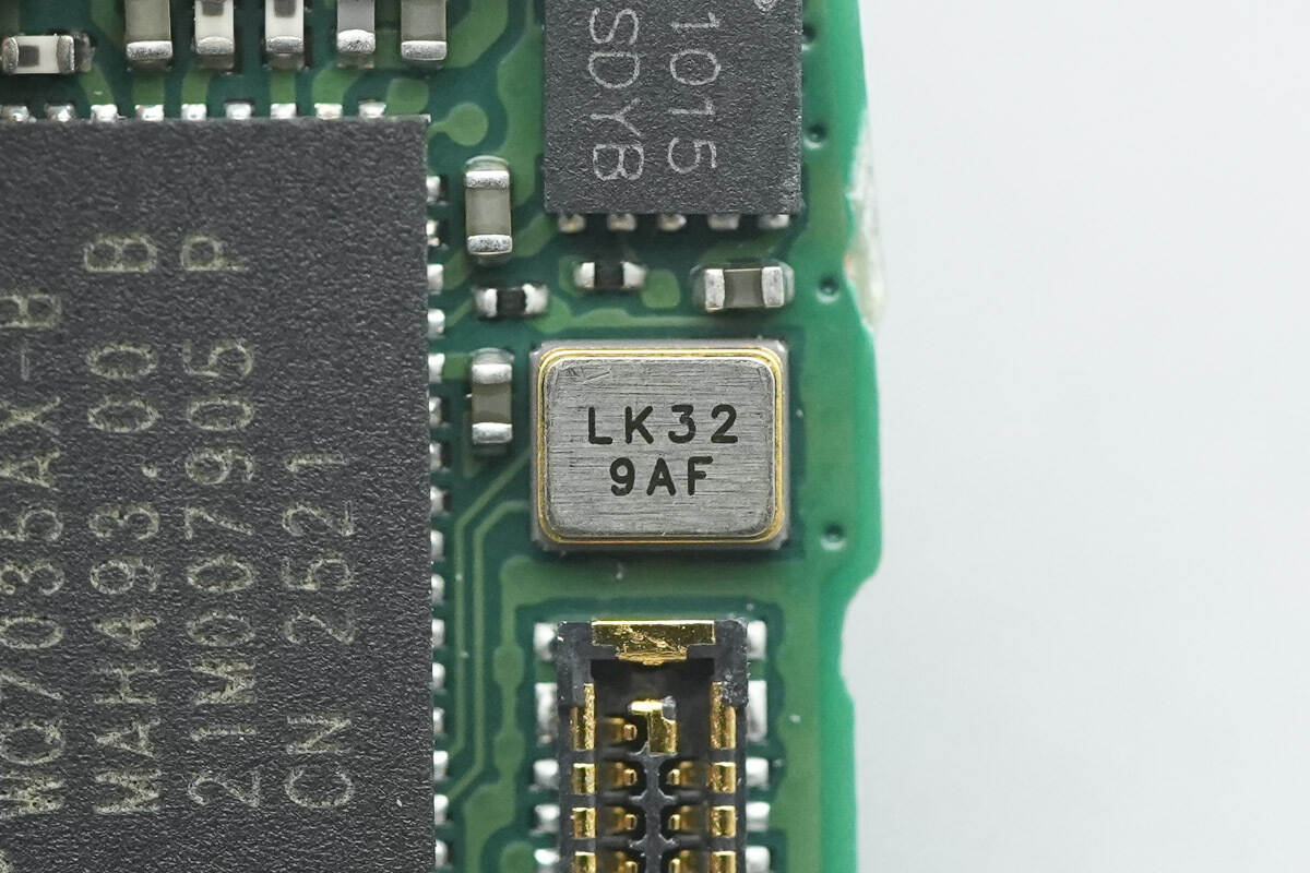
Close-up of the clock crystal oscillator.

Three inductors are located on the right side.

Close-up of the chip marked “1015SDYB.”

Close-up of the chip marked “PF5D WFC.”
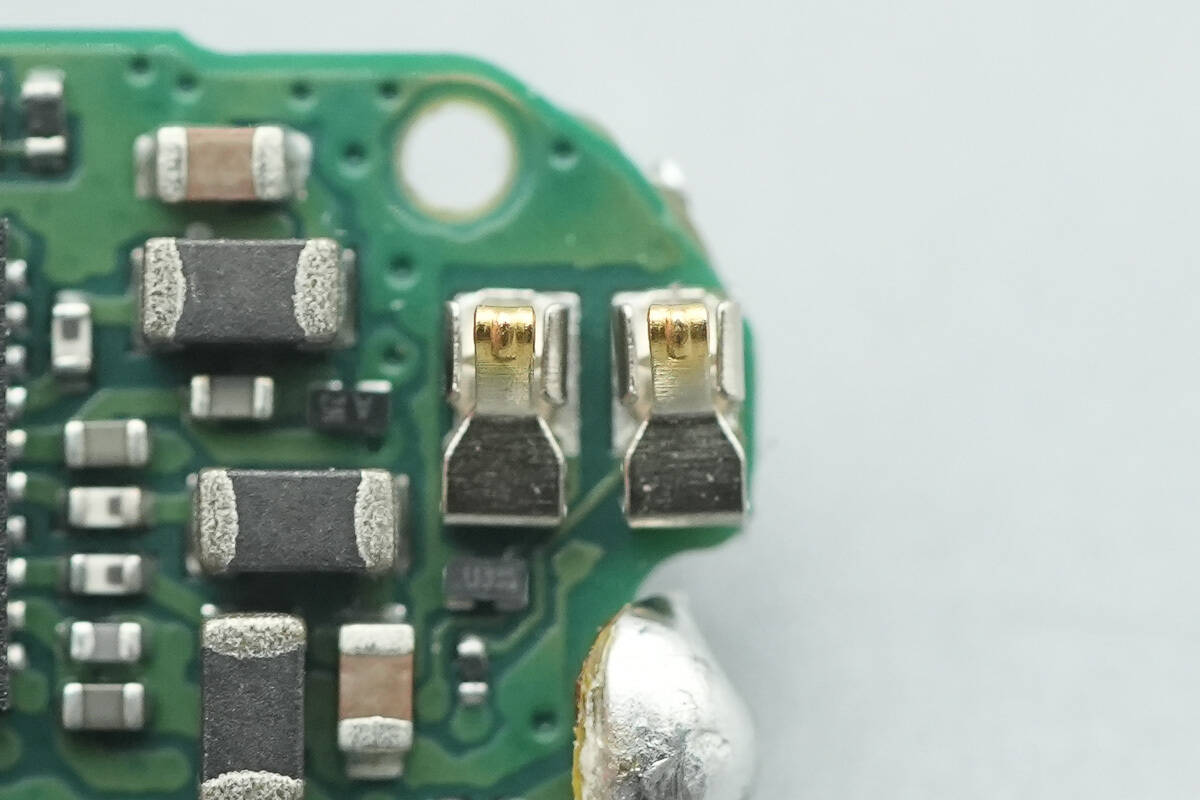
Close-up of the spring contacts connecting to the touch pad.
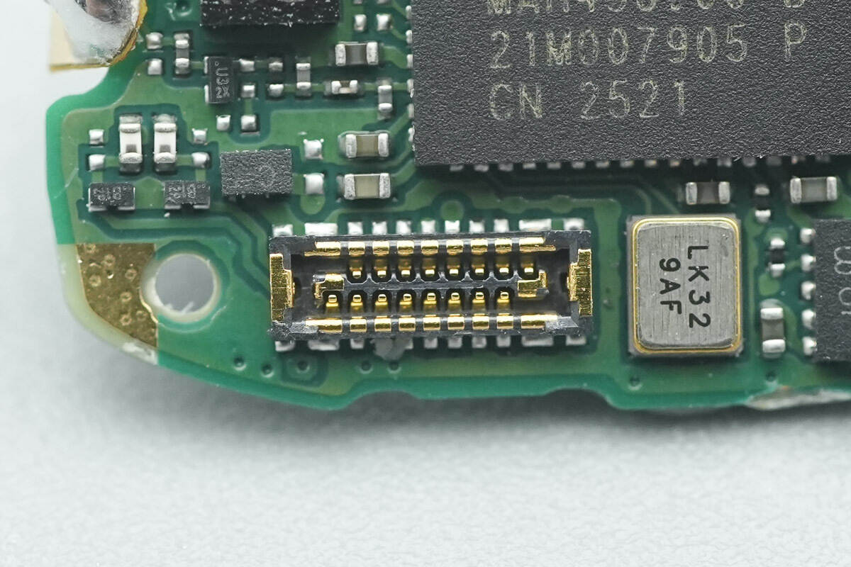
Close-up of the flex cable socket connecting the speaker and microphone.

Well, those are all components of the Honor Choice LCHSE Clip-On Earphone 2 Pro.
Summary of ChargerLAB
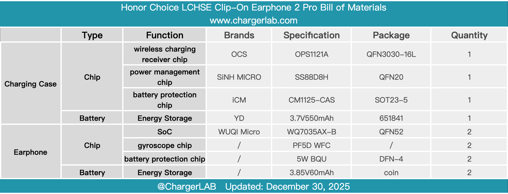
Here is the component list of the Honor Choice LCHSE Clip-On Earphone 2 Pro for your convenience.
It features a built-in 12 mm dual-magnetic driver with an LCP diaphragm. A single charge provides up to 10 hours of playback and up to 44 hours of extended battery life when used with the charging case. The charging case also supports wireless charging.
After taking it apart, we found that it uses the OCS OPS1121A wireless charging receiver chip. This chip is a highly integrated single-chip wireless charging solution featuring a minimal external component count and high conversion efficiency, and it supports seamless switching between wired and wireless charging while integrating comprehensive protection functions.
It uses the SiNH MICRO SS88D8H power management chip paired with the iCM CM1125-CAS battery protection chip. The WUQI Micro WQ7035AX-B Bluetooth SoC is employed, together with three microphones. Internally, the earphones are interconnected via flex cables and soldered wires, and the battery is secured by a frame, reflecting reliable build quality.
Related Articles:
1. Teardown of Moore Threads MTT S70 Graphics Card
2. Teardown of Pisen 160W 4-USB-C GaN Charger (TP-C81)
3. Teardown of Highsay C1 Pro 140W Ultra Charger