Introduction
GreatWall has launched the SPARK GaN 850W fully modular power supply. It features a fully modular design, comes with a 7-year warranty, and is certified 80 PLUS Gold for energy efficiency. The unit complies with the Intel ATX 3.1 power supply specification and is equipped with a native PCIe 5.1 connector. It provides a single 12V rail with a high current output of up to 70.8A, meeting the power demands of high-performance PC configurations.
The power supply adopts a mainstream high-efficiency topology consisting of active PFC, half-bridge LLC resonance, synchronous rectification, and DC-to-DC conversion. It integrates Innoscience GaN power ICs, enabling a significant generational leap in both performance and energy efficiency. Next, let’s take a closer look at its internal components and design.
Product Appearance
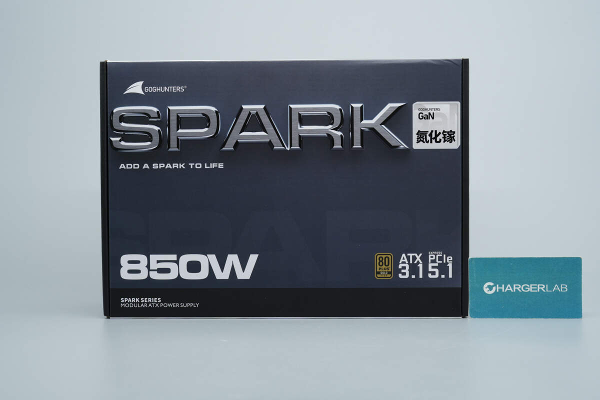
The top of the packaging is printed with “SPARK” and “GaN,” while the bottom displays “850W,” the 80 PLUS Gold certification logo, and the ATX 3.1 and PCIe 5.1 markings.

The top of the packaging box is printed with the “SPARK 850W” branding.
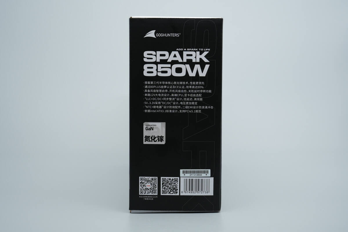
The side of the packaging highlights the product’s key selling points.
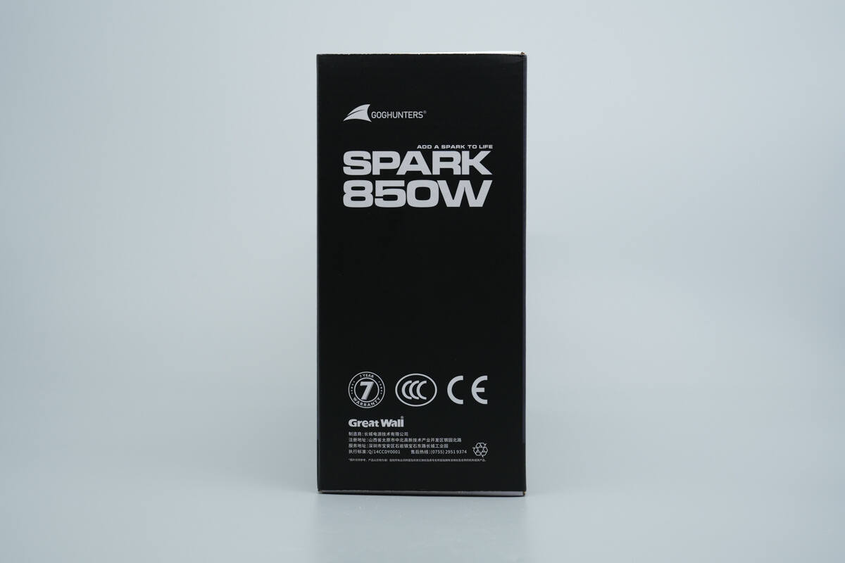
The opposite side is printed with the 7-year warranty badge and the CCC and CE certification logos.
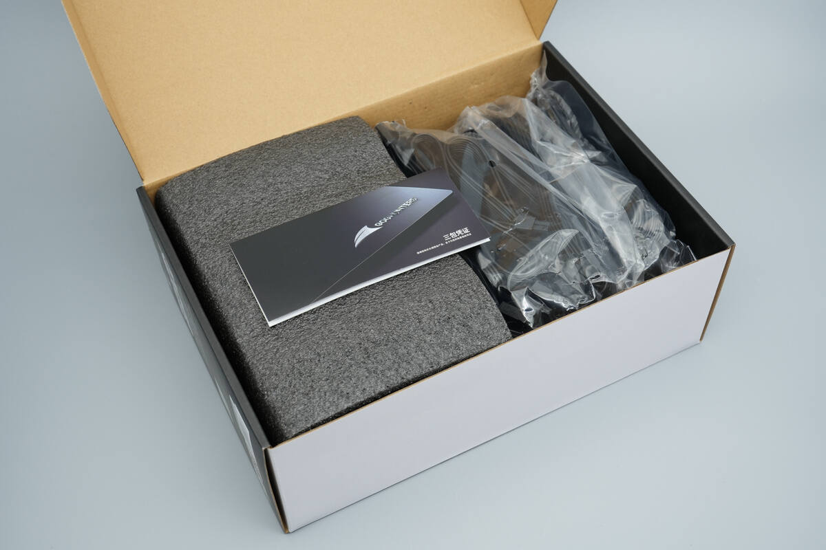
Inside the packaging, a user manual is included. The power supply is wrapped in protective foam, while the modular cables are packaged in plastic bags.

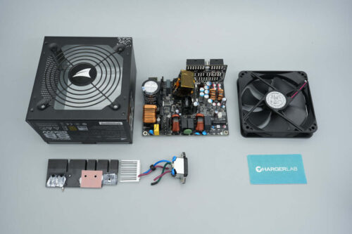
An overview of the power supply, AC power cord, modular cables, and warranty documentation.
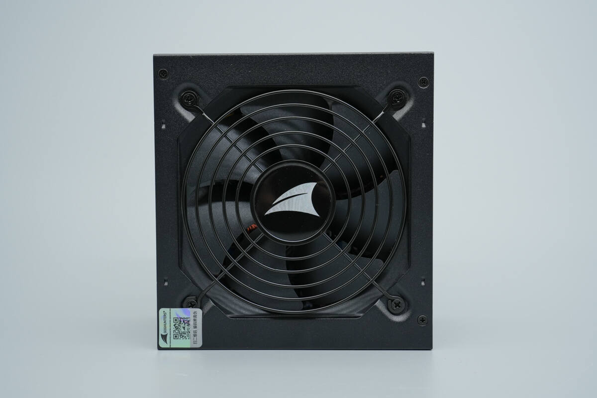
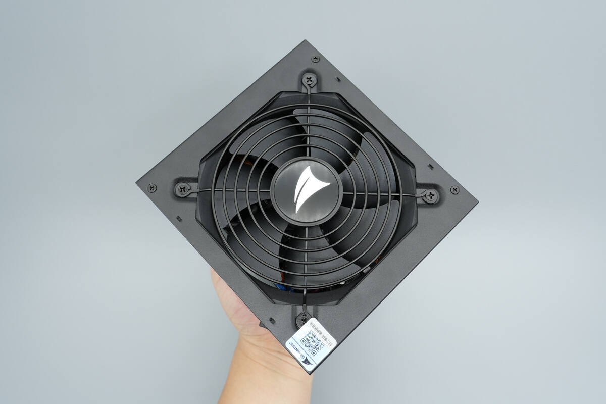
The cooling fan on the top is equipped with a protective grille.
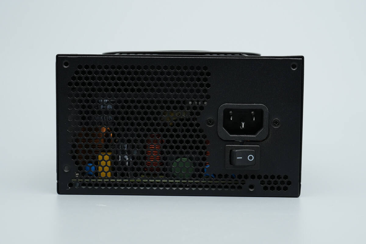
The input side features the power input socket and a power switch.
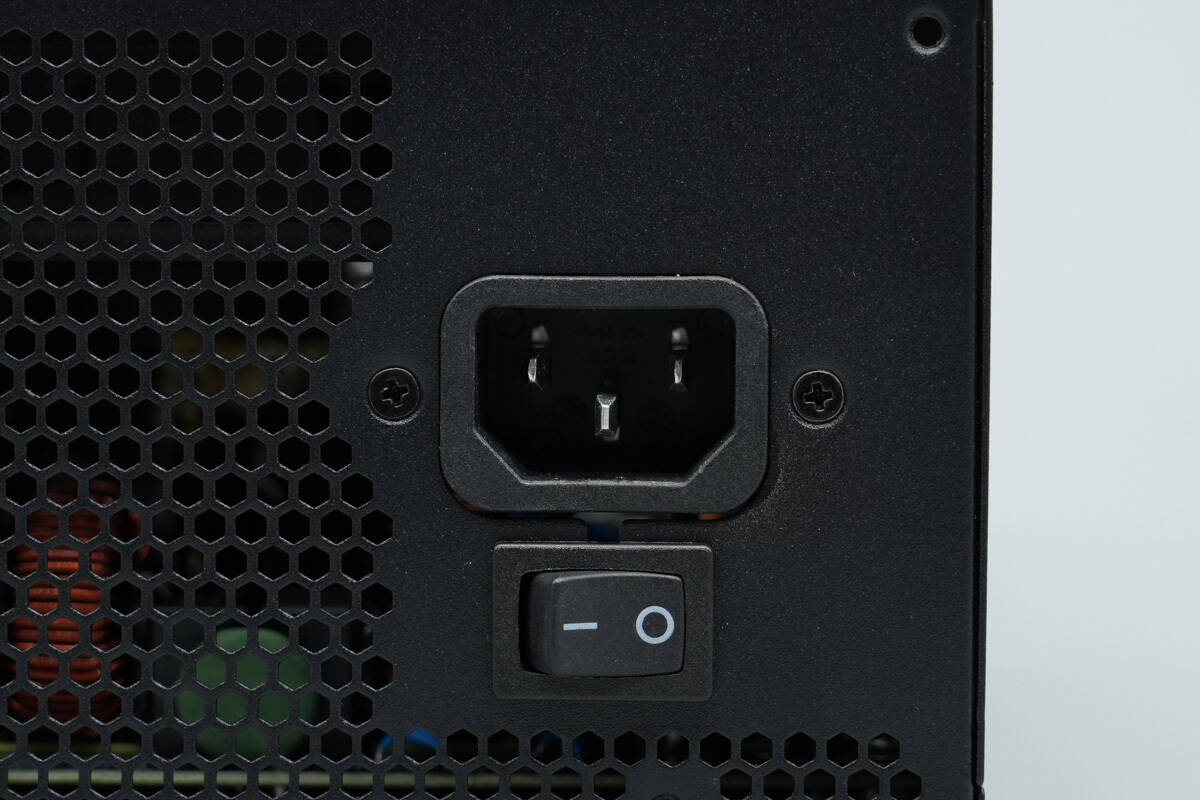
The input socket is secured with screws.

On the opposite side of the unit, there are CPU and PCIe connectors, below which are peripheral and SATA connectors, and at the bottom is the motherboard power connector.
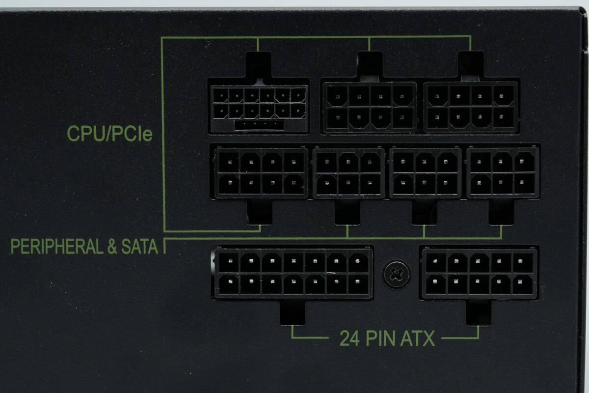
Close-up view of the connector area.
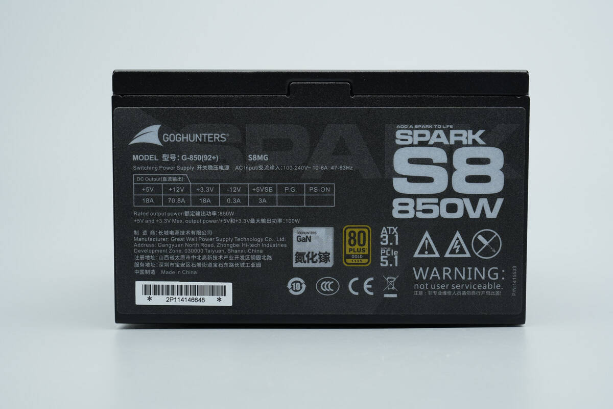
An information label is affixed on this side.

Model: G-850 (92+)
AC Input: 100–240V~ 10–6A 47–63Hz
DC Output: +12V ⎓ 70.8A
+5V ⎓ 18A
+3.3V ⎓ 18A
-12V ⎓ 0.3A
+5VSB ⎓ 3A
Rated Output Power: 850W
Maximum Output Power for +5V and +3.3V: 100W
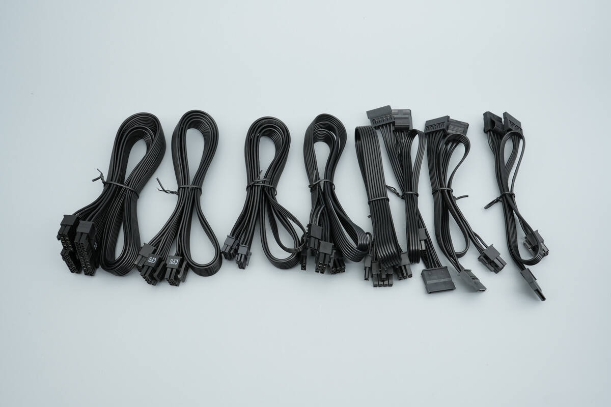
Overview of the included modular cables.
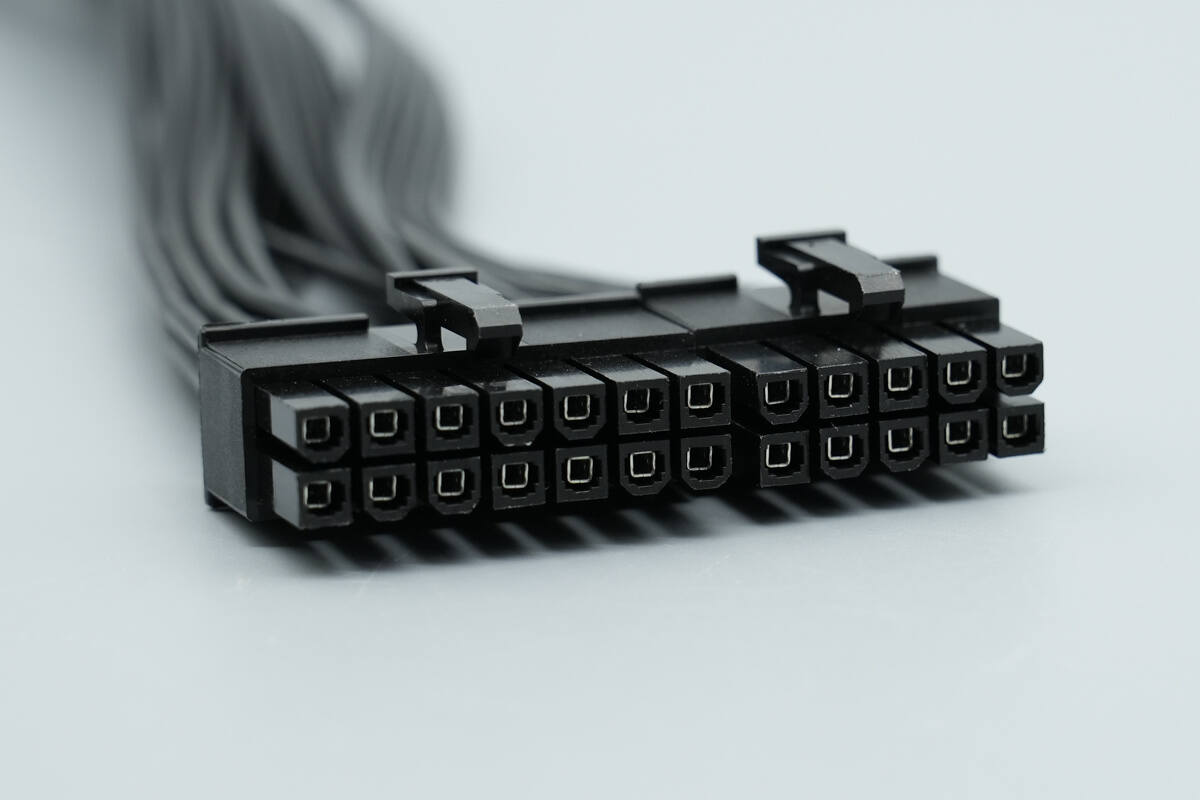
Overview of the 24-pin connector on the power supply.

Overview of the 24-pin connector on the motherboard end.
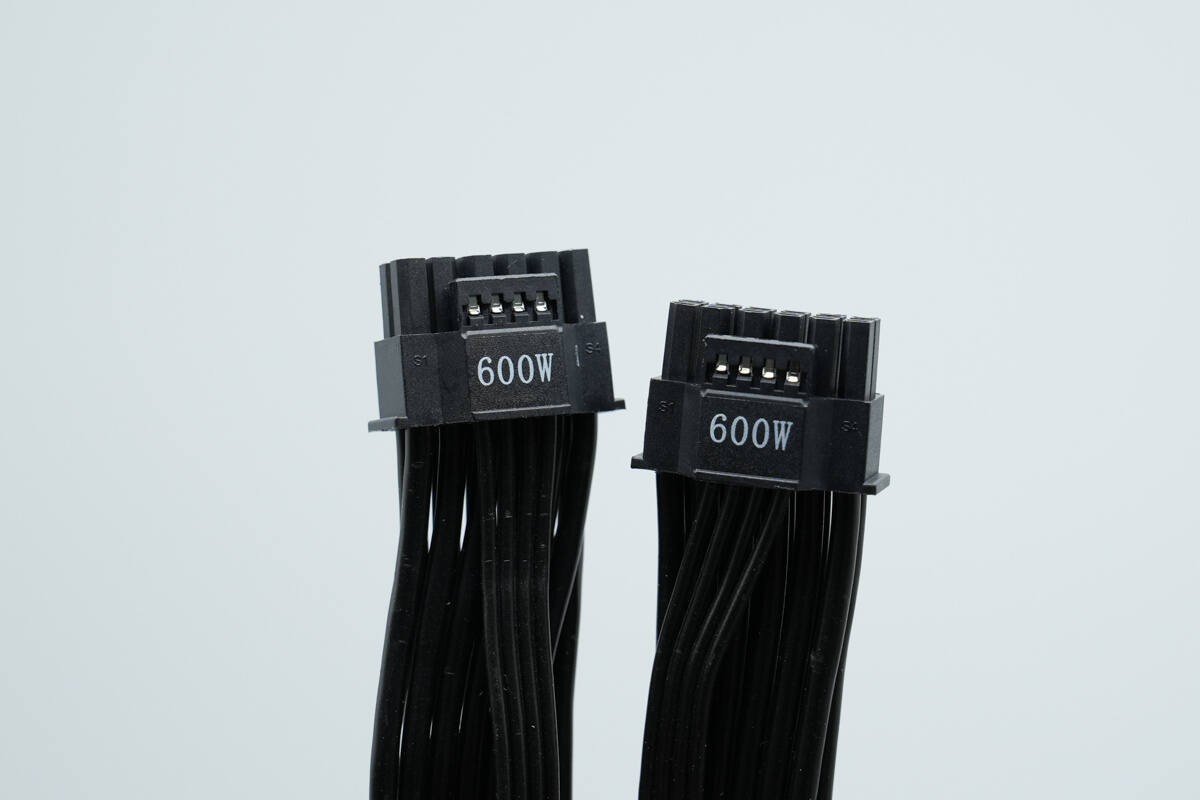
The PCIe 5.1 12V 2×6-pin power cable supports up to 600W.
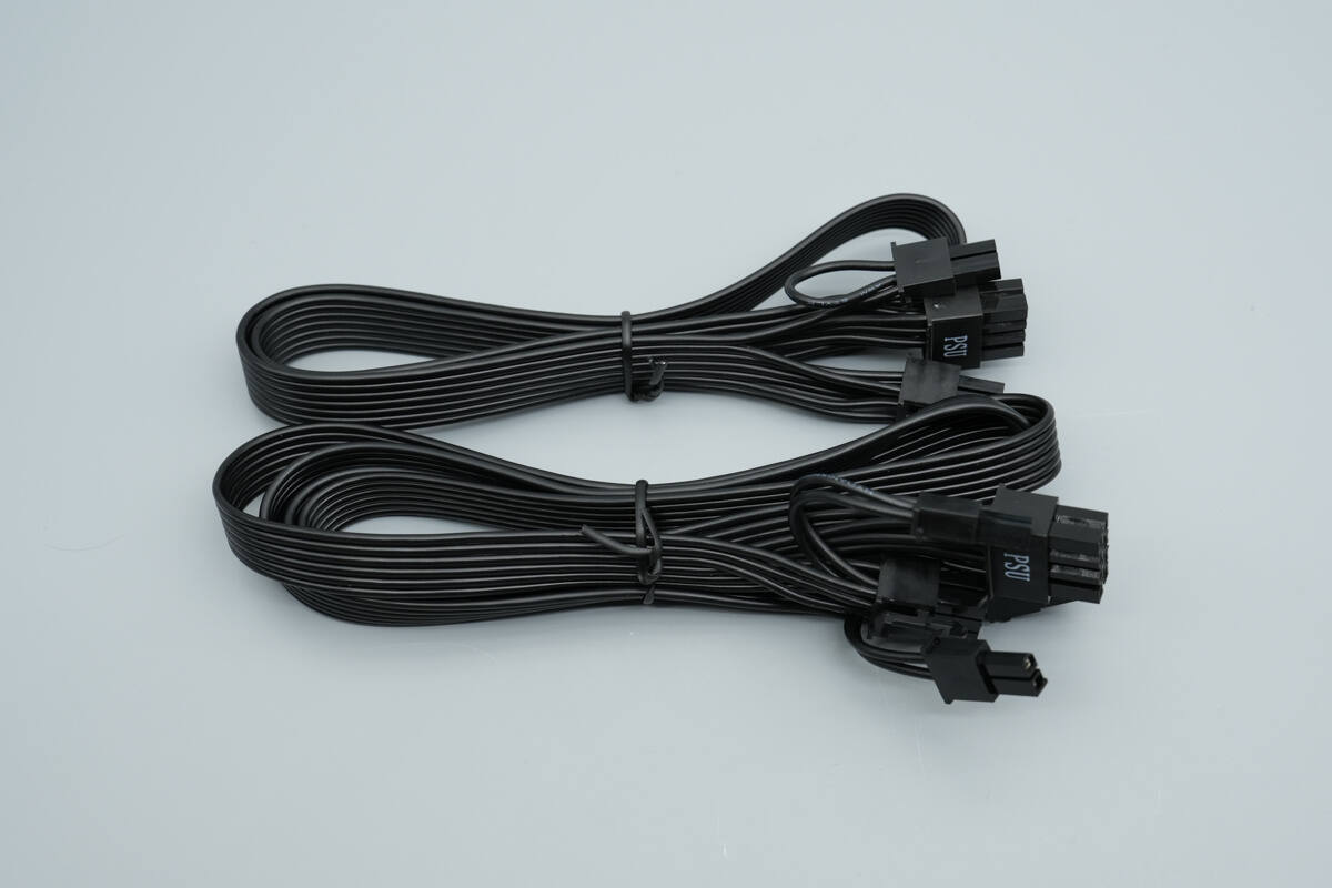
Close-up of the PCIe graphics card power cables.
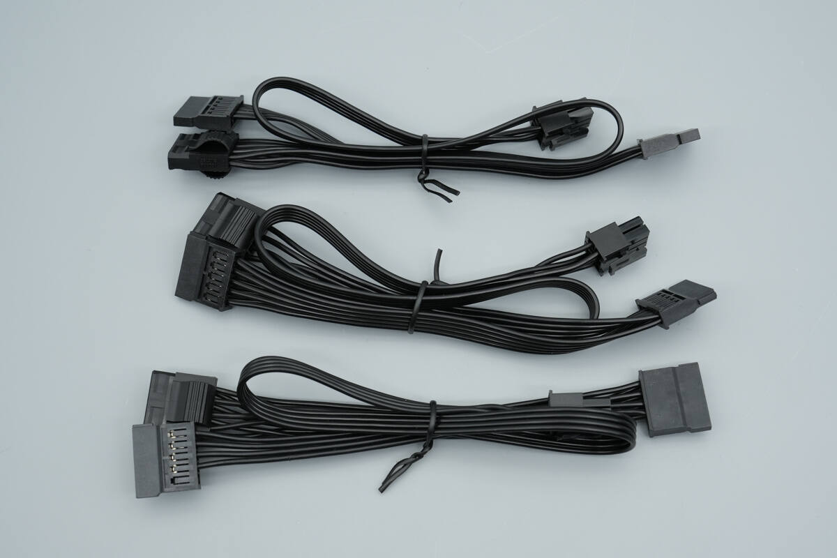
Close-up of the power supply’s SATA and 4-pin connector cables.
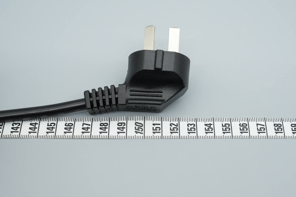
The length of the included power cable is about 153 cm (60.24 inches).
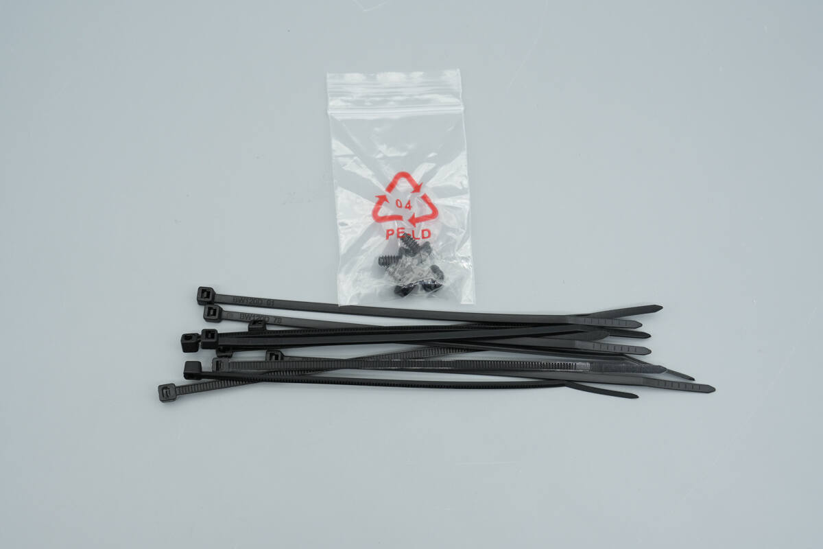
Close-up of the included mounting screws and cable ties.
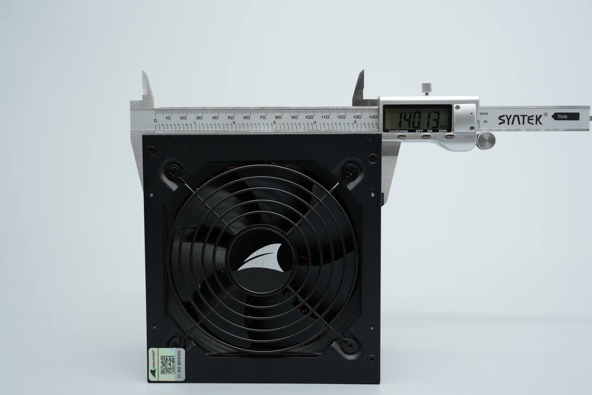
The length of the power supply is about 140.1 mm (5.52 inches).

The width is about 151 mm (5.94 inches).
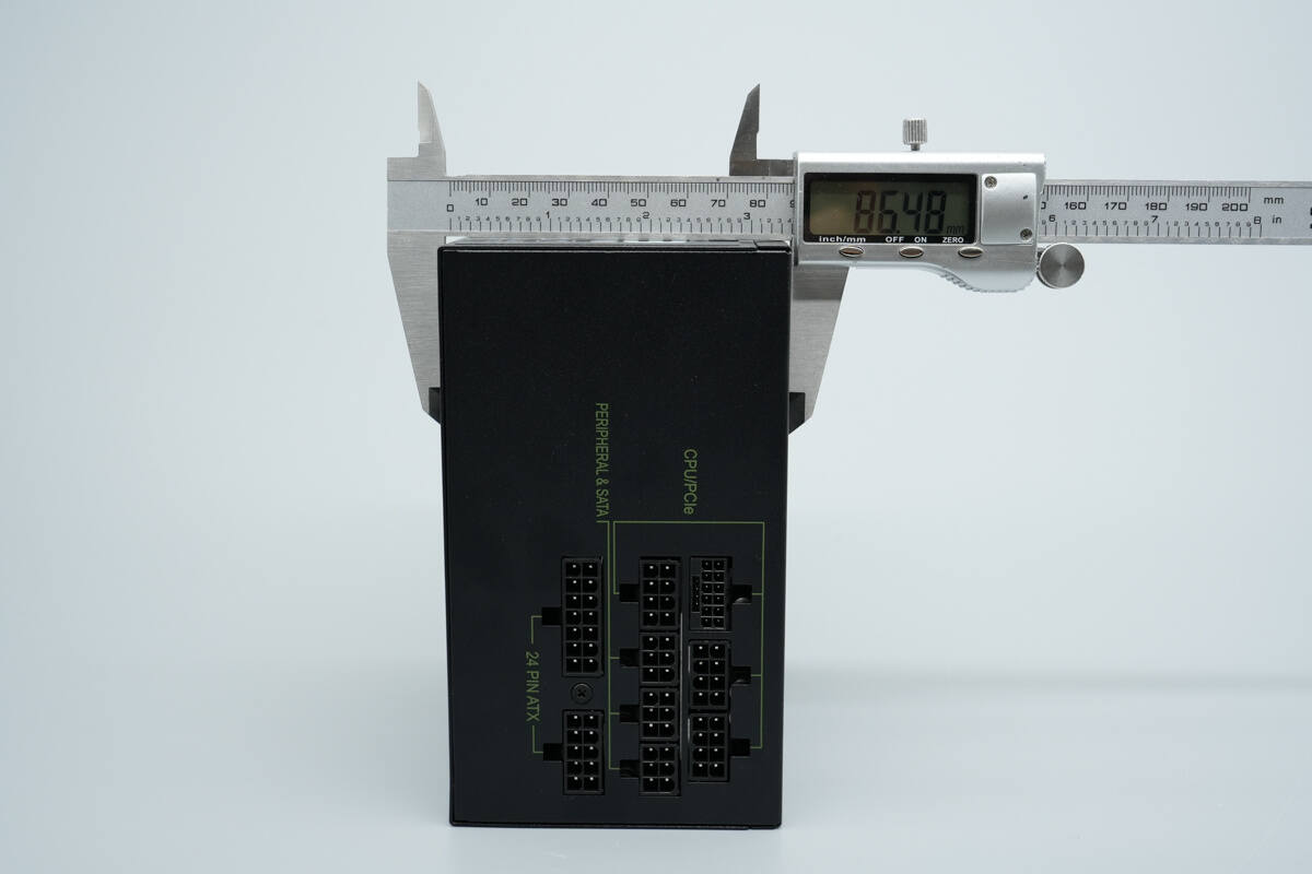
The thickness is about 86.5 mm (3.41 inches).
That's how big it is in the hand.
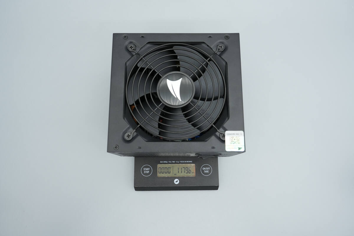
The weight is about 1180 g (41.62 oz).
Teardown
Next, let's take it apart to see its internal components and structure.
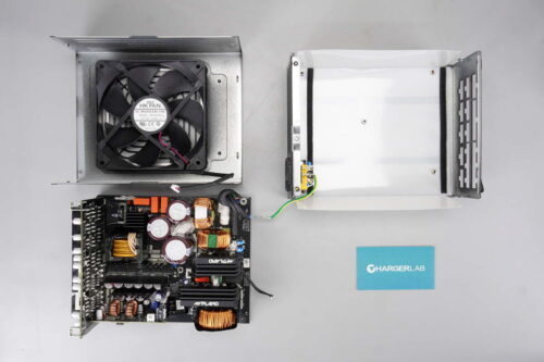
Unscrew the screws and remove the outer casing.
The cooling fan is connected via a plug-in connector.
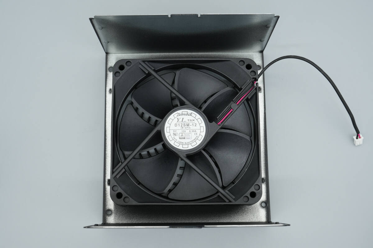
The cooling fan is from YL, model D12SM-12, rated at 12V 0.3A.
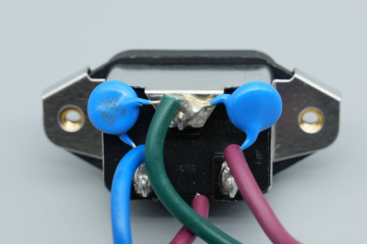
The power input socket is soldered in place, with blue Y capacitors also soldered.
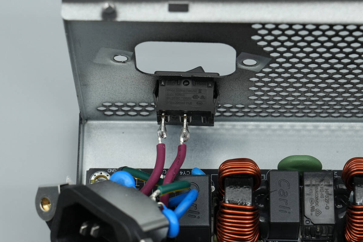
The power switch is also soldered in place.
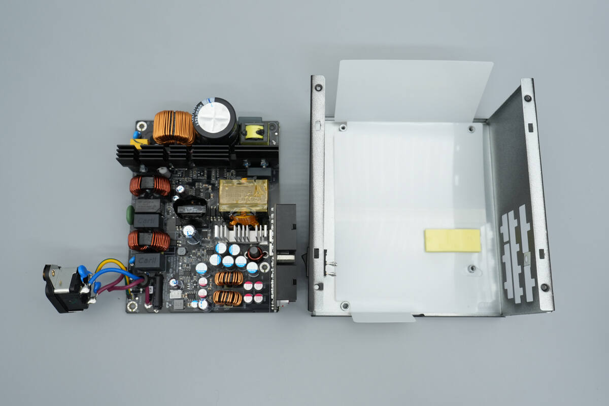
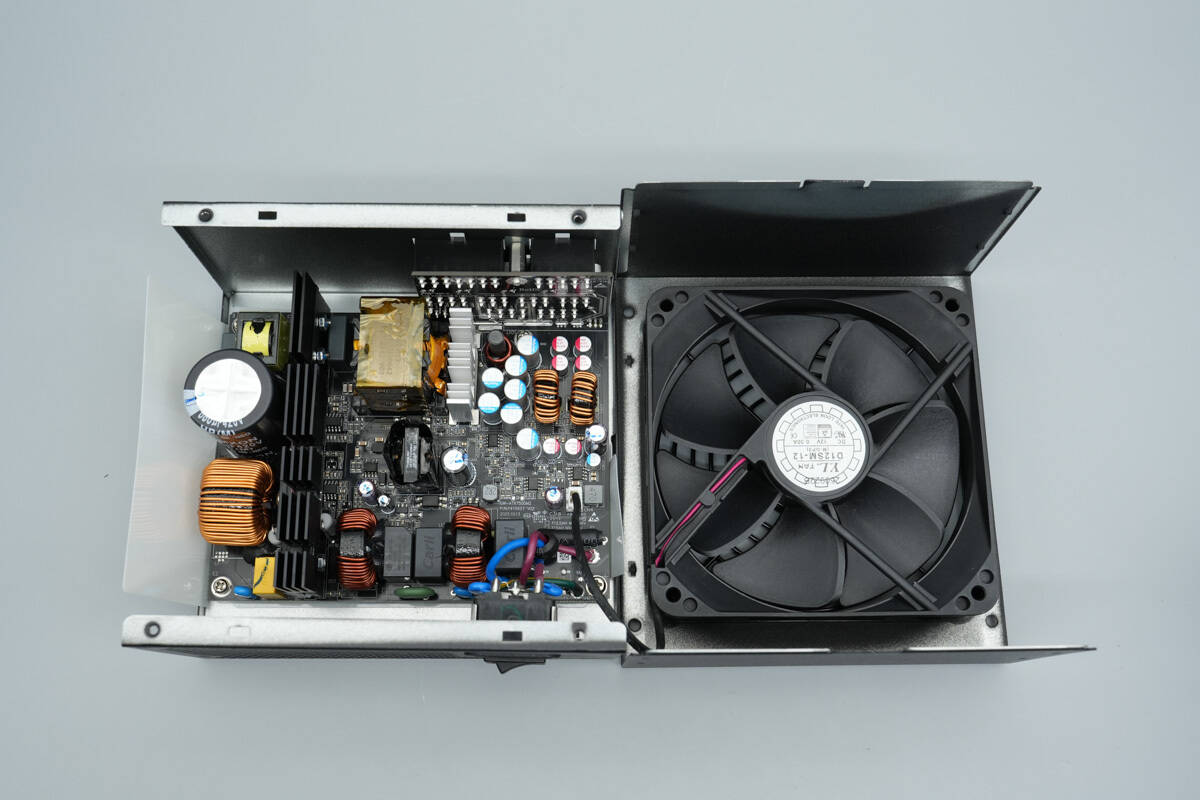
Remove the PCBA module. The interior of the casing is lined with Mylar insulation sheets.
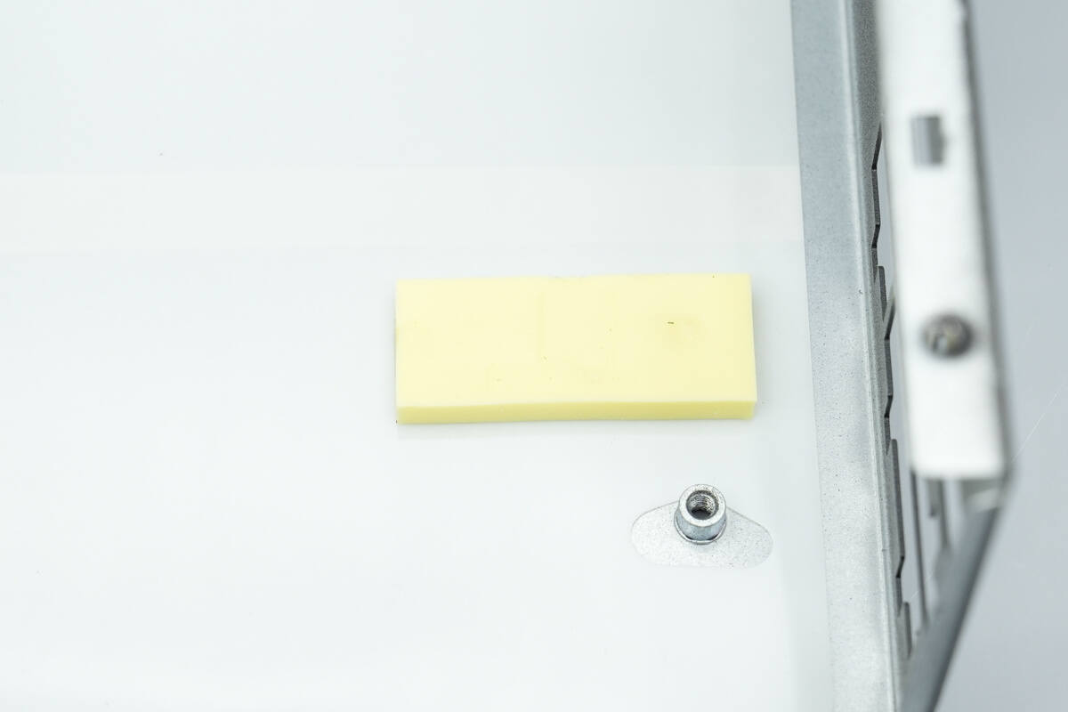
The area corresponding to the synchronous rectifier is equipped with yellow thermal pads.
The cold-pressed terminals of the input wires are soldered in place.
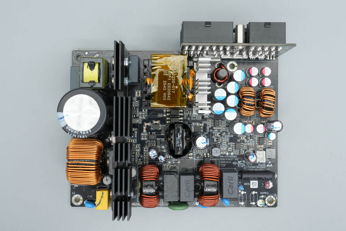
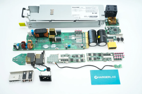
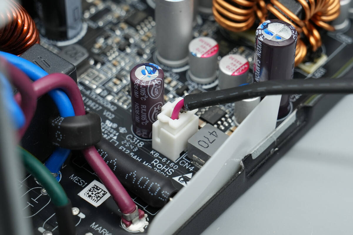
On the front side of the PCBA module, the bottom-right corner is the power input section, featuring a fuse, safety X2 capacitors, common mode chokes, a relay, and an NTC thermistor. The long, strip-shaped heatsink on the left is used for cooling the bridge rectifiers, PFC MOSFETs, the PFC rectifier, and the LLC MOSFETs. In addition, the board is populated with film filter capacitors, a PFC boost inductor, high-voltage bulk capacitors, resonant capacitors, a resonant inductor, and the LLC transformer. On the secondary side, components include synchronous rectifiers, DC-DC buck controllers, buck inductors, as well as the standby power controller and its corresponding transformer, among other devices.
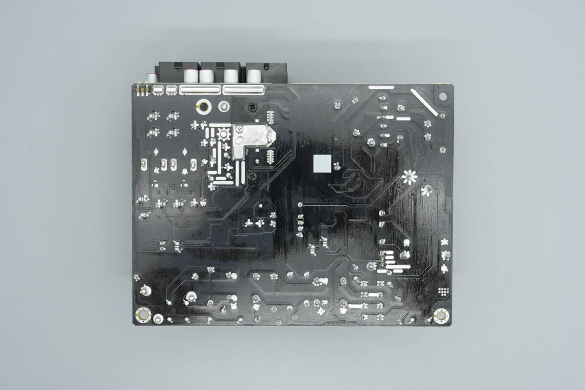
There are no components on the back.

The fuse at the input side is covered with heat-shrink tubing for insulation and is rated at 12.5A 250V.
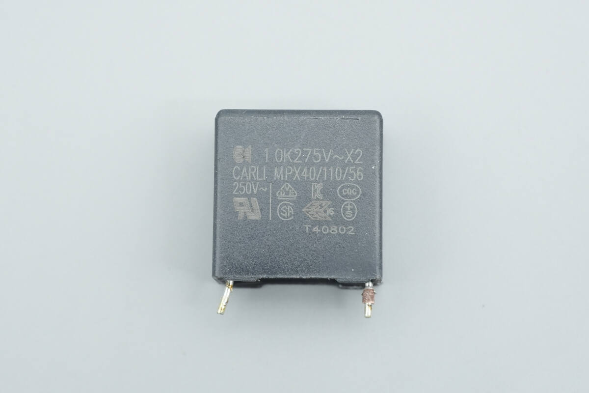
The safety X2 capacitor is from Carli and is rated at 1 µF.
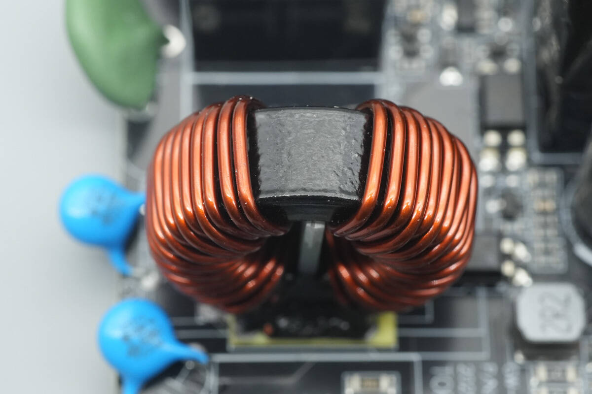
The common mode choke is wound with enameled wire, and an insulating phenolic board is installed at the bottom.
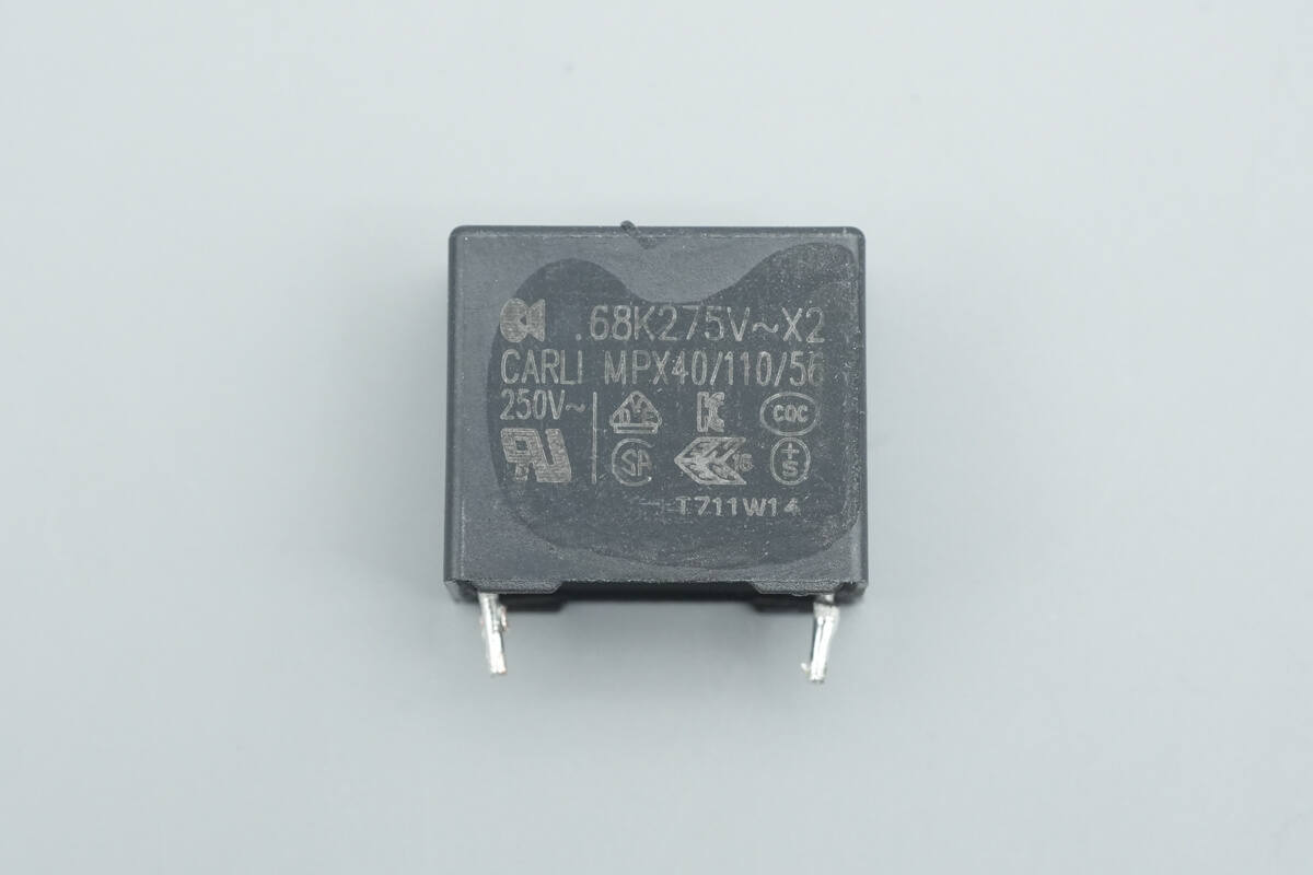
The other safety X2 capacitor is rated at 0.68 µF.
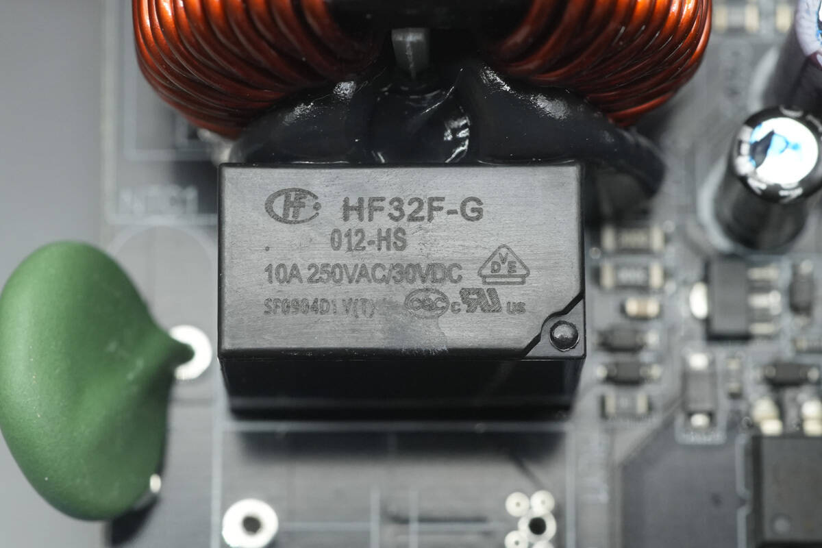
The relay is from HONGFA, model HF32F-G/012-HS. It is an ultra-compact, medium-power relay featuring a single normally open contact, with a contact switching capacity of 10A and a coil voltage of 12V.

The NTC thermistor is marked with “SCK056.”
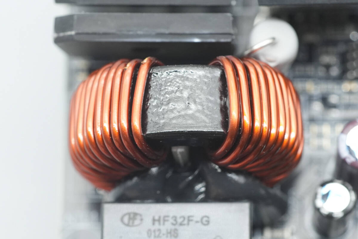
The common mode choke is wound with enameled wire.
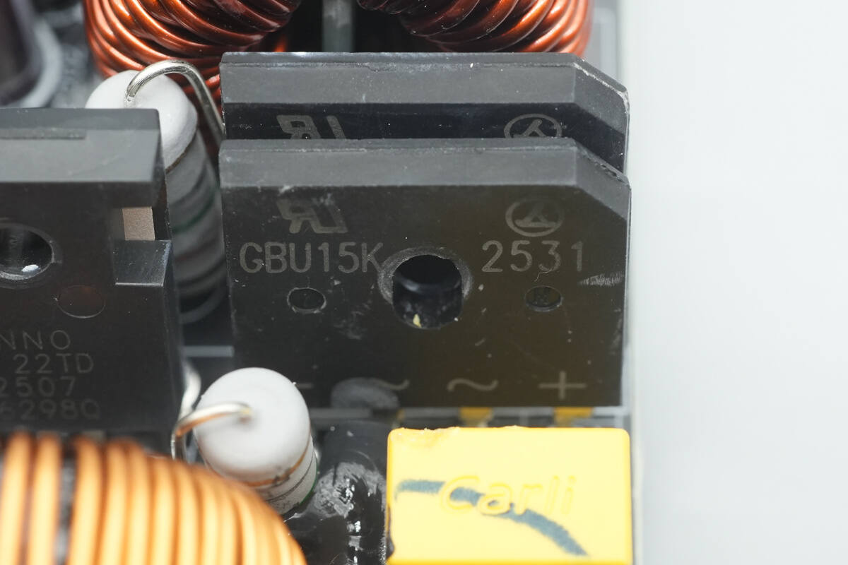
The bridge rectifier is from LRC, model GBU15K, rated at 800V 15A, and comes in a GBU package.
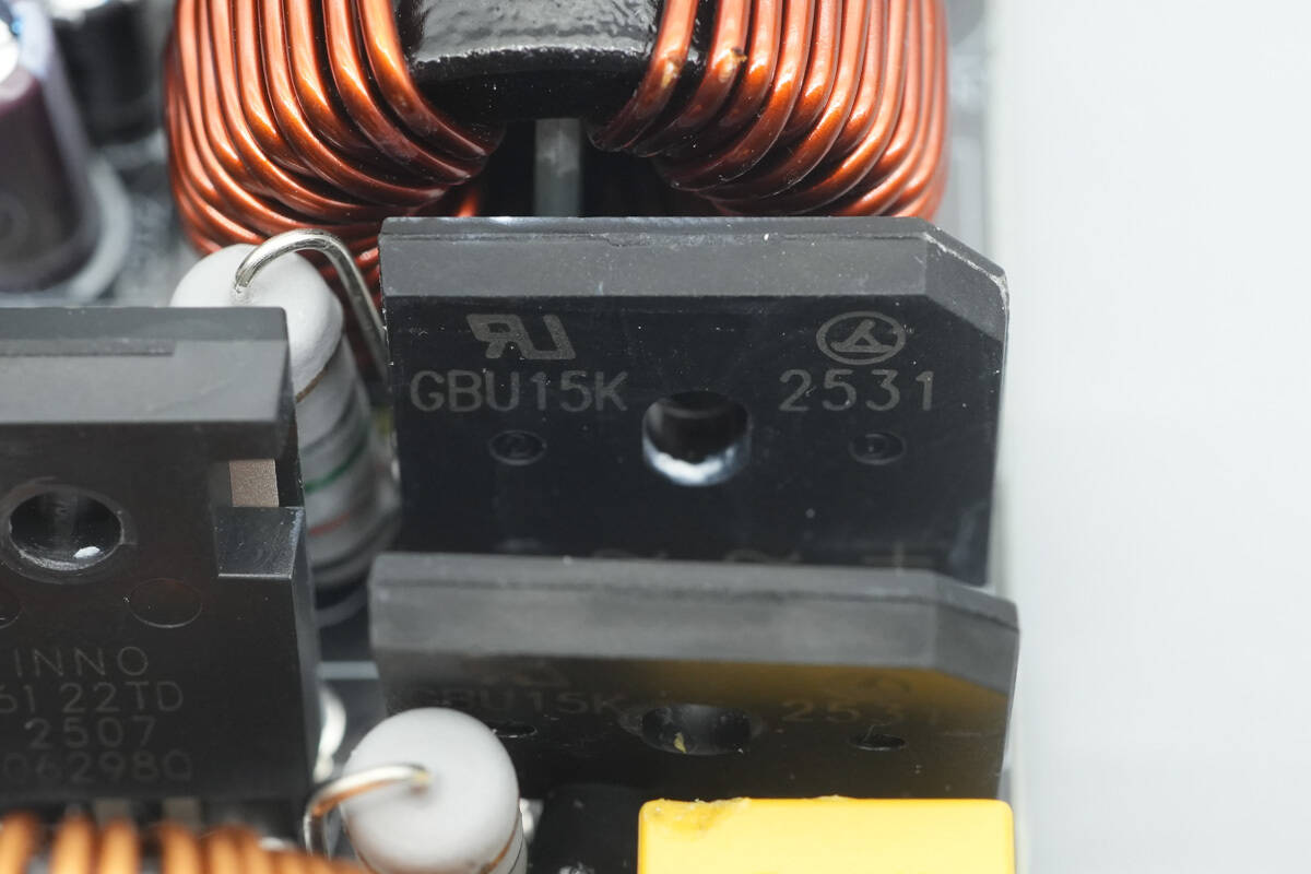
The other bridge rectifier has the same model, and the two bridge rectifiers are connected in parallel to share heat dissipation.

The film capacitor is from Carli, rated at 1 µF 450 V.
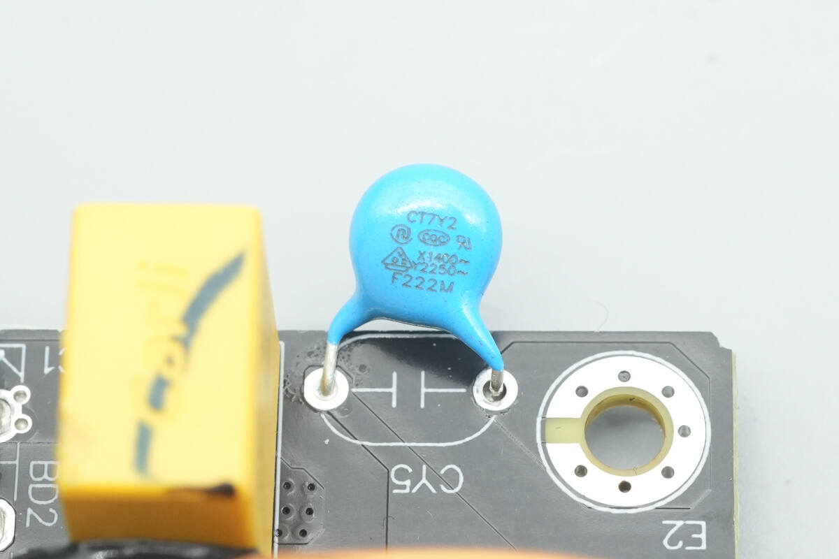
Close-up of the blue Y capacitor.
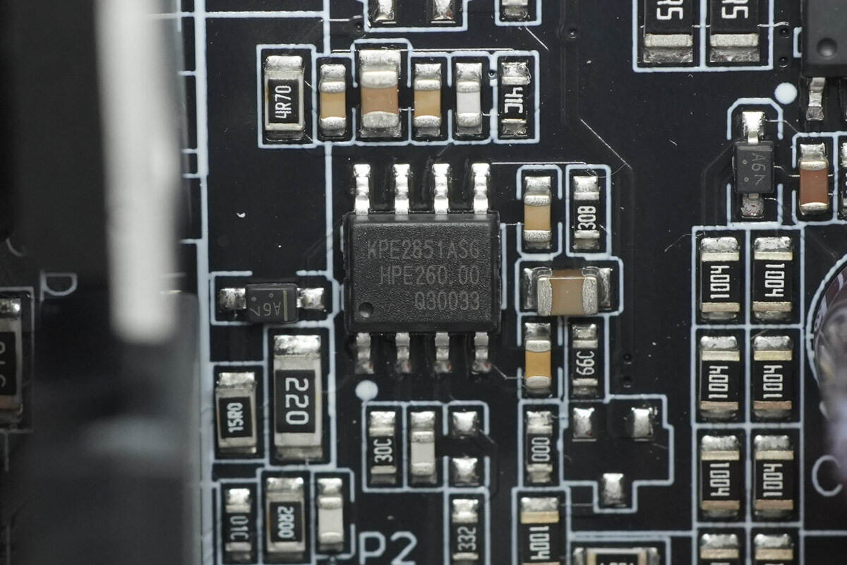
The PFC controller is from Kiwi Instruments, model KPE2851A. It is a high-performance boost PFC controller that operates in CCM mode, offering high power factor, low current distortion, and excellent voltage regulation. The chip features comprehensive protection functions, including VDD over-/under-voltage protection, input under-voltage protection, output over-/under-voltage protection, cycle-by-cycle overcurrent protection, cycle-by-cycle overload protection, current-sense resistor open-circuit protection, and over-temperature protection. It comes in an SOP-8 package.
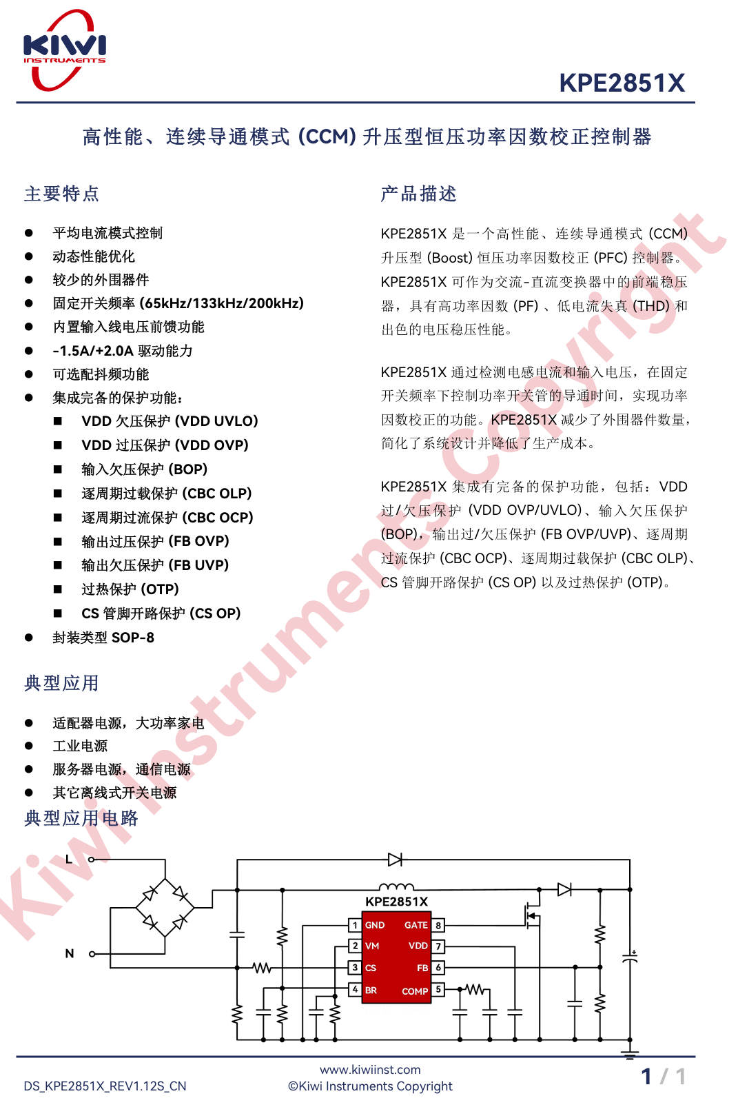
Here is the information about Kiwi Instruments KPE2851.
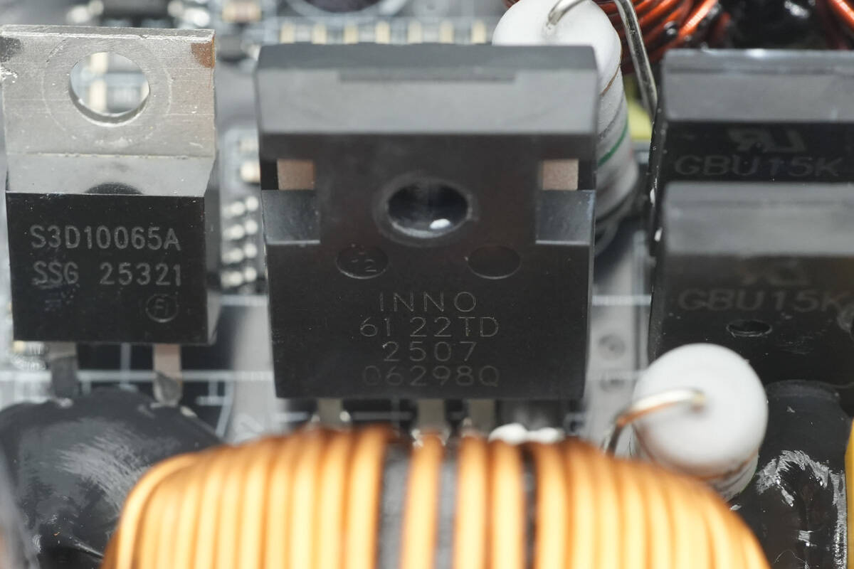
The PFC MOSFET is from Innoscience, model ISG6122TD. It is a GaN monolithic chip integrating a high-performance enhancement-mode GaN FET, rated for 700 V with an on-resistance of 30 mΩ and a transient voltage tolerance of up to 800 V. The device features an integrated gate driver supporting 10–24 V drive voltage, undervoltage lockout, and Miller clamping. It also supports short-circuit protection, multi-device parallel operation, and switching frequencies up to 2 MHz.
The ISG6122TD is suitable for high-power switching power supplies, including AC-DC, DC-DC, and DC-AC converters, half-bridge and full-bridge converters, data center/AI server PSUs, air conditioners, solar inverters, motor drives, onboard chargers (OBCs), and automotive DC-DC converters. It comes in a TO-247-4L package.
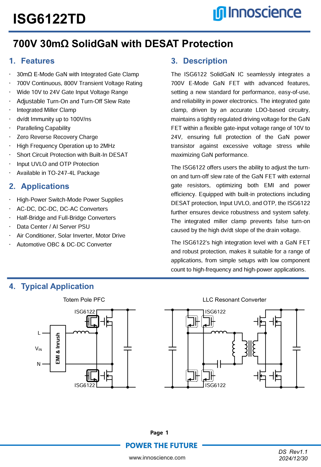
Here is the information about Innoscience ISG6122TD.
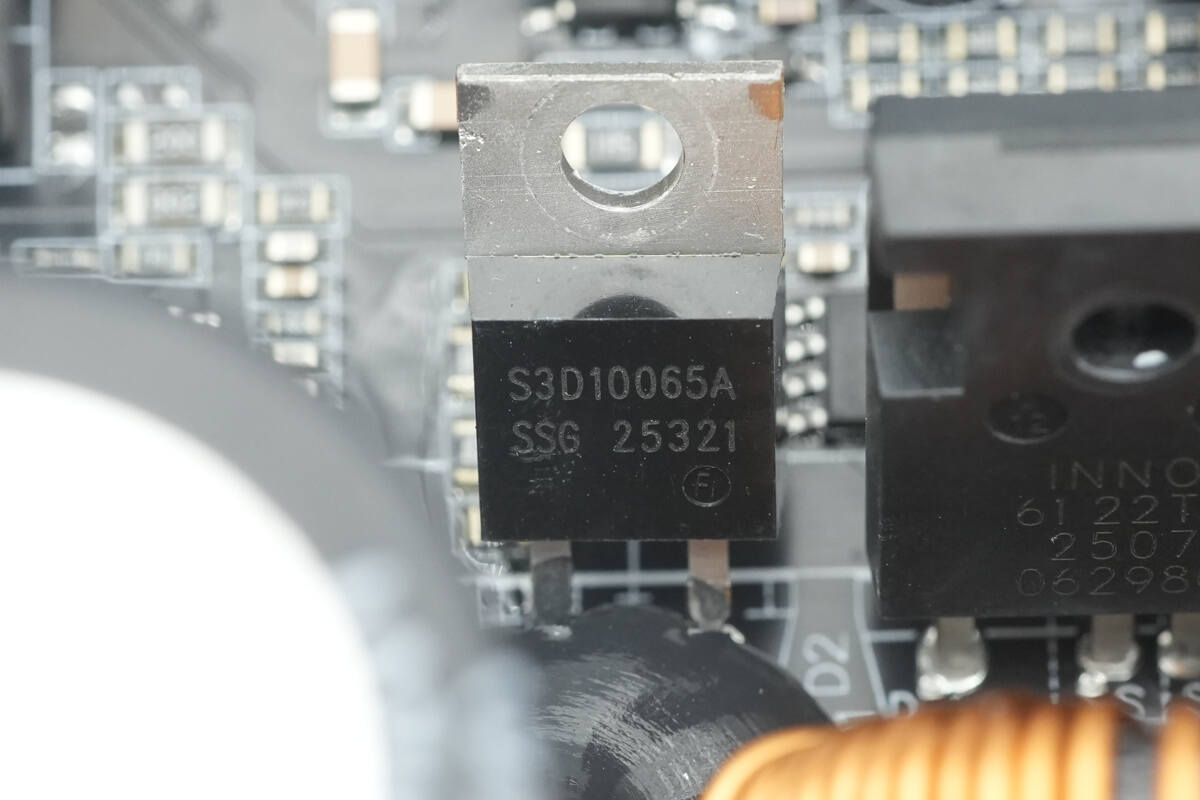
The PFC rectifier is from SMC, model S3D10065A. It is a SiC diode, rated at 10 A 650 V, and comes in a TO-220AC package.
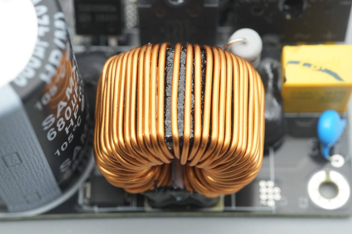
The PFC boost inductor is wound with enameled wire, with an insulating phenolic board installed at the bottom.
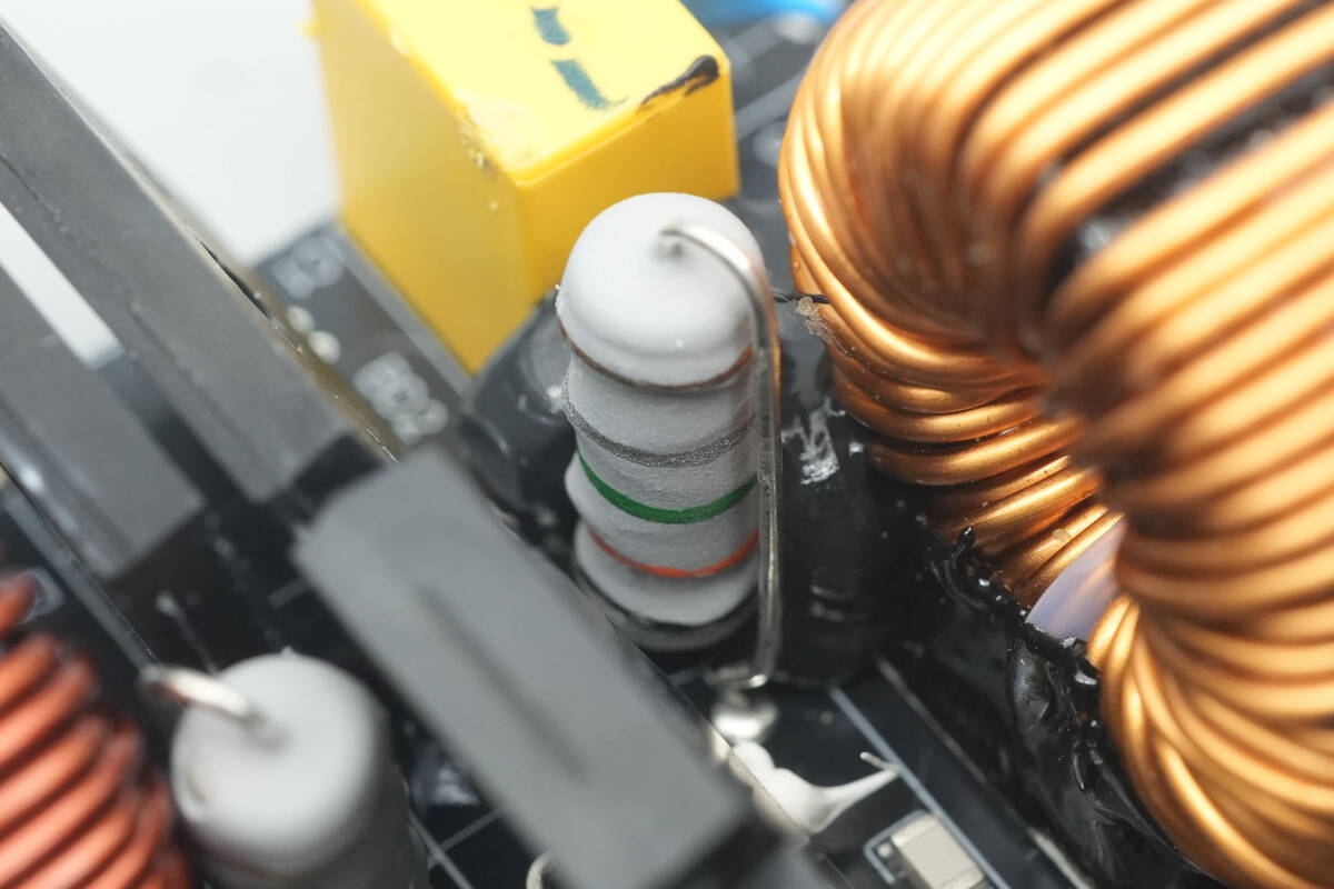
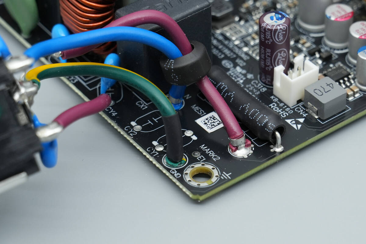
The color-coded resistor is used for current sensing of the PFC MOSFET.
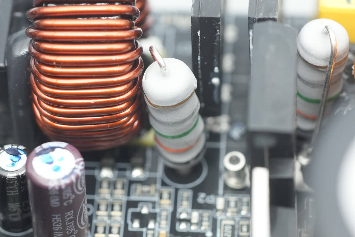
Another resistor is also used for current sensing of the PFC MOSFET.
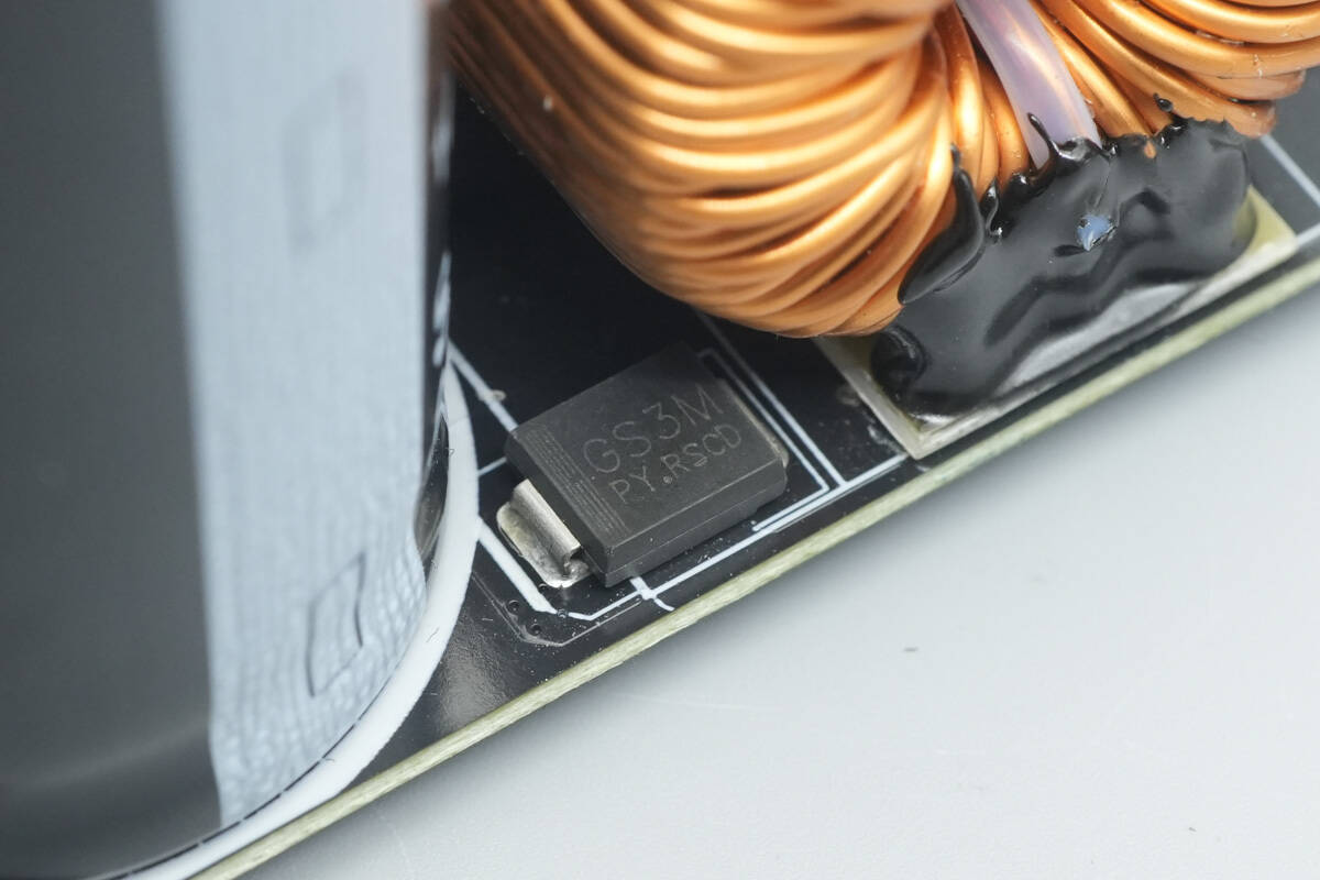
The bypass diode is of model GS3M.
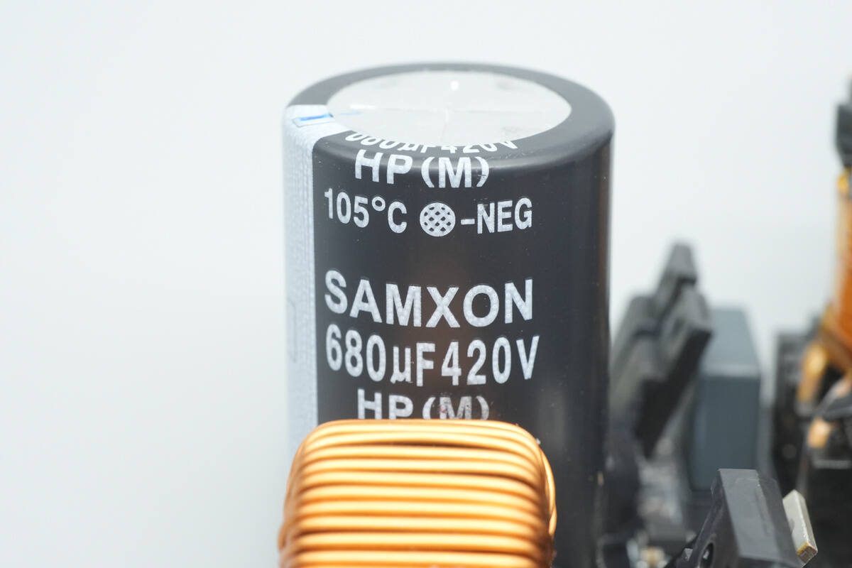
The high-voltage filter capacitor is from SAMXON, part of the HP series of wide-temperature electrolytic capacitors, rated for 105 °C operation, with a specification of 680 µF 420 V.
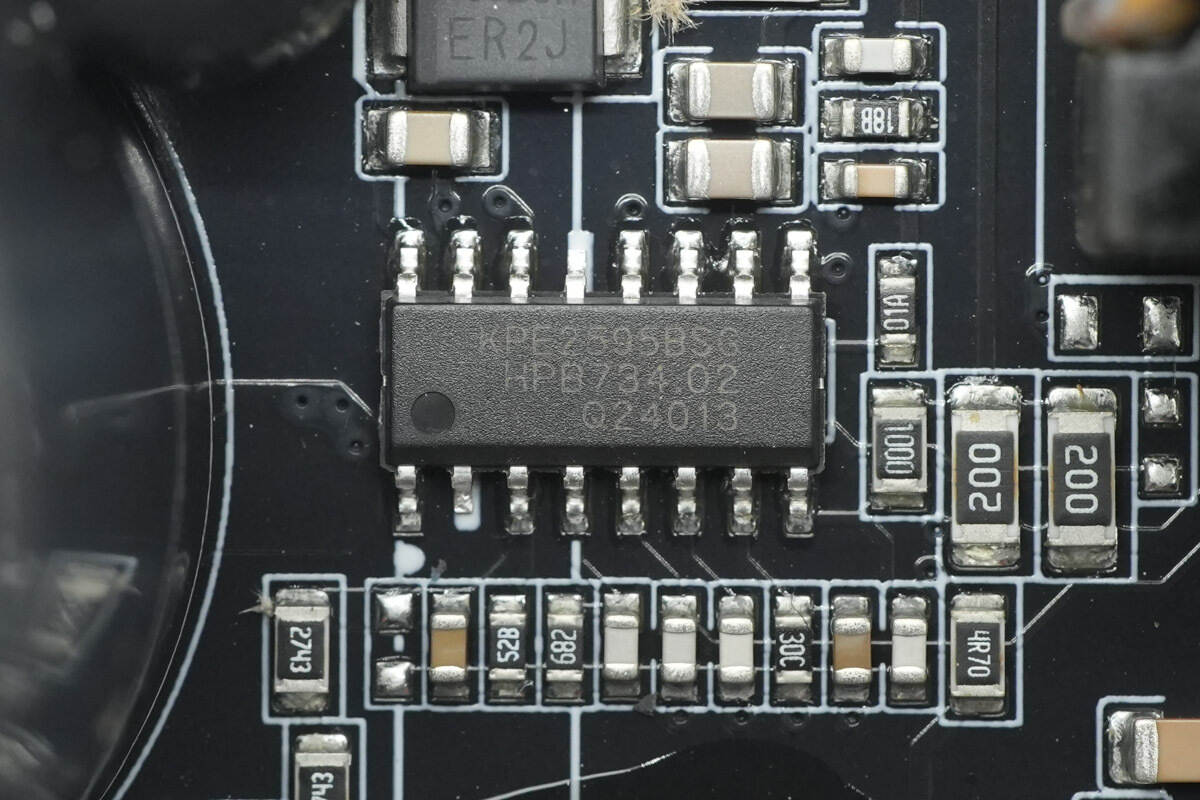
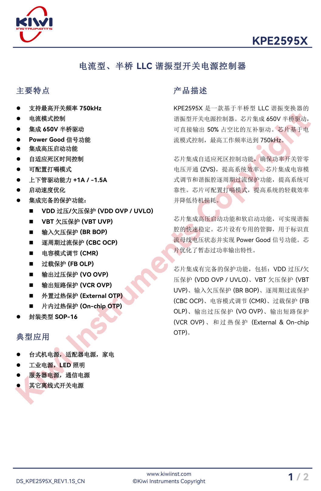
The LLC controller is from Kiwi Instruments, model KPE2595B. It is a half-bridge LLC controller with integrated high-voltage startup, operating in current-mode control and featuring a 650 V-rated half-bridge driver that supports switching frequencies up to 750 kHz. The chip includes adaptive dead-time control and provides a PowerGood signal output.
Internally, the KPE2595B integrates VDD over/under-voltage protection, VBT under-voltage protection, input under-voltage protection, cycle-by-cycle overcurrent protection, capacitor-mode regulation, overload protection, output over-voltage protection, output short-circuit protection, external over-temperature protection, and internal chip over-temperature protection. It comes in an SOP-16 package and is suitable for desktop, industrial, and server power supply applications.
Here is the information about Kiwi Instruments KPE2595B.
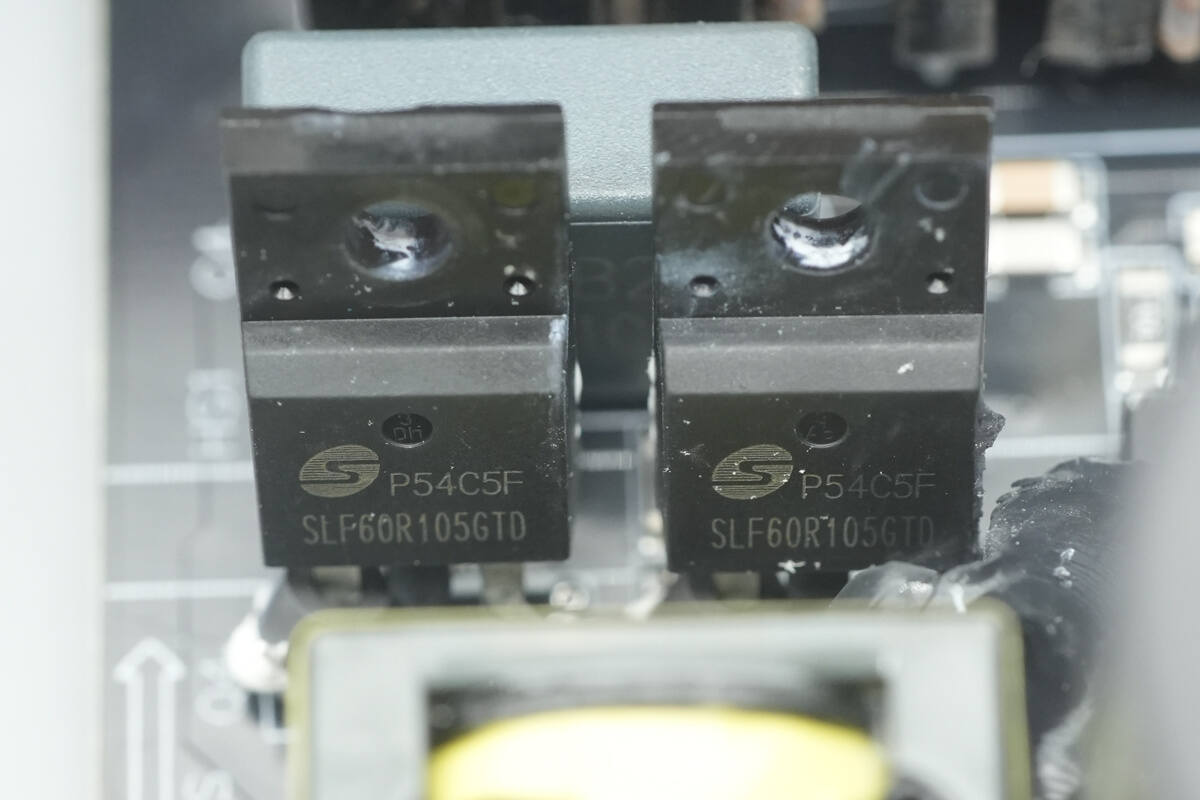
The LLC MOSFETs are from Msemitek, model SLF60R105GTD. They are NMOS devices rated for 600 V with an on-resistance of 93.5 mΩ, and come in a TO-220F package.
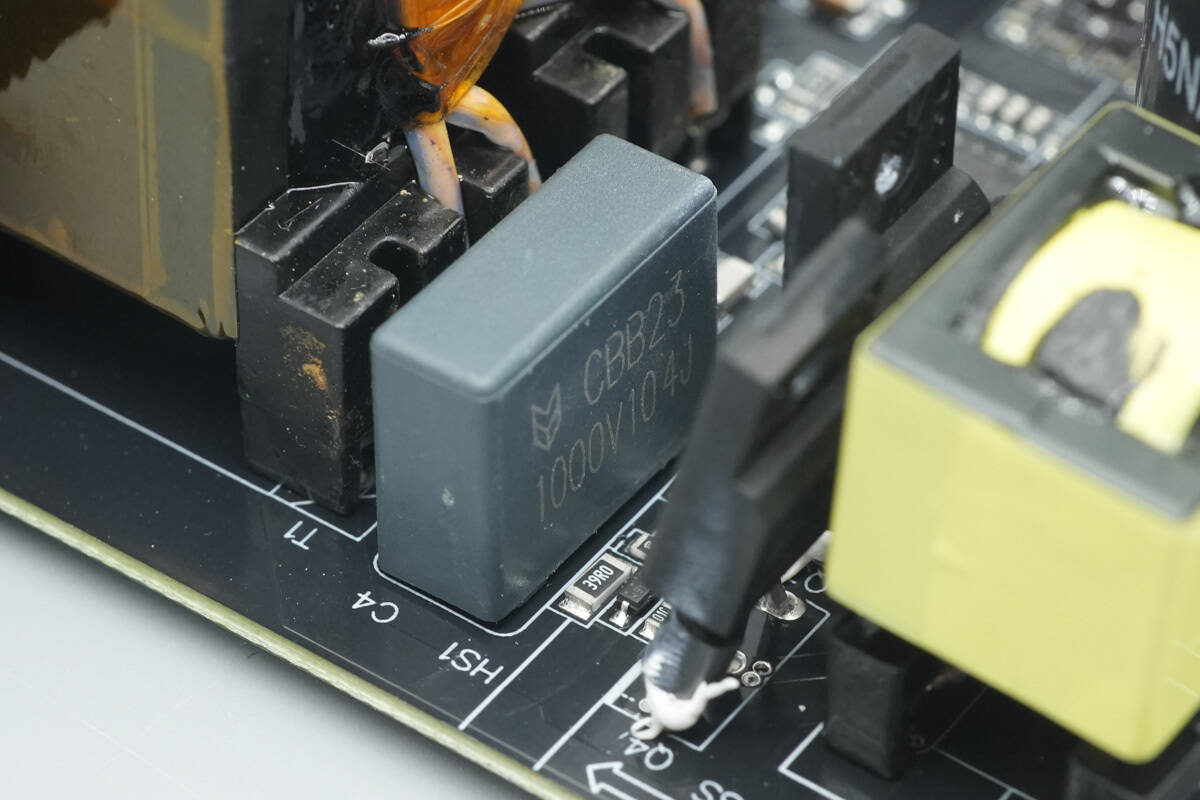
The resonant capacitor is rated at 0.1 µF 1000 V.
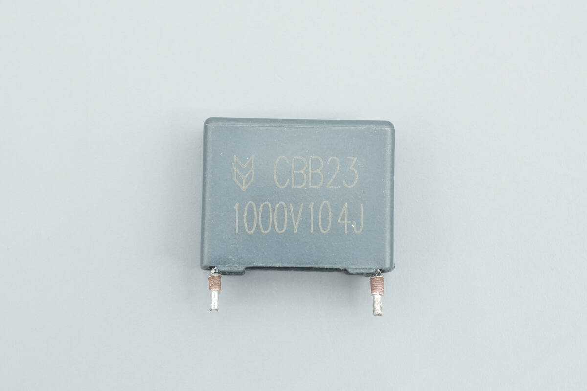
The other resonant capacitor has the same rating.
The resonant inductor is insulated with tape wound around the magnetic core.
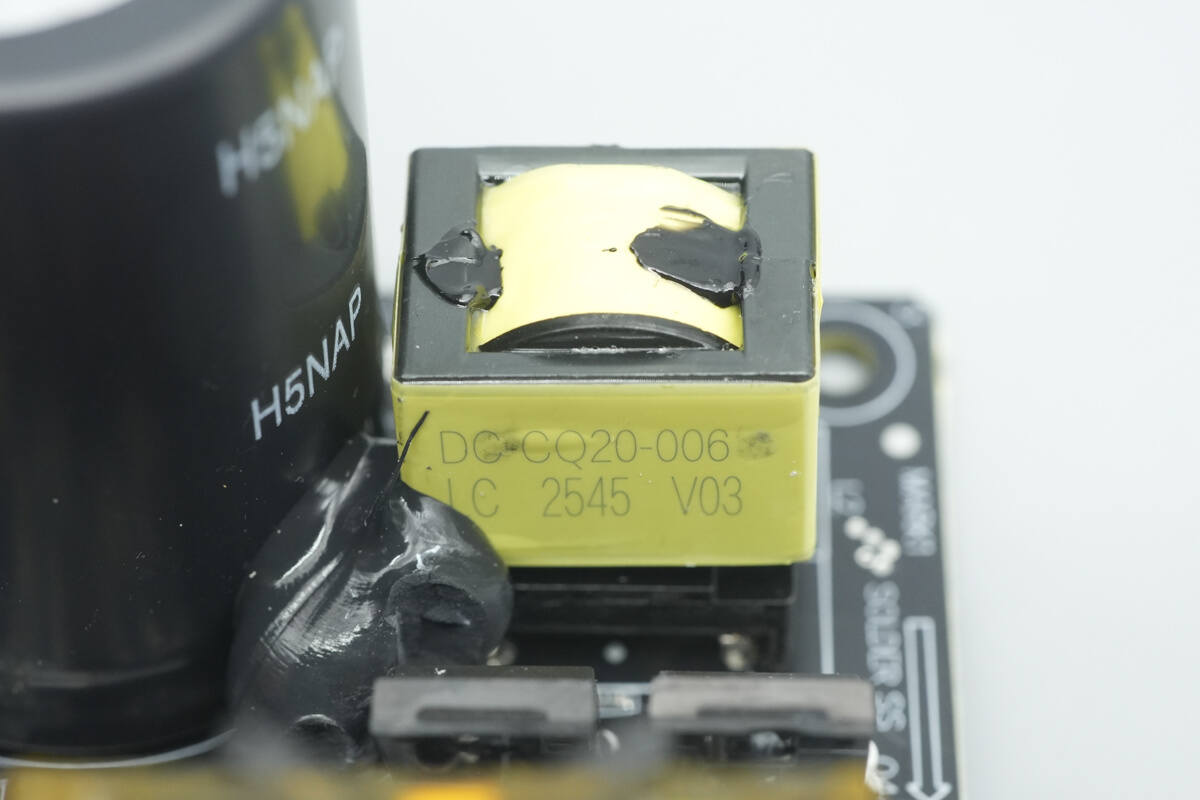
The transformer is wound with multi-layer insulated wire and copper strips, and the magnetic core is insulated with high-temperature tape.

The LITEON LTV-817 optocoupler is used for feedback communication.
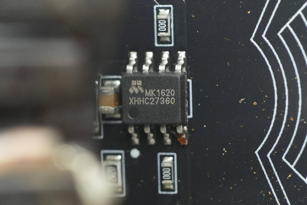
The synchronous rectifier controller is from Meraki, model MK1620. It is a dual-channel controller designed for LLC resonant topology. The chip supports a wide VCC supply range of 4.6–36 V and features ultra-low quiescent current. It provides a 10 ns fast turn-off propagation delay, includes a clamping circuit, supports dual-channel VDS differential input detection, dual-channel logic interlock, and adaptive drive control. The device comes in an SOP-8 package.
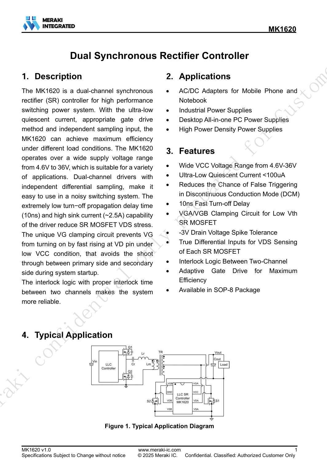
Here is the information about Meraki MK1620.
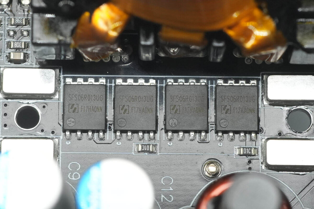
The synchronous rectifiers are from Tongwei, model SFS06R013UGF. They are NMOS devices rated for 60 V with an on-resistance of 1.6 mΩ, and come in a PDFN 5×6 package.
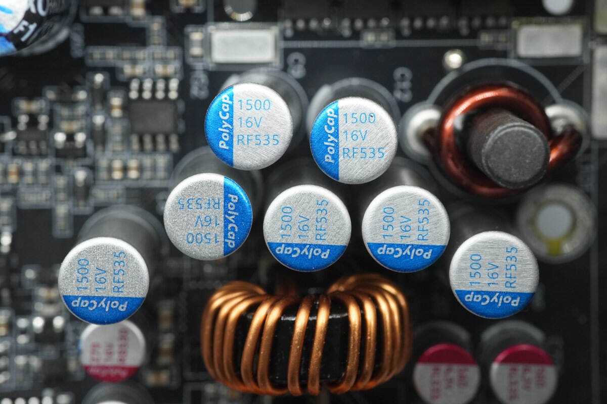
The filter capacitors are from PolyCap, part of the RF series of solid-state capacitors. They feature a long lifespan of 5000 hours and high-frequency, low-impedance characteristics. Each capacitor is rated at 1500 µF 16 V, and seven units are connected in parallel.
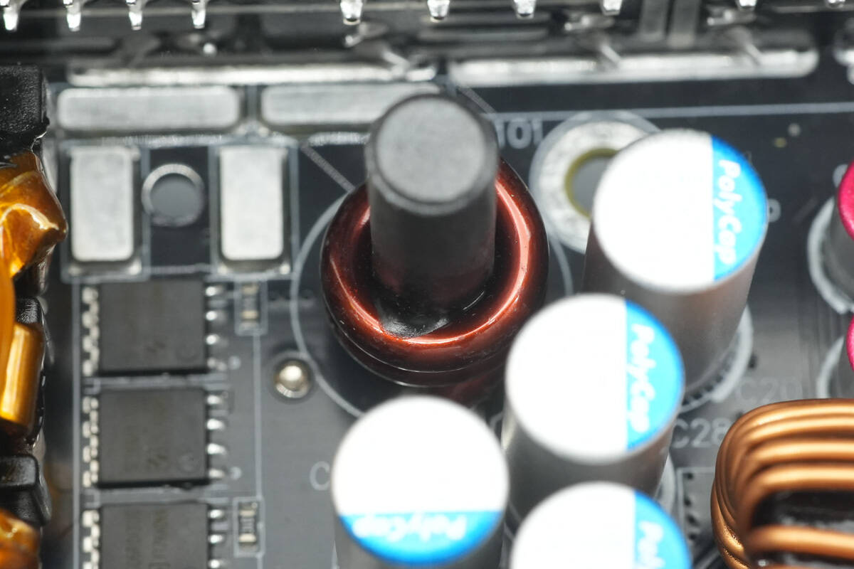
The output filter inductor is wound with enameled wire.
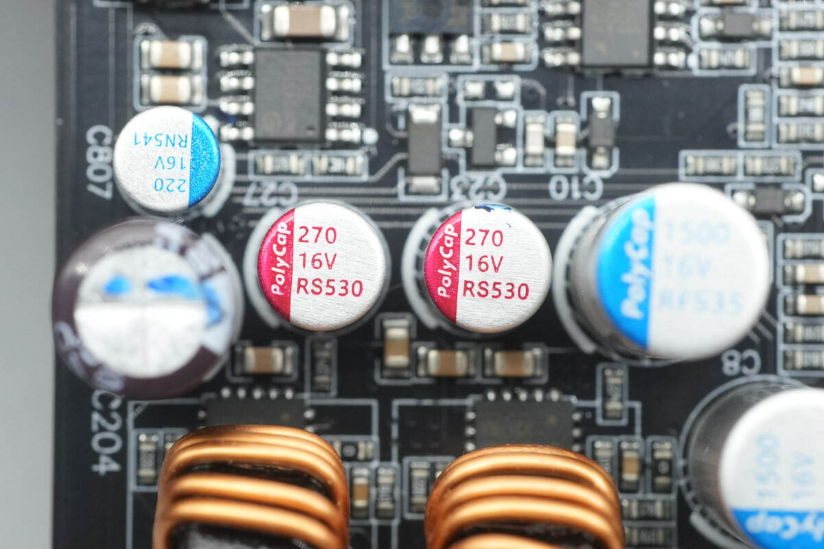
The two filter capacitors are from PolyCap, part of the RS series of solid-state capacitors, each rated at 270 µF 16 V.
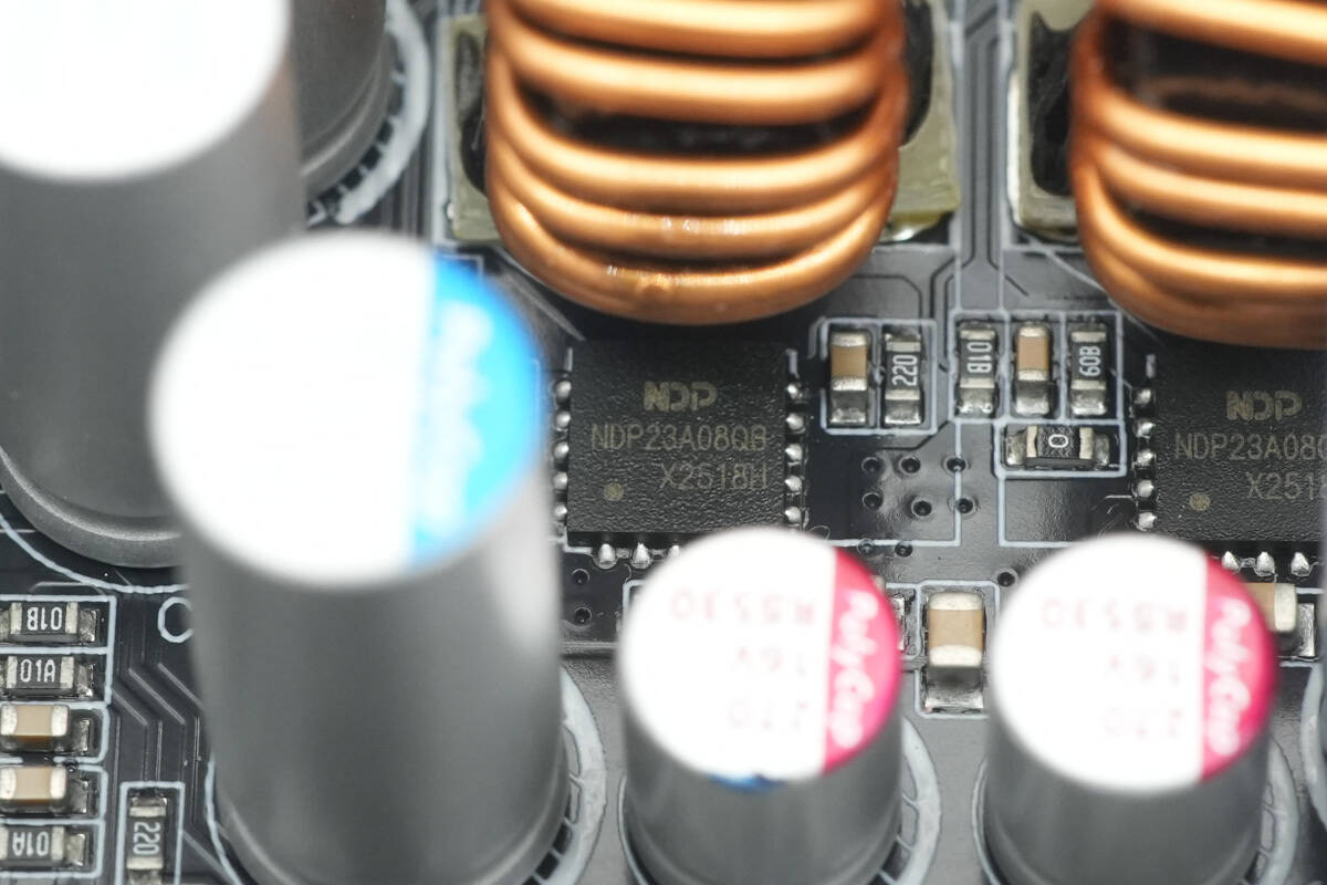
The buck controller is from NDP, marked NDP23A08QB. It integrates a MOSFET internally and comes in a QFN 5×5 package.
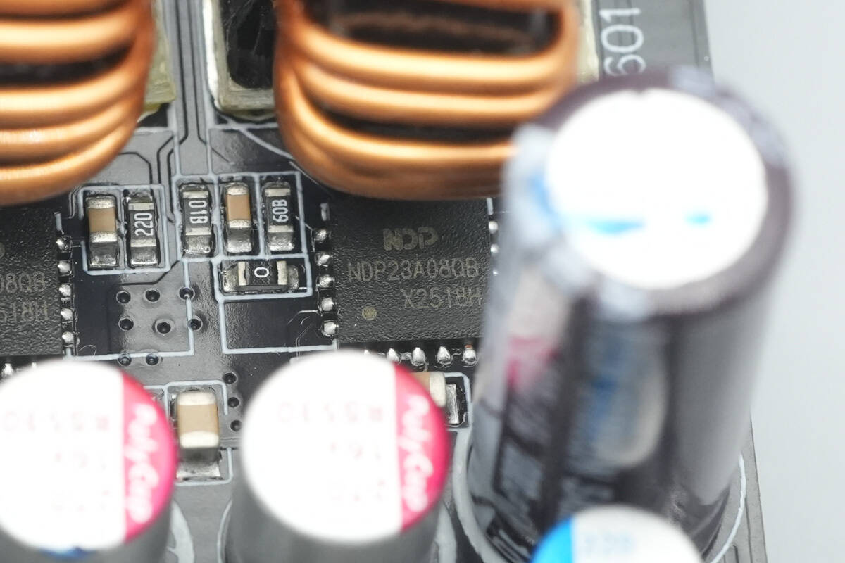
The other buck controller has the same model and is used for the 3.3 V/5 V power supply output.
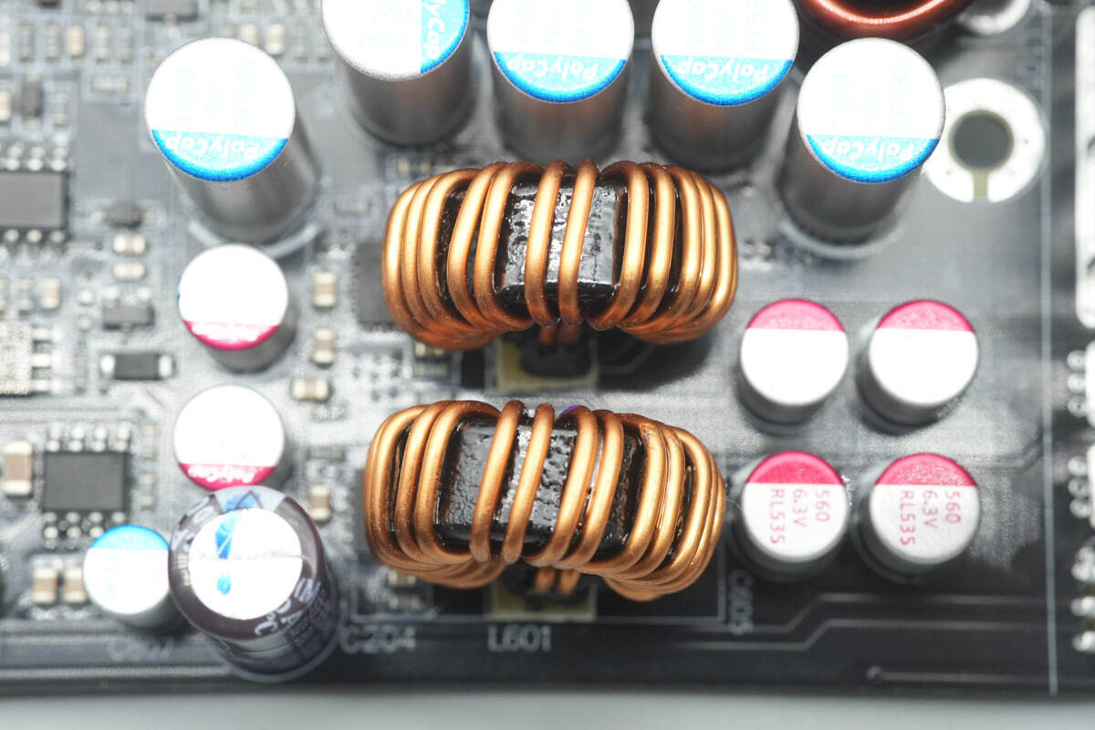
The buck inductors are wound with enameled wire, with insulating phenolic boards installed at the bottom.

The filter capacitors are from PolyCap, part of the RL series of solid-state capacitors, each rated at 560 µF 6.3 V.
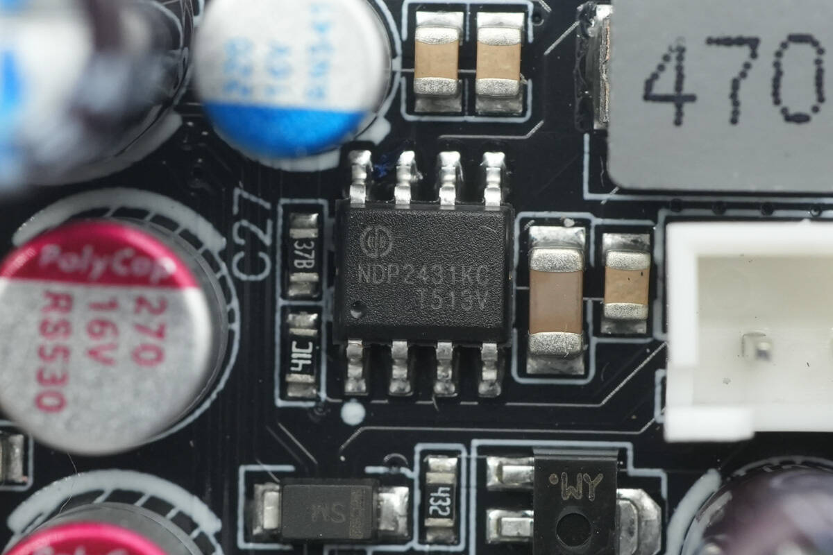
The power conversion chip is from NDP, model NDP2431KC, and comes in an SOP-8 package.

Close-up of the 47 µH alloy inductor.
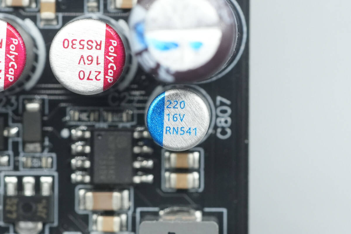
The filter capacitor is rated at 220 µF 16 V.
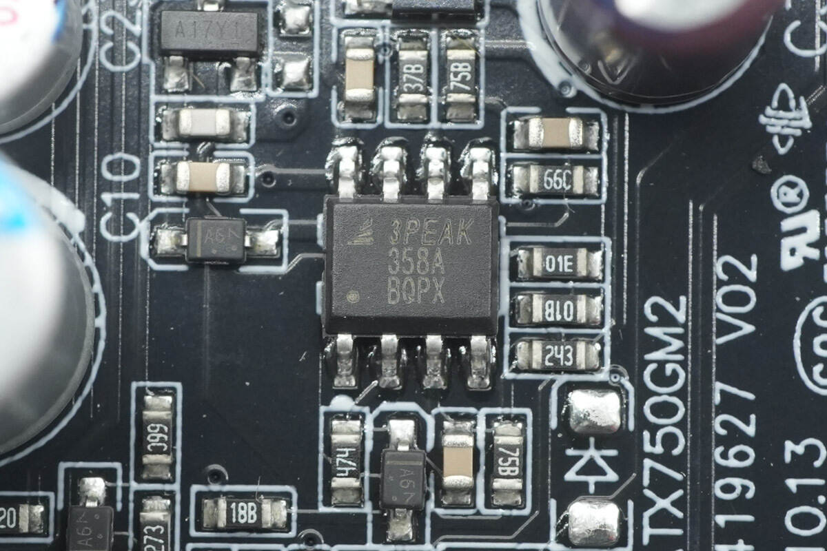
The operational amplifier is from 3PEAK, model LM358A. It features low offset, low power consumption, and stable frequency response, and comes in an SOP-8 package.
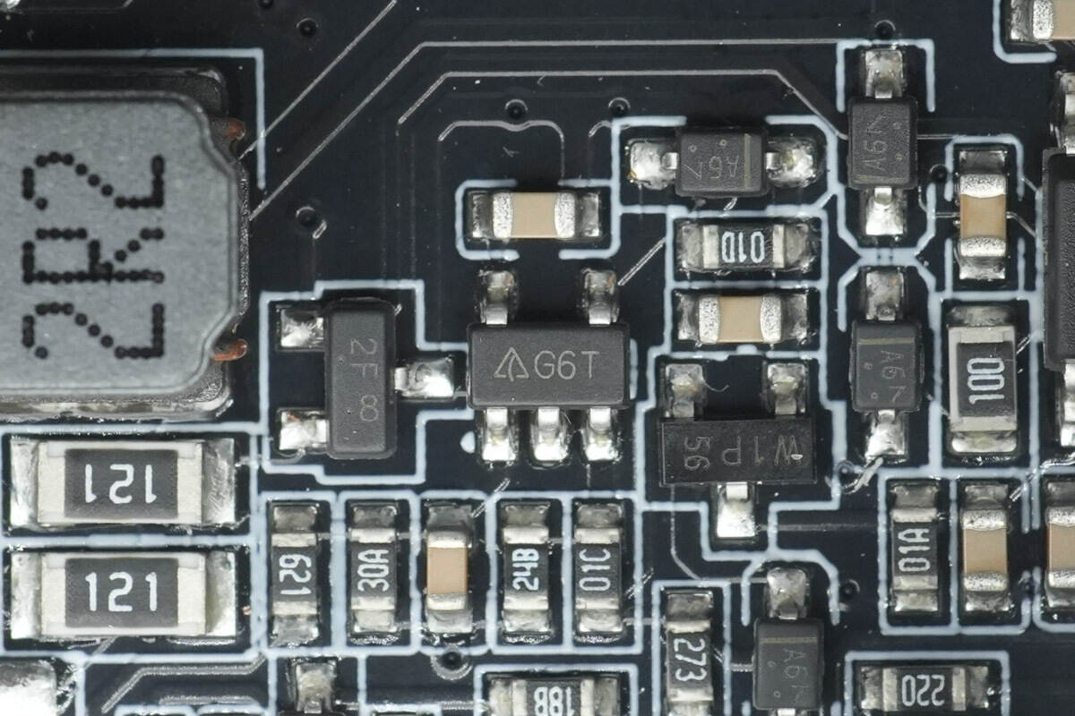
The operational amplifier is from DIODES, marked G6T, model AS321. It is a low-power single op-amp and comes in a SOT-25 package.
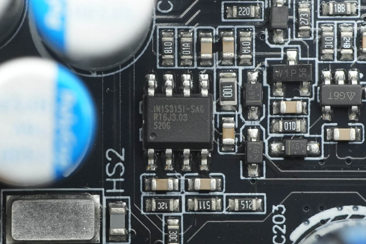
The power management chip is from Infsitronix, model IN1S315I-SAG. It provides over-voltage and under-voltage protection for 3.3 V, 5 V, and 12 V rails, and comes in an SOP-8 package.
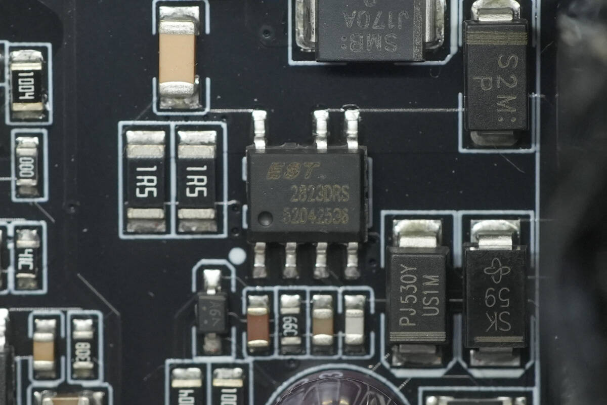
The standby power chip is from EST, marked EST.2823, and comes in an SOP-7 package.
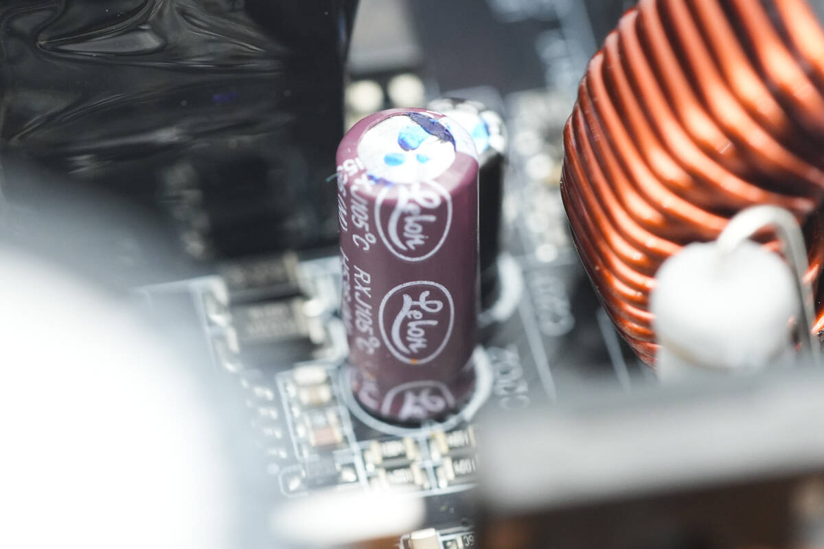
The filter capacitor is from Lelon.
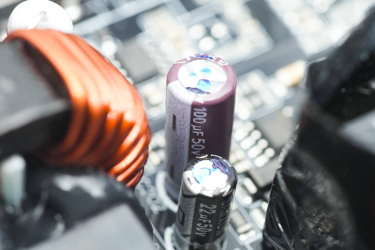
The specification is 100μF 50V.

The other filter capacitor is from SAMXON and is rated at 22μF 50V.
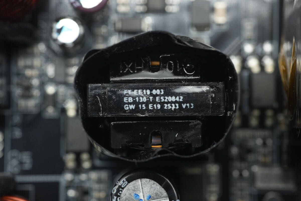
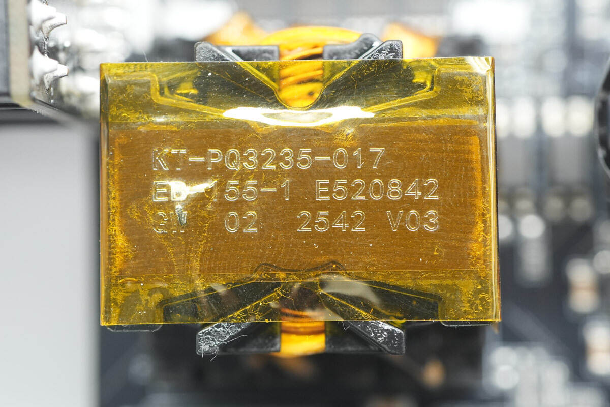
The standby power transformer is tightly wound and insulated with tape.
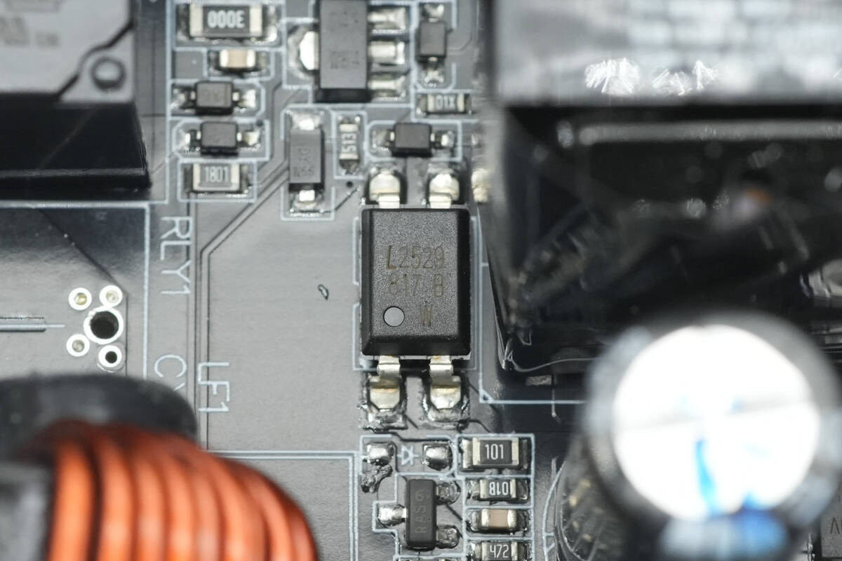
The LITEON LTV817 optocoupler is used for output voltage feedback.
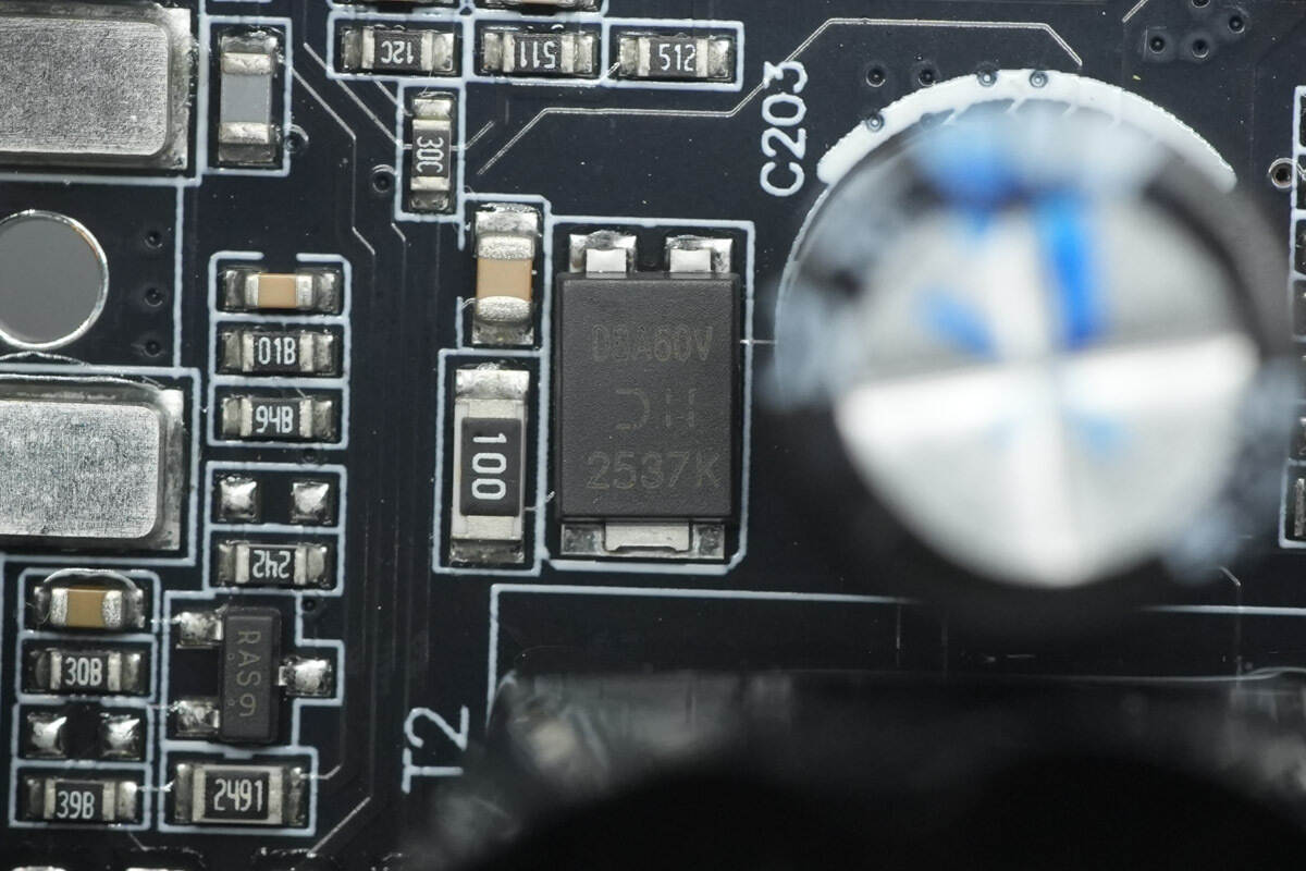
The rectifier is from DIODES, marked D8A60V, model SDT8A60VP5. It is a Schottky diode rated at 60V 8A and comes in a PowerDI5 package.
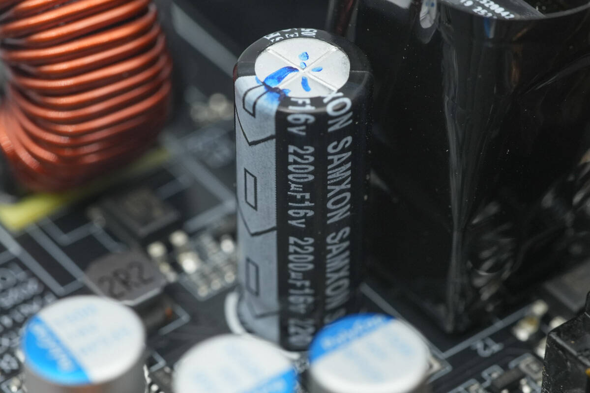
The filter capacitor is from SAMXON and is rated at 2200μF 16V.
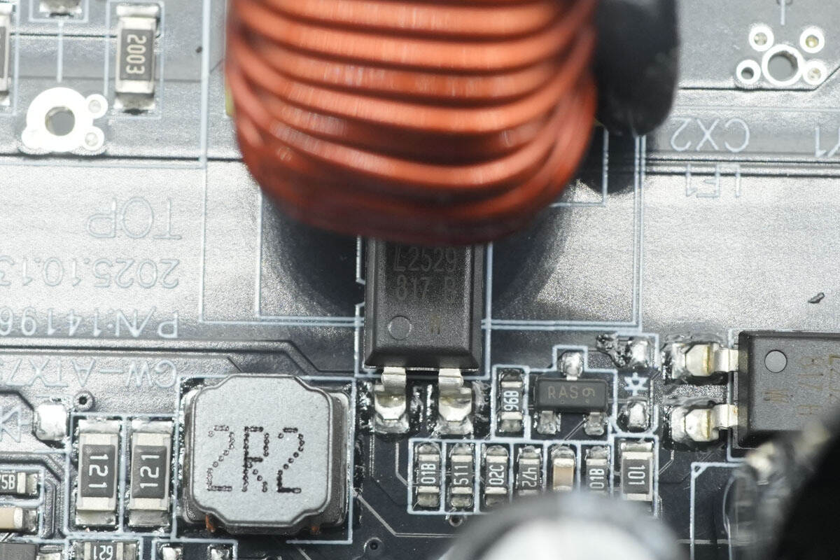
The LITEON LTV817 optocoupler is used for AC detection.
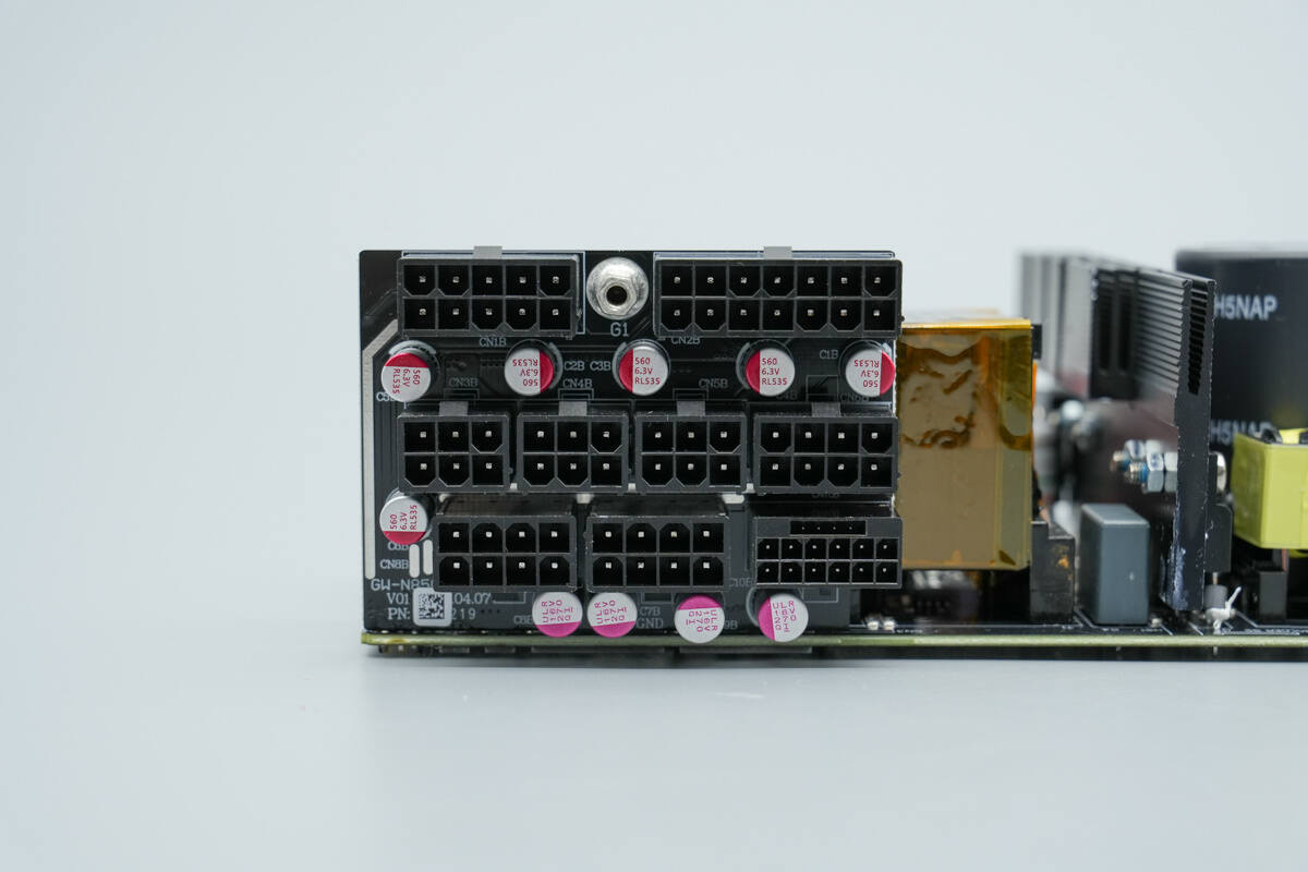
The small output PCB is soldered with filter capacitors.
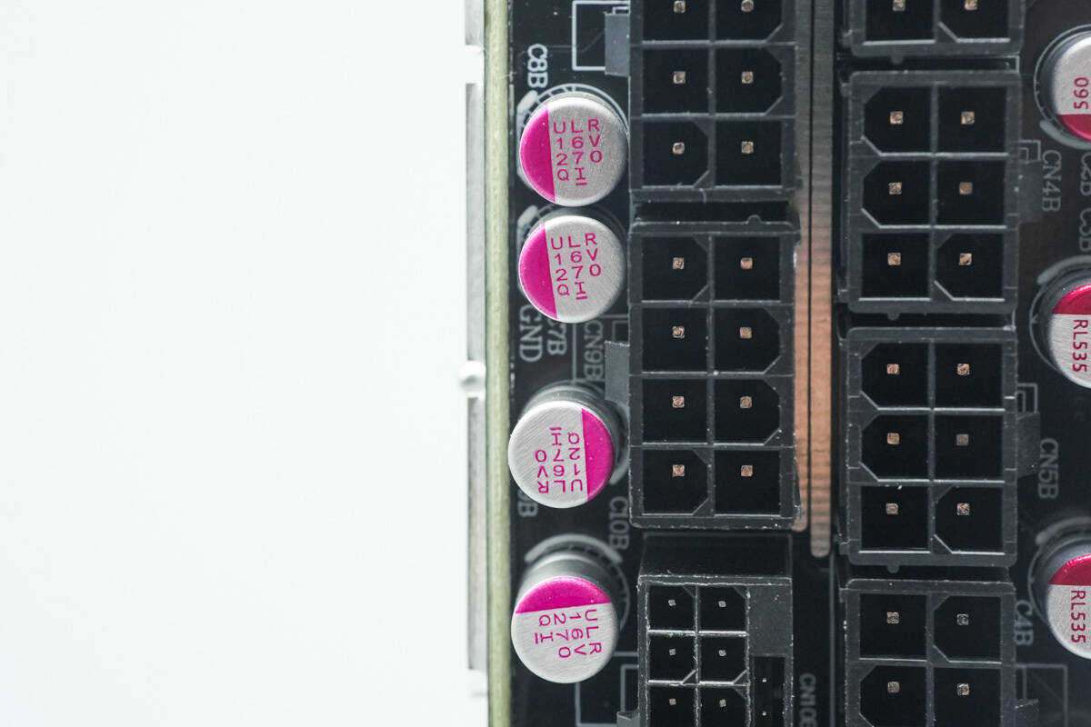
The filter capacitors are from SAMXON, part of the ULR series solid-state capacitors, with a specification of 16V 270μF.
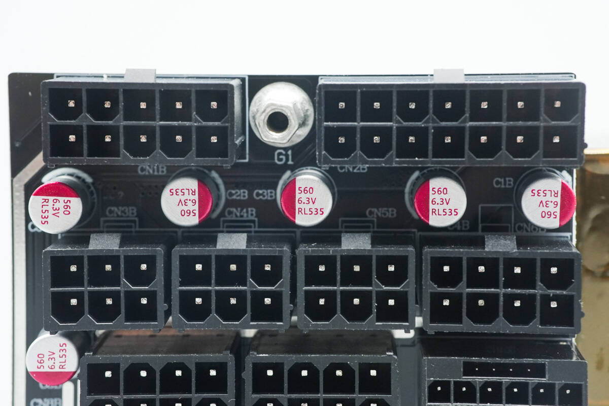
The filter capacitors are from PolyCap with a specification of 560 μF, 6.3 V.

Well, those are all components of the GreatWall SPARK 850W GaN 80 PLUS Gold Fully Modular Power Supply.
Summary of ChargerLAB
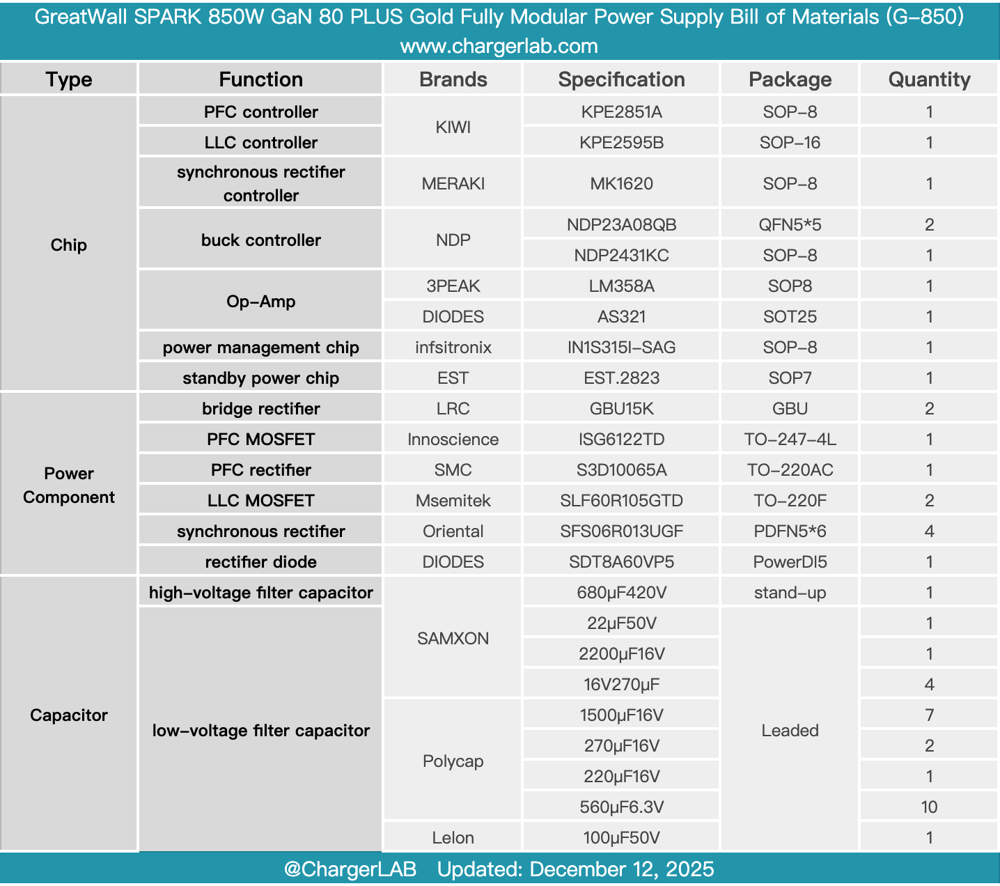
Here is the component list of the GreatWall SPARK 850W GaN 80 PLUS Gold Fully Modular Power Supply for your convenience.
It features a fully modular cable design, complies with the ATX 3.1 standard, and provides a native 12V 2×6+2 PIN interface. Certified with 80 PLUS Gold, it utilizes an active PFC + half-bridge LLC + synchronous rectification + DC-DC mainstream high-efficiency architecture, offering a single 12V rail with high current output to meet the power requirements of high-performance platforms.
After taking it apart, we found that it uses a Kiwi Instruments KPE2851A PFC controller paired with a KPE2595B LLC controller. The PFC MOSFET employs Innoscience ISG6122TD GaN-on-Si chip, the PFC rectifier uses SMC S3D10065A SiC diodes, and the LLC MOSFETs are Msemitek SLF60R105GTD.
The synchronous rectifier controller is a Meraki MK1620, paired with Oriental SFS06R013UGF synchronous rectifiers. The DC-DC buck chips are from NDP, managed by Infineon control ICs. High-voltage capacitors are sourced from SAMXON, and the output solid-state capacitors are from PolyCap. The overall construction is solid and reliable.
Related Articles:
1. Teardown of Xiaomi 67W GaN Charger (MDY-19-EA)
2. Teardown of Gospower 3000W Switching Power Supply (G1236-3000WNA)
3. Teardown of CUKTECH 25 Power Bank SE (LPB252N)