Introduction
In this teardown, we will disassemble a 2200W 80 PLUS Platinum server power supply from GreatWall, model CRPS2200DLW. This power supply supports a wide input voltage range of 100–240V. When operating at 100–127V AC, the maximum output power is 1100W. At 200–240V AC or 240V DC input, it delivers the full rated output of 2200W.
The input side of the power module includes a cooling fan, a power socket, and an indicator light, while the output side is equipped with a gold finger connector. Internally, the power supply adopts an interleaved PFC and full-bridge LLC topology and uses controllers from TI. Let’s move on to the teardown and take a closer look at the internal design and components.
Product Appearance

The enclosure is secured with screws.
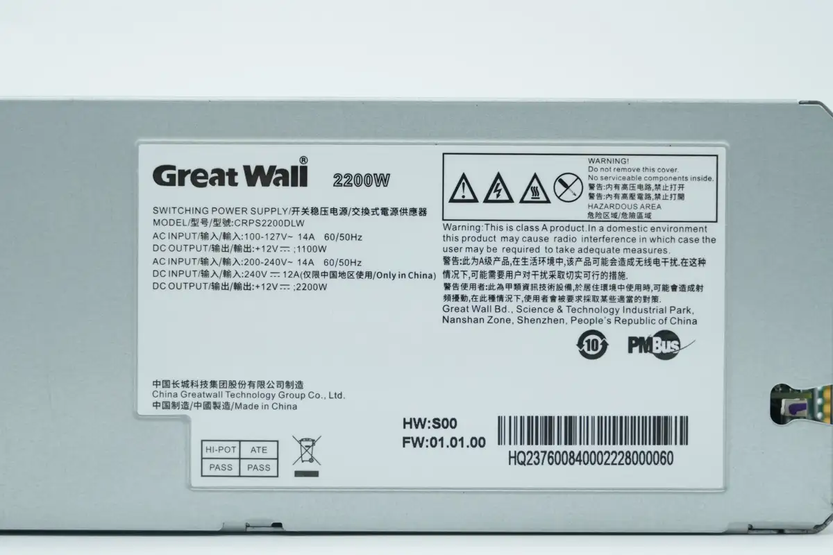
Model: CRPS2200DLW
AC Input: 100–127V\~ 14A 60/50Hz
DC Output: +12V; 1100W
AC Input: 200–240V\~ 14A 60/50Hz
DC Input: 240V 12A
DC Output: +12V; 2200W
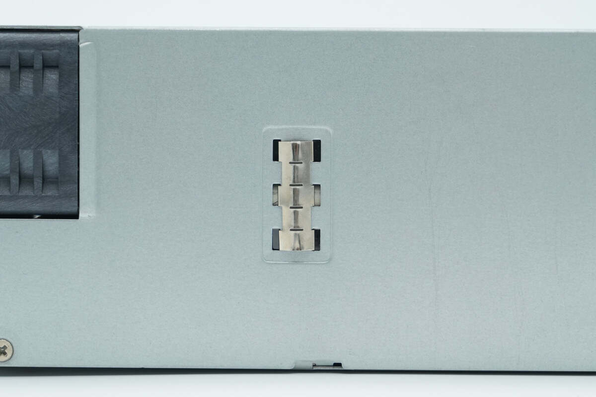
There is a grounding spring on the side.
The side is secured with screws and clips.
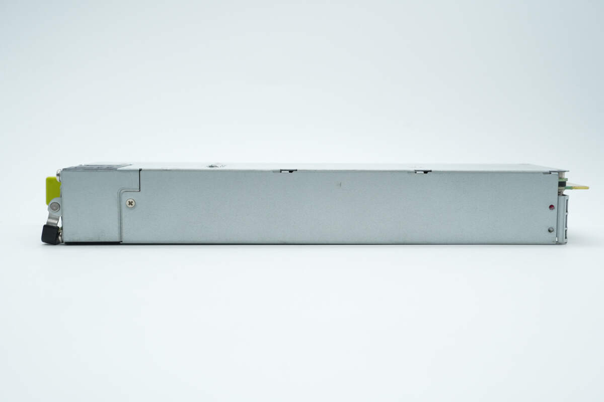
The other side is also secured with screws.
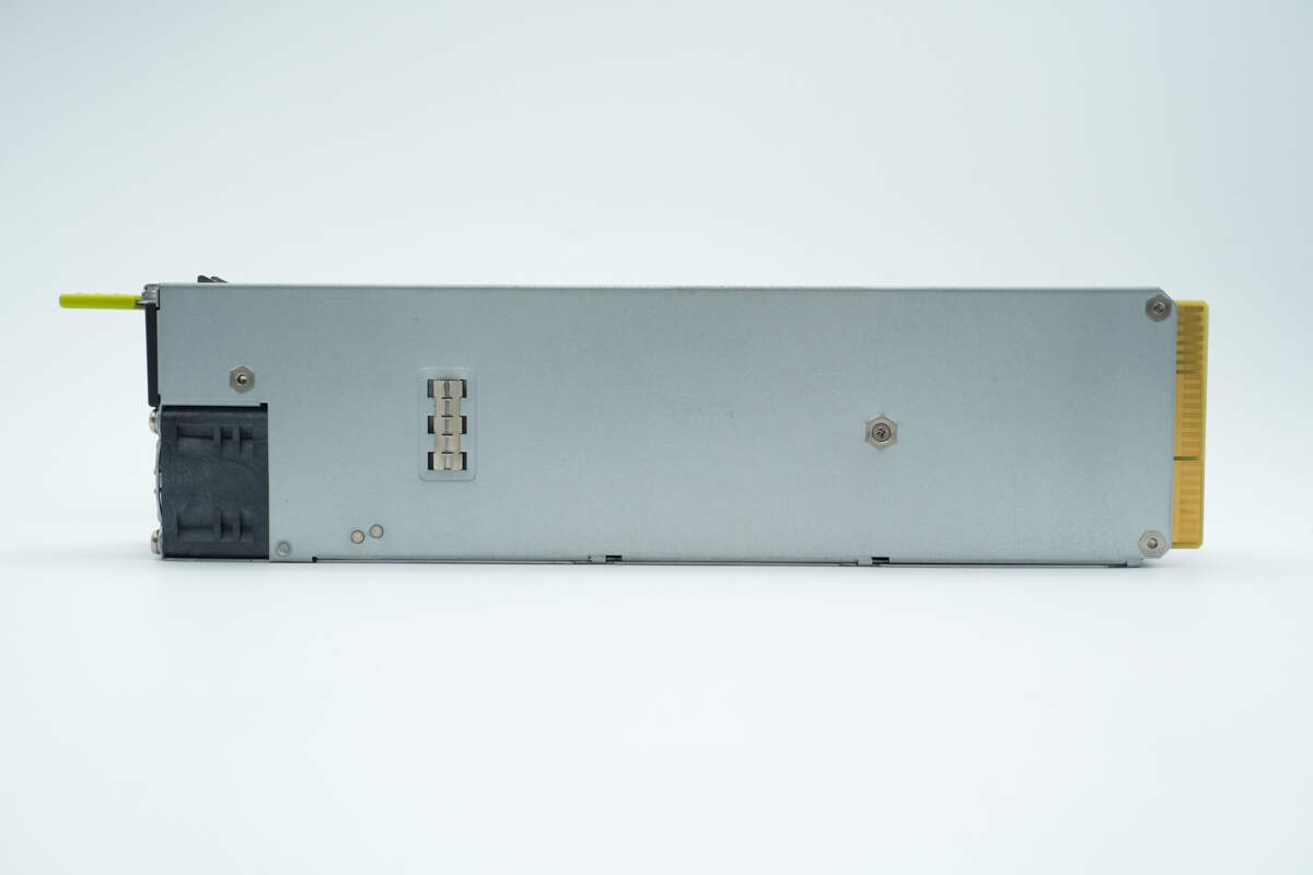
There is a grounding spring on the back side.
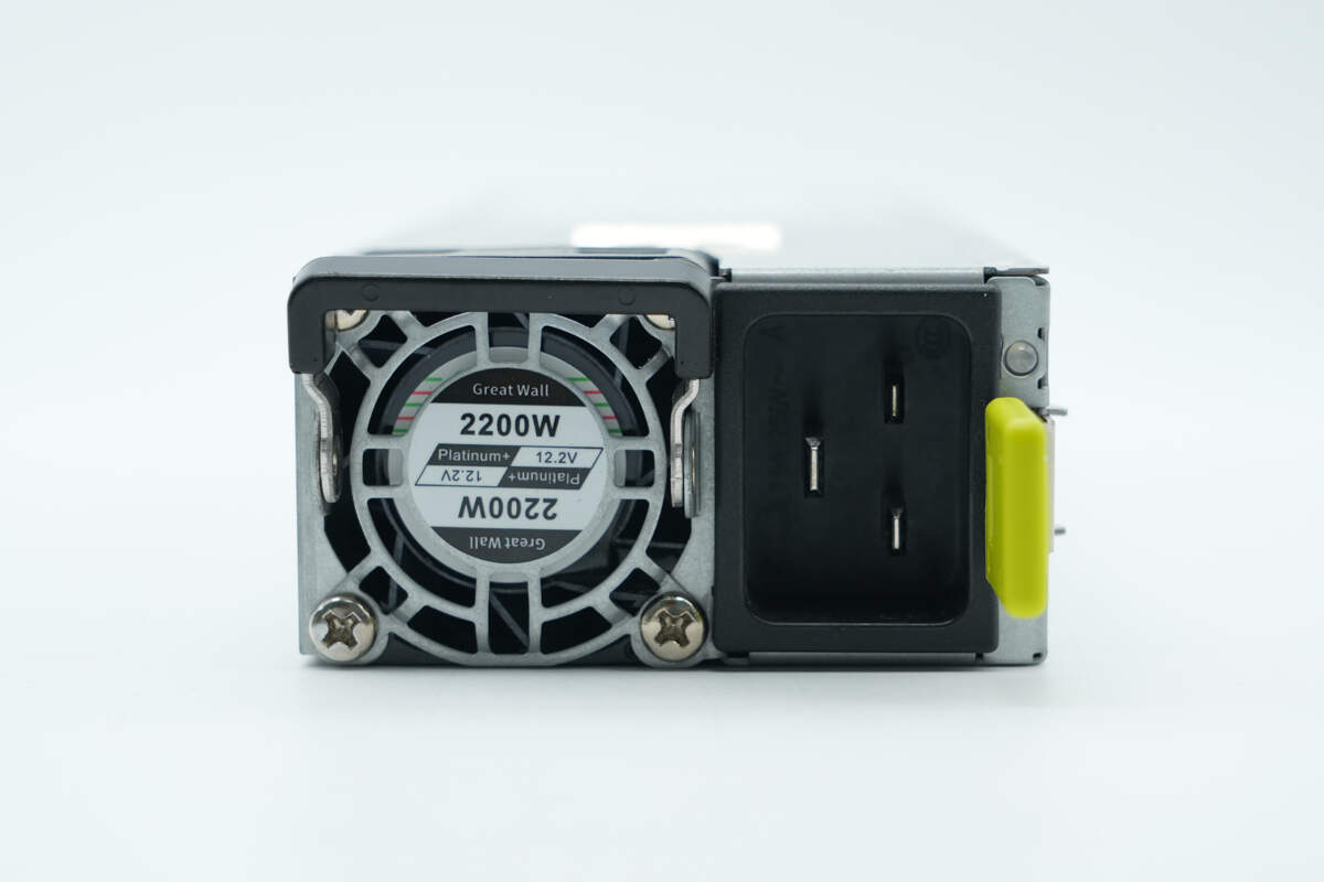
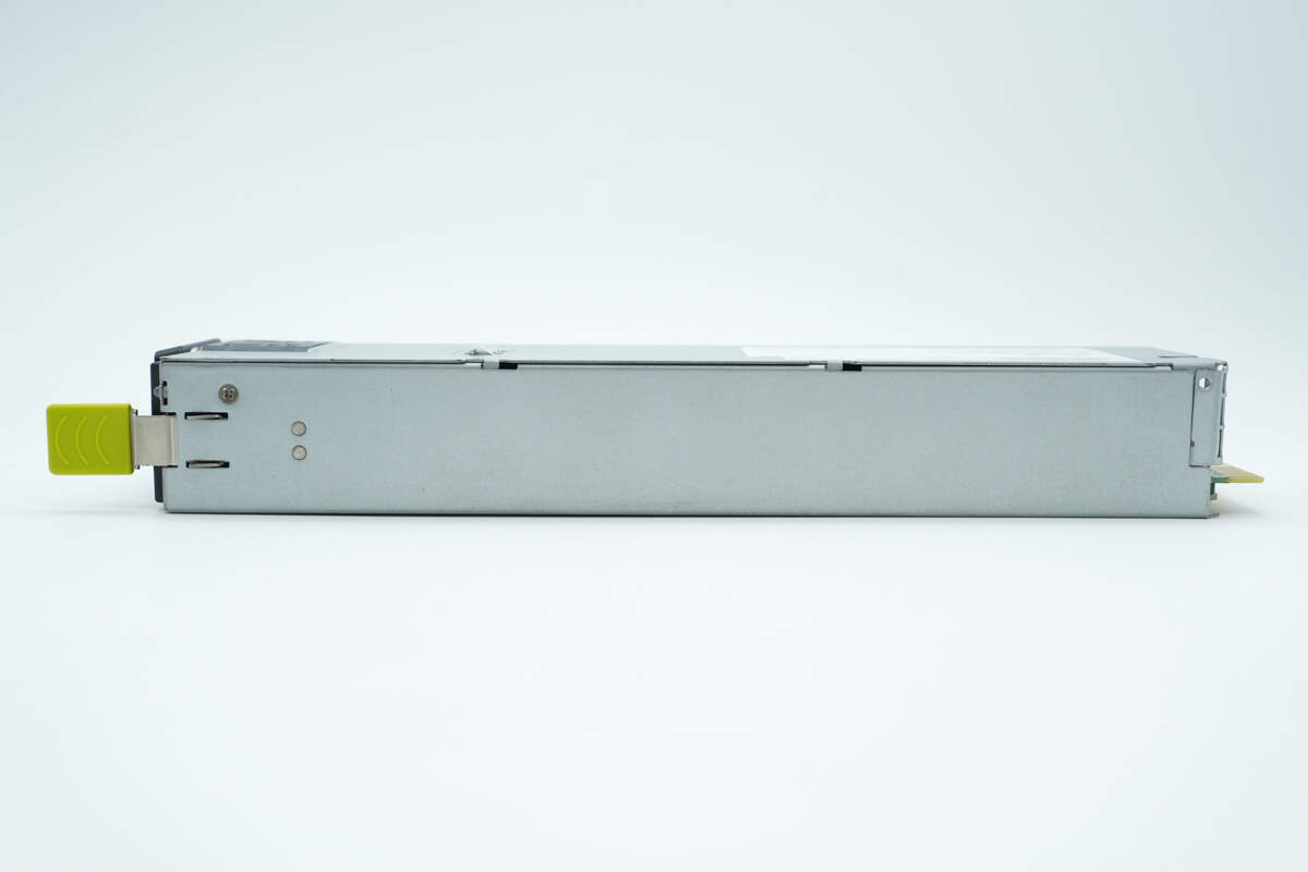
The input side features a handle, a cooling fan, an indicator, a C20 inlet, and a release latch.
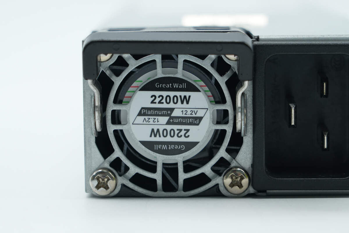
The cooling fan is manufactured by Great Wall. The power supply delivers an output power of 2200W with an output voltage of 12.2V.
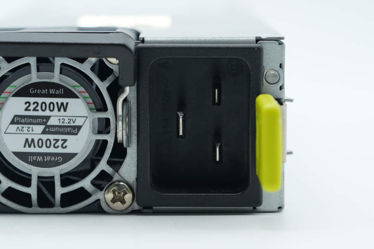
Close-up of the C20 inlet.
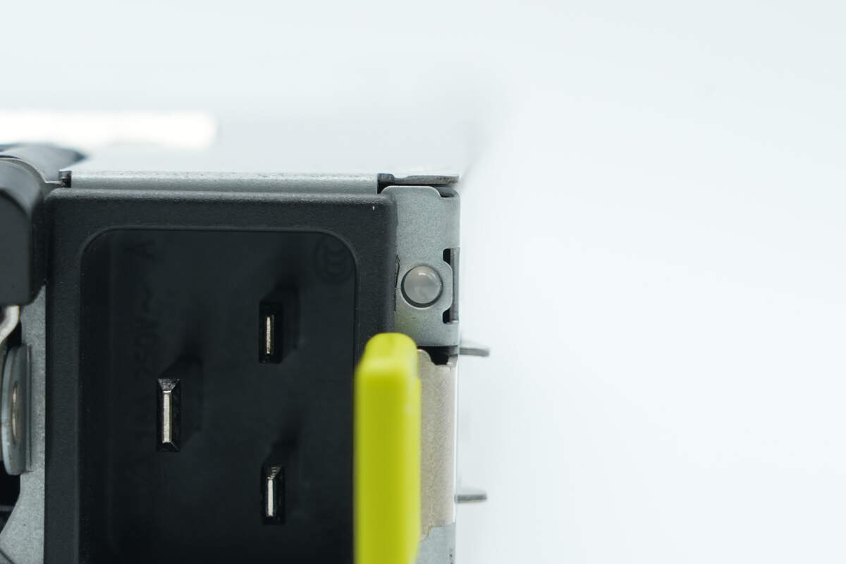
Close-up of the indicator.
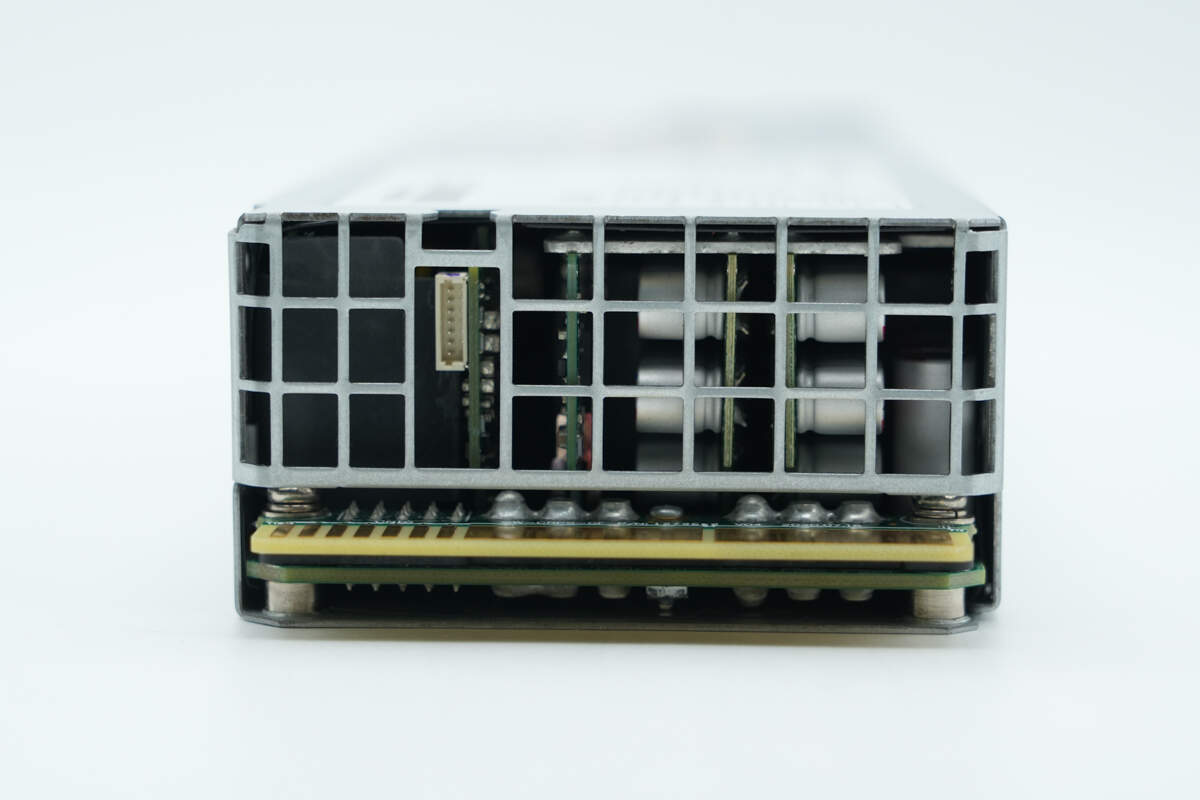
The output side has a grille for ventilation. The gold finger connector is soldered in place.
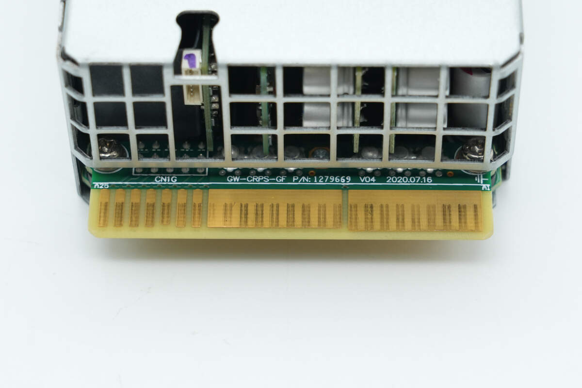
Close-up of the gold finger connector.
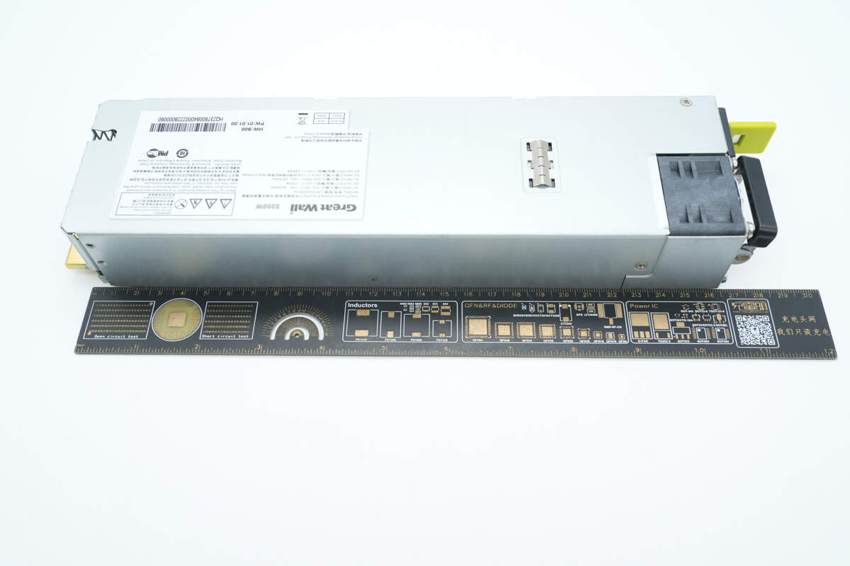
The length is about 265 mm (10.43 inches).
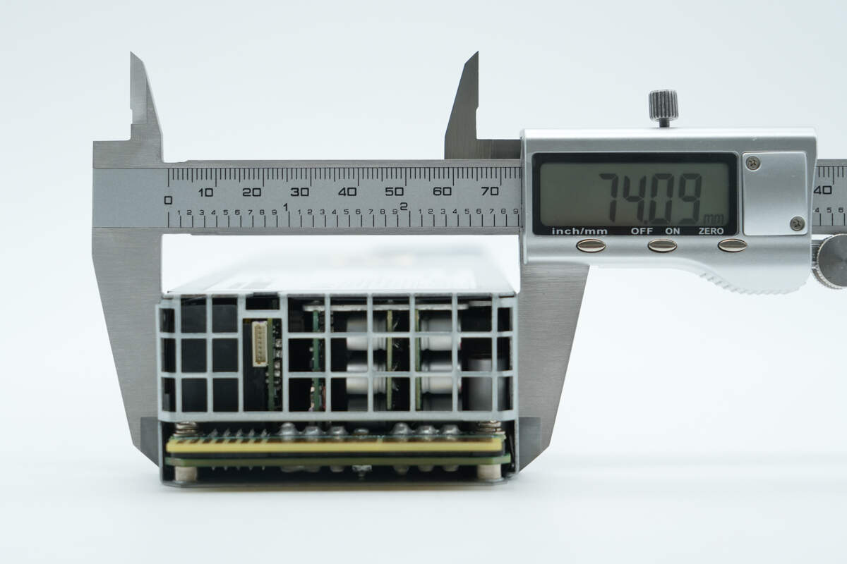
The width is about 74.1 mm (2.92 inches).
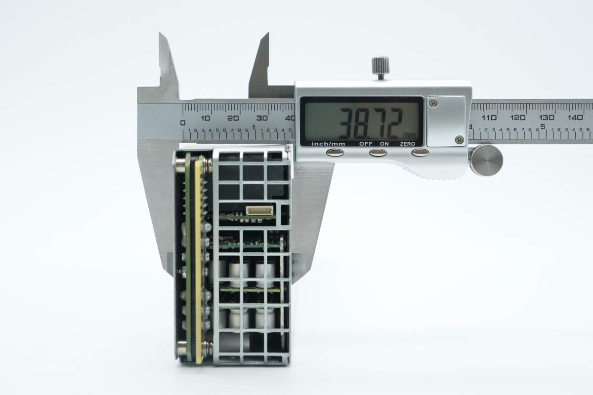
The thickness is about 38.7 mm (1.52 inches).
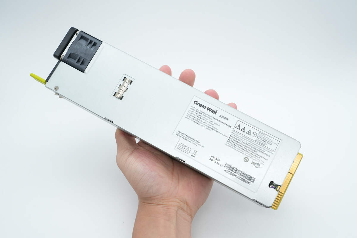
That's how big it is in the hand.
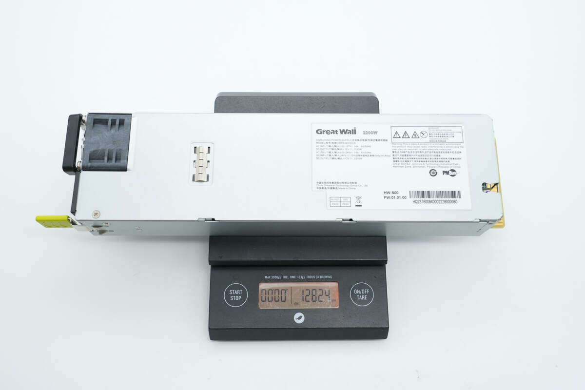
The weight is about 1282 g (45.22 oz).
Teardown
Next, let's take it apart to see its internal components and structure.
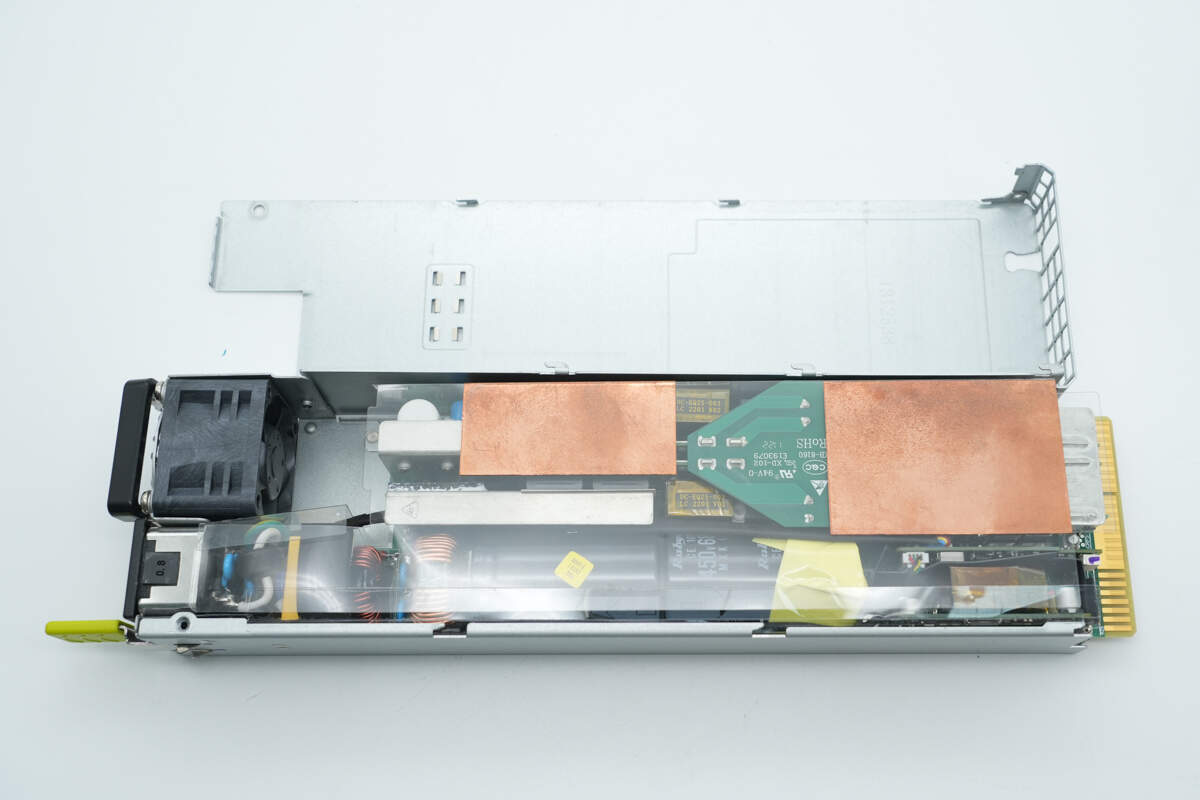
First, the screws are removed and the enclosure is opened. The PCBA module is covered with a Mylar sheet for insulation.
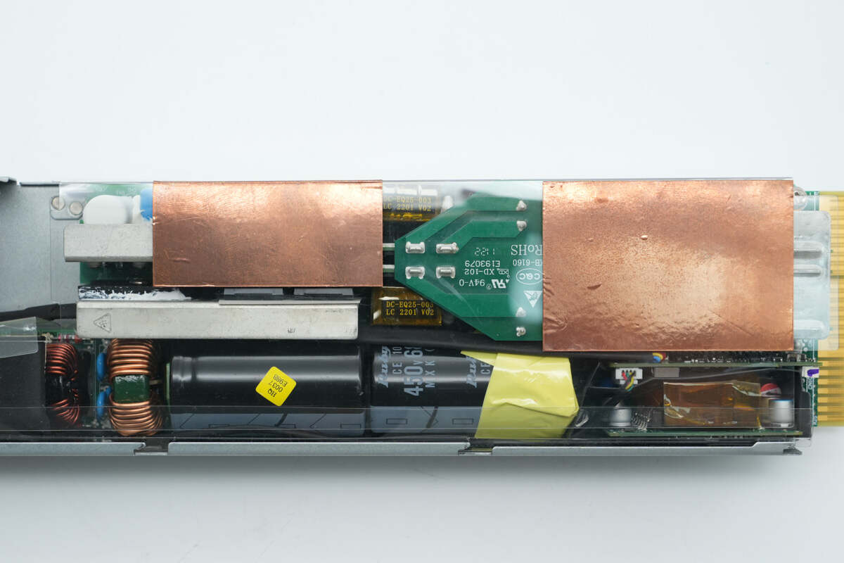
The inner side of the Mylar sheet is lined with copper foils for shielding.
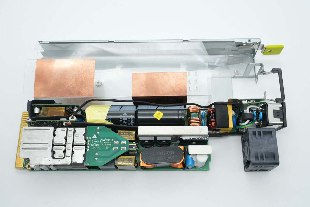
Remove the PCBA module.
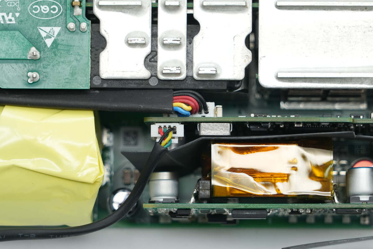
The indicator and cooling fan are connected via plug-in connectors.
The input wires are soldered directly to the PCBA module.
The length of the PCBA module is about 257 mm (10.12 inches).
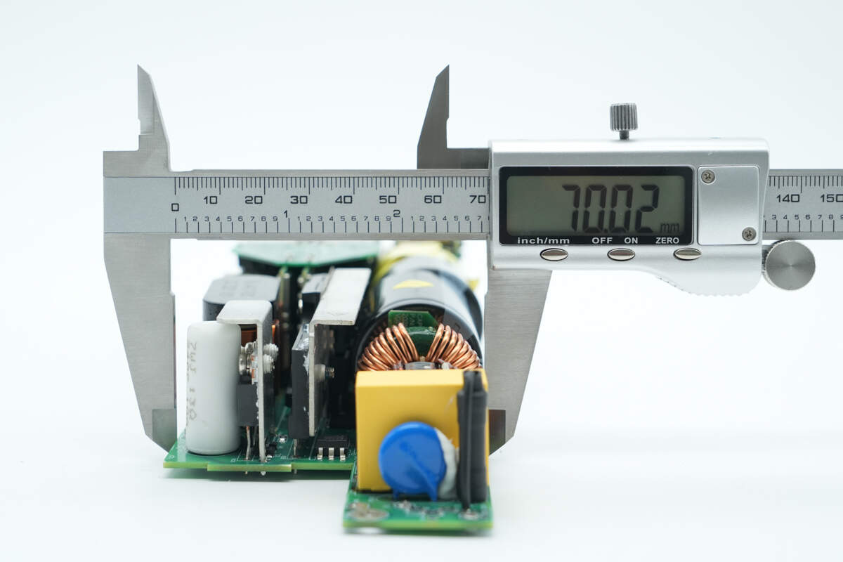
The width is about 70 mm (2.76 inches).
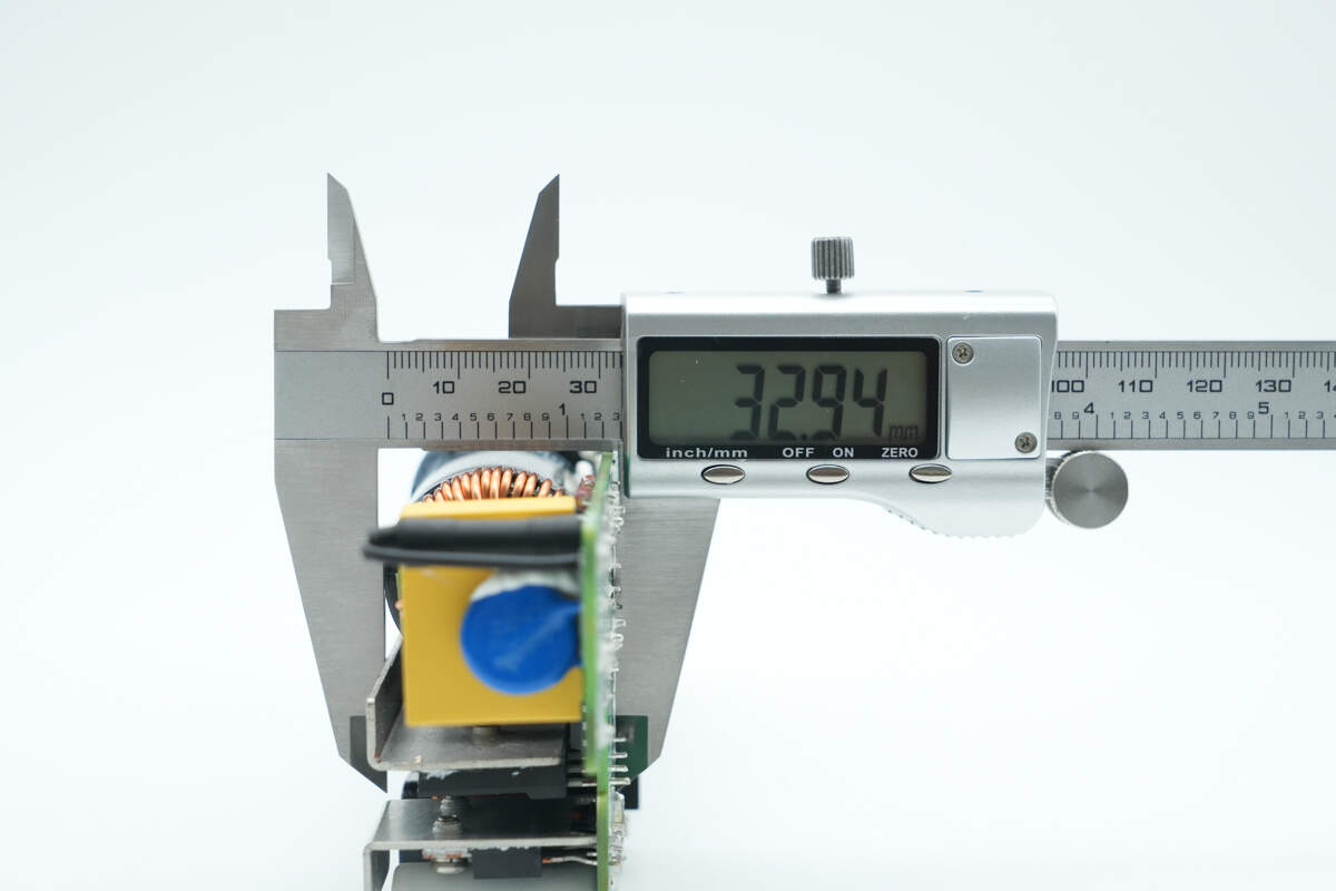
The thickness is about 32.9 mm (1.3 inches).
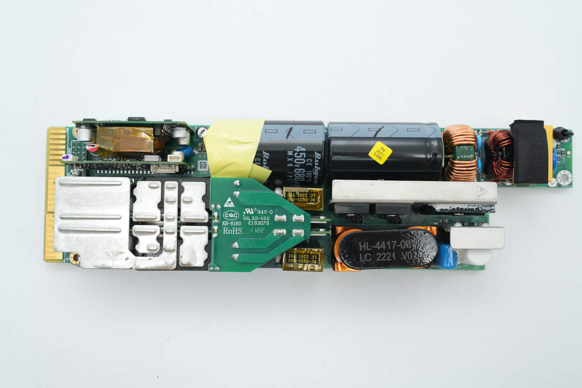
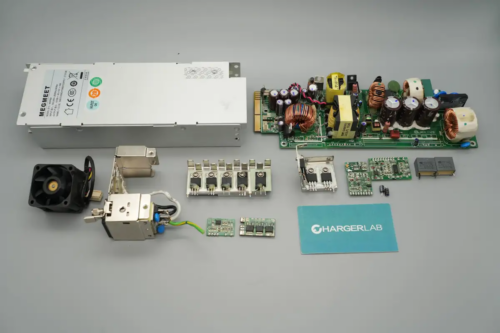
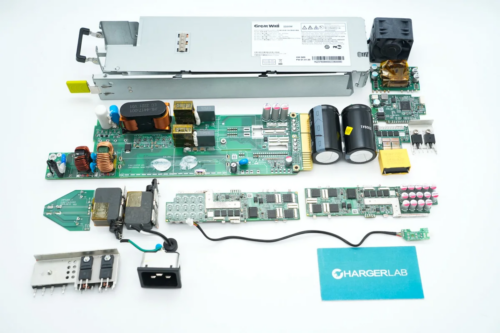
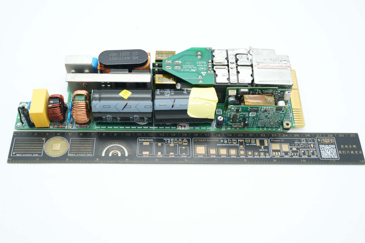
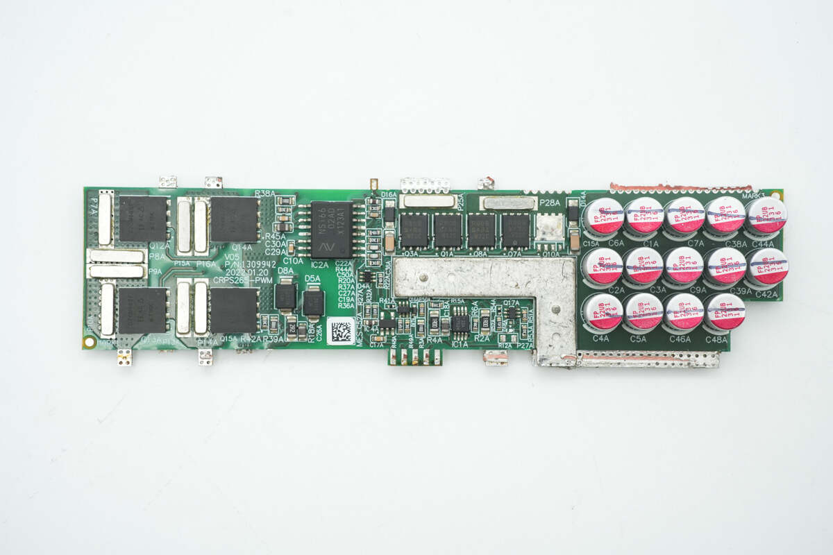
Overview of the front side of the PCBA module. On the right side is the AC input section, which includes a fuse, a safety X2 capacitor, common mode chokes, and capacitors. The upper left corner houses the auxiliary power supply and control PCB. The lower left corner contains the transformer module.
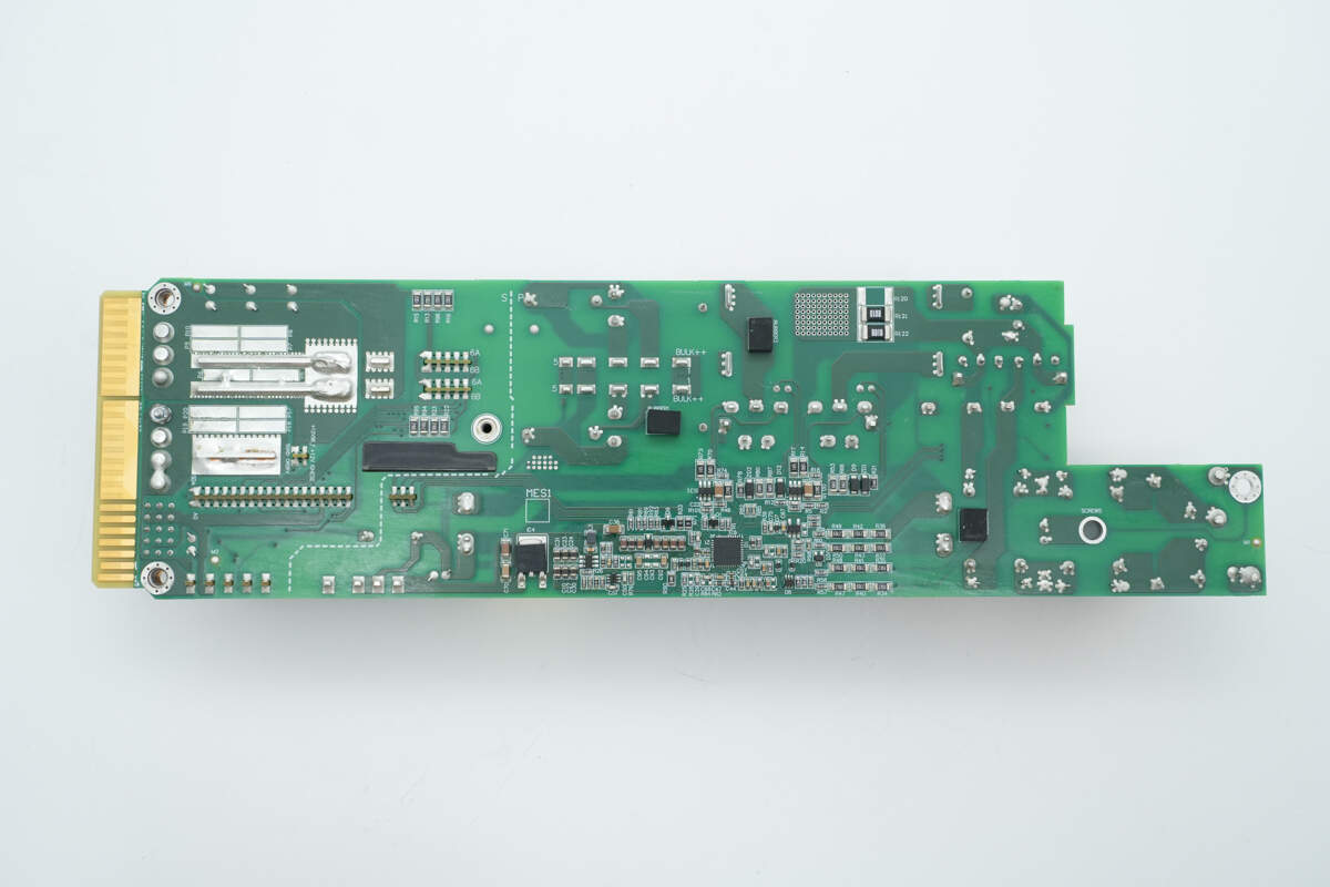
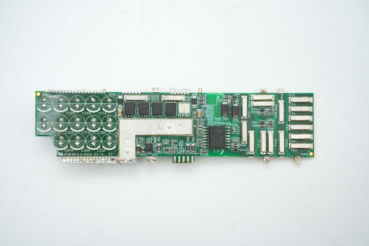
On the back side, there are the PFC controller, driver ICs, voltage regulation chip, and current sense resistors.
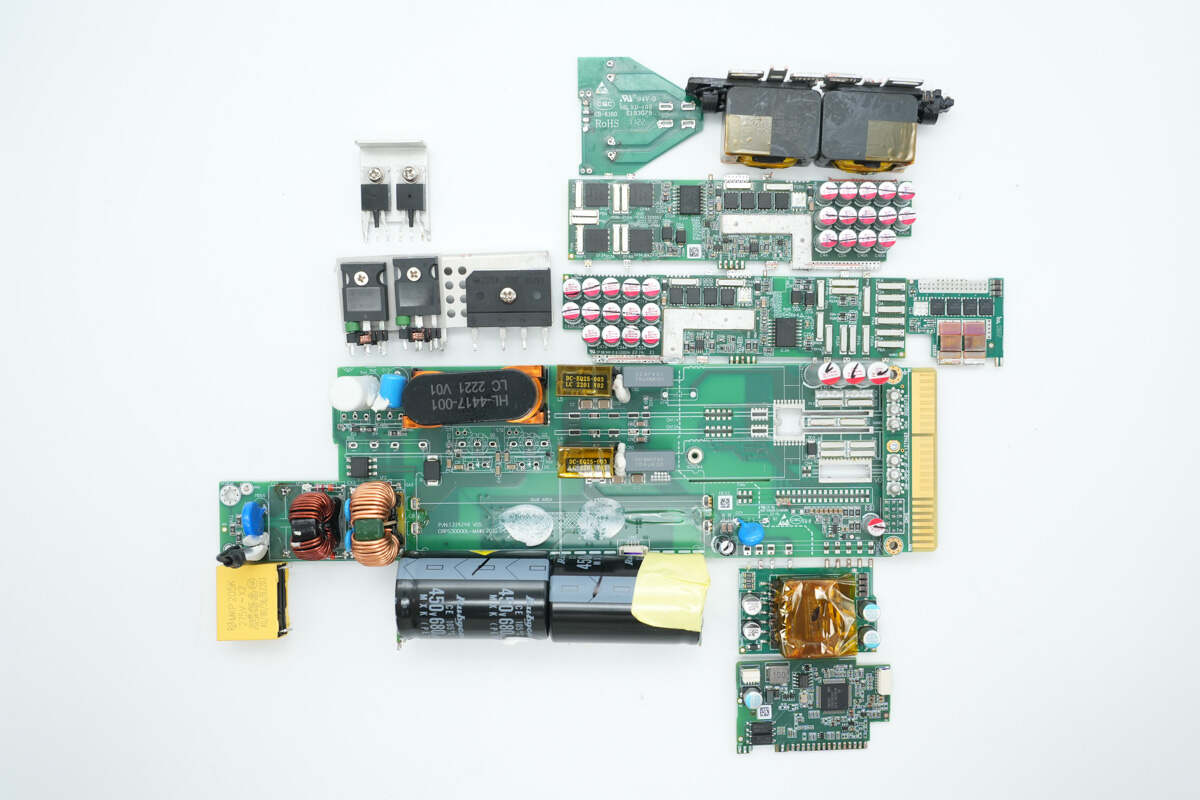
Disassemble the PCBA module.
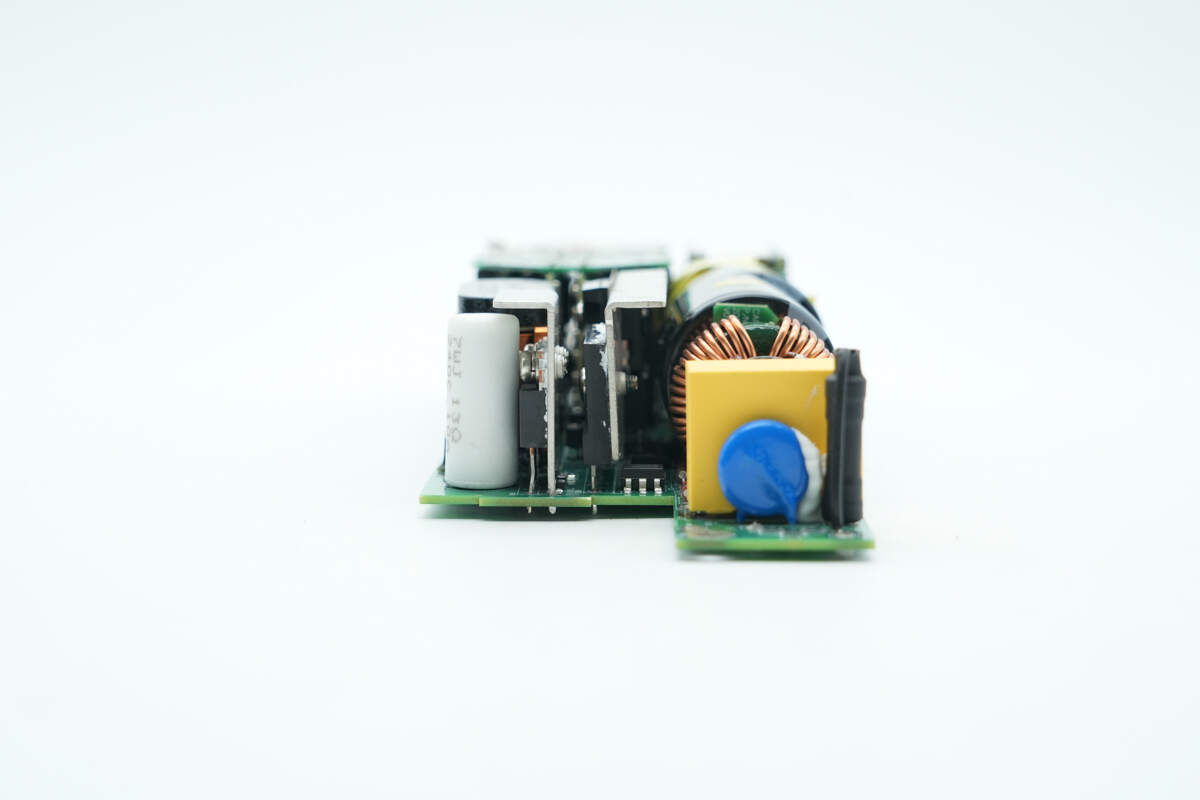
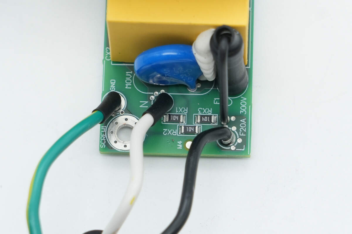
The input side is equipped with a fuse, varistor, safety X2 capacitor, and common mode chokes.
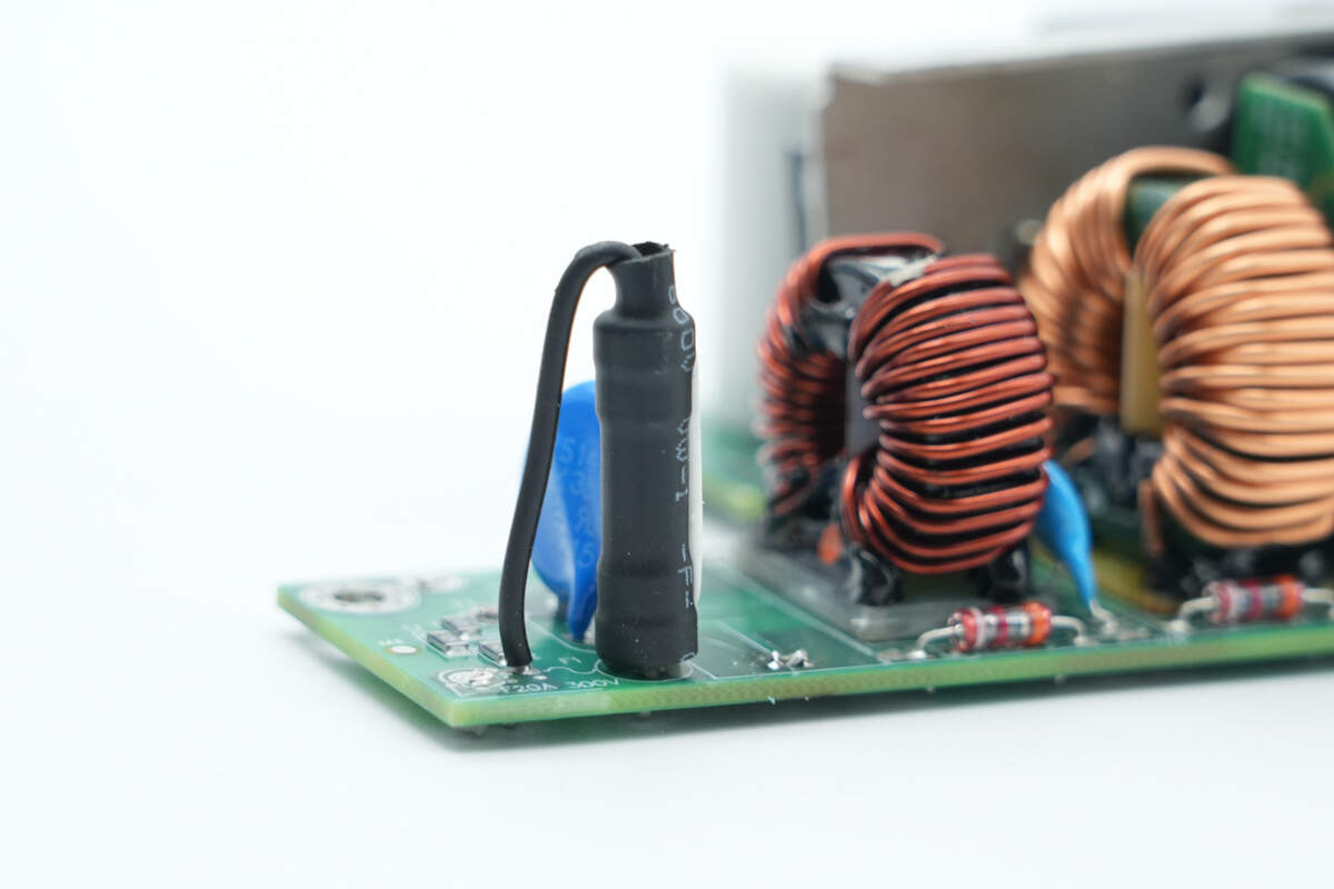
The fuse on the input side is insulated with heat shrink tubing.
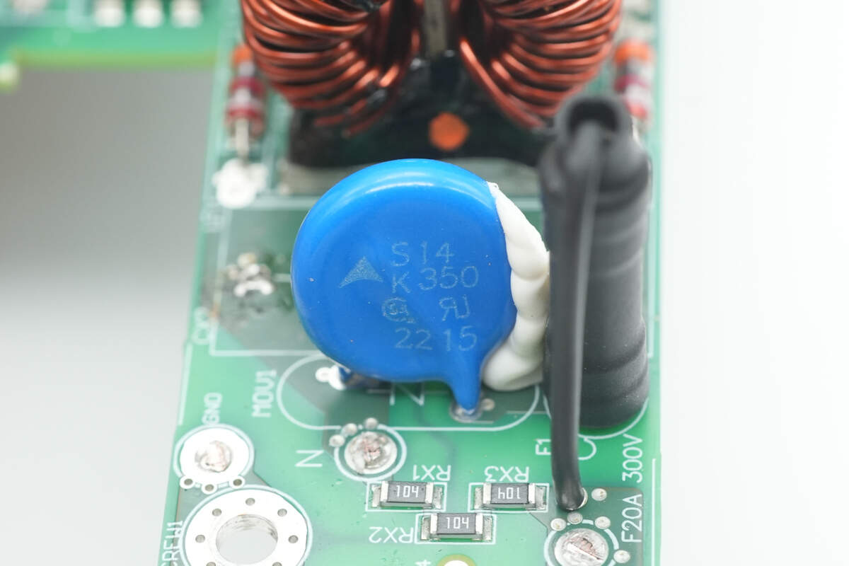
The varistor is manufactured by TDK, marked with S14 K350, and is used to absorb overvoltage surges.
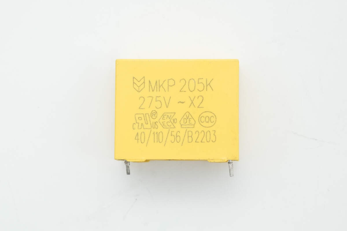
The safety X2 capacitor is rated at 2 μF.
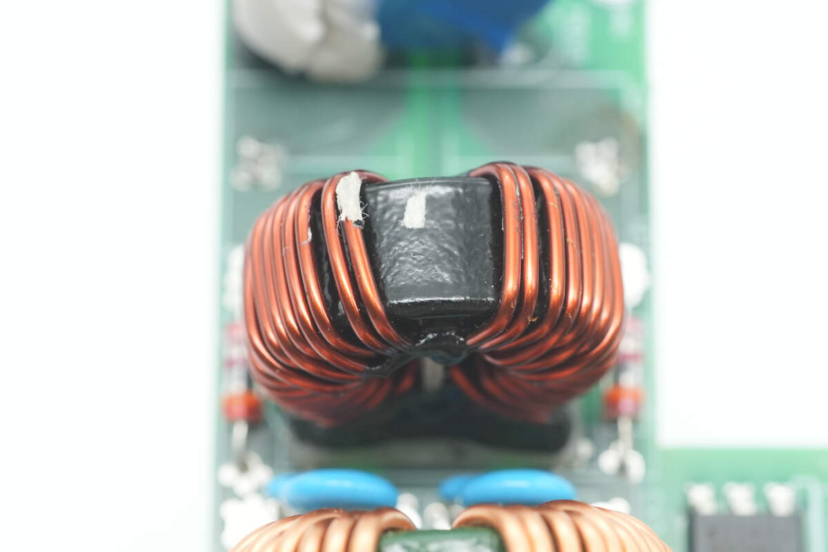
The common mode choke is wound with enameled wire and insulated at the bottom with a phenolic board.
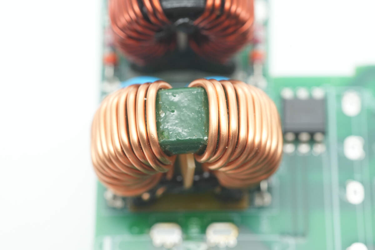
The other common mode choke features the same design.

Both common mode chokes have gas discharge tubes at the bottom, with blue Y capacitors positioned in between.
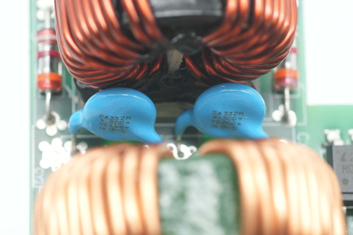
The two blue Y capacitors are from MURATA.
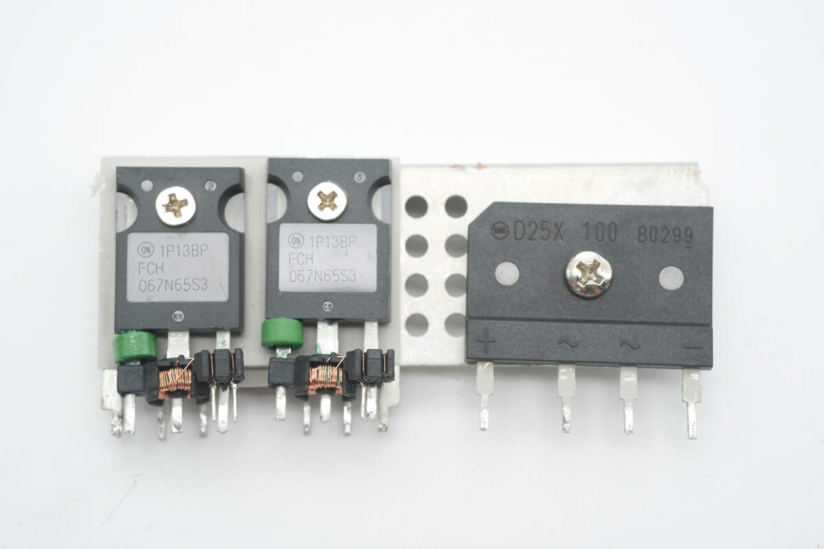
To the left of the heatsink are two PFC MOSFETs, and on the right side is the bridge rectifier.
On the back side, there are two PFC rectifiers.
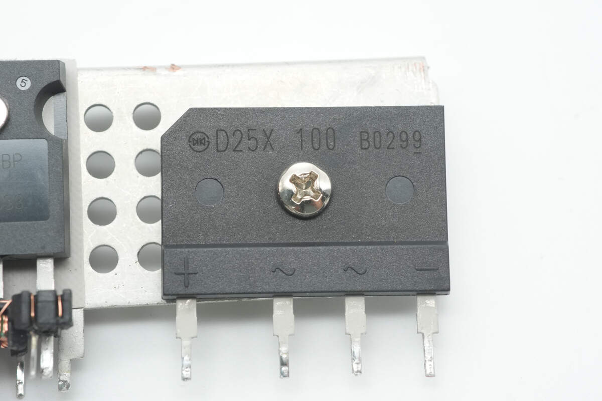
The bridge rectifier is from Shindengen, model D25XB100, rated at 1000V 25A, and uses a 5S package.
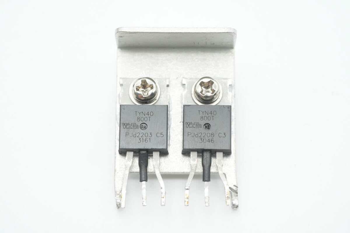
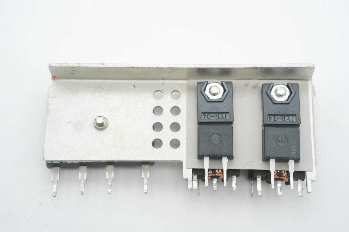
The two thyristors are from RePower, model TYN40-800T, rated at 800V 40A, and use a TO-220 package.
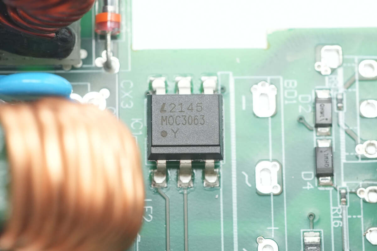
The LITEON MOC3063 optocoupler is used to control the conduction of the thyristors.

The startup resistor is rated at 13Ω.
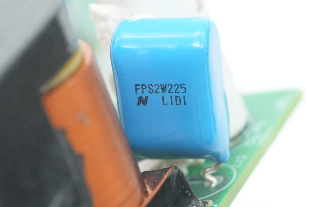
The film capacitor is from Nitsuko, part of the FPS series, rated at 450V and 2.2μF.
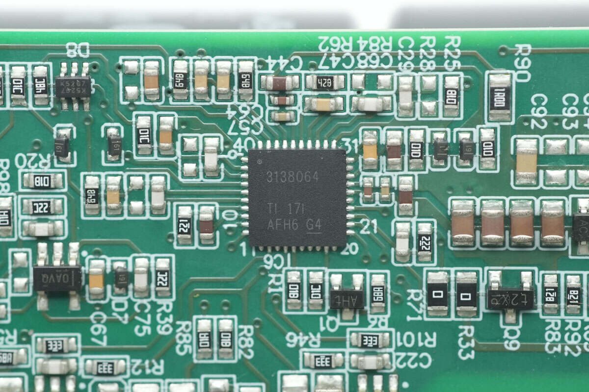
The PFC controller is from TI, model UCD3138064. It is a highly integrated digital power controller with 64kB embedded flash memory. It features SPI and I²C interfaces and supports phase-shift full-bridge, single-phase, and interleaved PFC, bridgeless PFC, hard-switch full-bridge and half-bridge, as well as half-bridge LLC and full-bridge LLC topologies. The device comes in a QFN40 package.
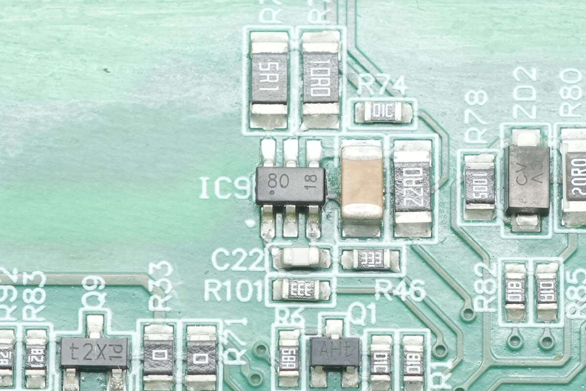
The driver marked with "80" is used to drive the PFC MOSFETs.
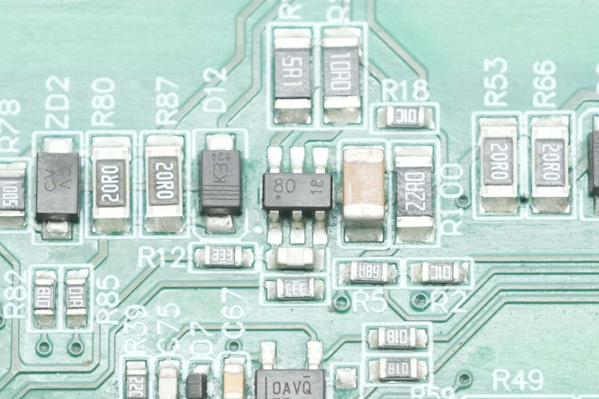
Two drivers are used in total to drive the interleaved PFC stage.
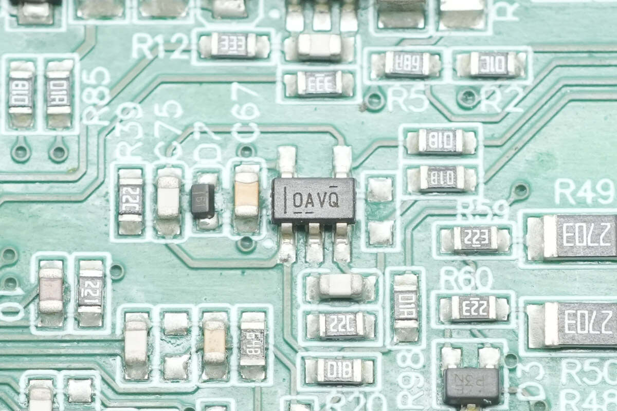
The operational amplifier is from TI, marked with OAVQ, model OPA365. It is a low-noise, single-supply, rail-to-rail operational amplifier in an SOT-23 package.
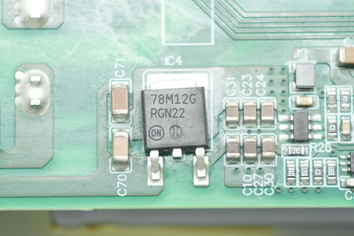
The voltage regulator is from Onsemi, model MC78M12. It supports an input voltage up to 35V, outputs 12V at 500mA, and comes in a DPAK-3 package.

The synchronous buck converter is from TI, marked with "200", model TPS562200. It has integrated MOSFETs, supports an input voltage up to 17V, delivers up to 2A output current, and comes in an SOT-23 package.

Close-up of the voltage divider resistors used for voltage sensing.
The PFC boost inductor is wound with flat copper wire.
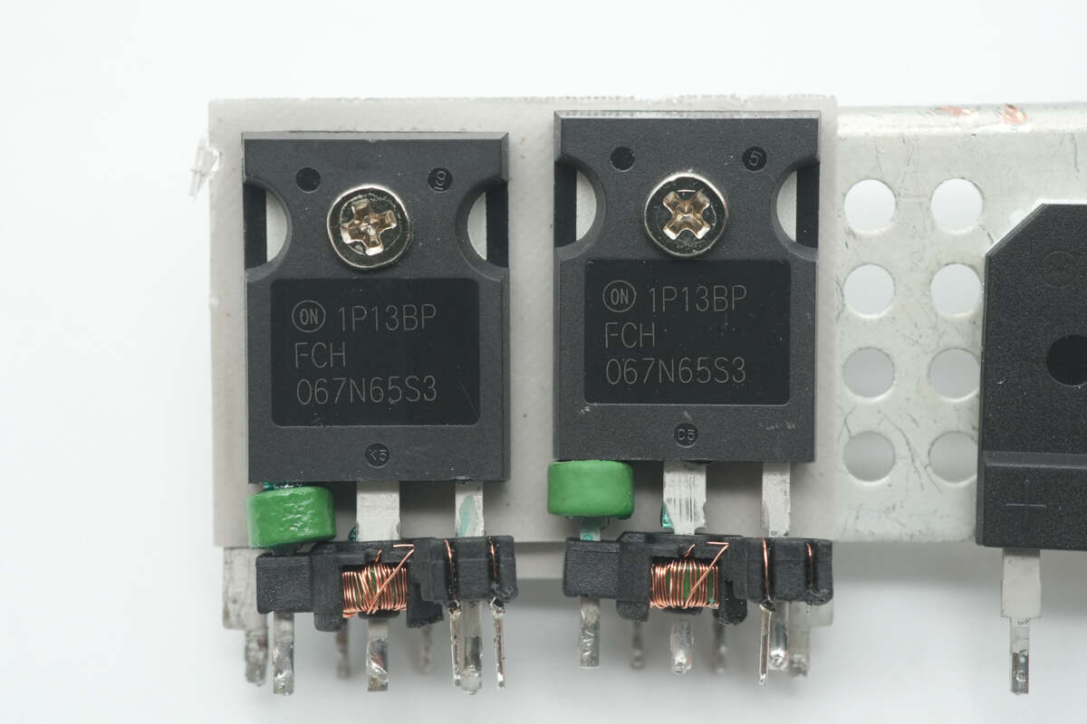
The PFC MOSFETs are from Onsemi, model FCH067N65S3. These are N-channel MOSFETs rated for 650V with an Rds(on) of 67mΩ, and come in a TO-247 package. A current transformer, formed with a magnetic ring, is connected to the drain for current sensing.
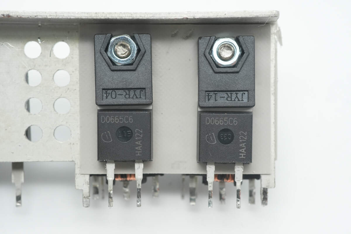
The component marked with D0665C6 is from Infineon, model IDH06G65C6. It is a SiC diode rated at 650V and 6A, and comes in a TO-220-2 package.
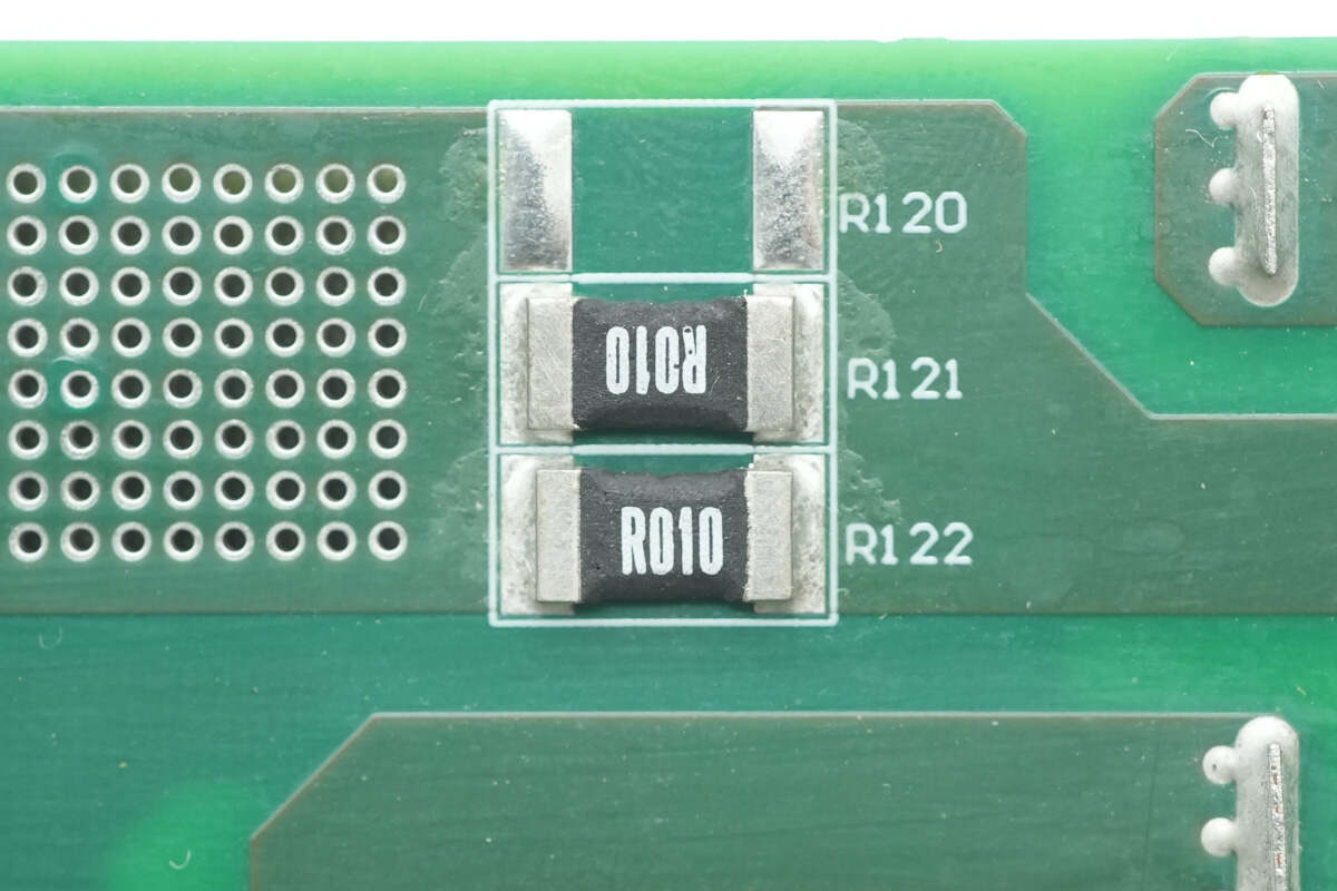
Two 10mΩ resistors are connected in parallel for current sensing in the PFC stage.
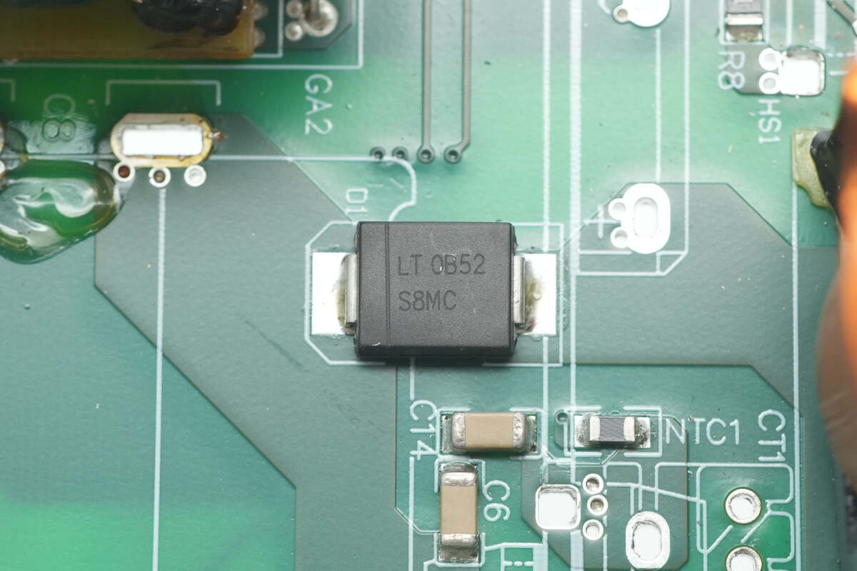
The PFC bypass diode is from LITEON, model S8MC. It is rated at 1000V and 8A, and comes in an SMC package.
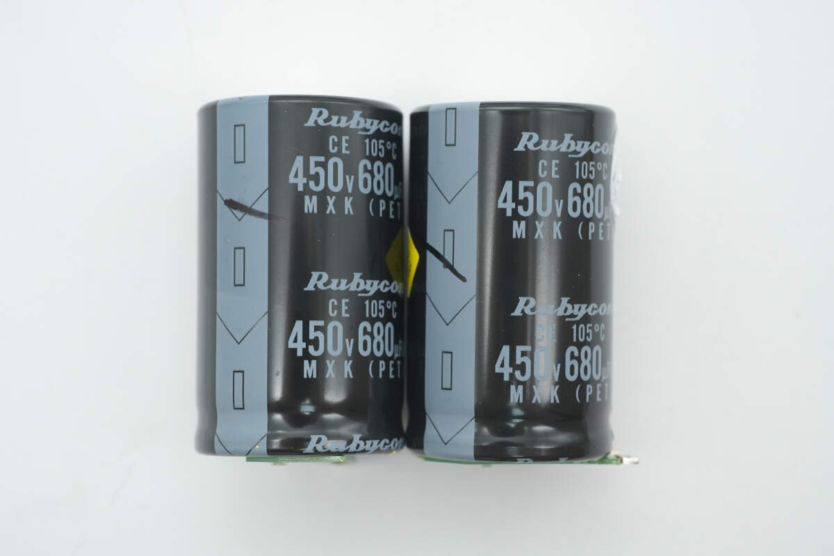
The two high-voltage filter capacitors are from Rubycon, part of the MXK ultra-compact electrolytic series. Each is rated at 450V, 680μF.
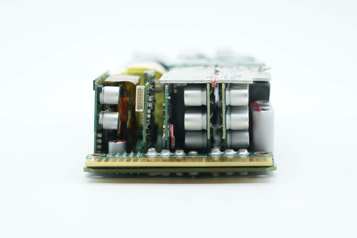
At the output side, there are multiple PCBs: an auxiliary power supply PCB, a control PCB, an output control PCB, and a transformer PCB. On the right side, there are filter capacitors.
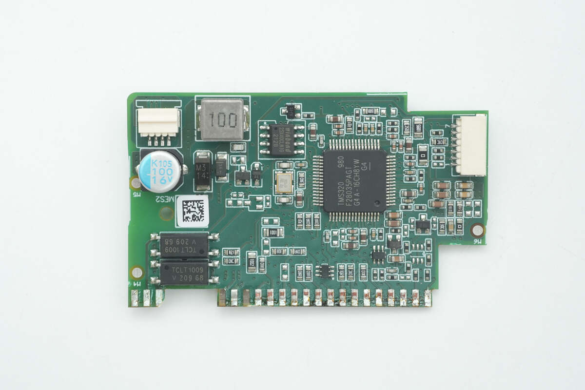
The front side of the control PCB features the LLC controller, memory chip, filter inductor, capacitor, and feedback optocouplers.
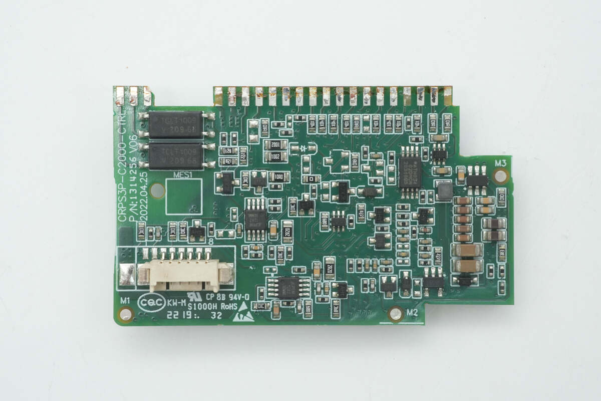
The back side has memory chips, operational amplifiers, and feedback optocouplers.
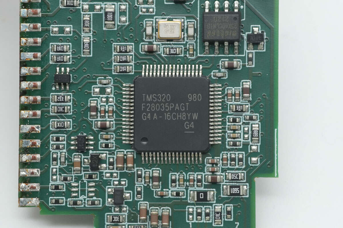
The LLC controller is from Texas Instruments, part of the C2000 real-time microcontroller series, model TMS320F28035PAG. It features a 32-bit CPU core running at 60MHz, supports coordinated computations, fast interrupt response and handling, and includes 128KB of flash memory. This MCU is commonly used in applications such as air conditioner outdoor units, DC-DC converters, inverters and motor control, OBC, charging stations, and BLDC motor drives. It comes in a TQFP64 package.
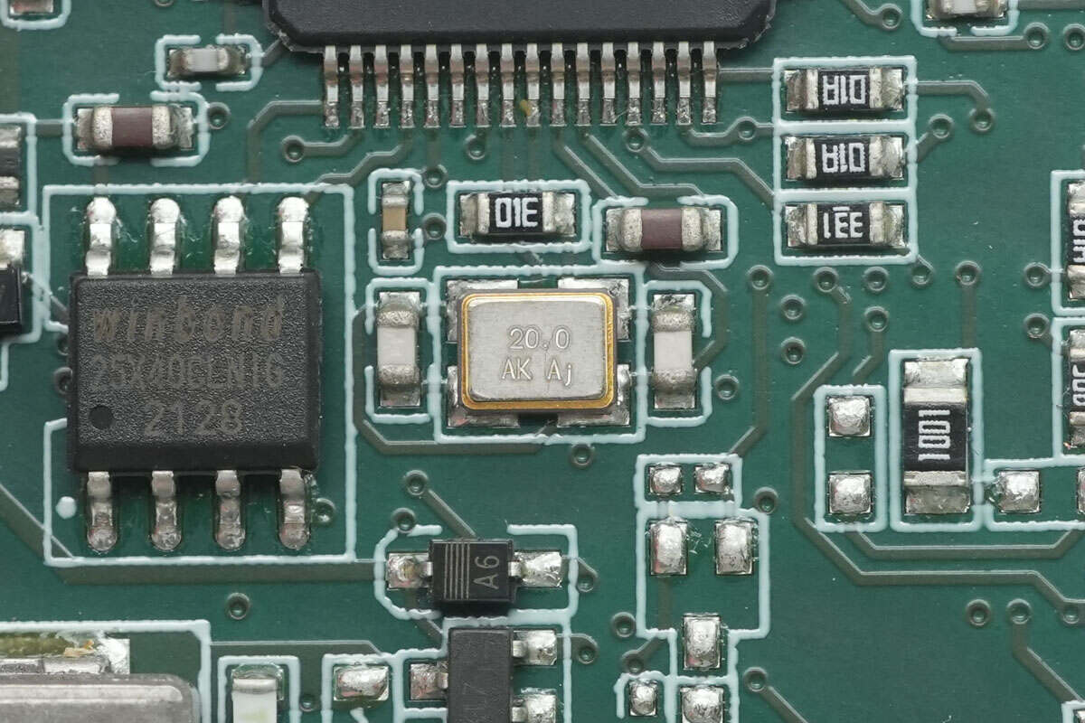
Close-up of the 20.0MHz clock crystal oscillator.
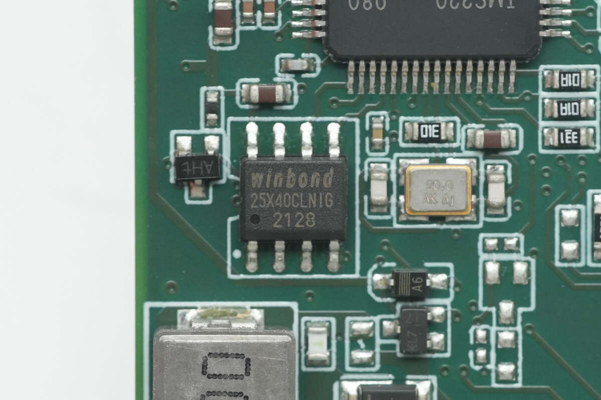
The memory chip is from Winbond, model W25X40CLSNIG, with a capacity of 512KB, and comes in an SOIC-8 package.

The other memory chip is from Microchip, marked with "02D", model AT24C02D. It has a capacity of 256 bytes and comes in a TSSOP-8 package.
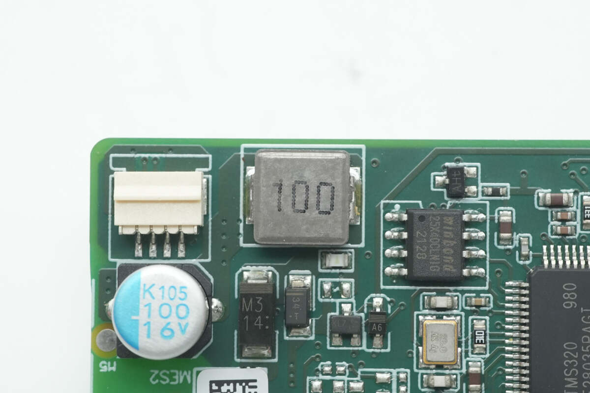
Close-up of the 10μH alloy inductor.
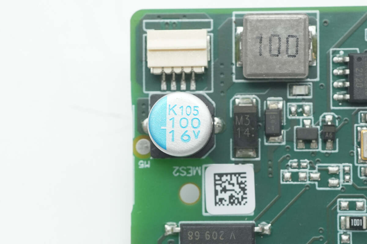
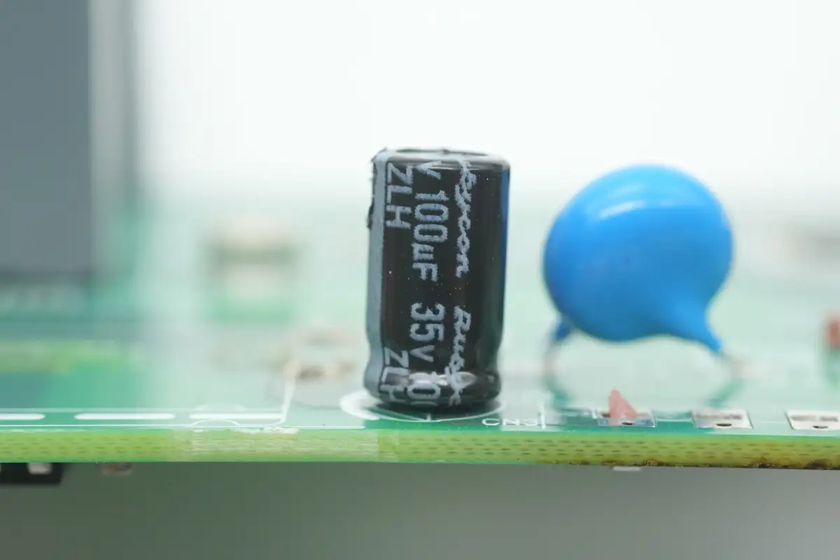
The filter capacitor is rated at 100μF, 16V.
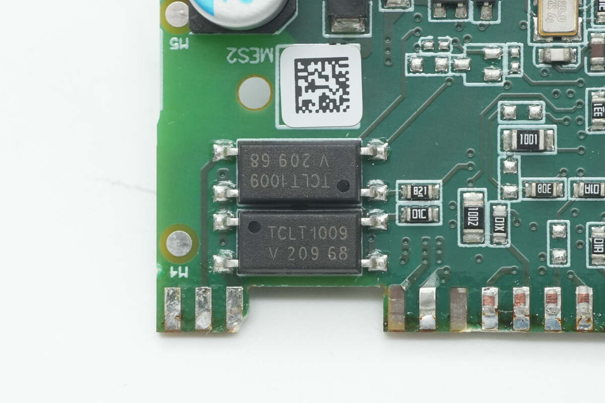
The isolation optocoupler is from VISHAY, model TCLT1019.
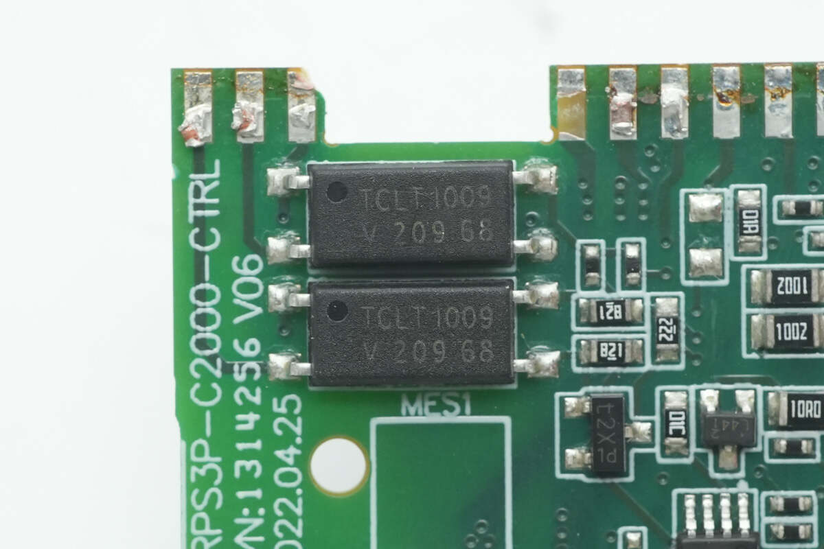
There are two optocouplers of the same model on the back side.
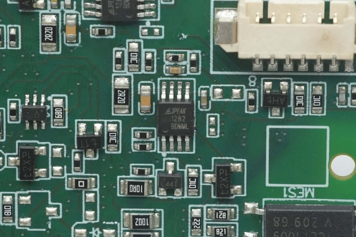
The operational amplifier is from 3PEAK, marked with 1282, model TP1282. It features rail-to-rail input and output and comes in an MSOP-8 package.

The other operational amplifier has the same model.
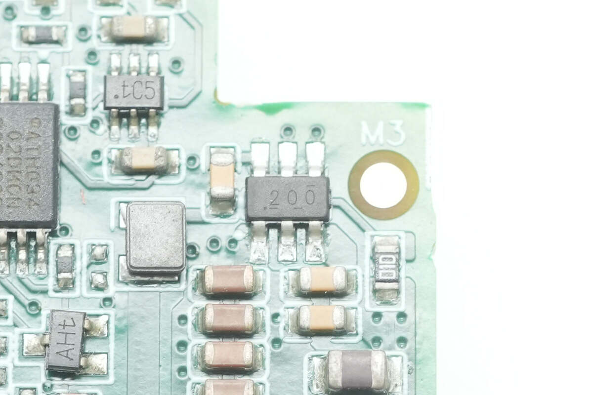
The synchronous buck converter chip is a TI TPS562200.
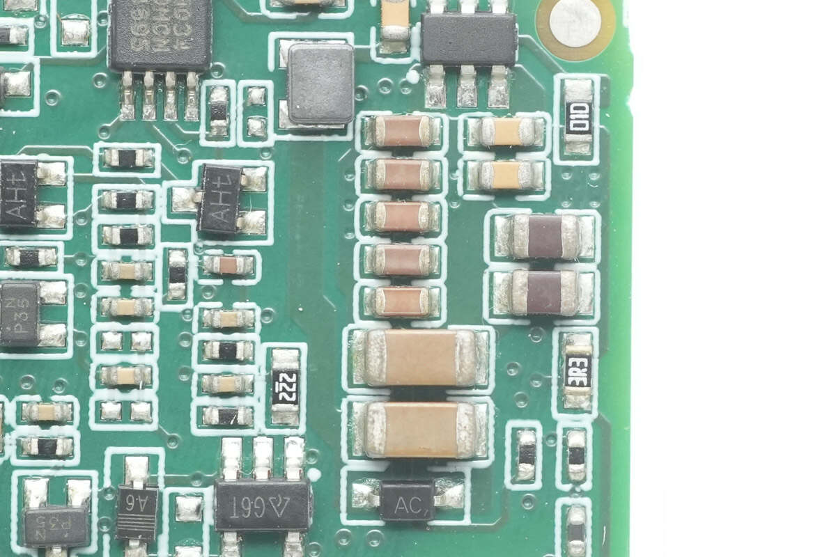
Close-up of the filtering MLCC capacitors.
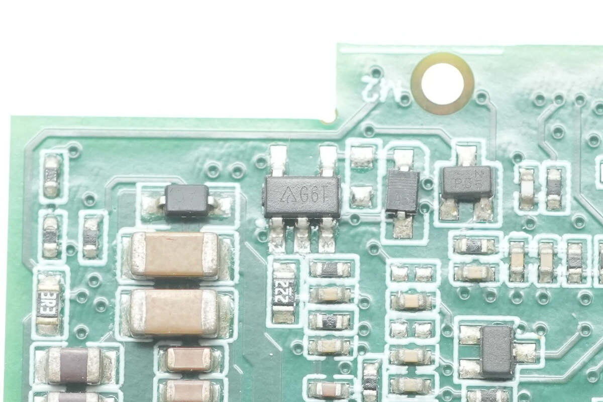
The single operational amplifier is from DIODES, marked with G6T, model AS321. It is a low-power single op-amp in an SOT-25 package.
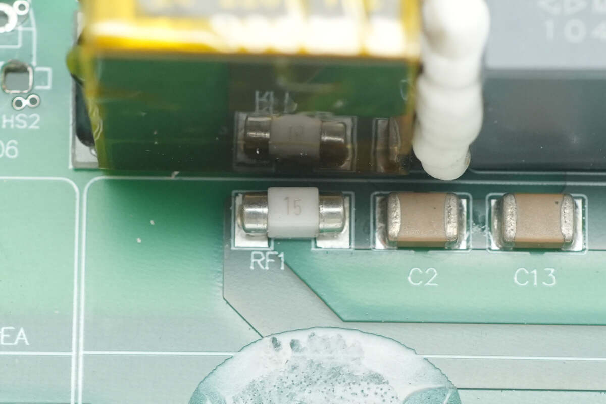
A 15A fuse is used for overcurrent protection in the LLC stage.
On the left side of the transformer PCB, there are full-bridge LLC MOSFETs, an isolation driver, synchronous rectifiers, and solid capacitors.
On the other side, there are isolation drivers and synchronous rectifiers. The two transformer PCBs are symmetrically designed with identical components. One PCB will be described to save space.
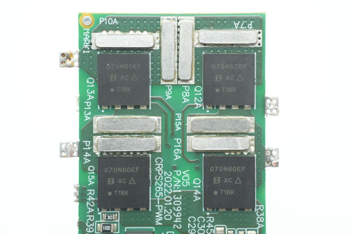
The full-bridge LLC MOSFETs are from VISHAY, model SiHH070N60EF. They are rated for 650V, have an Rds(on) of 75mΩ, and come in a PowerPAK 8x8 package.

The isolation driver is from NOVOSENSE, model NSi6602AD. It features an isolated dual-channel gate driver with 5.7kV RMS isolation capability, 4A sourcing current, and 6A sinking current, housed in an SOW16 package.
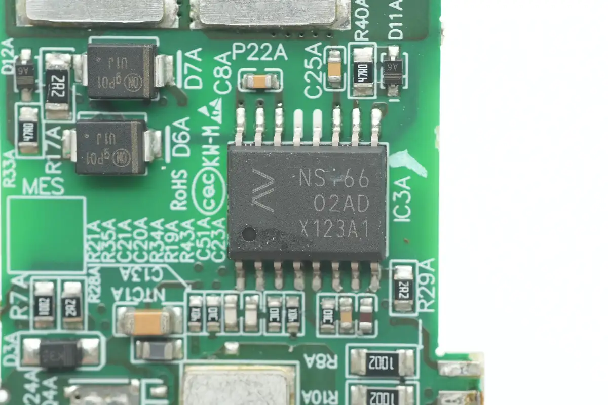
The other isolation driver has the same model.
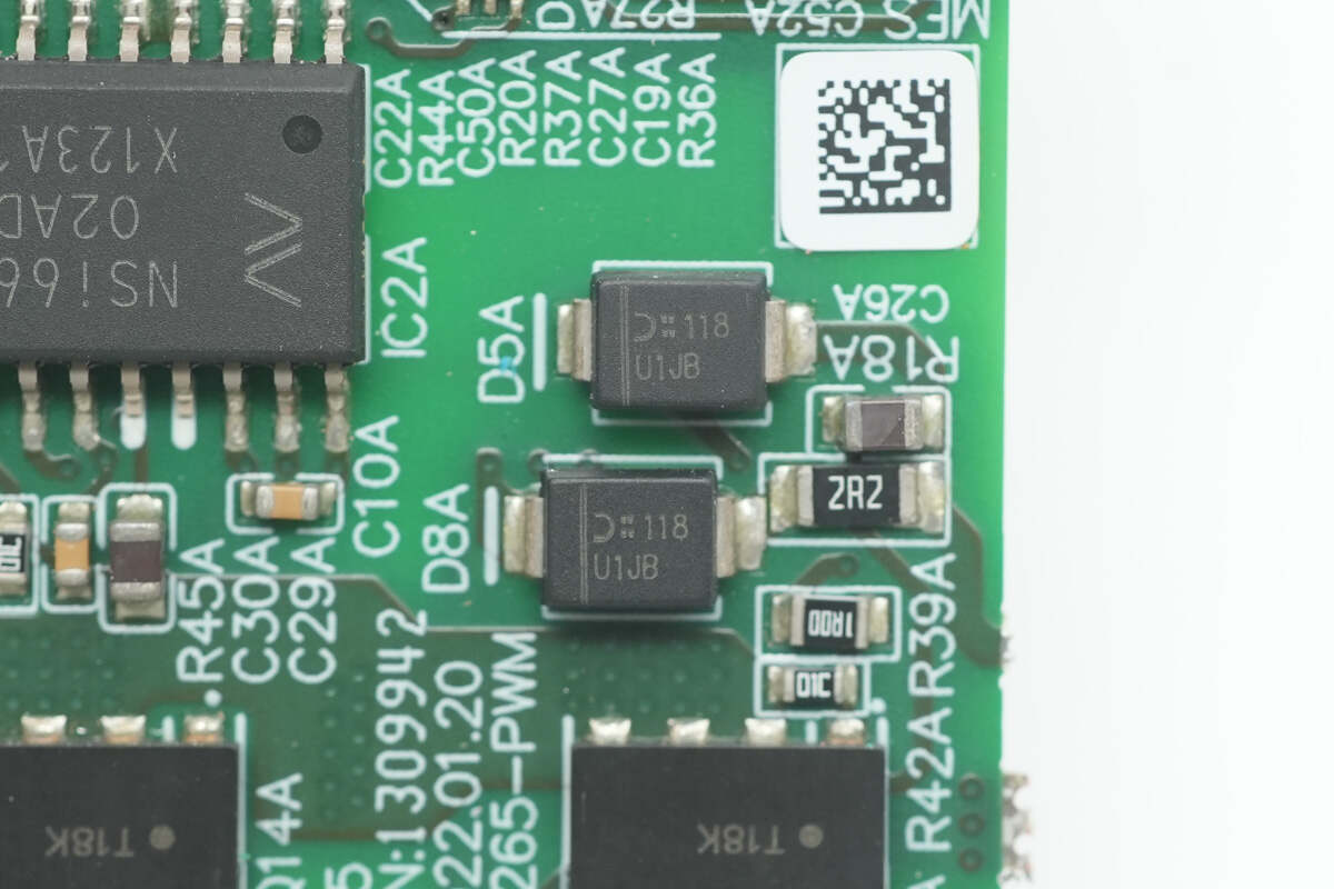
The two fast recovery diodes are from DIODES, marked with U1JB, model MURS160. They are ultra-fast recovery diodes rated at 600V, 1A, and come in an SMB package.
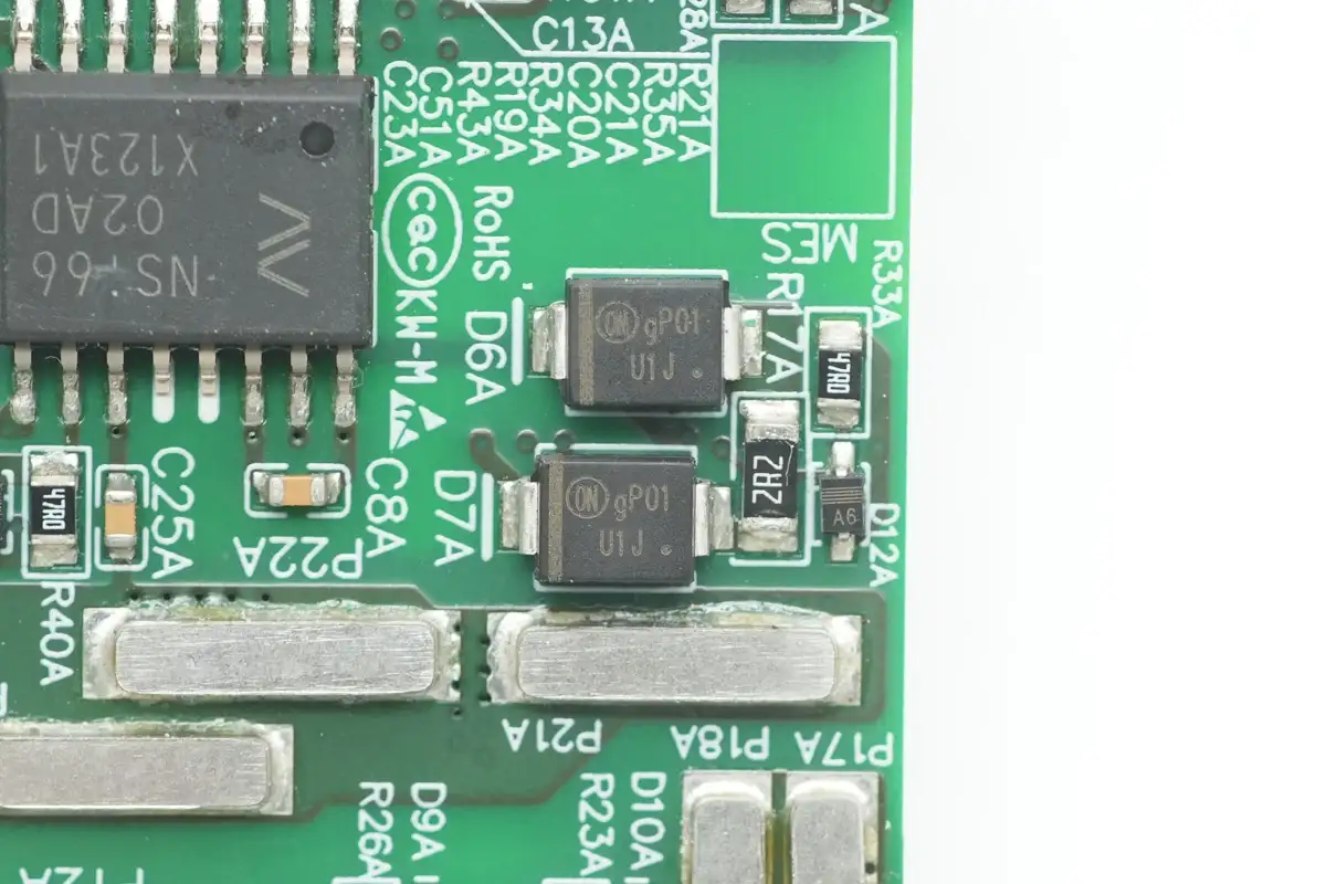
On the other side, two fast recovery diodes are from Onsemi, marked with U1J, model MURS160. They are ultra-fast recovery diodes rated at 600V, 1A, and come in an SMB package.

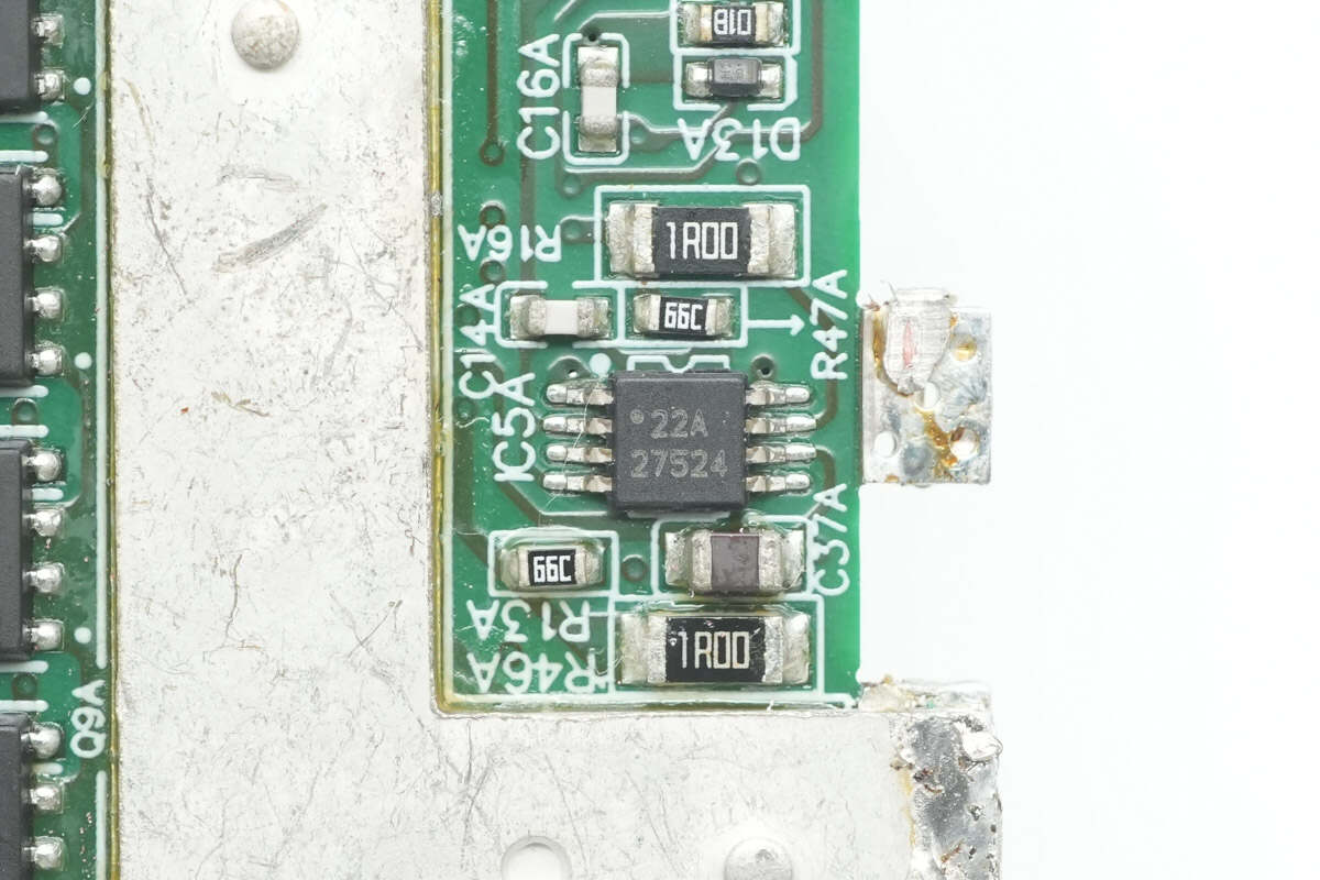
The driver for the synchronous rectifiers is from TI, model UCC27524. It is a dual-channel, 5V high-speed low-side gate driver with negative input voltage capability, housed in an HVSSOP-8 package.
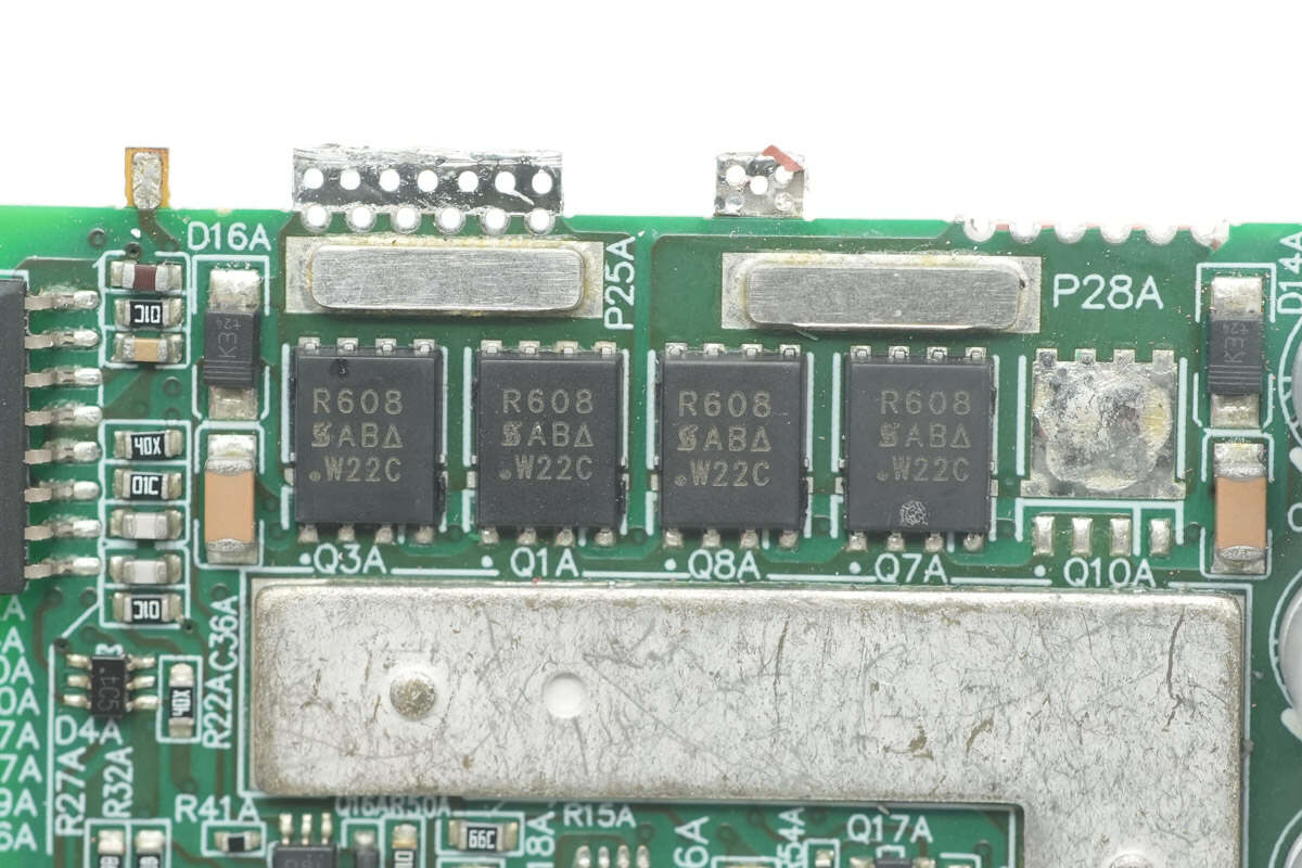
The synchronous rectifiers are from VISHAY, model SiR608DP. They are N-channel MOSFETs rated for 45V, with an Rds(on) of 1.2mΩ, and come in a PowerPAK SO-8 Single package.
The other side also features a TI UCC27524 driver.
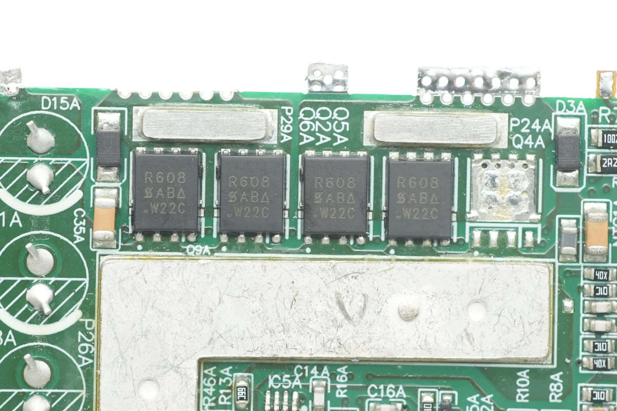
The synchronous rectifiers use VISHAY SiR608DP, with a thermistor located on the right side.

Close-up of the chip marked with "5A2RV."
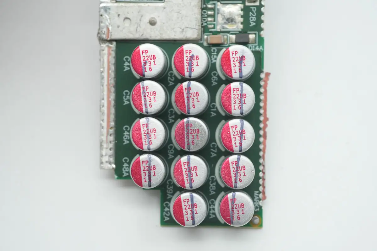
The filter capacitors are from Nichicon. They are conductive polymer aluminum solid electrolytic capacitors, rated at 330μF, 16V.

The resonant inductor is wrapped with high-temperature insulating tape.
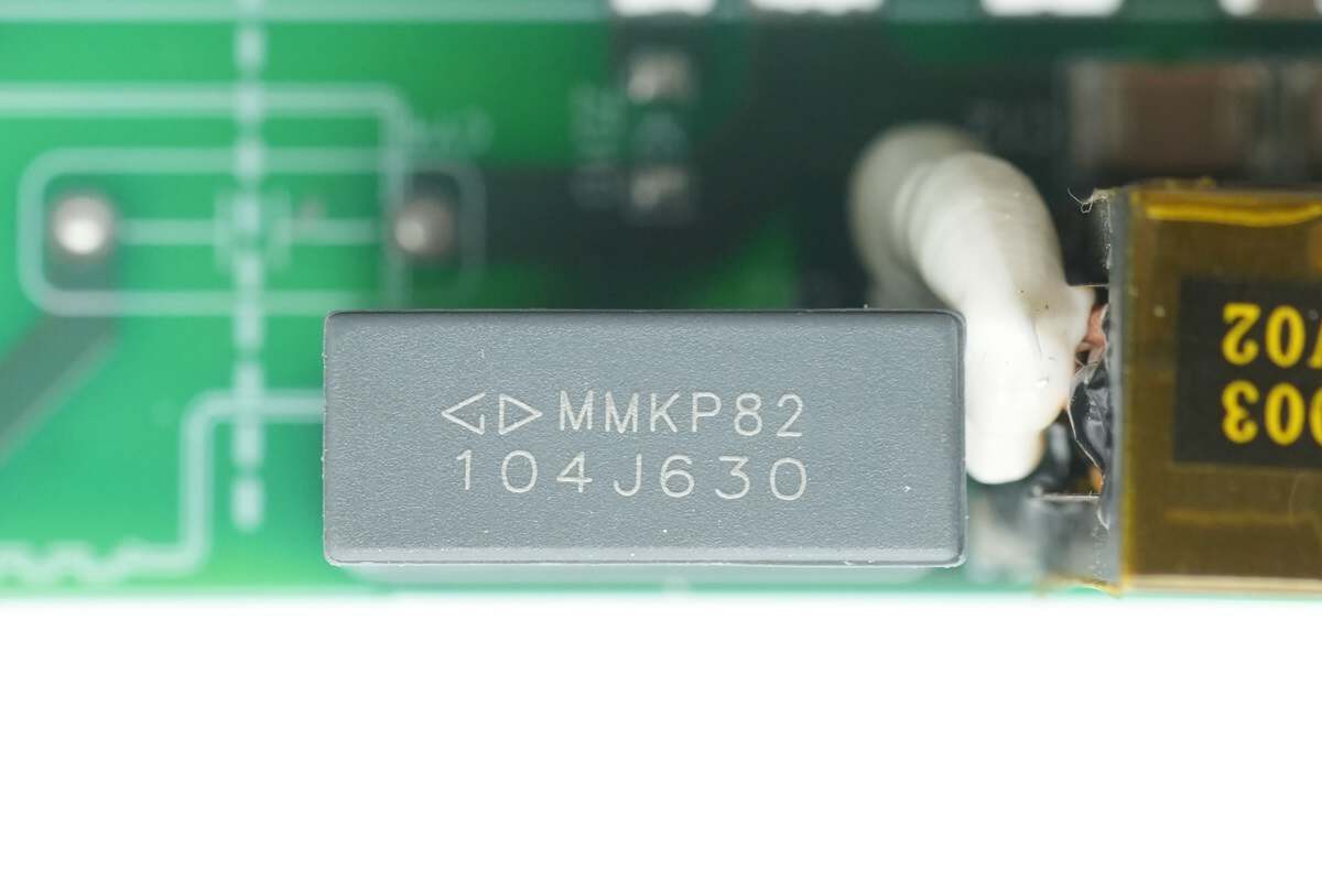
The resonant capacitor is from Faratronic, rated at 0.1μF, 630V.
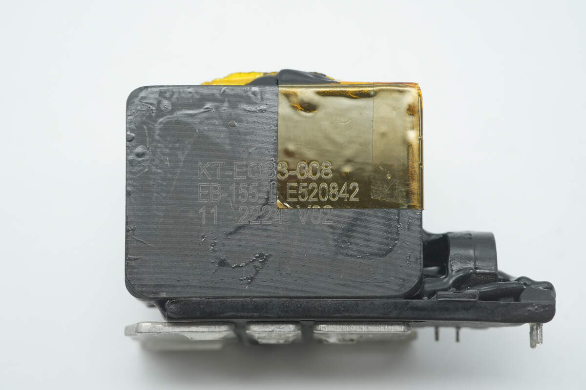
The transformer core is insulated with a plastic plate, and a current transformer is installed on the primary side.
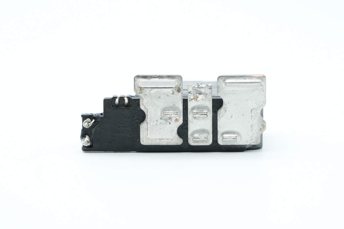
The transformer secondary windings are connected via soldered copper strips.

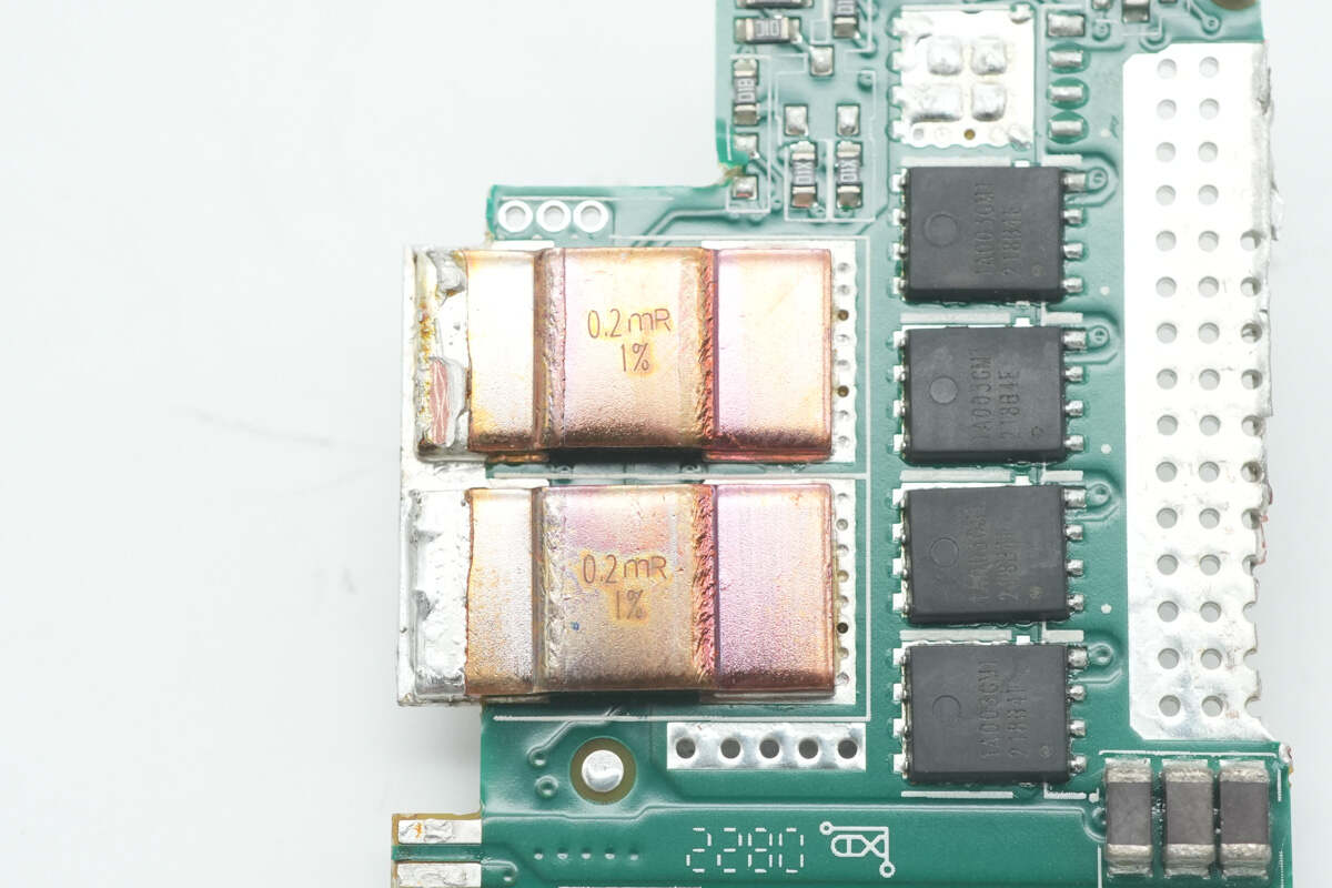
The output control PCB is equipped with current sense resistors and VBUS MOSFETs.
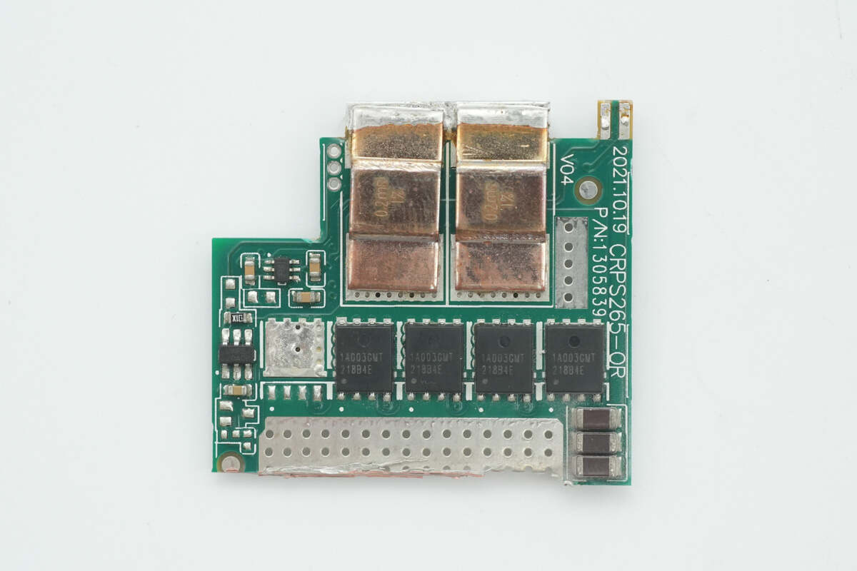
The other side also has current sense resistors and VBUS MOSFETs, along with a current sensing IC and an ideal diode controller.
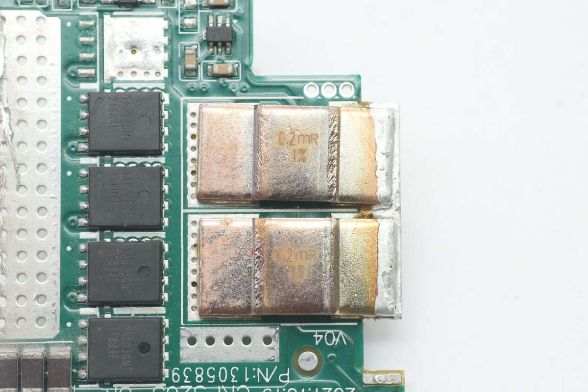
The value of the current sense resistors is 0.2mΩ.
There are also two 0.2mΩ current sense resistors on the back side.
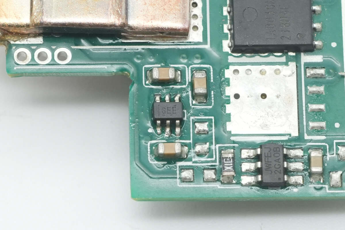
The current sensing chip is from TI, marked with "SEE," model INA211. It is a bidirectional high-precision current sense amplifier, housed in an SC70 package.
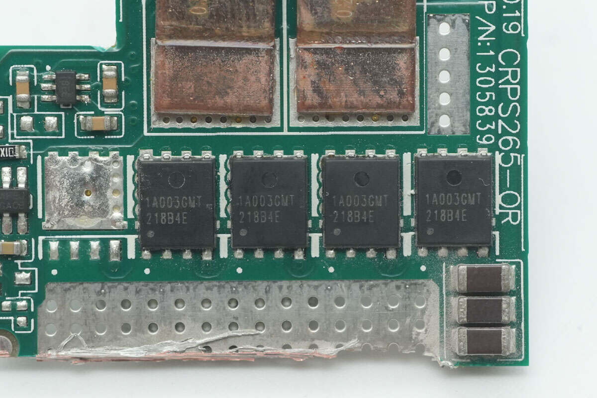
The output VBUS MOSFETs are from APEC, model AP1A003GMT. These are N-channel MOSFETs rated for 30V, with an Rds(on) of 0.99mΩ, and come in a PMP5x6 package.
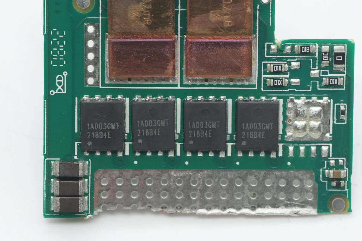
On the other side, there are four VBUS MOSFETs of the same model.
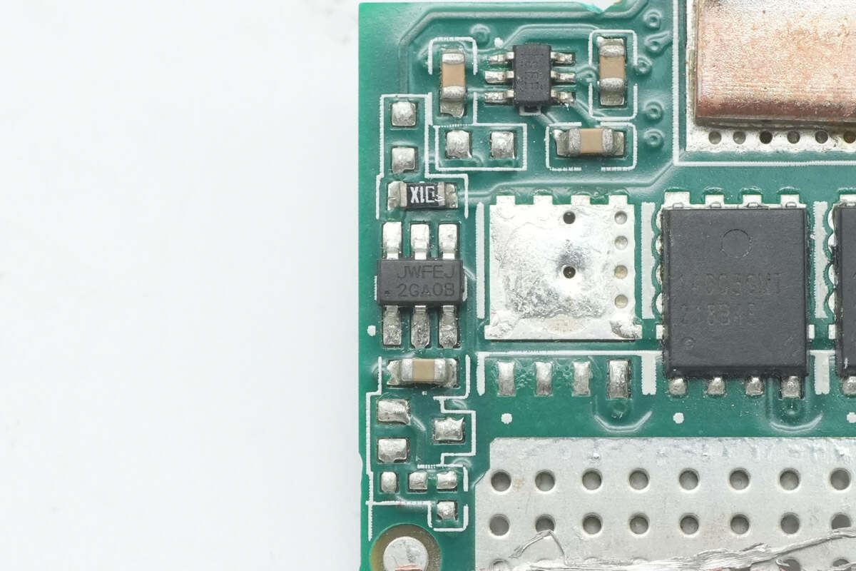
The ideal diode controller is from JOULWATT, marked with JWFE, model JW7260. It reduces power loss by replacing traditional Schottky diodes with NMOS transistors. It supports an operating voltage range of 6–80V and has zero reverse DC current. The chip features an enable control pin and delivers a 1A peak shutdown drive current. It comes in a TSOT-23-6 package.

Here is the information about JOULWATT JW7260.

The three output filter capacitors are all rated at 1000μF, 16V.
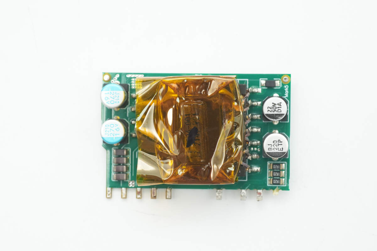
The auxiliary power supply PCB is equipped with filter capacitors and a transformer.

The back side features a switching power supply chip, a feedback optocoupler, and a rectifier.
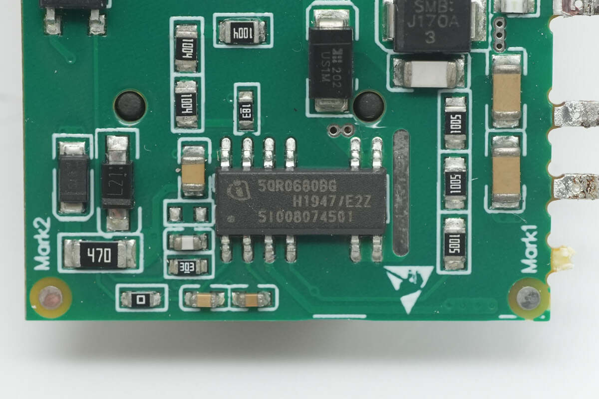
The auxiliary power supply chip is from Infineon, model ICE5QR0680BG. It integrates an 800V MOSFET internally, supports 42W output power over a wide voltage range, and features comprehensive protection mechanisms. It comes in a DSO-12 package.
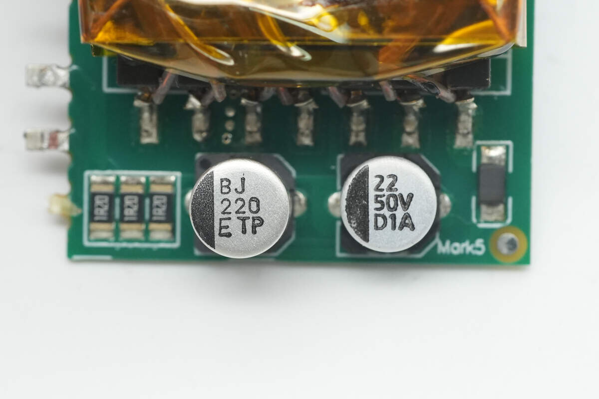
The two filter capacitors are rated at 220μF 25V and 22μF 50V, respectively.

The transformer core is tightly wrapped with high-temperature insulating tape.

The VISHAY TCLT1009 optocoupler is used for output voltage feedback.
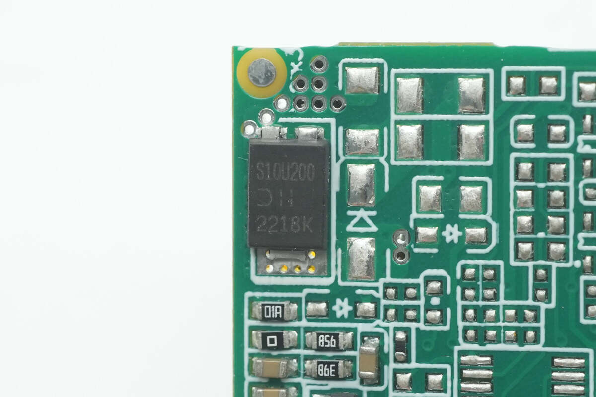
The rectifier diode is from DIODES, model SBR10U200P5. It is a Schottky Barrier Rectifier rated at 200V, 10A, and comes in a PowerDI5 package.
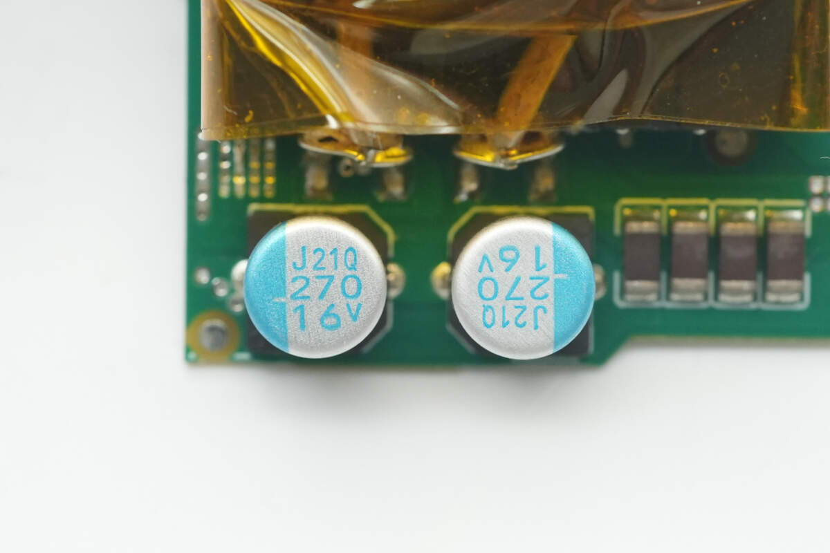
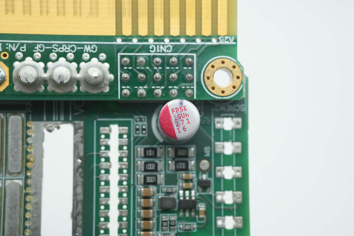
The two filter capacitors are from NCC, part of the PXJ series of ultra-low ESR conductive polymer solid aluminum electrolytic capacitors, rated at 270μF, 16V.
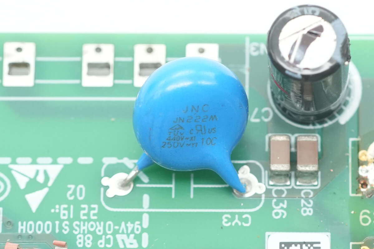
The blue Y capacitor is from JYA-NAY.
The filter capacitor is from Rubycon, rated at 100μF, 35V.
The filter capacitor is rated at 270μF, 16V.
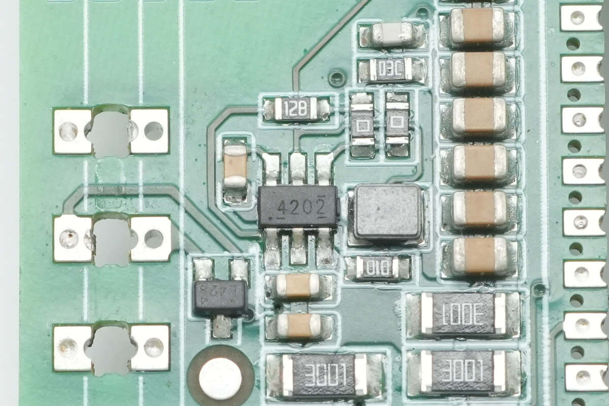
The synchronous buck chip is from Texas Instruments, marked with "4202", model TPS54202. It is a synchronous step-down converter with a 4.5–28V input voltage range and a 2A output current. The chip has integrated power MOSFETs and comes in an SOT-23 package.
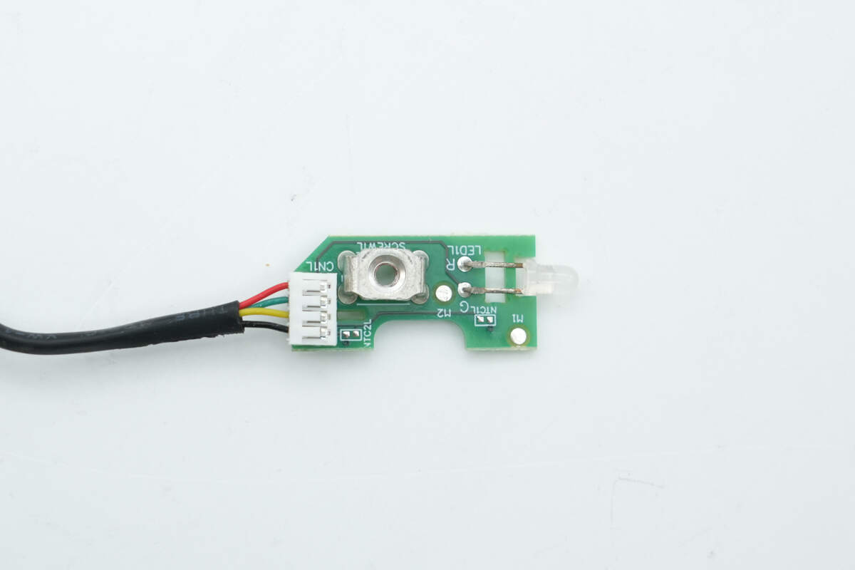
The indicator PCB has reserved a solder pad for the NTC thermistor.
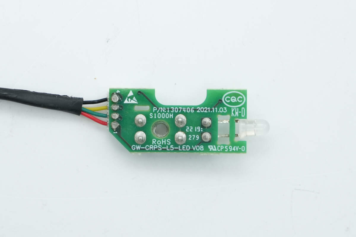
There are no components on the back.
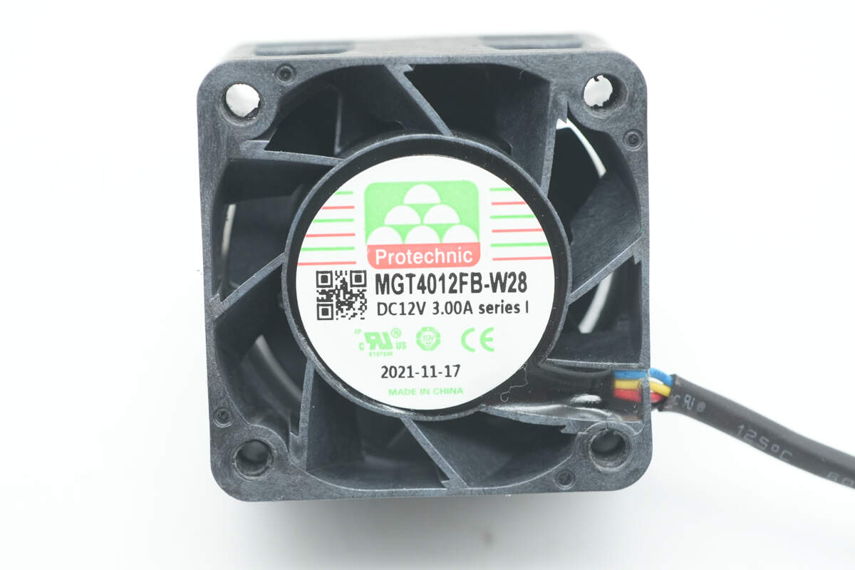
The cooling fan is from NJcon, model MGT4012FB-W28. It is rated at 12V, 3A, and is made in China.

Well, those are all components of the GreatWall 2200W 80 PLUS Platinum Server Power Supply.
Summary of ChargerLAB
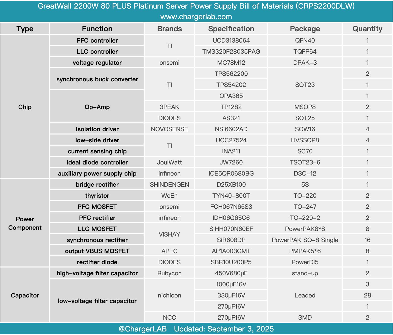
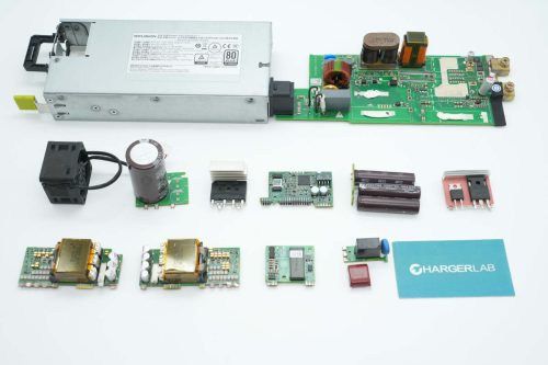
Here is the component list of the GreatWall 2200W 80 PLUS Platinum Server Power Supply for your convenience.
It supports a wide input voltage range of 100–240V and delivers a 12V output with 80 PLUS Platinum efficiency. At 220V input, the rated output power is 2200W, while at 110V input, it is limited to 1100W. The unit includes a built-in cooling fan and is equipped with a C20 inlet.
After taking it apart, we found that it uses a PFC + full-bridge LLC architecture. Both the PFC controller and LLC controller are from TI. The PFC MOSFETs are Onsemi FCH067N65S3, and the PFC rectifiers use Infineon IDH06G65C6 silicon carbide diodes.
The LLC MOSFETs are VISHAY SiHH070N60EF, driven by 3PEAK NSi6602AD isolation driver. The synchronous rectifiers are VISHAY SiR608DP, driven by TI UCC27524 drivers. High-voltage filter capacitors are from Rubycon, solid capacitors from Nichicon, and the auxiliary power chip is from Infineon. The build quality is solid, and the components are reliable.
Related Articles:
1. Teardown of EMERSON 1725W AC Power Supply (7001490-J000)
2. Teardown of Foton Aumark 3kW DC-DC Converter (SDM302BUYM)
3. Teardown of UGREEN Nexode 20000mAh 130W Power Bank with Built-in USB-C Cable (PB723)