Introduction
This teardown features a server power supply unit from Gospower, model G1232-1300WND, part of the LVDC series. The power module supports a 12V DC output with a maximum output current of 108A. The LVDC series is designed for server applications using a –48V DC battery pack input. The product is 80 PLUS Gold certified and supports a DC input voltage range of 36–72V. When the input voltage is between 36V and 40V, the power supply is derated to 1000W. When the input is within 40–72V, the rated output power is 1300W.
The power supply includes a 12V standby output with a maximum current of 2.1A. The module features a long rectangular metal enclosure. The input side is equipped with a cooling fan, a handle, status indicator lights, and a DC input connector. The output side includes a gold-finger edge connector. Internally, the power supply adopts an LLC resonant converter architecture to enable efficient power conversion. The following section presents a detailed teardown of this server power supply, examining its internal design and components.
Product Appearance
The power supply features a metal enclosure with grounding spring contacts installed on the front.
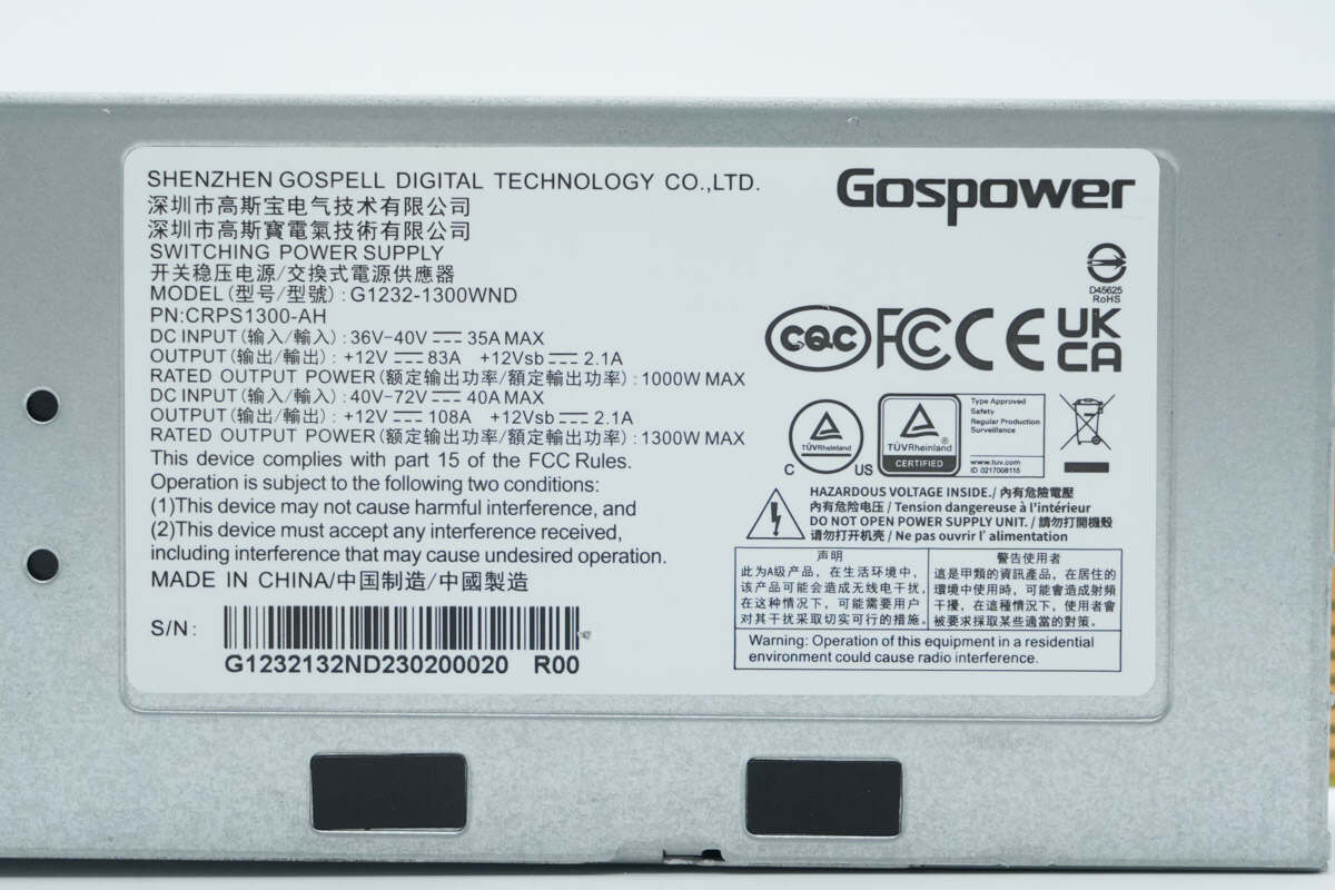
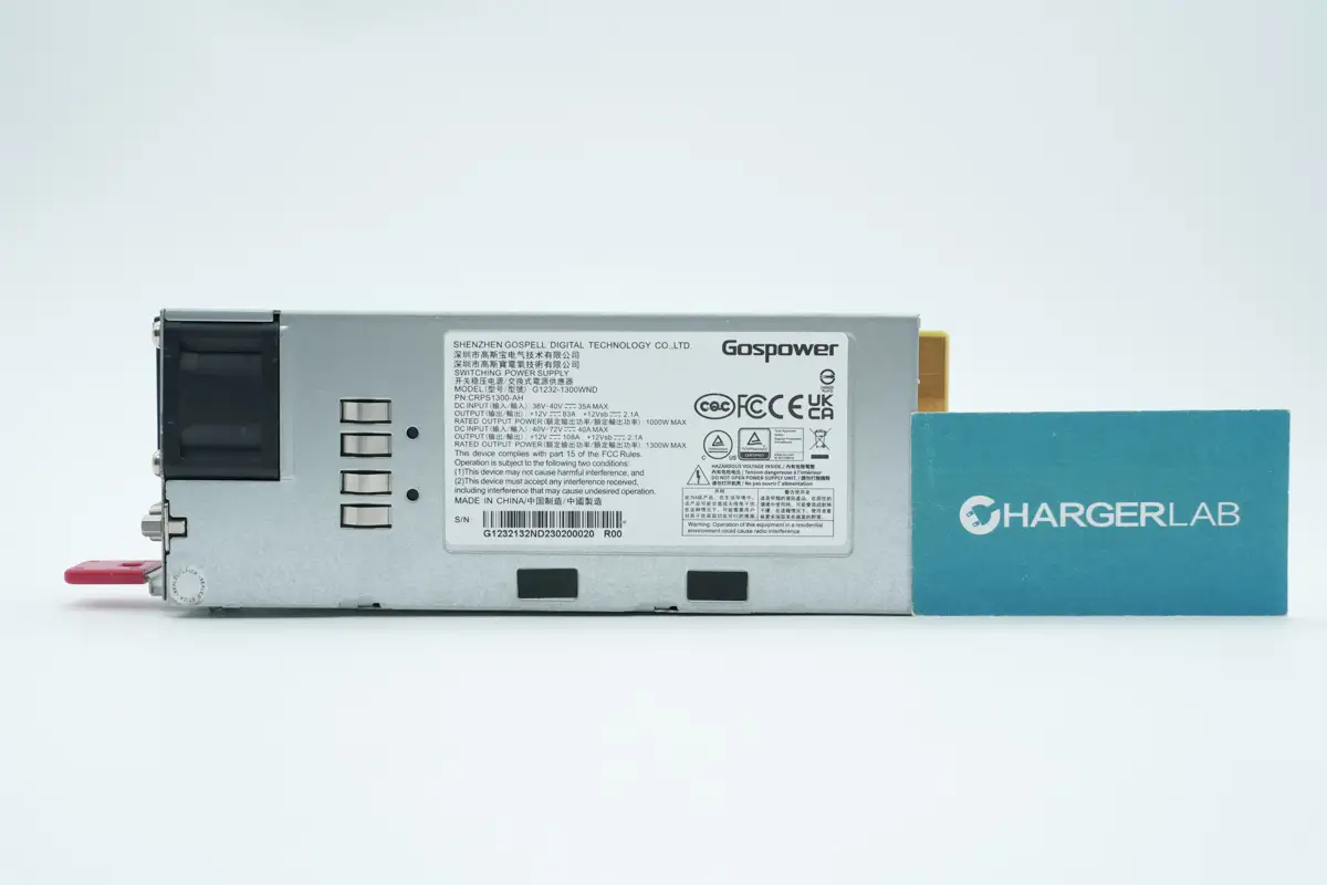
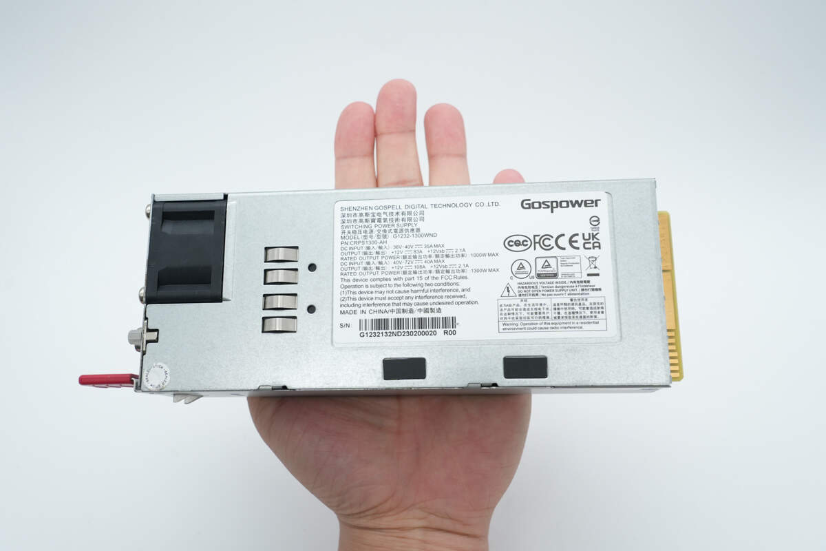
Close-up of the Nameplate.
Model: G1232-1300WND
Input: 36–40V 35A MAX
Output: +12V 83A, +12Vsb 2.1A
Rated Output Power: 1000W MAX
Input: 40–72V 40A MAX
Output: +12V 108A, +12Vsb 2.1A
Rated Output Power: 1300W MAX
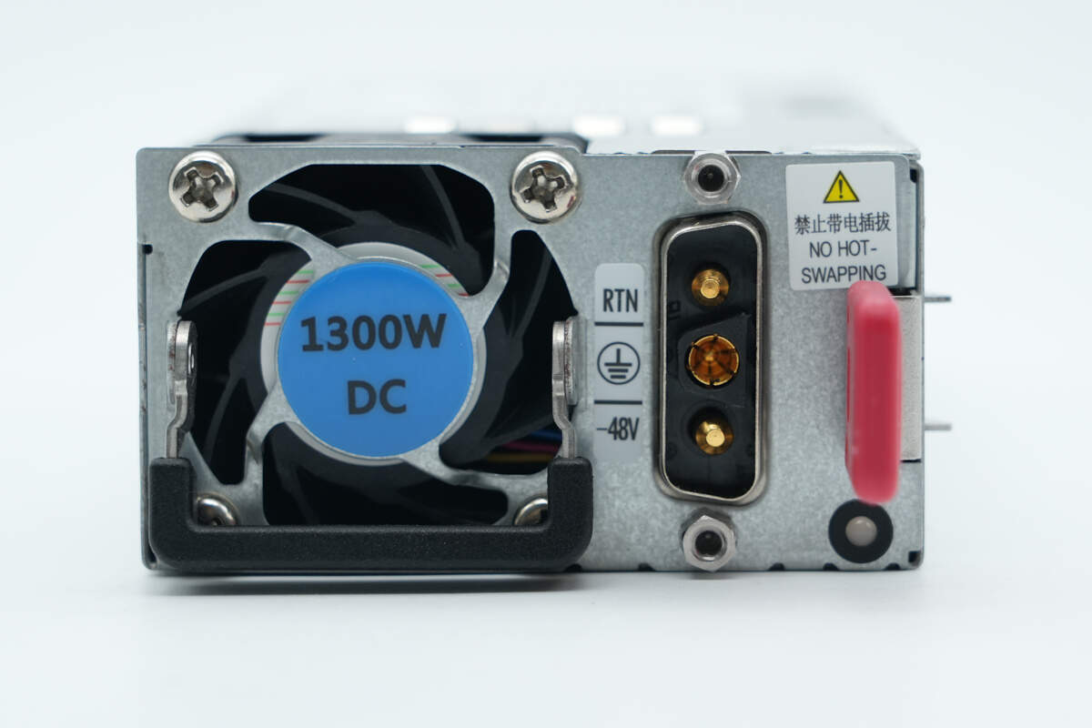
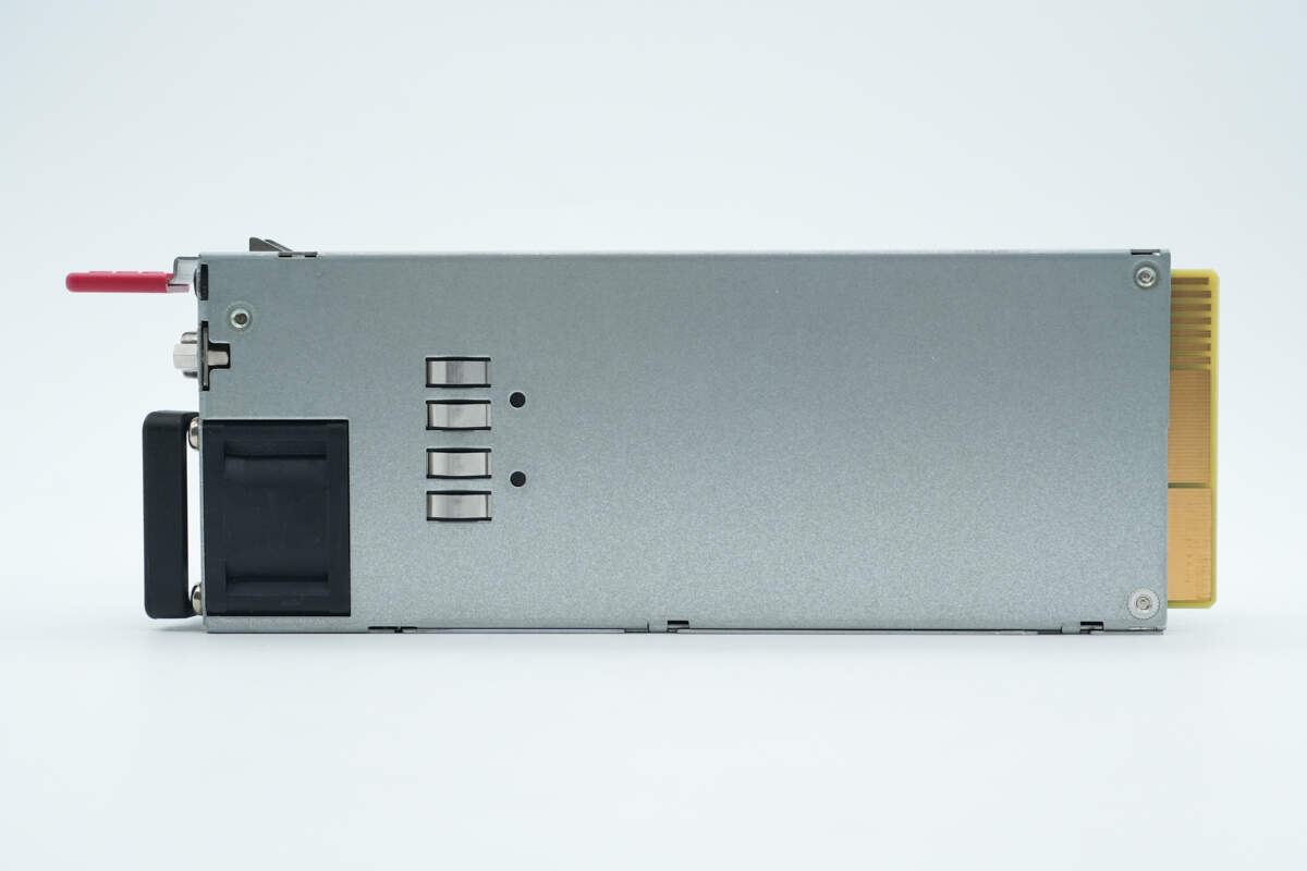
The input side features a handle, cooling fan, DC input socket, power indicator LED, and a release latch.
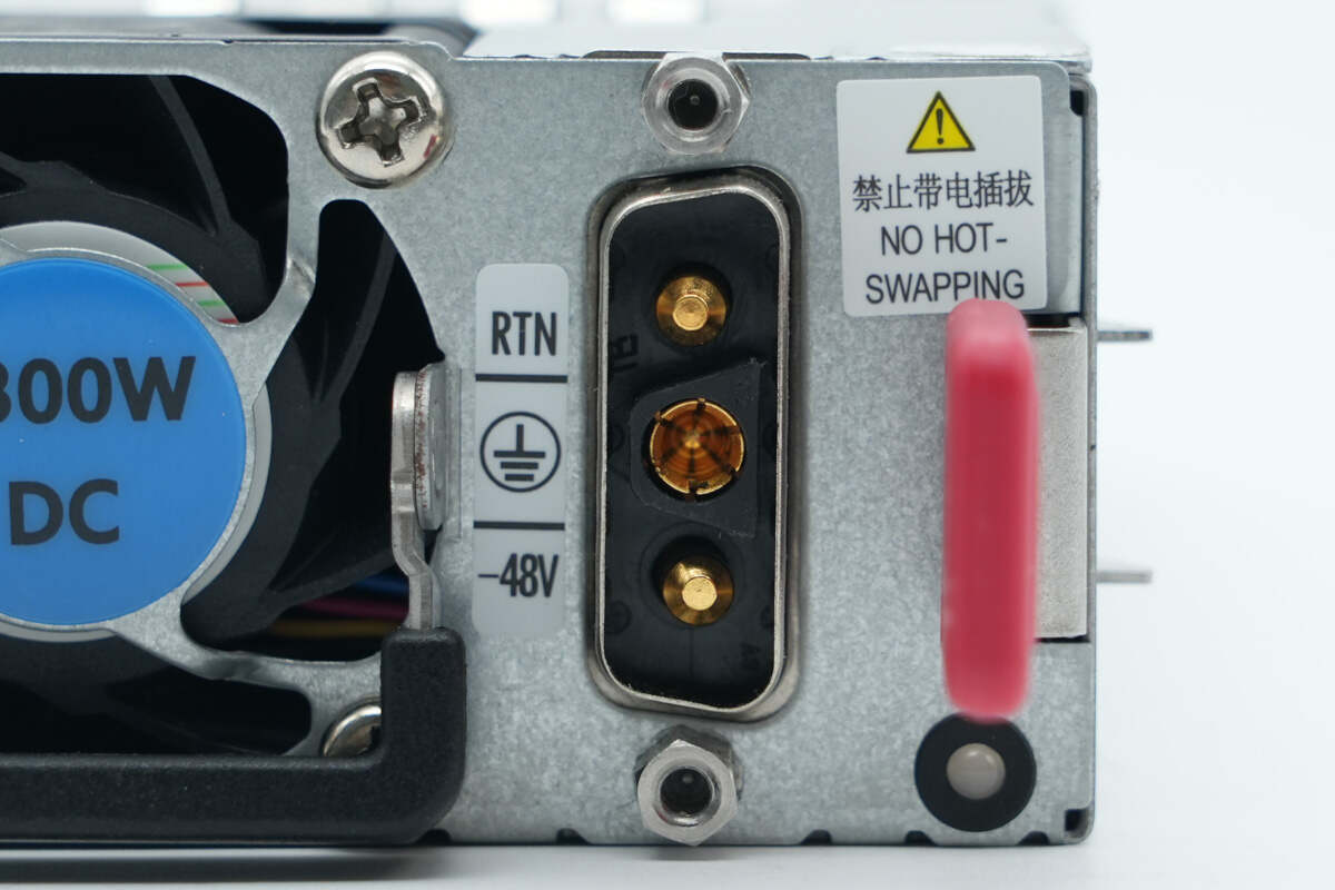
To the left of the DC input socket, grounding and polarity symbols are labeled. Mounting screws are positioned above and below the socket.
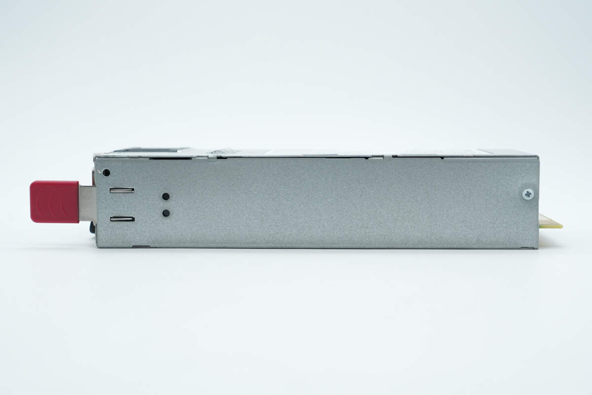
The side features retaining clips and a screw.
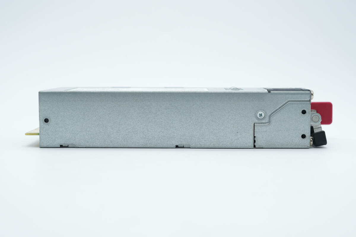
There is also a screw on the opposite side.
The back features grounding spring contacts.
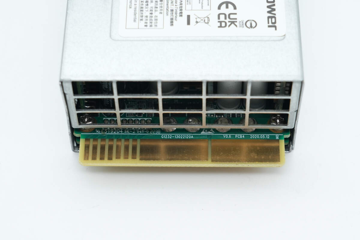
Close-up of the gold finger connector on the output side.
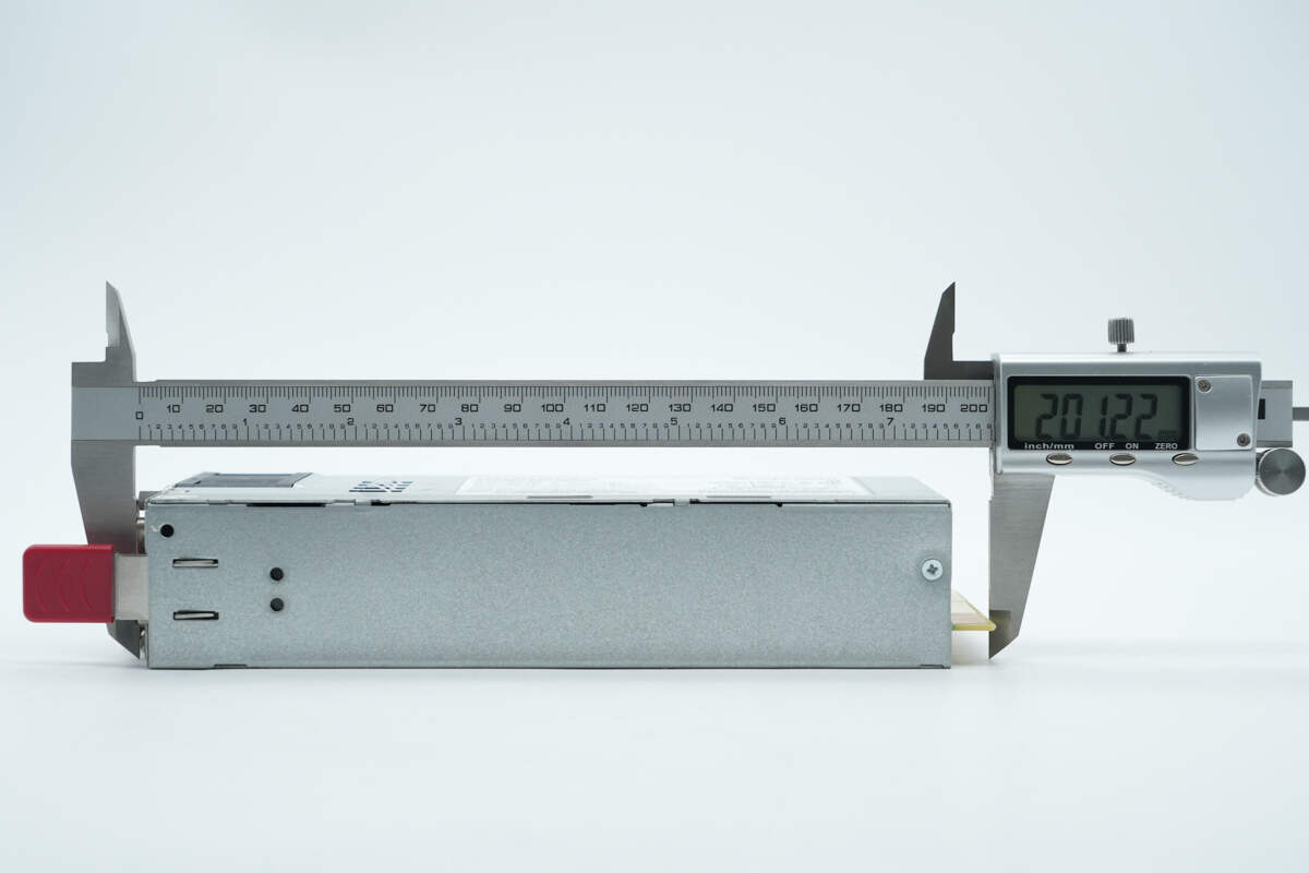
The length is about 201 mm (7.91 inches).
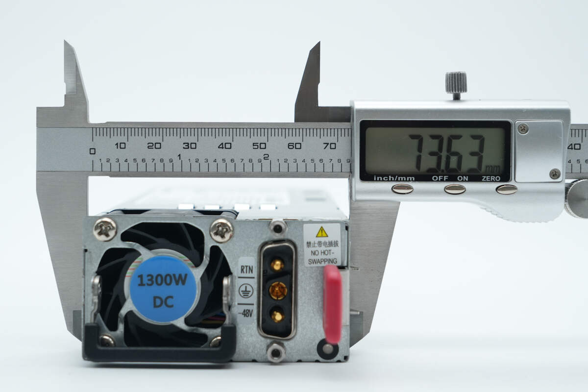
The width is about 73.6 mm (2.9 inches).
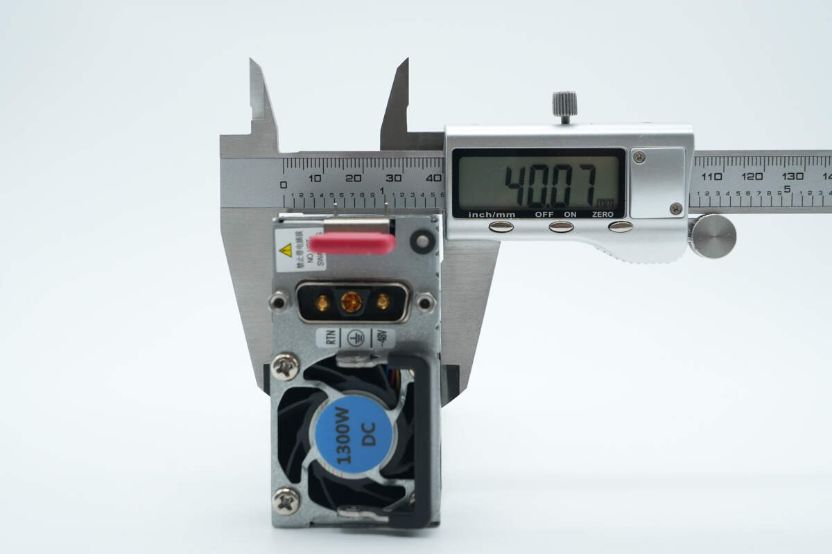
The thickness is about 40.1 mm (1.58 inches).
That's how big it is in the hand.
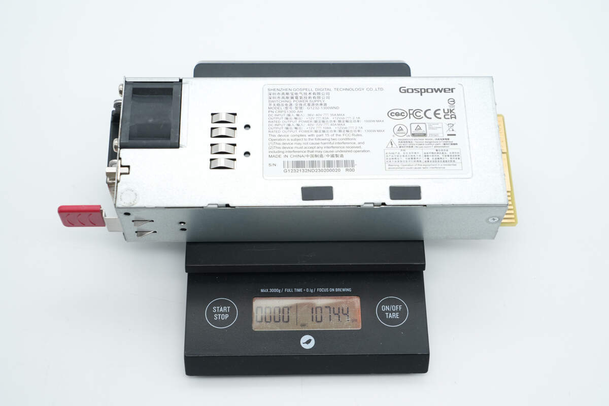
The weight is about 1074 g (37.88 oz).
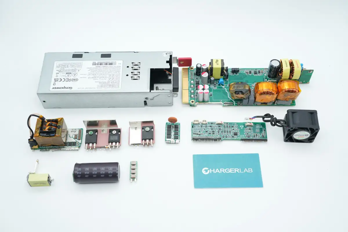
Teardown
Next, let's take it apart to see its internal components and structure.
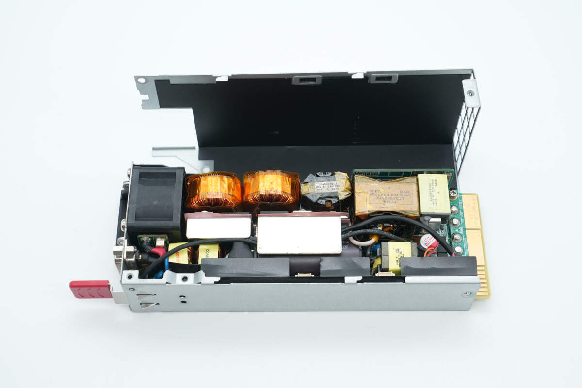
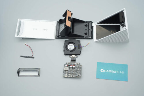
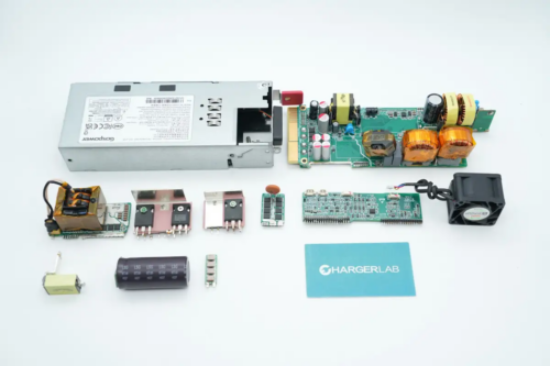
First, remove the screws to open the enclosure. Inside, a black Mylar sheet is used for insulation.
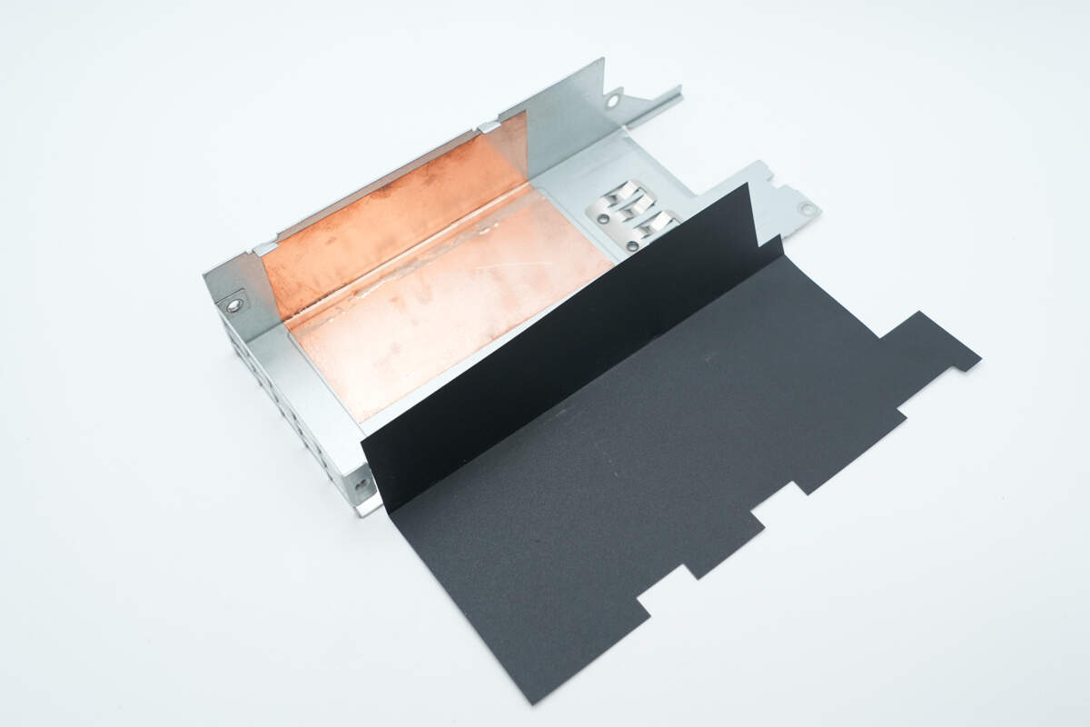
The inner side of the Mylar sheet is a copper foil for enhanced shielding.
The PCBA module is secured with screws.
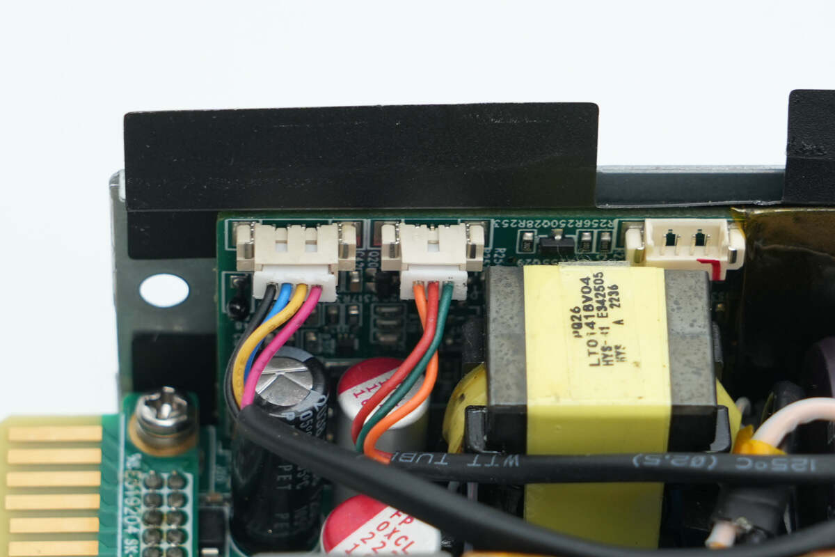
The cooling fan and LED indicator are connected via plug-in connectors.
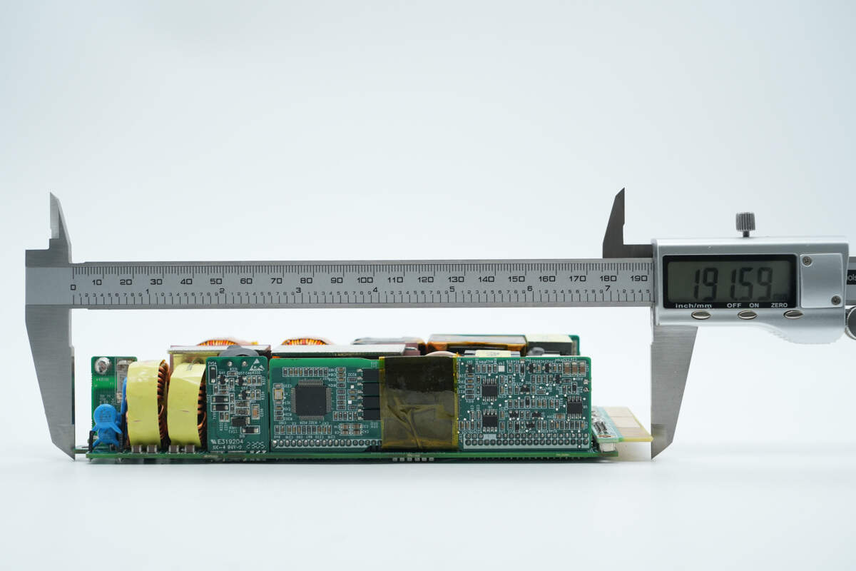
The length of the PCBA module is about 191.6 mm (7.54 inches).
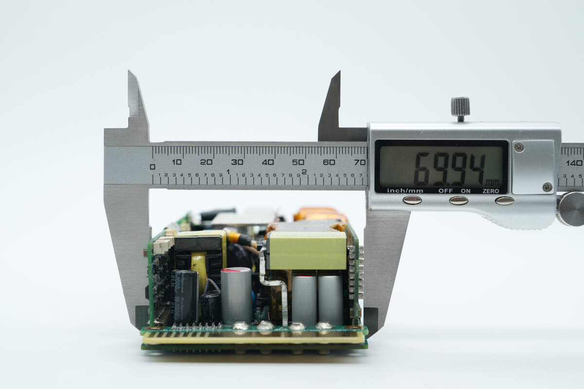
The width is about 69.9 mm (2.75 inches).
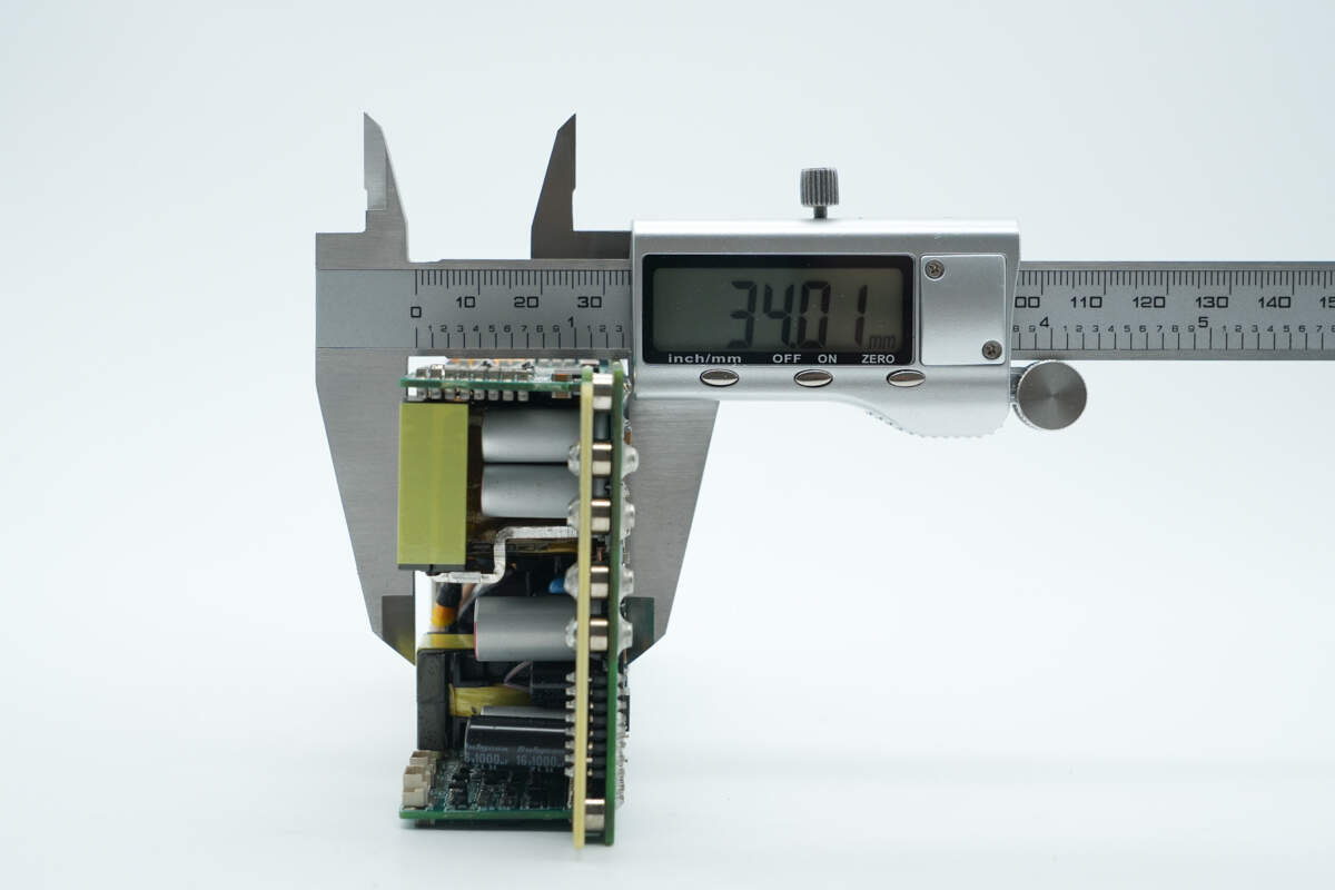
The thickness is about 34 mm (1.34 inches).
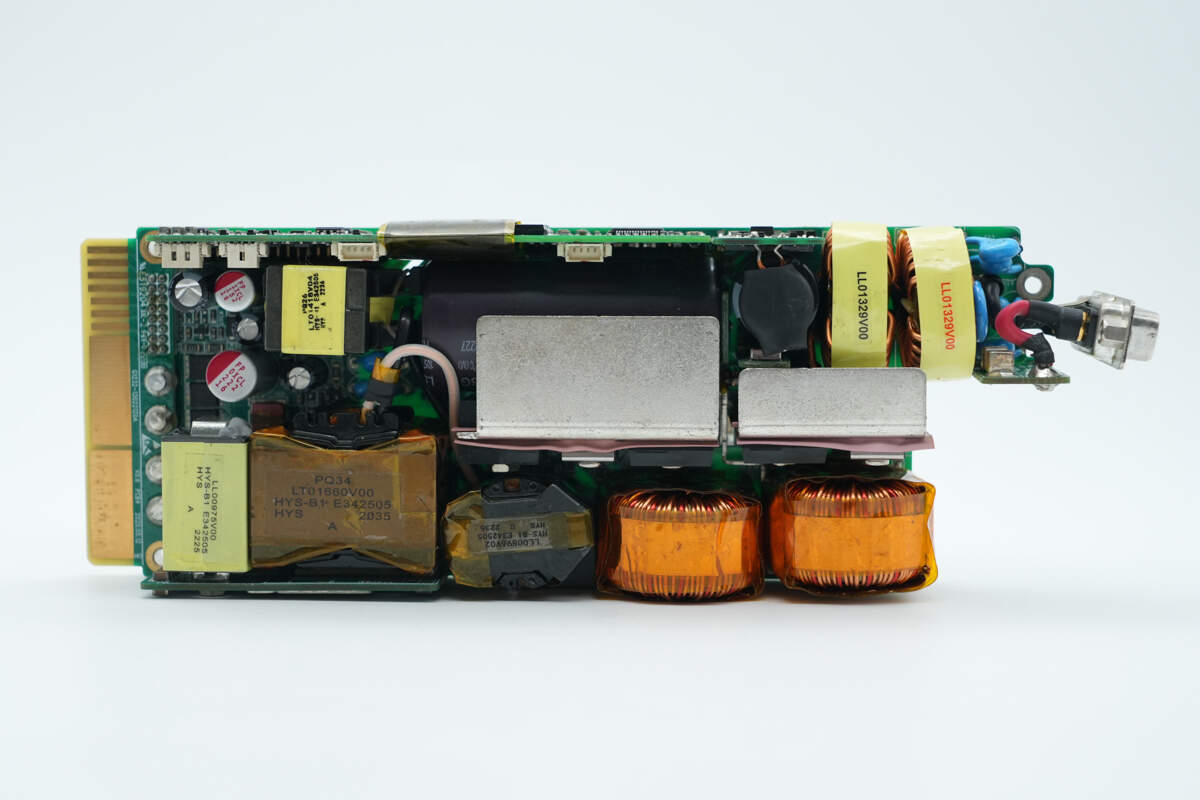
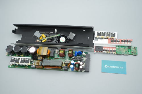
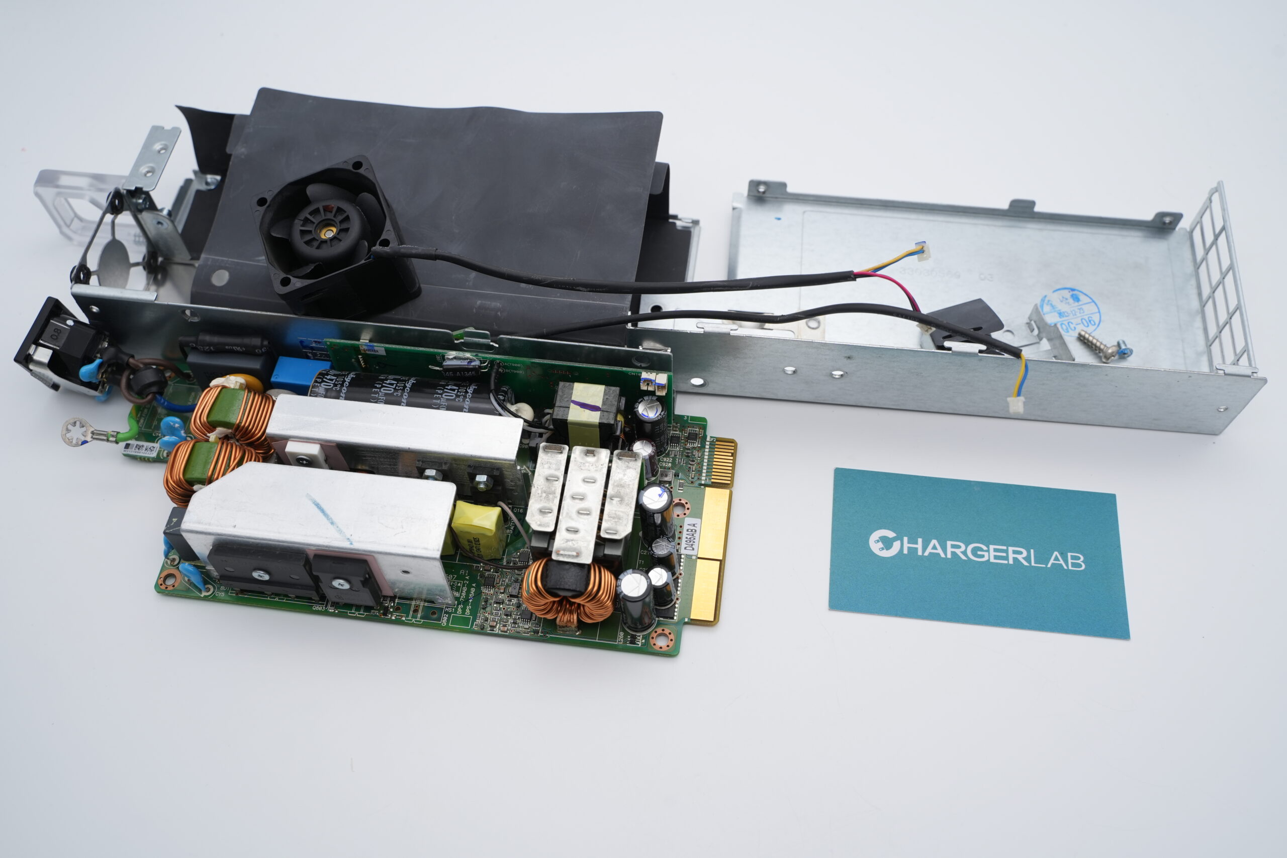
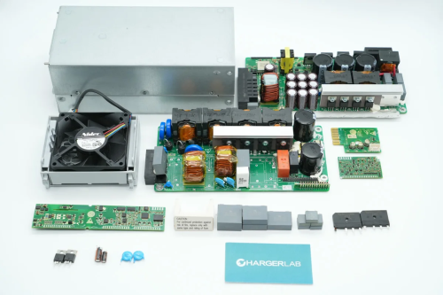
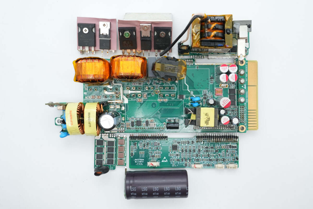
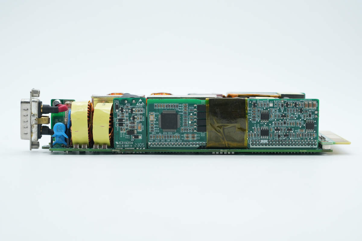
On the upper right side of the front of the PCBA module, there is a small vertical PCB with a fuse. The input section includes Y capacitors, a varistor, common mode chokes, an NTC thermistor, VBUS MOSFETs, and filter capacitors.
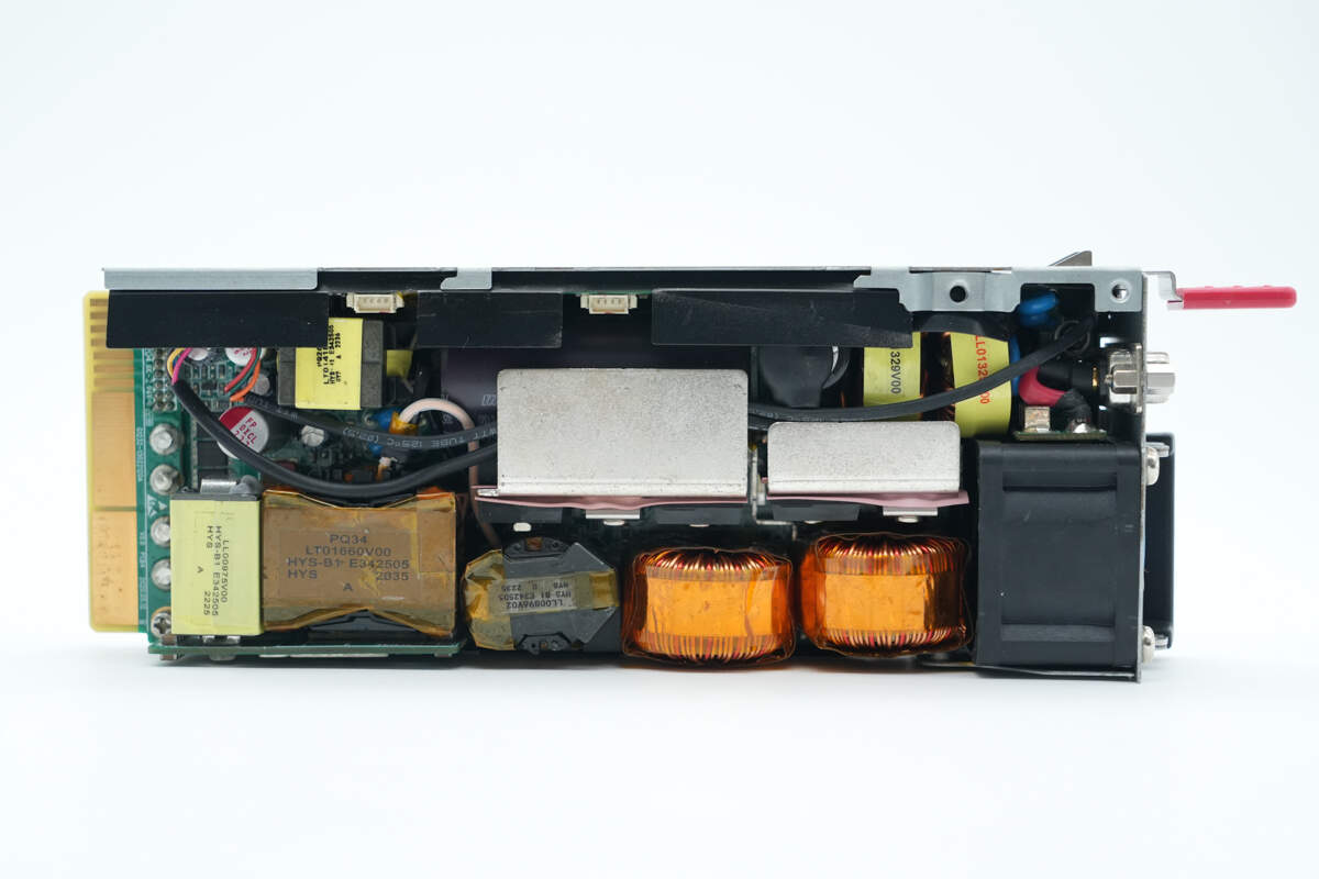
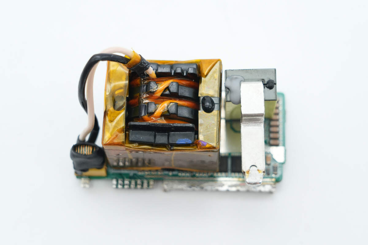
Below are boost MOSFETs and rectifiers, boost inductors, a resonant inductor, a transformer, filter inductors, a standby power transformer, and filter capacitors.
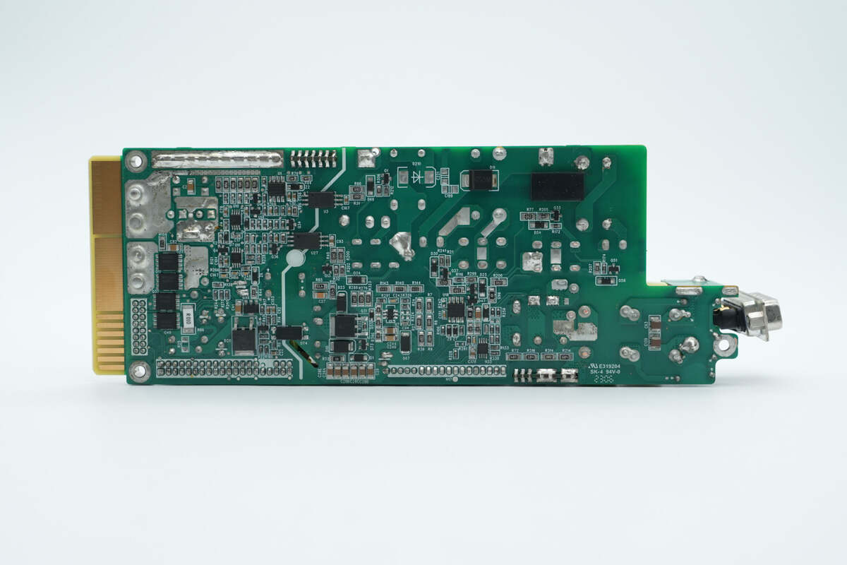
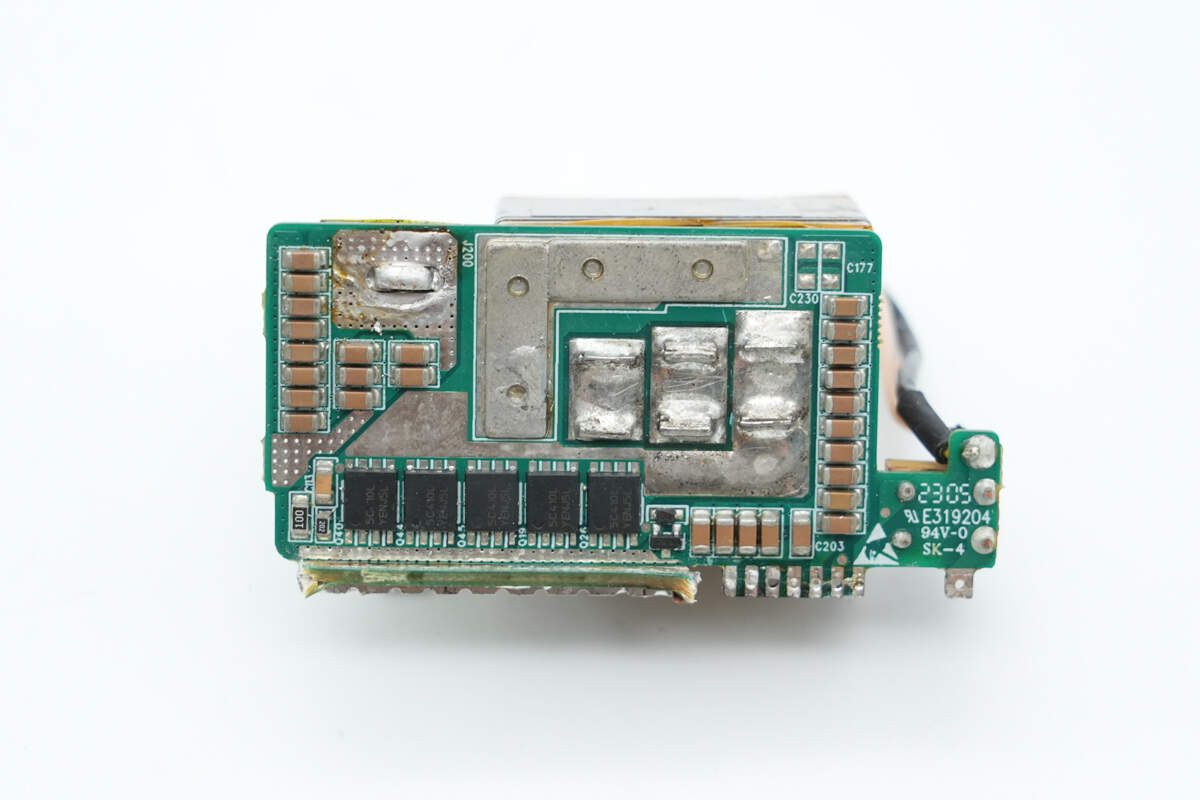
On the back side, there are gate drivers, Op-Amps, the standby power supply main controller, standby power MOSFETs, optocouplers, rectifier diodes, and output control MOSFETs.
Remove the small PCBs and other components mounted on the main PCBA.
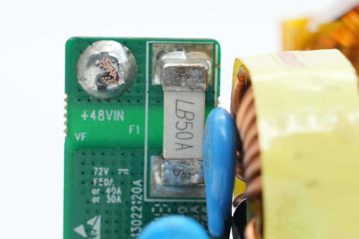
The SMD fuse at the input side is from Lanbao, with a rating of 50A.
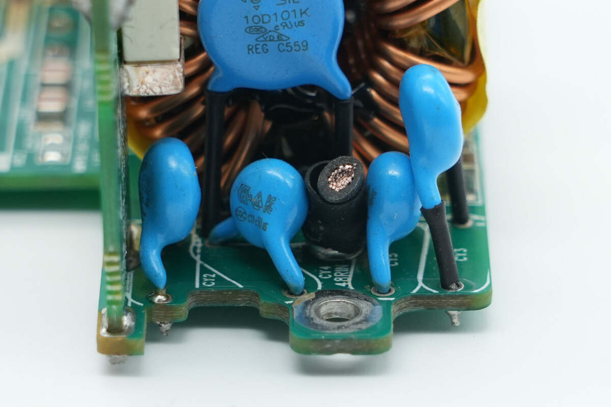
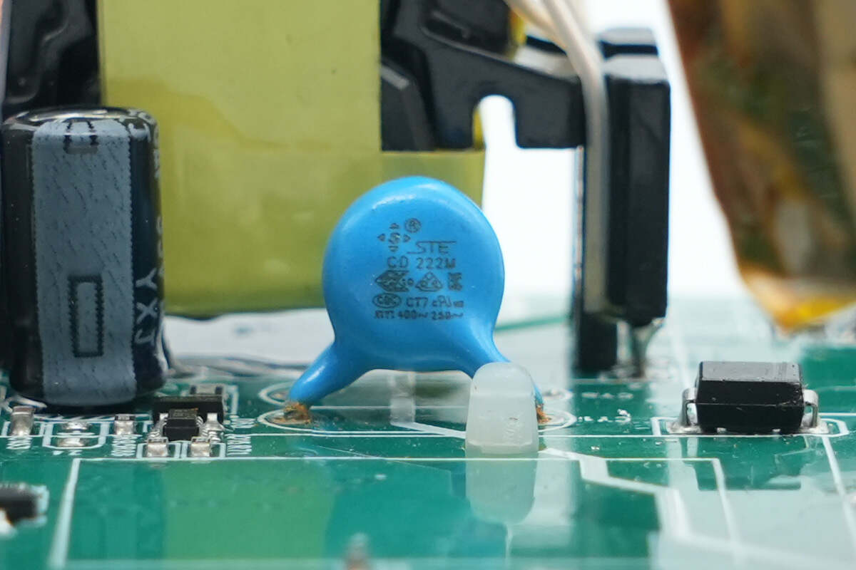
Close-up of the four blue Y capacitors.
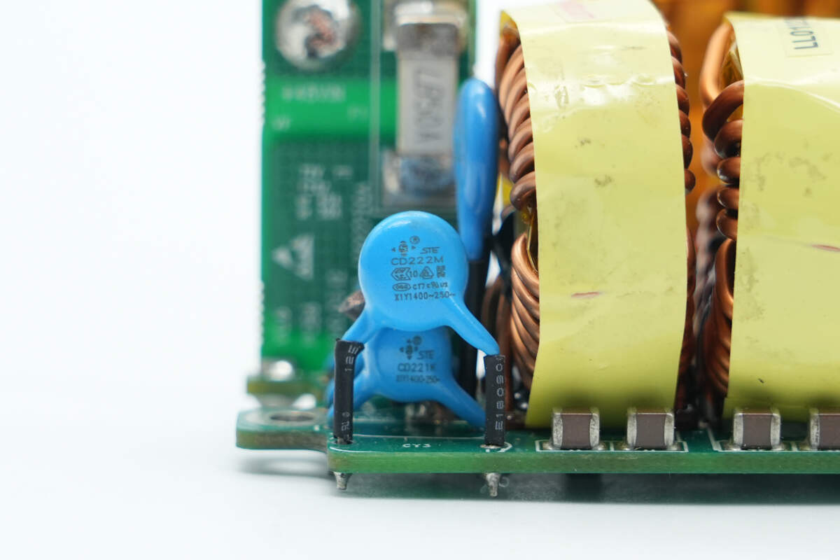
The blue Y capacitors are manufactured by STE.
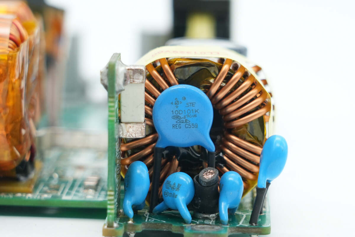
The varistor is manufactured by STE, model 10D101K, and is used to absorb overvoltage surges.
On this side, there are common mode chokes, a small PCB with VBUS MOSFETs, and the control PCB.
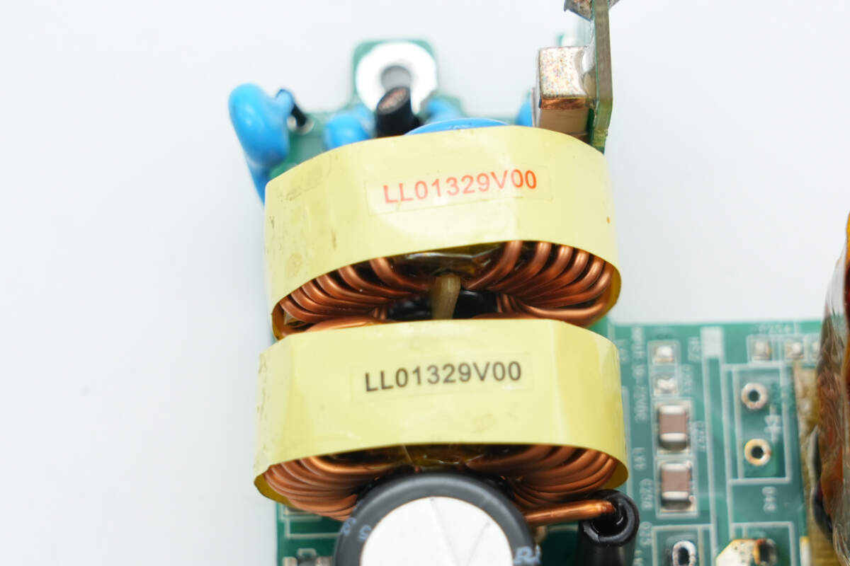
The common mode chokes are wound with magnet and insulated wires.
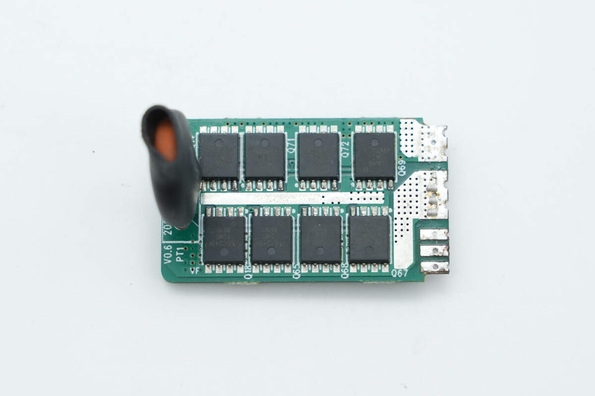
The VBUS MOSFETs are located on the front of the vertical small PCB.
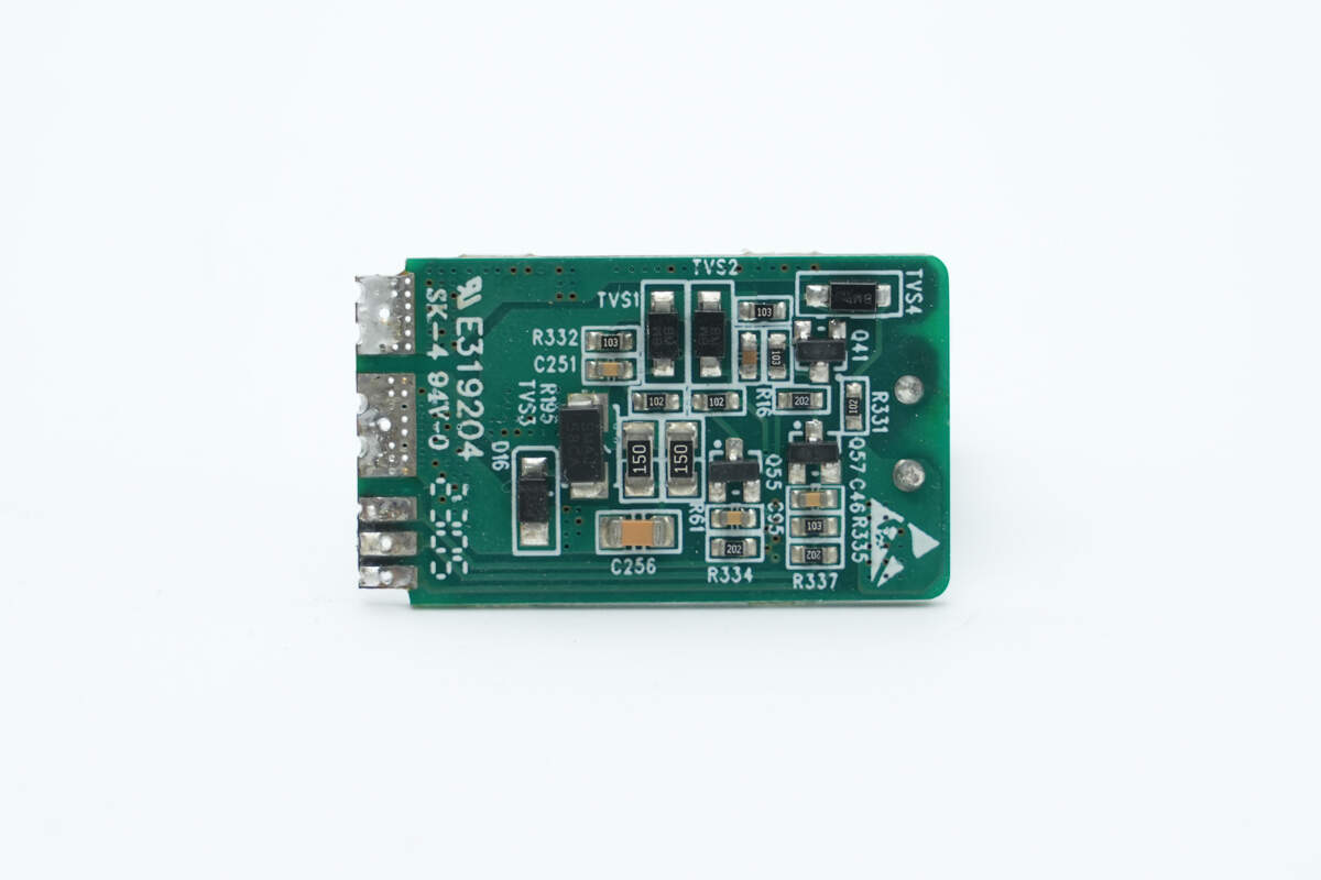
The back side is equipped with TVS diodes and transistors.
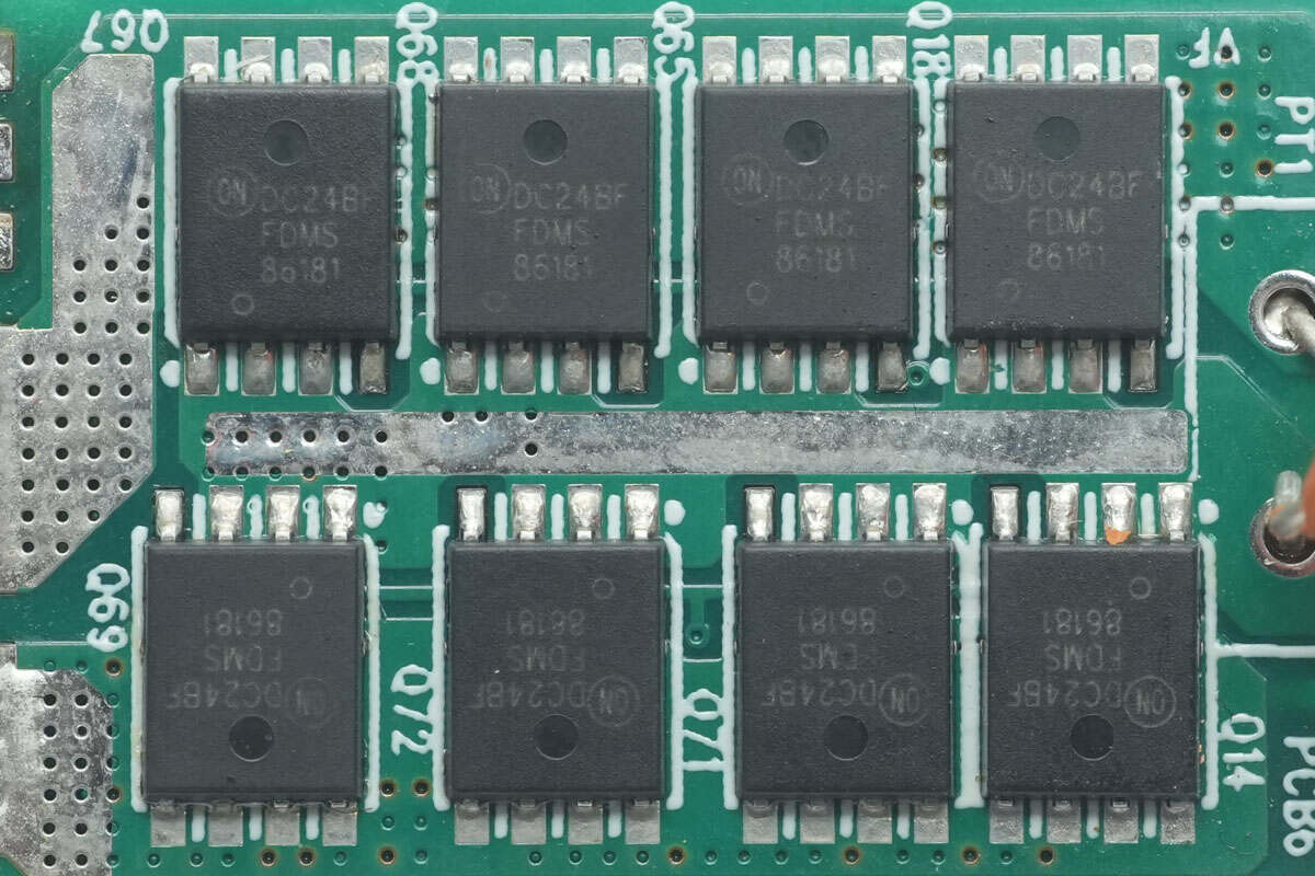
The VBUS MOSFETs are from Onsemi, model FDMS86181. They are N-channel MOSFETs with a voltage rating of 100V, an on-resistance of 4.2mΩ, and come in a PQFN8 package.

The thermistor, marked with MZ21, is used to suppress inrush current during power-up.

The filter capacitor is from Rubycon, rated at 100V and 330μF.
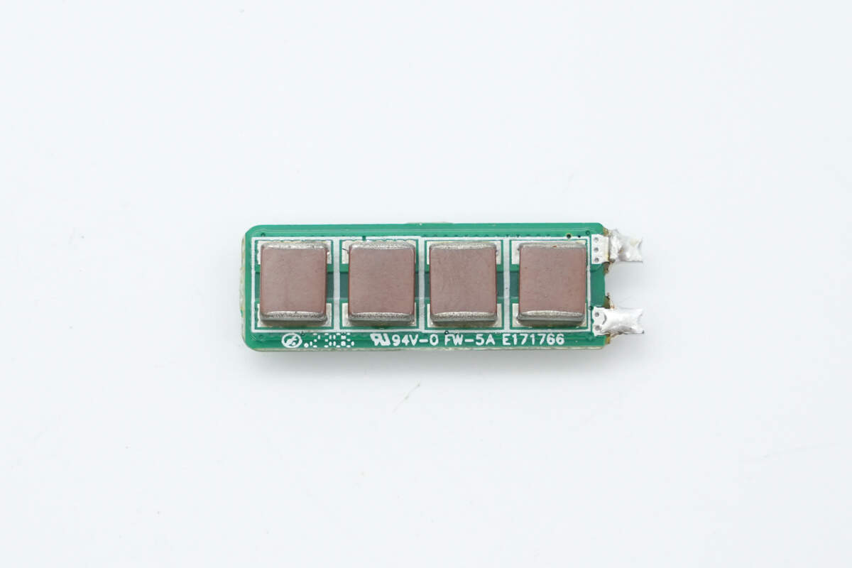
The MLCC capacitors are soldered onto a separate PCB.

There are four MLCC capacitors on each side, front and back.
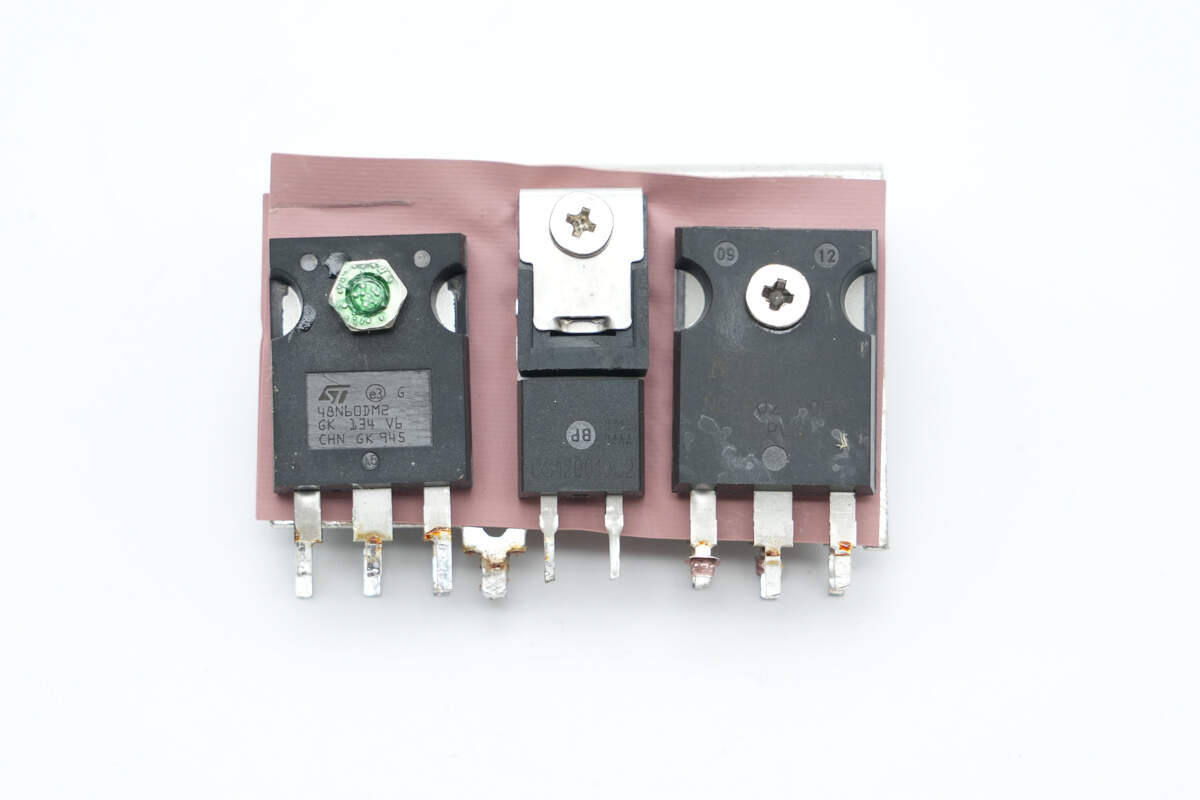
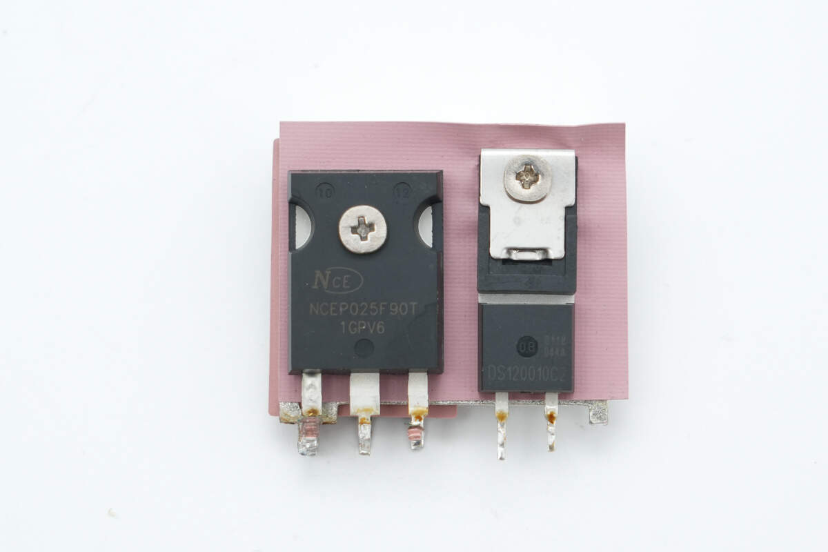
On the front side of the heatsink, there is an LLC MOSFET, a SiC diode, and a boost MOSFET.
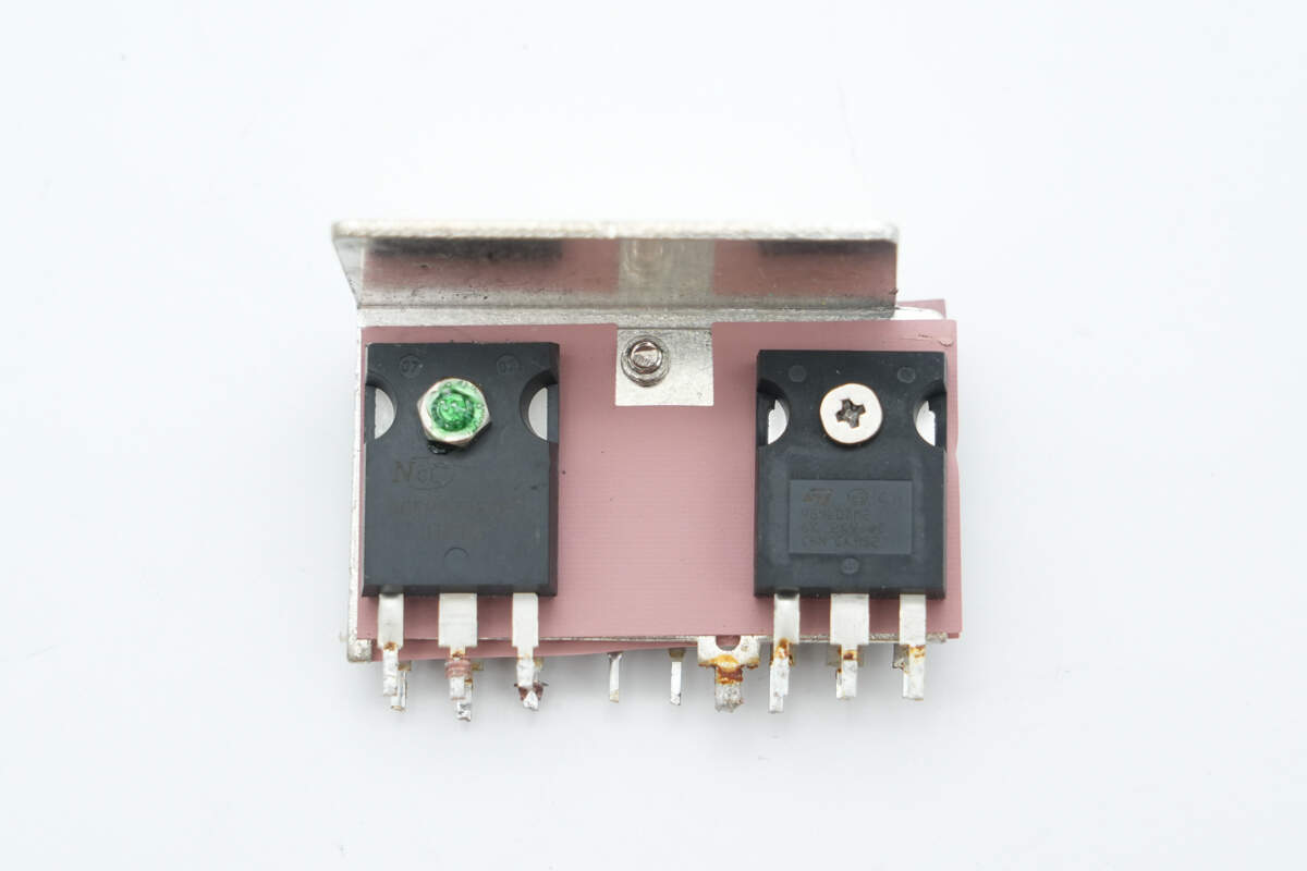
On the back side, there is a boost MOSFET and an LLC MOSFET.
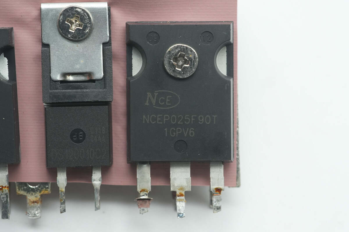
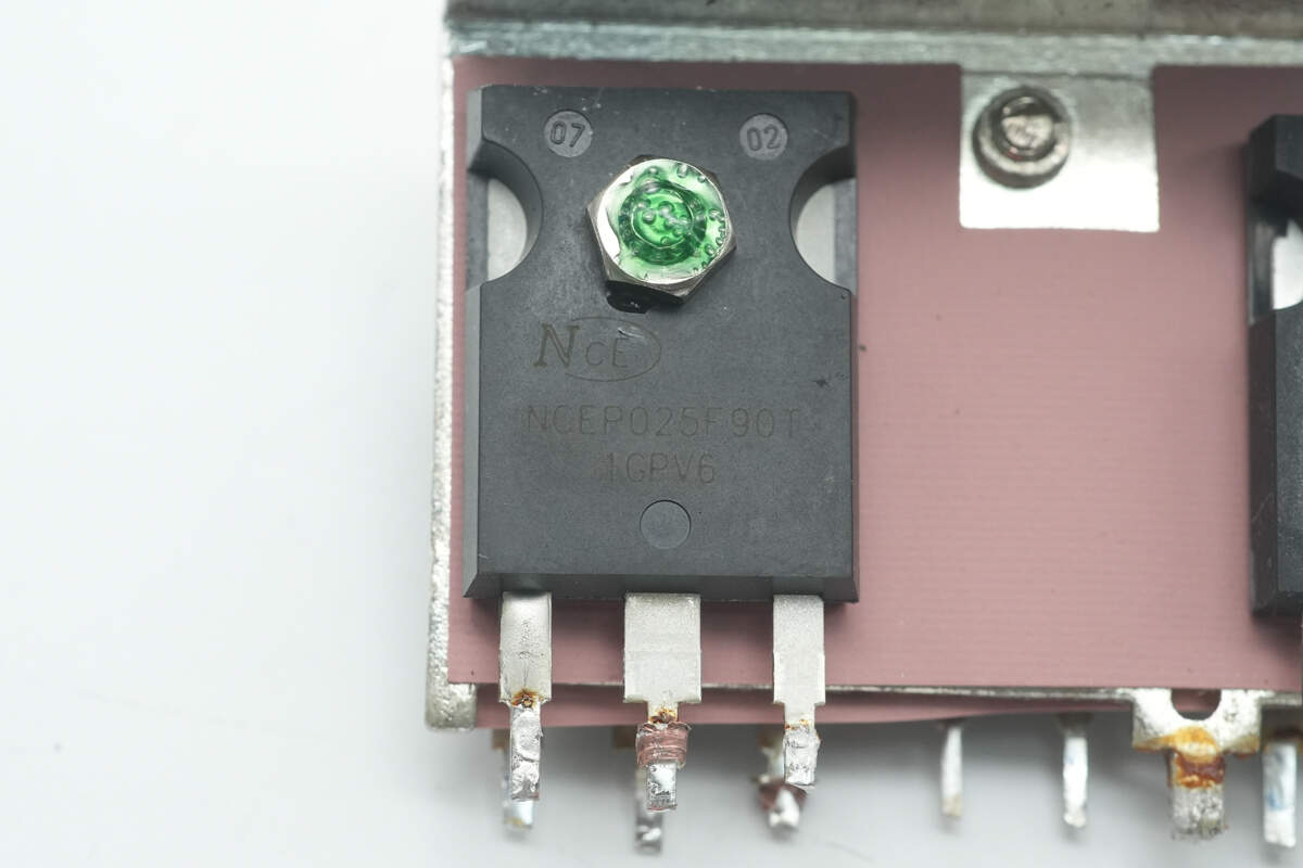
The boost MOSFET is from NCE, model NCEP025F90T. It is an N-channel MOSFET with a voltage rating of 250V, an on-resistance of 14mΩ, and comes in a TO-247 package.
The boost MOSFETs on the back are the same model, with two devices connected in parallel.

The SiC diode is manufactured by Sanan and marked with DS120010C2. Its model number is SDS120J010C2, featuring a voltage rating of 1200V and a current rating of 13A. It is packaged in a TO-220-2L enclosure.
Another heatsink on the front side is equipped with the same model of boost MOSFET and SiC diode.
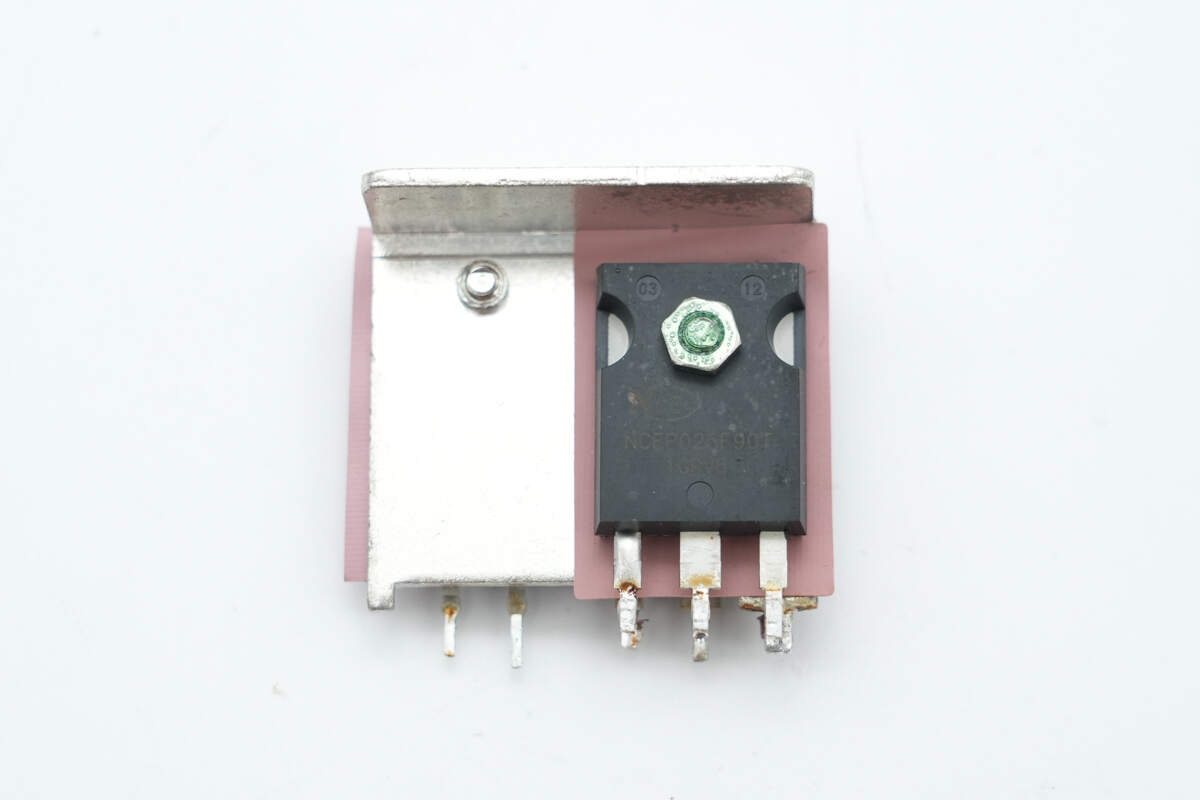
The reverse side is fitted with the same model of boost MOSFET.
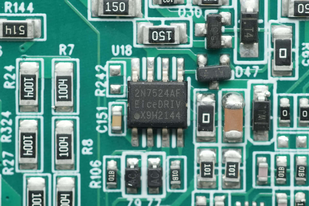
The driver is manufactured by Infineon, model 2EDN7524F. It integrates two independent low-side drivers, supports a drive current of 5A, and is suitable for both MOSFET and GaN applications. It comes in a DSO-8 package.

Close-up of the current-sensing resistor used for input current measurement.
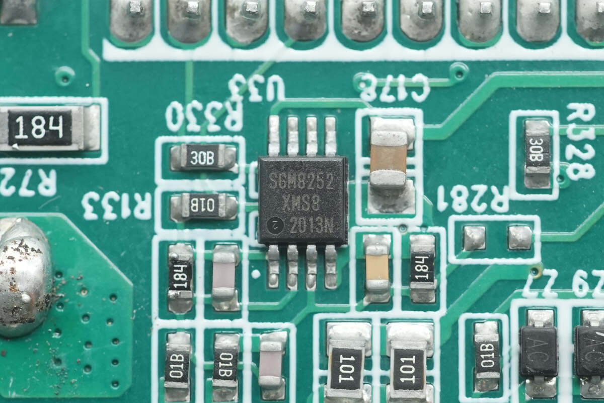
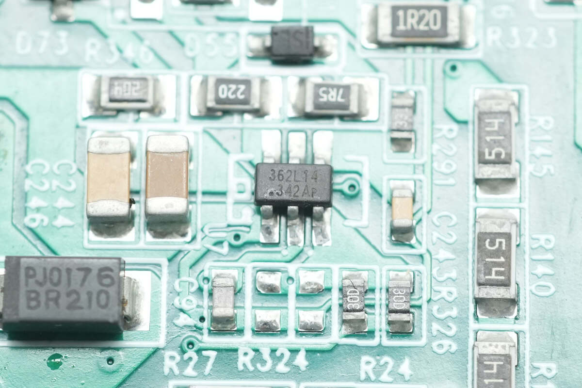
The Op-Amp is manufactured by SGMICRO, model SGM8252. It is a high-precision, low-noise, rail-to-rail output op-amp housed in an MSOP-8 package.
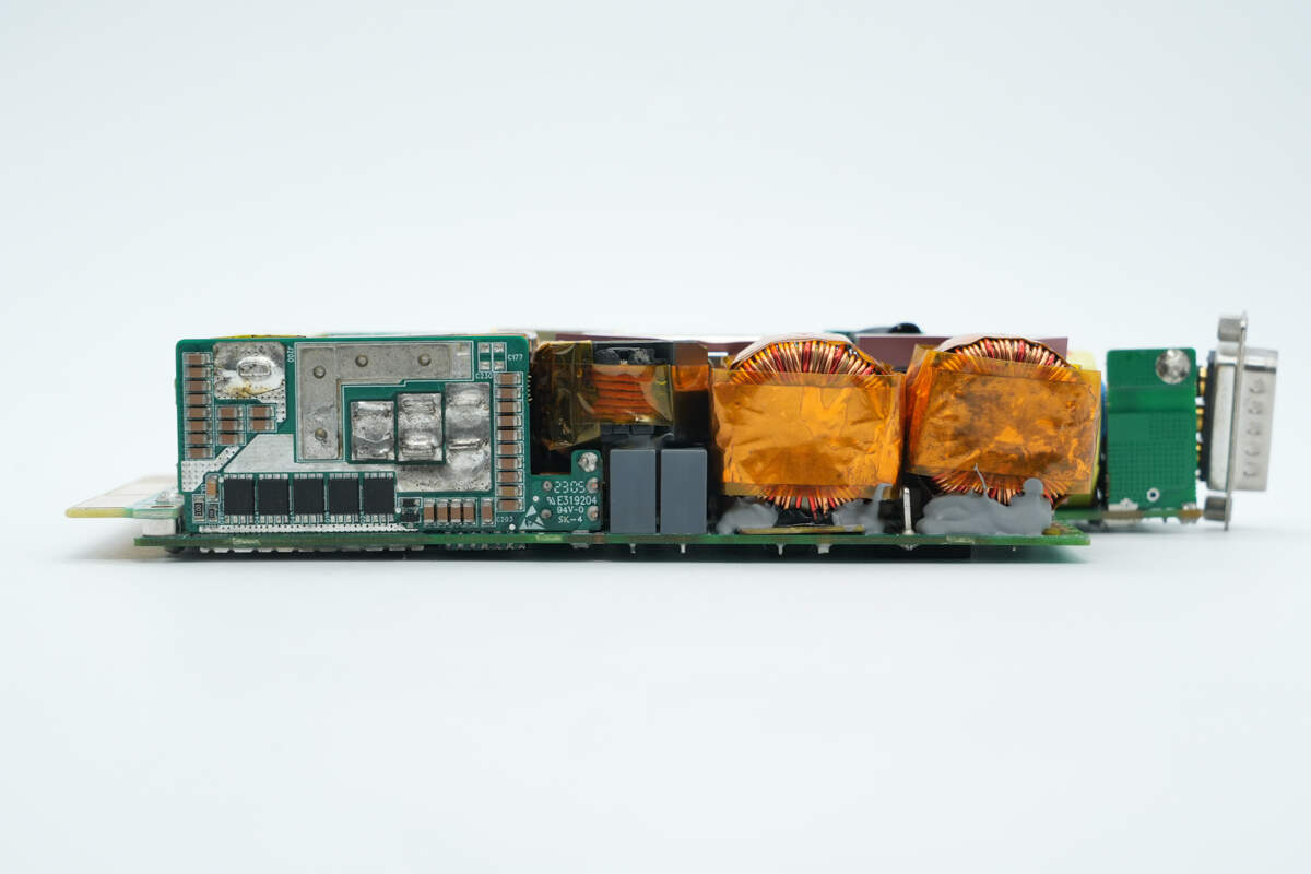
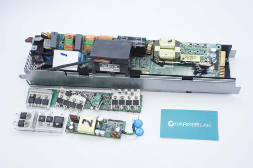
On this side of the PCBA module, there is a synchronous rectification PCB, a resonant inductor, resonant capacitors, and boost inductors.
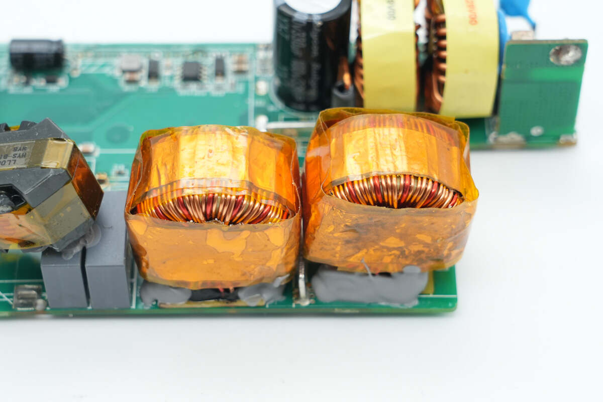
The boost inductors are wound with enameled wire and wrapped with copper foil shielding.
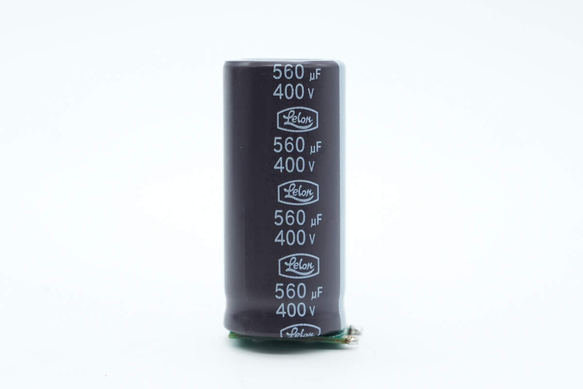
The high-voltage filter capacitor is manufactured by Lelon, with a rating of 560μF 400V.
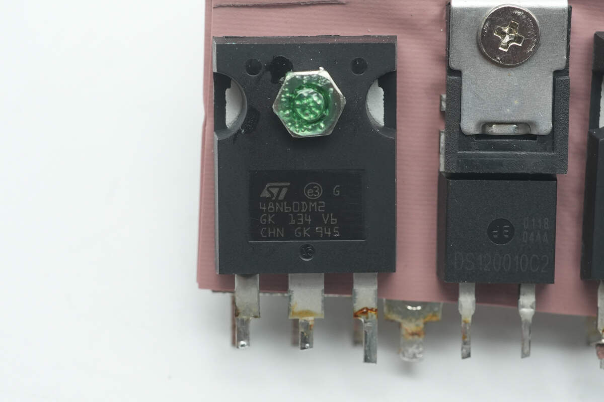
The LLC MOSFET is manufactured by STMicroelectronics, model STW48N60DM2. It is an NMOS transistor with a voltage rating of 600V and an on-resistance of 65mΩ, packaged in a TO-247 case.
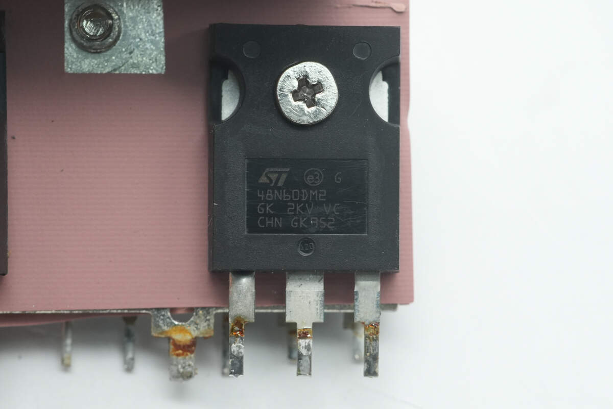
The other LLC MOSFET has the same model number.
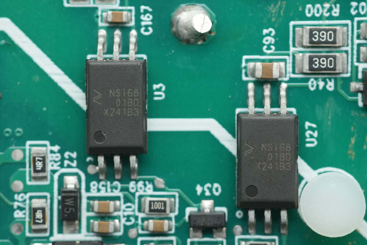
The isolation drivers are from NOVOSENSE, model NSi6801BD. They are single-channel isolated gate drivers compatible with optocoupler input, supporting IGBT, MOSFET, and GaN applications. They feature a peak source/sink current of 5A and are housed in SOW6 packages.
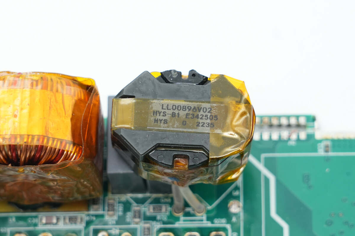
The resonant inductor is wound with Litz wire, and the magnetic core is insulated with adhesive tape.
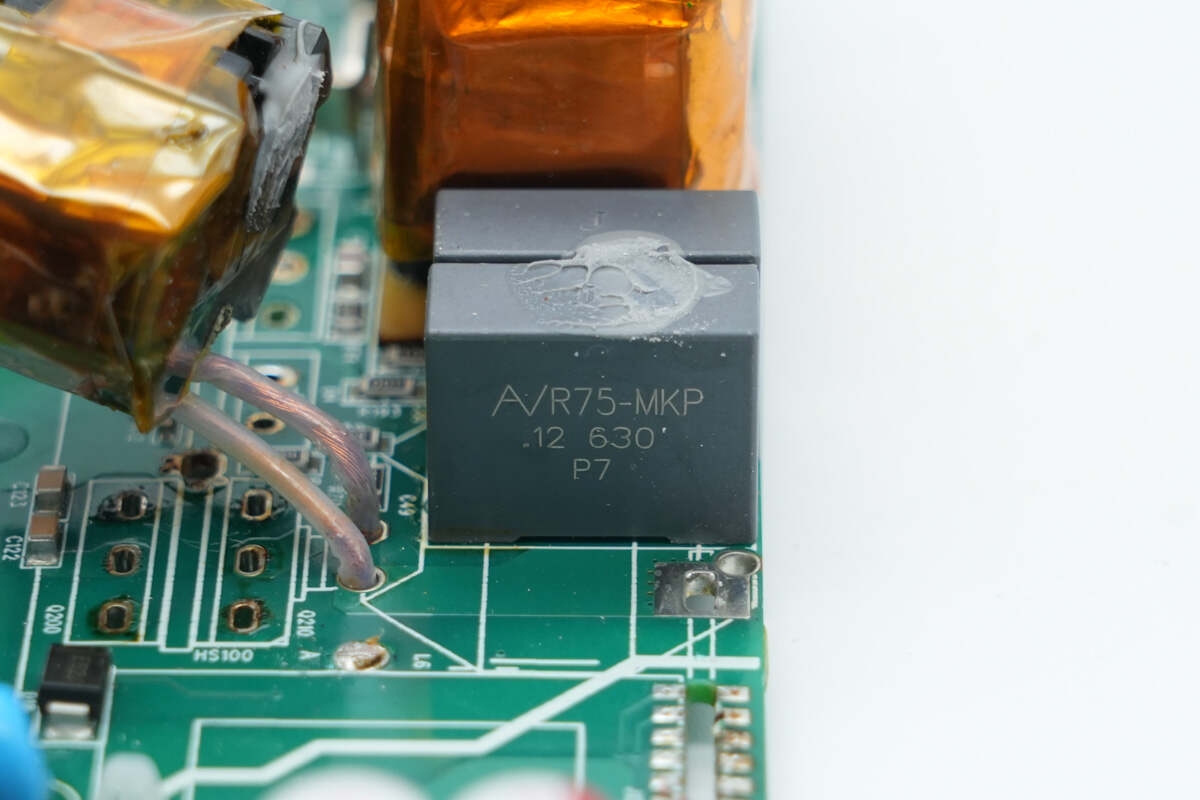
The resonant capacitors are rated at 0.12μF, 630V.

At the output, there is a standby power transformer, a solid capacitor, and a filter inductor.
The transformer and filter inductor are soldered onto a small PCB.
The back of the small PCB is equipped with MLCC capacitors and synchronous rectifiers.
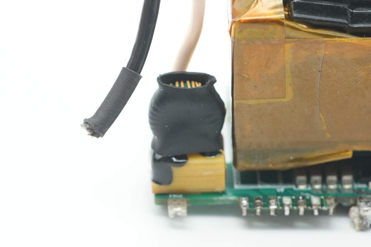
The current transformer is wound around a magnetic core and insulated with heat shrink tubing.

The transformer uses a PQ34 magnetic core, which is insulated with wrapping tape. The primary winding is made with Litz wire, while the secondary winding is formed by soldered copper strips.
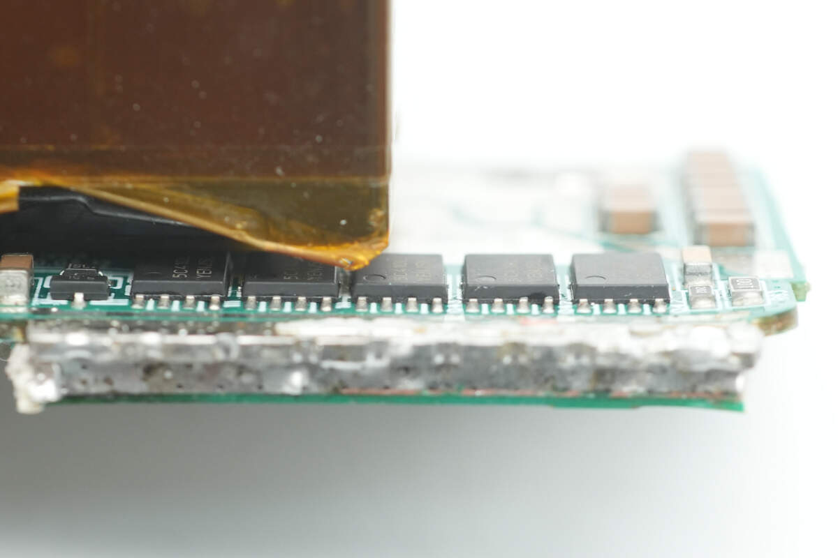
Five synchronous rectifiers are mounted below the transformer.
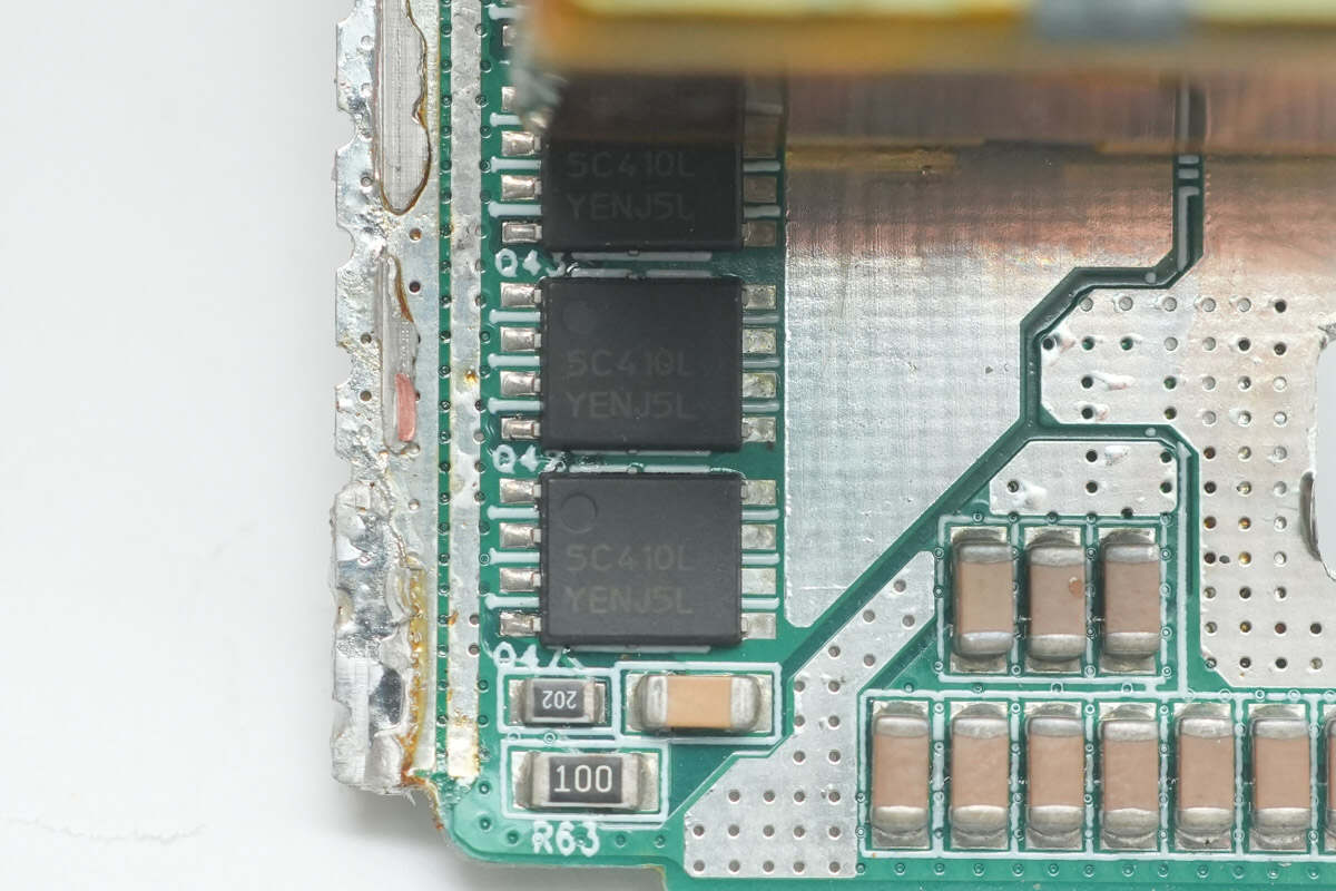
The synchronous rectifiers are from Onsemi, marked with 5C410L. Their model number is NTMFS5C410NL. They are NMOS transistors with a voltage rating of 40V and an on-resistance of 0.82mΩ, packaged in a DFN5 case.
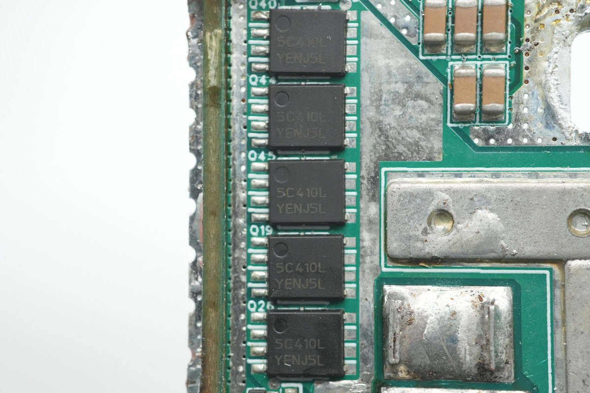
The five synchronous rectifiers on the opposite side of the small PCB have the same model number.
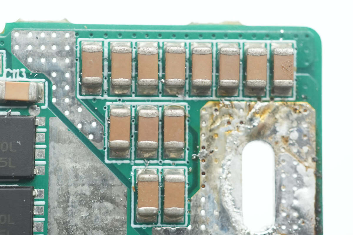
Close-up of the MLCC capacitors.
Close-up of the output inductor.
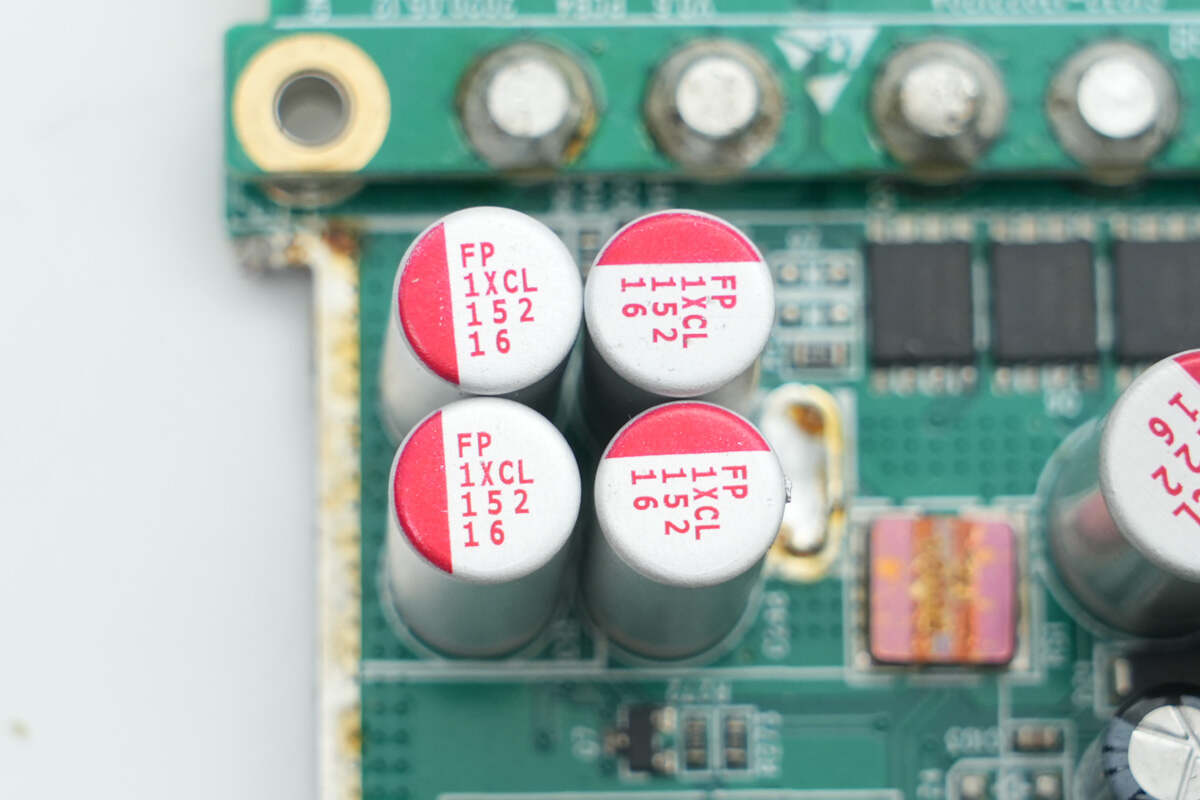
The filter capacitors are manufactured by Nichicon, with a rating of 1500μF 16V.
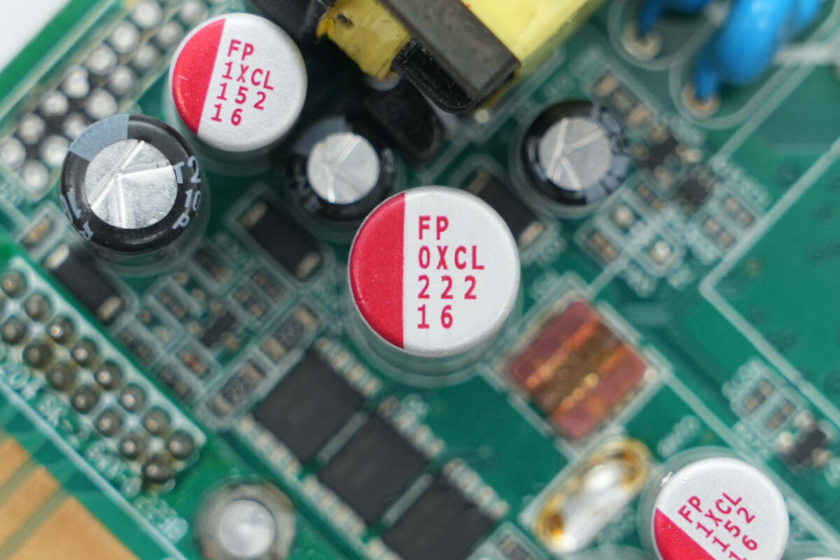
This filter capacitor is rated at 2200μF, 16V.
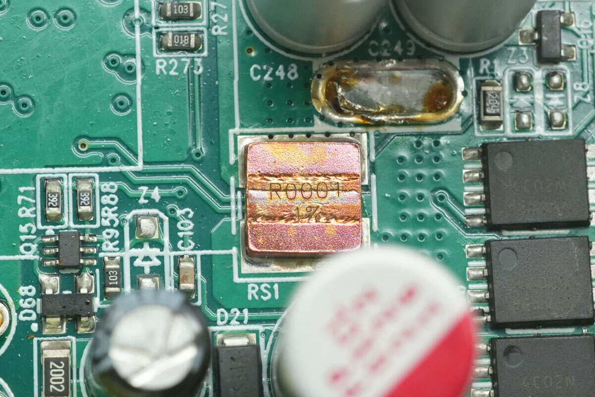
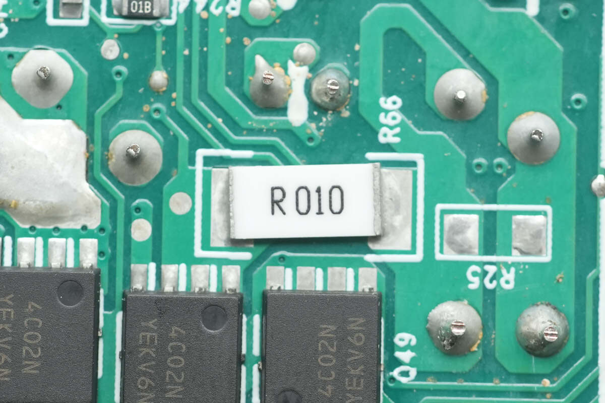
A 0.1mΩ alloy resistor is used for output current sensing.

The SGMICRO SGM8252 Op-Amp is used for current sensing amplification.
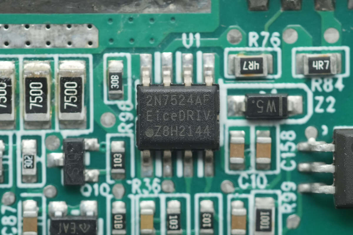
The Infineon 2EDN7524F is used for driving the synchronous rectifiers.
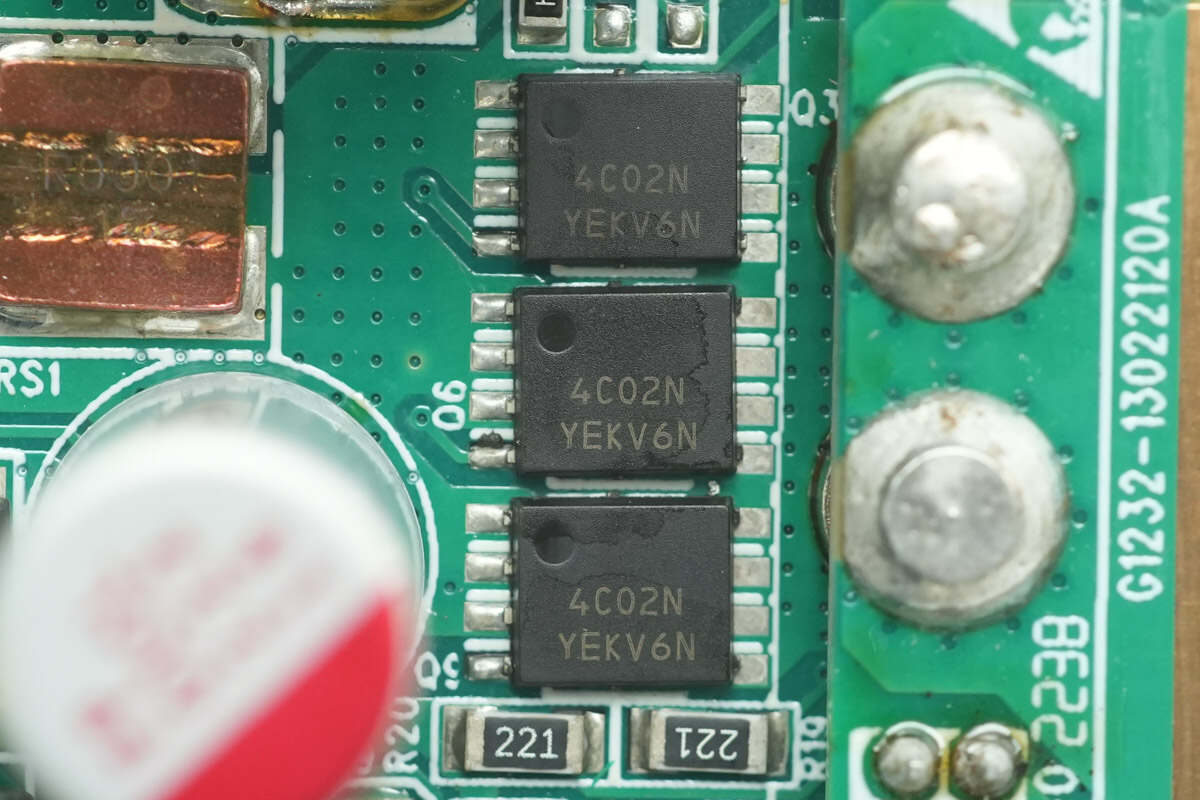
The output MOSFETs are from Onsemi, marked with 4C02N. The model number is NTTFS4C02N. These are NMOS transistors with a voltage rating of 30V and an on-resistance of 1.9mΩ, housed in a WDFN8 package.
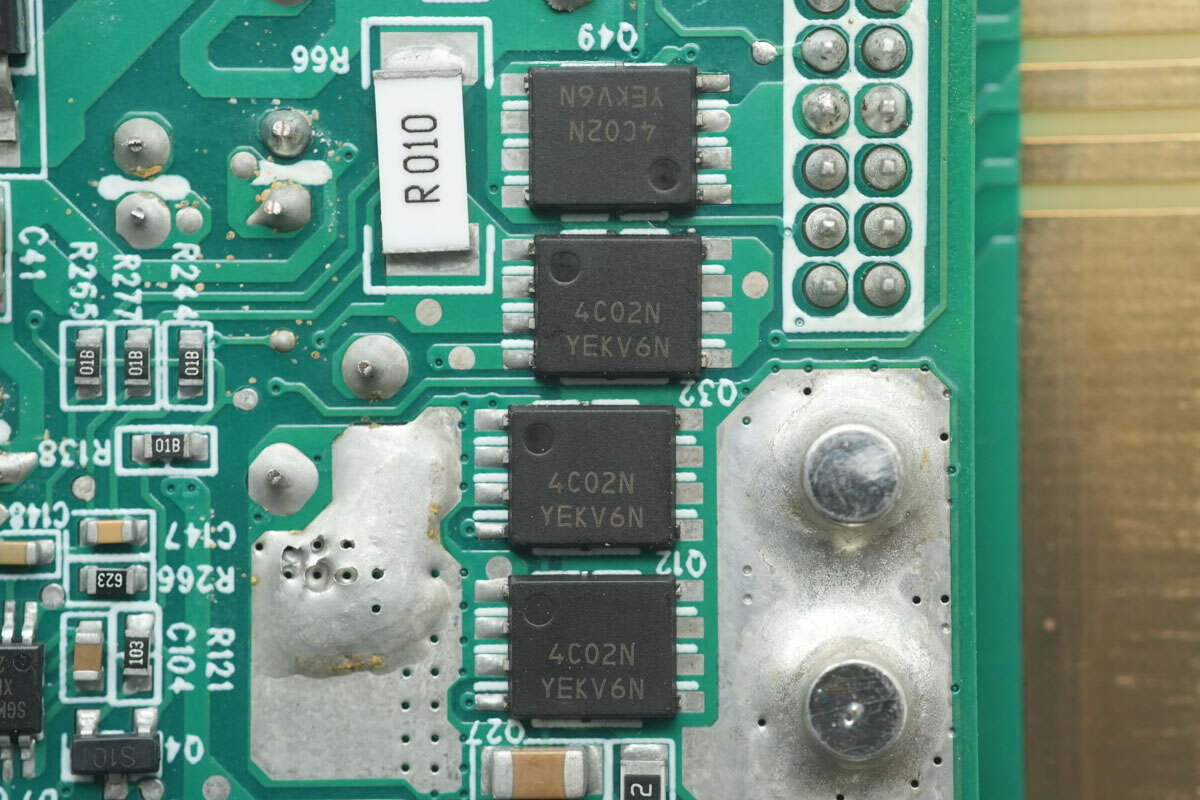
There are four additional control MOSFETs of the same model on the back.
A 10mΩ sensing resistor is used for output current measurement.
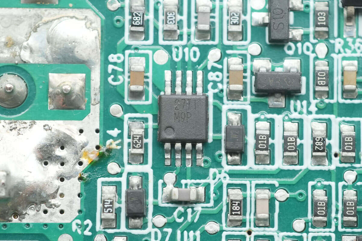
The voltage comparator is from Texas Instruments, marked with M9P. The model is LM393, a dual-channel differential comparator housed in a VSSOP-8 package.
The standby power chip is from On-Bright, model OB2362A. It is a highly integrated current-mode controller featuring adaptive multi-mode operation and low standby power consumption. It comes in a SOT23-6 package.
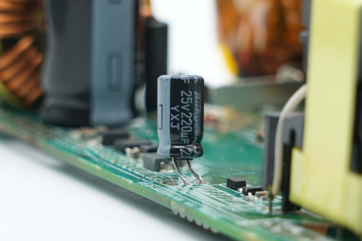
The capacitor supplying power to the master control chip is from Rubycon, rated at 220μF 25V.
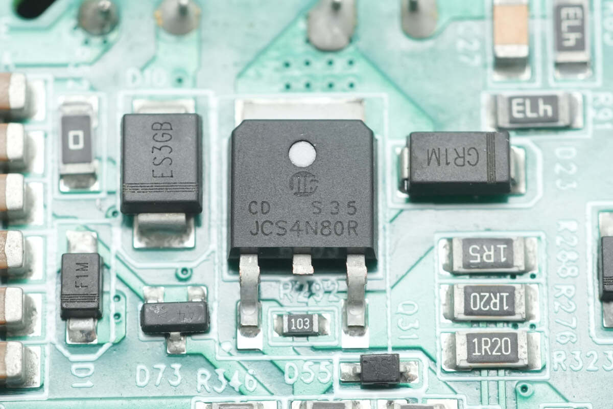
This MOSFET is from HWDZ, model JCS4N80R. It is an NMOS transistor with a voltage rating of 800V and an on-resistance of 2.6Ω, packaged in a DPAK case.
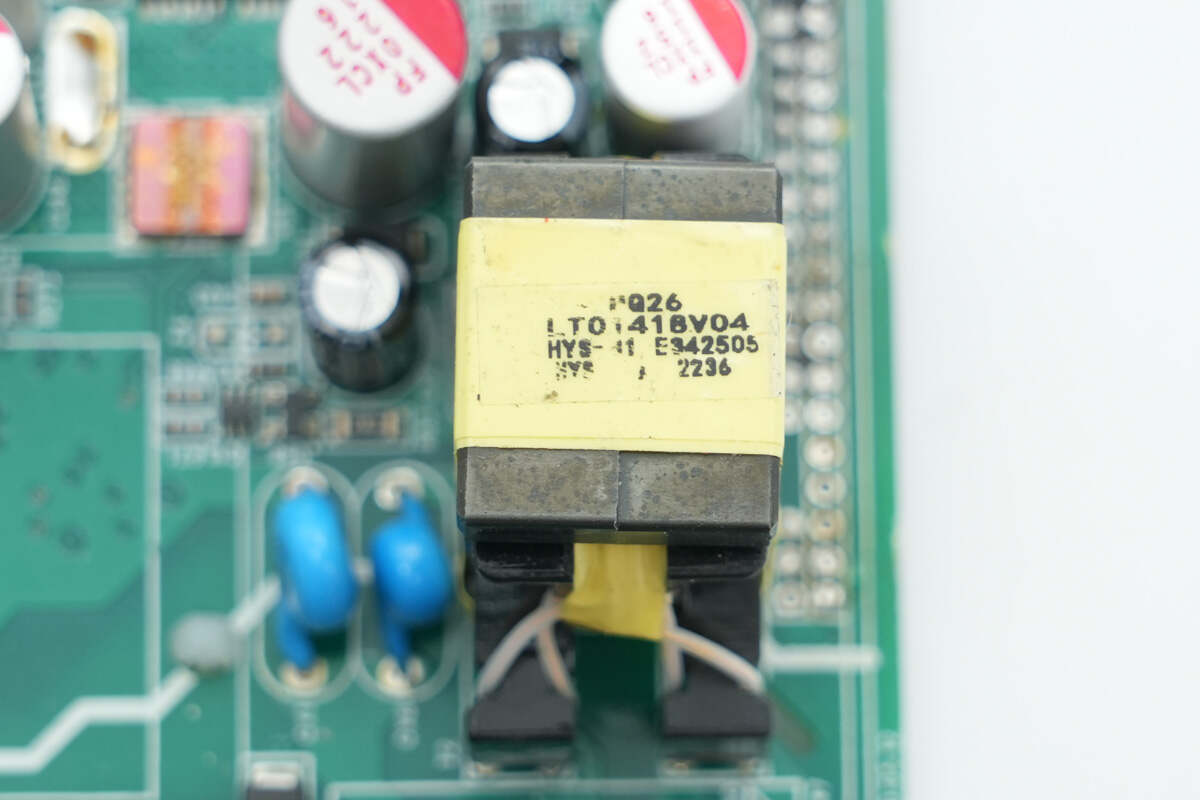
The standby power transformer is wound on a PQ26 magnetic core.
The blue Y-capacitor is manufactured by STE.
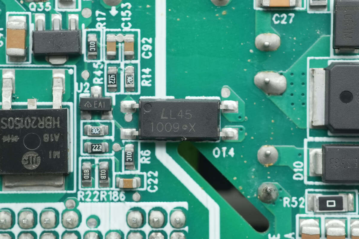
The LITEON LTV1009 optocoupler is used for output voltage feedback.

The Schottky diode is from HWDZ, model HBR20150S, rated at 20A 150V, and packaged in a DPAKM case.
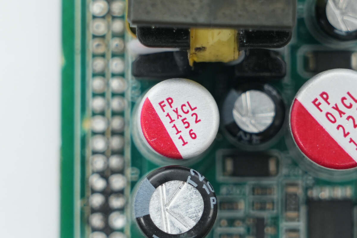
The solid capacitor is rated at 1500μF, 16V.
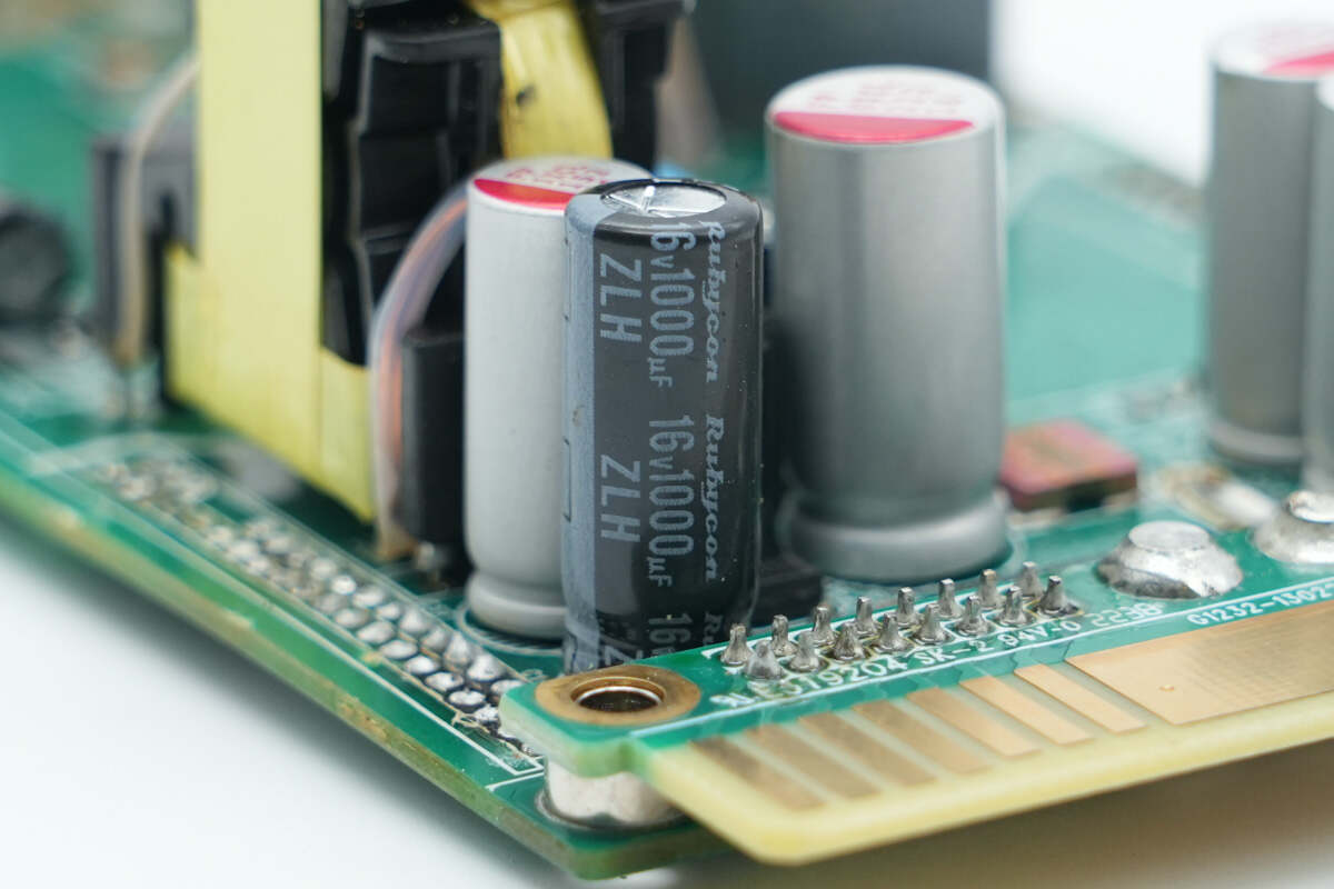
This electrolytic capacitor is rated at 1000μF, 16V.
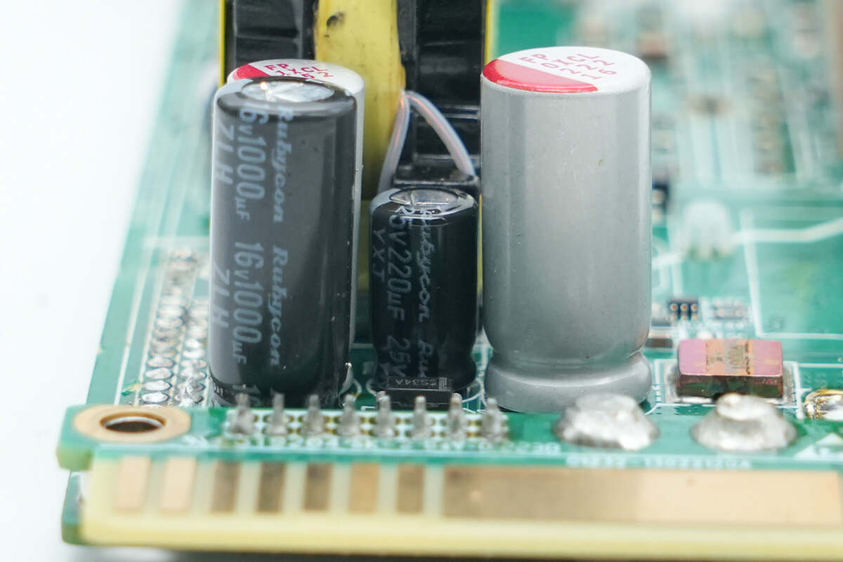
This electrolytic capacitor is rated at 220μF, 25V.
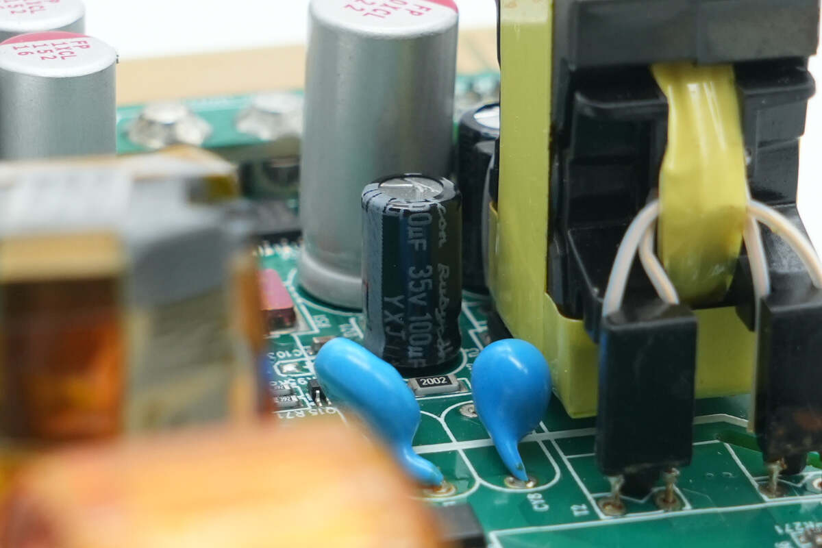
This filter electrolytic capacitor is rated at 100μF, 35V.
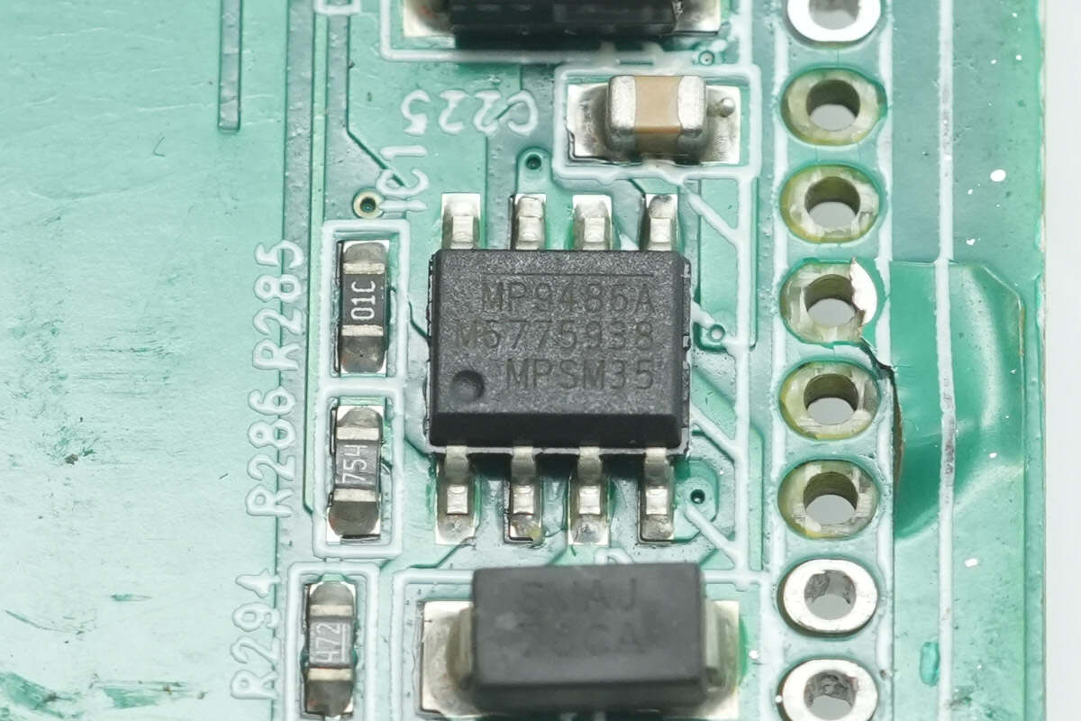
The buck converter chip is from MPS, model MP9486A. It is a switching buck regulator with a wide input voltage range of 4.5–100V, supporting a 1A output current. It features over-temperature and short-circuit protection and comes in an SOIC-8 EP package.
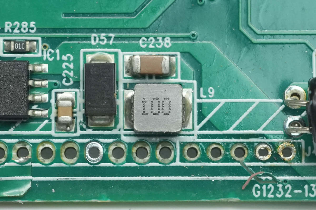
Close-up view of the 10μH alloy inductor.
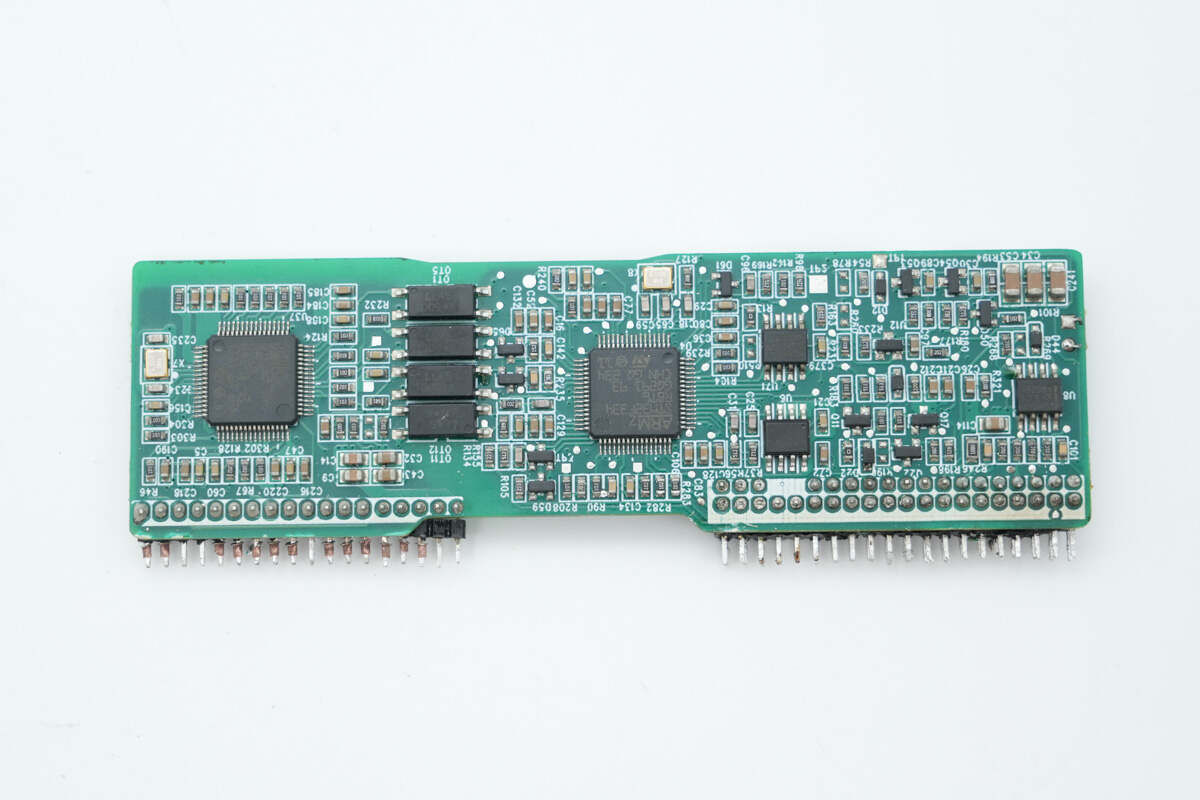
The control PCB includes a boost controller, an LLC controller, feedback optocouplers, memory devices, and an Op-Amp.
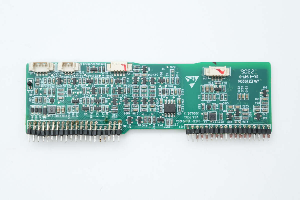
On the backside, there are Op-Amps, a buck converter chip, and a thermistor.

The boost controller is from STMicroelectronics, model STM32F334R8T6. It features a 32-bit ARM Cortex-M4 CPU with an FPU, operating at up to 72 MHz. It includes 64 KB of Flash memory, 12 KB of SRAM with parity support, two fast 12-bit ADCs, ultra-fast comparators, and supports six-channel PWM signal output. It is housed in an LQFP64 package.
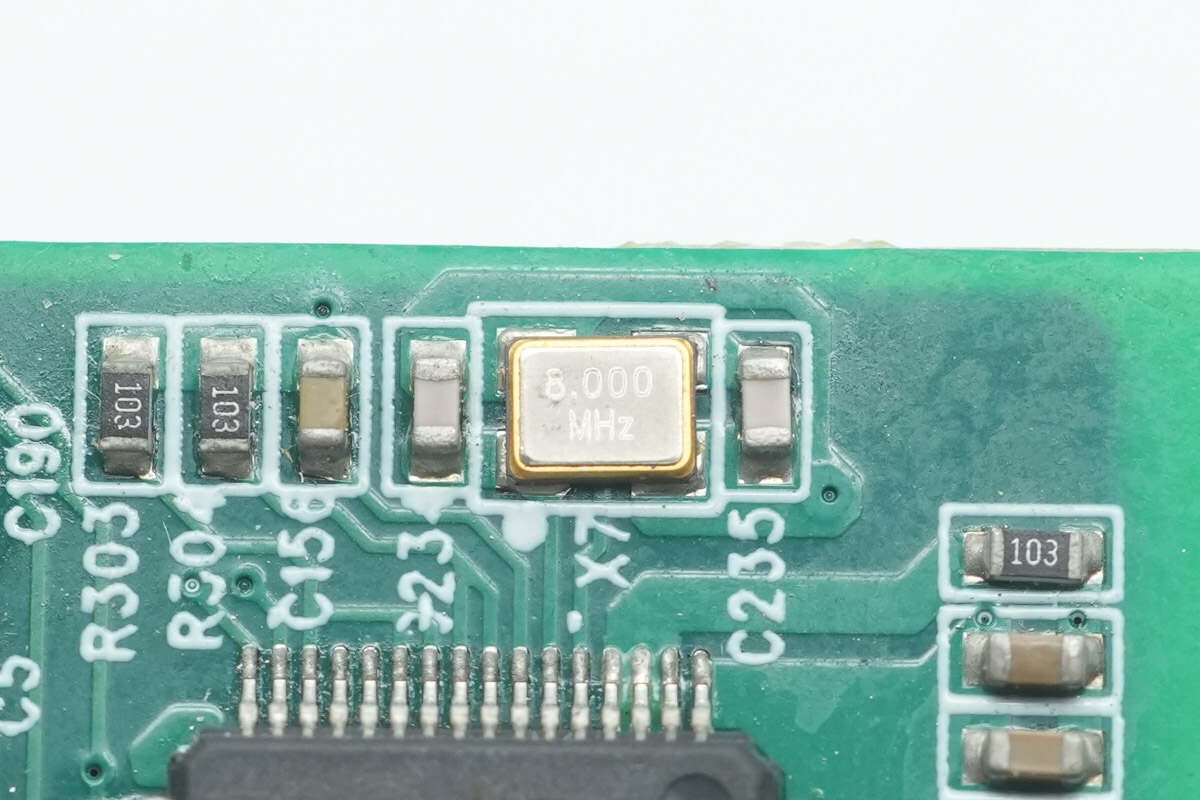
Close-up of the 8.000 MHz crystal oscillator.
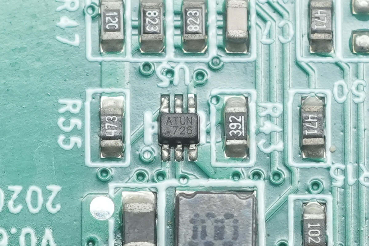
The buck converter chip is from MPS, marked with ATU, model MP1652. It is a synchronous buck regulator with an input voltage range of 4.2–18V and supports an output current of up to 2A. The device integrates internal MOSFETs, features fast transient response, operates at a switching frequency of 680 kHz, and includes overcurrent protection and thermal shutdown. It is packaged in a SOT563 case.
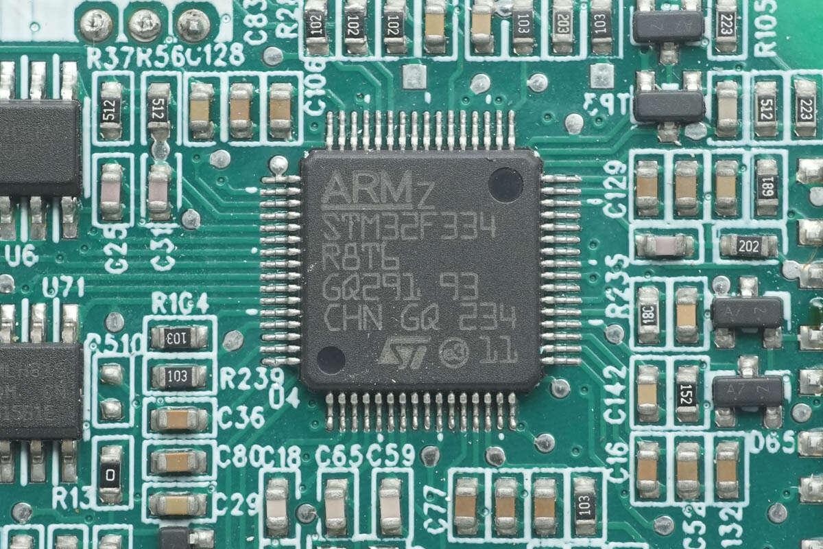
The LLC controller also uses the STMicroelectronics STM32F334R8T6.
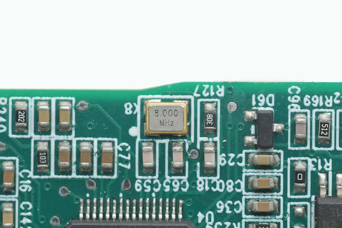
The chip is paired with an external 8.000 MHz crystal oscillator.
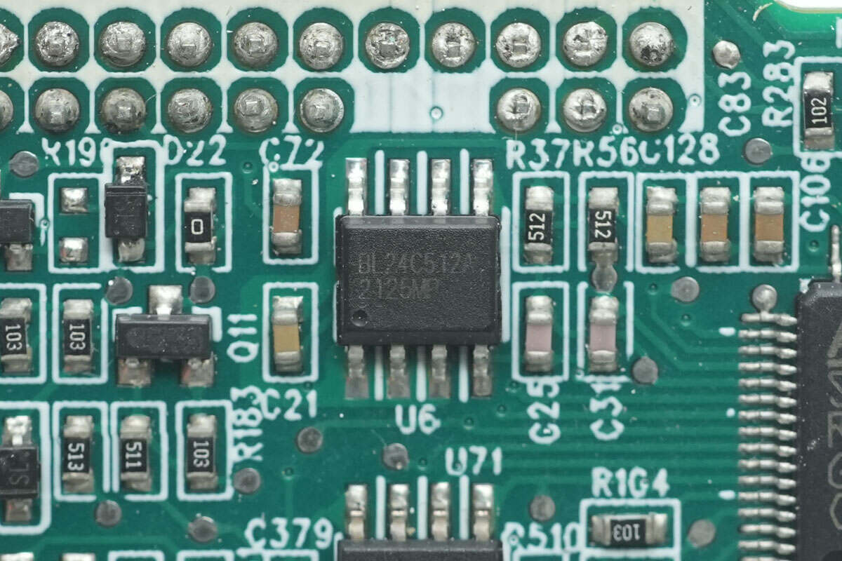
The memory chip is from Belling, model BL24C512A. It has a capacity of 64KB and is housed in an SOP-8 package.
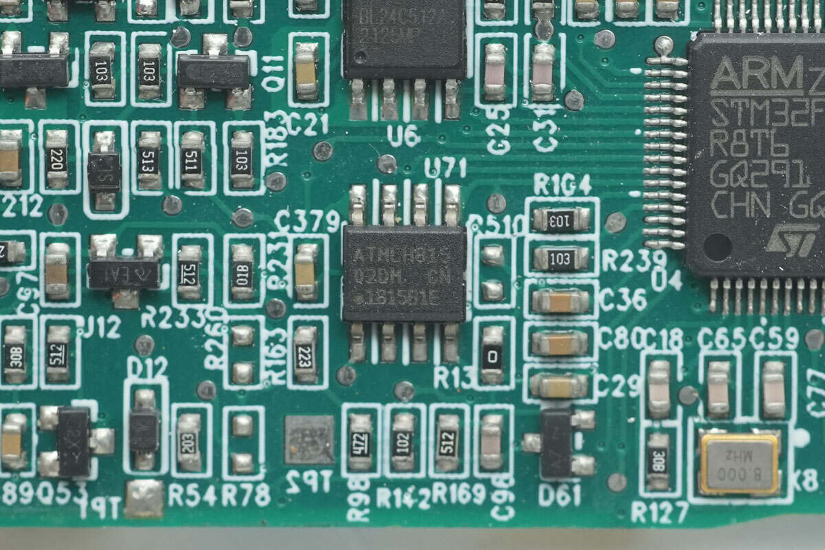
The memory chip is from Microchip, marked with 02DM, model AT24C02D. It supports an operating voltage range of 1.7–3.6V and is housed in an SOIC-8 package.
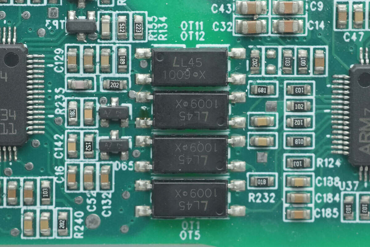
LITEON LTV1009 optocouplers are used for isolated communication between MCUs.
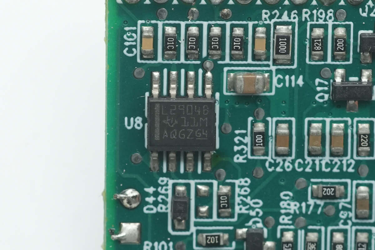
The Op-Amp is from Texas Instruments, model LM2904B. It is an industry-standard dual op-amp, packaged in an SOIC-8 case.
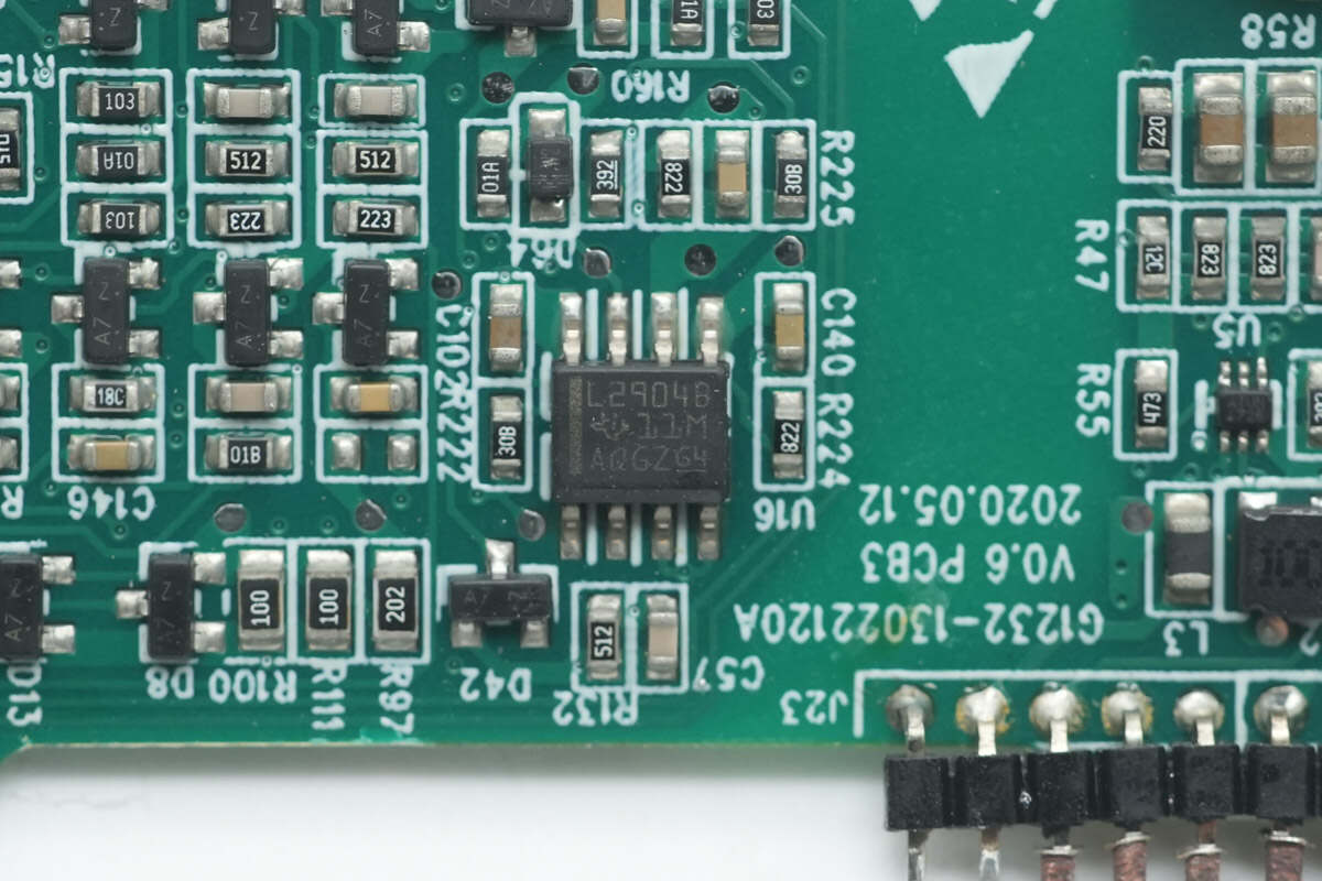
The other Op-Amp has the same model number.
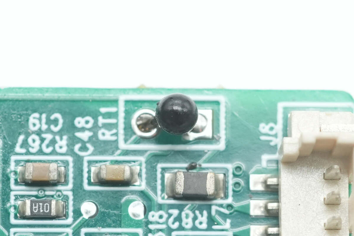
The thermistor is used for monitoring the intake temperature.
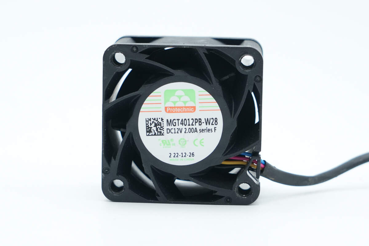
The cooling fan is from PROTECHNIC, model MGT4012PB-W28, rated at 12V 2A, manufactured in China.
Well, those are all components of the Gospower 1300W DC Server Power Supply.
Summary of ChargerLAB
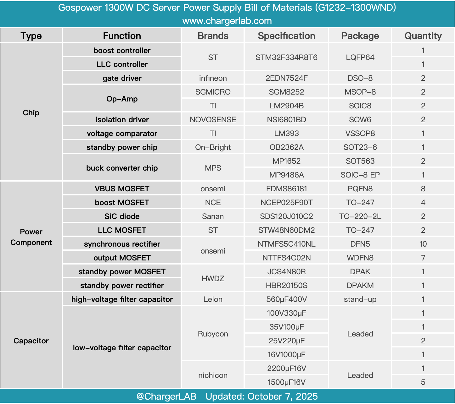
Here is the component list of the Gospower 1300W DC Server Power Supply for your convenience.
It belongs to the LVDC series, supporting a -48V battery pack input. The rated output voltage is 12V with an output current of 108A. The standby power output voltage is 12V with a rated current of 2.1A. An internal cooling fan draws air in from the output side and exhausts it through the input side. The input features a DC power socket with reverse polarity protection.
After taking it apart, we found that it adopts two STMicro STM32F334R8T6 MCUs used for both boost and LLC control. The boost MOSFETs are NCE NCEP025F90T, driven by Infineon 2EDN7524F driver, and use Sanan SDS120J010C2 SiC diodes for rectification. The LLC MOSFETs are STMicro STW48N60DM2, driven by NOVOSENSE NSi6801BD isolated drivers.
The synchronous rectifiers use Onsemi NTMFS5C410NL, driven by Infineon 2EDN7524F. The standby power chip is an On-Bright OB2362A, with both MOSFET and rectifier sourced from HWDZ. The high-voltage filter capacitor is from Lelon, while low-voltage filter capacitors come from Rubycon and Nichicon. The power supply employs multiple small PCBs vertically soldered together to optimize space utilization, demonstrating solid build quality and reliable component selection.
Related Articles:
1. Teardown of Xiaomi 17 Pro Retro Handheld Console Case (25099TC43C)
2. Teardown of Huawei SuperPower 100W 12000mAh Power Bank (P0020)
3. Teardown of EcoFlow RAPID Pro 230W 20,000mAh Power Bank with Built-in Cable (EF-HB-100)