Introduction
In this issue, we will be tearing down a 1725W switching power supply module from Emerson. This power module provides a 12.3V output and supports a wide input voltage range of 100–240V. When the input voltage is between 100–127VAC, it delivers 950W of output power. At 200VDC input, the output reaches 1400W, and at 200–240VAC input, it achieves the rated output power of 1725W.
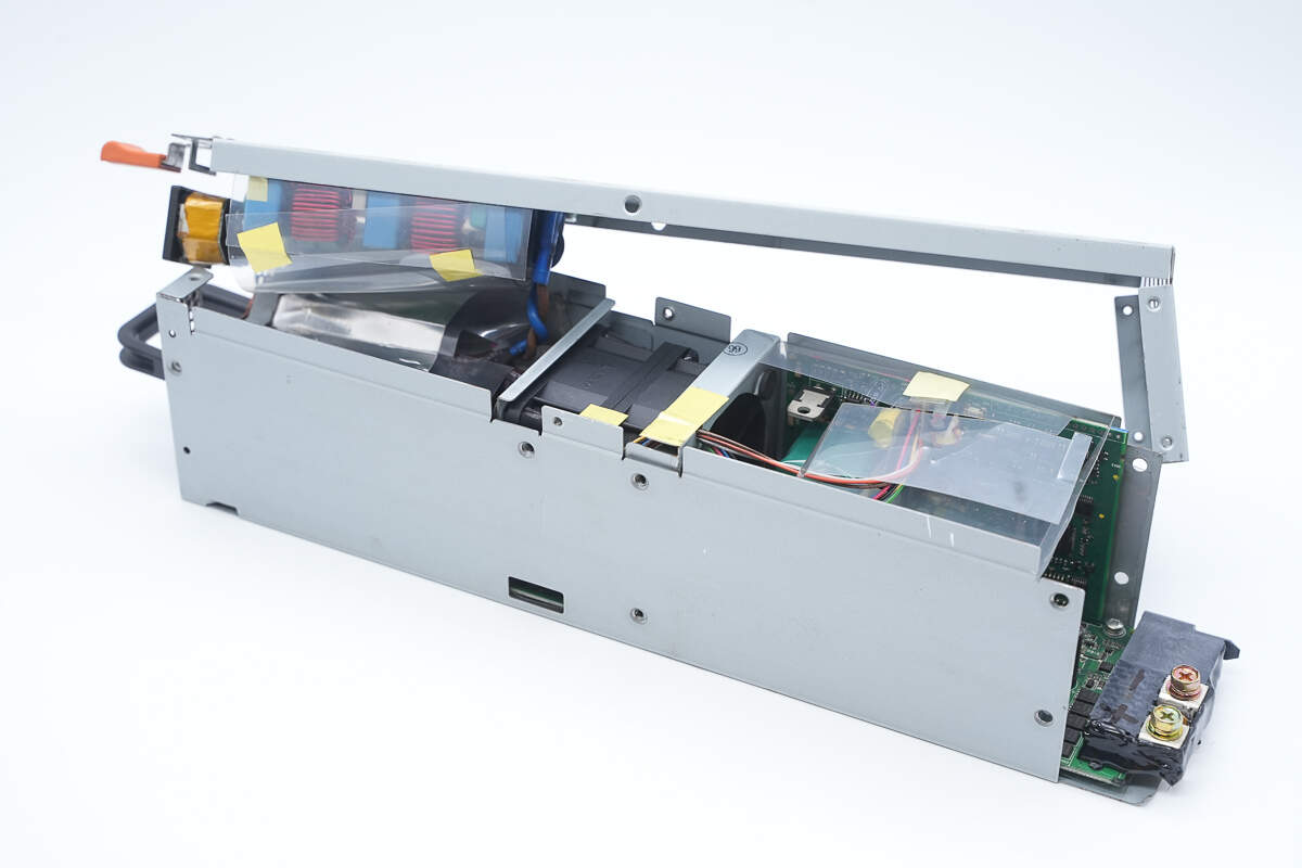
The power supply features a long metal enclosure with an internal cooling fan. The input side includes a handle, indicator lights, and a C14 AC inlet. The output side is equipped with a power connector and utilizes a PFC + forward converter architecture. Now, we will take you through the teardown to explore its internal design and components.
Product Appearance
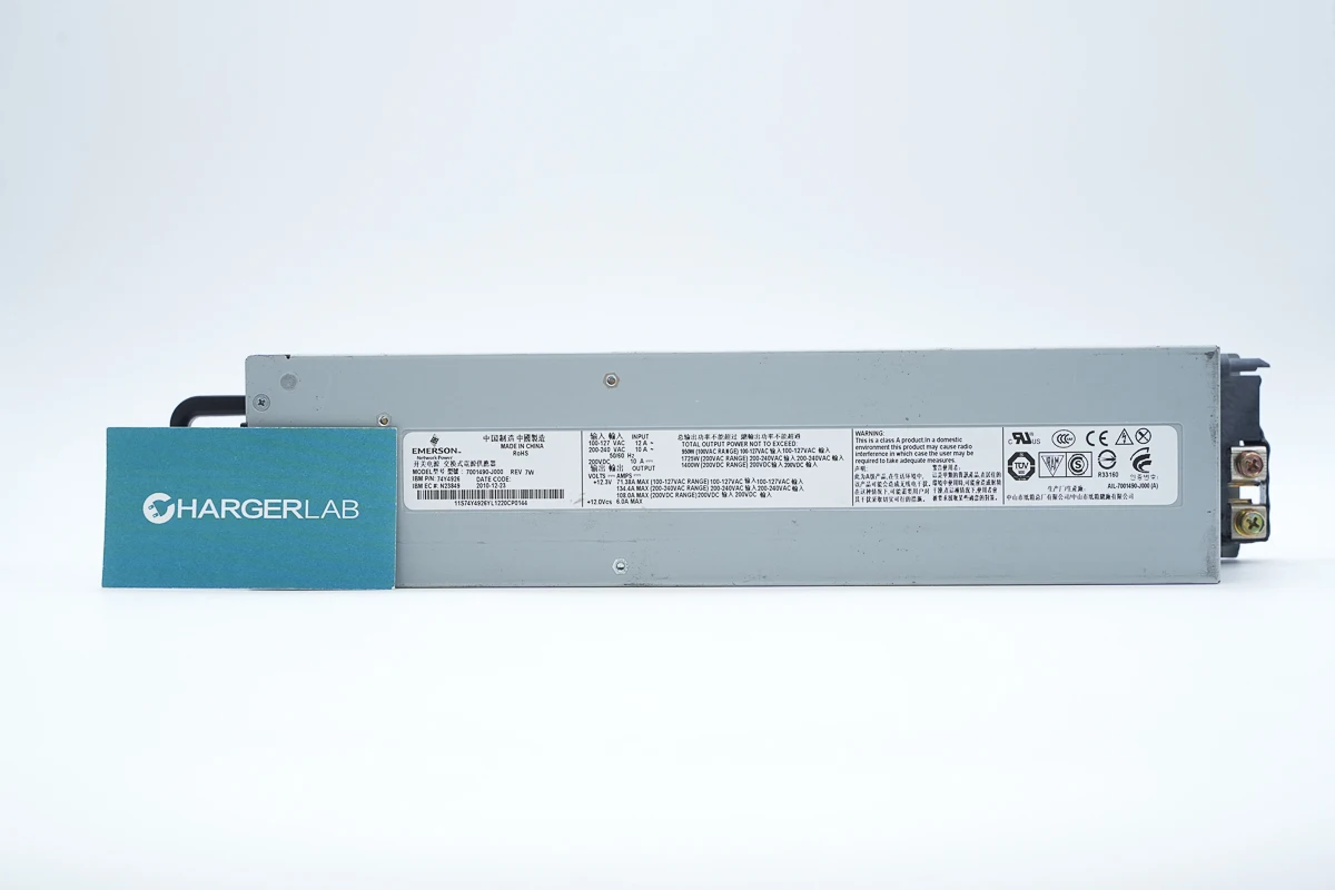
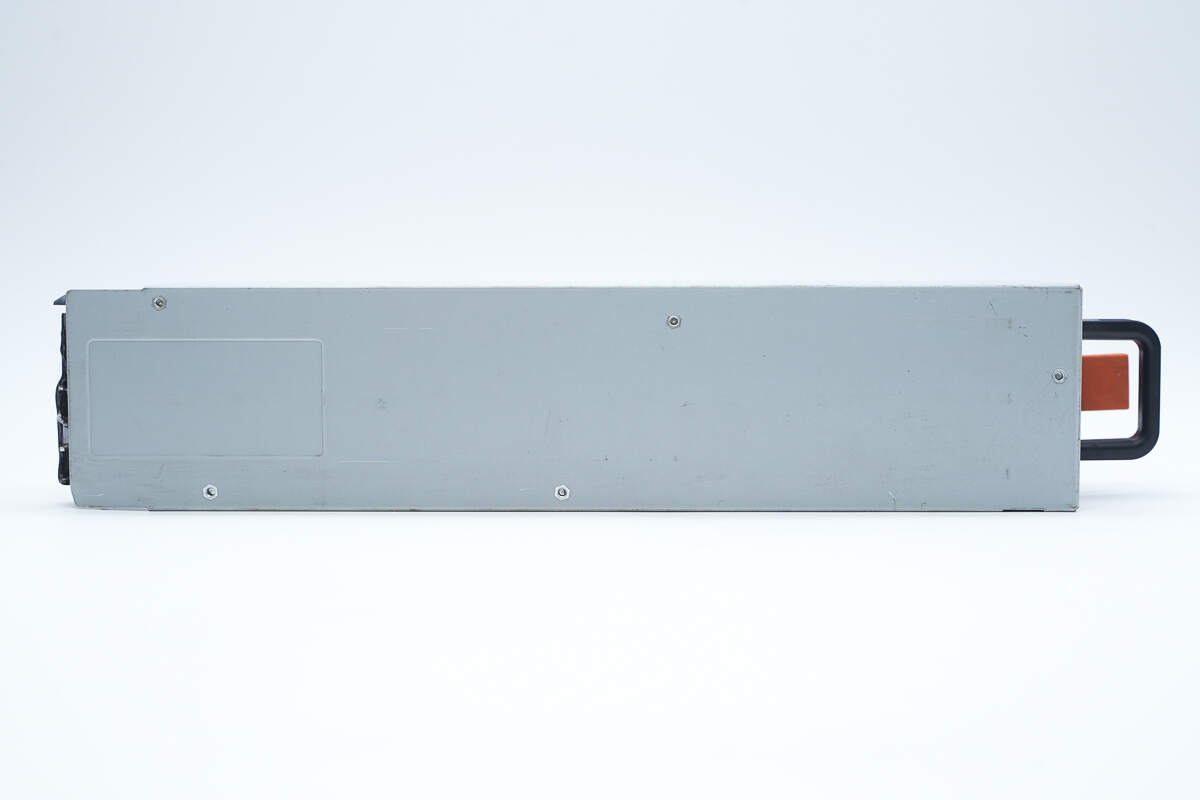
The power module features a long, rectangular metal enclosure.
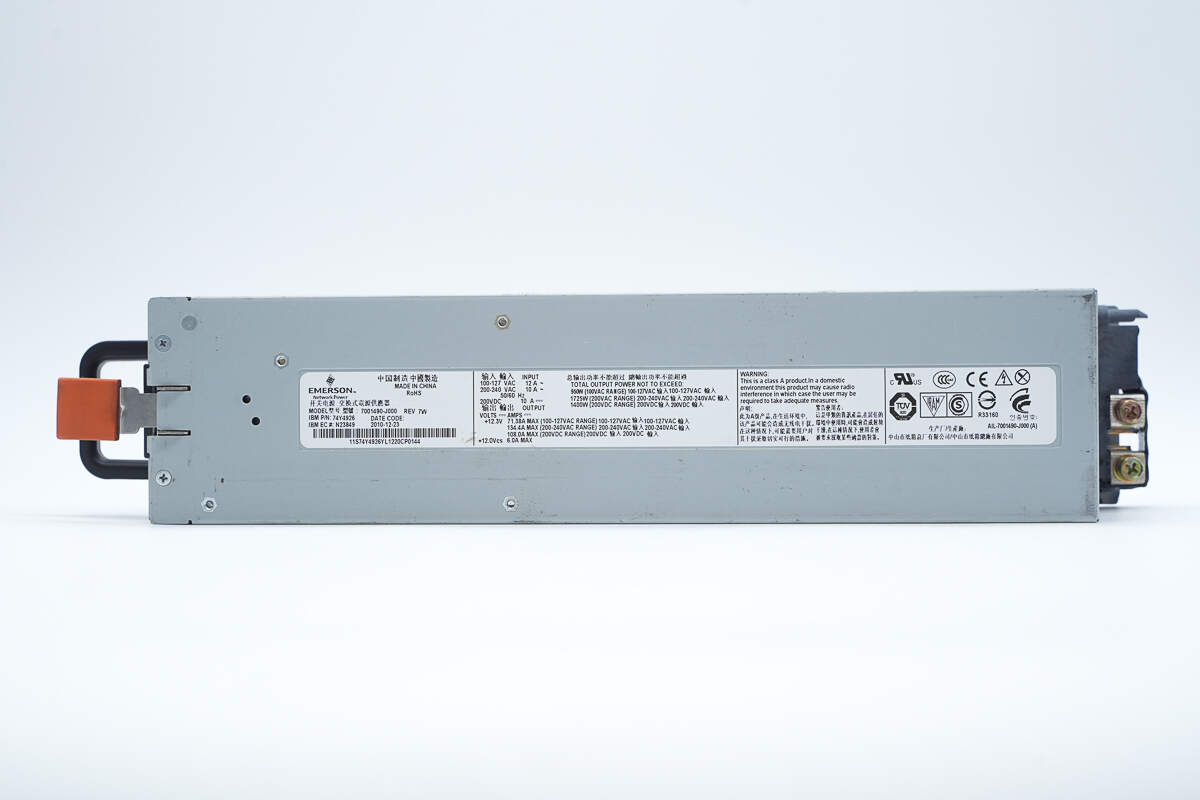
An information label is affixed to the metal enclosure.
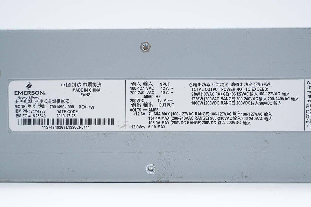
Model: 7001490-J000
Input: 100–127VAC 12A\~
200–240VAC 10A\~
50/60Hz
200VDC 10A
Output:
+12.3V 71.38A MAX (100–127VAC input)
134.4A MAX (200–240VAC input)
108A MAX (200VDC input)
+12Vcs 6A MAX
Total output power not to exceed:
950W (100–127VAC input)
1725W (200–240VAC input)
1400W (200VDC input)
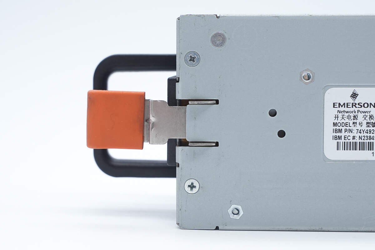
Close-up of the fixed handle.
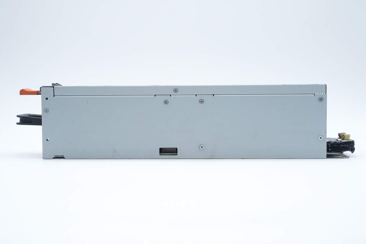
The side is equipped with mounting screws.
The bottom features nuts used to secure the internal PCBA module.
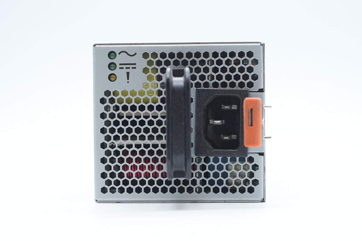
The input side includes indicator lights, a handle, a C14 power inlet, and a release lever.
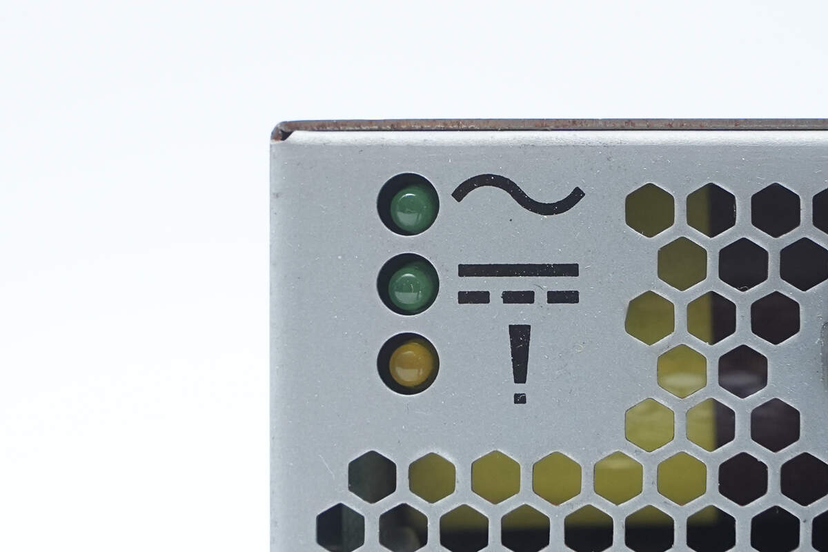
The indicator lights are used to show AC input status, DC output status, and power fault conditions.
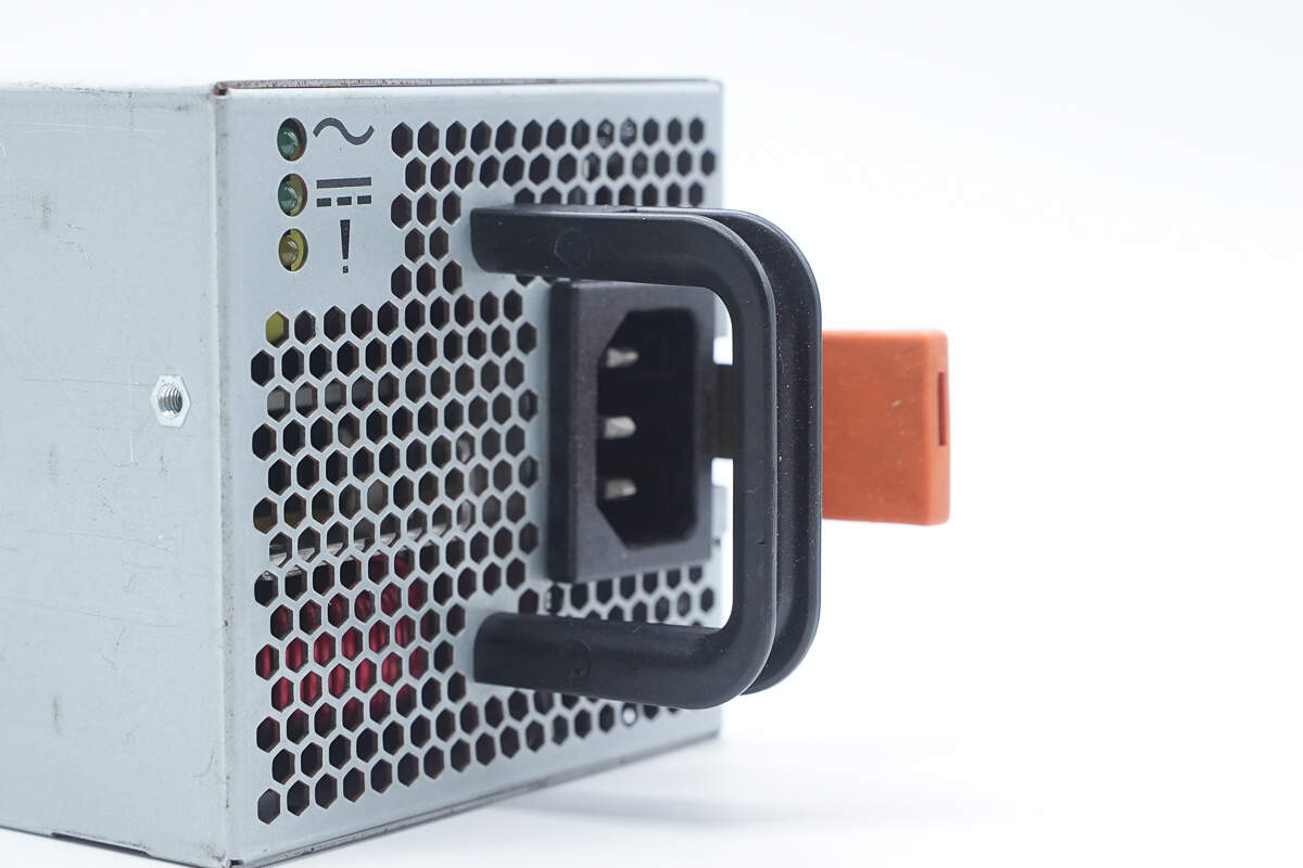
Close-up of the handle.
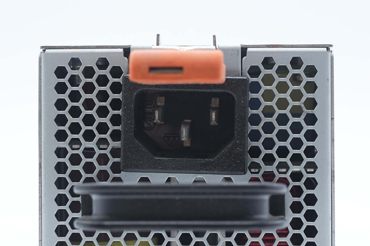
Close-up of the C14 power inlet.
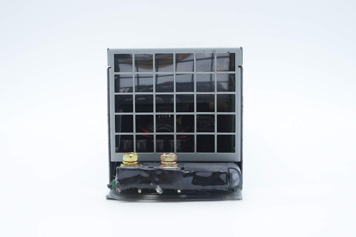
The output side features terminals and a cooling grille.
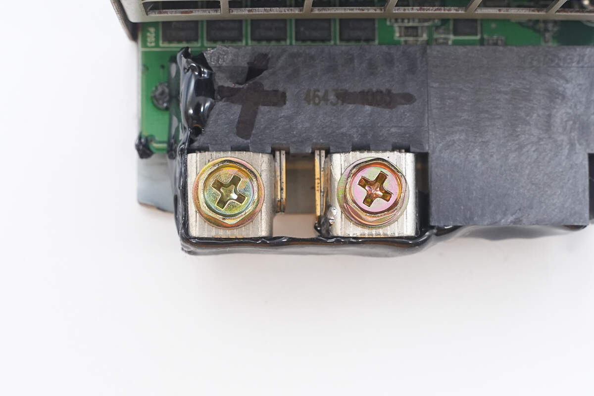
Close-up of the terminals on the output side.
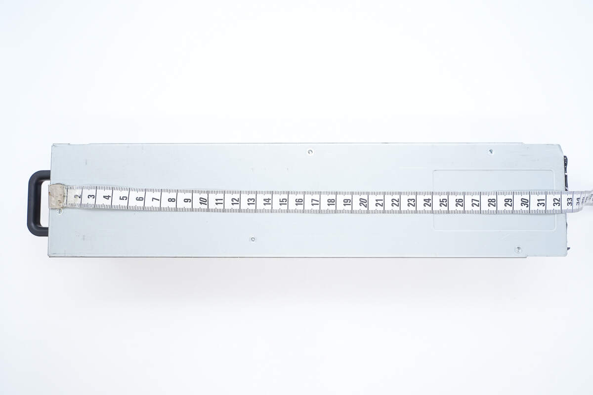
The length is about 324 mm (12.76 inches).
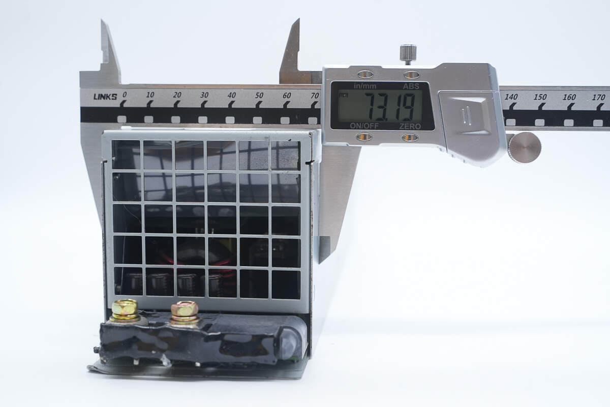
The width is about 73.2 mm (2.88 inches).
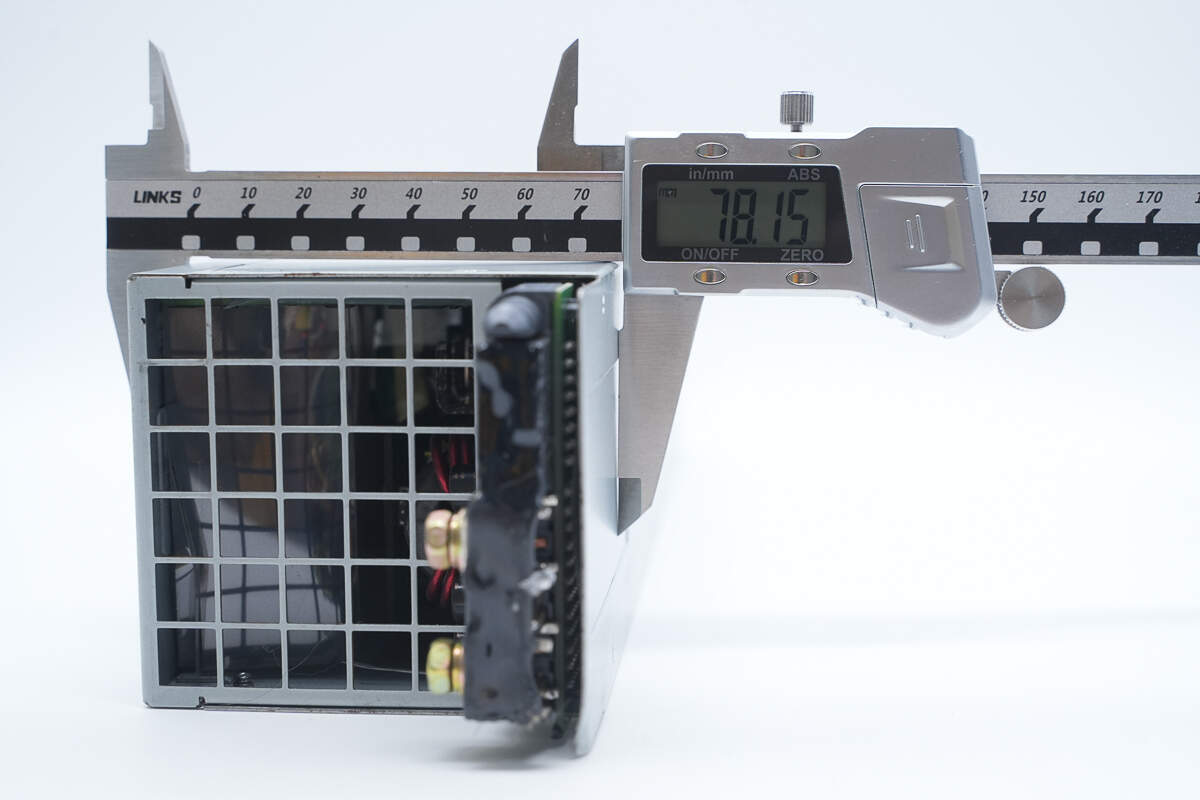
The thickness is about 78.2 mm (3.079 inches).
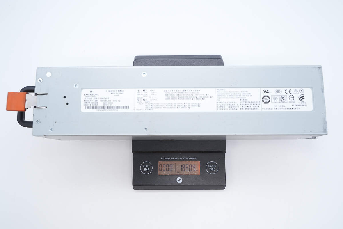
The weight is about 1861 g (65.64 oz).
Teardown
Next, let's take it apart to see its internal components and structure.
First, unscrew the mounting screws to remove the top cover.
Inside the top cover, there is a PCB secured by screws and connected via plug-in connectors.
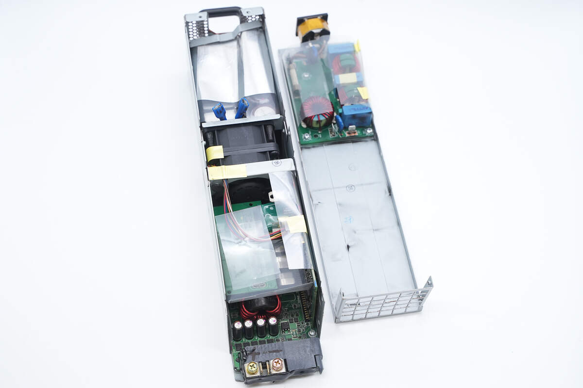
Disconnect the plug-in connectors to separate the top cover.
The PCB inside the top cover is wrapped with a Mylar sheet for insulation.
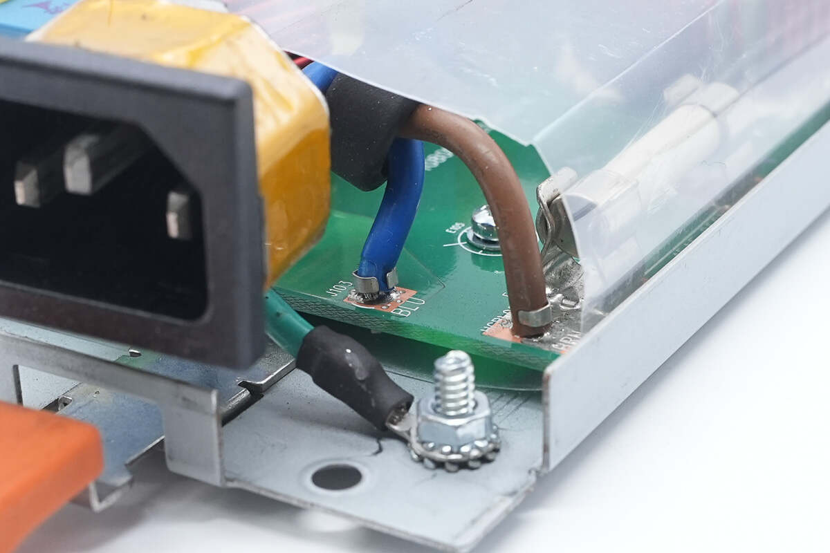
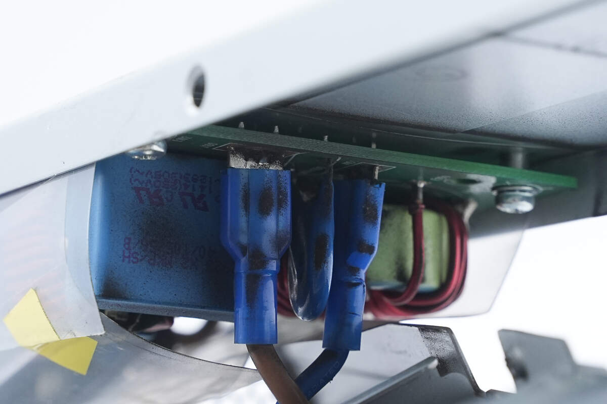
The power wires are soldered to cold-pressed terminals, and the ground wire is secured with a screw.

The C14 power inlet is encased in a metal housing.
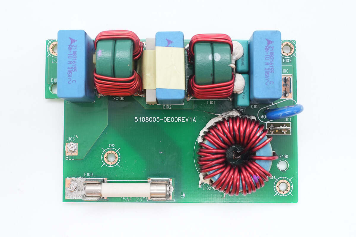
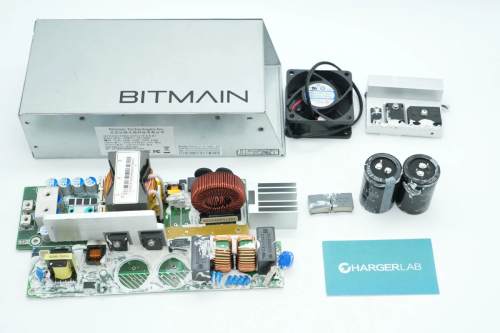
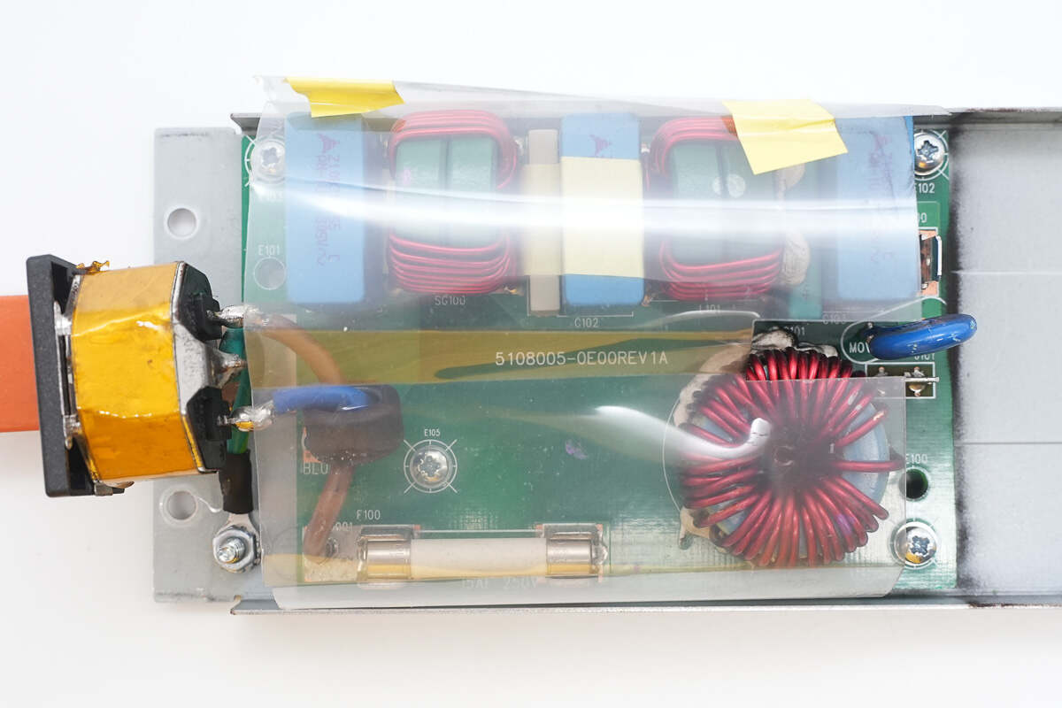
Remove the input filter PCB. Below is a fuse and a filter inductor. Above are safety X2 capacitors, common mode chokes, and safety Y capacitors.
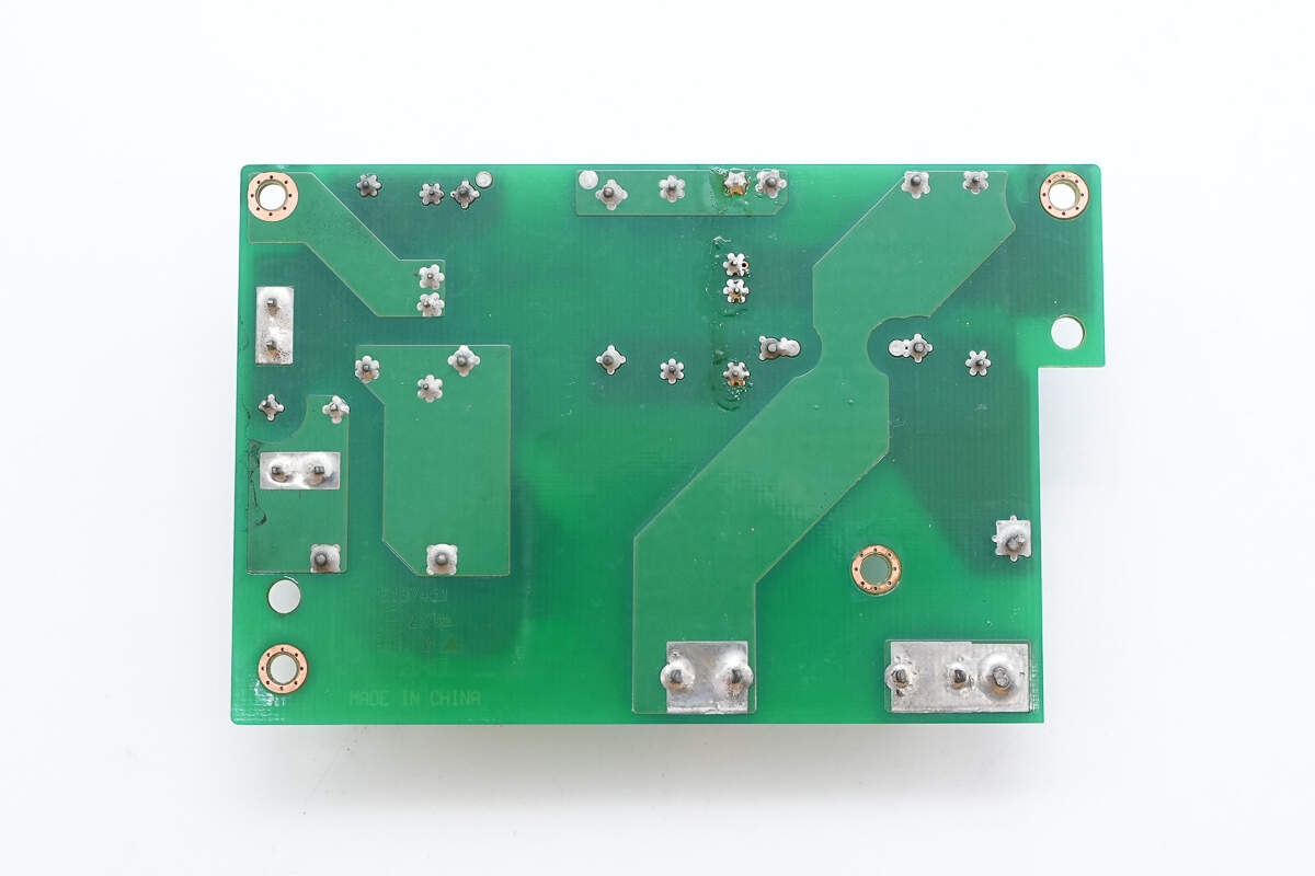
There are no components on the back.
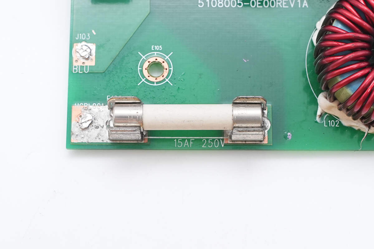
The fuse is rated at 15A, 250V.

There are three safety X2 capacitors, two stages of common mode chokes, and four safety Y capacitors.
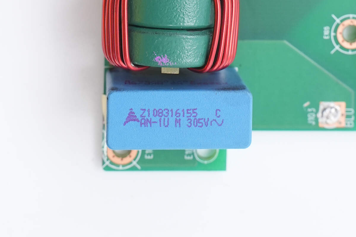
The safety X2 capacitors are from TDK, with a specification of 1μF.
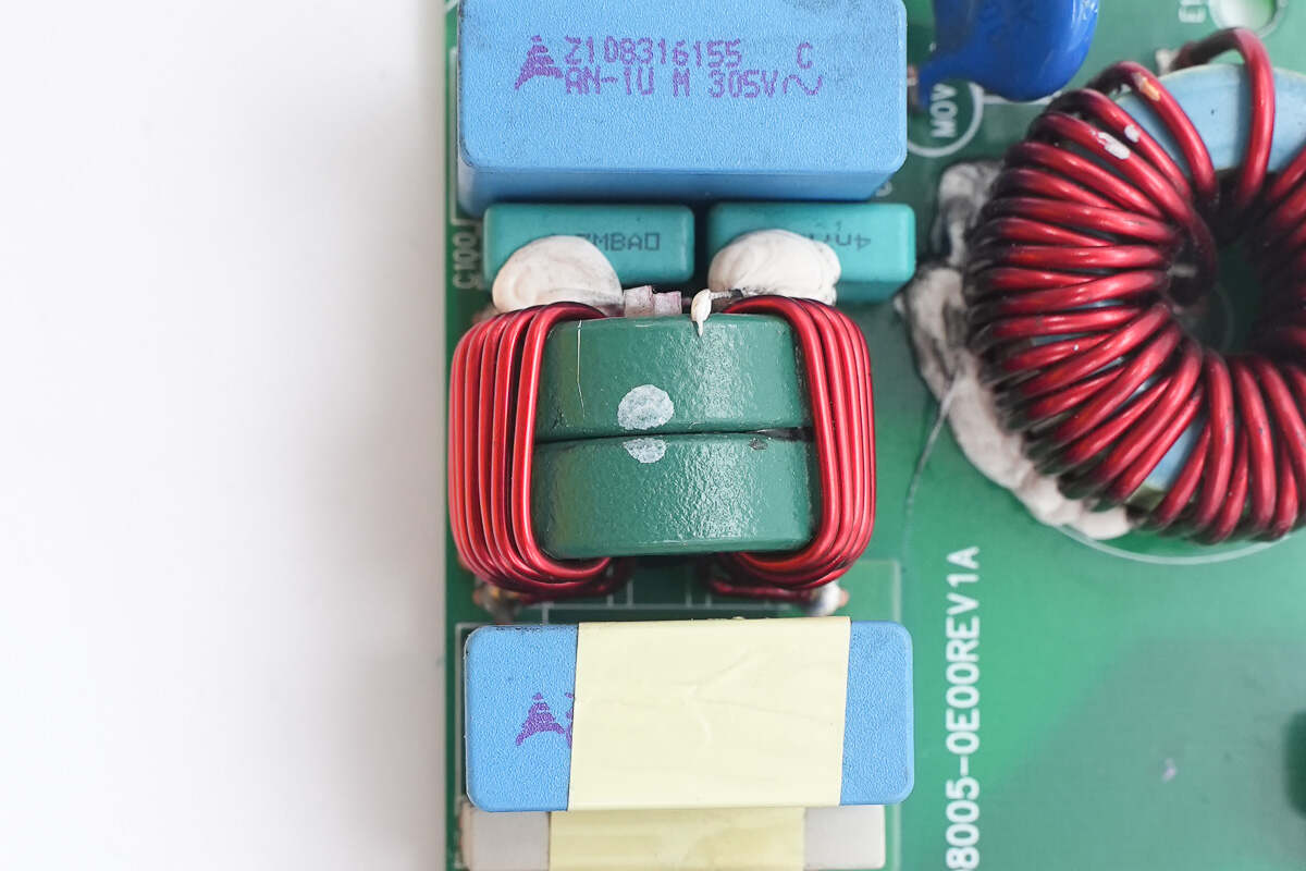
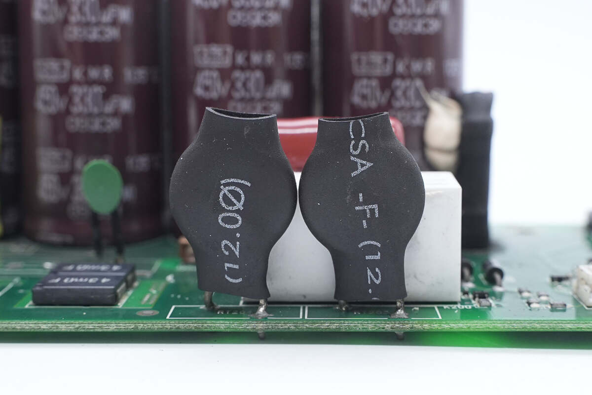
The common mode choke uses a toroidal winding and is insulated internally with a Bakelite board.
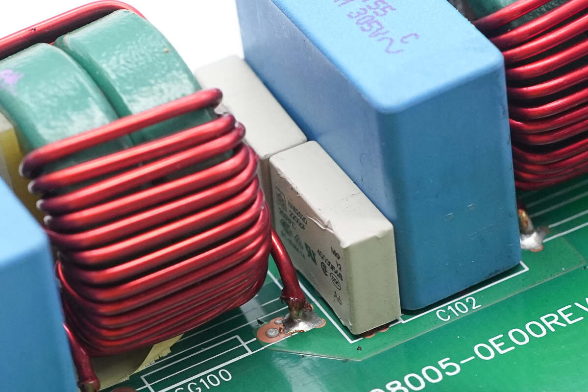
The white film Y capacitors are from EKOVA, with a capacitance of 2200pF.
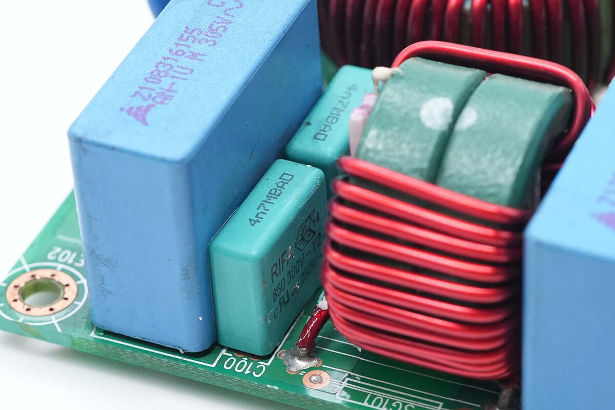
The blue-green film Y capacitors are from RIFA, with a capacitance of 4.7nF.
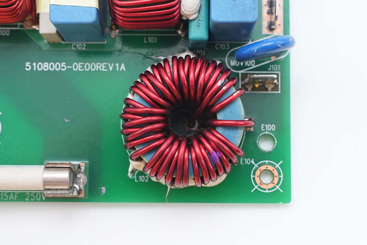
The filter inductors use toroidal winding construction.
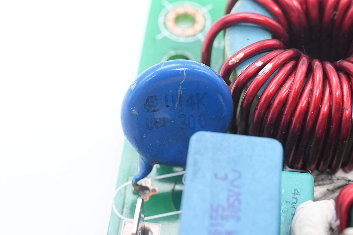
The blue varistor is used for output overvoltage protection.
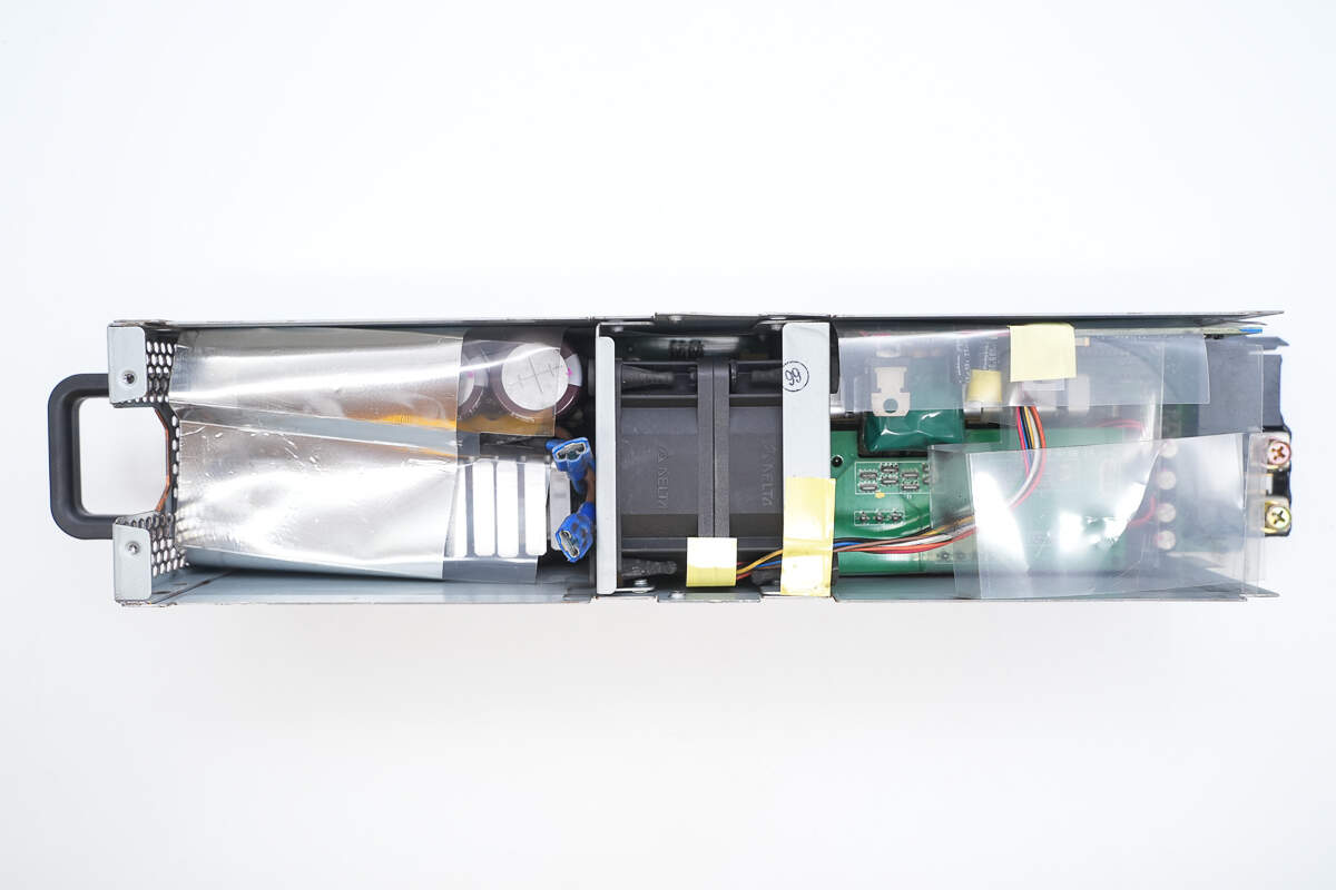
The other part of the enclosure is divided into two sections by a fan.
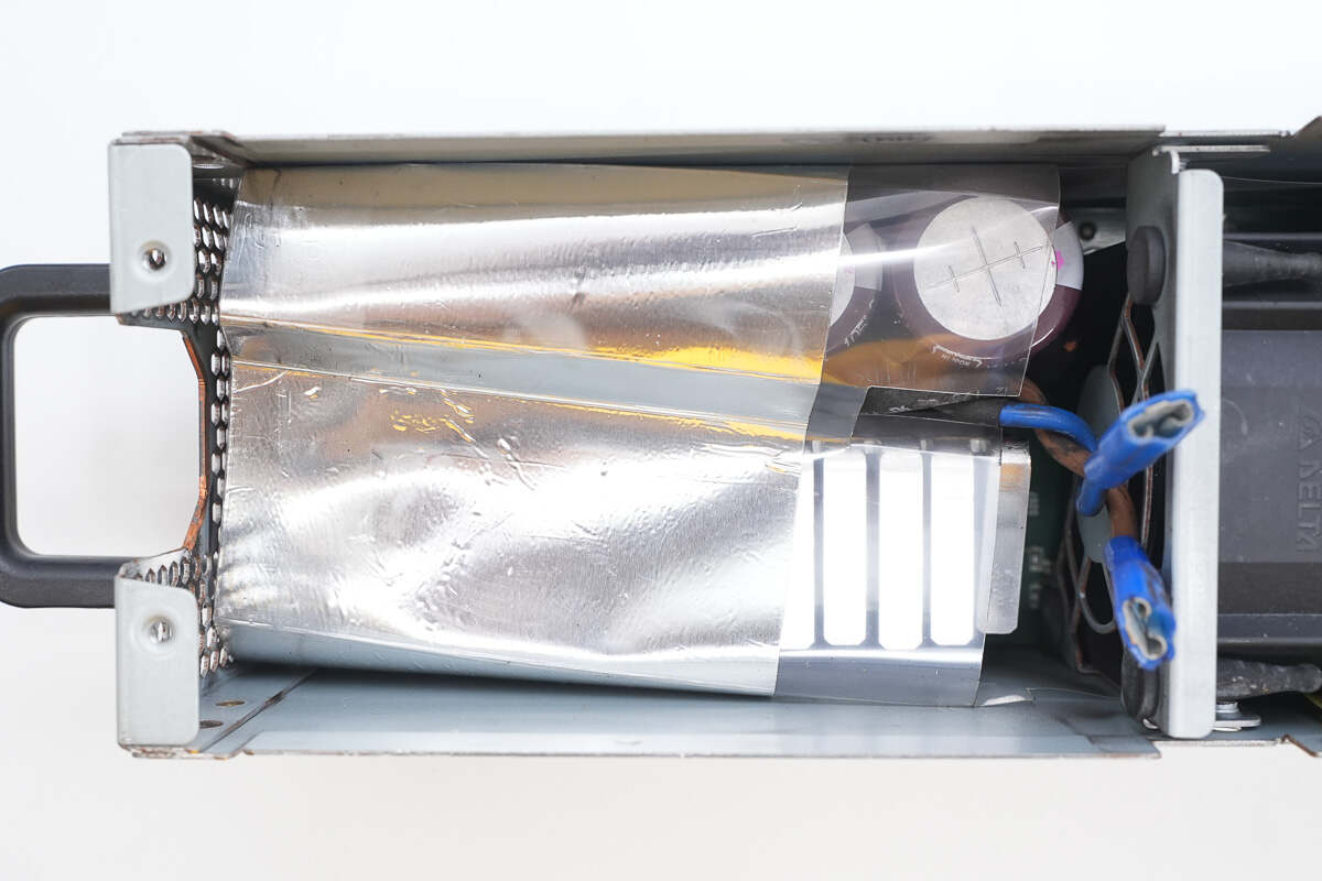
The left side houses the PFC circuit, which is insulated with a Mylar sheet and shielded with aluminum foil.
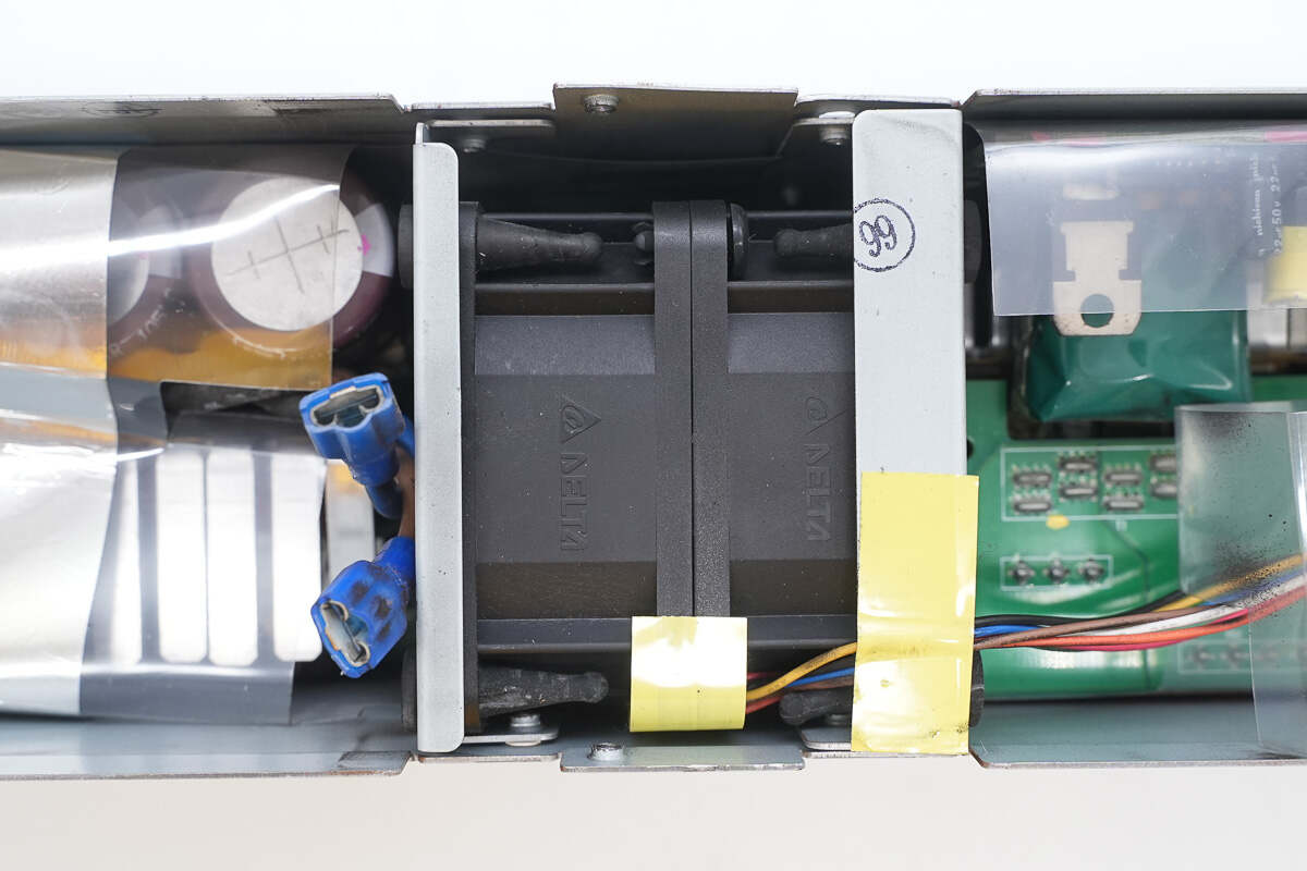
The cooling fan is secured in the middle by a metal frame.
The Mylar sheet directs airflow to pass over the transformer.
The cooling fan is connected to the control PCB.
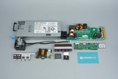
Unscrew the screws and remove the PCBA module.
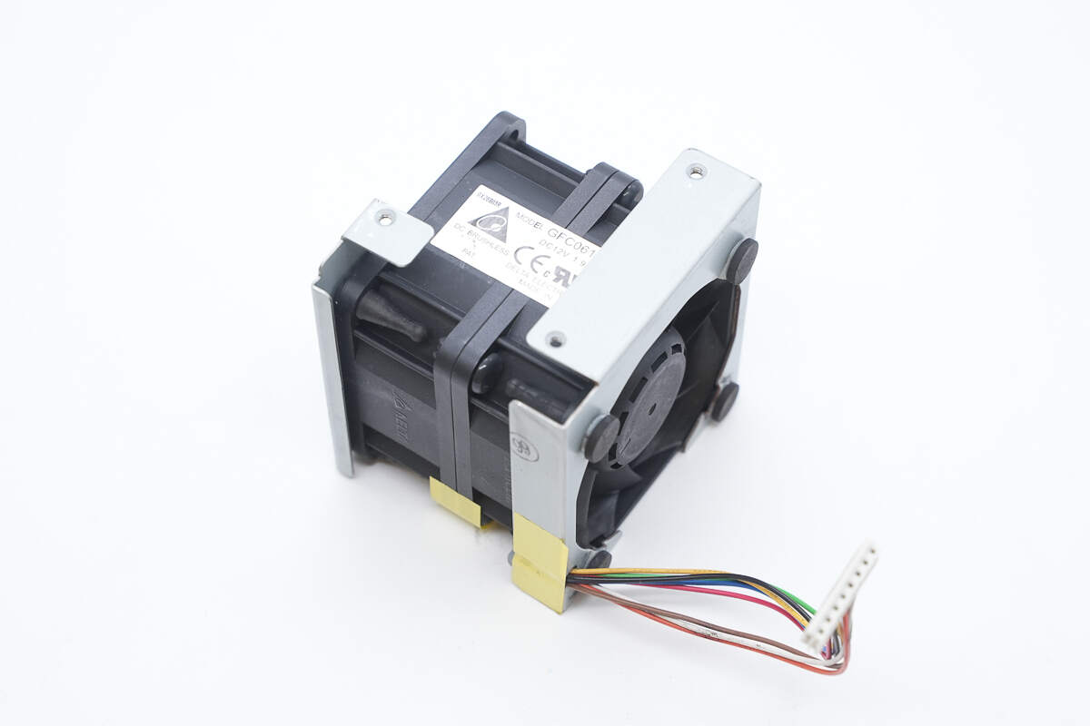
The cooling fan is secured by a metal frame.
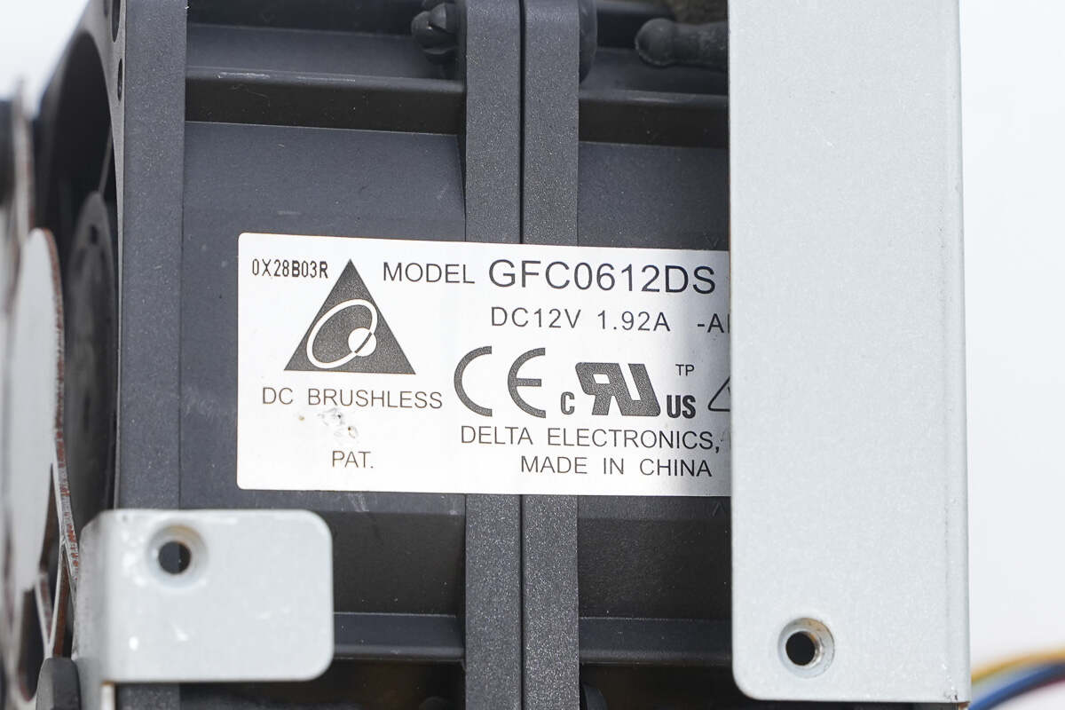
The fan is from Delta, model GFC0612DS, rated at 12V 1.92A, made in China.
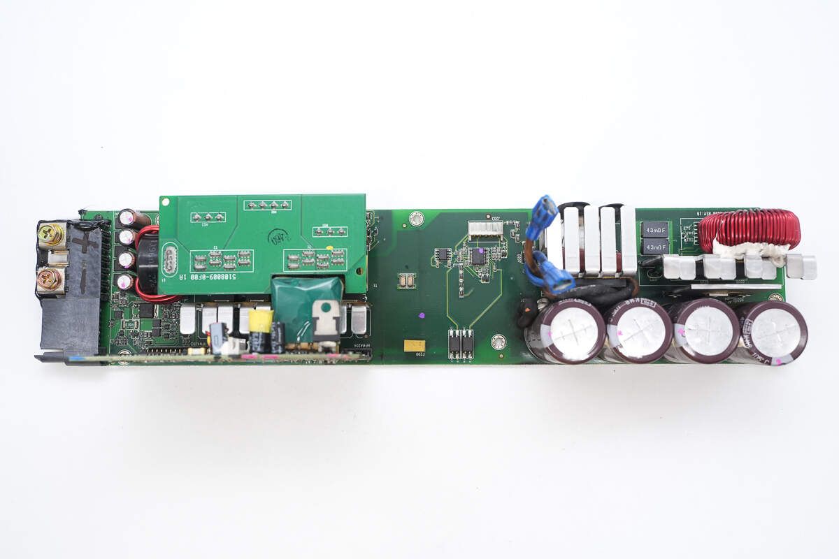
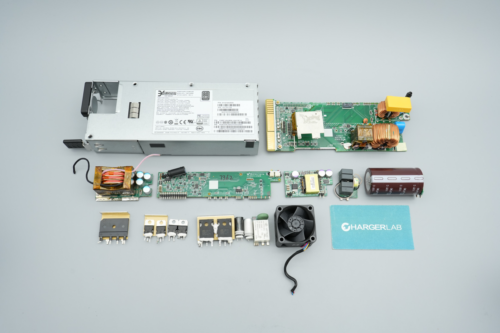
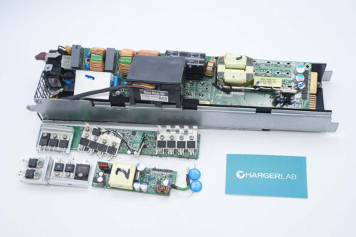
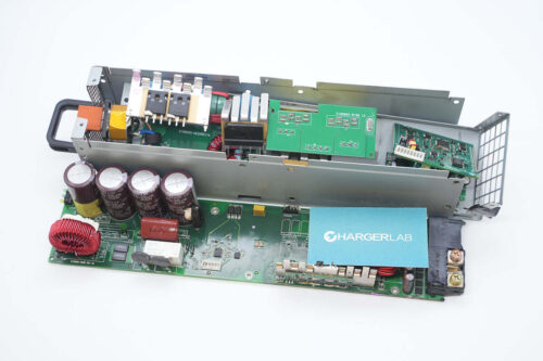
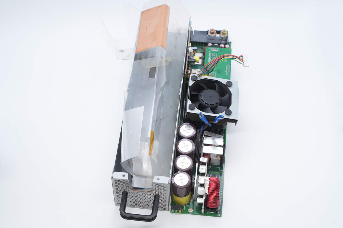
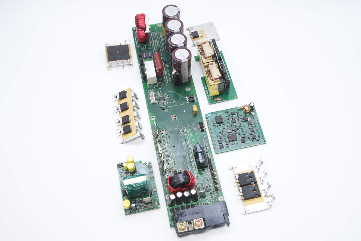
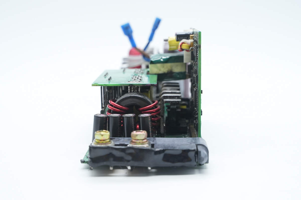
Front view of the PCBA module:
The right side contains the PFC circuit, including the rectifier bridge, PFC MOSFETs, PFC rectifier, PFC boost inductor, and high-voltage filter capacitors.
The left side houses the forward transformer, control PCB, auxiliary power PCB, filter inductors and capacitors, as well as the output connector.

The back features the PFC controller and an Op-Amp.
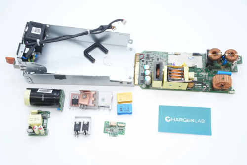
The input side includes indicator lights, high-voltage filter capacitors, PFC MOSFETs, a PFC rectifier, and a PFC boost inductor.
Disassemble the PCBA module.

The bridge rectifier is mounted on the heatsink.
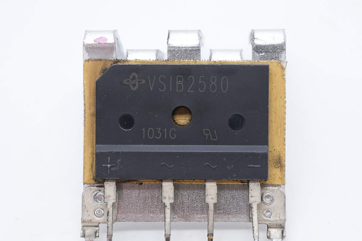
The bridge rectifier is from VISHAY, model VSIB2580, rated at 800V 25A, and uses a GSIB-5S package.
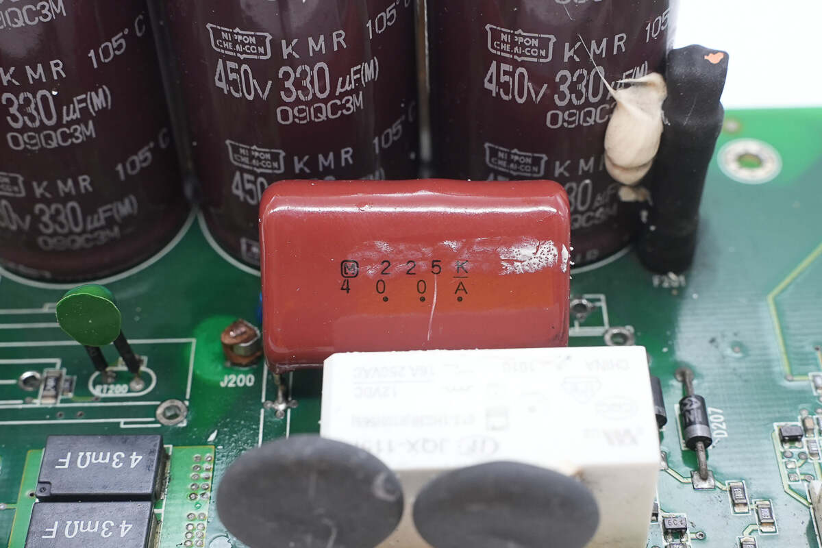
The film capacitor is from Panasonic, with a specification of 2.2μF 400V.
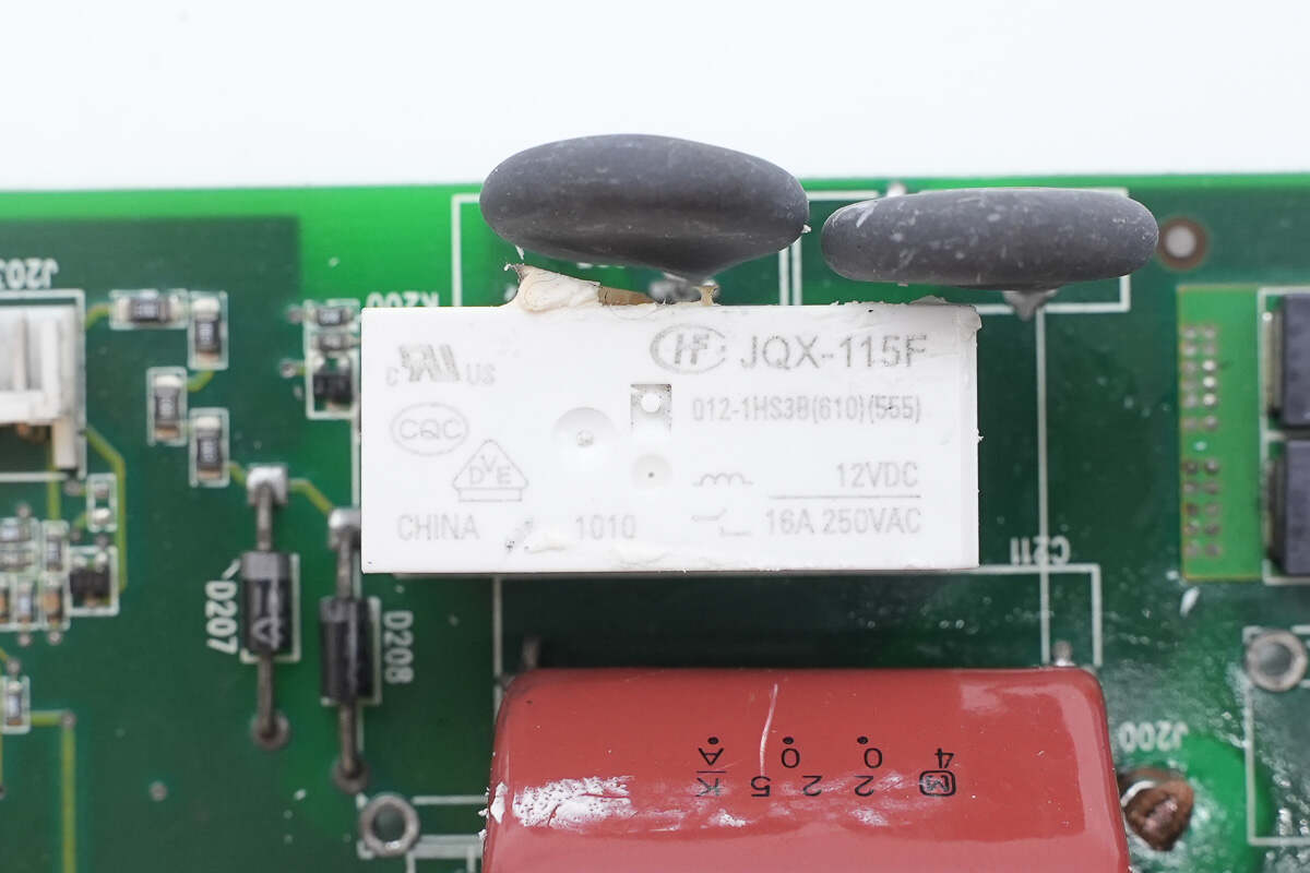
The soft-start relay is from HONGFA, model JQX-115F/012-1HS3B. It features a single normally open contact rated at 16A 250V, with a coil voltage of 12V.
Two thermistors are used to suppress inrush current during power-up, both insulated with heat-shrink tubing.
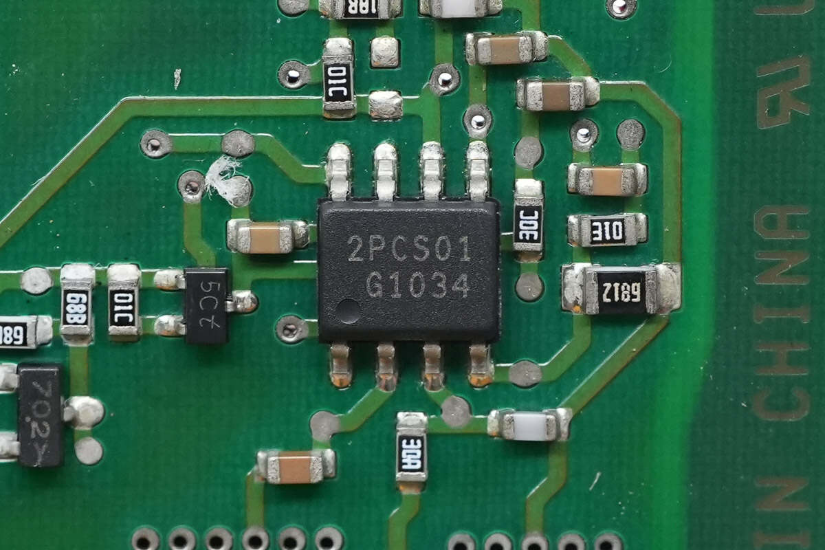
The PFC controller is from Infineon, model ICE2PCS01G. It operates in CCM, supports a wide VCC supply voltage range, and features external loop compensation for increased design flexibility. It also includes output overvoltage protection and open-loop protection, and comes in a DSO-8 package.
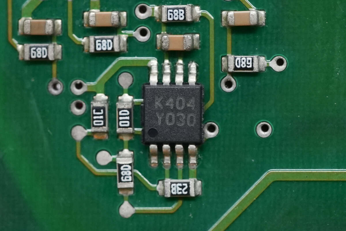
The dual operational amplifier is from STMicroelectronics, marked with K404, model LM358AST. It is a general-purpose dual op amp used for PFC current sensing amplification and comes in a MiniSO8 package.
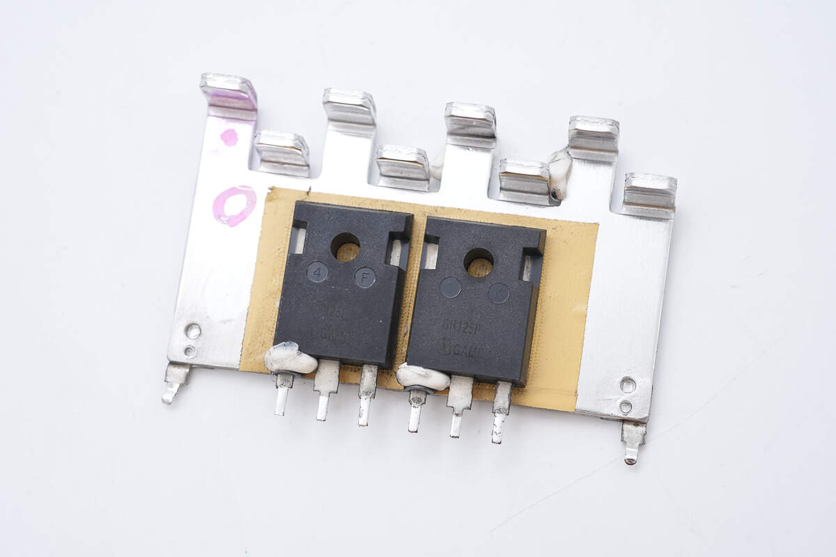
The PFC MOSFETs are mounted on the heatsink.
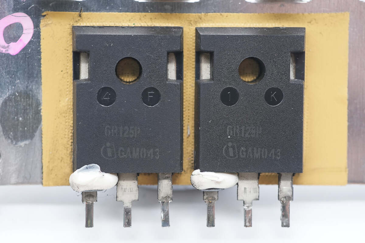
The PFC MOSFETs are from Infineon, marked with 6R125P, model IPW60R125CP. They are N-channel MOSFETs with a voltage rating of 650V and an on-resistance of 125mΩ, housed in a TO-247-3-1 package.
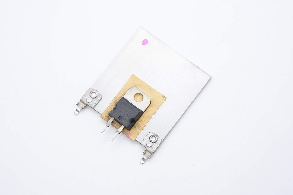
The PFC rectifier is also mounted on the heatsink.
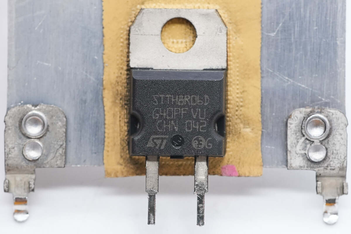
The PFC rectifier is from STMicroelectronics, model STTH8R06D. It is a Turbo 2 ultra-fast diode rated at 600V and 8A, packaged in a TO-220AC case.
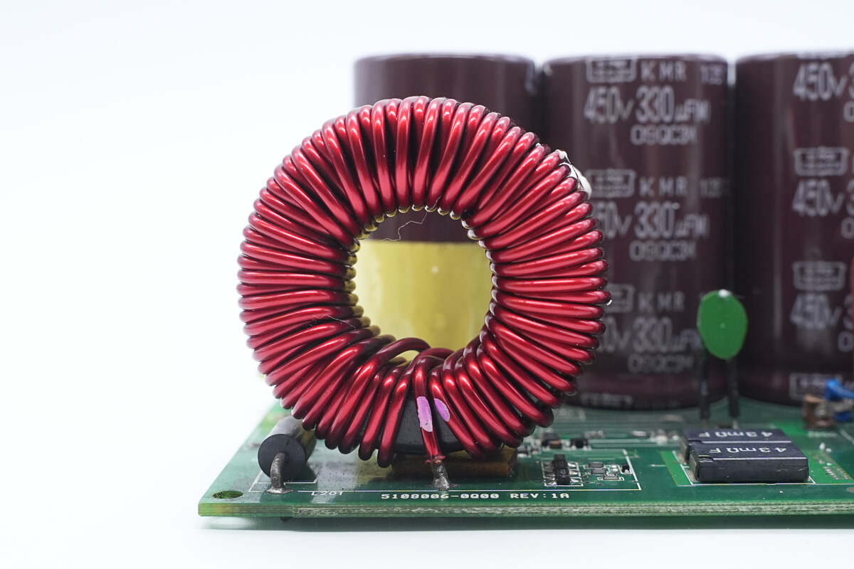
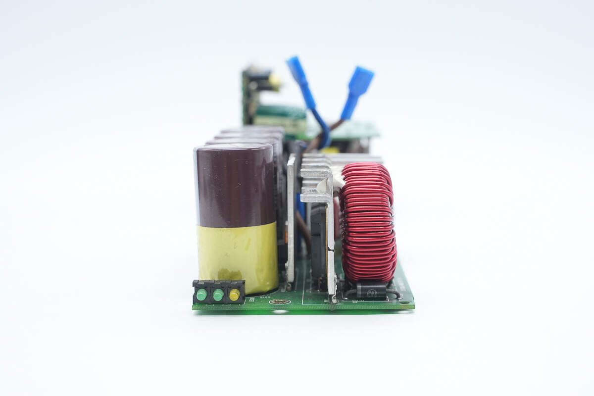
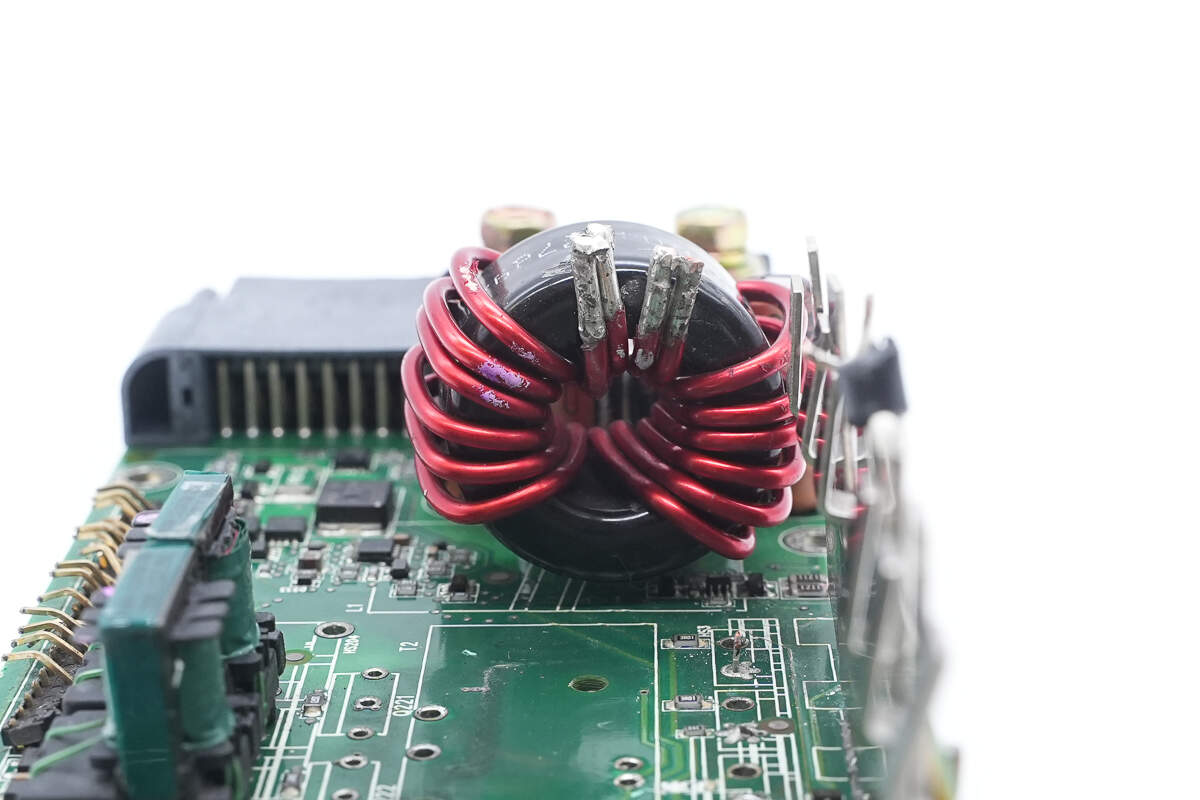
The PFC boost inductor uses a toroidal winding and is insulated at the bottom with a Bakelite board.
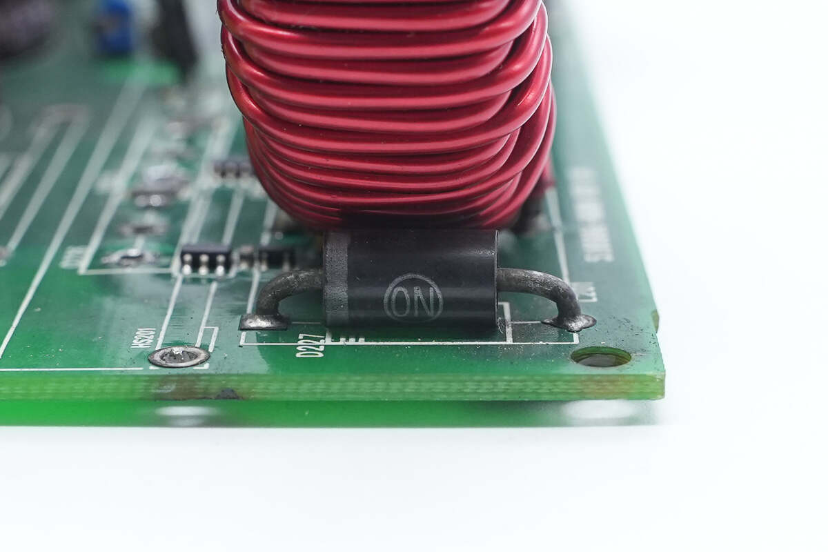
The bypass diode is from Onsemi.
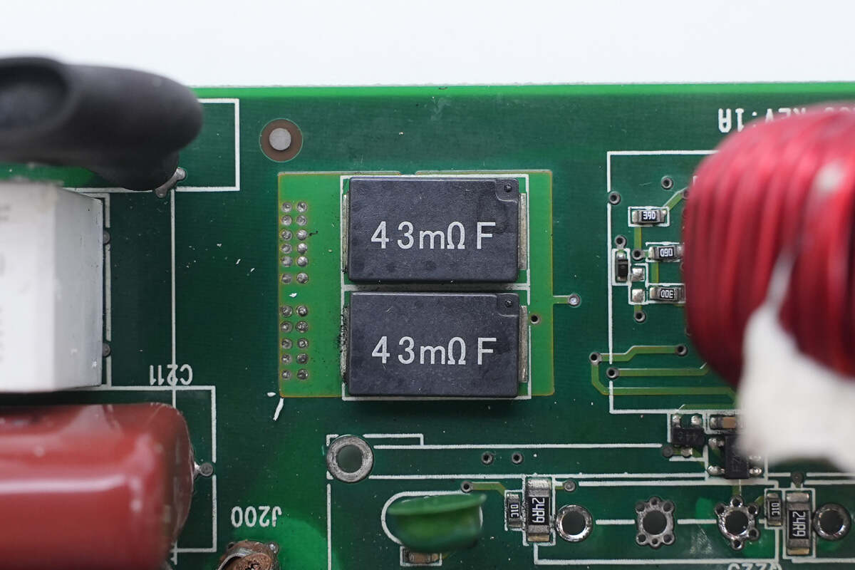
Two 43mΩ current-sense resistors are connected in parallel to detect the current through the PFC MOSFETs.
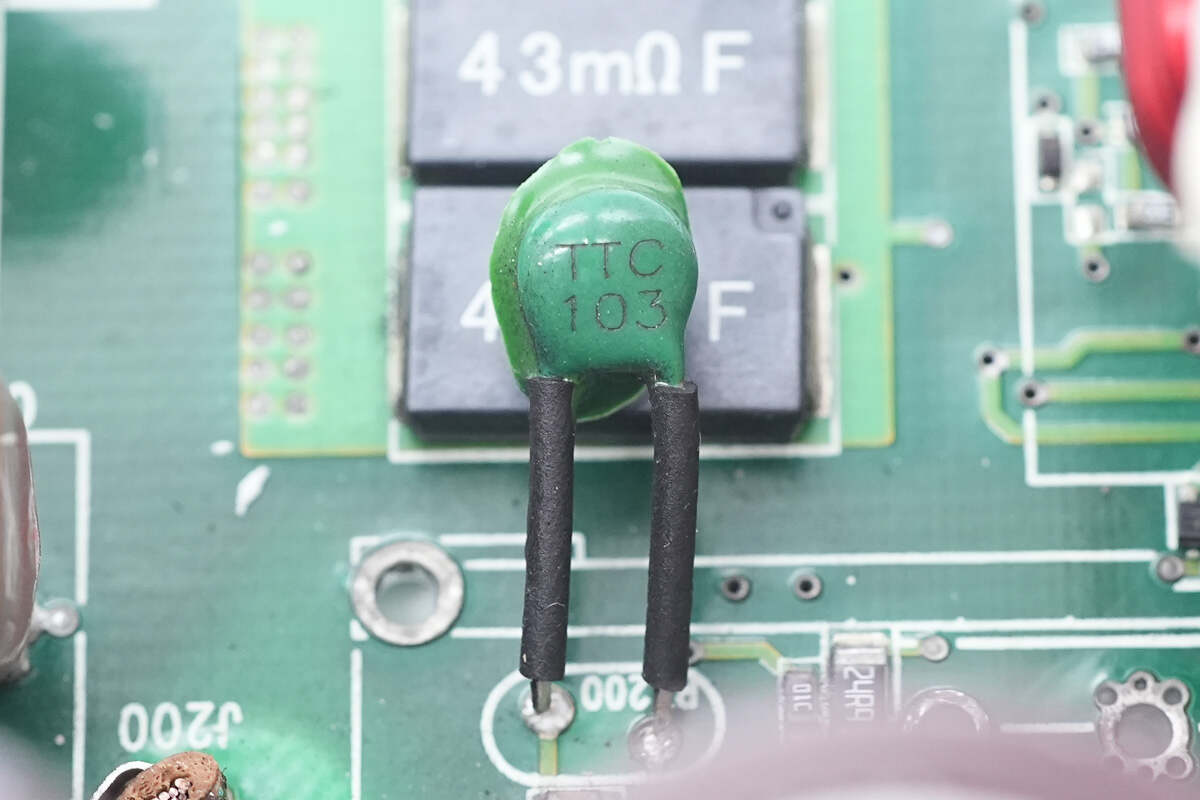
A 10K thermistor is used to monitor the temperature of the PFC MOSFETs.
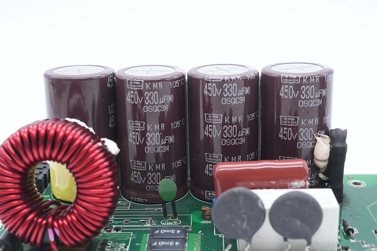
The high-voltage filter capacitors are from NCC, part of the KMR series of compact electrolytic capacitors, rated at 450V 330μF.
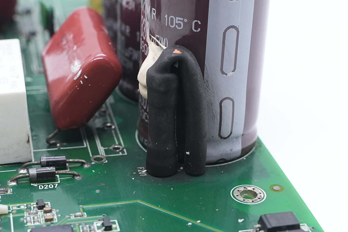
The PFC output fuse is insulated with heat-shrink tubing.
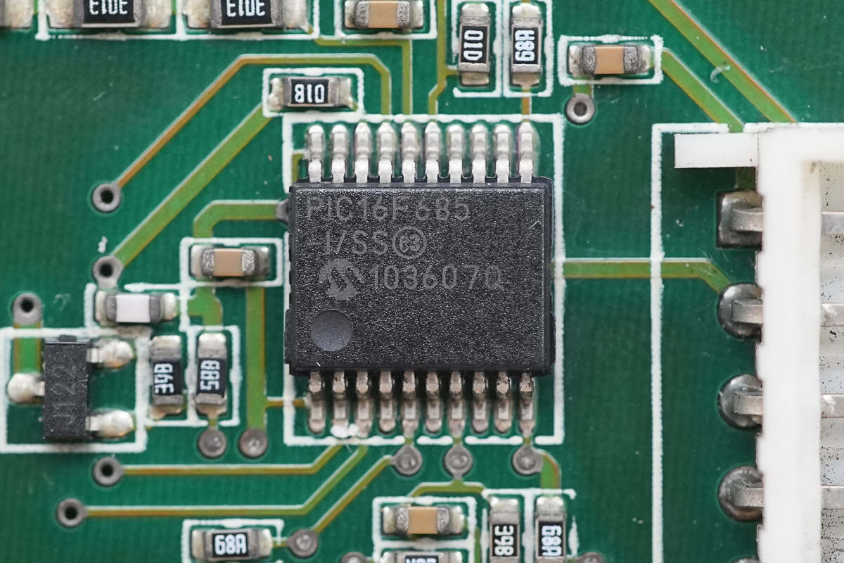
The MCU is from Microchip, model PIC16F685. It features a high-performance RISC core CPU, with 7KB of Flash memory, 256 bytes of SRAM, and 256 bytes of EEPROM. It also integrates a 10-bit ADC and comes in an SSOP-20 package.
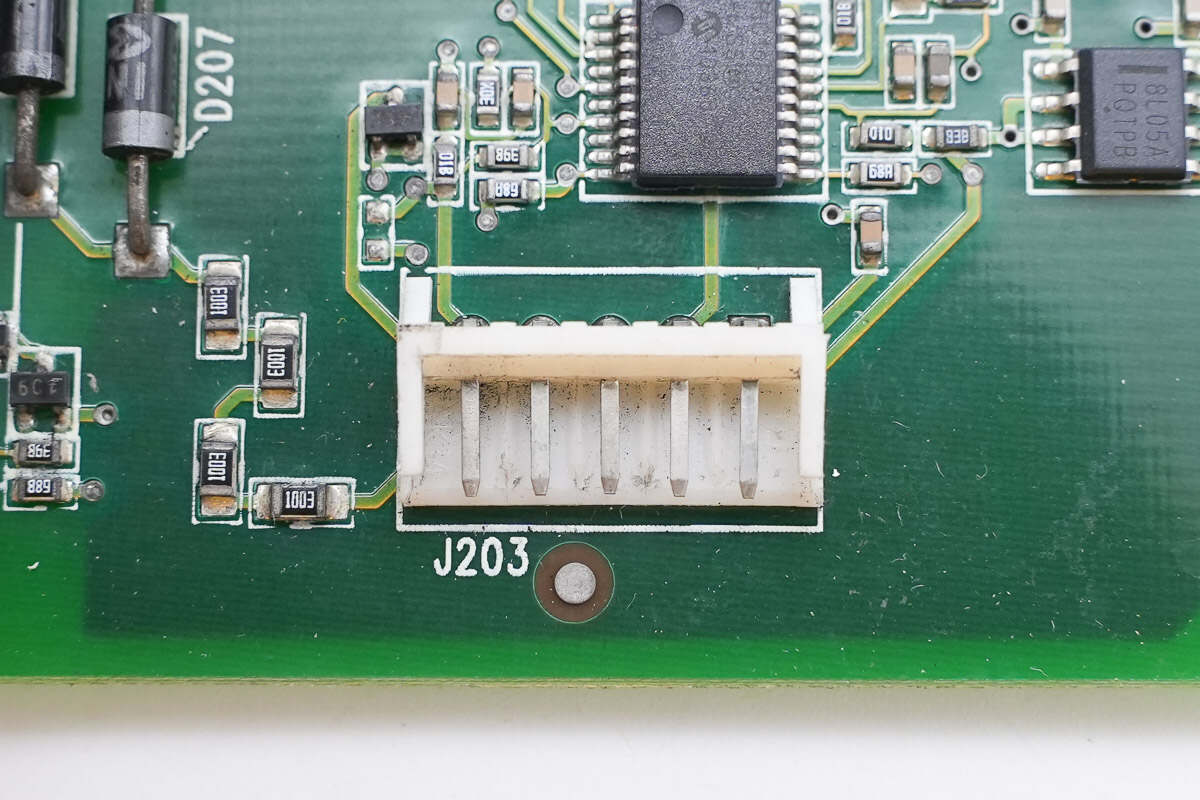
Close-up of the communication interface.
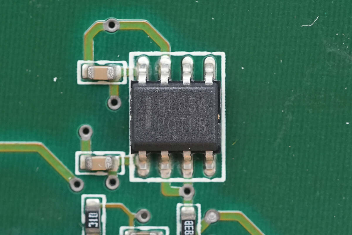
The regulator is from Onsemi, marked with 8L05A, model MC78L05A. It supports an input voltage of up to 30V, provides a 5V output, and delivers up to 100mA of output current. It comes in an SOIC-8 package.
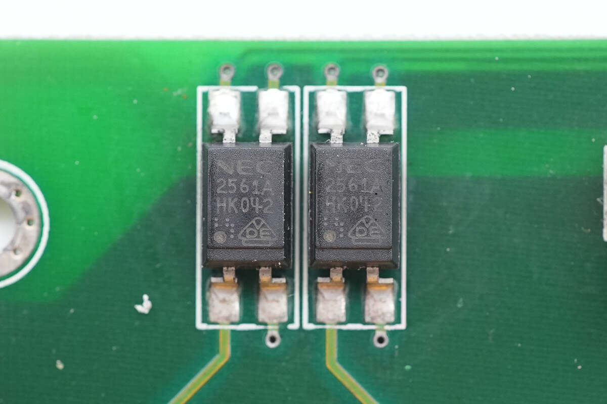
The optocouplers are from NEC, model 2561A, and are used for communication isolation.
The output side contains a transformer, a filter inductor, an auxiliary power PCB, and a control PCB.
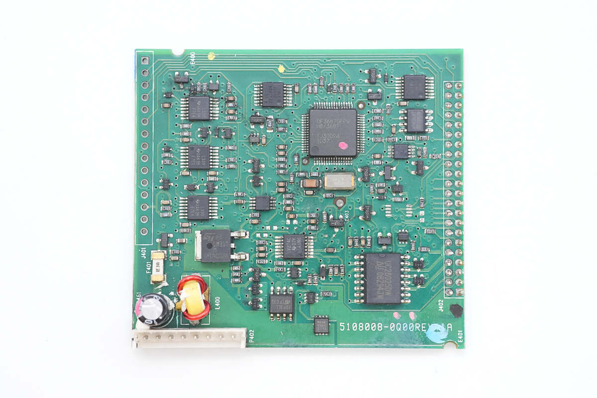
The control PCB houses the MCU, master control chip, op amp, voltage comparators, regulator, and NAND gates.
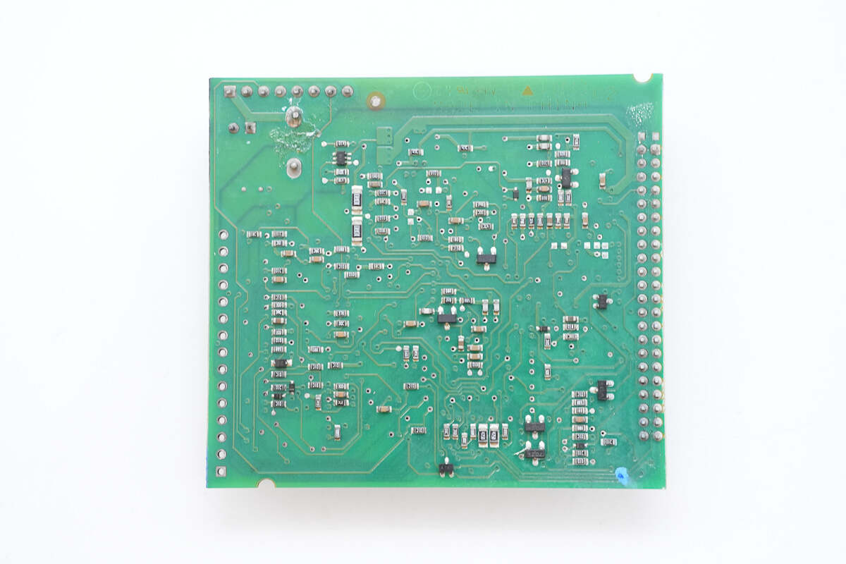
The back is populated with surface-mount components.
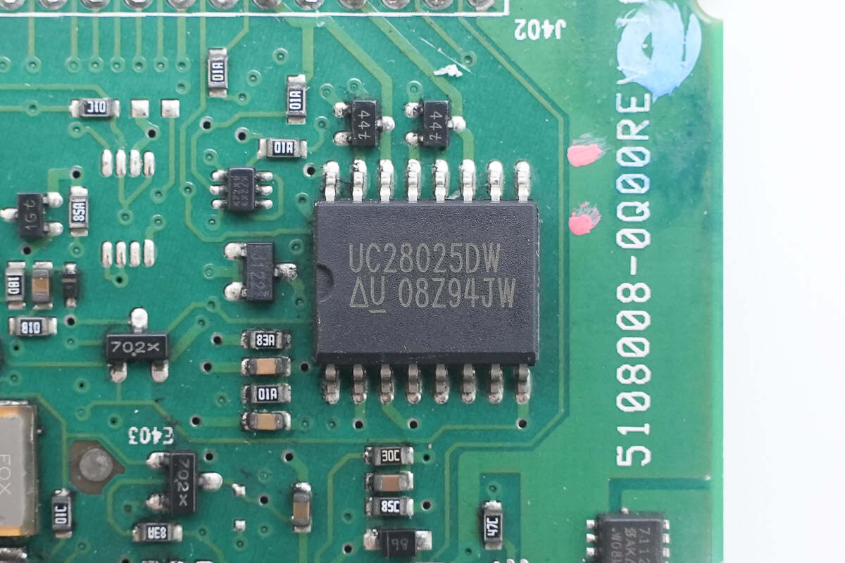
The master control chip is from TI, model UC28025. It is a cost-effective, dual-output high-speed PWM controller featuring interleaved dual outputs. It supports peak current mode, average current mode, and voltage mode control, with a switching frequency of up to 1 MHz. It comes in an SOIC-16 package.
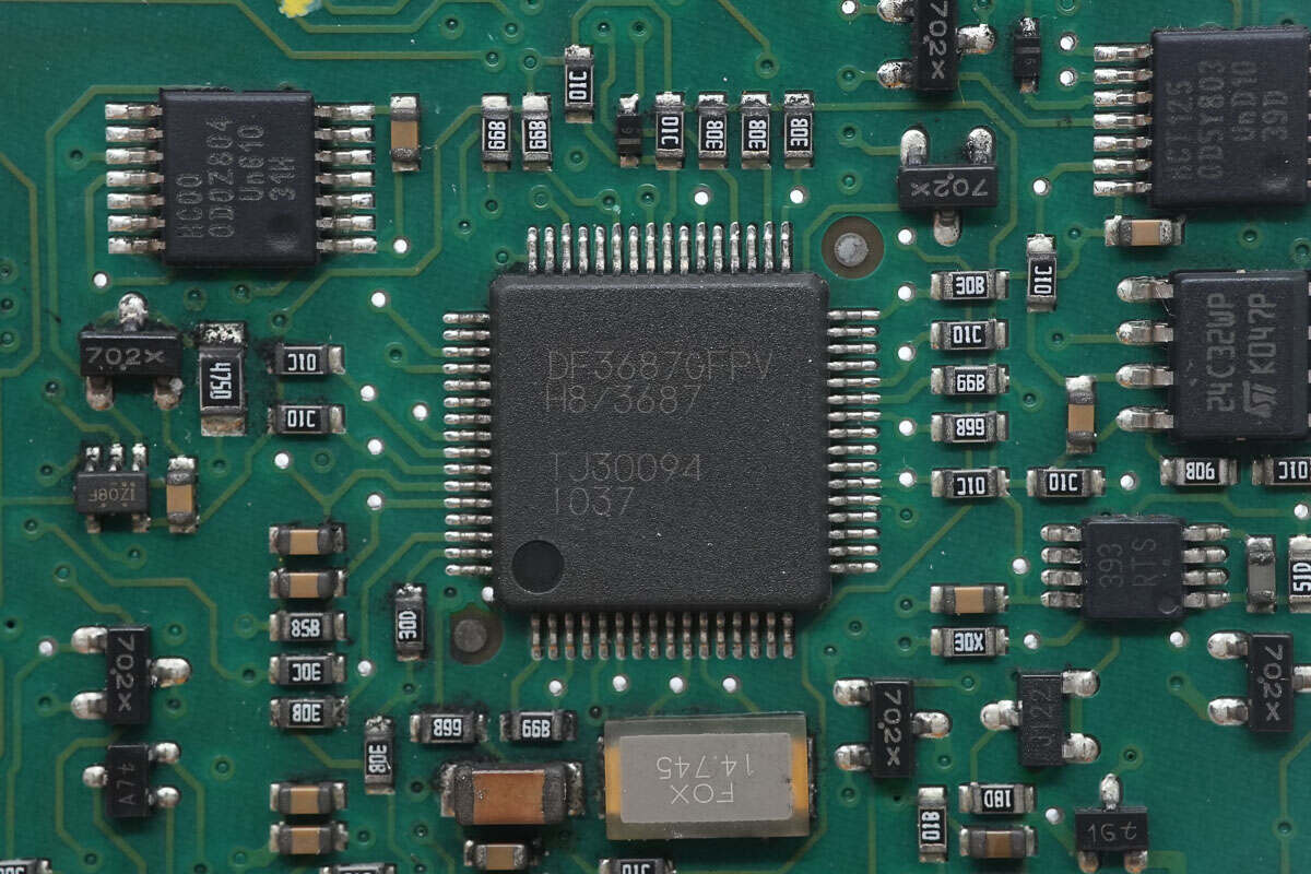
The MCU is from RENESAS, model HD64F3687G. It features an H8/300H 32-bit core running at 20 MHz, with 56 KB of ROM and 4 KB of RAM, and comes in an LQFP-64 package.
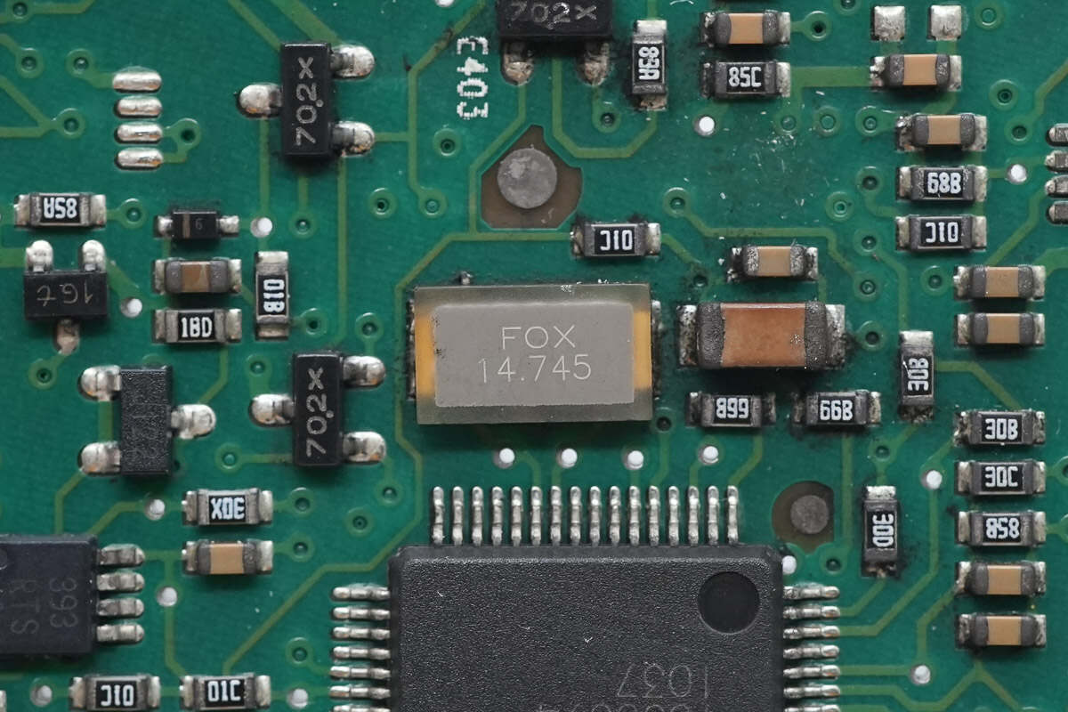
Close-up of the 14.745 MHz crystal oscillator.
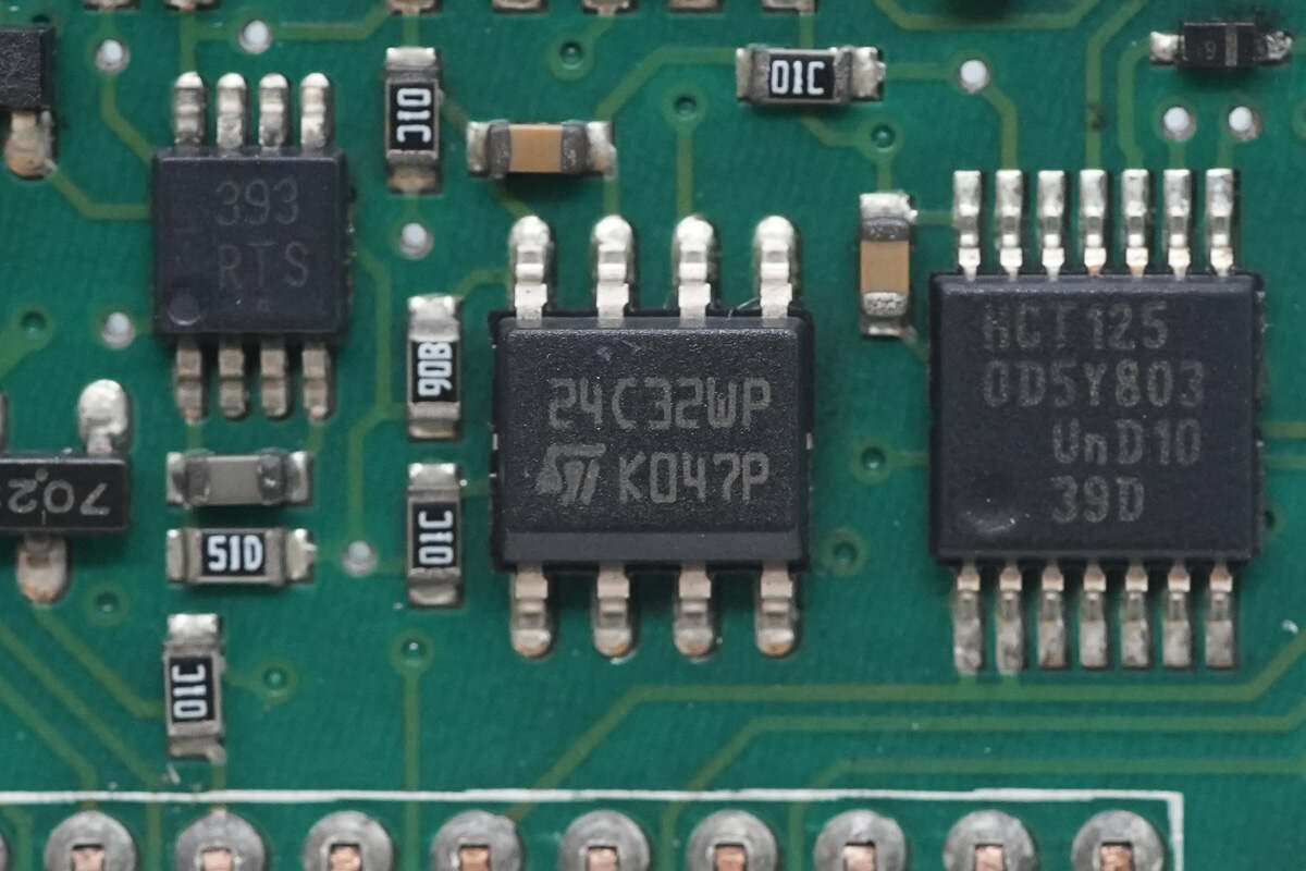
The memory chip is from STMicroelectronics, model M24C32WP. It has a capacity of 4KB and comes in an SO8 package.
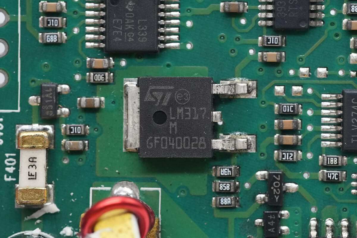
The STMicroelectronics LM317 regulator is used to provide regulated power to the MCU.
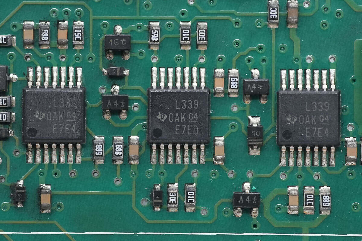
The voltage comparator is from TI, model LM339. It is a quad differential comparator and comes in a TSSOP-14 package.
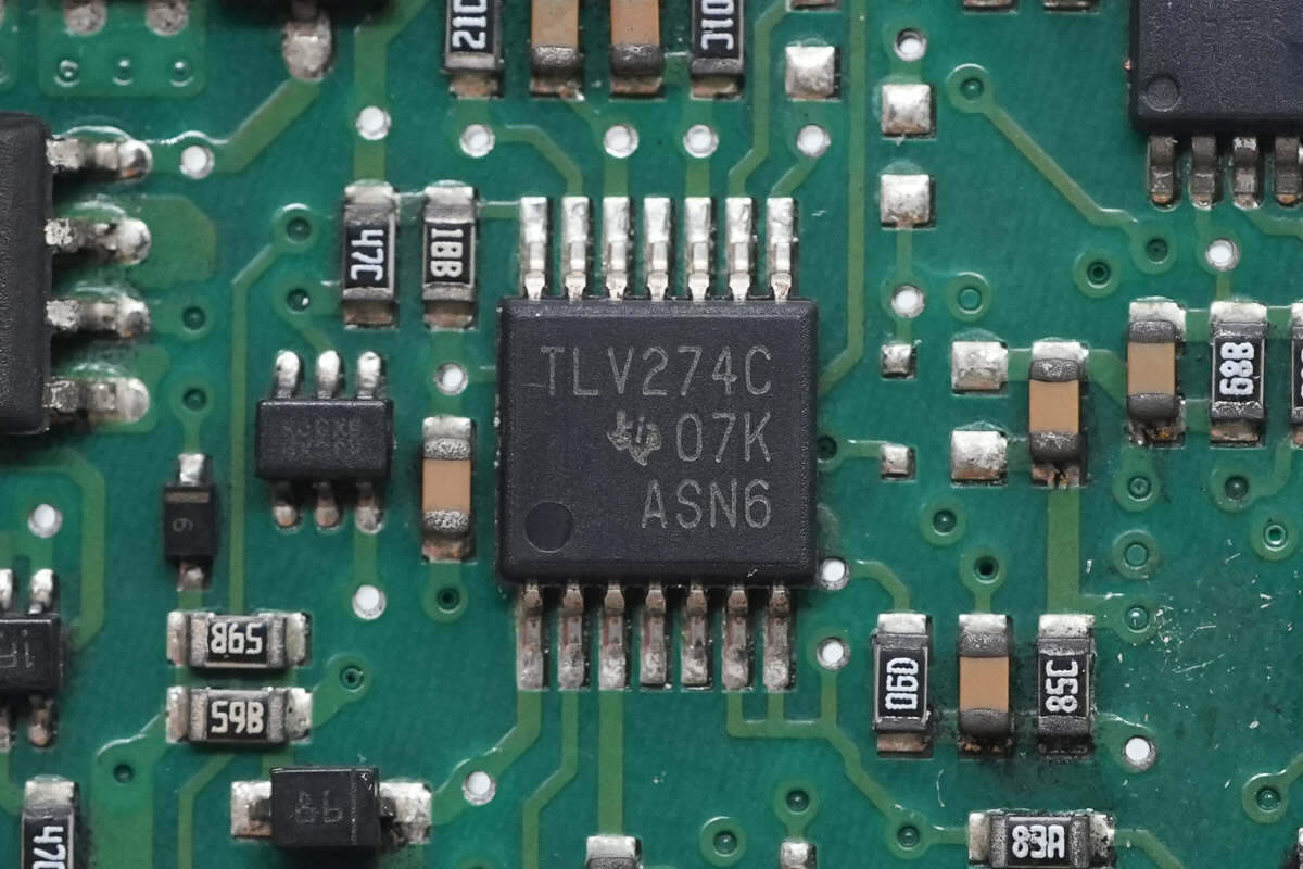
The operational amplifier is from TI, model TLV274C. It is a quad op-amp with rail-to-rail output, housed in a TSSOP-14 package.
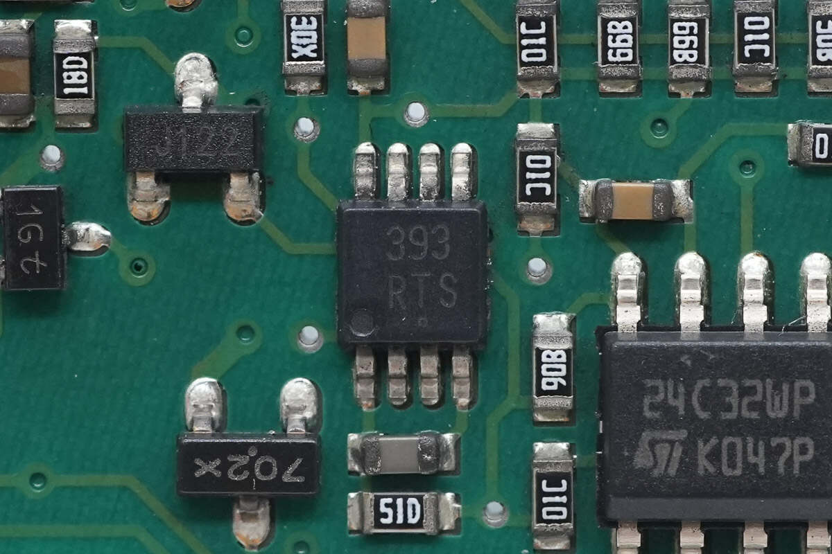
Close-up of the 393 dual voltage comparator.
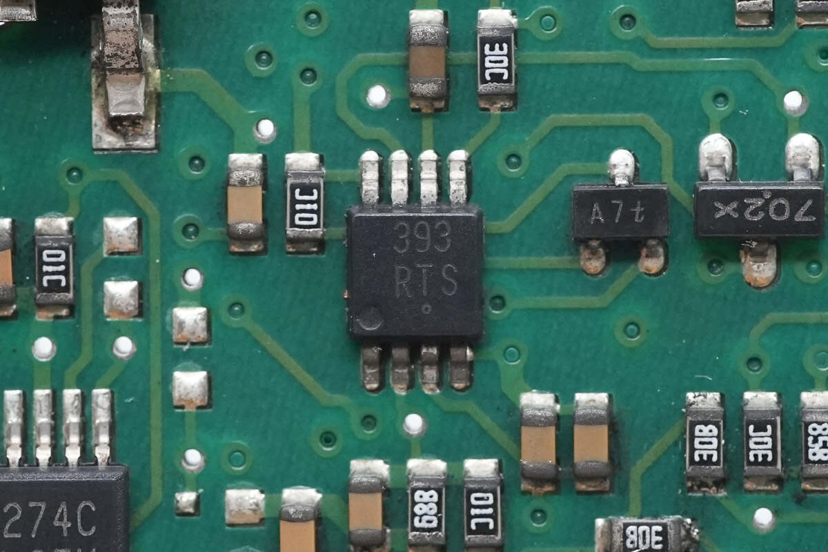
Close-up of the other 393 voltage comparator.
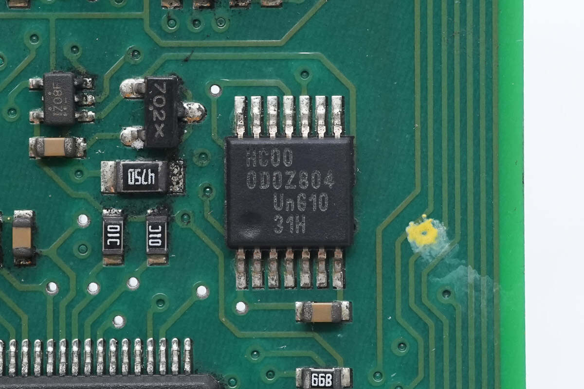
The NAND gate chip is from Nexperia, marked HC00, model 74HC00. It is a quad 2-input NAND gate and comes in a TSSOP-14 package.
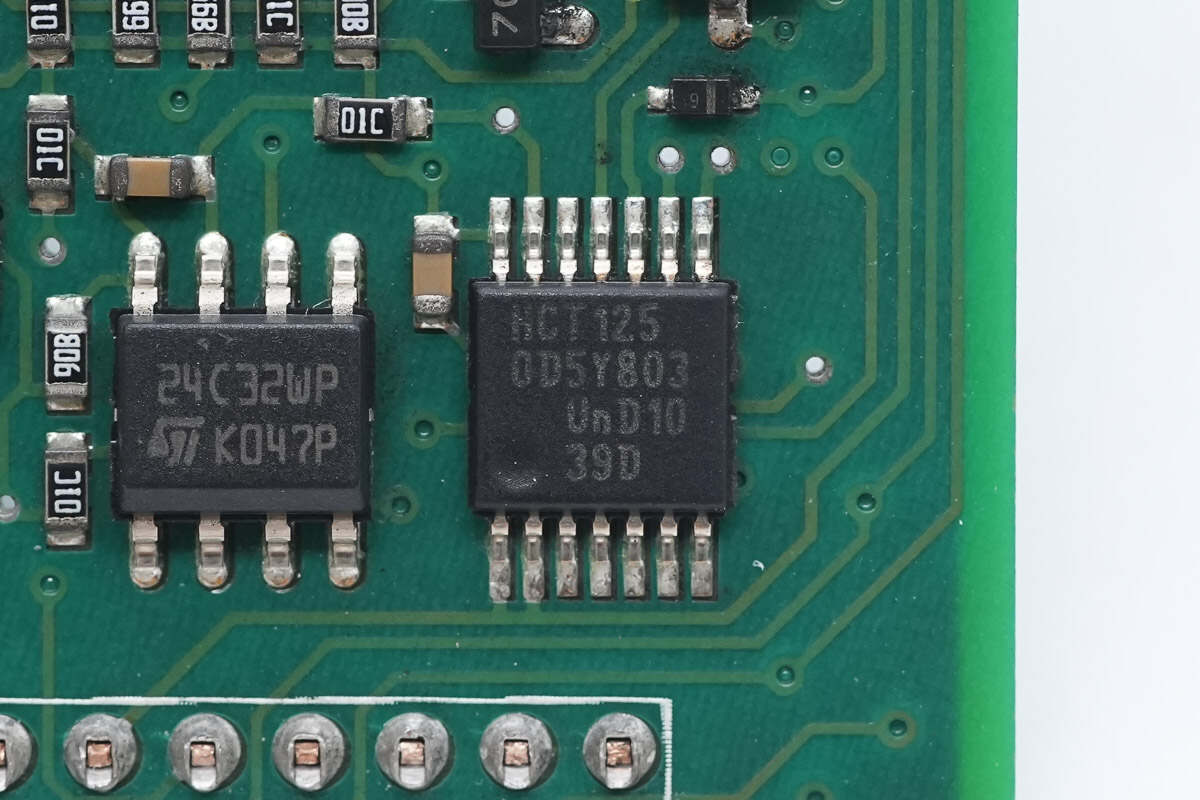
The buffer chip is from Nexperia, marked HCT125, model 74HCT125. It is a quad buffer with tri-state outputs, housed in a TSSOP-14 package.
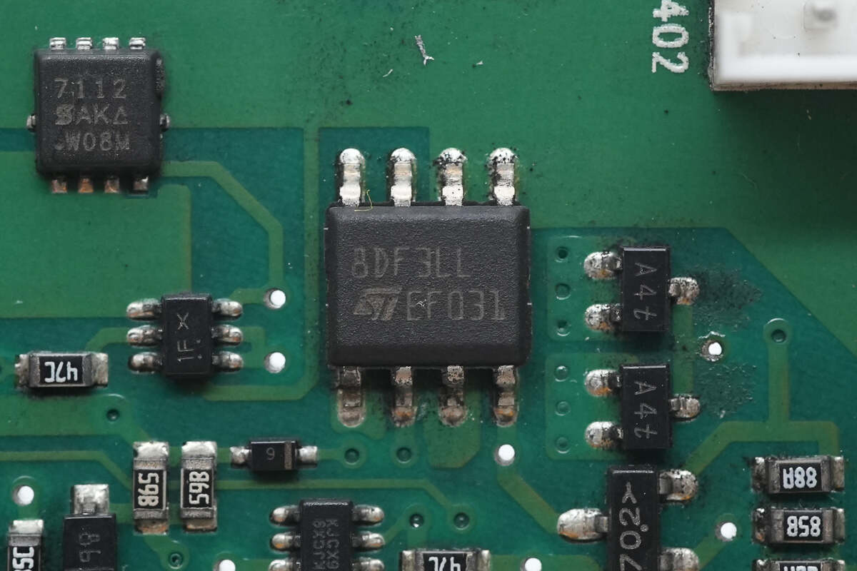
The MOSFET is from STMicroelectronics, model STS8DNF3LL. It is a dual NMOS with a voltage rating of 30V and an on-resistance of 17mΩ, packaged in an SO-8 case.
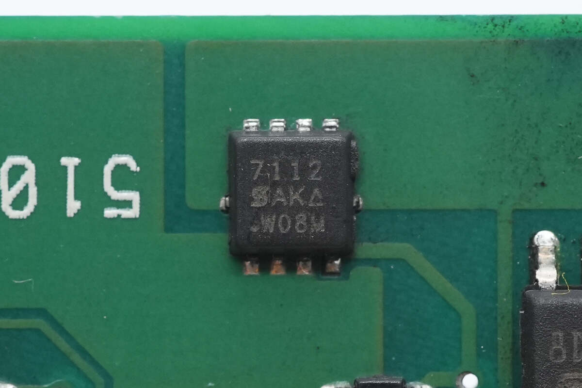
The other MOSFET is from VISHAY, model Si7112DN. It is an NMOS with a voltage rating of 30V and an on-resistance of 7.5mΩ, housed in a PowerPAK 1212-8 package.

The fuse for the fan power supply is rated at 3A.
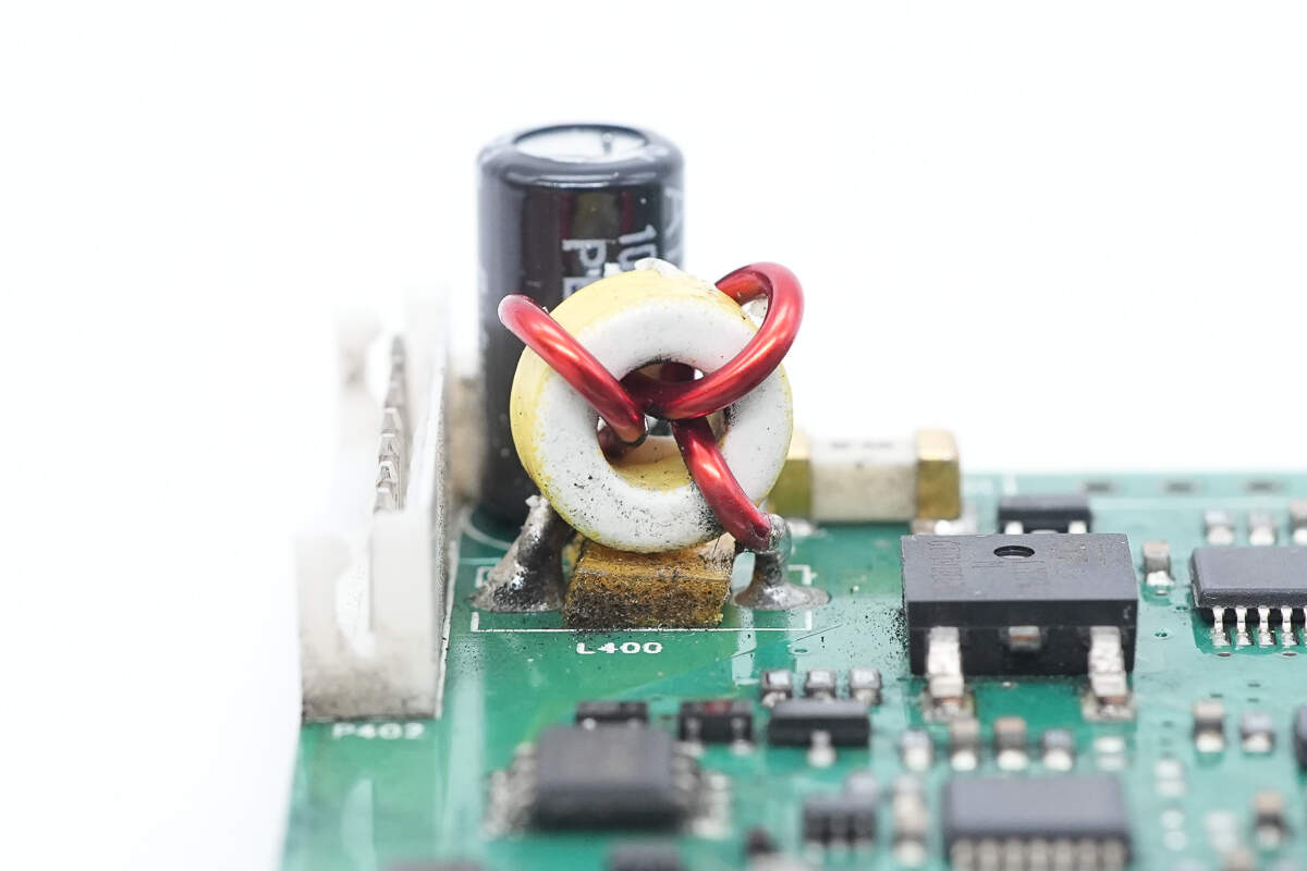
The filter inductor uses a toroidal winding construction.
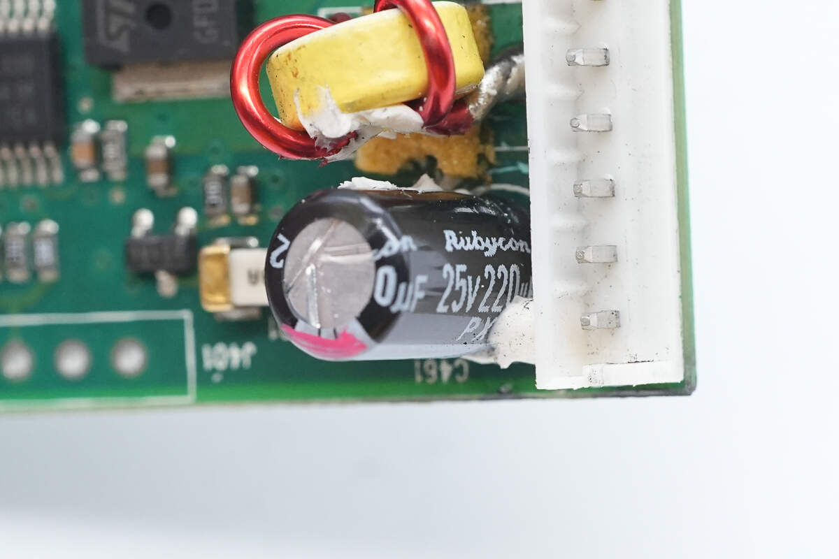
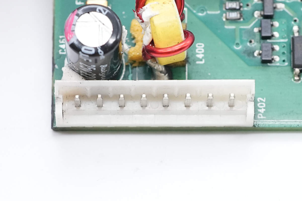
The filter capacitor is from Rubycon, with a specification of 25V 220μF.
Close-up of the connector for the cooling fan.
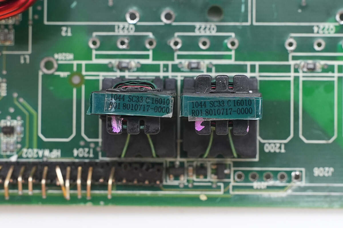
Two isolation transformers are used for driving the forward converter MOSFETs.
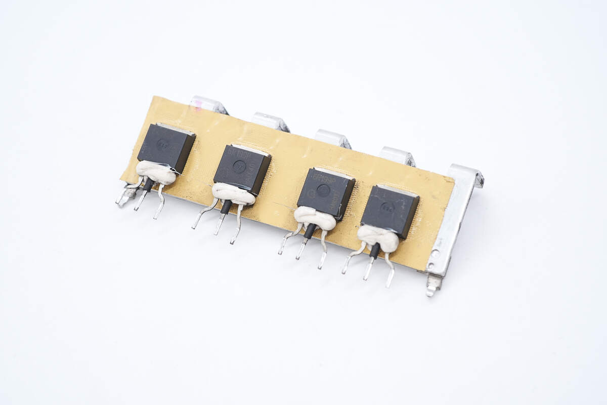
The forward converter MOSFETs are mounted on the heatsink.
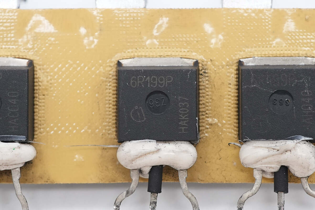
The forward converter MOSFETs are from Infineon, marked with 6R199P, model IPI60R199CP. They are N-channel MOSFETs with a voltage rating of 650V and an on-resistance of 199mΩ, housed in a TO-262 package.
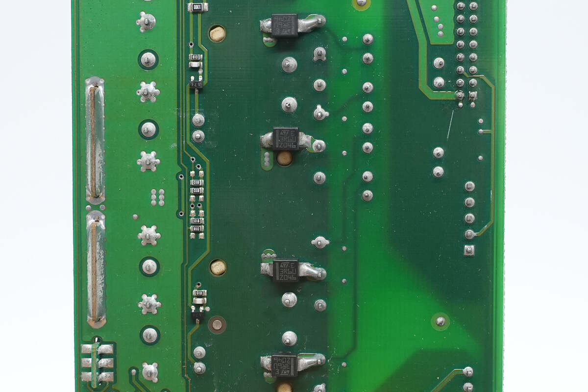
The ultra-fast recovery diode is used for leakage energy recovery.
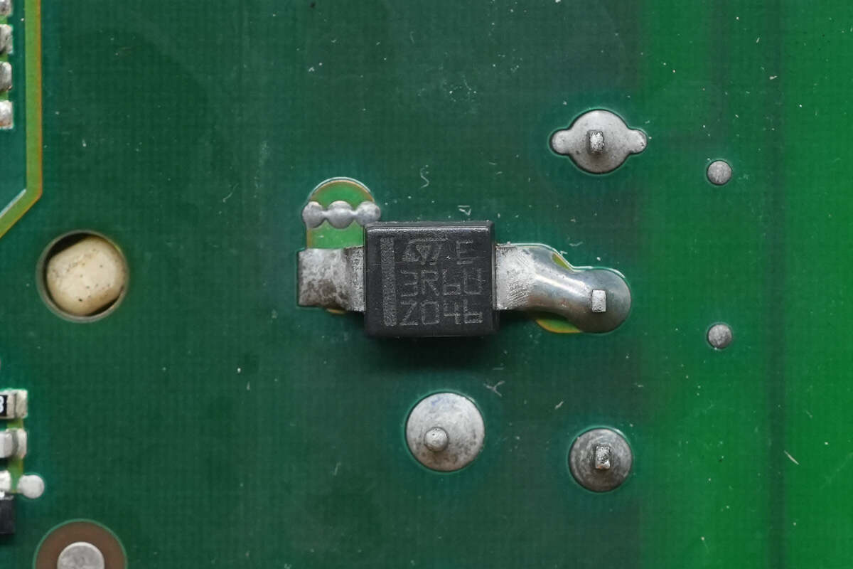
The ultra-fast recovery diode is from STMicroelectronics, model STTH3R06U, rated at 3A 600V, and comes in an SMB package.
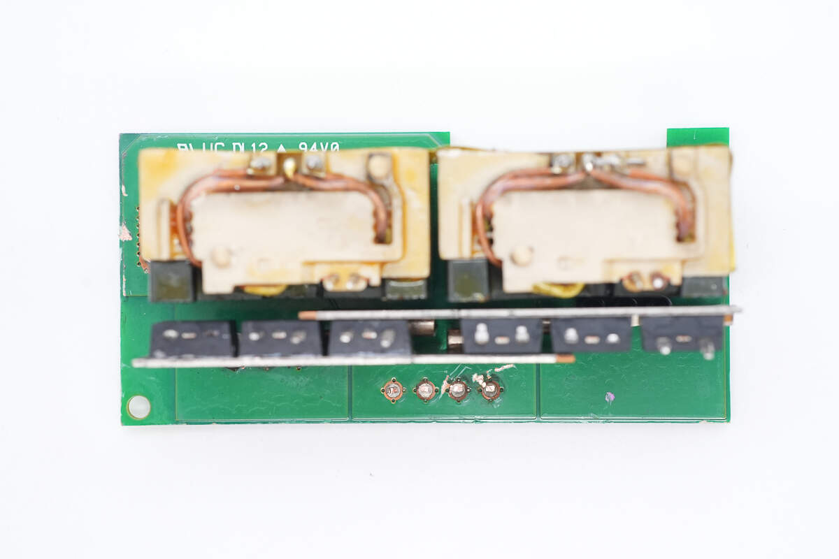
The transformer and synchronous rectifiers are mounted on the connection PCB.
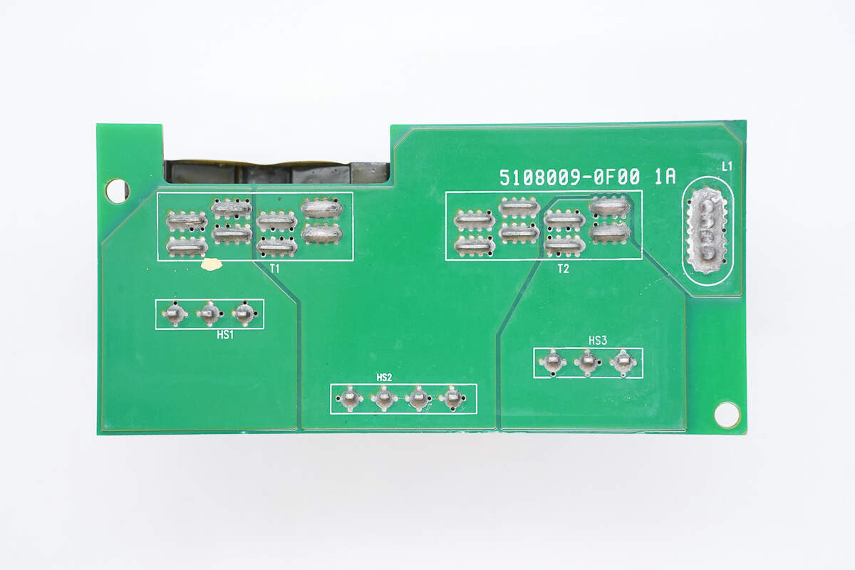
The transformer secondary windings are connected using copper strips soldered in place.
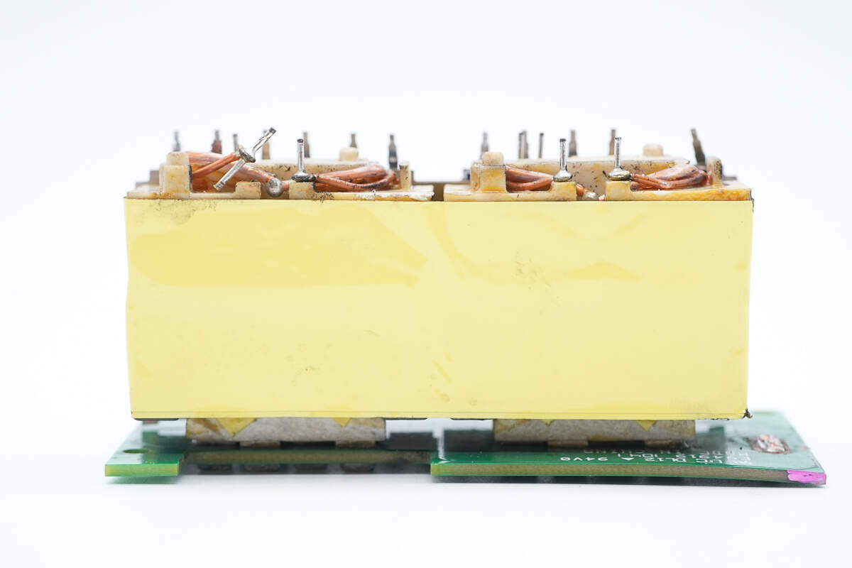
The transformer core is insulated with winding tape.
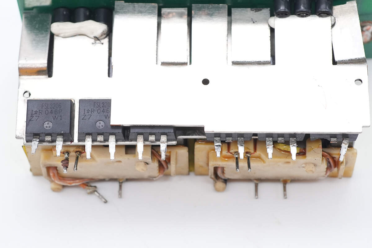
The synchronous rectifiers are soldered onto the copper strip.
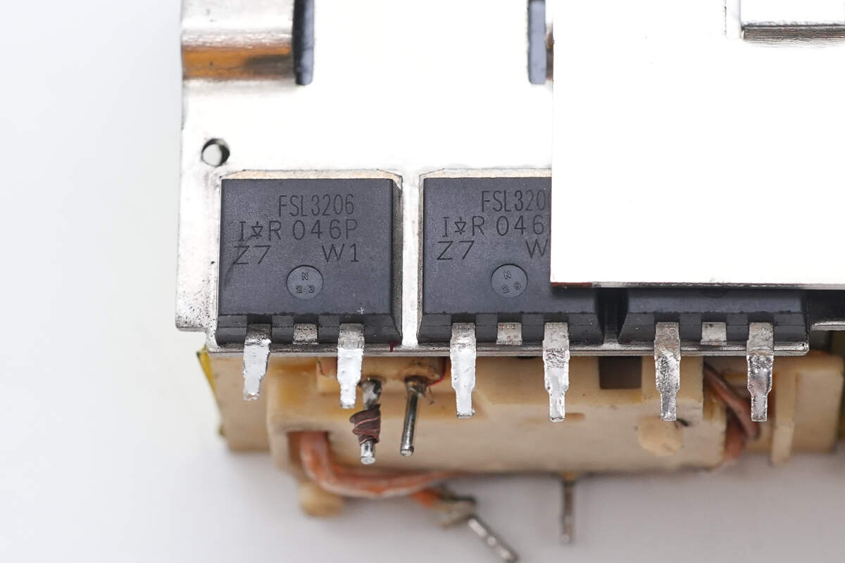
The synchronous rectifiers are from Infineon, model IRFSL3206. They are N-channel MOSFETs with a voltage rating of 60V and an on-resistance of 2.4mΩ, housed in a TO-262 package.
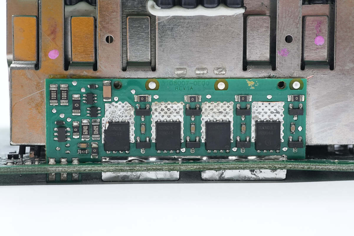
The heatsink also serves as a connector and has the freewheeling PCB soldered onto it.
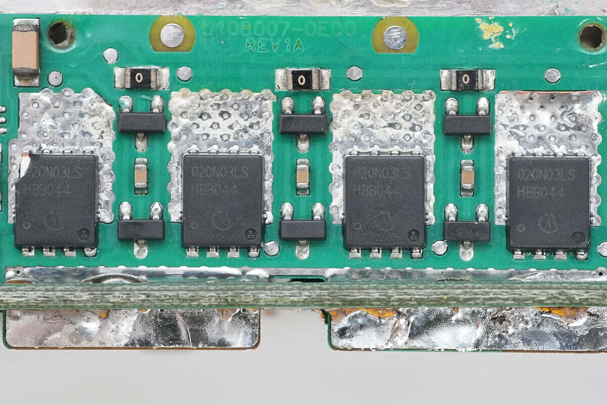
The freewheeling PCB contains four synchronous rectifiers.
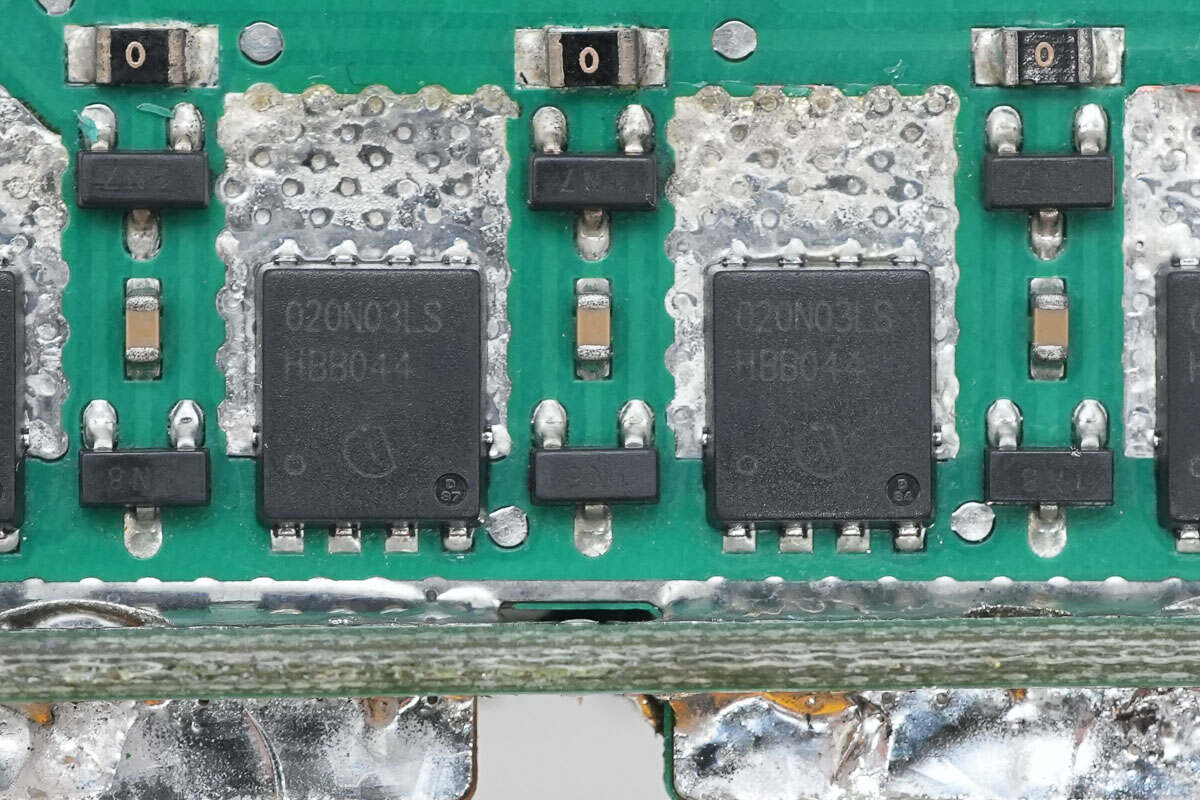
The synchronous rectifiers are from Infineon, model BSC020N03LS. They are N-channel MOSFETs with a voltage rating of 30V and an on-resistance of 2mΩ, housed in a TDSON-8 package.
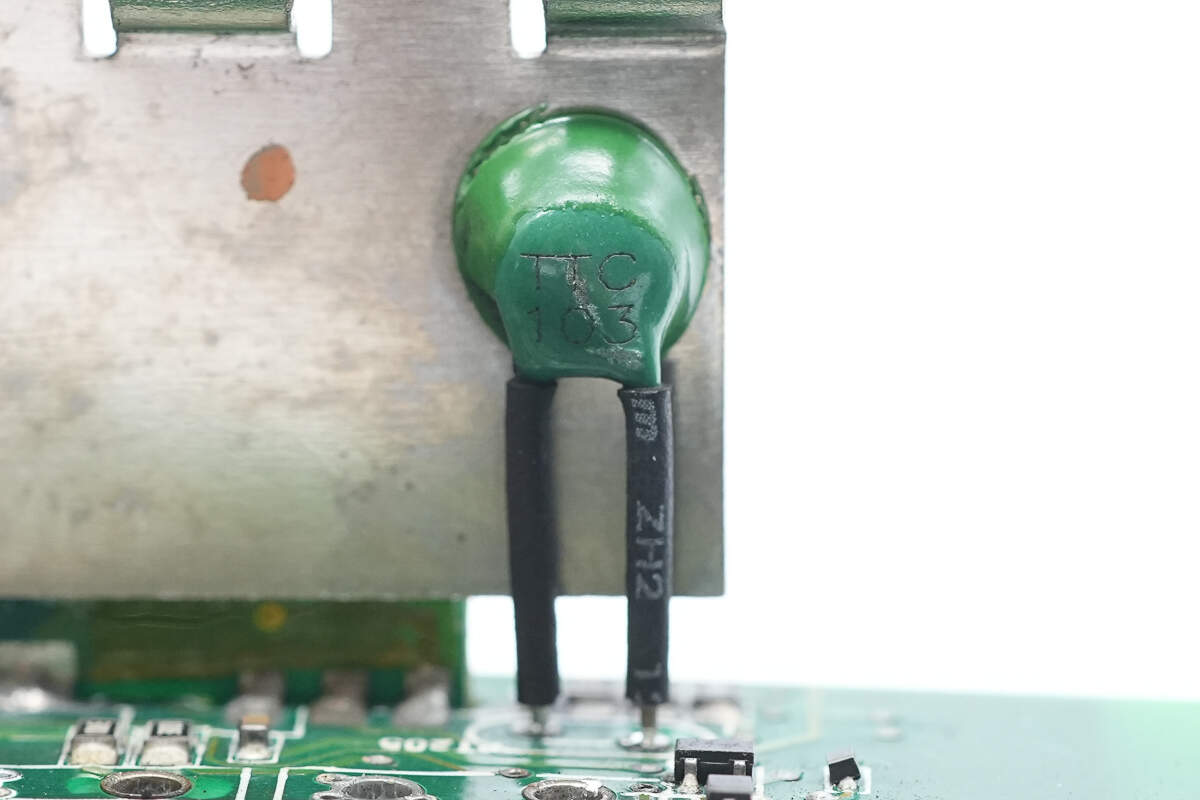
On the other side of the heatsink, there is a thermistor.
The driver is from TI, model UCC27424. It is a dual-channel gate driver with a 4A output current, used for driving synchronous rectifiers, and comes in a VSSOP-8 package.
The energy storage inductor uses a four-wire bifilar winding.
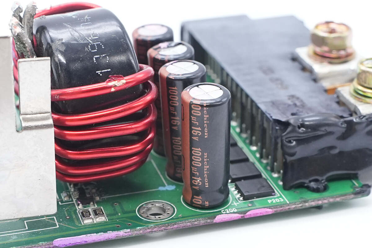
The filter capacitors are from Nichicon, with a specification of 1000μF 16V.
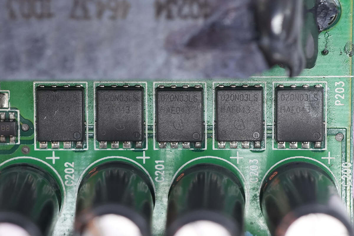
The output side is equipped with five VBUS MOSFETs.
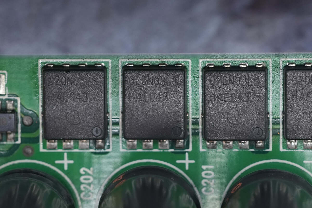
The VBUS MOSFETs are from Infineon, model BSC020N03LS.
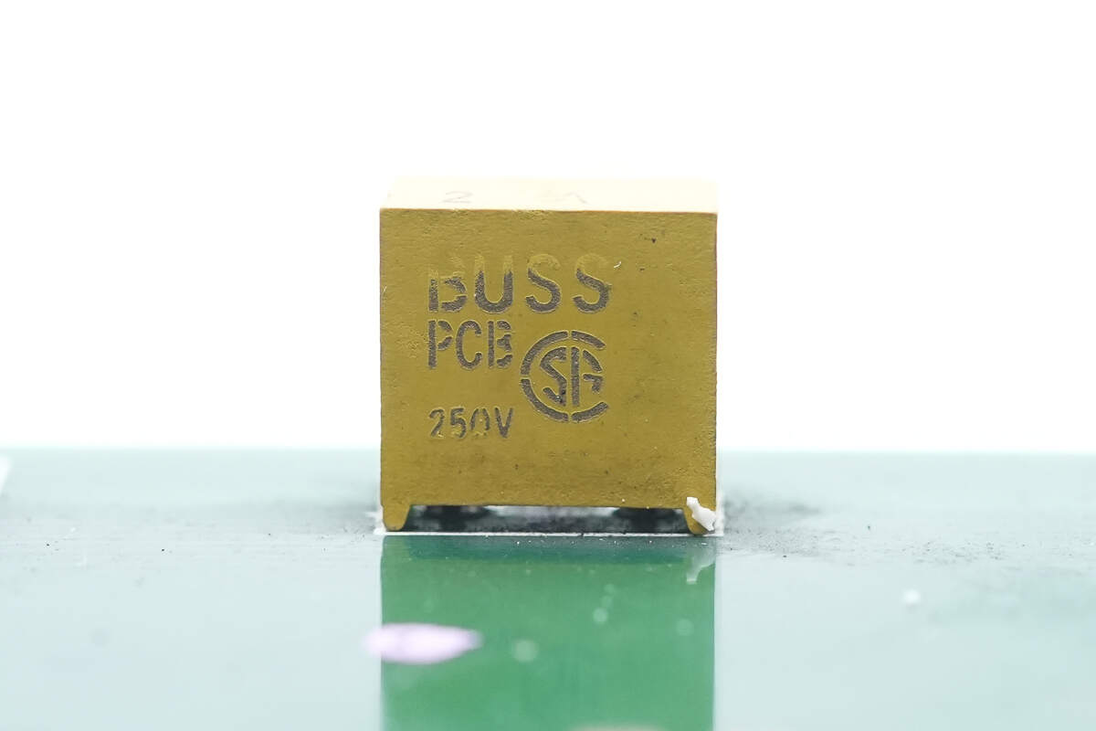
The auxiliary power input fuse is from BUSS, rated at 2A.
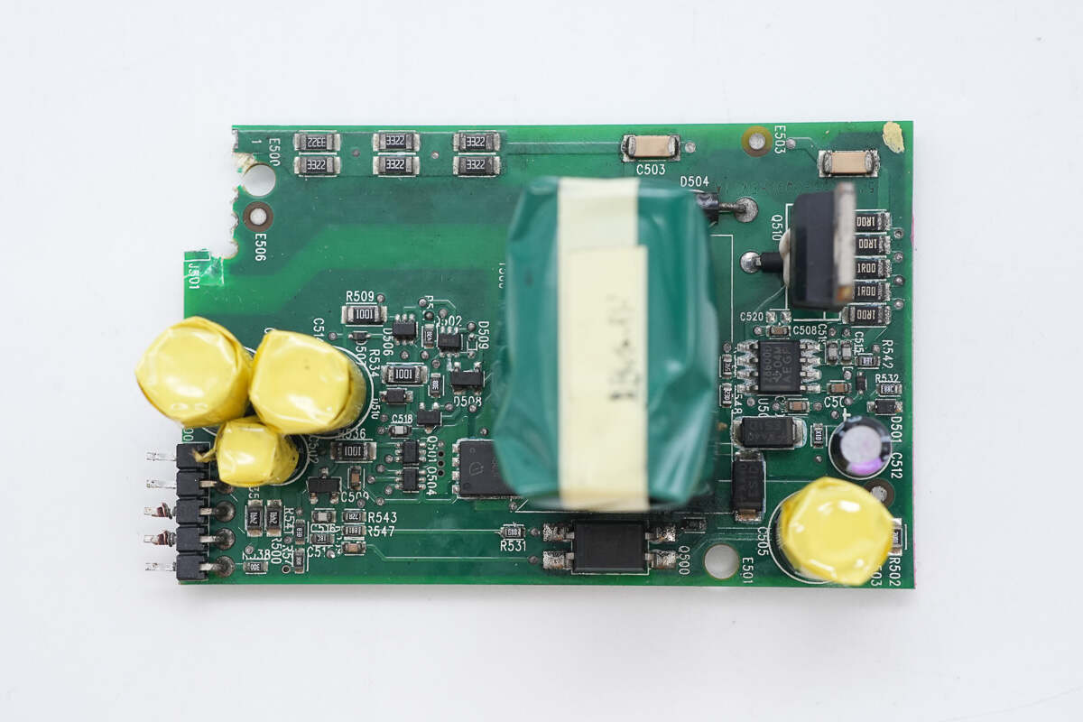
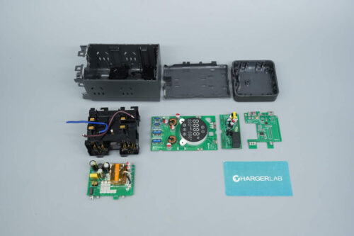
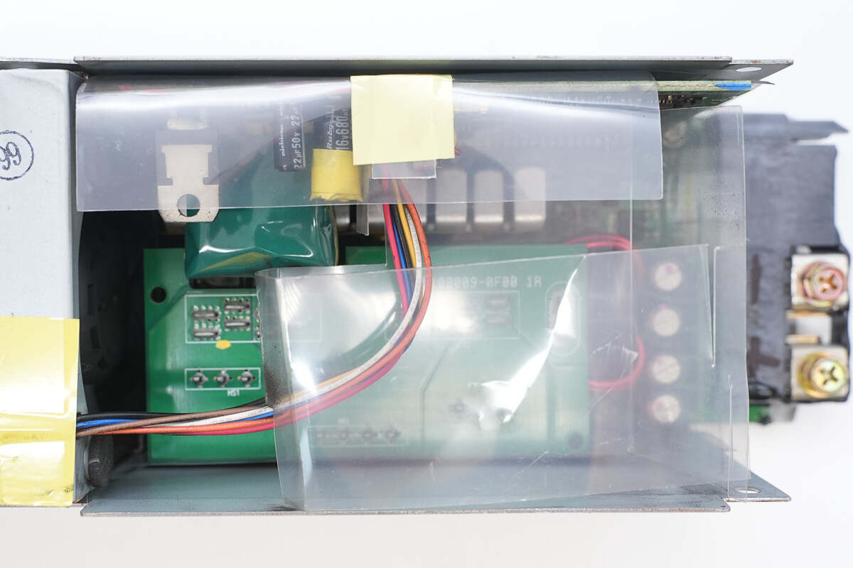
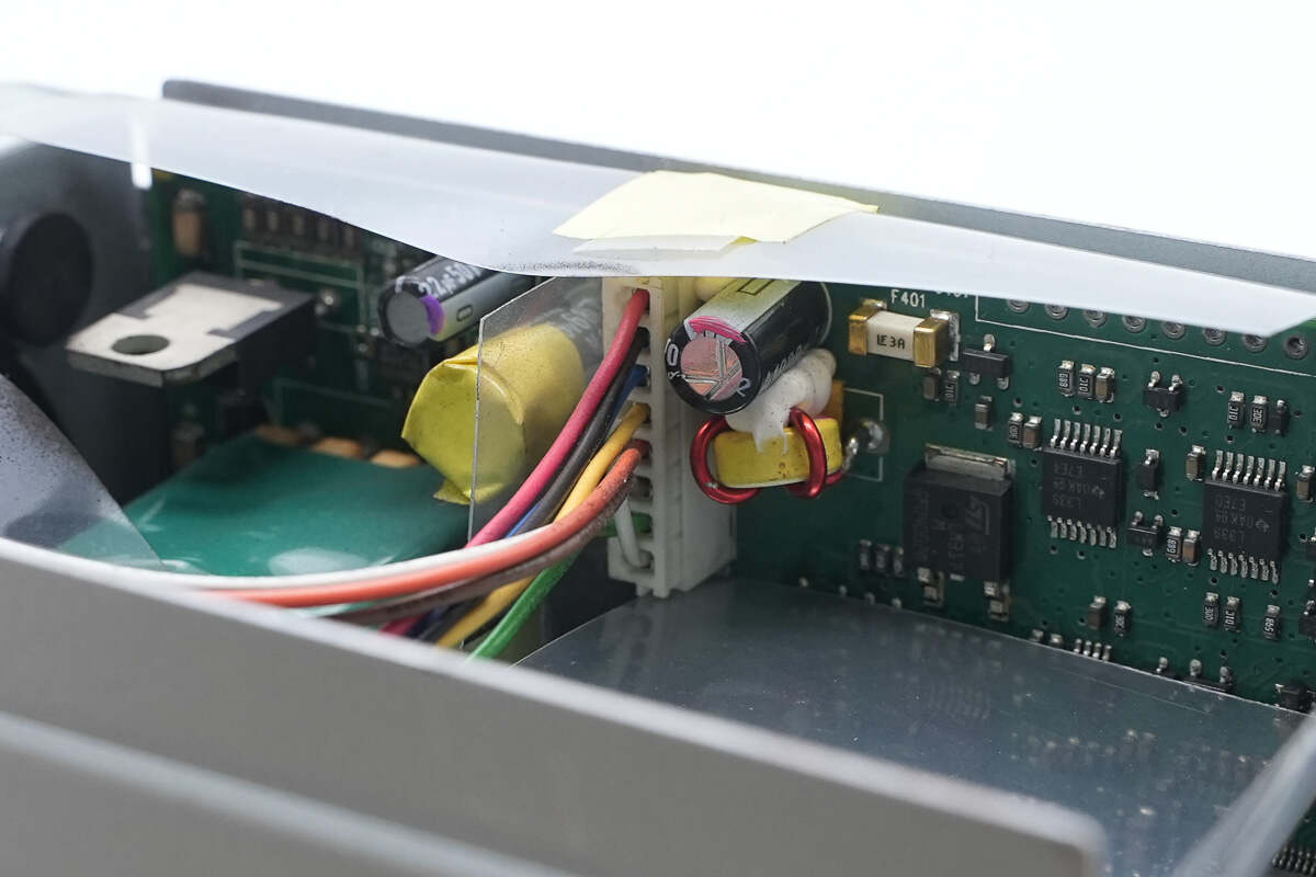
On the right side of the auxiliary power PCB are the primary MOSFET and the power chip. The transformer is located in the middle, while the left side houses a synchronous rectifier and filter capacitors.
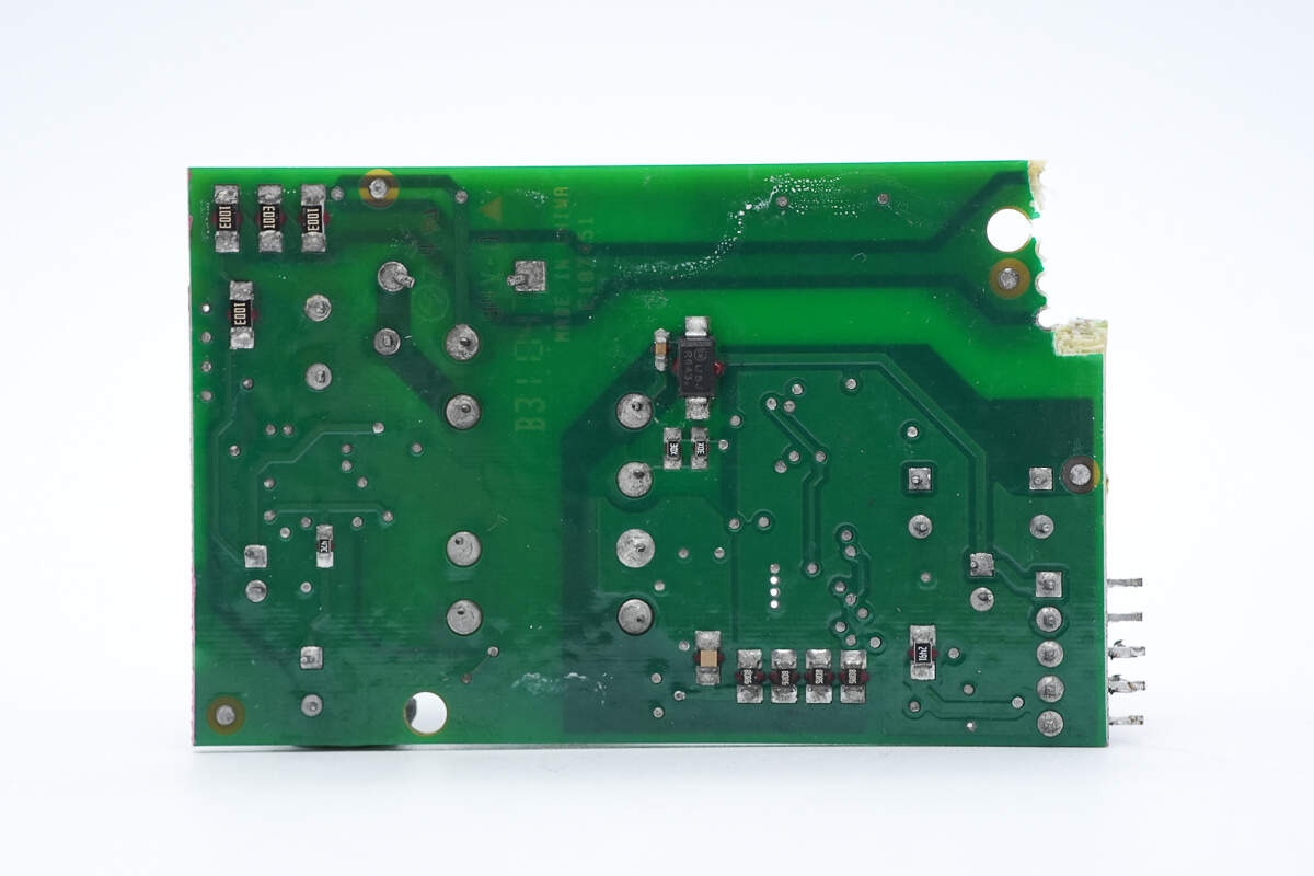
On the backside, there are rectifier diodes and current-sense resistors.
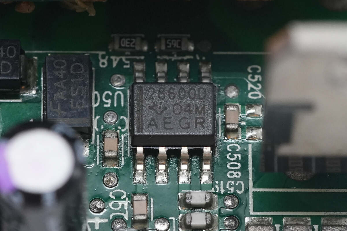
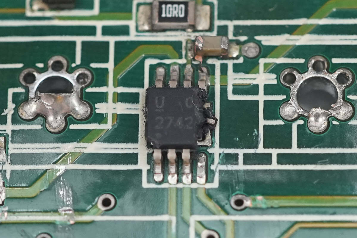
The primary controller IC is from TI, model UCC28600. It is a quasi-resonant flyback controller featuring an eco-friendly green mode and comes in an SOIC-8 package.
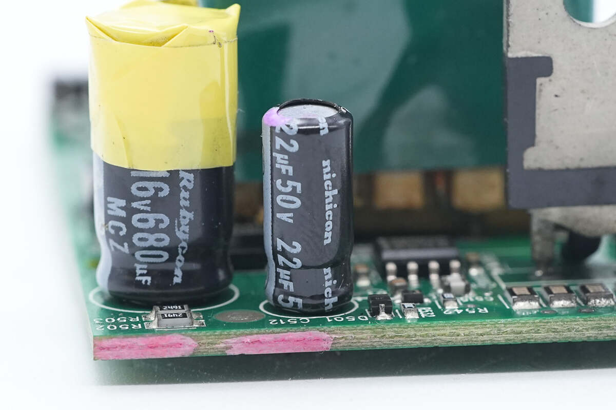
The filter capacitor for the primary controller IC is from Nichicon, with a specification of 22μF 50V.
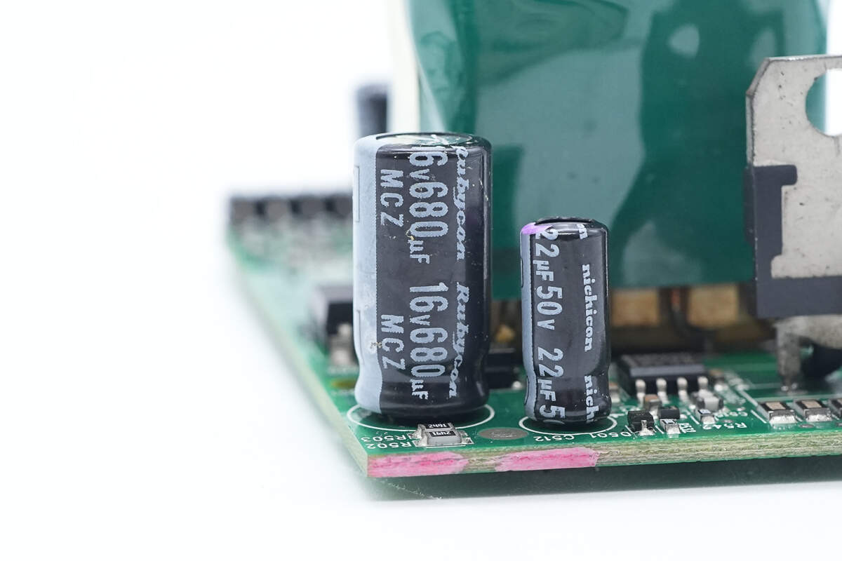
The other filter capacitor is from Rubycon, with a specification of 680μF 16V.
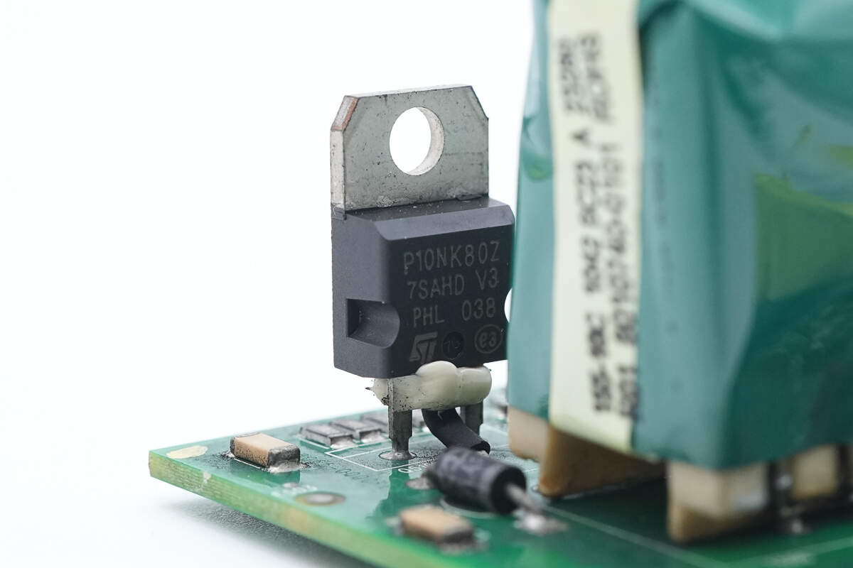
The auxiliary power MOSFET is from STMicroelectronics, model STP10NK80Z. It is an N-channel MOSFET with a voltage rating of 800V and an on-resistance of 780mΩ, housed in a TO-220 package.
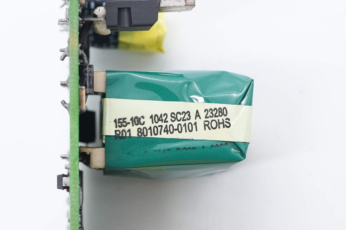
The transformer is insulated with adhesive tape.
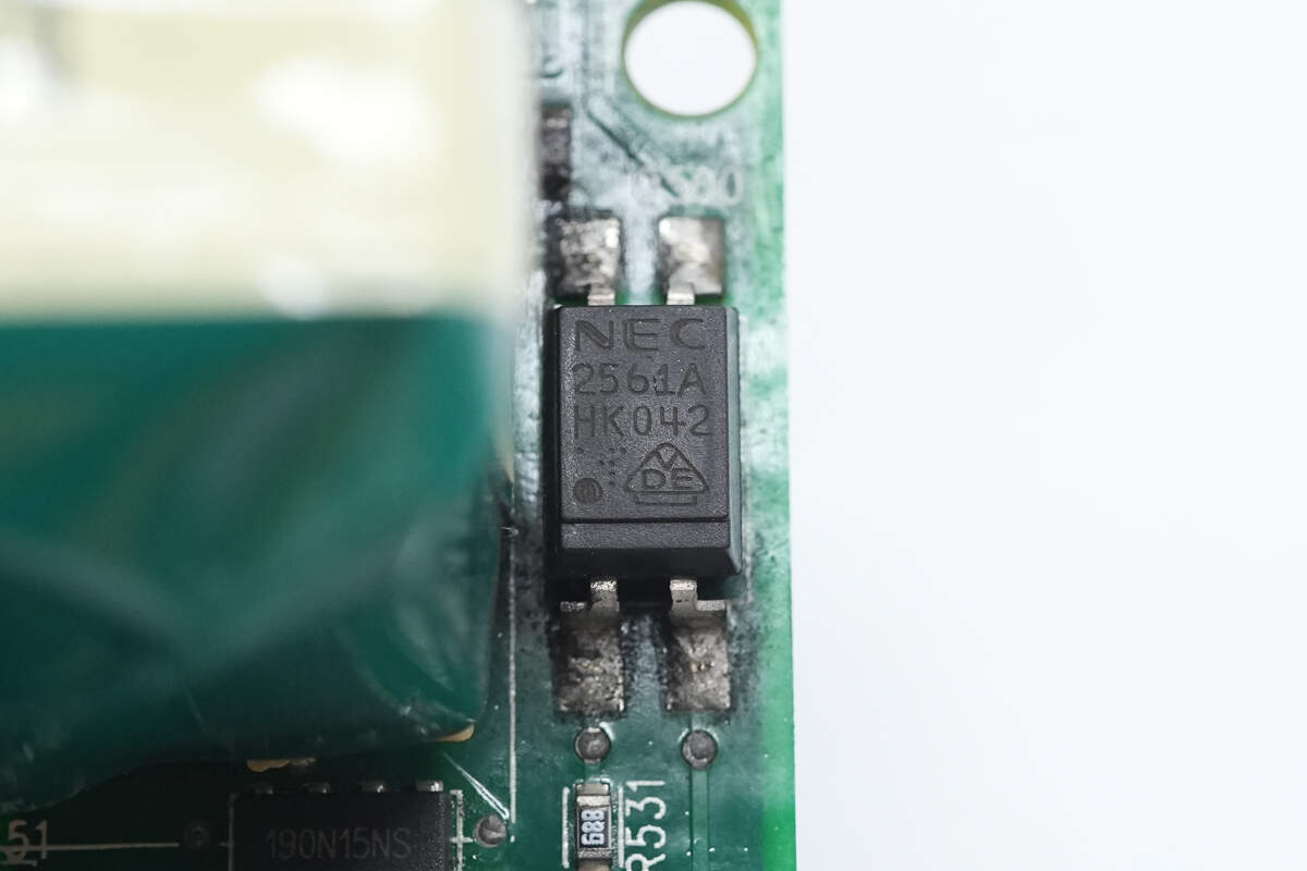
The NEC 2561A optocoupler is used for output voltage feedback.
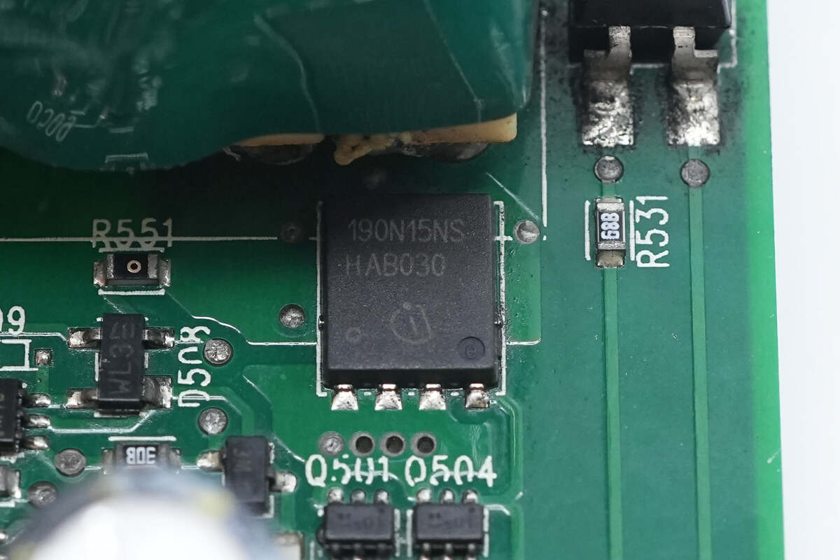
The synchronous rectifier is from Infineon, model BSC190N15NS3 G. It is an N-channel MOSFET with a voltage rating of 150V and an on-resistance of 19mΩ, housed in a TDSON-8 package.
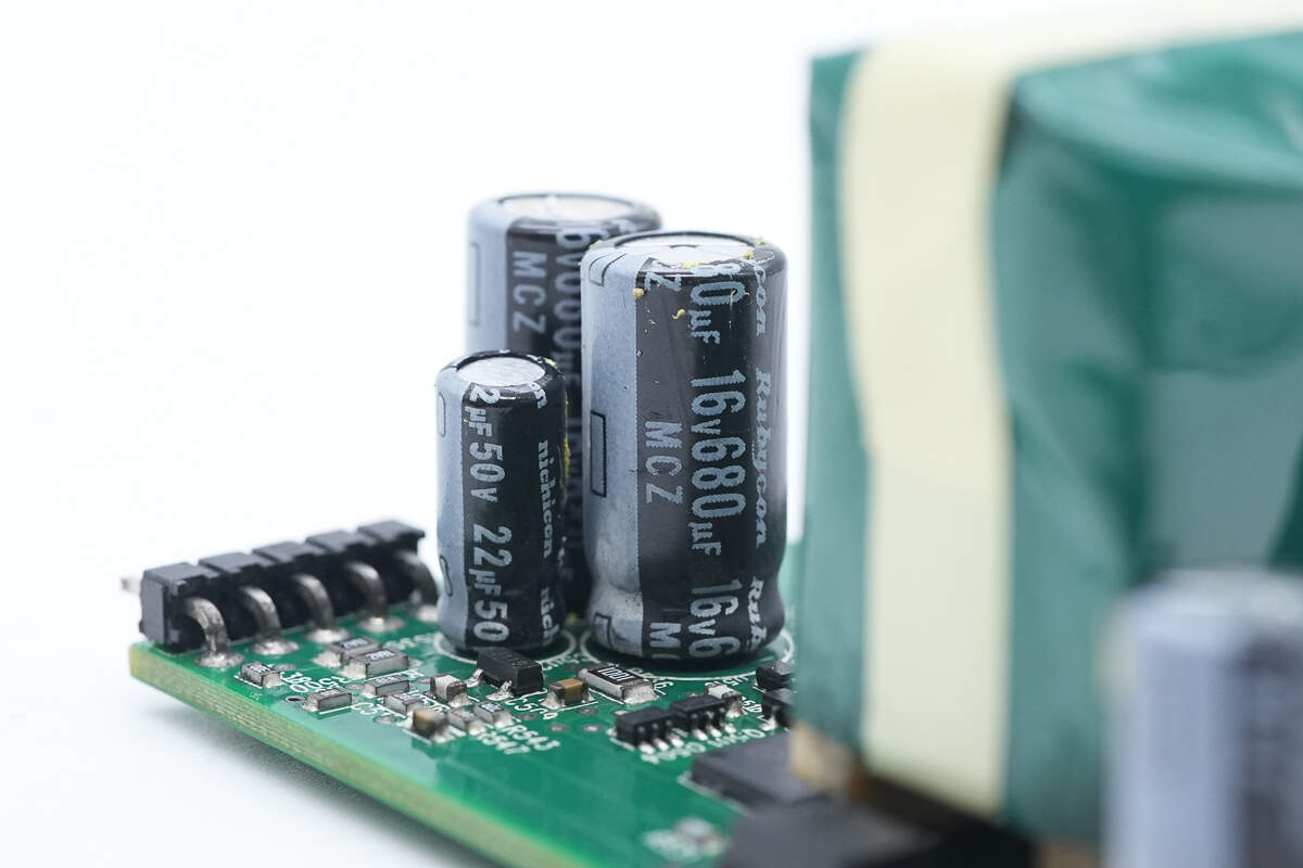
The filter capacitor is from Rubycon, with a specification of 680μF 16V.
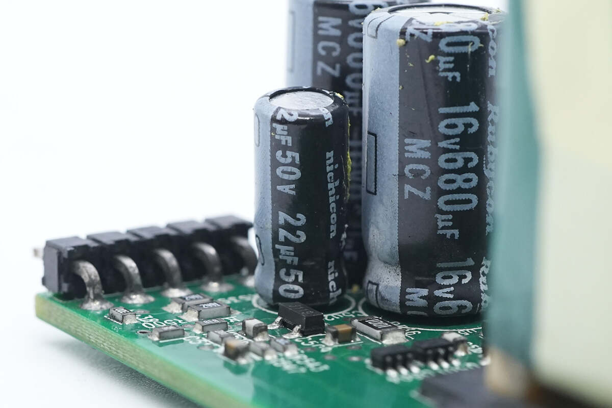
The filter capacitor is from Nichicon, with a specification of 22μF 50V.
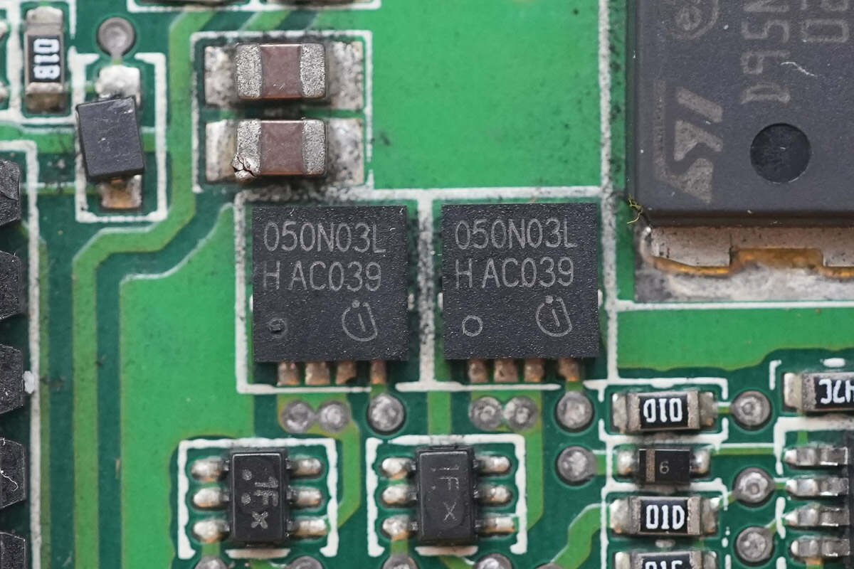
The MOSFETs used for power control are from Infineon, model BSC050N03LS G. They are N-channel MOSFETs with a voltage rating of 30V and an on-resistance of 5mΩ, housed in an SO-8 package.
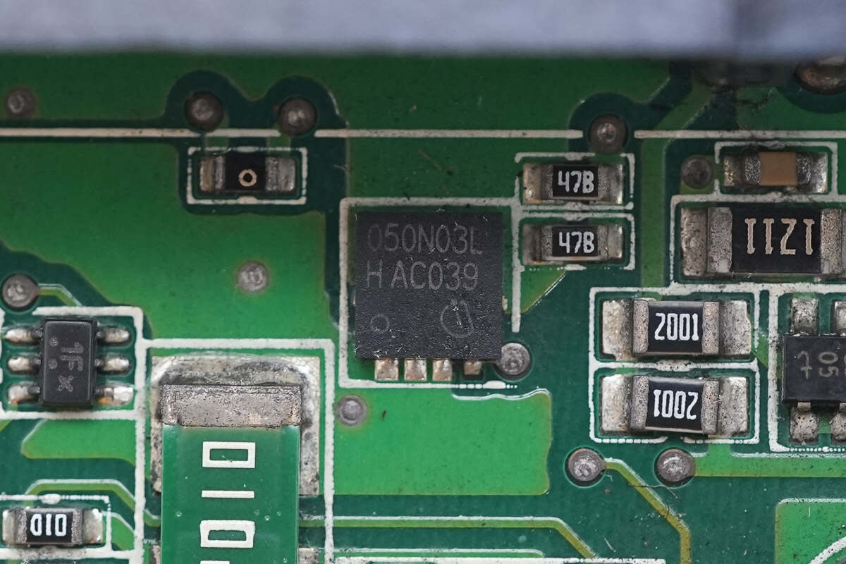
The other MOSFET has the same model.
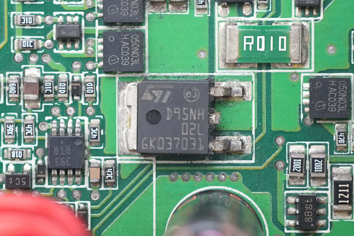
The MOSFET used for power control is from STMicroelectronics, model STD95NH02L. It is an N-channel MOSFET with a voltage rating of 24V and an on-resistance of 3.9mΩ, housed in a DPAK package.
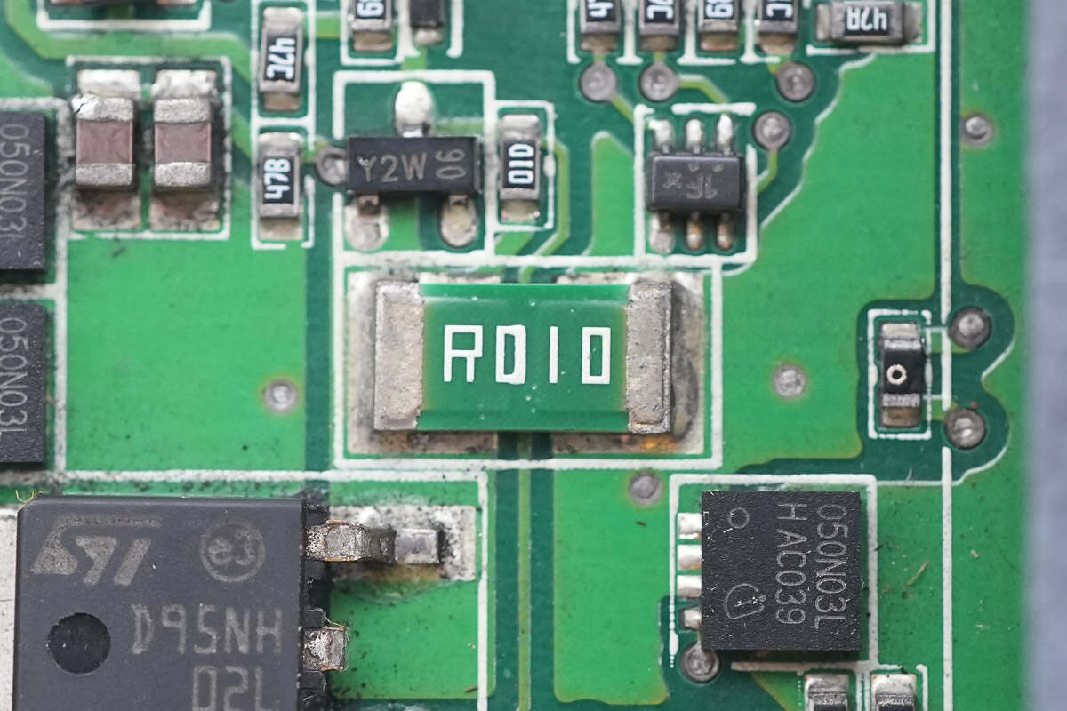
Close-up of the 10mΩ current sense resistor.
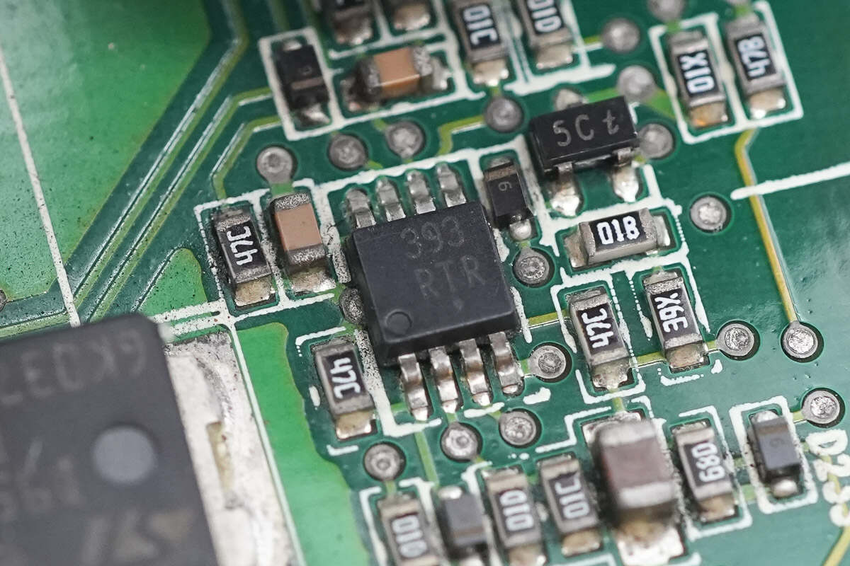
Close-up of the dual 393 voltage comparator.
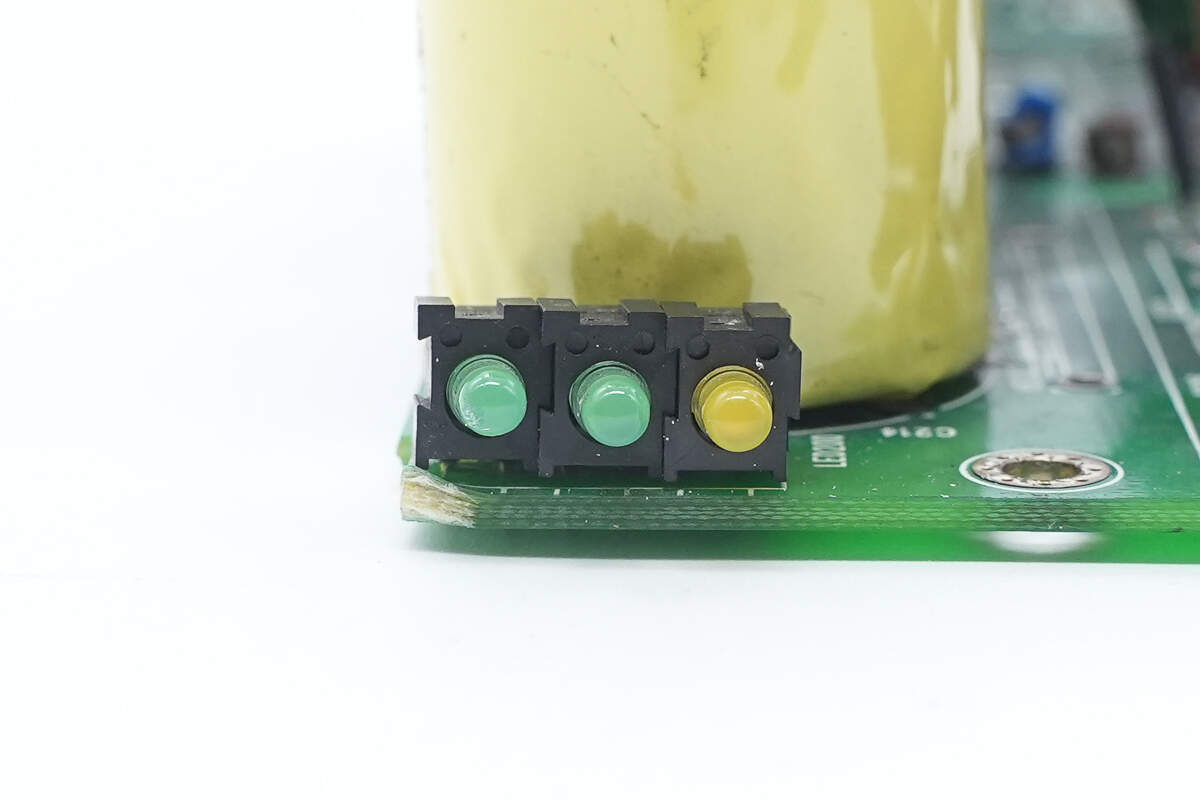
Close-up of the LED indicators at the input end.

Well, those are all components of the EMERSON 1725W AC Power Supply.
Summary of ChargerLAB
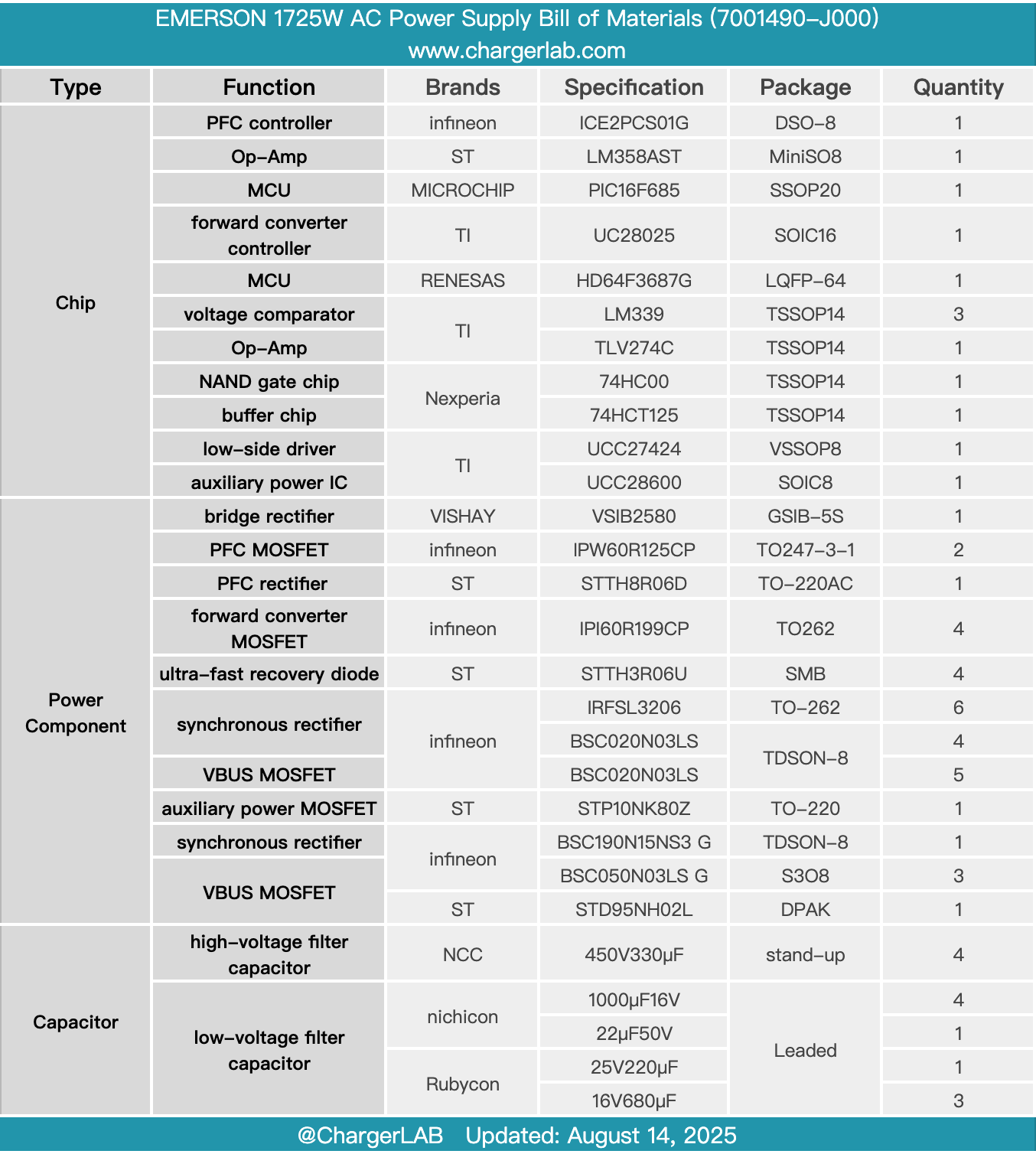
Here is the component list of the EMERSON 1725W AC Power Supply for your convenience.
It supports a wide input voltage range of 100-240V, with an output voltage of 12.3V and a rated output power of 1725W. The input side features a C14 power inlet, indicator LEDs, and a latch handle, while the output side is equipped with power connectors. Inside, there is a cooling fan, and both ends have ventilation holes for airflow.
After taking it apart, we found that it uses a PFC plus forward converter architecture. The PFC controller is an Infineon ICE2PCS01G, paired with Infineon IPW60R125CP MOSFETs and a STMicro STTH8R06D rectifier. The forward converter is controlled by a TI UC28025 controller, working with Infineon IPI60R199CP MOSFETs and IRFSL3206 synchronous rectifiers.
A cooling fan is installed at the center of the module, with the PFC circuit and forward converter circuit positioned on either side. Inside, there are control and auxiliary power PCBs, featuring Microchip and Renesas MCUs for voltage, current, and power measurement. All filter capacitors are sourced from reputable Japanese brands, and power devices use top-tier international brands. Synchronous rectifiers are soldered directly onto the copper plate to enhance heat dissipation. The power supply is solidly built with reliable components.
Related Articles:
1. Teardown of Foton Aumark 3kW DC-DC Converter (SDM302BUYM)
2. Teardown of UGREEN Nexode 20000mAh 130W Power Bank with Built-in USB-C Cable (PB723)
3. Teardown of Supermicro 720W 1U Redundant Power Supply (PWS-721P-1R)