Introduction
We’re taking apart the EcoFlow RAPID 170W Power Bank with built-in cables. This device features a 16-bit color TFT display that shows real-time feedback, including power status, port usage, output wattage, and animated icons.
It comes with two integrated USB-C cables, an additional lanyard-style USB-C cable, one USB-A port, and one USB-C port, allowing up to four devices to charge simultaneously. The total output can reach up to 170W, and the USB-C1, C2, and C3 ports all support 100W bidirectional fast charging. Performance is strong across the board. Now let’s take a closer look at the internal design and hardware layout of this product.
Product Appearance
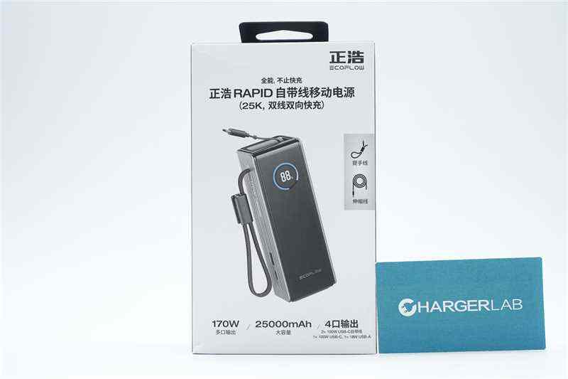
The front of the package features the EcoFlow logo, the product name, an image of the device, and key specifications and selling points.
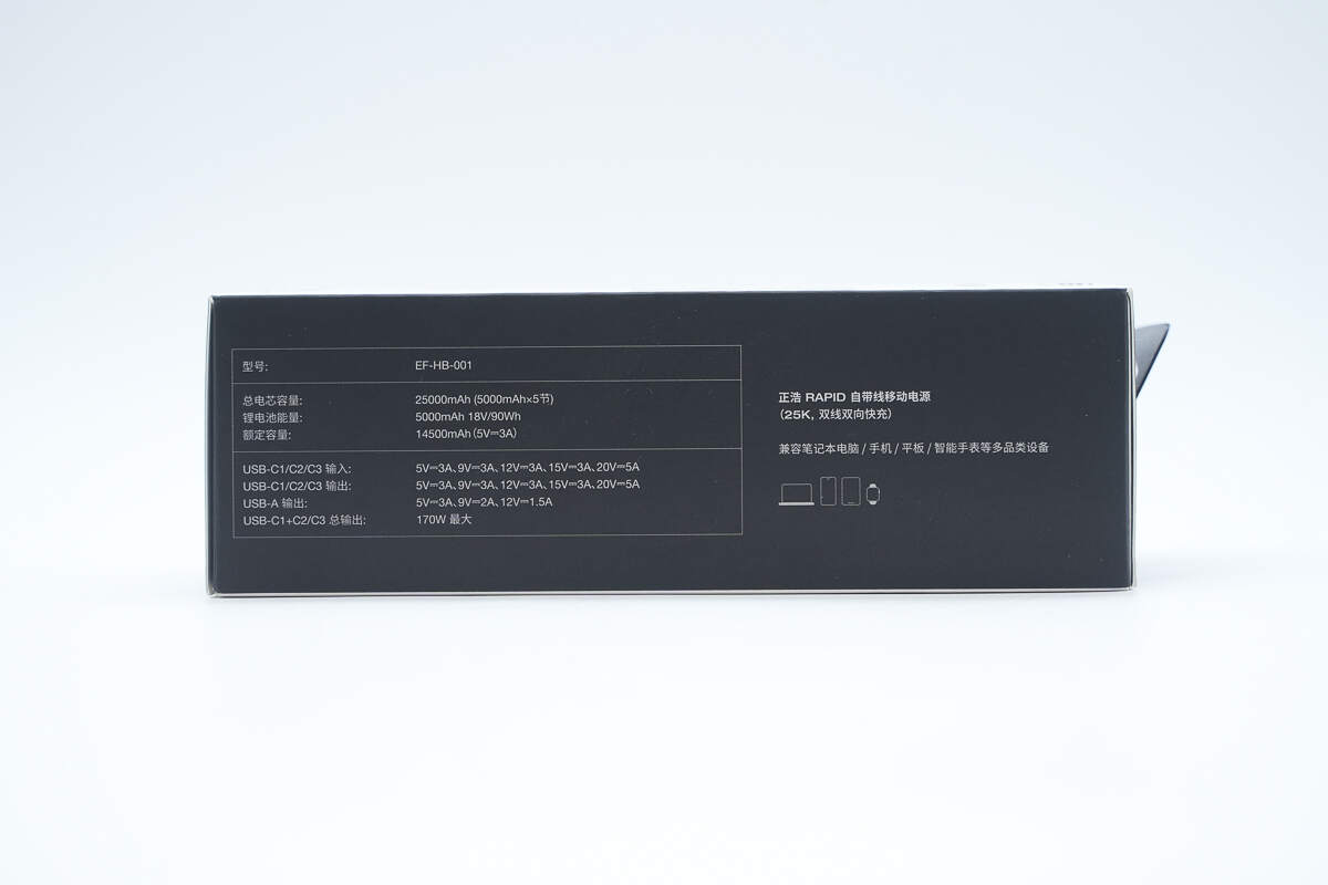
The side of the package lists the product specifications and indicates compatibility with a wide range of devices, including laptops, smartphones, tablets, and smartwatches.

The back is printed with the usage scenarios and key selling points.
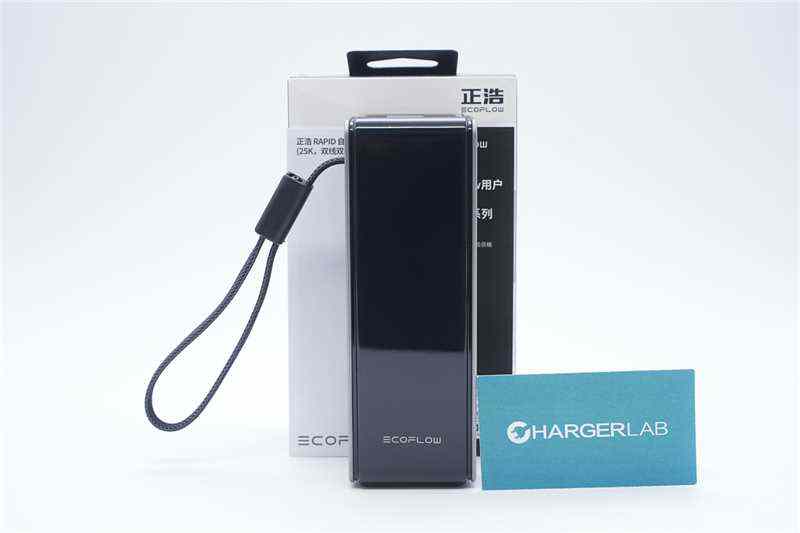
The package includes the power bank, instruction manual, etc.
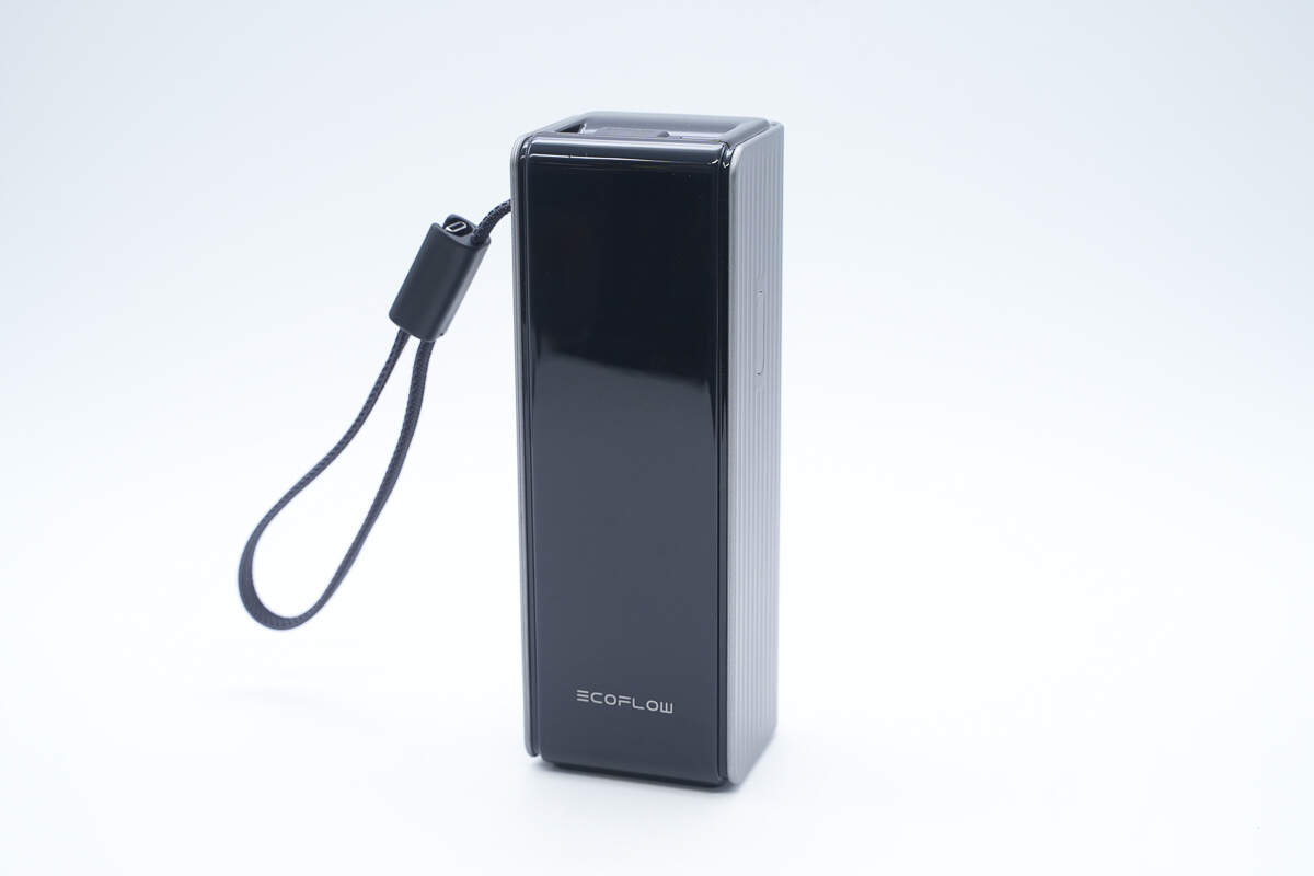
The design has a strong sense of style and modern aesthetics.

The upper front of the device features a hidden 16-bit color TFT display, while the EcoFlow logo is printed below it.
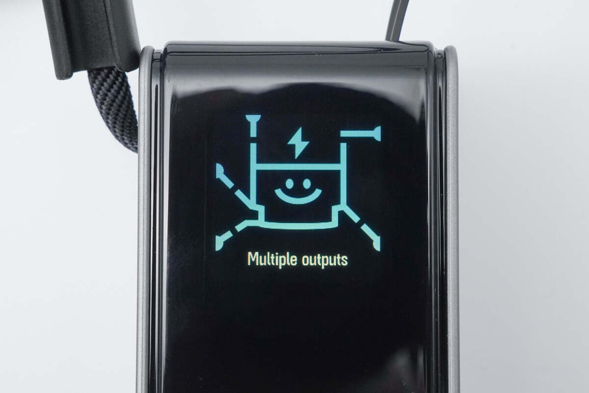
The display offers a rich interface with various functions, as shown in the image, and also supports fun animated icons.
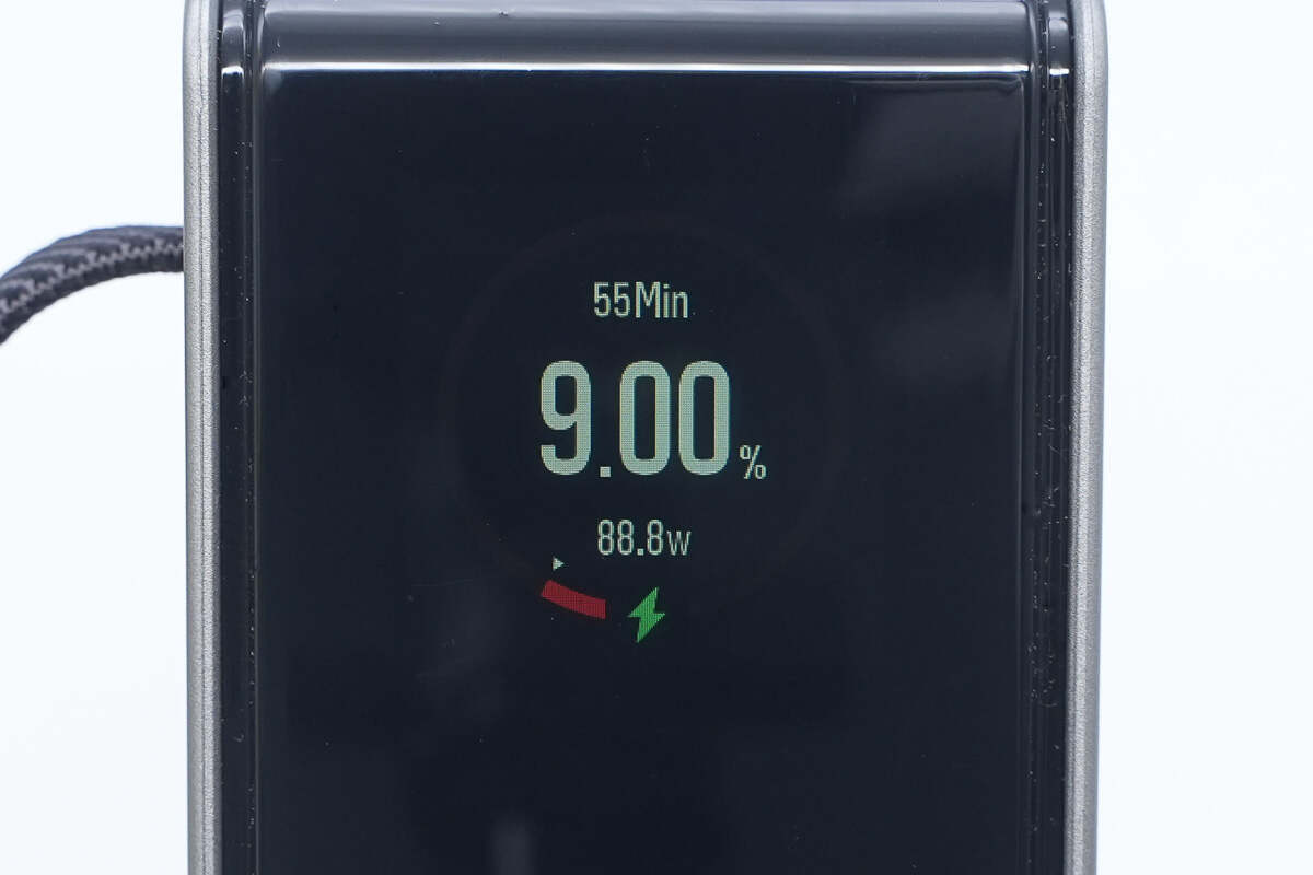
The display shows the remaining battery level, input charging power, and estimated time to full charge. The input charging is indicated by a green lightning bolt icon.
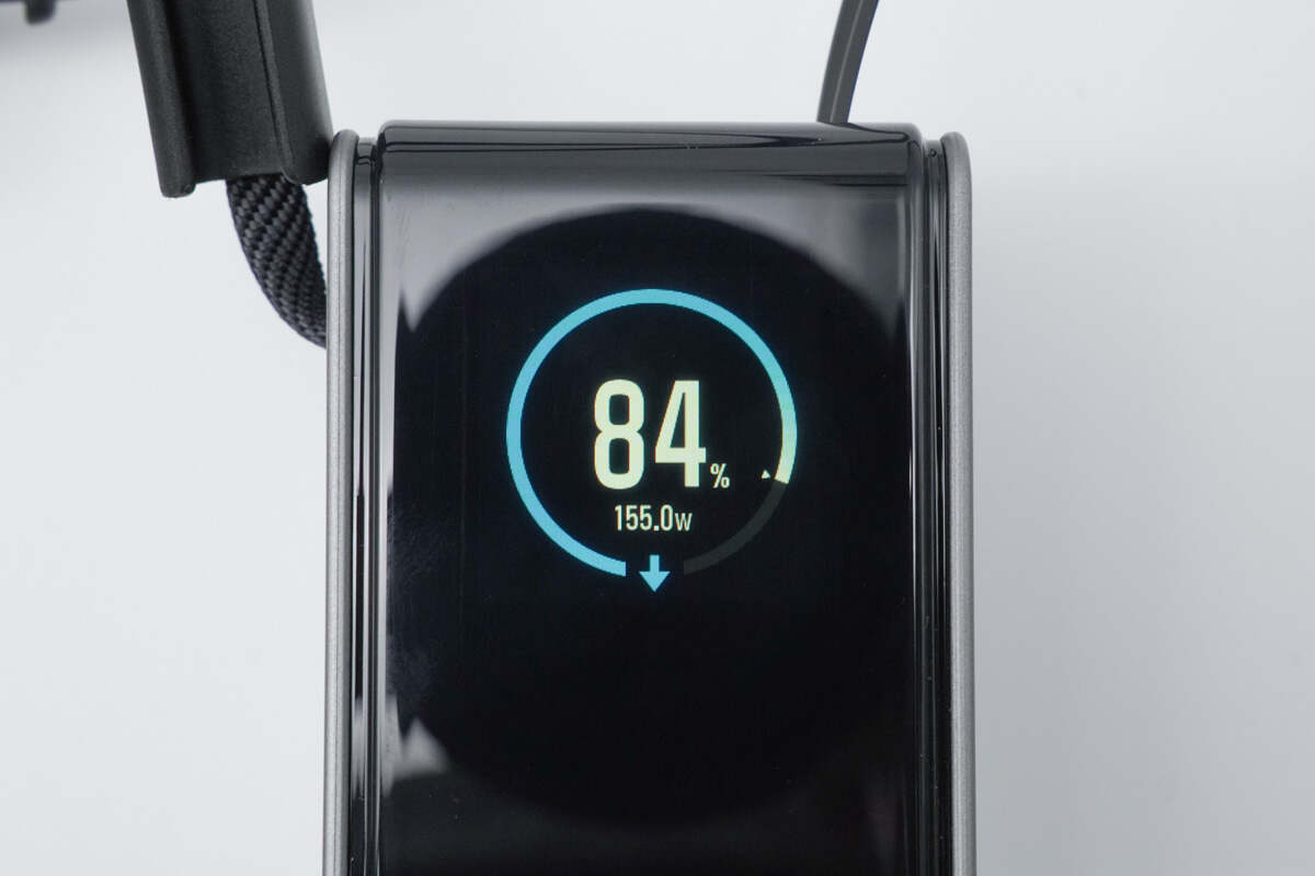
When outputting power, a blue downward arrow is shown, along with the total output power.
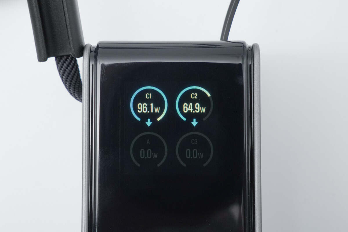
The status of each port, along with real-time input and output power, is also clearly displayed at a glance.

It also features battery health and temperature monitoring on the display.
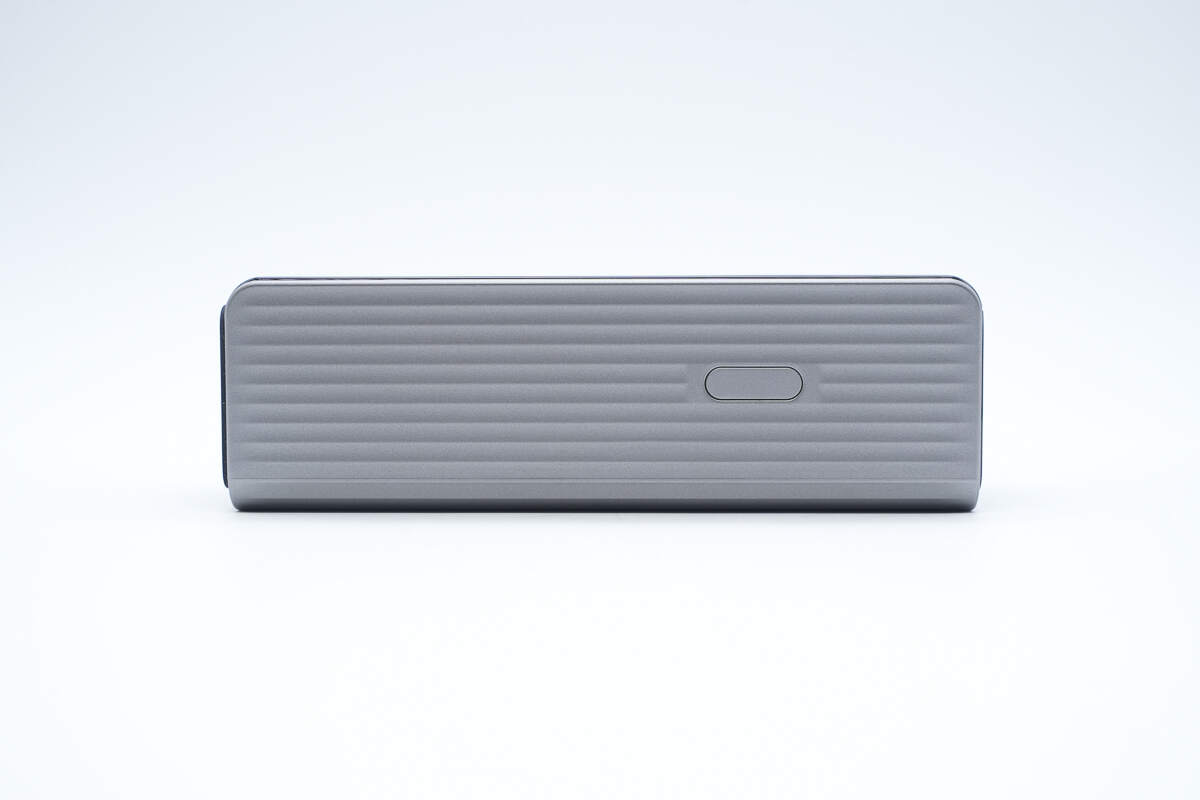
The sides of the device are designed with anti-slip textured patterns.
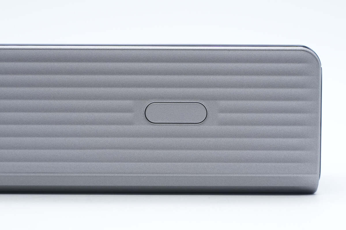
The power button is located on the side of the device.
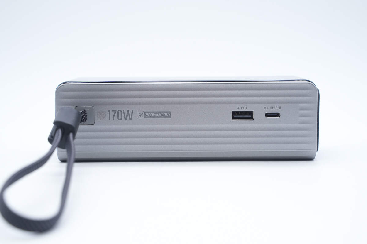
On the other side, there is one USB-A port, one USB-C port, and the USB-C2 lanyard cable. The casing is marked with “170W,” “25,000mAh / 90Wh,” and an airplane-approved symbol.
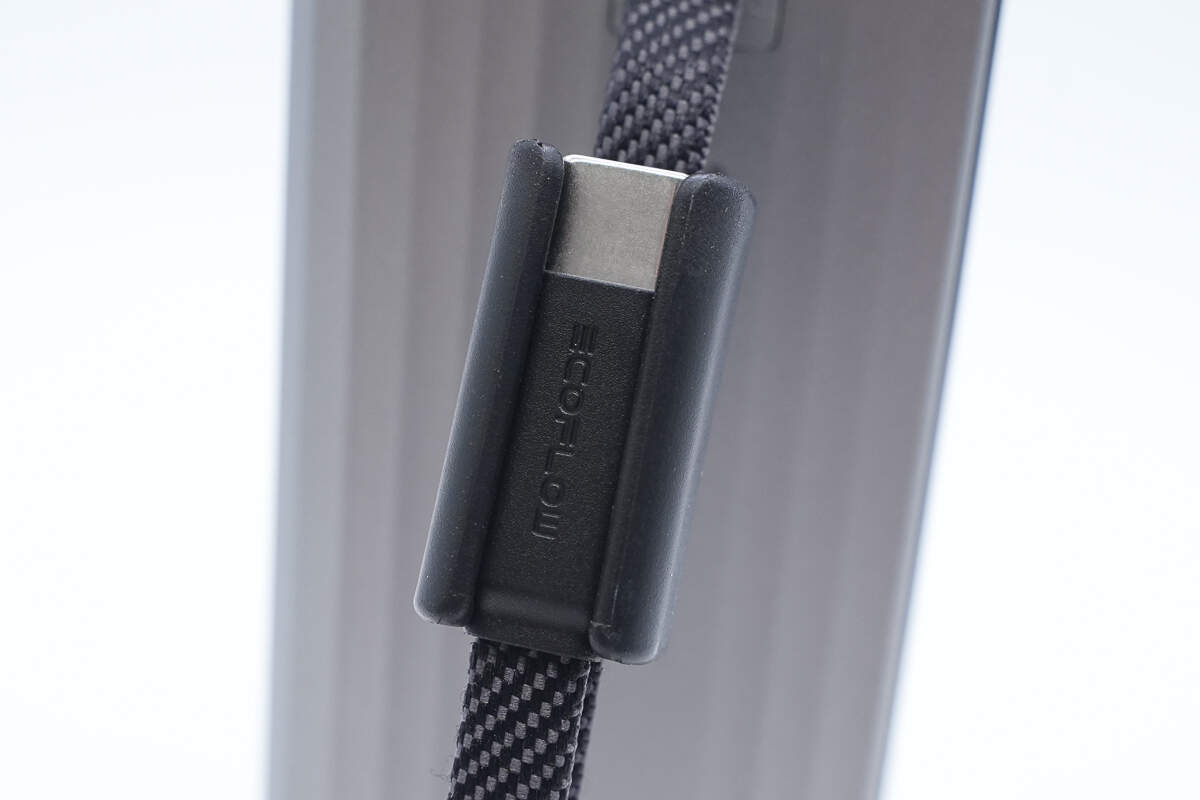
The USB-C2 lanyard cable features an integrated terminal storage and securing design, allowing it to be carried, hung, or used for charging conveniently.
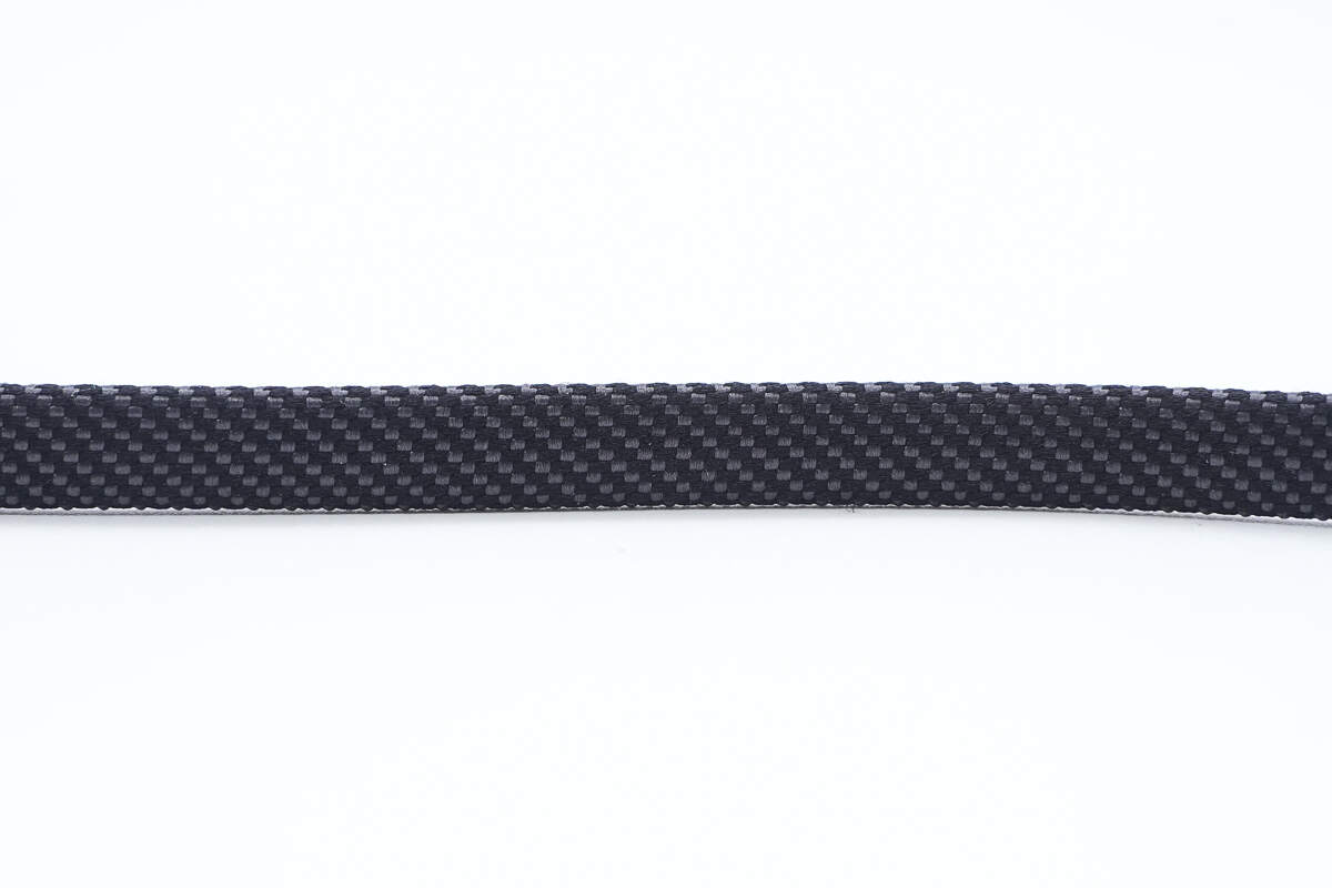
The cable is made of braided material.

The connector housing has a matte finish with the EcoFlow logo engraved on the front.

The top of the device features a retractable USB-C1 cable.
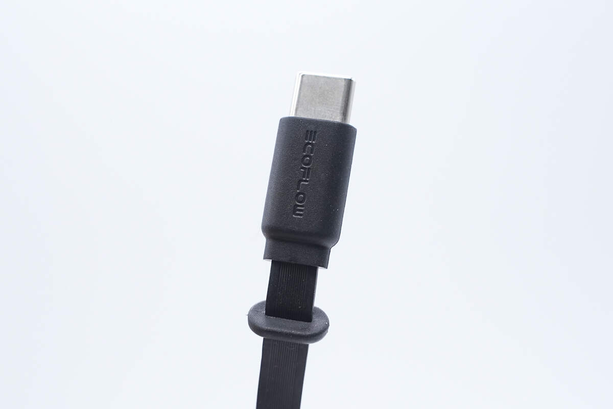
The retractable cable’s connector also has a matte finish with the EcoFlow logo engraved on it.
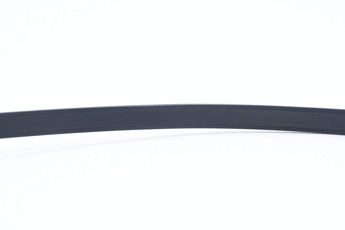
The retractable cable is flat and made of silicone material.
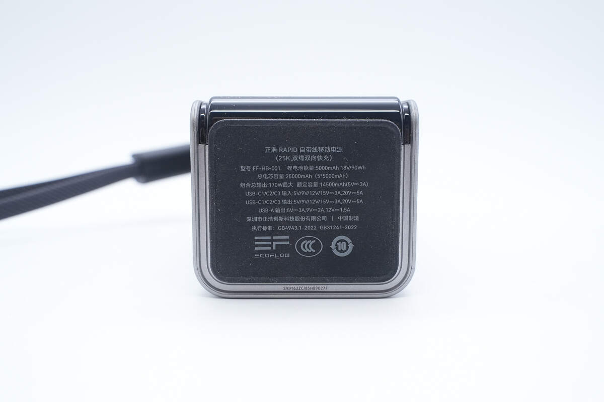
The bottom is equipped with an anti-slip pad and printed with specification information.
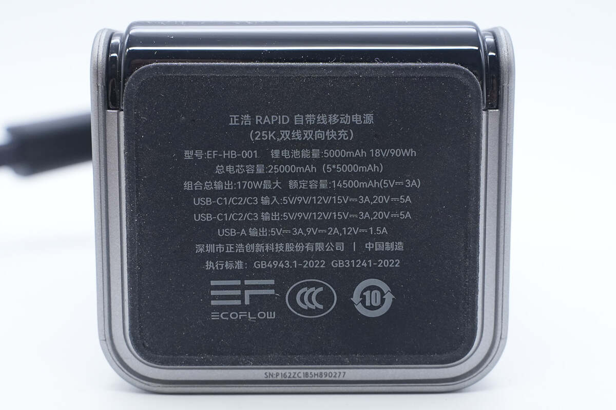
Model: EF-HB-001
Lithium Battery Energy: 5000mAh 18V / 90Wh
Total Cell Capacity: 25,000mAh (5 × 5000mAh)
Maximum Combined Output: 170W Max
Rated Capacity: 14,500mAh (5V 3A)
USB-C1/C2/C3 Input: 5V / 9V / 12V / 15V 3A, 20V 5A
USB-C1/C2/C3 Output: 5V / 9V / 12V / 15V 3A, 20V 5A
USB-A Output: 5V 3A, 9V 2A, 12V 1.5A
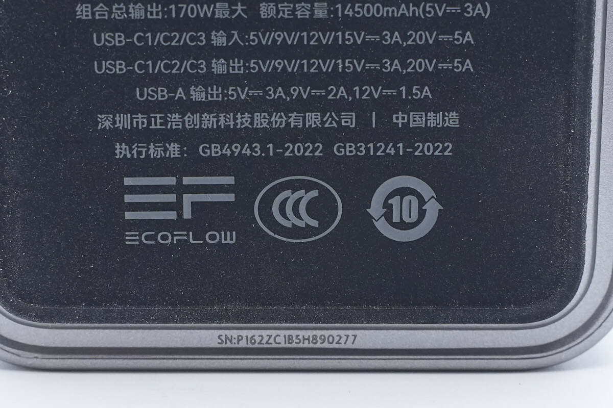
It has passed the CCC certification.

The length of the power bank is about 157.04 mm (6.18 inches).
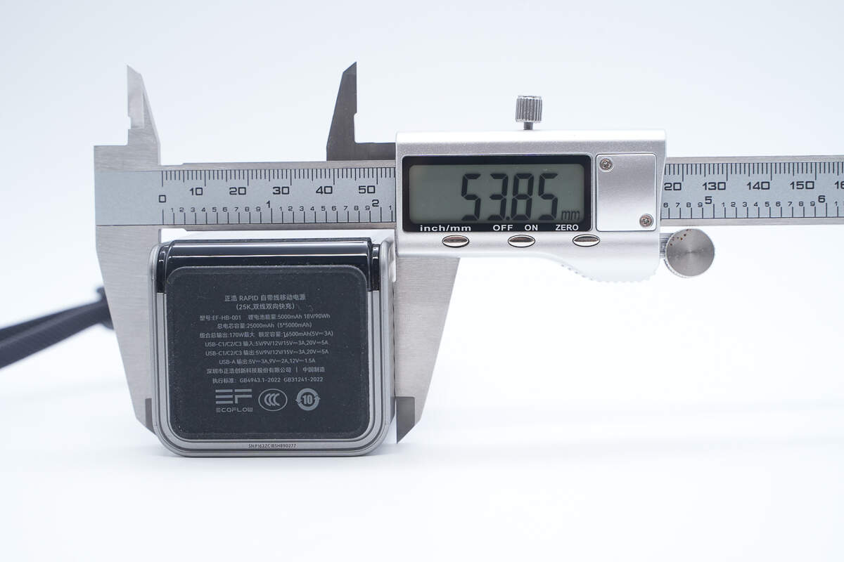
The width is about 53.85 mm (2.12 inches).
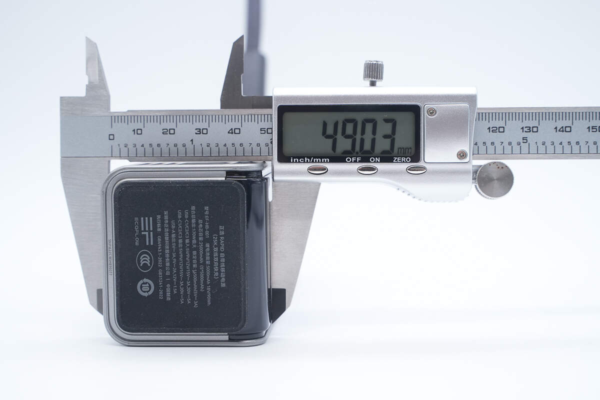
The thickness is about 49.03 mm (1.93 inches).

The length of the retractable USB-C1 cable is about 64.5 cm (25.39 inches).
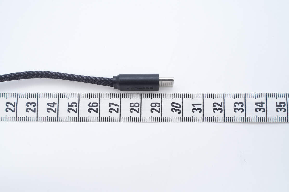
The length of the USB-C2 lanyard cable is about 29.5 cm (11.61 inches).
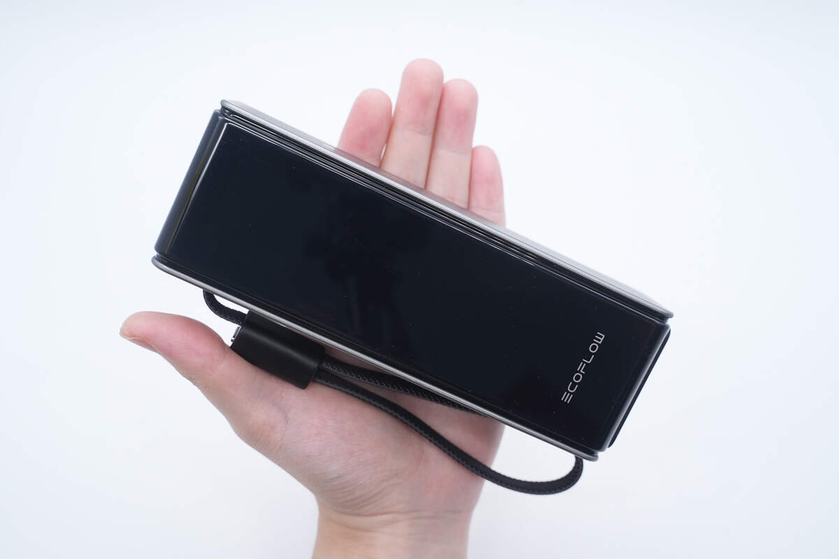
That's how big it is in the hand.
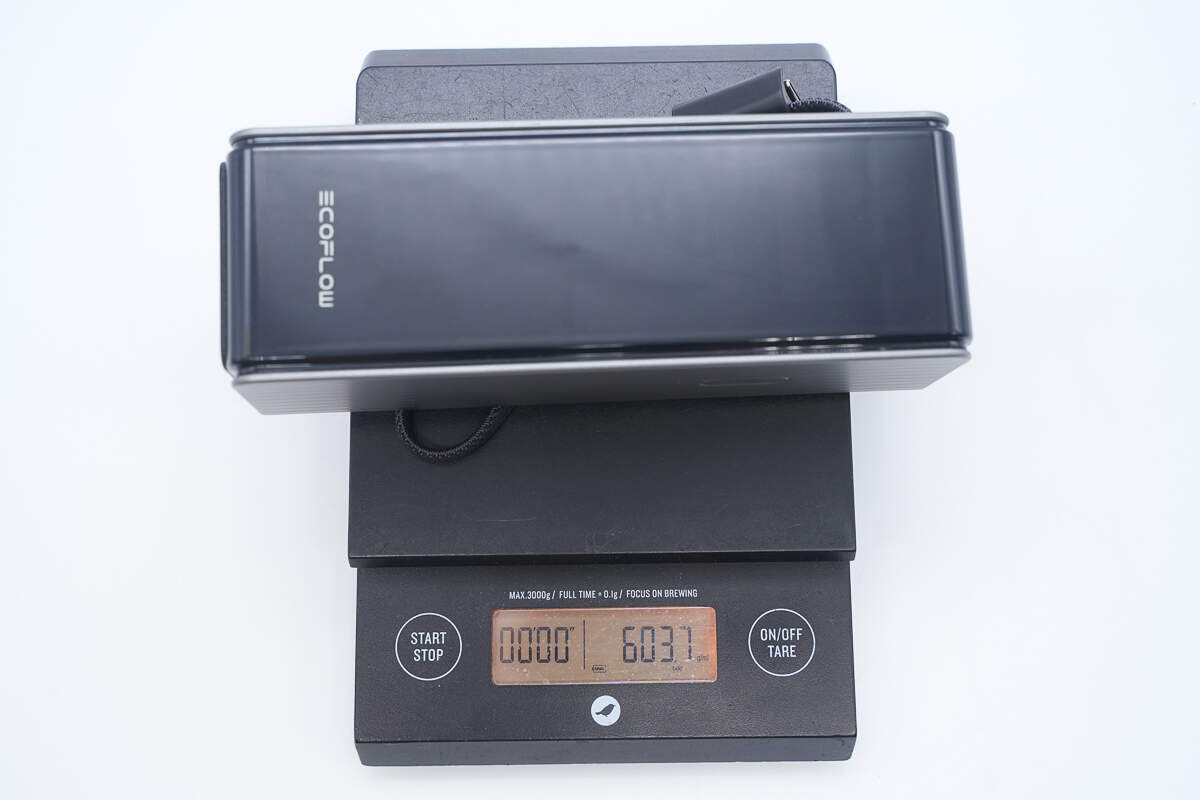
The weight is about 604 g (21.31 oz).

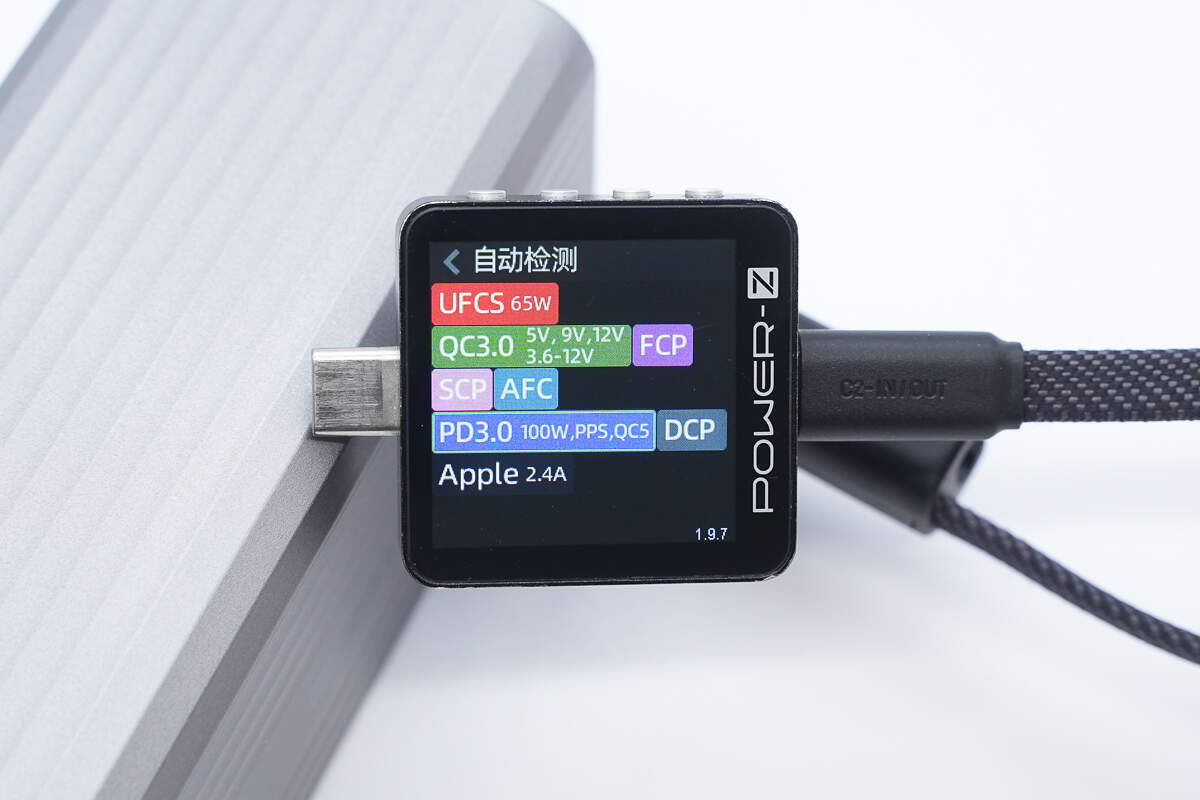
ChargerLAB POWER-Z KM003C shows that the retractable USB-C1 cable supports UFCS, QC3.0/5, FCP, SCP, AFC, PD3.0, PPS, DCP, and Apple 2.4 charging protocols.

And it has five fixed PDOs of 5V3A, 9V3A, 12V3A, 15V3A, and 20V5A. It has one set of PPS, which is 5-21V5A.
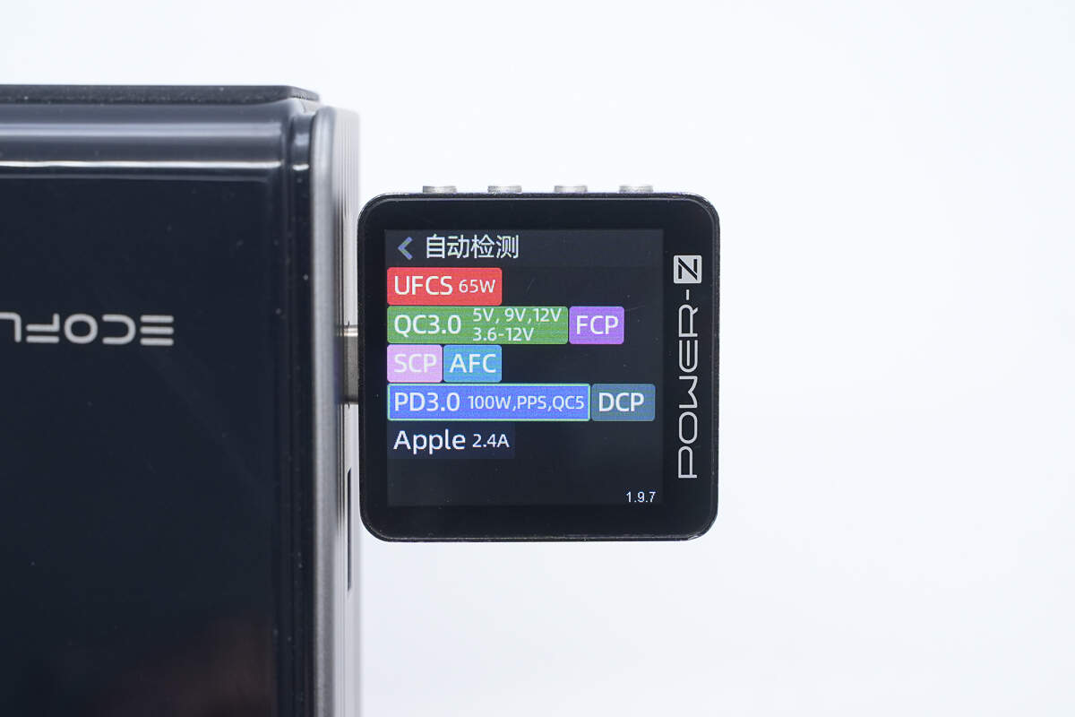
Testing shows that the USB-C2 lanyard cable supports the same protocols as the USB-C1 retractable cable.

The PDO messages are also identical.
Testing confirms that the USB-C3 port supports the same protocols as the two cables.

The PDO messages are also the same, meaning all three USB-C ports deliver identical output performance.
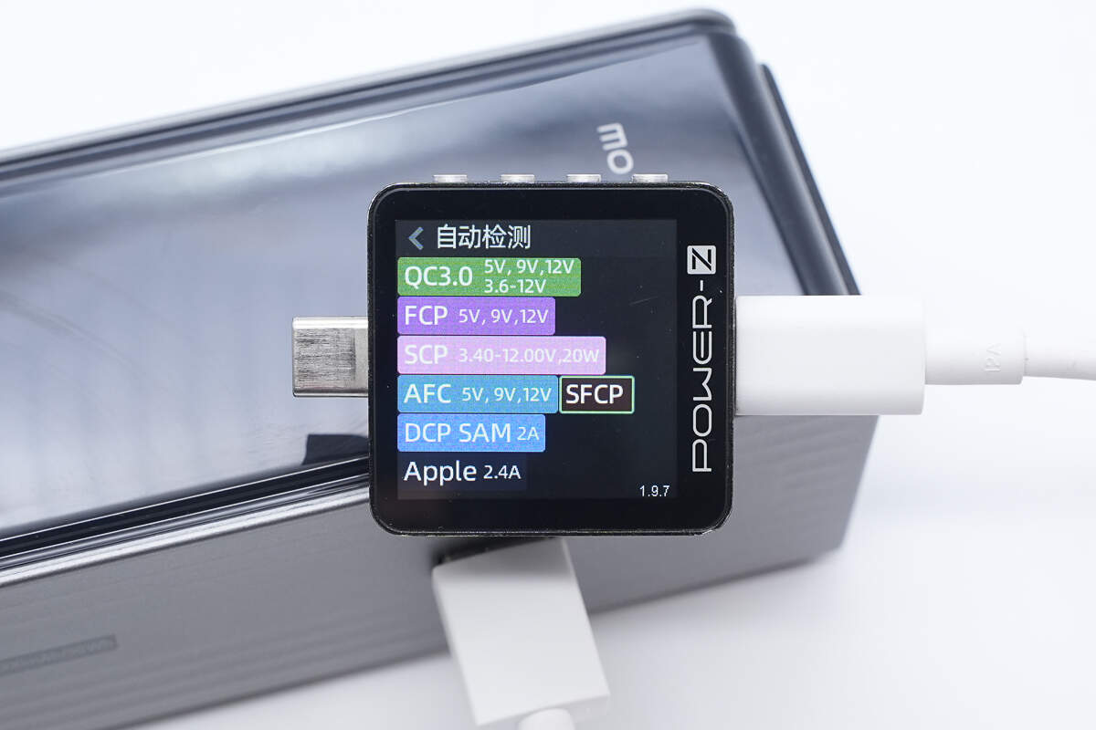
The USB-C cable supports QC3.0, FCP, SCP, AFC, SFCP, DCP, SAM 2A, and Apple 2.4 charging protocols.
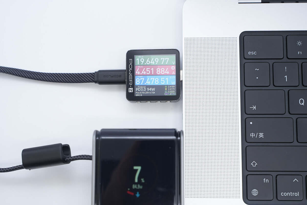
When using the USB-C2 to charge the MacBook Pro, the power is about 87.48W, successfully activating 20V5A 100W PD fast charging.

When charging the power bank via the USB-C3 port, the input power measured approximately 90.04W, successfully activating 100W PD fast charging.
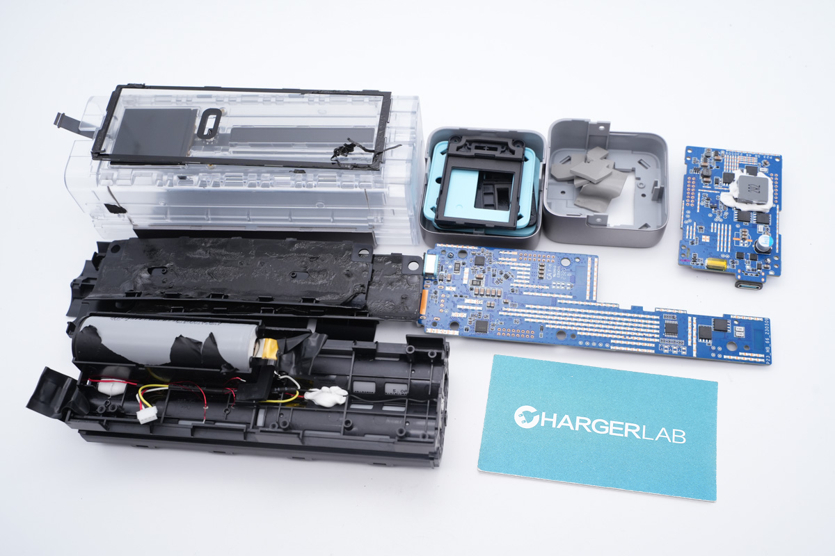
Teardown
Next, let's take it apart to see its internal components and structure.

The front panel is secured with snap-fit clips along the edges and can be removed by carefully prying it off.
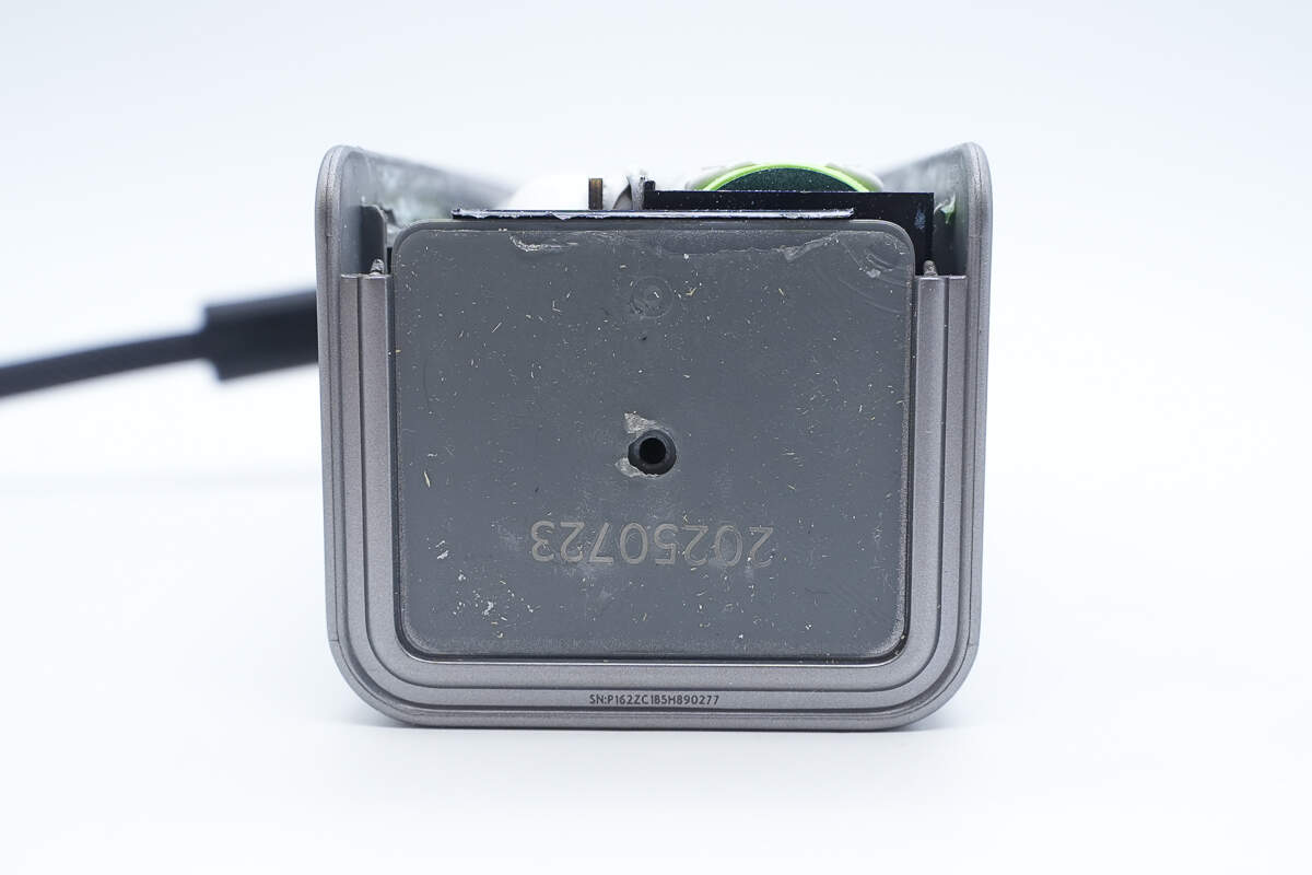
Peel off the anti-slip pad at the bottom to reveal a hidden screw in the center (which has already been removed).
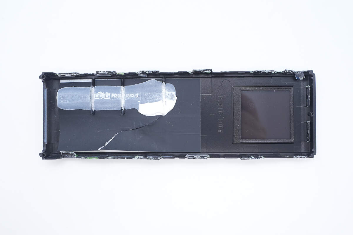
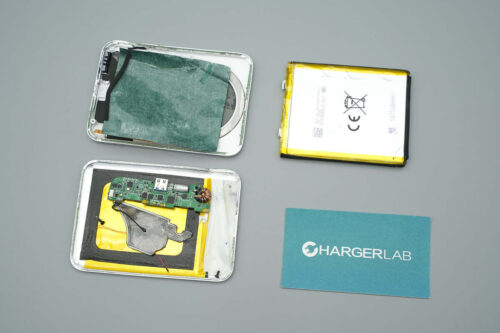
The inside of the front panel is lined with protective foam for insulation, and the edges of the display are cushioned with foam padding.
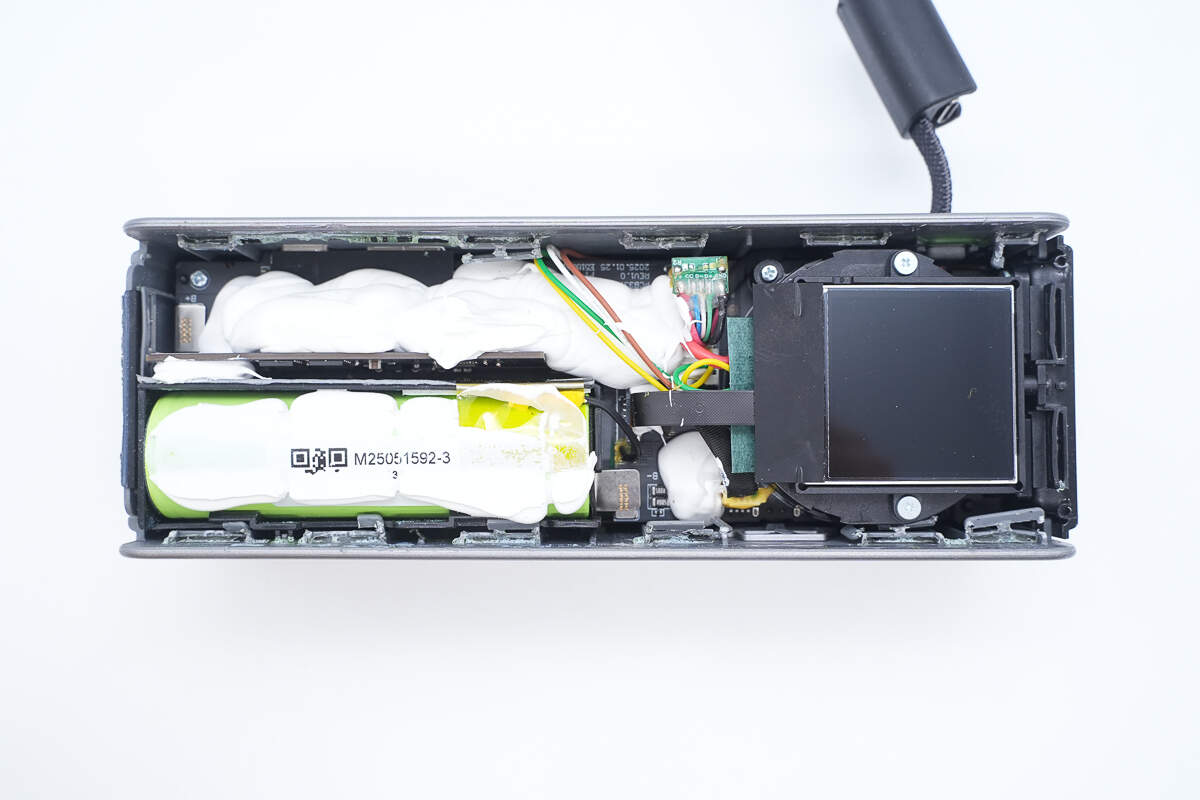
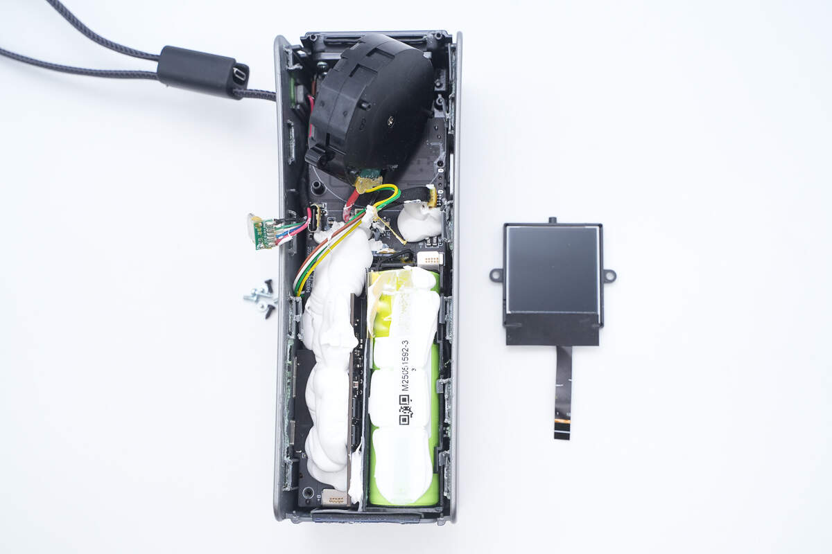
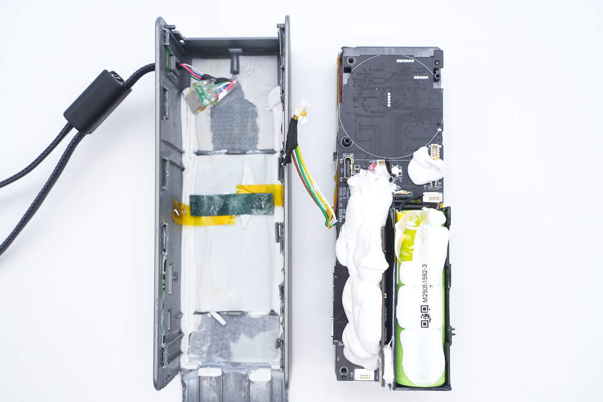
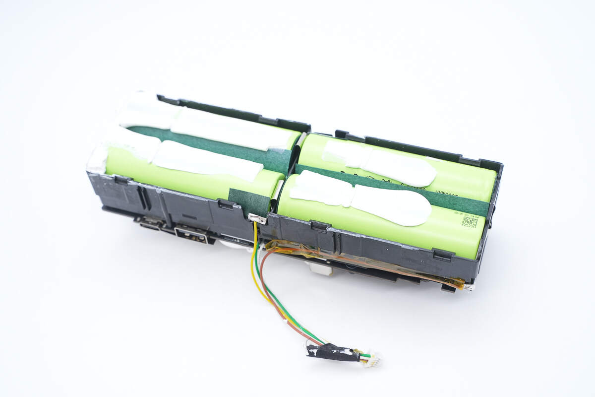
Inside, the upper layer contains a single battery cell, next to which a small vertical PCB is soldered. The display is located on the right side.
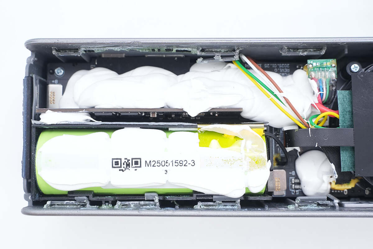
The area around the battery cell and PCB is heavily reinforced and secured with white adhesive. A thermistor is attached to the right end of the battery cell for temperature monitoring.
The single battery cell is spot-welded to the main PCB using a nickel strip.
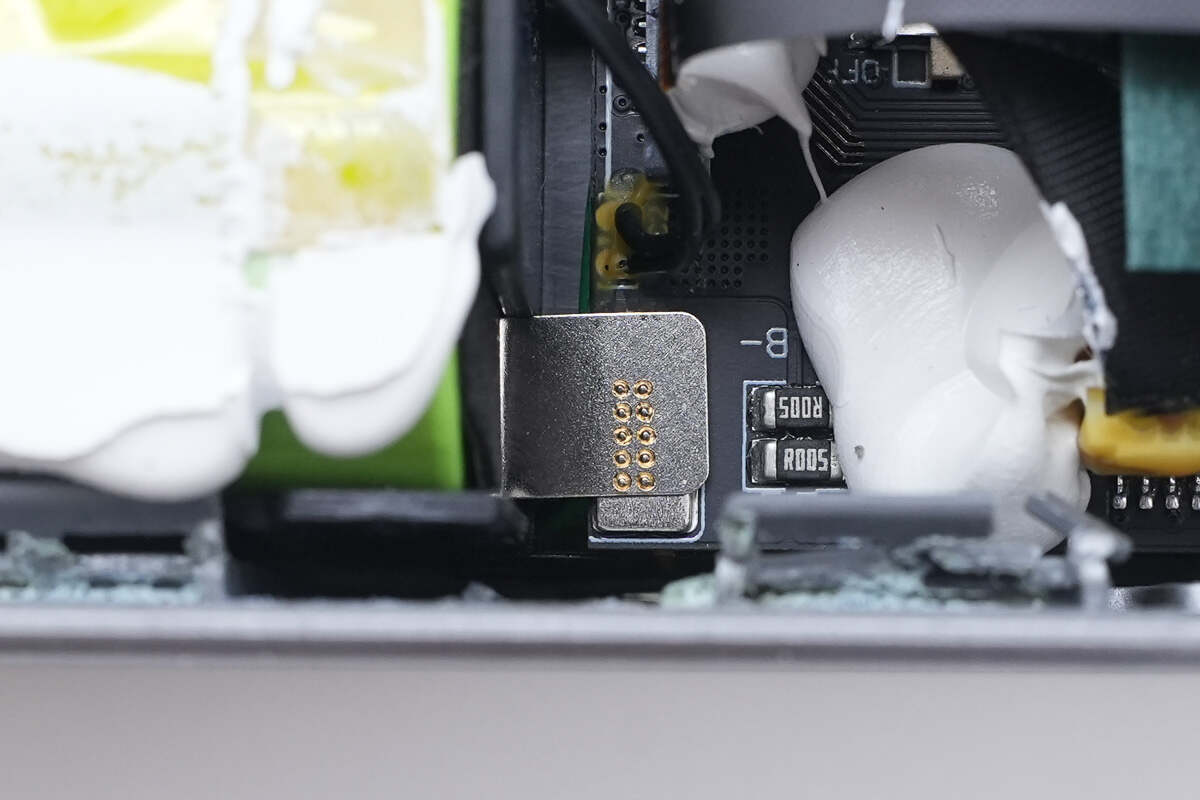
The bottom battery cell connects to the main PCB via plug-in wires, with the connector socket reinforced using adhesive.

The display is housed in a plastic casing for support and protection, secured by screws on both sides above the retractable cable module.
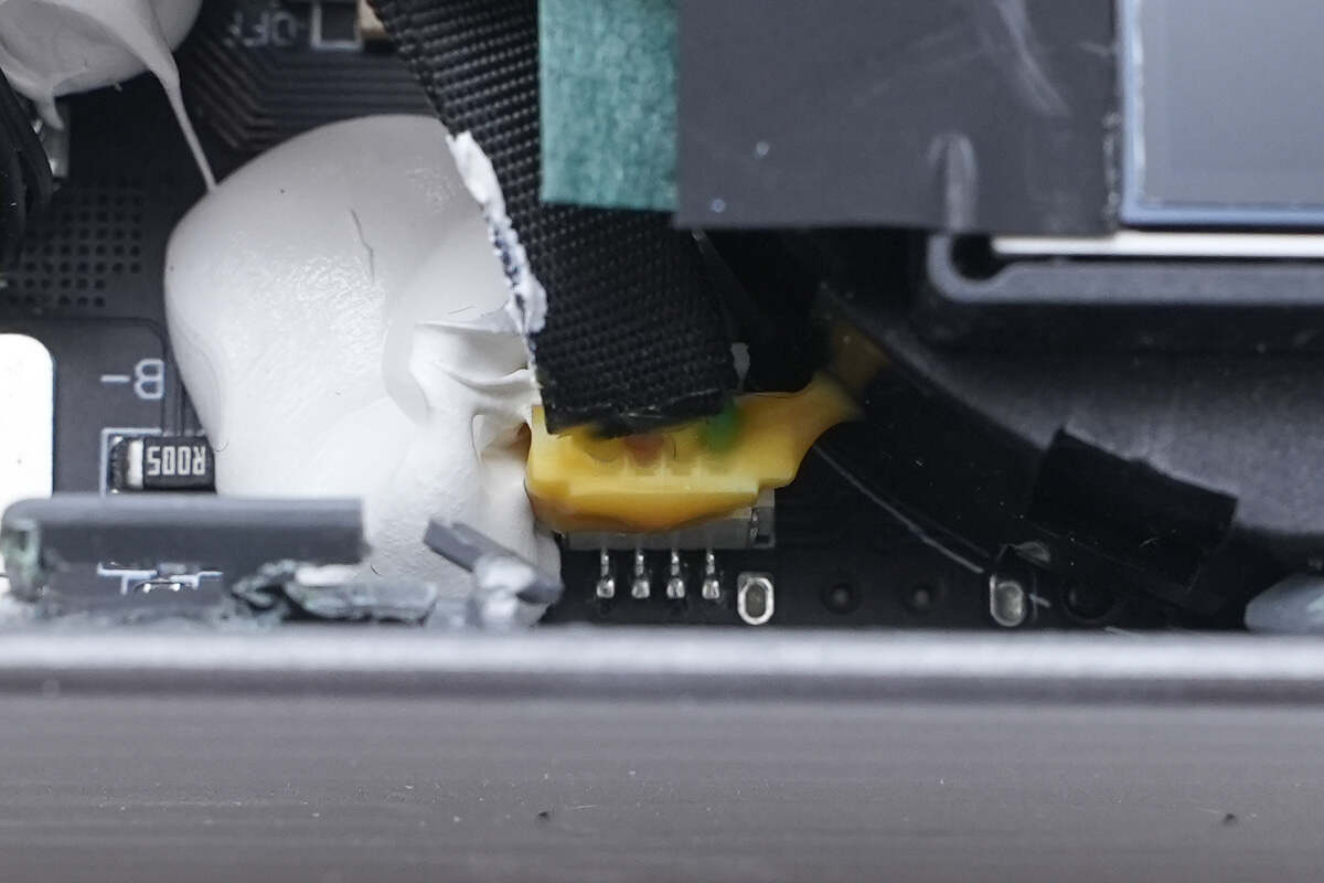
The display connects to the main PCB via a detachable flex cable, with the connector reinforced using adhesive for added durability.

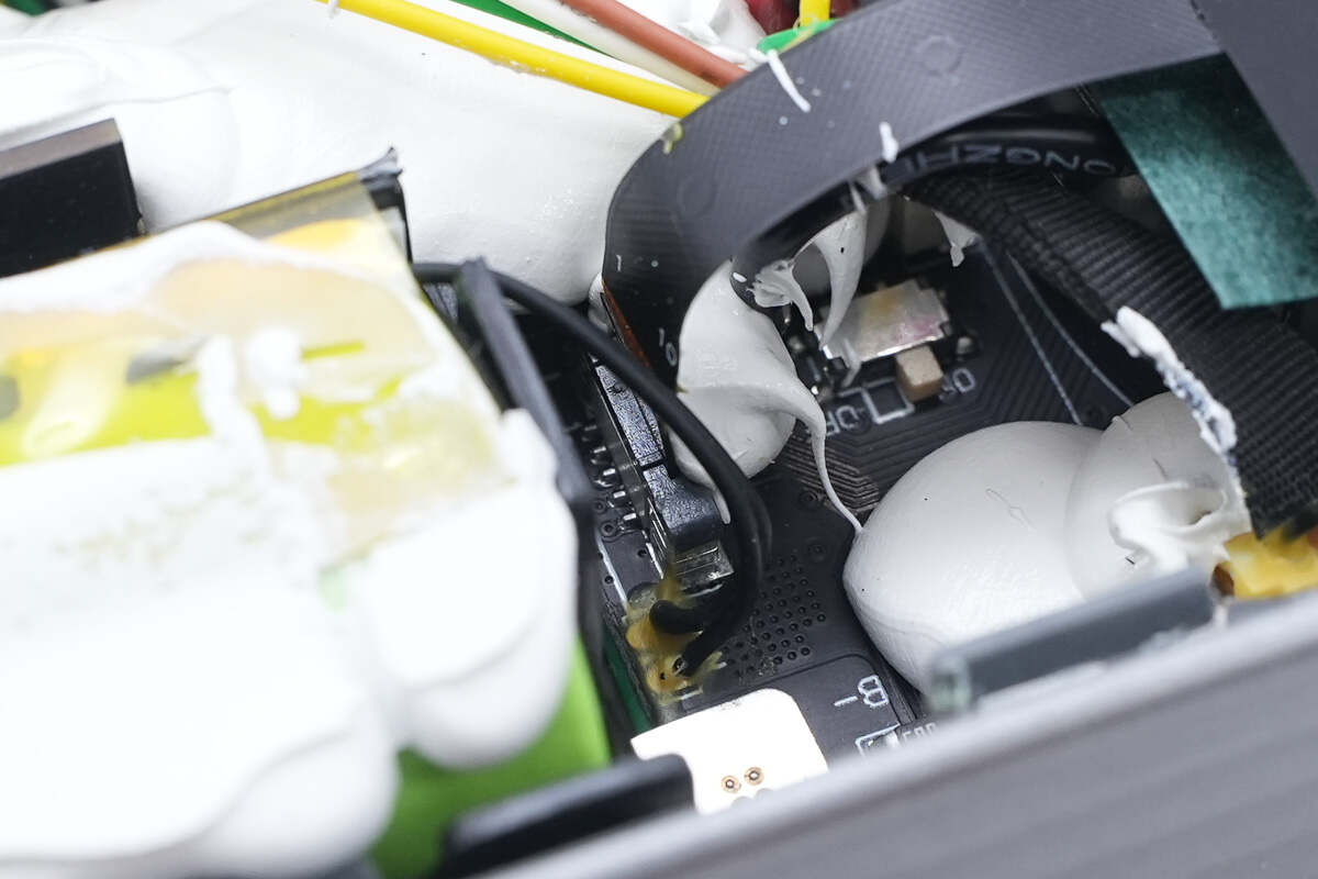
The retractable cable module is also secured with screws. The USB-C2 lanyard cable wires are soldered to the back of a small green PCB, with the wiring protected by adhesive.
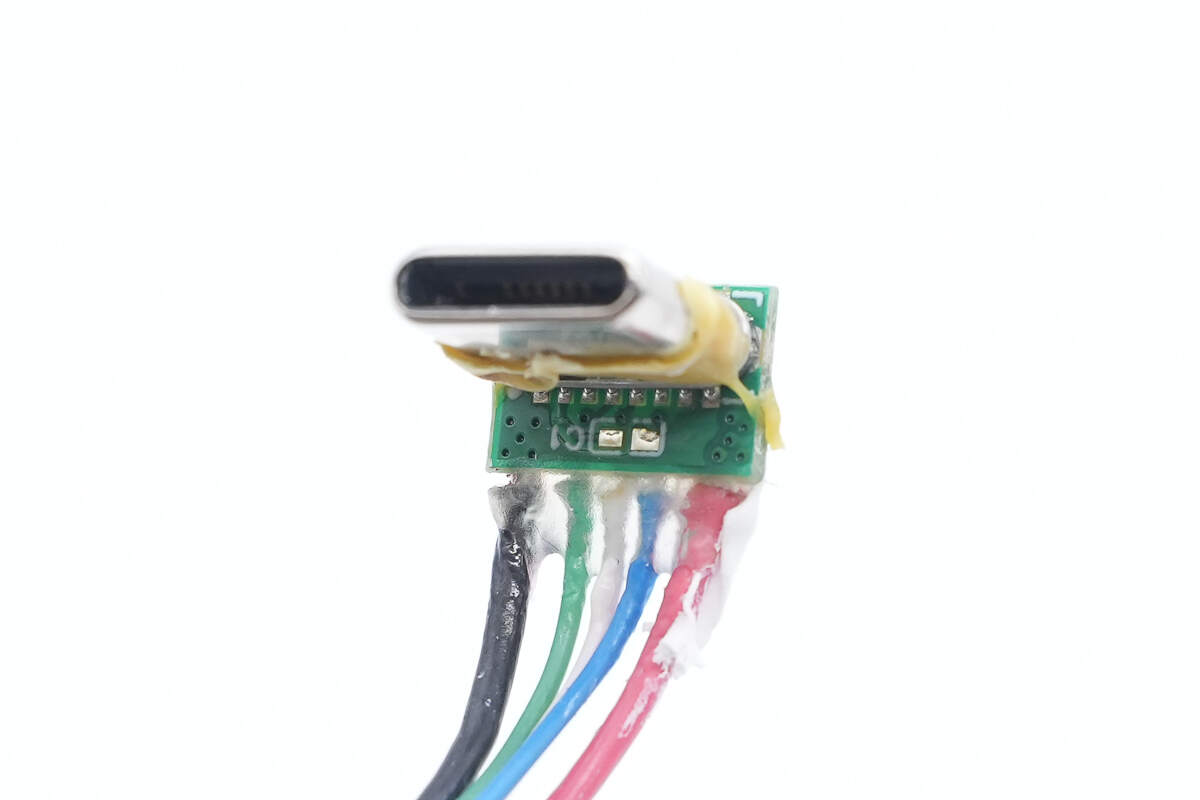
The other side of the small PCB is soldered to a USB-C male connector. The USB-C2 lanyard cable connects to the main PCB's USB-C female port through this module via a plug-in connection, which is also reinforced with adhesive.
Remove the screws to take out the display.
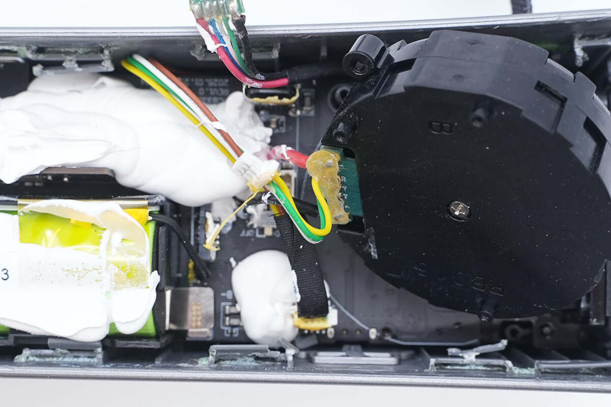
The retractable cable module connects to the main PCB via plug-in connections using thin yellow, white, and green wires, while the thicker red and black wires are soldered directly.
Disconnect the wire connectors from each group and remove the module.
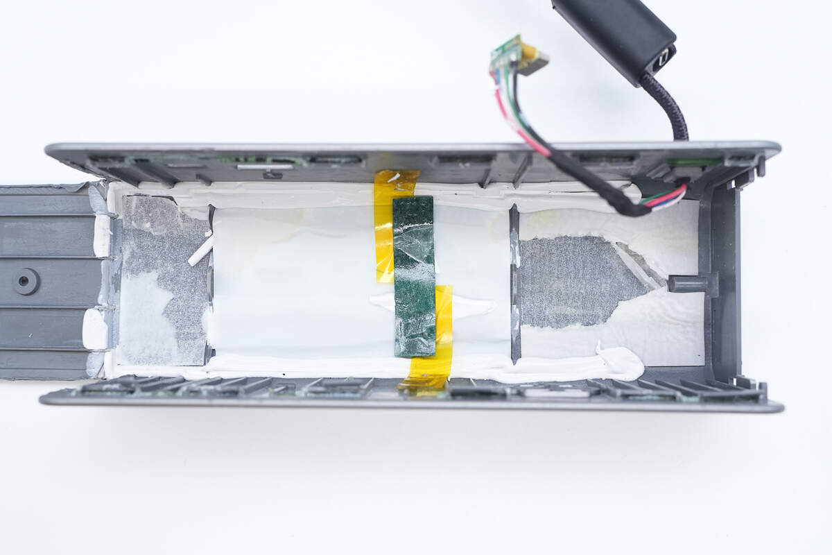
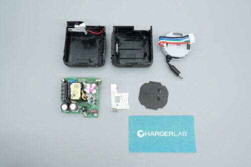
The other half of the casing is also lined with foam, with white adhesive applied on both sides to help secure it in place.
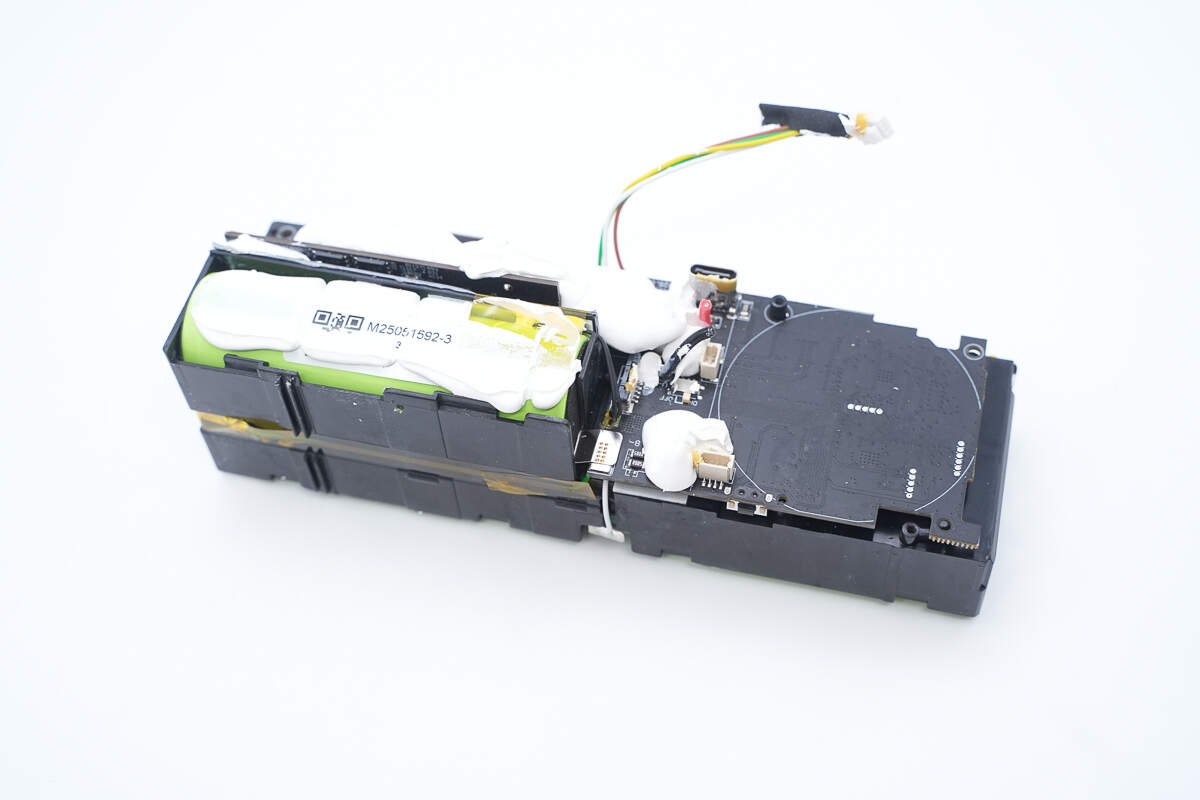
The module uses an integrated plastic frame to isolate and secure the PCB and battery cell. The PCB is fixed by a mounting post at the top, while the single battery cell is placed within a dedicated compartment.
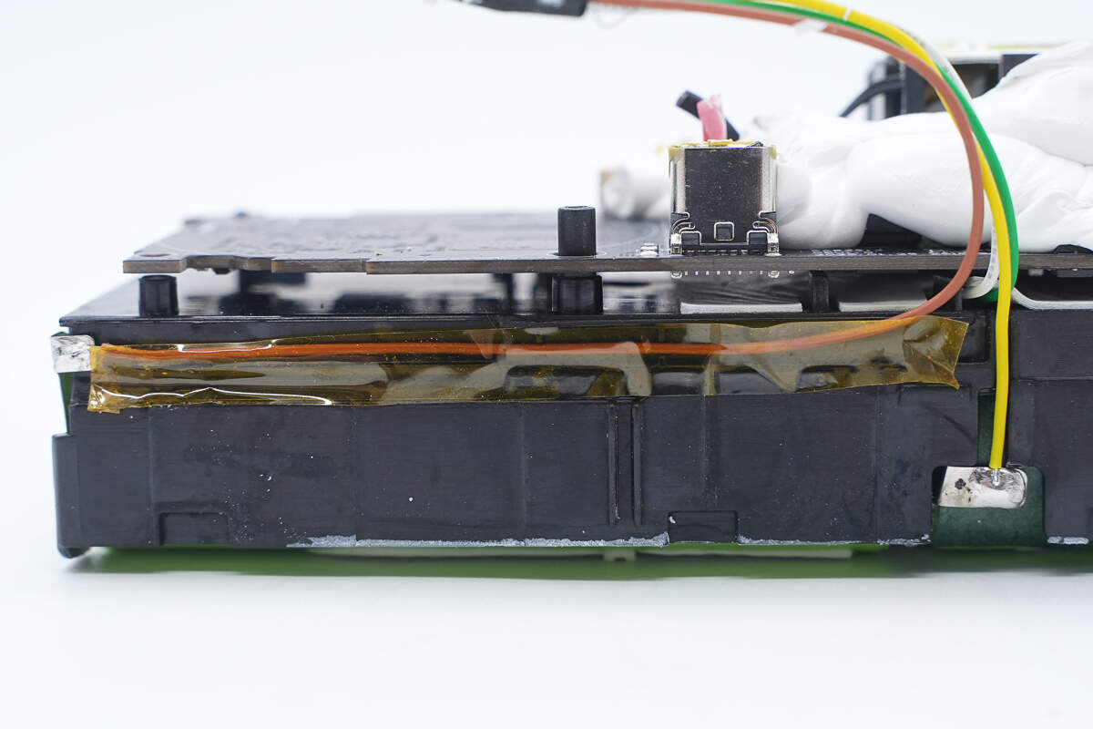
The main PCB is supported by mounting posts that create the gap, effectively preventing heat buildup.
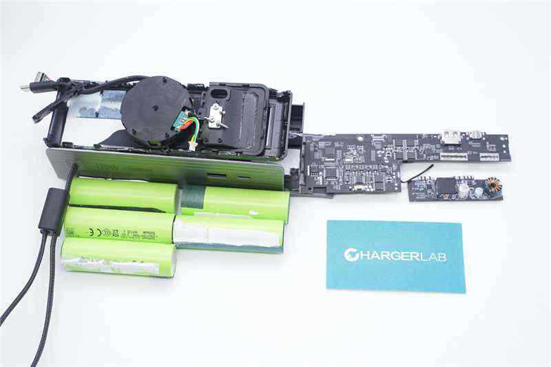
At the bottom, there are four battery cells protected with insulating paper and reinforced with adhesive.
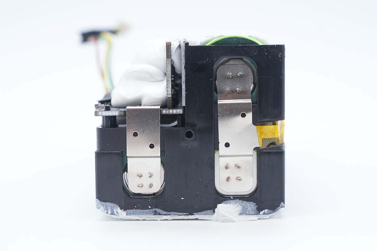
The battery cells are connected by spot-welded nickel strips.
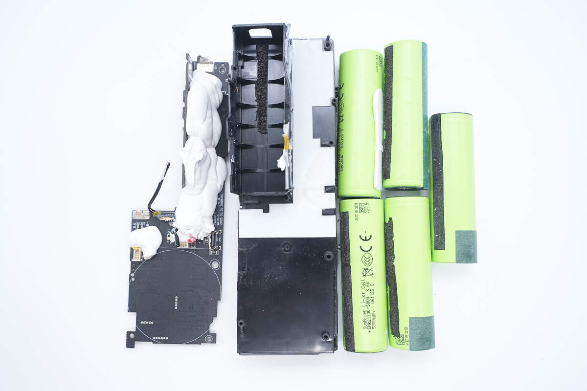
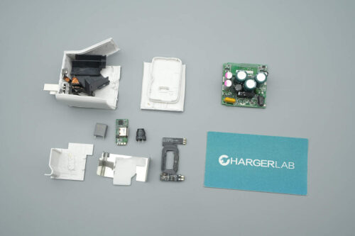
Separate the PCBA module from the battery pack. Protective foam is attached inside the L-shaped area at the top of the plastic frame.
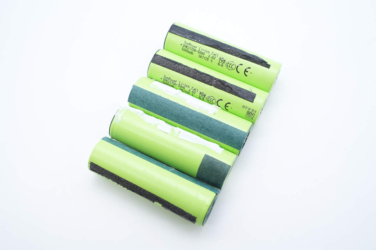
The battery pack consists of five identical 21700 lithium-ion cells.
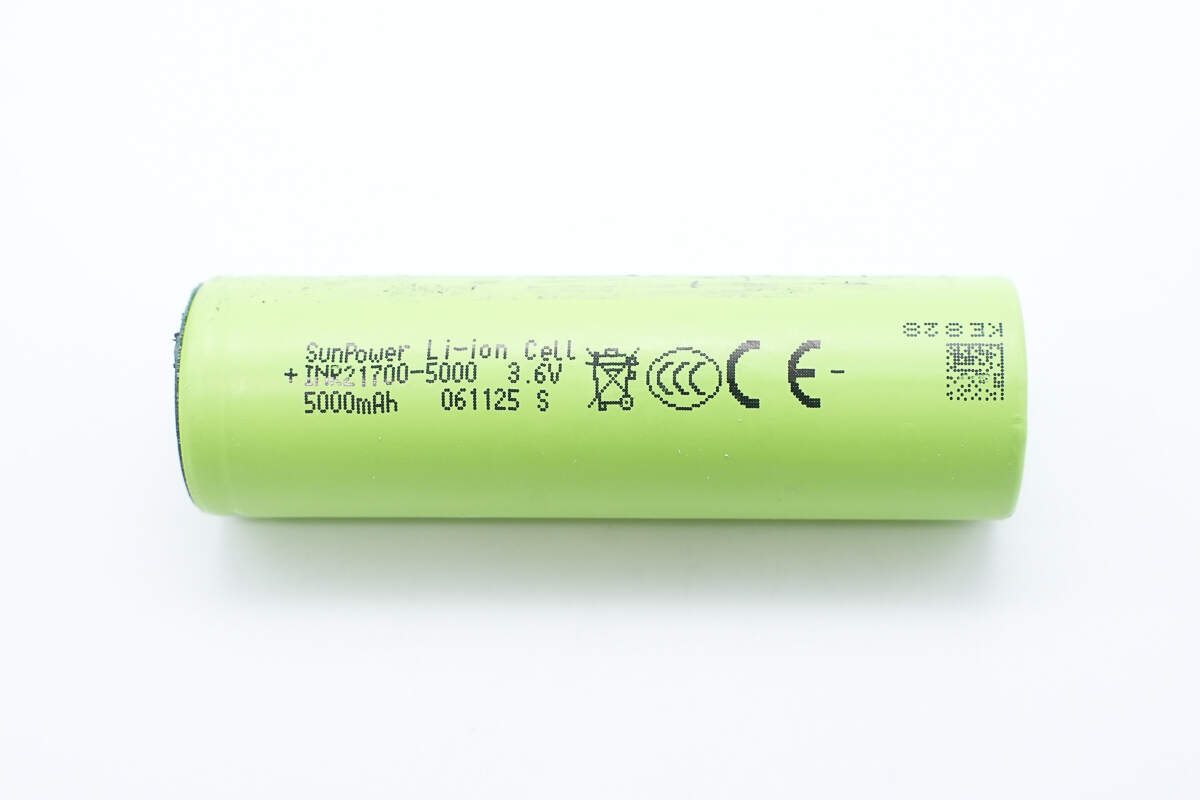
The five battery cells are from SunPower, model INR21700-5000, with a nominal voltage of 3.6V and a rated capacity of 5000mAh. They have a charging cutoff voltage of 4.2V and have passed CCC and CE certifications.

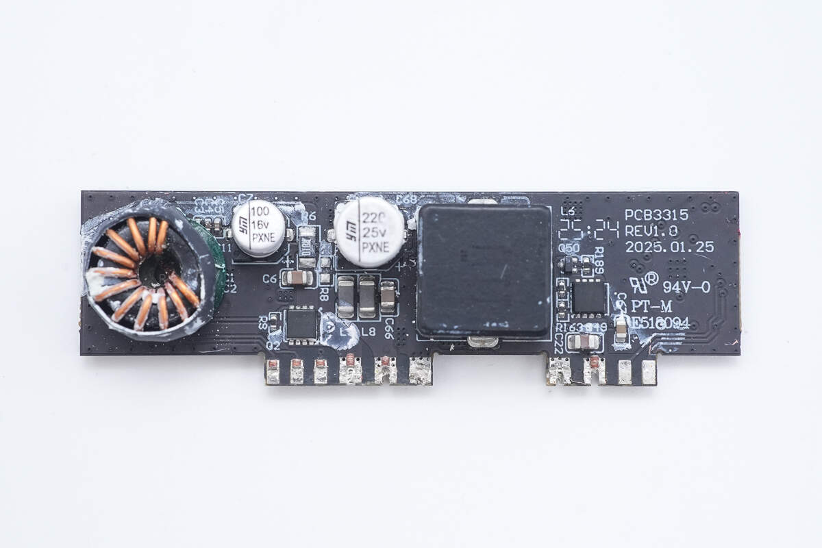
Clean off the white adhesive on the PCBA module. On the main PCB, there is a small vertical PCB attached.
Separate the small PCB from the main PCB.
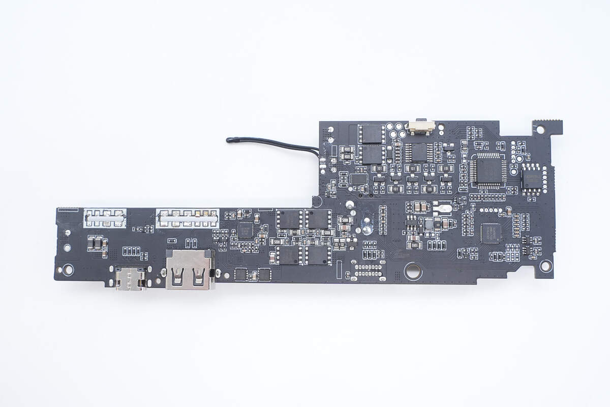
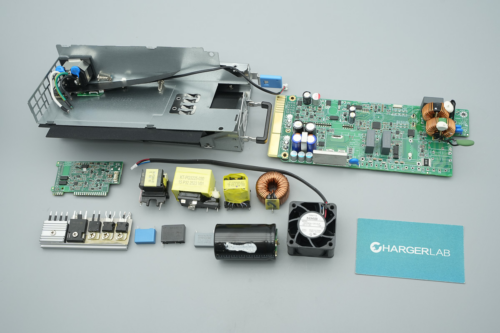
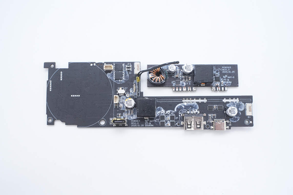
The front side of the main PCB is equipped with a battery protection chip, battery protection MOSFETs, a battery fuel gauge chip, an MCU, a memory, a PD controller, switching switches, synchronous buck-boost controllers, synchronous buck-boost MOSFETs, VBUS MOSFETs, and a synchronous buck converter, among other components.
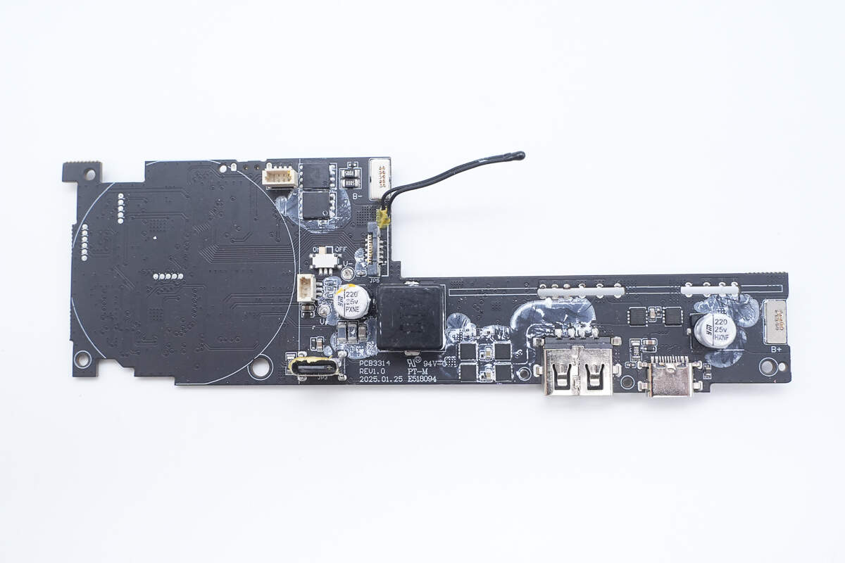
The back side features two battery protection MOSFETs, a buck-boost inductor, solid capacitors, and VBUS MOSFETs.

One side of the small PCB houses an additional synchronous buck-boost controller, synchronous buck-boost MOSFETs for a separate power regulation circuit, and a step-down protocol chip dedicated to the USB-A port.
The other side features an inductor for two voltage regulation circuits, solid capacitors, and VBUS MOSFETs.

The battery protection chip used is the iCM CM1351-BAT, a dedicated protection IC for 5-series lithium-ion or LiFePO₄ battery packs. It integrates high-precision voltage and current detection circuits. By monitoring the voltage of each cell, charge/discharge current, and temperature, it provides protection features such as overcharge, overdischarge, cell balancing, open-wire detection, low-voltage charge inhibition, discharge overcurrent, short-circuit, charge overcurrent, and over-temperature protection. The discharge overcurrent protection delay is adjustable via an external capacitor, while other protection delays are internally set. The chip also features built-in cell balancing functionality.

The iCM CM1351 offers a battery overcharge protection accuracy of 15mV. It supports three-level discharge overcurrent protection, charge overcurrent protection, individual cell open-wire protection, and NTC thermistor disconnection protection. This enables comprehensive protection for multi-cell lithium battery packs.
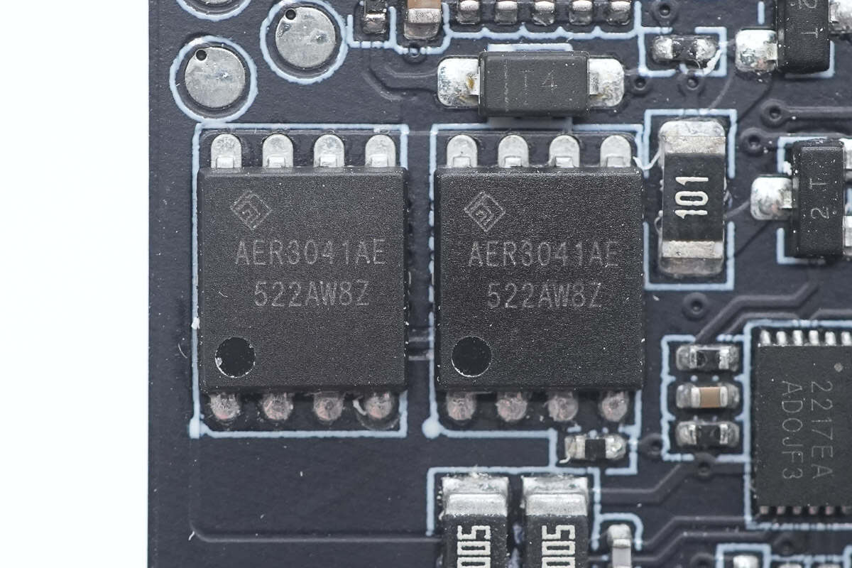
The four battery protection MOSFETs are from ALLEPIC, model AER3041AE. These are N-channel MOSFETs with a voltage rating of 30V and an on-resistance of 3.2mΩ. They come in a PDFN5060 package.
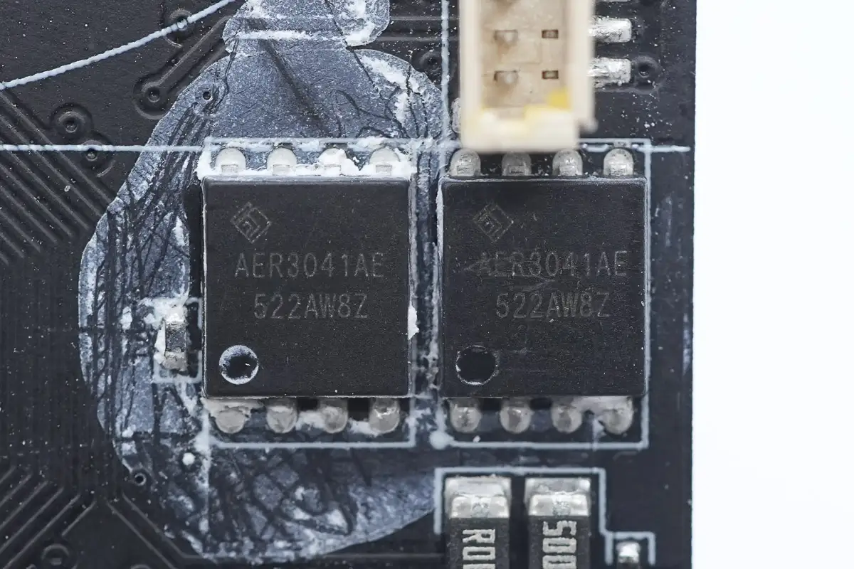
The other two AER3041AE MOSFETs are located on the reverse side of the main PCB.
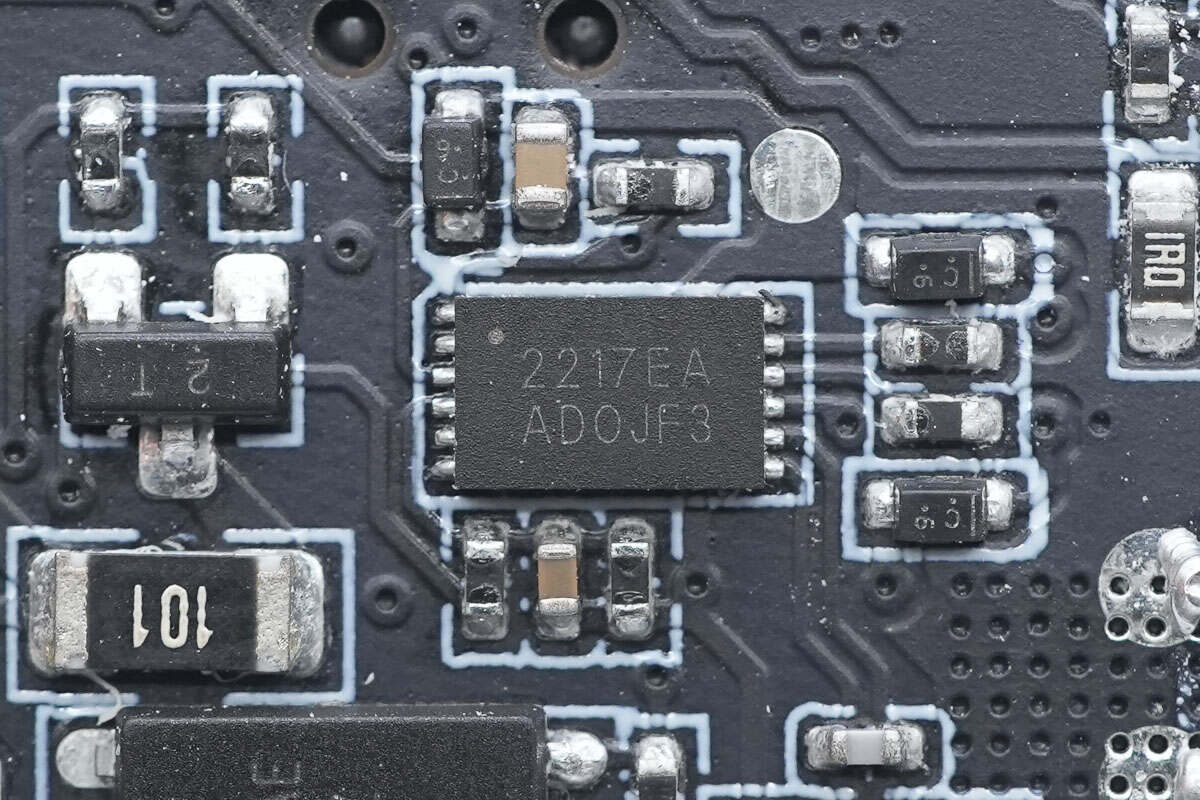
The battery fuel gauge chip is from Cellwise, model CW2217EAAD. It is an ultra-compact solution designed for lithium-ion batteries in wearable and portable devices, suitable for integration either on the system side or within the battery pack.
This chip tracks battery operating status and uses advanced algorithms to accurately calculate the state of charge (SOC) for various lithium chemistries, including lithium cobalt oxide (LiCoOx), lithium polymer, and lithium manganese oxide (LiMnOx). It comes in a lead-free DFN-12 package.

The synchronous buck-boost controller is from SouthChip, model SC1815A, and it comes in a QFN32 package.
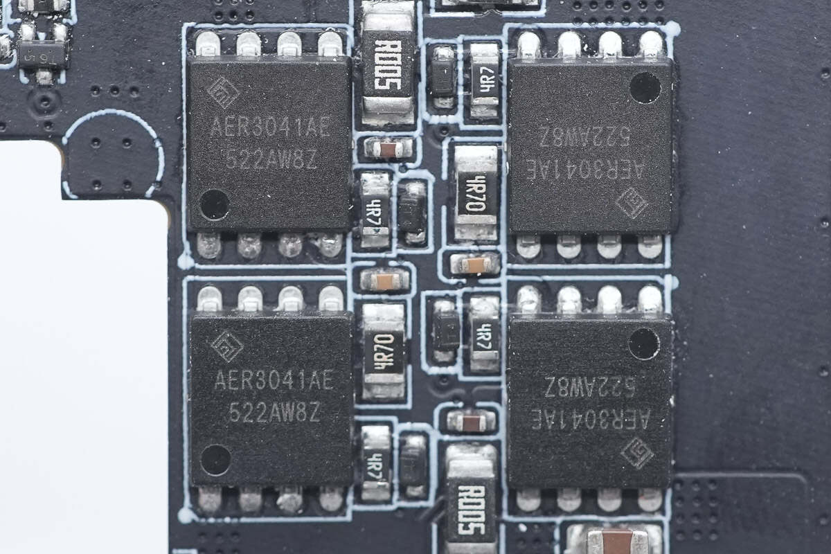
The four synchronous buck-boost MOSFETs paired with it are also ALLEPIC AER3041AE models.
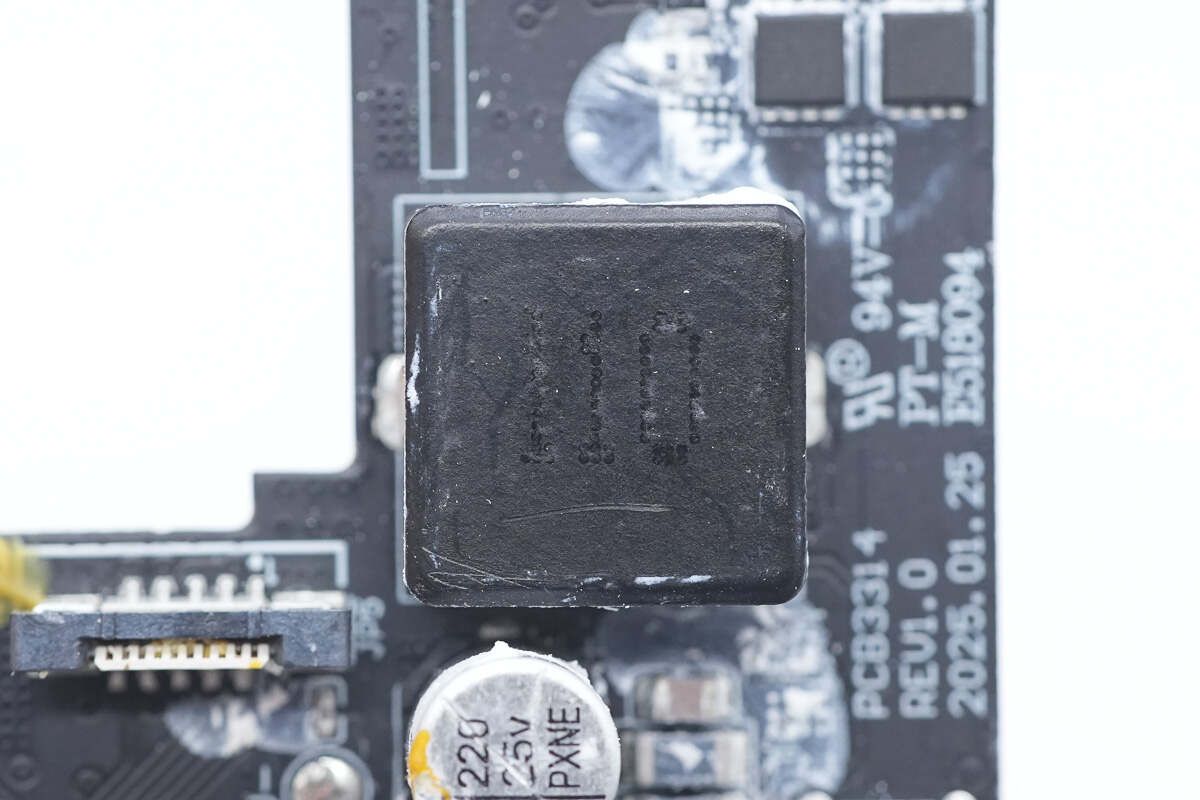
Close-up of the 11μH buck-boost inductor.
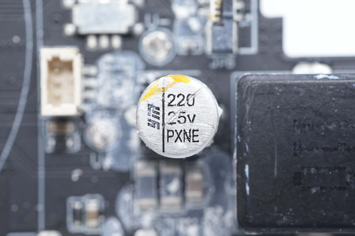
The solid capacitor is from YMIN, rated at 25V and 220μF.
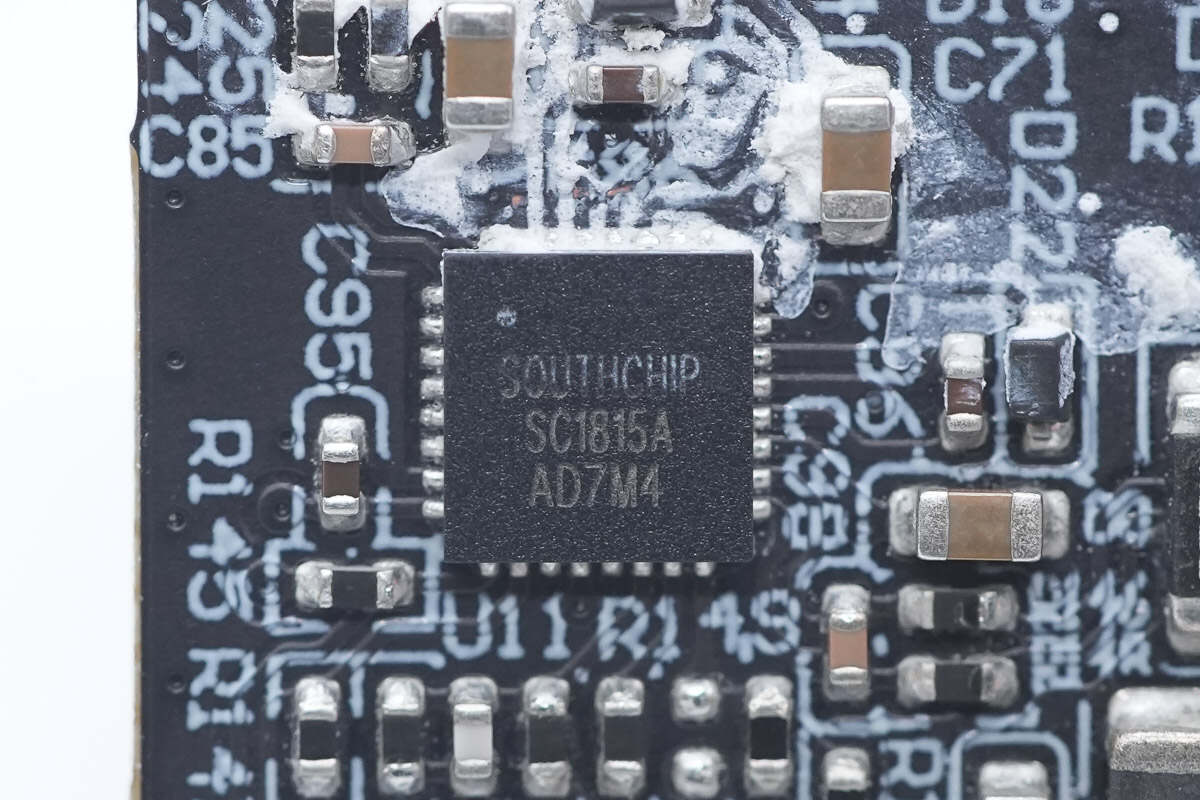
The synchronous buck-boost controller is also a SouthChip SC1815A.
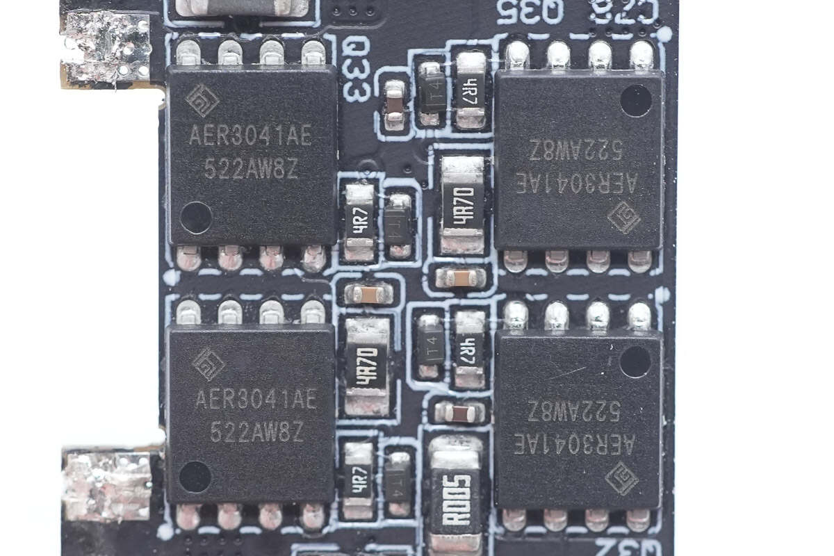
The four synchronous buck-boost MOSFETs are also ALLEPIC AER3041AE models.
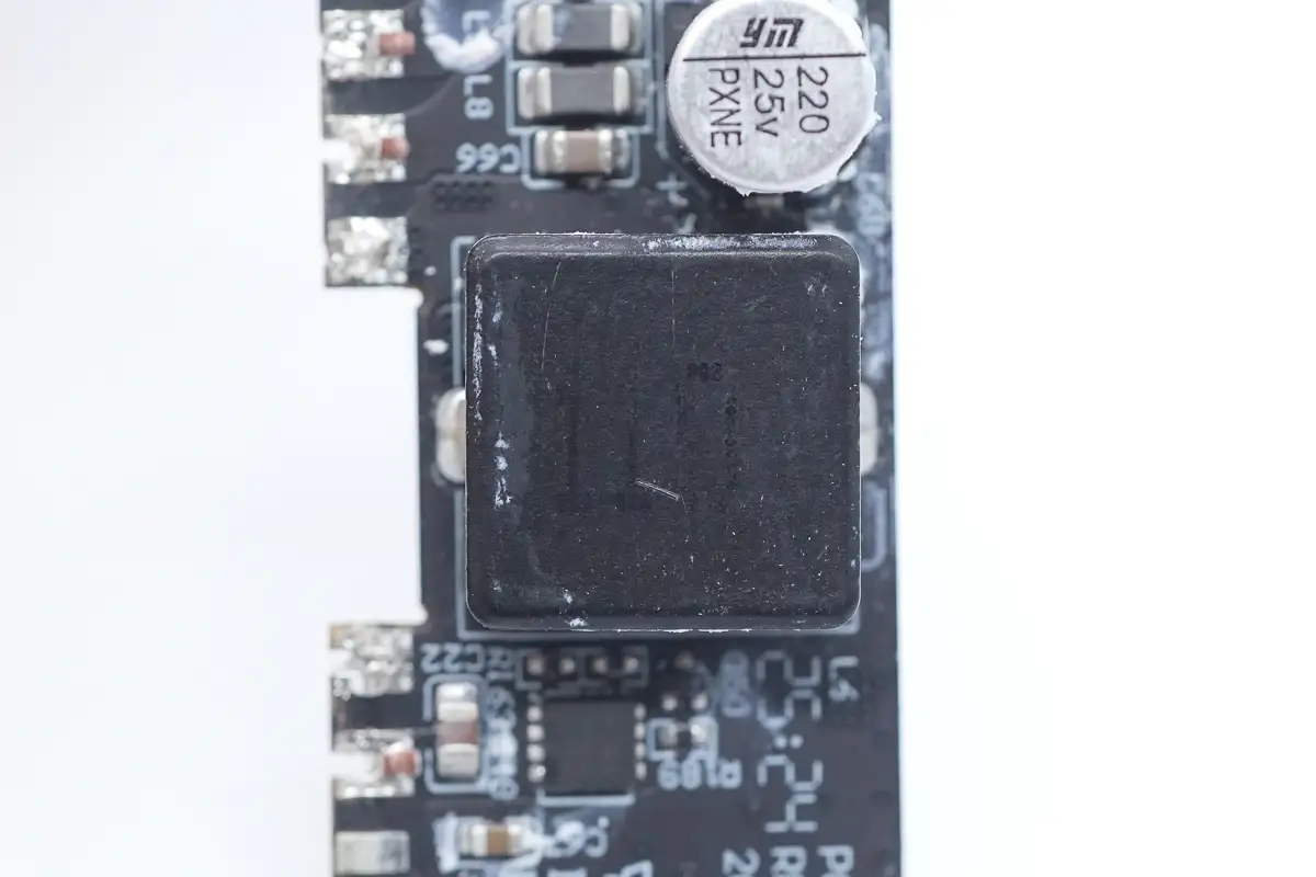
Close-up of the 11μH buck-boost inductor.
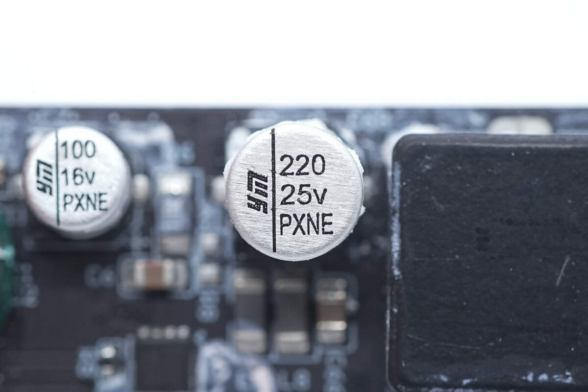
The solid capacitor is from YMIN, and the specification is also 25V 220μF.
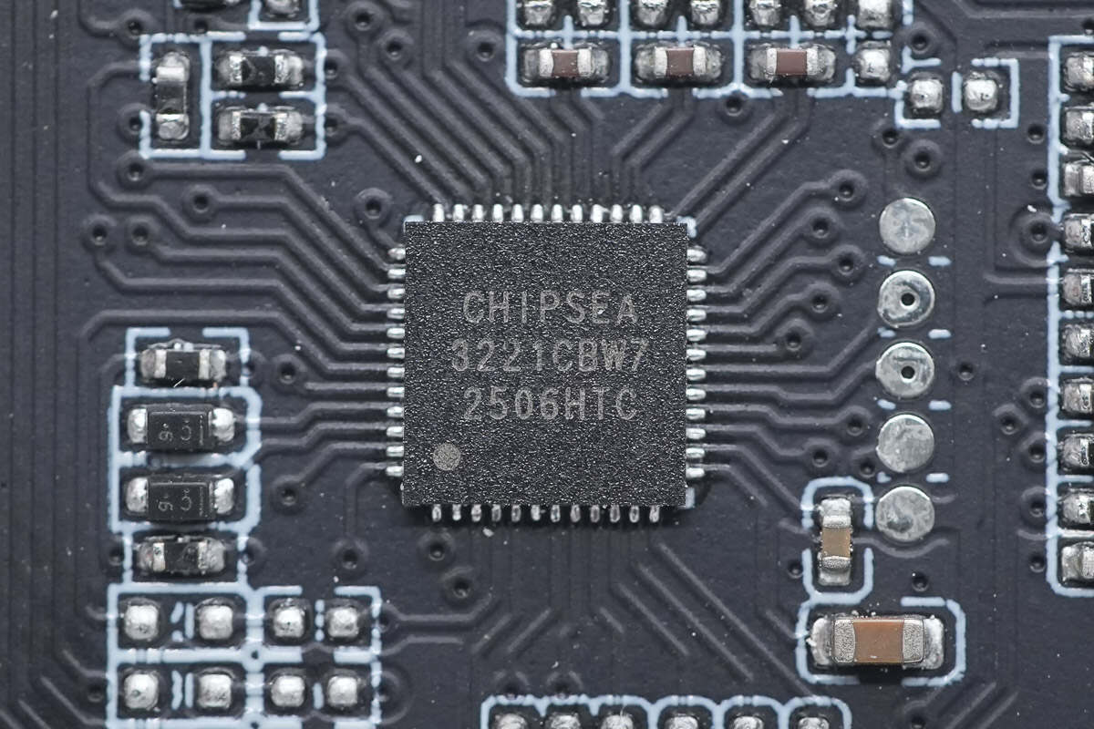
The bidirectional fast-charging controller for the two built-in cables and the USB-C3 port uses the Chipsea CPW3221. This USB Type-C and USB PD controller is designed for power banks, BMS, wireless charging, and display applications. It integrates all Type-C CC and USB PD functions, as well as USB BC1.2 support. Additionally, it includes multiple fast-charging protocols to enhance compatibility with various mobile devices.
The CPW3221 features a 32-bit microprocessor running at 48MHz, suitable for a wide range of industrial control and high-performance CPU applications. It includes 128KB of program Flash memory, 24KB of SRAM, and various peripherals such as I/O ports, timers, USART, I2C, ADC, watchdog timers, making it versatile for broader uses. The chip is available in QFN32 and QFN48 packages.
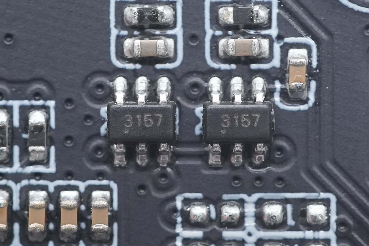
There are two switches marked with "3157."
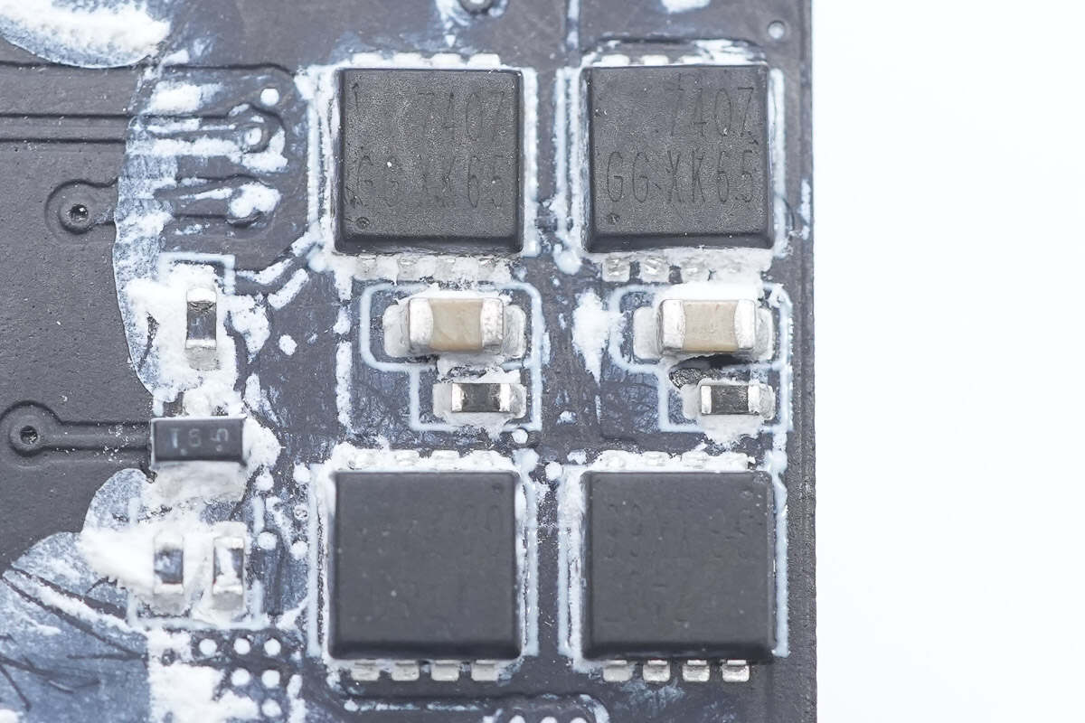
The four VBUS MOSFETs are marked with "7407."
The VBUS MOSFETs used for the USB-C3 port are marked with "7407."

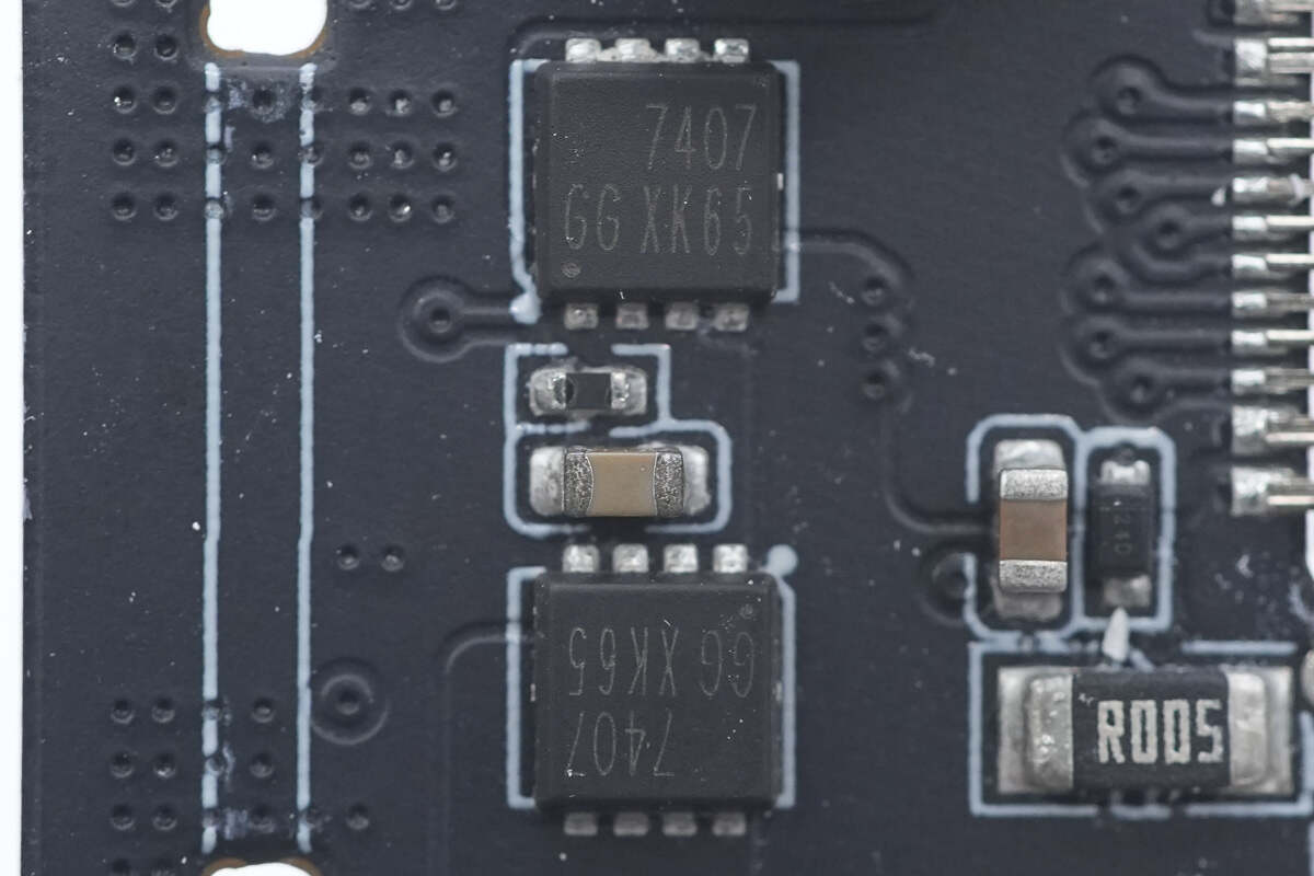
Another set of VBUS MOSFETs marked "7407" is located on the front side of the main PCB.

There is also a VBUS MOSFET marked "7407" on the small PCB.

This solid capacitor is from YMIN, rated at 25V and 220μF.
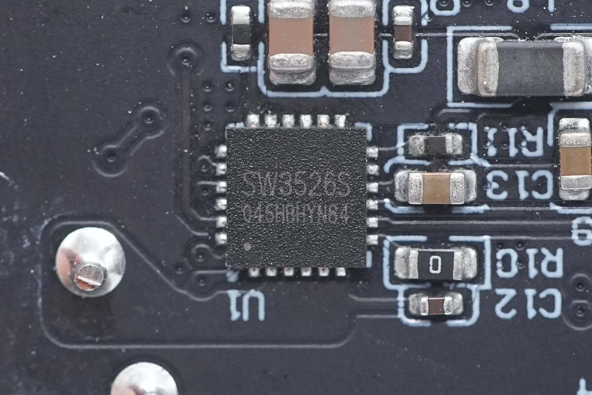
The buck protocol chip for the USB-A port is from iSmartWare, model SW3526S. It integrates a 3.5A high-efficiency synchronous rectification buck converter and supports multiple charging protocols, including PPS, PD, QC, AFC, FCP, SCP, PE, SFCP, and low-voltage direct charging. It operates in CC/CV mode and requires only a few external components to form a complete high-performance multi-protocol fast-charging solution.
Thanks to its high integration, the SW3526S consolidates the protocol chip, synchronous buck controller, and buck MOSFETs—traditionally separate components in fast-charging designs—into a single package, greatly simplifying the circuit design for multi-port fast charging.

Here is the information about iSmartWare SW3526S.
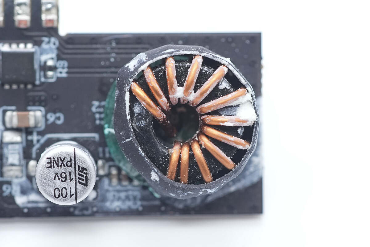
The buck-boost inductor is insulated with a heat-shrink tube on the outside, and the bottom is lined with insulating paper.
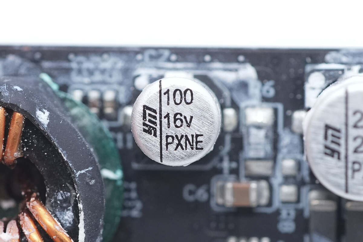
The solid capacitor is from YMIN, rated at 16V and 100μF.
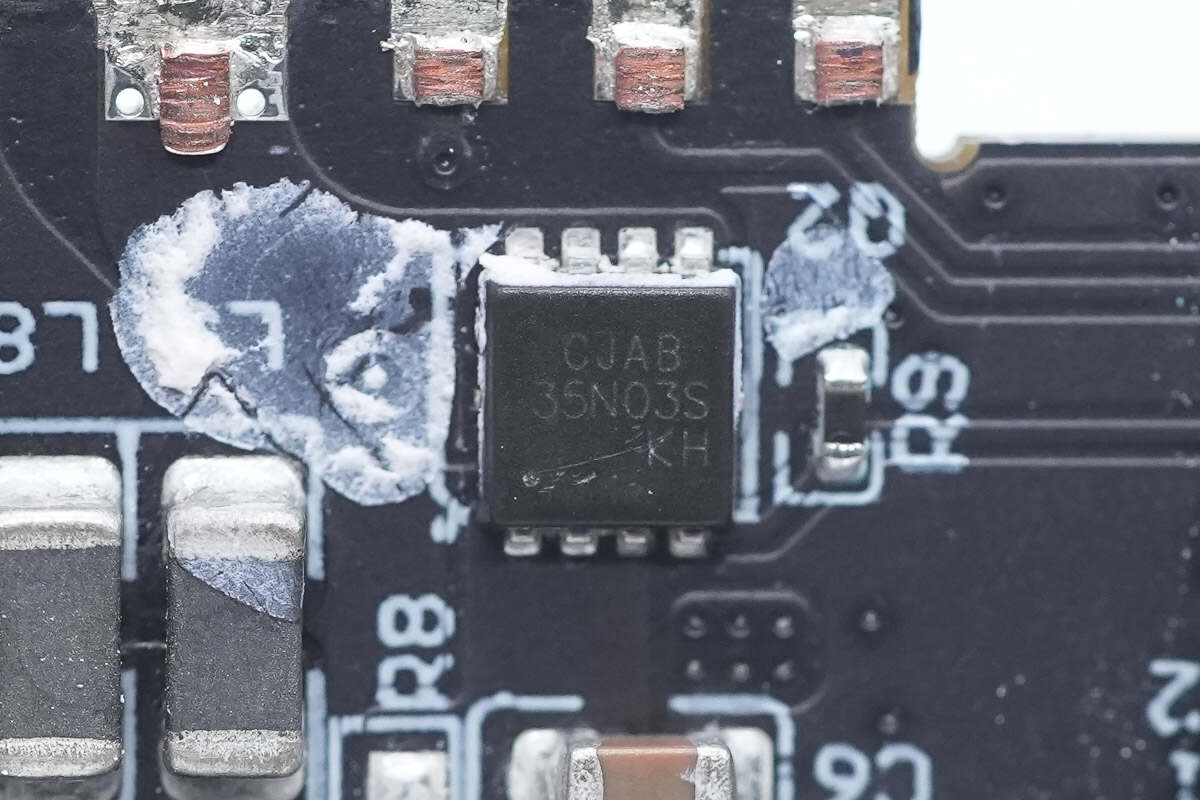
The USB-A port VBUS MOSFET is from JSCJ, model CJAB35N03S. It is an N-channel MOSFET with a voltage rating of 30V and an on-resistance of 5.2mΩ, packaged in a PDFNWB 3.3×3.3-8L package.
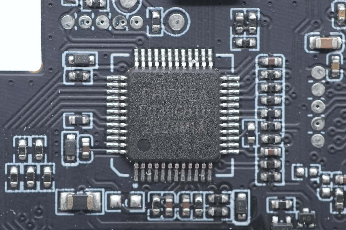
The MCU is from Chipsea, model CS32F030C8T6. It features a 48MHz ARM Cortex-M0 CPU, with 64KB of FLASH memory and 8KB of SRAM. It includes two UART interfaces, two SPI interfaces, and two I2C interfaces, all housed in an LQFP48 package.
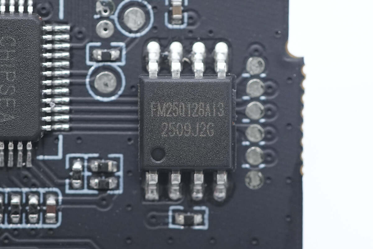
The memory chip is from FUDAN, model FM25Q128AI3. It is a 16MB serial flash memory with a wide operating voltage range. It supports standard Serial Peripheral Interface (SPI), dual/quad I/O, and quad peripheral interface (QPI) with dual-clock instruction cycles. The chip comes in an SOP8 package.

The synchronous buck converter powering the MCU and display is from TI, marked "1N72," model LMR14010A. It is a PWM DC/DC step-down regulator featuring a wide input voltage range of 4–40V and an ultra-low shutdown current of 1µA to extend battery life. Operating at a fixed frequency of 0.7MHz, it allows the use of small external components while minimizing output ripple voltage. The device comes in a slim TSOT-6L package and is suitable for various industrial and automotive applications.

Close-up of the step-down inductor.
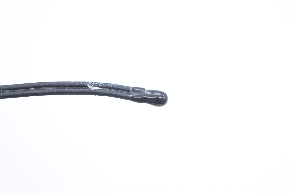
Close-up of the thermistor.

Close-up of the display.
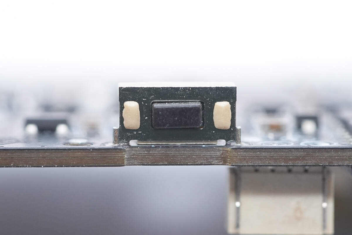
Close-up of the power button.
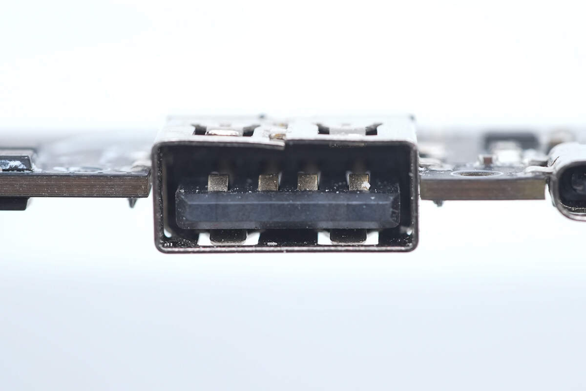
The USB-A socket is mounted using plated through-hole soldering.
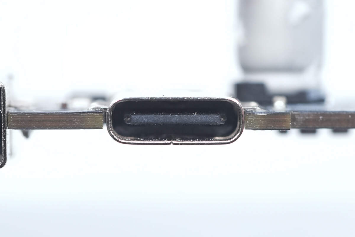
The USB-C3 socket is also mounted using plated through-hole soldering.
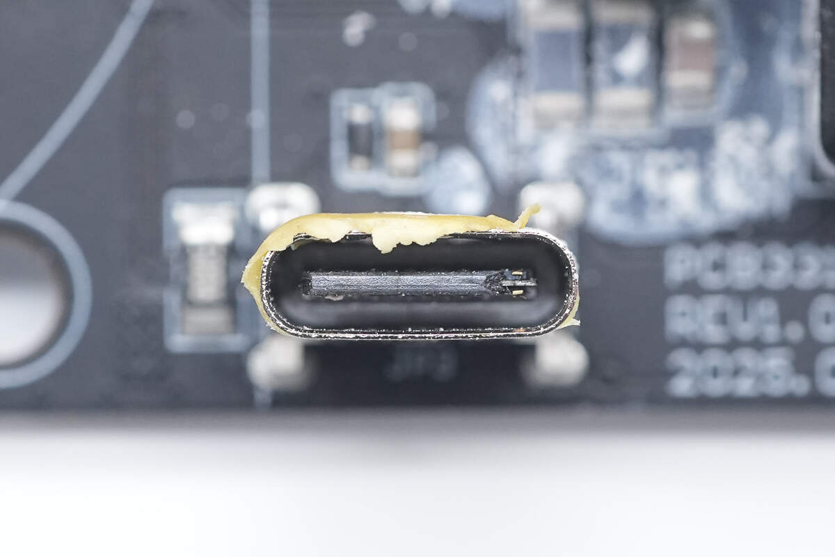
A close-up view of the female connector used to connect the USB-C2 lanyard cable’s male plug.

Disassemble the retractable cable module.

Inside the top housing, there is a magnet designed to hold the USB-C1 retractable cable connector securely in place.
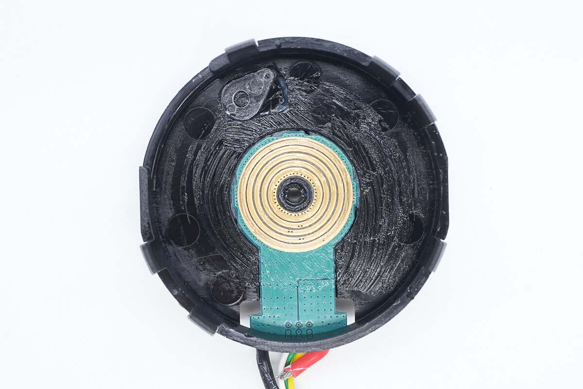
Close-up of the slip ring.
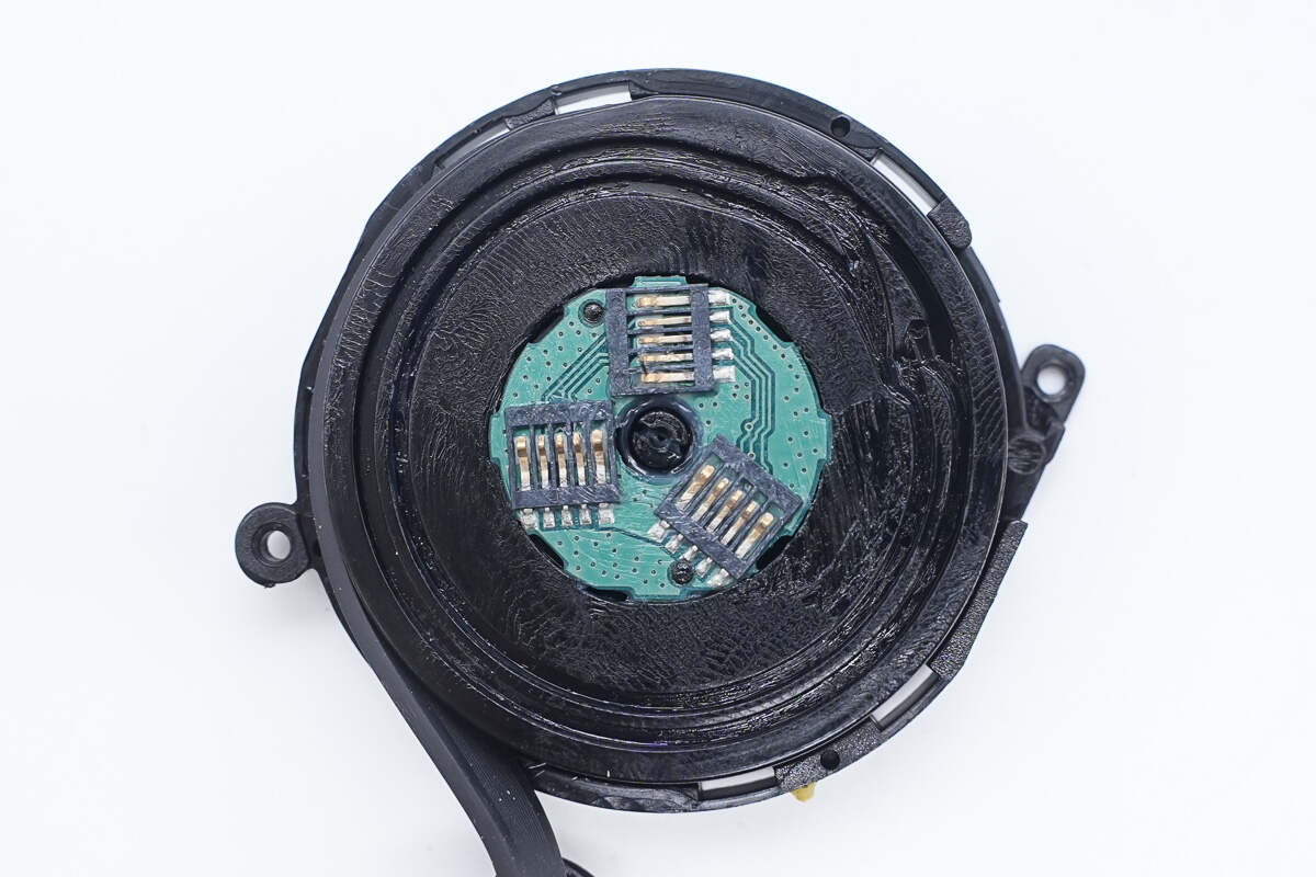
The spool is equipped with three brushes to enhance current-carrying capacity.
Well, those are all components of the EcoFlow RAPID 170W 25,000mAh Power Bank with Built-in Cable.
Summary of ChargerLAB

Here is the component list of the EcoFlow RAPID 170W 25,000mAh Power Bank with Built-in Cable for your convenience.
It comes equipped with a USB-C retractable cable, a lanyard cable, one USB-C port, and one USB-A port. The feature-rich TFT color display shows remaining battery capacity, input/output power for each port, battery health, and more. The two built-in cables measure 65 cm and 30 cm in length, respectively. Both cables and the USB-C3 port support 100W bidirectional fast charging and are compatible with protocols such as UFCS, PPS, SCP, and QC. With a maximum combined output of 170W, it can fast-charge up to four devices simultaneously.
After taking it apart, we found that the battery pack uses five SunPower INR21700-5000 lithium cells, certified by CCC. It features the iCM CM1351-BAT battery protection solution. The three USB-C ports utilize SouthChip SC1815A buck-boost controllers paired with Chipsea CPW3221 protocol chip to achieve bidirectional fast charging. The USB-A port delivers 18W output through an iSmartWare SW3526S buck SOC. The device also incorporates a Chipsea MCU, FUDAN memory, and a Texas Instruments buck converter for the power supply. The module is securely assembled with screws and reinforced with glue, featuring effective isolation, insulation, structural reinforcement, and cushioning protection, reflecting reliable craftsmanship.
Related Articles:
1. Teardown of Apple iPhone Air MagSafe Battery (A3466)
2. Teardown of Apple 40W Dynamic Power Adapter with 60W Max (A3365)
3. Teardown of CalDigit TS5 Plus Thunderbolt 5 Dock