Introduction
We obtained a Delta SiC server power supply, model DPS-550AB-2. This unit supports both 100–240 V AC input and 240 V DC input. The main output provides 12 V at 45 A, while the standby output delivers 12 V at 3 A, giving a total rated power of 550 W.
On the AC input side, the power module includes a cooling fan, power inlet, status indicator, and release handle. The output side features a gold-finger connector interface. Internally, the design adopts a PFC + LLC + SR topology. Let’s take a closer look at its internal components and design.
Product Appearance

The power supply uses a metal enclosure secured with screws.

The input side is equipped with a cooling fan and grounding spring contacts.
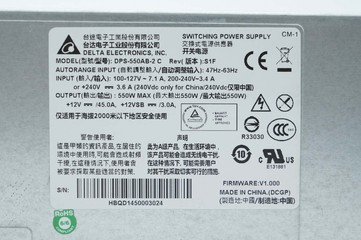
Model: DPS-550AB-2
Input: 100–127V ~ 7.1A,
200–240V ~ 3.4A
+240V ⎓ 3.6A (240V DC for use in China only)
Output: 550W MAX
+12V ⎓ /45A, +12VSB ⎓ /3A
Grounding spring contacts are also provided on the rear side.

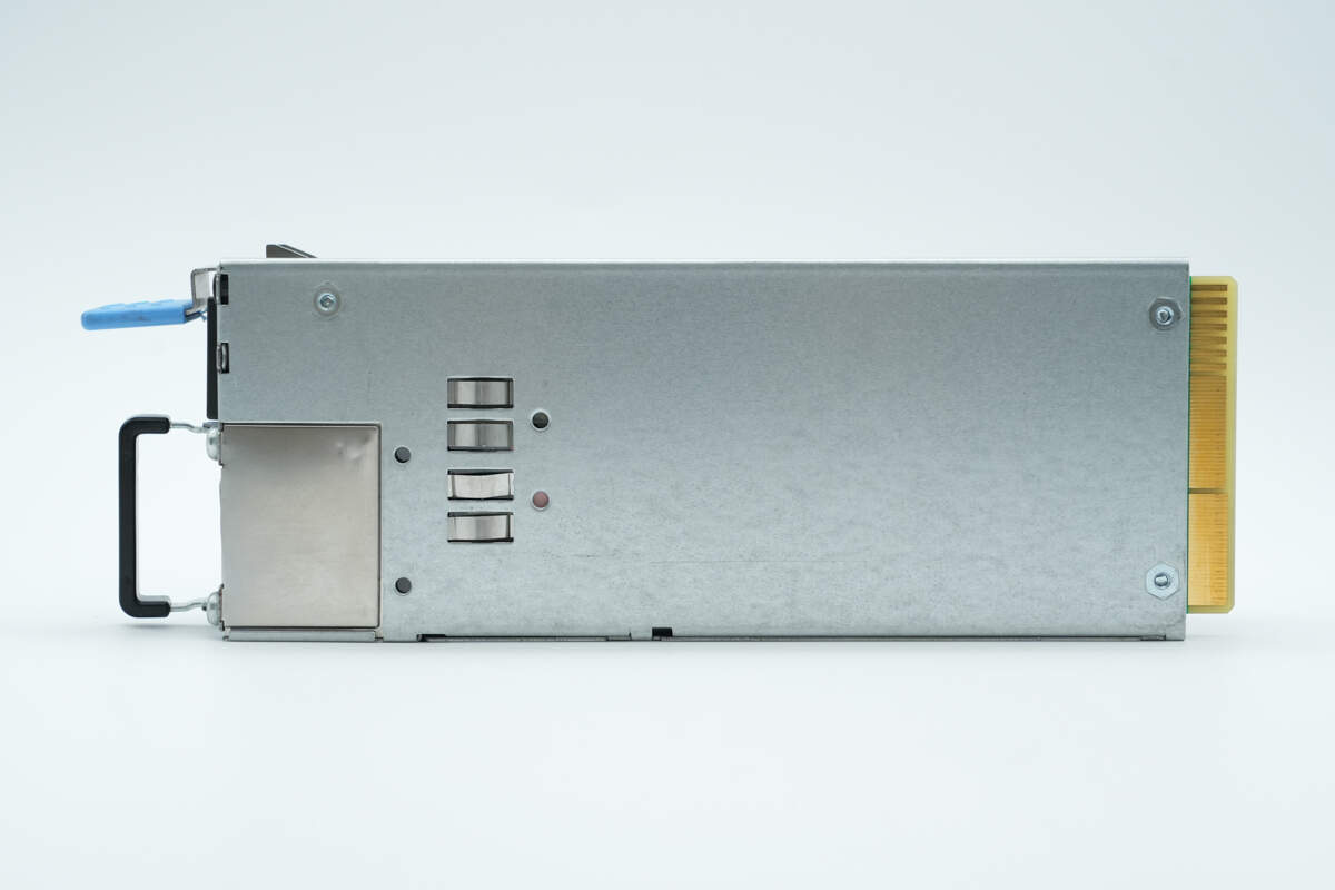
The side of the enclosure is secured with screws.

The input side features a cooling fan, handle, input socket, indicator light, and release latch.
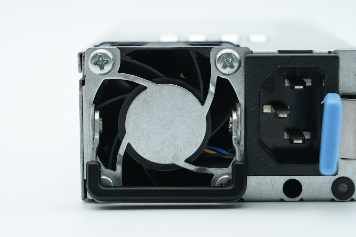
The cooling fan is equipped with a protective grill.

Close-up of the three-prong input socket.
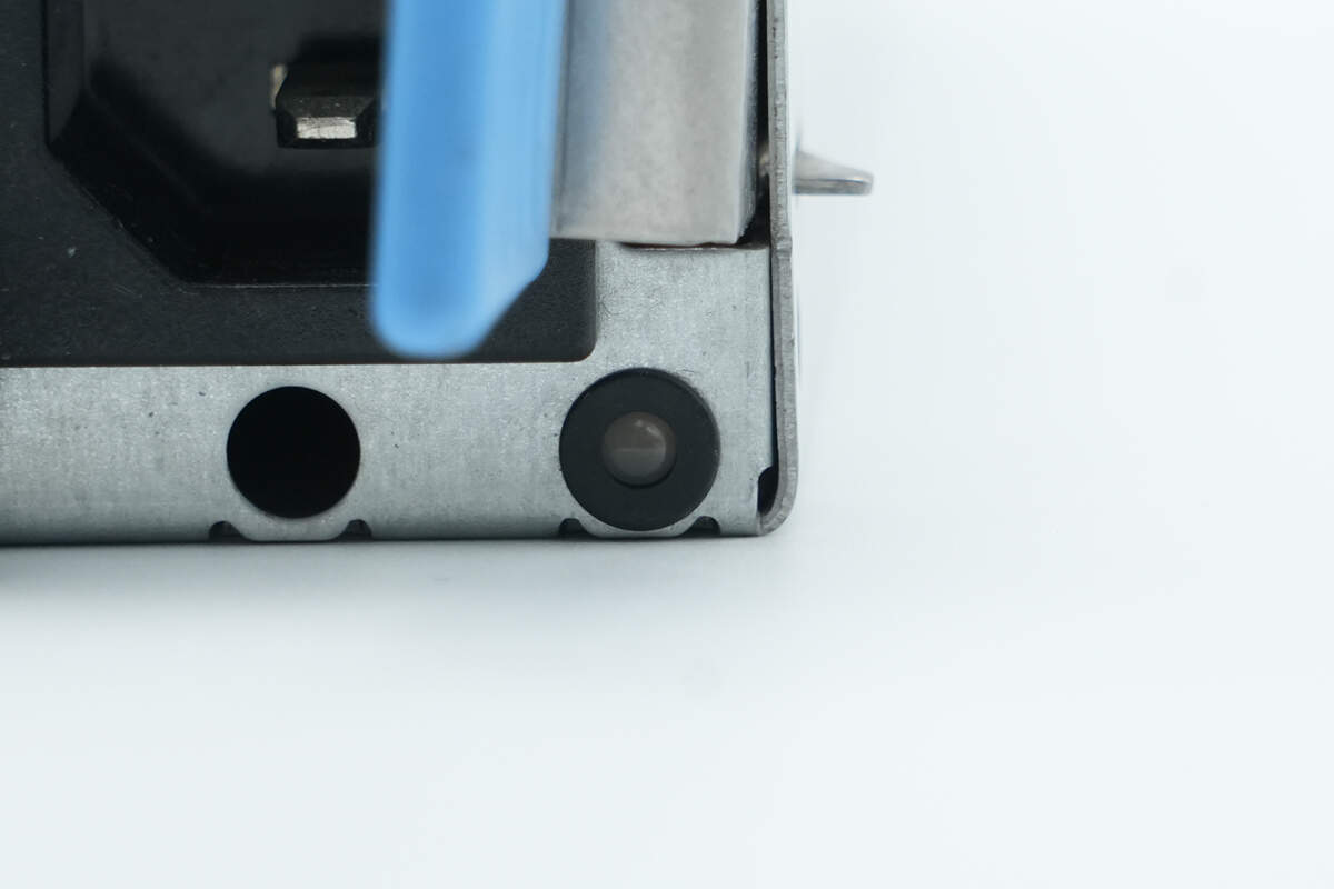
Below is the LED indicator.

The output side features a gold-finger connector and a ventilation grille.
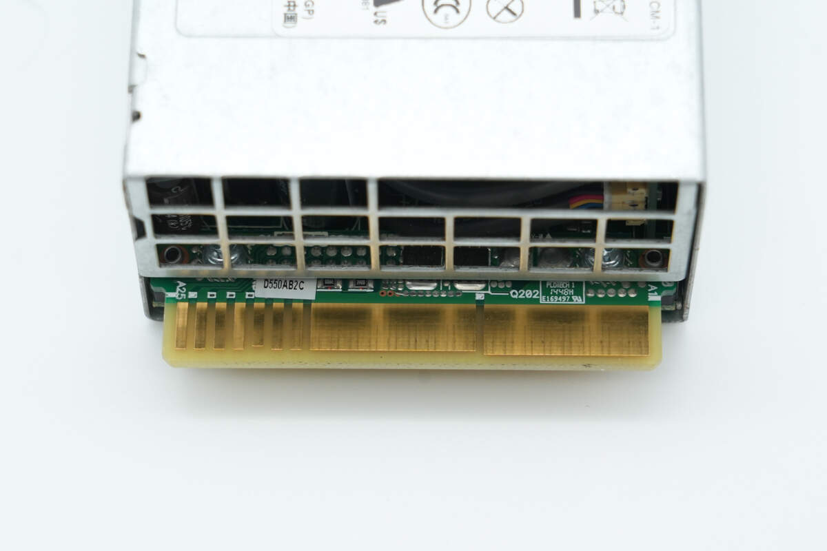
Close-up of the gold-finger connector.
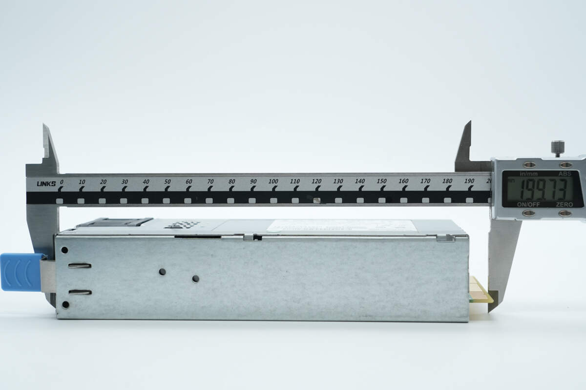
The length of the module is about 200 mm (7.87 inches).
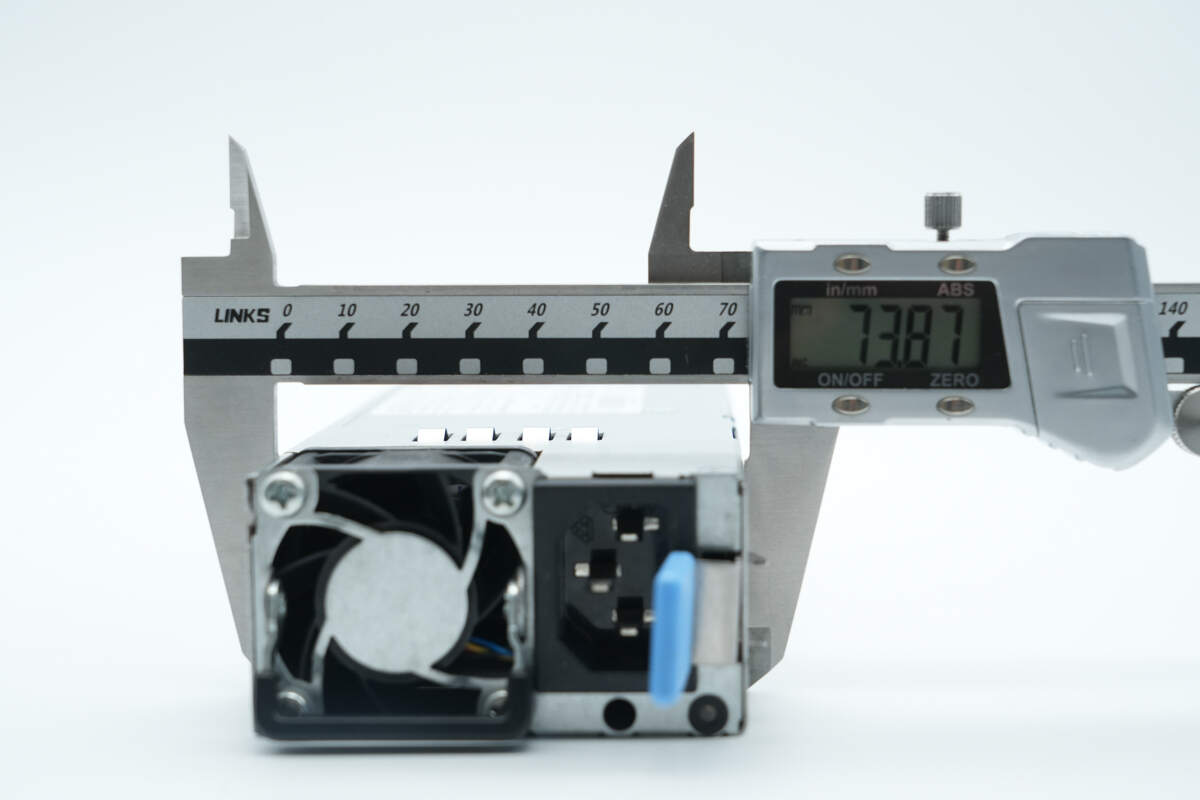
The width is about 73.9 mm (2.91 inches).
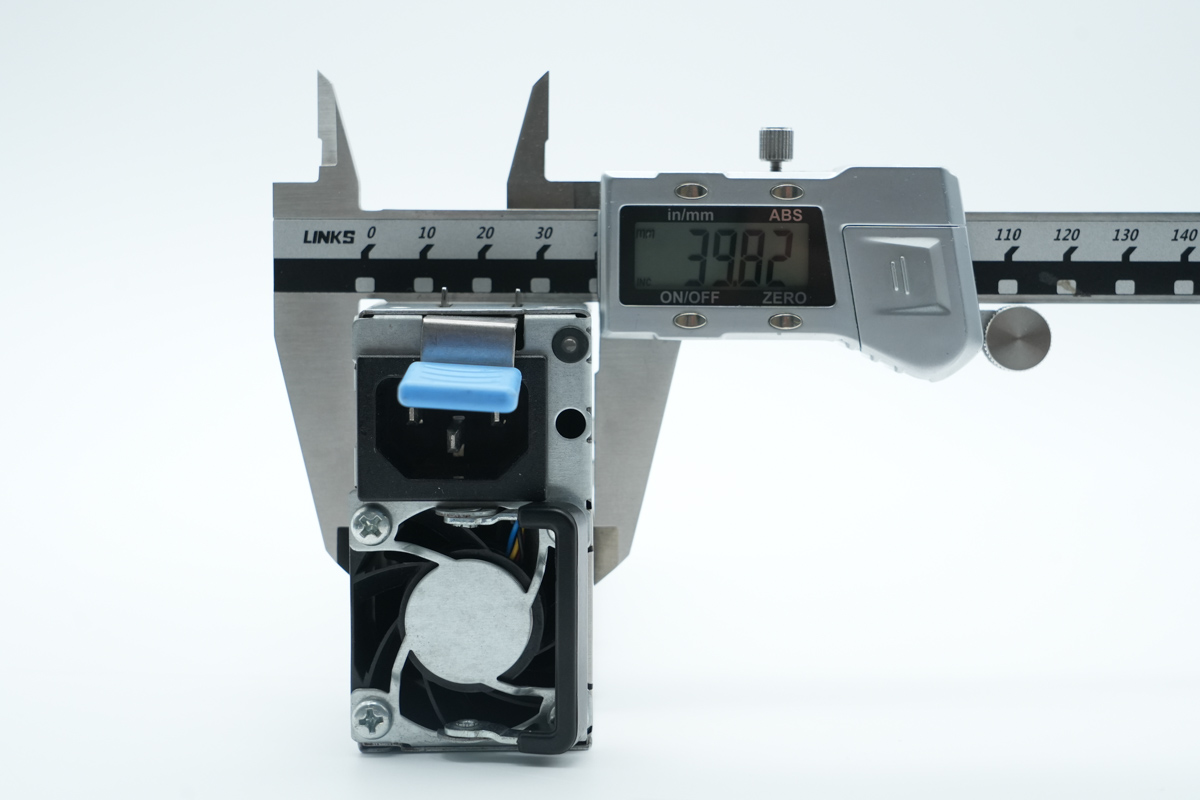
The thickness is about 39.8 mm (1.57 inches).
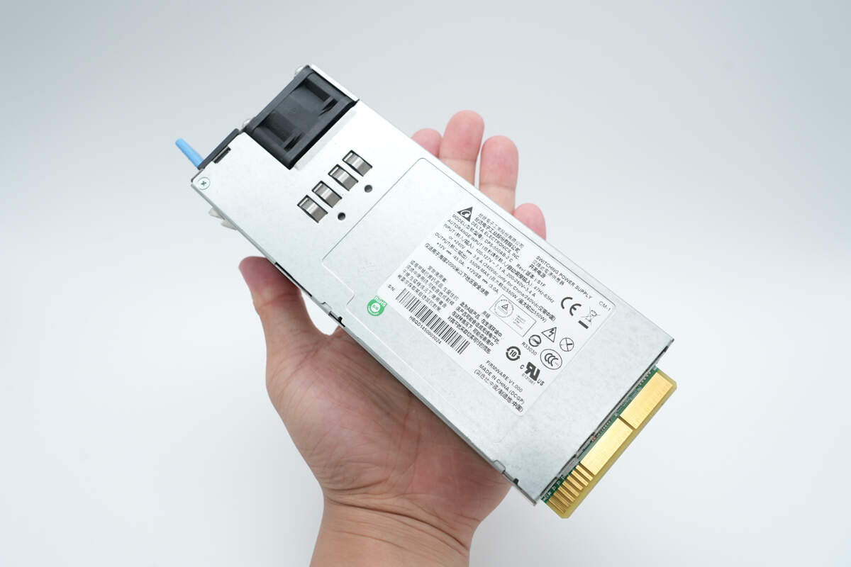
That's how big it is in the hand.
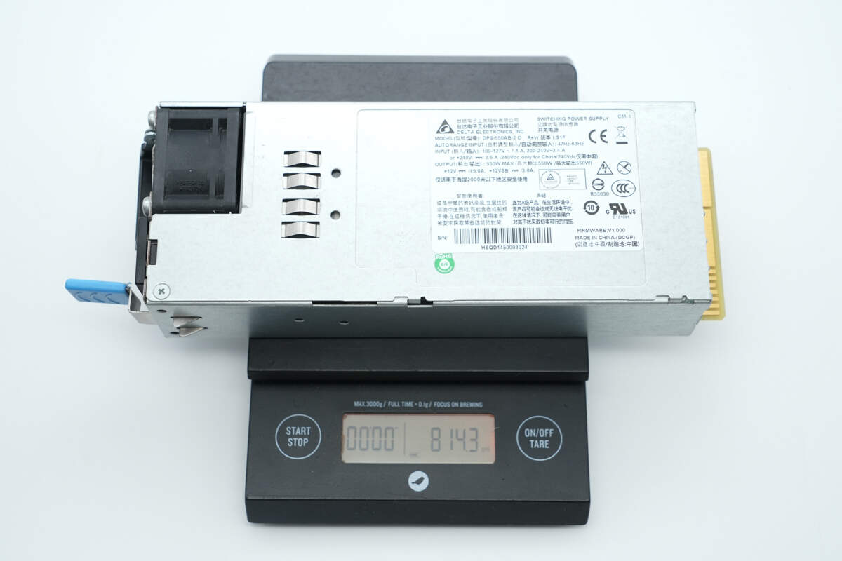
The weight is about 814.3 g (28.72 oz).
Teardown
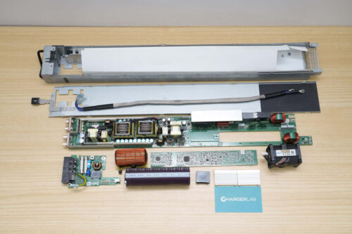
Next, let's take it apart to see its internal components and structure.

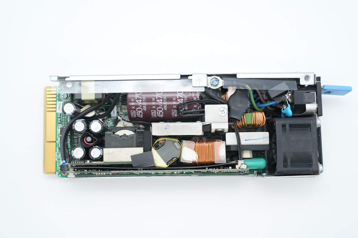
Remove the enclosure. The PCBA module is covered with a transparent Mylar sheet.
The PCBA module is secured with screws.
The LED indicator and cooling fan are connected via connectors.
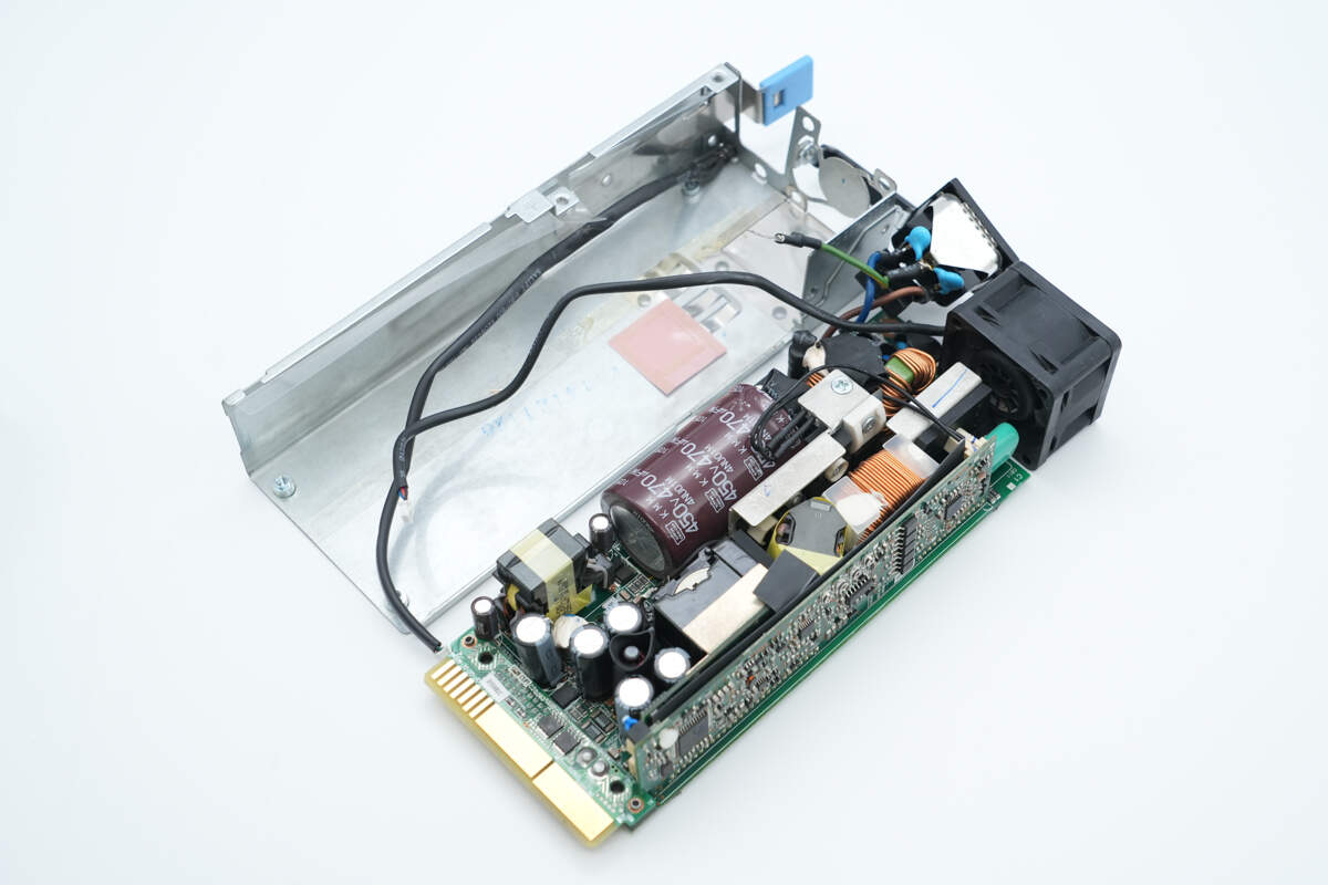
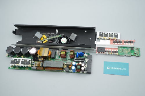
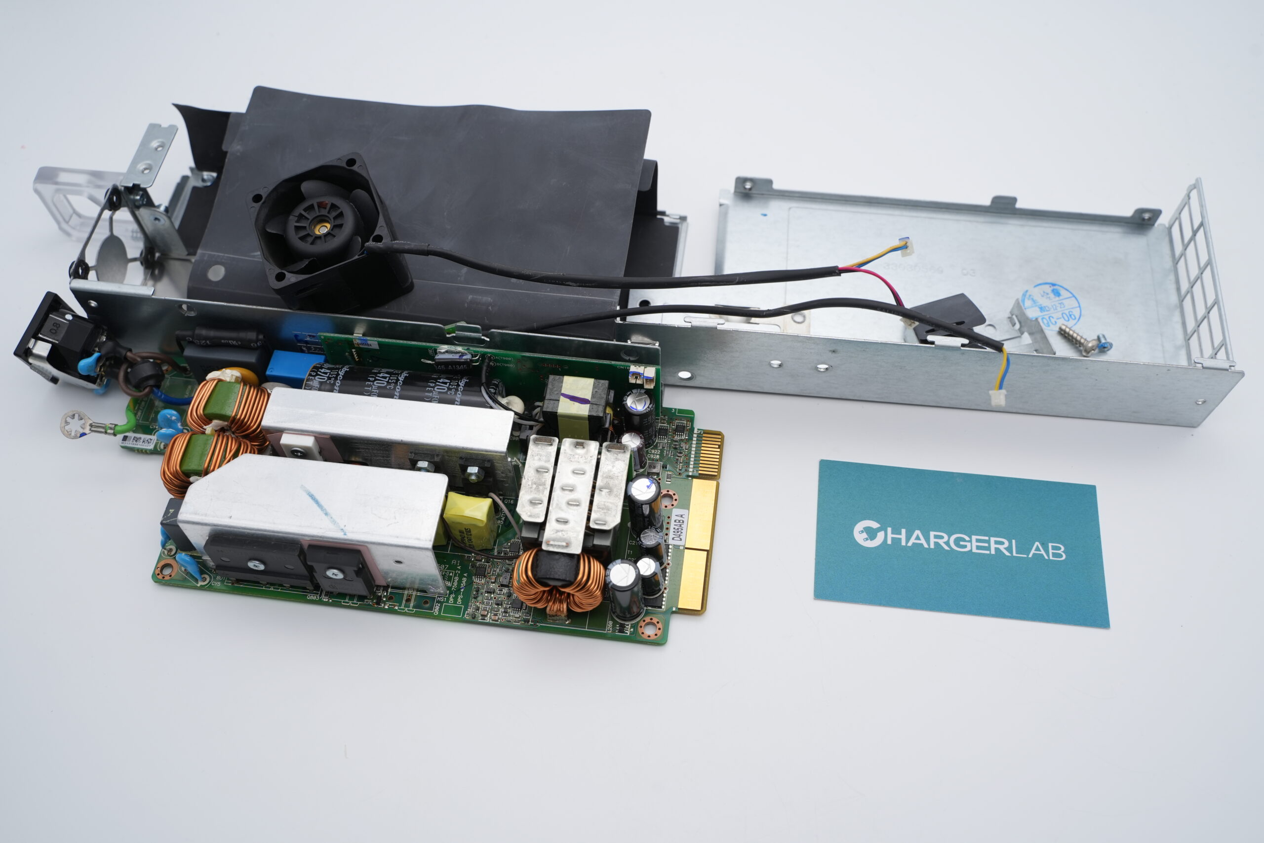
Remove the PCBA module.

Inside the housing, there is a transparent Mylar sheet. The sheet has openings corresponding to the PCB positions and is fitted with a thermal pad.
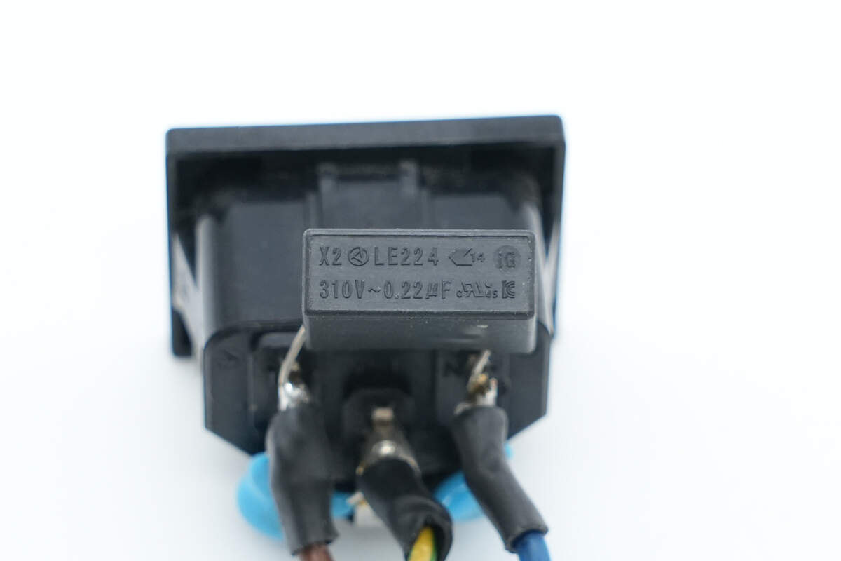
The safety X2 capacitor is from OKAYA, with a specification of 0.22 μF.
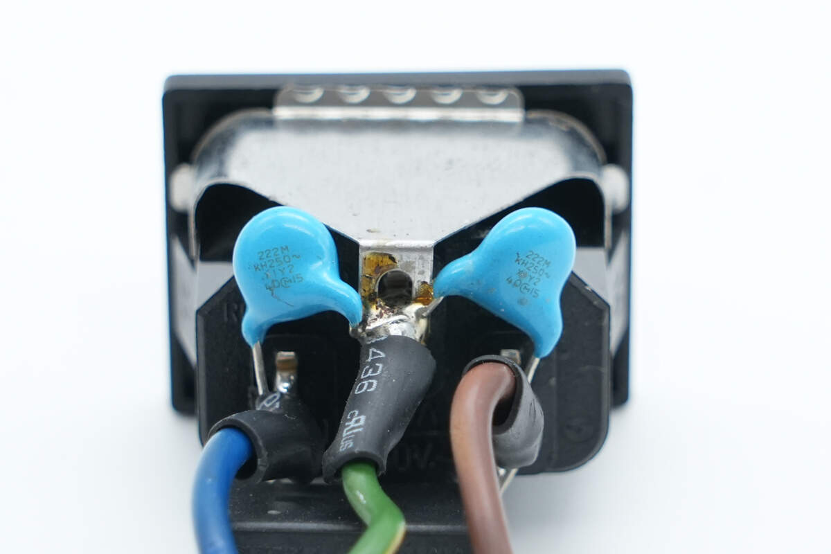
The blue Y capacitor is from MURATA.
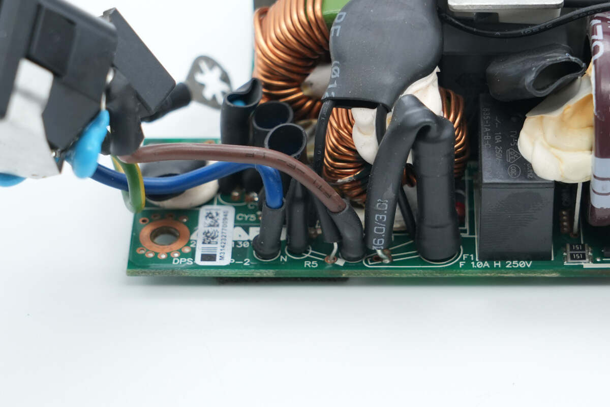
The input wires are insulated with heat shrink tubing.
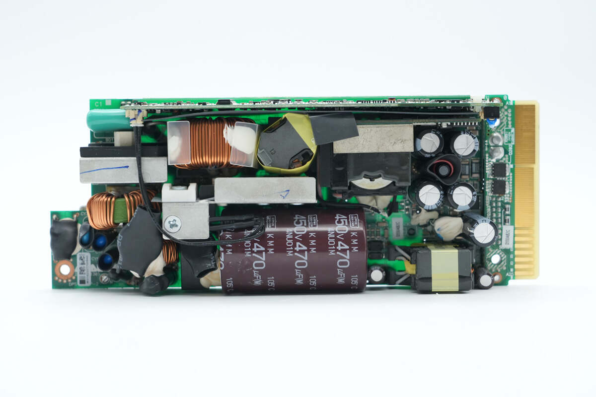
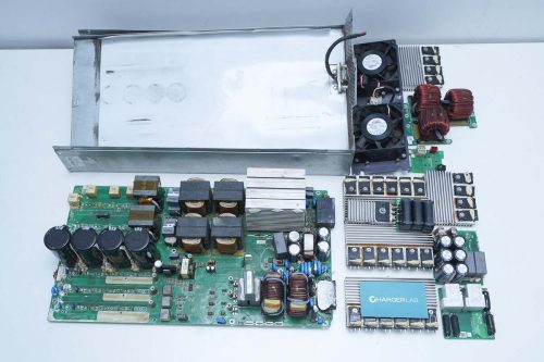
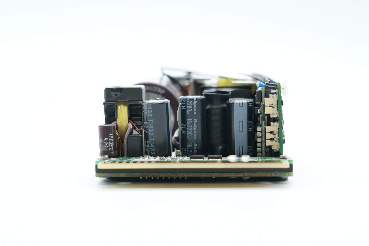
The front side of the PCBA module contains the following components: fuse, Y capacitors, varistor, common mode chokes, relay, thermistor, safety X2 capacitor, bridge rectifier, film capacitor, PFC boost inductor, resonant inductor, PFC MOSFET, LLC MOSFETs, high-voltage filter capacitor, transformer, filter capacitors, filter inductor, and auxiliary power transformer.

On the back side, foam is placed on both sides to prevent foreign objects from entering, and there is also a thermal pad.

The back side is equipped with a current-sensing resistor, LLC controller, standby power MOSFET, synchronous rectifier controller, synchronous rectifiers, and a voltage comparator.
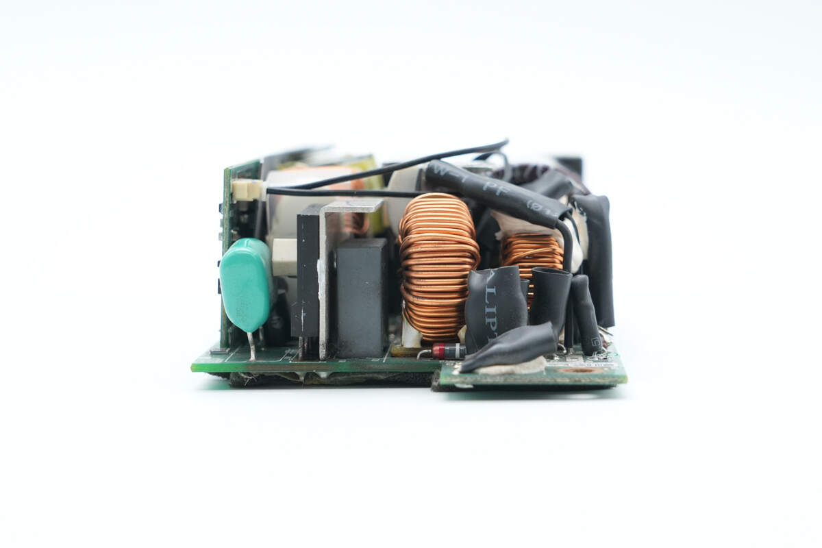
The input side is equipped with a fuse, varistor, common mode choke, safety X2 capacitor, bridge rectifier, and film capacitor.
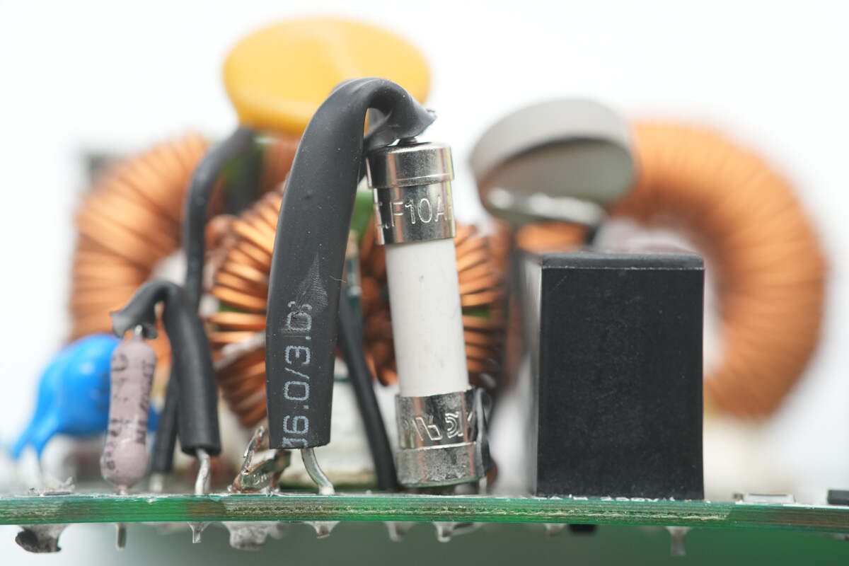
The input fuse has a rating of 10 A.
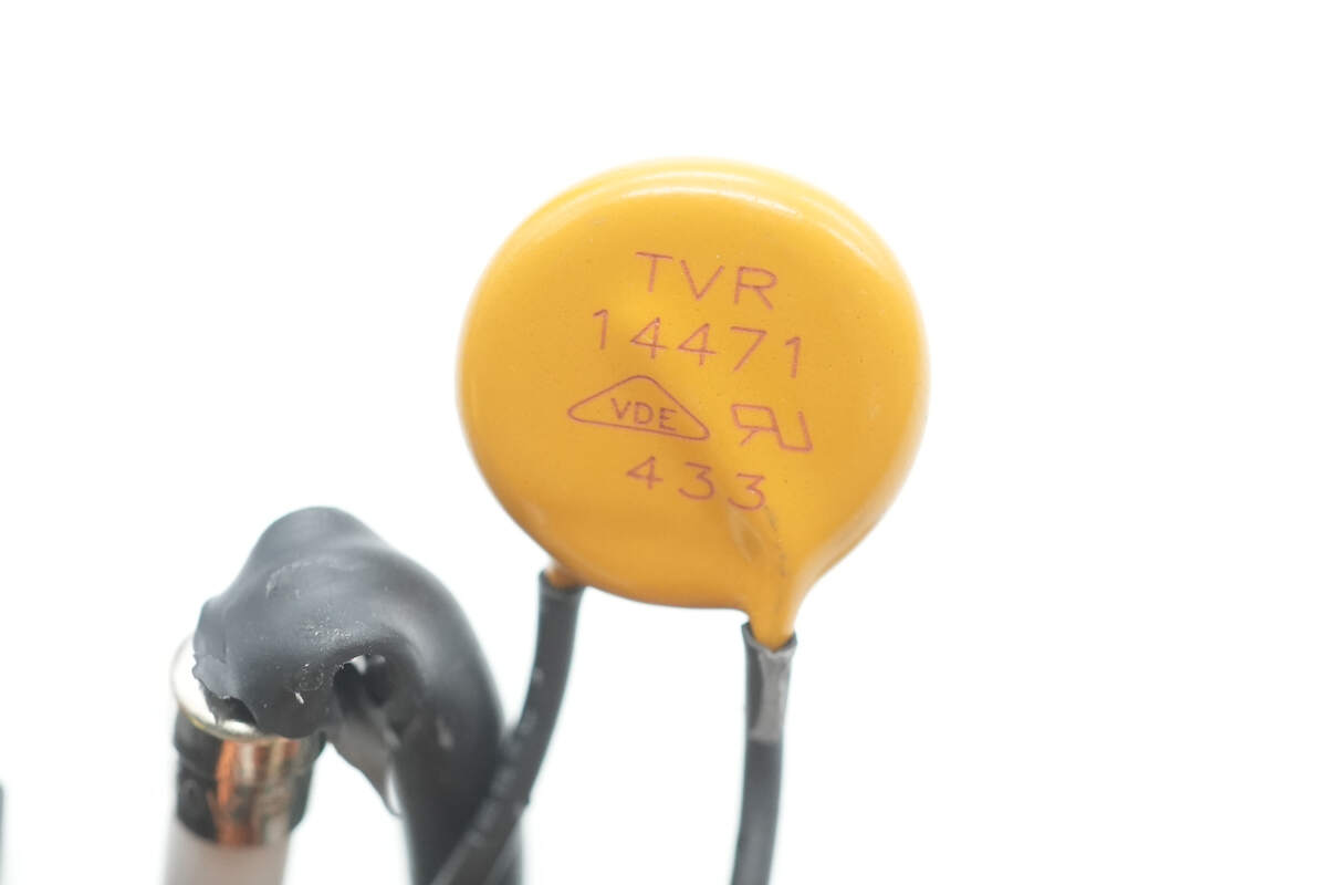
The varistor is model TVR14471 and is used to absorb overvoltage surges.
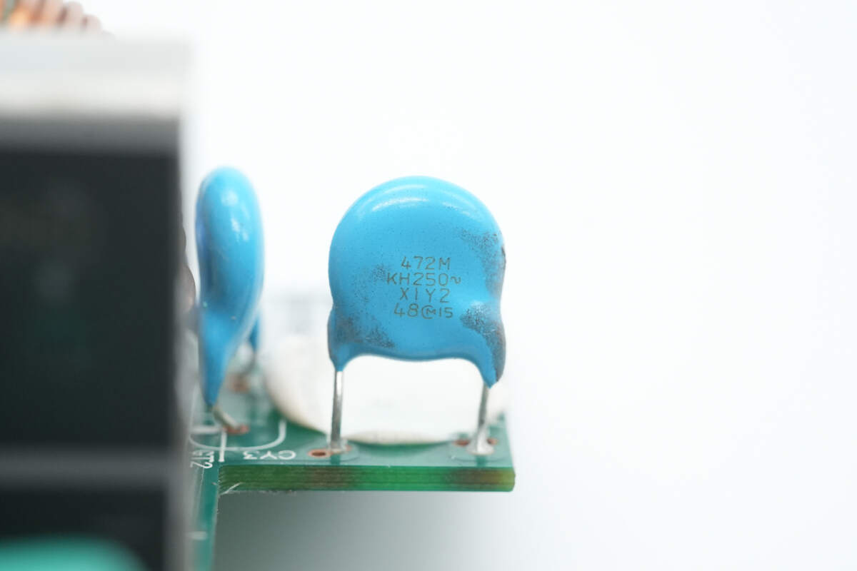
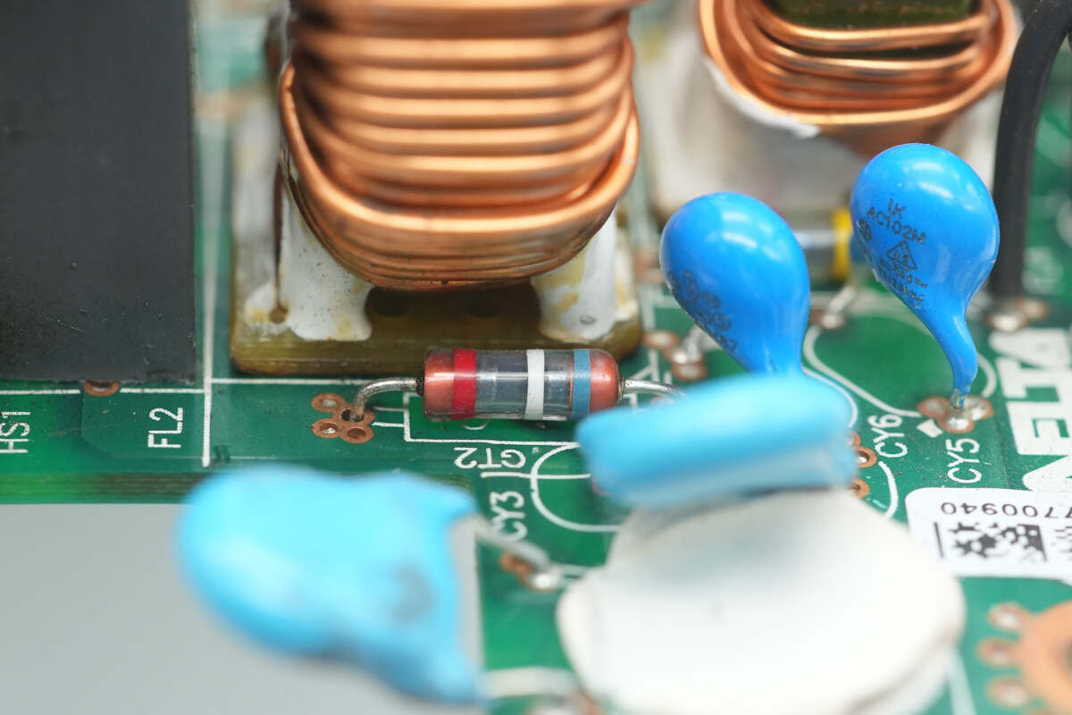
The blue Y capacitor is from MURATA.
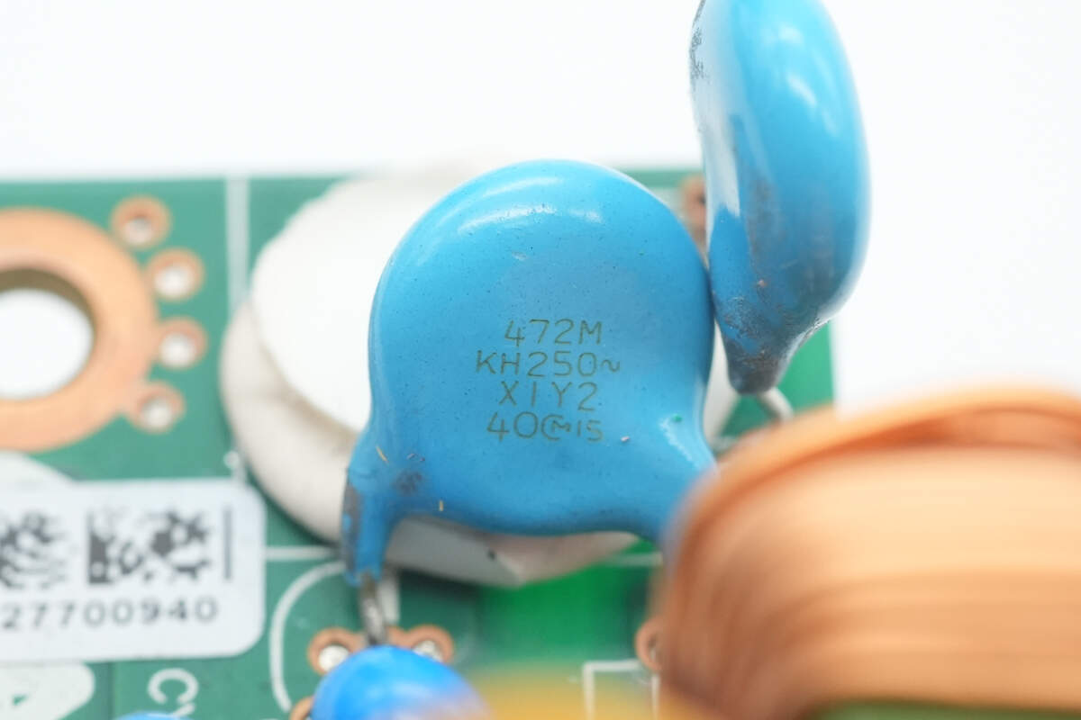
Another Y capacitor is also from MURATA.

Two Y capacitors are sourced from Walsin.
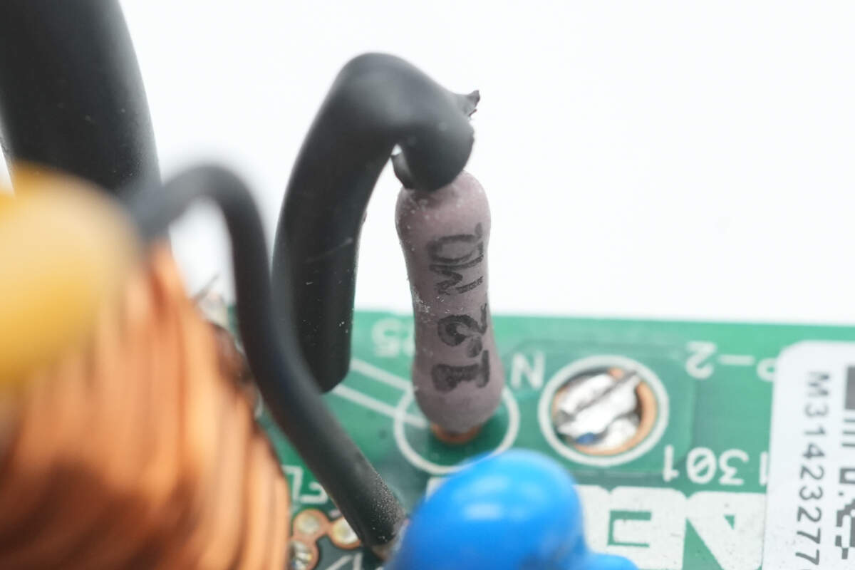
Close-up of the discharge resistor for the X capacitor.
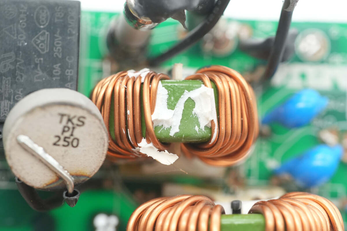
The common mode choke is wound with enameled wire.
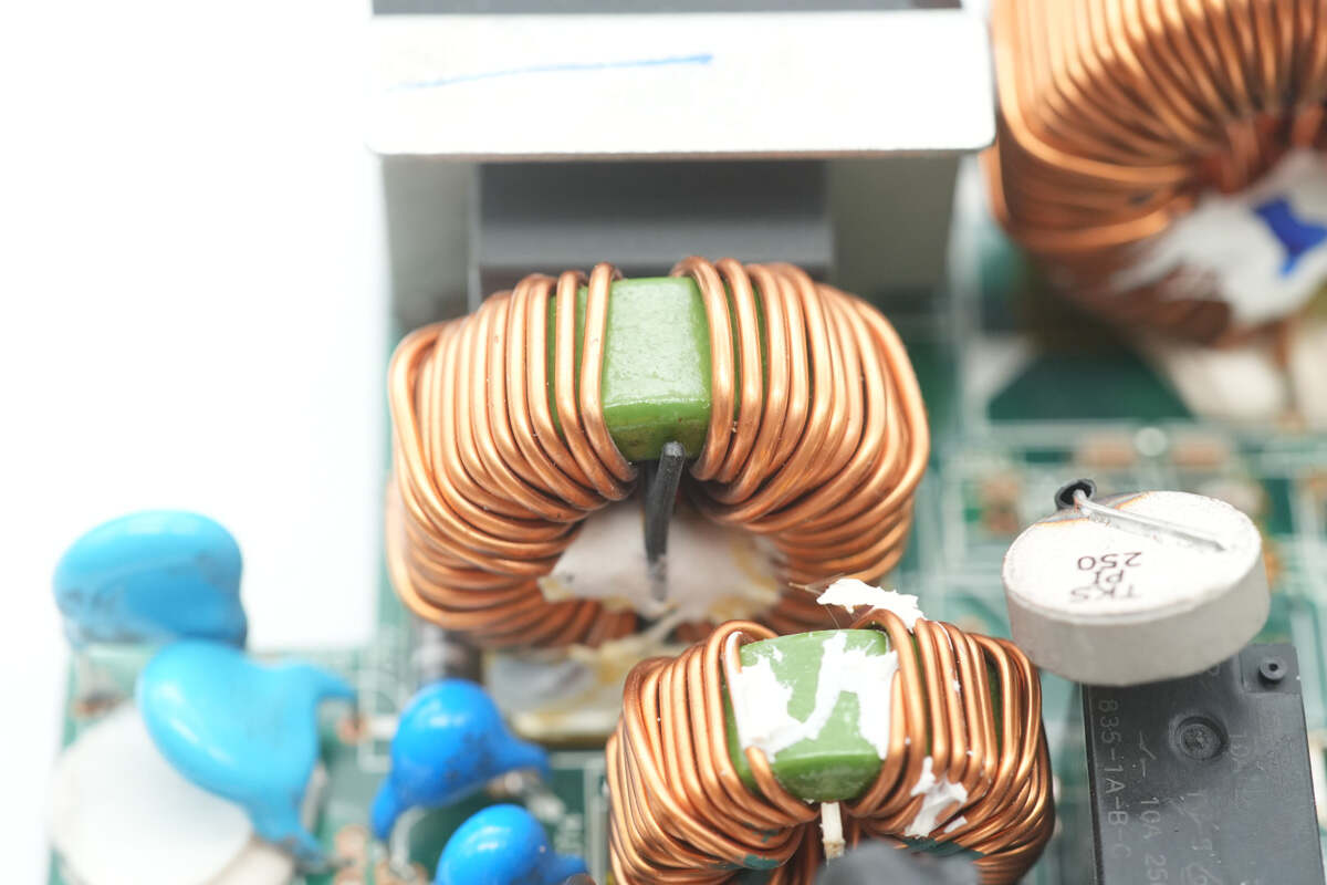
Another common mode choke is also wound with enameled wire.
Gas discharge tubes are installed on both sides of the common mode chokes.
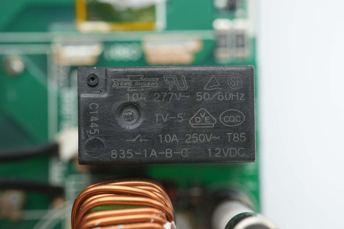
The relay is from SongChuan, model 835-1A-B-C, with a contact rating of 10 A 250 V and a coil voltage of 12 V, used for the short-circuit thermistor.
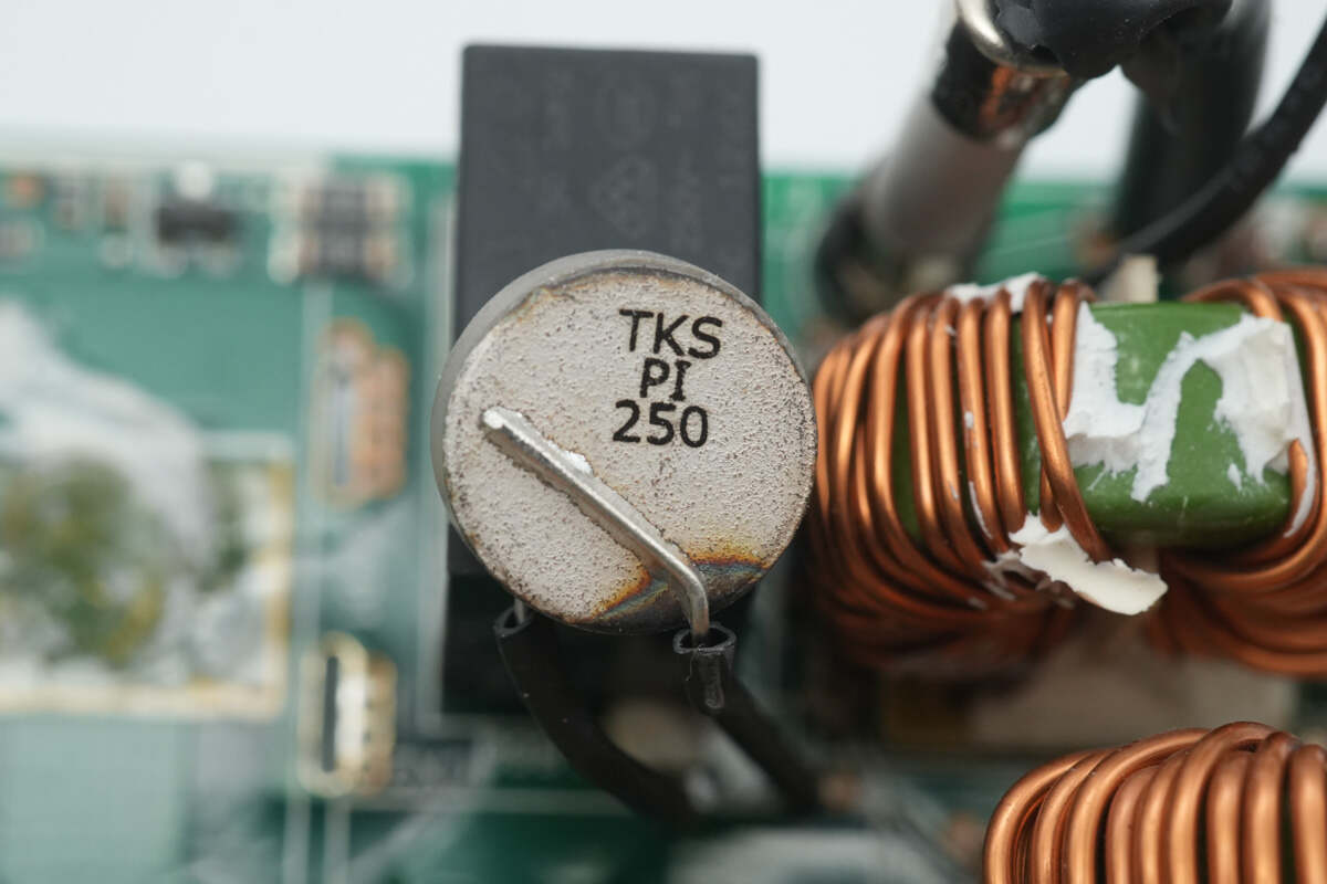
The thermistor is from Thinking, marked with PI 250.
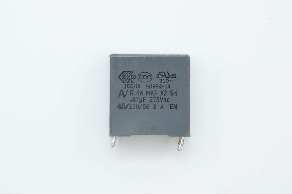
The safety X2 capacitor has a specification of 0.47 μF.
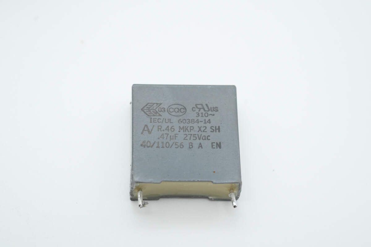
Another capacitor has the same specification of 0.47 μF.

The bridge rectifier is from Shindengen, model D25XB60, rated at 25 A 600 V, and comes in a 5S package.
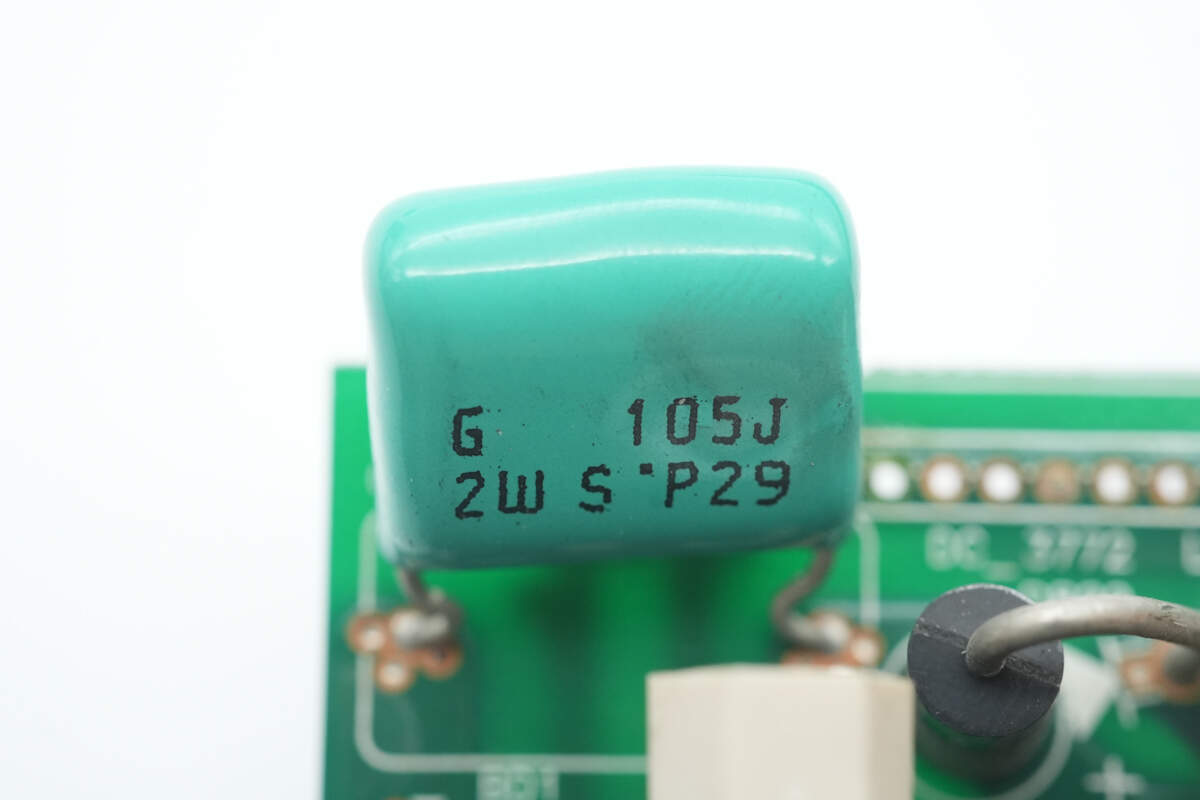
The film capacitor is from SHINYEI, with a specification of 450 V, 1 μF.
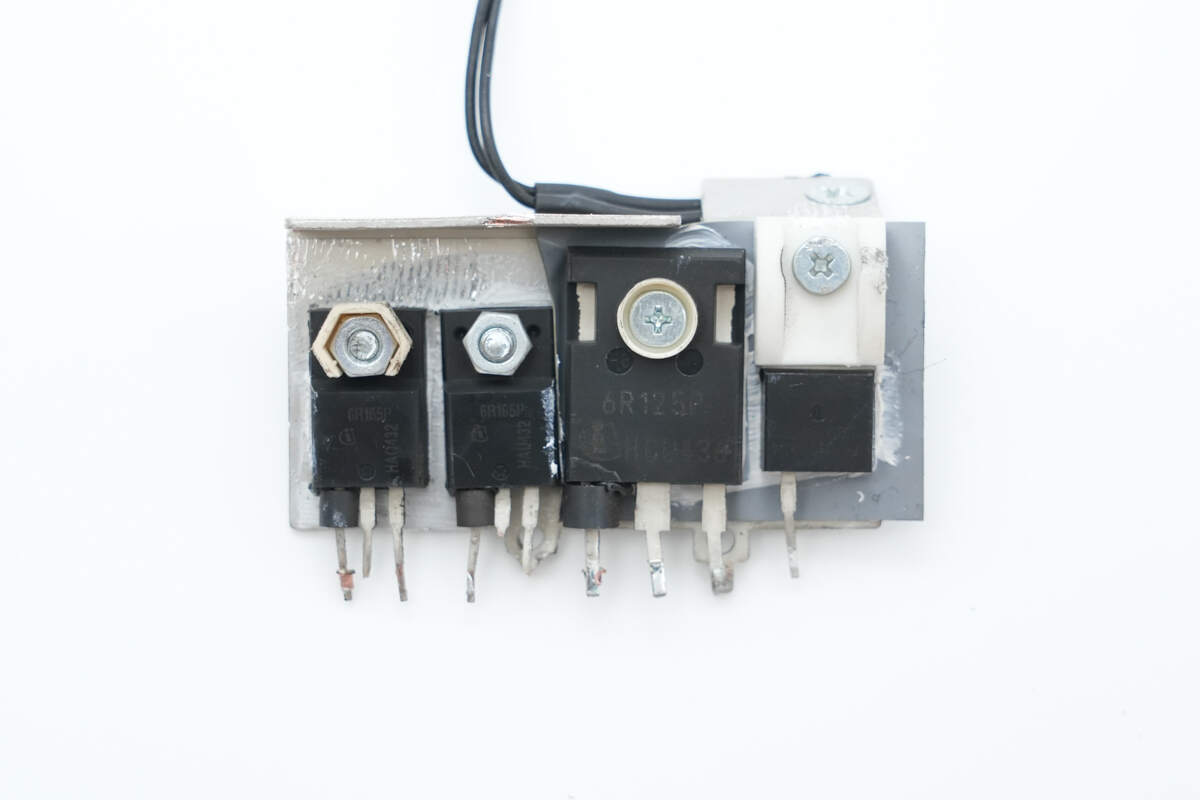
The front side of the heatsink is equipped with LLC MOSFETs, PFC MOSFET, and PFC rectifier.
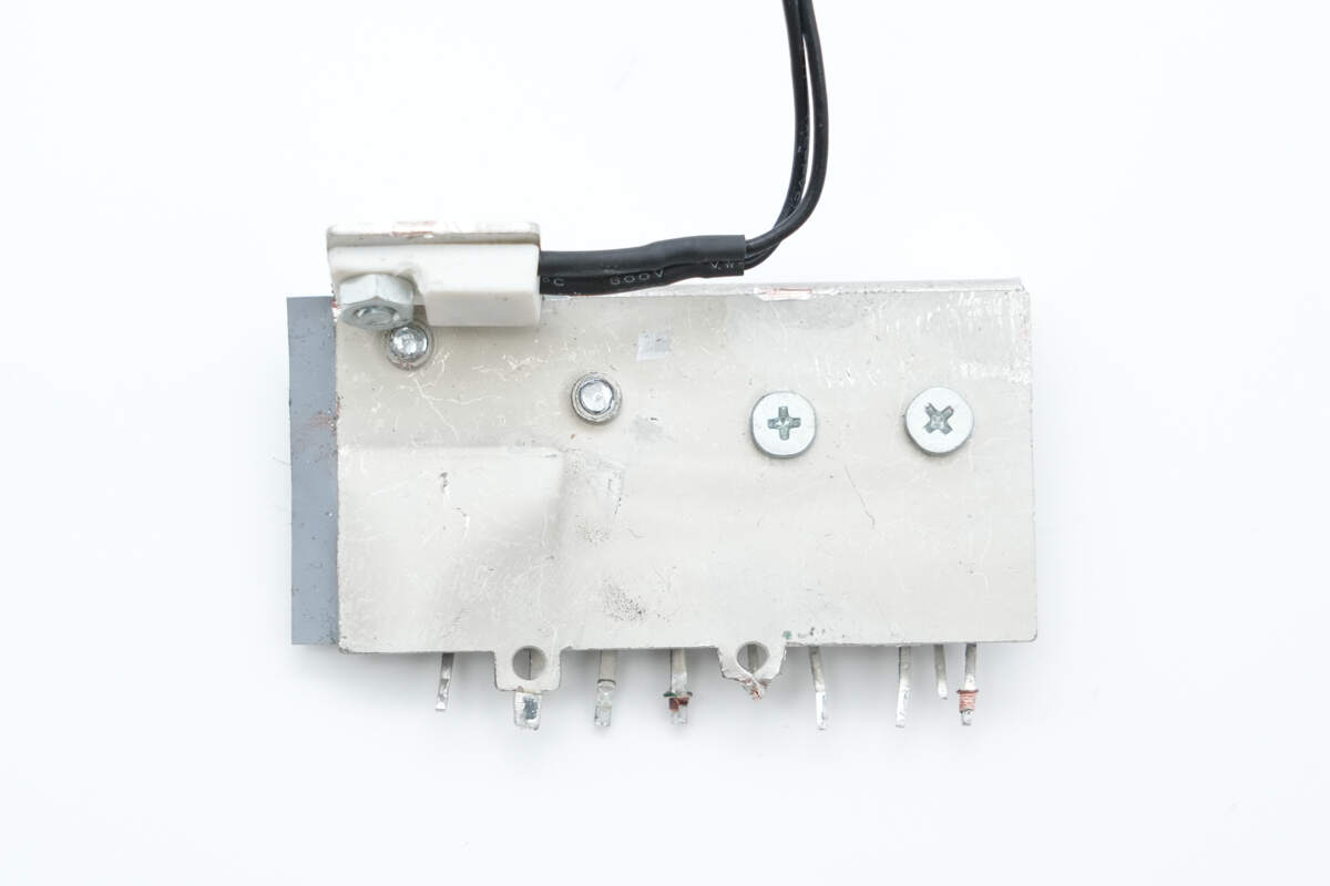
On the back side, there is a thermistor used for temperature rise detection.
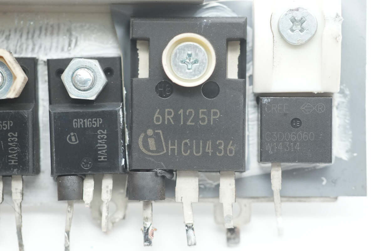
The PFC MOSFET is from Infineon, marked 6R125P, model IPW60R125CP. It is an NMOS with a voltage rating of 650 V, an on-resistance of 125 mΩ, and comes in a TO-247-3-1 package.
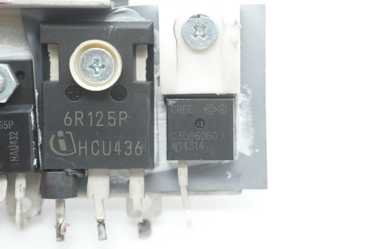
The PFC rectifier is from Wolfspeed, model C3D06060A. It is a silicon carbide (SiC) diode rated at 600 V, 6 A, and comes in a TO-220-2 package.
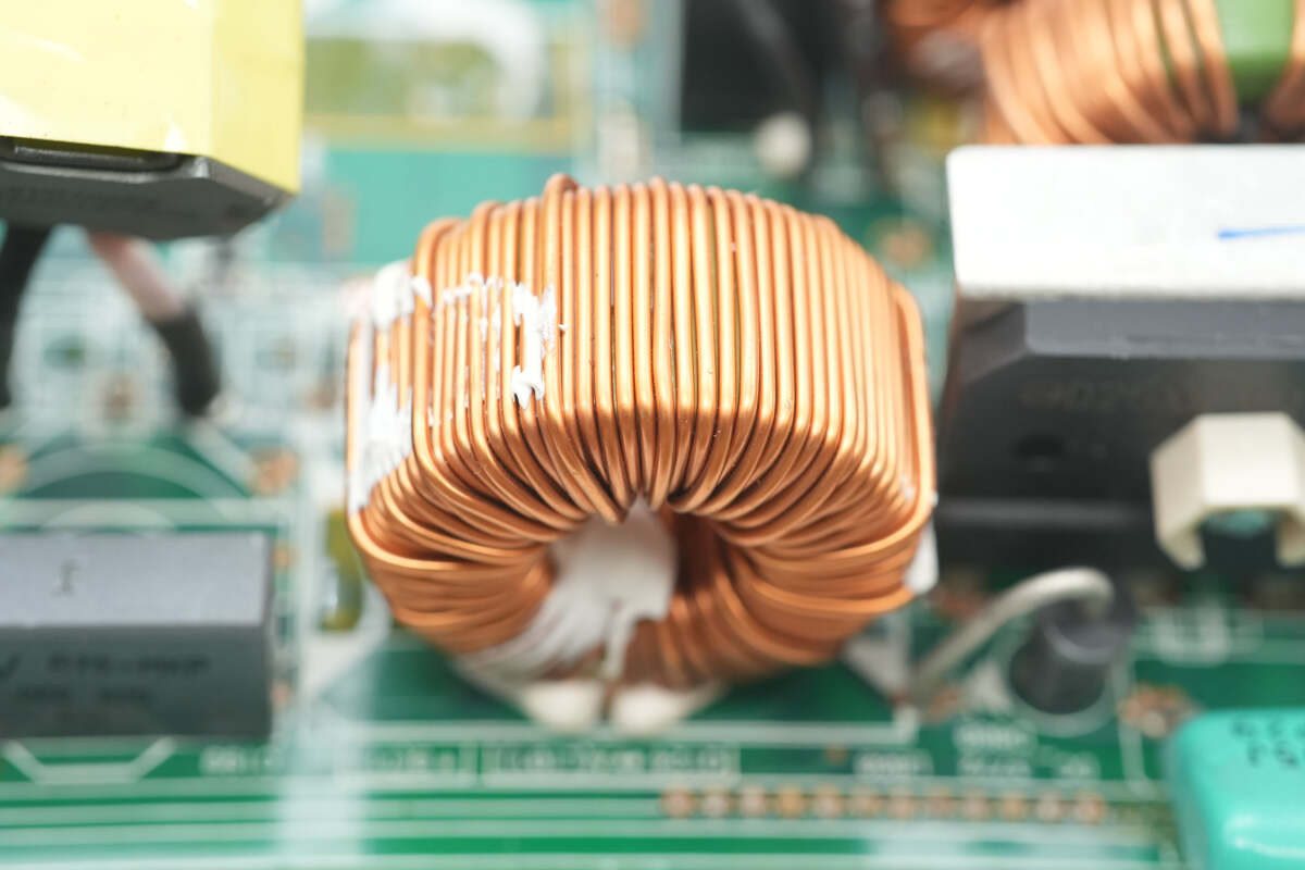
The PFC boost inductor is wound with enameled wire.
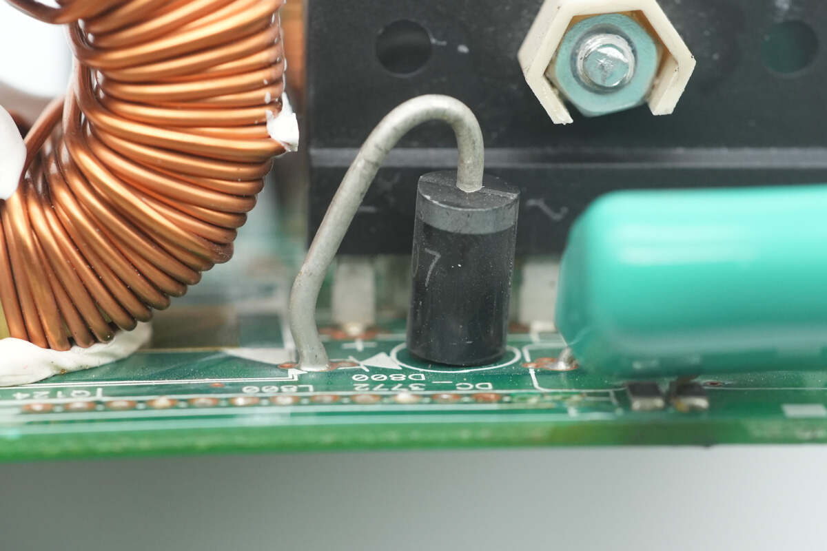
Close-up of the PFC bypass diode.
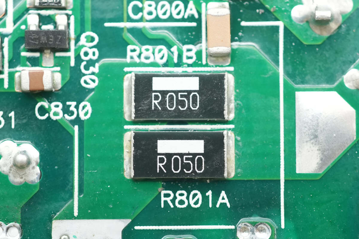
Two 50 mΩ resistors are connected in parallel to sense the current of the PFC MOSFET.

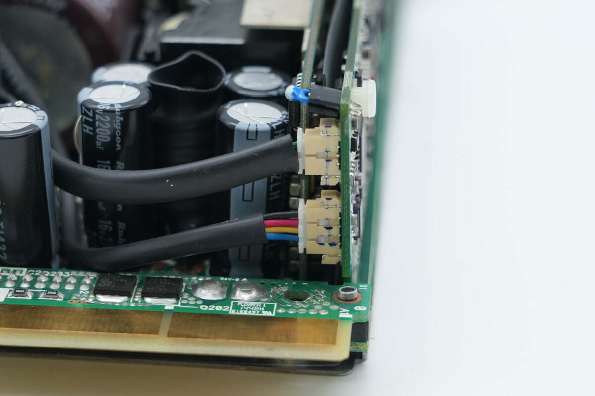
The high-voltage filter capacitor and standby power transformer are soldered on the side of the PCBA module.
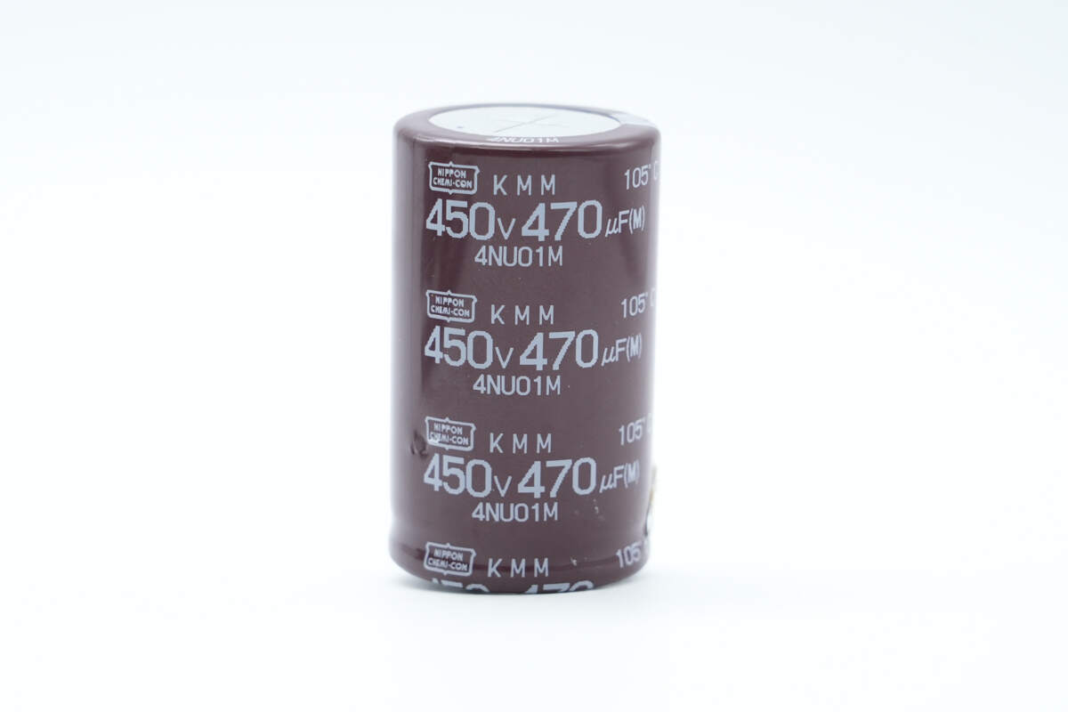
The high-voltage filter capacitor is from NCC, part of the KMM series of long-life electrolytic capacitors, with a specification of 450 V, 470 μF.
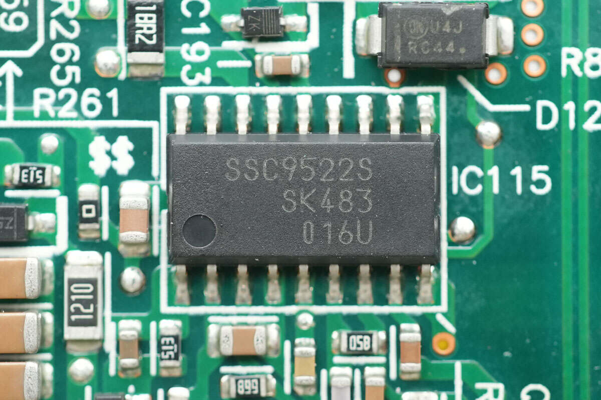
The LLC controller is from SanKen, model SSC9522S, designed for half-bridge resonant switching power supplies. It features a built-in floating gate driver for high-side MOSFETs, enabling high-efficiency, low-noise, and cost-effective power supply solutions with minimal external components. It comes in an SOP18 package.
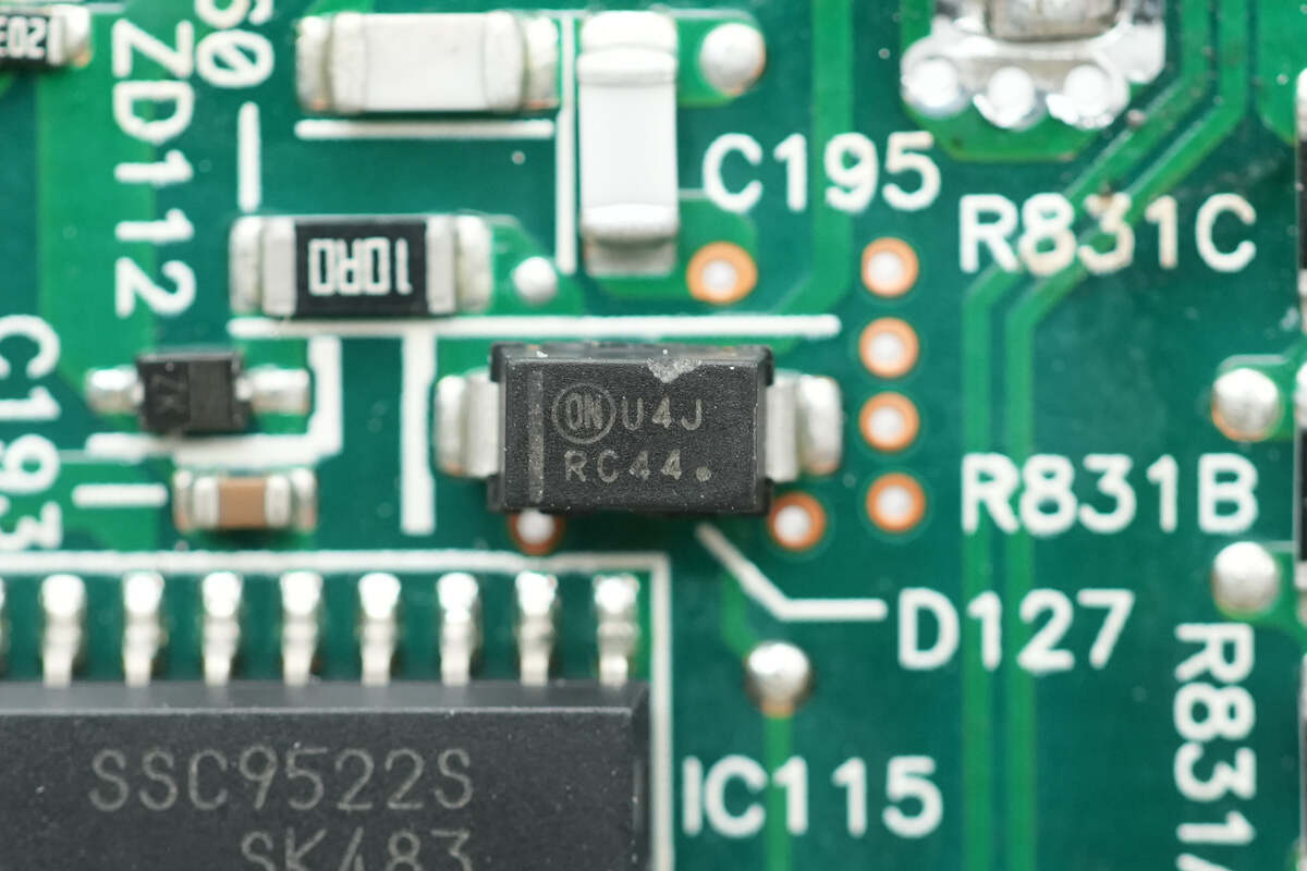
The ultra-fast recovery diode is from Onsemi, marked U4J, model MURA160, rated at 600 V, 1 A, and comes in an SMA package.
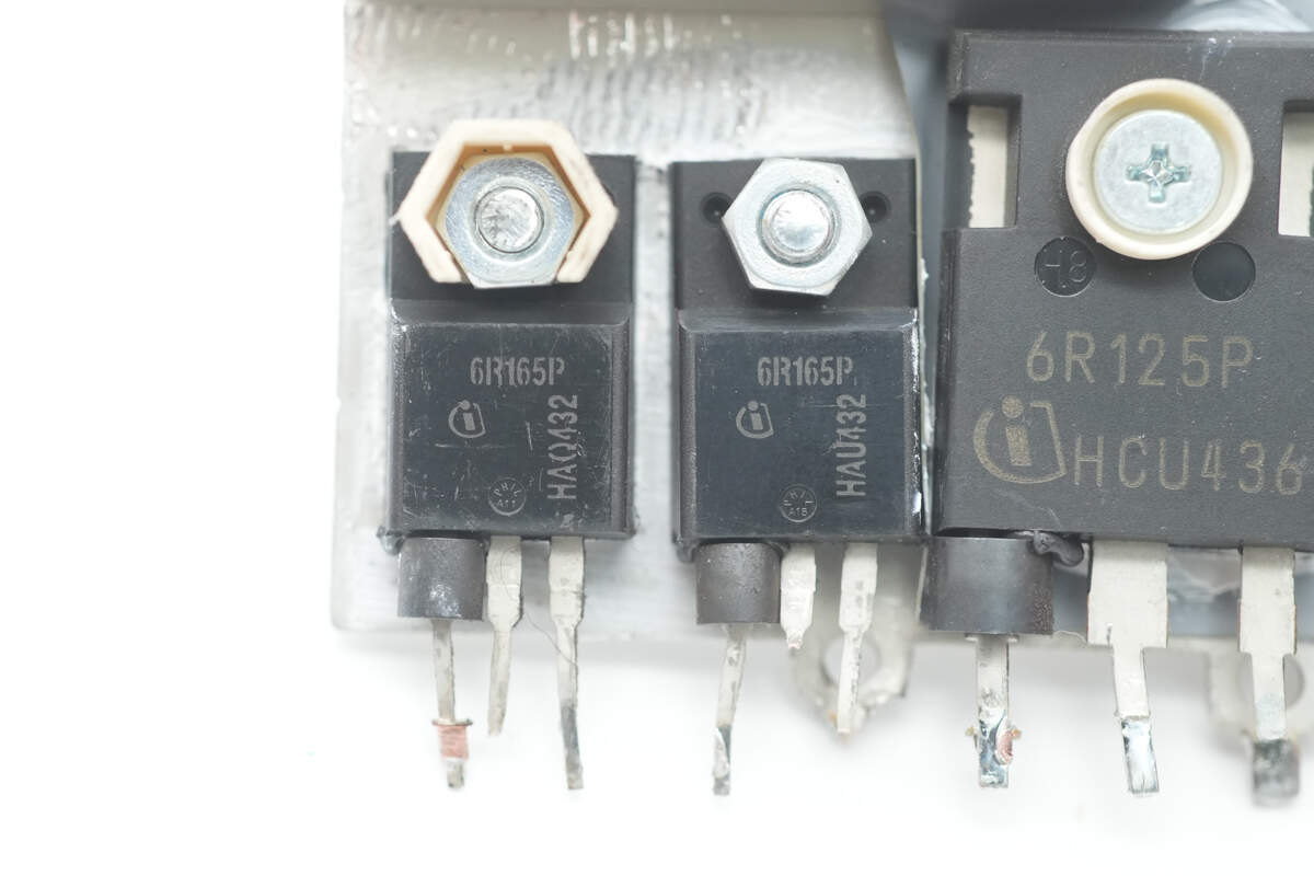
The LLC MOSFETs are from Infineon, marked 6R165P, model IPA60R165CP. They are NMOS with a voltage rating of 650 V, on-resistance of 165 mΩ, and come in a TO-220 package.
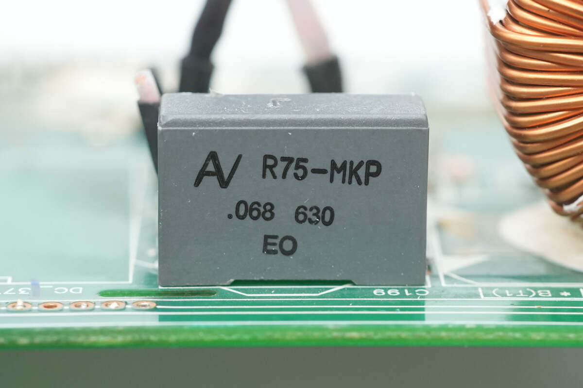
The resonant capacitor has a specification of 0.068 μF, 630 V.
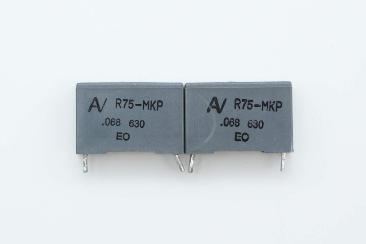
The other two resonant capacitors have the same specification of 0.068 μF, 630 V.
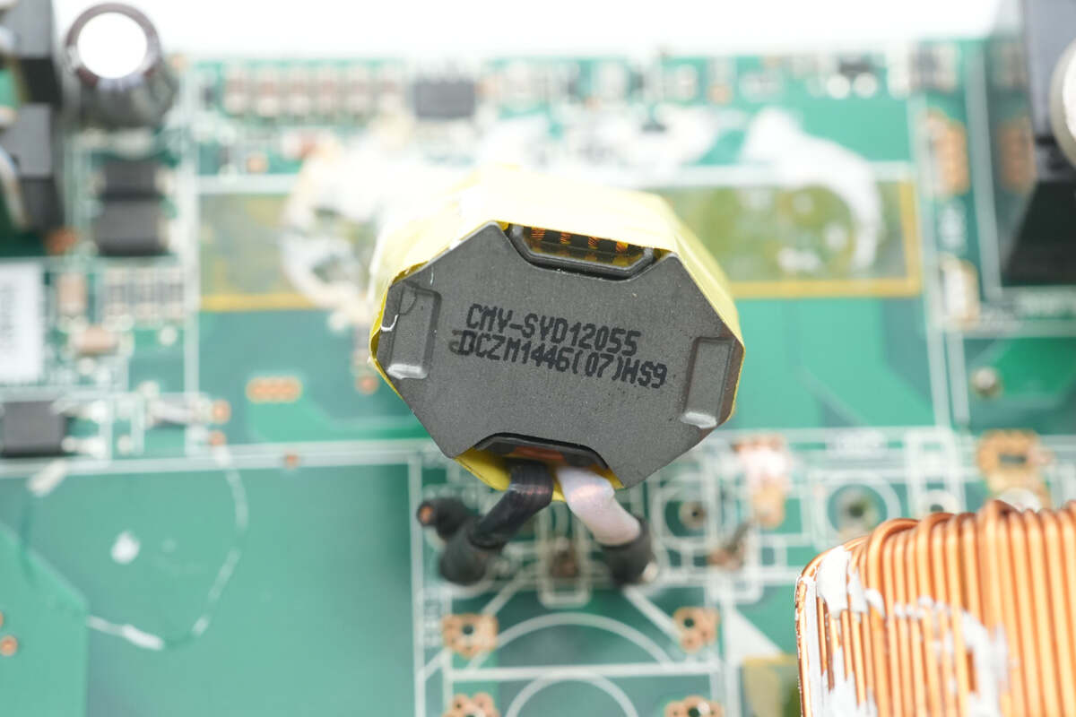
The resonant inductor is wound with Litz wire.
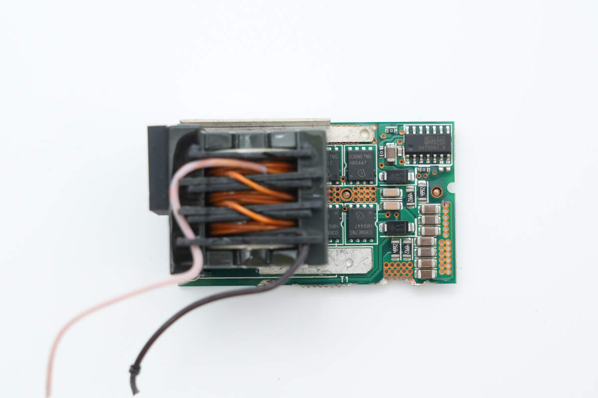
The synchronous rectifier PCB is equipped with a transformer, synchronous rectifier controller, and synchronous rectifiers.
Copper bars are soldered on the back side to enhance current-carrying capacity.

The secondary of the transformer is soldered with copper strips.
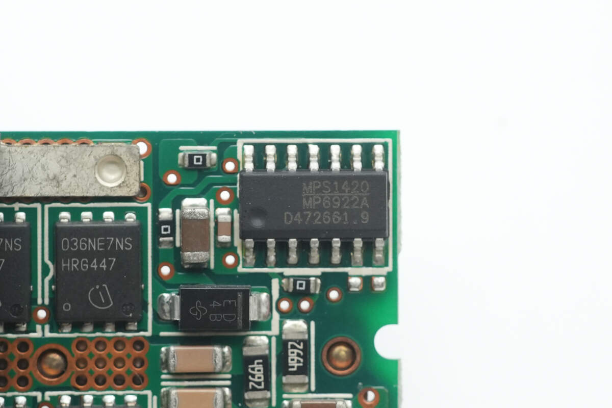
The synchronous rectifier controller is from MPS, model MP6922A, designed for LLC synchronous rectification. It supports CCM and DCM operating modes, standard and logic-level MOSFETs, an operating voltage range of 8–24 V, and light-load mode. It comes in an SOIC14 package.
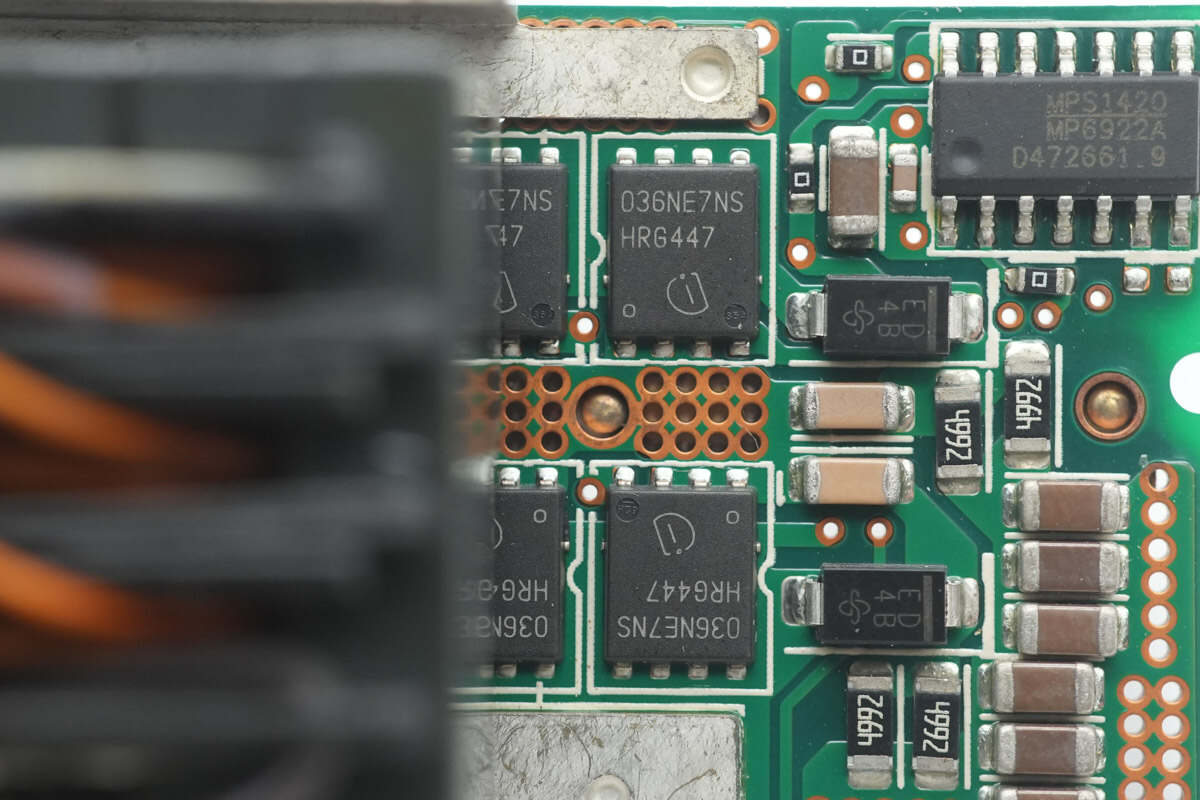
The synchronous rectifiers are from Infineon, model BSC036NE7NS3 G. They are NMOS with a voltage rating of 75 V, on-resistance of 3.6 mΩ, and come in a TDSON-8 package.
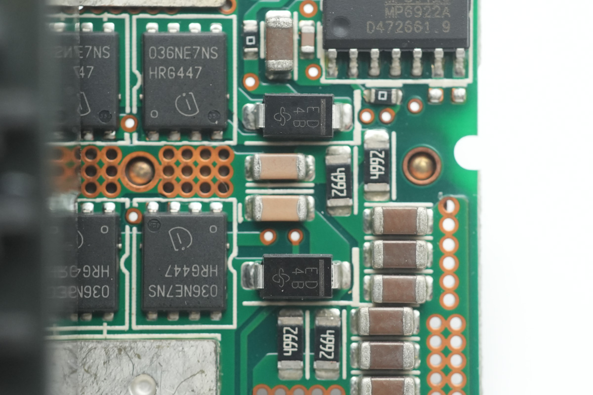
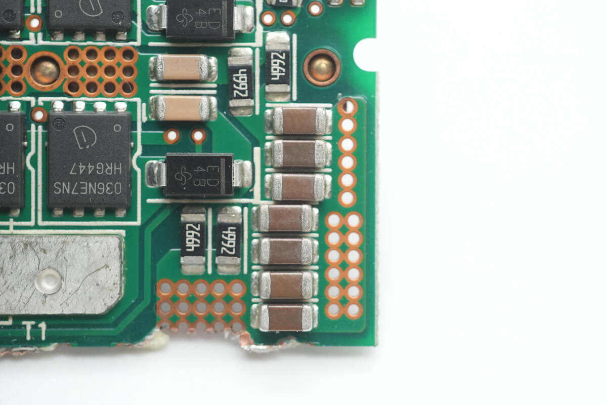
Two rectifier diodes are from VISHAY, marked ED, model ES1D, and come in an SMA package.
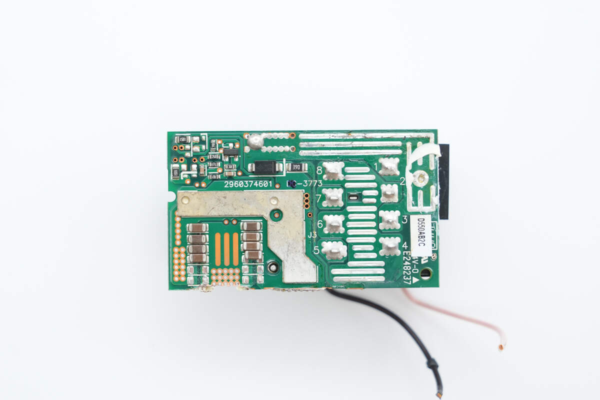
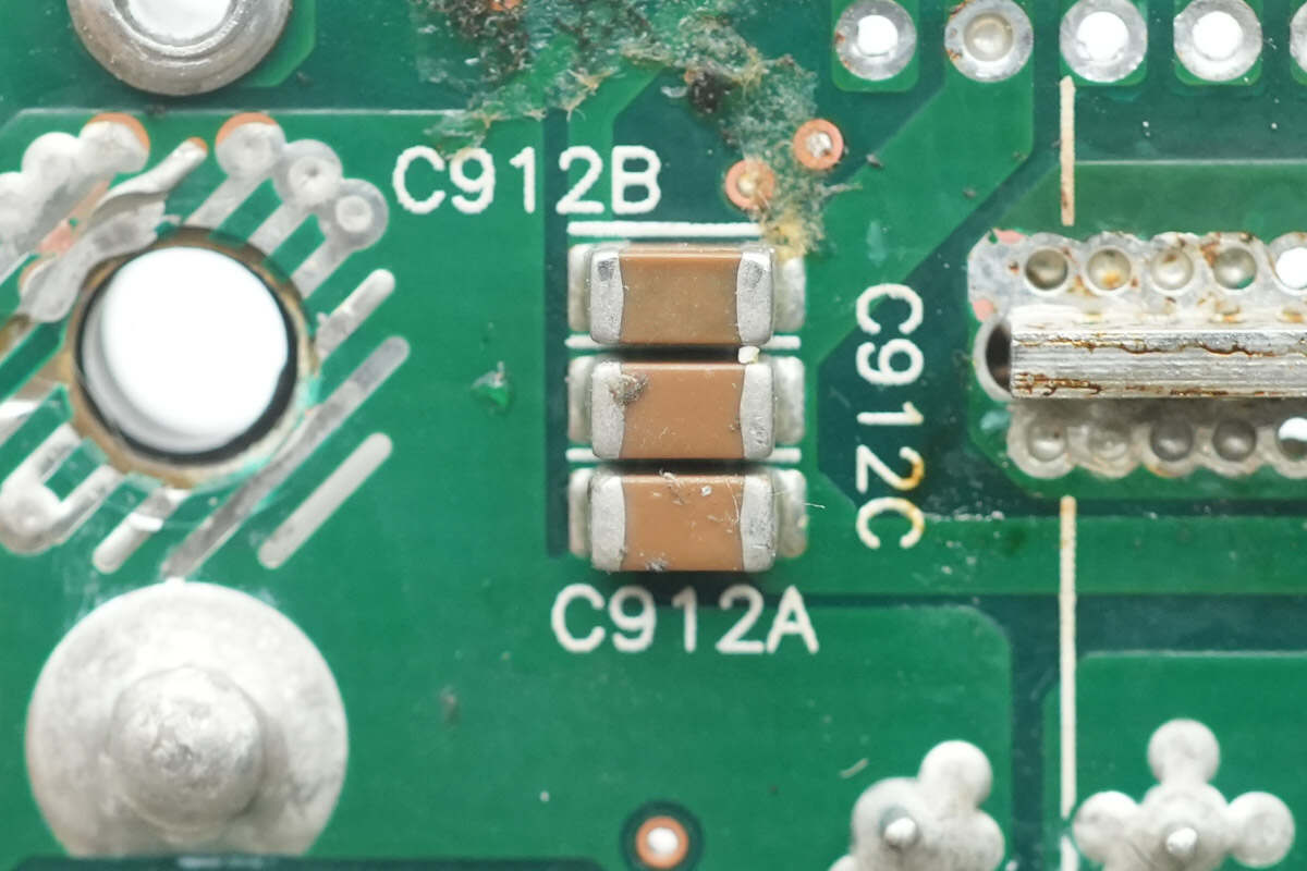
Close-up of the MLCC capacitors.
There are also MLCC capacitors on the back side.
The output side is equipped with a standby power transformer, filter capacitors, and a filter inductor. The filter inductor is insulated with heat shrink tubing.
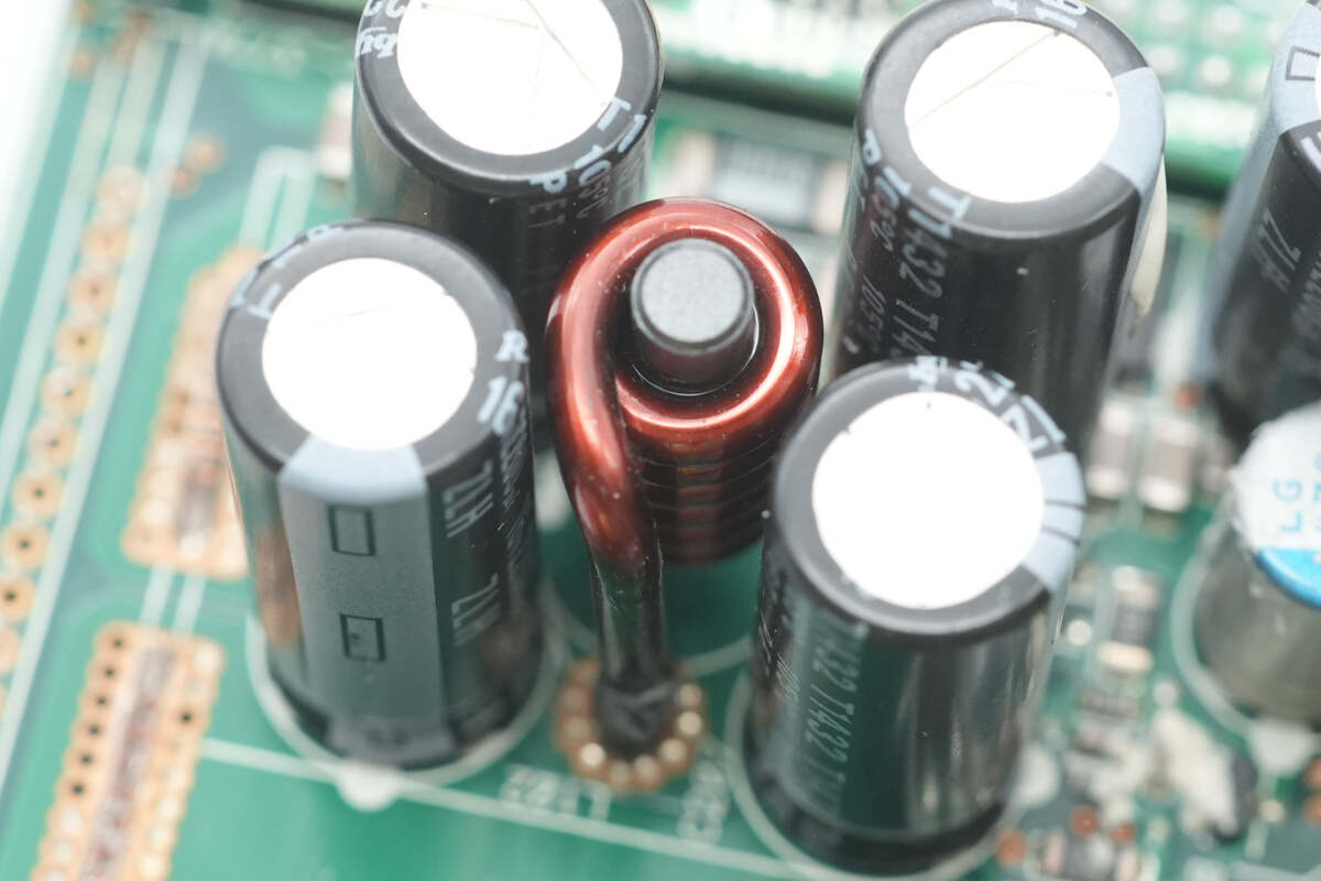
Four filter capacitors are arranged with a filter inductor in the middle.
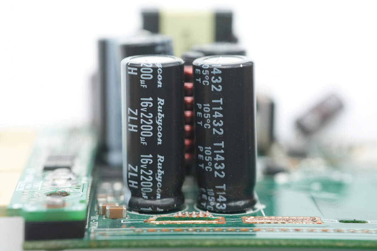
The filter capacitors are from Rubycon, each rated at 16 V, 2200 μF.

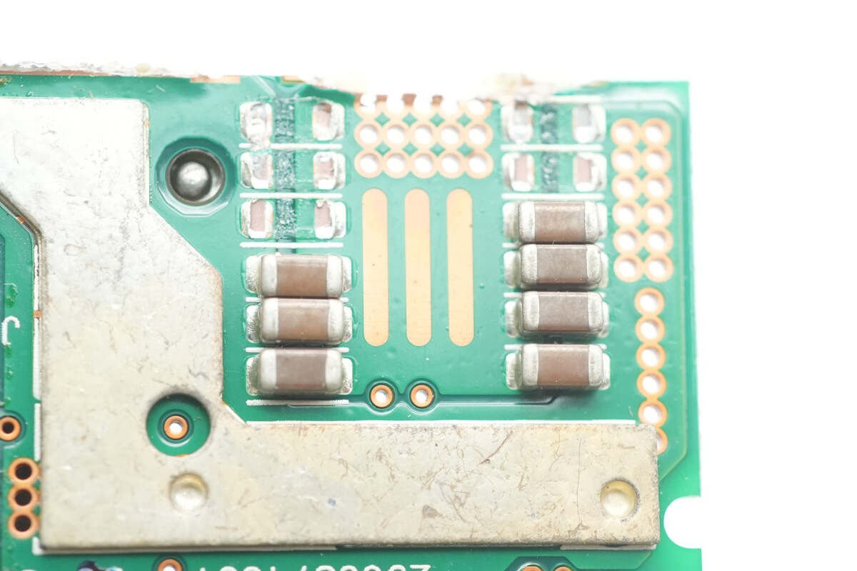
These MLCC capacitors are connected in parallel with electrolytic capacitors for output filtering.
Close-up of another set of MLCC capacitors.
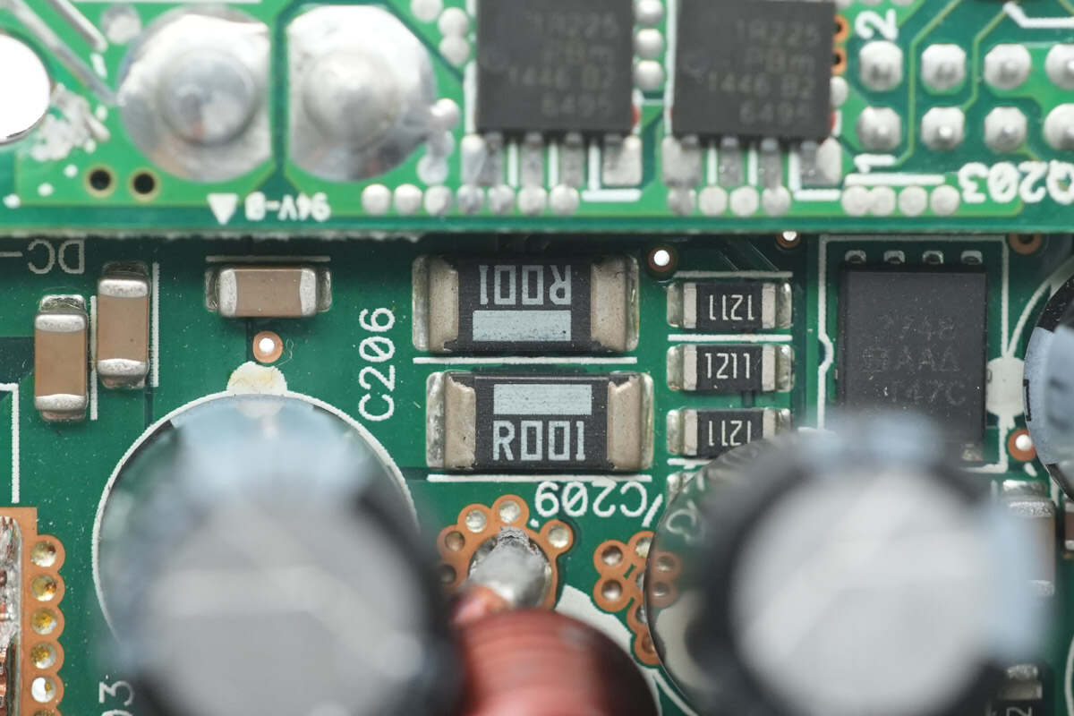
Two 1 mΩ resistors are connected in parallel to sense the output current.

The current-sensing chip is from TI, marked CEU, model INA211. It is a bidirectional high-precision current-sense amplifier, supports up to 26V and comes in an SC70 package.

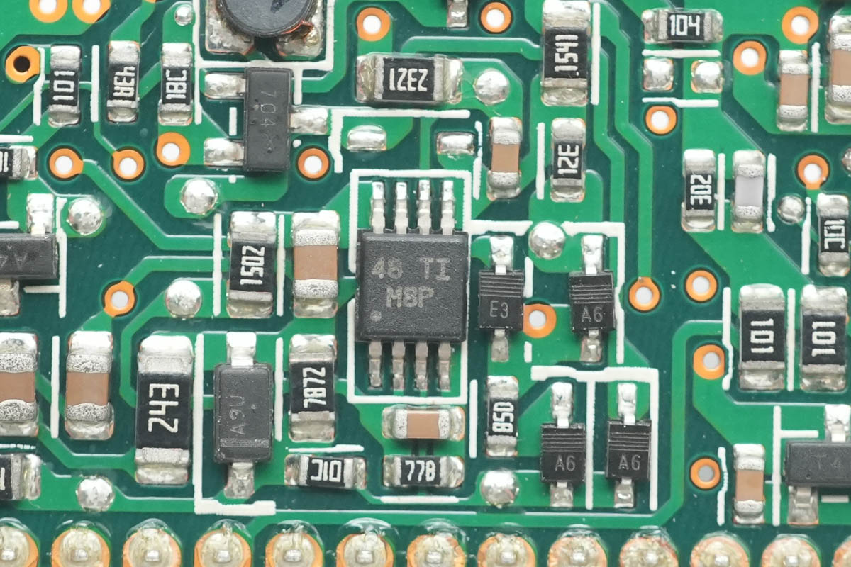
The voltage comparator is from TI, marked M8P, model LM393A. It is an industrial-grade, dual-channel precision differential comparator and comes in a VSSOP-8 package.

The output control MOSFETs are from Nexperia, marked 1R225, model PSMN1R2-25YL. They are NMOS with a voltage rating of 25 V, on-resistance of 1.2 mΩ, and come in an LFPAK2 package.
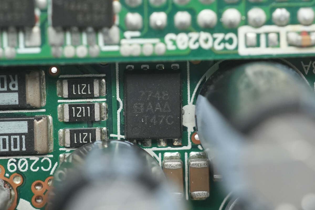
Another output control MOSFET is from VISHAY, model Si7748DP. It is an NMOS with a voltage rating of 30 V, an on-resistance of 3.9 mΩ, and comes in a PowerPAK SO-8 package.
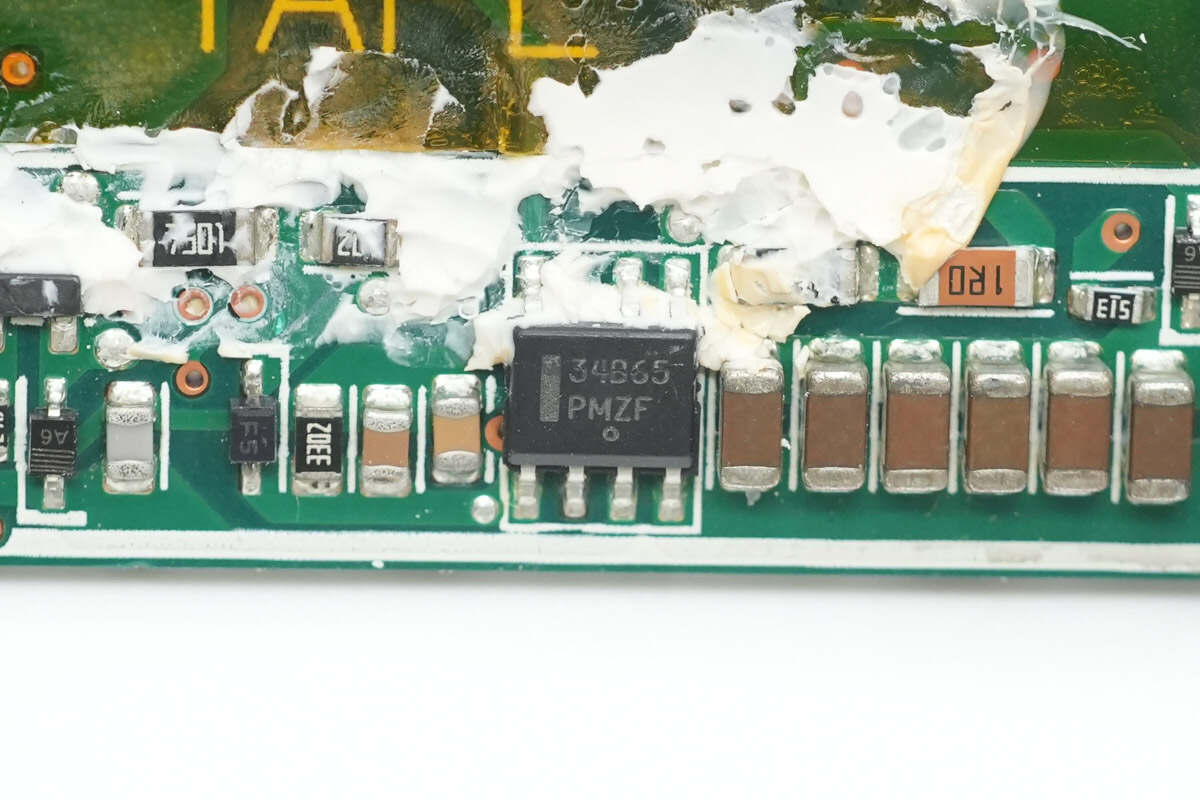
The standby power chip is from Onsemi, marked 34B65, model NCP1234BD65. It is a current-mode flyback controller with a fixed switching frequency of 65 kHz and comes in an SOIC-7 package.
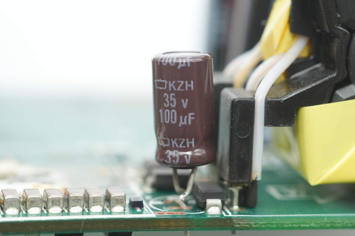
The power supply filter capacitor is from NCC, rated at 35 V, 100 μF.

The standby power MOSFET is from Infineon, model SPD06N80C3. It is an NMOS with a voltage rating of 800 V, an on-resistance of 900 mΩ, and comes in a TO-252-3 package.

Close-up of the standby power transformer.

The Everlight EL357N optocoupler is used for output voltage feedback.

The synchronous rectifier controller is from DIODES, model ZXGD3103N8. It is suitable for flyback and LLC applications, supports DCM, CrCM, and CCM operating modes, operates with a supply voltage range of 5–15 V, supports switching frequencies up to 250 kHz, and comes in an SO-8 package.

The synchronous rectifiers are from RENESAS, model RJK1056DPB. They are NMOS with a voltage rating of 100 V, on-resistance of 11 mΩ, and come in an LFPAK package.
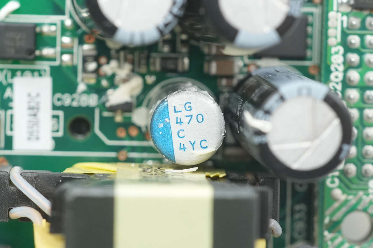
The filtering capacitor is from Nichicon, part of the PLG series of conductive polymer aluminum solid electrolytic capacitors, with a rating of 470 μF, 16 V.
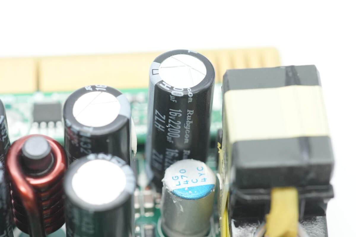
Another filtering capacitor has a rating of 2200 μF, 16 V.

The output-side filtering capacitor is rated at 220 μF, 35 V.
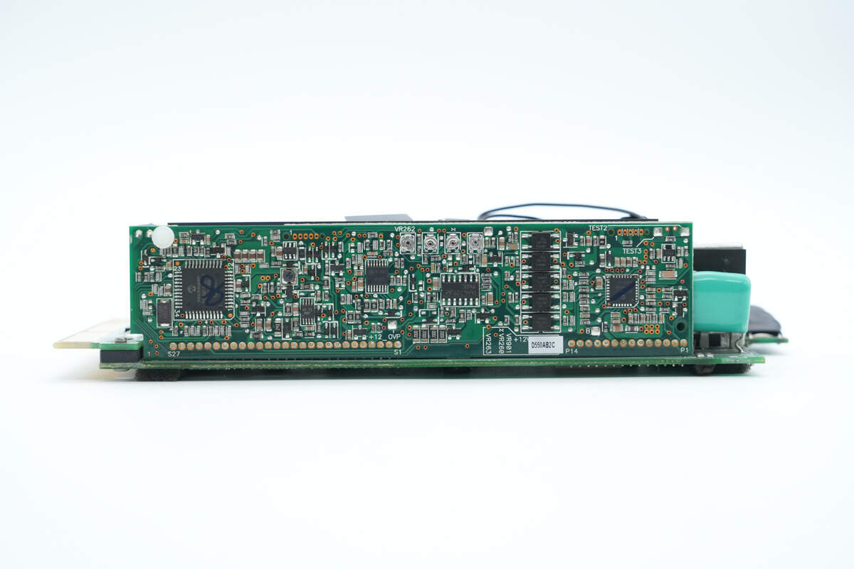
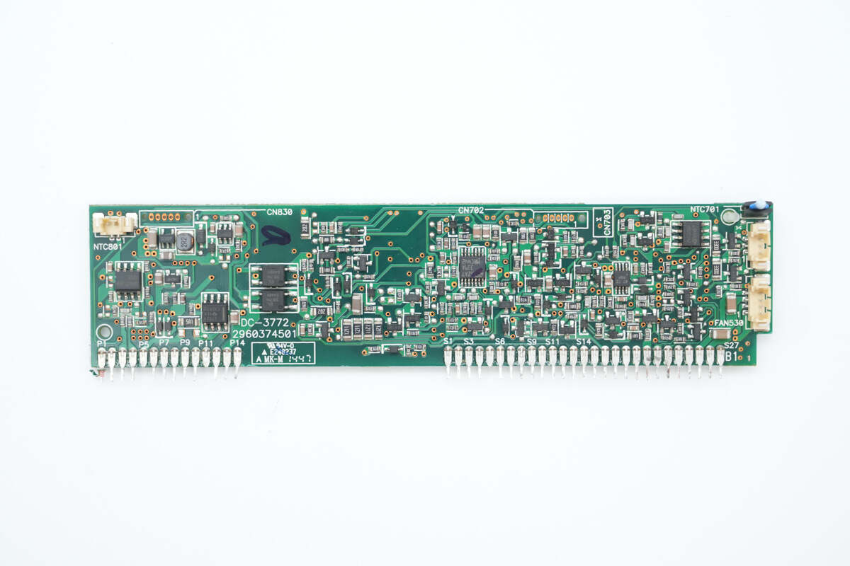
The control PCB is soldered on this side of the PCBA module.

Remove the control PCB. The outer side is equipped with an MCU, voltage comparator, operational amplifier, isolation optocoupler, and PFC controller.
The other side features an operational amplifier, driver, isolation optocoupler, voltage comparator, and memory.

The PFC controller is from Microchip, model dsPIC33FJ16GS502. It features a 16-bit dsPIC33F CPU with a 50 MHz main frequency, 16 KB of internal FLASH, and 2 KB of RAM. It supports high-speed PWM output for PFC boost control and comes in a QFN28 package.

The voltage comparator is from STMicroelectronics, marked K511, model TS391ILT. It is a low-power single-channel voltage comparator in a SOT23-5 package.

The operational amplifier is from STMicroelectronics, model LM358A. It is a low-power dual op-amp in an SO8 package.

The synchronous rectifier driver is from Texas Instruments, model UCC27524. It is a dual-channel, 5 V, high-speed low-side gate driver with negative input voltage capability, housed in an SOIC-8 package.

Two EL357N optocouplers are used for isolation communication.

The back side is also equipped with five additional optocouplers of the same model.

Another MCU is also from Microchip, model PIC18F46K20. It features a high-performance RISC core CPU, 64 KB of internal FLASH, 3,936 bytes of RAM, and 1 KB of EEPROM. It includes built-in ADC and DAC and comes in a TQFP44 package.

Close-up of the external 16.000 MHz clock crystal.

The memory is from STMicroelectronics, model M24C02, with a capacity of 256 bytes. It supports a 2.5–5.5 V operating voltage and comes in an SO8N package.
The voltage comparator is from TI, model LM393A.

The quad operational amplifier is from Onsemi, model LM324A, housed in a TSSOP-14 package.

Another operational amplifier is from STMicroelectronics, model LM324A, in an SO-14 package.

Close-up of the four potentiometers.

The voltage comparator is from TI, model LM393A.

The voltage comparator is from STMicroelectronics, model LM339A. It is a low-power, quad-channel voltage comparator in a TSSOP-14 package.
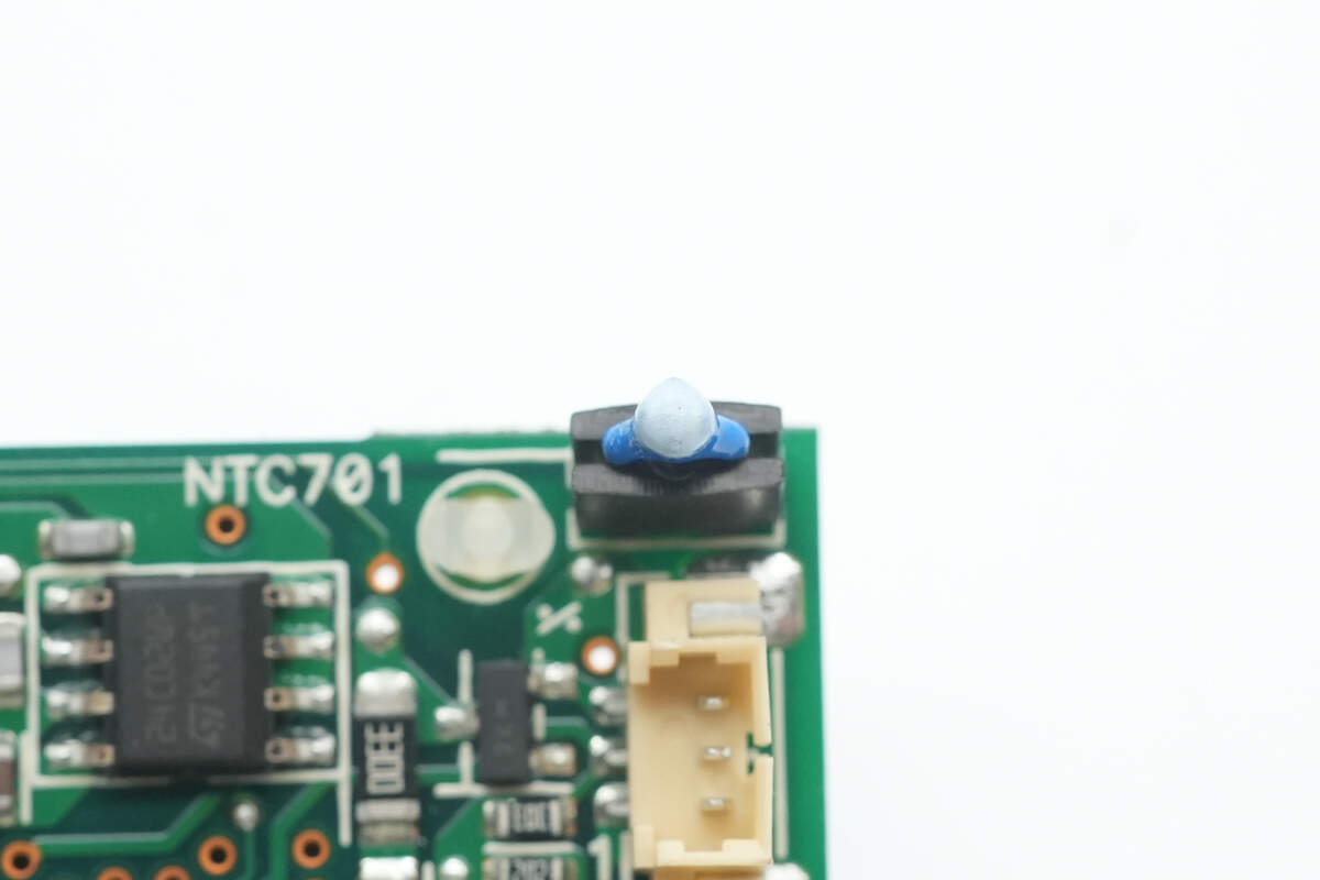
The NTC thermistor is used to monitor the power supply intake temperature.
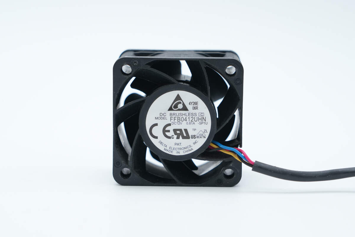
The cooling fan is from Delta, model FFB0412UHN, rated at 12 V, 0.81 A.

Well, those are all components of the Delta 550W SiC Server Power Supply.
Summary of ChargerLAB

Here is the component list of the Delta 550W SiC Server Power Supply for your convenience.
It features a hot-swappable design and supports a wide input voltage range of 100–240 V. The rated output voltage is 12 V with an output current of 45 A, while the standby output provides 12 V at 3 A. A cooling fan is installed on the input side, drawing air from the output side and expelling it through the input side. The input side also includes an AC input socket, an indicator light, and a handle, while the output side is equipped with a gold-finger connector.
After taking it apart, we found that it uses a PFC + LLC + synchronous rectification architecture. The PFC controller is from Microchip, model dsPIC33FJ16GS502, paired with a TI UCC27524 to drive the PFC MOSFET. The PFC MOSFET is an Infineon IPW60R125CP, and the PFC rectifier uses a Wolfspeed C3D06060A SiC diode.
The LLC controller is a SanKen SSC9522S, paired with Infineon IPA60R165CP MOSFETs, while the synchronous rectifiers use BSC036NE7NS3G. The standby power supply is controlled by an Onsemi NCP1234BD65, and its synchronous rectifier controller is a DIODES ZXGD3103N8. The PCBA module consists of multiple small PCBs soldered together, with Mylar sheets used for insulation between them. Japanese electrolytic capacitors are used for filtering, and the material selection and workmanship are solid and reliable.
Related Articles:
1. Teardown of ASUS Adol 100W GaN Quick Charger (ADOL AC100-050A)
2. Teardown of CUKTECH 15 Charging Station (TA1406U)
3. Teardown of Xiaomi 45W GaN Pudding Charger (MDY-18-EZ)