Introduction
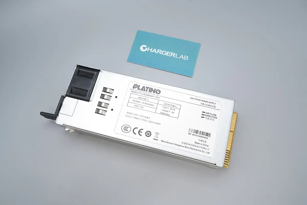
This time, we are going to teardown the Boco Electronics 800W SiC Server Power Supply, model BCSE800AP-12E01. It supports AC input voltage from 100 to 240V and DC input voltage of 240V. The power supply’s rated output voltage is 12V with an output current of 66.7A. The standby power output is 12V with a current of 3A.
The unit features a long rectangular metal enclosure with a cooling fan, handle, indicator light, and power socket located at the input side. The output side is equipped with a gold-finger connector. The power supply adopts a PFC + LLC high-efficiency resonant topology and incorporates built-in silicon carbide diodes. Below is the teardown to explore its internal design and component quality.
Product Appearance
The front of the metal enclosure is affixed with a label.
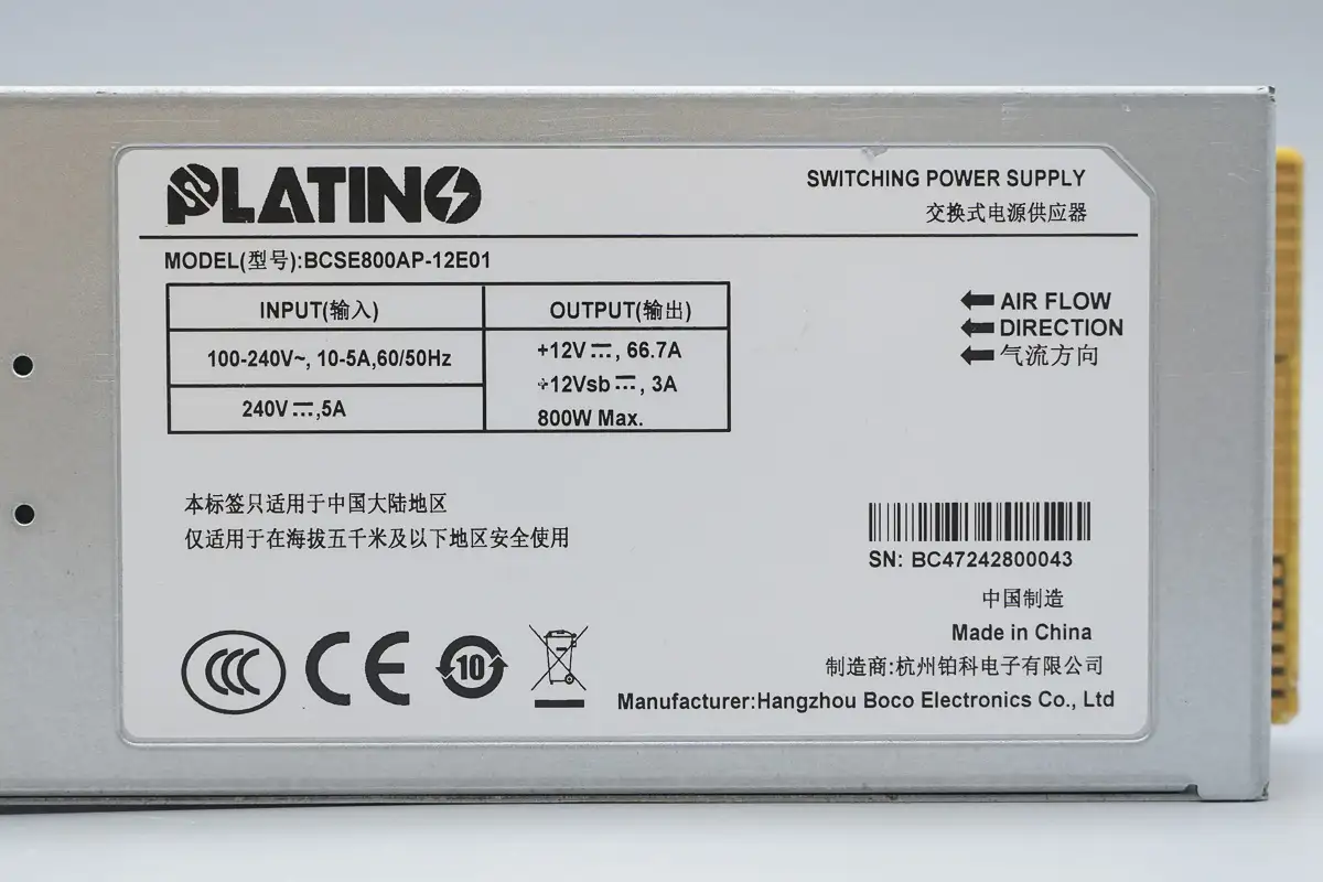
Model: BCSE800AP-12E01
Input: 100-240V~, 10-5A, 60/50Hz
240V, 5A
Output: +12V, 66.7A
+12Vsb, 3A
800W Max
Made in China
Manufacturer: Hangzhou BOCO Electronics Co., Ltd.
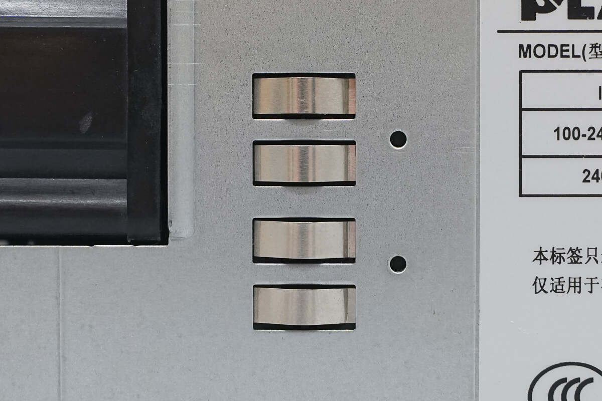
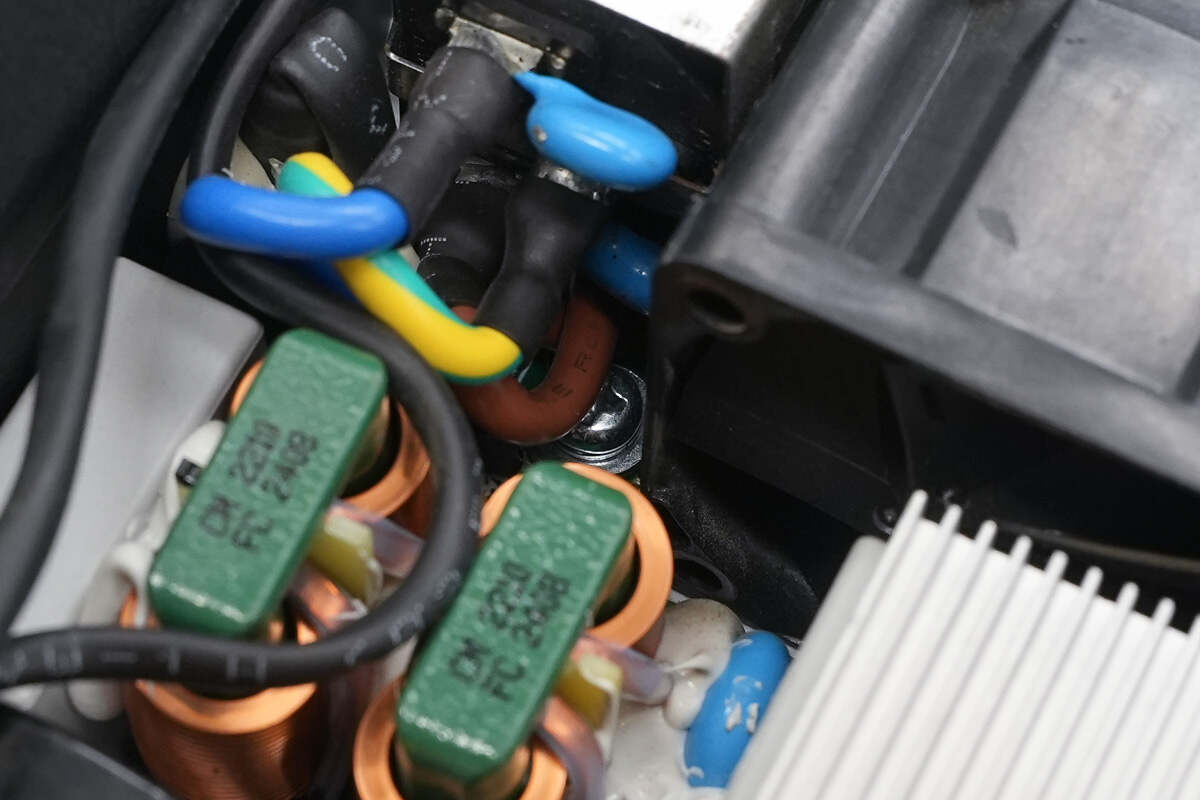
Close-up of the grounding spring clips.
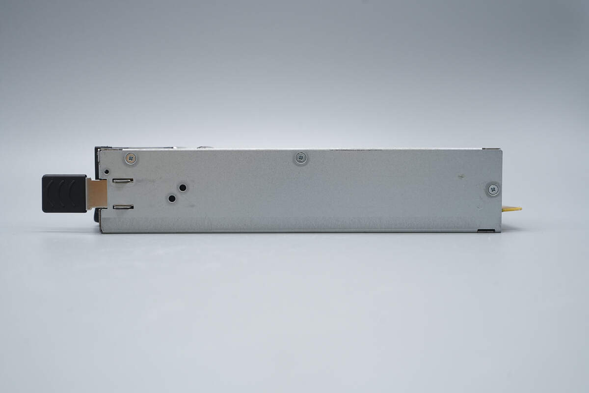
The side features mounting clips and securing screws.
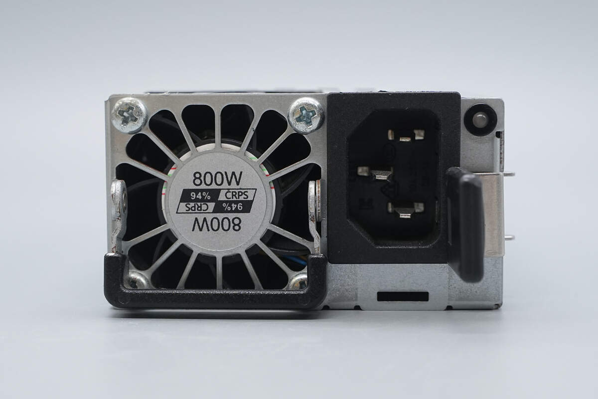
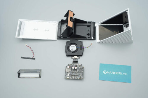
The input side is equipped with a handle, a cooling fan, an input socket, a power indicator light, and a circuit breaker handle.
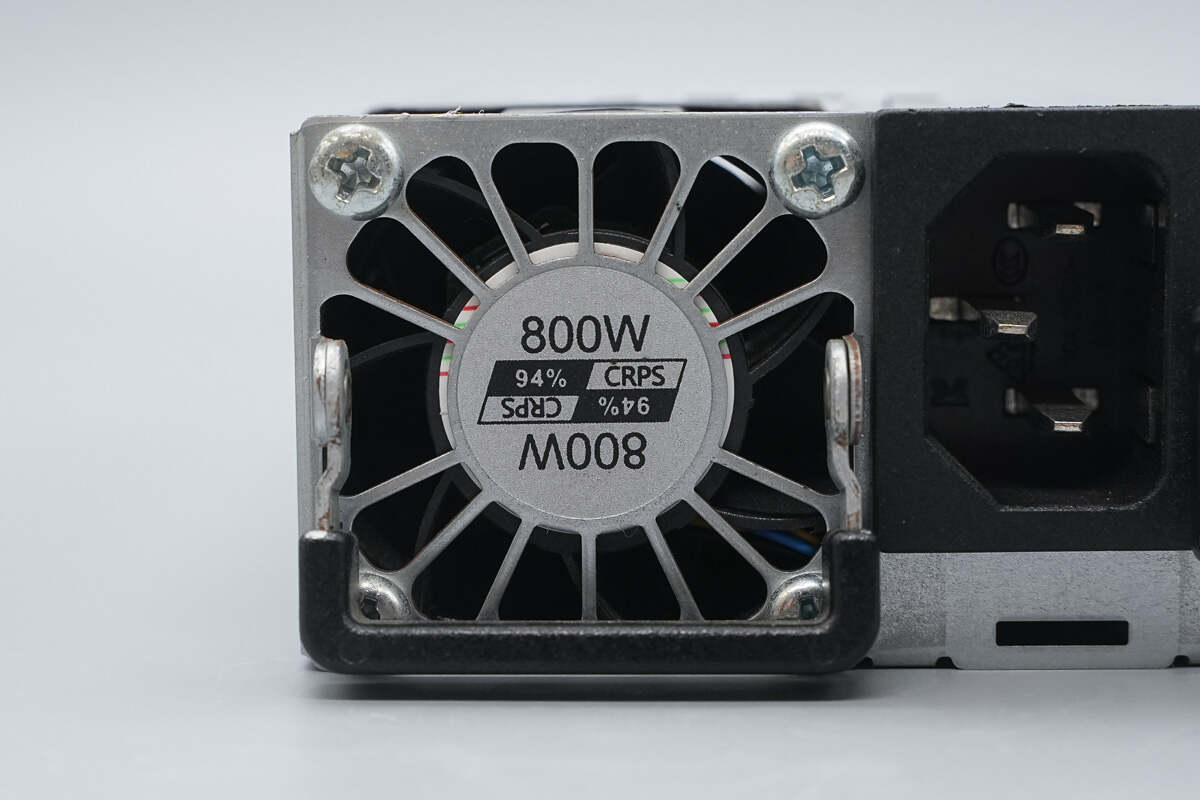
The cooling fan is equipped with a protective cover and labeled with 800W output power, 94% conversion efficiency, and a CRPS power supply.
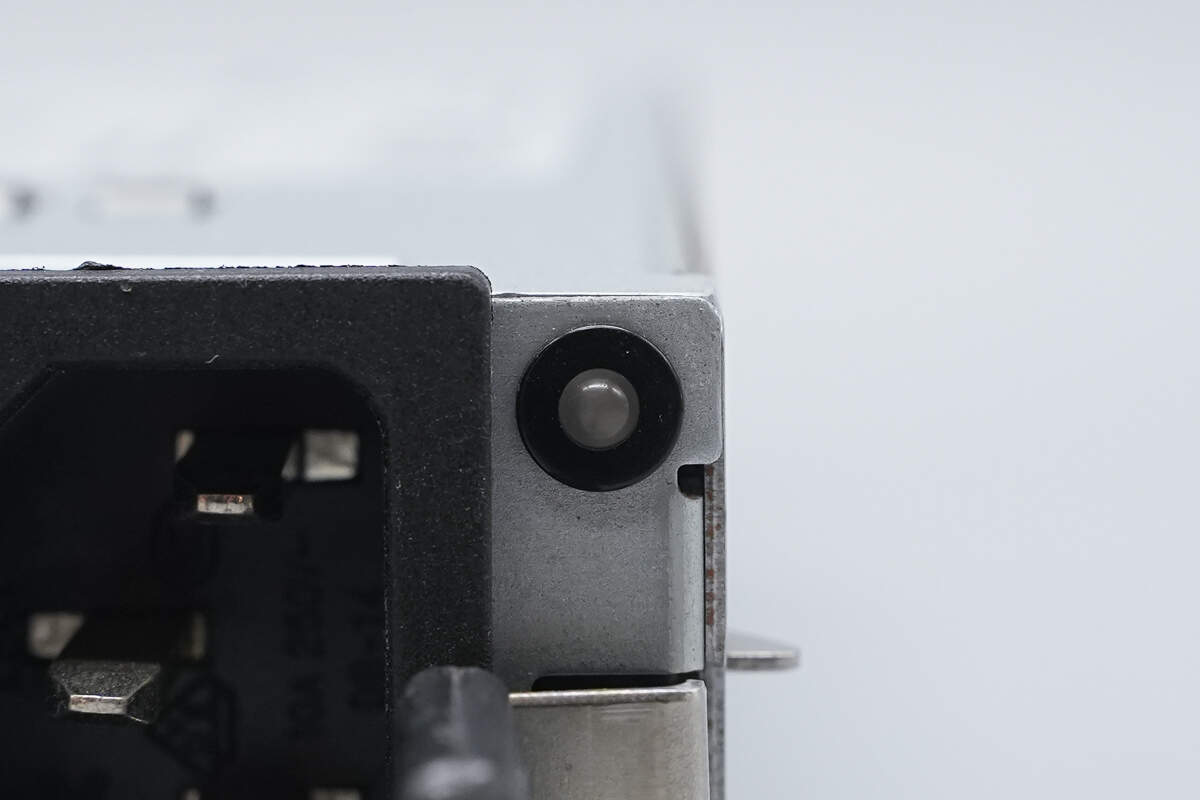
The right side is equipped with an LED indicator light.
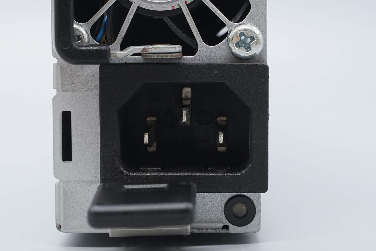
Close-up of the three-prong power socket.
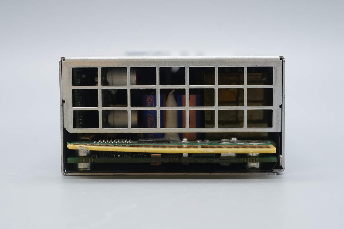
The output side is equipped with a grille and a connector.
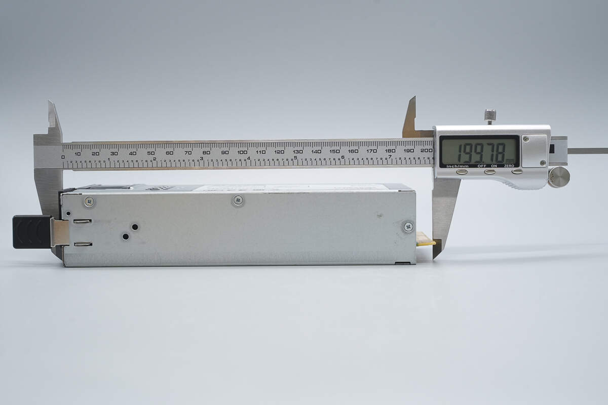
The length is about 199.8 mm (7.87 inches).
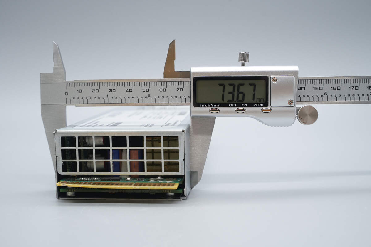
The width is about 73.7 mm (2.9 inches).
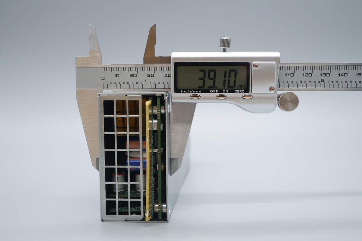
The thickness is about 39.1 mm (1.54 inches).
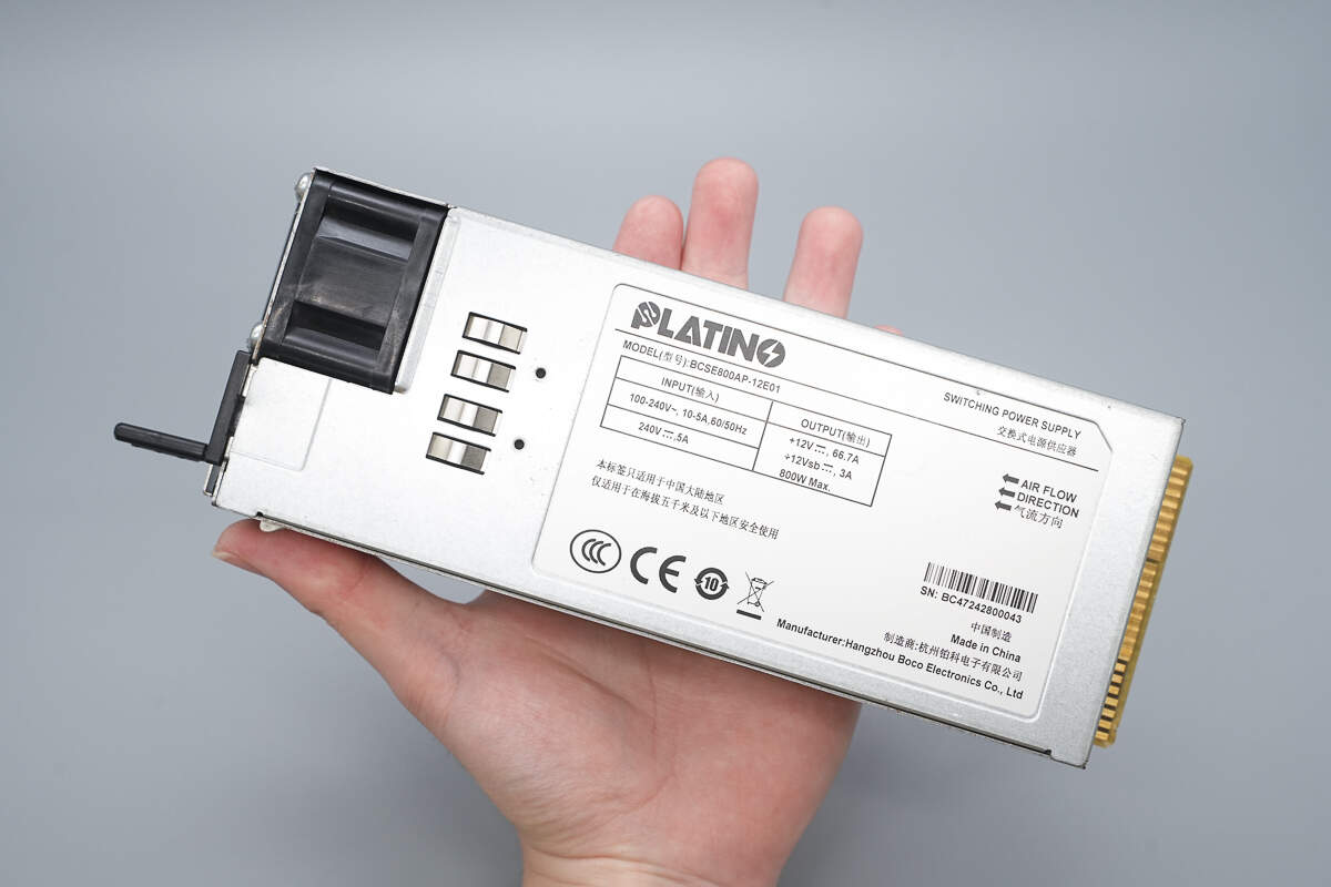
That's how big it is in the hand.
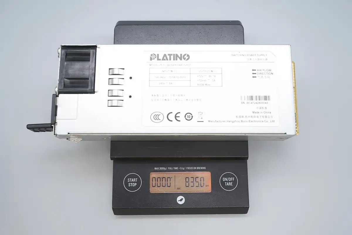
The weight is about 835 g (29.45 oz).
Teardown
Next, let's take it apart to see its internal components and structure.
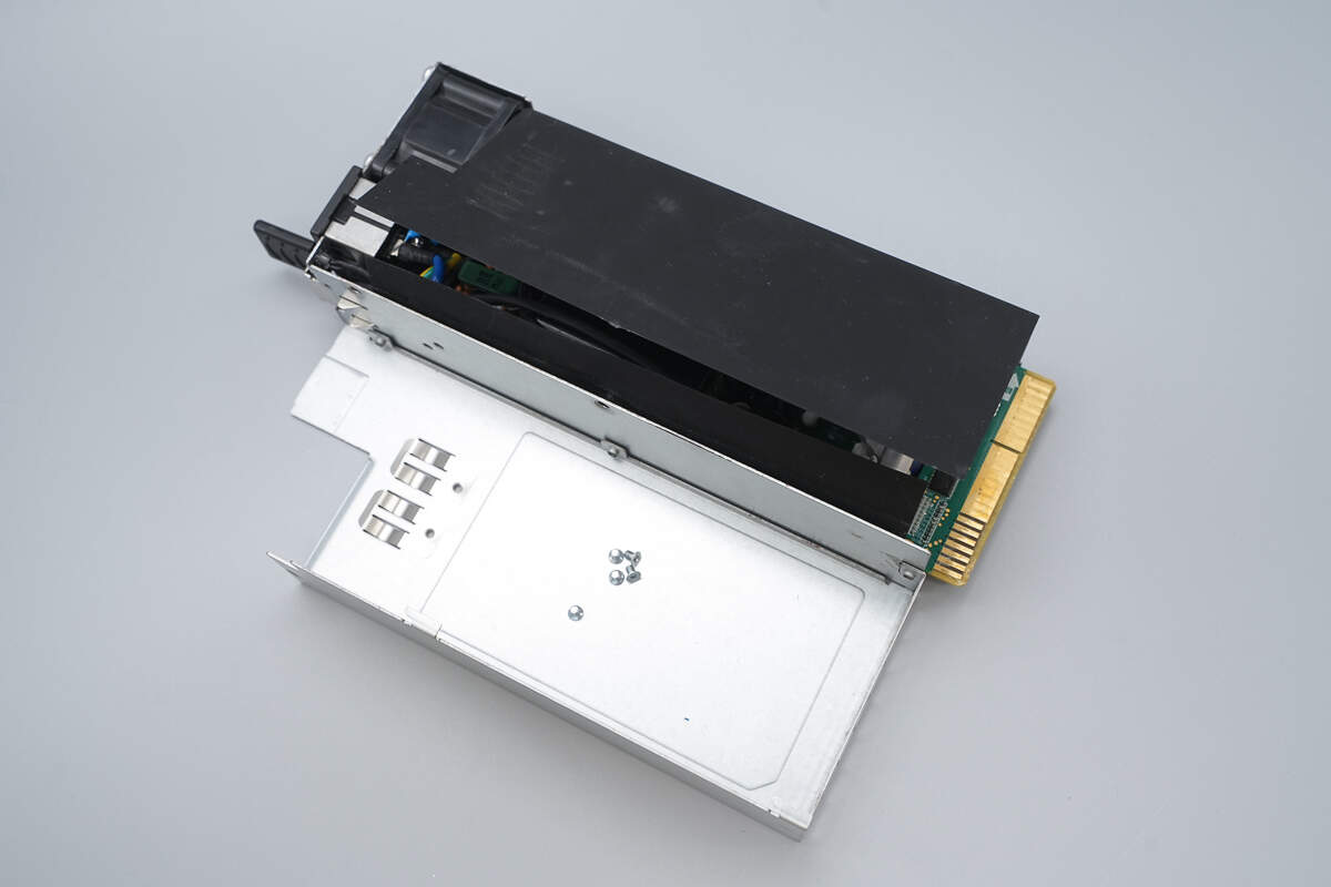
Remove the securing screws to open the enclosure.
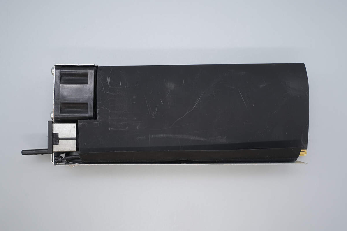
The PCBA module is insulated with a black Mylar sheet.
The PCBA module is secured inside the enclosure with screws.
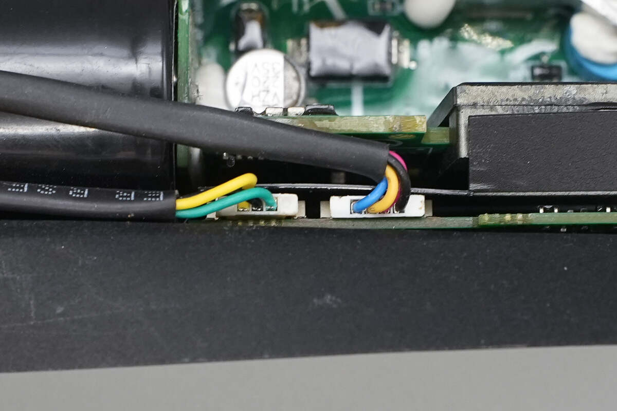
The LED indicator and cooling fan are connected via plug-in connectors.
Close-up of the screws securing the PCBA module.
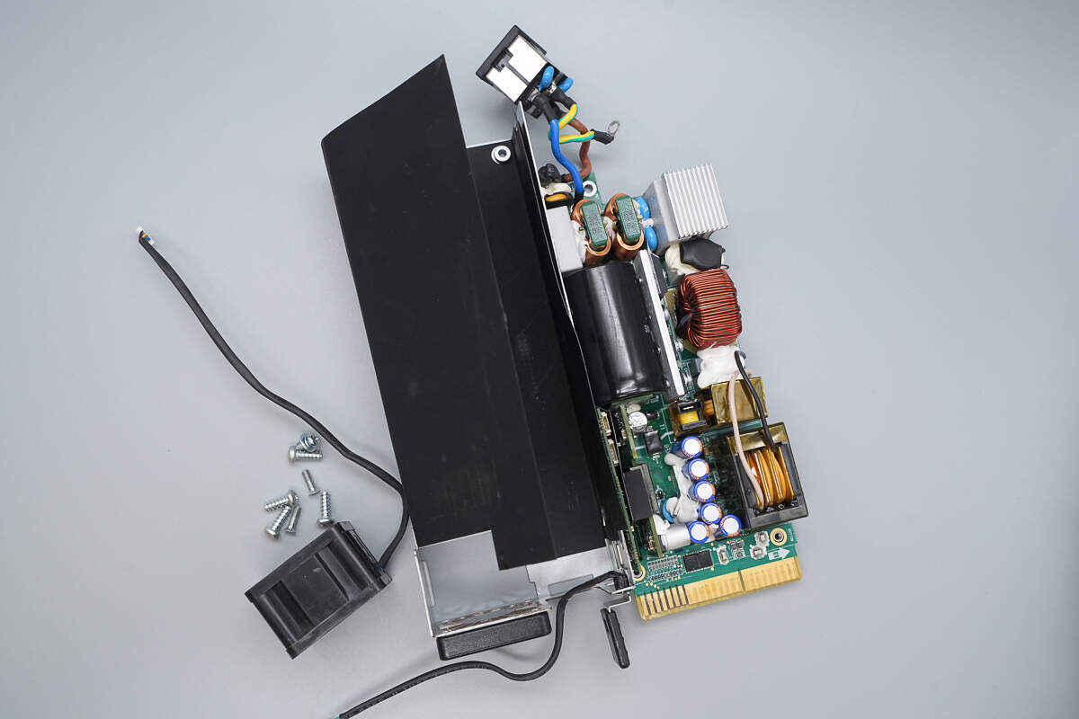
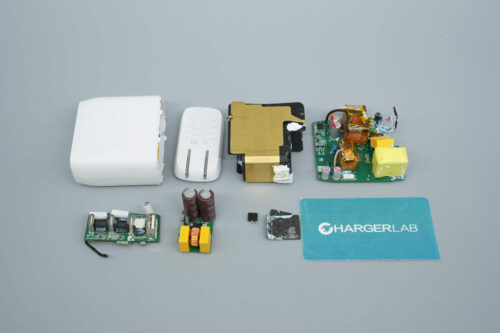
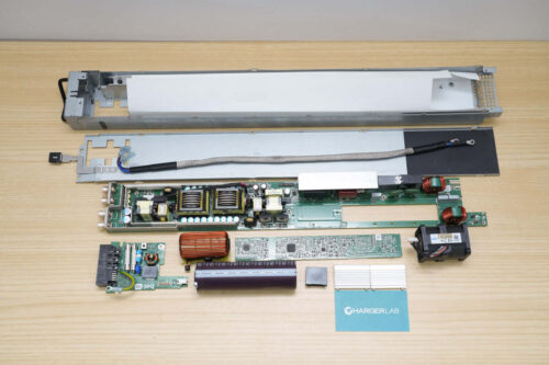
Remove the PCBA module.
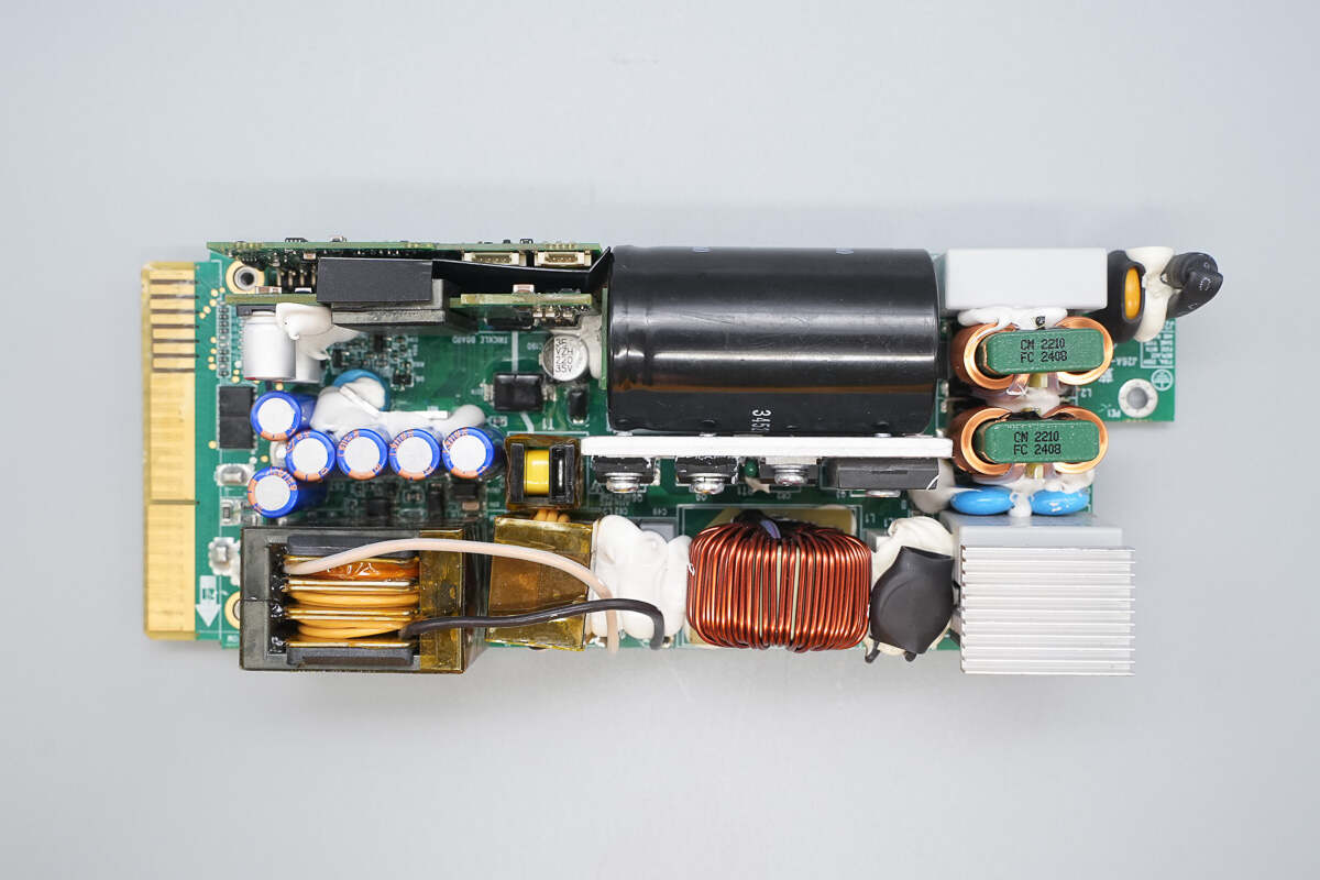
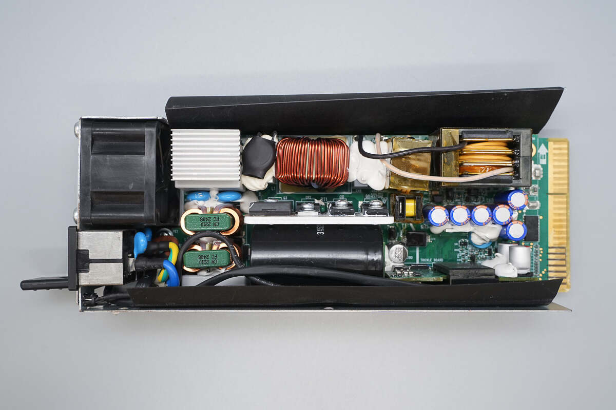
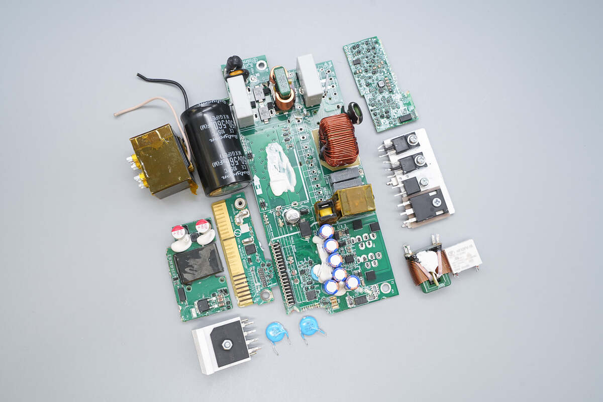
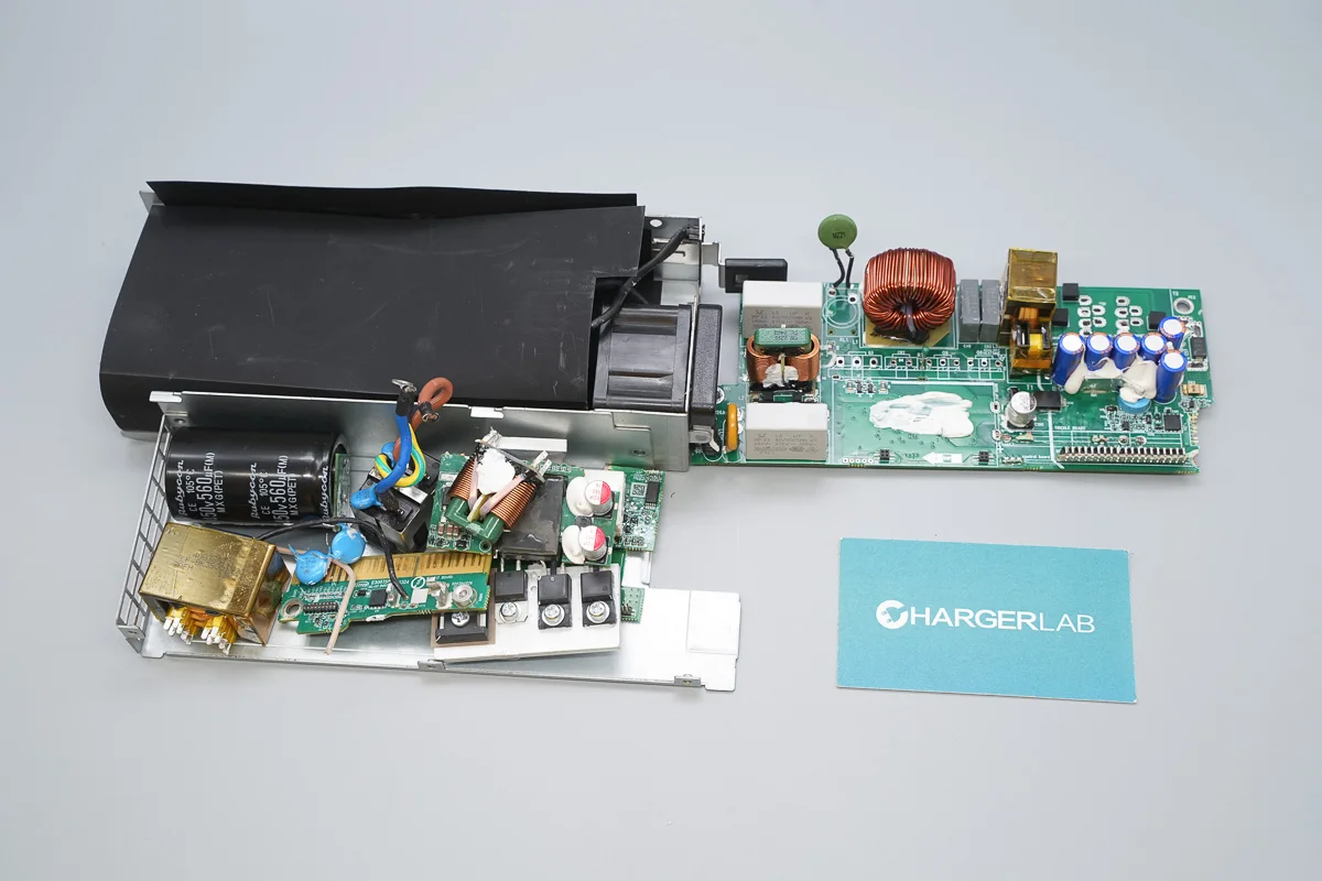
Front view of the PCBA module:
The top right corner is the input section, equipped with a fuse, varistor, safety X2 capacitors, and a common mode choke. Below these are Y capacitors and bridge rectifiers.
In the middle area, there are thermistors, a relay, a PFC boost inductor, a PFC MOSFET, a PFC rectifier, LLC MOSFETs, and a high-voltage filter capacitor.
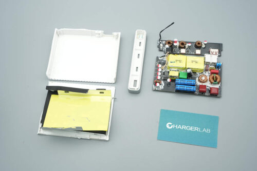
On the left side, you can find the LLC transformer, resonant inductor, current transformer, output filtering capacitors, as well as the standby power PCB and control PCB.

On the back of the module, there is a small PCB used for shielding, located opposite the PFC controller.
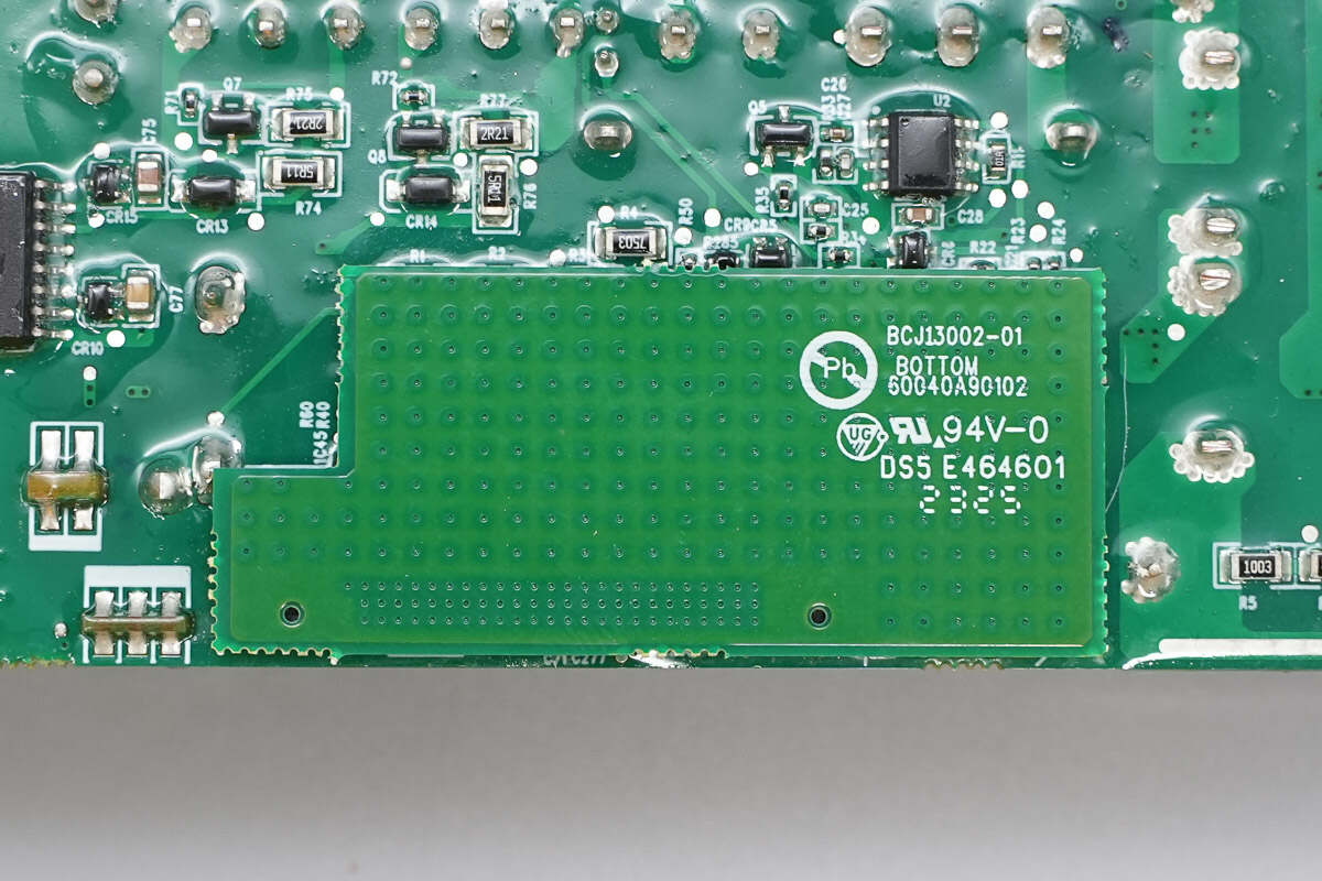
Close-up of the small shielding PCB.
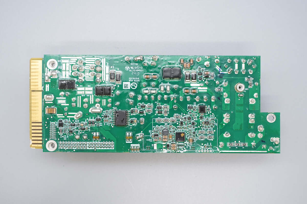
Remove the shielding PCB. Below the small PCB, there is the PFC controller, a driver, a buck converter chip, synchronous rectifiers, current-sense resistors, and an isolation driver.
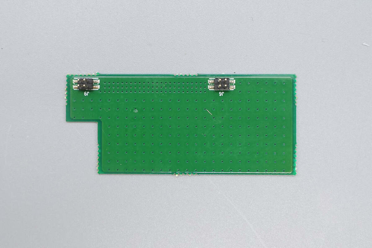
The shielding PCB is connected via pin headers.
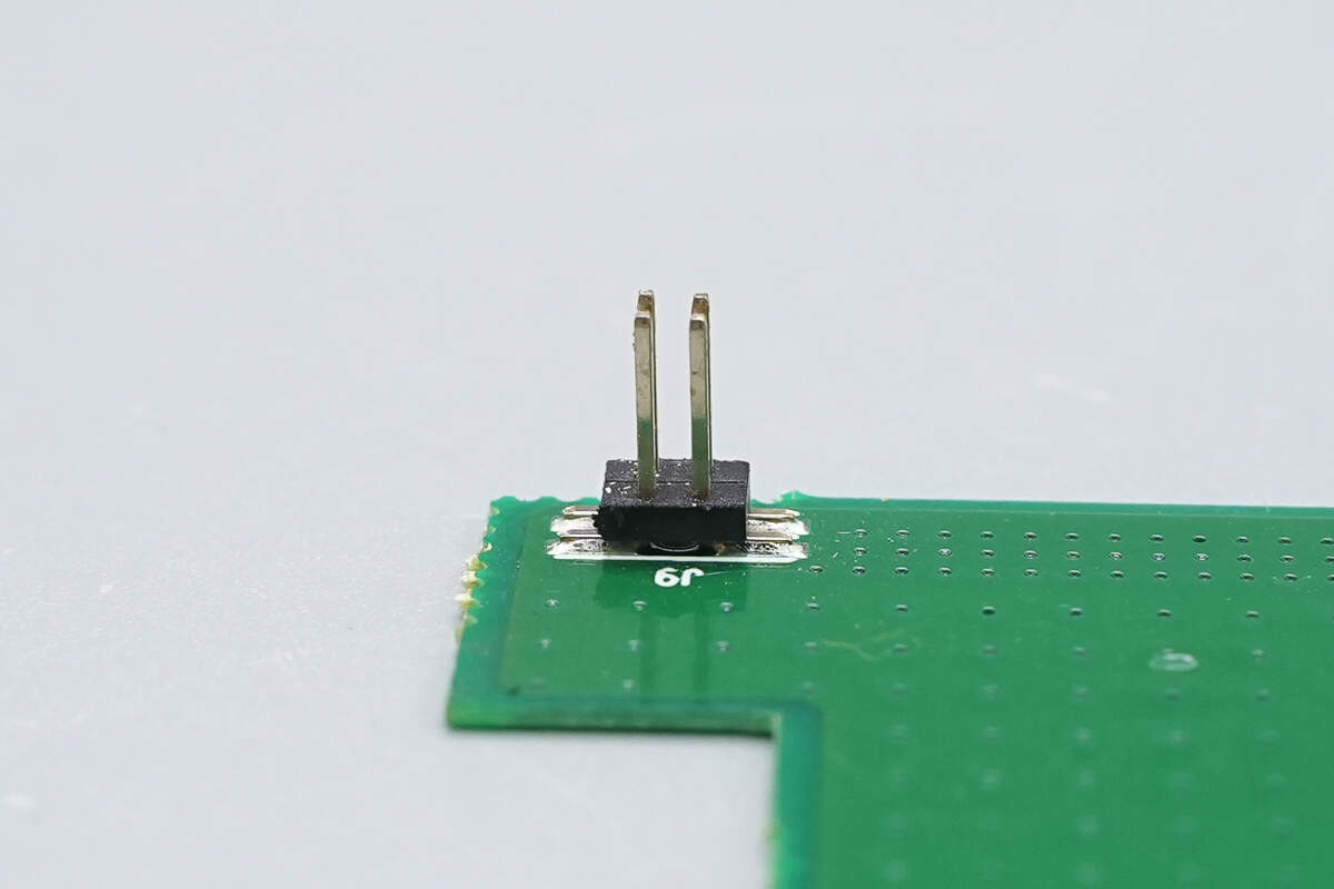
Close-up of the pin headers.
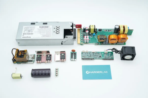
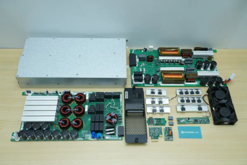
Remove the small PCBs and power components.
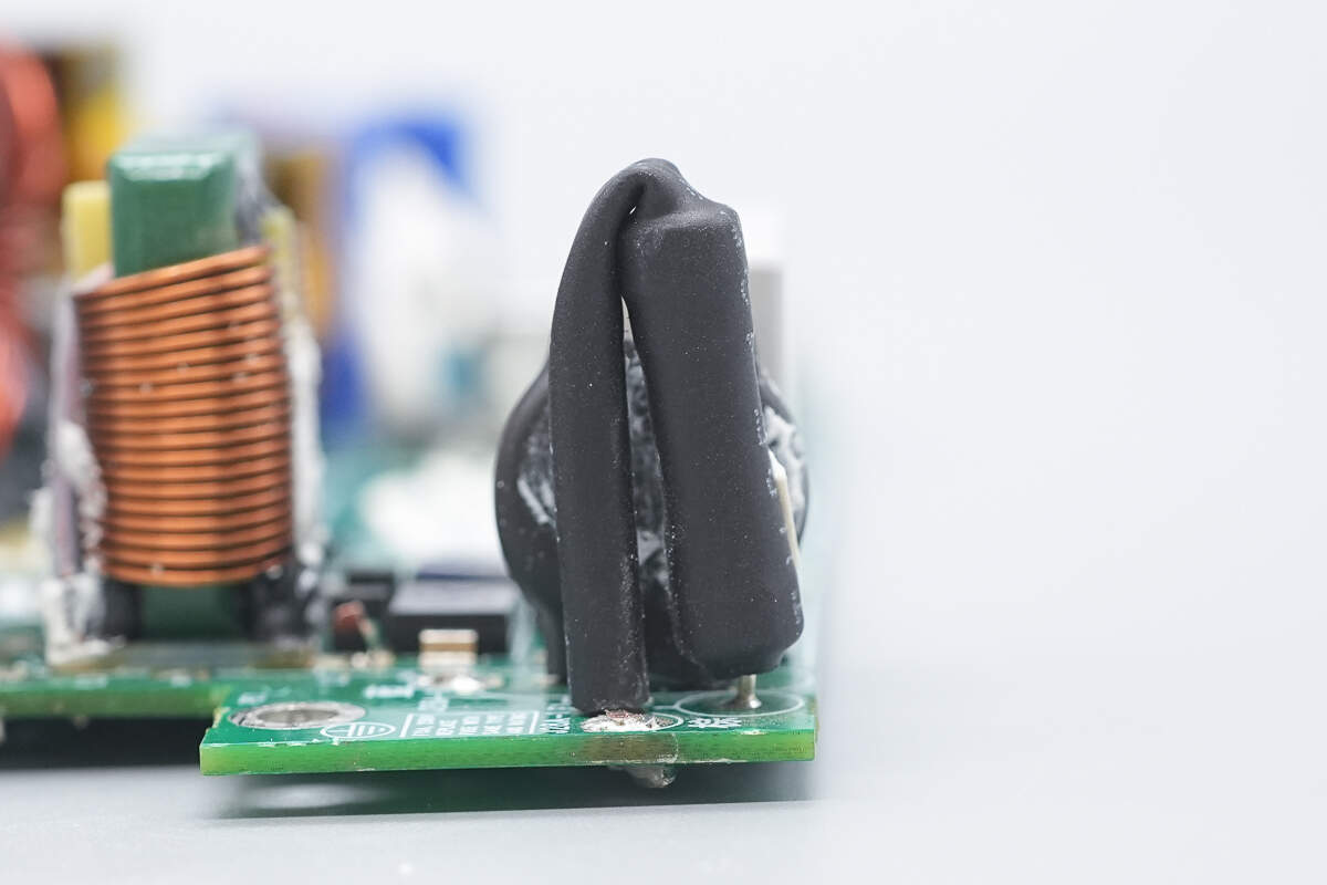
The input fuse is insulated with a heat-shrink tube.
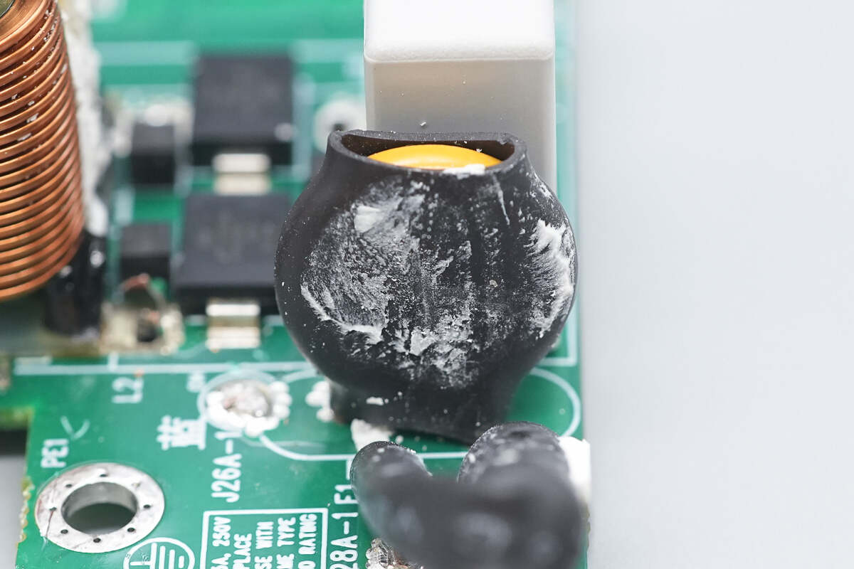
The varistor is insulated with a heat-shrink tube.
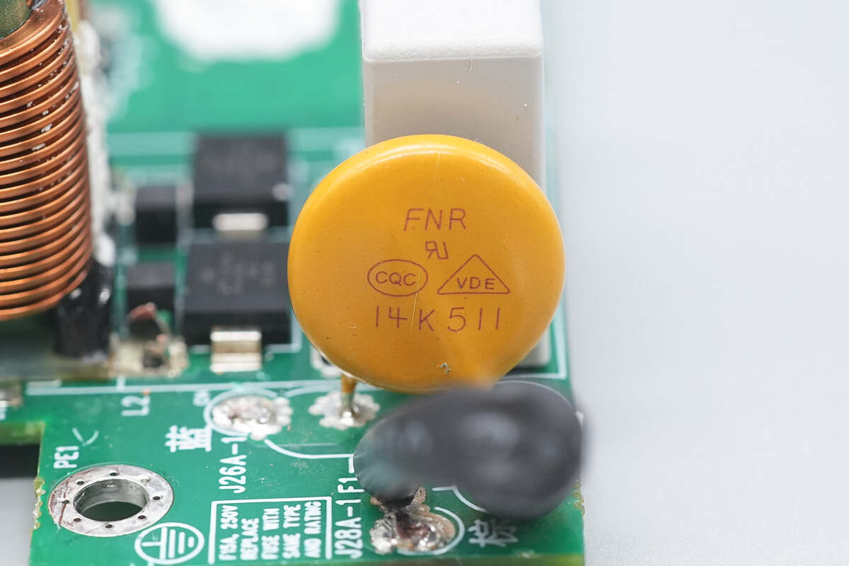
The varistor is from FNR, model FNR-14K511, used for absorbing overvoltage surges.
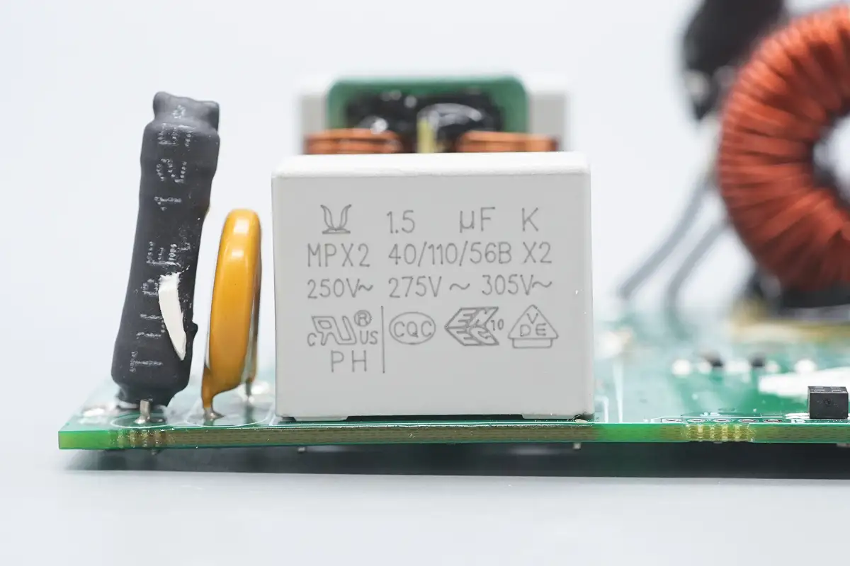
The safety X2 capacitor is from Europtronic, with a specification of 1.5μF.
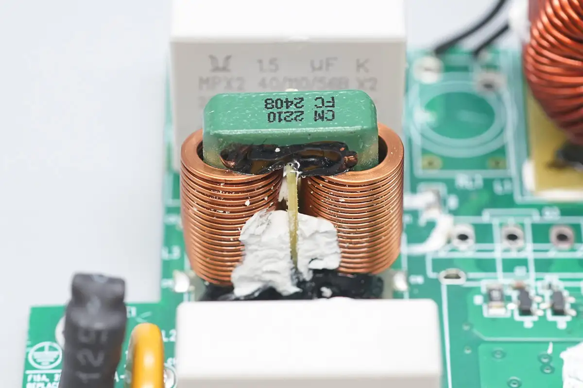
The common mode choke is wound with flat copper wire.
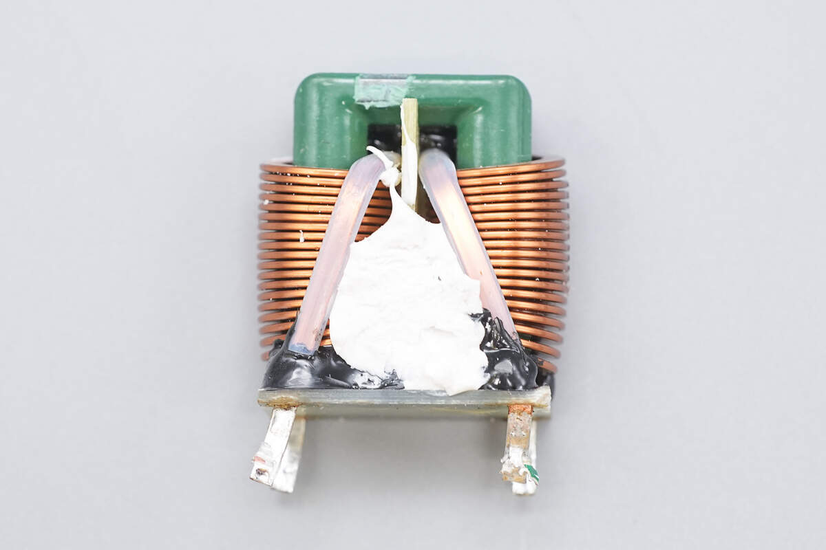
The bottom of the common mode choke is insulated with a bakelite board.
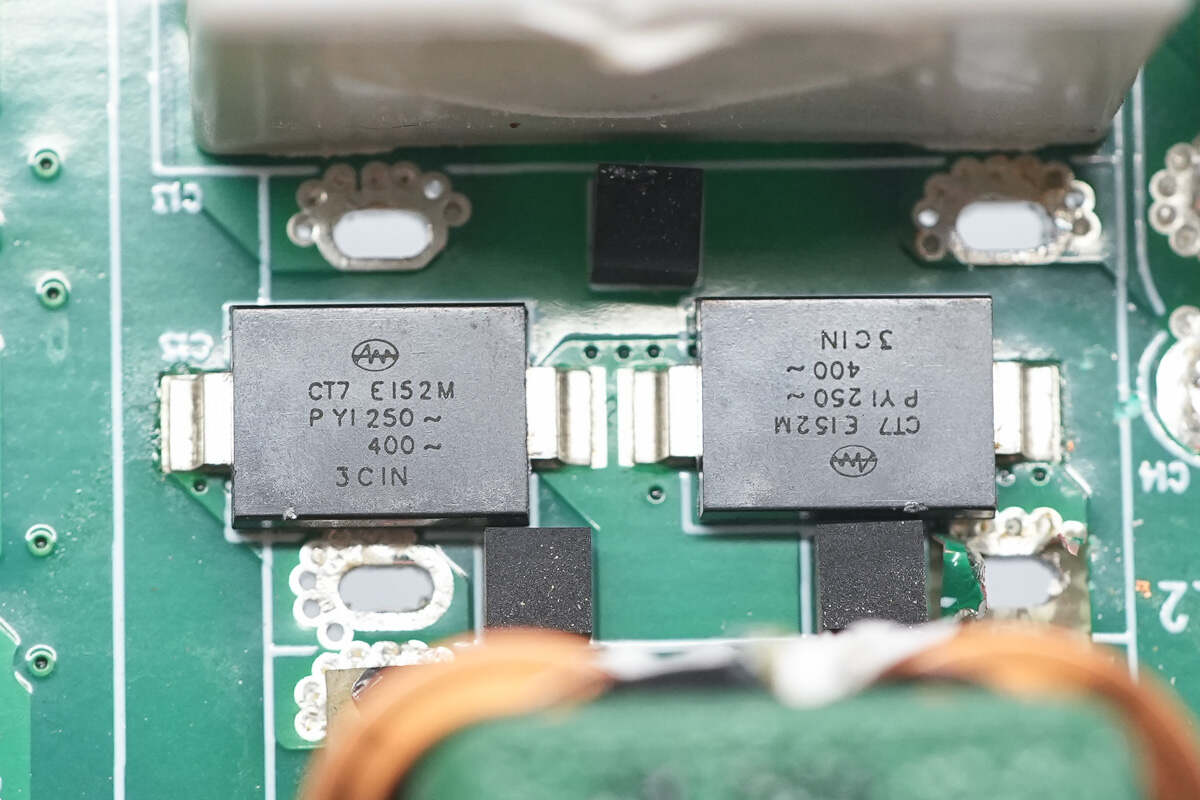
The two SMD Y capacitors are from KeiFat.
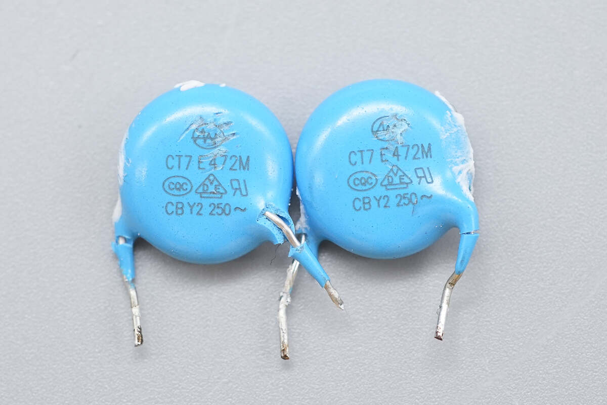
These two Y capacitors also come from KeiFat.
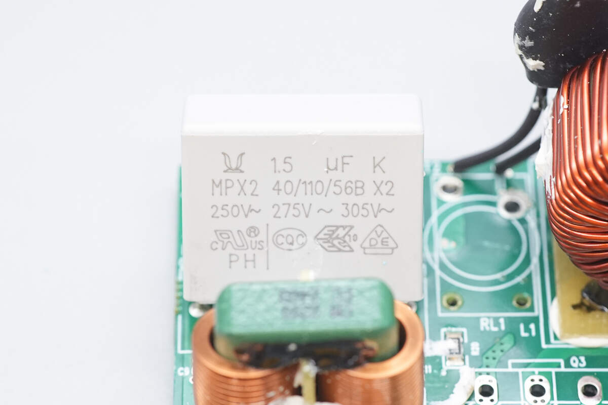
The other safety X2 capacitor has the same specifications.
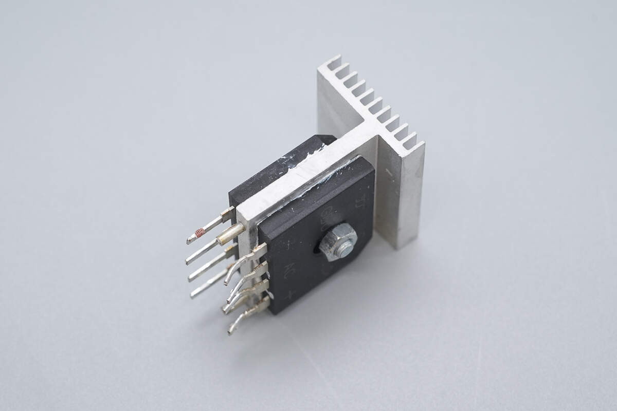
There is a bridge rectifier mounted on each side of the heatsink.
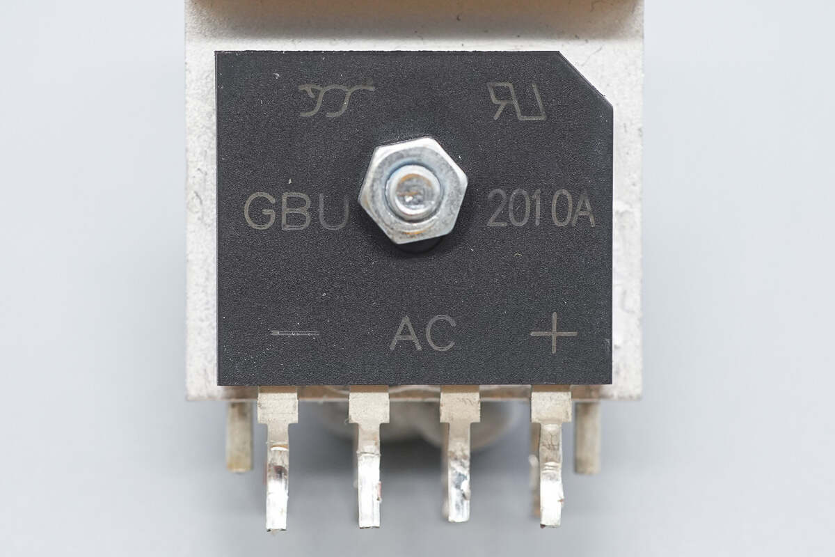
The bridge rectifiers are from YJ, model GBU2010A, rated at 1000V and 20A, using a GBU package.
The thermistor is insulated with a heat-shrink tube.
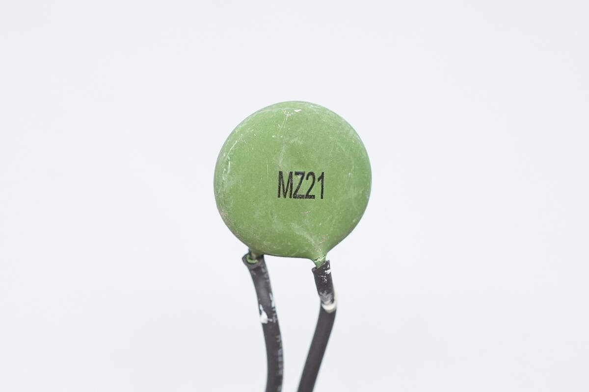
The thermistor is marked with MZ21.
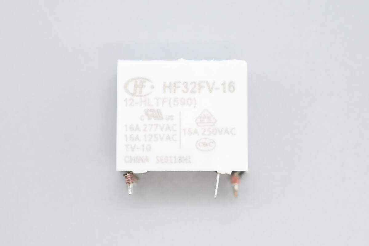
The relay is from HONGFA, model HF32FV-16/12-HLTF. It is an ultra-compact high-power relay with a contact rating of 16A at 250V and a coil voltage of 12V.
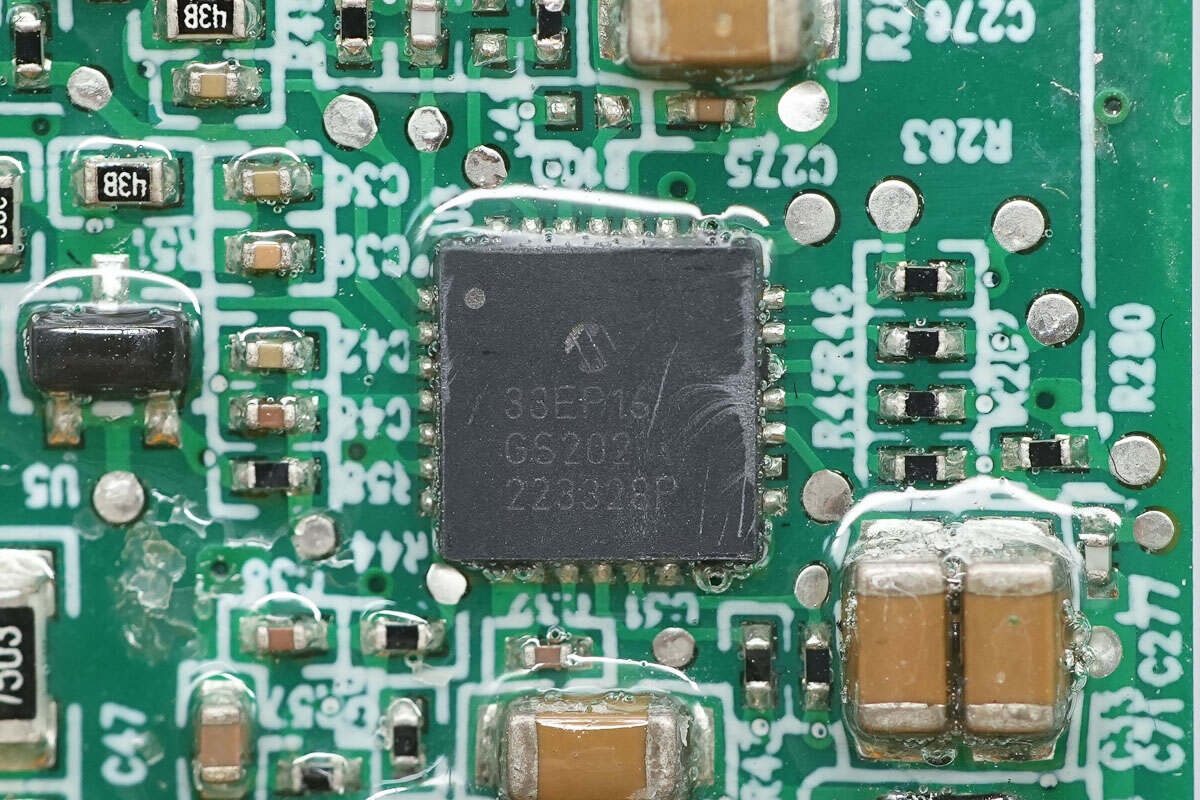
The PFC controller is from Microchip, model dsPIC33EP16GS202. It features a built-in 16-bit dsPIC33E CPU, 16KB of FLASH memory, and 2KB of SRAM. It integrates a high-speed PWM generator and a high-speed ADC, and comes in a UQFN28 package.

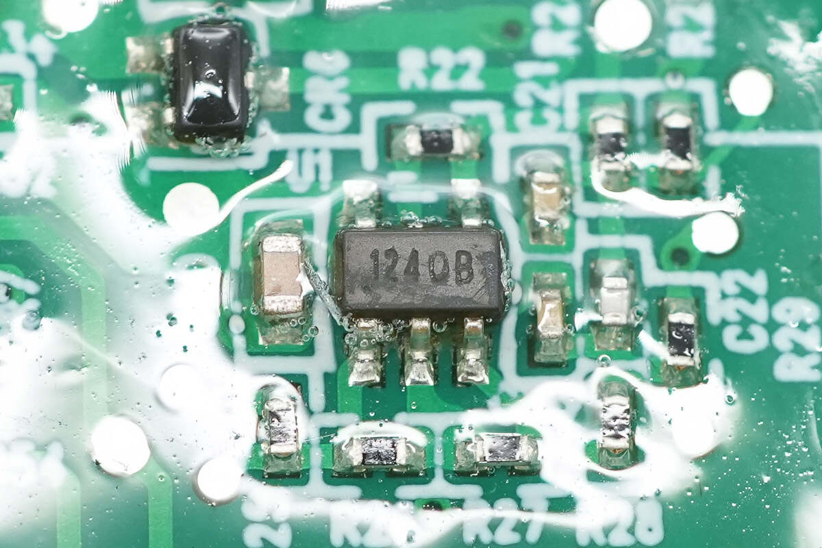
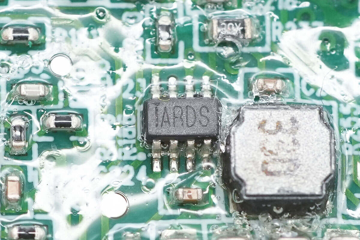
The buck converter chip is from MPS, marked with ARD, model MP2314S. It is a synchronous buck converter with an input voltage range of 4.5–24V, featuring integrated MOSFETs, supporting a 2A output current, and operating at a fixed switching frequency of 500kHz. The chip comes in a TSOT23-8 package.
The operational amplifier is from 3PEAK, model TP1241. It is a high-voltage amplifier featuring low offset, low power consumption, and stable high-frequency response. The package type is SOT23-5.
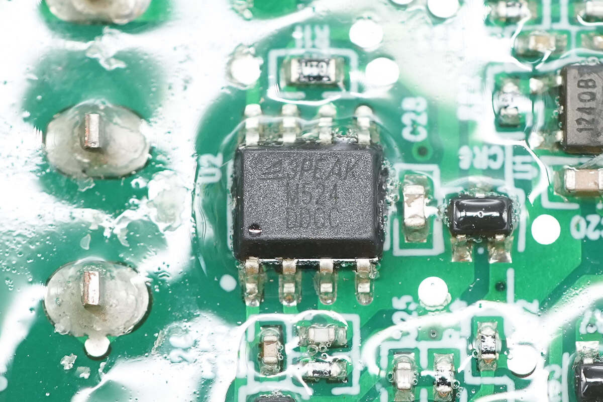
The driver is from 3PEAK, model TPM27524. It is a dual-channel high-speed low-side driver with 5A sourcing and sinking current capability. It supports MOSFET, IGBT, and GaN applications, operates at a voltage range of 4.5–25V, and comes in an SOP8 package.
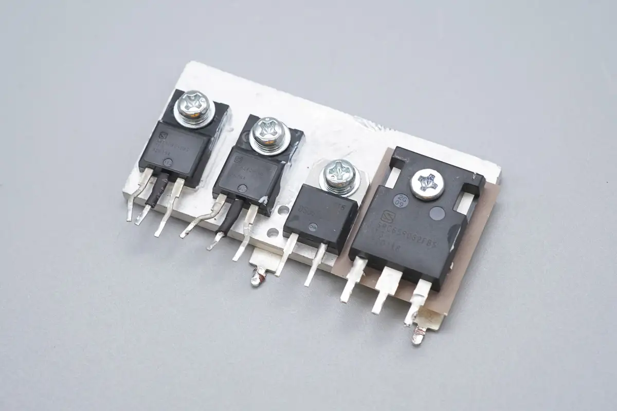
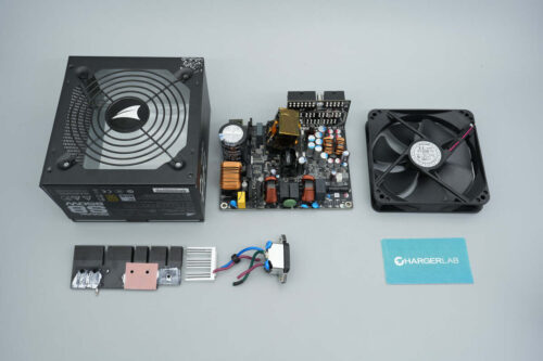
The heat sink houses LLC MOSFETs, a SiC diode, and a PFC MOSFET.
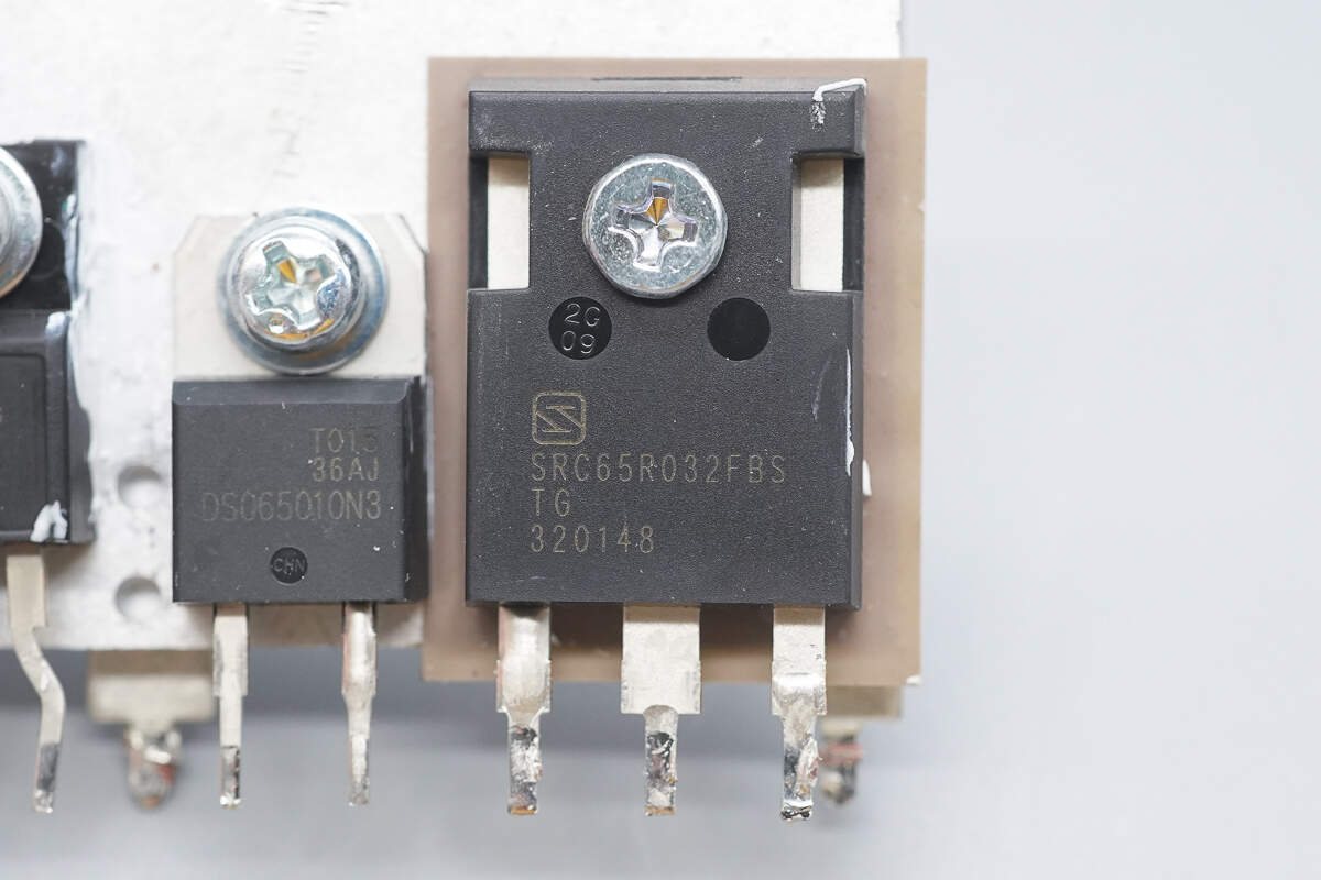
The PFC MOSFET is from Sanrise, model SRC65R032FBS. It is an NMOS transistor with a voltage rating of 650V and an on-resistance of 32mΩ, packaged in a TO-247 case.
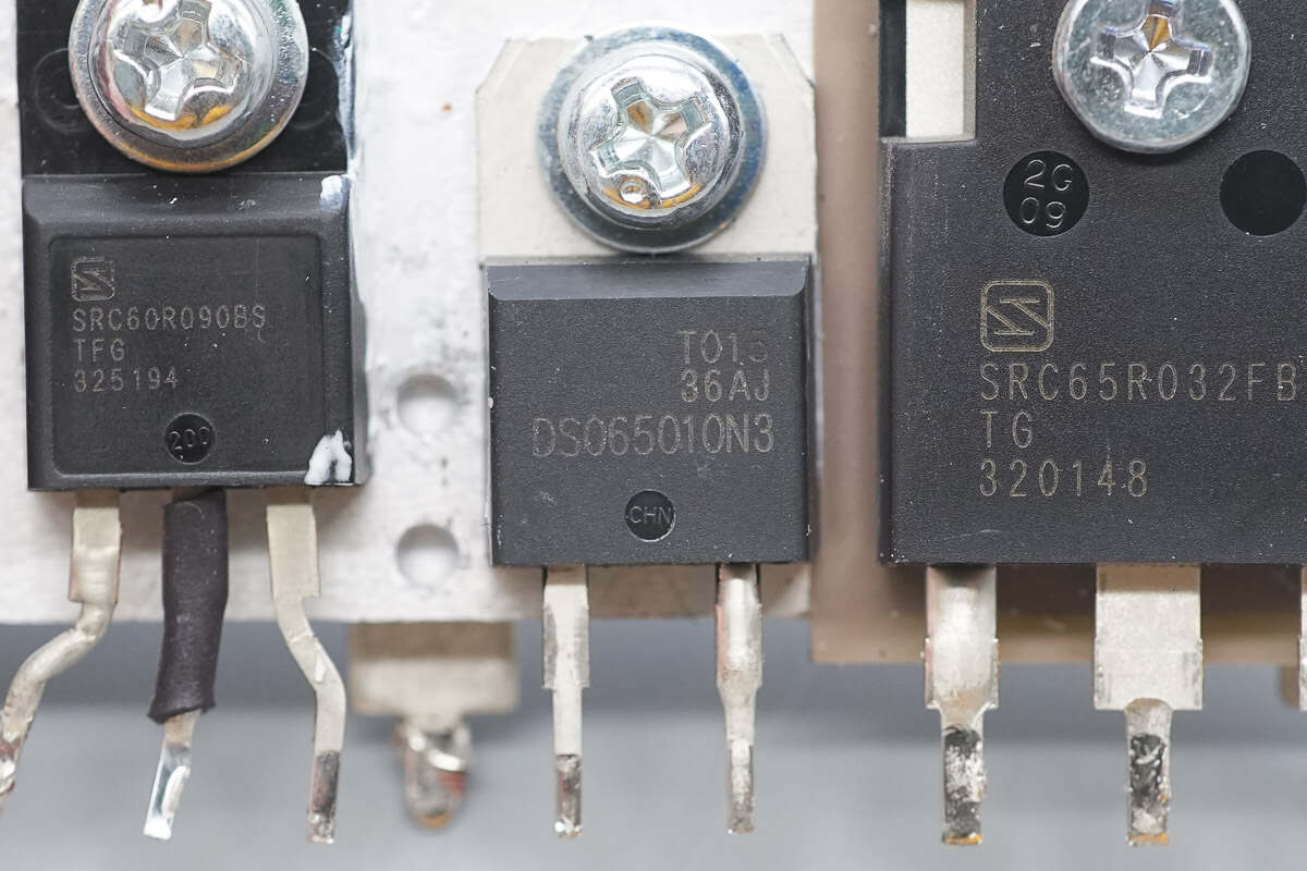
The PFC rectifier is from Sanan, marked with DS065010N3, model SDS065J010N3. It is a SiC diode rated at 650V/10A, housed in a TO-220N-2L package.

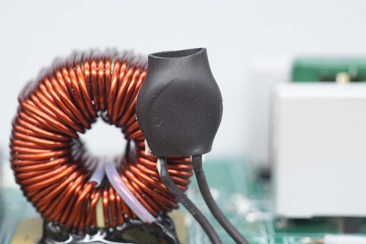
The PFC boost inductor is wound with enamel-coated wire and insulated at the bottom with a bakelite board.
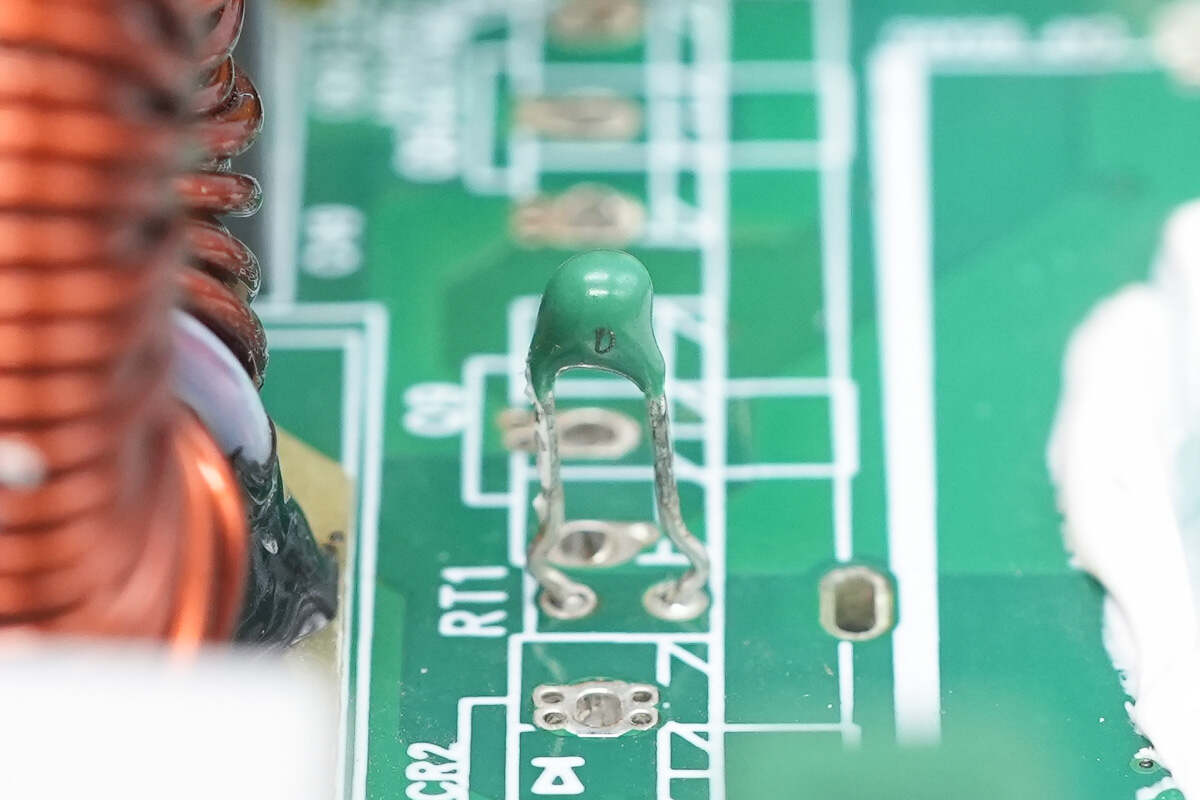
The green thermistor is used to monitor the temperature of the heatsink.
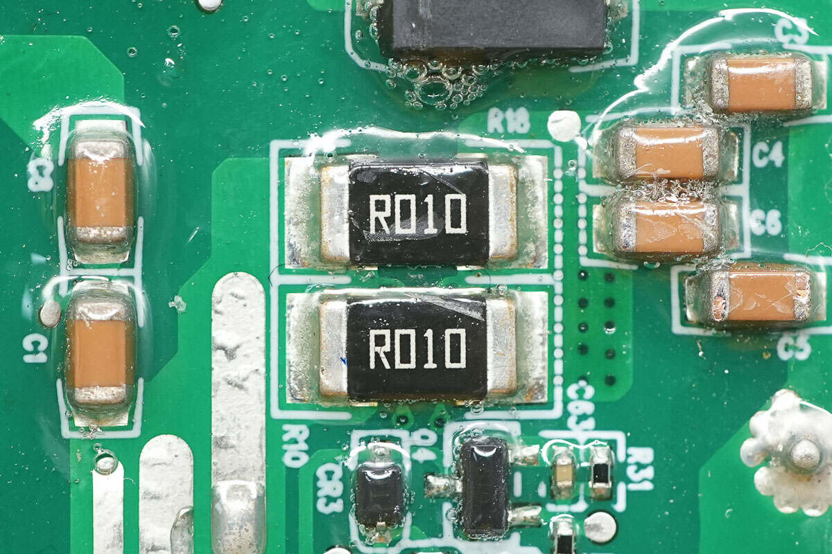
Two 10mΩ resistors are connected in parallel to sense the current of the PFC MOSFET.
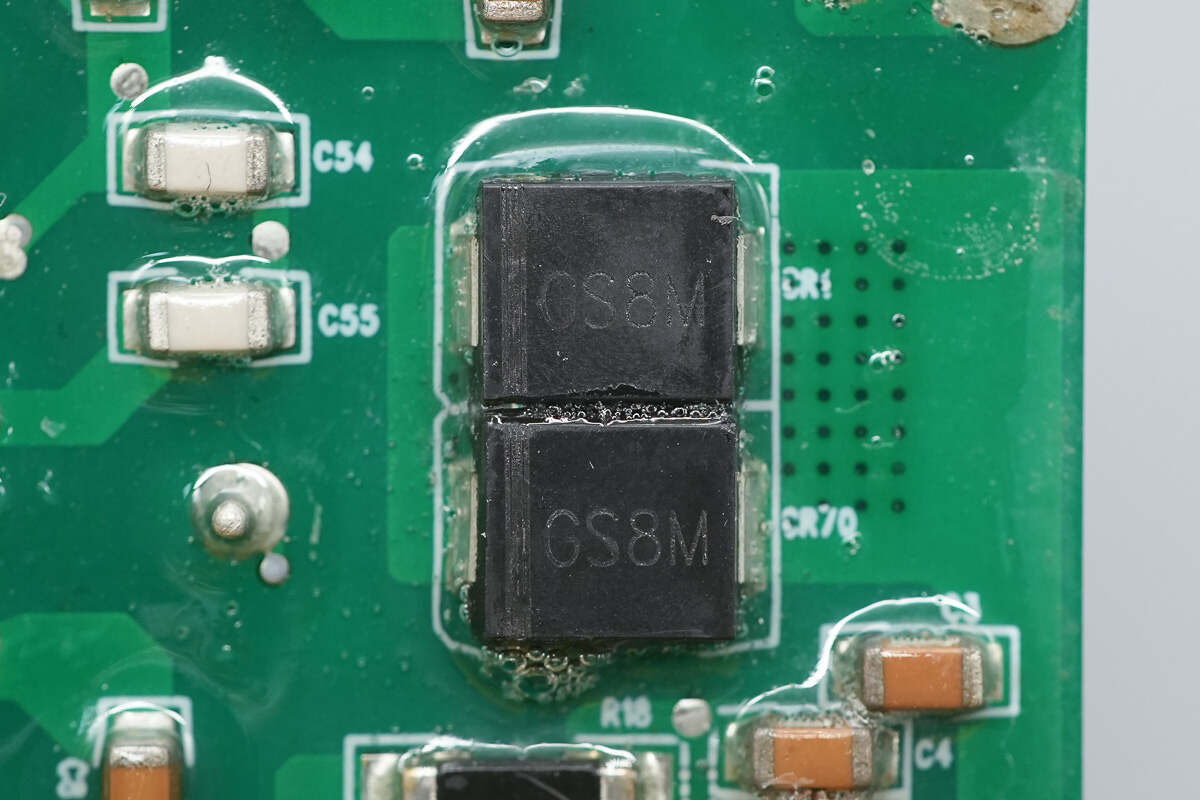
The PFC bypass diodes are marked with GS8M.
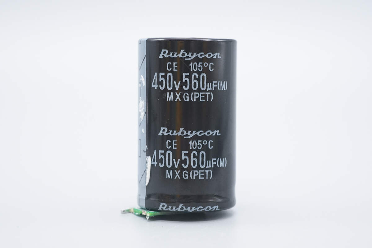
The high-voltage filter capacitor is from Rubycon, part of the MXG series electrolytic capacitors, with a rating of 450V 560μF.
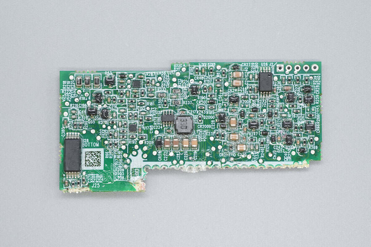
On the outer side of the control PCB, there is a digital isolation chip, a synchronous buck converter chip, operational amplifiers, and a memory chip.
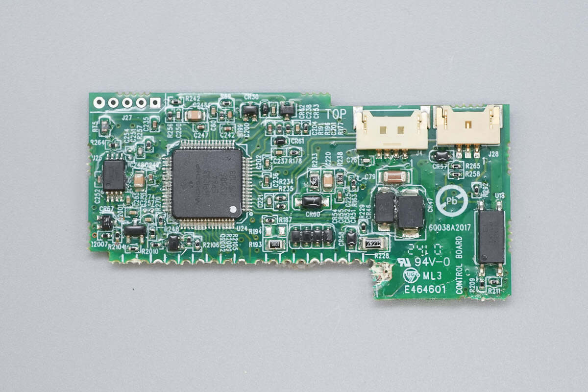
On the inner side, there are the LLC controller, memory chip, and optocoupler.
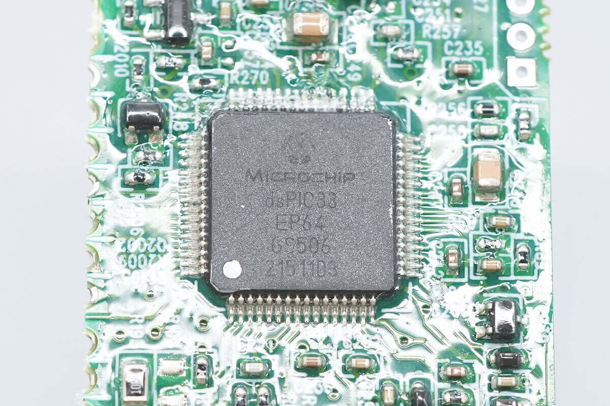
The LLC controller is from Microchip, model dsPIC33EP64GS506. It features a built-in 16-bit dsPIC33E CPU, 64KB of FLASH memory, and 8KB of RAM. It integrates a high-speed PWM generator and a high-speed ADC, and comes in a TQFP64 package.
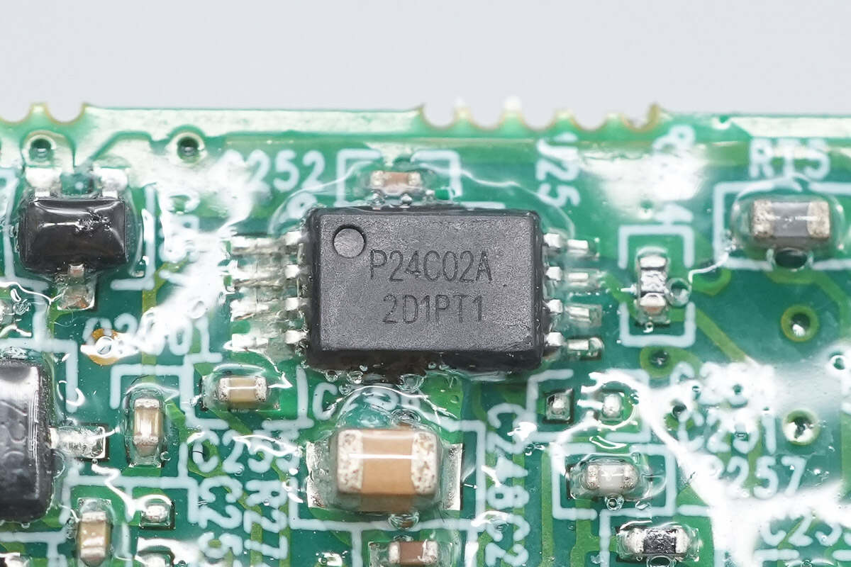
The memory chip is from Puya, model P24C02A, with a capacity of 256 bytes, packaged in a TSSOP8 case.
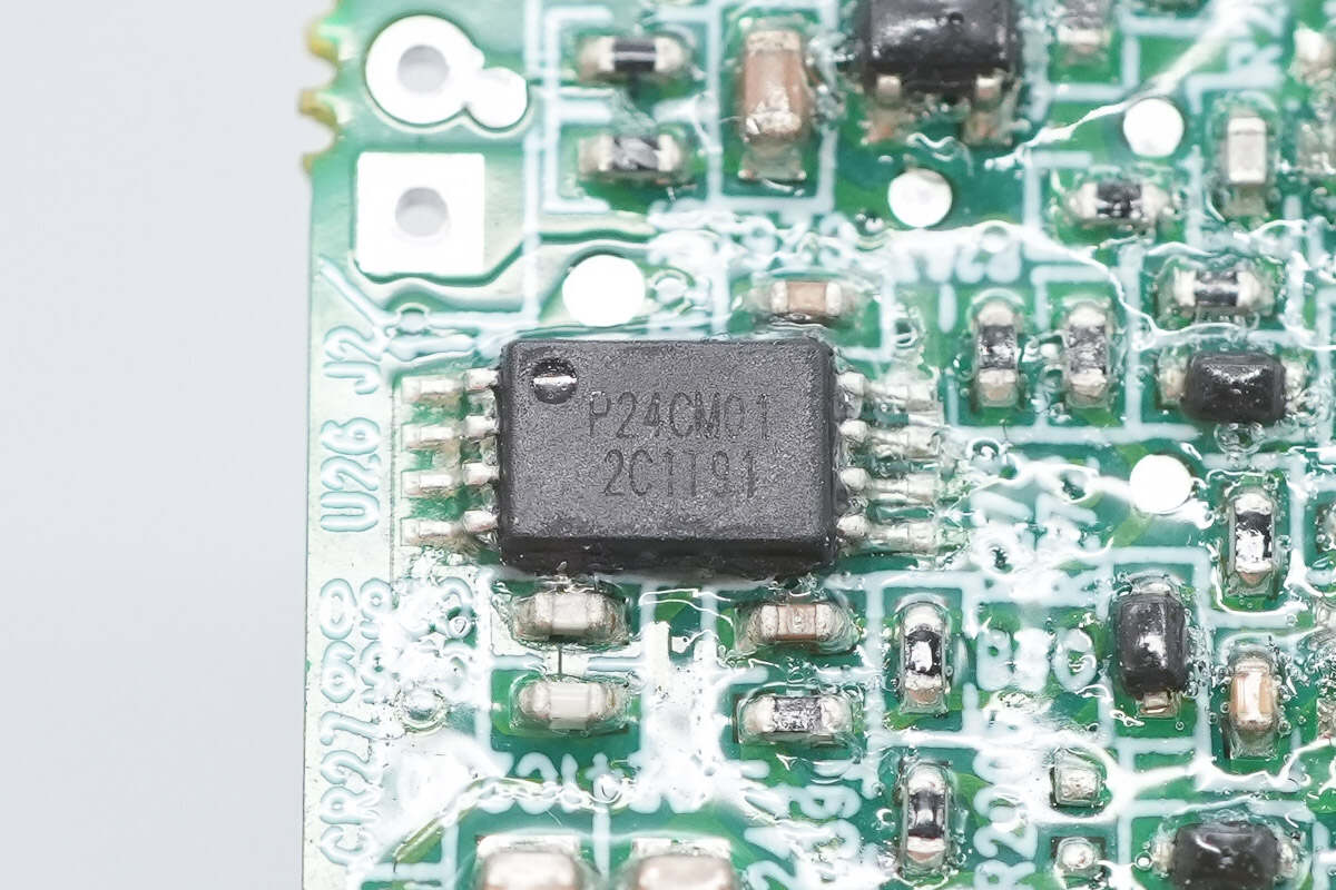
The other memory chip is model P24CM01, with a capacity of 128KB, also packaged in a TSSOP8 case.
The synchronous buck chip is from MPS, model MP2314S.
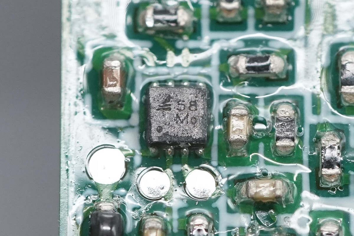
The operational amplifier is from 3PEAK, marked with 58, model LM358A. It is a high-voltage amplifier featuring low offset, low power consumption, and stable frequency response. The package type is DFN 1.5×1.5-8.
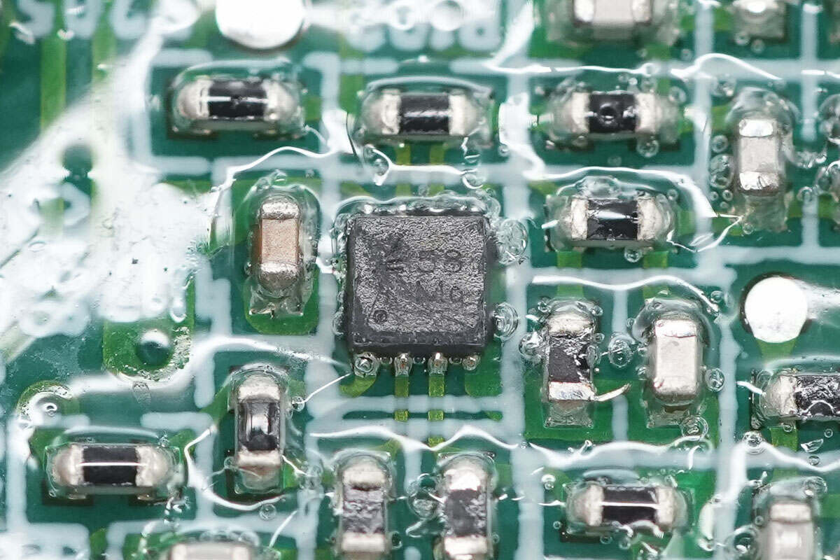
The other operational amplifier has the same model.
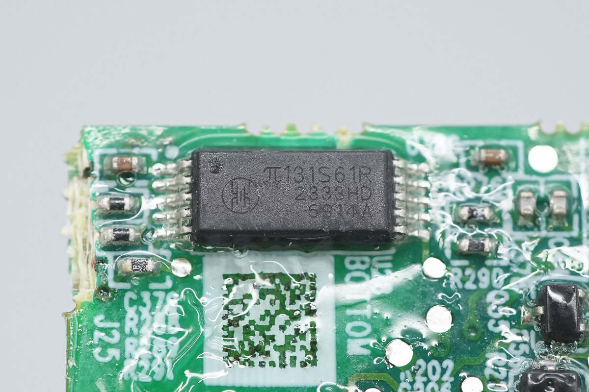
The digital isolation chip is from rpsemi, model π131S61R. It is a 3-channel bidirectional digital isolation chip, supporting an operating voltage of 2.5–5.5V and a data transmission rate of 2Mbps. It comes in a WB SSOIC-10 package.
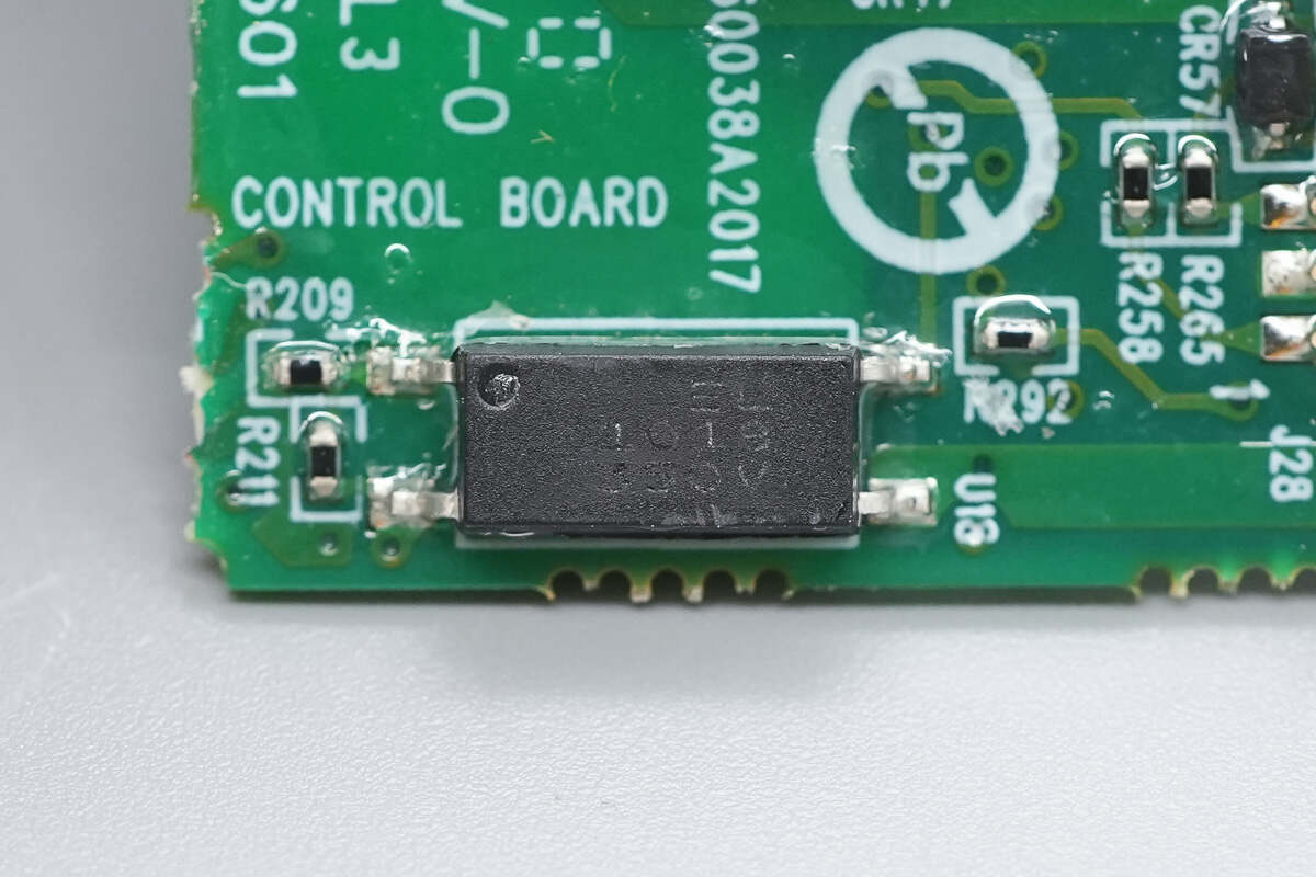
Close-up of the Everlight EL1018 optocoupler.
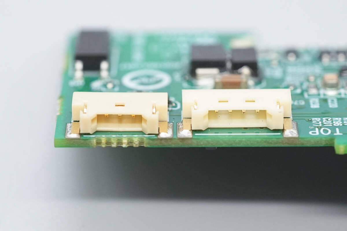
Close-up of the connectors used for the indicator light and cooling fan.
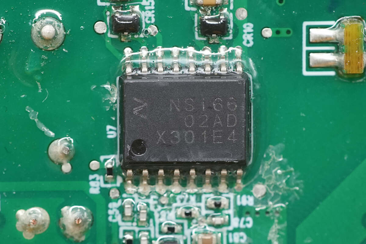
The isolation driver is from NOVOSENSE, model NSi6602AD. It is an isolated dual-channel gate driver with 5.7kVrms isolation capability, featuring 4A sourcing current and 6A sinking current, packaged in an SOW16 case.
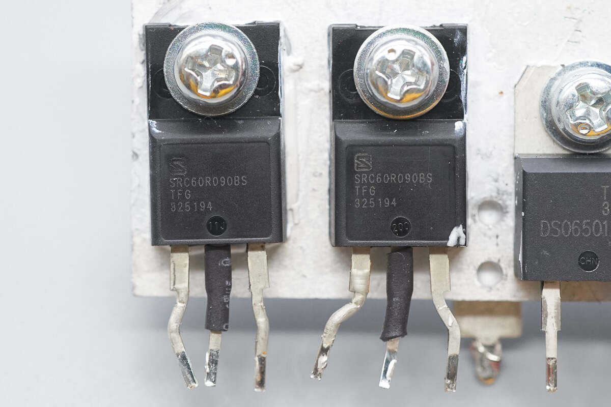
The LLC MOSFETs are from Sanrise, model SRC60R090BS. They are NMOS transistors with a voltage rating of 600V and an on-resistance of 90mΩ, packaged in a TO-220F case.
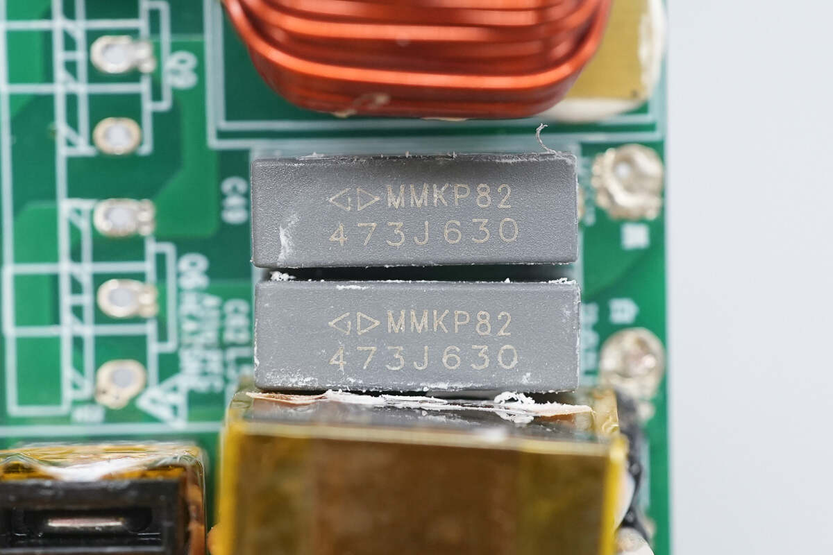
The resonant capacitors are from Faratronic, with a specification of 0.047μF, 630V.
The current transformer is insulated with high-temperature adhesive tape.
The resonant inductor is wound with Litz wire.
The transformer primary winding is made with Litz wire, while the secondary winding uses soldered copper strips. The magnetic core is insulated with wrapped tape.
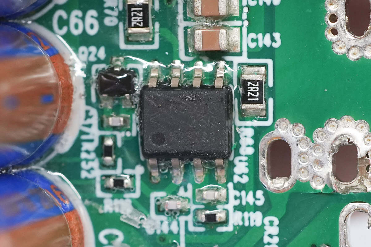
The driver for the synchronous rectifiers is from 3PEAK, model NSD1025-Q1. It is an automotive-grade high-speed dual-channel low-side driver with 5A sourcing and sinking current capability, featuring two independent gate driver channels. The package type is EP-SOP8.
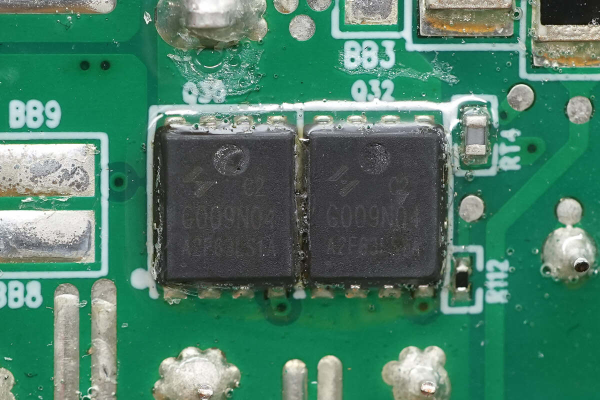
The synchronous rectifiers are from HUAYI, model HYG009N04LS1C2. They are NMOS transistors with a voltage rating of 40V and an on-resistance of 0.75mΩ, packaged in a PDFN 5×6-8L case.
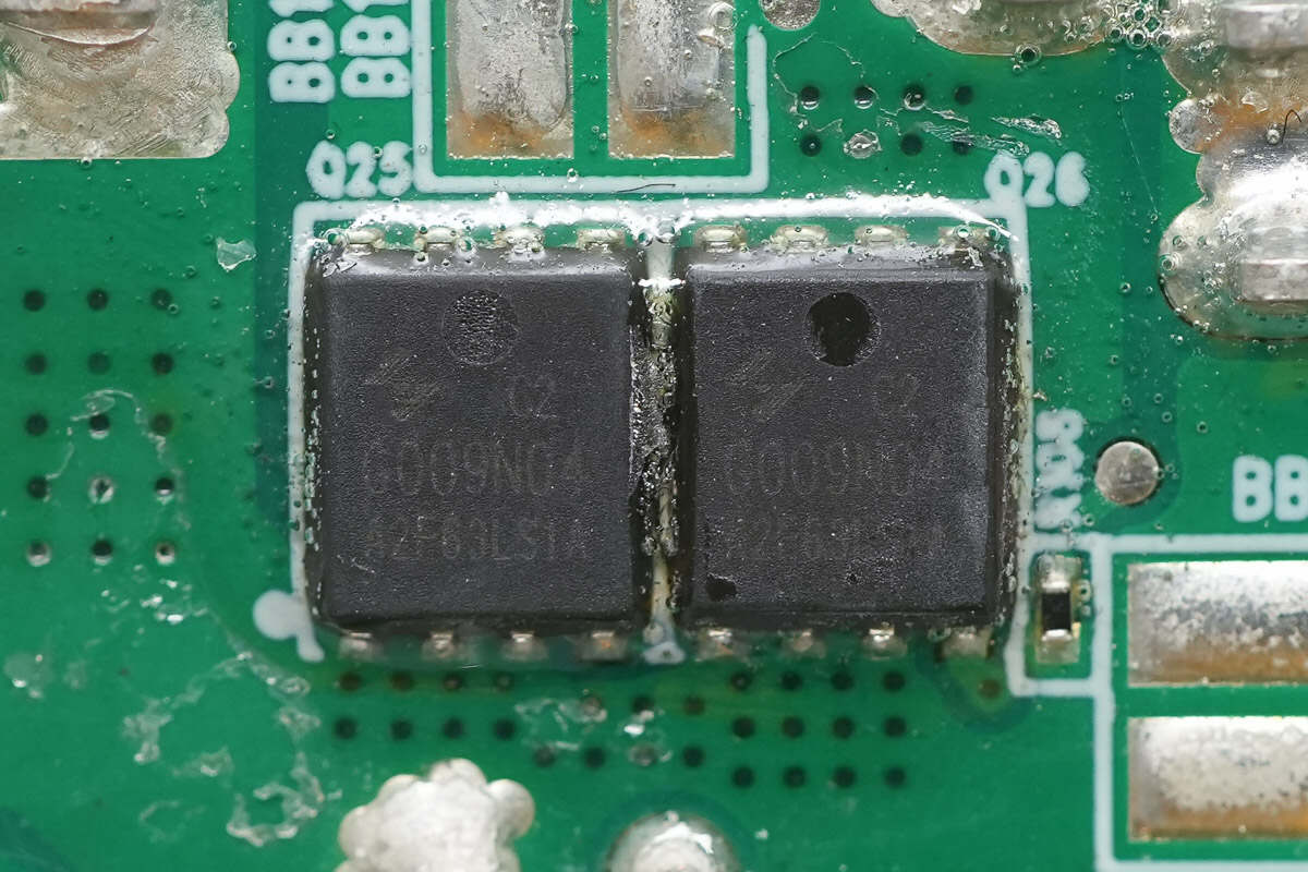
The other two synchronous rectifiers have the same model.
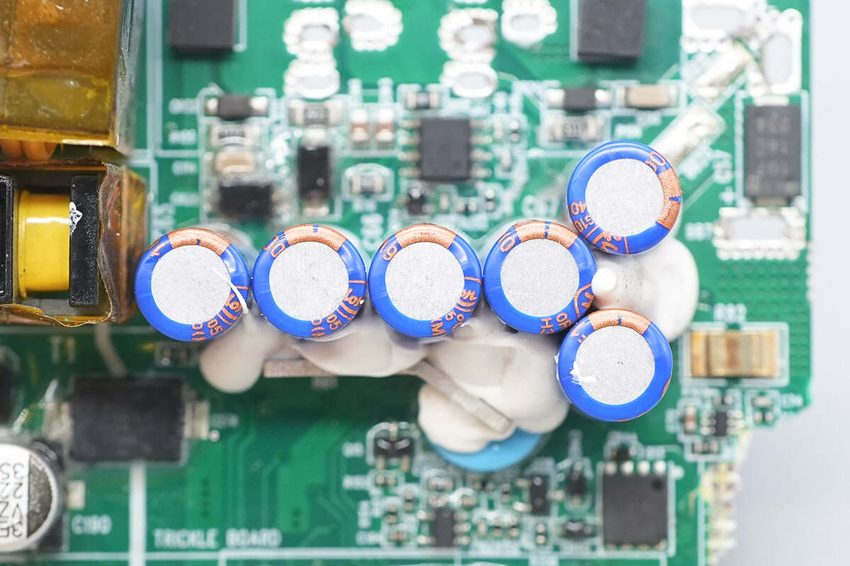
Six filter capacitors are secured with adhesive glue for reinforcement.
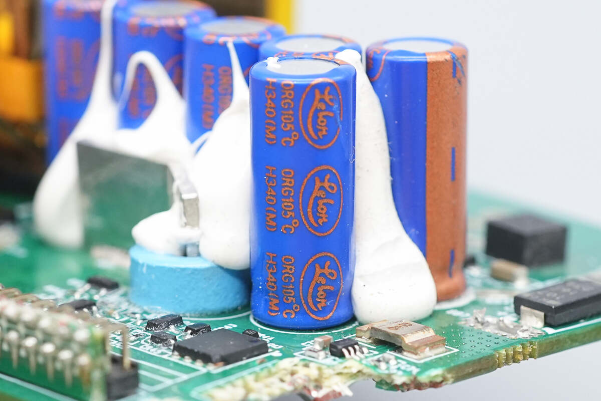
The filter capacitors are from Lelon, part of the ORG series of polymer solid aluminum electrolytic capacitors.
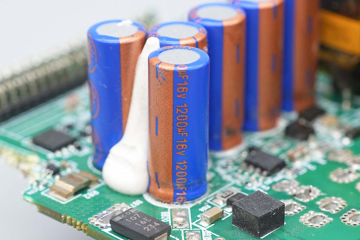
All are rated at 1200μF, 16V.
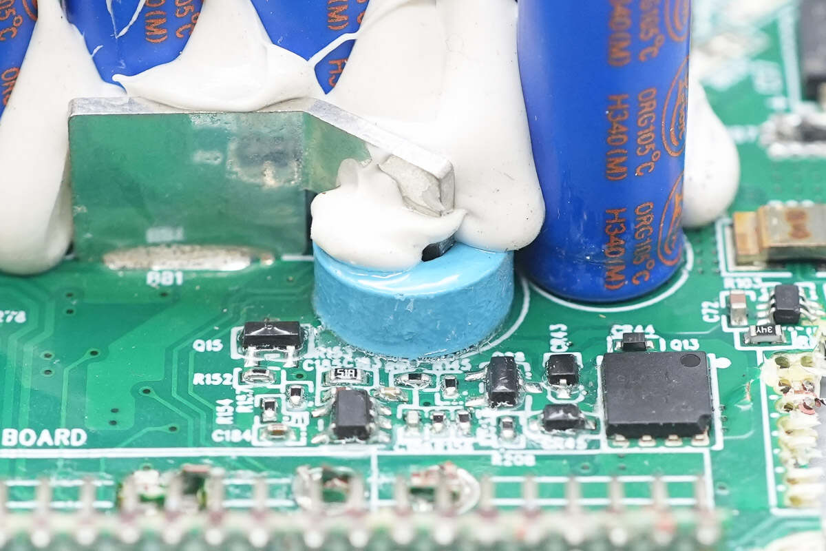
Close-up of the ferrite core filter inductor.
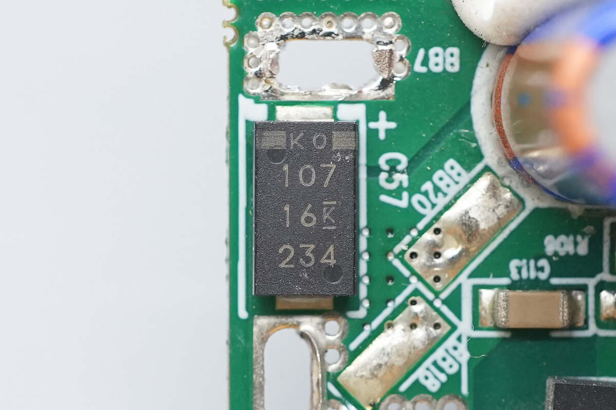
The filter capacitor is from KEMET, rated at 100μF, 16V.
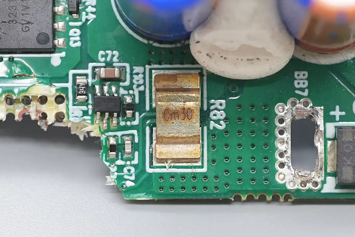
The 0.3mΩ shunt resistor is used for output current sensing.
The current sensing chip is from 3PEAK, model TP181A3. It is a zero-drift, bidirectional current-sense amplifier that supports a 36V input voltage and a 30V supply voltage. It comes in an SC70-6 package.
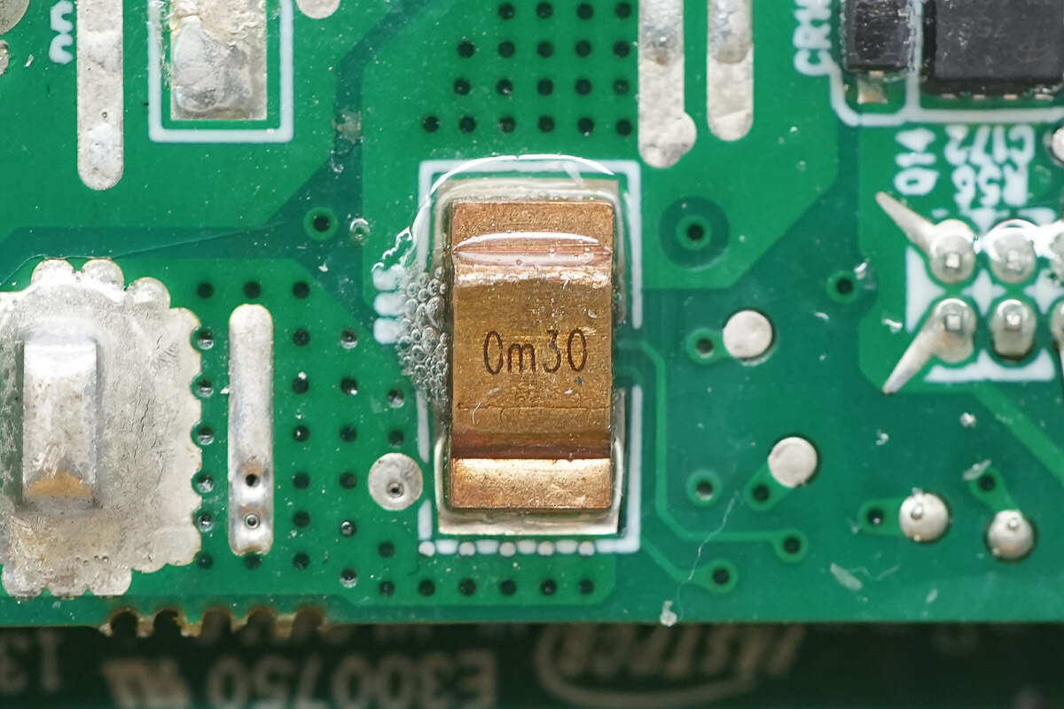
There is also a 0.3mΩ shunt resistor located on the back side.
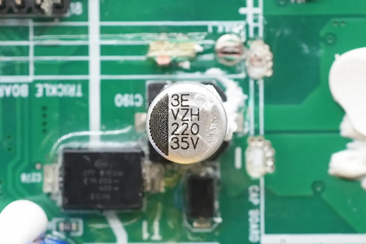
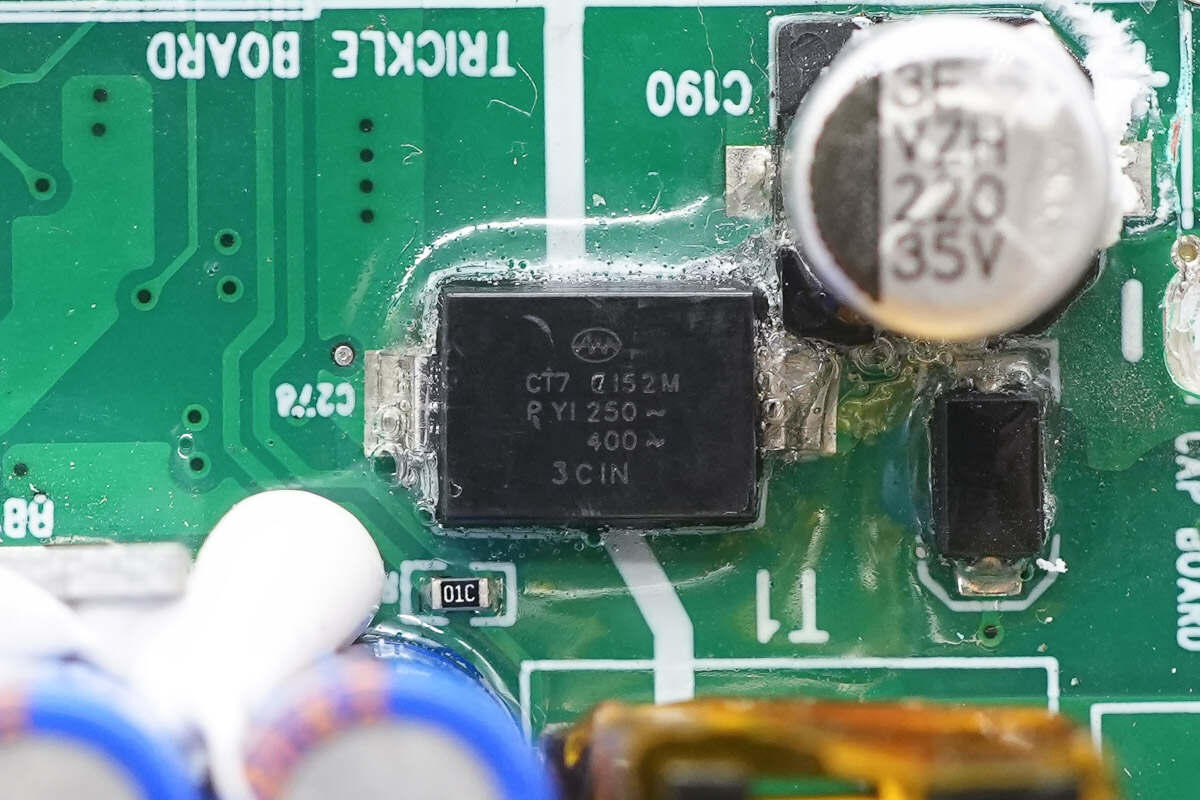
The filter capacitor is rated at 220μF, 35V.
The SMD Y capacitor is from KeiFat.
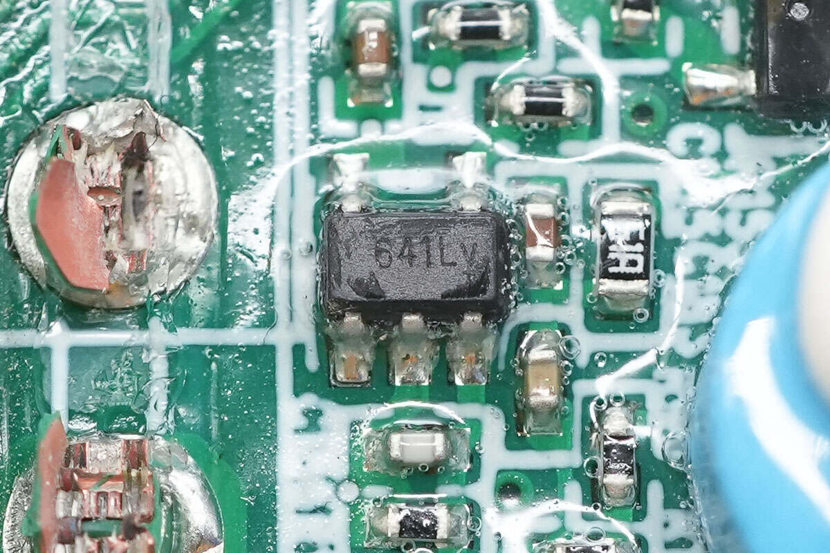
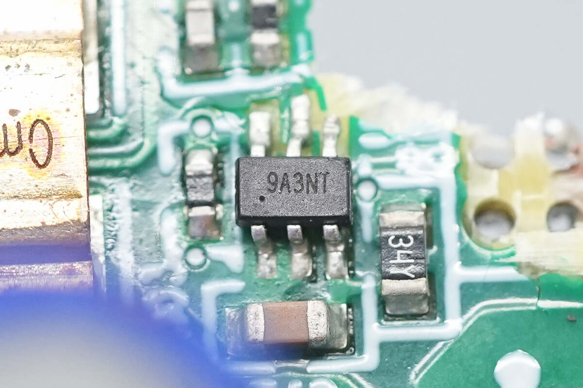
The operational amplifier is from 3PEAK, model TPA2641. It features a 2mV offset voltage, low power consumption, and strong immunity to high-frequency power supply noise. It comes in a SOT23-5 package.
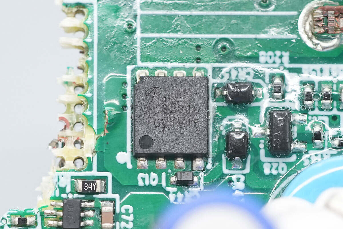
The power control MOSFET is from AOS, model AONS32310. It is an NMOS transistor rated for 30V with an on-resistance of 0.8mΩ. It is designed for high-performance ORing, e-fuse, and high-current battery protection board applications. The package type is DFN 5×6.
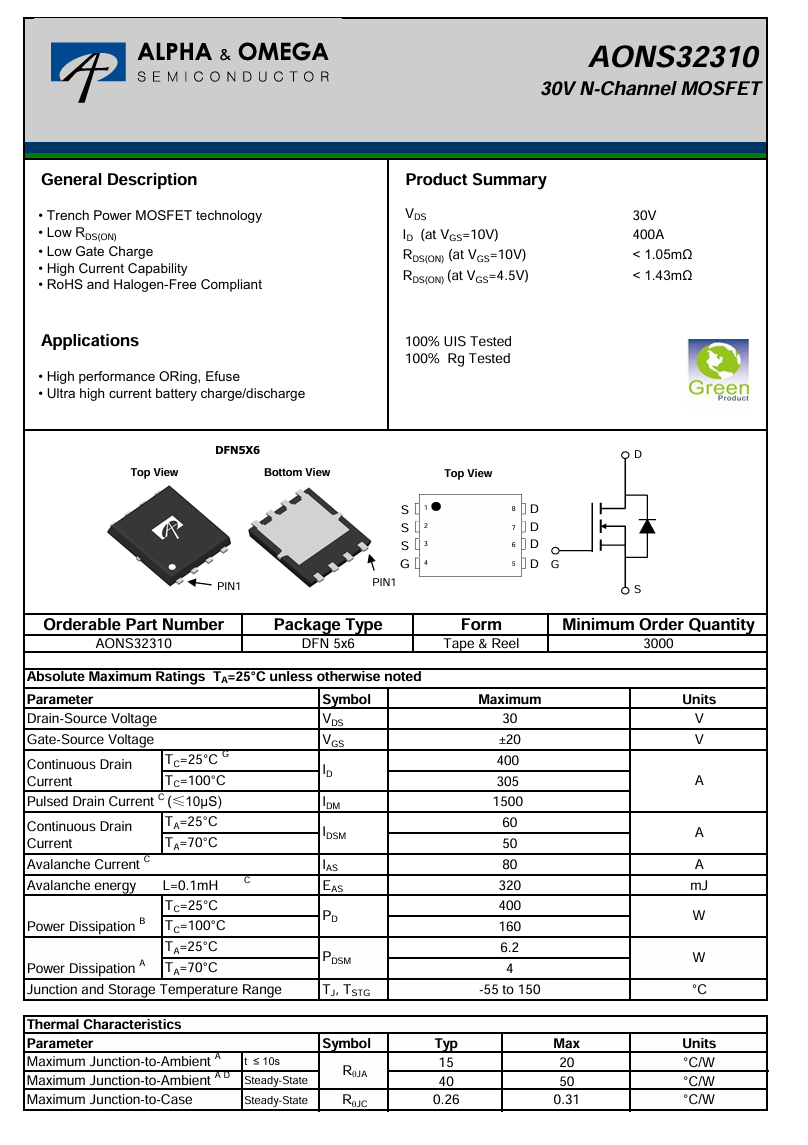
Here is the information about AOS AONS32310.
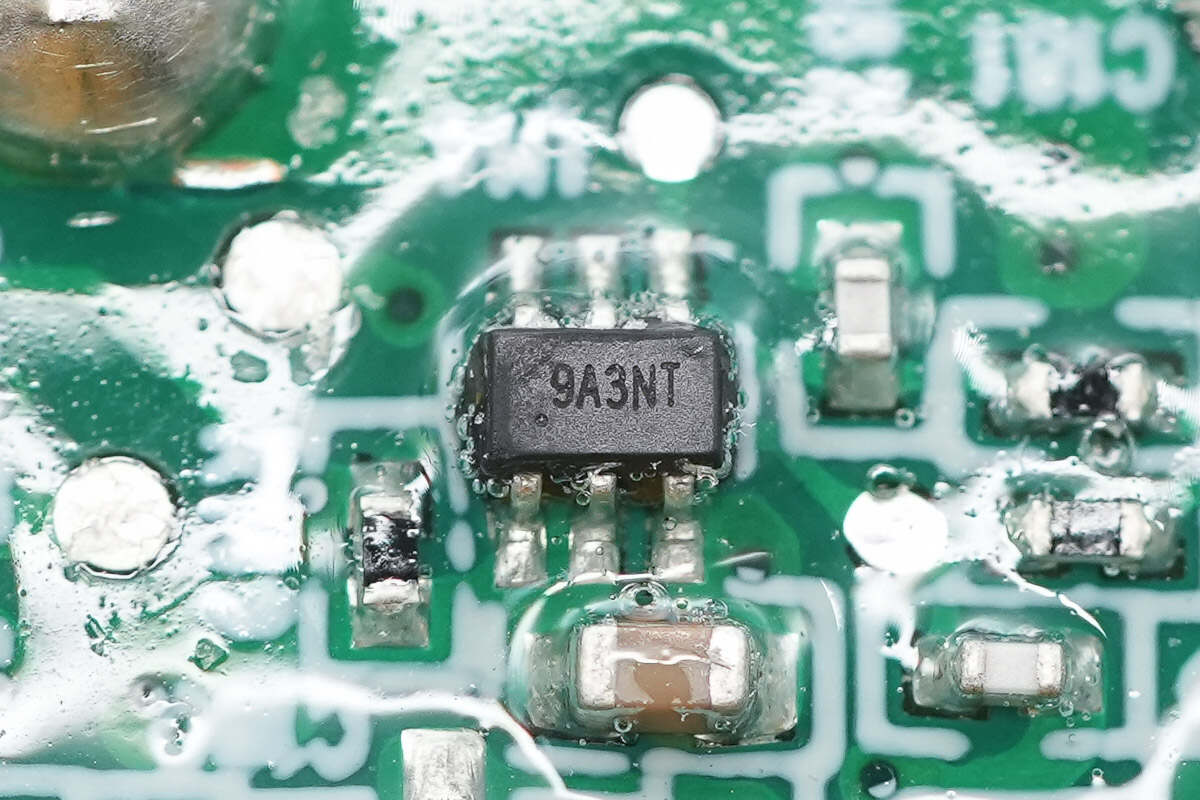
The current sensing chip is from 3PEAK, model TP181A3.
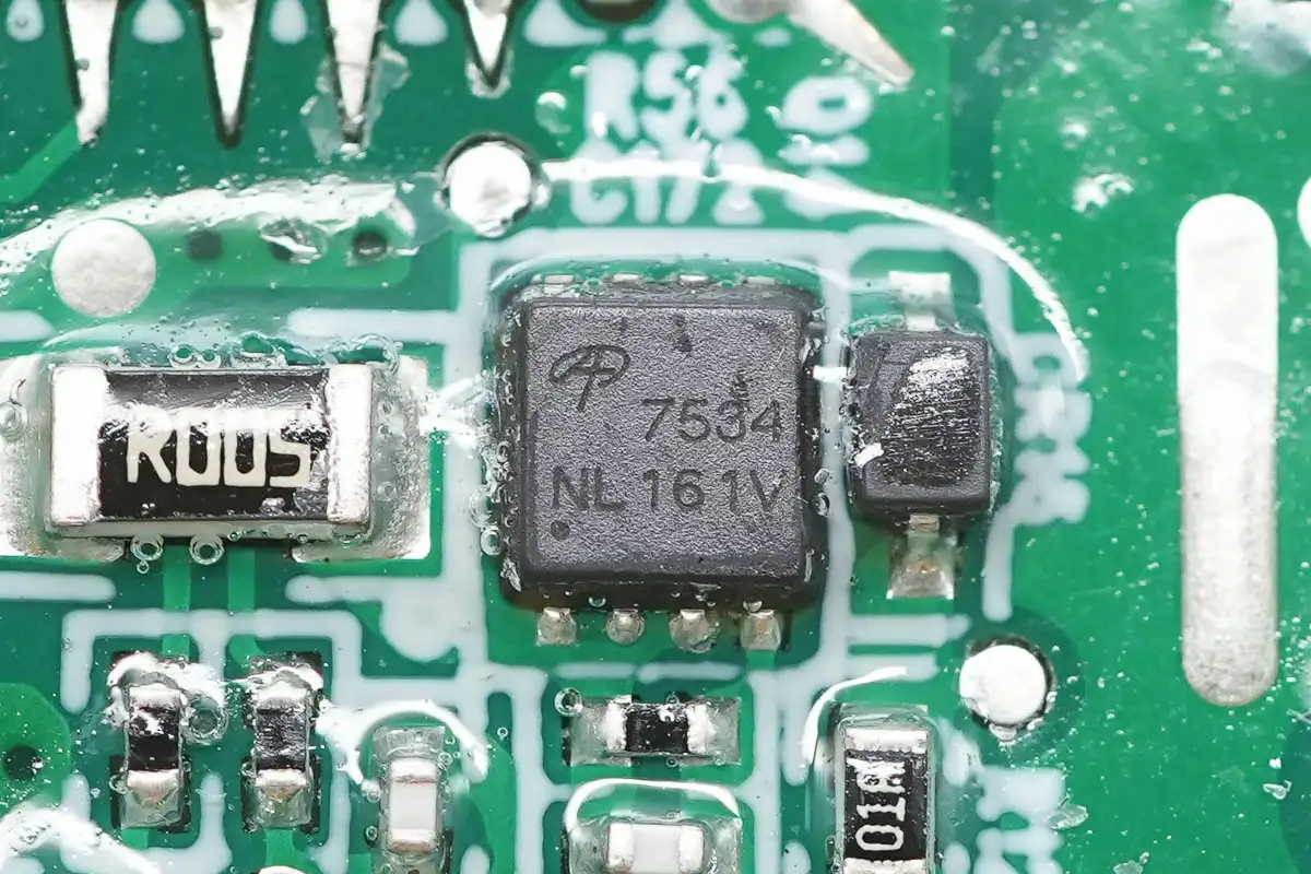
The power control MOSFET is from AOS, model AON7534. It is an NMOS transistor rated for 30V with an on-resistance of 4.1mΩ. It features low gate charge and high current handling capability, making it suitable for DC/DC converter applications. The package type is DFN 3×3 EP.
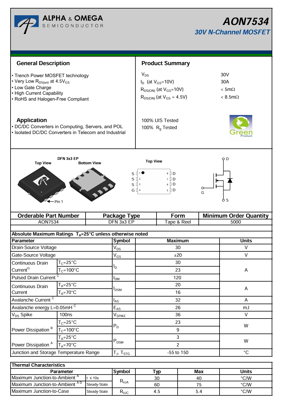
Here is the information about AOS AON7534.
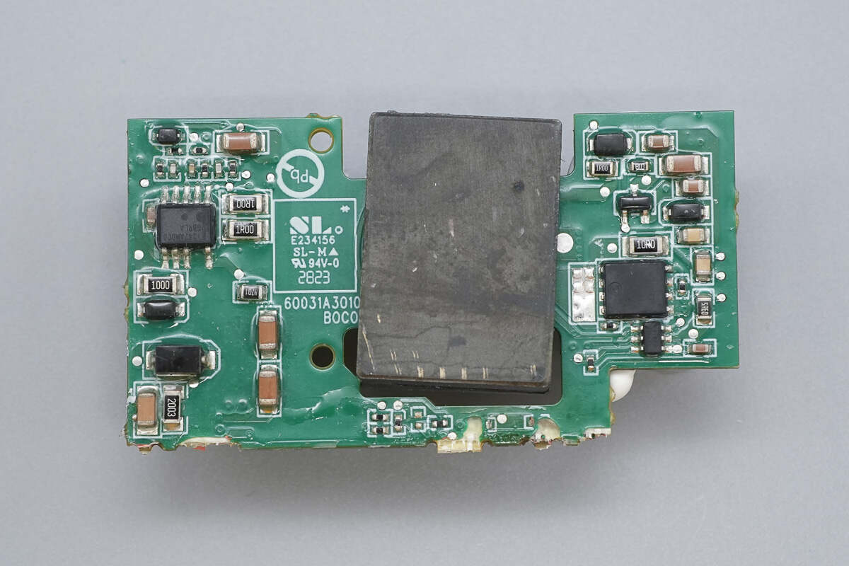
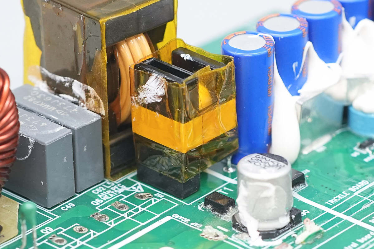
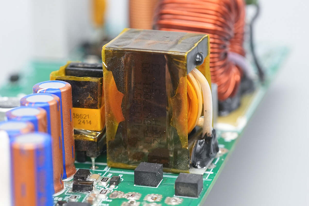
On the standby power PCB, the left side houses the primary controller, while the right side contains the synchronous rectifier controller and the synchronous rectifier.
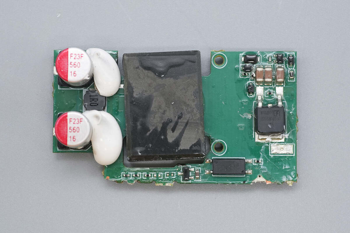
The back side features the primary MOSFET, optocoupler, and filter capacitors.
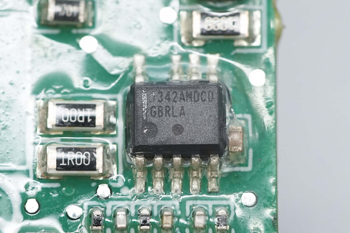
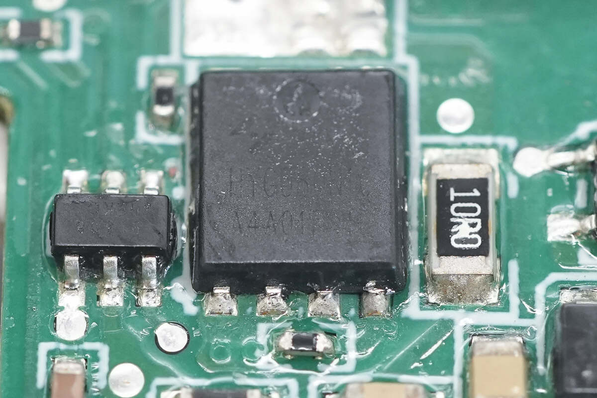
The primary controller is from Onsemi, model NCP1342. It is a high-frequency quasi-resonant flyback primary PWM controller featuring built-in high-voltage startup, active X2 capacitor discharge, wide Vcc supply range, external thermistor support for over-temperature protection, and multiple comprehensive protection functions. It comes in an SOIC-9 NB package.
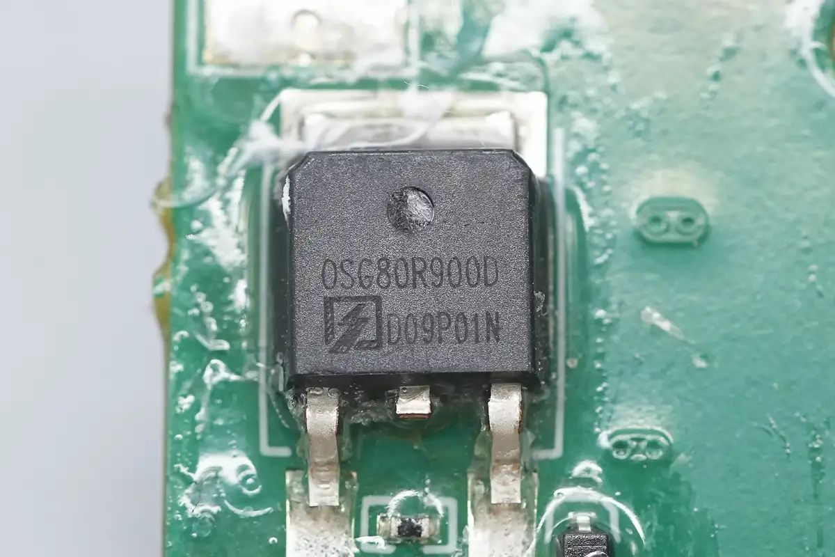
The primary MOSFET is from Oriental, model OSG80R900DF. It is an NMOS transistor rated for 850V with an on-resistance of 900mΩ, packaged in a TO-252 case.
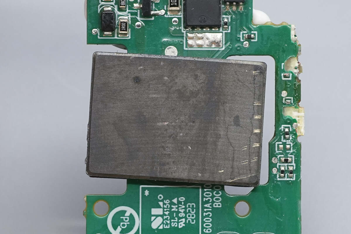
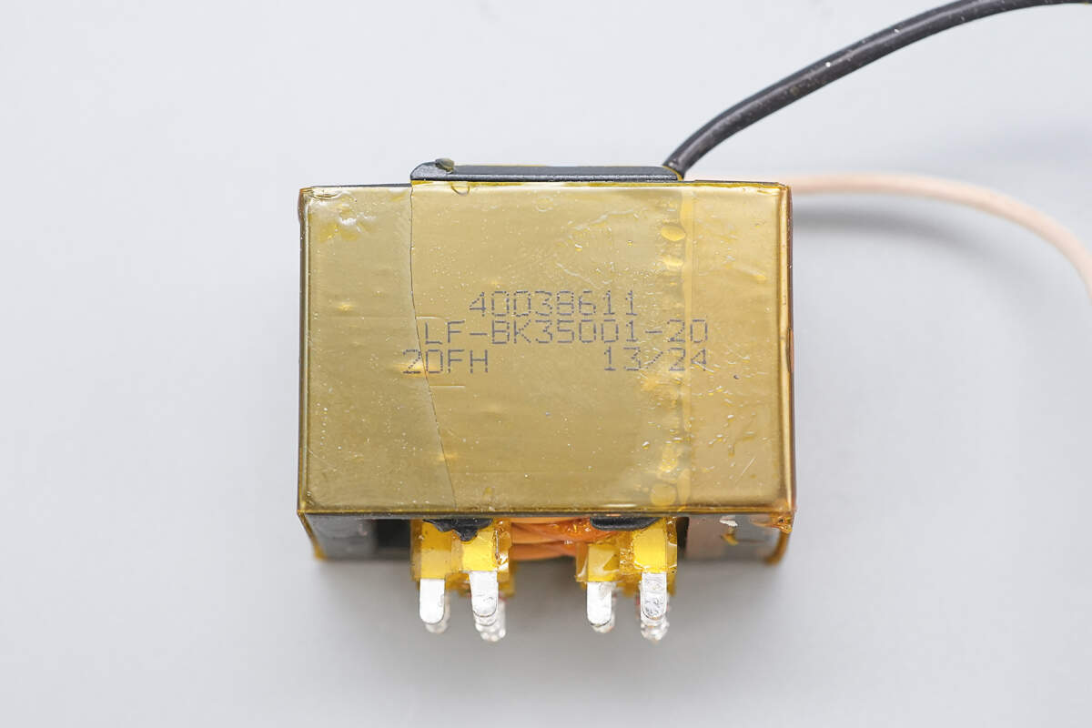
Close-up of the planar transformer core.
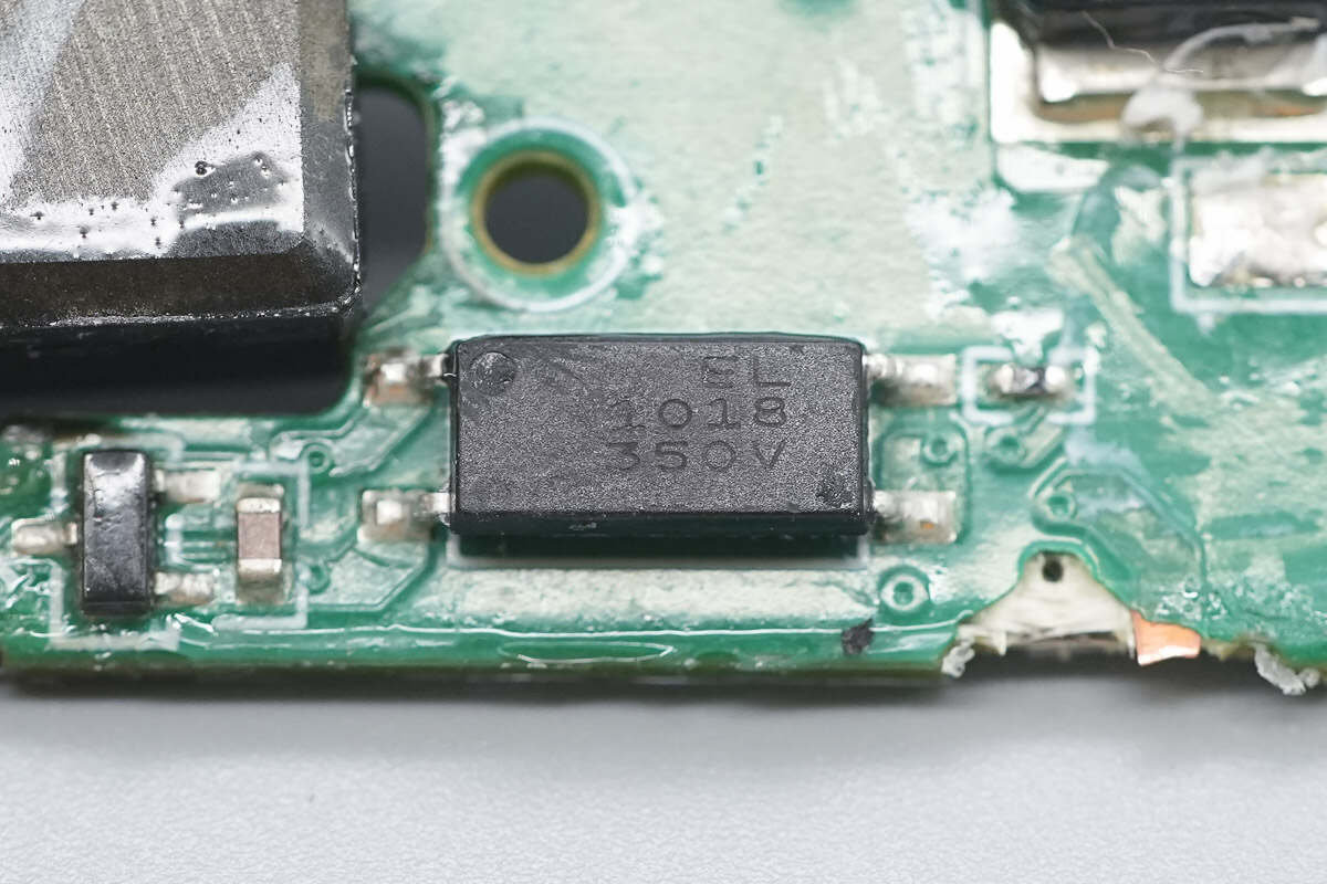
The Everlight EL1018 optocoupler is used for output voltage feedback.
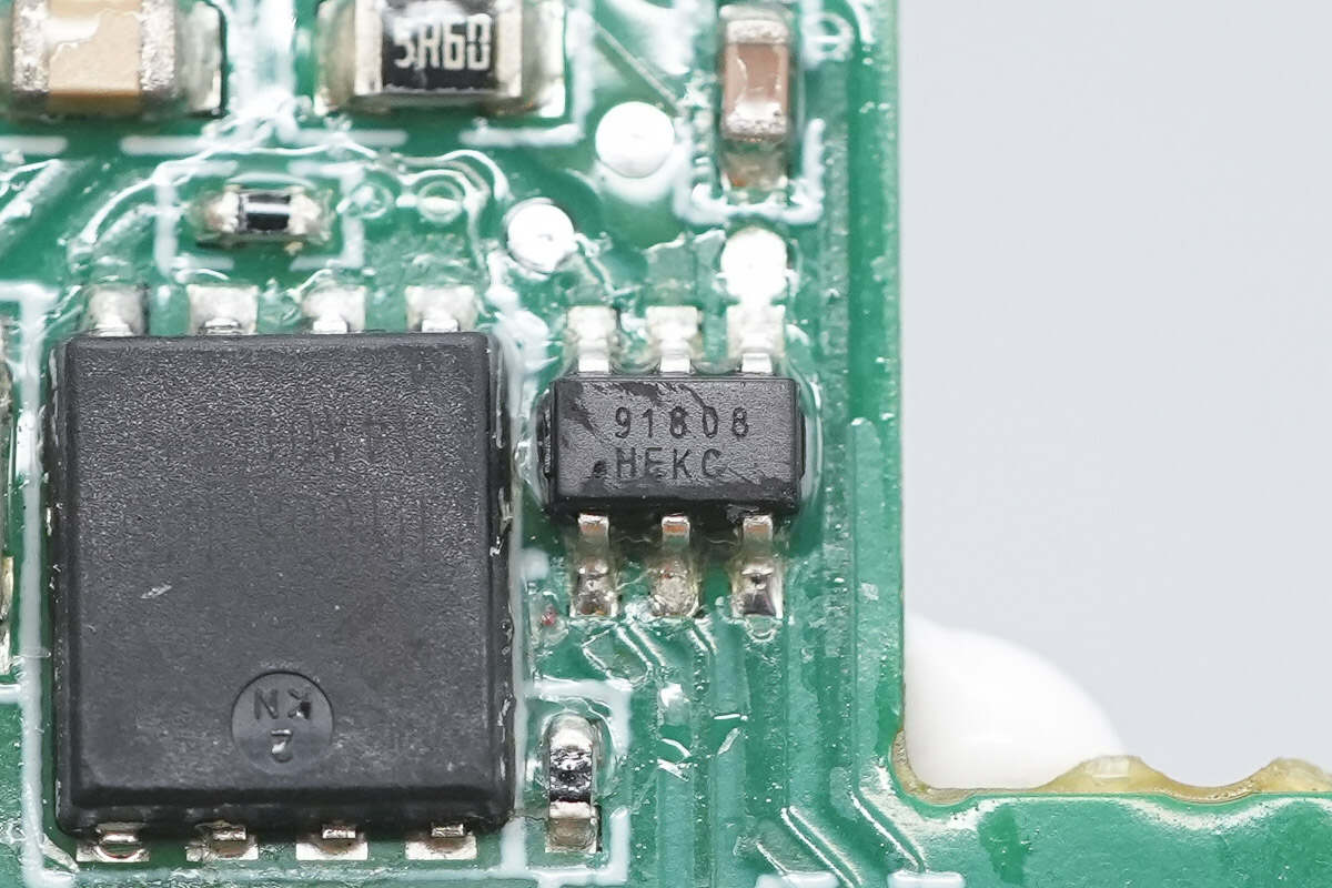
The synchronous rectifier controller is from Meraki, model MK91808H. It supports CCM, DCM, and QR operating modes. The chip uses proprietary self-powered technology to supply VCC and can be directly placed on the positive rail without requiring an auxiliary winding. It comes in an SOT23-6 package.
The synchronous rectifier is from HUAYI, model HYG080N10LS1C2. It is an NMOS transistor rated for 100V with an on-resistance of 6.9mΩ, packaged in a PDFN 5×6-8L case.
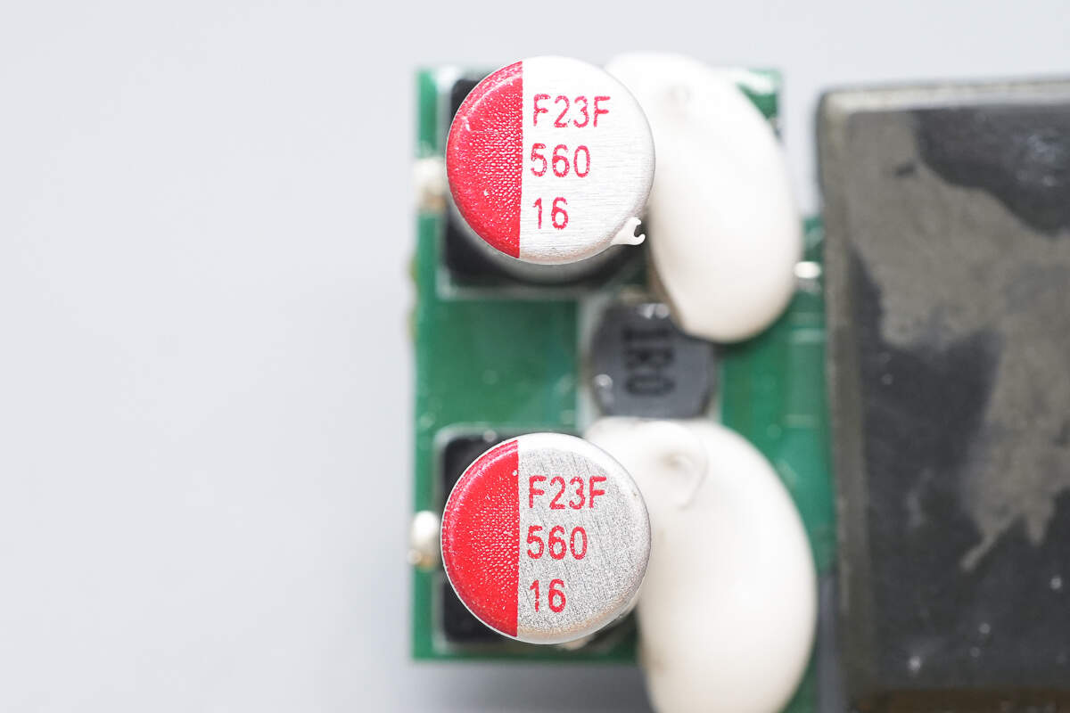
The two solid capacitors are rated at 560μF, 16V.
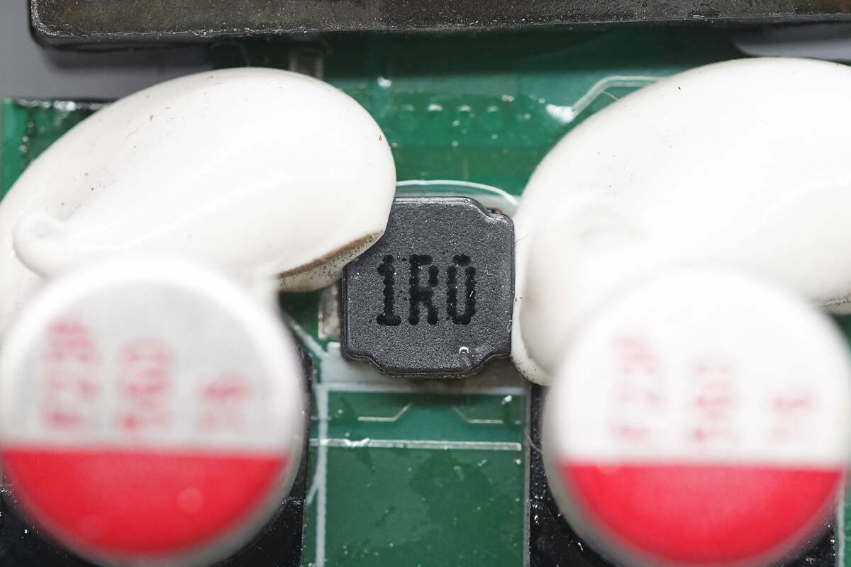
Close-up of the 1μH filter inductor.
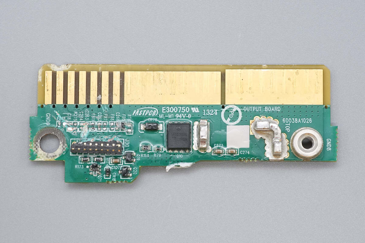
The gold finger PCB is connected via pin headers and copper bars, and features output control MOSFETs.
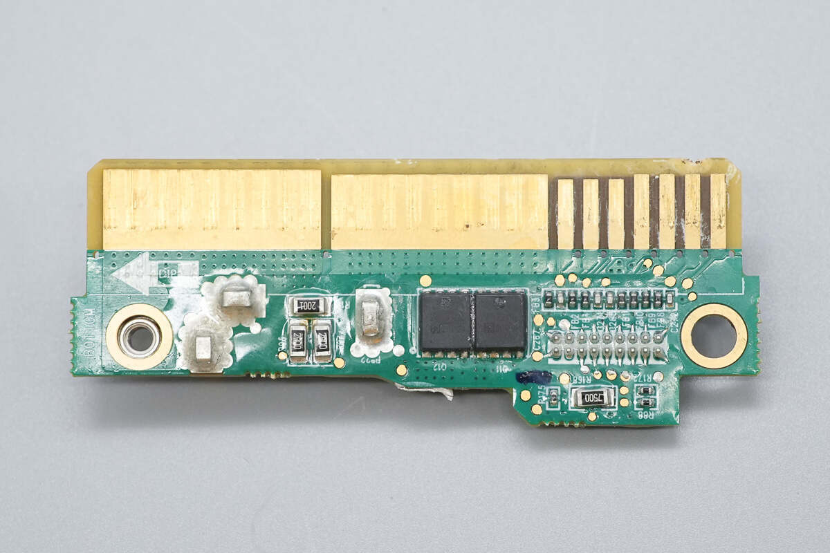
The other side also has two output control MOSFETs.
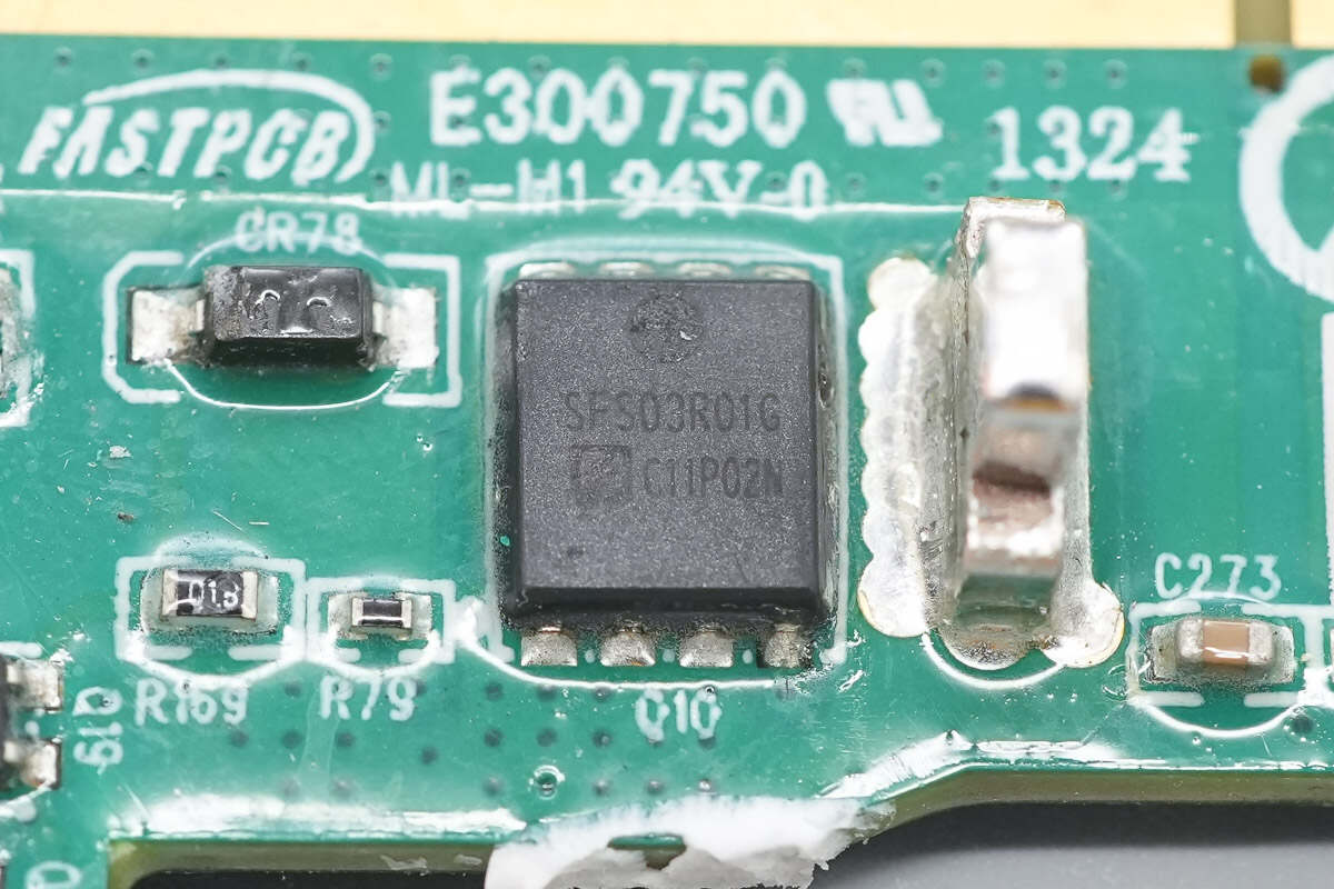
The output control MOSFETs are from Oriental, model SFS03R01GF. They are NMOS transistors rated for 25V with an on-resistance of 1.35mΩ, packaged in a PDFN 5×6 case.
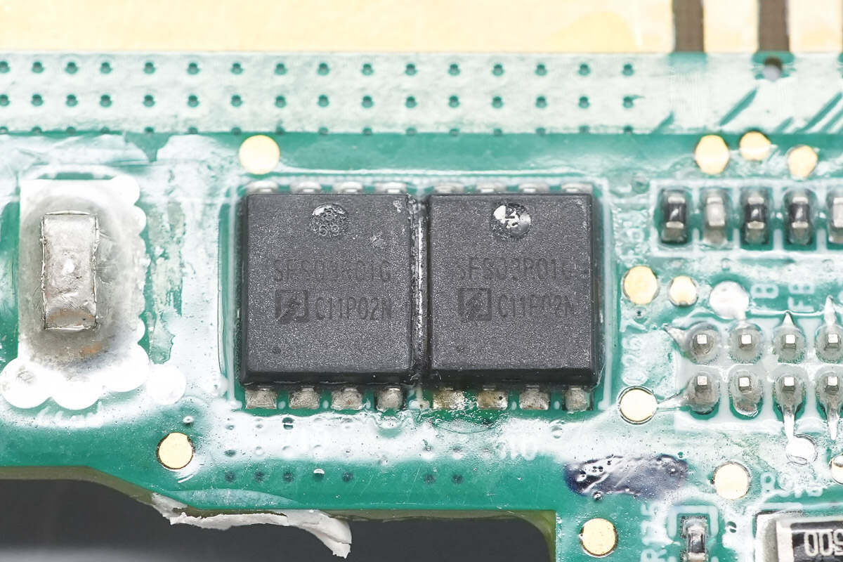
The other two output control MOSFETs have the same model.
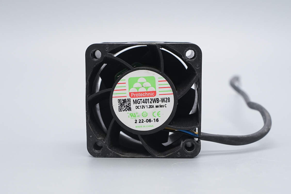
The cooling fan is from PROTECHNIC, model MGT4012WB-W28, rated at 12V 1.2A, made in China.
Well, those are all components of the Boco Electronics 800W SiC Server Power Supply.
Summary of ChargerLAB
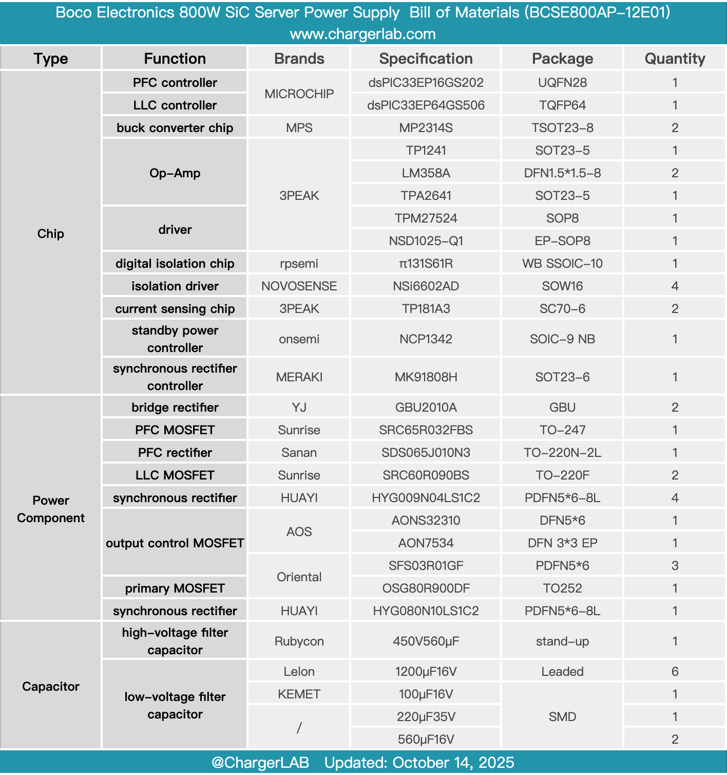
Here is the component list of the Boco Electronics 800W SiC Server Power Supply for your convenience.
It supports 100–240V AC input, with a rated output voltage of 12V and an output current of 66.7A. The standby power output is 12V with a rated current of 3A. The power supply module features a built-in cooling fan that draws air in from the output side and expels it through the input side for cooling.
After taking it apart, we found that it contains built-in Microchip controllers. The PFC controller is a dsPIC33EP16GS202, paired with a 3PEAK TPM27524 driver. The PFC MOSFET is a Sanrise SRC65R032FBS, and the silicon carbide diode is a Sanan SDS065J010N3.
The LLC controller is a dsPIC33EP64GS506, paired with NOVOSENSE NSi6602AD isolation drivers. The LLC MOSFETs are Sanrise SRC60R090BS. The synchronous rectifiers are HUAYI HYG009N04LS1C2, driven by a NOVOSENSE NSD1025-Q1 driver.
The standby power supply uses an Onsemi NCP1342 controller paired with an Oriental OSG80R900DF primary MOSFET, and a Meraki MK91808H synchronous rectifier controller paired with a HUAYI HYG080N10LS1C2 synchronous rectifier. The high-voltage filter capacitor is from Rubycon, while the low-voltage filter capacitors are from Lelon, supplemented by a KEMET tantalum capacitor. The control PCB and standby power PCB are vertically mounted to optimize space utilization. The workmanship and component selection are solid and reliable.
Related Articles:
1. Teardown of Lenovo 100W GaN Power Adapter (ADL100UAGC3A)
2. Teardown of UUGreenPower UR100020‑SW 20 kW Ultra‑Wide Voltage Constant Power Charging Module
3. Teardown of Dell 280W USB-C GaN AC Adapter (LA280PM240)