Introduction
Belkin has launched a new auto-tracking charging stand featuring Apple’s DockKit facial tracking technology. With a motorized base and an integrated wireless charging pad, the stand enables 360° horizontal and 90° vertical dynamic facial tracking — making it ideal for live streaming, vlogging, outdoor selfies, and other content creation scenarios.
The device includes a built-in rechargeable battery that provides up to 5 hours of additional runtime, ensuring flexibility for on-the-go use. The magnetic charging pad incorporates Apple’s MFM-certified MagSafe module, delivering authentic 15W wireless charging for iPhones when connected to a power source — perfectly suited for everyday charging needs. In this teardown, we’ll take a closer look inside to explore the internal components and engineering behind this innovative product.
Product Appearance
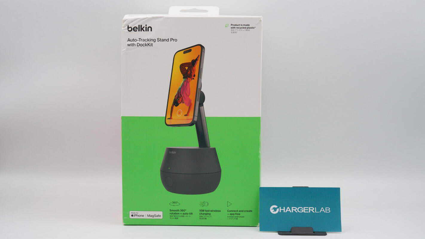
The front of the packaging features the Belkin logo, the product name, usage scenario imagery, key selling points, and the MFM certification mark.

The back of the packaging displays usage scenarios and a description of the product’s features.
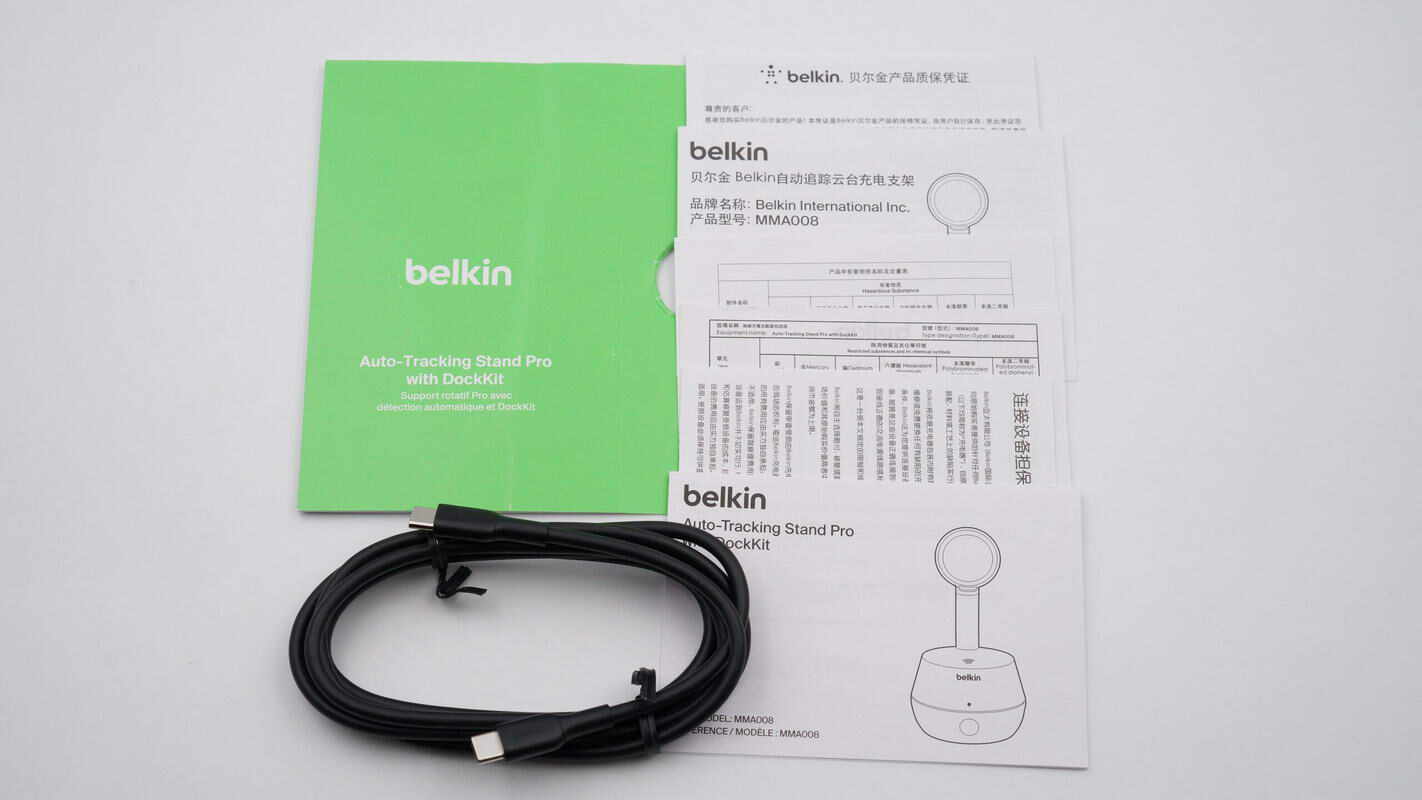
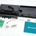
Inside the packaging, in addition to the charging stand, there is a charging cable, a user manual, and a warranty card.
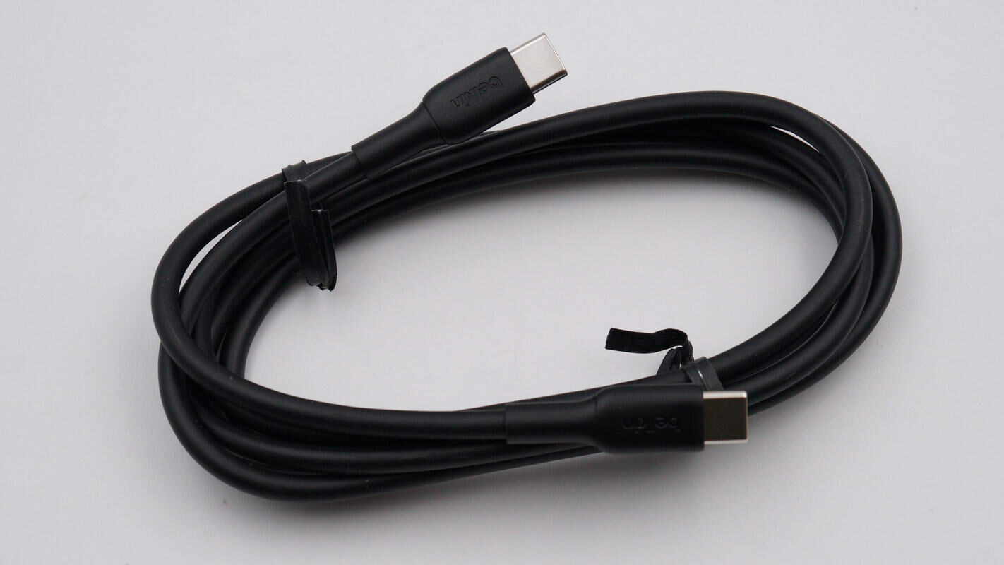
The included charging cable is a USB-C to USB-C type.
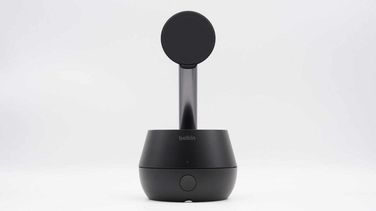
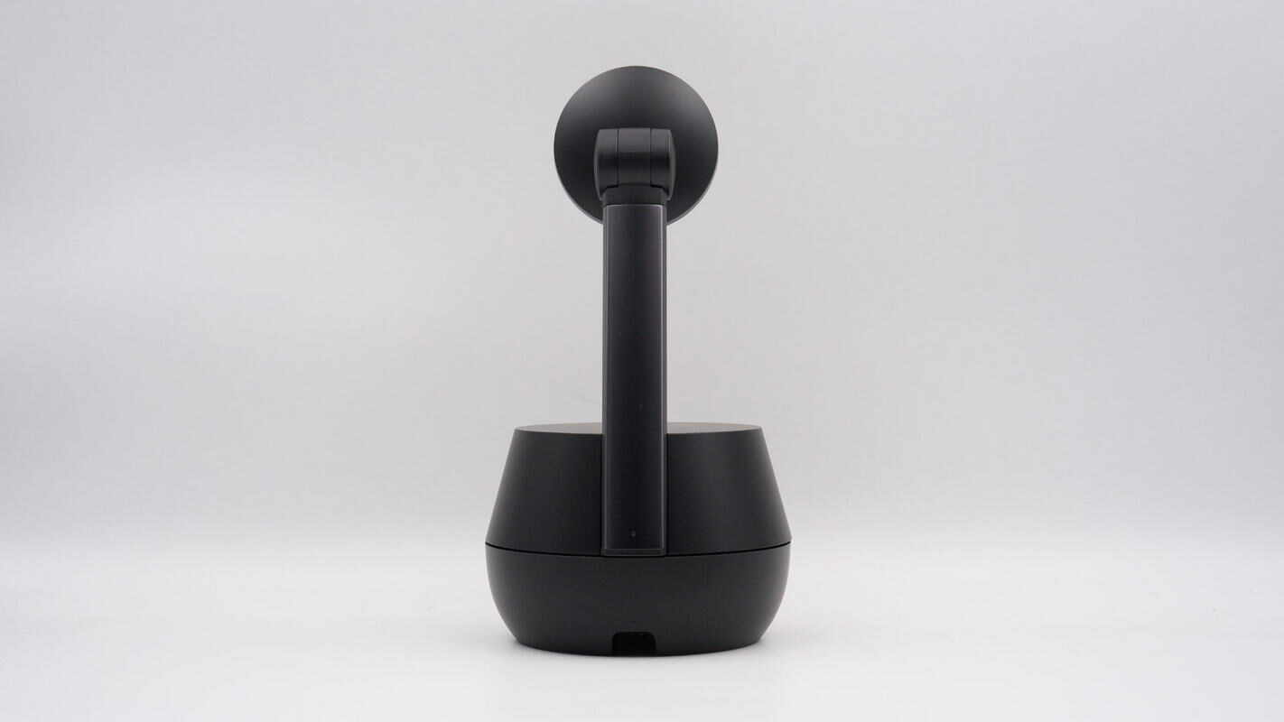
The charging stand is composed of three parts: the base, the support rod, and the MagSafe wireless charging pad. The base rotates 360° horizontally and, combined with Apple’s DockKit facial tracking technology, is designed to meet the needs of live streaming, outdoor selfies, vlogging, and other content creation scenarios.
The casing is made from renewable plastic materials, reflecting Belkin’s commitment to low-carbon and environmentally friendly practices.
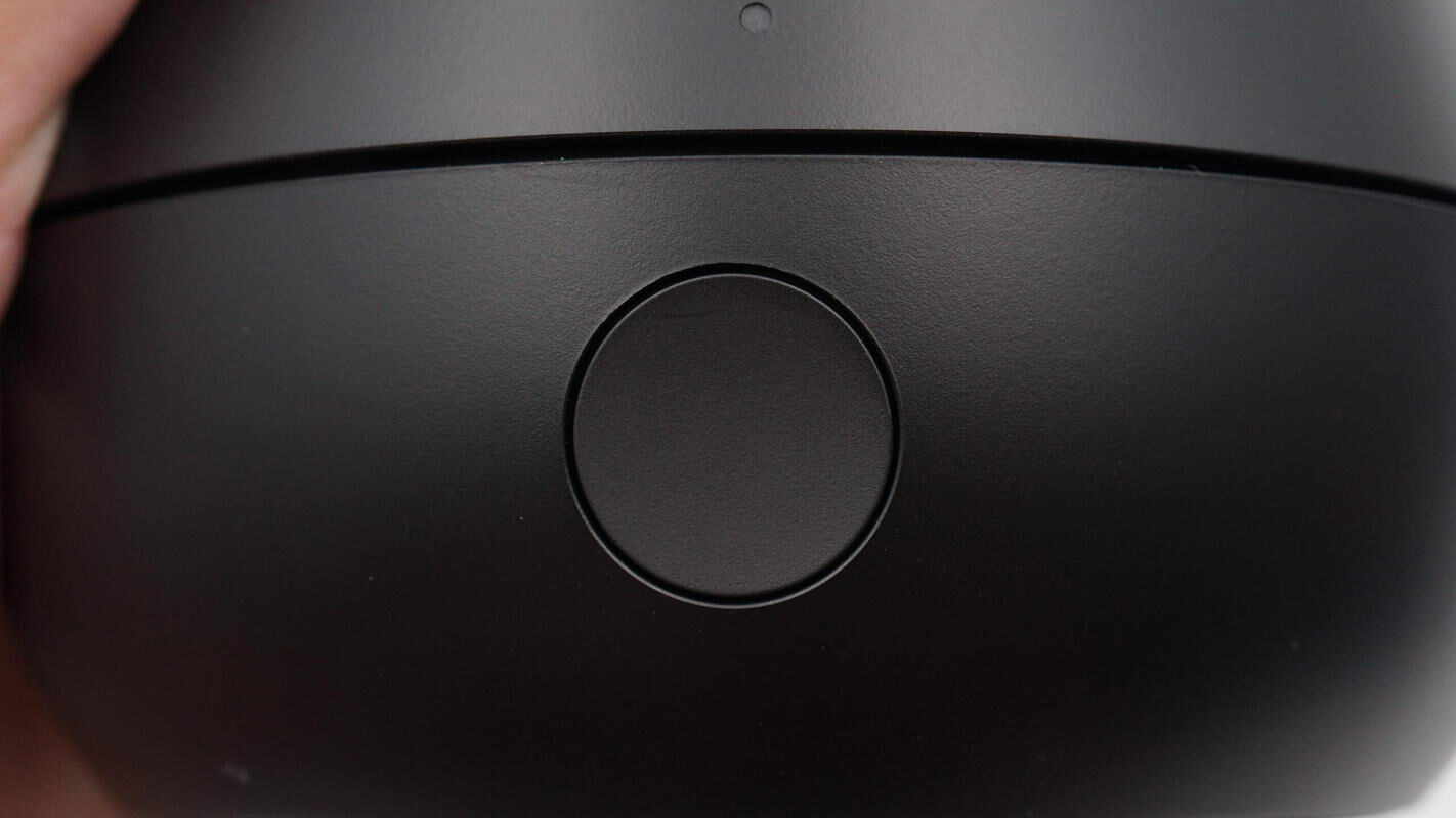
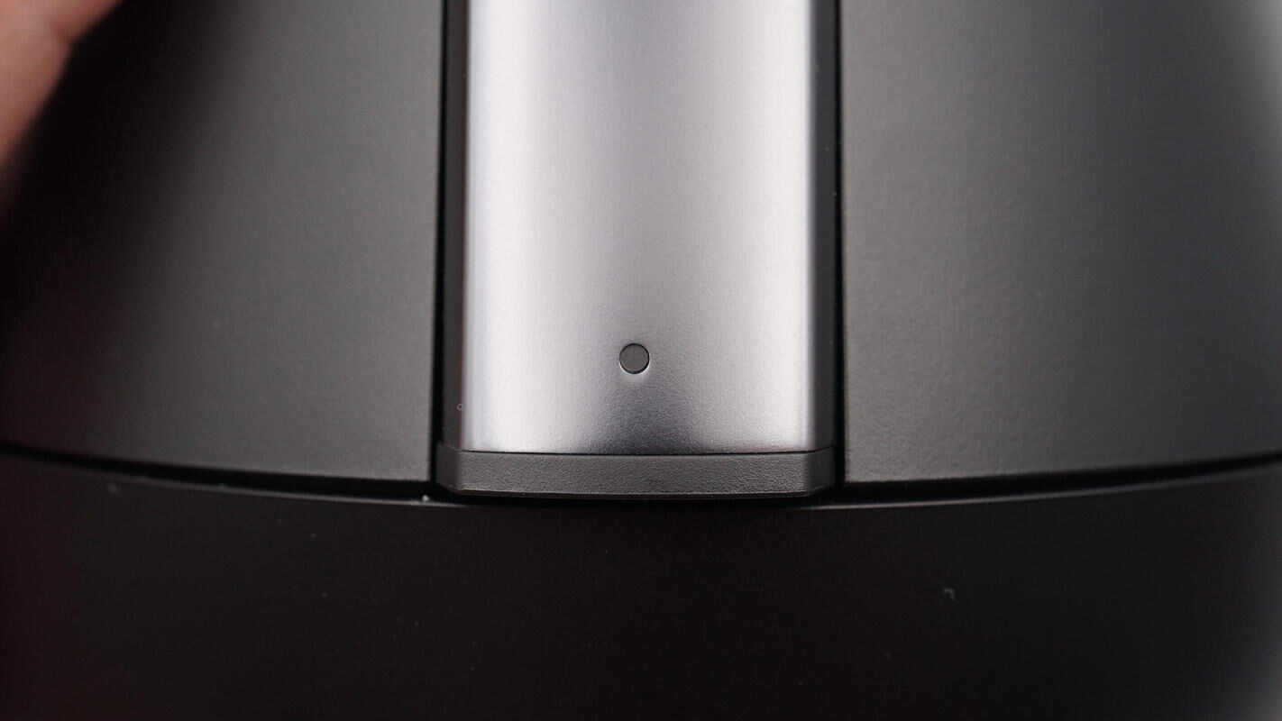
The front of the base features a button to start and stop the auto-tracking function.
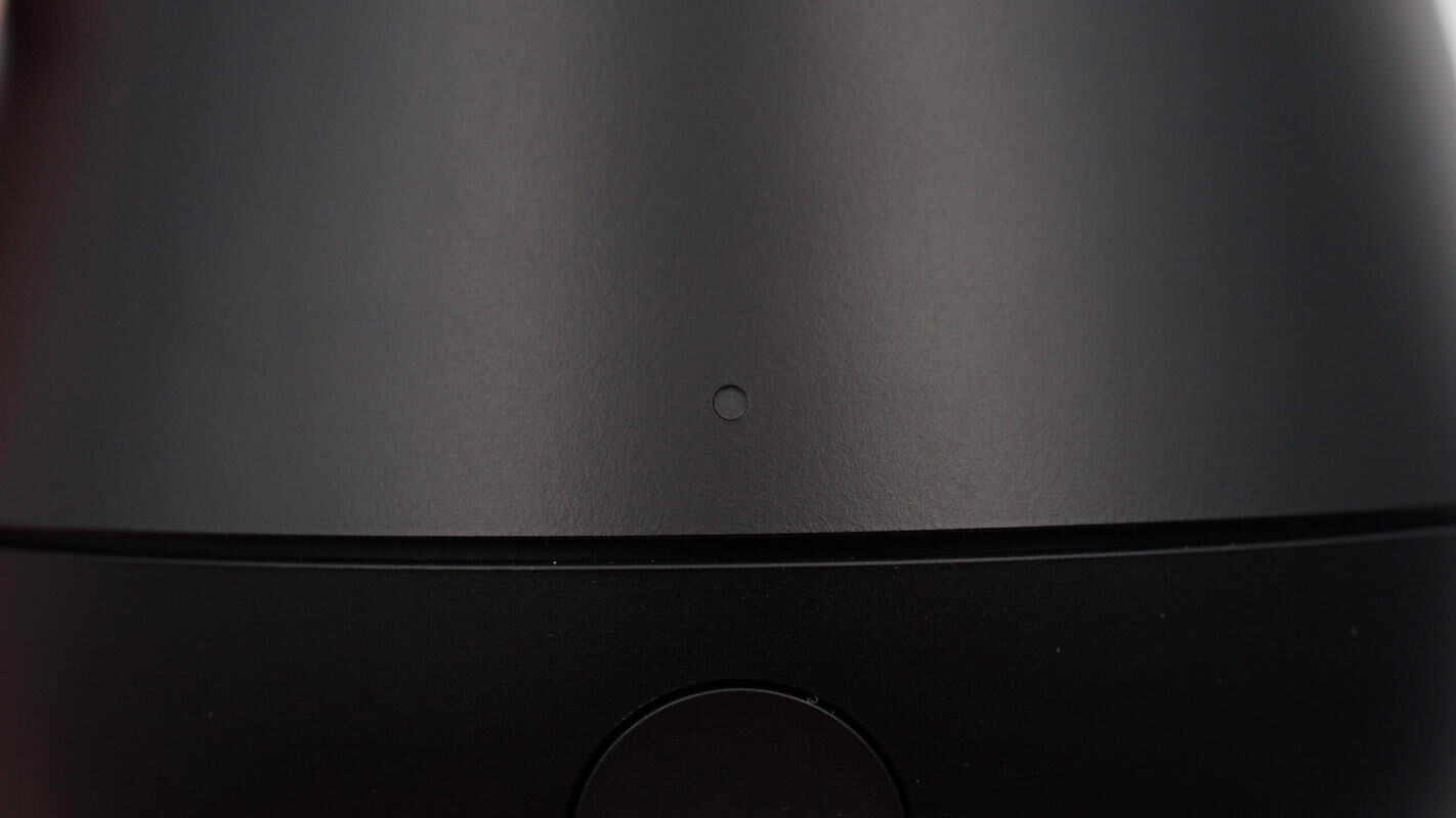
Above the button is an LED indicator light. A flashing white light indicates NFC pairing in progress, while a steady white light means pairing is successful. A flashing green light signals that facial tracking is active, and a steady green light indicates tracking is ready.
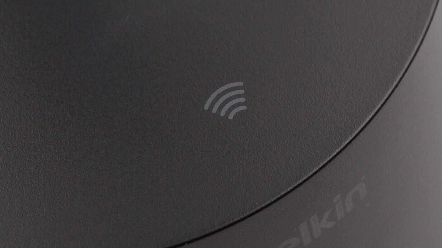
The top of the base is marked with an NFC logo. Simply bringing your phone close enables seamless connection without the need to download any additional apps.
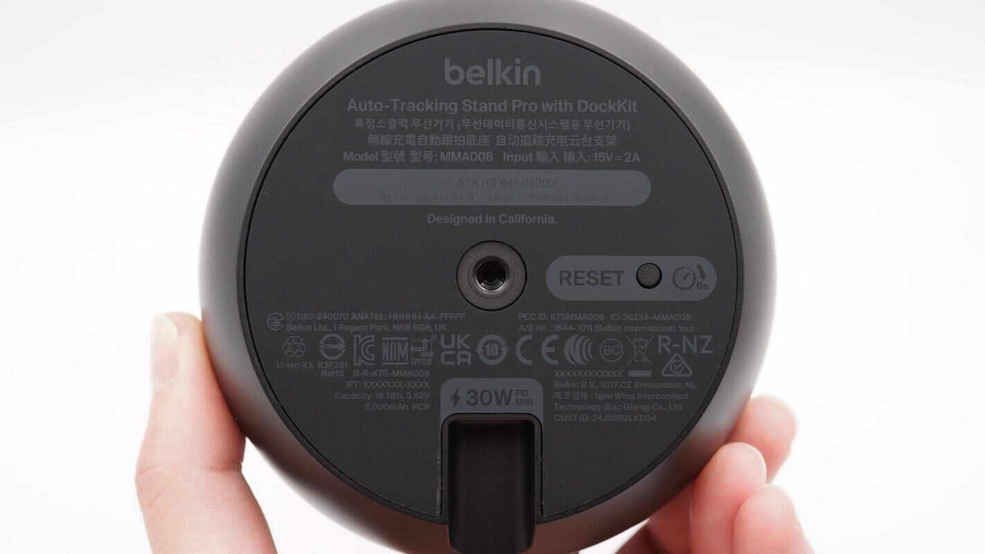
The bottom is equipped with a non-slip pad and printed with the specifications.
Model: MMA008
Input: 15V 2A
The product has passed KC, CE, UKCA, and other certifications.
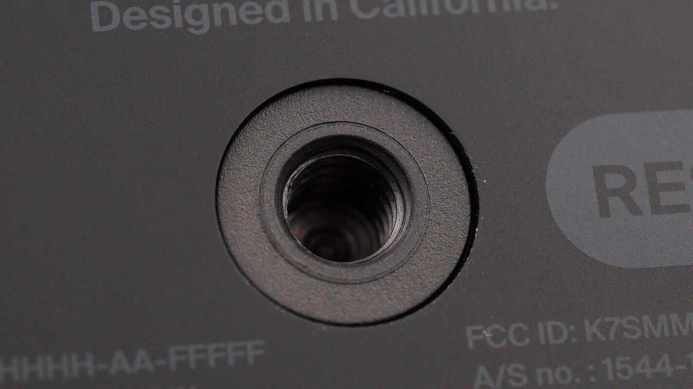
There is a standard 1/4-inch threaded nut at the center of the bottom, allowing it to be used with camera tripods and other mounts.
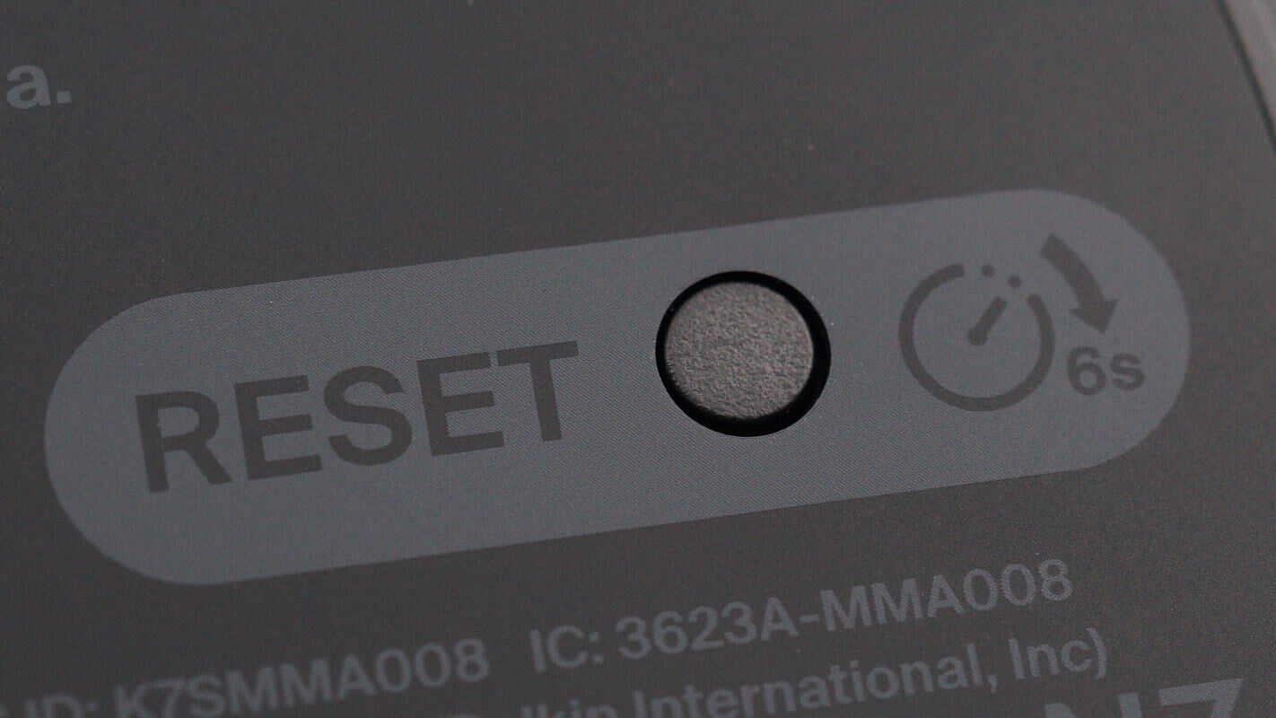
To the right of the threaded nut is a reset button; pressing and holding it for 6 seconds will perform a reset.
The back of the base and the support rod each have a power input port and an indicator light.
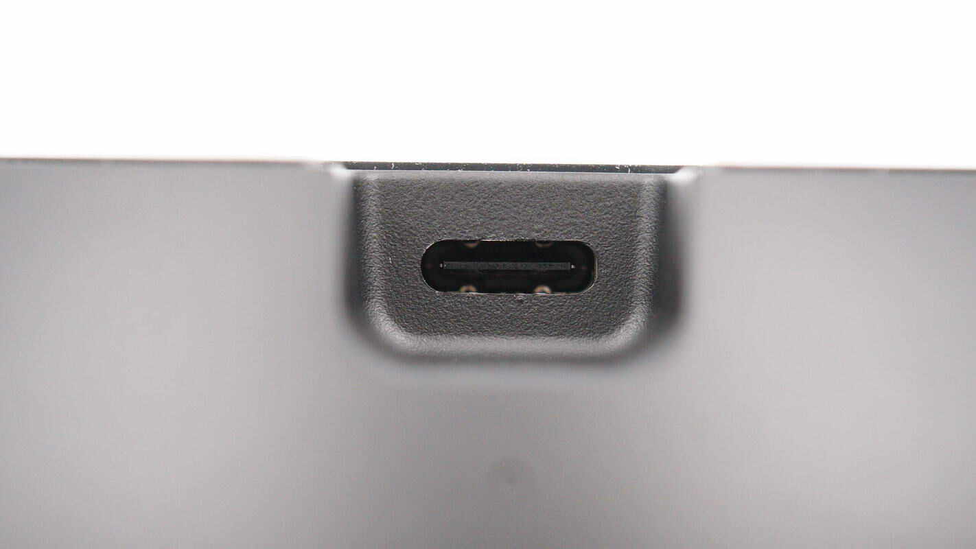
The power input port is a USB-C connector.
Indicator lights are designed on both the front and back of the base, allowing users to monitor the device status whether shooting from the front or rear.
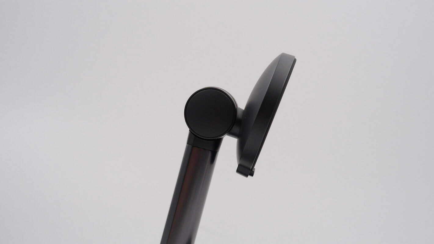
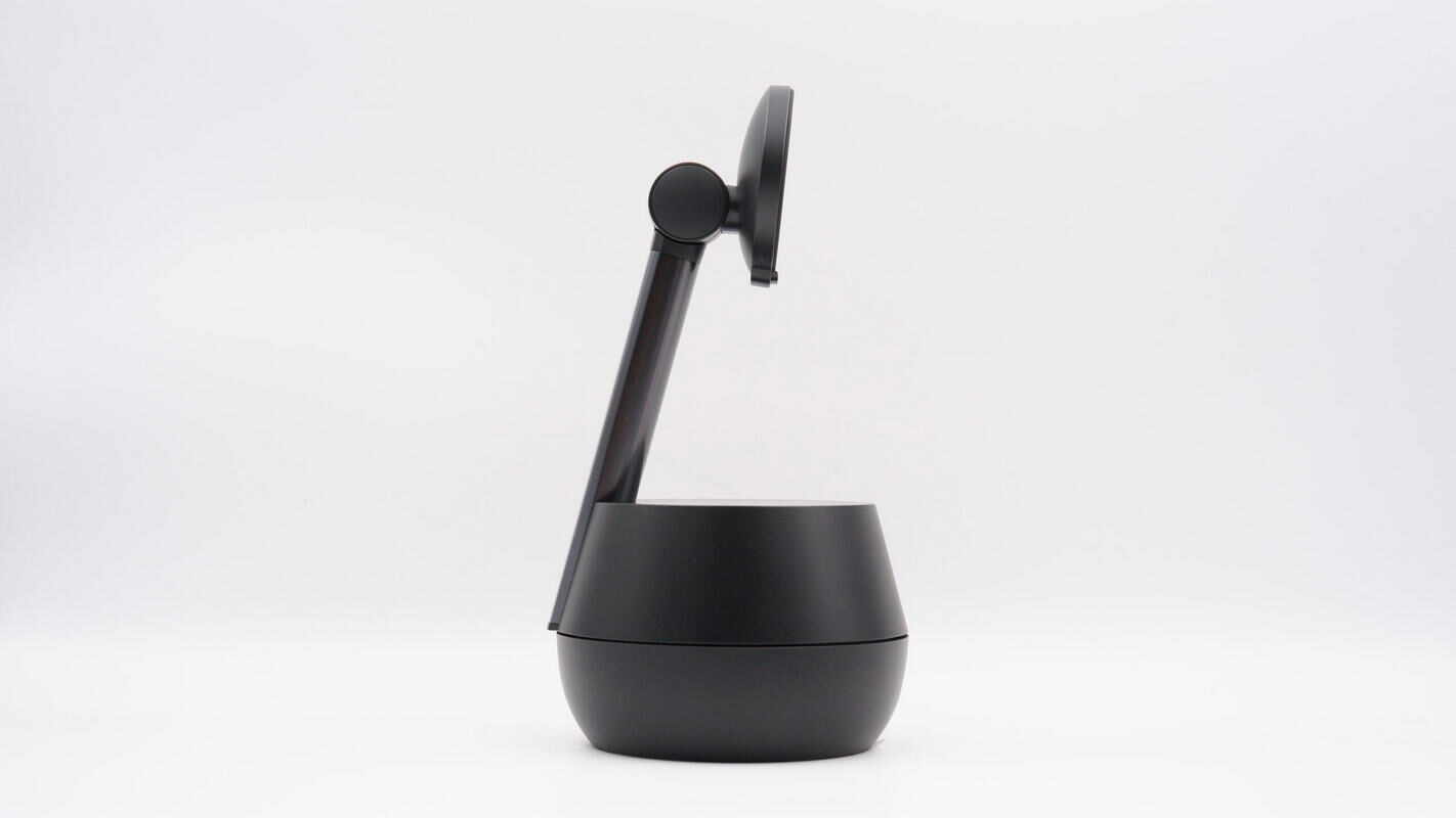
The wireless charging pad and support rod are connected with an adjustable joint.
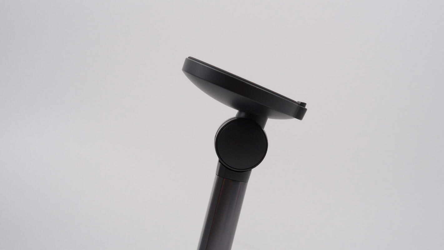
The wireless charging pad supports 90° adjustment.
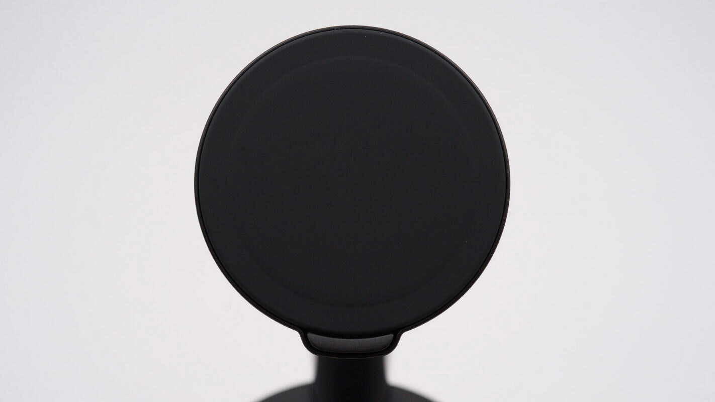
The wireless charging pad features a built-in MagSafe magnetic module, providing a strong 10N magnetic attraction. It delivers 15W wireless charging for iPhones.
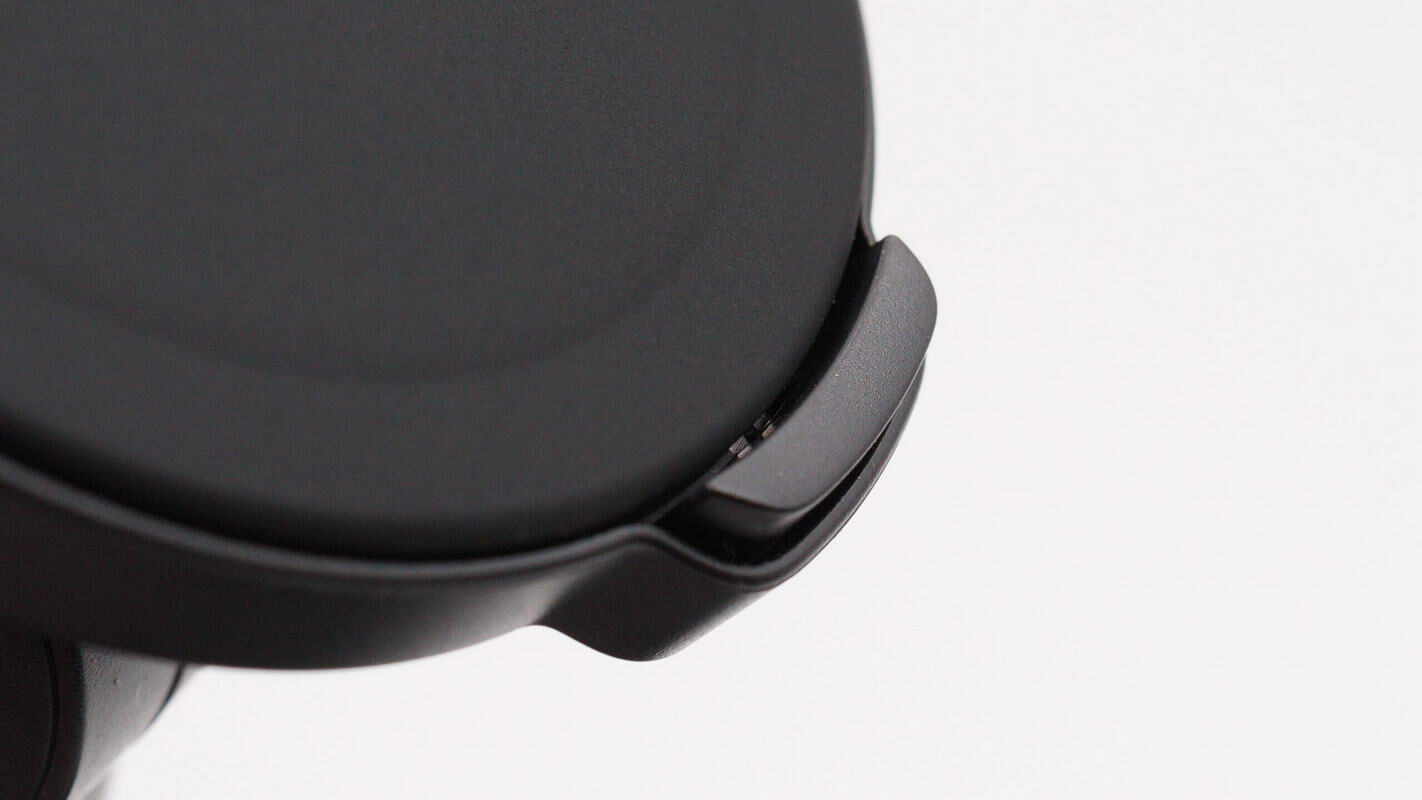
There is a touch-sensitive button located beneath the charging pad.
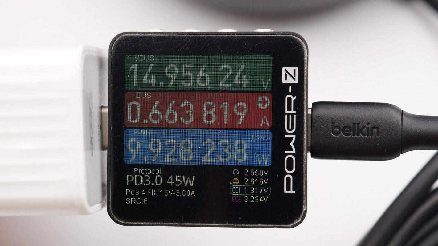
When supplying power to the charging stand, the measured charger output power is about 9.93W.
Teardown
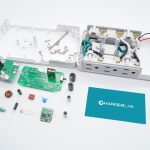
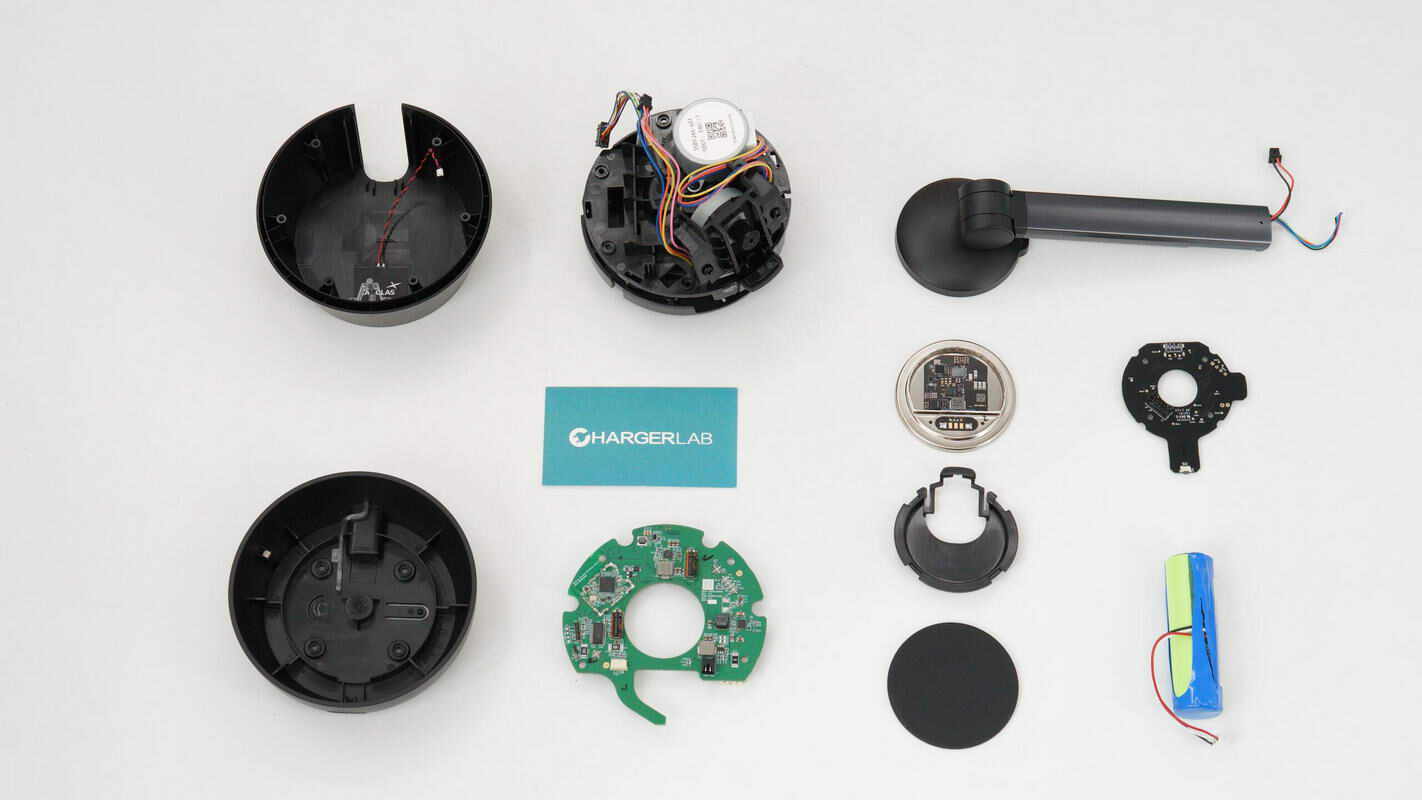
Next, let's take it apart to see its internal components and structure.
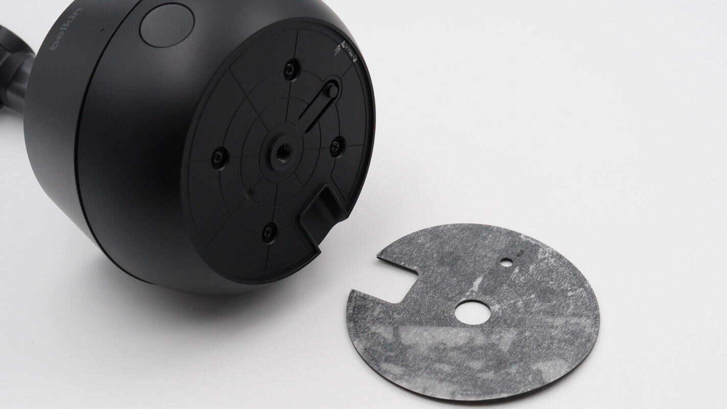
Peel off the non-slip pad. The fixing screws are located at the bottom.
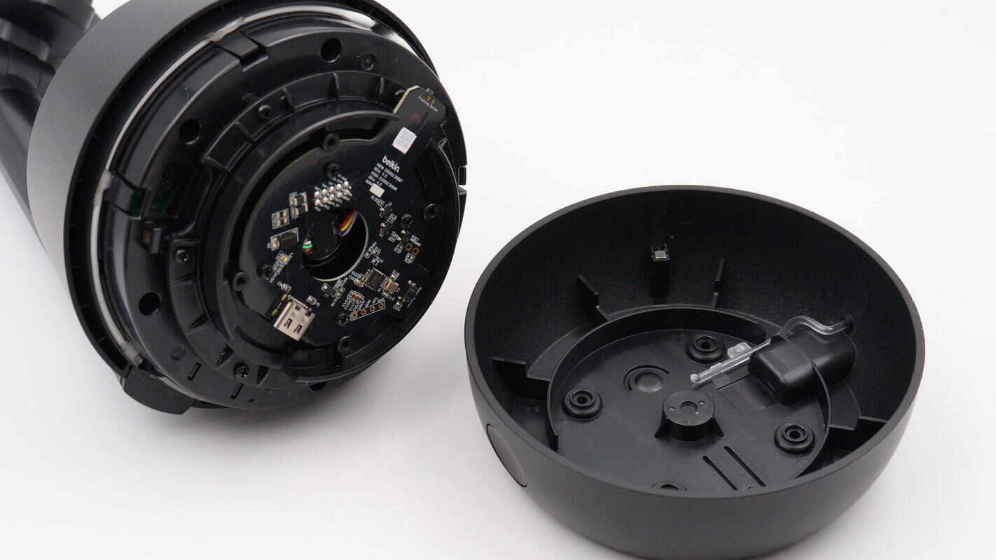
Remove the screws and take off the bottom casing.
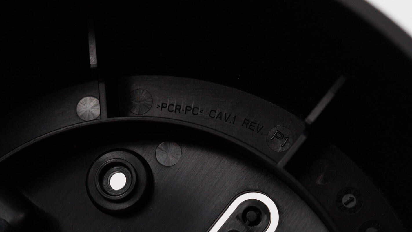
The bottom casing is made of PCR-PC material, consisting of 72% post-consumer recycled (PCR) plastic, which is recyclable and also fire-resistant.
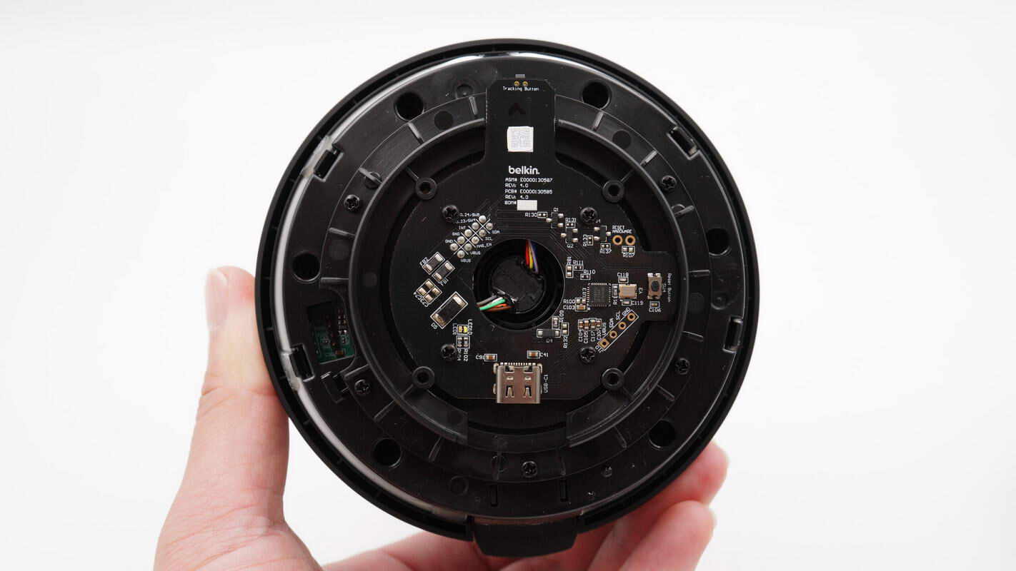
The black PCB at the bottom is secured with screws.
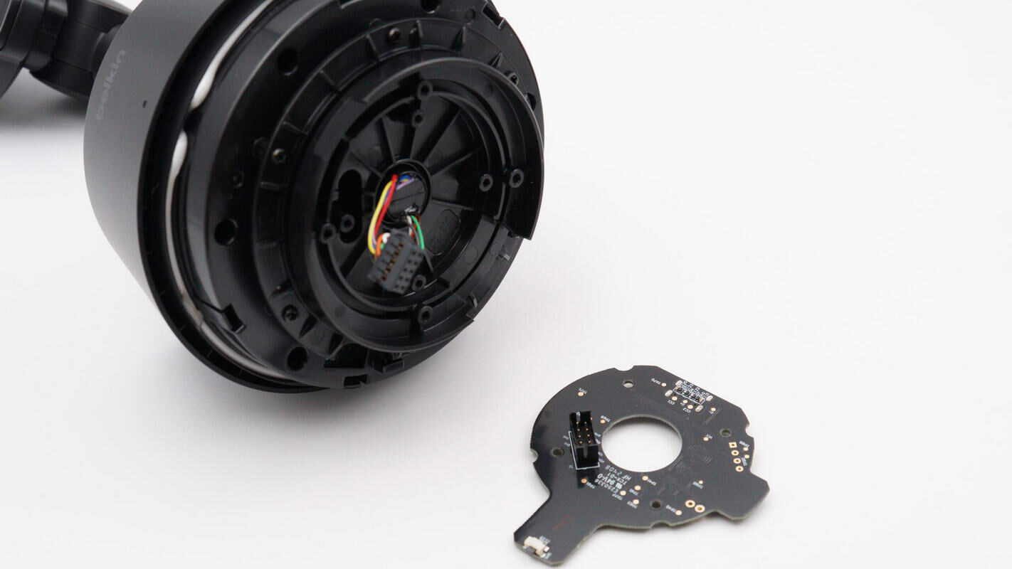
Remove the black PCB. On the other side, there is a connector slot for the slip ring wires.
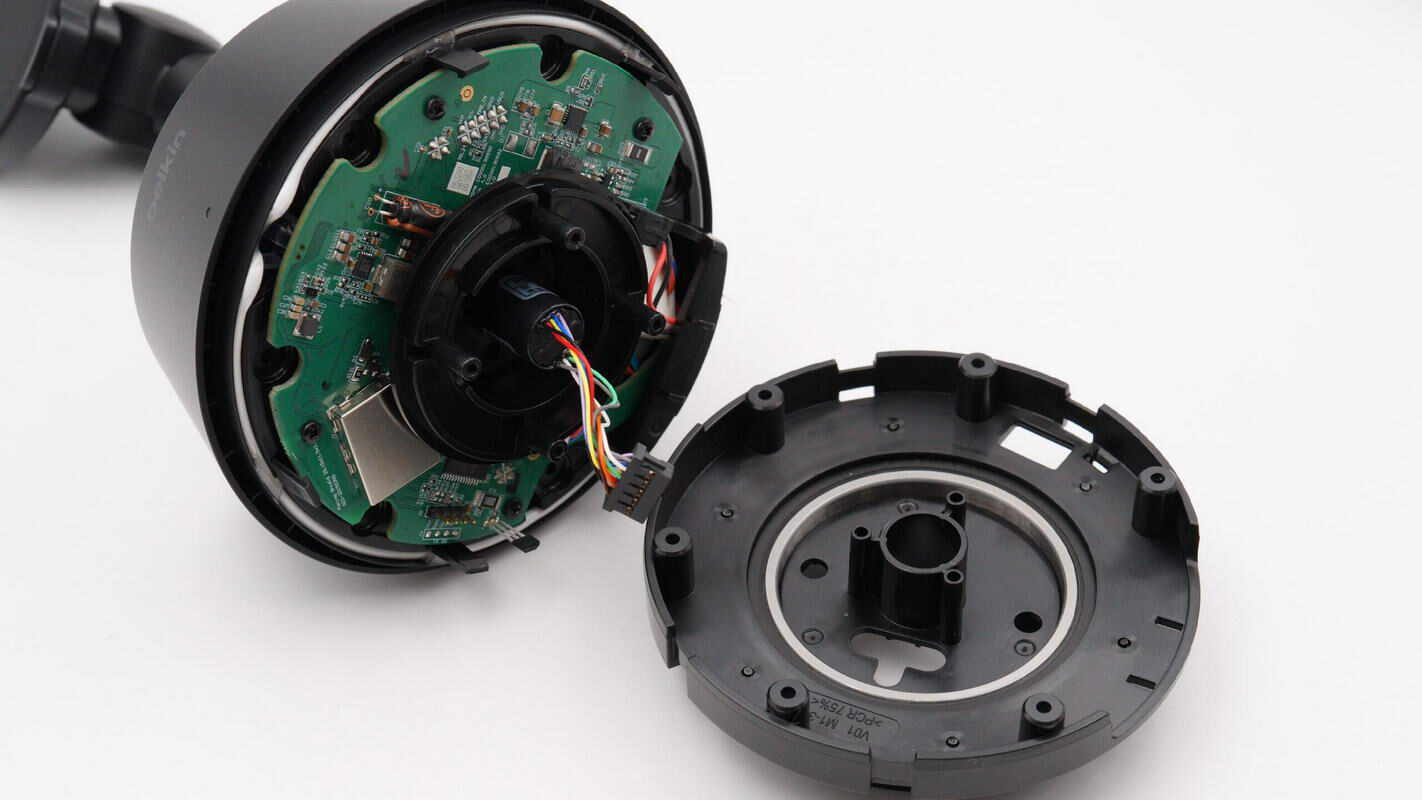
After removing the inner plastic casing, a green PCB is revealed inside.
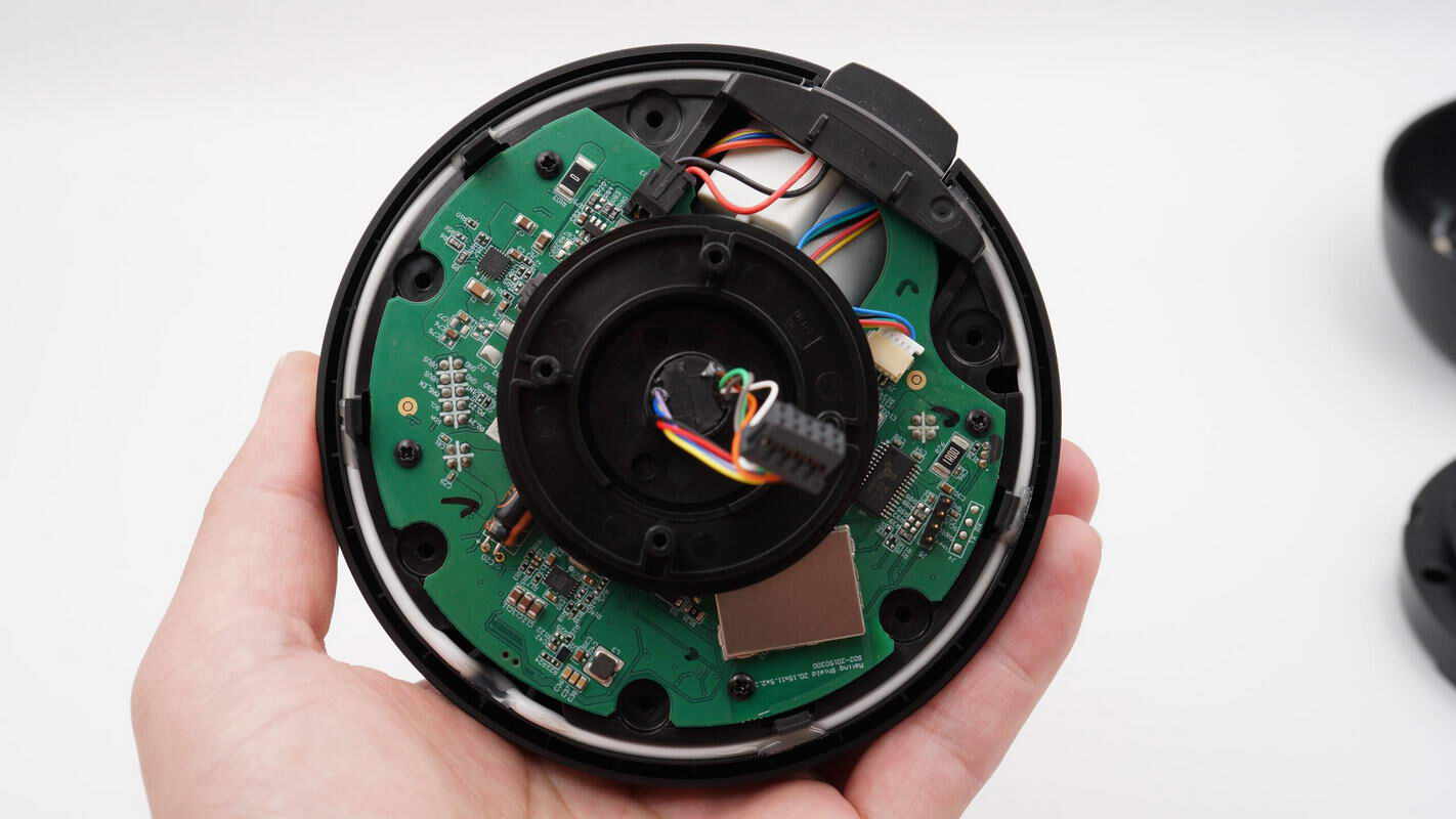
The PCB is secured with screws, and a white sealing ring is positioned along the edge of the module.
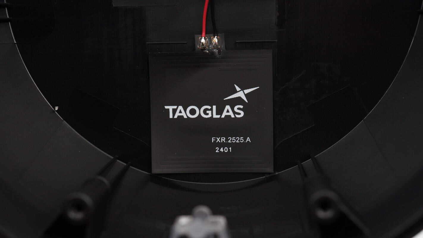
Remove the top cover of the base to reveal a close-up view of the internal NFC antenna.
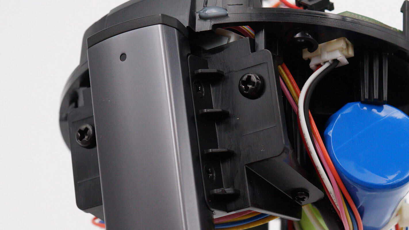
The module is connected to the support rod using screws.
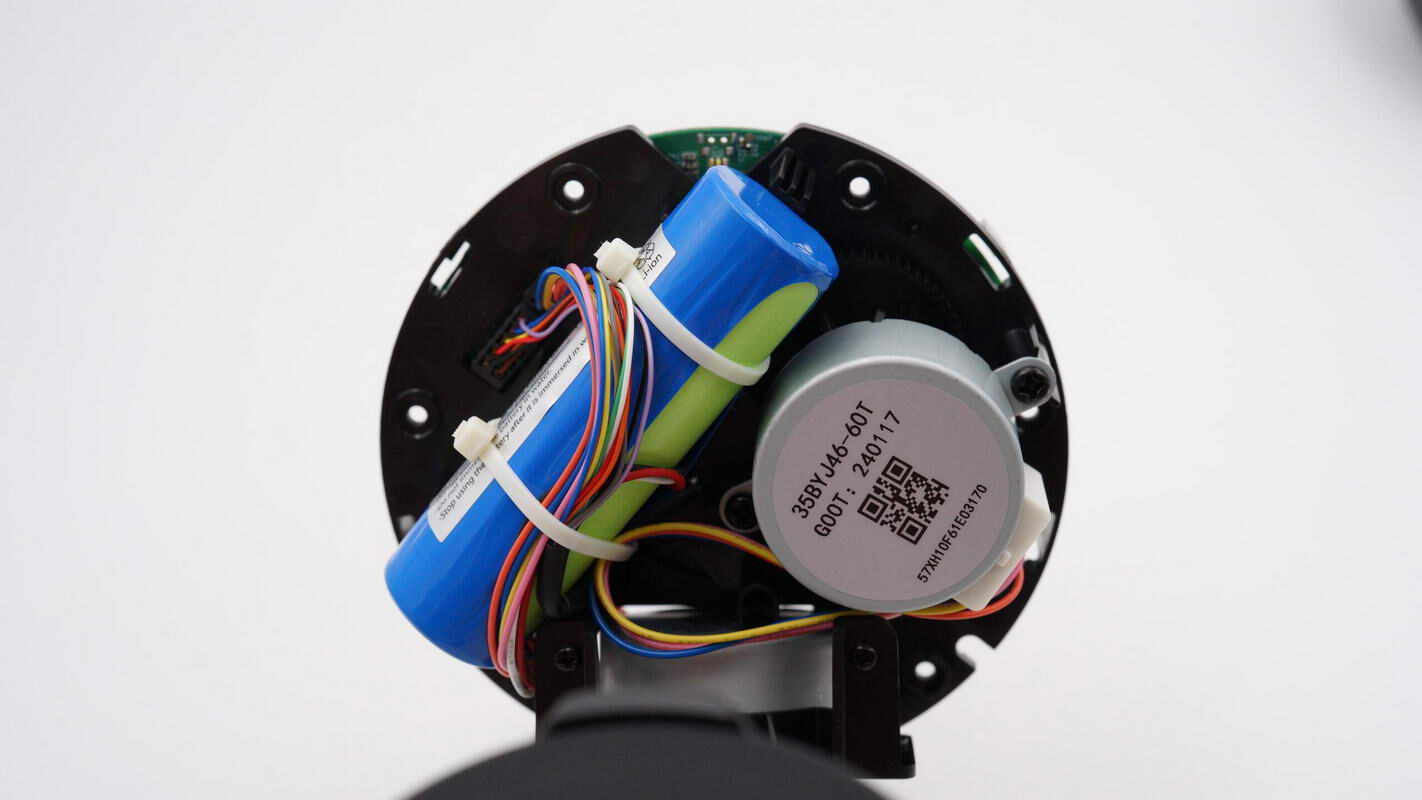
At the top of the module, there is a battery and a motor. The motor is secured with screws, while the battery is fastened with two zip ties.
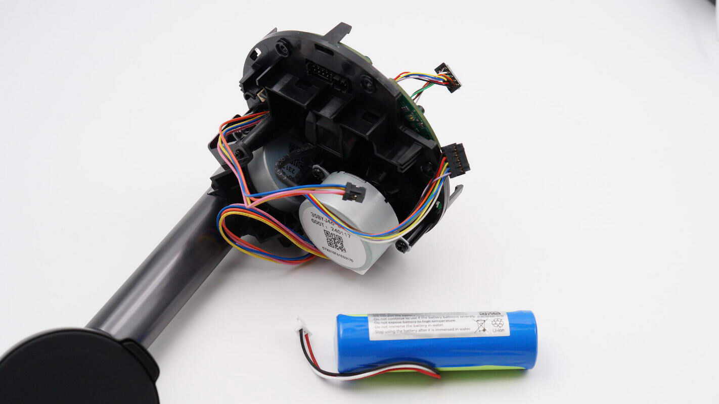
Remove the battery.
Remove the slip ring located at the center of the base.
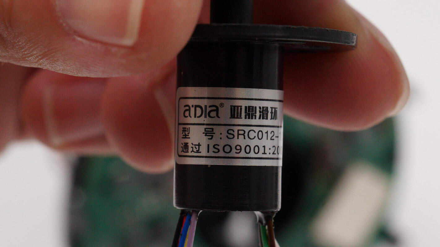
Close-up view of the SRCO12 series miniature cap-type slip ring.
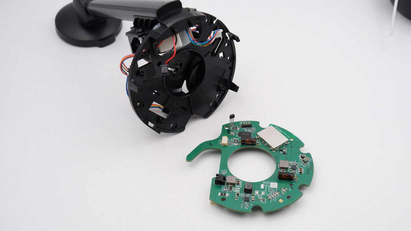
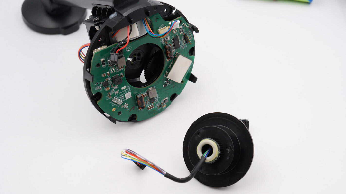
Remove the green PCB as well. The motor, MagSafe wireless charging module, and other components are connected to the green PCB via plug-in wire connectors.
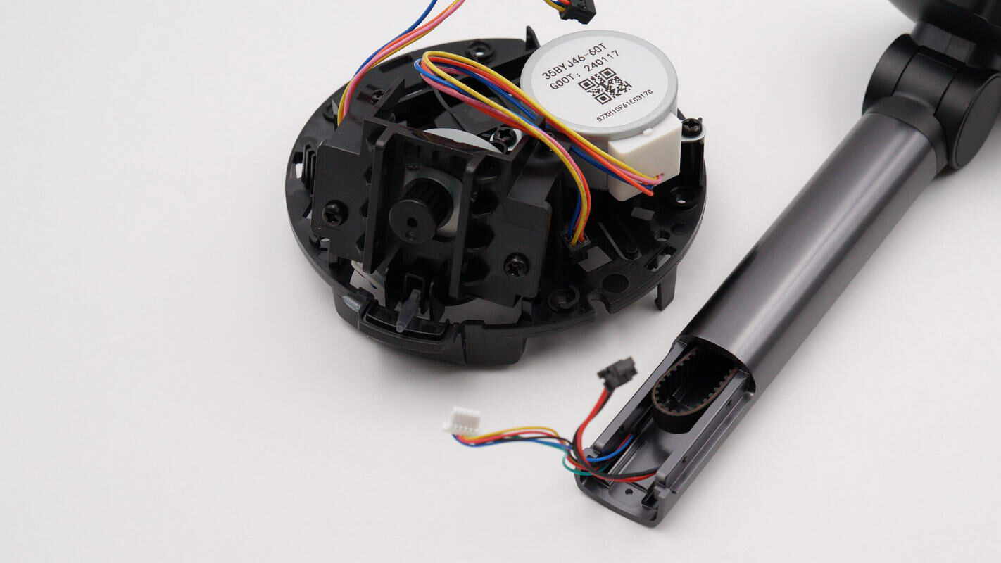
Separate the bottom module from the support rod. The module contains two motors that independently control rotation in the horizontal and vertical directions.
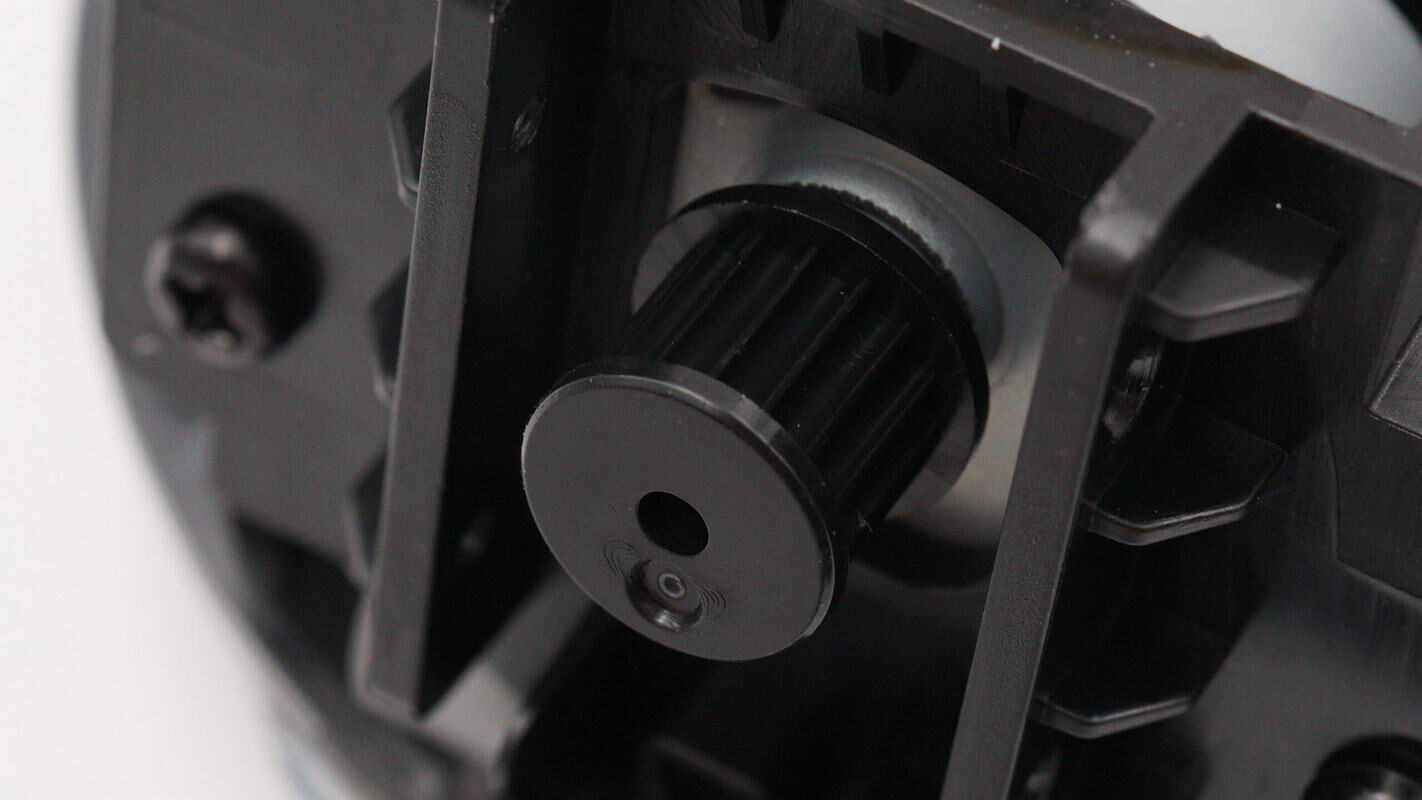
Close-up of the vertical control motor shaft.
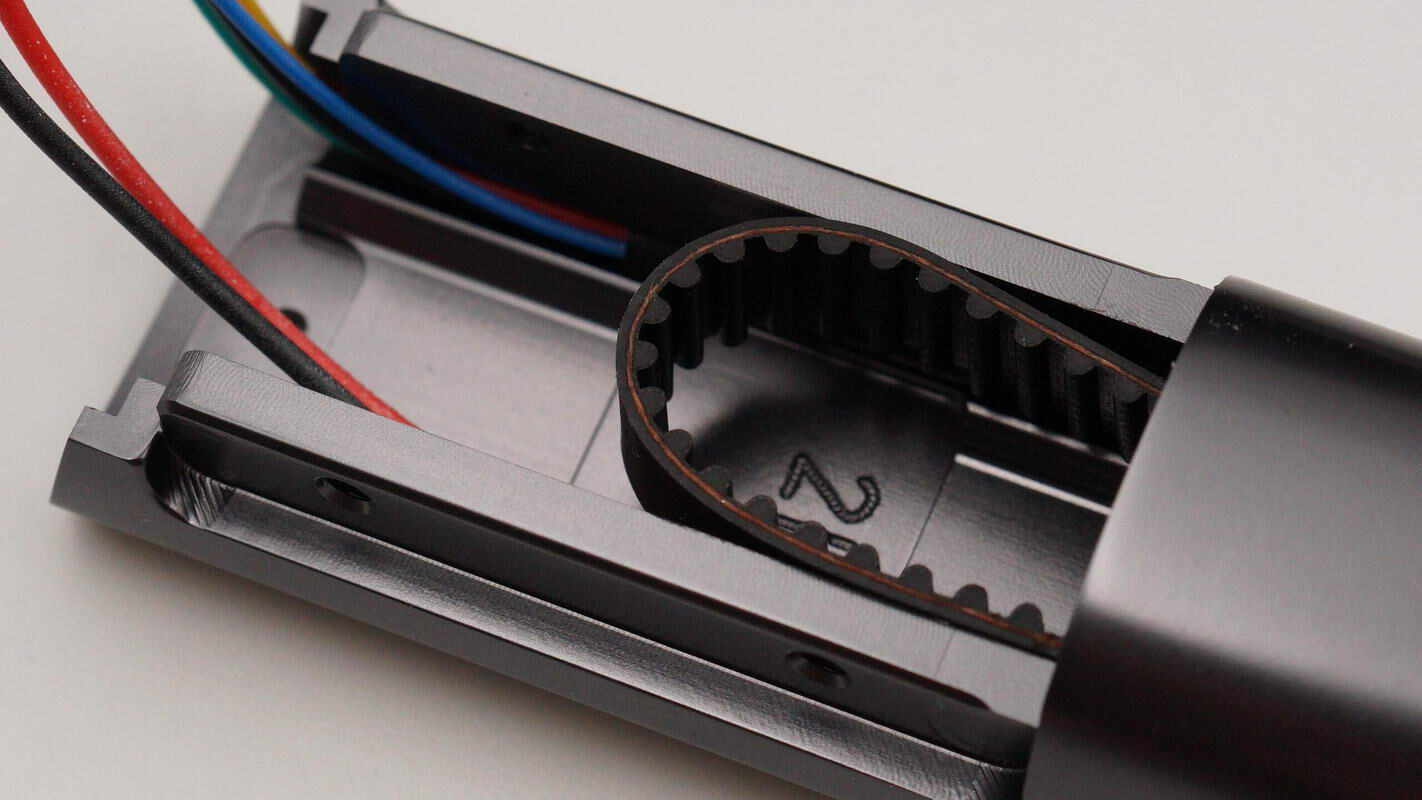
Close-up of the timing belt inside the support rod.
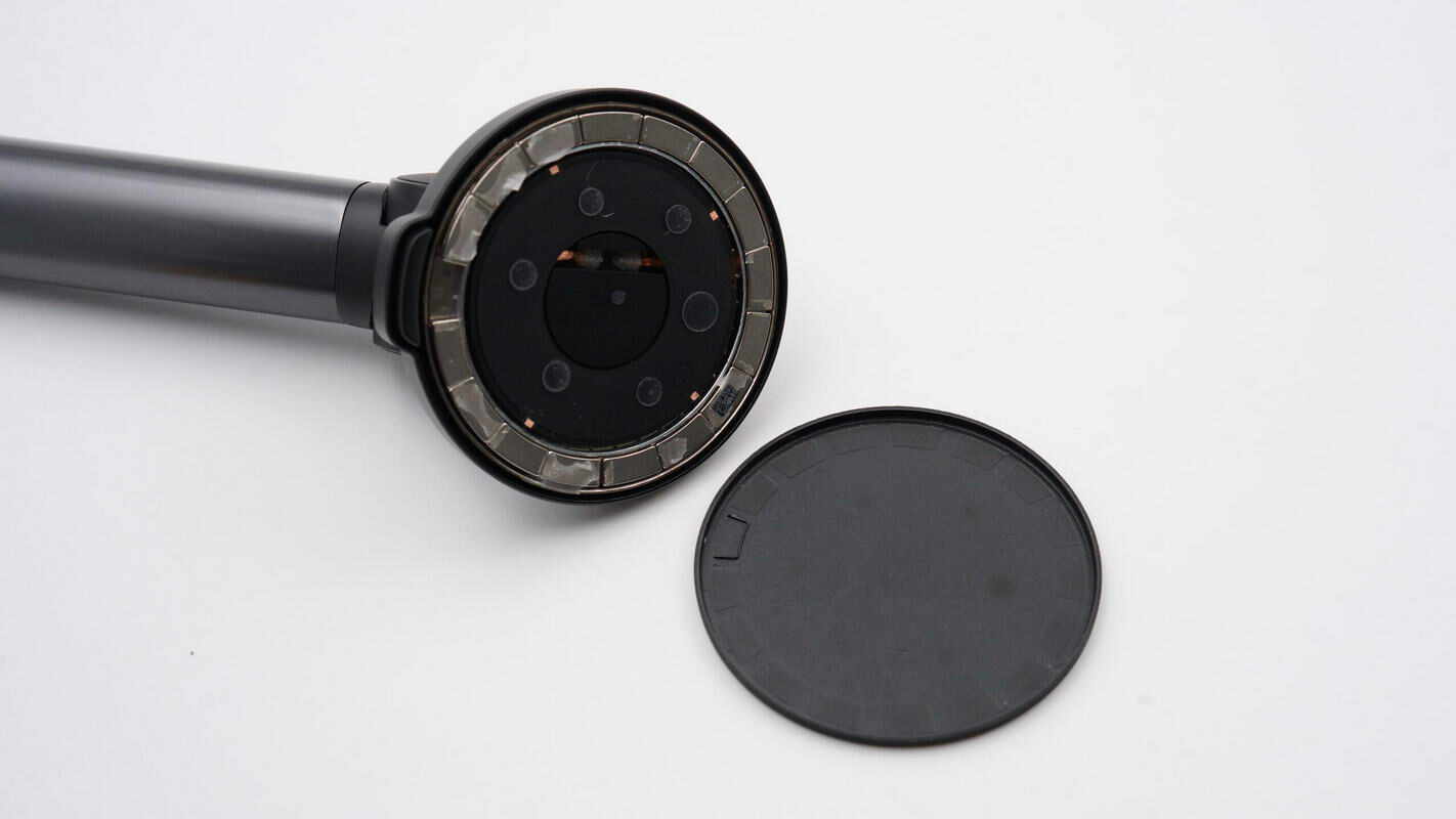
Remove the front plastic cover of the wireless charging pad.
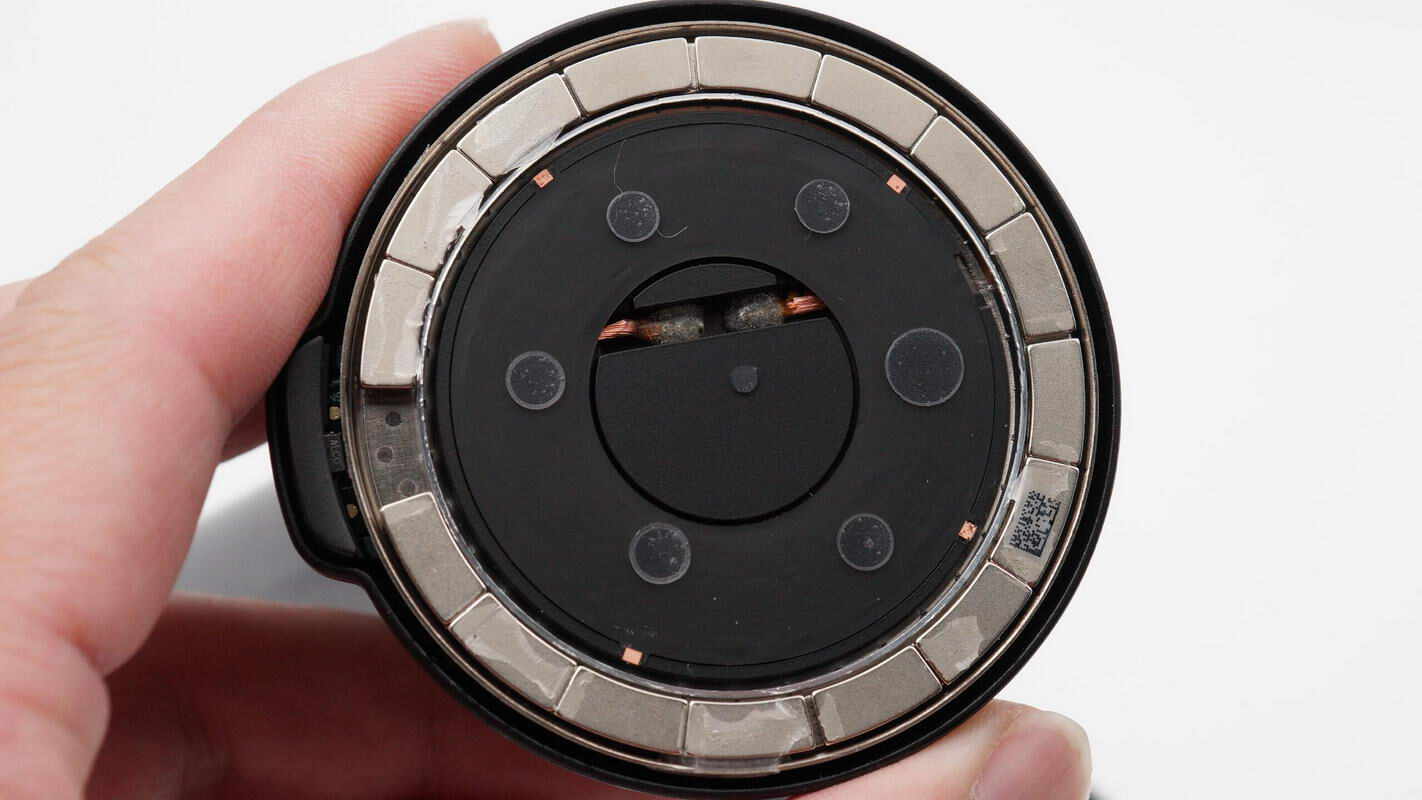
The magnetic ring is composed of 16 curved small magnets.
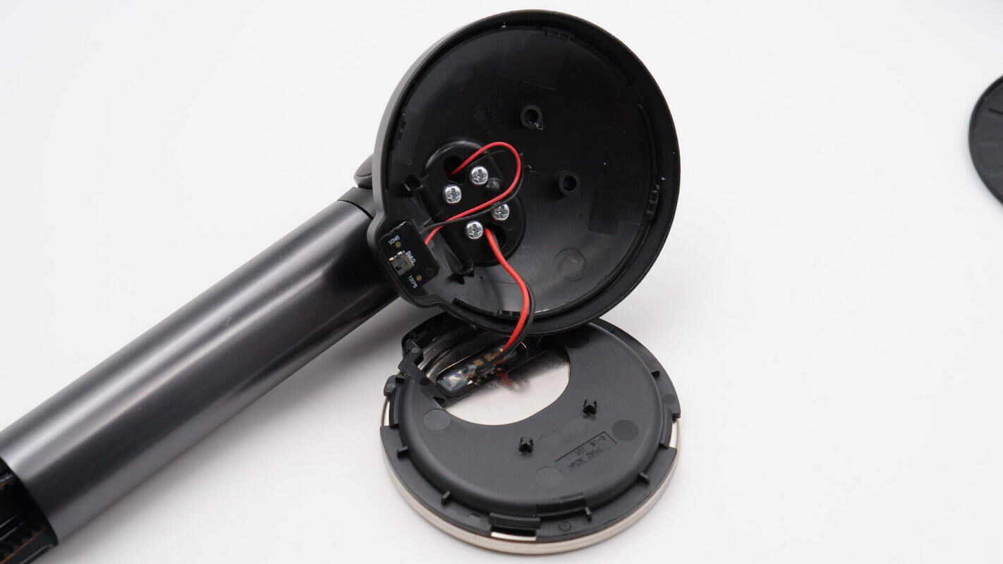
Remove the magnetic charging module.
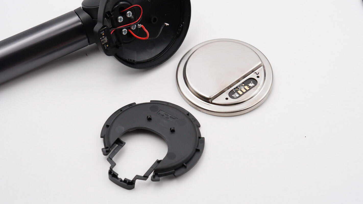
Separate the charging stand from the magnetic charging module.
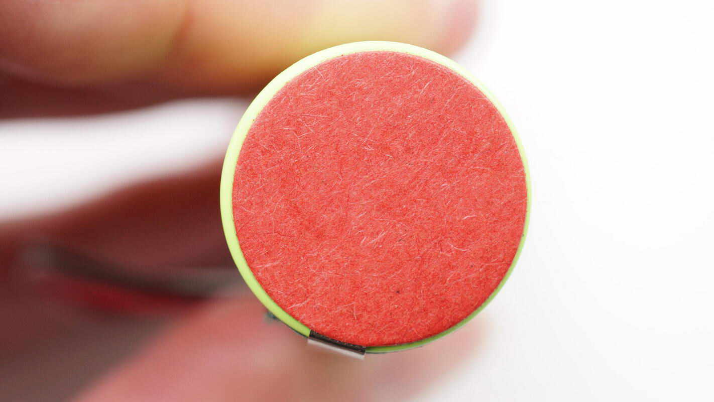
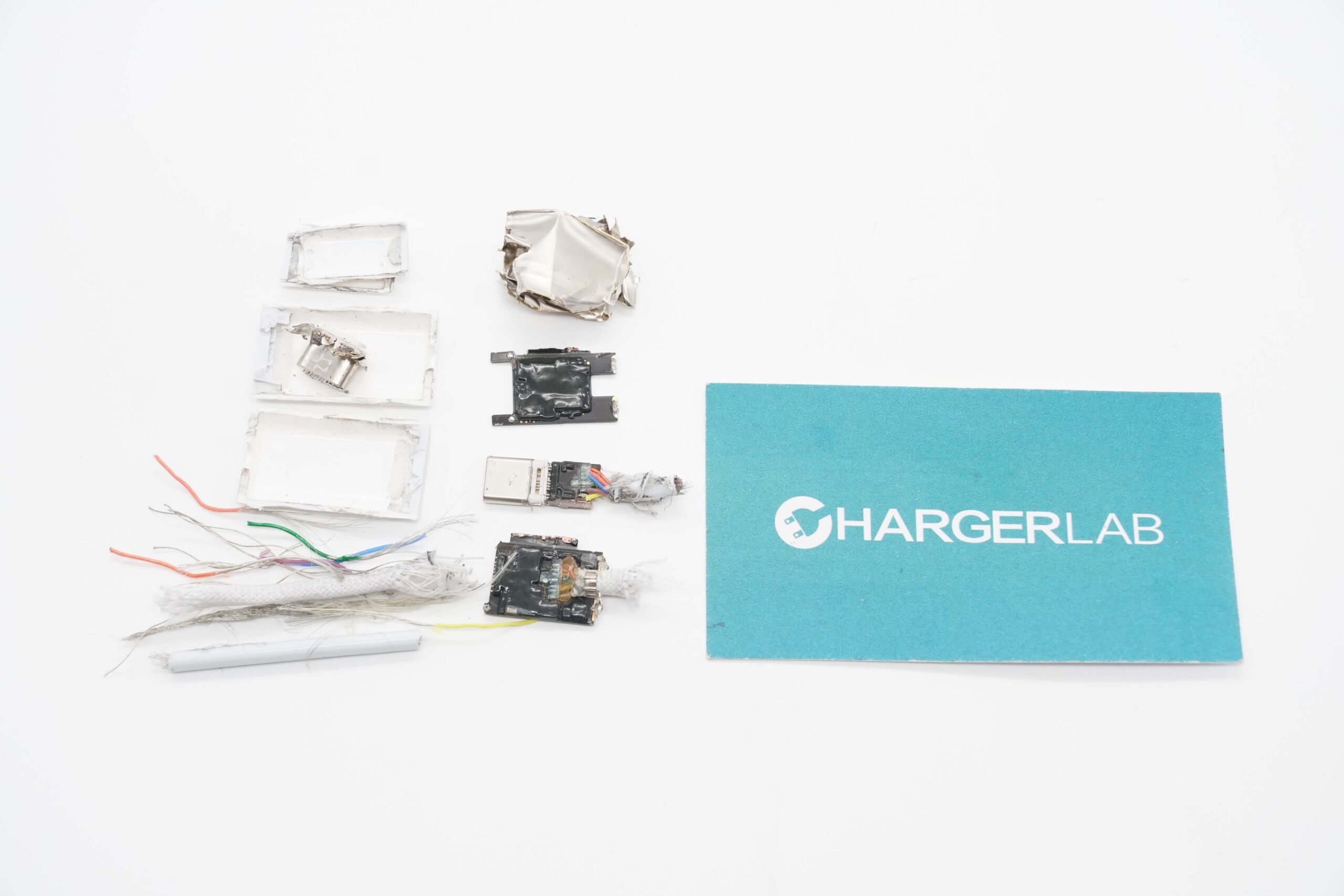
Insulating paper is attached to both ends of the battery.
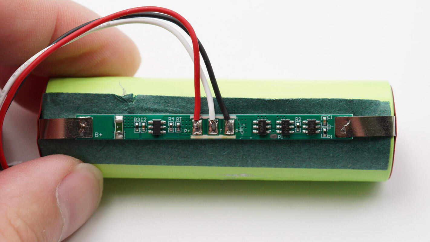
The battery is spot-welded to a lithium battery protection PCB via nickel tabs, with rice paper insulation between them. The PCB includes a lithium battery protection chip and two battery protection MOSFETs.
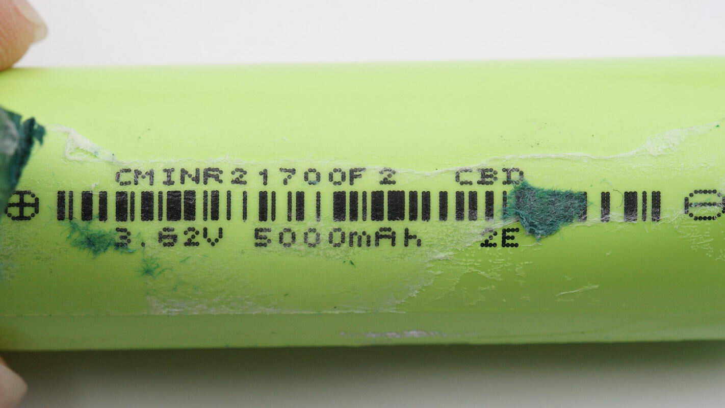
The battery model is CMINR21700F 2, with a nominal voltage of 3.62V and a capacity of 5000mAh.
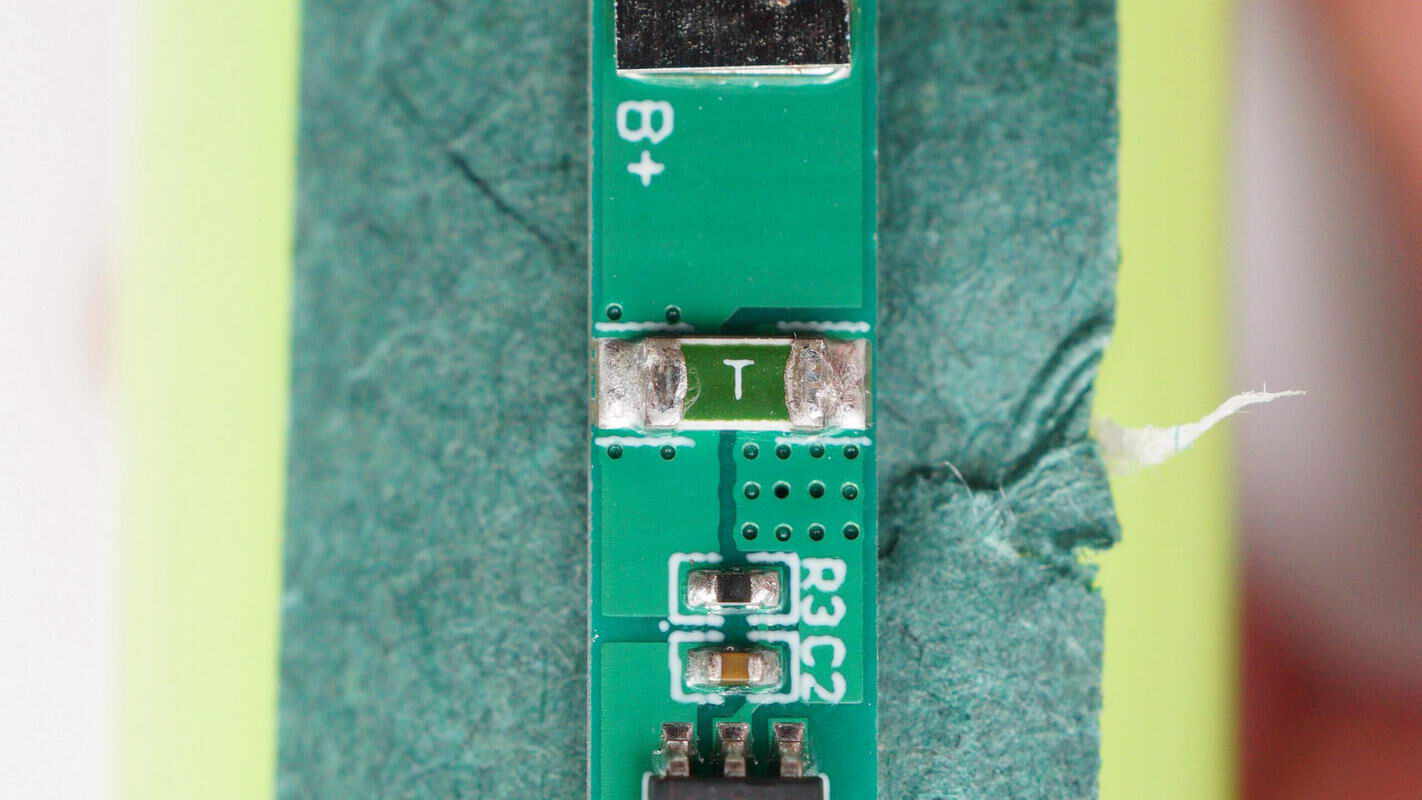
Close-up of the green SMD fuse.
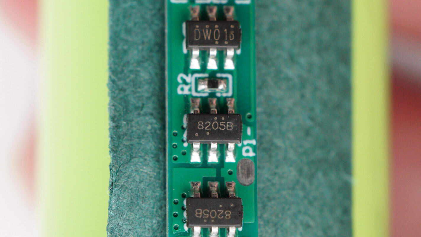
Close-up of the lithium battery protection chip marked with DW01 and two 8205B battery protection MOSFETs.
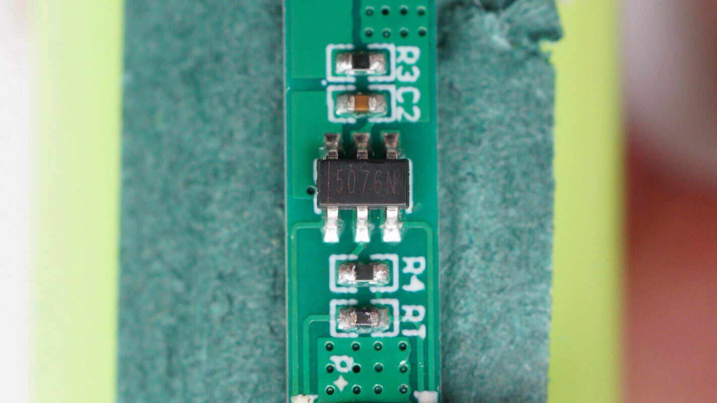
Close-up of a chip marked with 5076N.
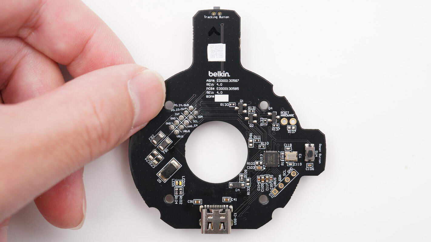
The front side of the black PCB features a USB-C socket, a protocol chip, a crystal oscillator, and a reset button.
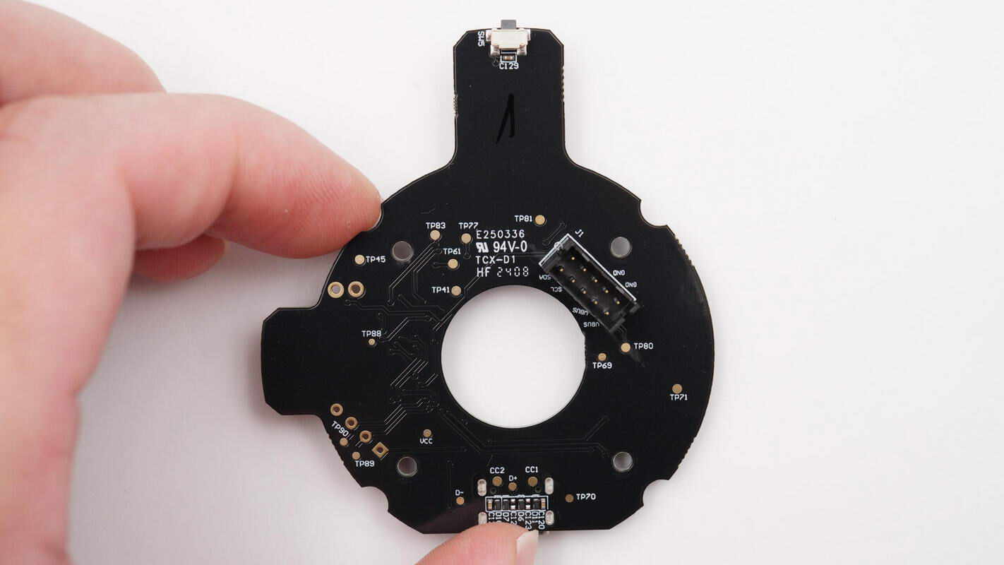
The other side is equipped with the auto-tracking start/stop button and the slip ring connector slot.
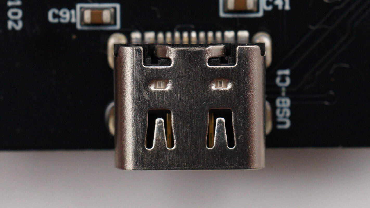
Close-up of the USB-C socket.
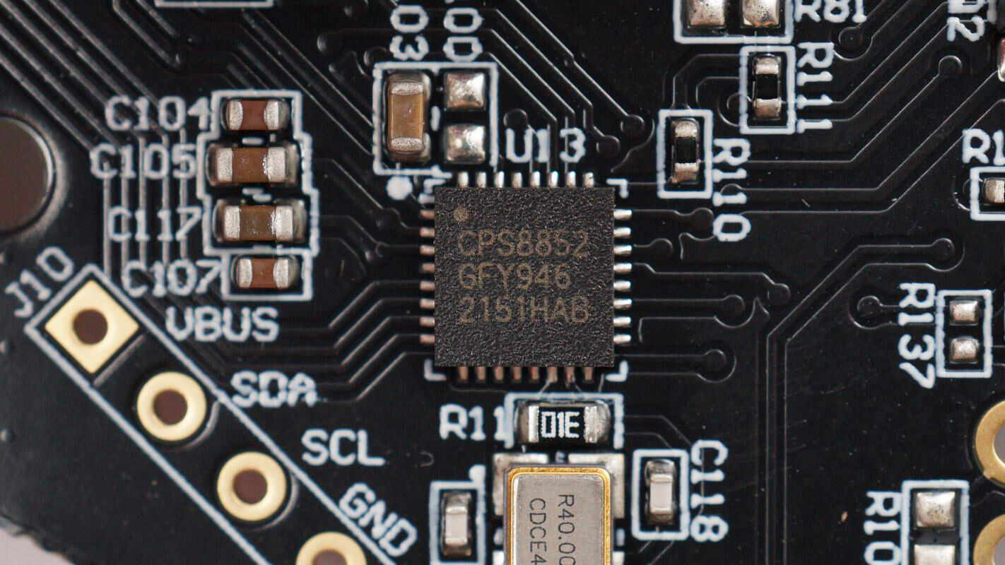
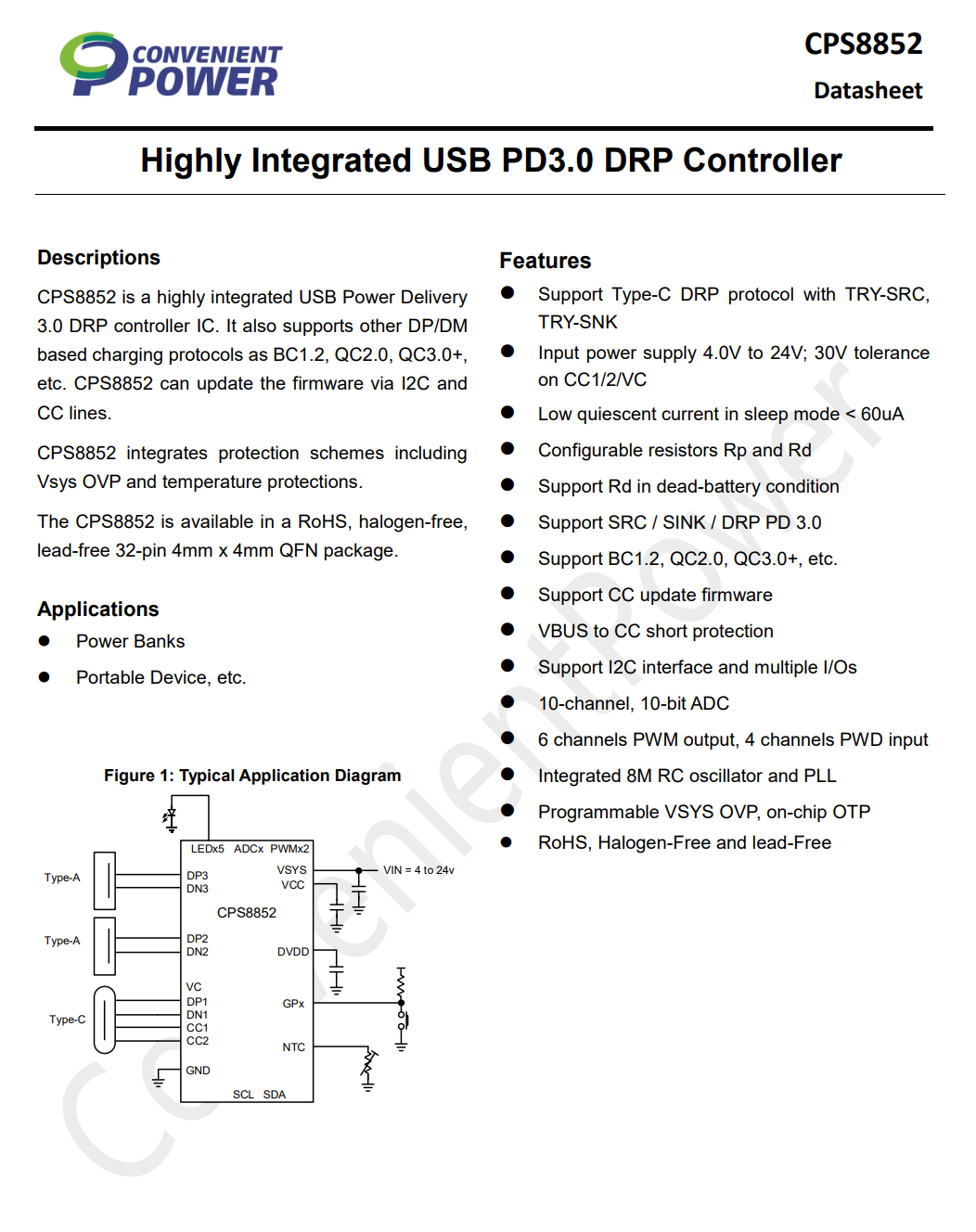
The protocol chip is from CPS, model CPS8852. It is a highly integrated PD 3.0 protocol chip that supports DP/DM-based fast charging protocols such as BC1.2, QC2.0, and QC3.0. The CPS8852 can update its firmware via I2C and CC interfaces. It features a 32-bit ARM core with 48KB of FLASH memory and 8KB of SRAM.
The chip includes a built-in 10-channel, 10-bit ADC for voltage and current detection, six PWM signal outputs, and an internal RC oscillator. Additional protections include programmable system over-voltage protection and internal thermal shutdown. Both the CC and VC pins support up to 30V withstand voltage. The chip comes in a QFN-32 package.
Here is the information about CPS CPS8852.
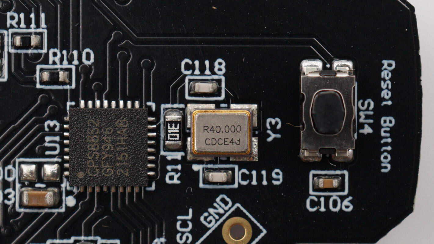
Close-up of the 40.000 MHz clock crystal oscillator.
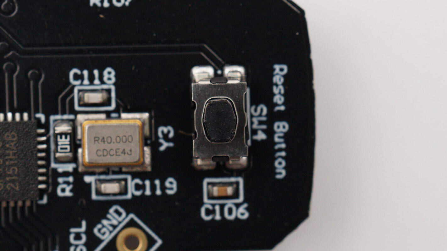
Close-up of the reset button.
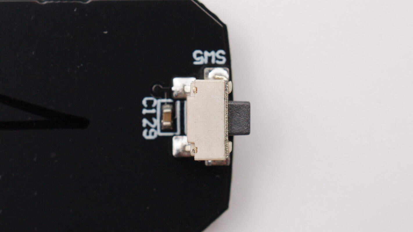
Close-up of the auto-tracking start/stop button.
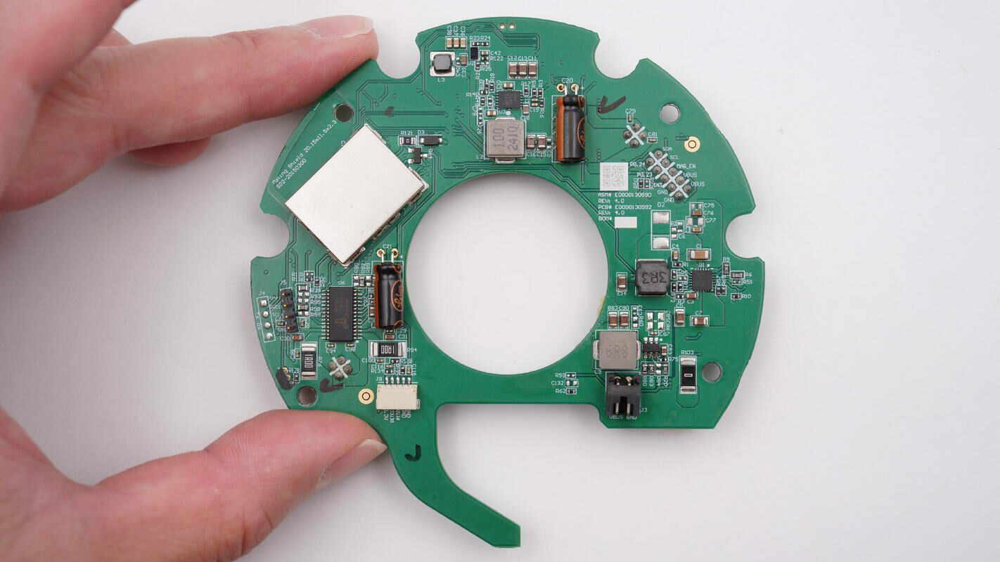
The front side of the green PCB features a motor driver chip, a synchronous boost converter, filtering capacitors, inductors, and other components. A shielding cover is located in the left section.
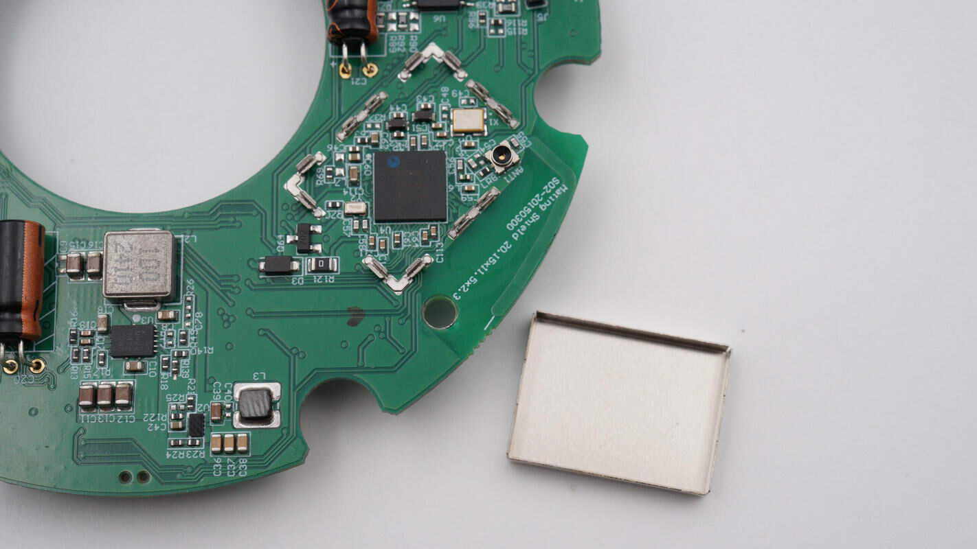
Remove the shielding cover to reveal a Bluetooth SoC.
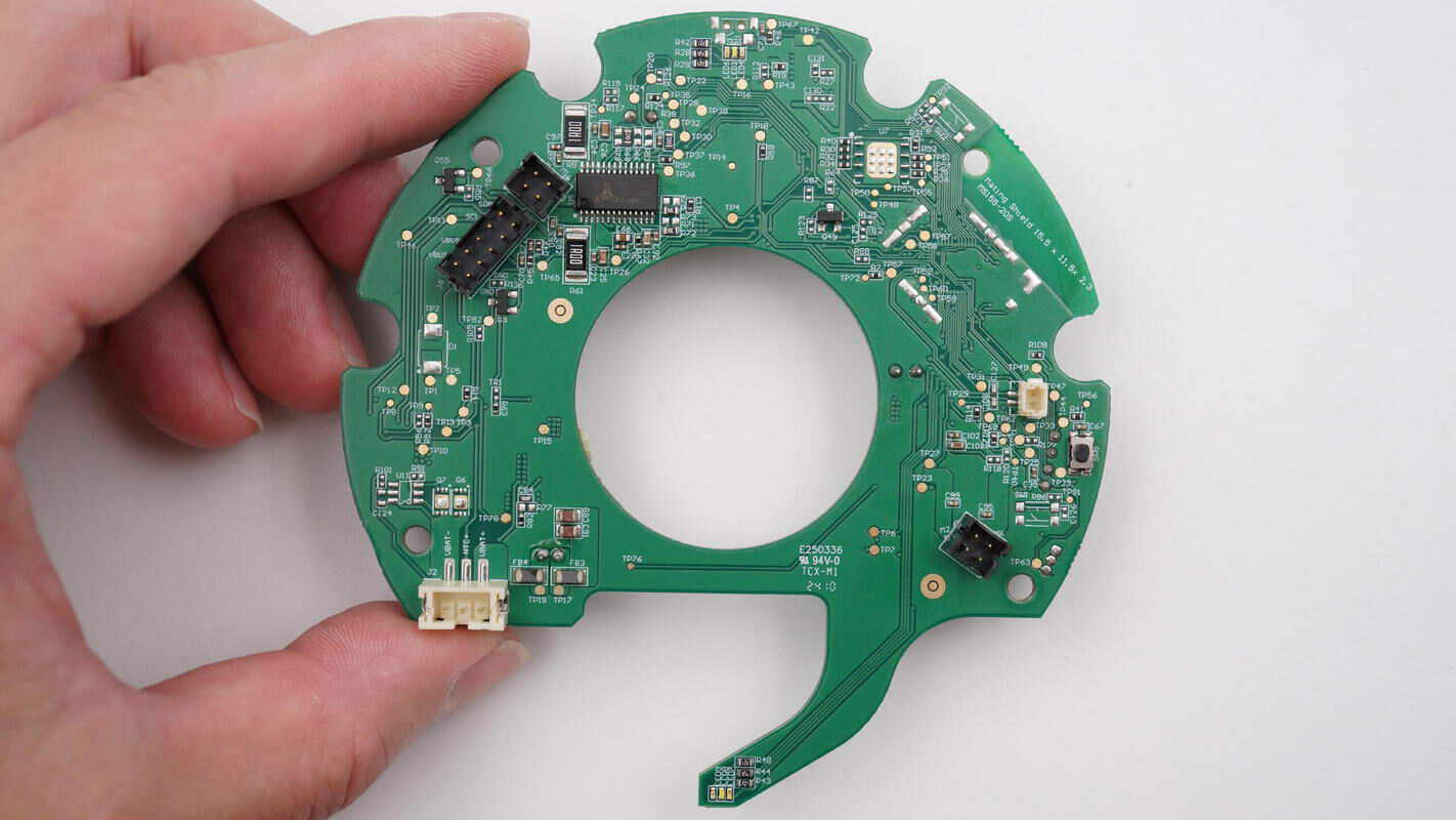
The other side features another motor driver chip along with multiple connector slots.
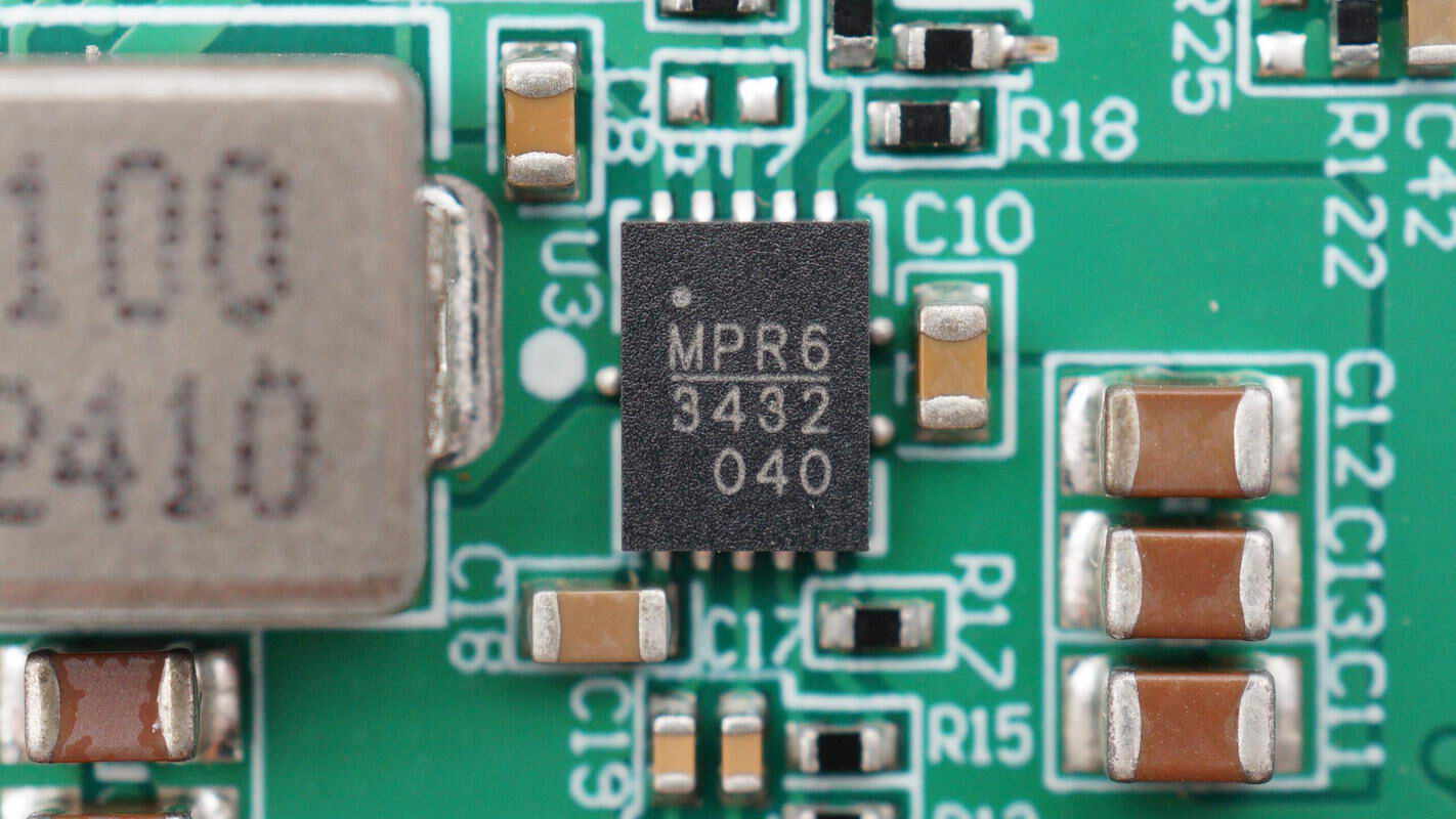
The MPS MP3432 is a 600kHz fixed-frequency, wide input range, highly integrated boost converter. It can start up with input voltages as low as 2.7V and, with its integrated low RDS(ON) power MOSFET, supports output power up to 30W from a single-cell battery. It comes in a QFN-13 (3mm x 4mm) package.
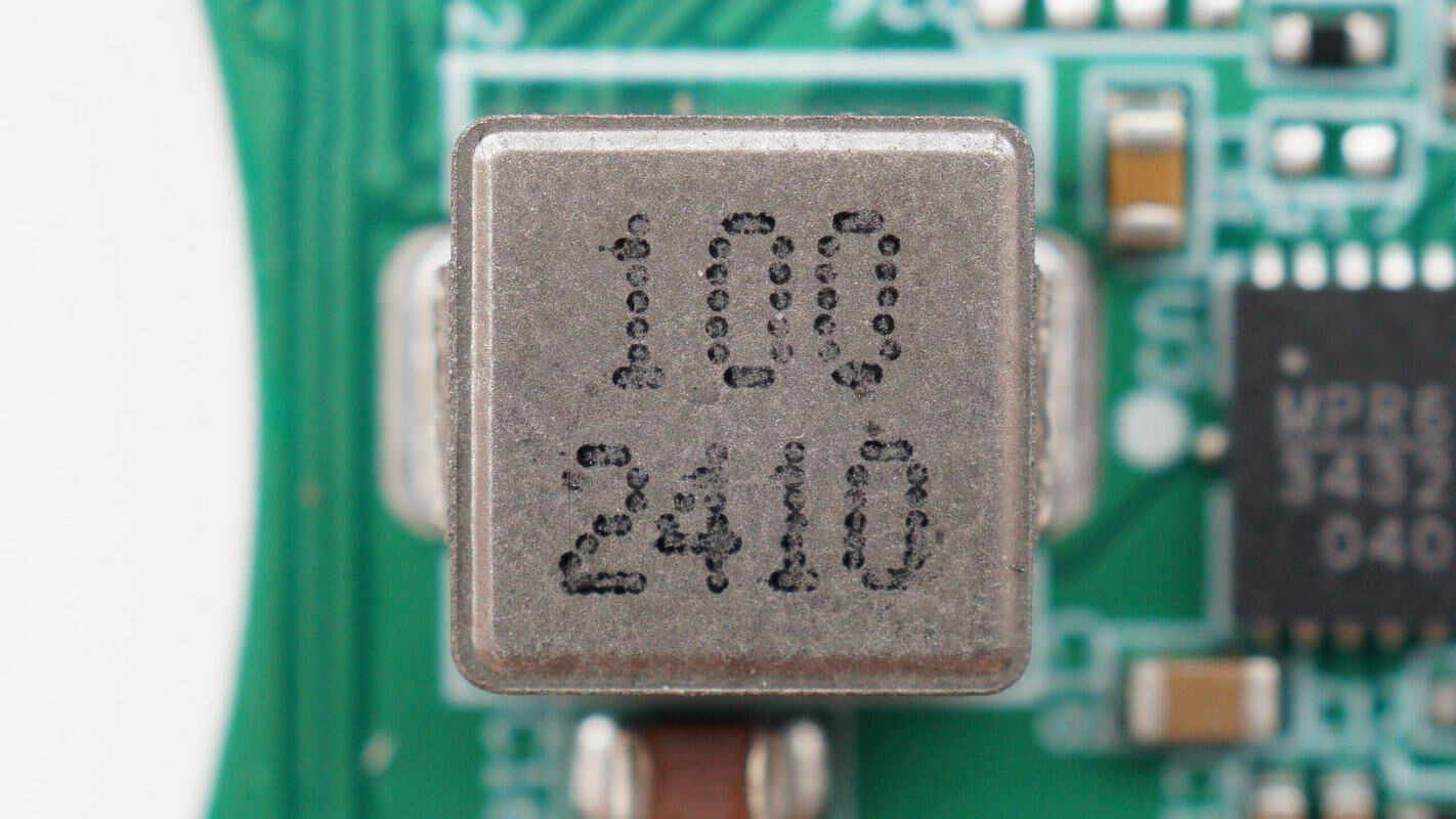
Close-up of the 10μH boost inductor.
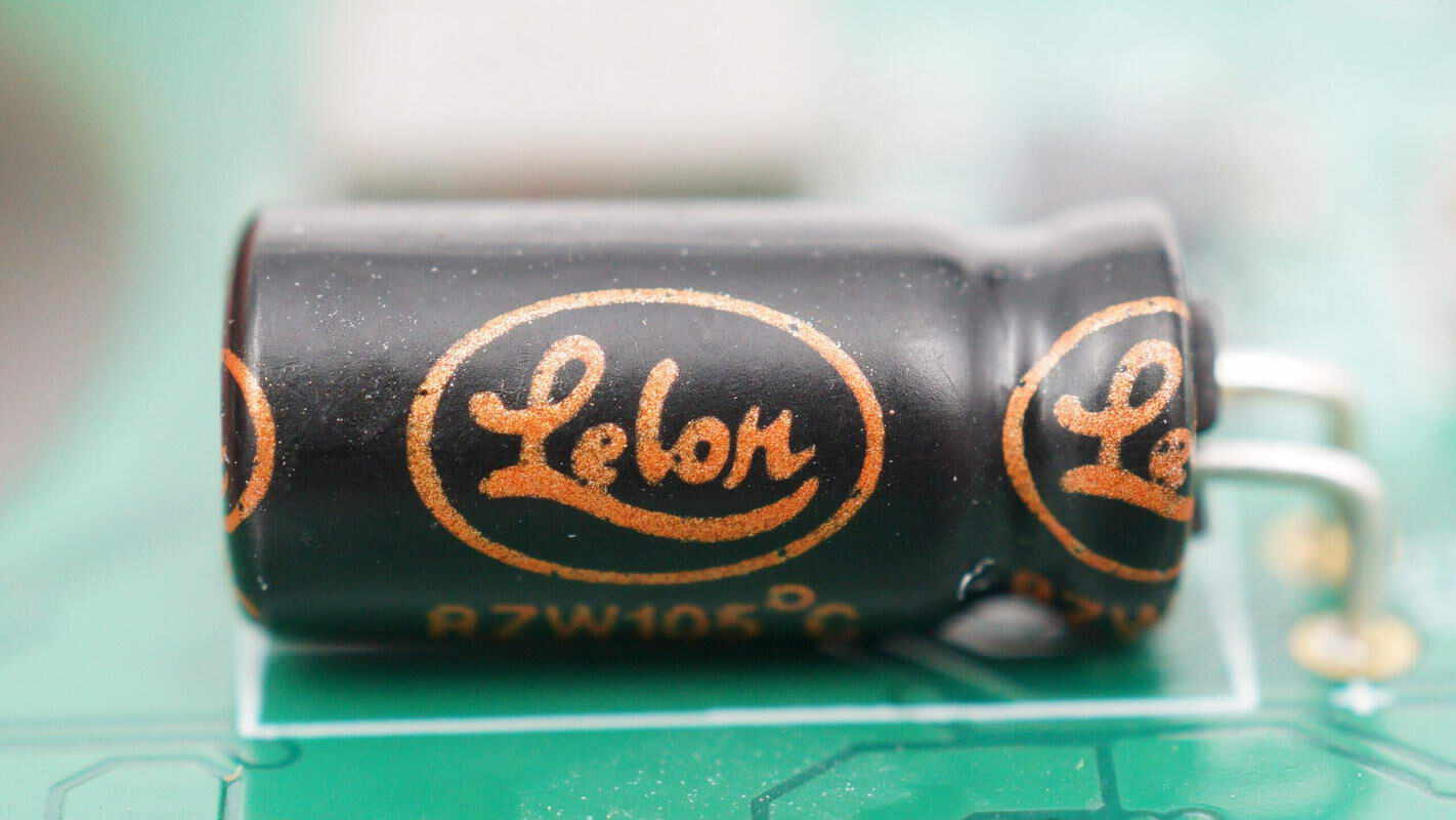
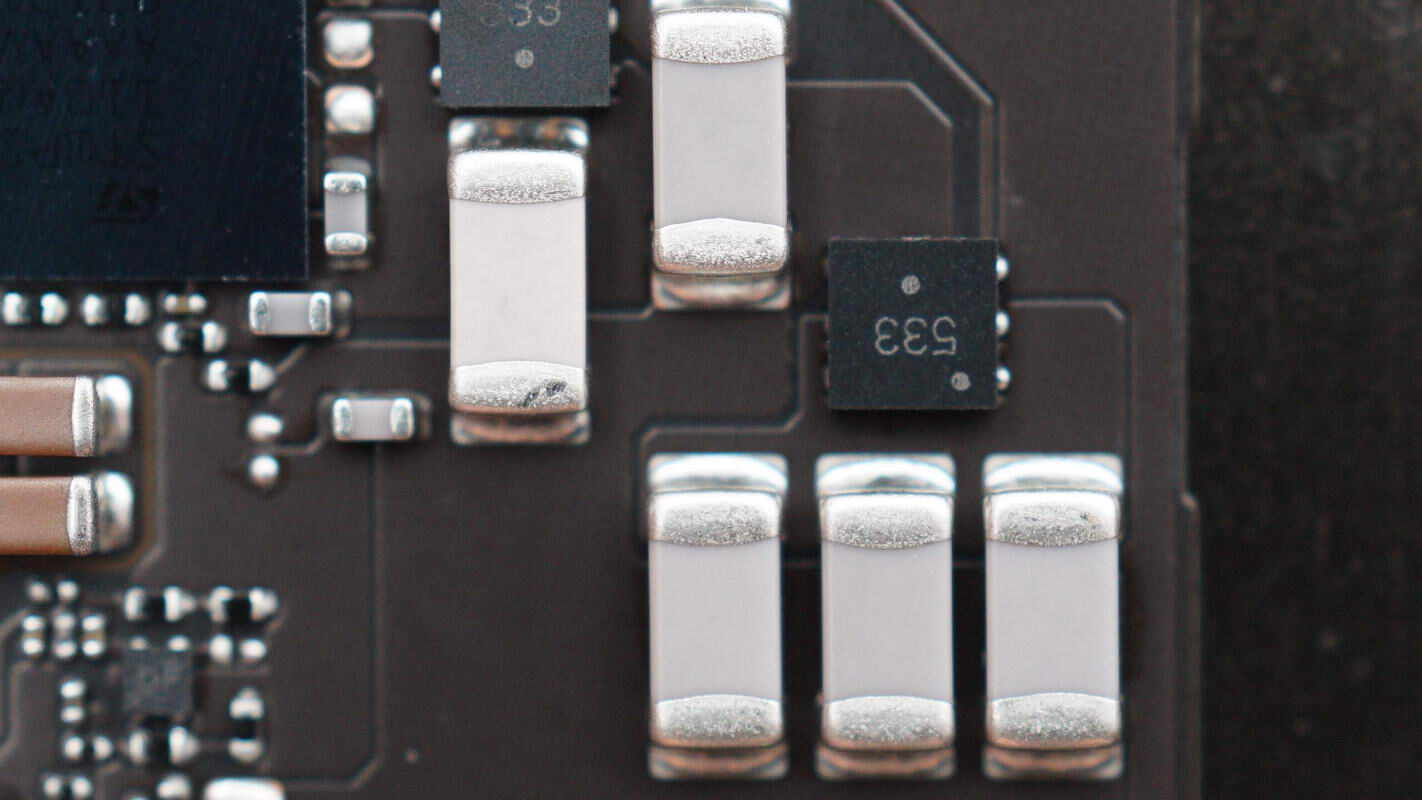
The filtering capacitor is manufactured by Lelon.
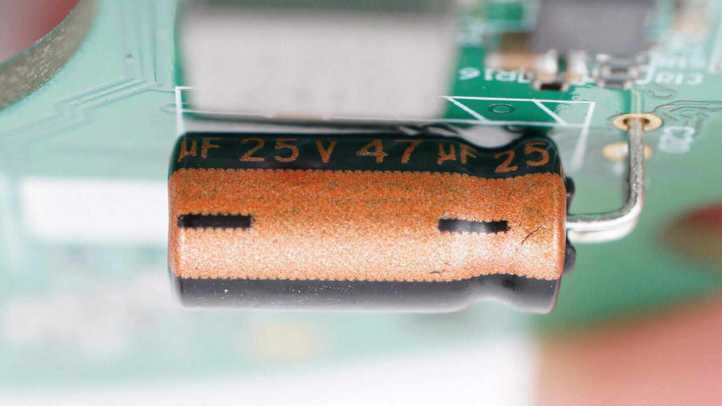
The capacitor is rated at 25V 47μF, and another capacitor on the board has the same part number.
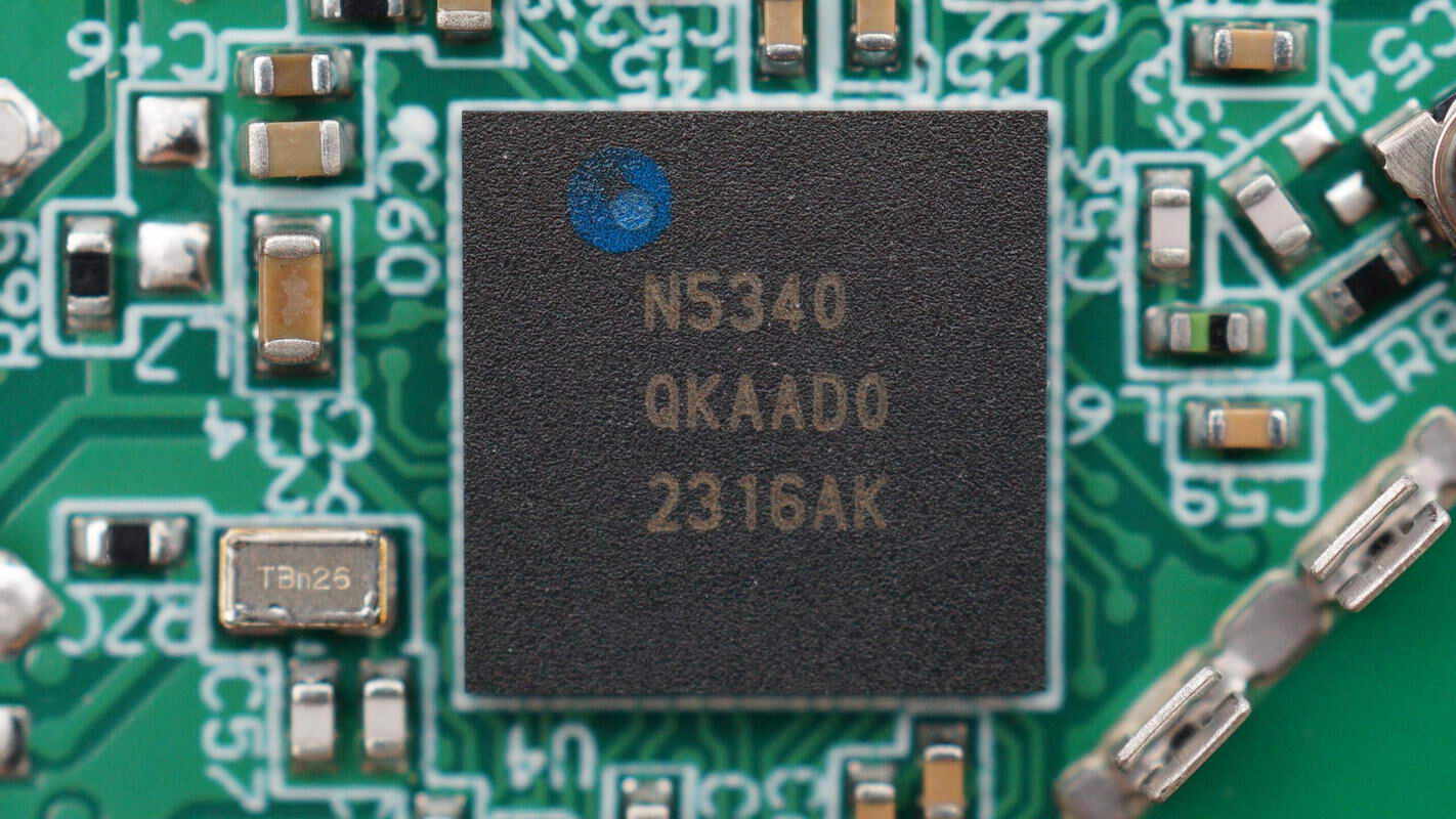
The Bluetooth SoC is from Nordic, model nRF5340. It is the world’s first wireless system-on-chip featuring dual Arm® Cortex®-M33 processors. The chip combines a dual flexible processor architecture with advanced features and supports operation up to 105°C. It comes in an AQFN-94 (7x7 mm) package and is an ideal solution for LE Audio streaming, professional lighting, high-end wearables, and other complex IoT applications.
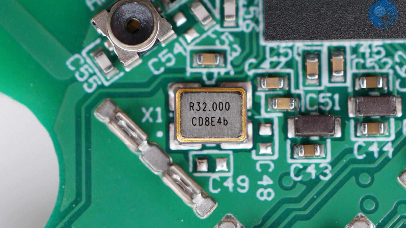
Close-up of the 32.000 MHz clock crystal oscillator.
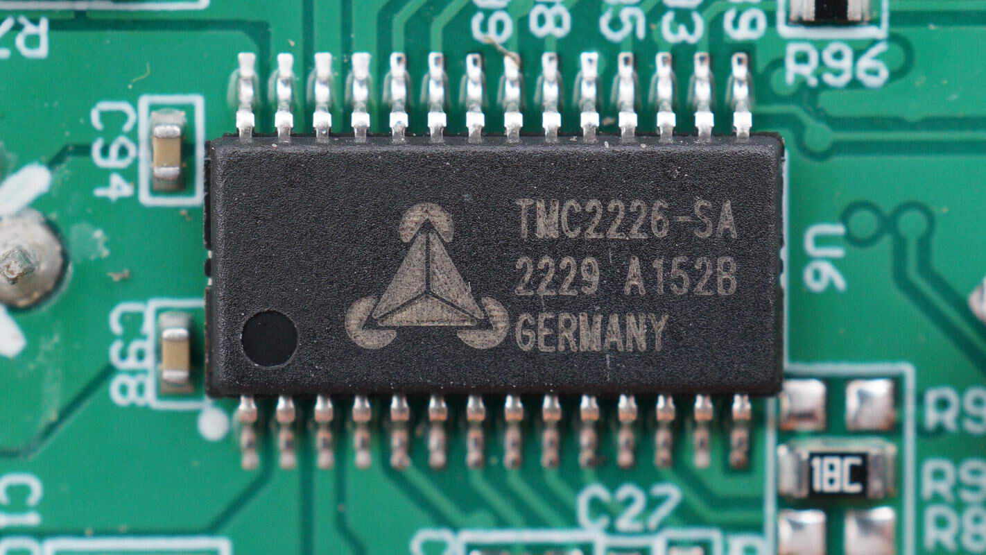
The motor driver chip is from Trinamic, model TMC2226-SA. It is an ultra-silent driver for two-phase stepper motors, featuring advanced StealthChop2 chopper technology for noiseless operation, maximum efficiency, and optimal motor torque. The integrated power MOSFETs can handle motor currents up to 2A RMS. The chip also includes multiple protection and diagnostic features to ensure stable and reliable performance.
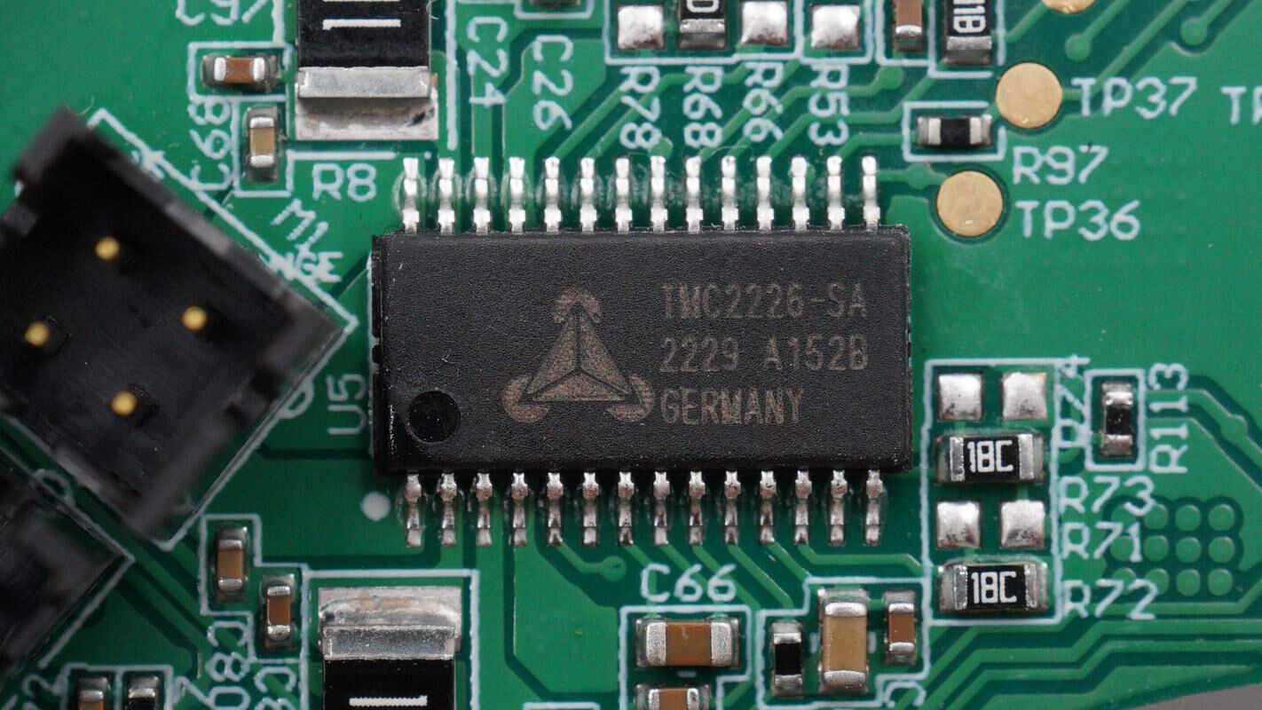
The other motor driver chip is also a Trinamic TMC2226-SA.
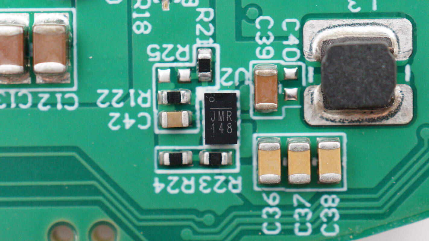
The voltage regulator chip is marked with JMR.
Close-up of the inductor.
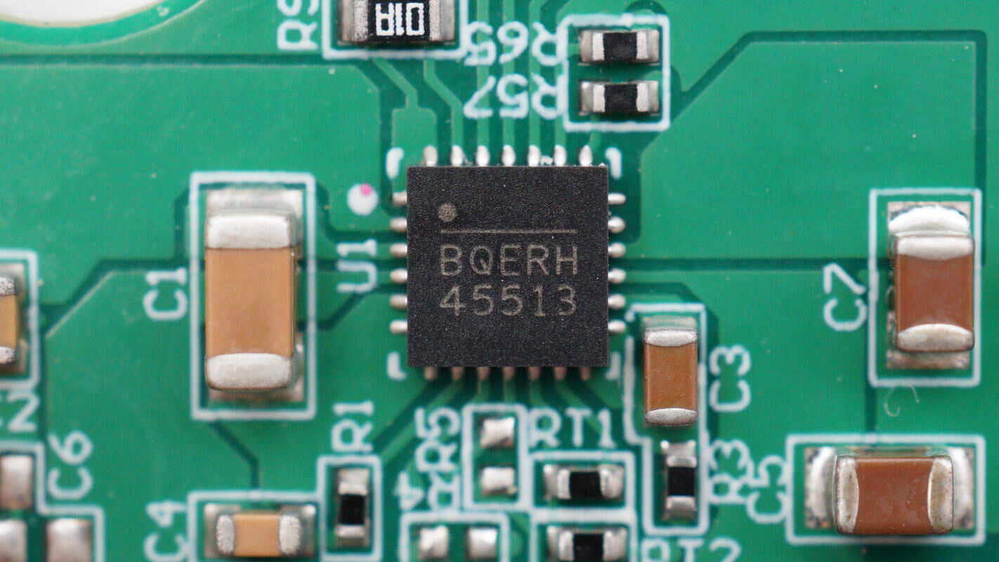
Another voltage regulator chip is marked with BQERH 45513.
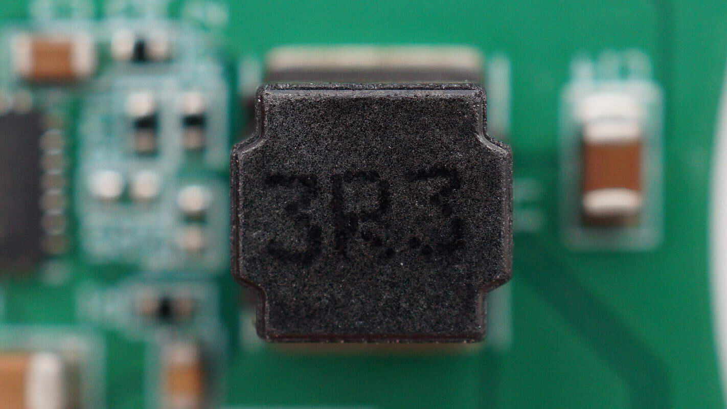
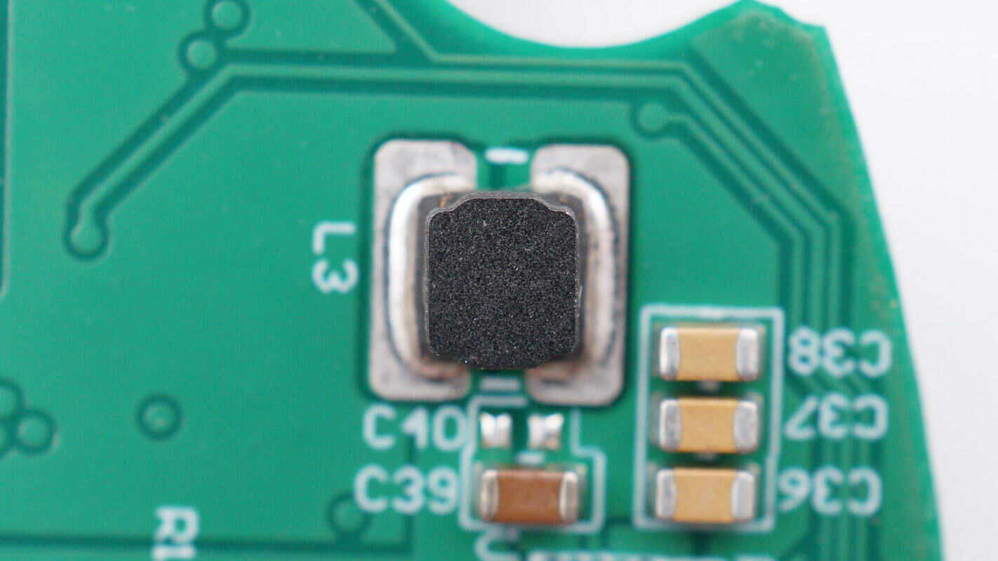
Close-up of the 3.3μH inductor.
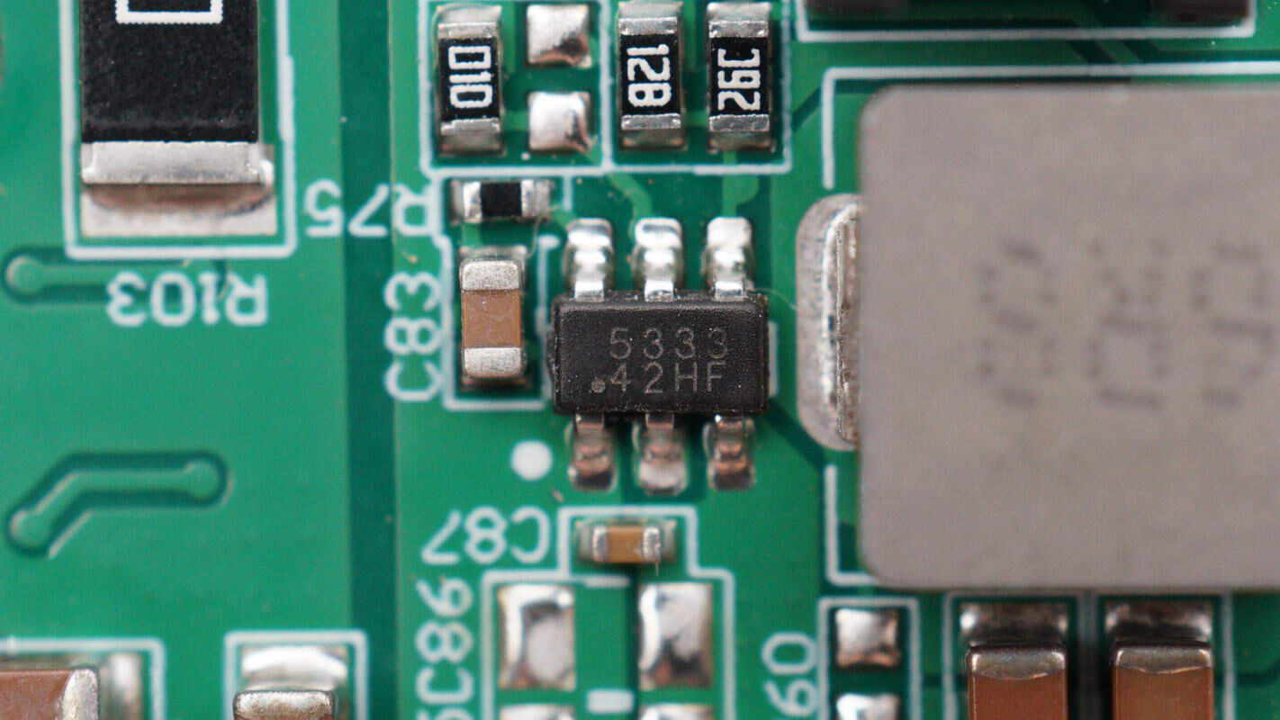
There is also a voltage regulator chip marked with 5333, housed in a SOT-23-6 package.
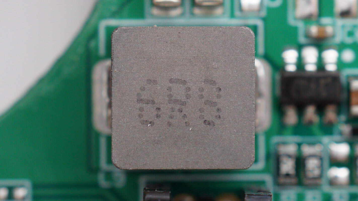
Close-up of the 6.8μH alloy inductor.
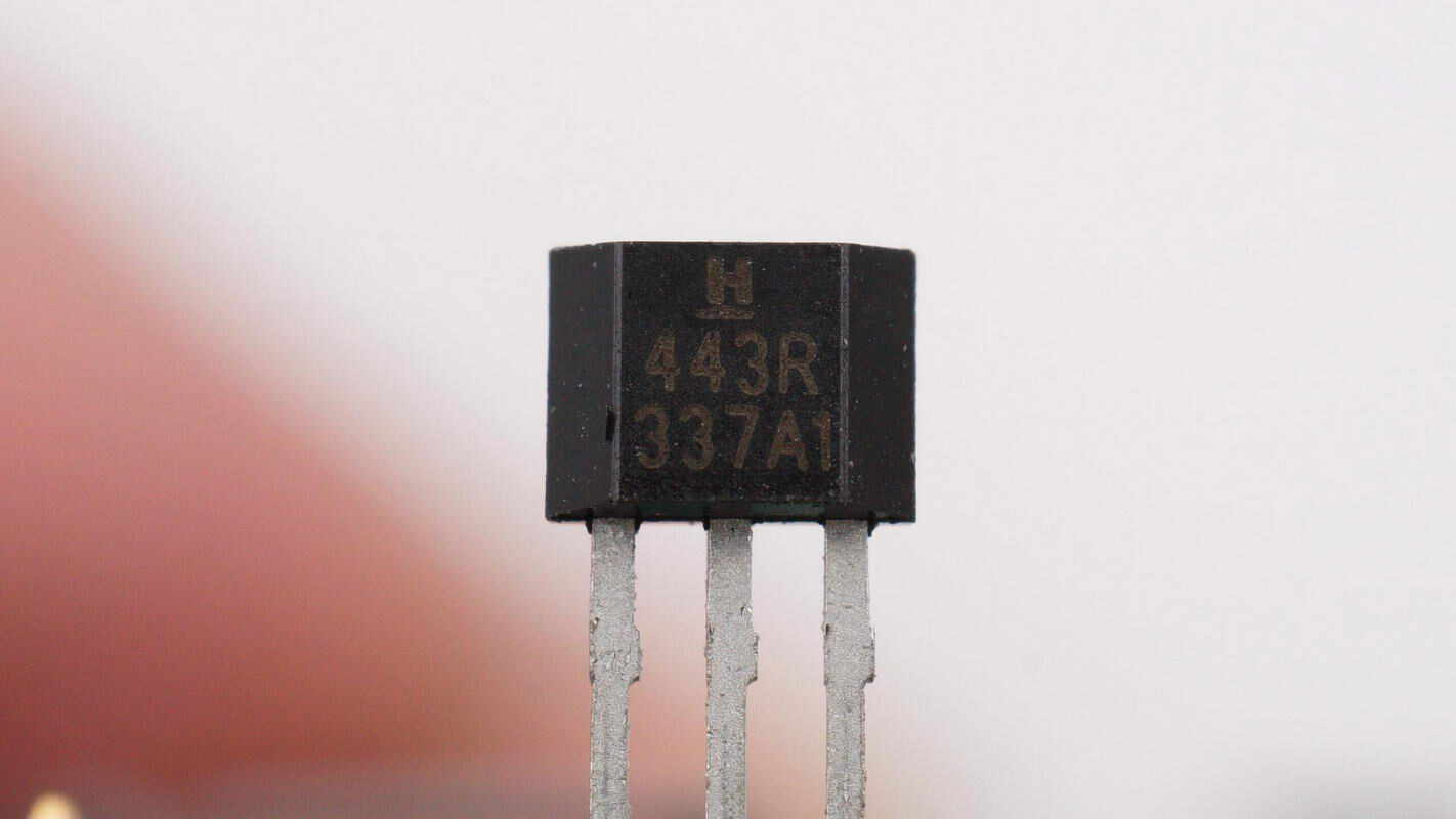
Close-up of a Hall effect sensor.
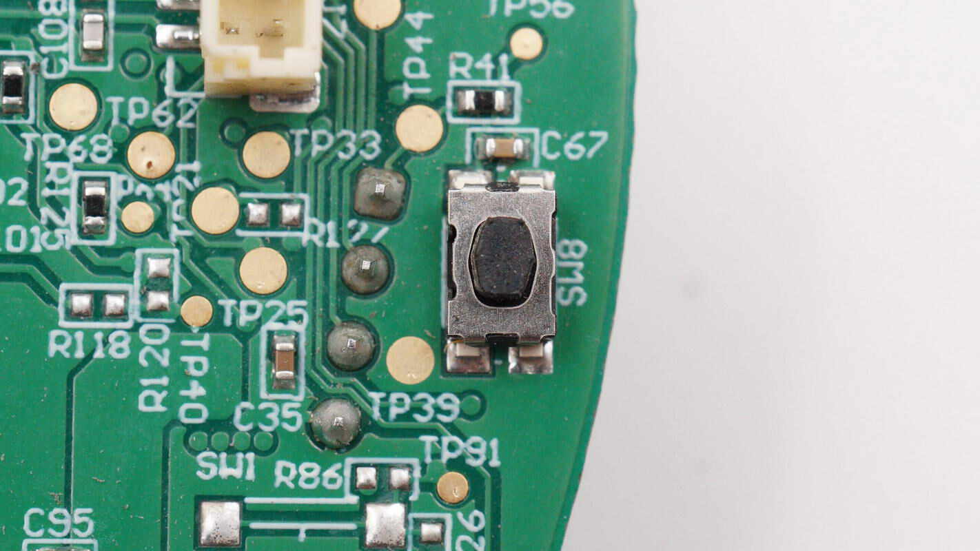
Close-up of an SMD tactile button.
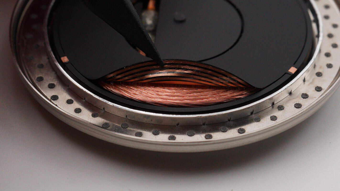
A sensing coil is attached to the wireless charging coil.
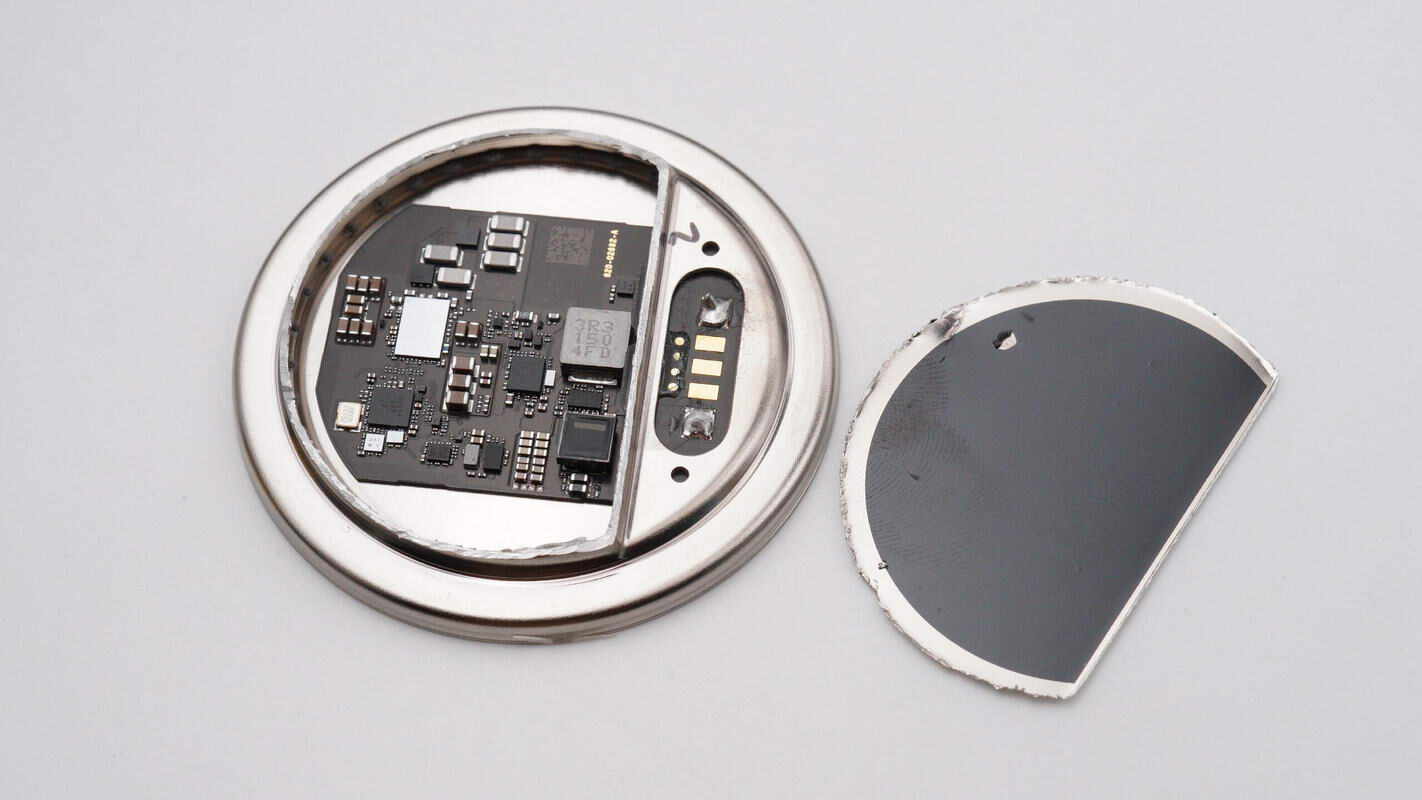
Cut open the metal casing on the back, revealing insulating paper attached to the inside.
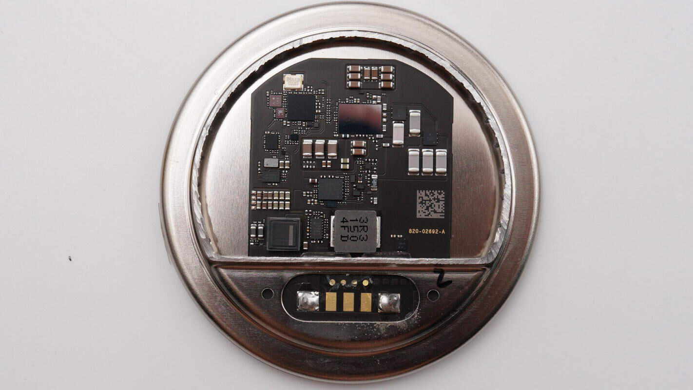
The PCB has components only on the front side.

Close-up of the filter inductor.

Close-up of the load switch marked with 1324V.
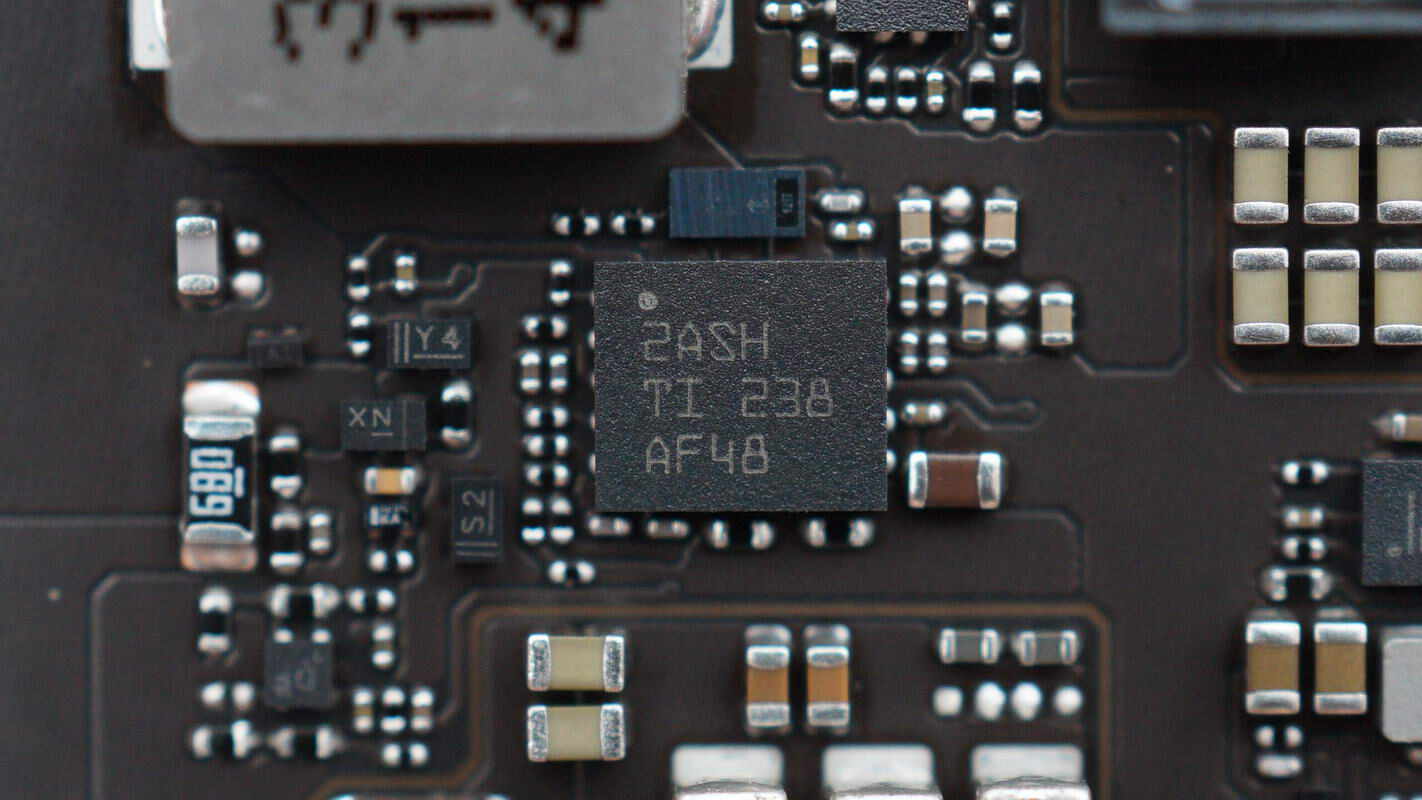
Close-up of the TI TPS61178 boost converter.
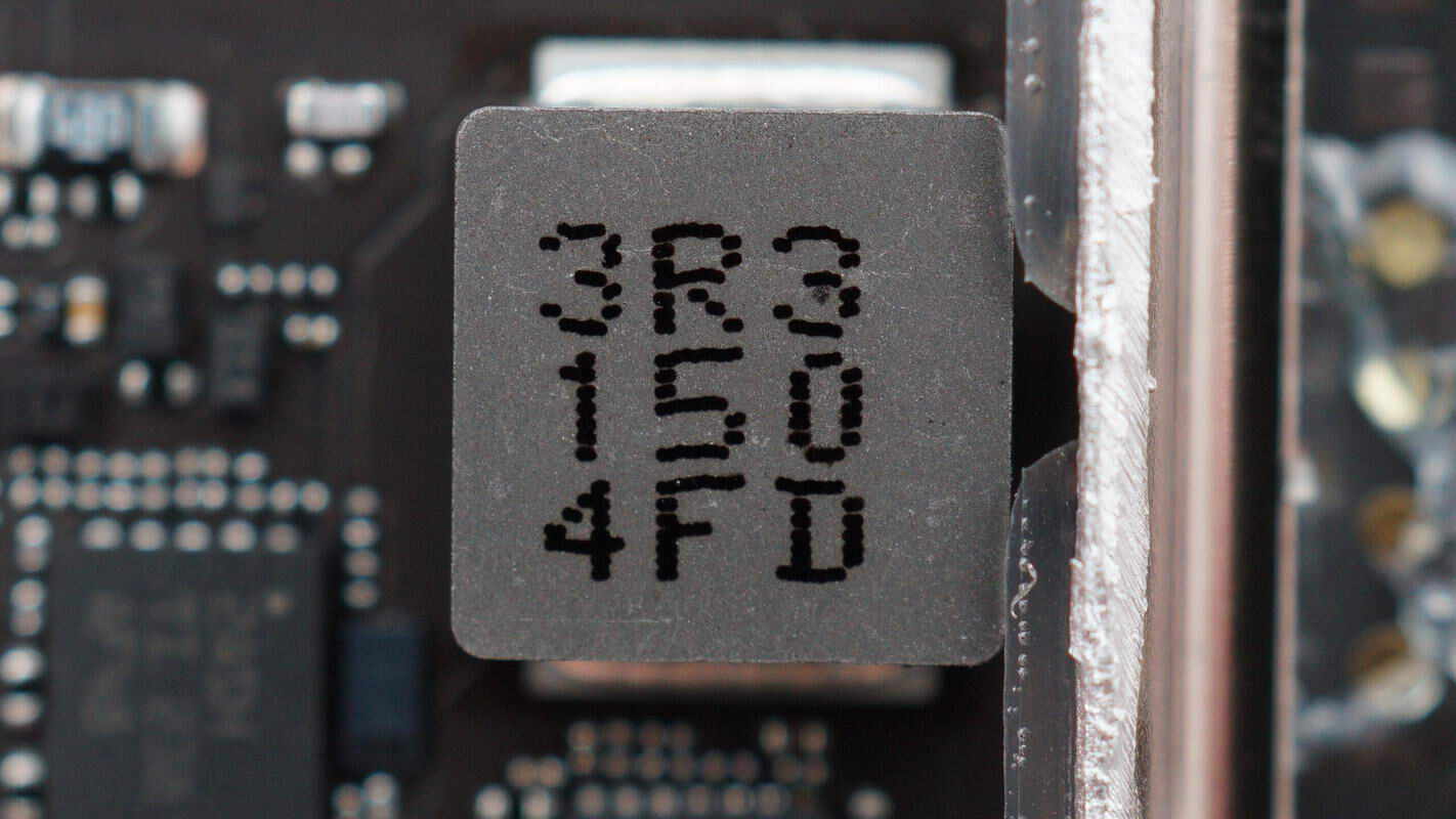
A 3.3μH alloy inductor is used for the boost converter.
The MPS buck regulator IC supplies power to the wireless charging microcontroller.
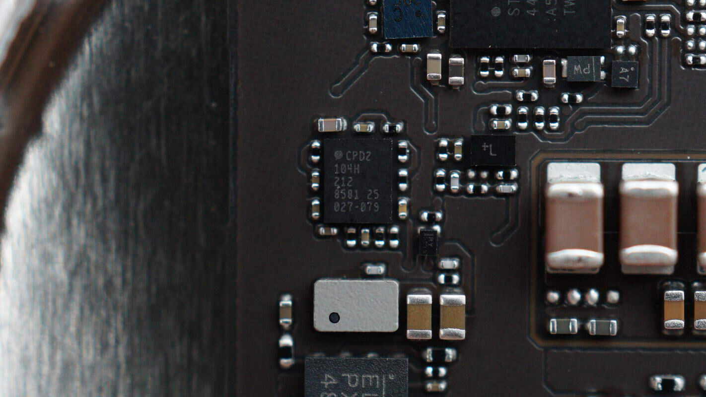
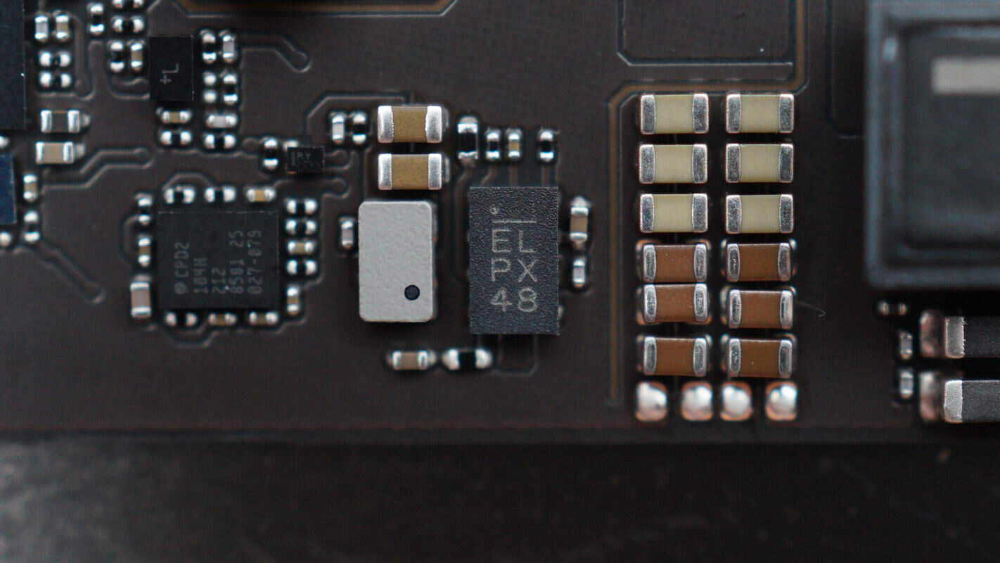
Infineon CYPD2104 Type-C port controller.

The wireless charging master controller chip is the ST STM32F446MEY6, a high-performance ARM Cortex-M4 MCU with DSP and FPU. It features 512 KB Flash memory, a 180 MHz CPU, an ART accelerator, and dual QSPI interfaces.
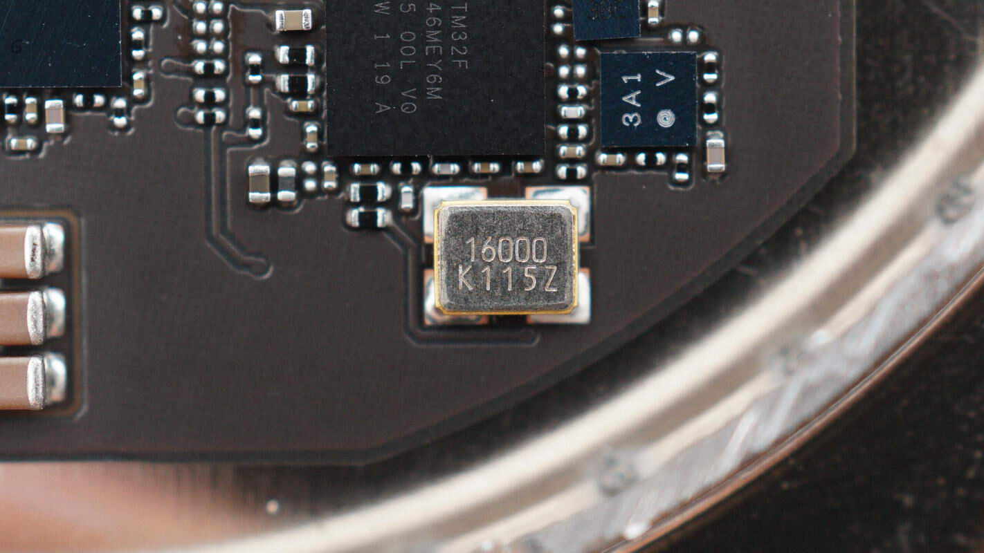
Next to it is a crystal oscillator that provides the clock signal for the master controller chip.

The ST STWPSPA1 is a custom wireless charging controller in a CSP package, featuring an integrated power MOSFET driver and a simplified external component design. According to the IC-level analysis report of the iPhone 12 MagSafe magnetic wireless charger, this controller internally houses two power transistors and uses two external power transistors to form an H-bridge.
Close-up of the NPO resonant capacitors.
Well, those are all components of the Belkin 15W Auto‑Tracking Stand Pro with DockKit.
Summary of ChargerLAB
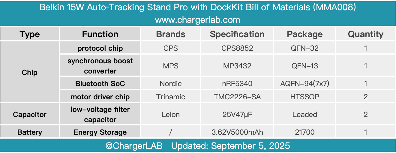
Here is the component list of the Belkin 15W Auto‑Tracking Stand Pro with DockKit for your convenience.
It continues Belkin’s signature minimalist design, made from renewable plastic materials that reflect a low-carbon, eco-friendly philosophy. The base and wireless charging pad support dynamic facial tracking with 360° horizontal and 90° vertical rotation. Simply bring your phone close to connect, with support for Apple Watch camera control. Powered by Apple’s DockKit facial tracking technology, it enables impressive results even when shooting solo.
It functions both as an auto-tracking gimbal and a wireless charging stand. The bottom features a standard 1/4-inch threaded nut, allowing it to be mounted on camera tripods and other supports. Notably, to provide 15W wireless charging for your phone, the device must be connected to a power source; the built-in battery is solely for powering the auto-tracking function.
After taking it apart, we found that the internal PCB connects to the motor, slip ring, battery, and other components via plug-and-play connectors. It uses the CPS CPS8852 protocol chip for input control, the MPS MP3432 boost converter for charging, the Nordic nRF5340 for Bluetooth connectivity, and Trinamic TMC2226-SA motor driver chips to drive the motors.
Related Articles:
1. Teardown of RayNeo Air 3s Pro Original USB-C Adapter (XRAC-CHA01OS)
2. Teardown of Xiaomi Mijia Sonic Sweep Electric Toothbrush (MES611)
3. Teardown of GreatWall 2200W 80 PLUS Platinum Server Power Supply (CRPS2200DLW)