Introduction
This teardown features an Aohai Technology 3200W 80PLUS Titanium CRPS server power supply, model AH-CRPS3200A1A. The unit supports 100–240V AC input as well as 240V HVDC input and is certified to 80PLUS Titanium efficiency standards. The rated main output voltage is 12.2V with a maximum output current of 262.3A. The standby power rail provides 12V at 2.1A.
On the input side, the power supply is equipped with a cooling fan, an AC inlet, and status indicators. The output side uses a gold-finger connector interface. Internally, the design is based on a dual-switch bridgeless PFC stage, a full-bridge LLC resonant converter, and synchronous rectification. The power supply employs Microchip controllers and supports PMBus communication. Next, let’s take a closer look at its internal components and design.
Product Appearance
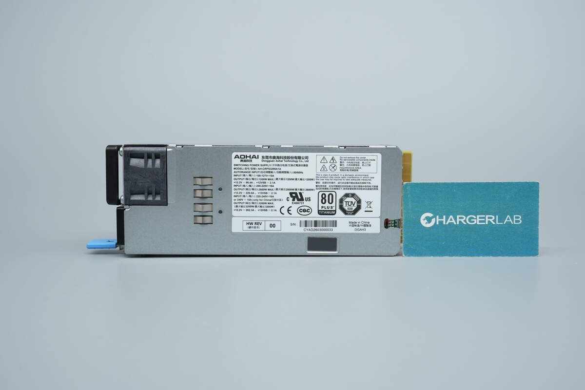
It uses a metal enclosure with an information label affixed to the housing. A cooling fan and grounding spring contacts are located on the left side.
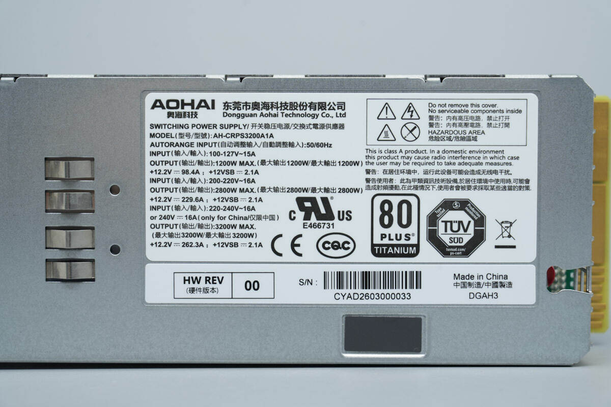
Model: AH-CRPS3200A1A
Input: 100–127V~ 15A
Output: 1200W MAX +12.2V ⎓ 98.4A; +12VSB ⎓ 2.1A
Input: 200–220V~ 16A
Output: 2800W MAX +12.2V ⎓ 229.6A; +12VSB ⎓ 2.1A
Input: 220–240V~ 16A or 240V ⎓ 16A (China only)
Output: 3200W MAX +12.2V ⎓ 262.3A; +12VSB ⎓ 2.1A
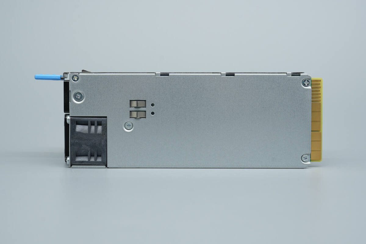
The rear side features mounting screws and grounding spring contacts.
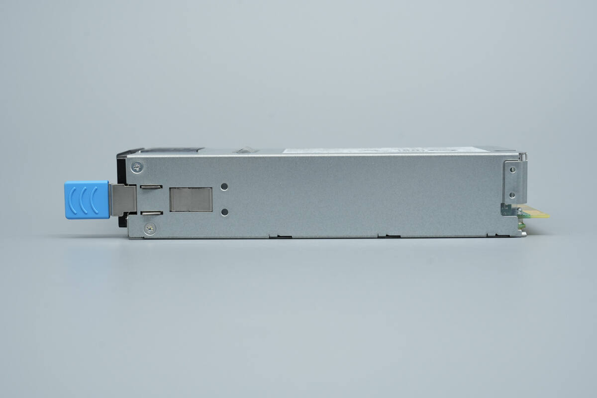
A retaining latch is located on the side.
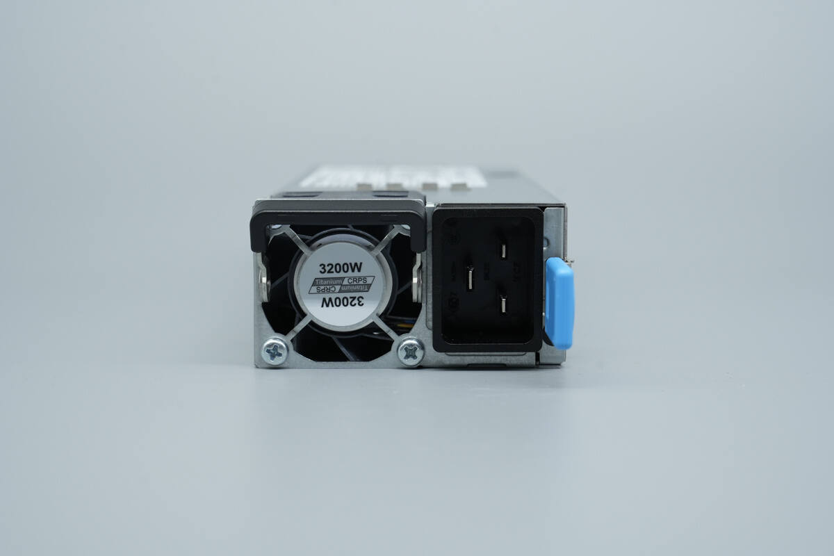
The input side is equipped with a cooling fan, an input connector, a release handle, and a power status indicator.
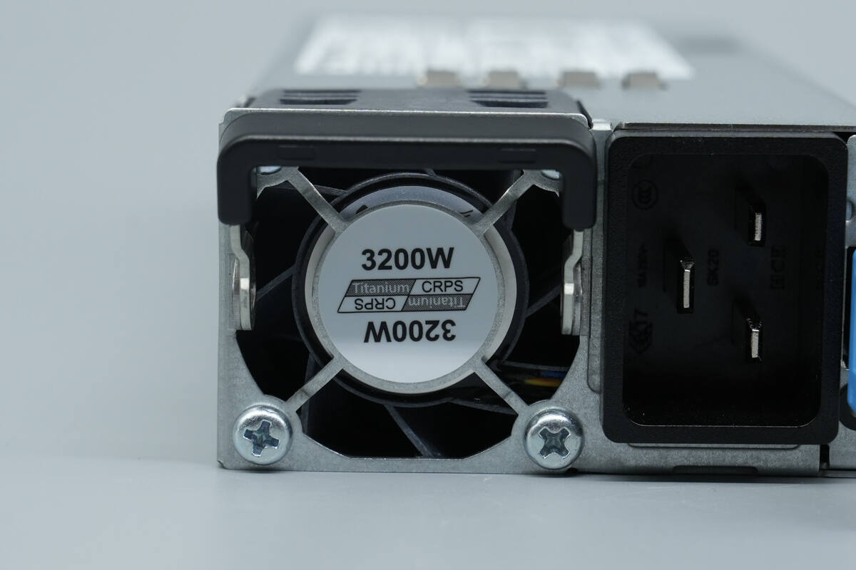
The cooling fan is fitted with a protective grille, marked with “Titanium” and “3200W”.
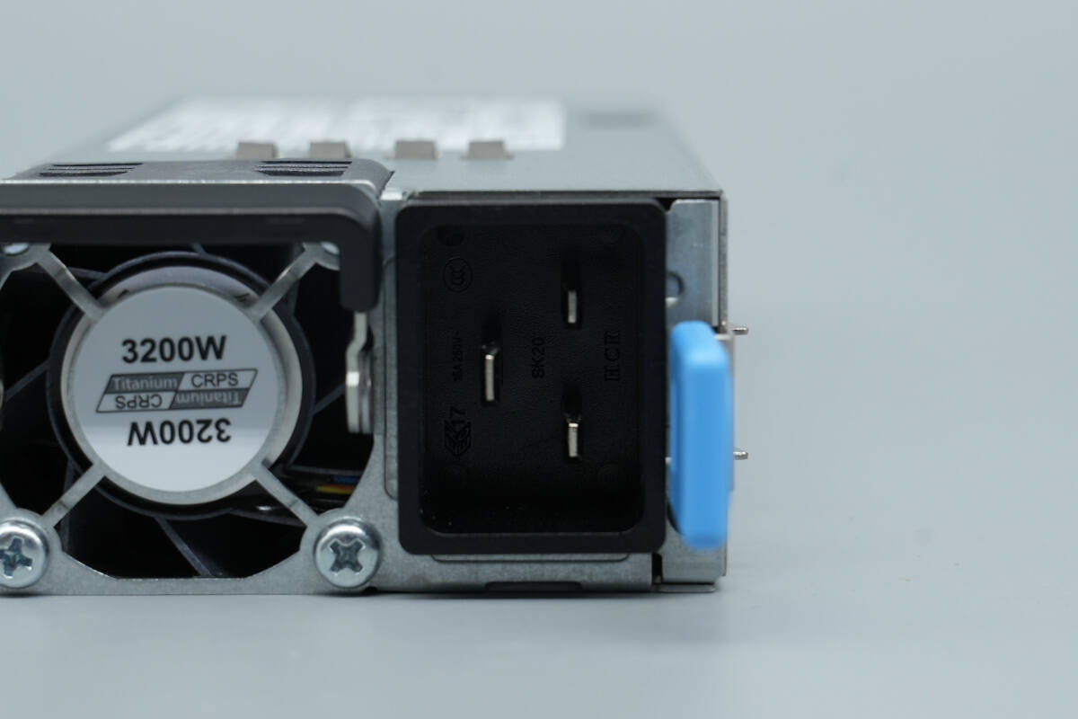
It uses a C20 inlet, with an LED indicator located below the release handle.
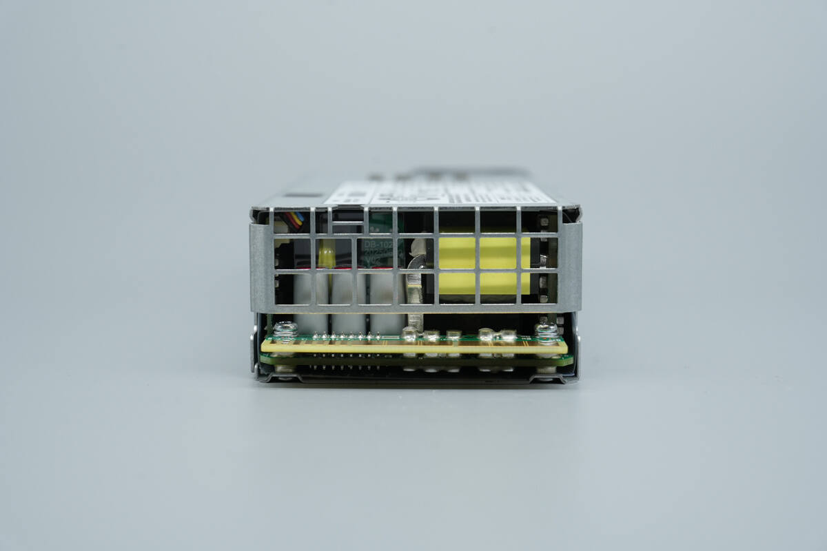
The output side features a protective grille and a gold-finger connector.
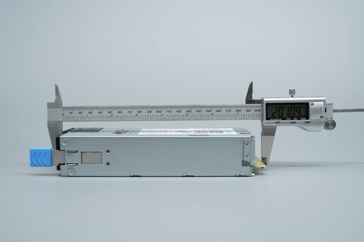
The length of the power supply is about 201 mm (7.91 inches).

The width is about 74.1 mm (2.92 inches).
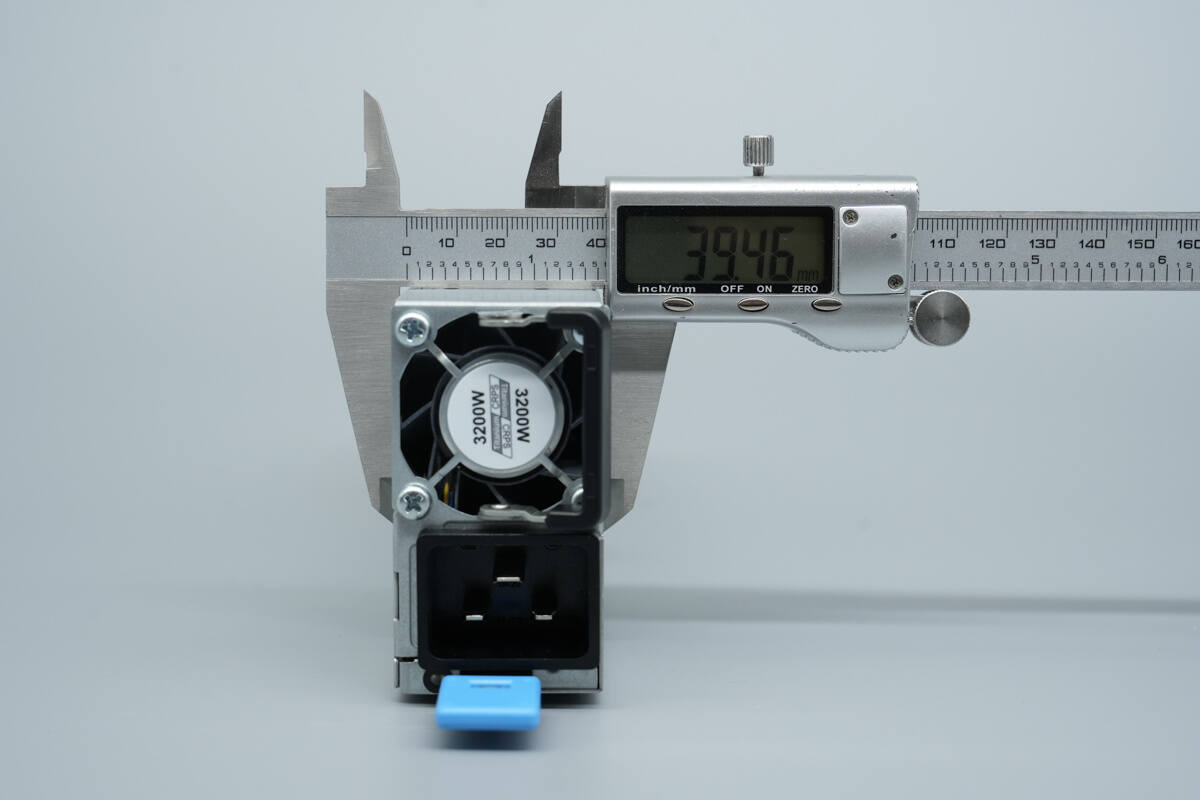
The thickness is about 39.5 mm (1.56 inches).
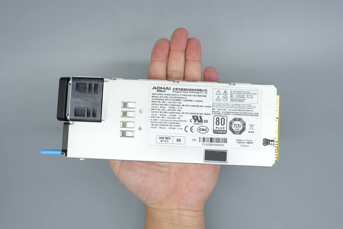
That's how big it is in the hand.
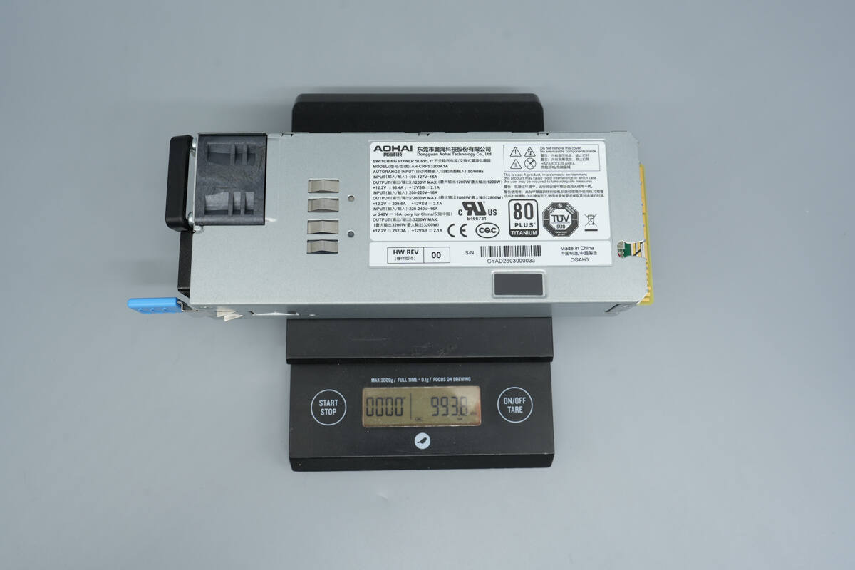
The weight is about 994 g (35.062 oz).
Teardown
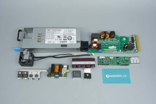
Next, let's take it apart to see its internal components and structure.
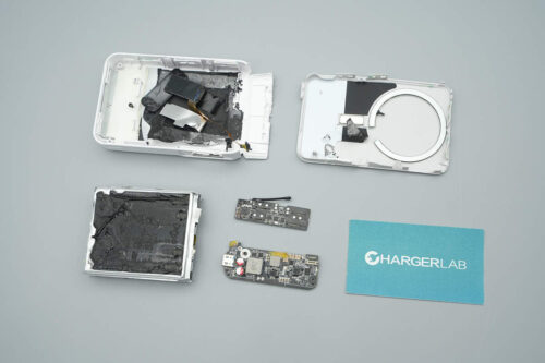
The PCBA module is elongated, with the input connector soldered directly onto the PCB.
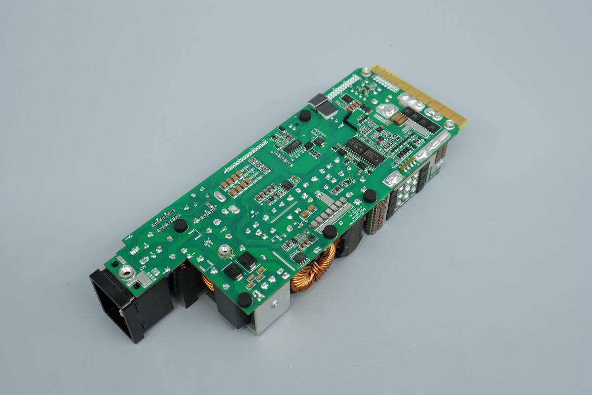
The back of the module has screw holes and is fitted with rubber pads.

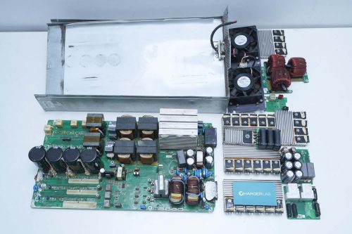
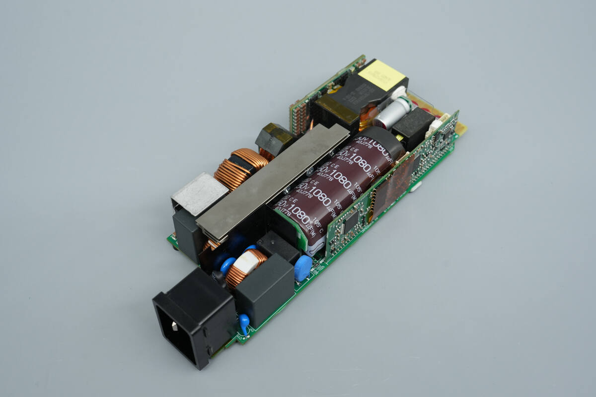
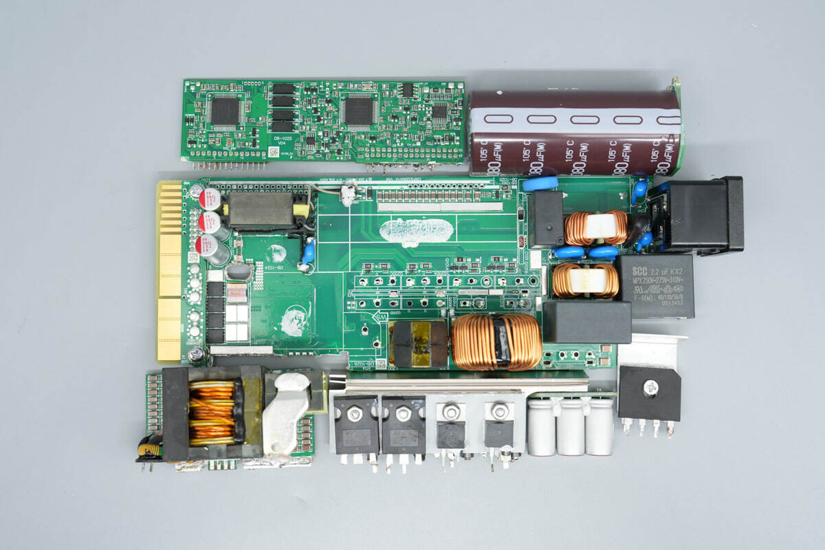
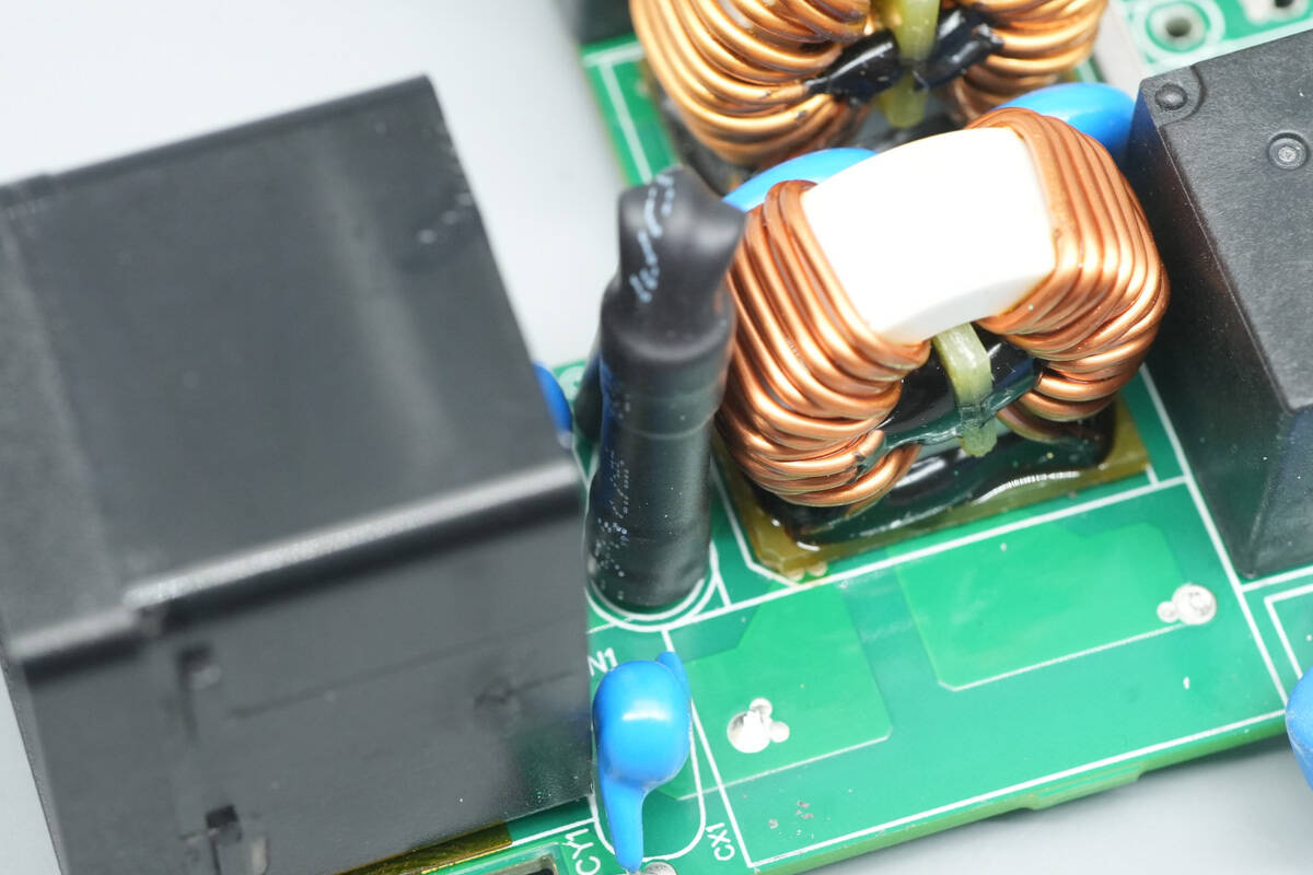
Front view of the PCBA module. On the left side is the AC input section, which includes, in order: blue Y capacitors, a fuse, safety-rated X2 capacitors, common mode chokes, a relay, a PTC thermistor, PFC MOSFETs, PFC rectifiers, and LLC MOSFETs.
On the upper left are the bridge rectifier, PFC boost inductor, and resonant inductor. On the right side are the transformer and synchronous rectification PCB, filter inductors, filter capacitors, and the standby power transformer.

On the back, the right side features two rectifier diodes, a current-sensing chip, and a resonant capacitor. Below are the drivers and MLCC capacitors. On the left side are the output control MOSFETs, isolation drivers, and the standby power IC.
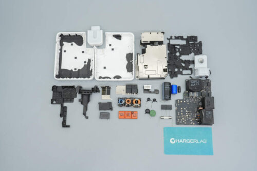
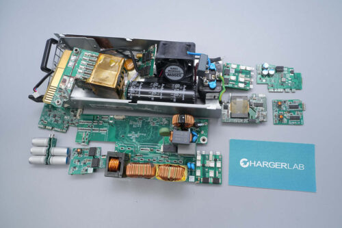
After removing most of the components, the teardown continues.
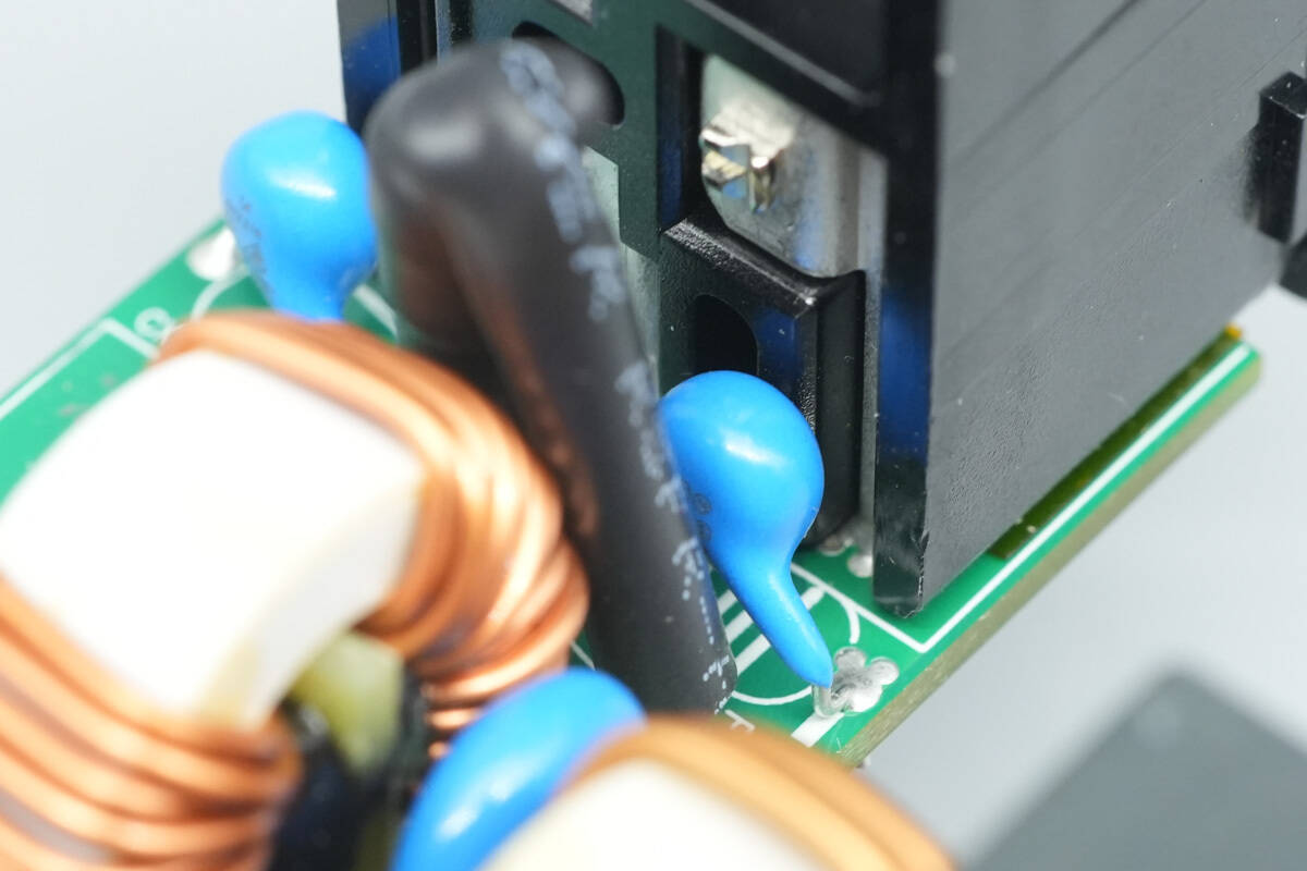
Behind the input connector are two blue Y capacitors.
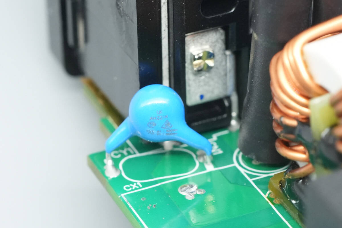
The Y capacitors are from Walsin, part number AH221K.
The fuse is insulated with a heat-shrink tube.
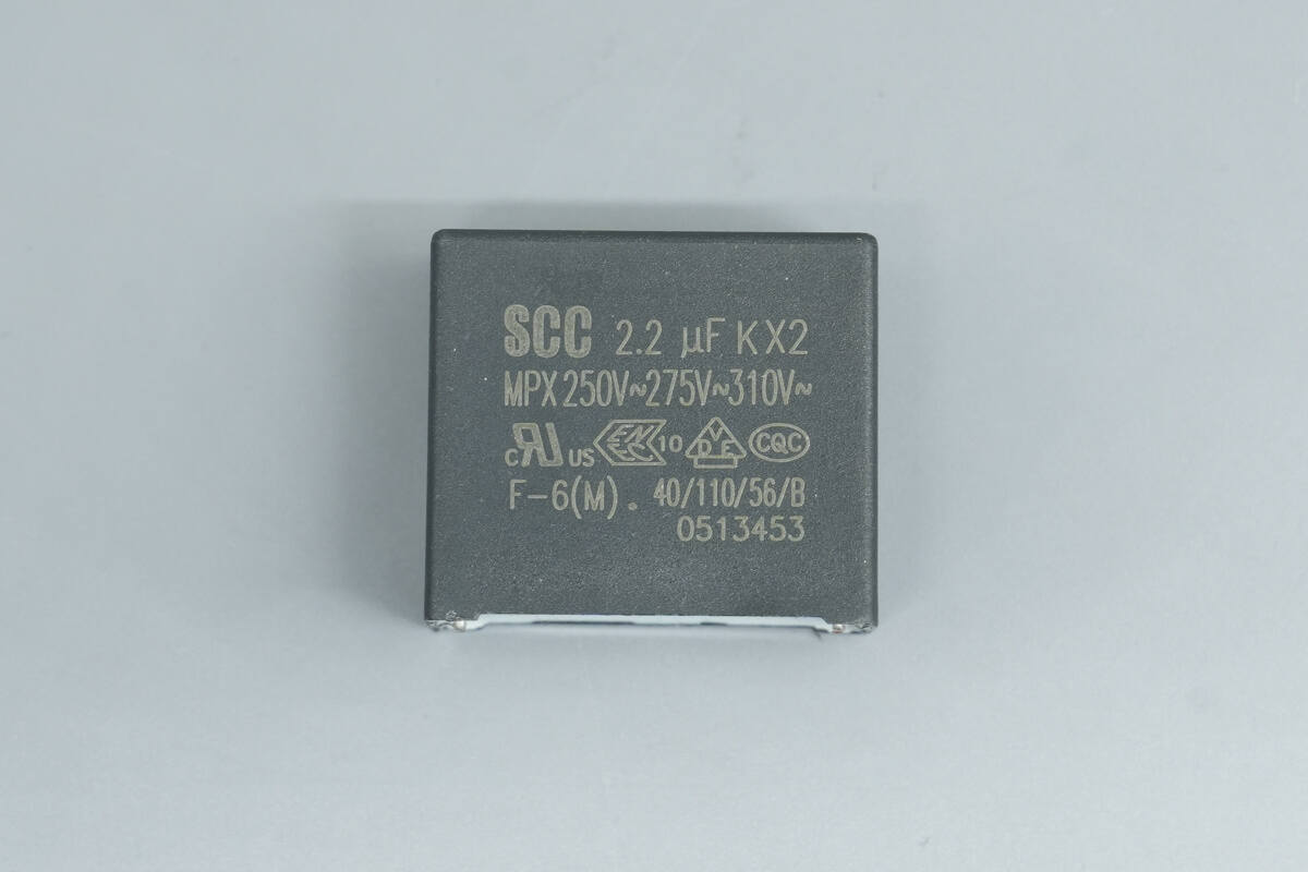
The safety X2 capacitor is from SCC, with a specification of 2.2 μF.

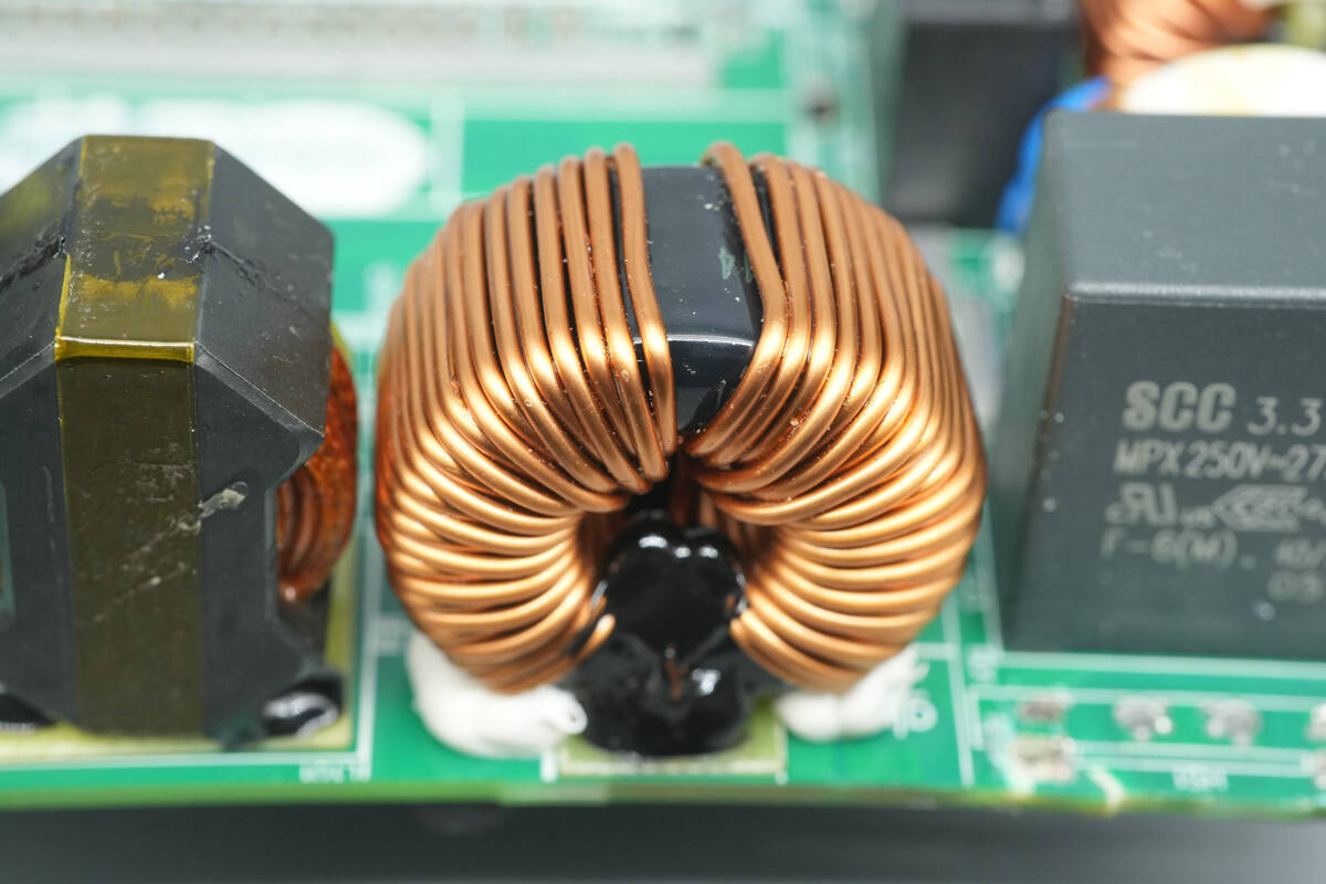
The common mode chokes are wound with enameled wire, with a bakelite insulating board at the bottom.
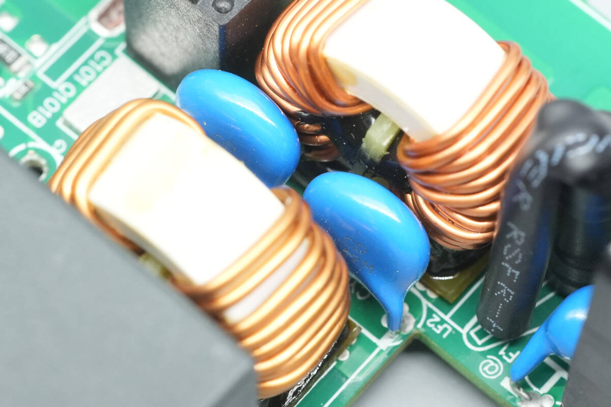
Two blue Y capacitors are placed between the two common mode chokes.
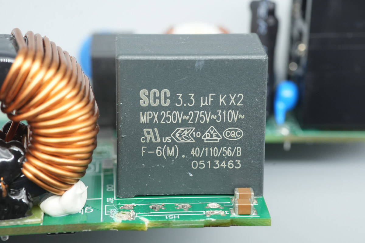
The safety X2 capacitor has a specification of 3.3 μF.
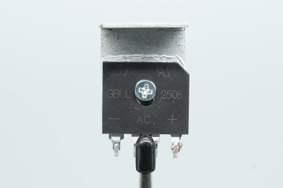
The bridge rectifier is from YJ, model GBUL2508. It is a low-drop bridge rectifier rated at 800 V, 25 A, and uses a GBU package.
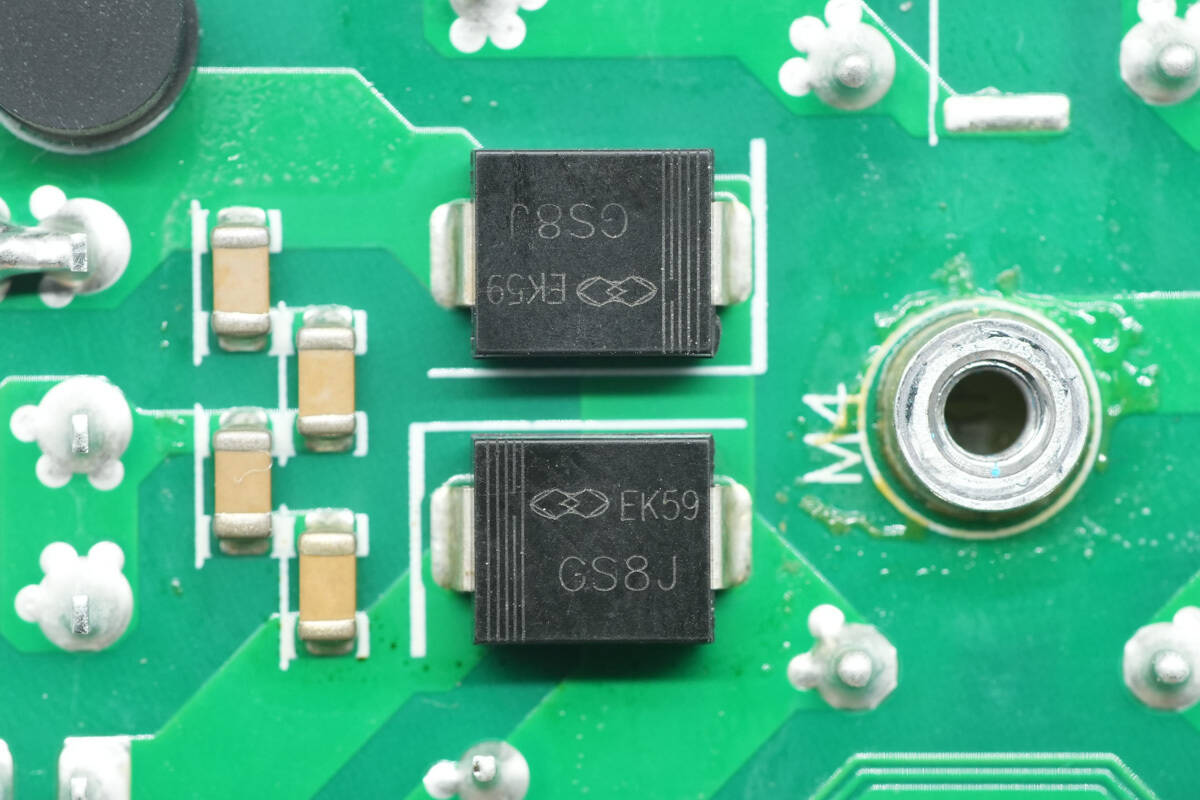
The rectifier diodes are from Gulf Semiconductor, model GS8J, rated at 600 V, 8 A, and use an SMC package.
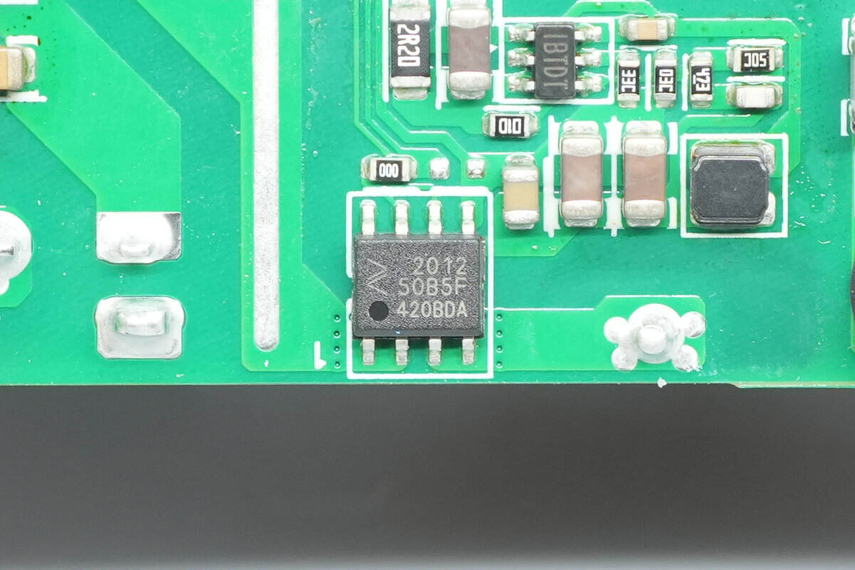
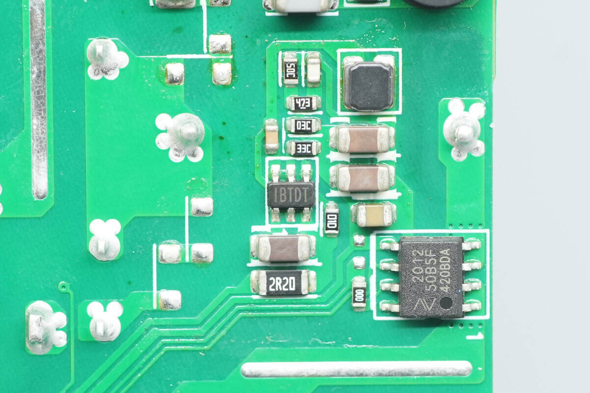
The current-sensing chip is from NOVOSENSE, model NSM2012-50B5F, with a range of 50 A and a supply voltage of 5 V. It features 3 kV isolation and comes in an SOP8 package.
The heatsink houses the PFC MOSFETs and the full-bridge LLC MOSFETs.

On the opposite side are the full-bridge LLC MOSFETs and the PFC rectifiers.
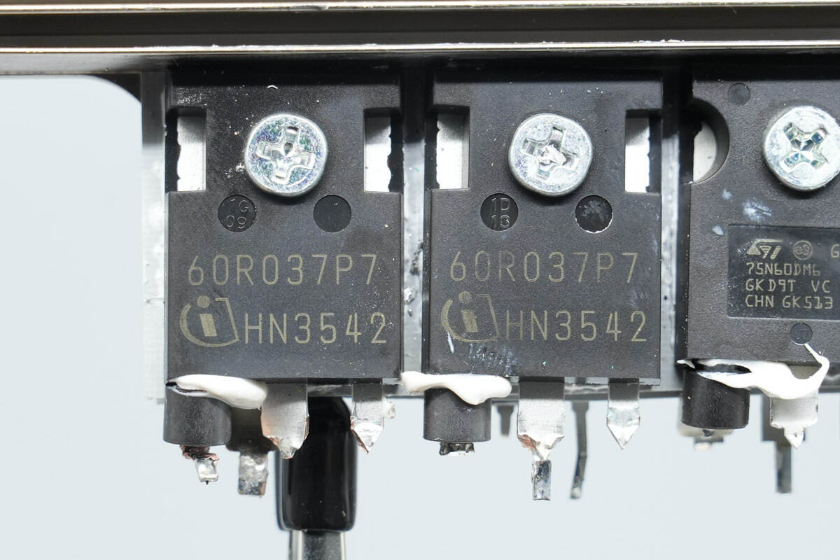
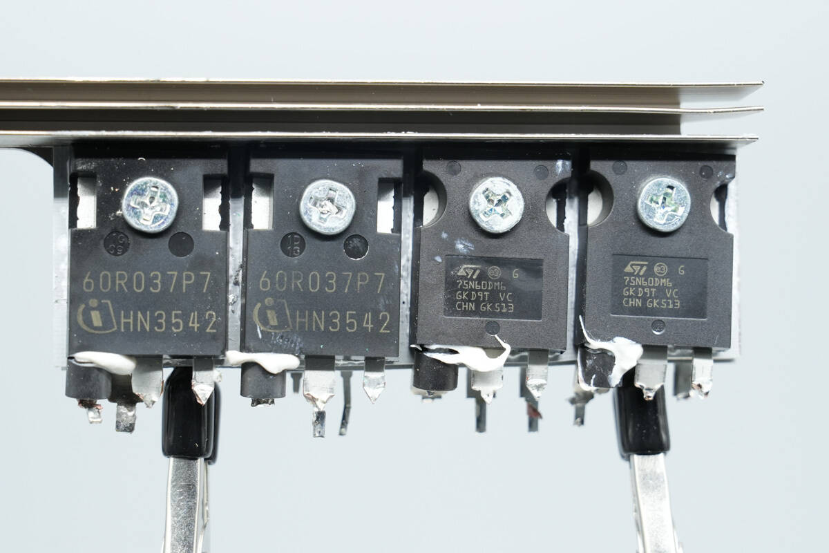
The PFC MOSFETs are from Infineon, model IPW60R037P7, part of the CoolMOS P7 series. They are NMOS devices rated at 650 V with an on-resistance of 37 mΩ, and come in a TO‑247‑3 package.
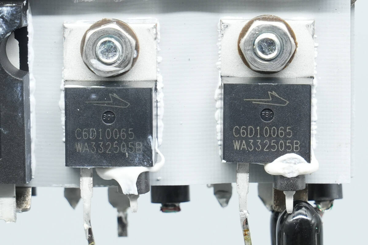
The PFC rectifiers are from Wolfspeed, model C6D10065A. They are sixth-generation SiC Schottky diodes, rated at 650 V, 10 A, and use a TO‑220‑2 package.
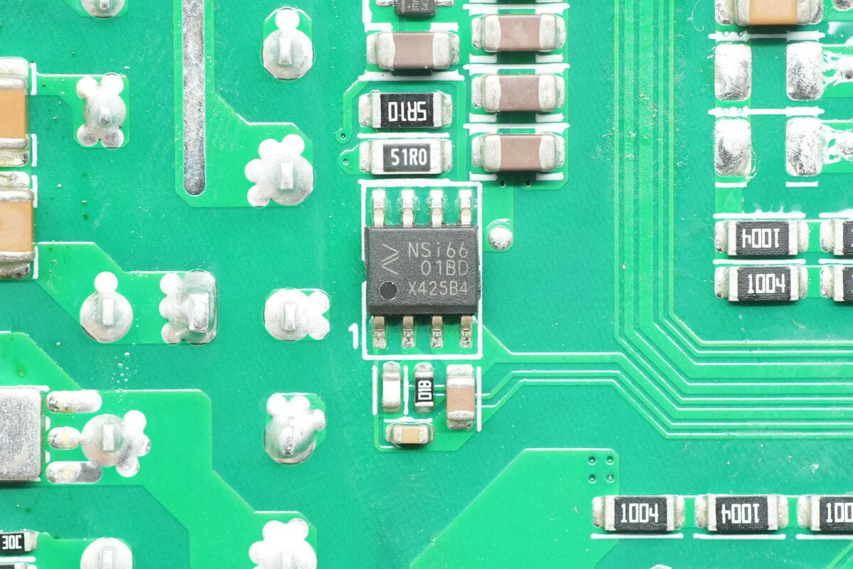
The driver is from NOVOSENSE, model NSi6601BD. It is a single-channel isolation driver with 3 kV isolation, capable of 5 A peak drive current, supporting an operating voltage of 3.1–17 V, and comes in an SOP8 package.
The PFC boost inductor is wound with enameled wire and has a bakelite insulating board at the bottom.

The relay is model A16-S-112HA2F, featuring a single normally open contact with a contact rating of 16 A at 250 V~, and a coil voltage of 12 V.
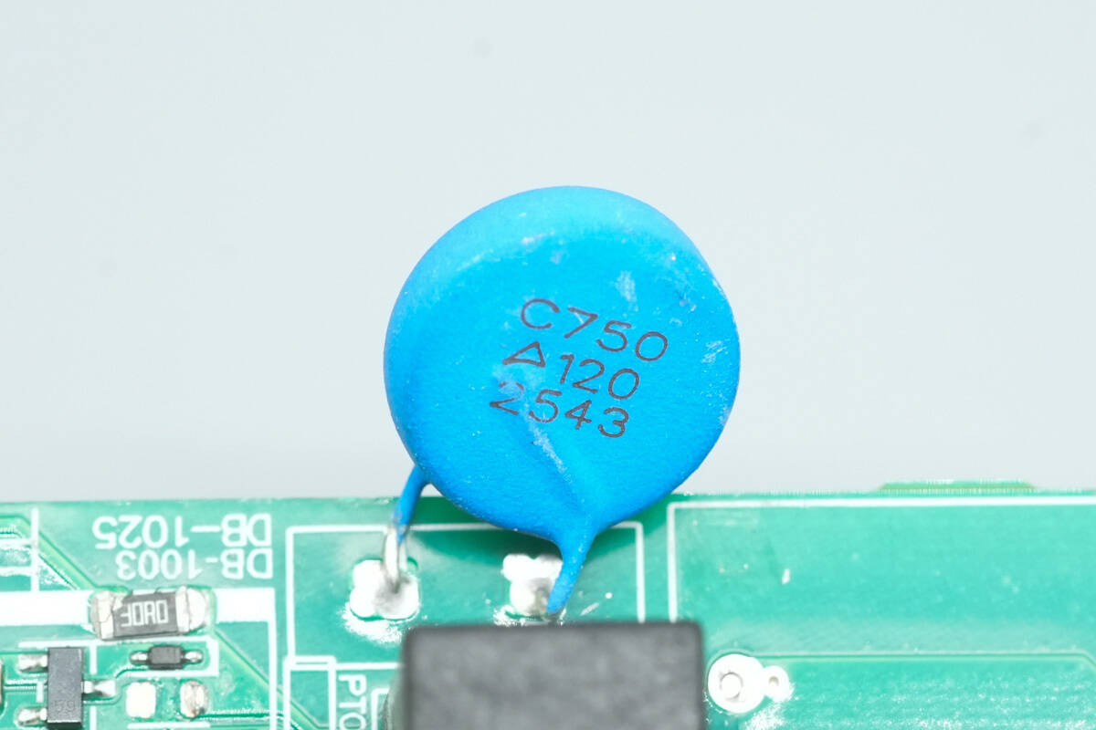
The PTC thermistor is from TDK, model C750, with a resistance of 25 Ω, an AC voltage rating of 280 V, and a DC voltage rating of 400 V.

The high-voltage filter capacitor is from NCC, rated for 105 °C, with a specification of 450 V, 1080 μF.
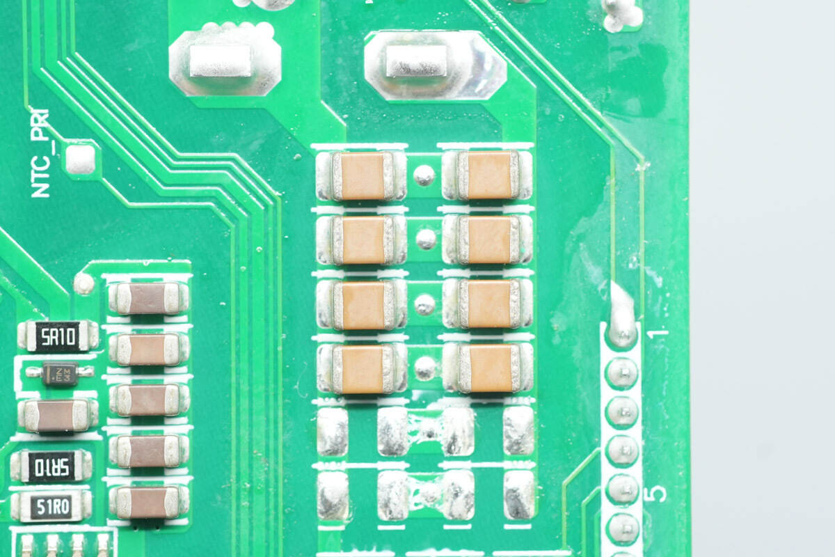
The MLCC capacitors are connected in parallel with the high-voltage capacitor for filtering.
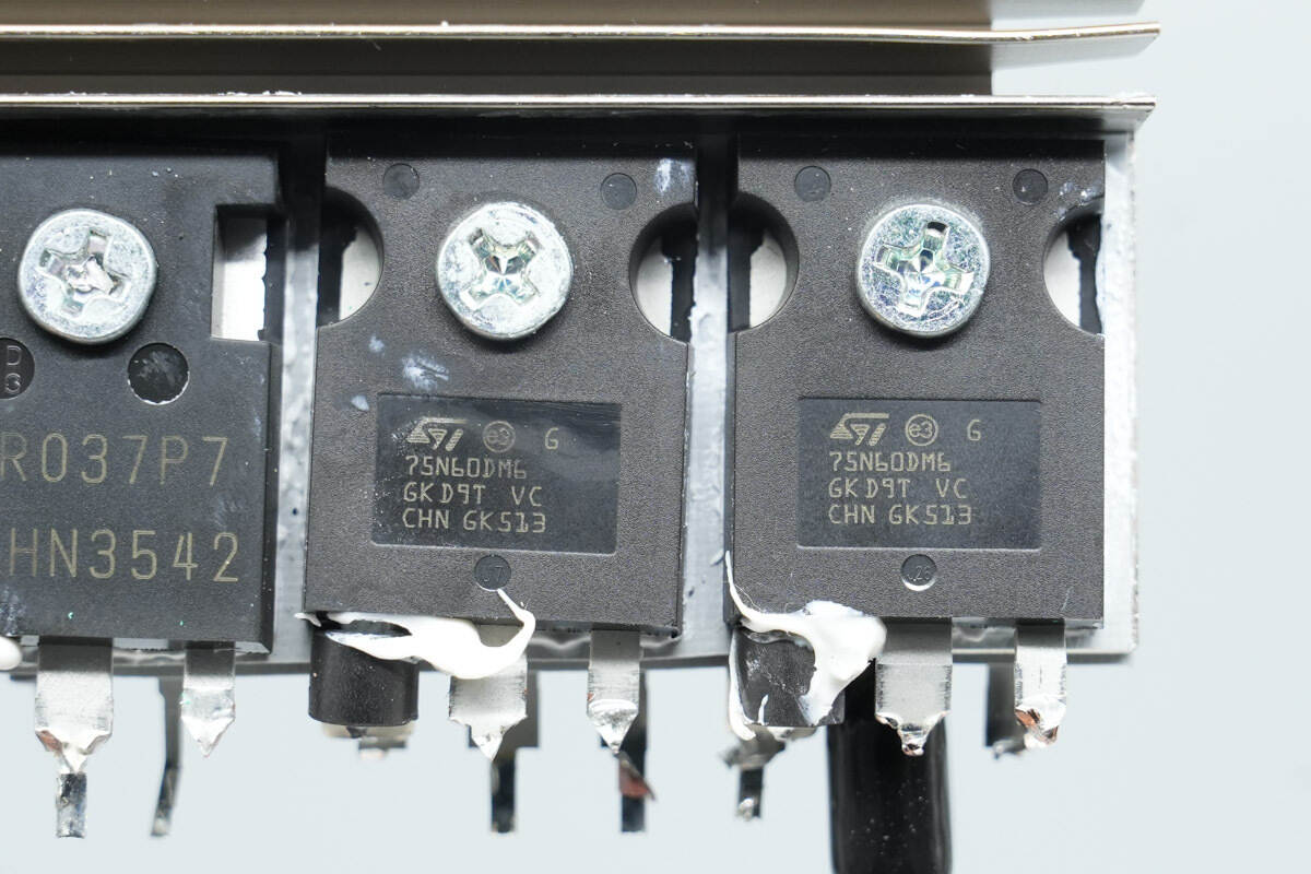
The LLC MOSFETs are from STMicro, model STW75N60DM6. They are NMOS devices rated at 600 V with an on-resistance of 32 mΩ, and come in a TO‑247 package.
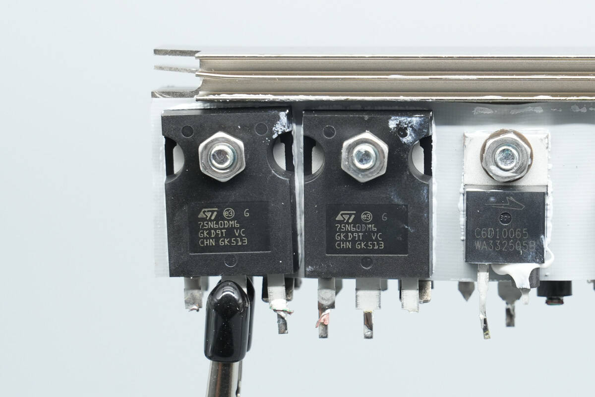
The other two MOSFETs have the same model.
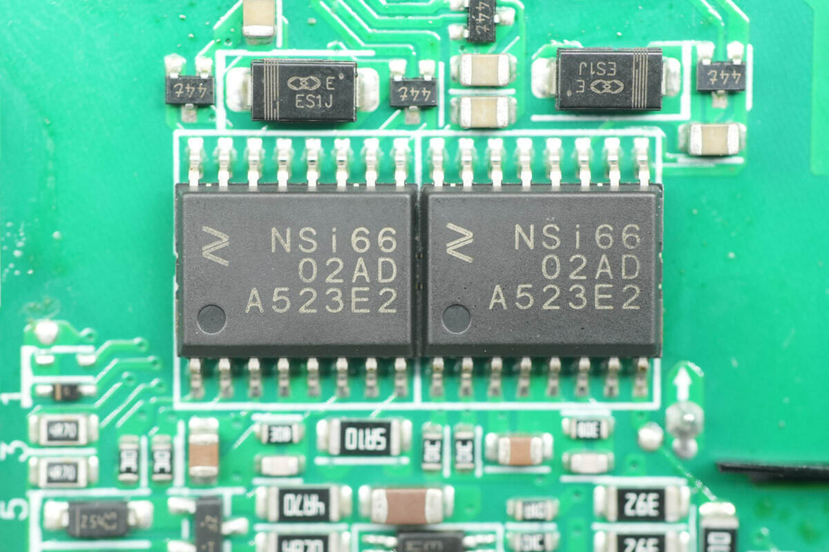
The isolation drivers are from NOVOSENSE, model NSi6602AD. They are dual-channel isolated gate drivers with 5.7 kV rms isolation, capable of 4 A source current and 6 A sink current, and come in SOW16 packages.
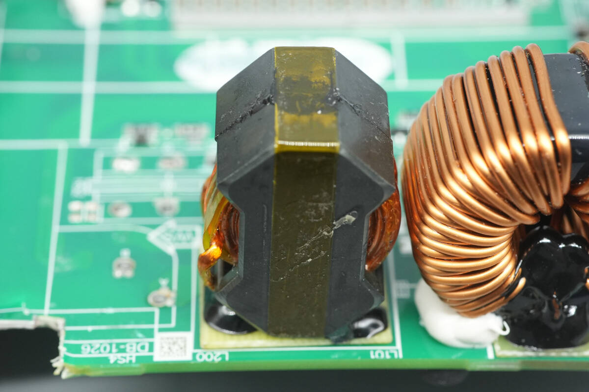
The resonant inductor is wound with Litz wire and has a bakelite insulating board at the bottom.
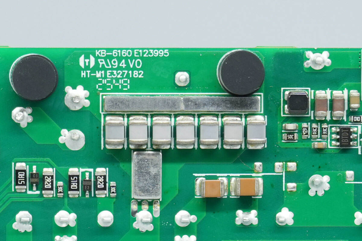
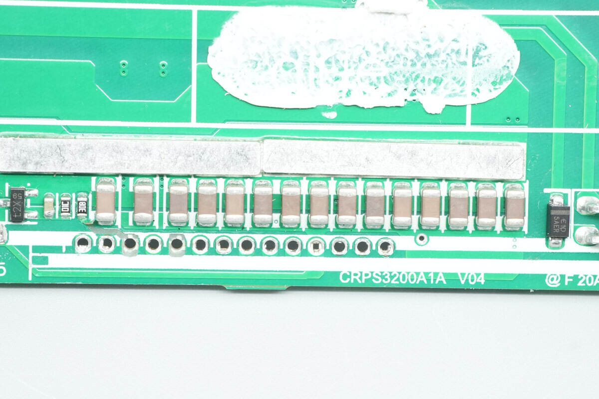
The resonant capacitor is composed of seven NPO capacitors connected in parallel.
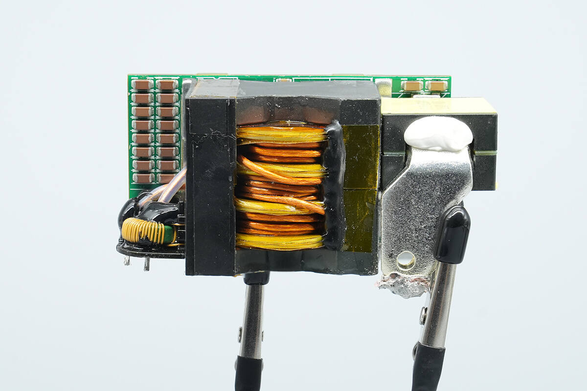
The transformer is soldered onto the synchronous rectification PCB, with a current transformer soldered to its left and a filter inductor soldered to its right.
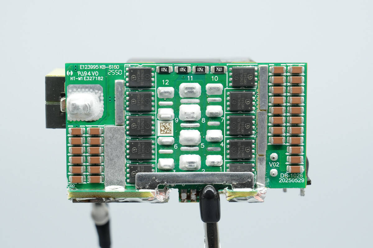
On the back are the synchronous rectifiers and MLCC capacitors.
The bottom of the transformer is fitted with synchronous rectifiers.
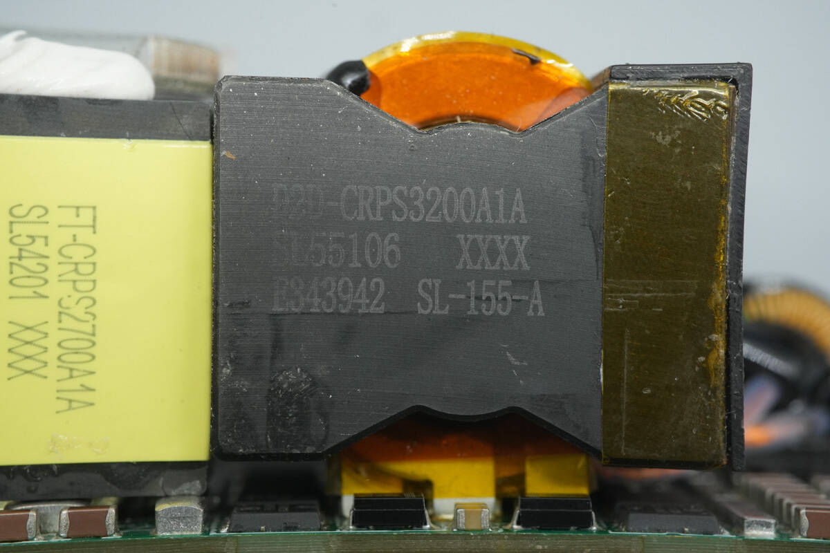
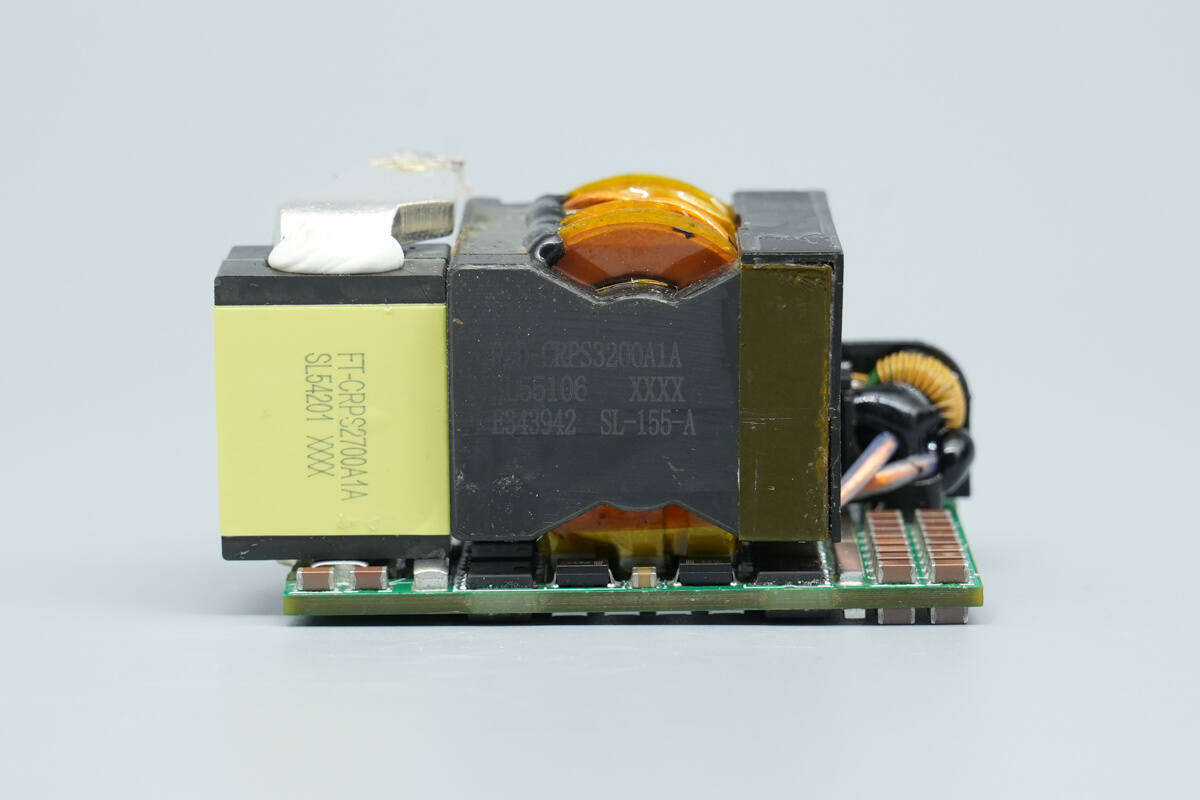
The transformer core is marked with the model D2D‑CRPS3200A1A. On the right side, it has a plastic housing for insulation, and the secondary windings are soldered using copper strips.
Close-up of the synchronous rectifier at the bottom of the transformer.
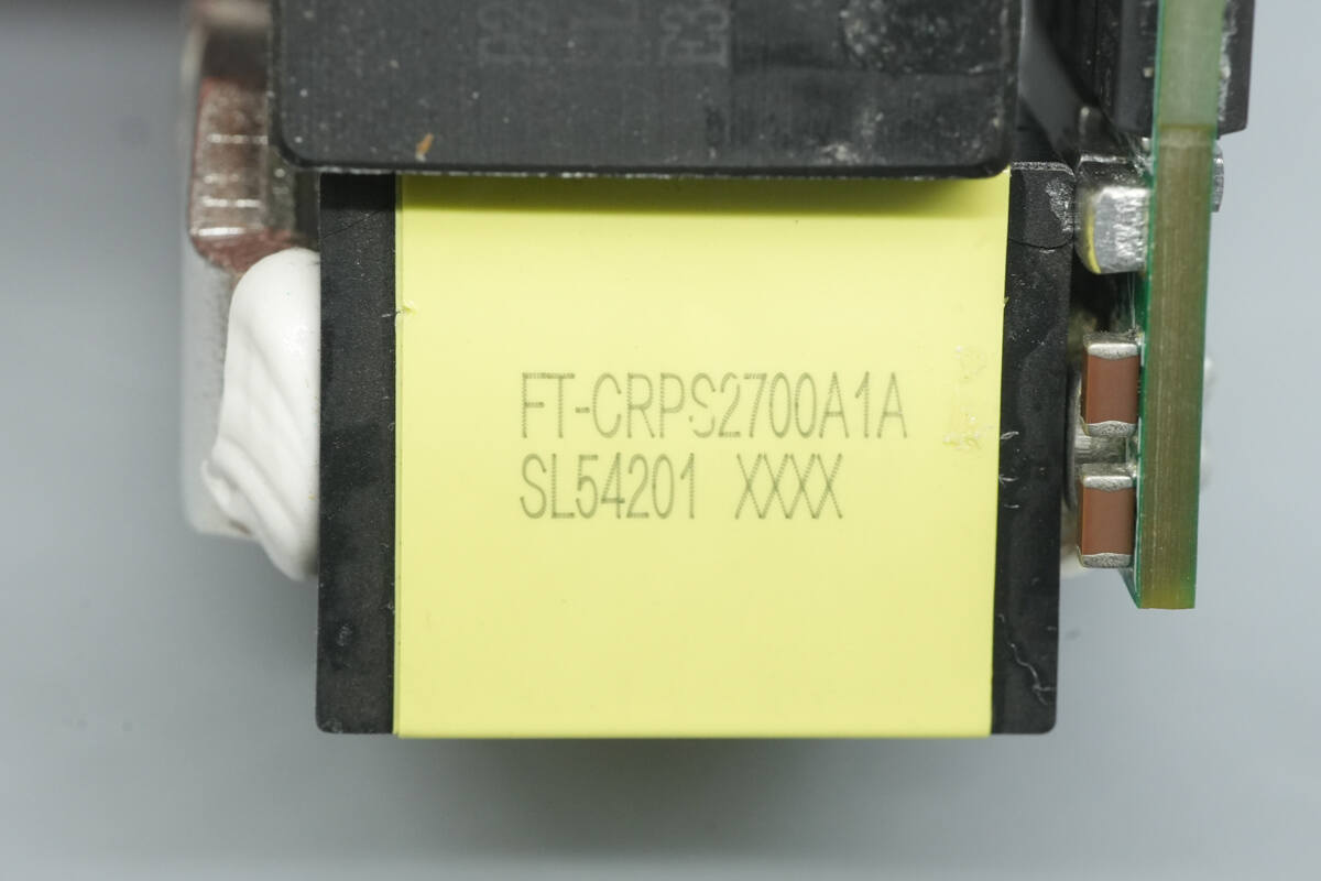
The filter inductor is marked with “FT‑CRPS2700A1A.”
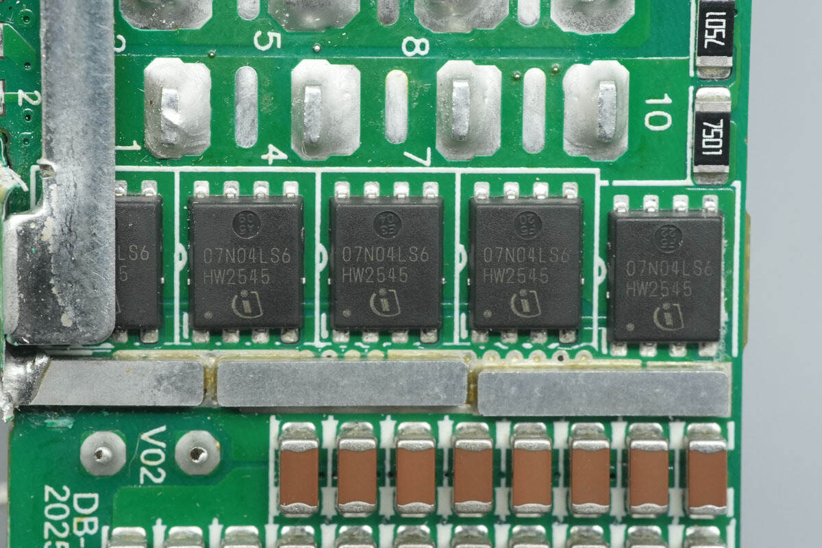
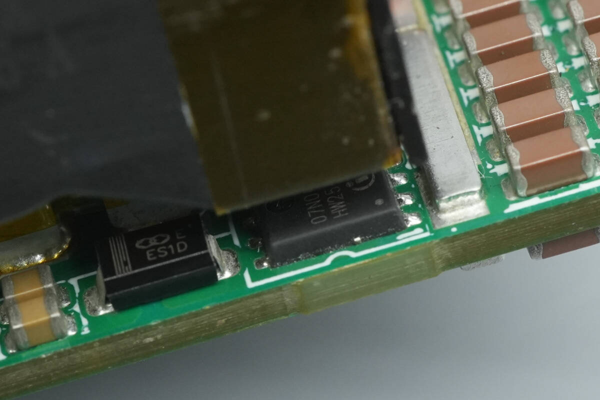
The synchronous rectifiers are from Infineon, marked 07N04LS6, model BSC007N04LS6. They are NMOS devices rated at 40 V with an on-resistance of 0.7 mΩ, and come in a TDSON‑8 package.
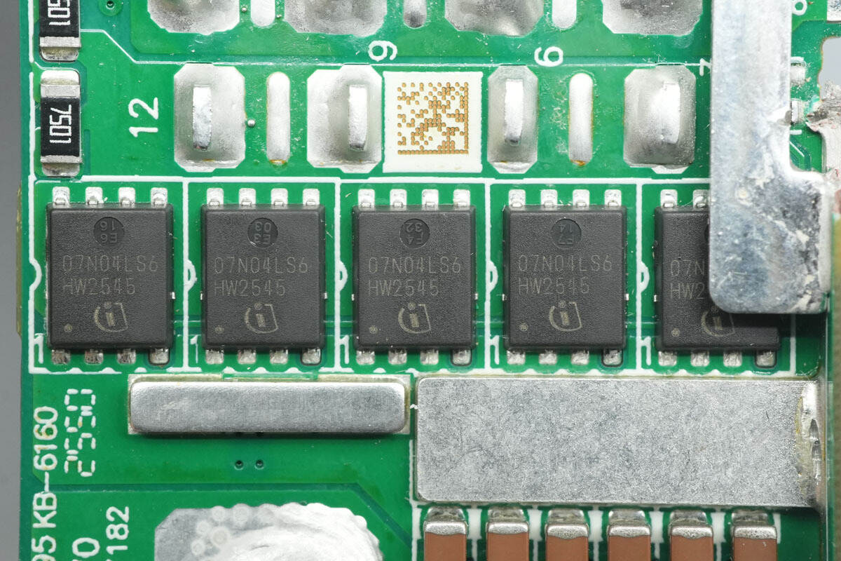
The other set of synchronous rectifiers has the same model.
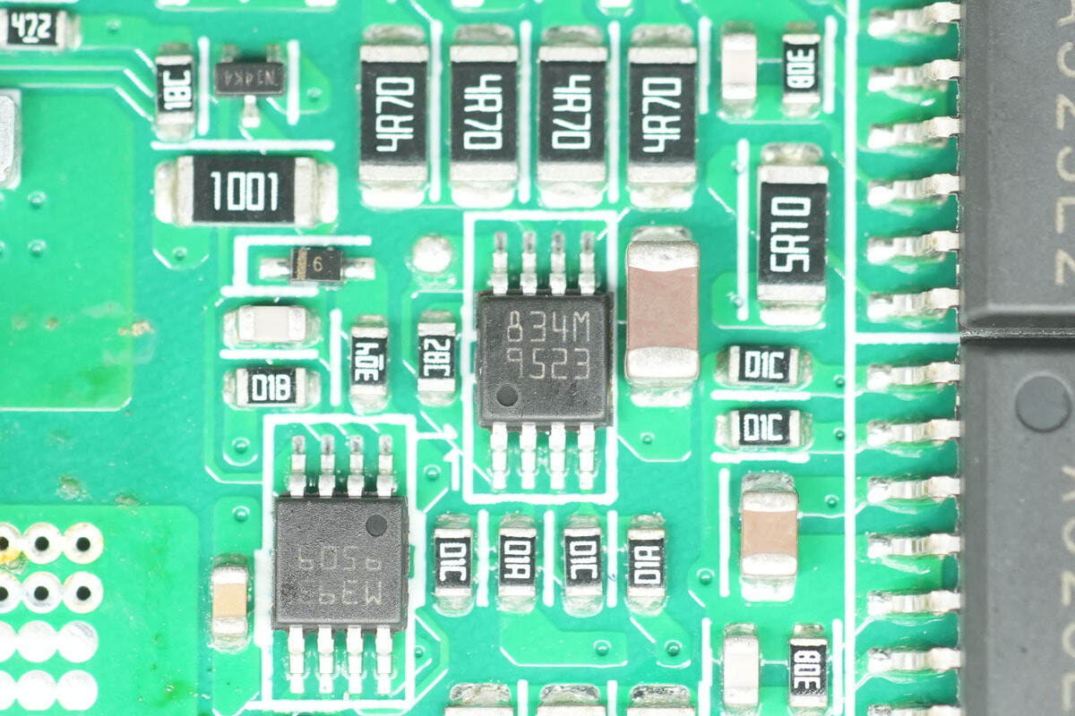
The synchronous rectifier driver is from STMicro, marked 834M, model PM8834M. It is a dual low-side driver with 4 A output capability, and comes in an MSOP8L‑EP package.
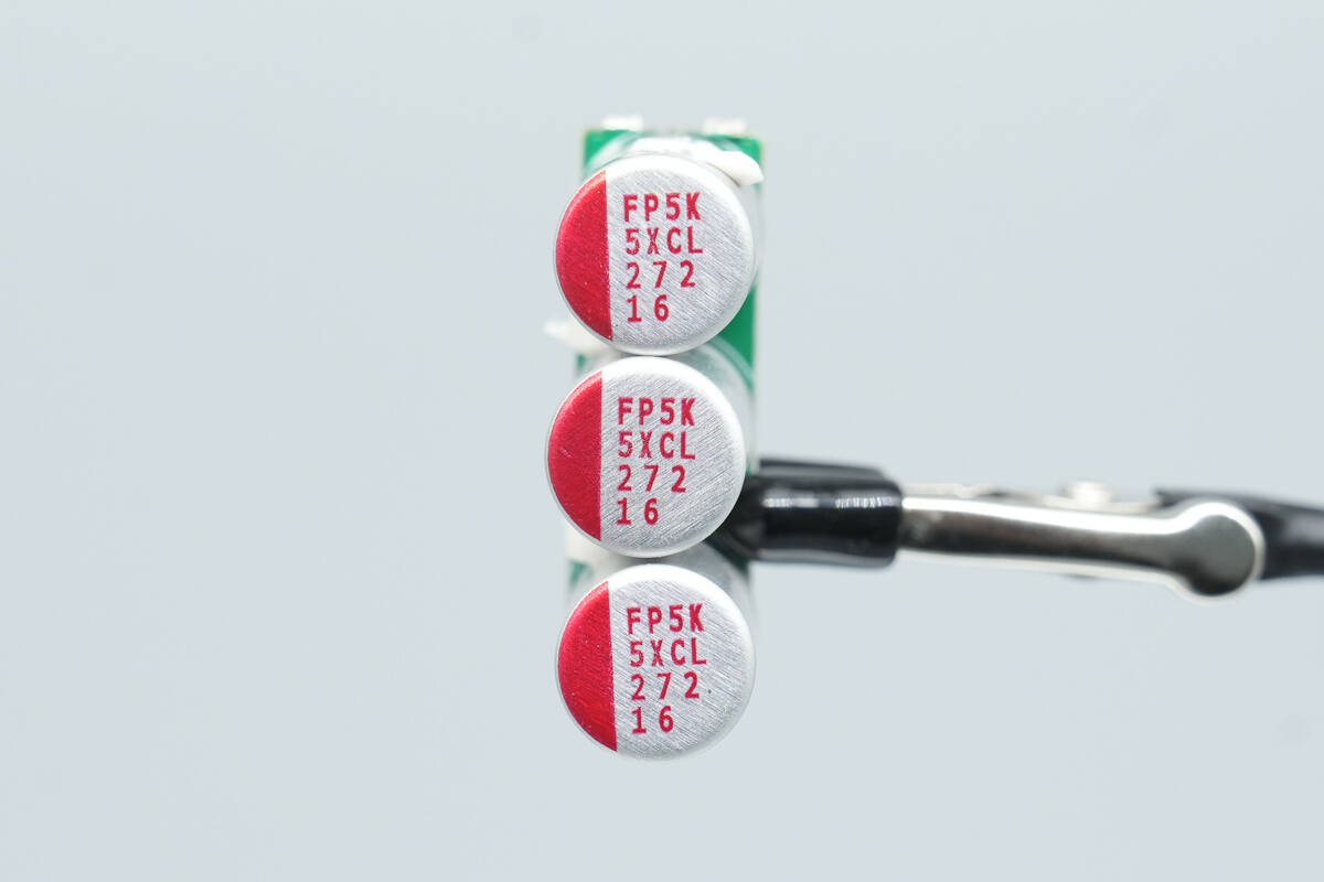
The filter capacitors are from Nichicon, rated 2700 μF, 16 V, with three units connected in parallel.
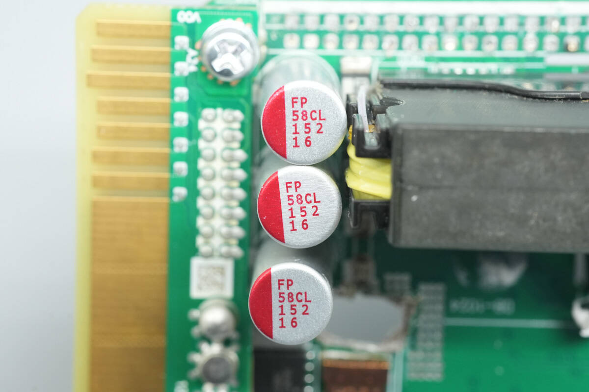
The other set of filter capacitors is rated 1500 μF, 16 V, with three units connected in parallel.
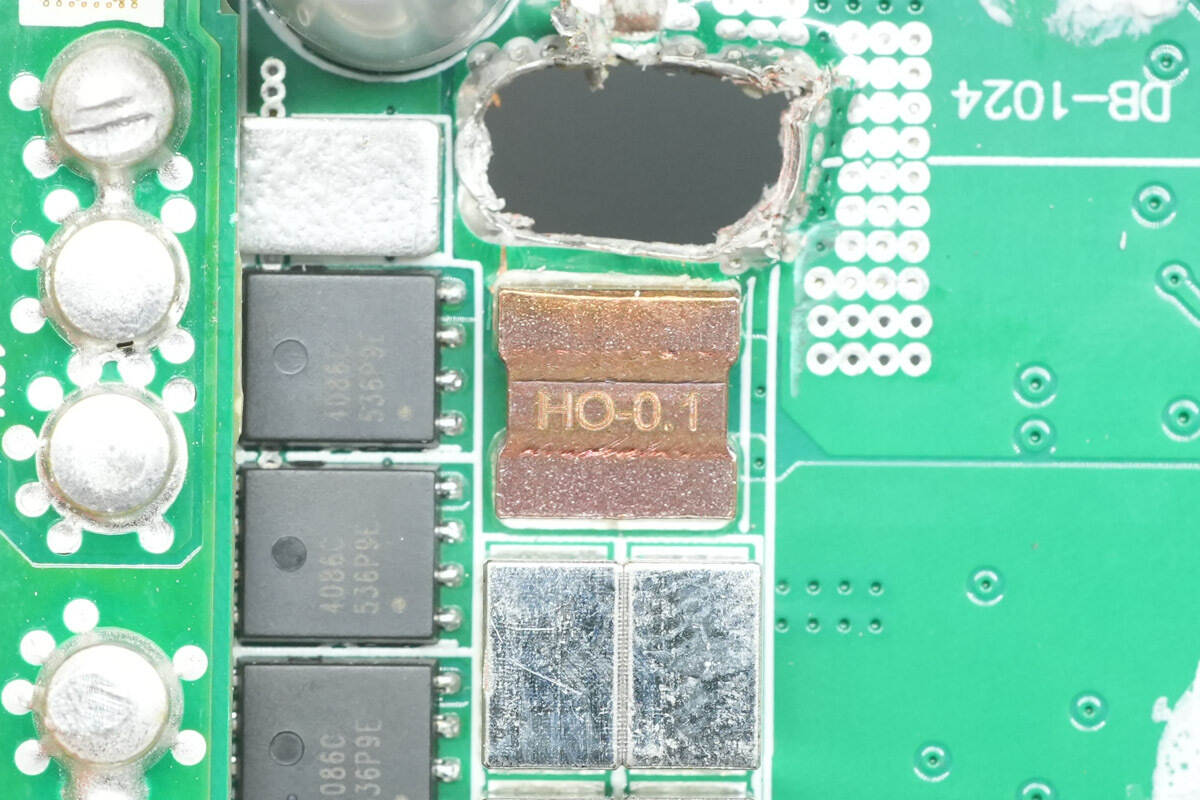
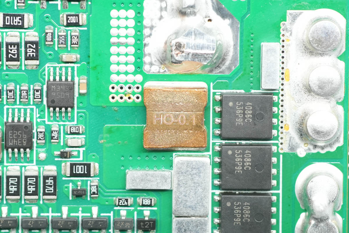
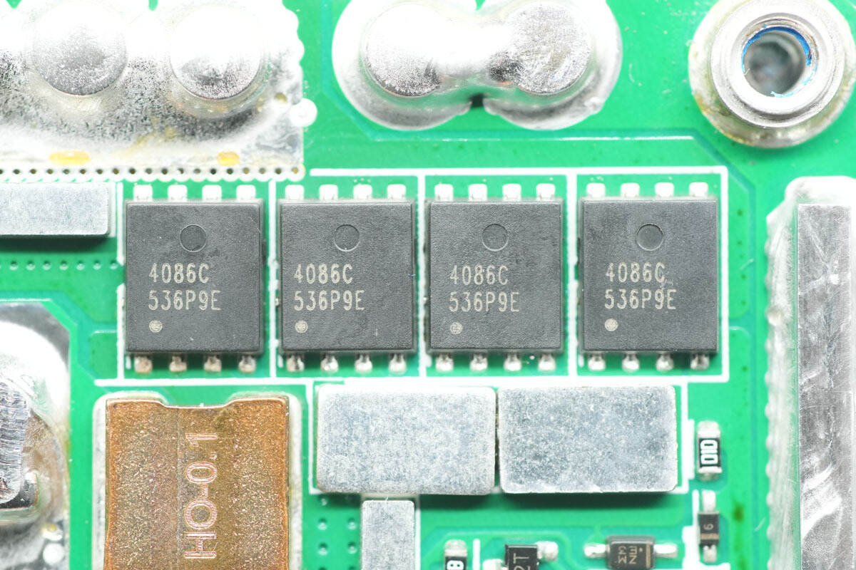
A 0.1 mΩ sense resistor is used for output current detection.
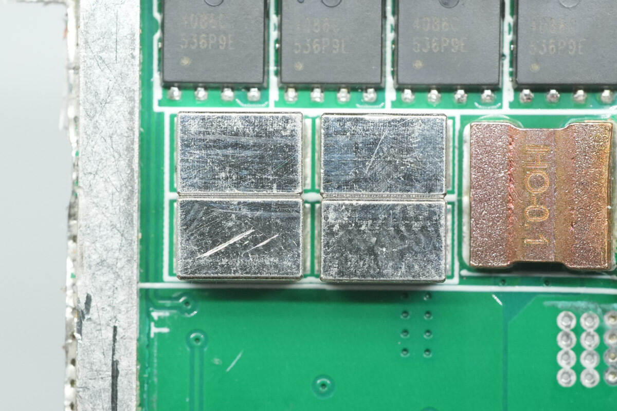
Copper blocks are soldered to the corresponding output control MOSFETs for current sharing.
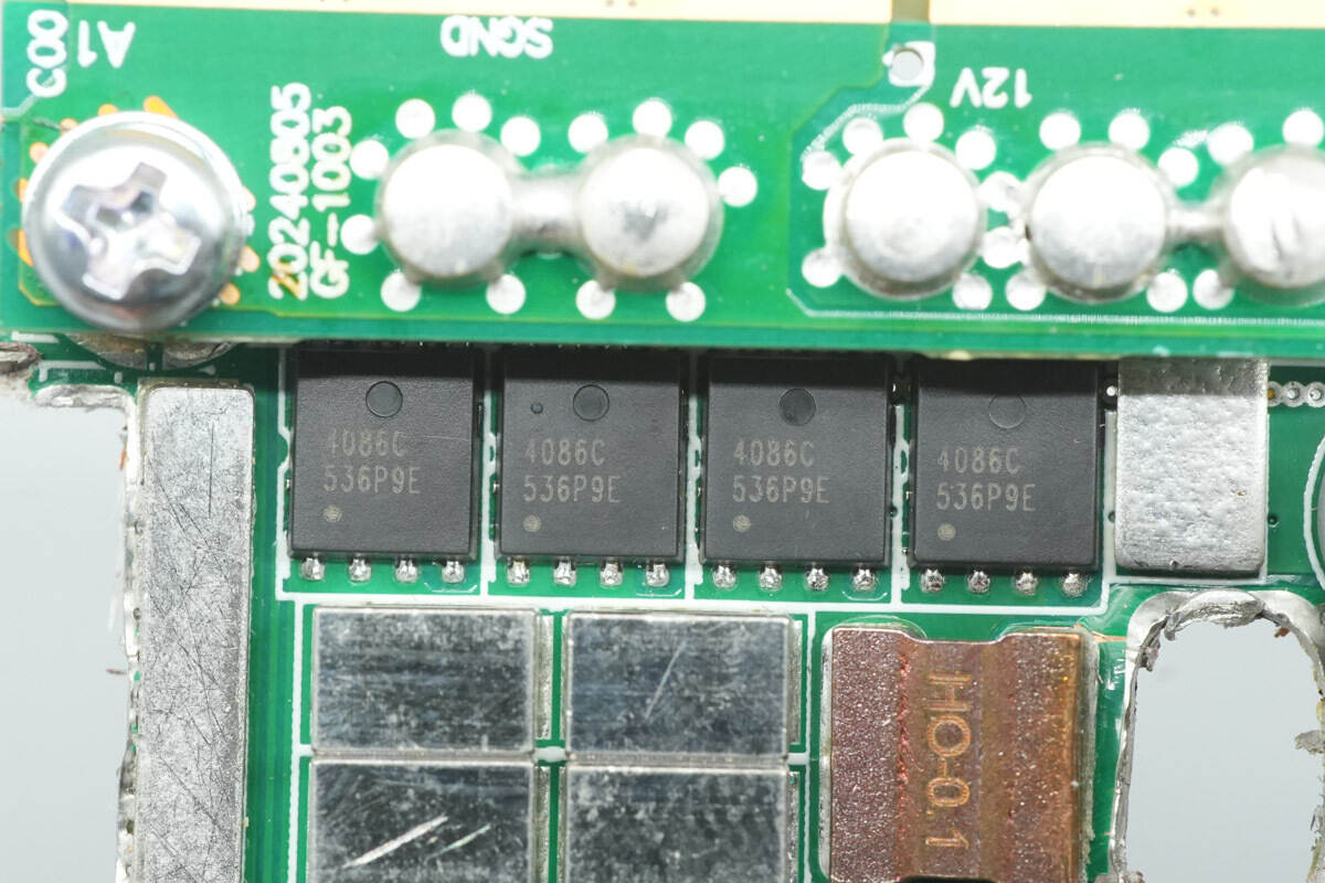
The output control MOSFETs are from APEC, model AP4086CXT. They are NMOS devices rated at 30 V with an on-resistance of 0.58 mΩ, and come in a PMPAK 5×6X package.
The back of the PCB also has 0.1 mΩ sense resistors.
The other output control MOSFETs have the same model.

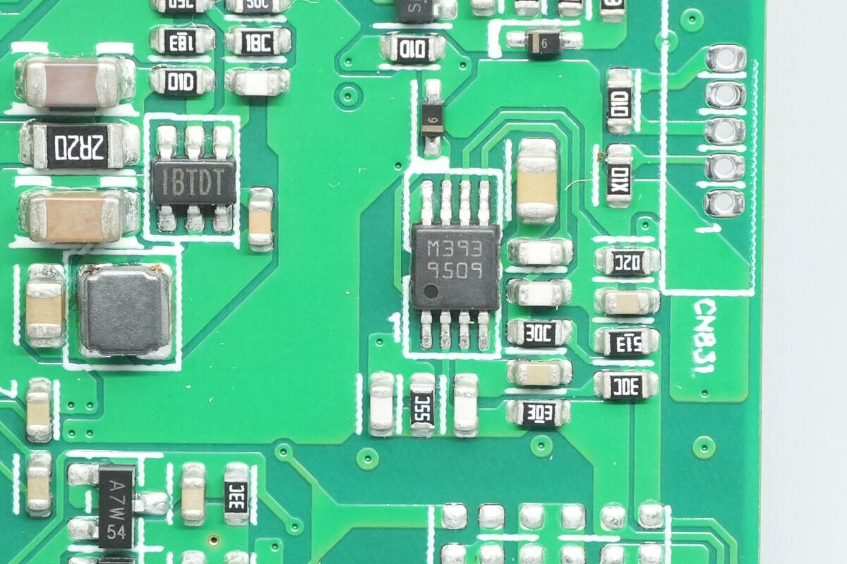
The voltage comparator is from STMicro, marked M393, model LM393ST. It is a low-power dual voltage comparator, packaged in MiniSO8.
The chip marked with IBTD is from MPS.
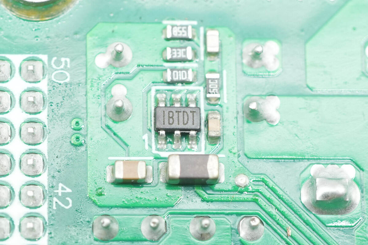
The other chip is marked the same.
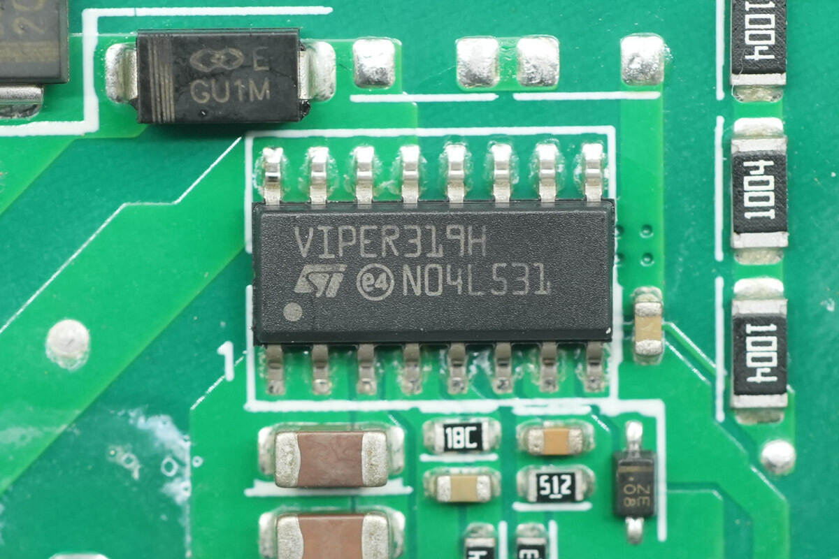
The standby power IC is from STMicro, part of the VIPER31 series, model VIPER319H. It integrates an 800 V MOSFET and high-voltage startup circuitry, uses current-mode control with a switching frequency of 132 kHz, and features overload protection, thermal shutdown, and overvoltage protection. It comes in an SO16N package.
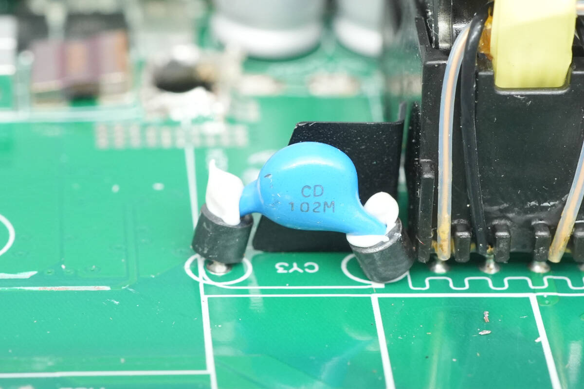
The blue Y capacitor is part number CD102M, with ferrite beads on the leads to suppress high-frequency interference.
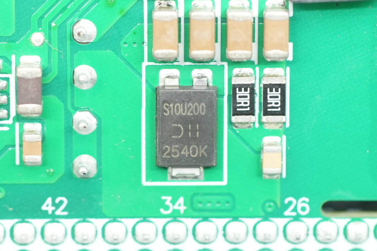
The rectifier is from DIODES, model SBR10U200P5. It is a Super Barrier Rectifier (SBR) rated at 200 V, 10 A, and comes in a PowerDI5 package.
Remove the control PCB, revealing MLCC capacitors on the inner side of the PCB.
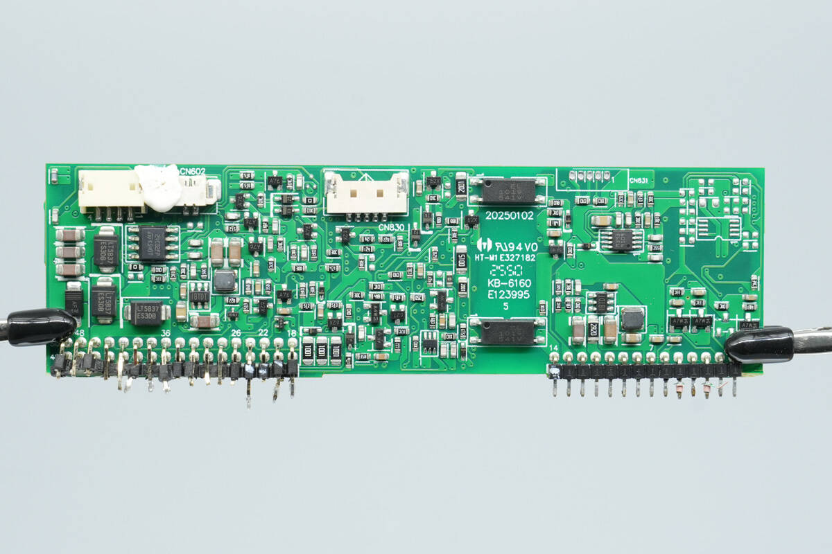
On the other side are components including a voltage comparator, operational amplifier, optocoupler, memory chip, and diodes.
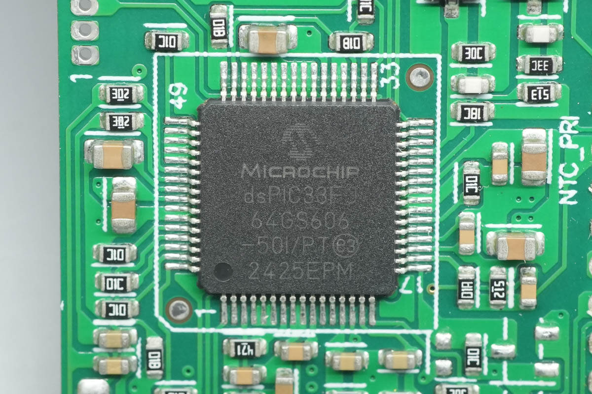
The PFC controller is from Microchip, featuring a built-in 16-bit DSPIC33F CPU, 64 KB of Flash, and 9 KB of RAM. It is used for switching power supply and synchronous rectification control, and comes in a TQFP64 package.
The voltage comparator is an LM393ST from STMicro.

The buck chip is marked IBTDT.
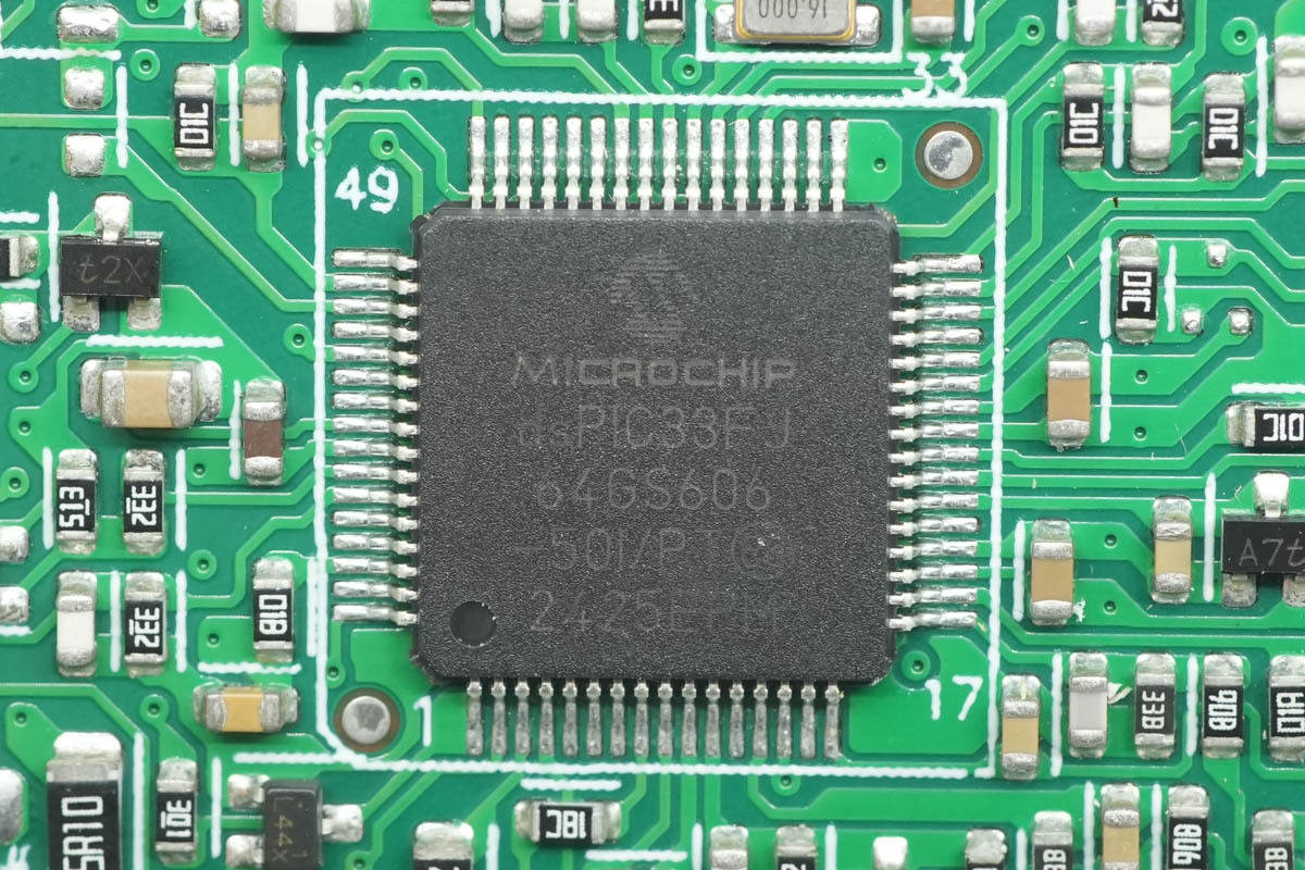
The full-bridge LLC controller uses a Microchip DSPIC33F CPU.
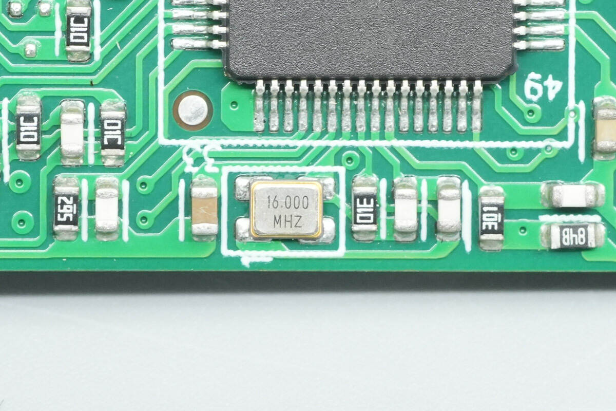
The chip is paired with an external 16.000 MHz crystal oscillator.
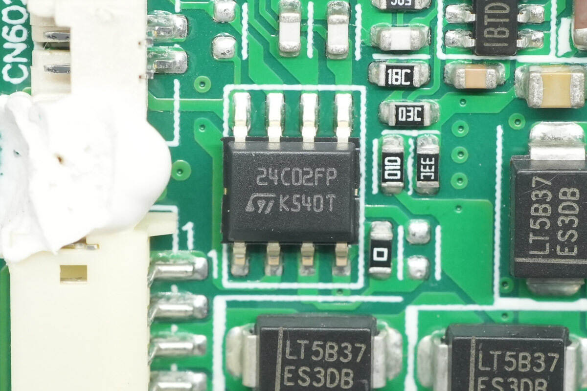
The memory is from STMicro, model M24C02-F, with a capacity of 256 bytes. It supports an operating voltage of 1.7–5.5 V and comes in an SO8N package.
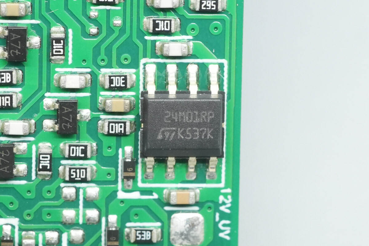
The other memory chip is model M24M01-R, with a capacity of 128 KB. It supports an operating voltage of 1.7–5.5 V and comes in an SO8 package.
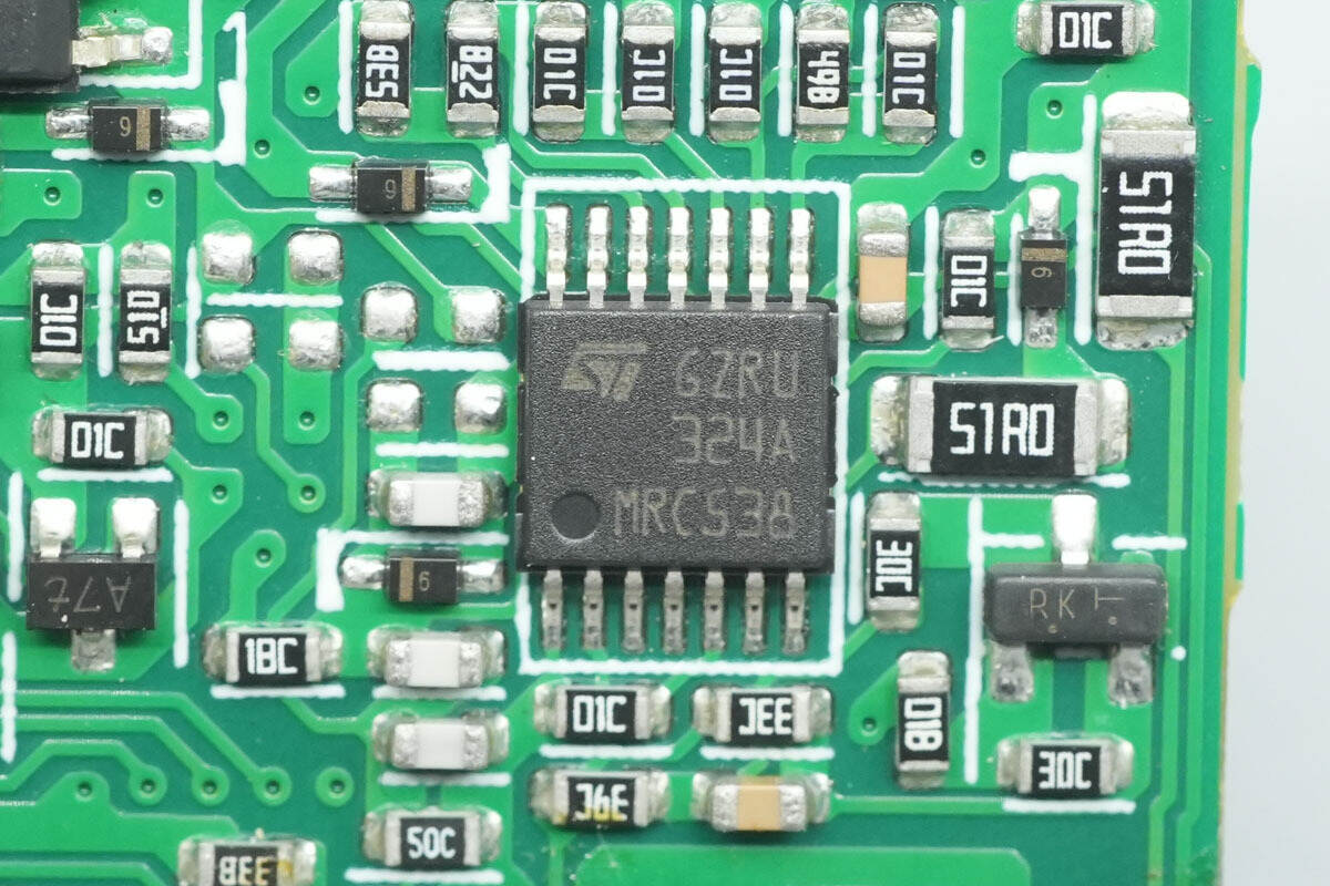
The operational amplifier is from STMicro, model LM324A. It is a low-power, low-input-bias-current quad op-amp, and comes in a TSSOP14 package.
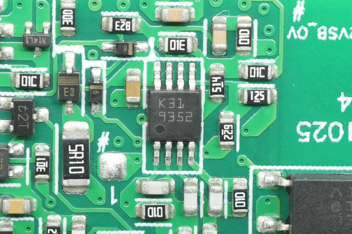
The dual operational amplifier is from STMicro, marked K31, model TSB572IST. It is a low-power 36 V BiCMOS op-amp and comes in a MiniSO8 package.
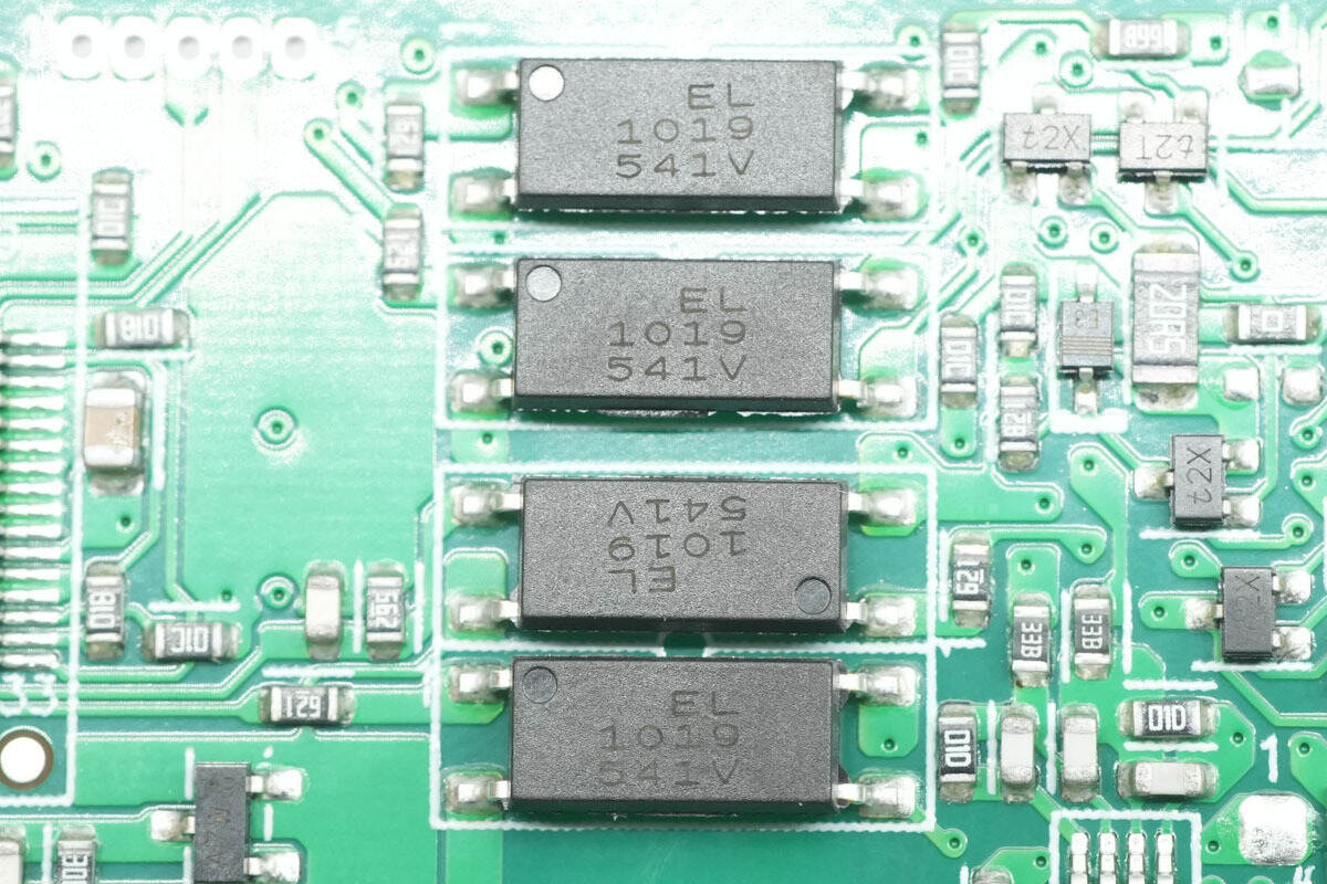
The optocouplers are from Everlight, model EL1019, used for isolation communication between the primary and secondary sides.

On the other side of the PCB is another optocoupler of the same model.
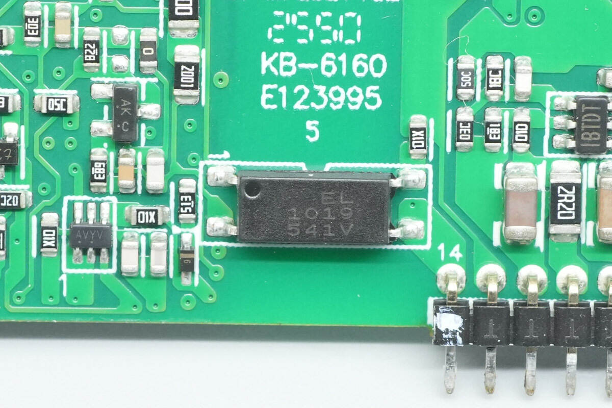
Close-up of the Everlight EL1019 optocoupler.
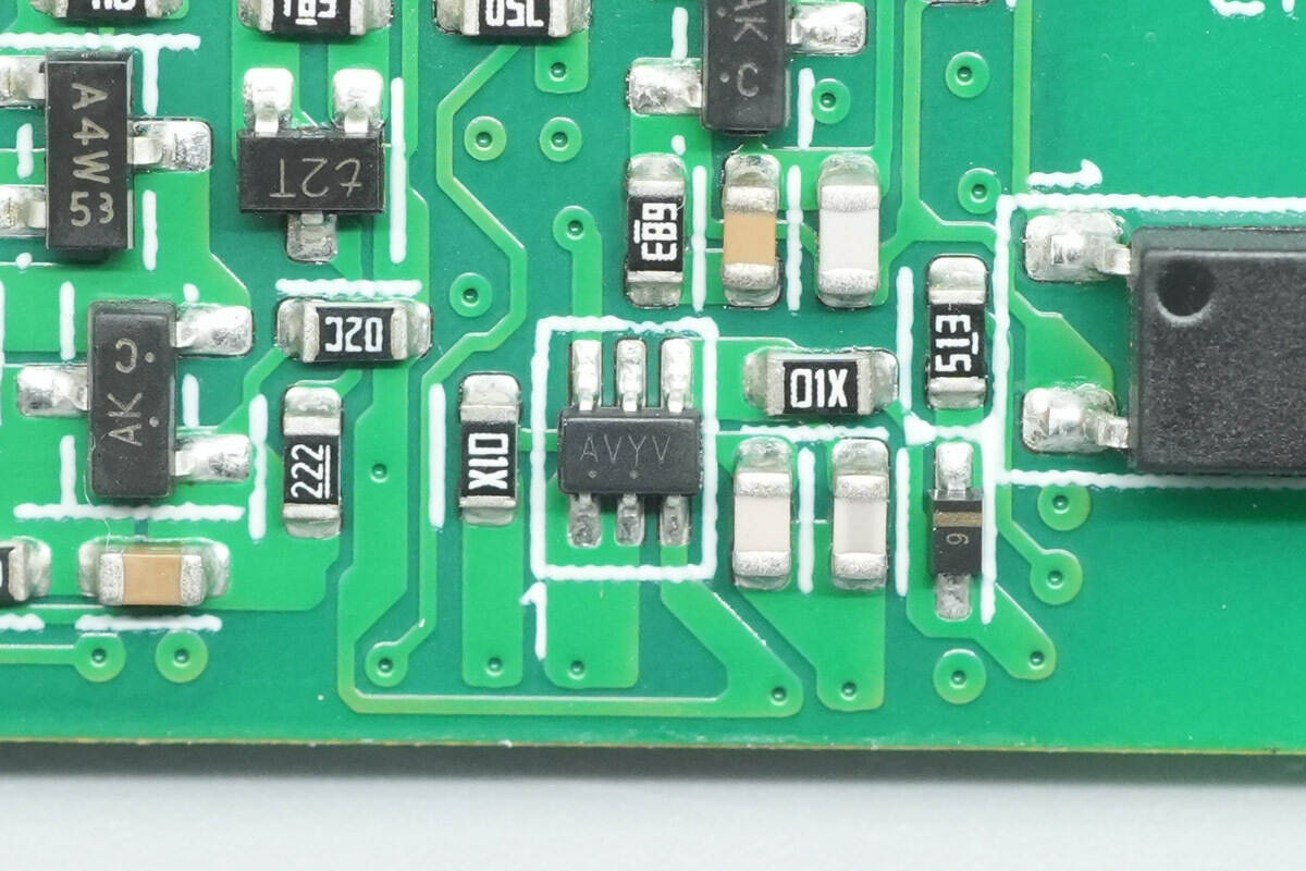
Close-up of the chip marked AVYV.

The buck chip is marked IBTD.
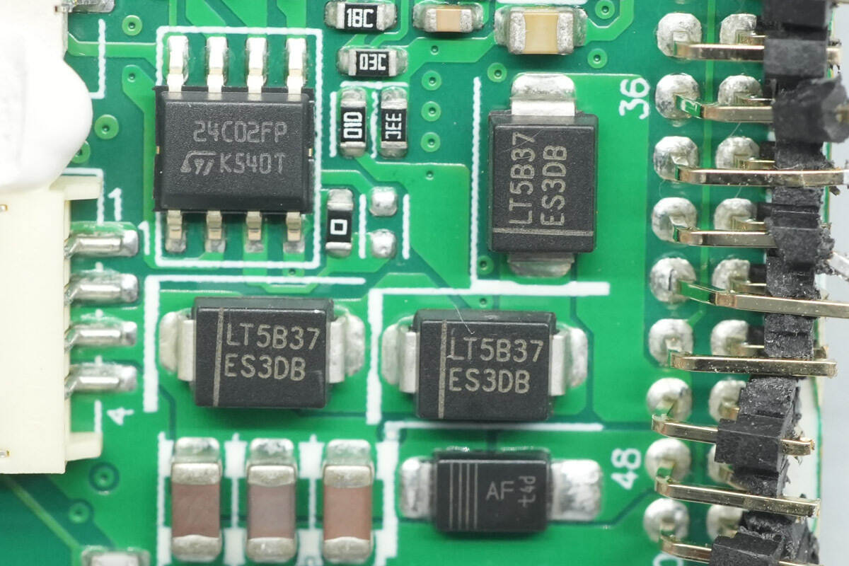
Close-up of the three ES3DB diodes.
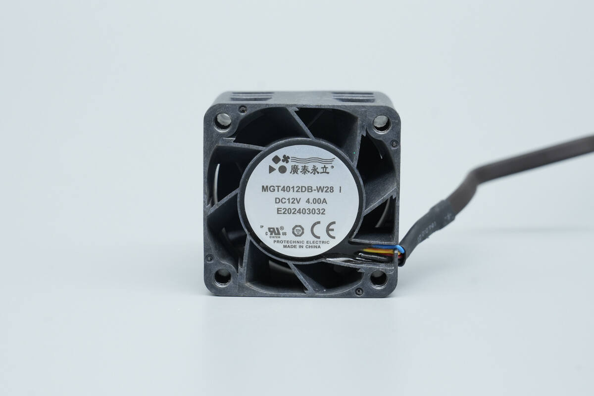
The cooling fan is model MGT4012DB‑W28, rated at 12 V, 4 A, and is equipped with static blades.

Well, those are all components of the Aohai Technology 3200W 80 PLUS Titanium Server Power Supply.
Summary of ChargerLAB
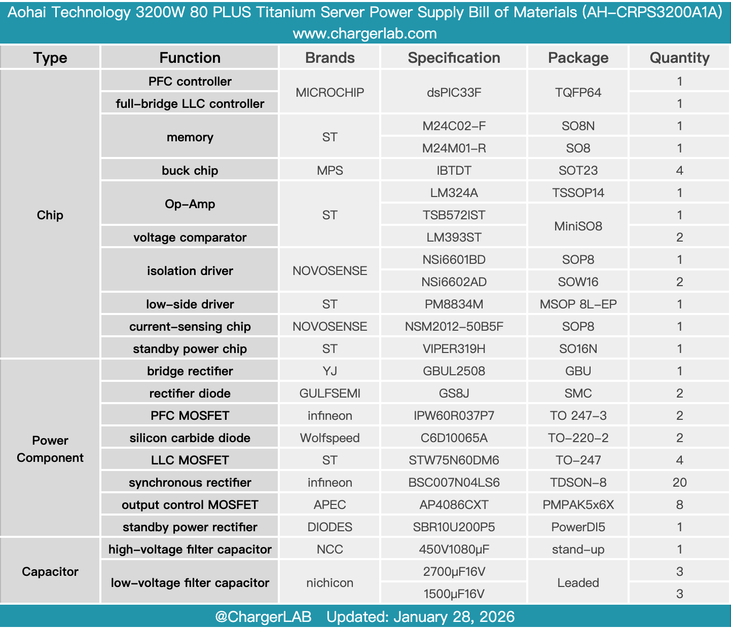
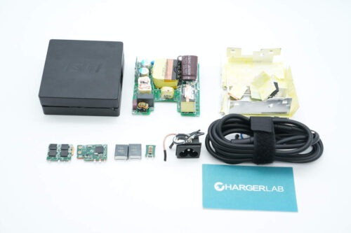
Here is the component list of the Aohai Technology 3200W 80 PLUS Titanium Server Power Supply for your convenience.
The power supply, model AH‑CRPS3200A1A, supports 100–240 V AC input and 240 V DC input. Its main output is rated at 12 V, 262.3 A, with a total power of 3200 W. The standby output provides 12 V at 2.1 A. Internally, the power supply is equipped with a cooling fan that draws air from the DC output side and expels it through the AC input side.
After taking it apart, we found that it uses a Microchip control scheme, with two dsPIC33F controllers dedicated to PFC and LLC control, respectively. The PFC MOSFETs are Infineon IPW60R037P7 devices, driven by NOVOSENSE NSi6601BD isolation drivers. The PFC rectifiers are Wolfspeed C6D10065A silicon carbide diodes.
The LLC MOSFETs are STMicro STW75N60DM6, driven by NOVOSENSE NSi6602AD isolation drivers. The synchronous rectifiers are Infineon BSC007N04LS6 devices, driven by STMicro PM8834M drivers. The standby power IC is STMicro VIPER319H. High-voltage capacitors are from NCC, and the output filter capacitors are from Nichicon. All components are from leading international brands, reflecting solid build quality and robust material selection.
Related Articles:
1. Teardown of CUKTECH 6 90W Mini GaN Charger (AD653)
2. Teardown of Xiaomi 140W 8-in-1 Desktop Charging Station (XMCDZ-03QM)
3. Teardown of HONOR SuperCharge 66W Power Adapter (HN-110600CP0)