Introduction
We recently obtained an AcBel 1100W Platinum Server Power Supply. This power supply supports an input voltage range of 100–127V, delivering an output power of 1050W under these conditions. When the input voltage is between 200 and 240V, it achieves its rated output power of 1100W. The power supply’s rated output voltage is 12.2V, with an auxiliary output of 12V and a rated output current of 3A.
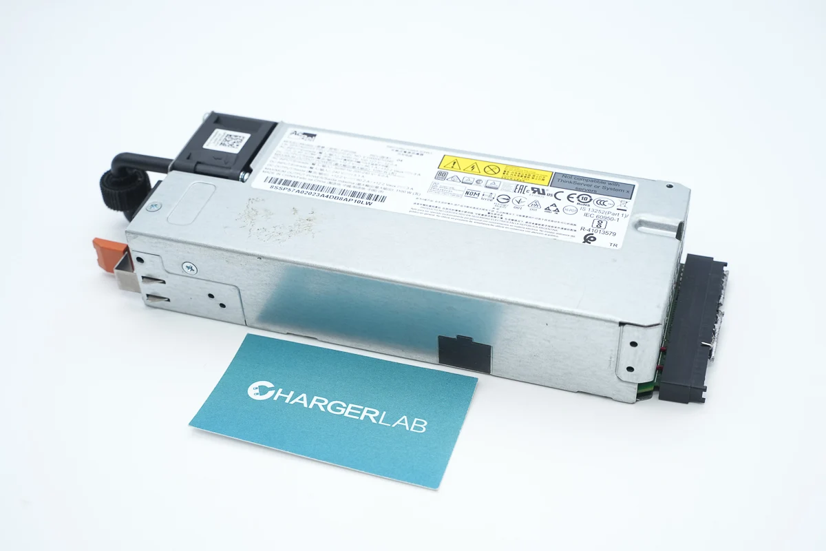
The power supply module features a long rectangular metal casing, with a cooling fan, handle, indicator light, and power socket on the input side, and a gold finger connector on the output side. This power supply module is designed to provide power for Lenovo servers and adopts a PFC plus phase-shift full-bridge architecture. Next, we present the teardown to take a closer look at its internal design and components.
Product Appearance
The metal casing is fixed by stamping and screws.

A nameplate is attached to the front side.
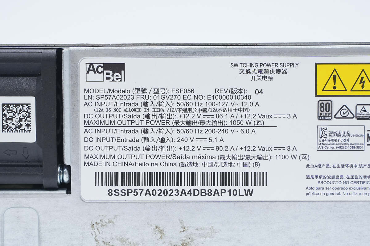
Model: FSF056
Input: 50/60Hz 100-127V\~ 12A
Output: +12.2V 86.1A / +12.2Vaux 3A
Maximum Output: 1050W
Input: 50/60Hz 200-240V\~ 6A
Input: 240V 5.1A
Output: +12.2V 90.2A / +12.2Vaux 3A
Maximum Output: 1100W
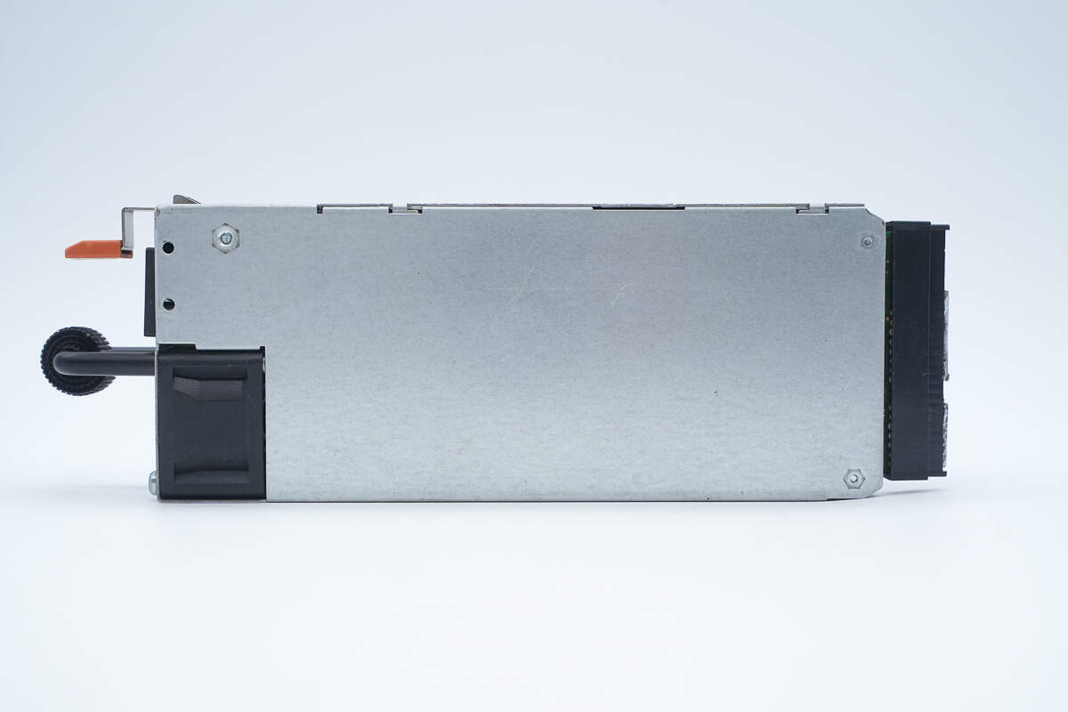
There are mounting screw holes on the back.

There are also mounting screw holes on the side.

The input side is equipped with a handle, a cooling fan, indicator lights, a C14 inlet, and a trip handle.
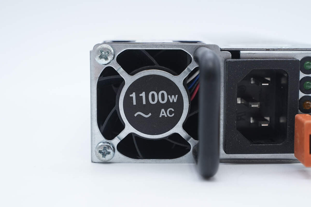
The protective cover of the cooling fan is labeled with a power output of 1100W.
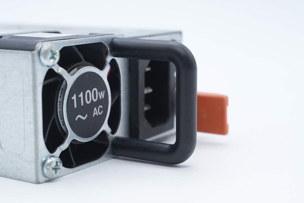
The handle is used to pull out the power module.
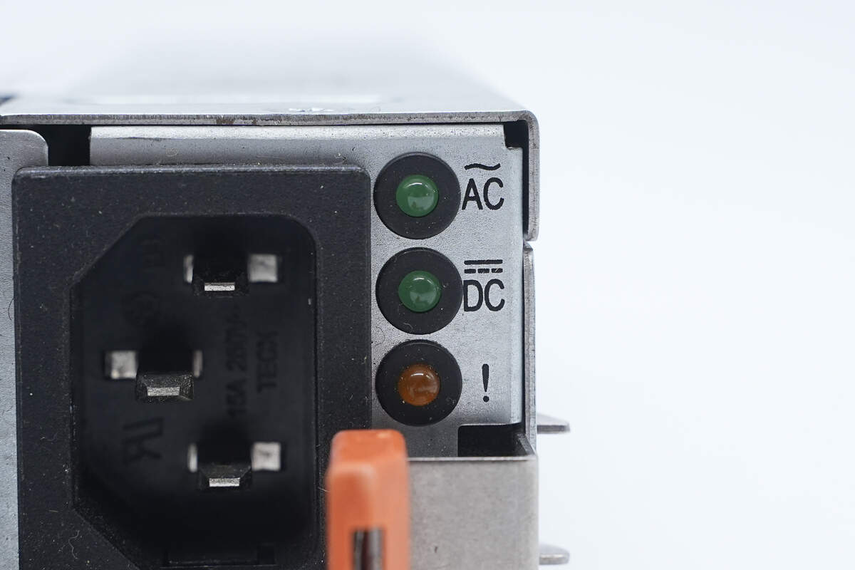
Close-up of the LED indicator lights.
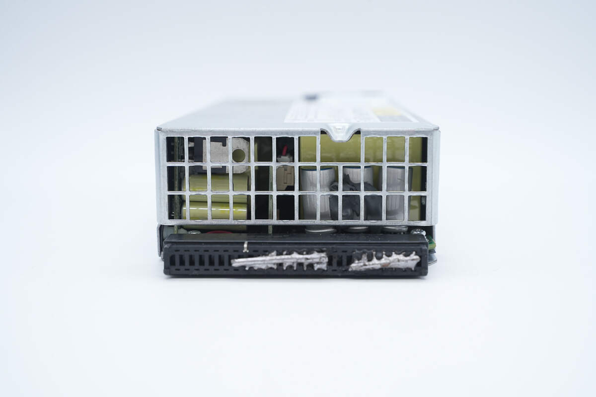
The output side is equipped with a grille and a connector.

The length is about 212 mm (8.35 inches).
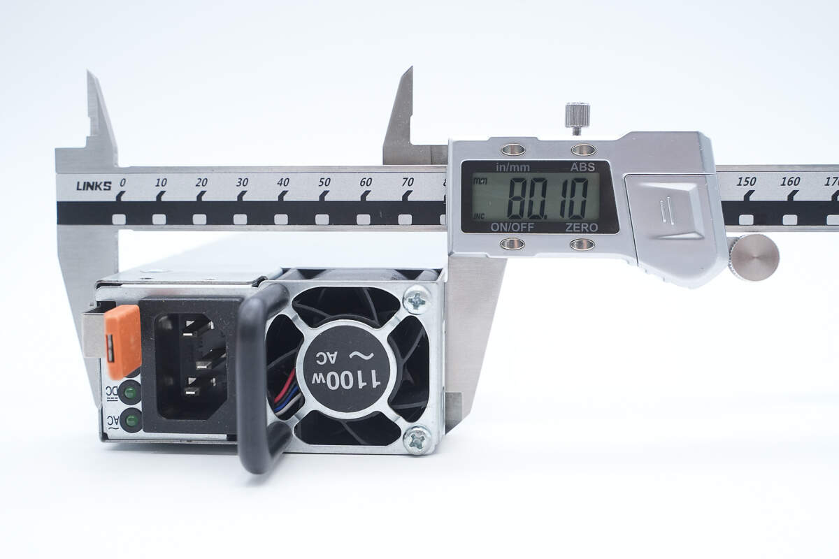
The width is about 80.1 mm (3.15 inches).
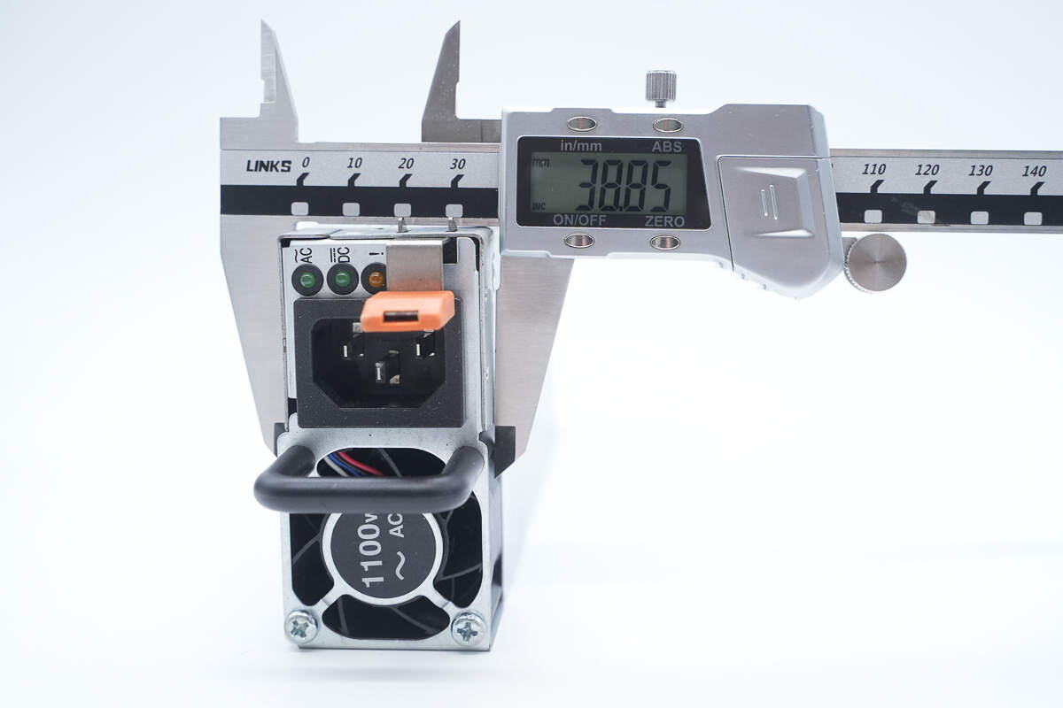
The thickness is about 38.9 mm (1.53 inches).
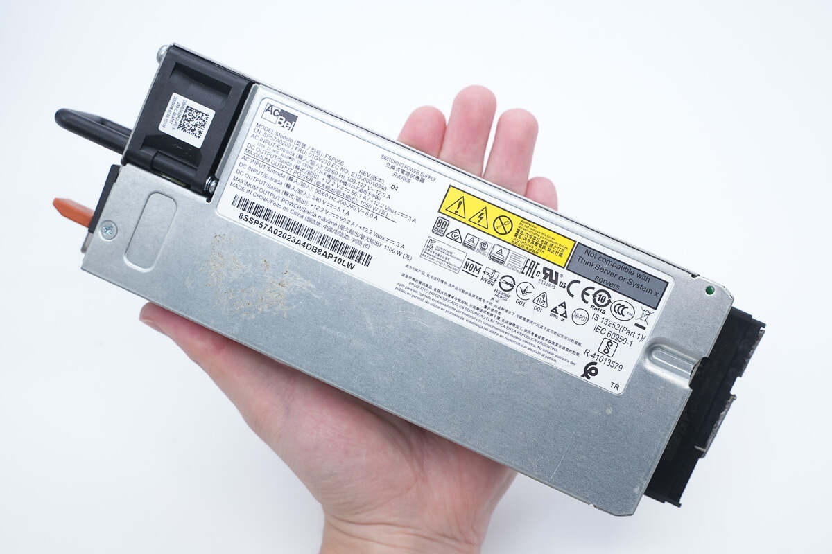
That's how big it is in the hand.
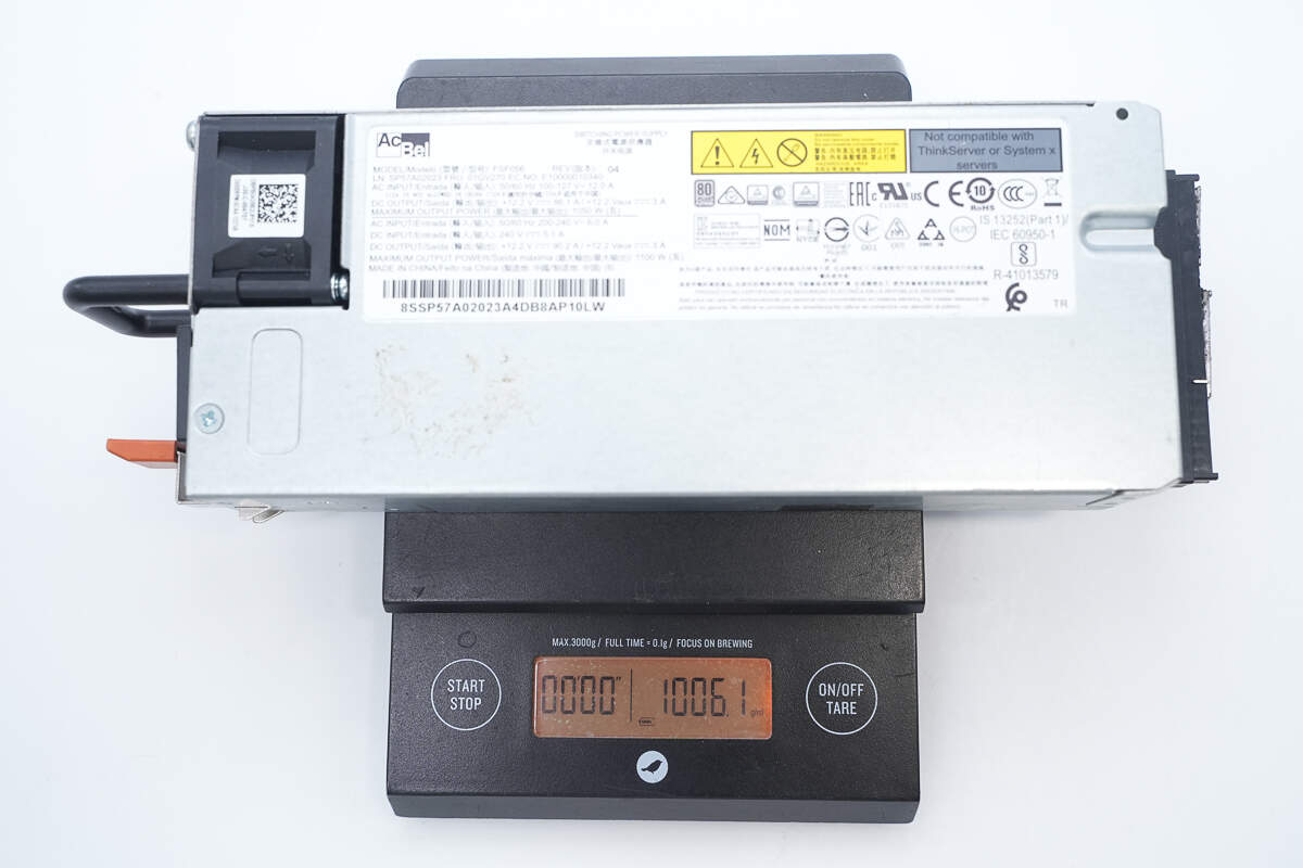
The weight is about 1006 g (35.49 oz).
Teardown
Next, let's take it apart to see its internal components and structure.
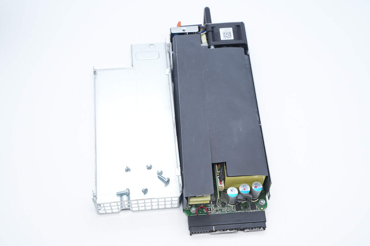
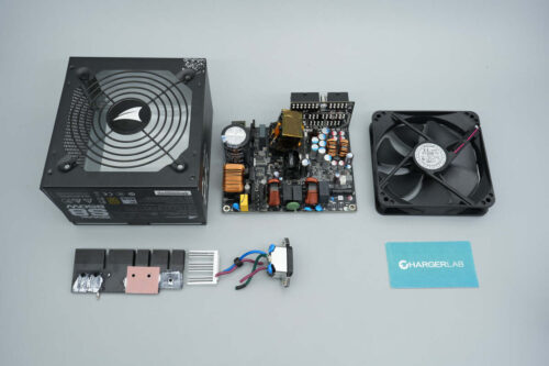
Unscrew the fixing screws and remove the casing.

The PCBA module is wrapped in a black Mylar sheet for insulation.

The PCBA module is fixed inside the housing with screws.
The PCBA module is secured inside the casing with screws.

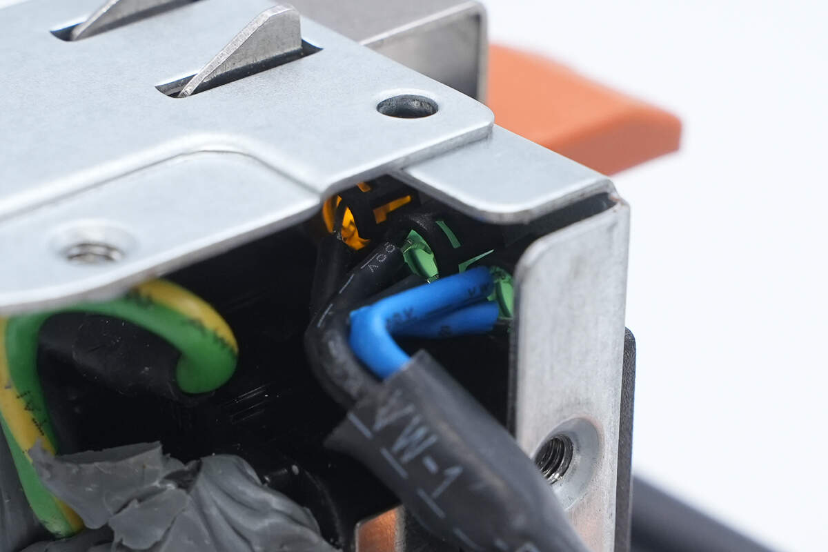
The wires for the indicator light and cooling fan are connected via plug-in connectors.
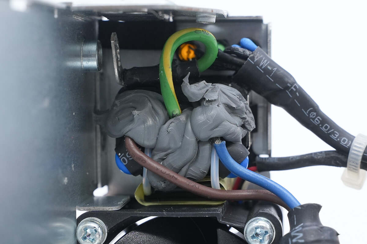
The power socket is insulated with adhesive sealing.
The pins of the indicator lights are insulated with heat-shrink tubing.
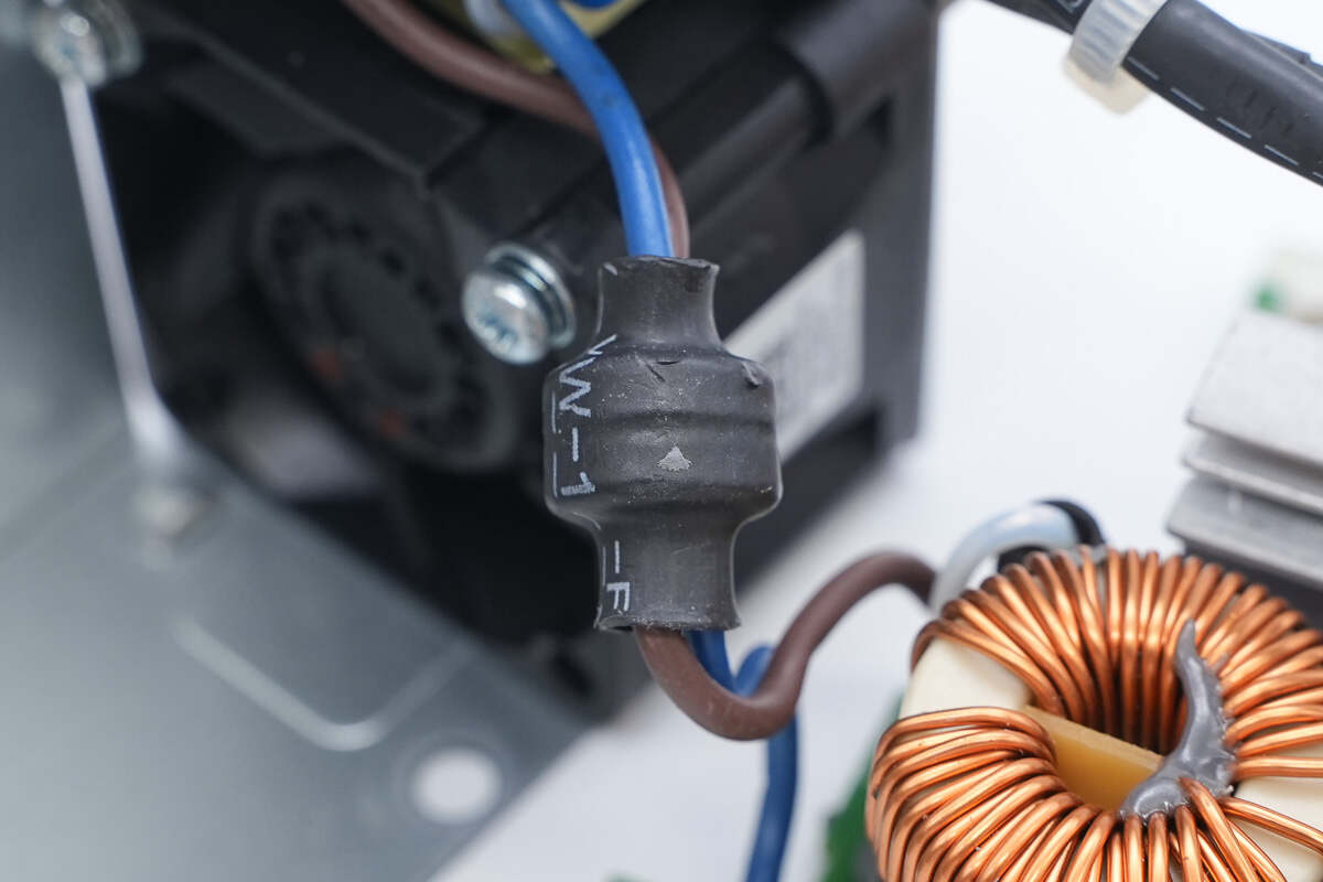
The power cable is equipped with a ferrite core to suppress high-frequency interference.
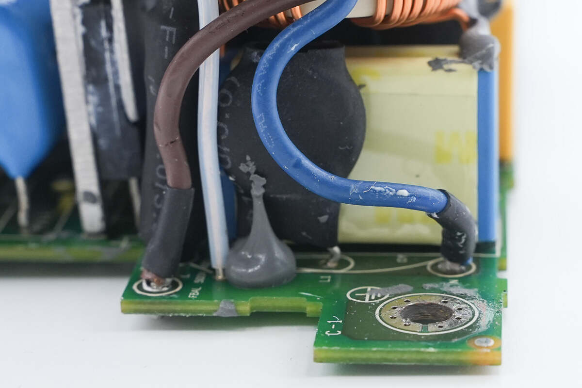
The power cable’s crimp terminals are soldered to the PCBA module, with heat shrink tubing applied for insulation.
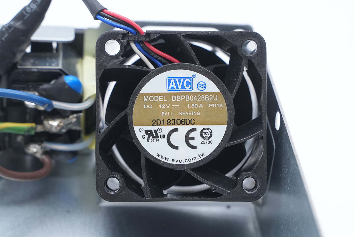
The cooling fan is manufactured by AVC, model DBPB0428B2U, with specifications of 12V and 1.8A.
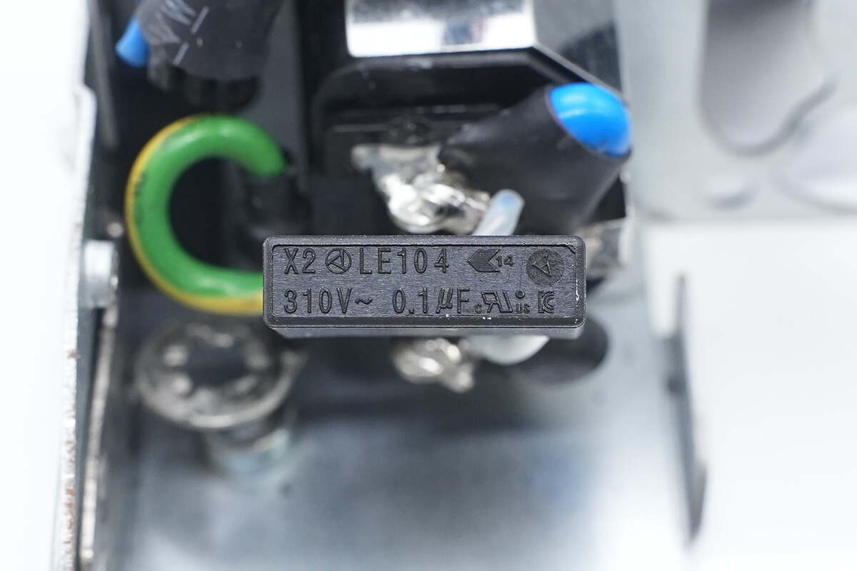
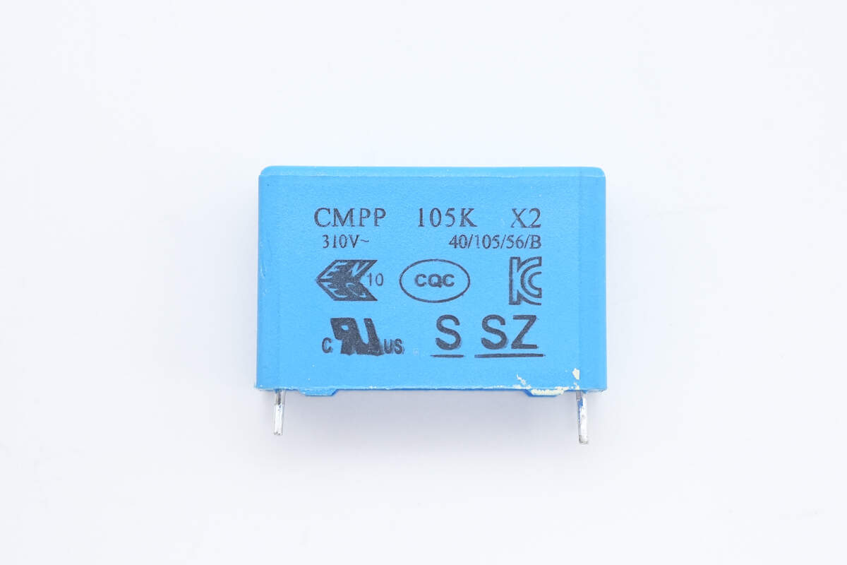
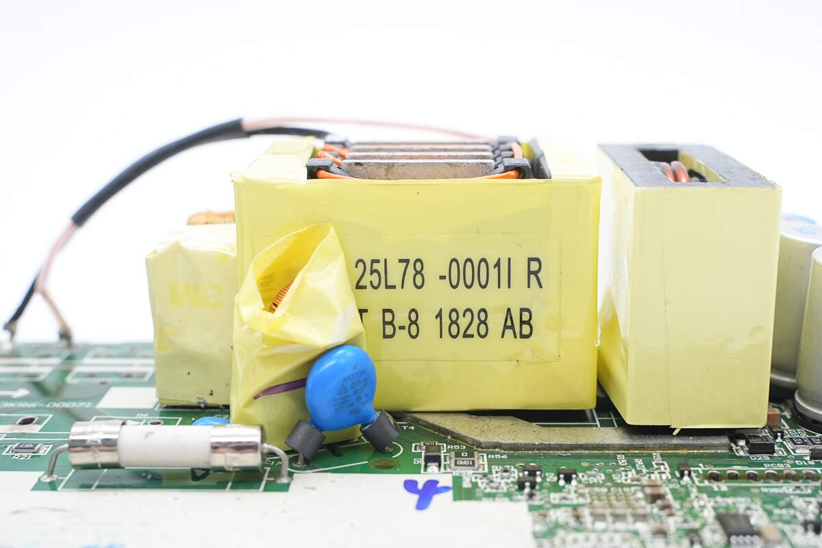
The safety X2 capacitor is rated at 0.1 μF.
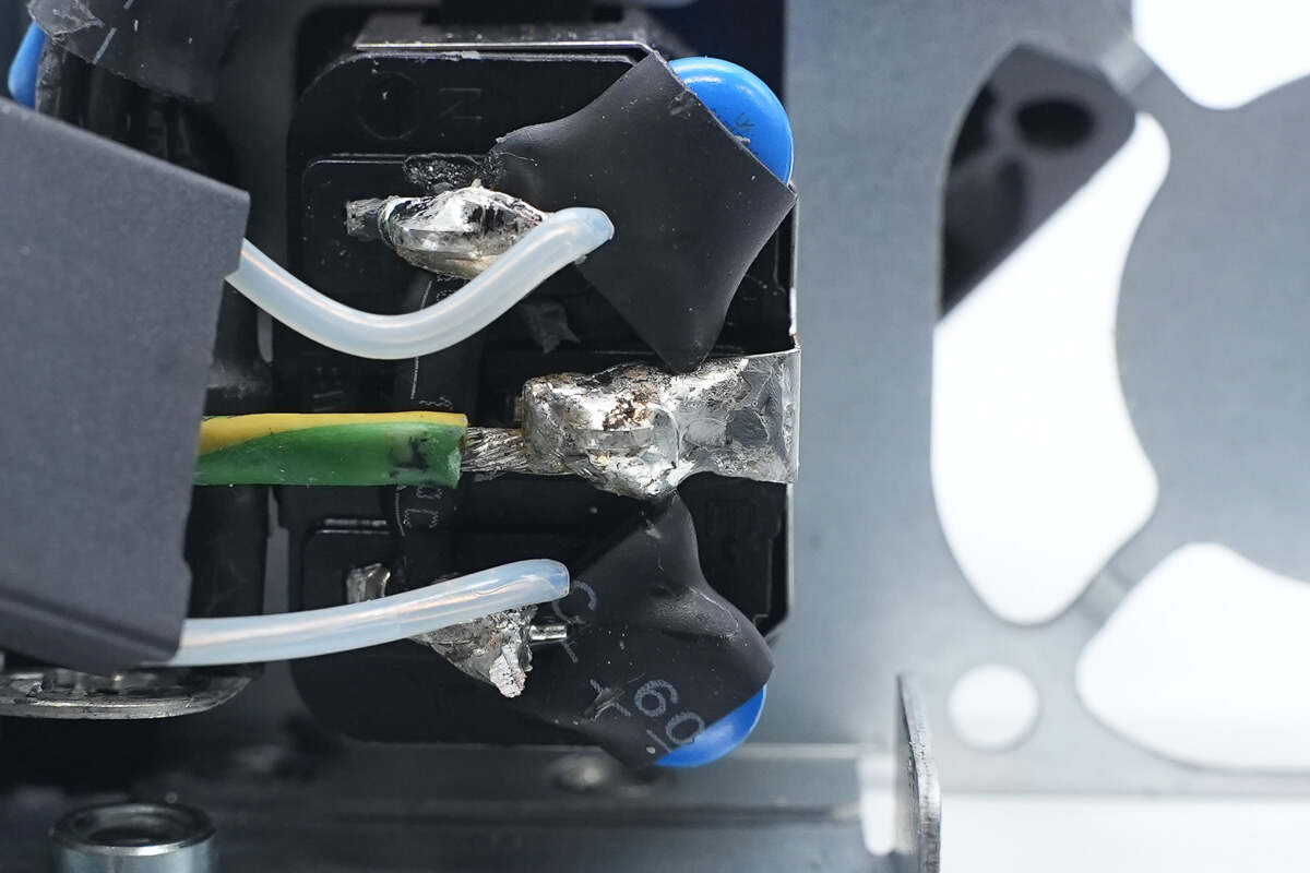
The blue Y capacitors are connected by soldering.

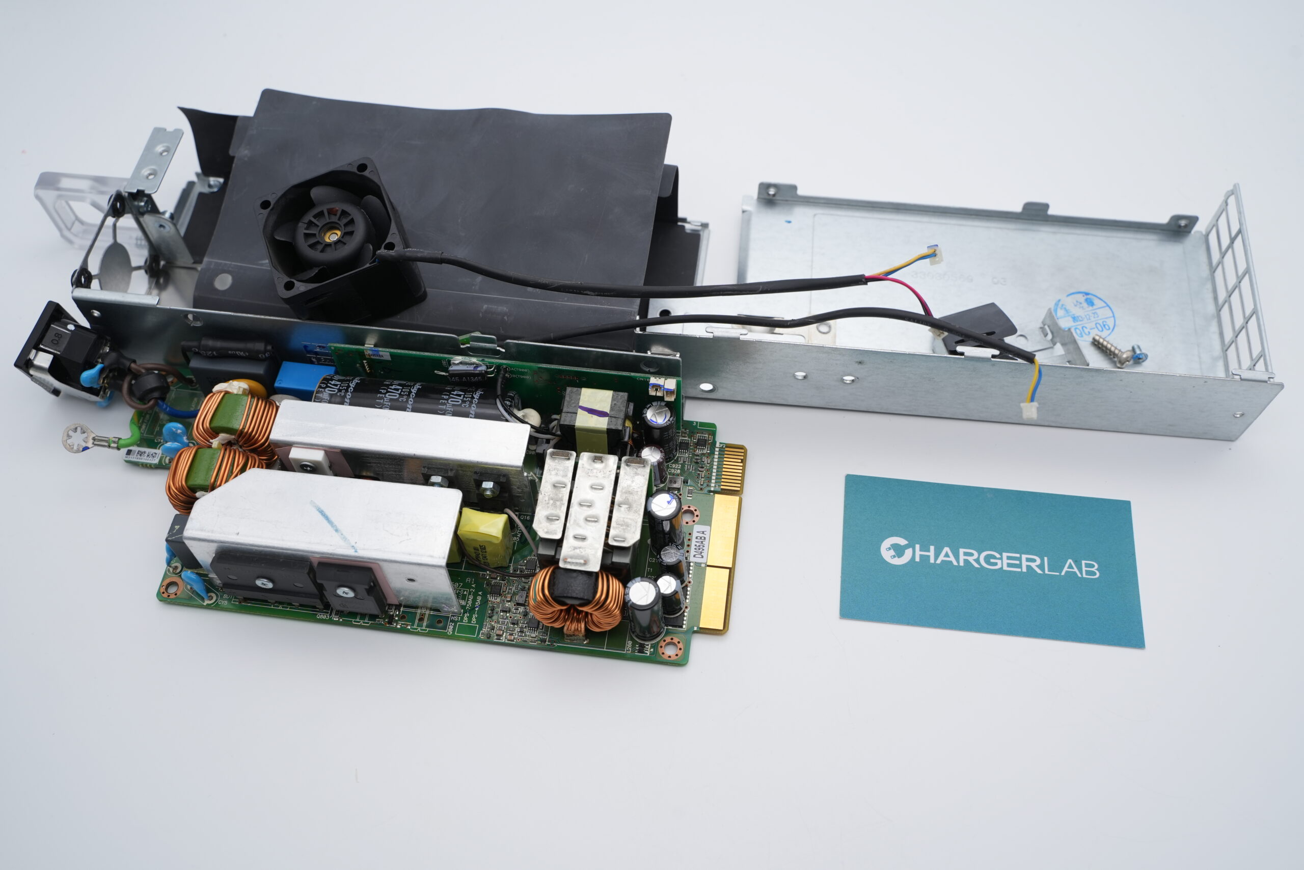
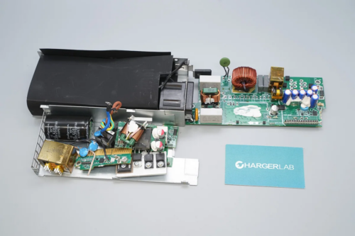
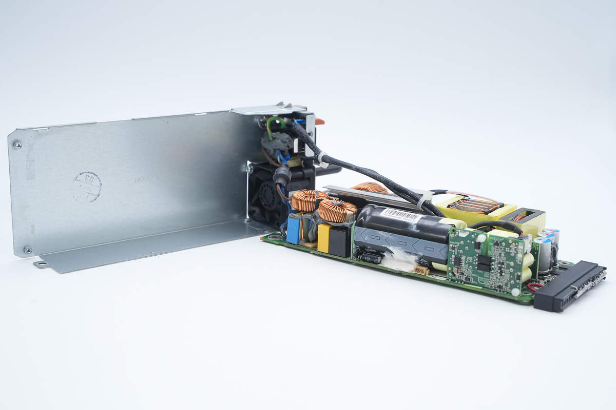
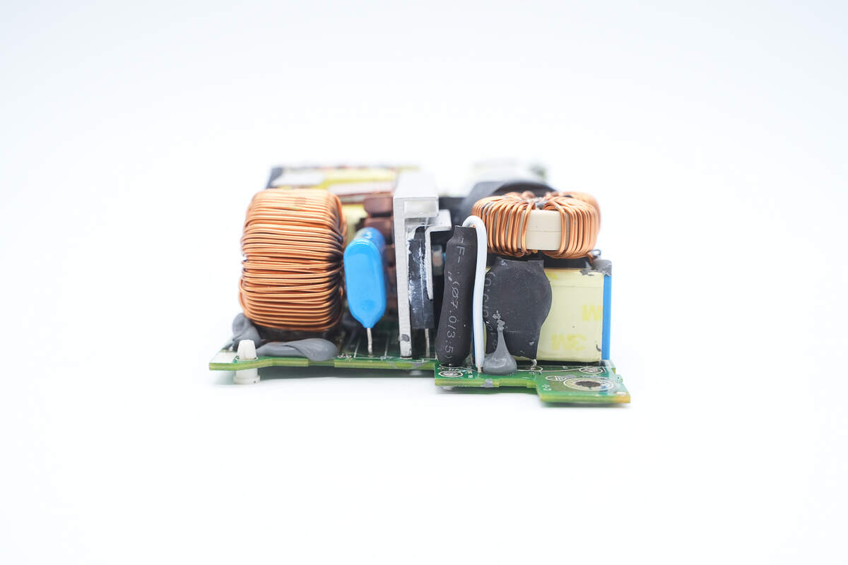
Front view of the PCBA module: the input side is located at the upper right corner, featuring safety X2 capacitors, common mode chokes, and a relay. Below them, the heat sink cools the bridge rectifier, PFC MOSFET, and PFC rectifier. Further down are the film capacitor and the PFC boost inductor.
In the middle area, there is a high-voltage filter capacitor. On the left side is the auxiliary power PCB. Below are filter solid capacitors, a filter inductor, a transformer, and an isolation transformer.
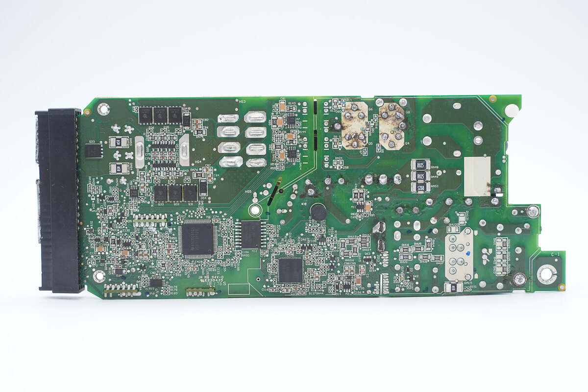
On the back of the module are the PFC controller, phase-shift full-bridge controller, digital isolation chip, and synchronous rectifiers.
The back of the module contains the PFC controller, phase-shift full-bridge controller, digital isolation chip, and synchronous rectifiers.
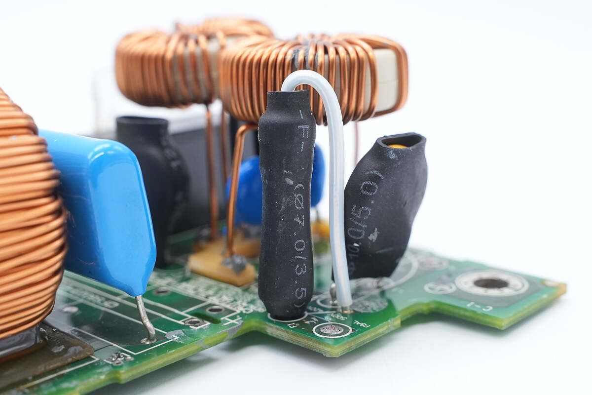
Both the fuse and varistor are insulated with heat-shrink tubing.
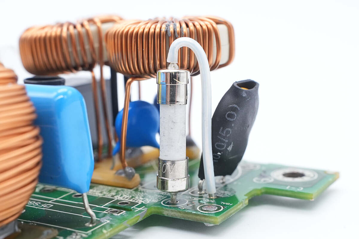
The fuse is rated at 8A.
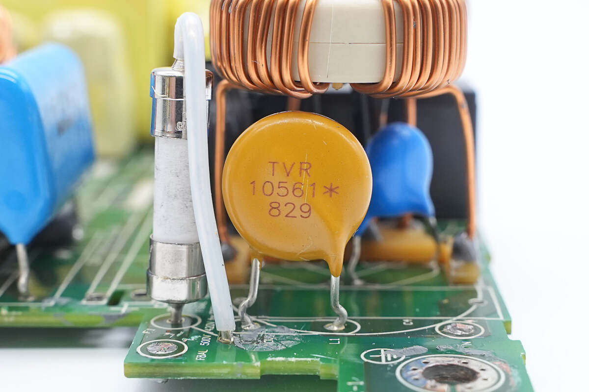
The varistor is model TVR10561 and is used to absorb overvoltage surges.
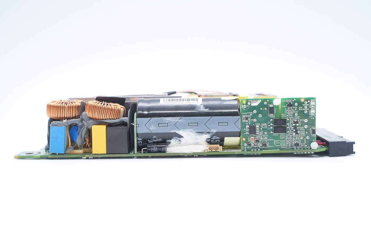
This side features safety X2 capacitors, common mode chokes, a relay, a high-voltage filter capacitor, and the auxiliary power PCB.
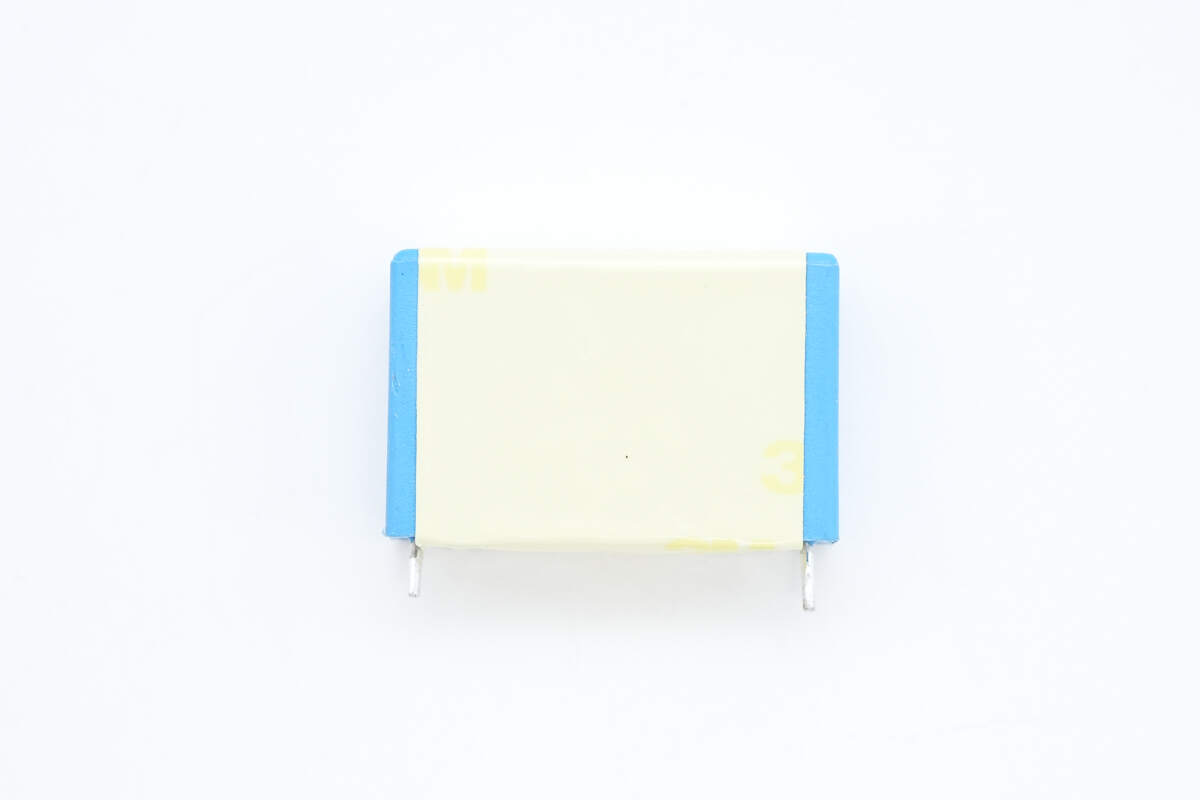
The safety X2 capacitor is insulated with adhesive tape.
It is from Sungho, with a specification of 1 μF.
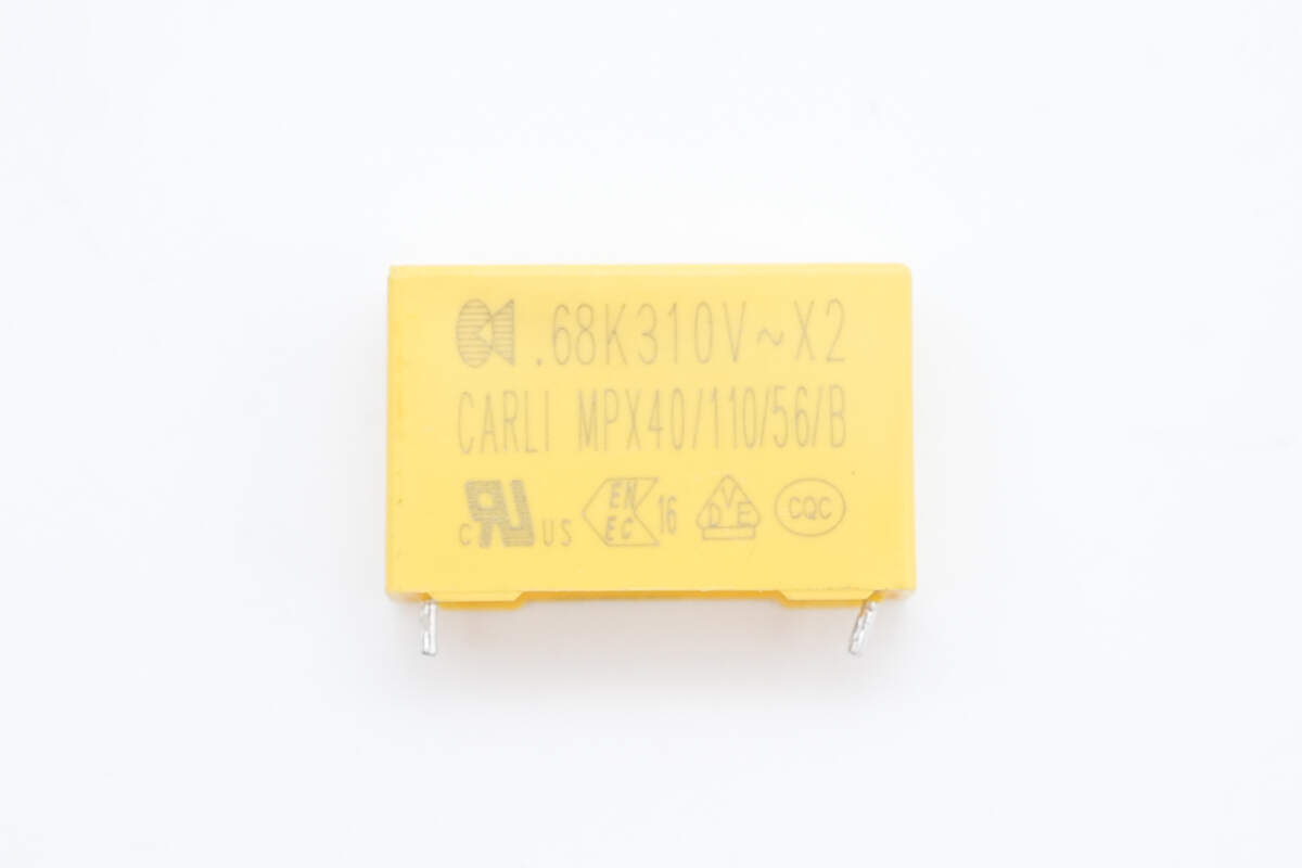
The other safety X2 capacitor is from Carli, with a specification of 0.68 μF.
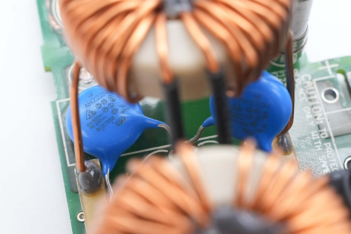
Close-up of two blue Y capacitors.
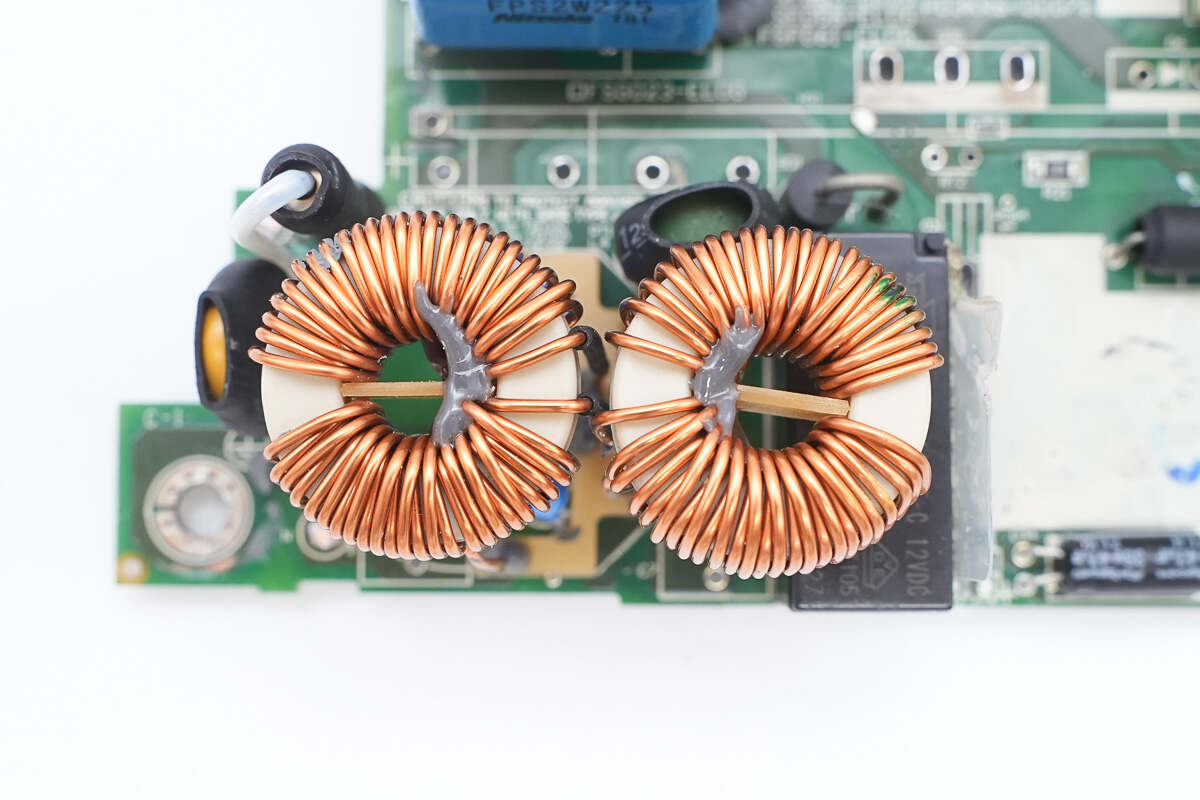
The common mode chokes use toroidal cores and are internally insulated with bakelites.
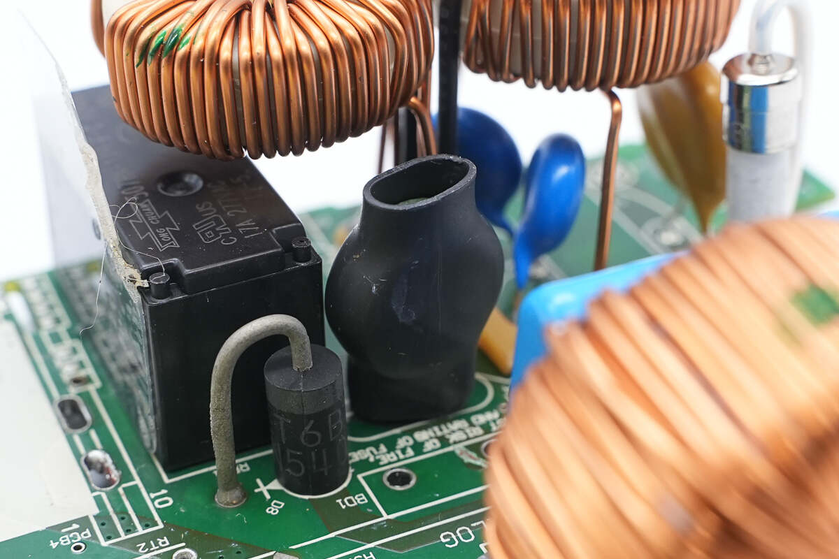
The thermistor is insulated with heat shrink tubing.

The thermistor is from Thinking and is marked with PI 500.
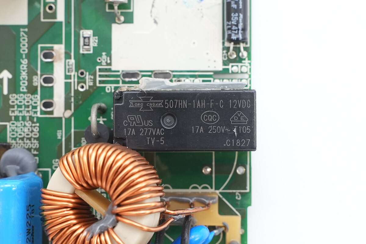
The relay is from SongChuan, model 507HN-1AH-F-C, featuring one built-in normally open contact with a contact rating of 16A at 240VAC, and a coil voltage of 12V.

One side of the heat sink houses the PFC MOSFET and the PFC rectifier.
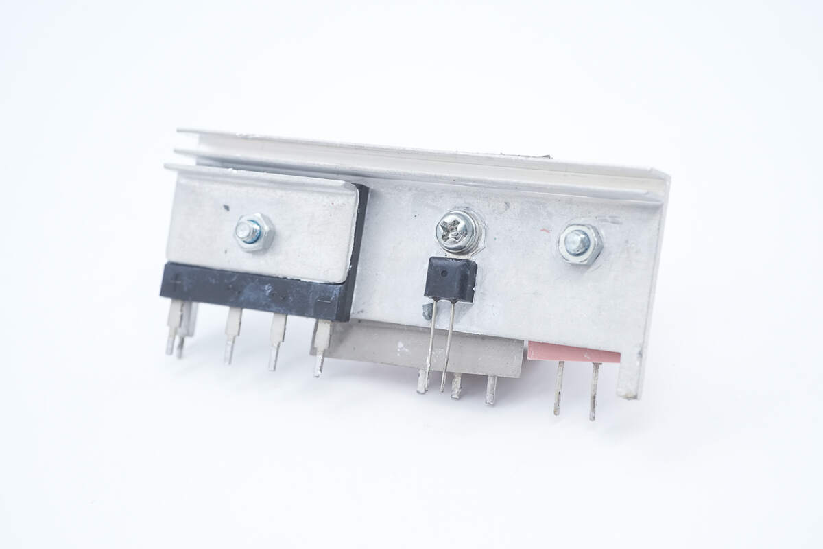
The other side contains the bridge rectifier and the thermistor.
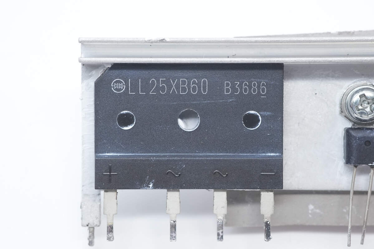
The bridge rectifier is from Shindengen, model LL25XB60, rated at 25A 600V, and uses a 5S package.
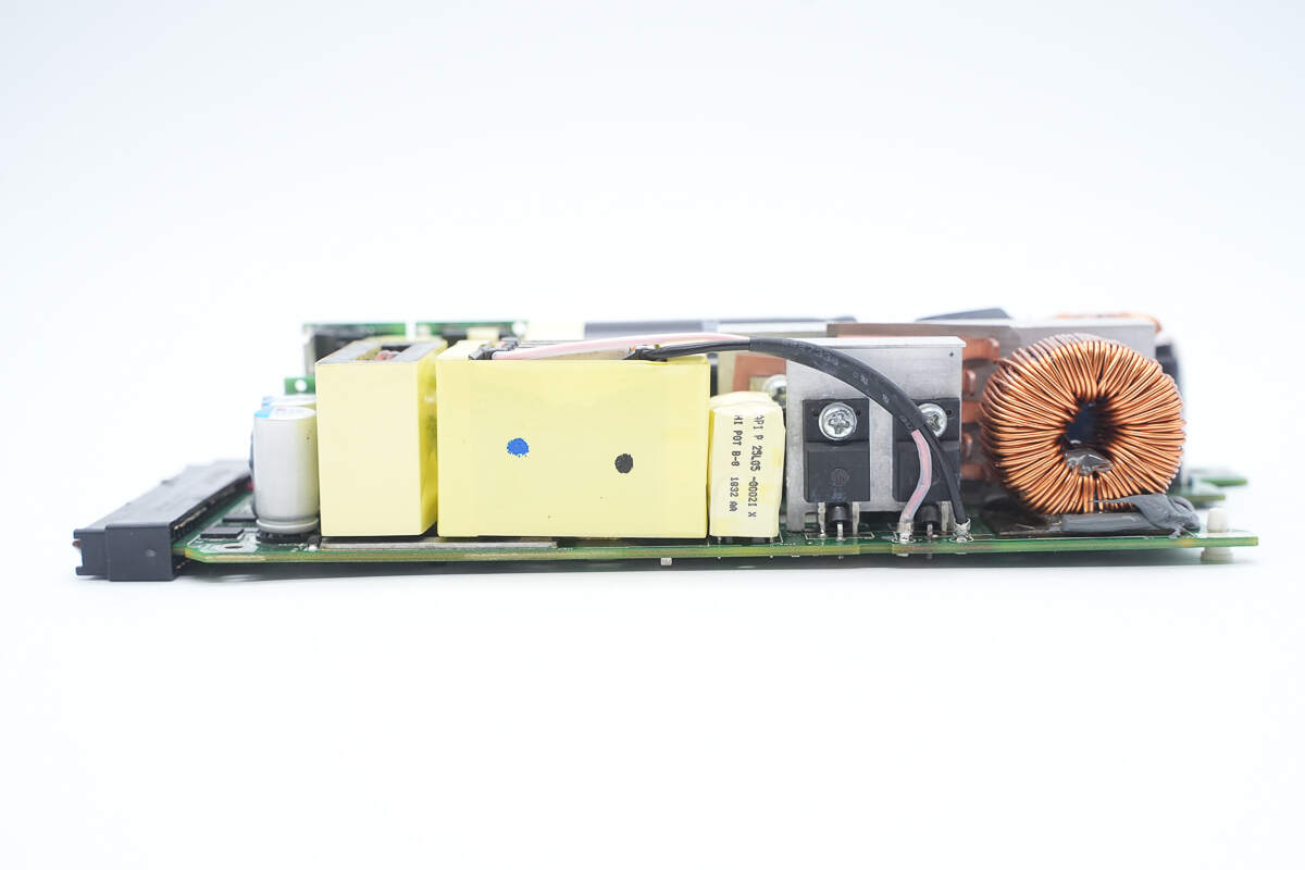
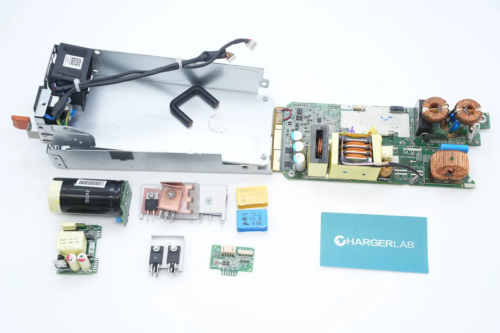
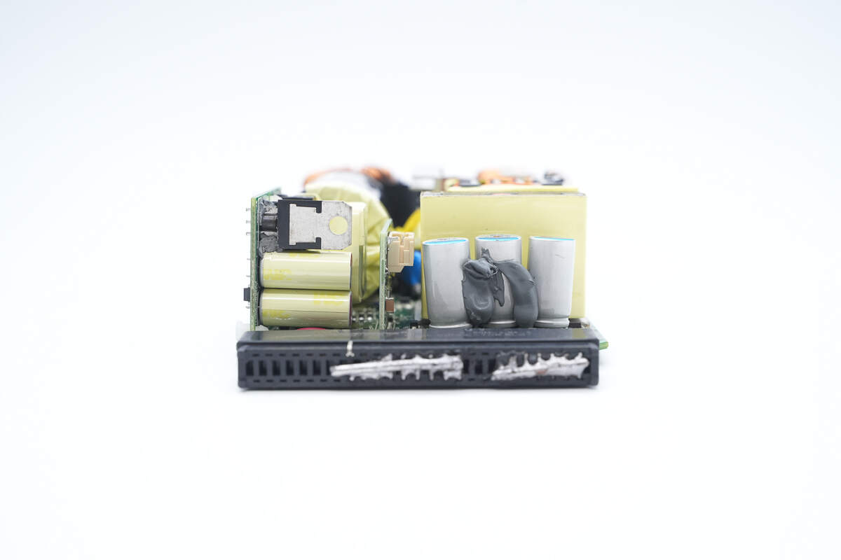
This side is equipped with filter capacitors, a filter inductor, a transformer, an isolation transformer, phase-shift full-bridge MOSFETs, and a PFC boost inductor.

The film capacitor is from Nitsuko, rated at 450V and 2.2 μF.

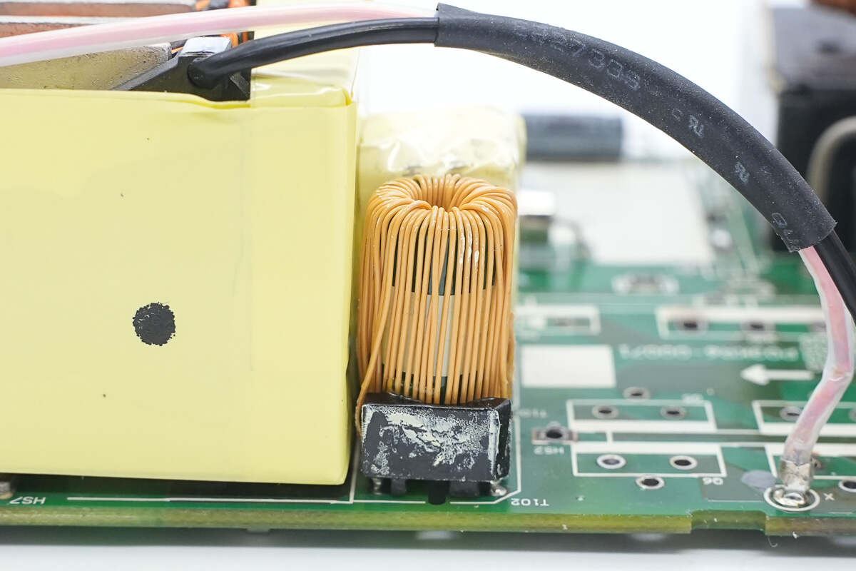
The PFC boost inductor is wound with the magnet and insulated wires.

The PFC controller UCD3138064 from TI. It is a digital power controller with 64kB of embedded flash memory. It supports SPI and I2C interfaces and is suitable for applications including phase-shifted full bridge, single-phase and interleaved PFC, bridgeless PFC, hard-switched full bridge and half bridge, as well as half-bridge and full-bridge LLC. It is available in a VQFN64 package.
The driver used to drive the PFC MOSFET is the UCC27511 from TI, a single-channel high-speed driver featuring a 4A peak sourcing current and 8A peak sinking current. It is available in a SOT-23 package.
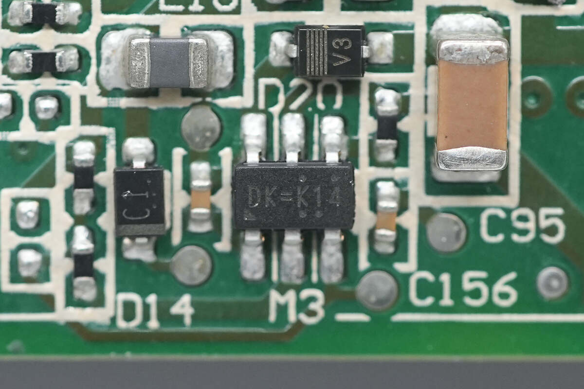
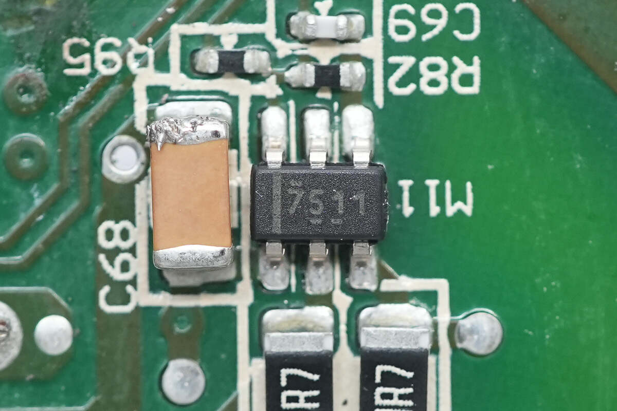
The buck converter is the RT8259 from RICHTEK, a switching regulator that supports an input voltage range of 4.5–24V and provides up to 1.2A output current. It is available in a SOT-23 package.
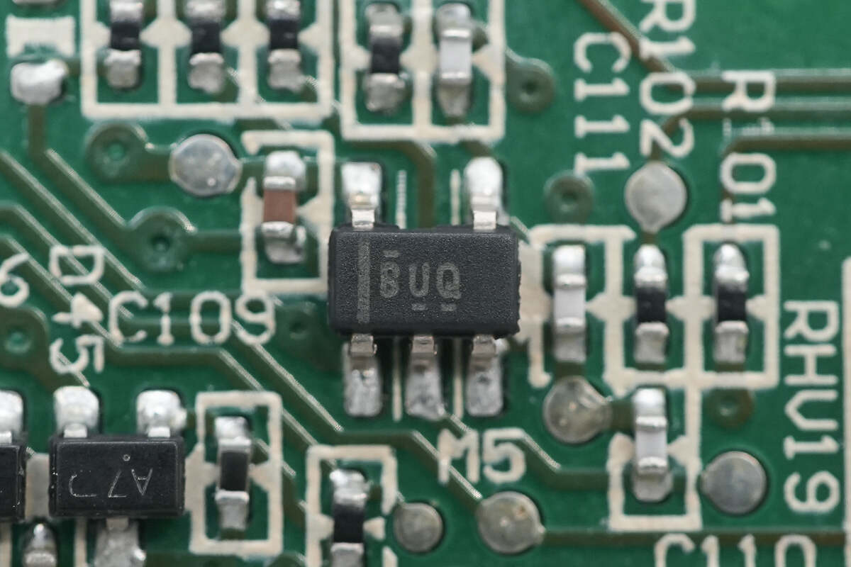
The Op-Amp, marked with BUQ, is the OPA376 from TI. It is a precision, low quiescent current op-amp with rail-to-rail input and output capability. It comes in a SOT-23 package.
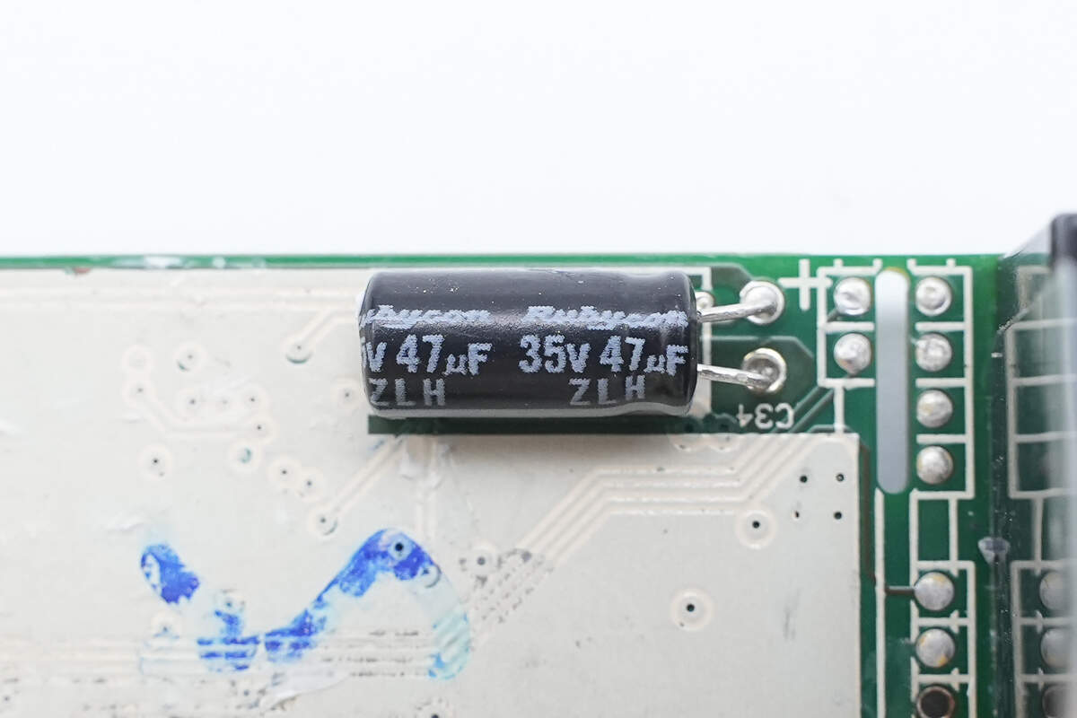
The filter capacitor is from Rubycon, with a specification of 35V 47μF.
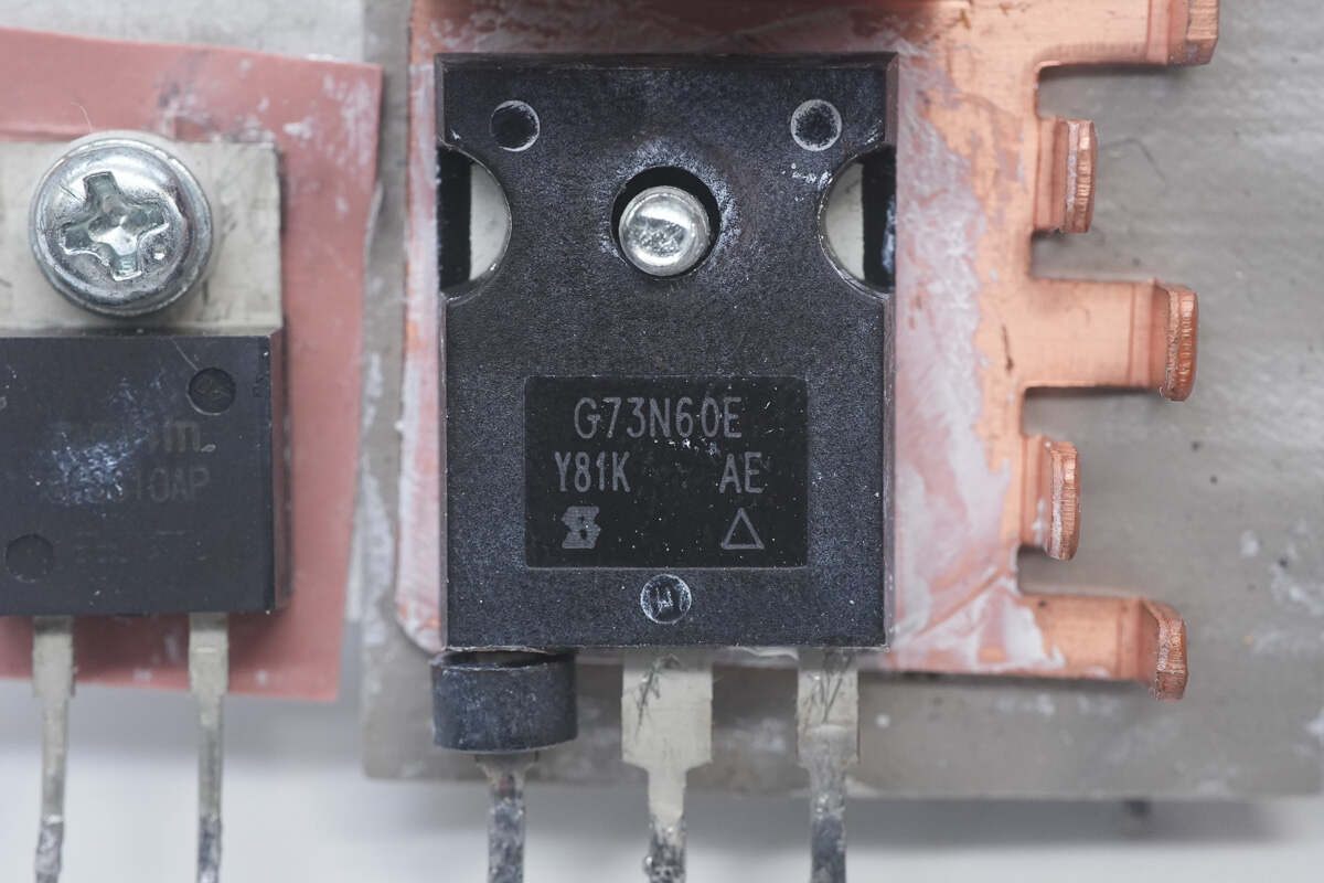
The PFC MOSFET is the SiHG73N60E from VISHAY, an N-channel MOSFET with a voltage rating of 650V and an on-resistance of 32mΩ. It is housed in a TO-247AC package.

Three 25mΩ sense resistors are connected in parallel for measuring the current of the PFC MOSFET.
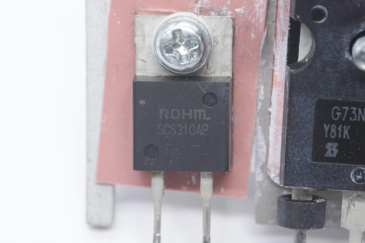
The PFC rectifier is the SCS310AP from ROHM, a SiC diode rated at 650V and 10A. It is packaged in a TO-220ACP case.
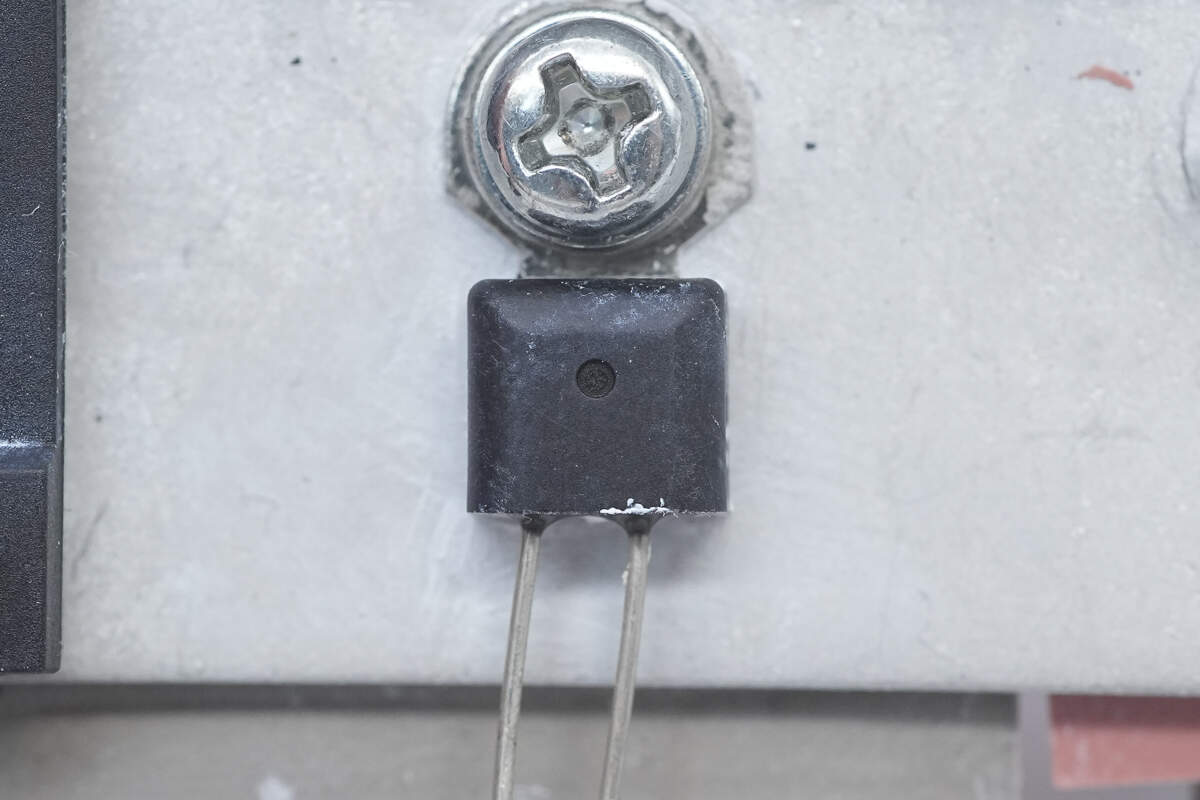
The thermistor is fixed to the heat sink with a screw.
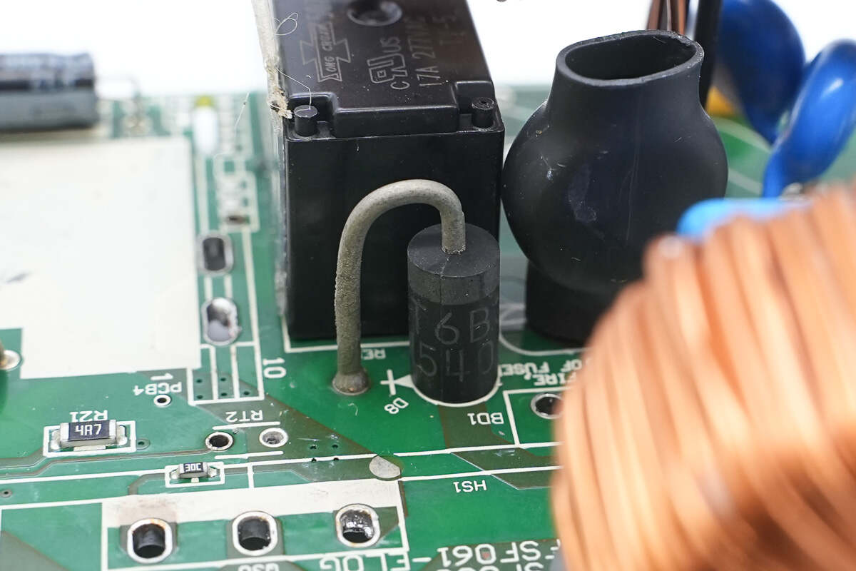
Close-up of the PFC bypass diode.
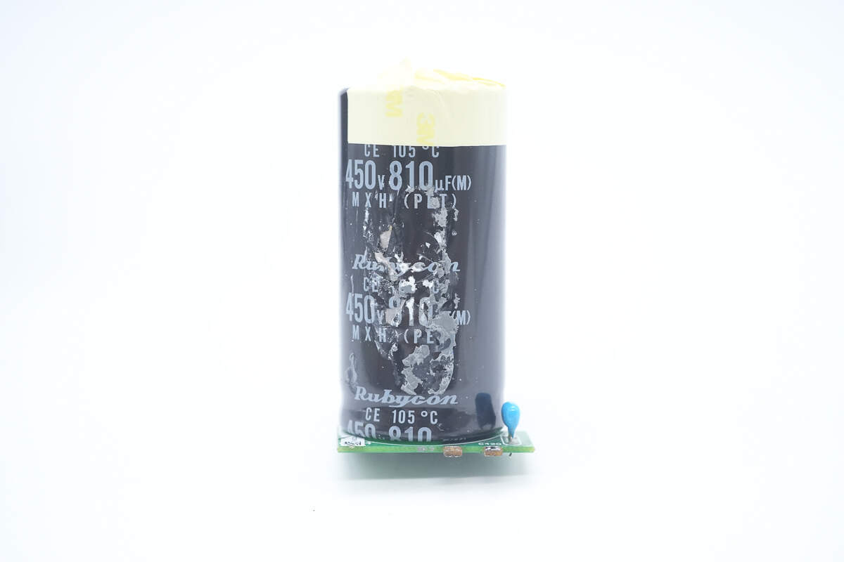
The high-voltage filter capacitor is from Rubycon, an MXH series electrolytic capacitor with a rating of 450V 810μF.
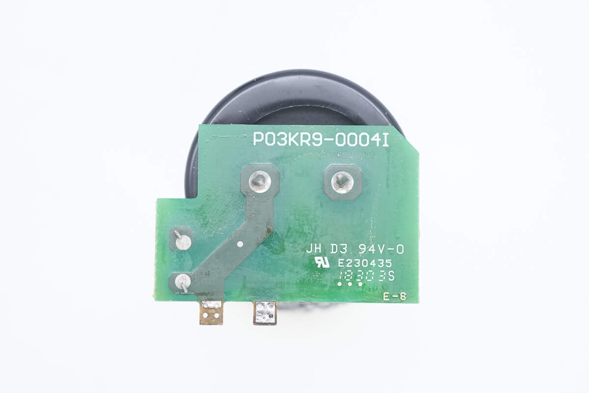
The capacitor is soldered onto a small PCB.
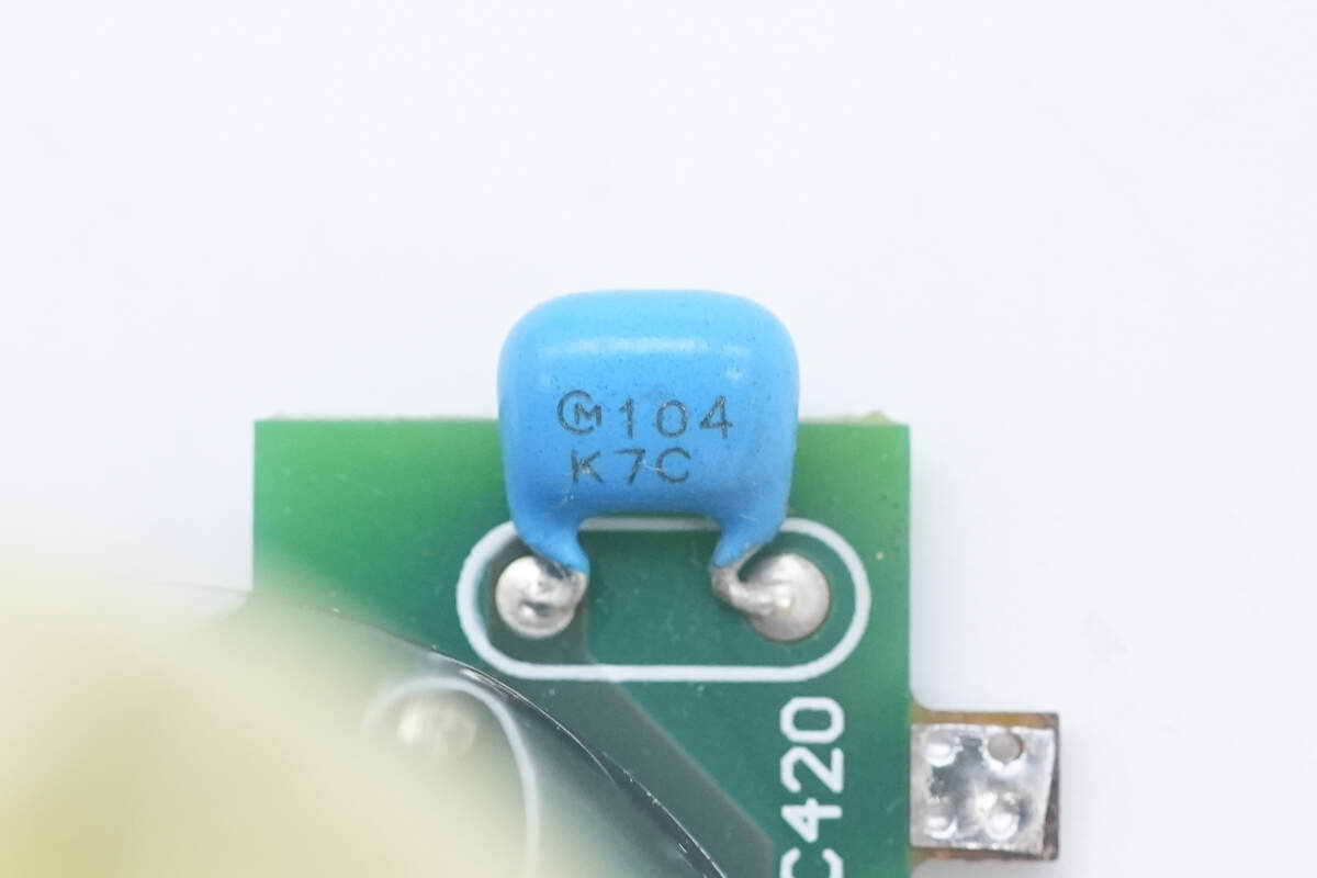
There is a 0.1μF ceramic capacitor on the small PCB.

The phase-shift full-bridge controller from TI, model UCD3138128, is a digital power controller with integrated 128kB flash memory. It features SPI and I2C interfaces and supports phase-shifted full bridge, single-phase and interleaved PFC, bridgeless PFC, hard-switched full bridge and half bridge, as well as half-bridge and full-bridge LLC applications. It is housed in a TQFP80 package.
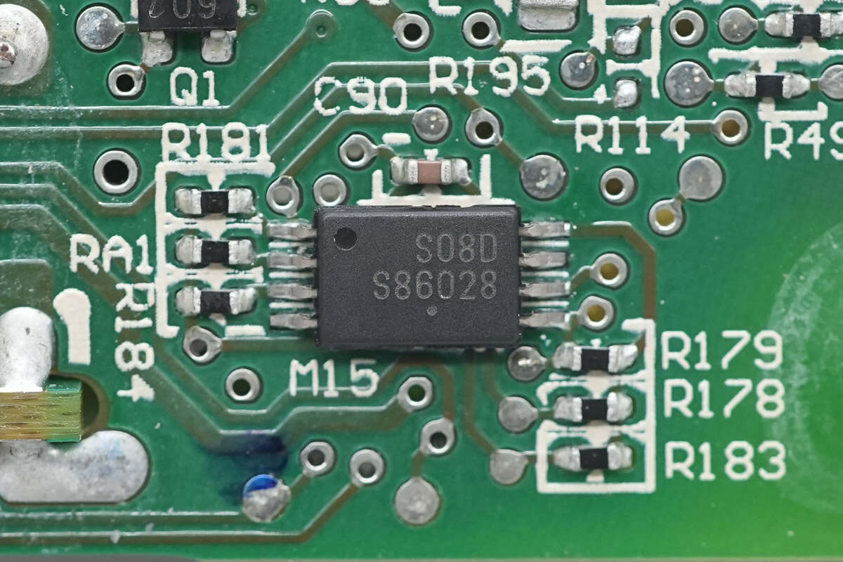
The memory is from Onsemi, marked with S08D, and comes in a TSSOP-8 package.
The buck converter used is the RT8259 from RICHTEK.

The digital isolation chip is the Si8641ED from Skyworks. It features four isolation channels, supports a data rate of 150 Mbps, provides 5.0 kVrms isolation voltage, and is packaged in a WBSOIC16 case.
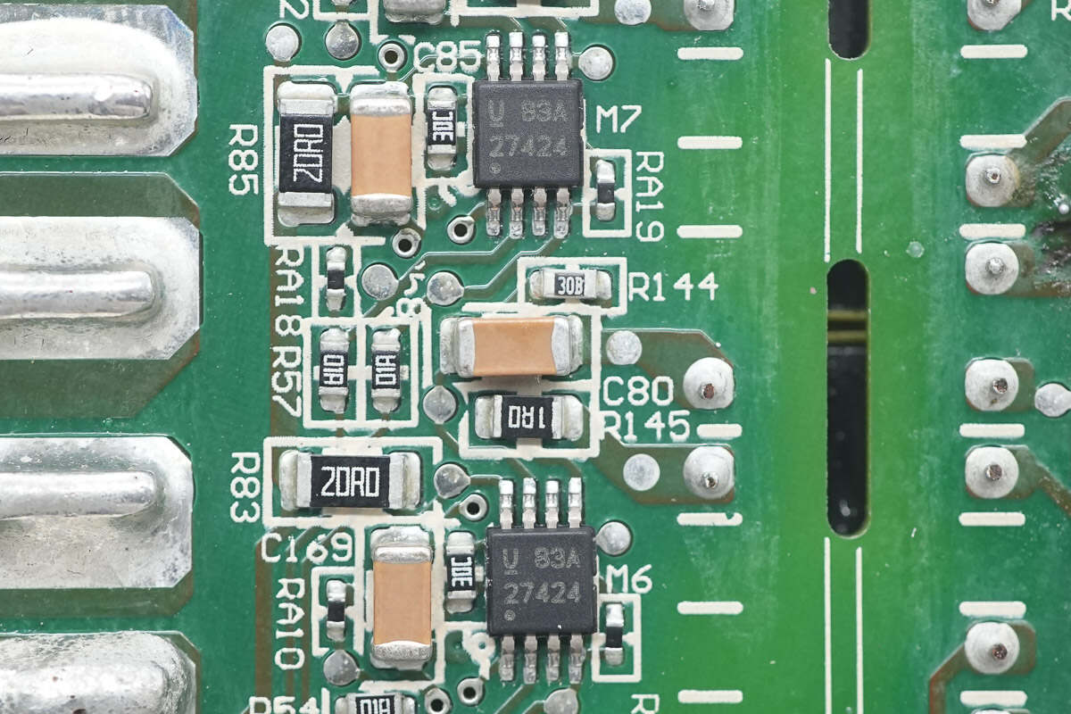
The driver for the isolation transformer is the UCC27424 from TI, a dual-channel gate driver with a 4A output current. It comes in a VSSOP8 package.
The isolation transformer driving the MOSFET is insulated with tape wrapping.
The isolation transformer is wound with multilayer insulated wire.

The phase-shift full-bridge MOSFETs are mounted on the heat sink.

The phase-shift full-bridge MOSFETs are from Infineon, marked with 6R190P6, model IPA60R190C6. They are N-channel MOSFETs with a voltage rating of 650V and an on-resistance of 190mΩ, housed in a TO-220 FP package.
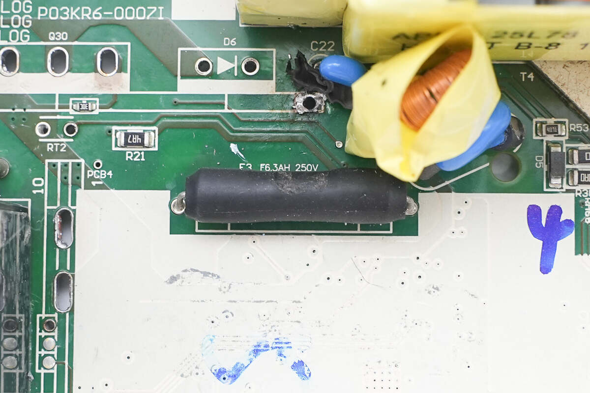
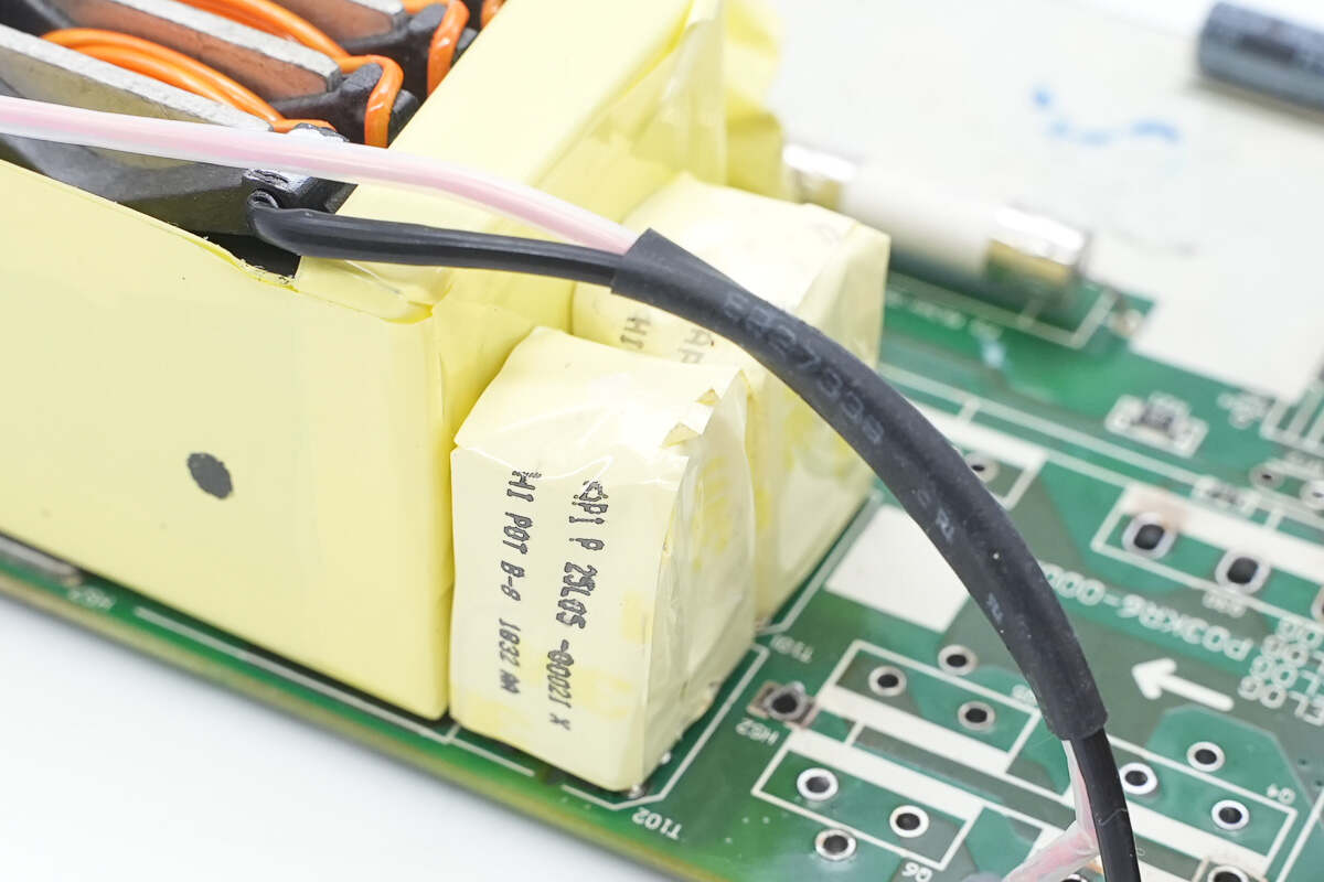
The fuse is rated at 6.3A 250V.

The current transformer is insulated with tape wrapping.
The transformer core is insulated with tape wrapping.
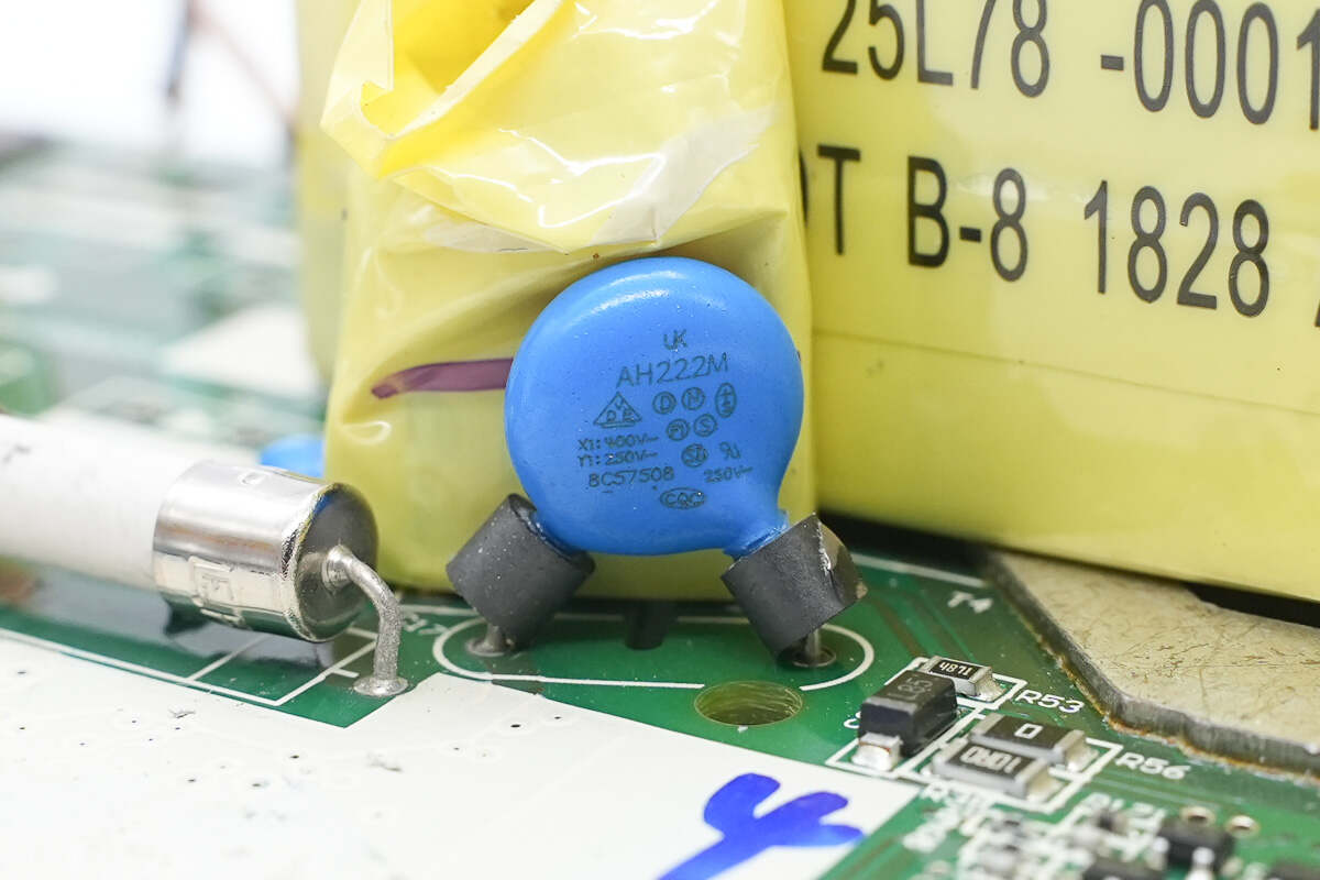
The blue Y capacitor is from Walsin.
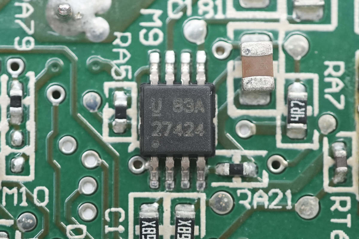
The driver used is the TI UCC27424.

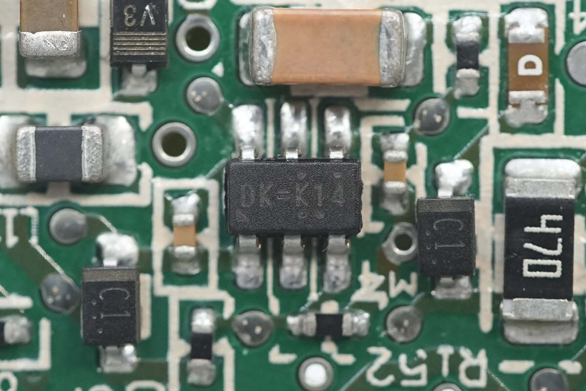
The dual transistor driving the synchronous rectifiers is the QSZ2 from ROHM, marked with Z02. It integrates PNP and NPN transistors and comes in a SOT-25T package.

The synchronous rectifiers are from Infineon, model BSC016N06NS. They are N-channel MOSFETs with a voltage rating of 60V and an on-resistance of 1.6mΩ, packaged in a TDSON-8 case.
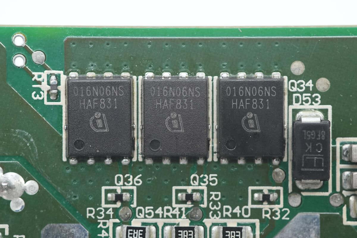
The three synchronous rectifiers are of the same model.
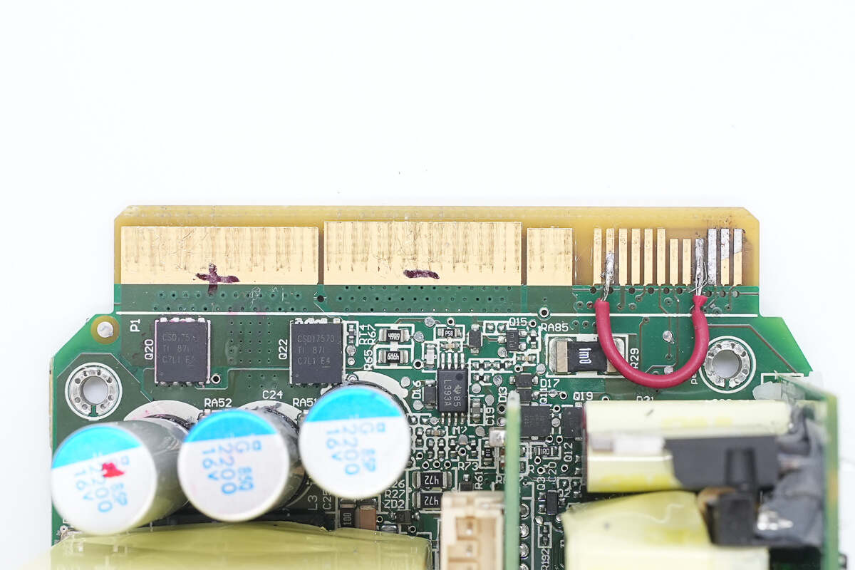
At the output side, there is an auxiliary power PCB, an adapter PCB, an output filter inductor, and filter capacitors.
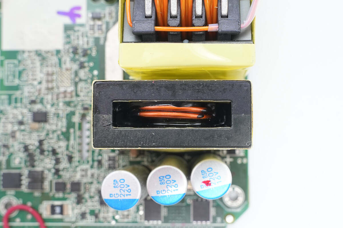
The filter inductor is wound with flat copper wire.
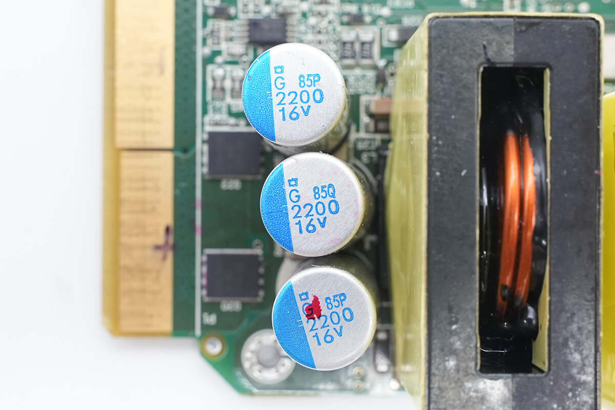
The output filter capacitors are from NCC, part of the PSG series of conductive polymer solid aluminum electrolytic capacitors, with a specification of 2200μF 16V.
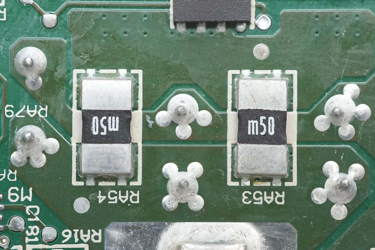
Two 0.5mΩ resistors are used for output current sensing.
The current sensing chip is the INA199B from TI, marked with SHE. It is a 26V-rated, bidirectional zero-drift current shunt amplifier, packaged in an SC70 case.
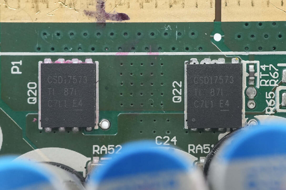
The output control MOSFET is the CSD17573Q5B from TI. It is an N-channel MOSFET with a voltage rating of 30V and an on-resistance of 0.84mΩ, packaged in a SON 5×6 case.

The other output control MOSFET is of the same model.
Close-up of the gold fingers.
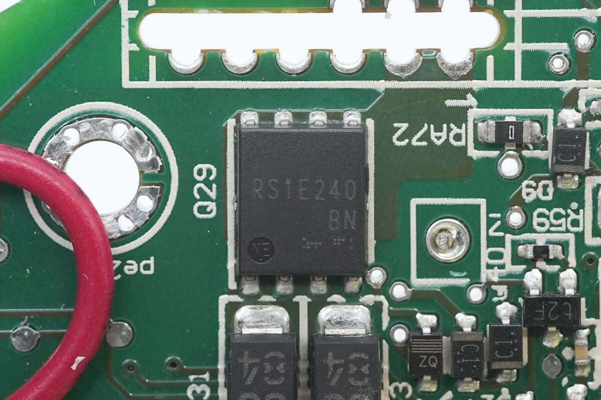
The output control MOSFET is the RS1E240BN from ROHM. It is an N-channel MOSFET with a voltage rating of 30V and an on-resistance of 3.2mΩ, packaged in an HSOP8 case.

The Schottky diodes are from ROHM, marked with 56, model RSX301L-30. They are rated at 30V 3A and come in an SMA package.
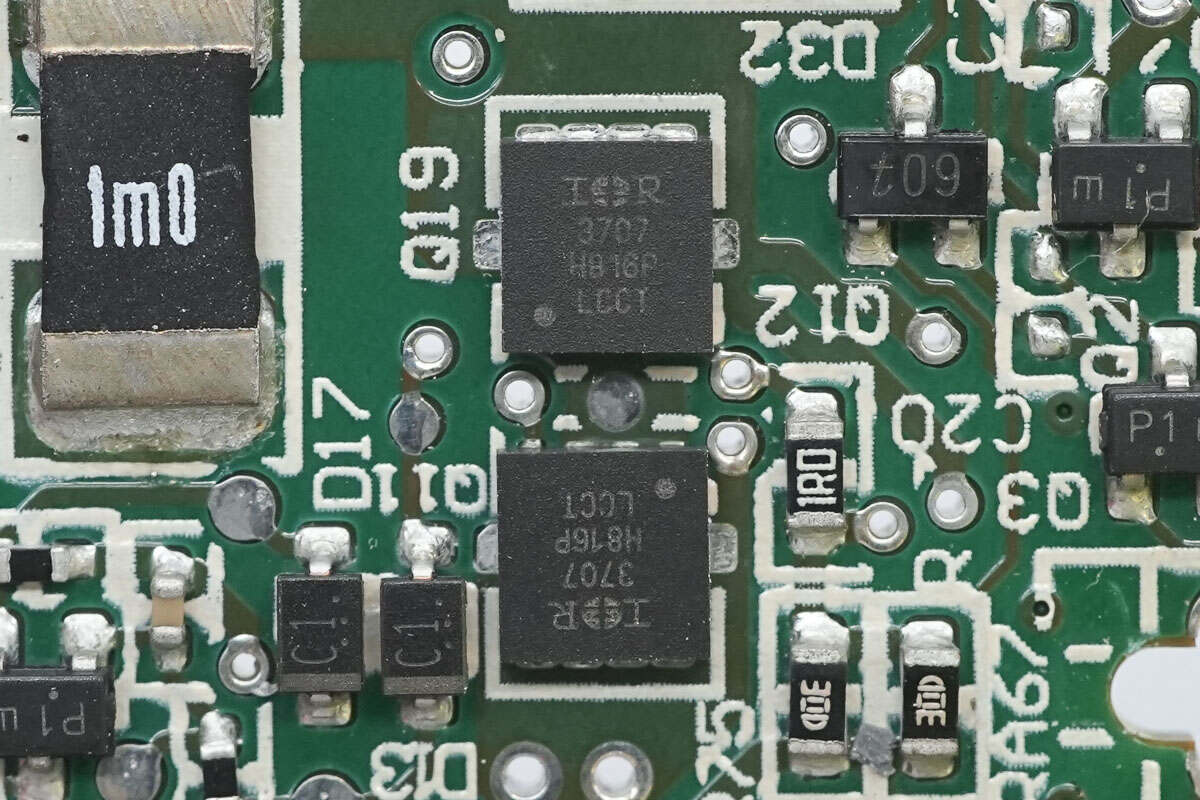
The two output control MOSFETs are from Infineon, model IRFH3707. They are N-channel MOSFETs with a voltage rating of 30V and an on-resistance of 12.4mΩ, packaged in a PQFN 3×3 case.

Close-up of the 1mΩ current sense resistor.
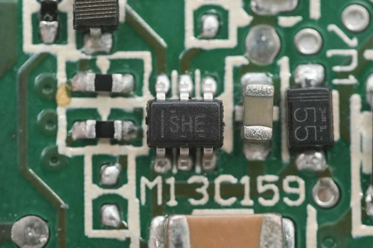
The current sensing chip used is the TI INA199B.

Close-up of the TI LM393A dual voltage comparator.

Close-up of the TI LM358A dual Op-Amp.

On the right side of the auxiliary power PCB are the fuse and MOSFET; the transformer is located in the middle; on the left side is a rectifier and two filter capacitors.
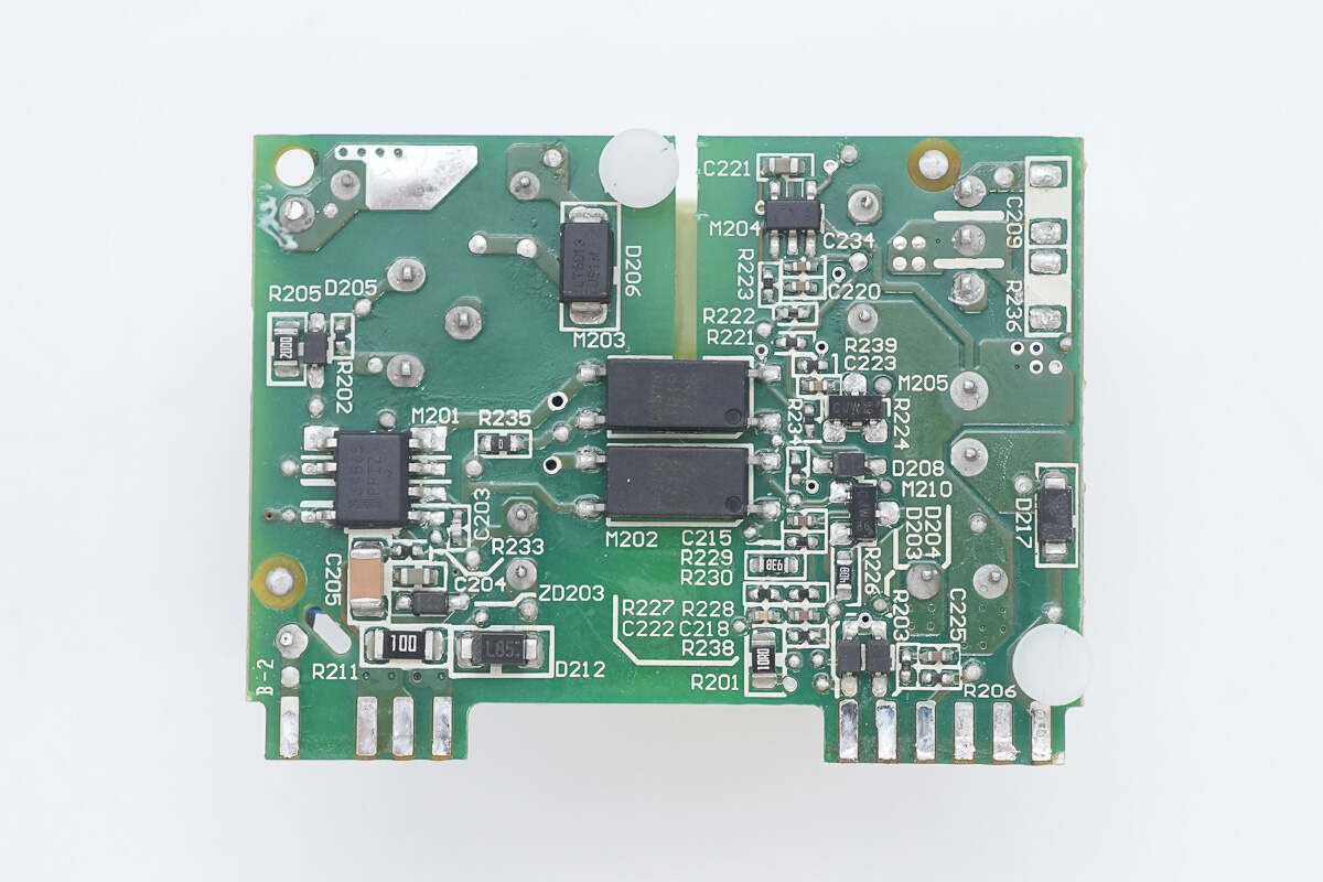
On the back side, there are the switching power supply chip, feedback optocouplers, and a voltage comparator.

The input fuse is insulated with heat shrink tubing and rated at 1.25A.
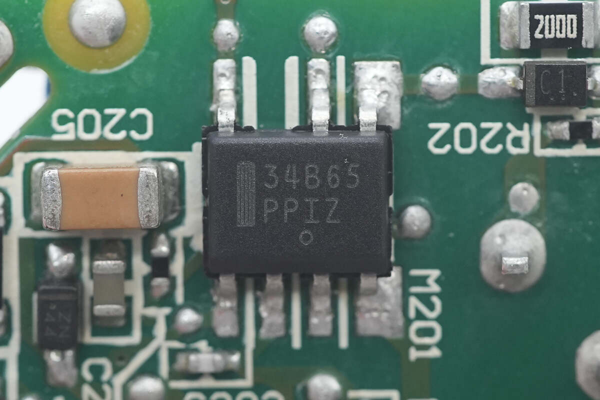
The switching power supply chip is the NCP1234BD65 from Onsemi, marked with 34B65. It is a current-mode flyback controller with a fixed switching frequency of 65kHz, packaged in an SOIC-7 case.
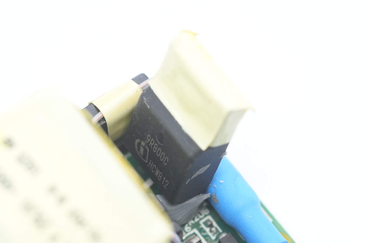
The auxiliary power MOSFET is the IPA90R800C3 from Infineon, marked with 9R800C. It is an N-channel MOSFET with a voltage rating of 900V and an on-resistance of 800mΩ, packaged in a TO-220 FP case.
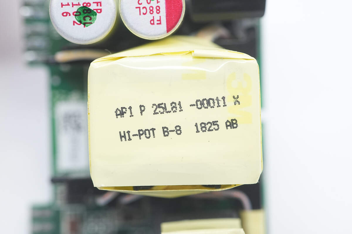
The transformer is tightly insulated with tape wrapping.
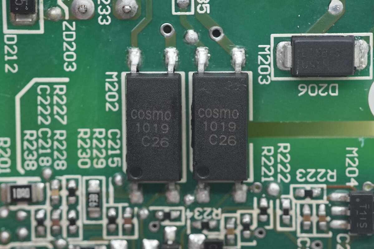
COSMO 1019 optocouplers are used for output voltage feedback.
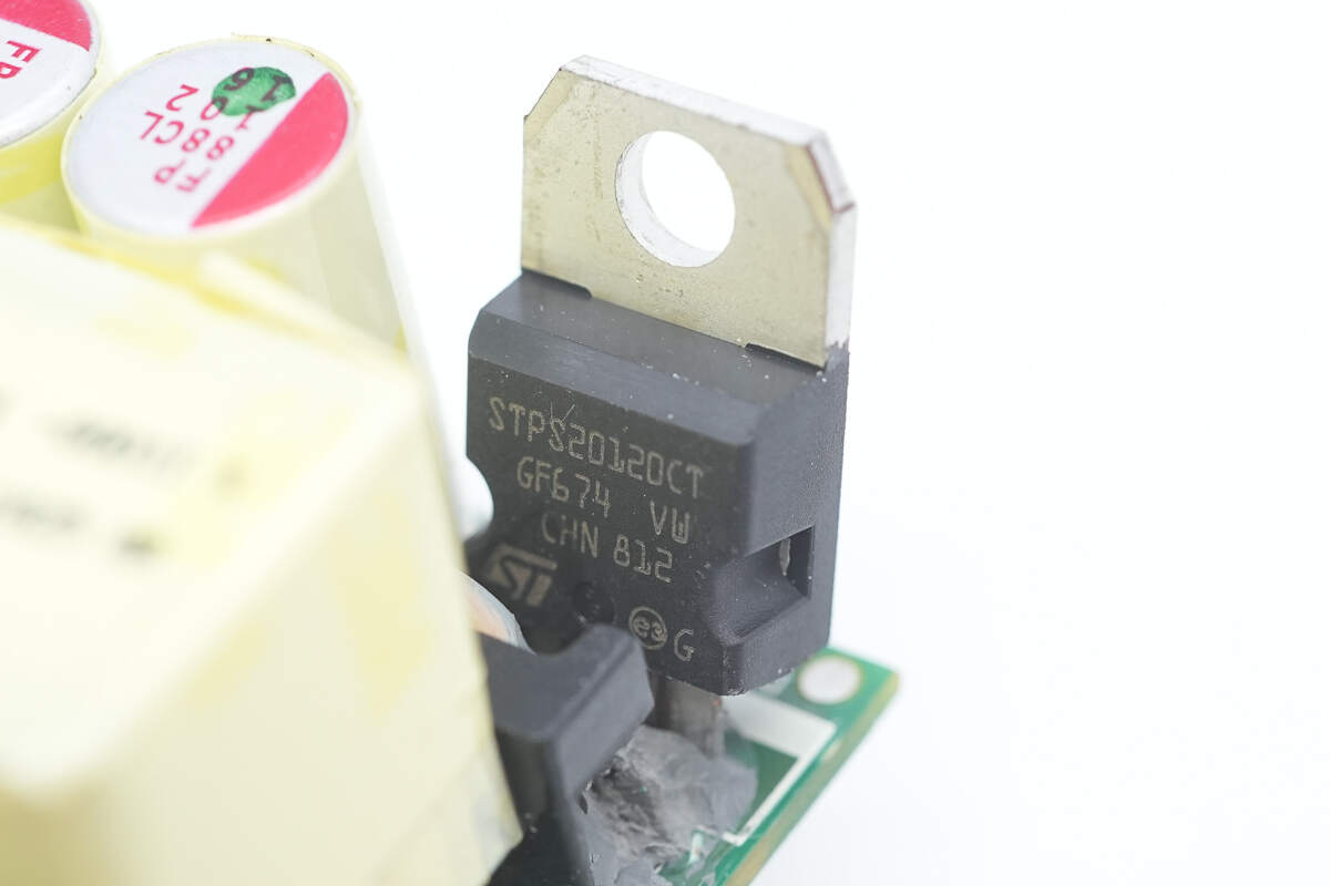
The rectifier is from STMicro, model STPS20120CT, rated at 120V 20A, and packaged in a TO-220AB case.
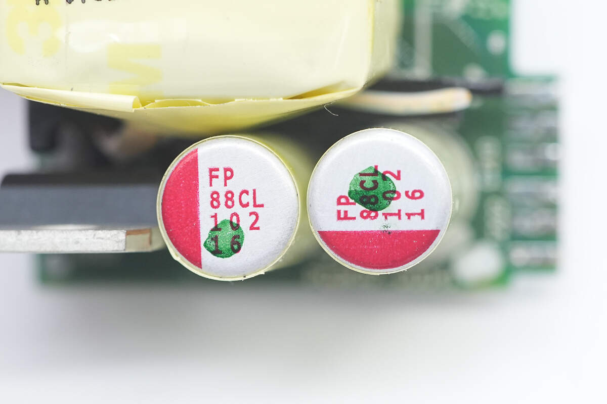
The filter capacitors are from Nichicon, with a specification of 1000μF 16V.

The voltage comparator is the TL331 from TI, marked with T1IS. It is a high-voltage single-channel differential comparator, packaged in an SOT-23 case.
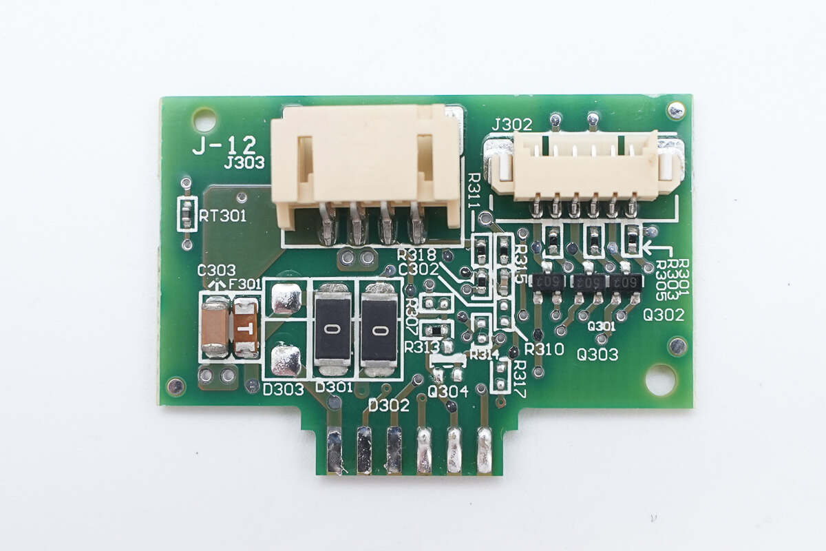
The connecting PCB includes connectors for the fan and indicator lights. The fan power supply is protected by a fuse.
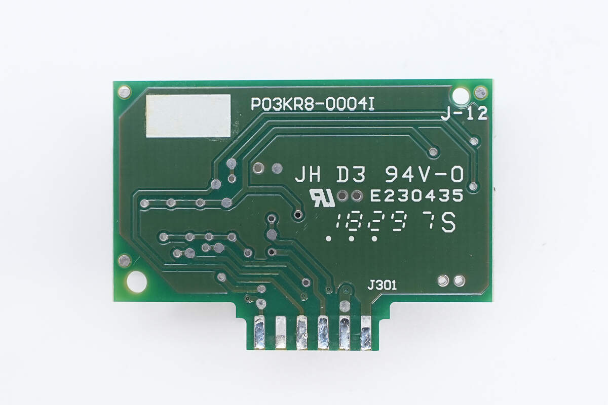
There are no components on the back.

Well, those are all components of the AcBel 1100W Platinum SiC Server Power Supply.
Summary of ChargerLAB
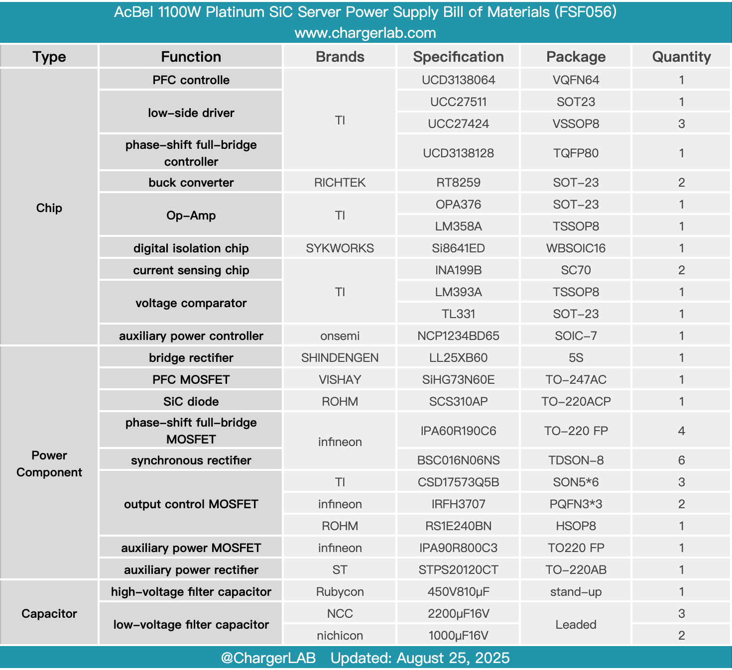
Here is the component list of the AcBel 1100W Platinum SiC Server Power Supply for your convenience.
It supports a wide input voltage range of 100–240V, with a rated output power of 1100W. The main power supply output voltage is 12.2V, and the auxiliary power output voltage is 12V. The input side features a C14 power inlet, a cooling fan, LED indicators, and a carrying handle. The output side is equipped with gold fingers designed for hot-swappable operation.
After taking it apart, we found that it uses a PFC + phase-shift full-bridge architecture. Both the PFC controller and the phase-shift full-bridge controller are from TI. Communication between them is achieved via the Skyworks Si8641ED digital isolation chip. The PFC MOSFET is VISHAY SiHG73N60E, paired with a ROHM SCS310AP silicon carbide diode.
The phase-shift full-bridge MOSFETs use Infineon IPA60R190C6 and are driven through an isolation transformer. The synchronous rectifiers are Infineon BSC016N06NS. The auxiliary power supply controller adopts the Onsemi NCP1234BD65 paired with Infineon IPA90R800C3 MOSFET, using STMicro STPS20120CT Schottky diode for rectification. All capacitors are from Japanese brands, and the components are all internationally recognized first-tier brands. The workmanship and material quality are solid and reliable.
Related Articles:
1. Teardown of EcoFlow RAPID Pro 140W 4‑Port GaN Charger (EF-WC-140-CN)
2. Teardown of MSI 140W USB-C Power Adapter (ADP-140AB B)
3. Teardown of MECHREVO 140W USB-C GaN Power Adapter (AY140AA-1C-CH)