Introduction
Recently, we came across a server power supply from xFusion. This unit supports 220–240V AC or 240V DC input, with an output voltage of 12.1V and an output current of 165.3A, delivering a total output power of 2000W. Under derated input conditions, the output power is automatically adjusted to 1000W or 1600W.
The input side features a cooling fan, power socket, and status indicator LED, while the output side uses a gold finger connector. Internally, the power supply adopts a PFC + LLC architecture and complies with the 80 PLUS Platinum efficiency standard.
Next, let’s take it apart to examine its internal components and structure.
Product Appearance
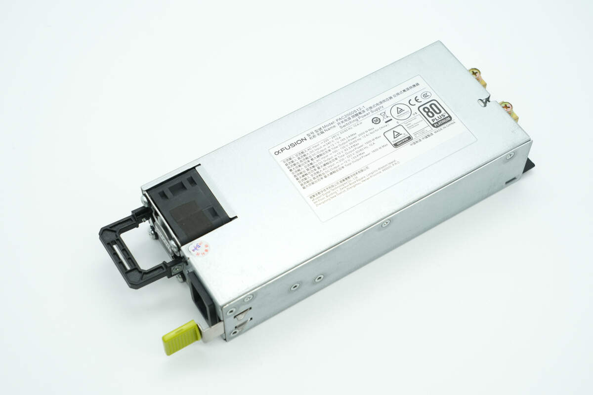
The xFusion 2000W Platinum server power supply features a metal casing assembled with screws.
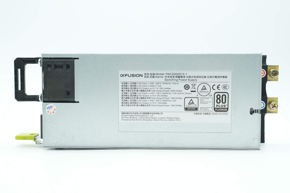
The nameplate is affixed on the front.
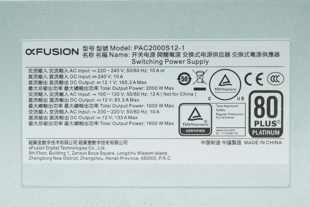
Model: PAC2000S12-1
AC Input: 200-240V; 50/60Hz; 10A
DC Input: 240V; 10A
DC Output: 12.1V; 165.3A Max
Maximum Total Output Power: 2000W Max
AC Input: 100-120V; 50/60Hz; 12A
DC Output: 12.1V; 83.3A Max
Maximum Total Output Power: 1000W Max
AC Input: 200-220V; 50/60Hz; 10A
DC Output: 12.1V; 133.3A Max
Maximum Total Output Power: 1600W Max
xFusion Digital Technology Co., Ltd.
Made in China
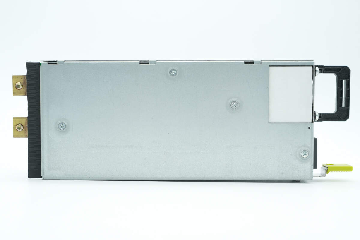
There are screws on the back to secure the internal PCBA module.
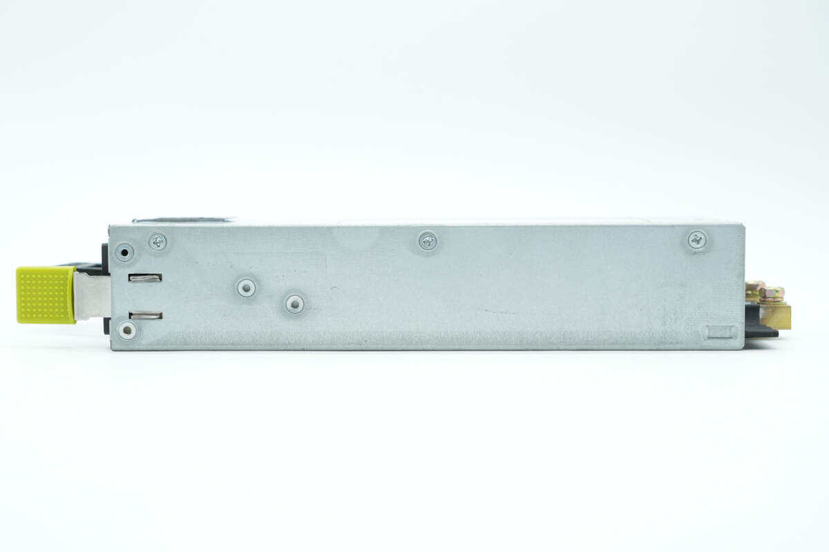
The sides are also secured with screws.
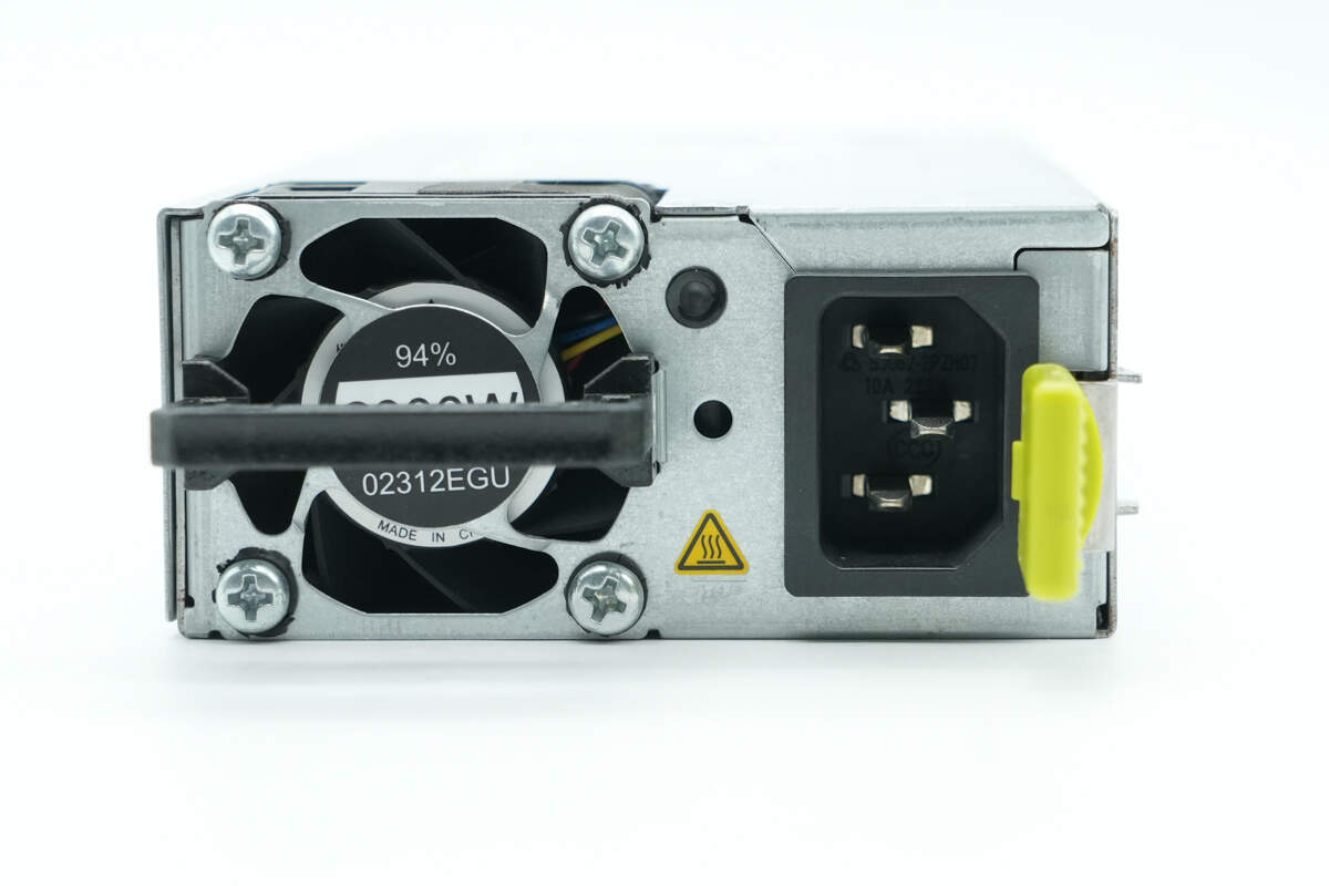
The input side has a handle, cooling fan, power indicator light, three-prong power socket, and a release latch.
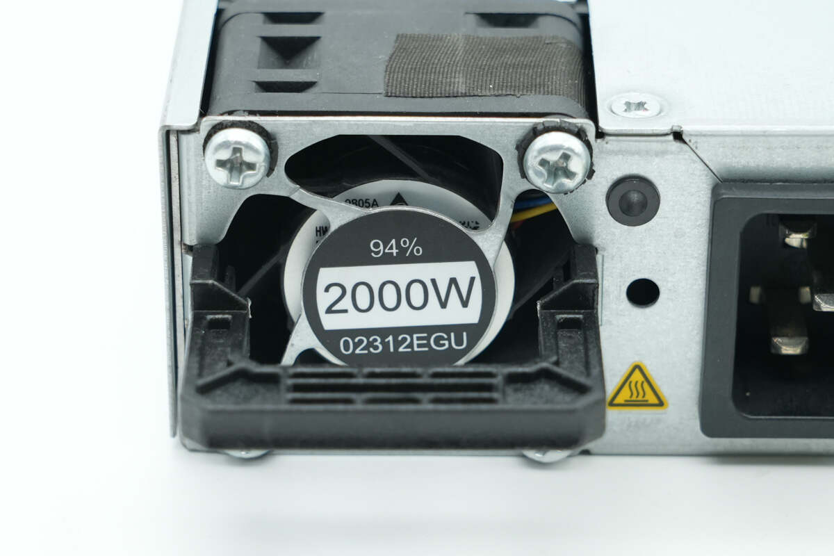
The fan features an integrated guard labeled with conversion efficiency and output power.
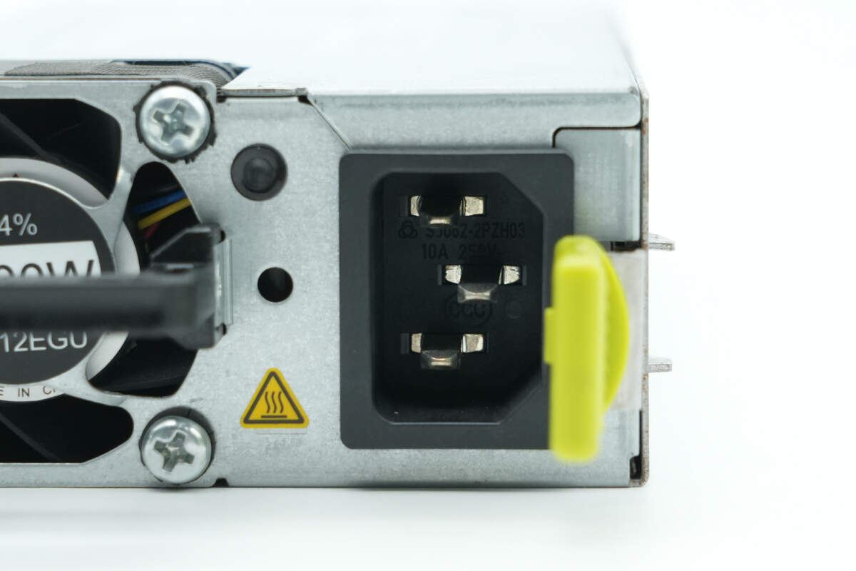
Close-up of the three-prong power socket on the input side.
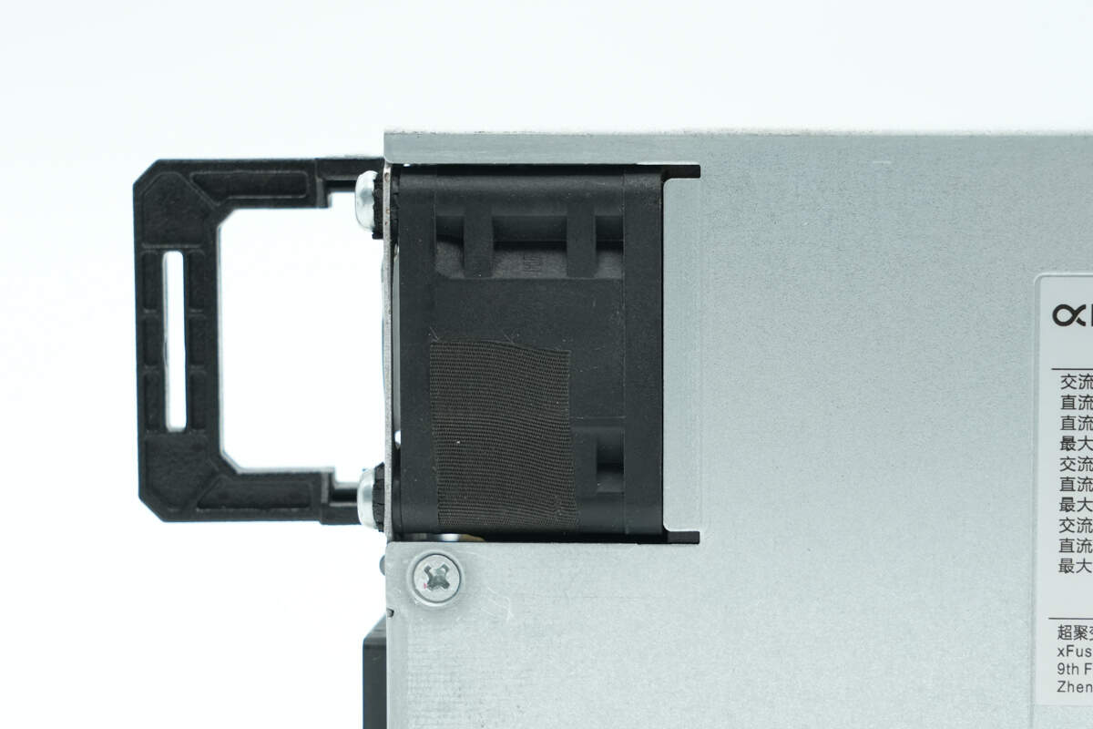
There is a cutout corresponding to the cooling fan position to reduce the thickness.
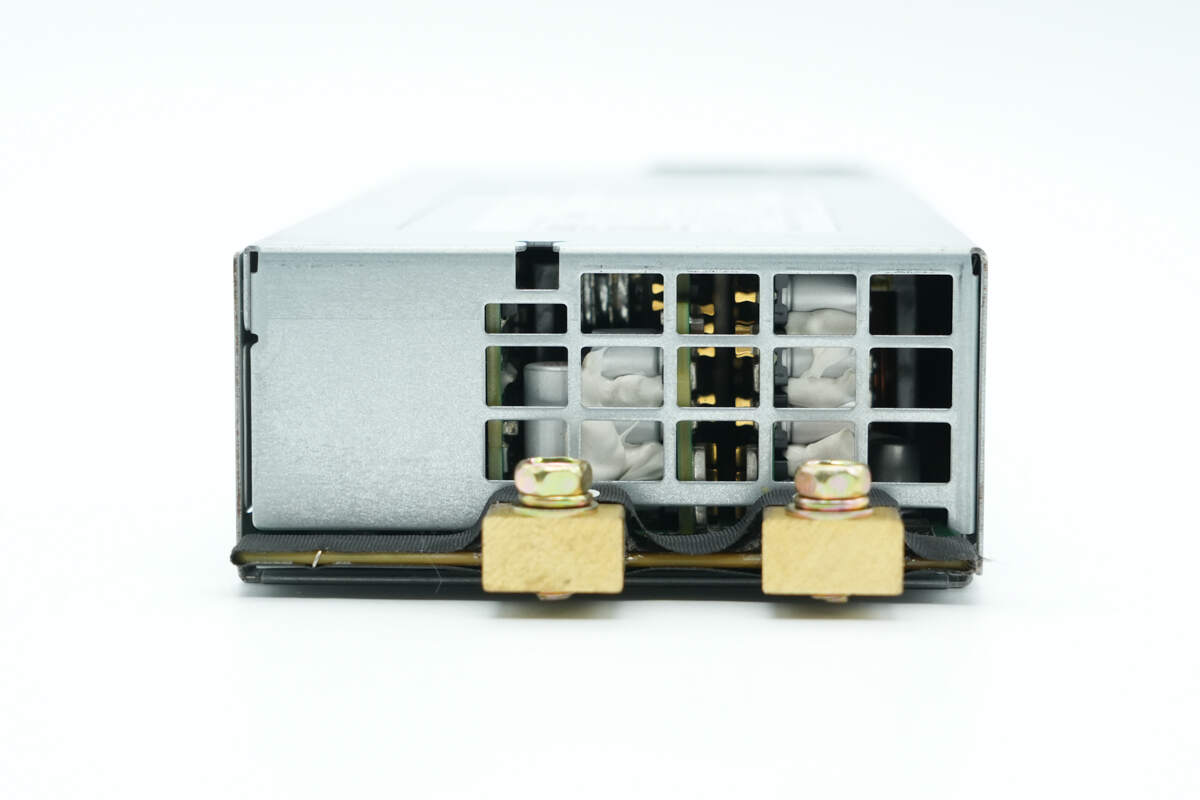
The output side gold fingers are soldered with terminal posts.
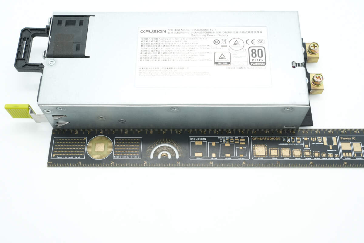
The length of the module is about 205 mm (8.071 inches).
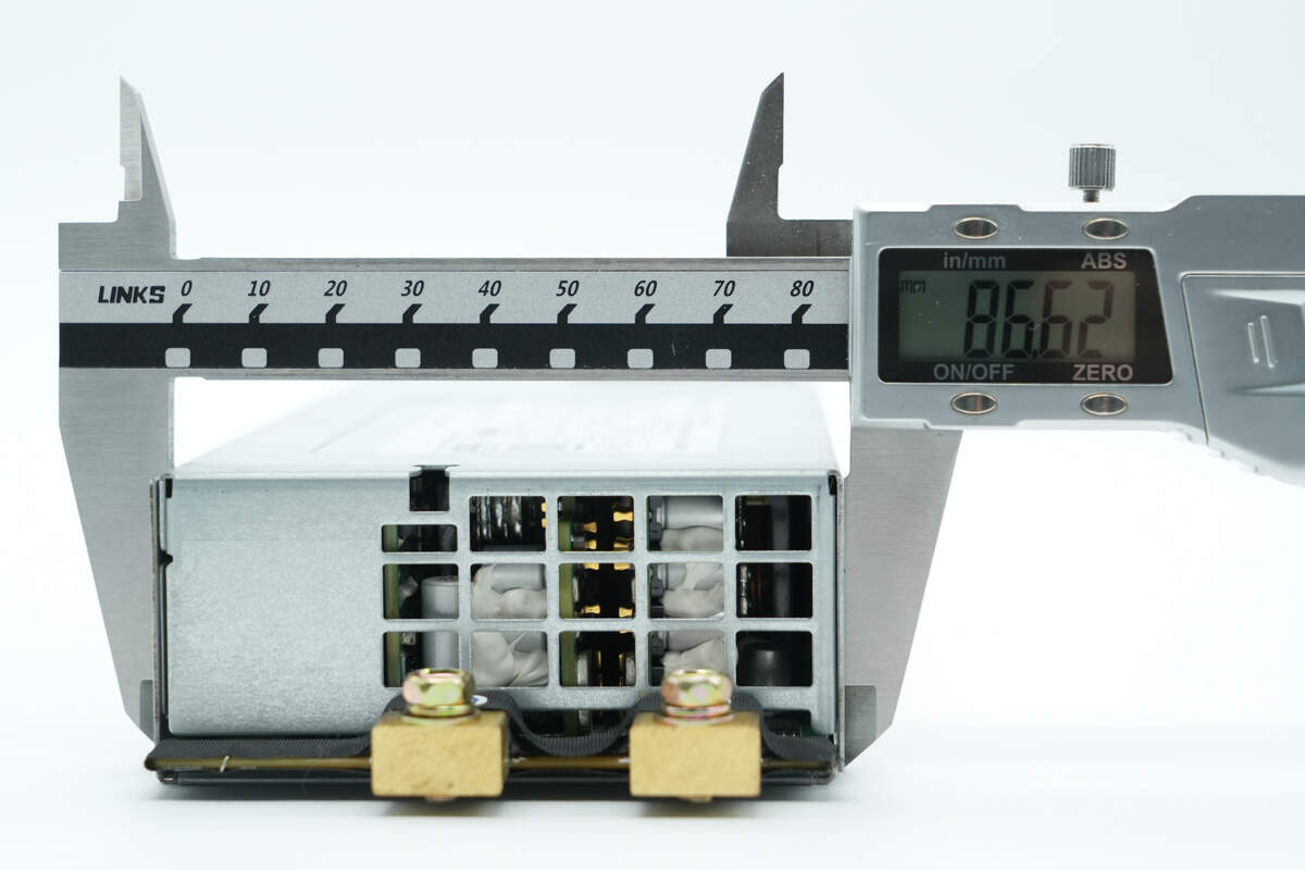
The width is about 86.6 mm (3.41 inches).
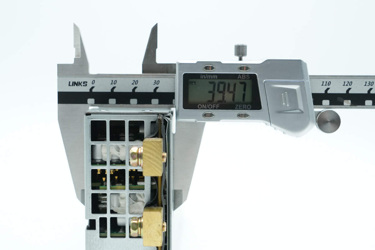
The thickness is about 39.5 mm (1.56 inches).
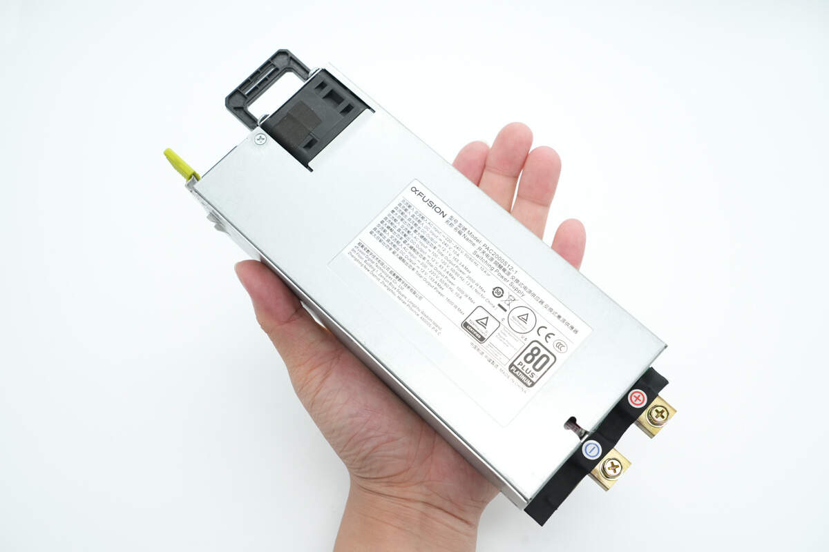
That's how big it is in the hand.
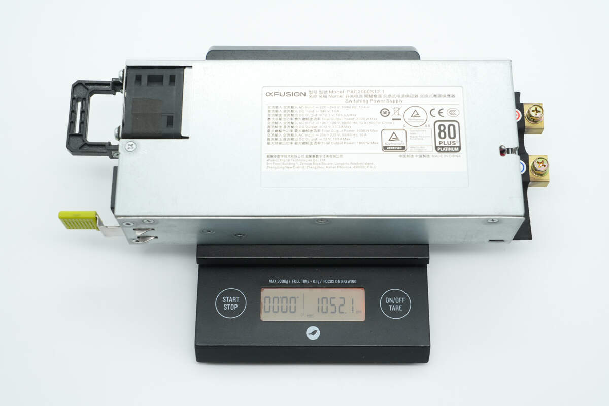
The weight is about 1052 g (2.32 lb).
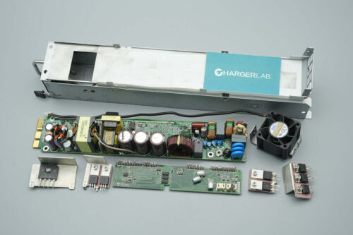
Teardown
Next, let's take it apart to see its internal components and structure.
Unscrew the screws and remove the top cover. Inside, there is a black insulating Mylar sheet.
The PCBA module is secured inside the enclosure with screws.
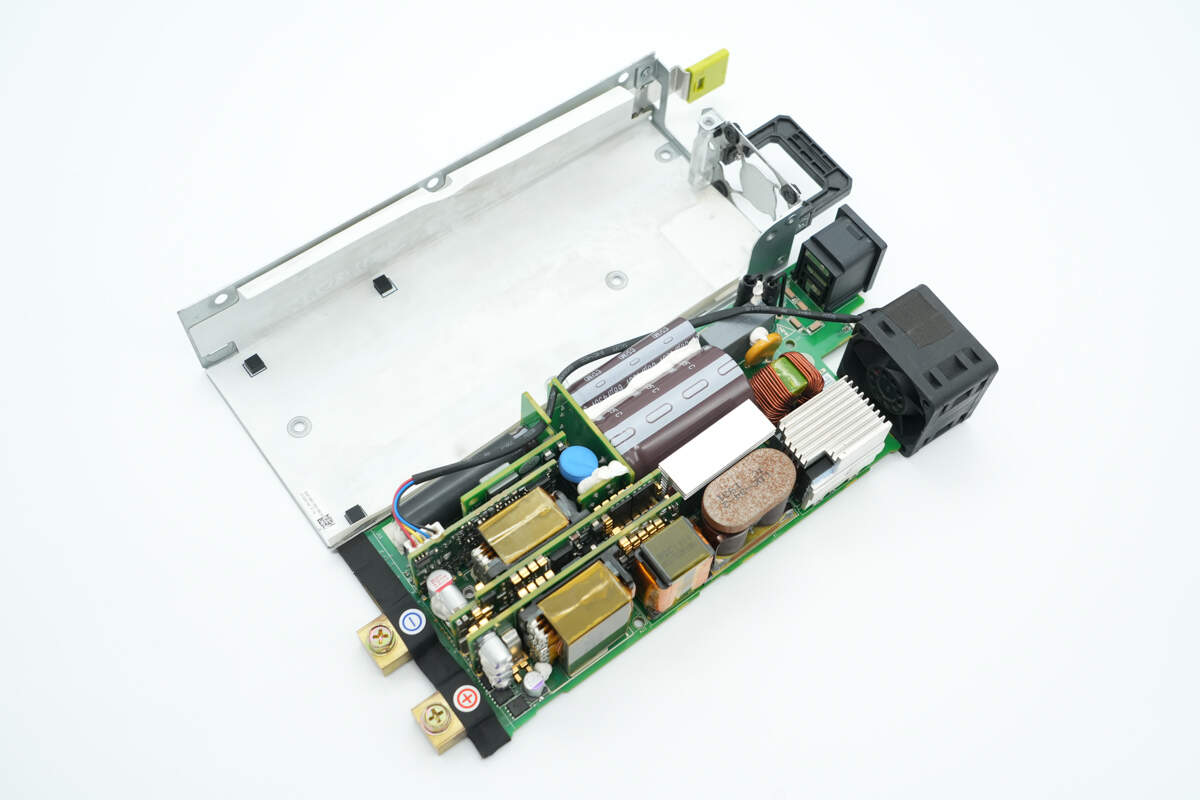
Remove the PCBA module; inside the enclosure, there is a white insulating Mylar sheet.
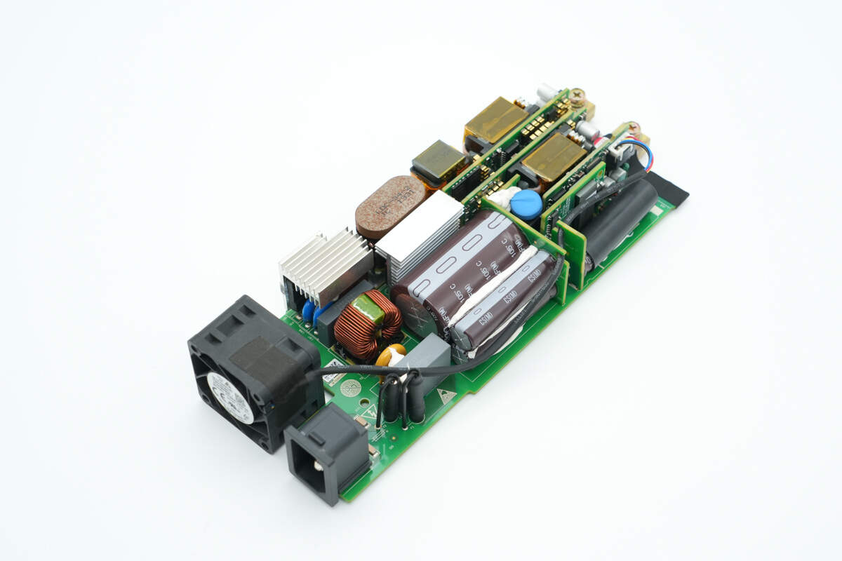
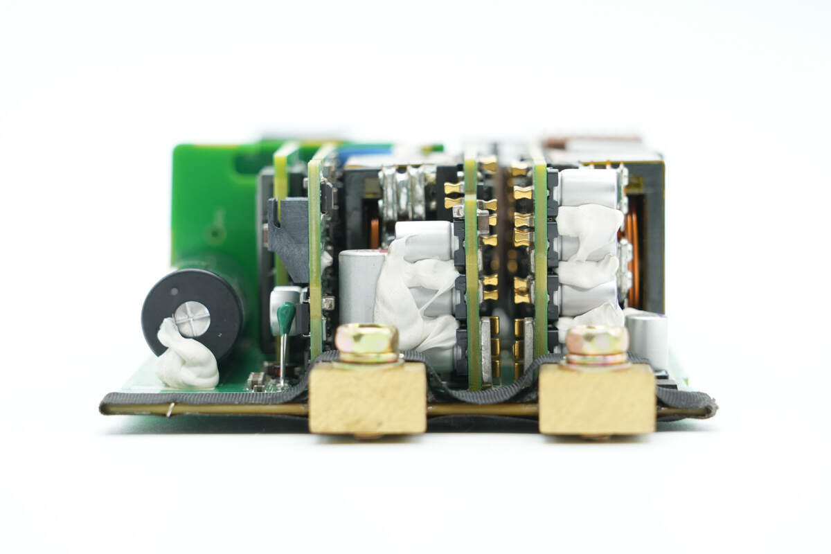
The PCBA module is composed of multiple small PCBs soldered together, and the fan wiring is insulated with heat shrink tubing.
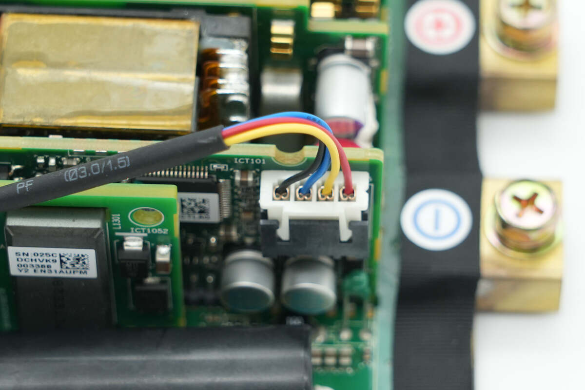
The fan is connected via a plug connector.
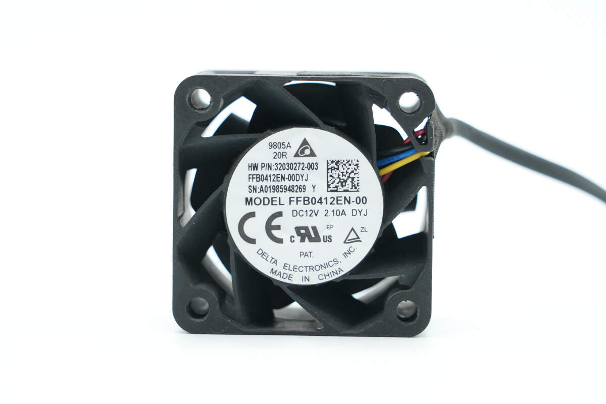
The cooling fan is from Delta, model FFB0412EN-00, rated at 12V 2.1A, made in China, and equipped with static blades.
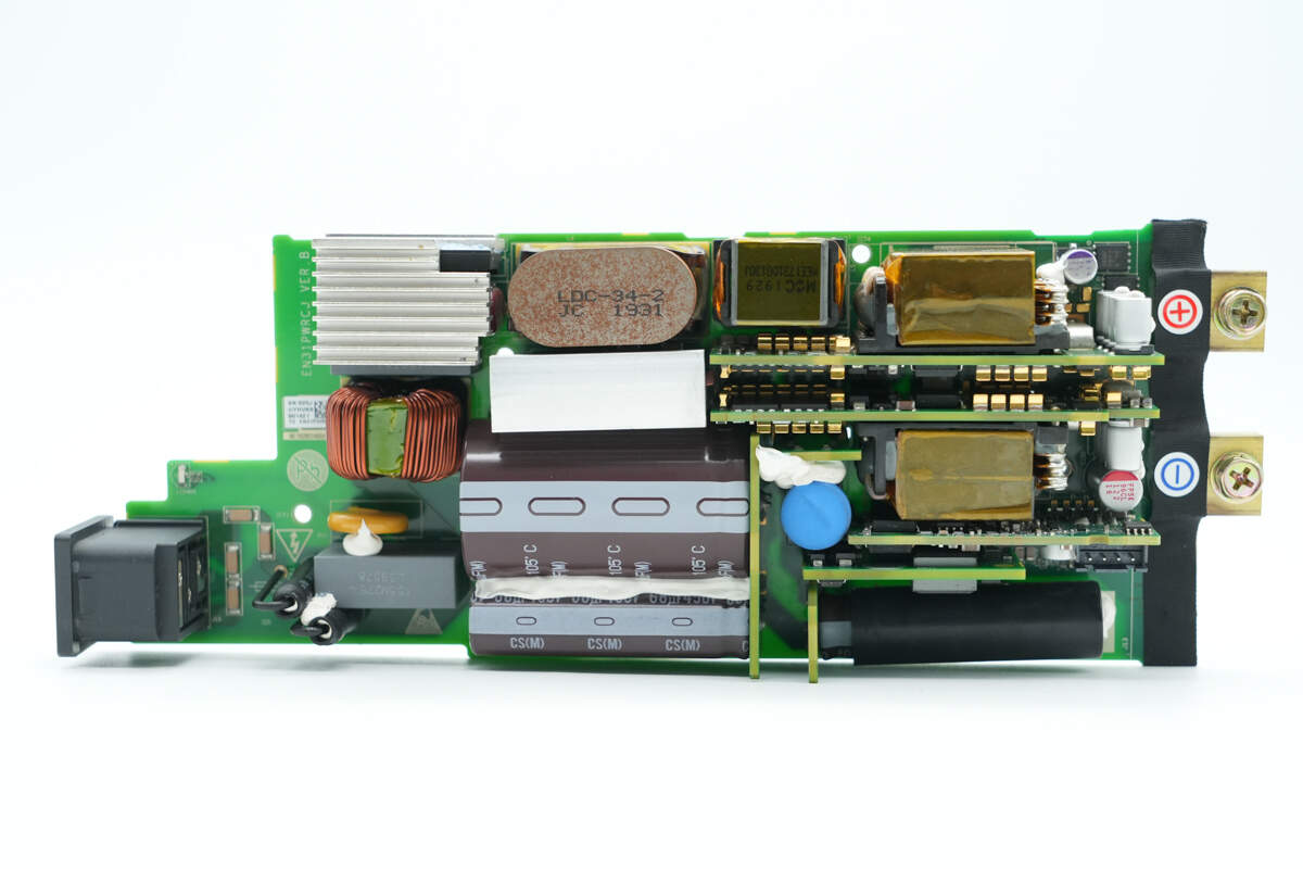
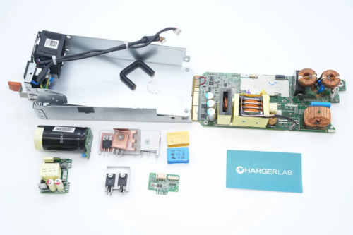
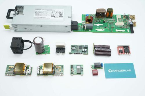
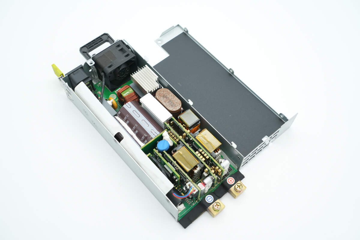
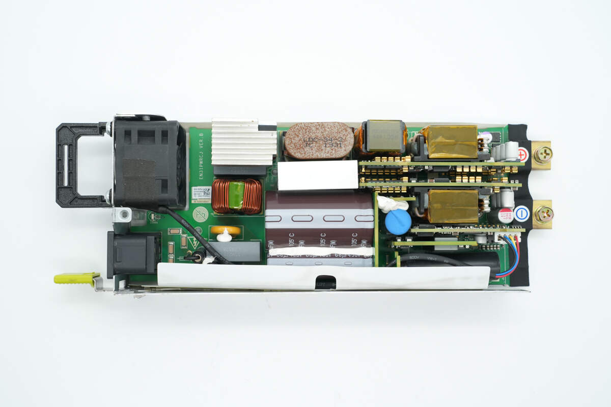
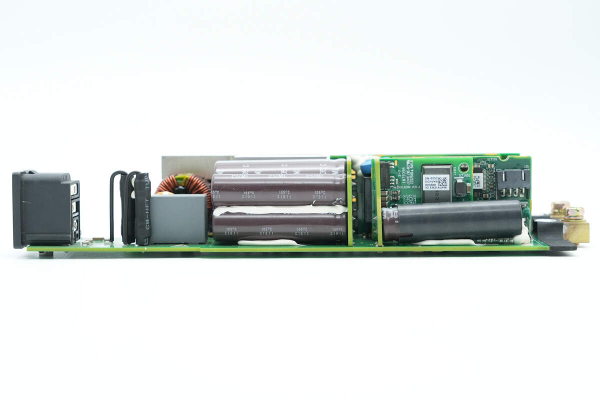
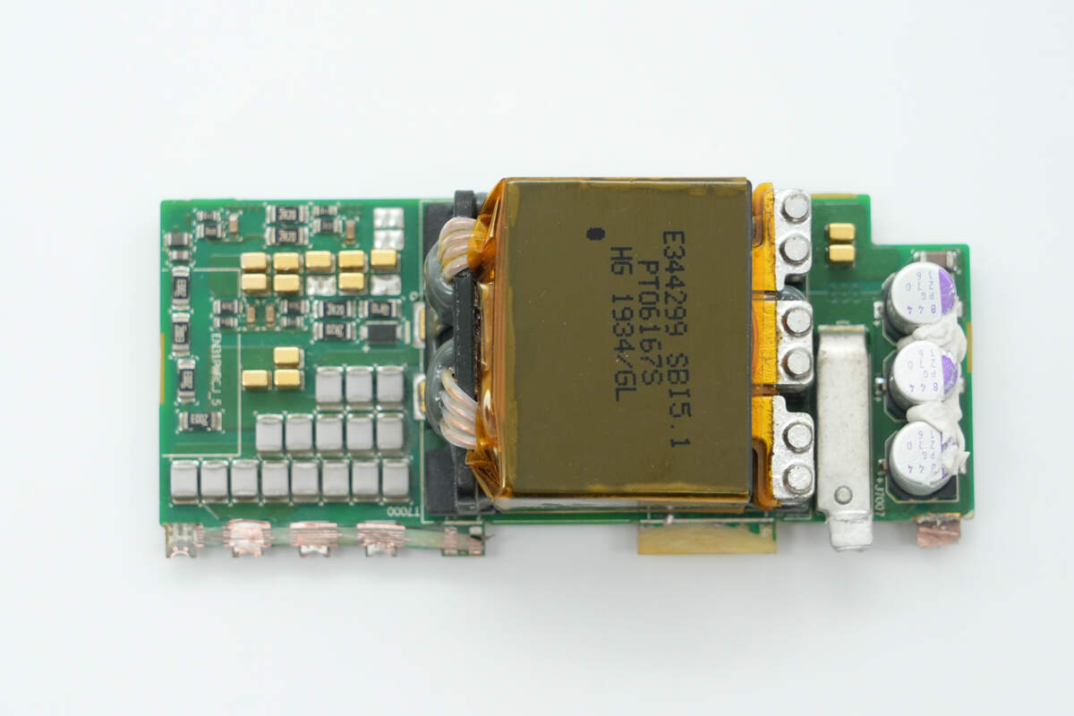
On the front side of the PCBA module, the AC input section is located at the lower left corner. It includes components such as fuses, safety X2 capacitors, varistors, common mode chokes, and bridge rectifiers. Adjacent to this area on the right are PFC boost inductors, with heatsinks mounted below that secure the PFC MOSFETs and rectifiers. At the bottom, there are high-voltage filter capacitors.
To the right, there are symmetrical LLC power modules, each on a small PCBs that contain MOSFETs, transformers, synchronous rectifiers, and filter capacitors. Below these modules on the right side are control PCBs and auxiliary power supply modules. The high-voltage filter capacitors at the bottom are insulated by heat-shrinkable tubing and are fixed in place with adhesive.
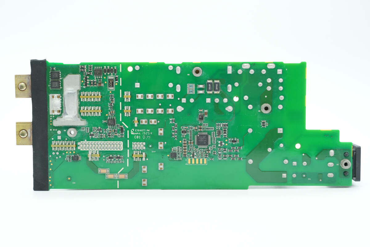
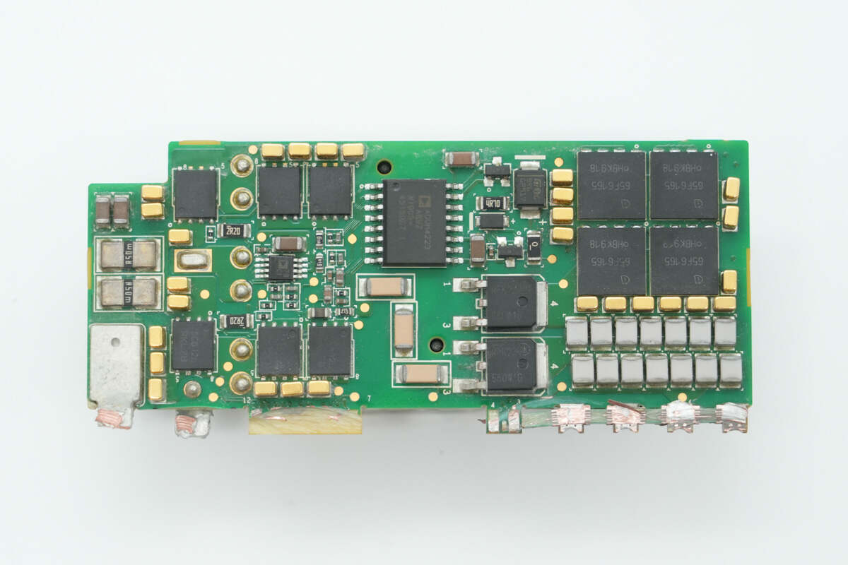
On the back side, there are PFC controllers, synchronous buck chips, and drivers. On the left side of the output, there are synchronous buck chips, op-amps, ideal diode controllers, synchronous buck converters, and power control transistors.
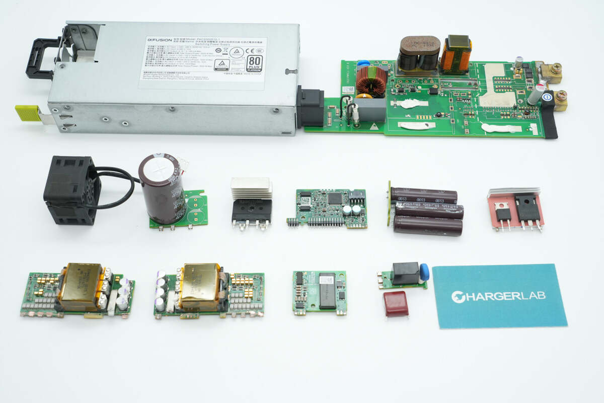
The individual small PCBs are separated. Observing the PCBA module reveals that it uses a boost PFC combined with dual LLC power stages for output, all controlled by TI controllers. ADI drivers drive the PFC MOSFETs and synchronous rectifiers, while the LLC MOSFETs use ADI isolated drivers.
At the input side, there are power sockets, fuses, safety X2 capacitors, a varistor, a common mode choke, and bridge rectifiers.
Two fuses at the input side are insulated with heat-shrink tubing.
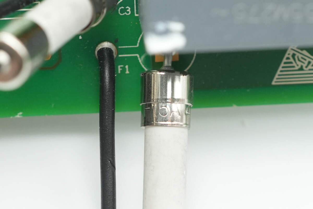
Rated at 15A.
The safety X2 capacitor is from Faratronic. 1.5μF.
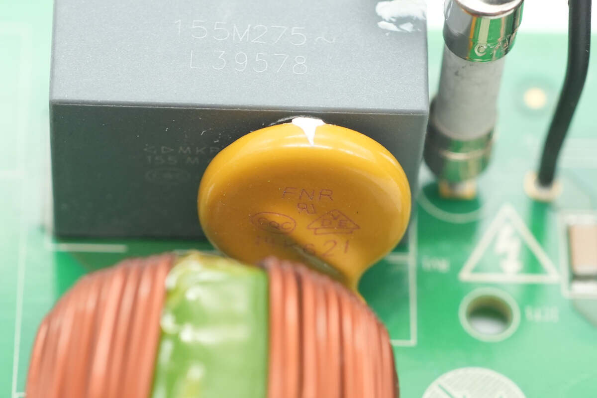
The varistor is from FNR, model FNR-14K621, used to absorb overvoltage surges.
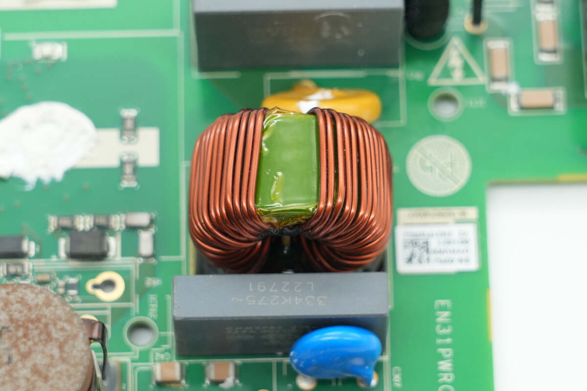
The common mode choke is wound with a magnetic ring, and it's also insulated with bakelite.
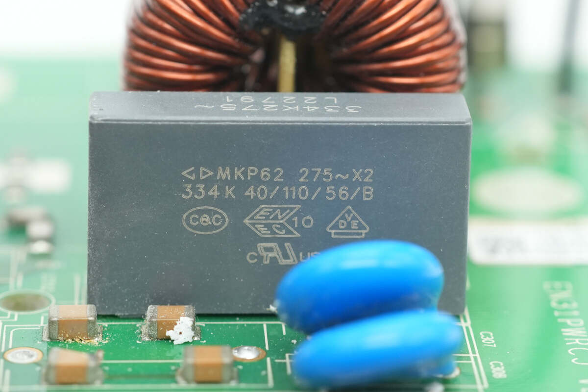
The other safety X2 capacitor is rated at 0.33μF.
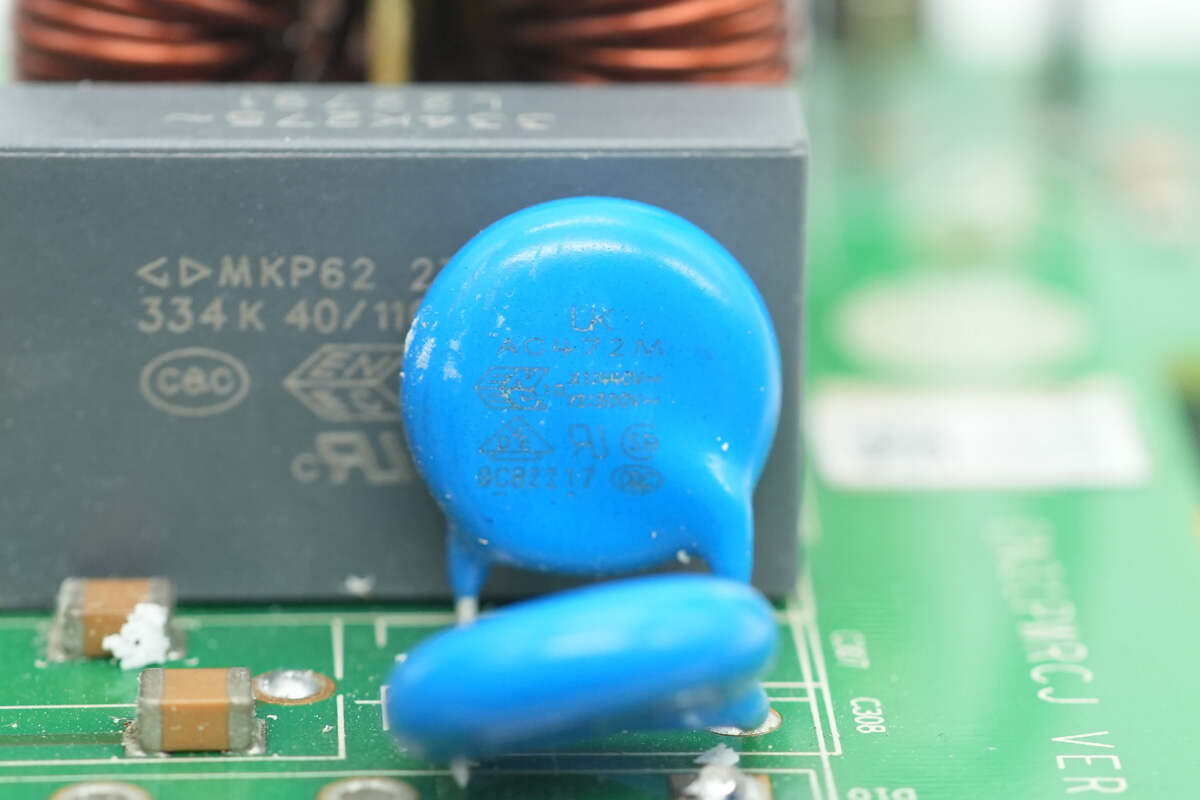
The two blue Y capacitors come from Walsin.
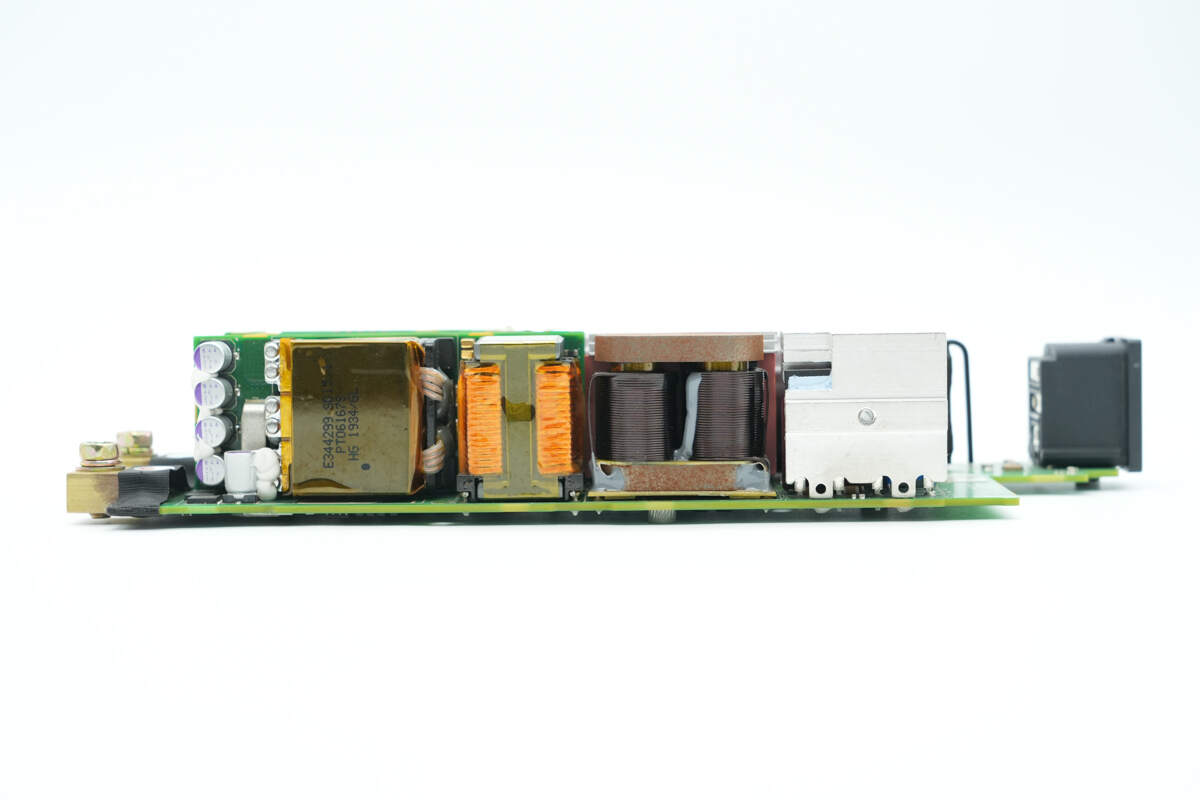
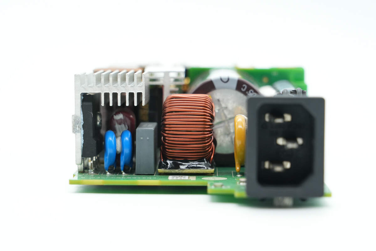
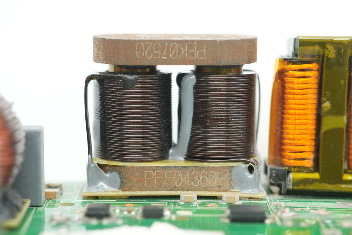
On the side of the PCBA module, there is a bridge rectifier, a PFC boost inductor, a resonant inductor, and an LLC transformer.
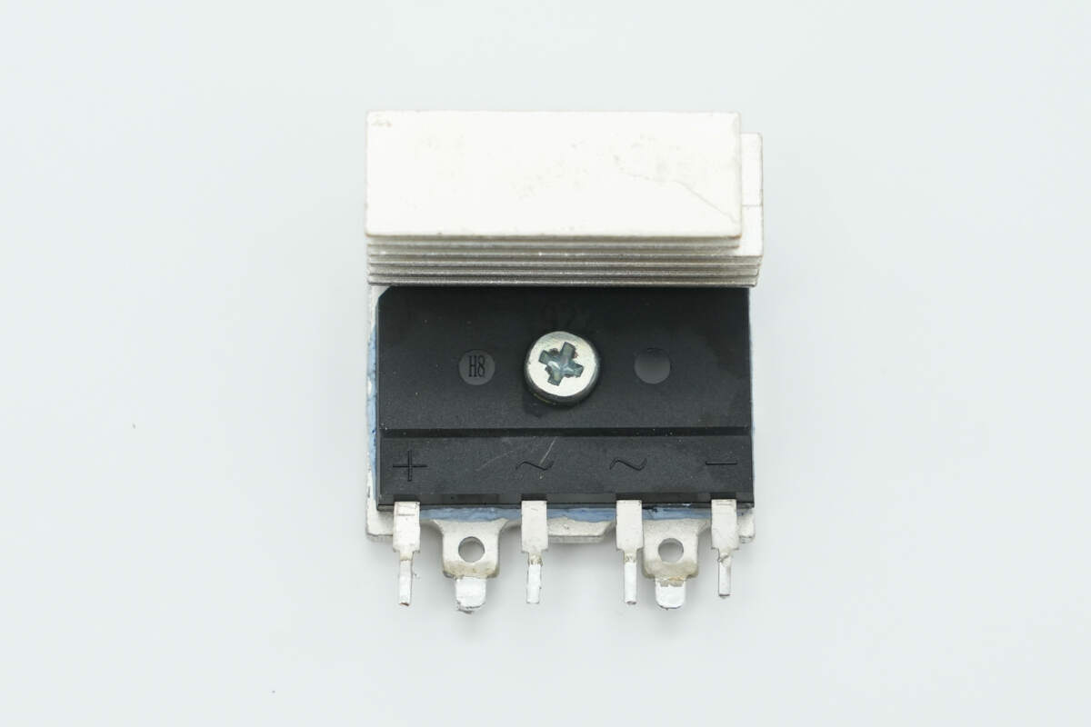
The bridge rectifier is secured to the heatsink.
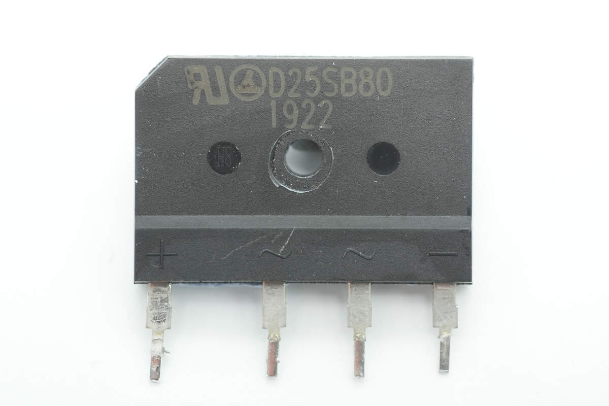
The bridge rectifier is from LRC, model D25SB80, rated at 800V 25A, and uses a D5 package.
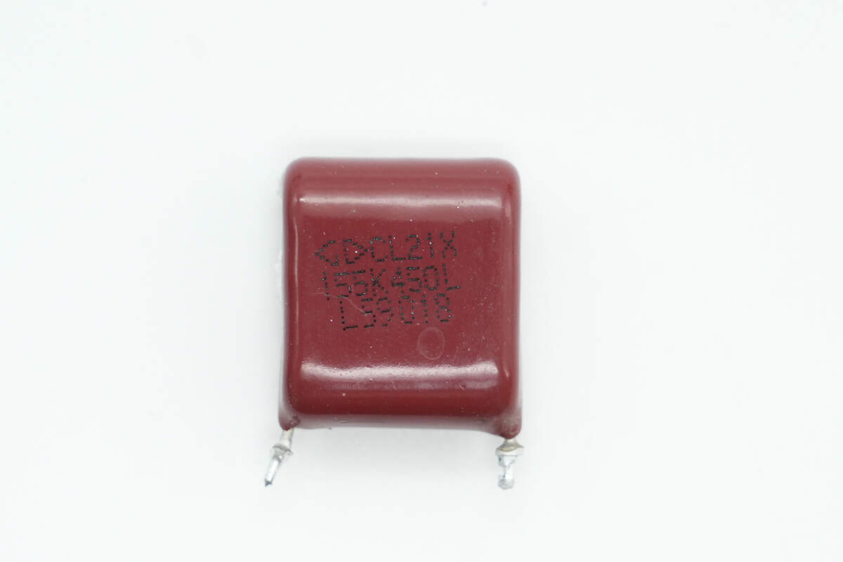
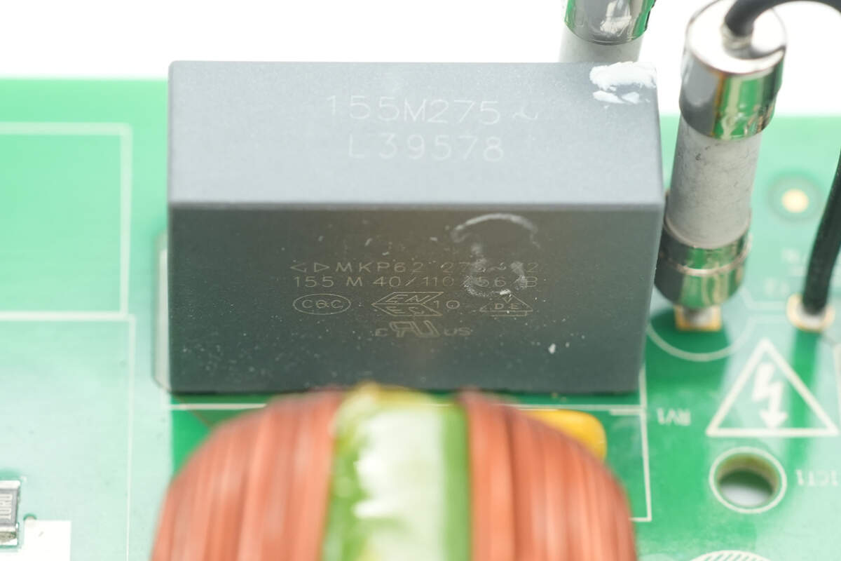
The film filter capacitor is from Faratronic. 1.5μF 450V.
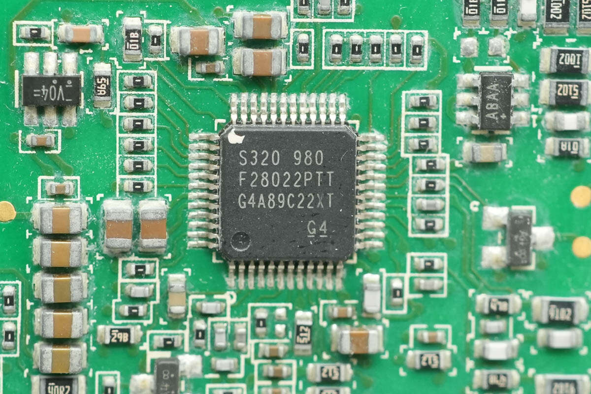
The PFC controller is from TI, model TMS320F28022. The chip features a built-in C2000 32-bit MCU with a main frequency of 50MHz, 32KB of flash memory, and 12KB of SRAM. It supports UART, SPI, and I2C interfaces and comes in an LQFP48 package.
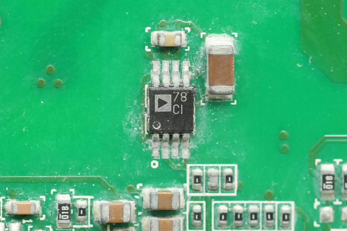
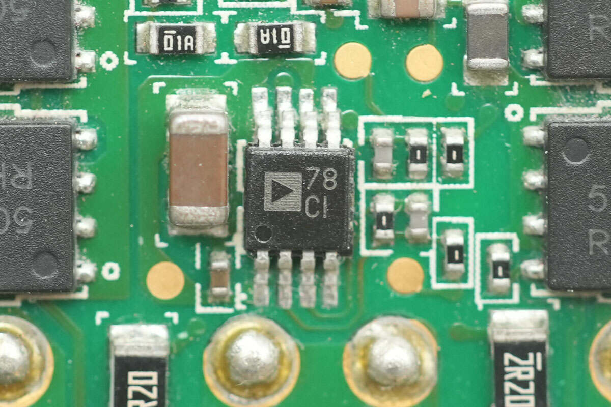
The PFC MOSFET driver is from ADI, marked with 78, model ADP3654. It is a high-speed dual-channel 4A driver featuring an industrial-standard compatible pin layout and high current driving capability. The driver comes in an MSOP8EP package.
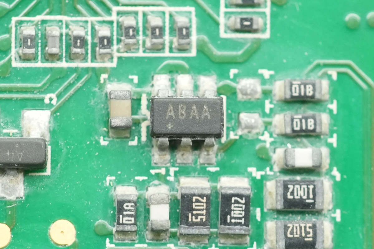
The op-amp is from ADI, marked with ABAA, model MAX4239AUT. It is an ultra-low offset, low-noise, high-precision op-amp packaged in SOT23.
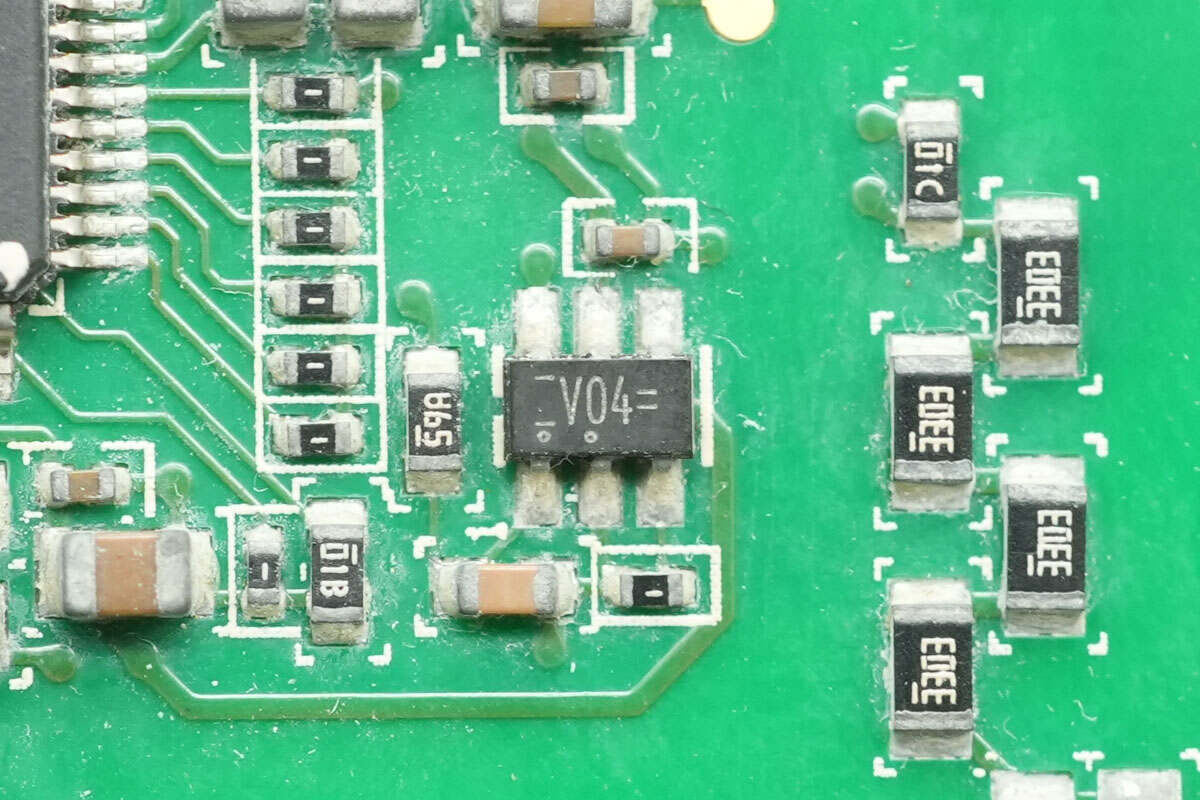
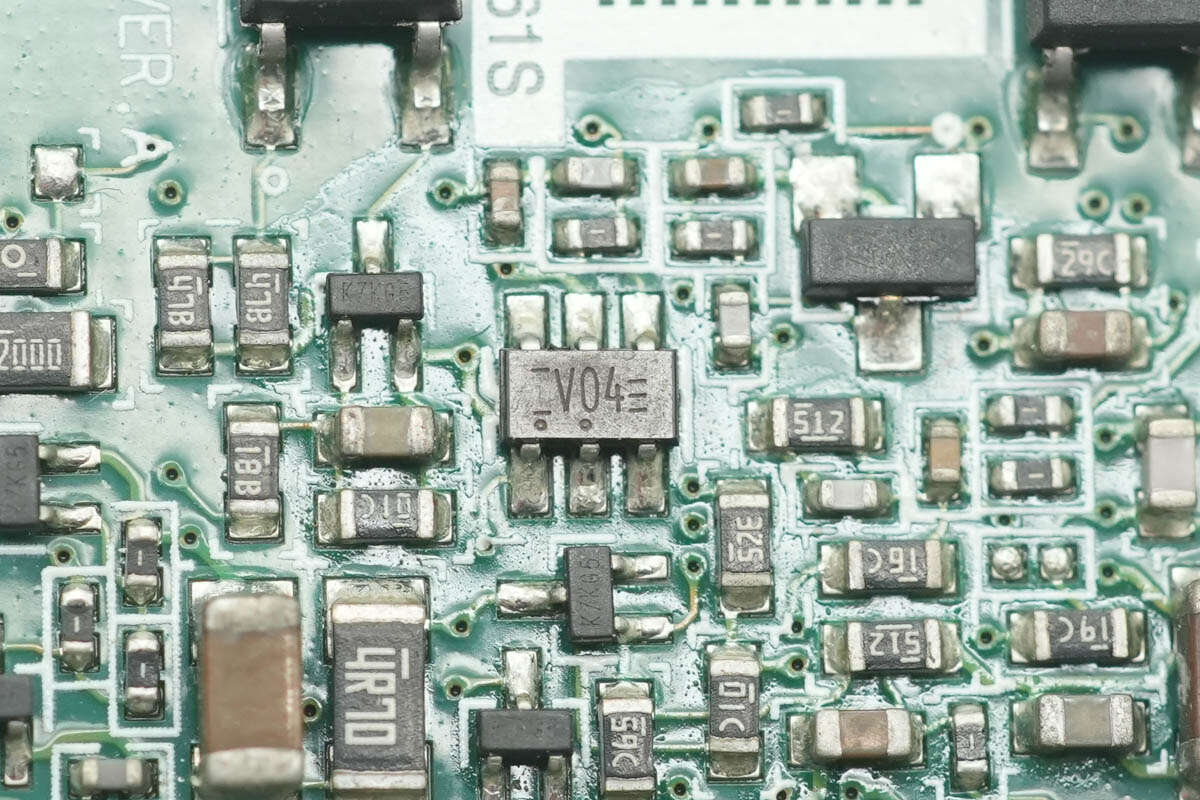
The inverter is from Nexperia, marked with "V04," model 74LVC1G04GV, and comes in an SOT753 package.
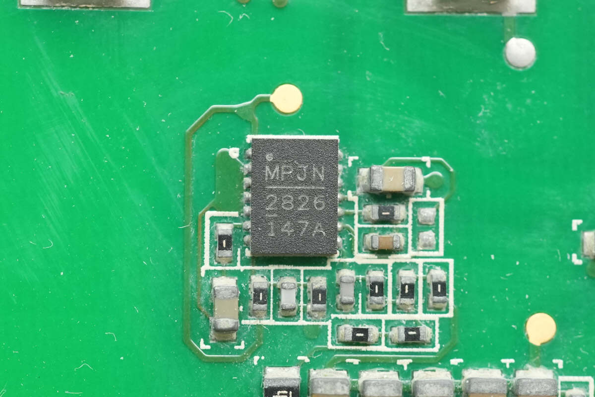
The synchronous buck chip is from MPS, model MPQ28261. It is a synchronous buck converter with 21A input and 3A output current. The chip integrates MOSFETs internally, operates at a switching frequency of 500kHz, and comes in a QFN14 package.
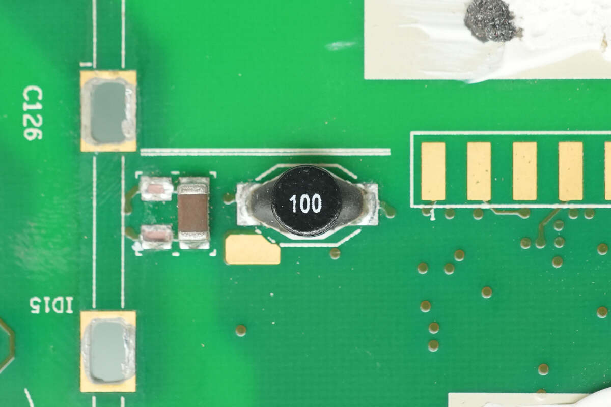
Close-up of the 10μH buck inductor.
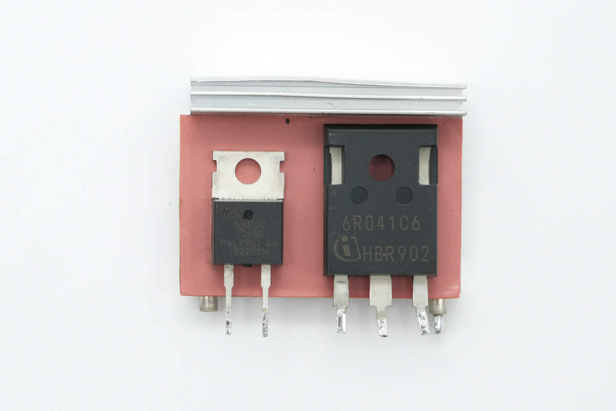
The PFC MOSFET and PFC rectifier are mounted on the heatsink.
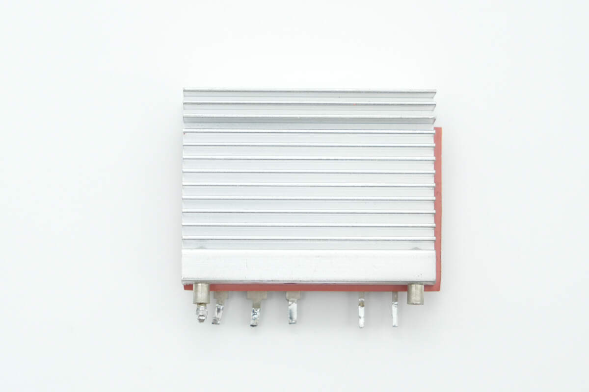
The back of the heatsink is slotted to enhance heat dissipation.
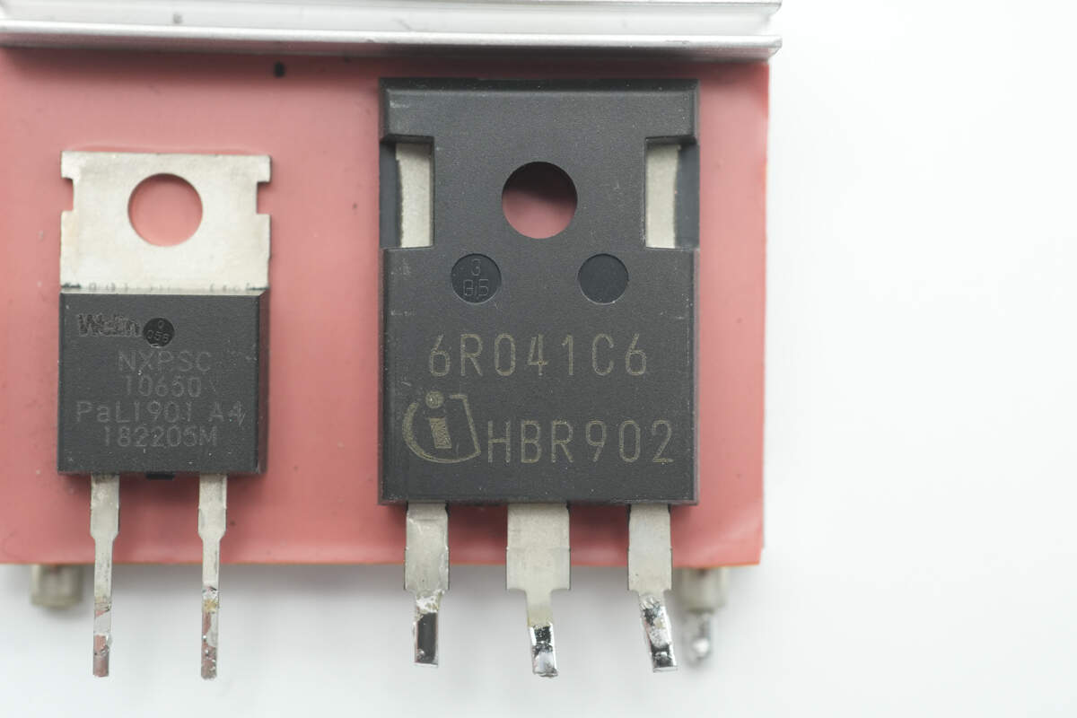
The PFC MOSFET is from Infineon, marked with 6R041C6, model IPW60R041C6. It is an NMOS with a voltage rating of 650V and an on-resistance of 41mΩ, packaged in TO-247.
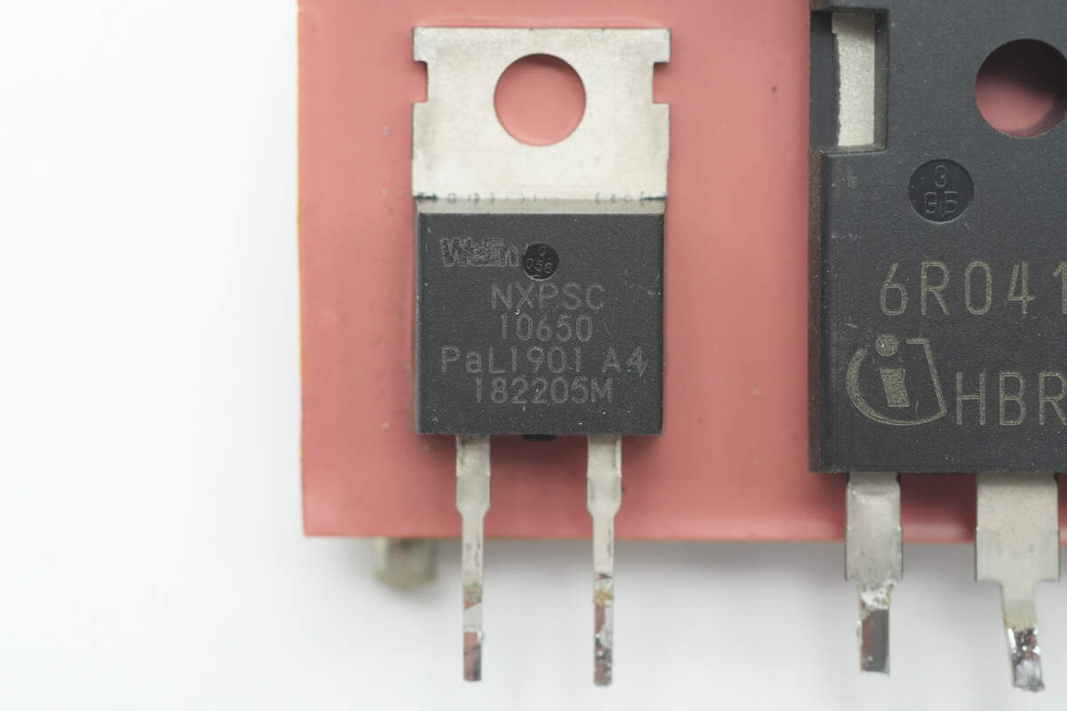
The SiC diode is from RePower, model NXPSC10650, rated at 650V 10A, and packaged in TO-220-2L.
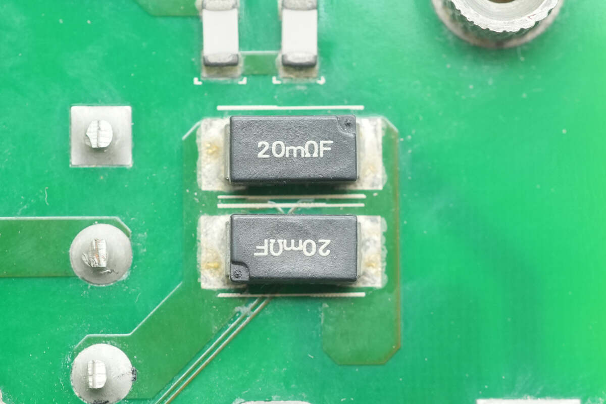
Two 20mΩ resistors are connected in parallel to sense the current of the PFC MOSFET.
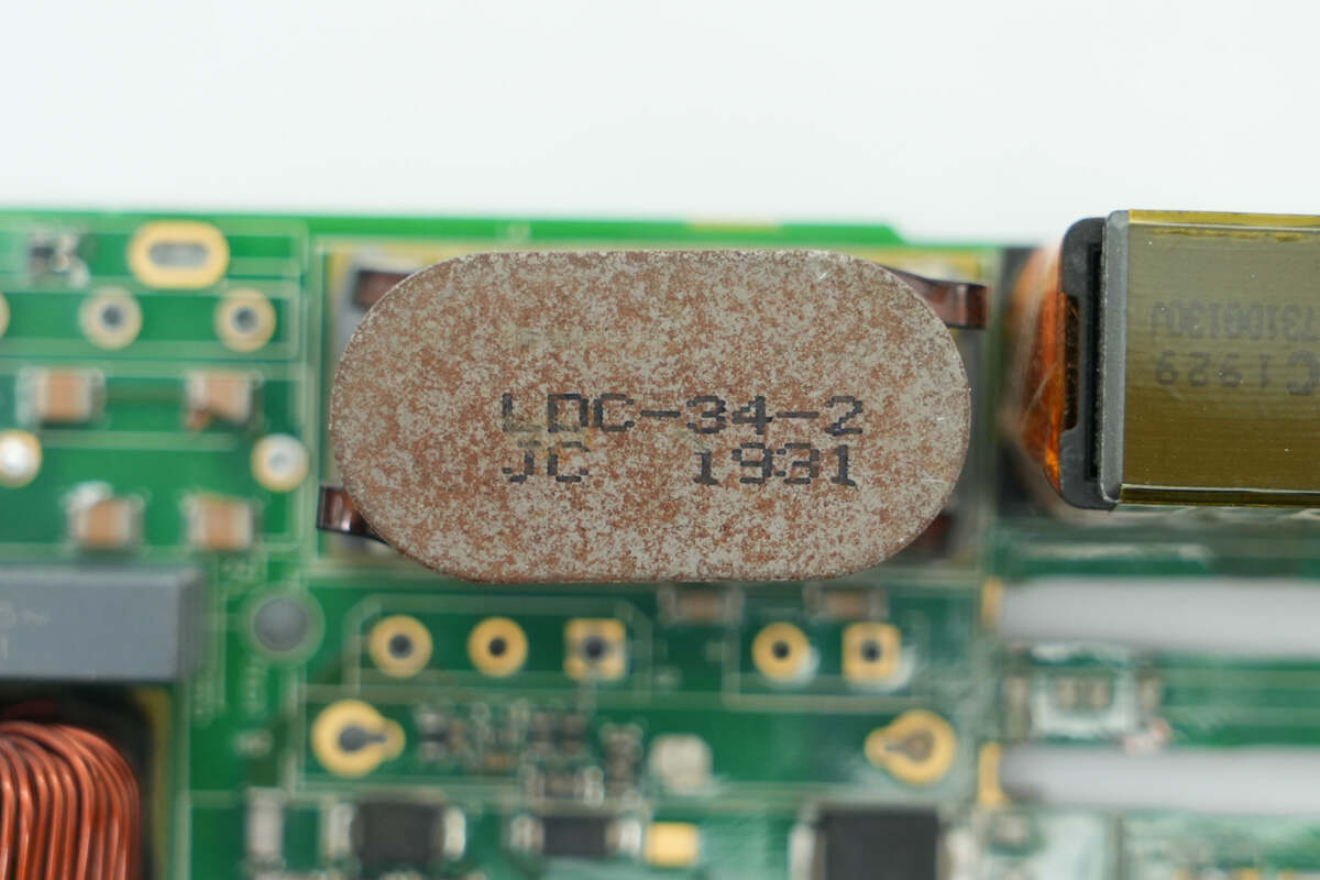
Close-up of the PFC inductor core.
The PFC inductor is wound with flat copper wires, and it's also insulated with bakelite.
There are high-voltage filter capacitors on this side.
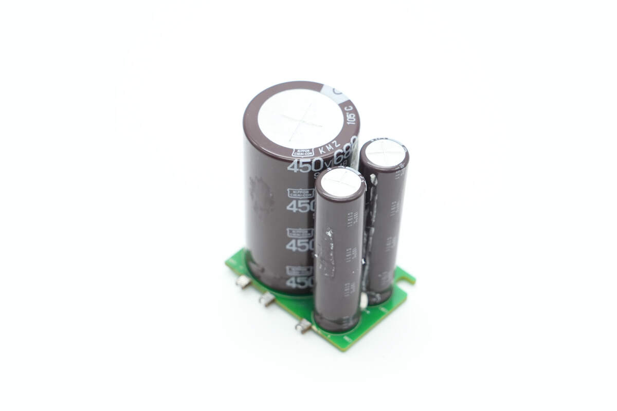
The high-voltage filter capacitors are soldered onto a small PCB.
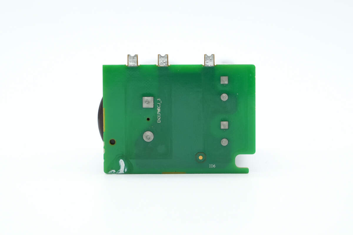
There are no components on the back.
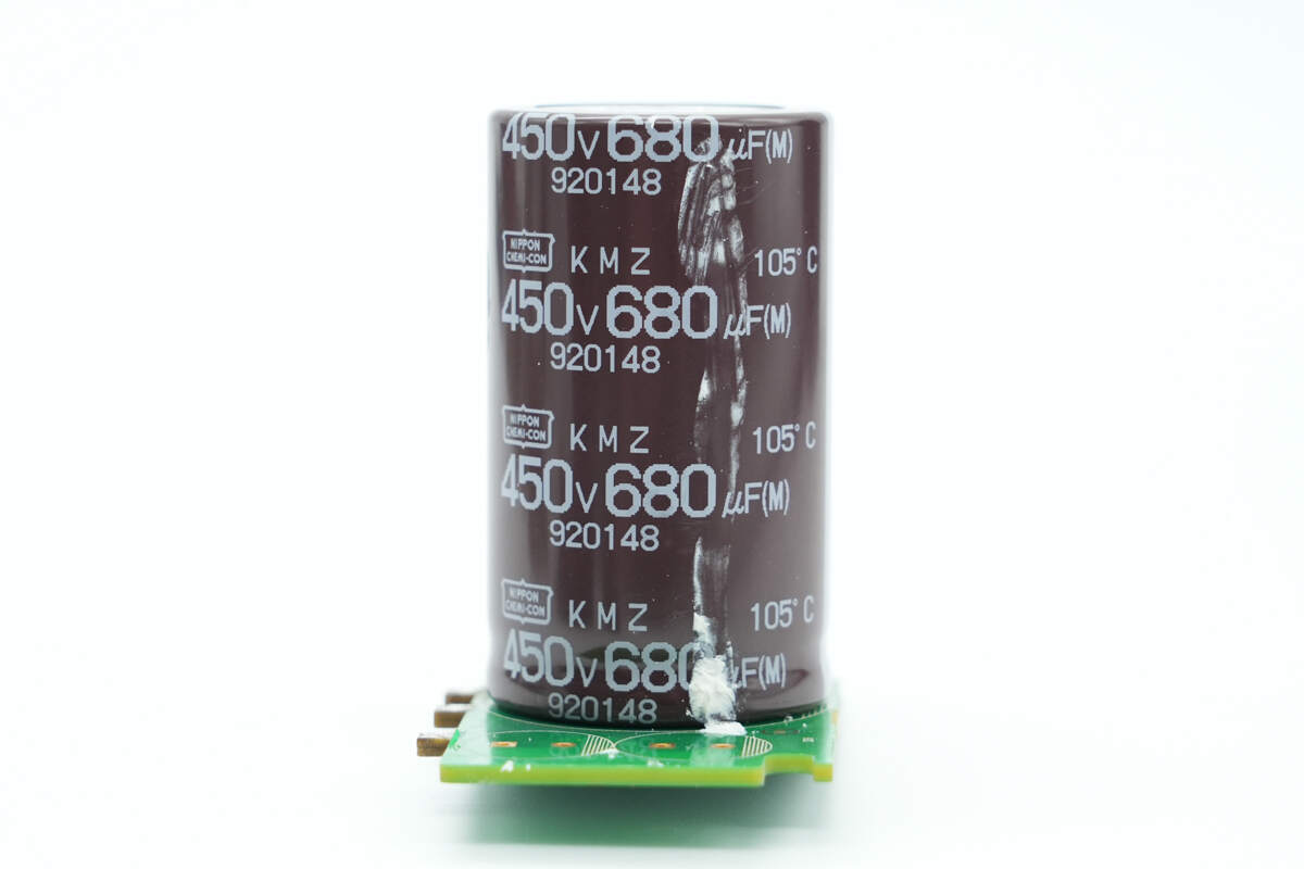
The high-voltage filter capacitor is from NCC, rated at 450V 680μF.
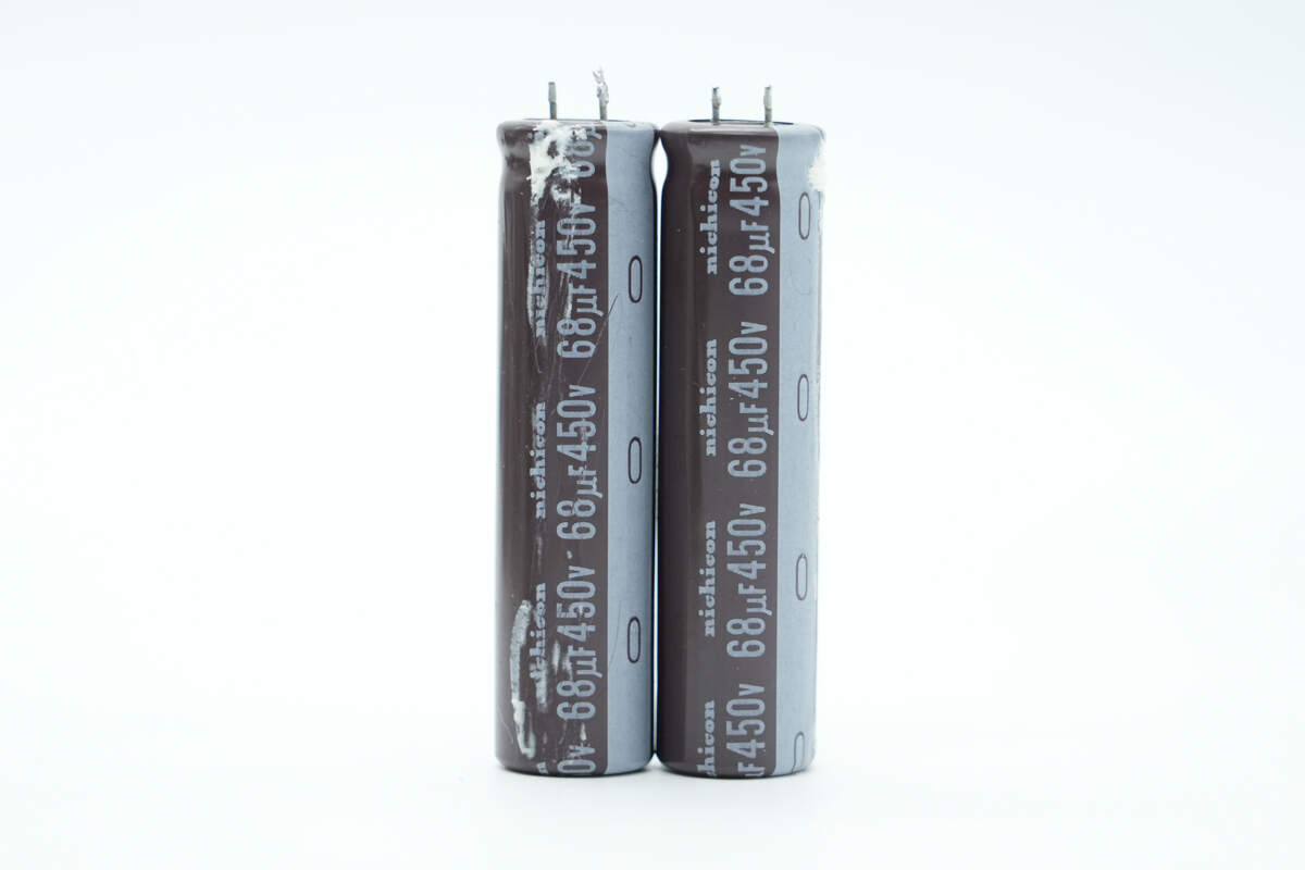
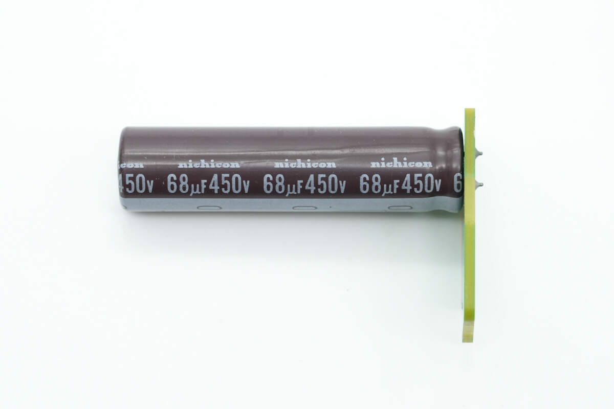
The other two electrolytic capacitors are from Nichicon, each rated at 68μF 450V.
A filter capacitor of the same model is also soldered on another small PCB.
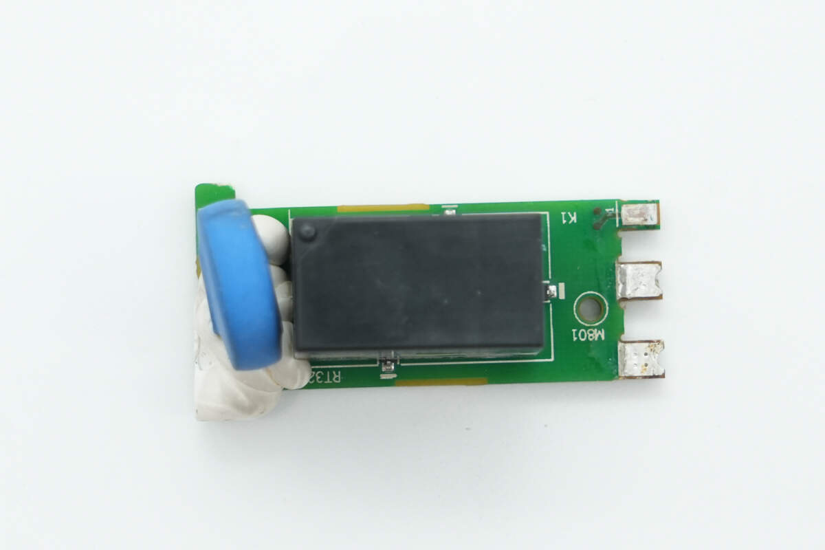
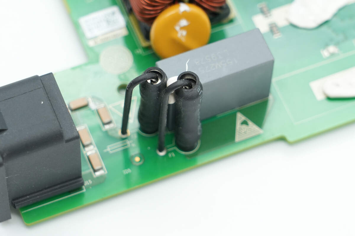
There is a thermistor and a relay on this small PCB.
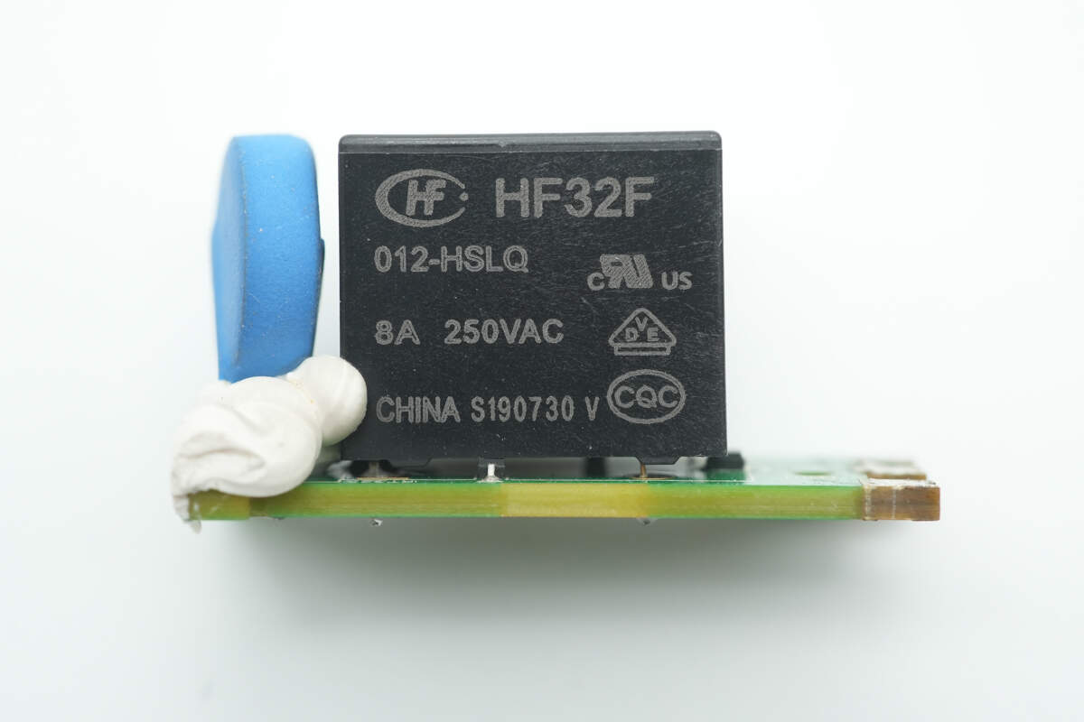
The relay is from HONGFA, model HF32F/012-HSLQ. It is an ultra-compact medium-power relay with a single normally open contact, rated at 8A 250V, and operates at a coil voltage of 12V.
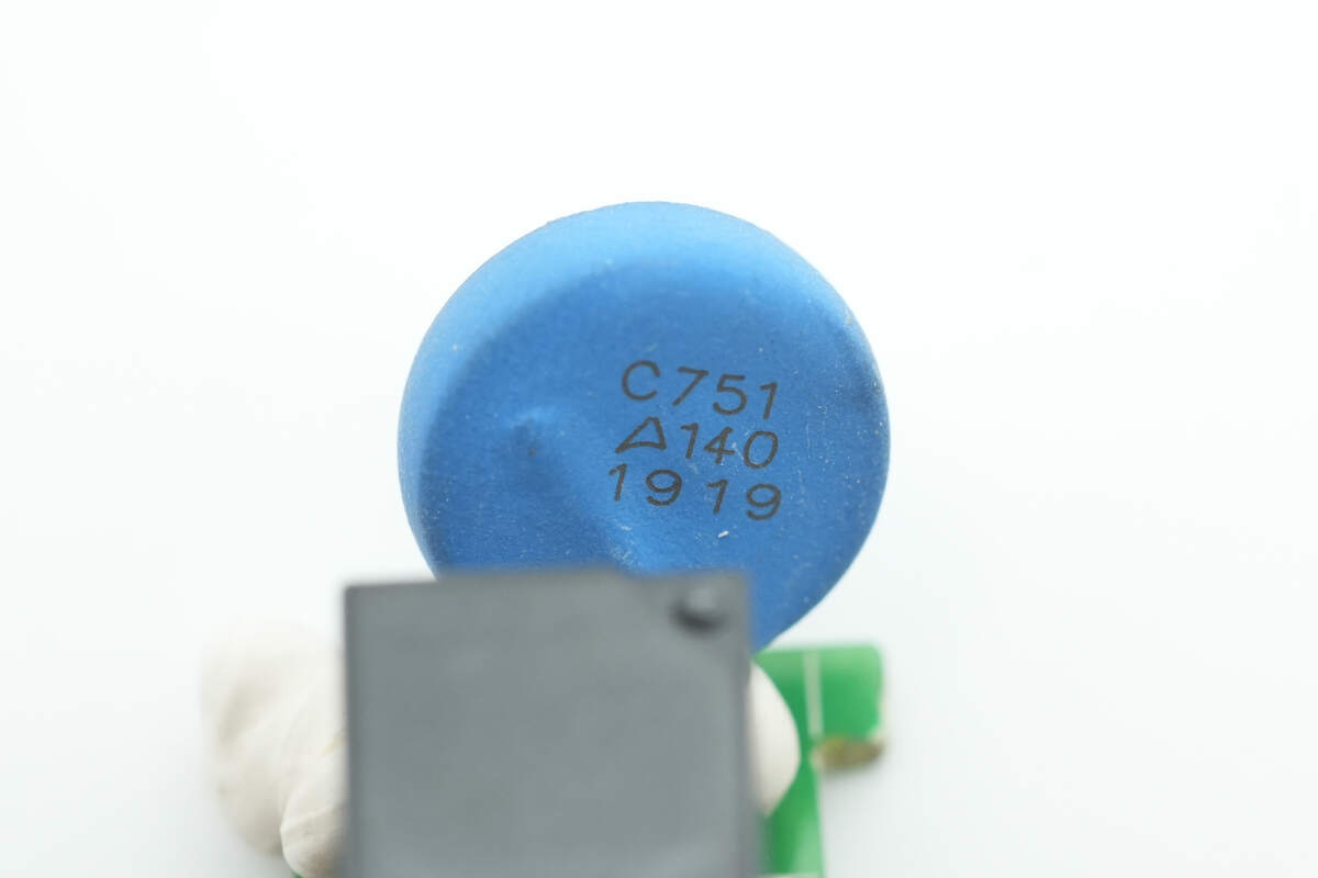
The blue thermistor is from TDK, with adhesive applied at the bottom for reinforcement.
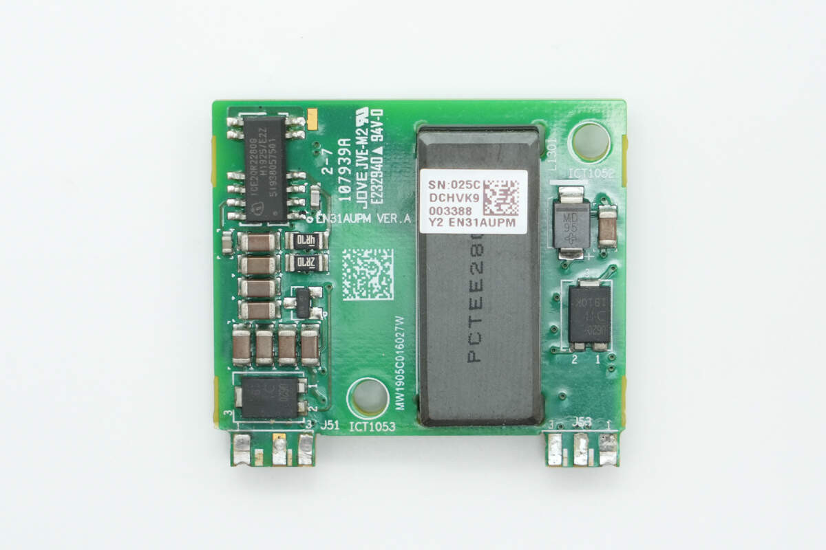
On one side of the auxiliary power PCB, there is a primary master control chip, a planar transformer, and a rectifier.
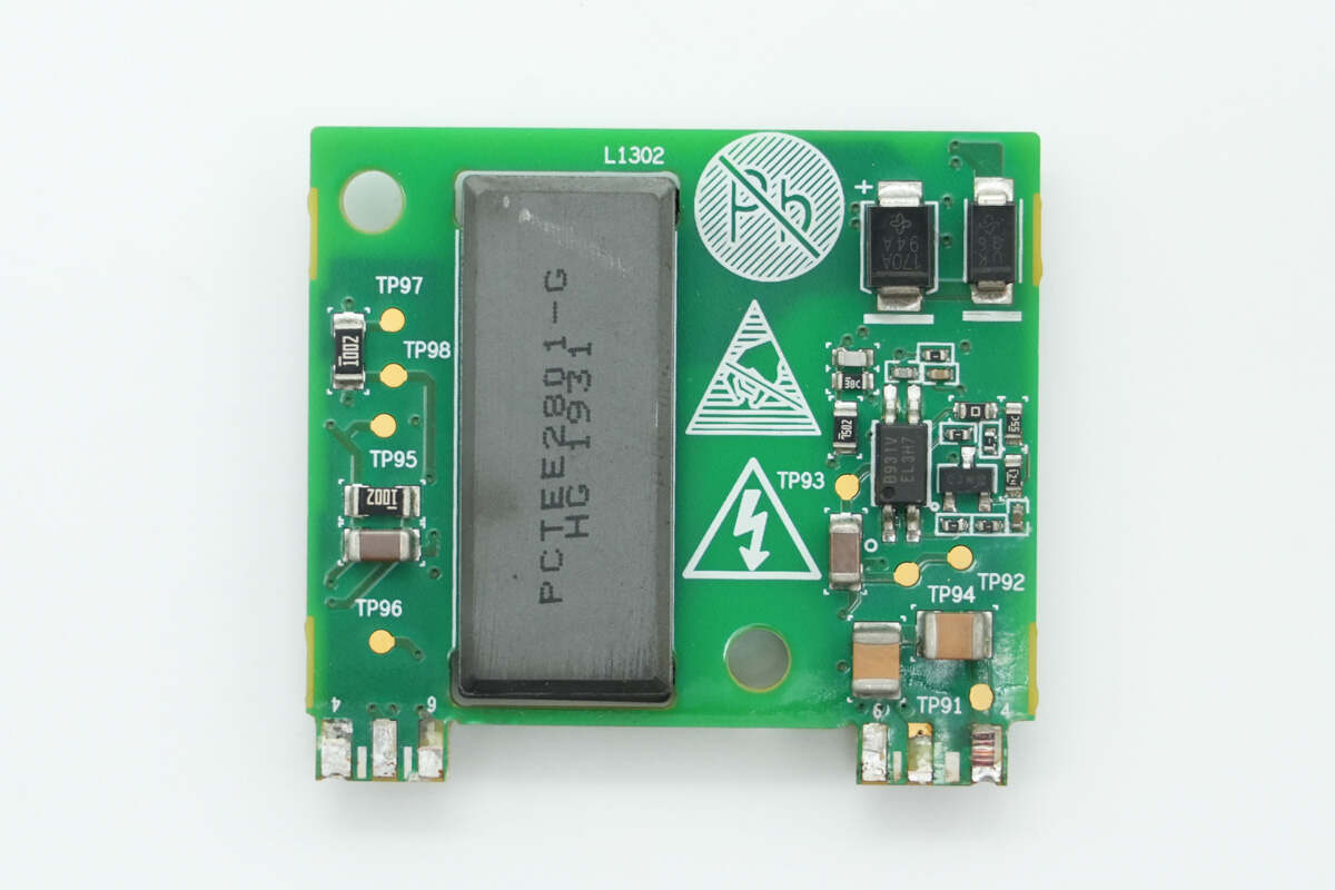
On the other side, there is a feedback optocoupler and diodes.
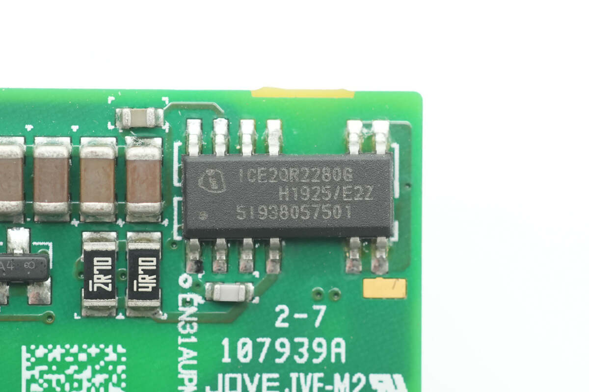
The primary master control chip is from Infineon, model ICE2QR2280G. It integrates an 800V MOSFET and supports 30W output power under wide voltage input. The chip comes in a DSO-12 package.
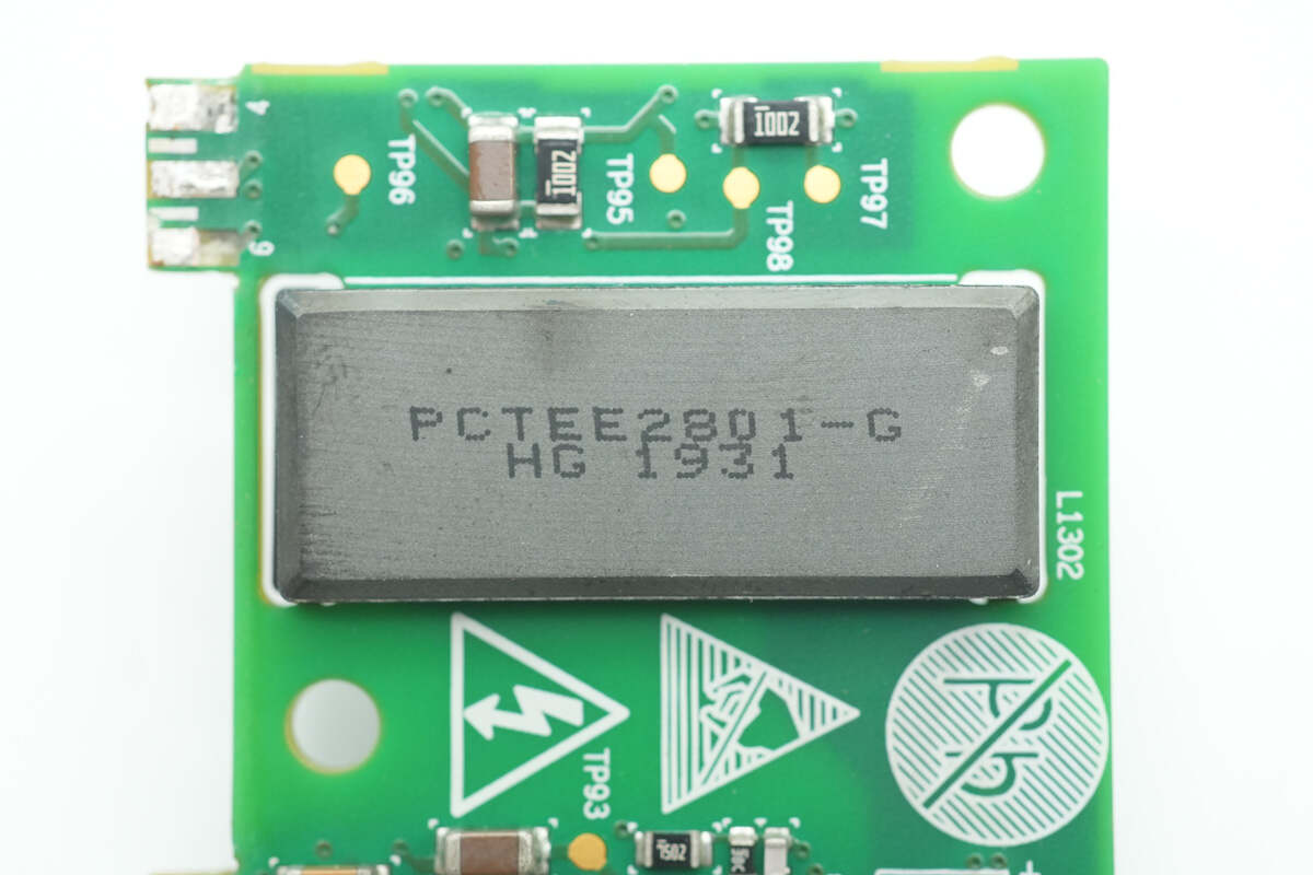
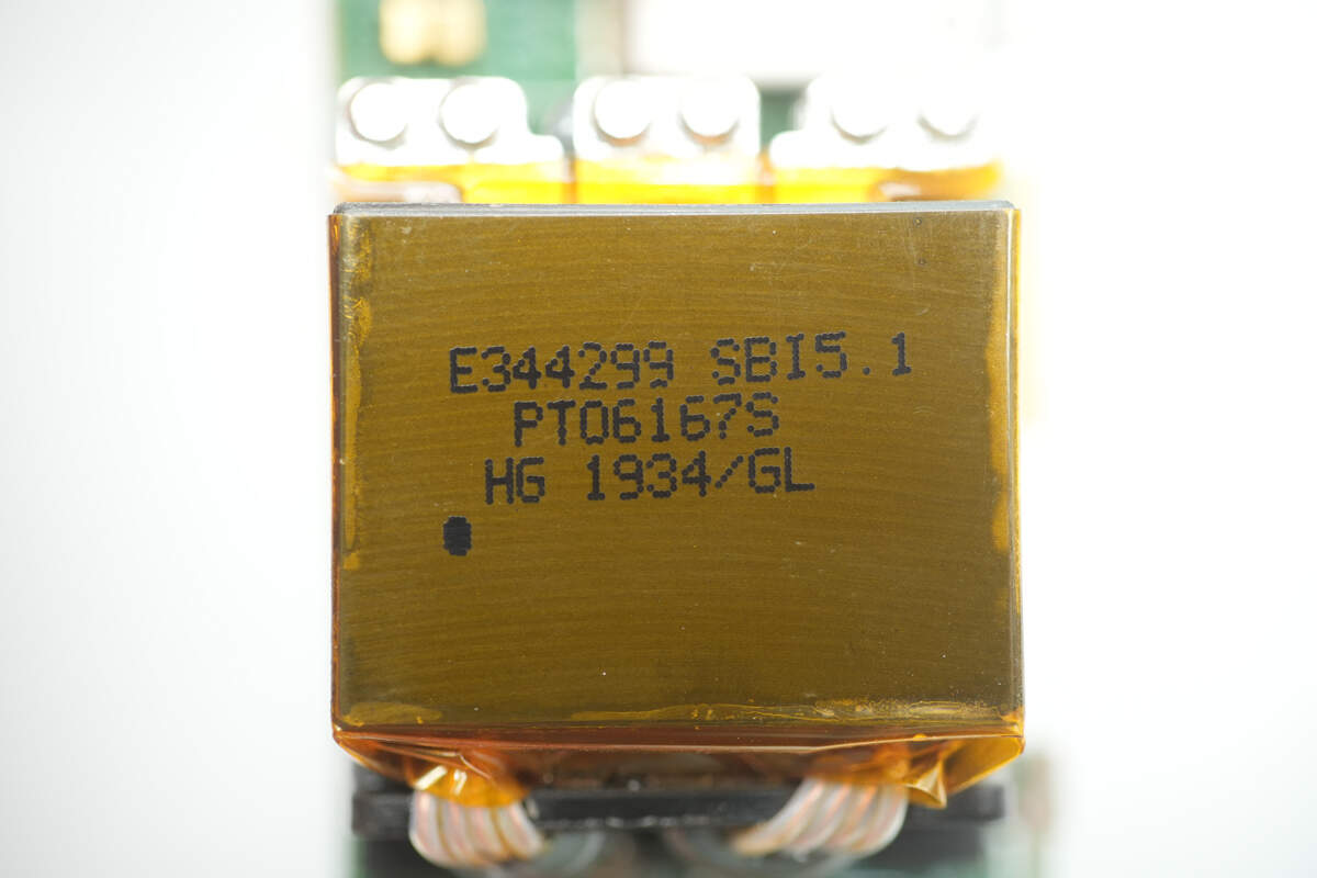
Close-up of the planar transformer.
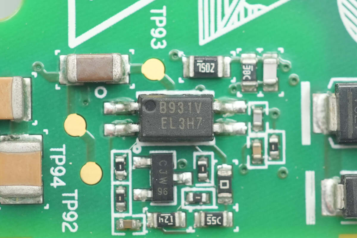
The feedback optocoupler is from Everlight, model EL3H7, used for output voltage feedback.
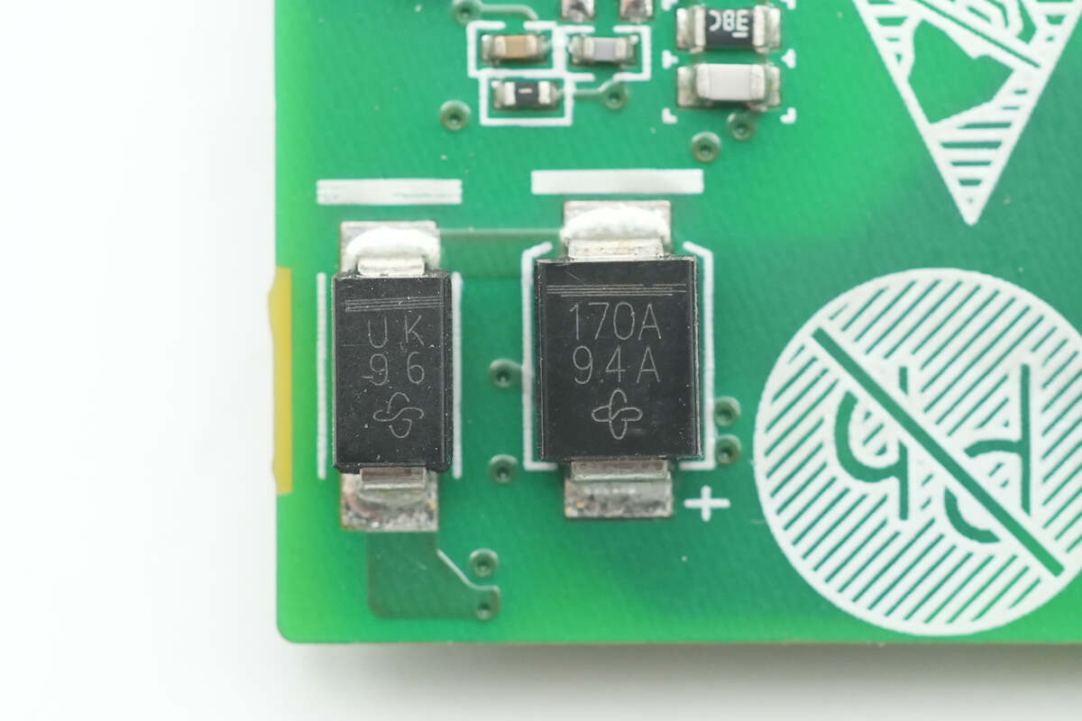
The ultrafast diode on the left is from VISHAY, marked with UK, model US1K, rated at 800V 1A, and packaged in SMA. The TVS on the right is also from VISHAY, marked with 170A, model P6SMB170A, with a working voltage of 145V, and packaged in SMB.
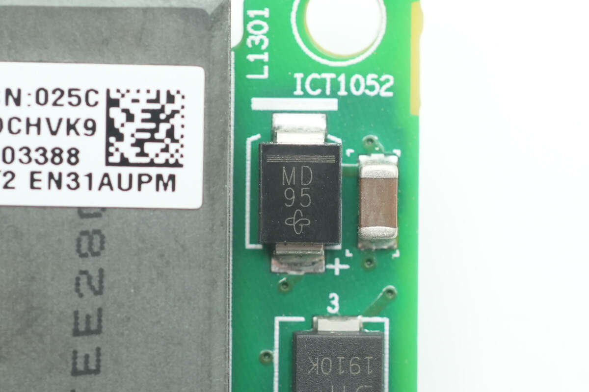
The ultrafast recovery diode is from VISHAY, marked with "MD," model MURS120-M3, rated at 200V 1A, and packaged in SMC.
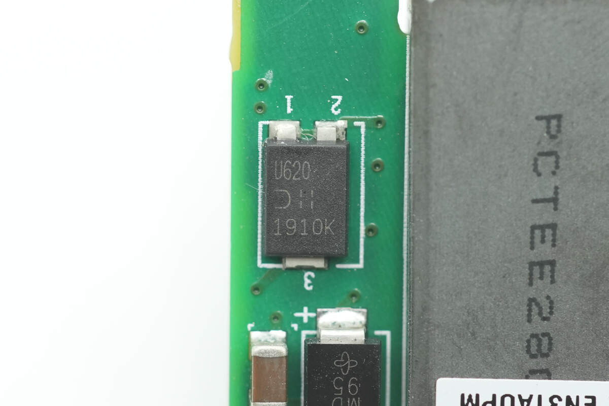
This ultrafast recovery diode is from DIODES, model PDU620, rated at 200V 6A, and packaged in PowerDI5.
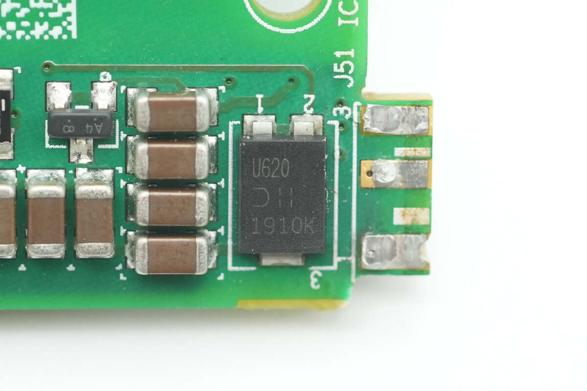
The other diode has the same model number.
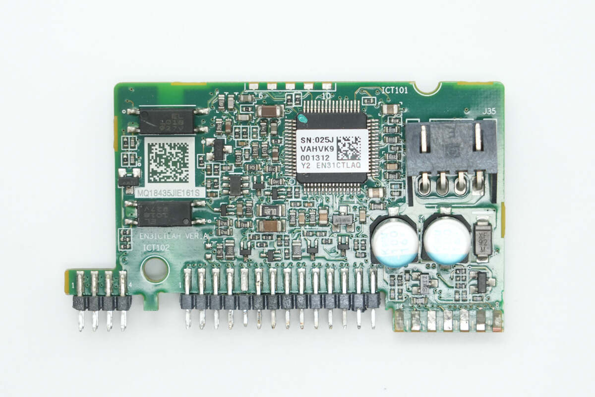
The front side of the LLC control PCB has a controller, a connector socket, and communication optocouplers.
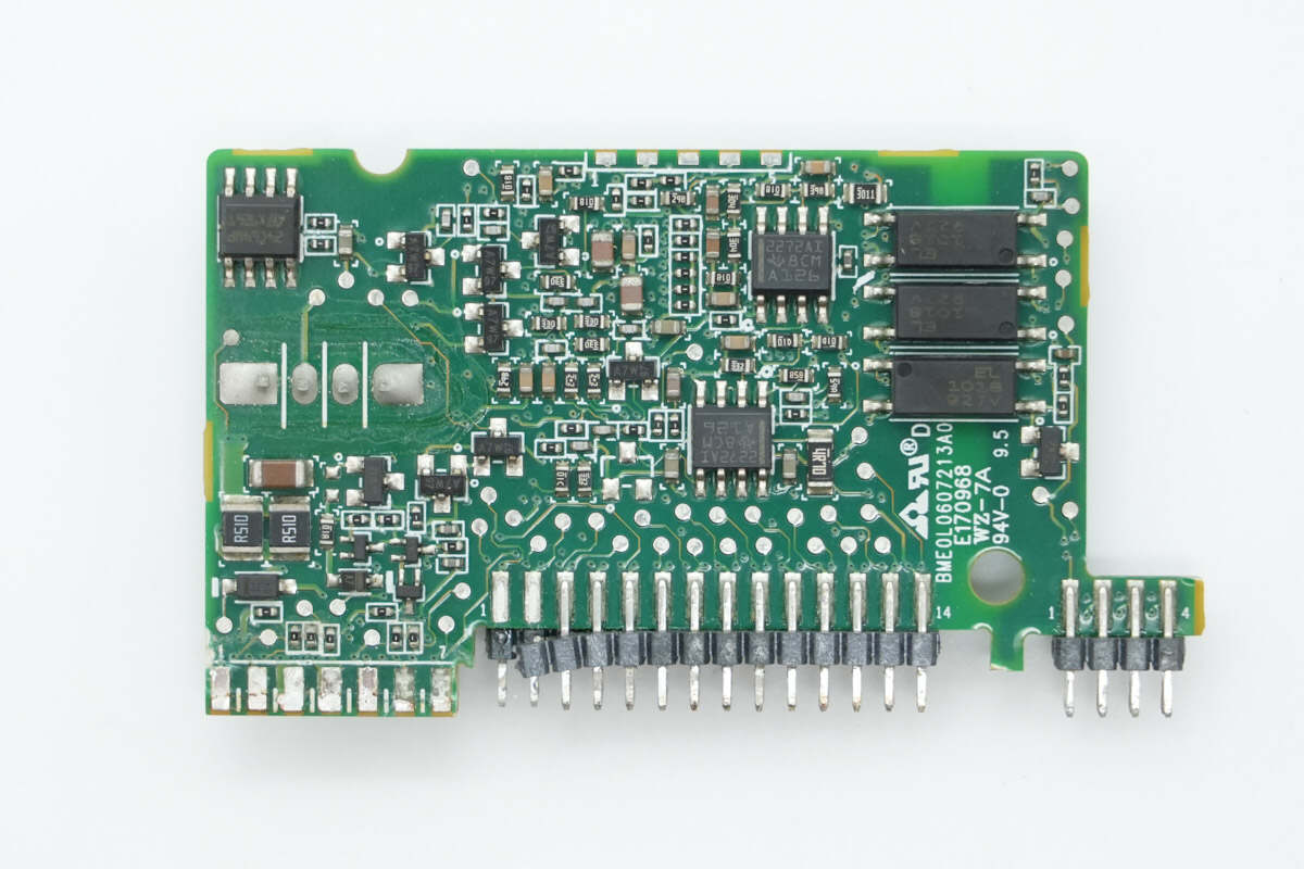
The back side has op-amps, a memory chip, and communication optocouplers.
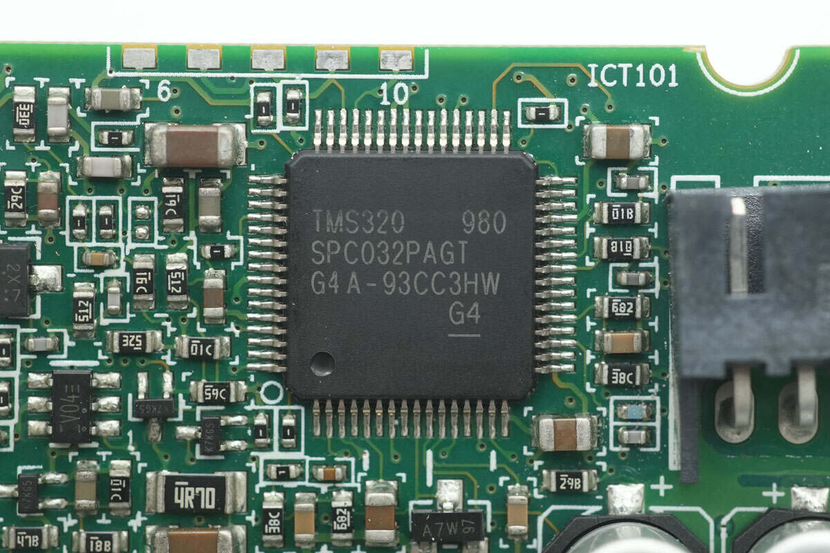
The LLC controller is from TI, marked with TMS320 980 SPC032PAGT. It is used for half-bridge LLC control and synchronous rectification control, and comes in an LQFP64 package.
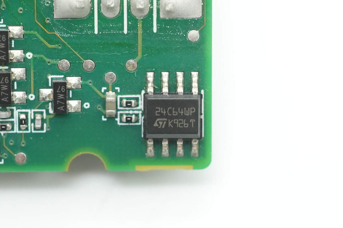
The memory chip is from STMicro, model M24C64-W, with a capacity of 8KB, and packaged in SO8.
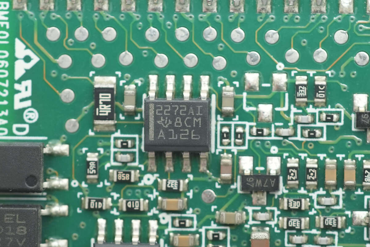
The dual op-amp is from TI, model TLC2272A. It is a dual-channel, low-noise, rail-to-rail operational amplifier, and comes in an SOIC-8 package.
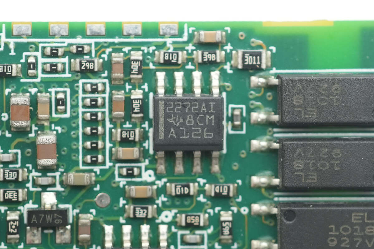
The other dual op-amp is the same model.
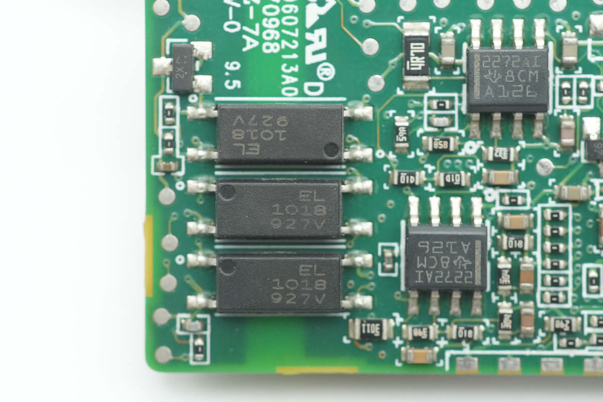
Three Everlight EL1018 optocouplers are used for communication isolation.
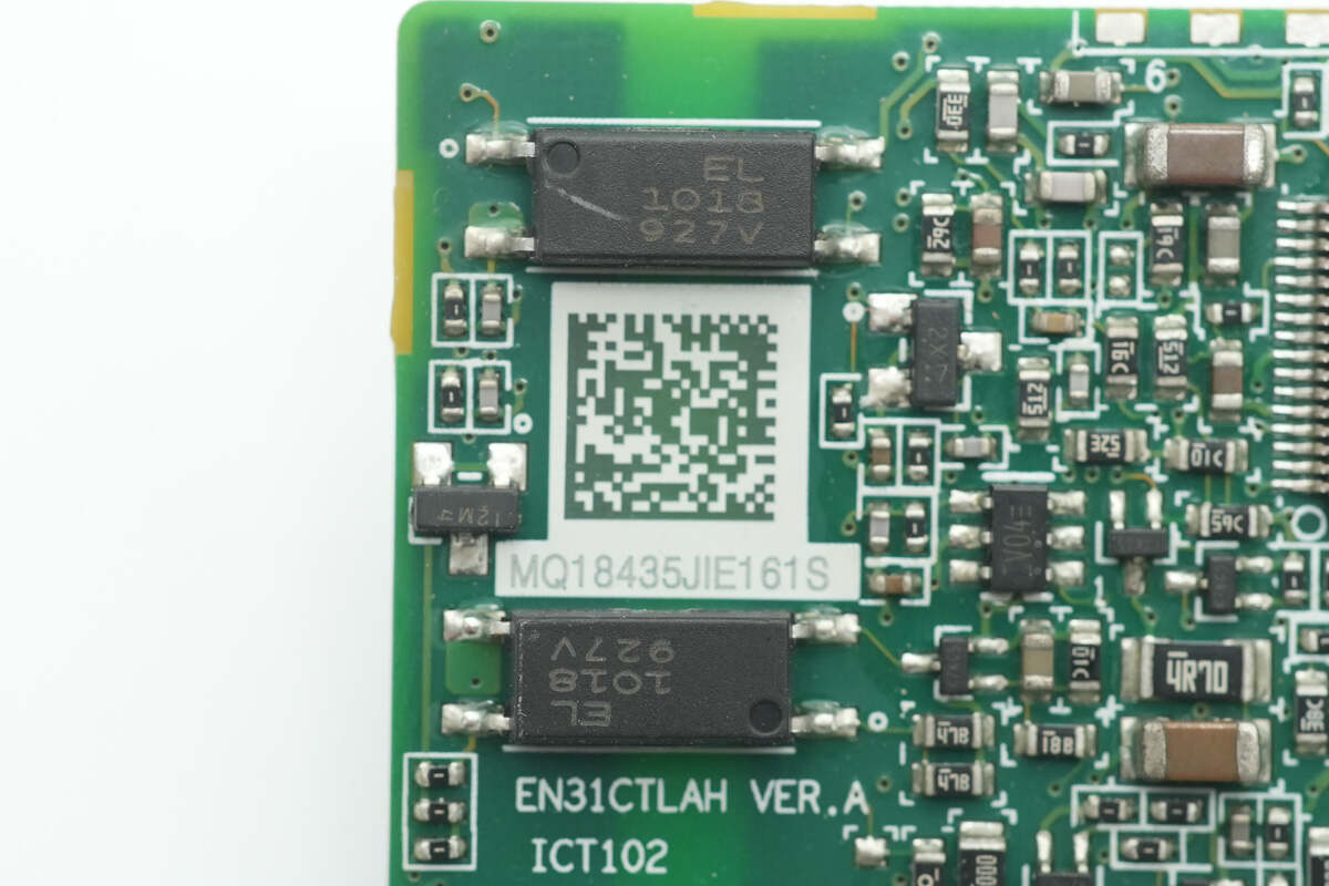
Close-up of the other two optocouplers.
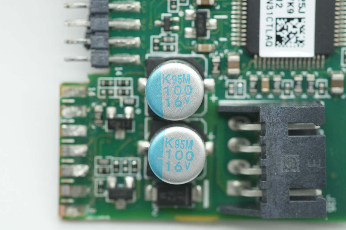
The two filter capacitors have a rating of 100μF 16V.
The inverter is from Nexperia, model 74LVC1G04GV.
There are two LLC modules on the output side.
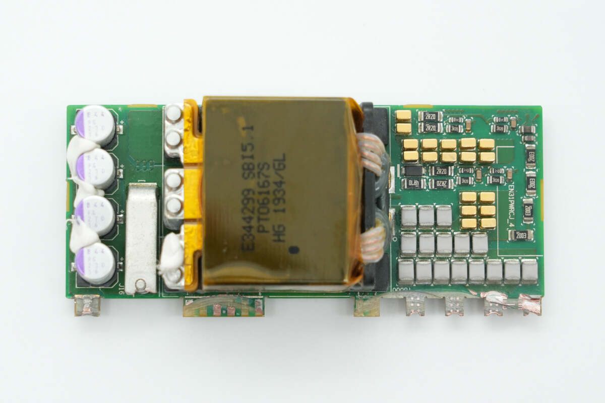
The front side of the LLC module is soldered with resonant capacitors and a transformer, while the right side is soldered with output filter capacitors.
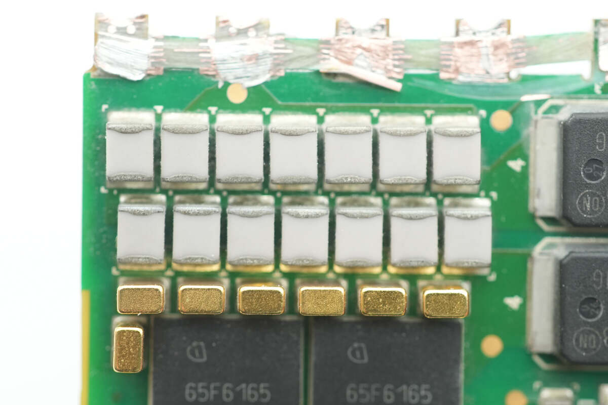
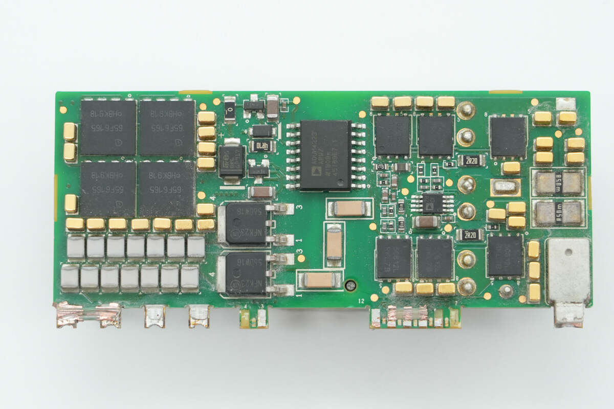
The back side is soldered with LLC MOSFETs, resonant capacitors, diodes, an isolation driver, synchronous rectifiers, and current sense resistors.
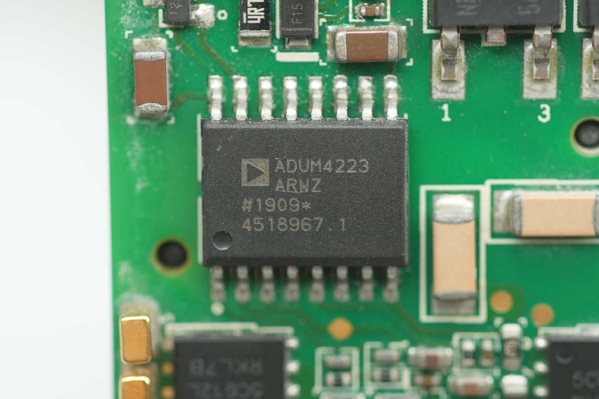
The isolation driver is from ADI, model ADUM4223. It is an isolated precision half-bridge driver with a 4A output current and 5kV RMS isolation capability, packaged in SOIC-1.
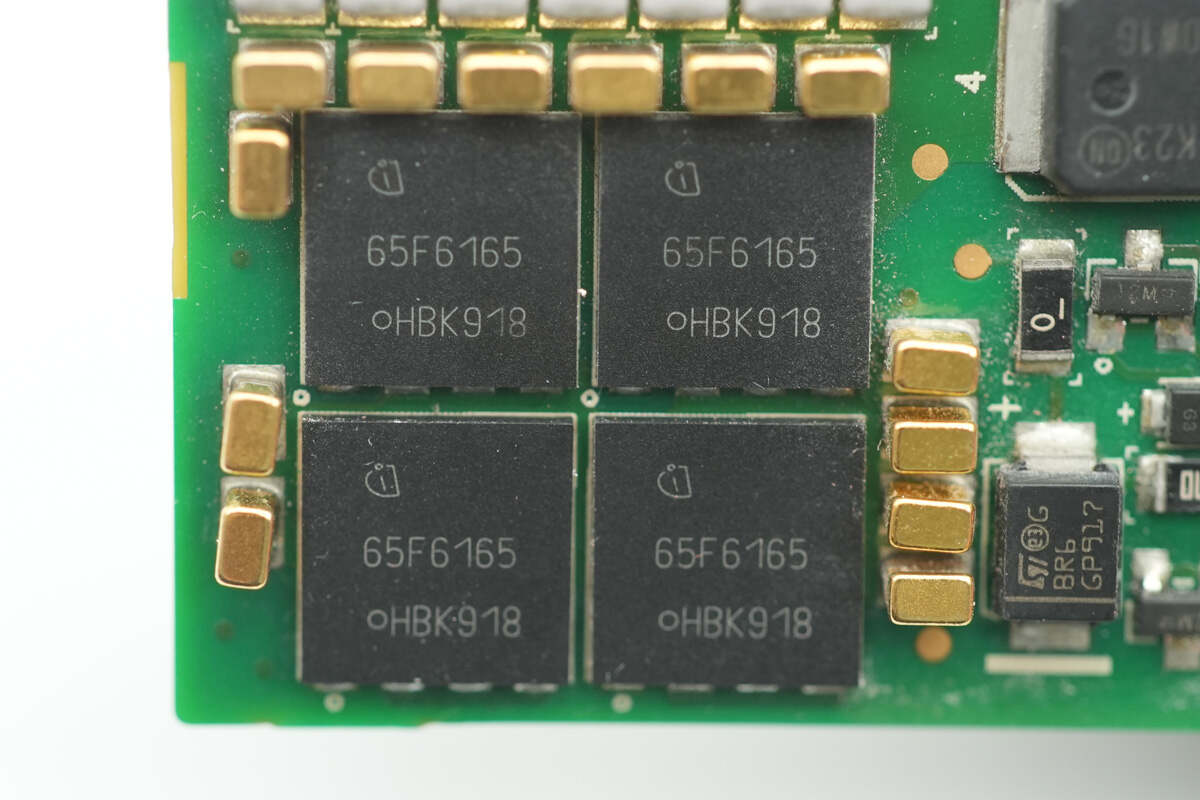
The LLC MOSFETs are from Infineon, marked with 65F6165, model IPL65R165CFD. They are NMOS devices with a voltage rating of 700V, an on-resistance of 165mΩ, and come in VSON-4 packages.
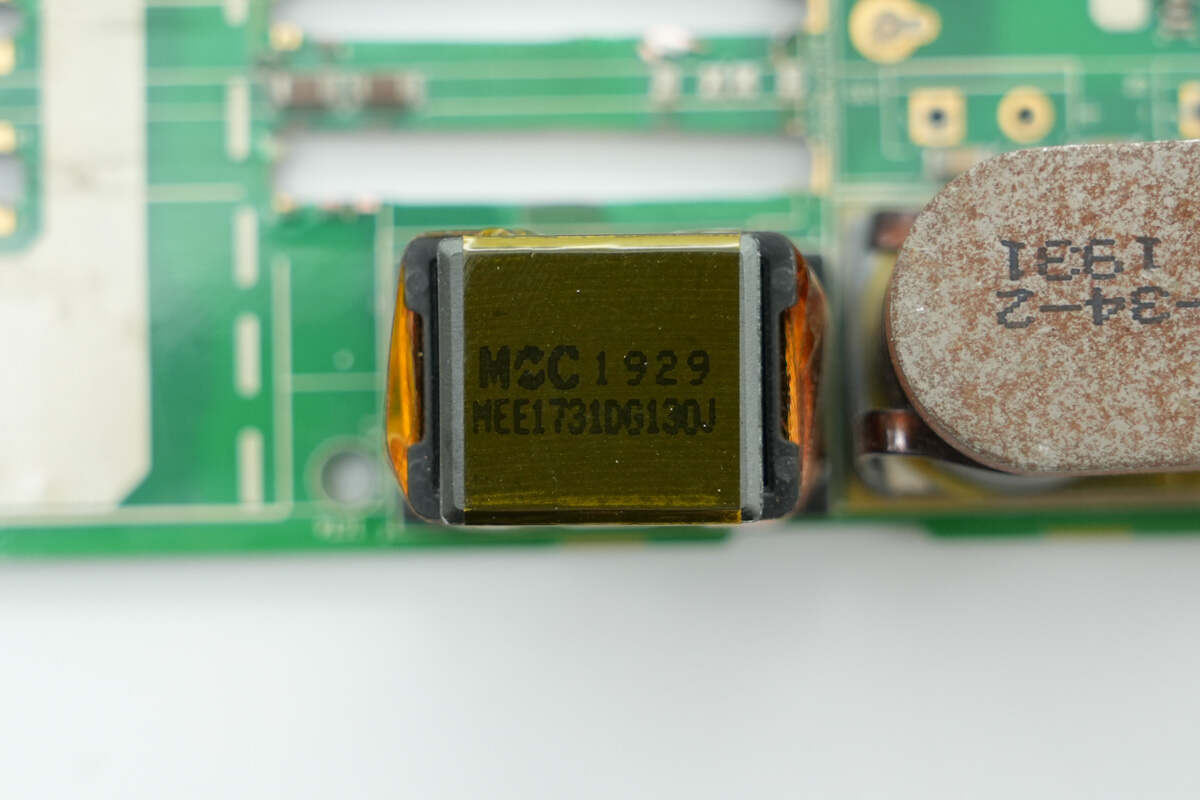
Close-up of a set of NPO resonant capacitors.
There is also a set of NPO resonant capacitors on the other side.
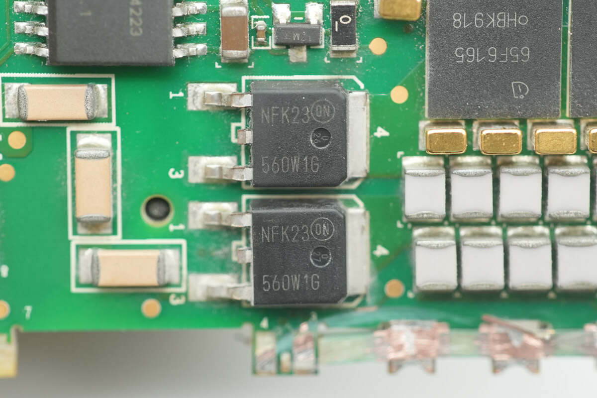
Two series-connected diodes are from Onsemi, model MURHD560W1T4G. They are ultrafast recovery diodes rated at 5A 600V and packaged in DPAK.
The transformer primary winding is made with Litz wire, while the secondary winding is formed by soldered copper strips.
The synchronous rectifier driver uses the ADI ADP3654.
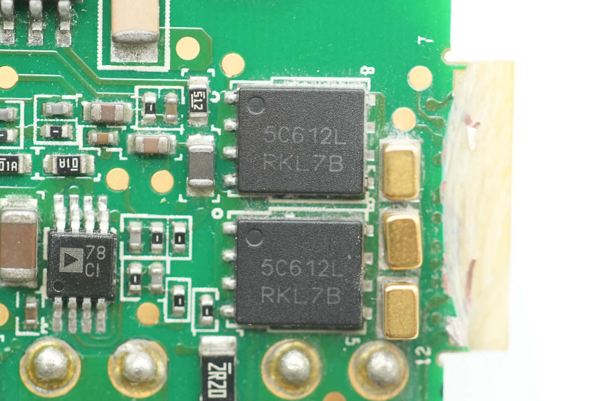
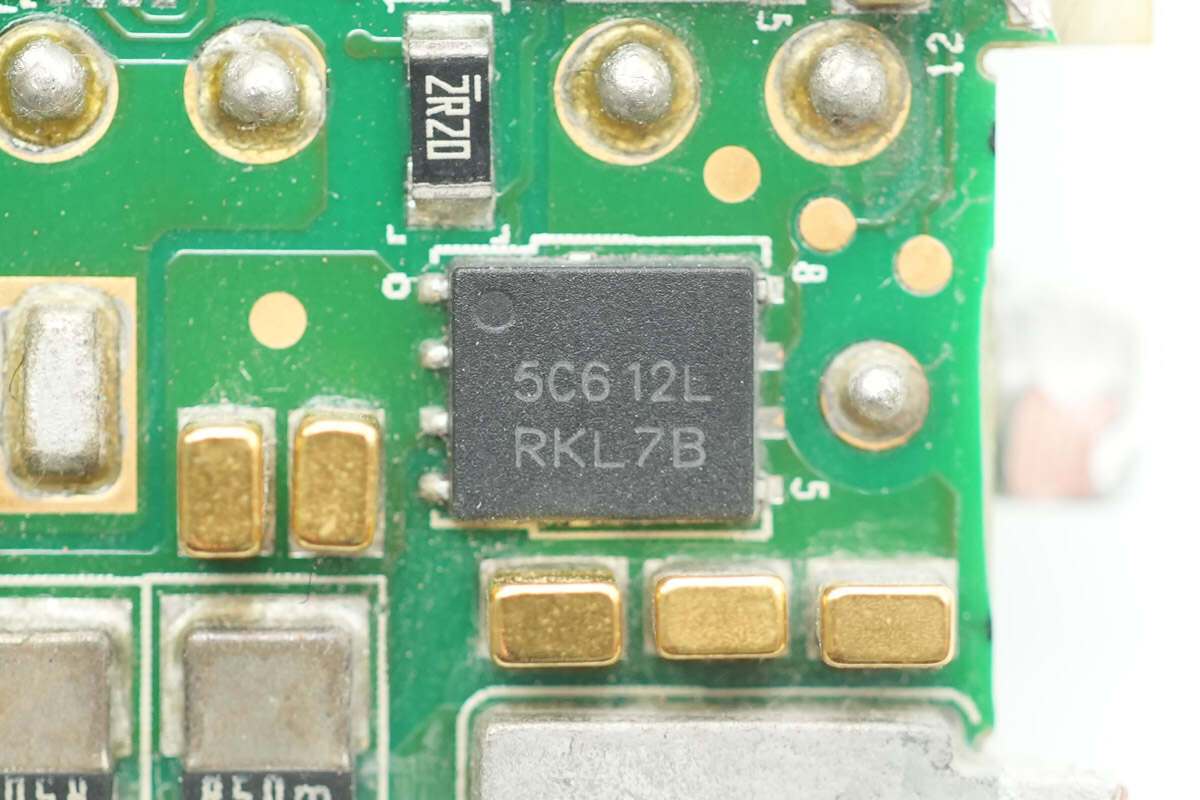
The synchronous rectifiers are from Onsemi, model NTMFS5C612NL. These are NMOS devices rated at 60V with an on-resistance of 1.5mΩ, and come in DFN5 packages.
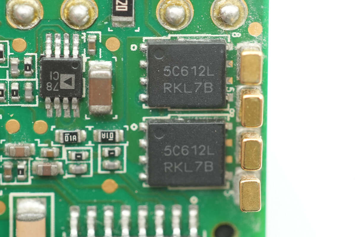
The other two synchronous rectifiers are of the same model.
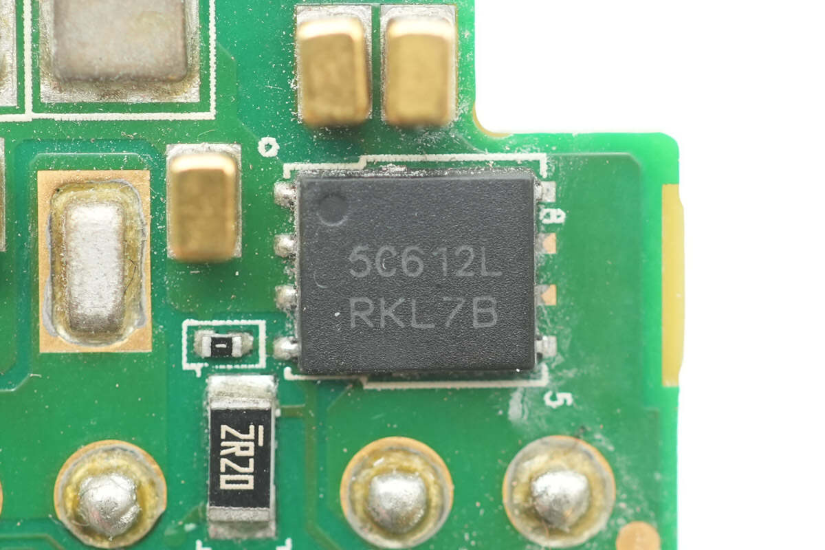
In addition, there are two more synchronous rectifiers of the same model.
The rectifiers are grouped in sets of three for LLC synchronous rectification, helping to distribute heat evenly and reduce temperature rise.
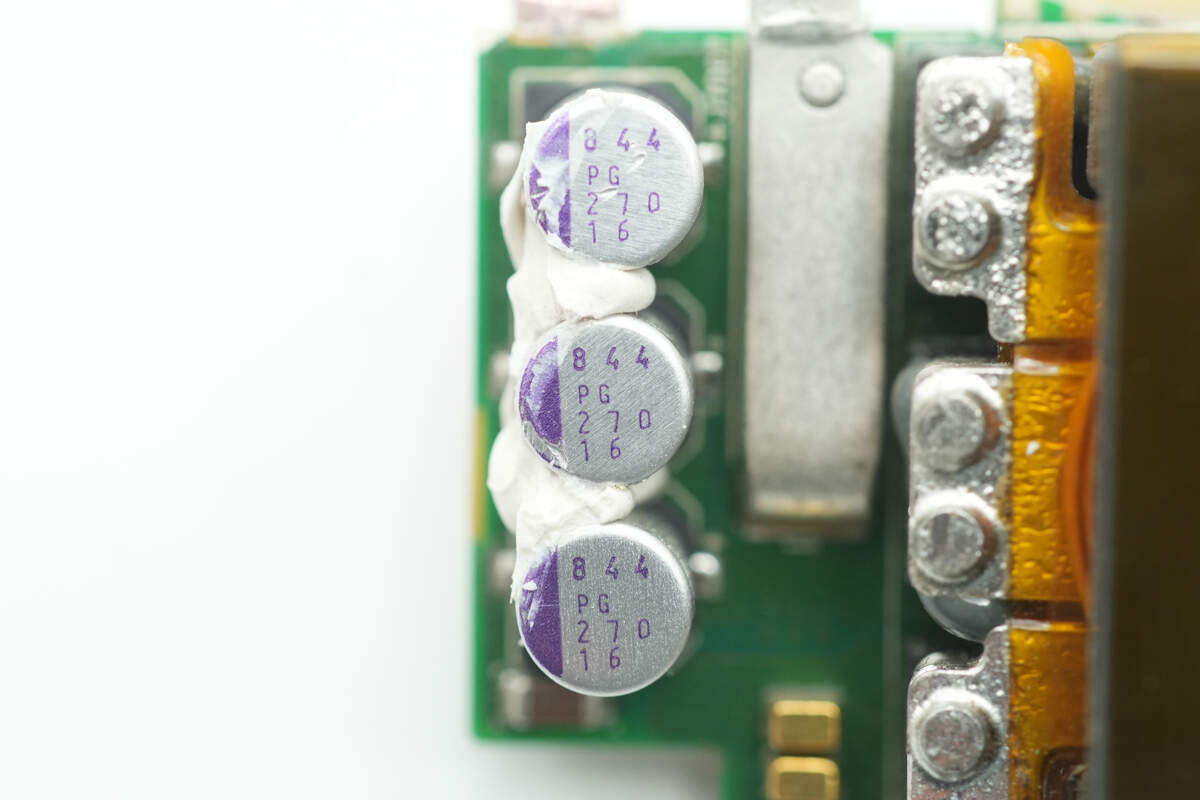
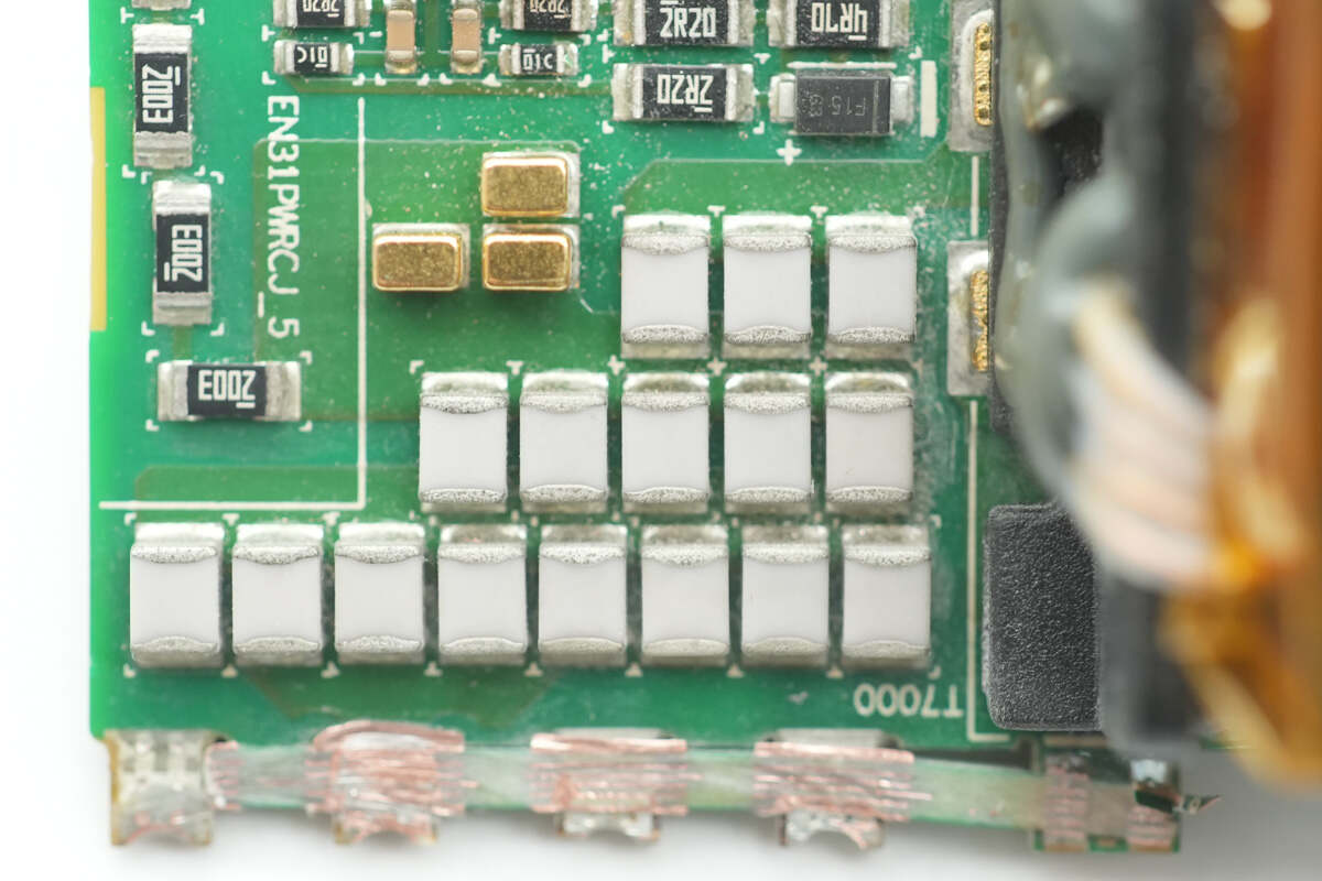
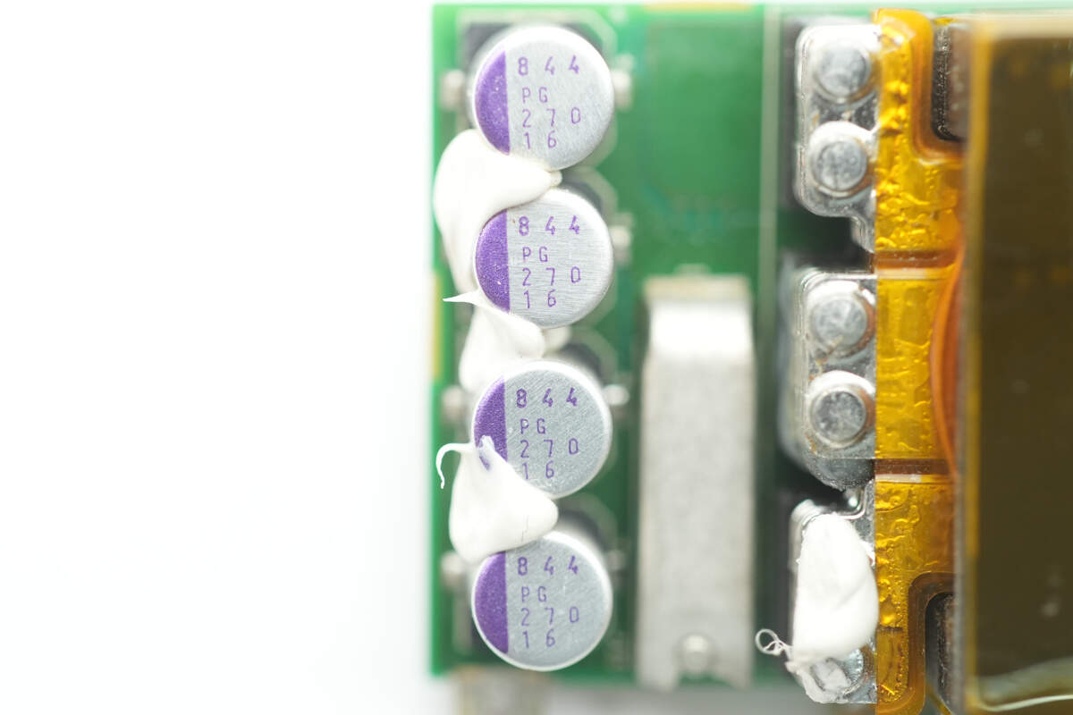
The output filter capacitors are from Panasonic, part of the SVPG series of conductive polymer solid capacitors. They are rated at 270μF 16V, with three connected in parallel.
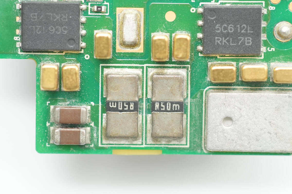
Two 0.5mΩ resistors are connected in parallel to sense the output current.
The other LLC PCB is symmetrically designed to the previous one, with only the four output filter capacitors being different.
The backside layout is identical, so it will not be described further to save space.
The filter capacitors are rated at 270μF 16V.
The LLC resonant inductor is wound with Litz wire.
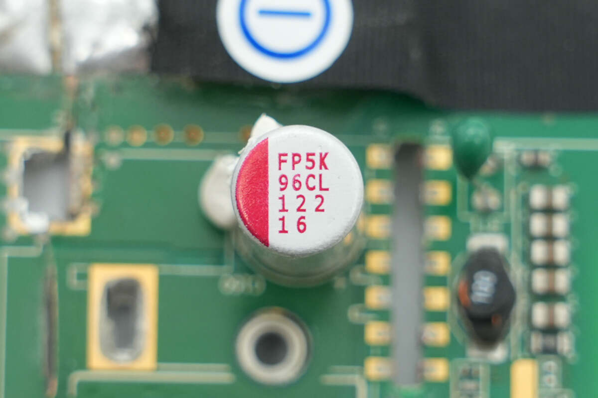
This output filter capacitor is rated at 1200μF 16V.
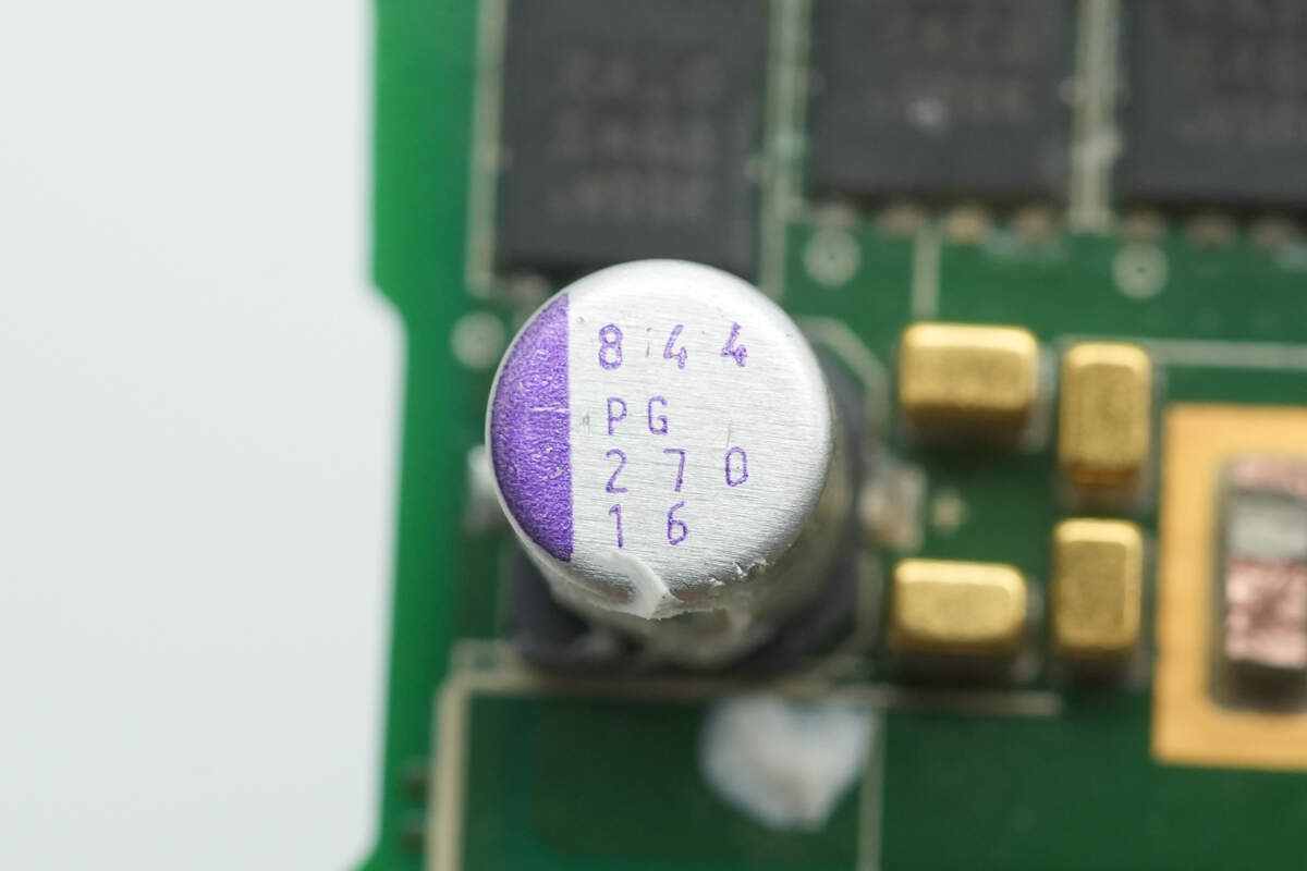
The other output filter capacitor is rated at 270μF 16V.
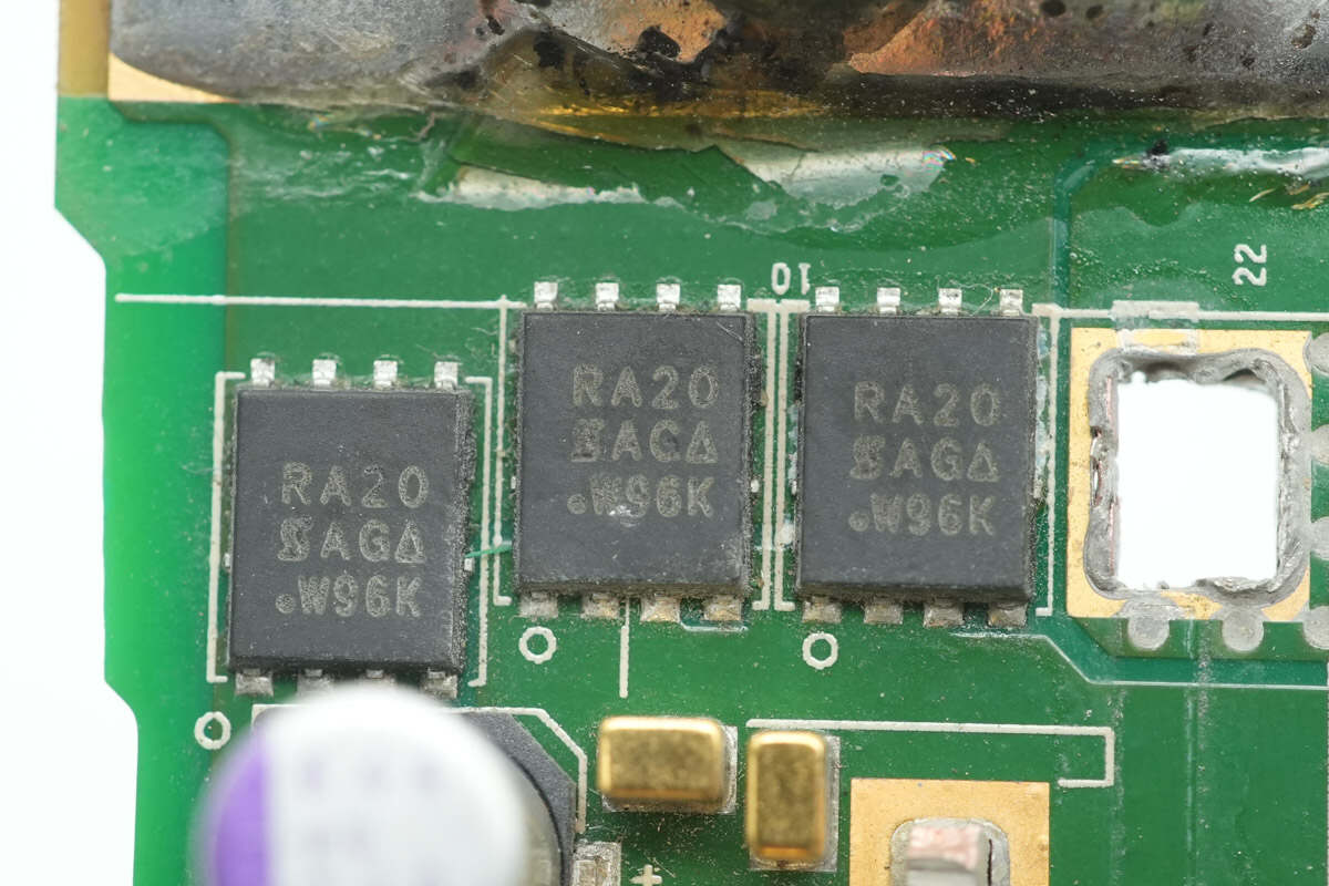
The output VBUS MOSFET is from VISHAY, model SiRA20DP. It is an NMOS device rated at 25V with an on-resistance of 0.48mΩ, packaged in PowerPAK SO-8.
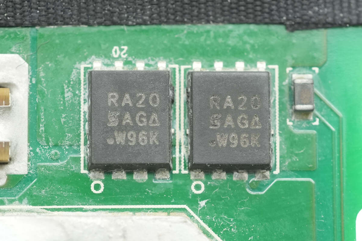
The backside also has two VBUS MOSFETs of the same model.

The dual op-amp is from ADI, model AD823. It is a high-precision dual-channel op-amp with rail-to-rail JFET inputs, supports single-supply operation, and comes in an SOIC-8 package.
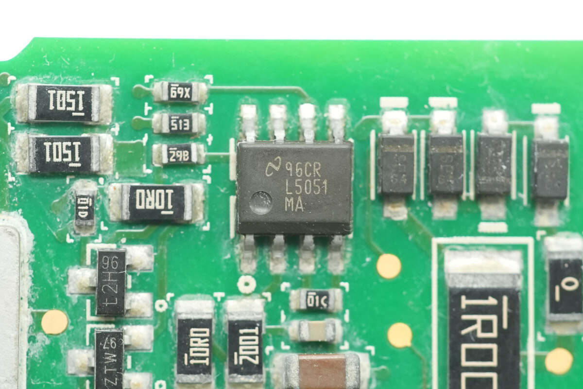
The ideal diode controller is from TI, model LM5051. It is designed for low-side applications, supports input voltages down to 100V, features a built-in NMOS driver, offers a fast reverse response time of 50ns, and is packaged in an SOIC-8 case.
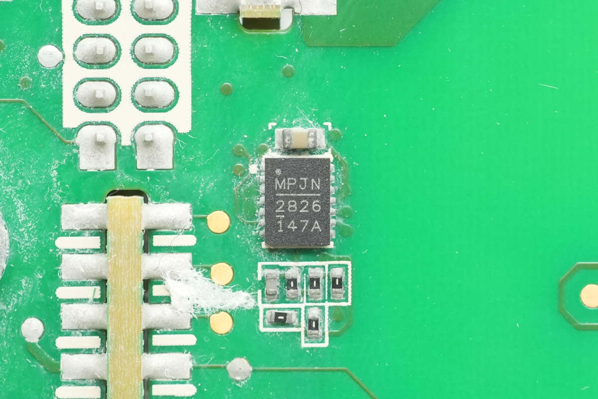
The MPQ28261 synchronous buck converter is used to supply power to the control PCB.
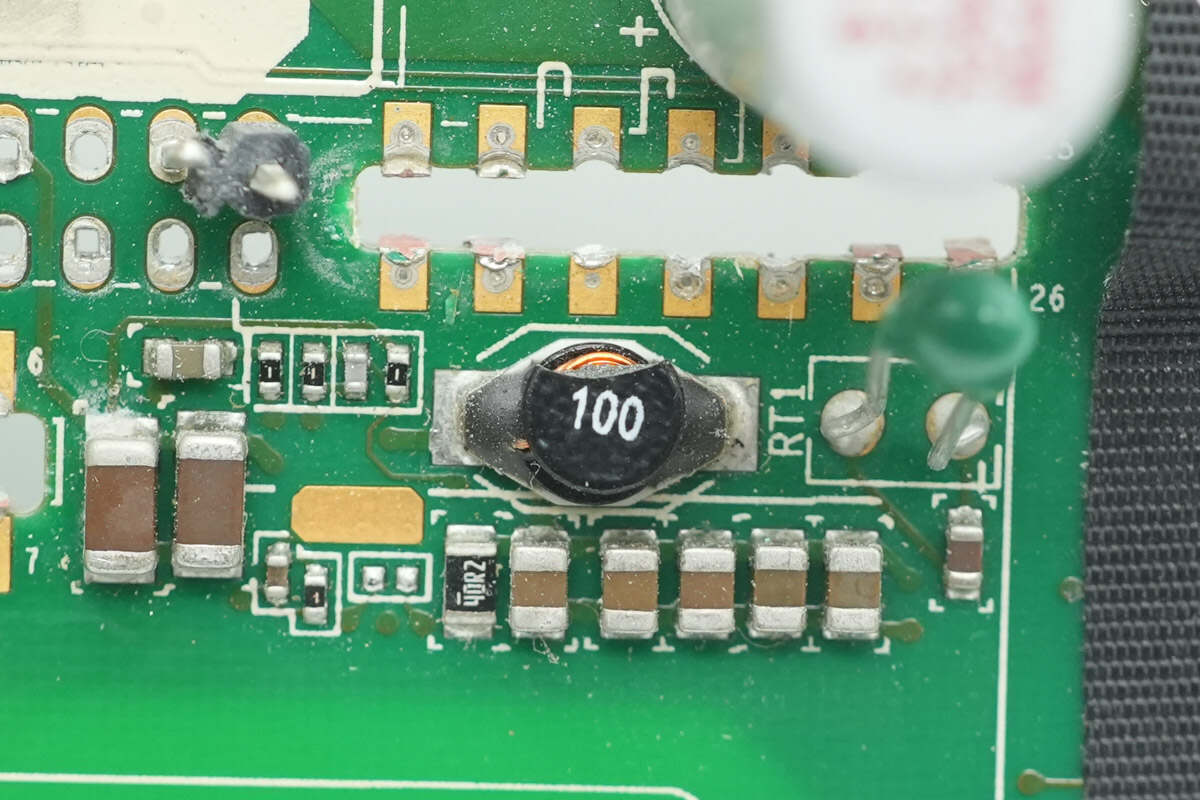
Close-up of the 10μH buck inductor.
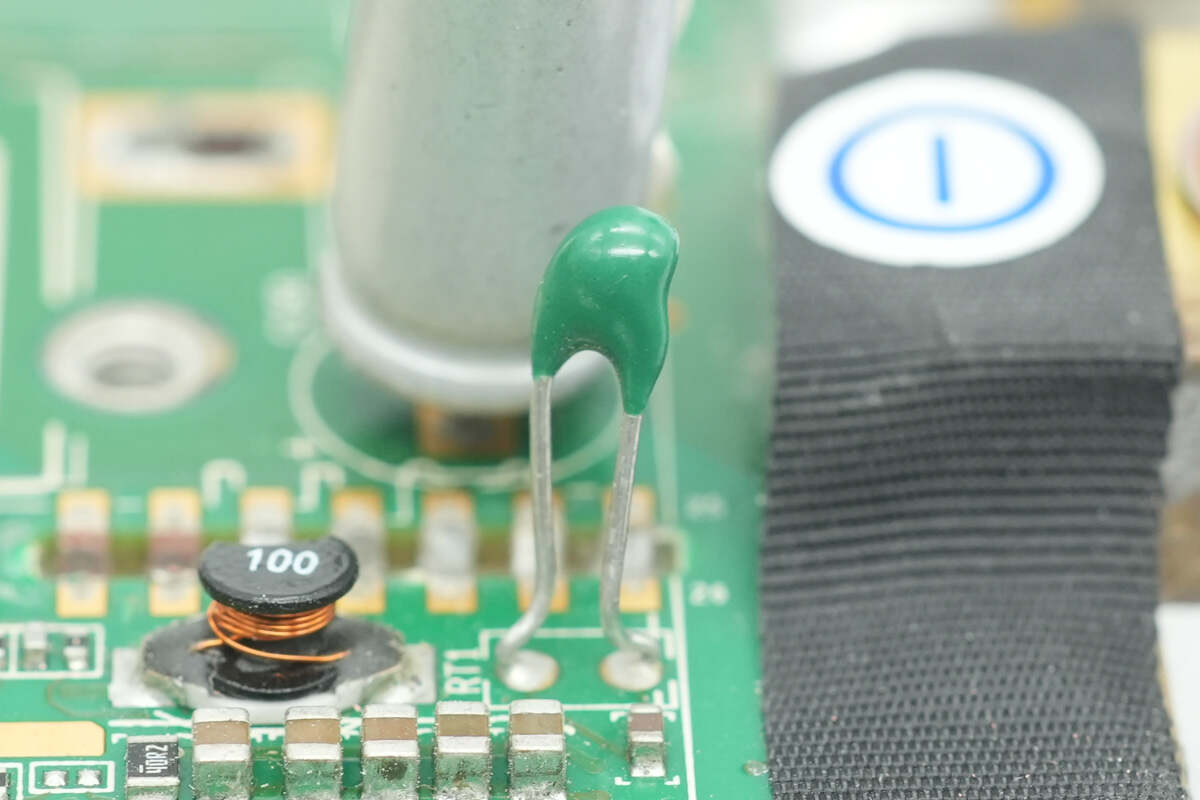
The thermistor is used to monitor the temperature at the power supply air inlet.
Well, those are all components of the xFusion’s FusionWatt 2000W Platinum Server Power Supply.
Summary of ChargerLAB
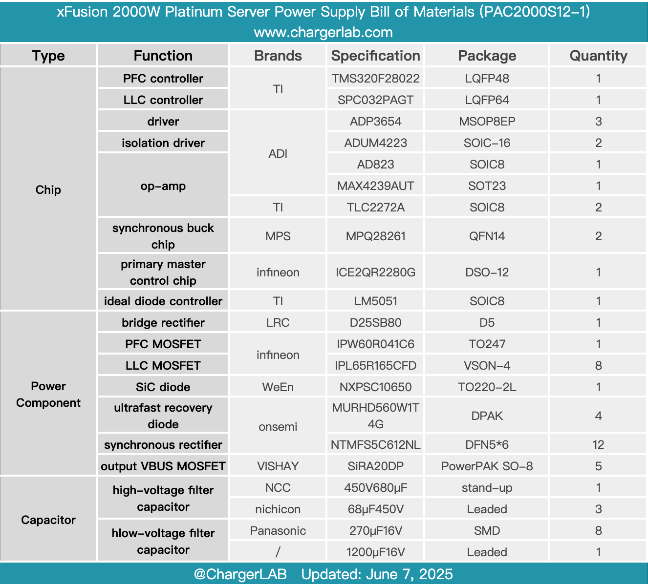
Here is the component list of the xFusion’s FusionWatt 2000W Platinum Server Power Supply for your convenience.
Model PAC2000S12-1, supporting a wide input voltage range with a rated output power of 2000W. It features an internal cooling fan that draws air in from the output side and exhausts it through the input side for heat dissipation.
After taking it apart, we found that it uses a PFC+LLC architecture. The PFC controller is a TI TMS320F28022 paired with an ADI ADP3654 driver, utilizing Infineon IPW60R041C6 MOSFETs and RePower NXPSC10650 SiC diodes.
The LLC controller uses the SPC032PAGT. The power stage features a symmetrical dual-channel design, with primary MOSFETs being Infineon IPL65R165CFD devices, driven by ADI ADUM4223. The synchronous rectifiers are Onsemi NTMFS5C612NL. The auxiliary power supply uses the Infineon ICE2QR2280. All internal capacitors are Japanese-brand, and the output is filtered with solid capacitors, reflecting solid and reliable workmanship and material quality.
Related Articles:
1. Teardown of CUKTECH 10 GaN Charger Ultra (AD1204U)
2. Teardown of Lenovo thinkplus FLUXO 140W 20000mAh Power Bank (SLPB-20140)
3. Teardown of DJI 2600W 1024Wh Power 1000 V2 Portable Power Station