Introduction
This teardown features a VMAX server power supply, model VT450AB220A. The power supply supports a 100–240V AC input and delivers a 12V output at 37A, along with a secondary 5V output at 3A. Internally, the power supply employs a PFC + LLC + synchronous rectification architecture and includes built-in fast-recovery diodes. Let’s take a look at its internal design and components.
Product Appearance
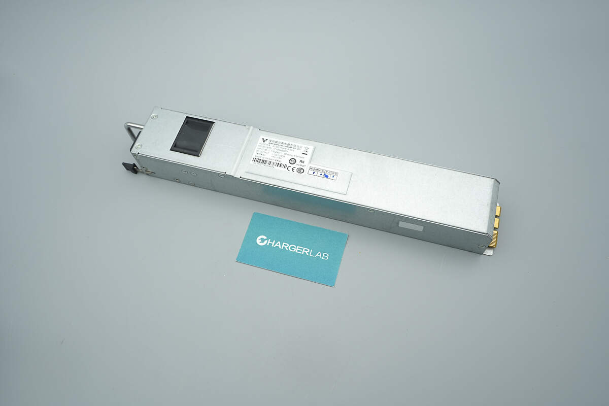
The enclosure is made of galvanized steel and has a label affixed to the front.
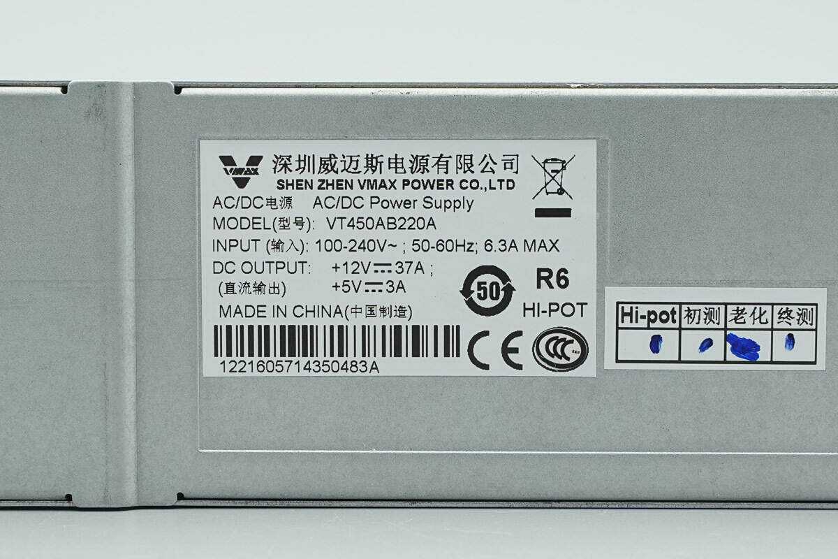
Model: VT450AB220A
Input: 100–240V~; 50–60Hz; 6.3A MAX
DC Output: +12V⎓37A;
+5V⎓3A
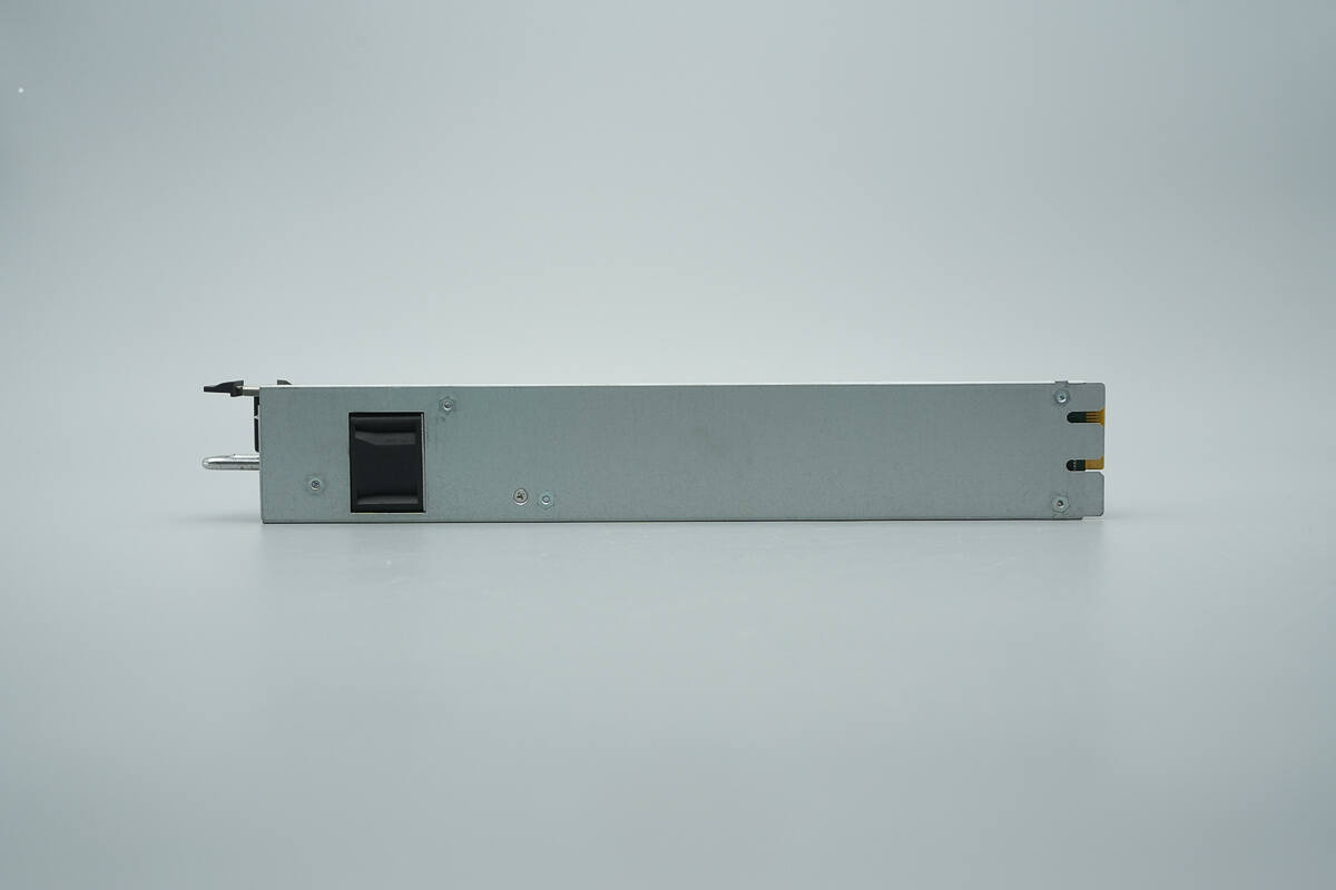
The area corresponding to the cooling fan is perforated to reduce thickness.
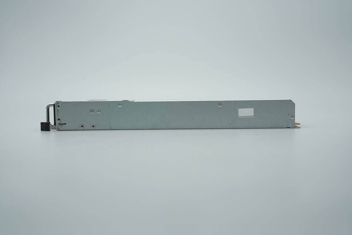
The sides are secured with screws.
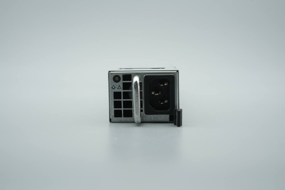
The input end features an indicator light, a carrying handle, a three-prong power socket, and a release latch.
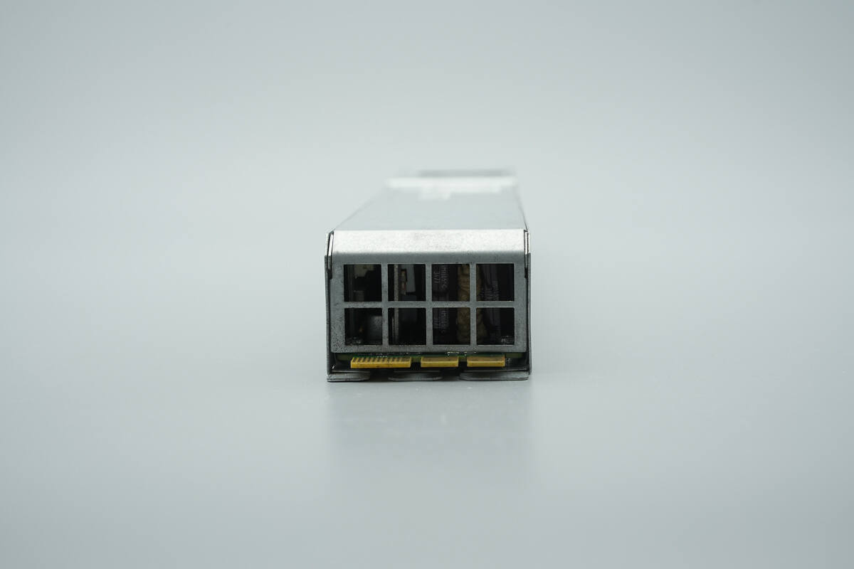
The output end is equipped with a cooling grille and a gold finger connector.
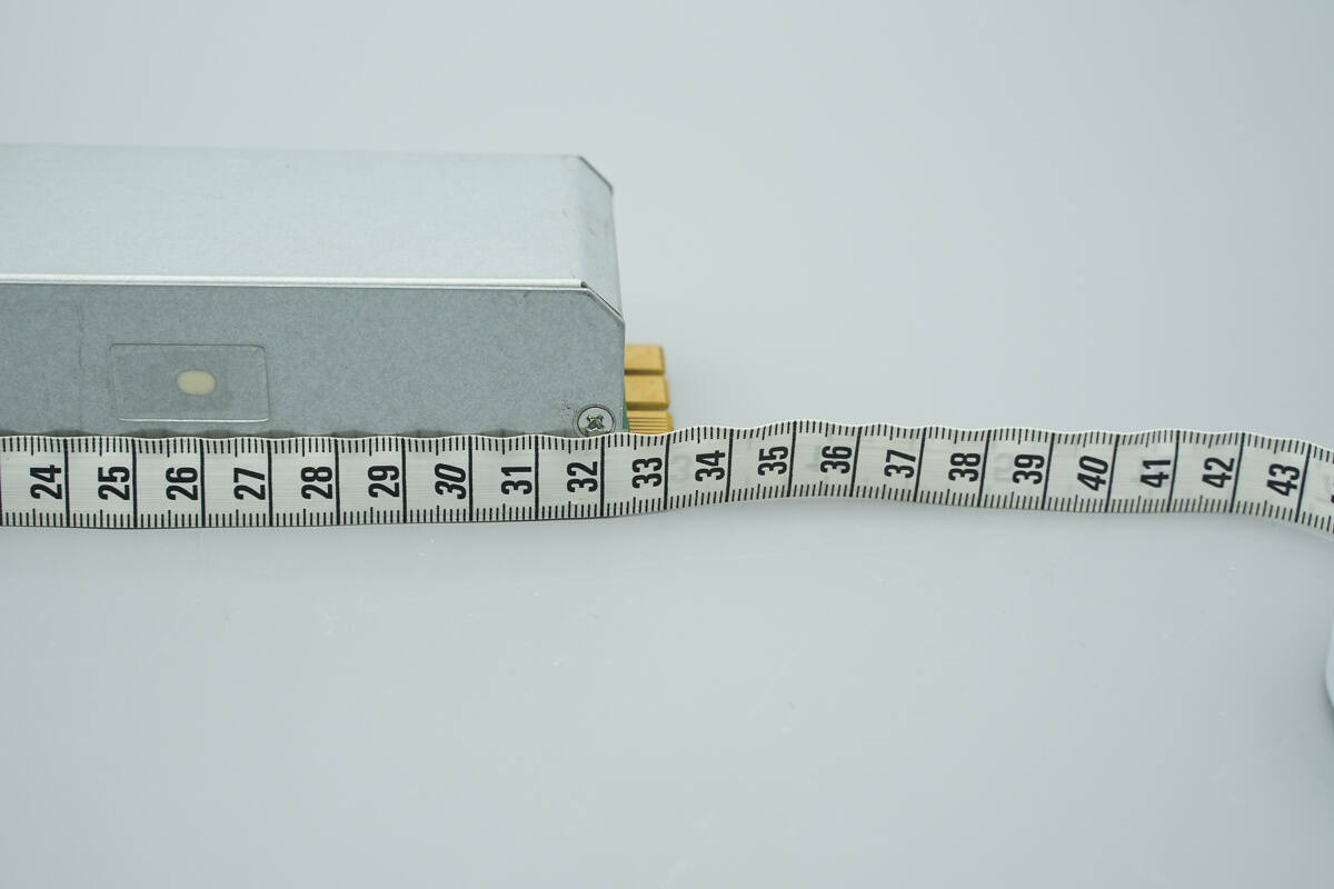
The length of the module is about 330 mm (12.99 inches).
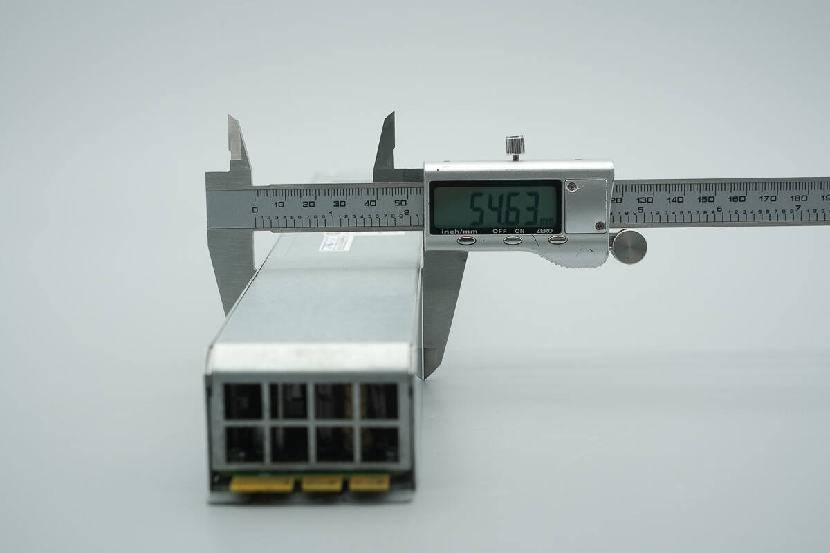
The width is about 54.6 mm (2.15 inches).
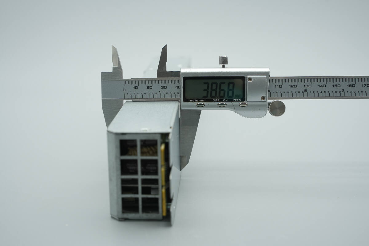
The thickness is about 38.7 mm (1.52 inches).
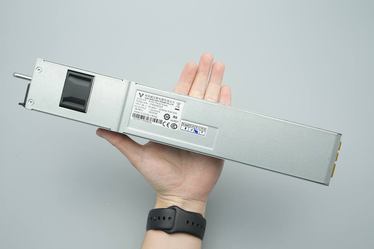
That's how big it is in the hand.
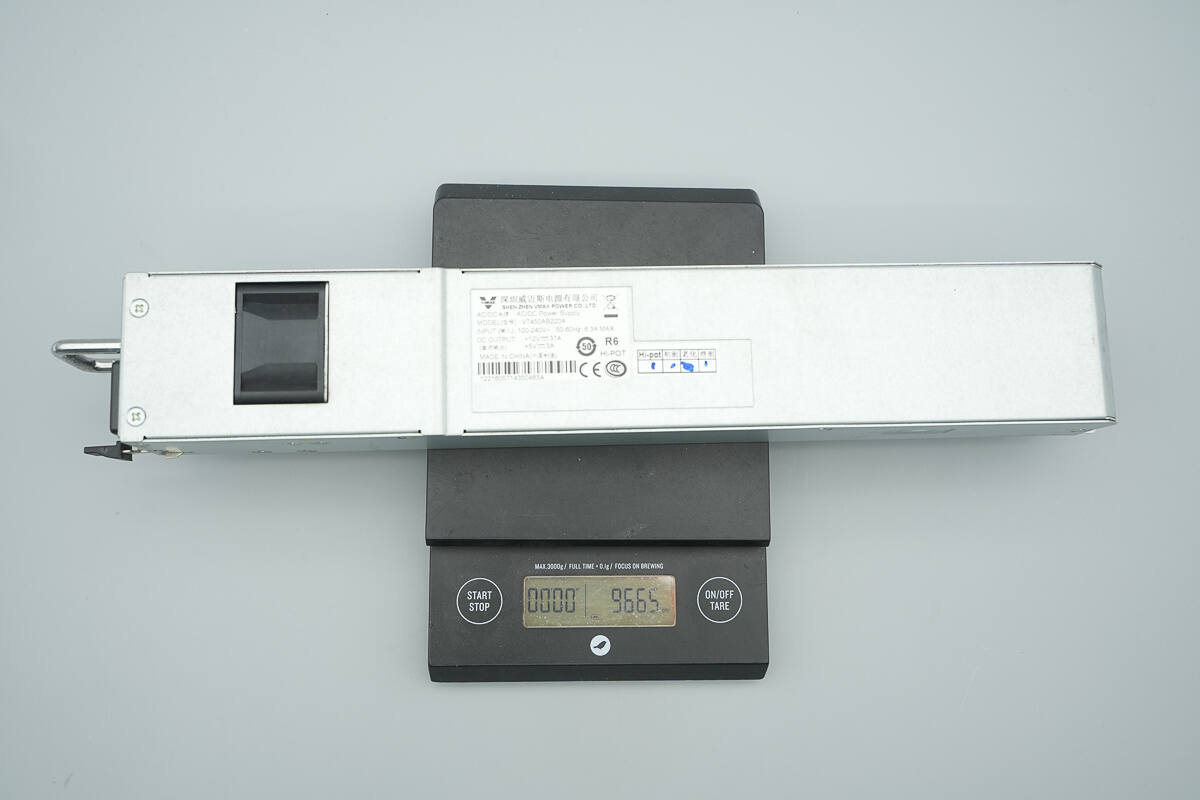
The weight is about 967 g (34.11 oz).
Teardown
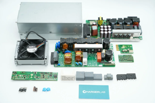
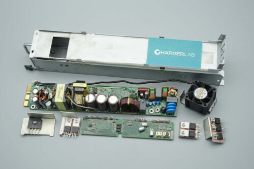
Next, let's take it apart to see its internal components and structure.
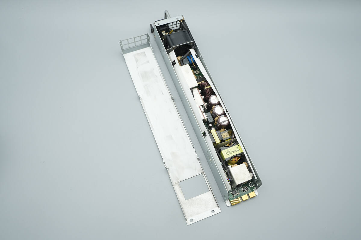
Unscrew the screws to open the power supply enclosure.
The PCBA module is wrapped with Mylar insulation sheets.
The PCBA module is secured with screws.
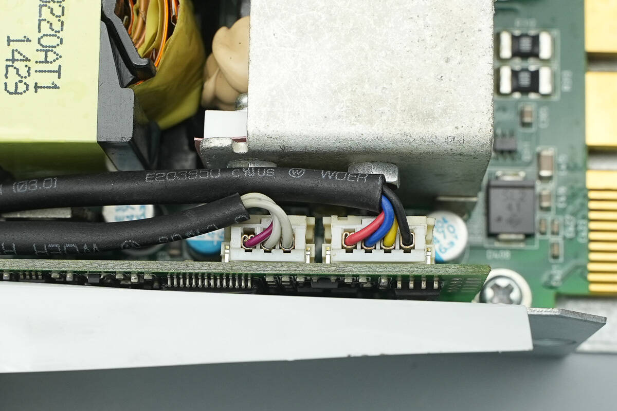
The indicator light and cooling fan are connected via connectors, and the wires are insulated with heat-shrink tubing.
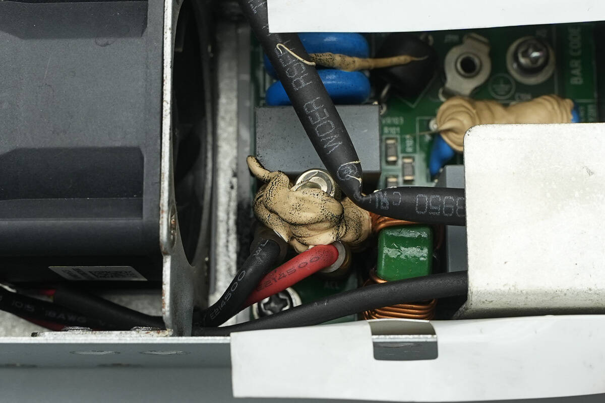
The power input wires are connected by soldering and reinforced with adhesive.
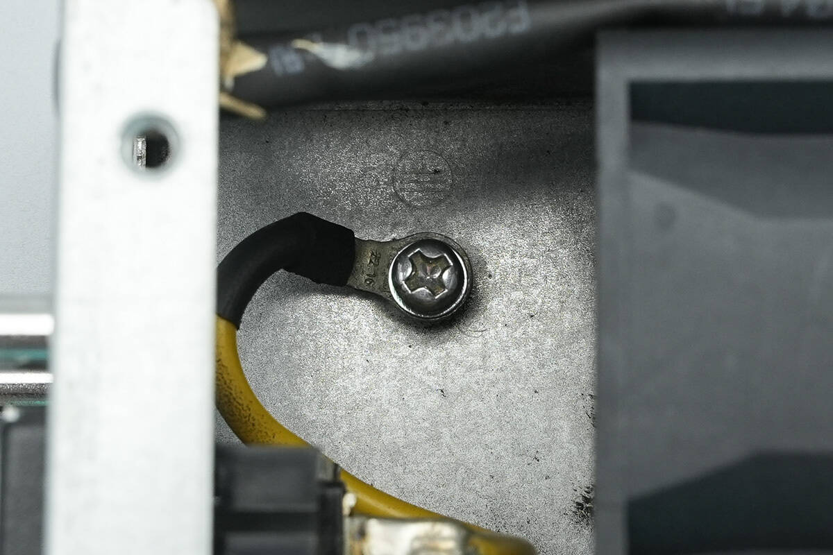
The grounding wire is secured to the enclosure with a screw.
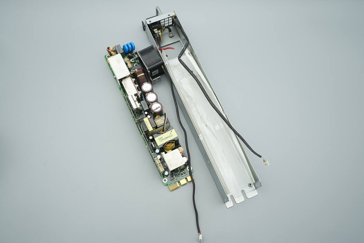
Remove the PCBA module.
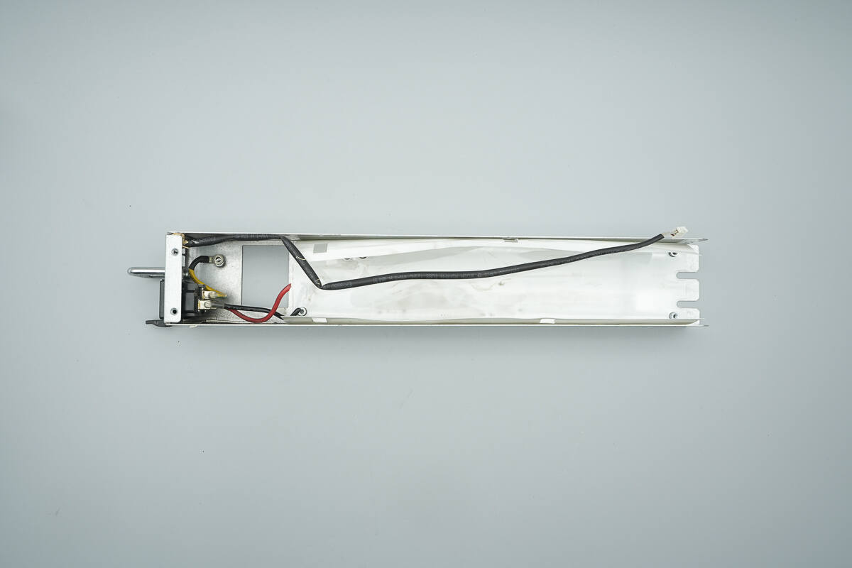
The enclosure interior is insulated with a white Mylar sheet.
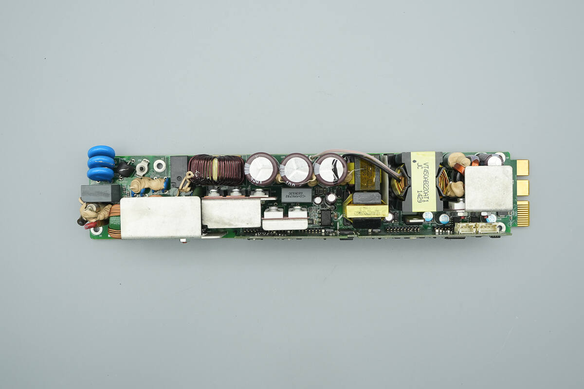
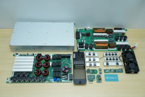
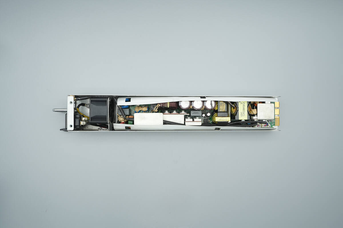
The front side of the PCBA module features components including a fuse, common mode choke, safety X2 capacitor, varistors, gas discharge MOSFET, bridge rectifier, relay, NTC thermistor, PFC boost inductor, PFC MOSFETs, and PFC rectifier.
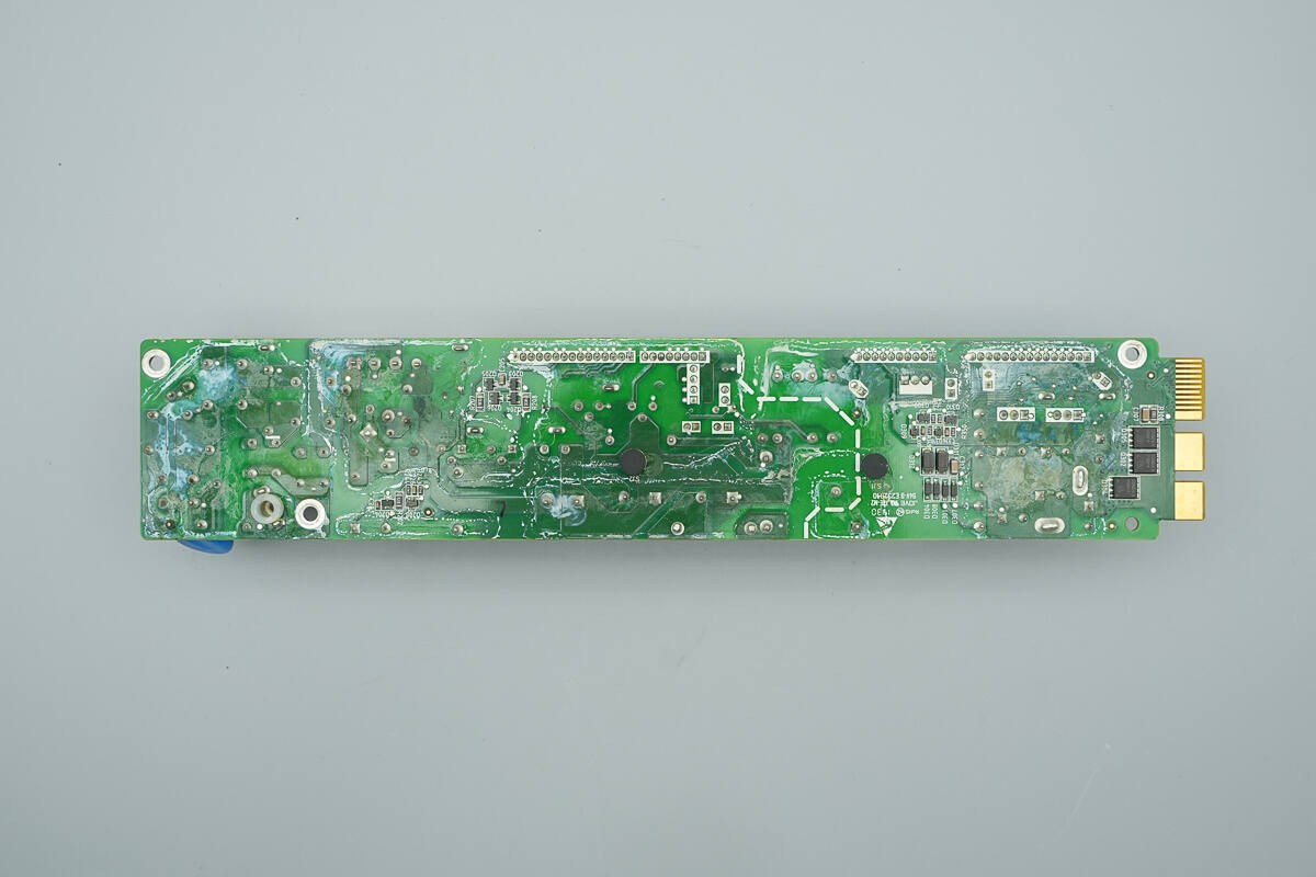
The back side of the PCBA module is equipped with output control MOSFETs.
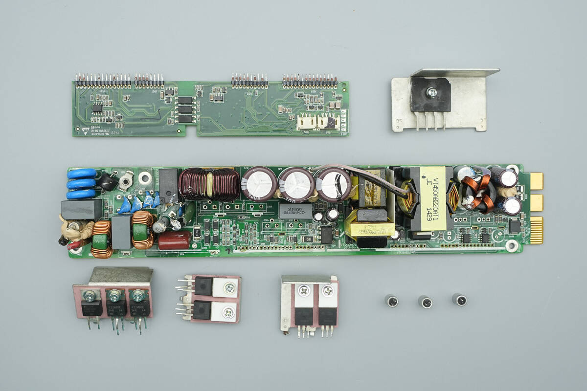
Remove the heatsinks from the bridge rectifier, PFC MOSFETs, LLC MOSFETs, and synchronous rectifiers, then detach the control PCB.
The fuse at the input end is insulated with heat-shrink tubing.
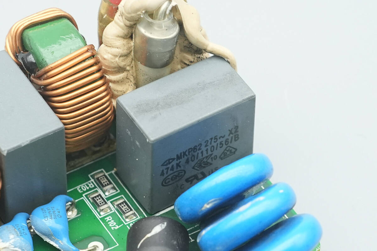
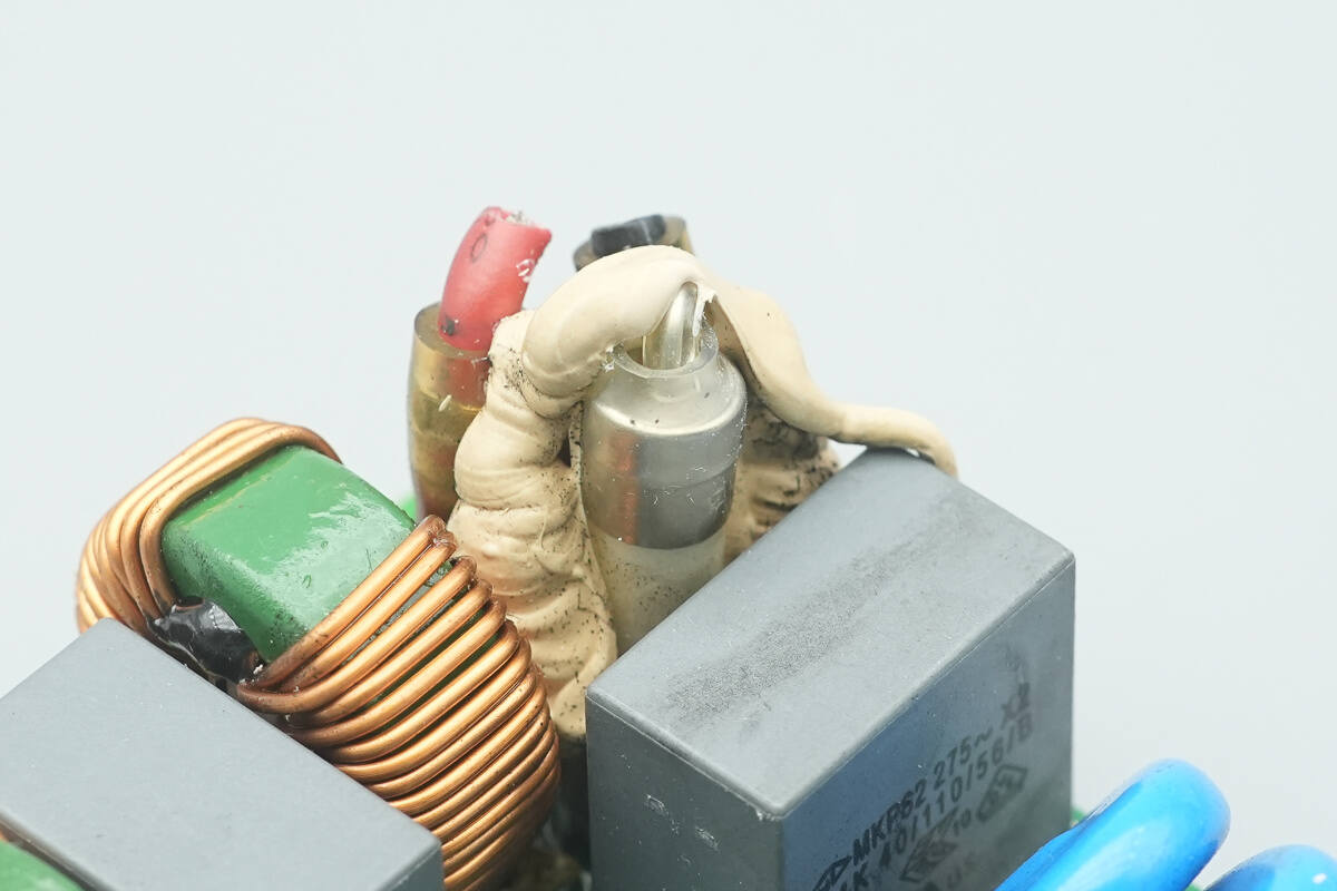
The safety X2 capacitor is from Faratronic, with a specification of 0.47 μF.
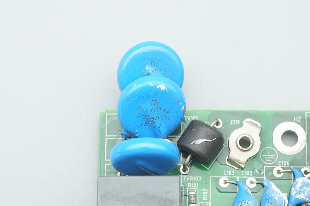
The varistors are from BrightKing, part number 561KD14J, used for absorbing overvoltage surges.
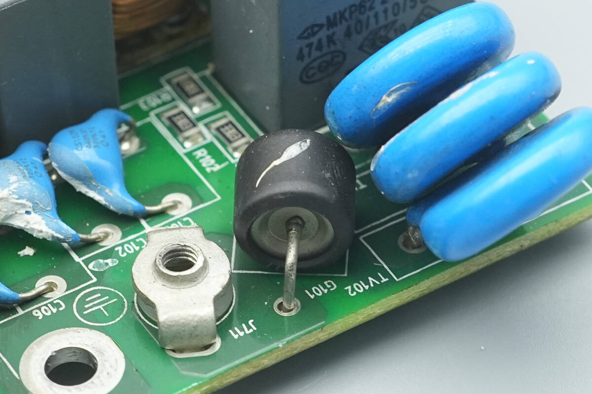
The gas discharge MOSFET is insulated with heat-shrink tubing.
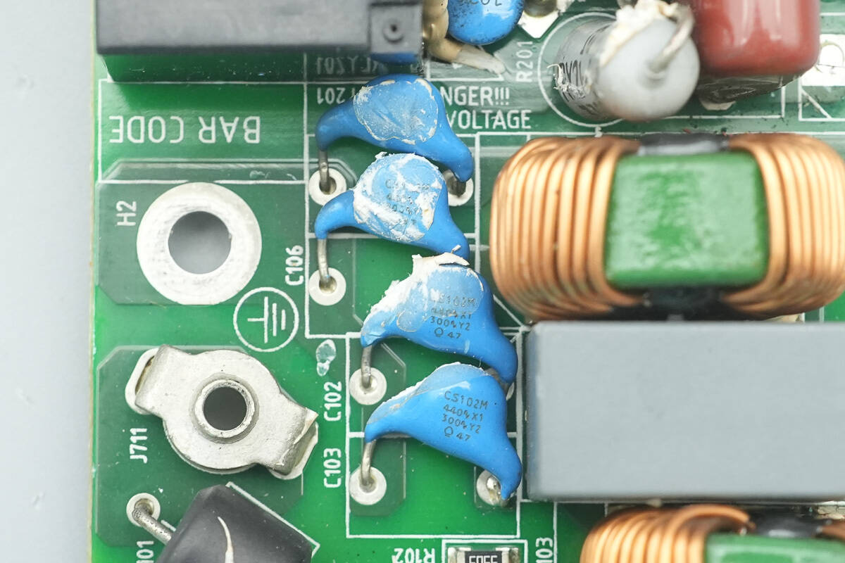
The blue Y-capacitors have the part number CS102M.
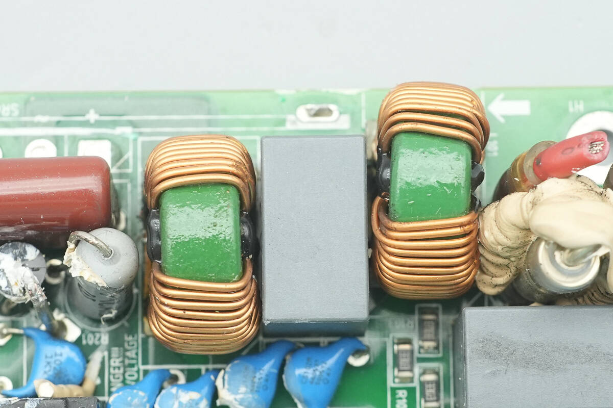
The common mode choke is wound with enameled wire.
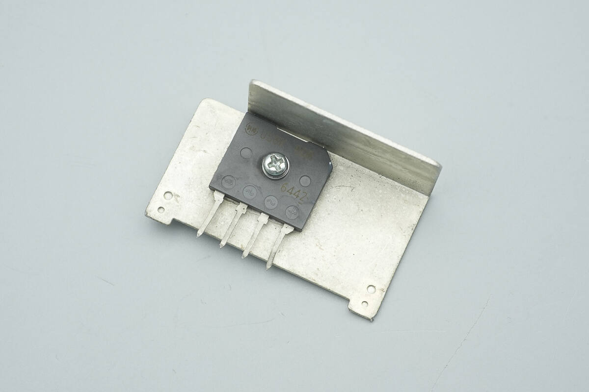
The bridge rectifier is secured to the heatsink with a screw.
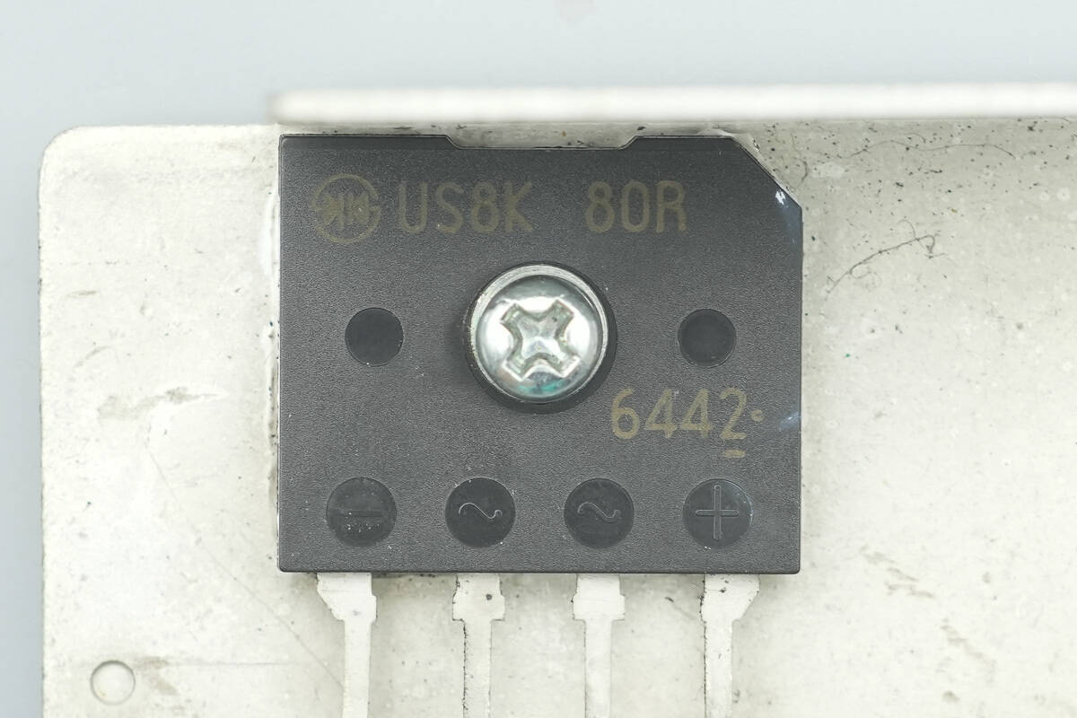
The bridge rectifier is from Shindengen, model US8K80R, rated at 800 V, 8 A, and uses a D6K package.
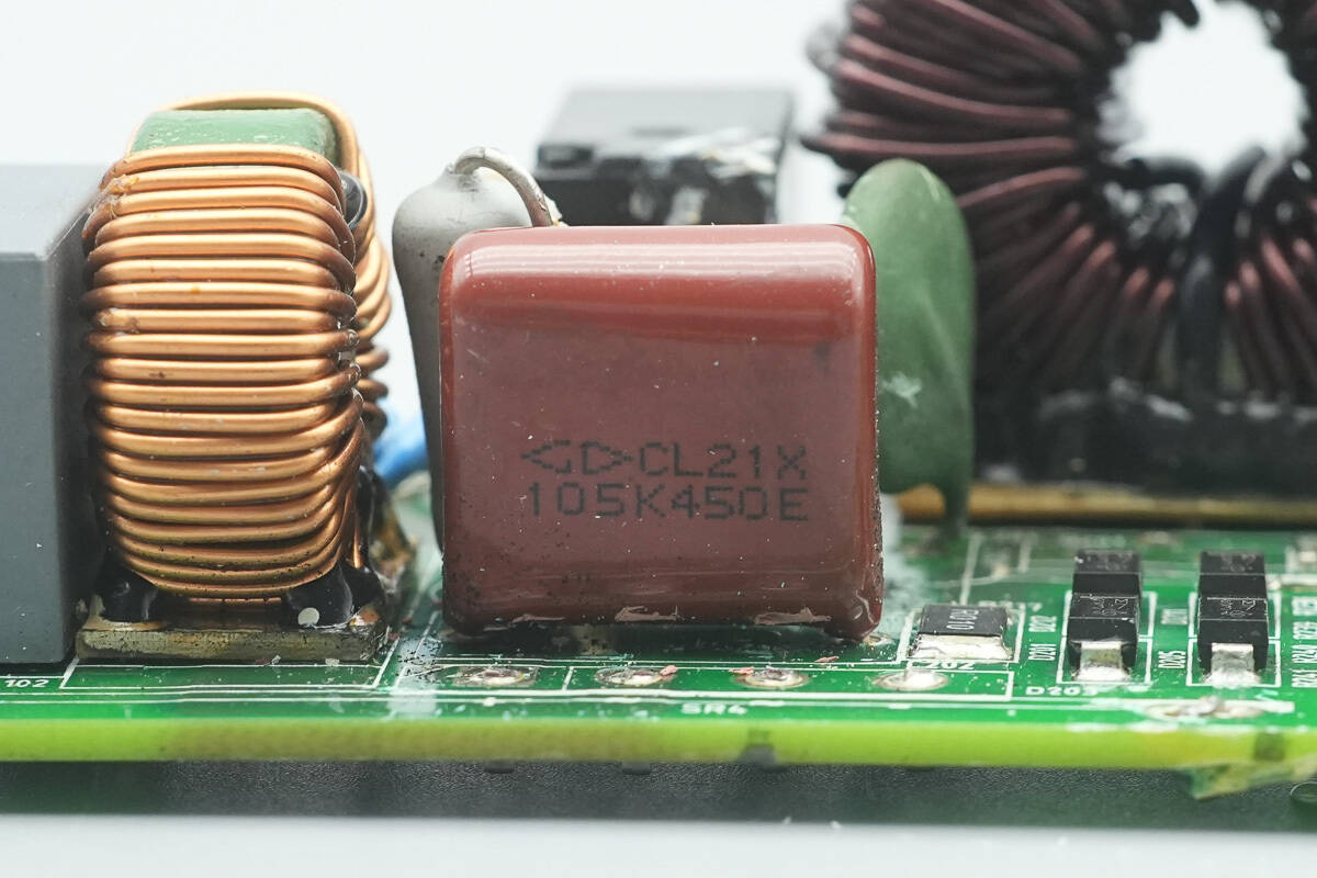
The film capacitor is rated at 1 μF, 450 V.
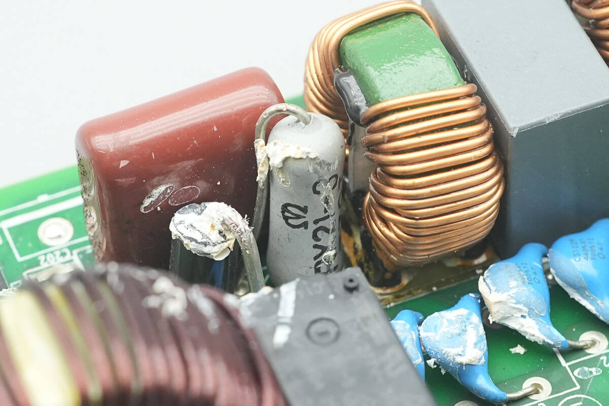
The current-limiting resistor is connected in series with a bypass diode.
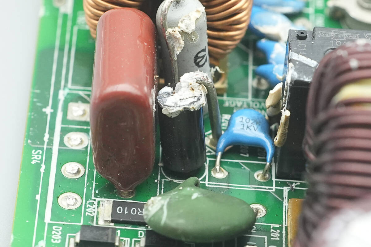
Close-up of the bypass diode.
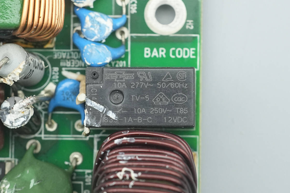
The relay is from SongChuan, model 835-1A-B-C, with a contact rating of 10 A at 250 V and a coil voltage of 12 V.
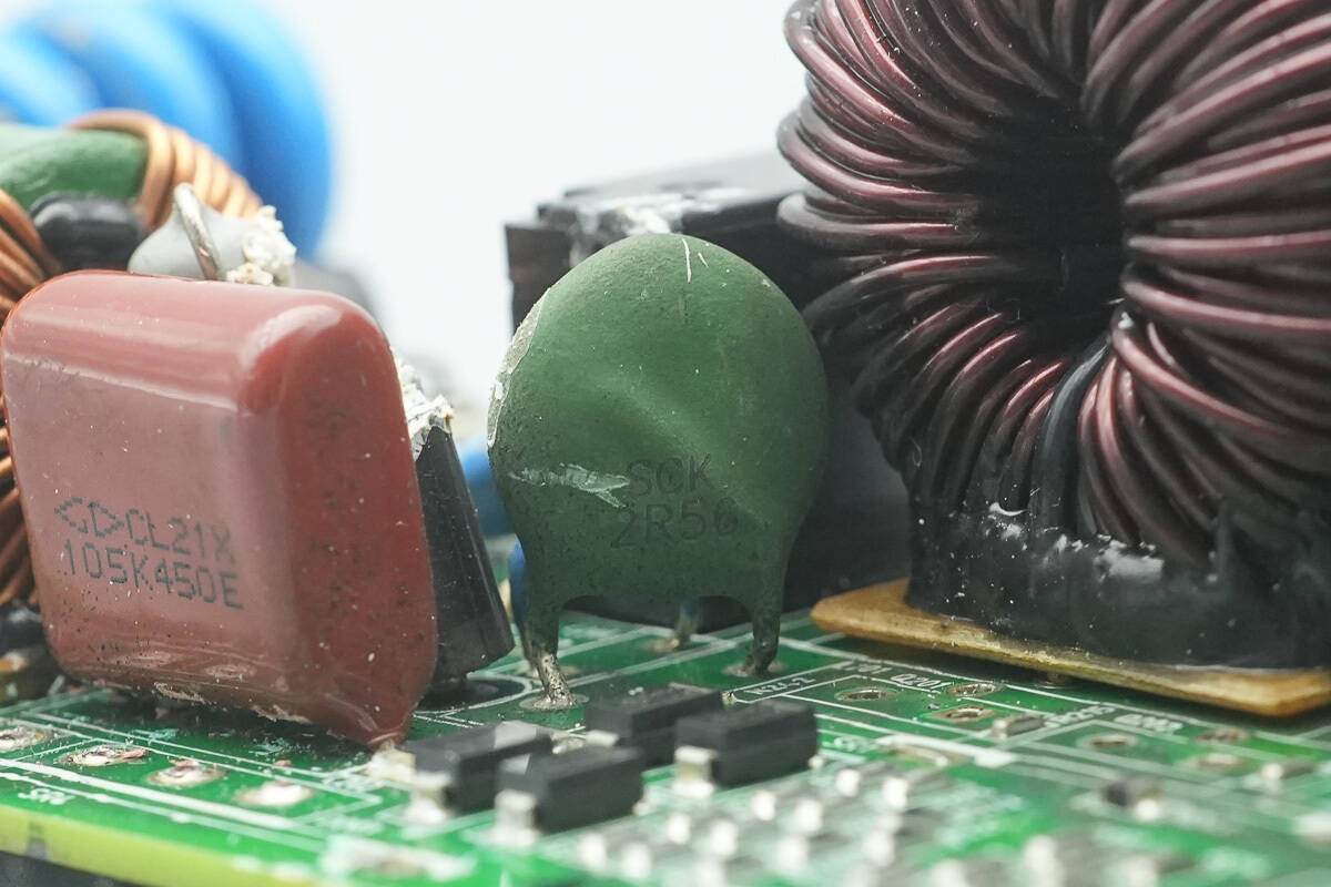
The NTC thermistor is marked SCK2R56.
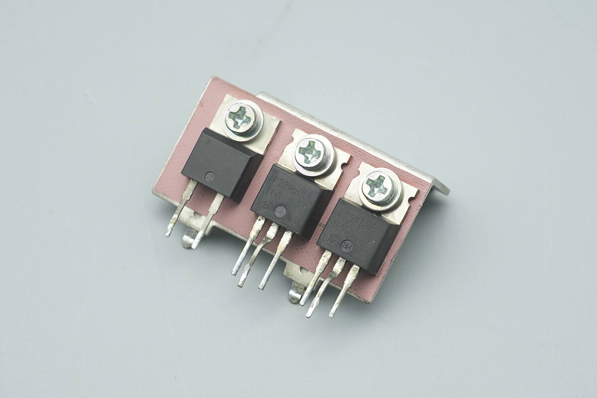
The PFC MOSFETs and PFC rectifier are mounted on this heatsink.
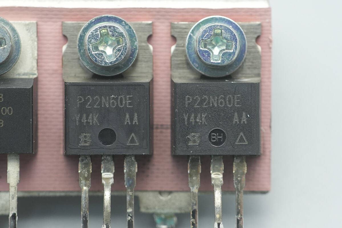
The PFC MOSFETs are from VISHAY, model SiHP22N60E, NMOS type, rated at 650 V with an on-resistance of 180 mΩ, and use a TO-220AB package.
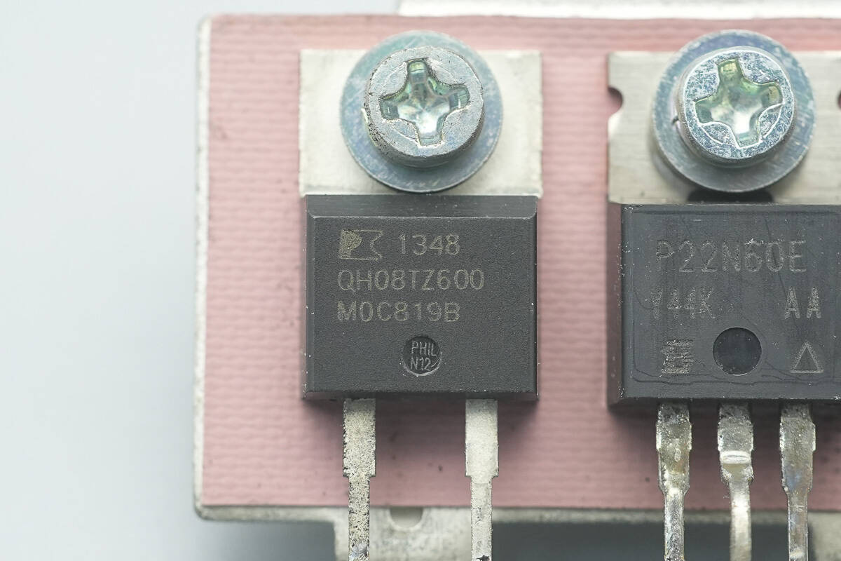
The PFC rectifier is from PI, model QH08TZ600, part of the QspeedH series of ultra-fast silicon diodes, rated at 600 V, 8 A, and uses a TO-220AC package.
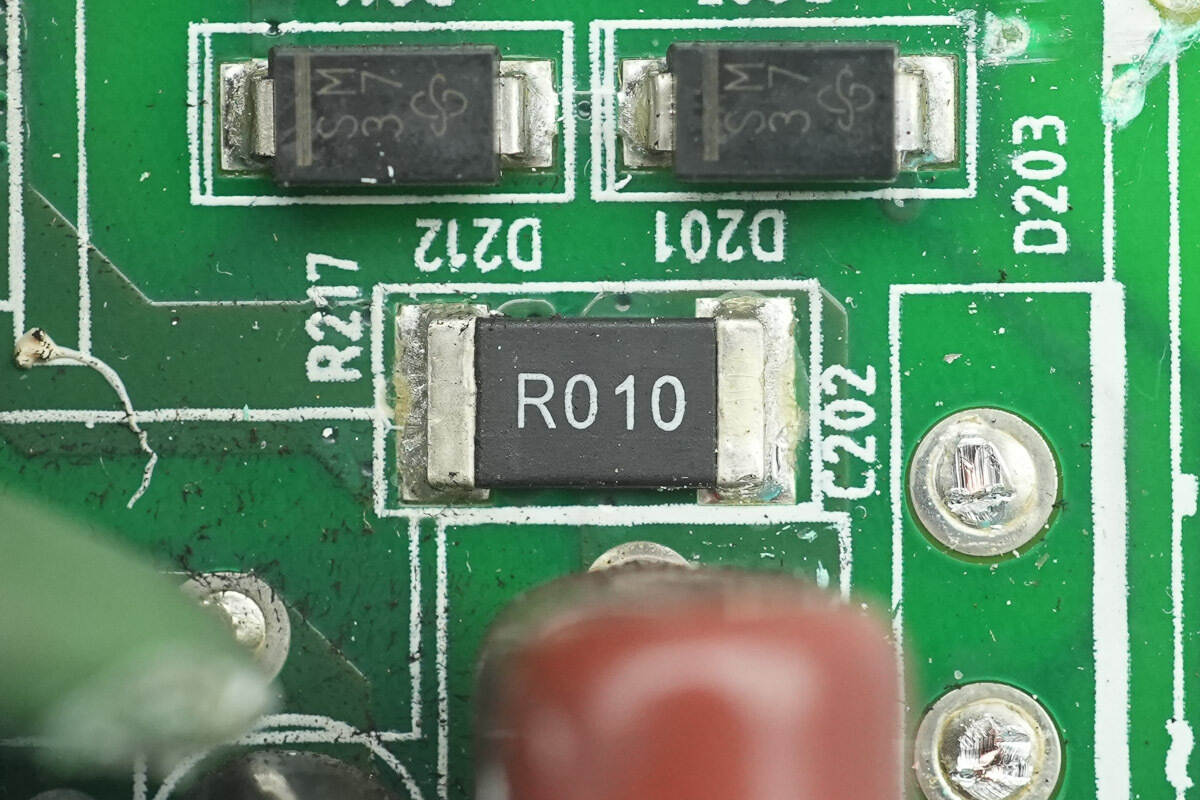
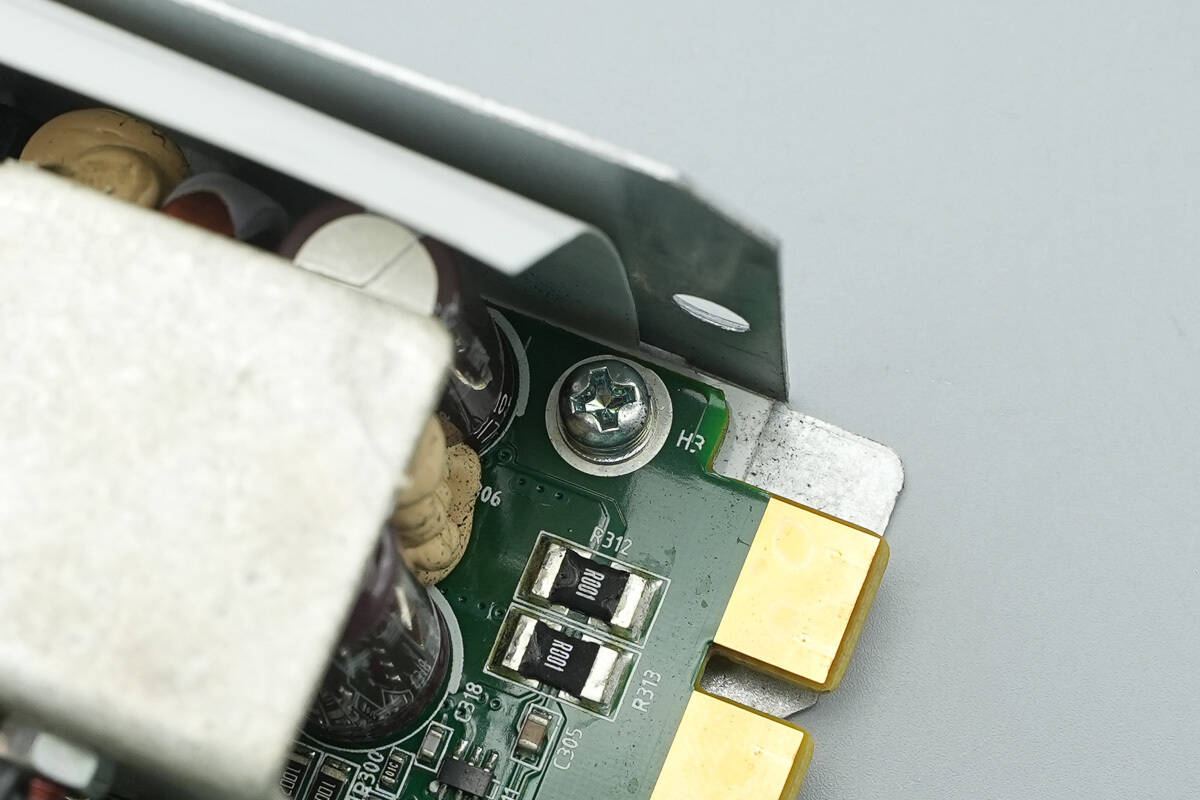
A 10 mΩ sense resistor is used to monitor the current of the PFC MOSFETs.
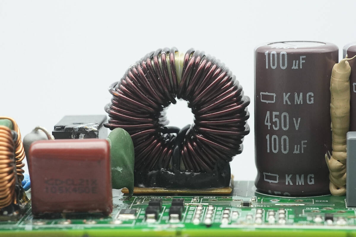
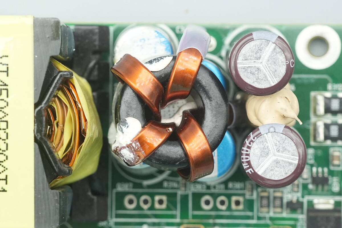
The PFC boost inductor is wound with enameled wire and has a bakelite insulating board at the base.
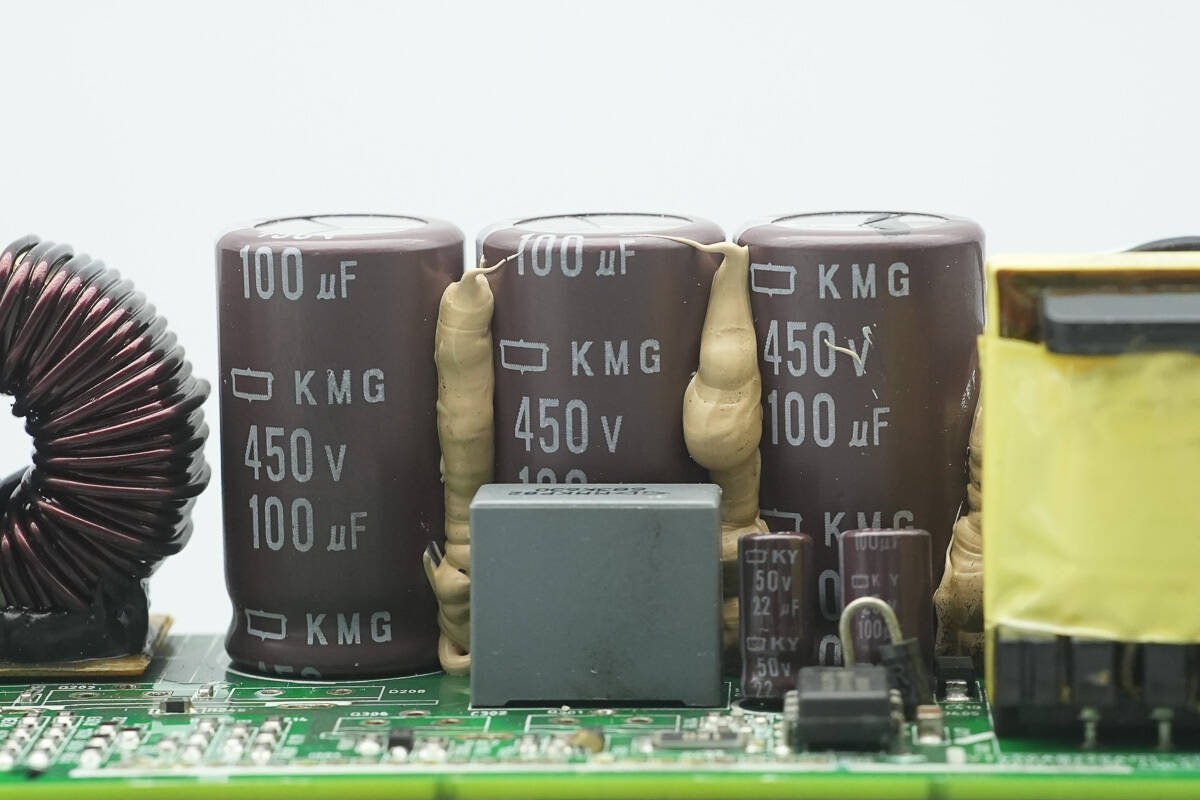
The high-voltage filter capacitors are from NCC, part of the KMG series of compact electrolytic capacitors, rated at 450 V, 100 μF, with three units connected in parallel.
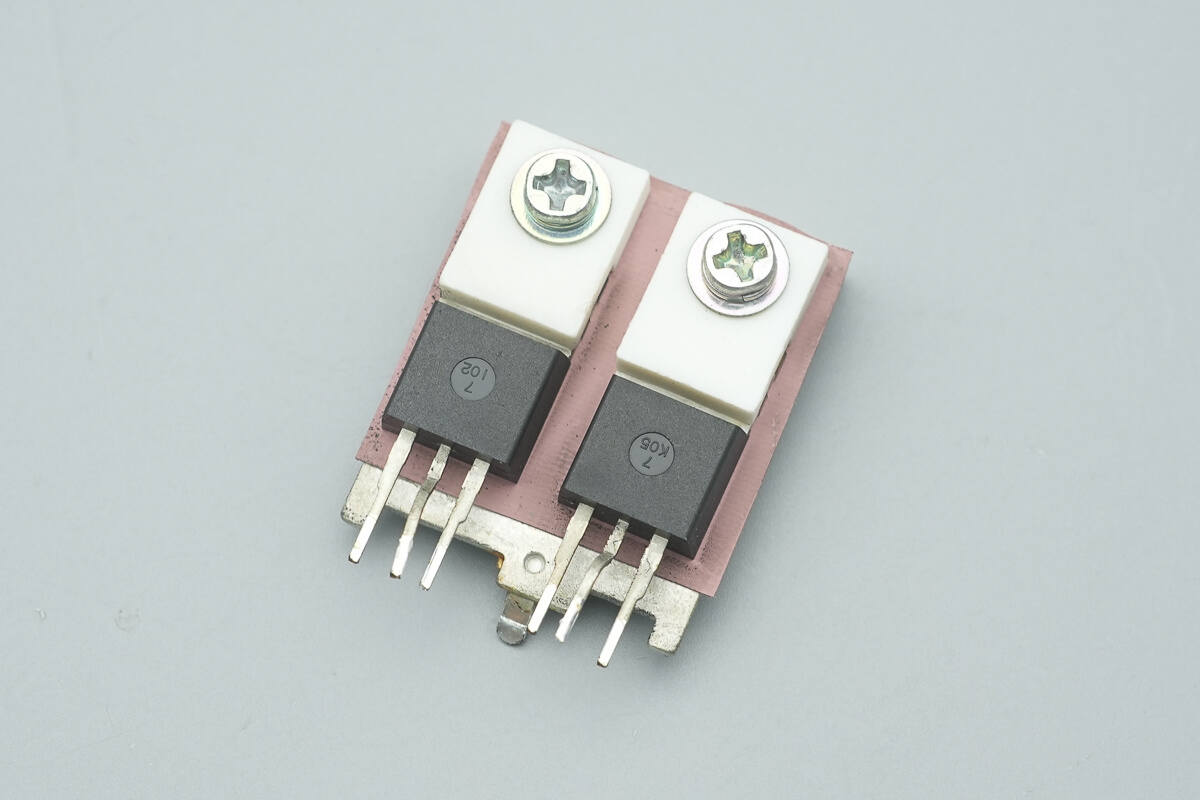
The LLC MOSFETs are mounted on the heatsink.
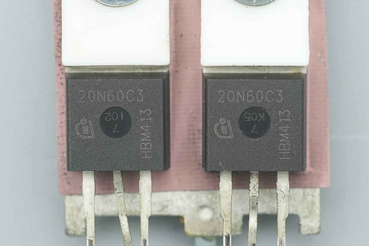
The LLC MOSFETs are from Infineon, marked 20N60C3, model SPP20N60C3, NMOS type, rated at 650 V with an on-resistance of 190 mΩ, and use a TO-220 package.
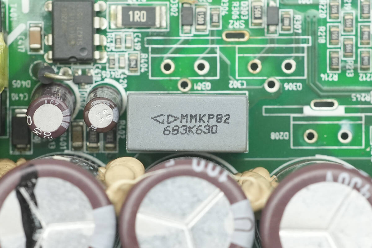
The resonant capacitor is rated at 0.068 μF, 630 V.
Close-up of the resonant inductor.
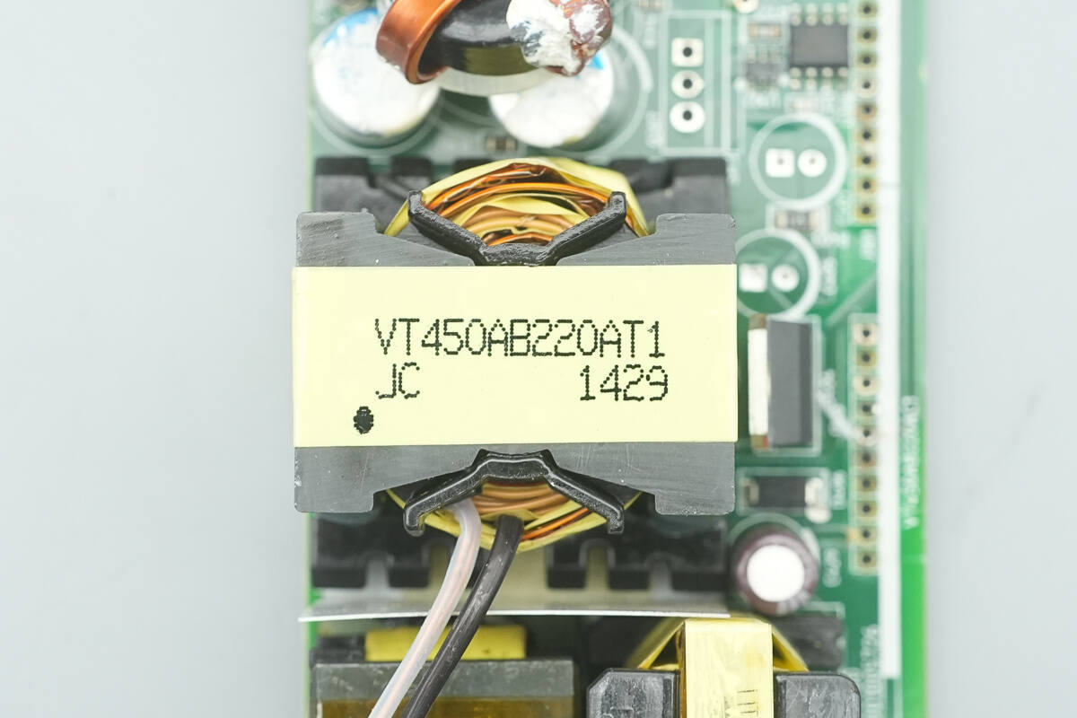
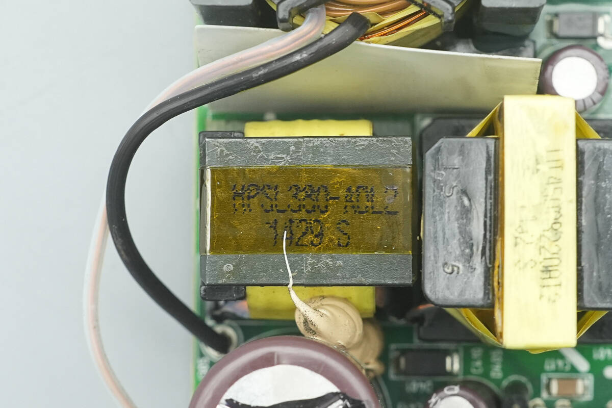
Close-up of the LLC transformer.
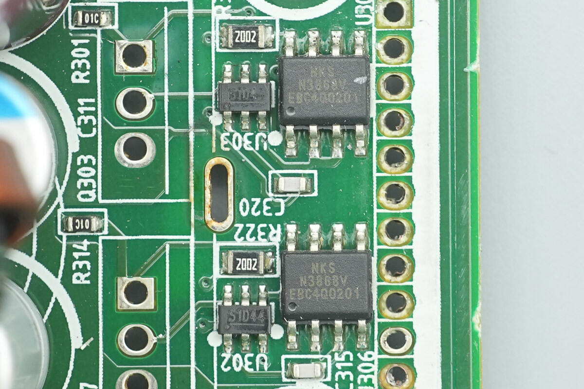
Close-up of the synchronous rectifier controller and current sensor.
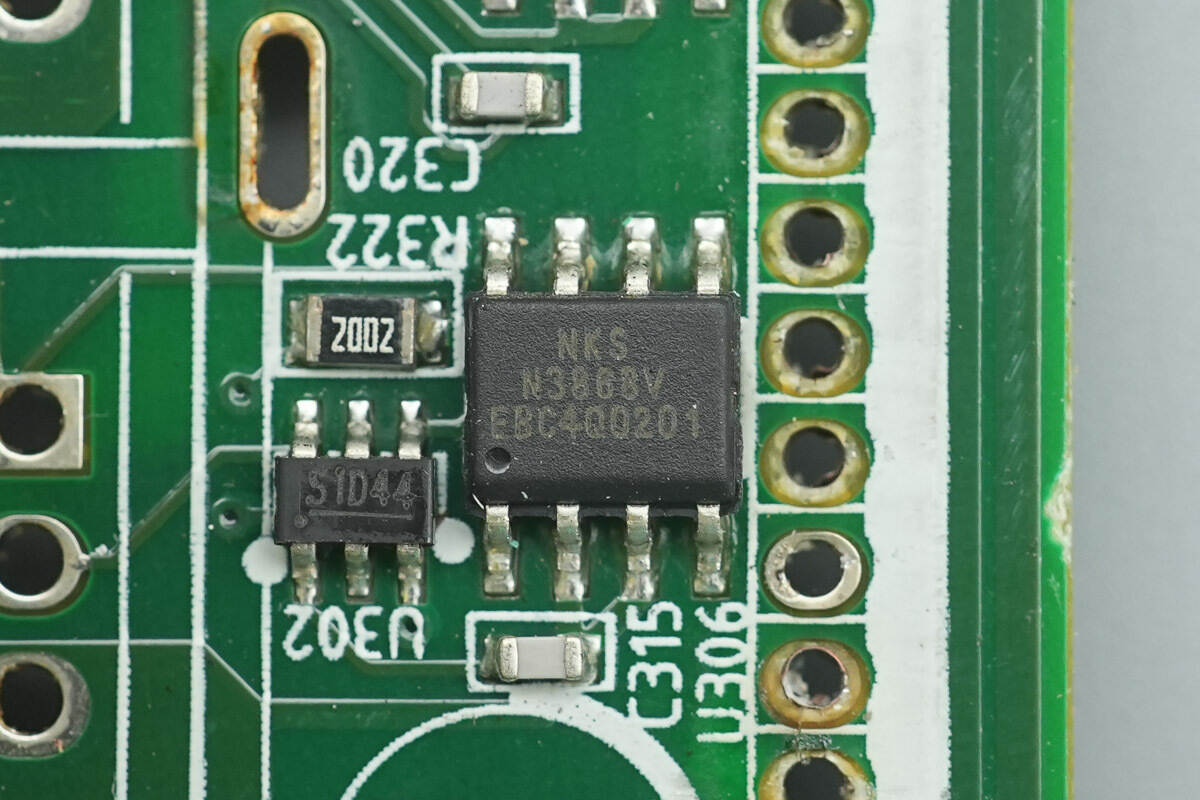
The synchronous rectifier controller is from NIKO-SEM, model N3868V, supporting CCM and DCM modes, suitable for both fixed-frequency and variable-frequency applications, and comes in an SOP-8 package.
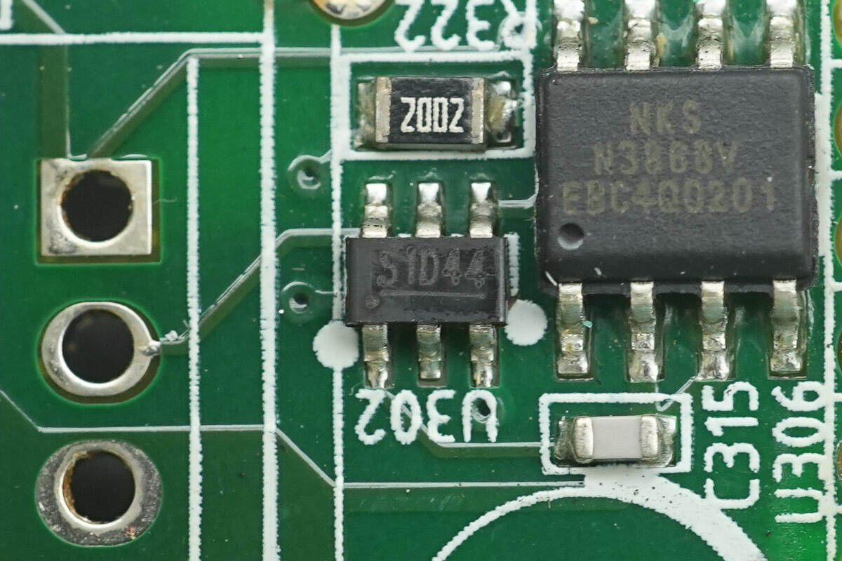
The current sensor is from NIKO-SEM, marked S1, model N3869M, designed for synchronous rectification applications, and comes in a SOT-26 package.
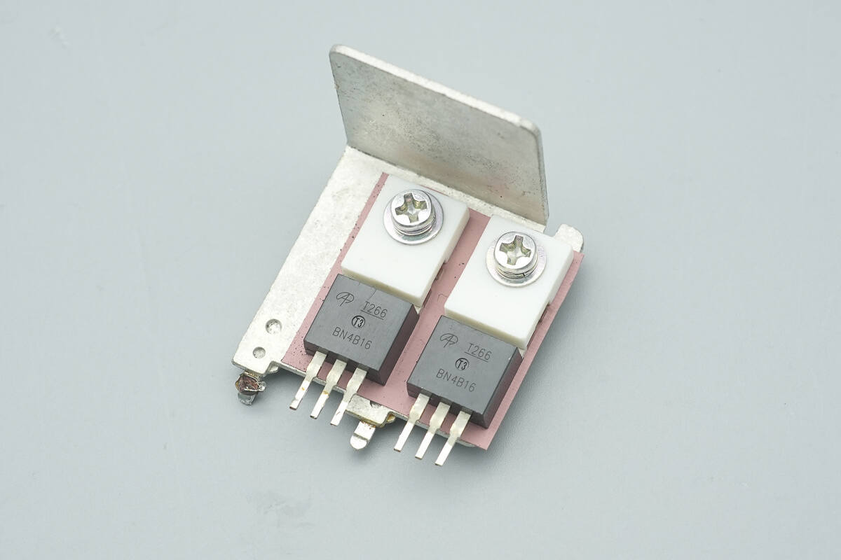
The synchronous rectifiers are mounted on the heatsink.
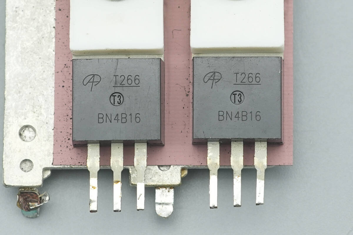
The synchronous rectifiers are from AOS, model AOT266L, NMOS type, rated at 60 V with an on-resistance of 2.9 mΩ, and use a TO-220 package.
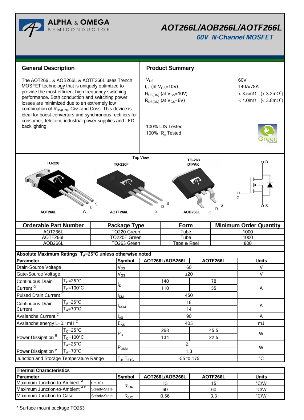
Here is the information about AOS AOT266L.
Solid capacitors are placed beneath the filter inductor.
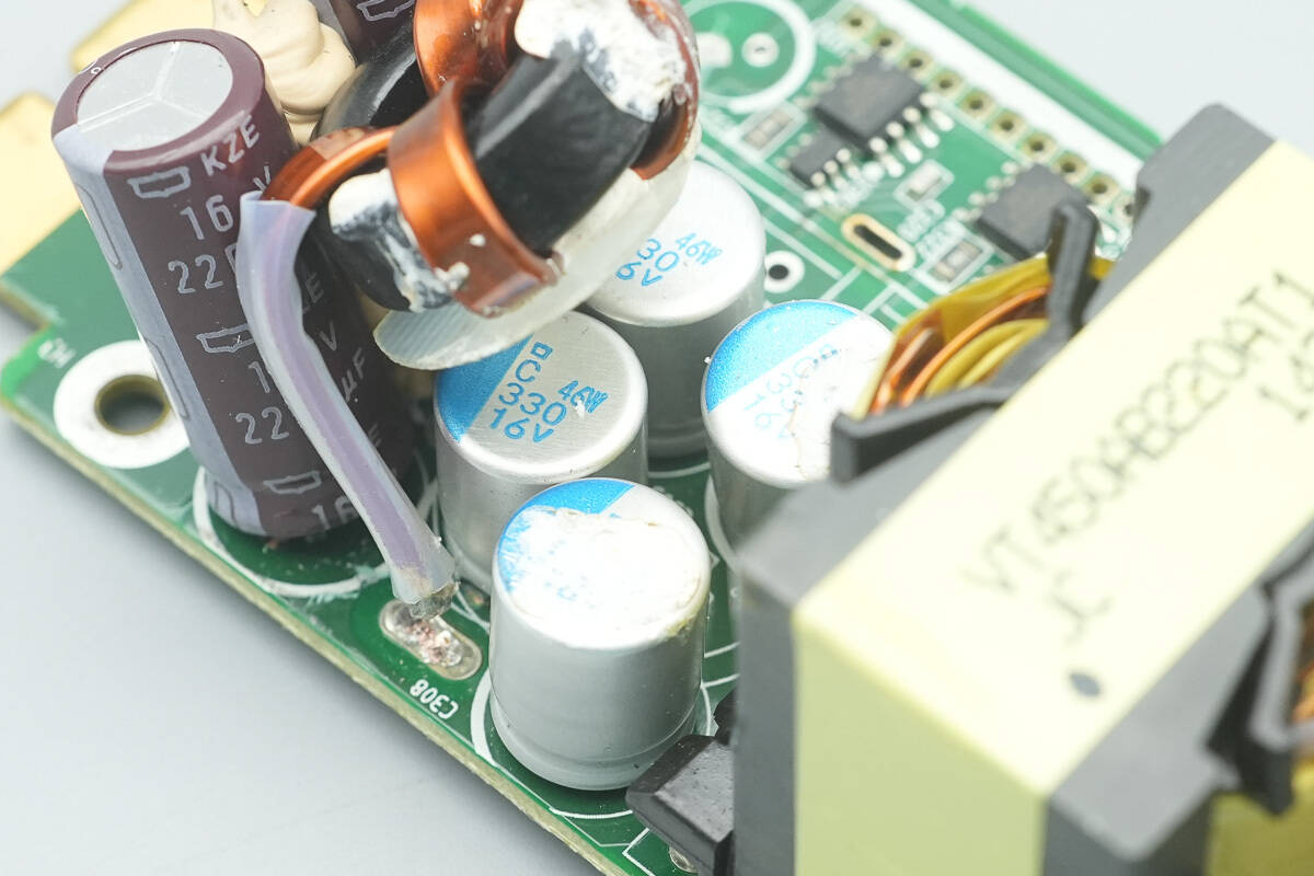
The solid capacitors are from NCC, part of the PSC series of conductive polymer aluminum electrolytic capacitors, rated at 330 μF, 16 V, with four units connected in parallel.
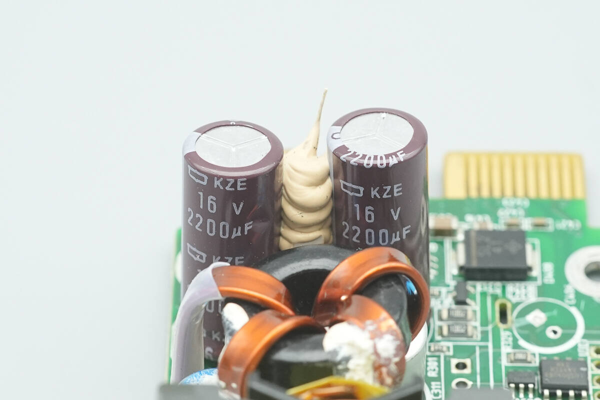
The filter capacitors are from NCC, part of the KZE series of long-life aluminum electrolytic capacitors, rated at 16 V, 2200 μF, with two units connected in parallel.
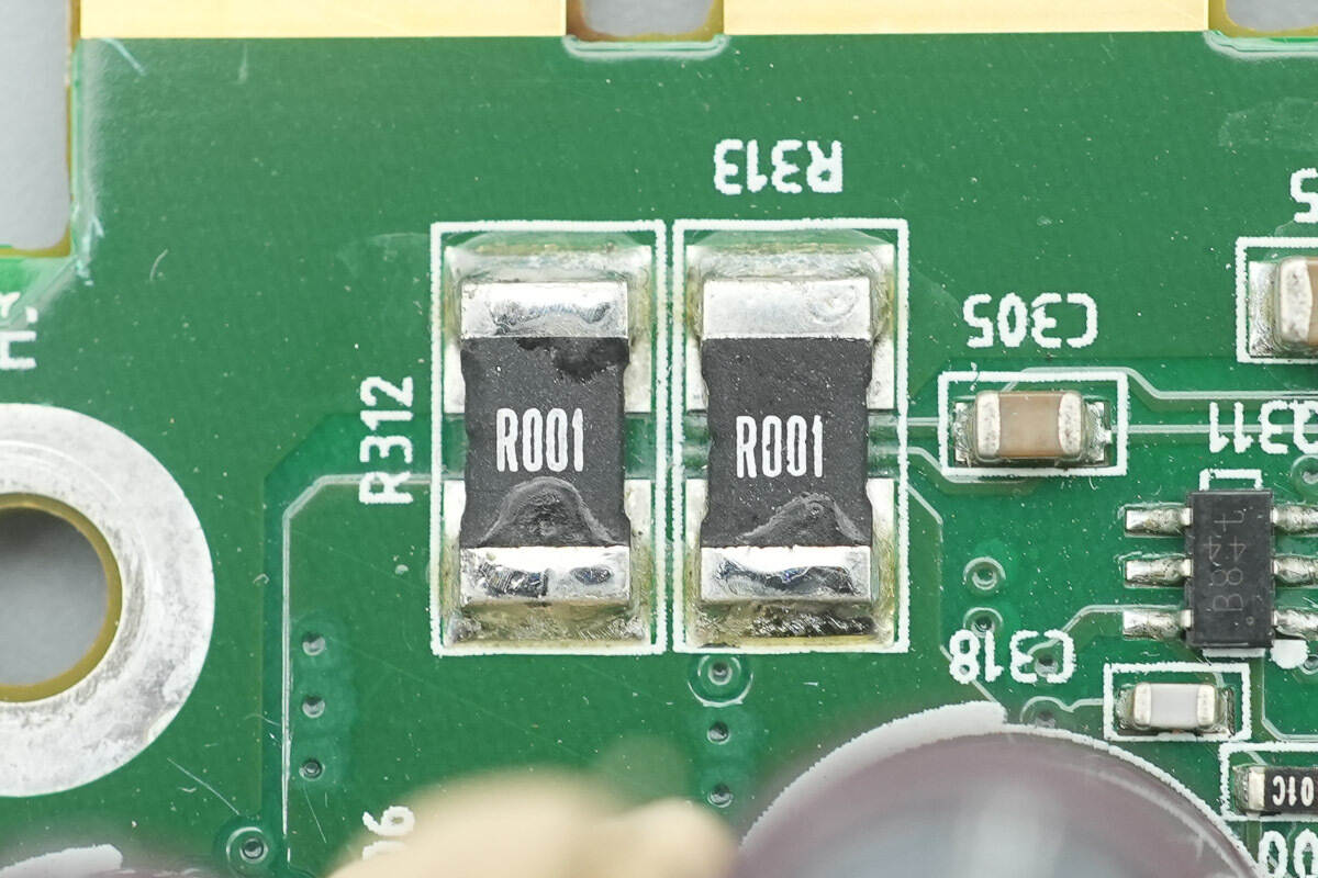
1 mΩ sense resistors are used to monitor the output current.
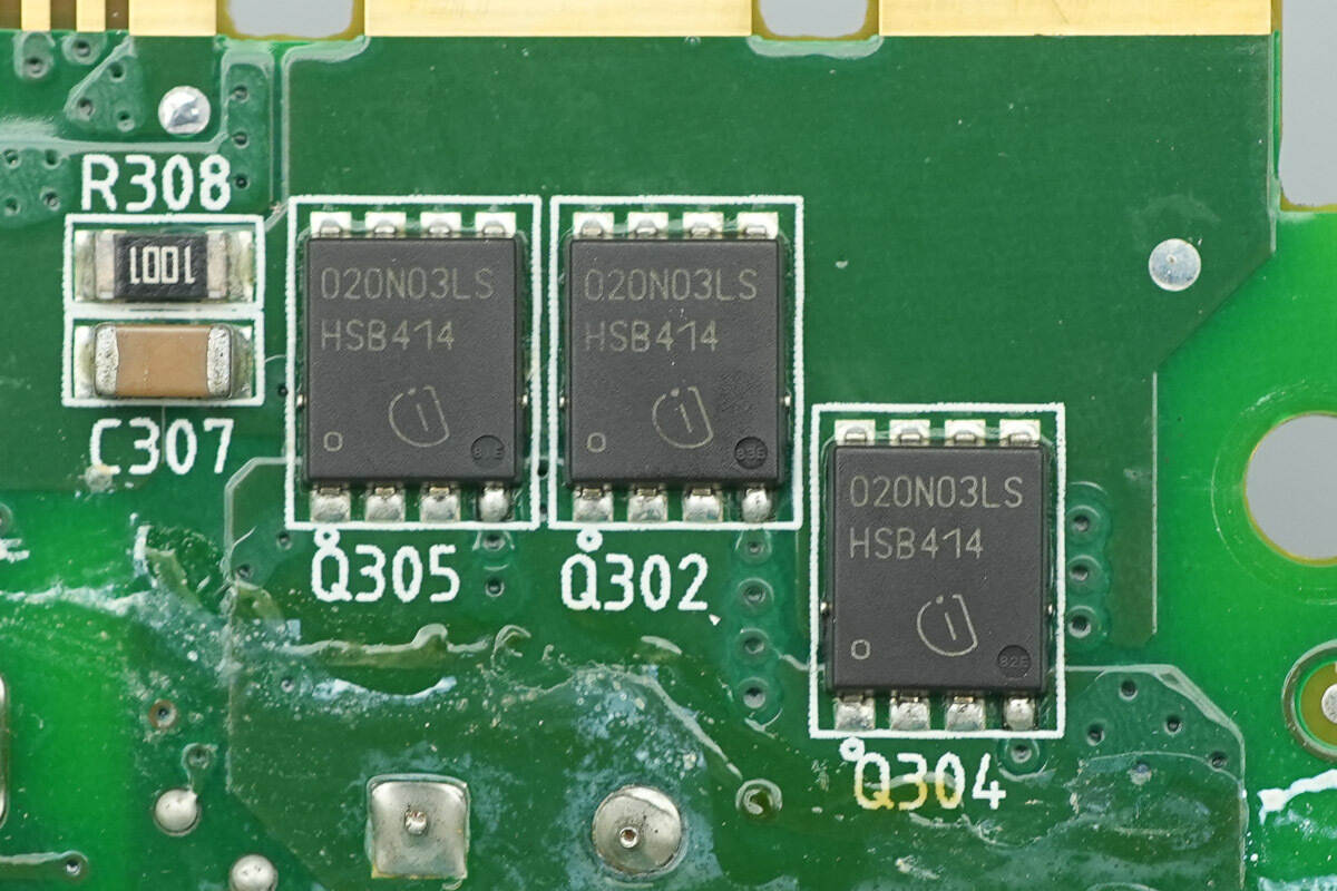
The output control MOSFETs are from Infineon, marked 020N03LS, model BSC020N03LSG, NMOS type, rated at 30 V with an on-resistance of 2 mΩ, and use a TDSON-8 package.
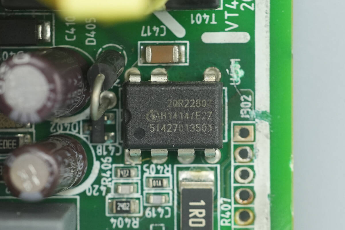
The standby power supply chip is from Infineon, model ICE2QR2280Z, with an integrated 800 V MOSFET, supporting 31 W output power over a wide voltage input range, and comes in a DIP-7 package.
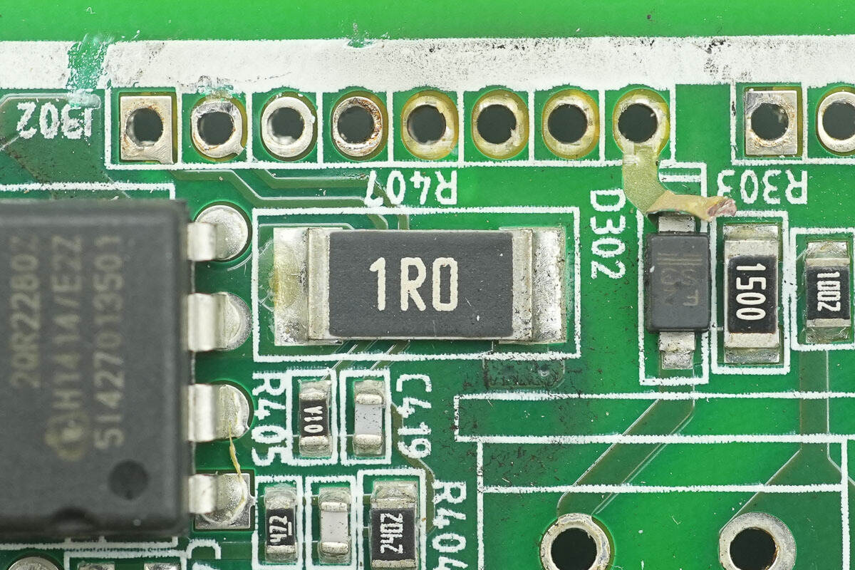
A 1 Ω resistor is used to sense the current of the internal MOSFET of the chip.
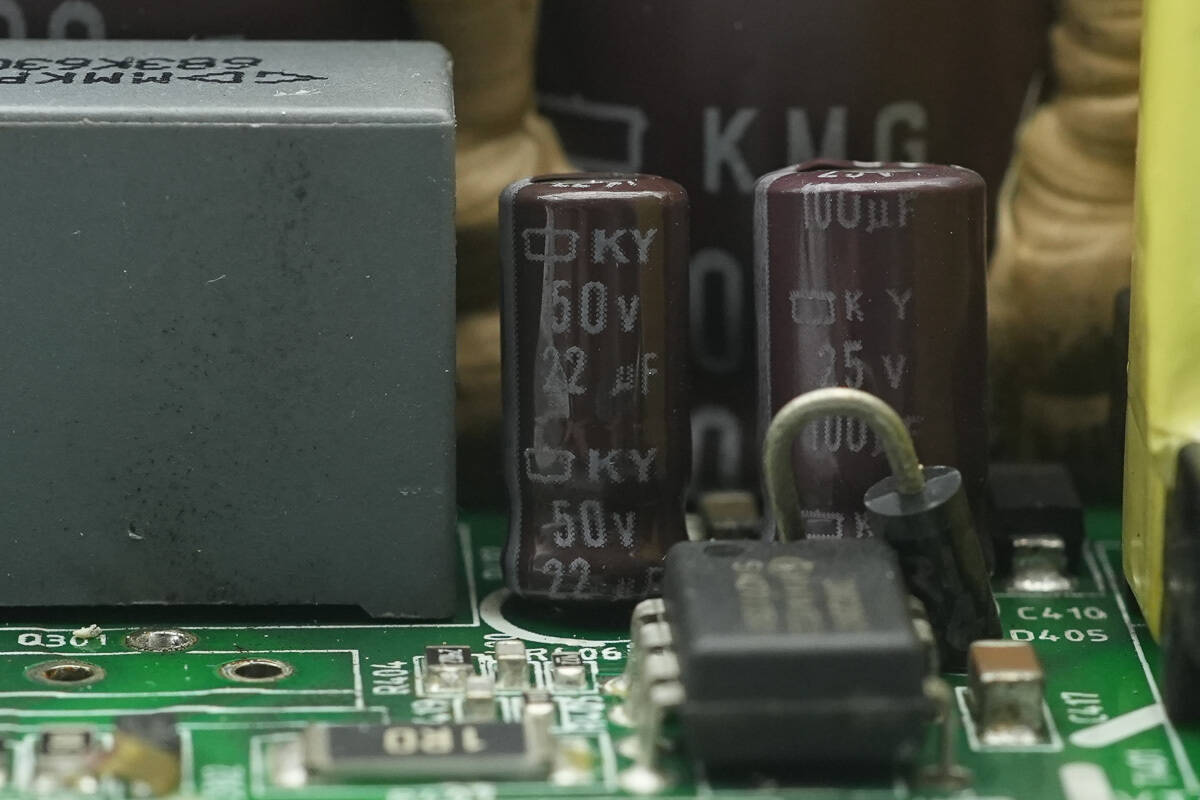
The filter capacitor supplying power to the master control chip is from NCC, rated at 50 V, 22 μF.
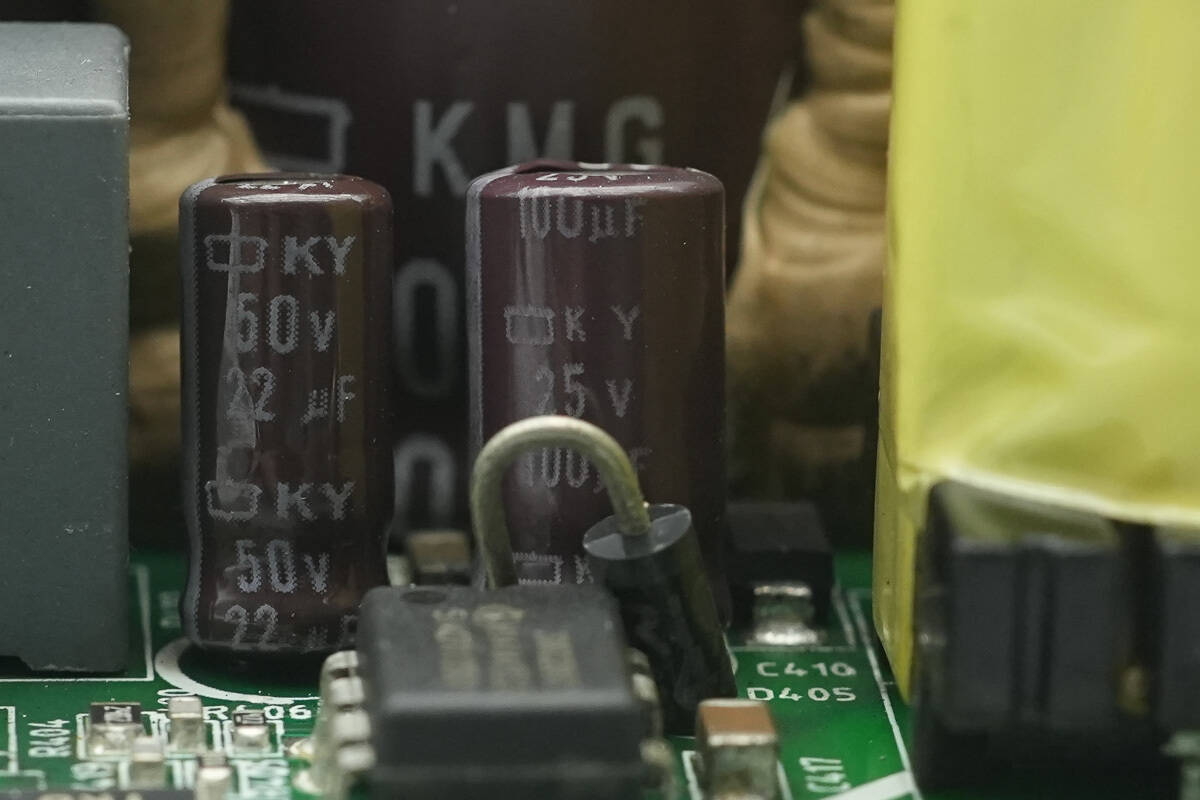
Another filter capacitor is rated at 25 V, 100 μF.
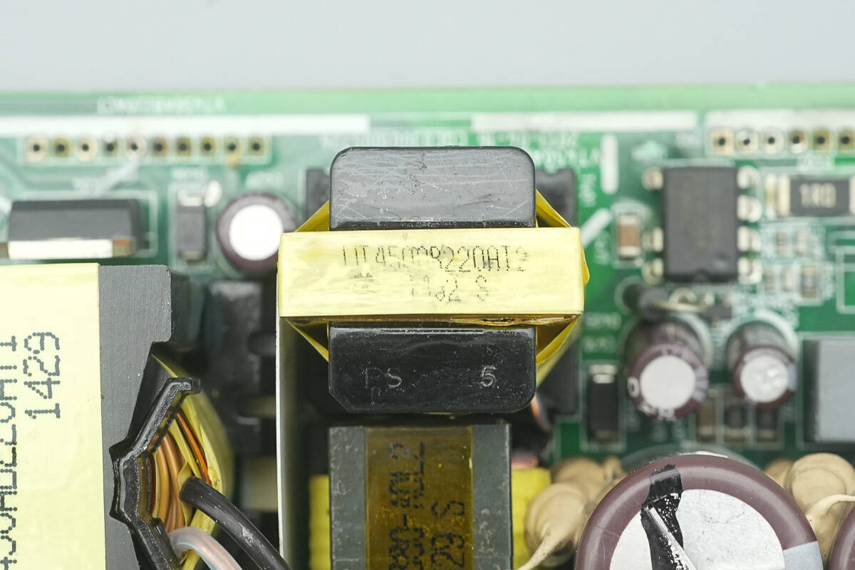
Close-up of the standby power transformer.
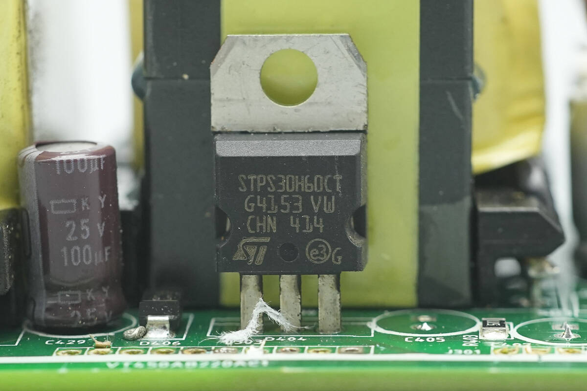
The rectifier is from STMicro, model STPS30H60CT, a Schottky diode rated at 60 V, 30 A, and uses a TO-220AB package.
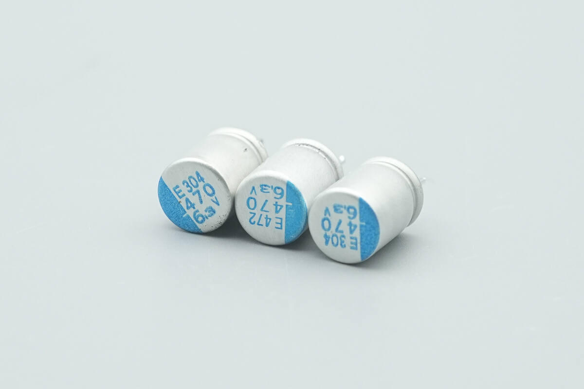
The filter capacitors are from NCC, part of the PSE series of conductive polymer aluminum electrolytic capacitors, rated at 470 μF, 6.3 V, with three units connected in parallel.
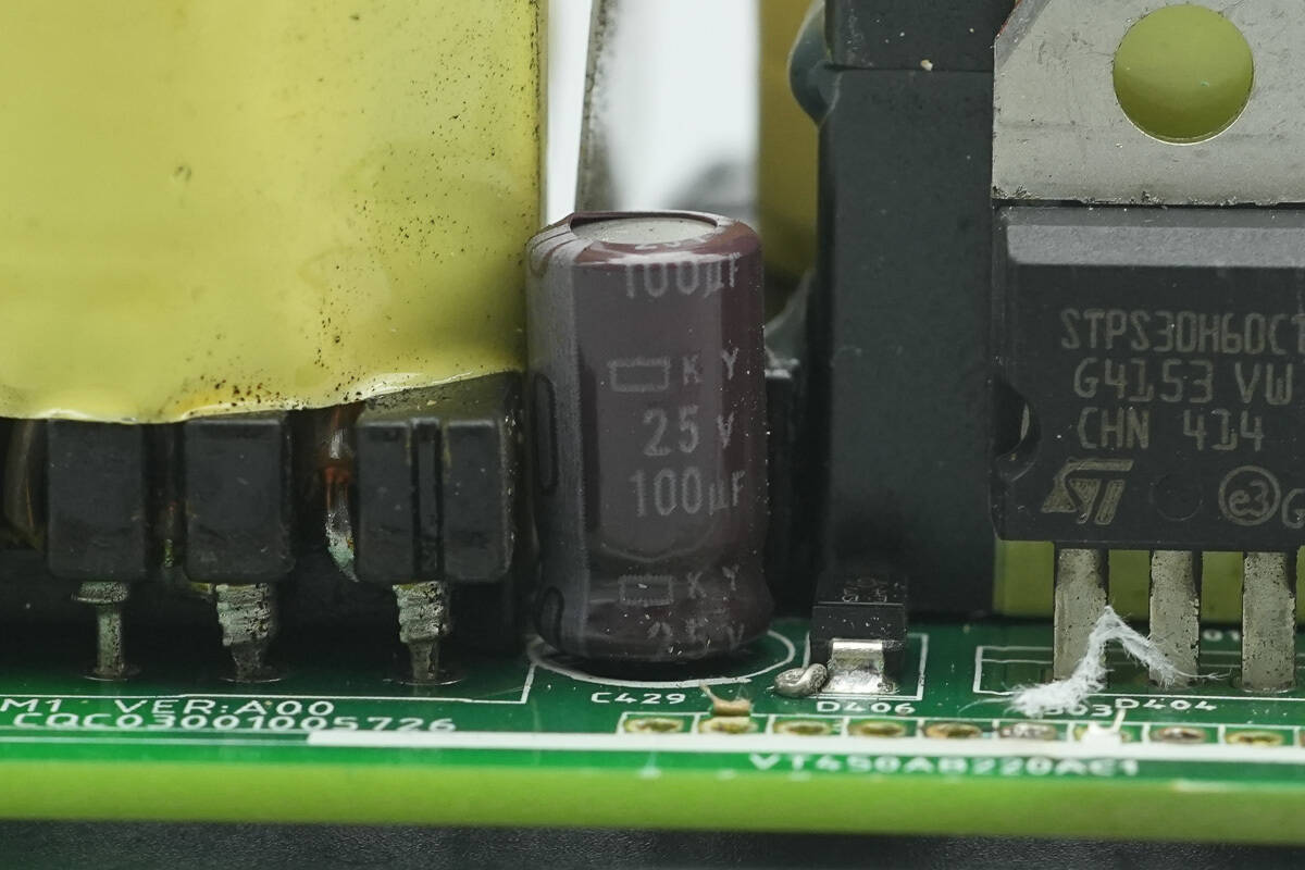
The filter capacitor is rated at 25V 100μF.
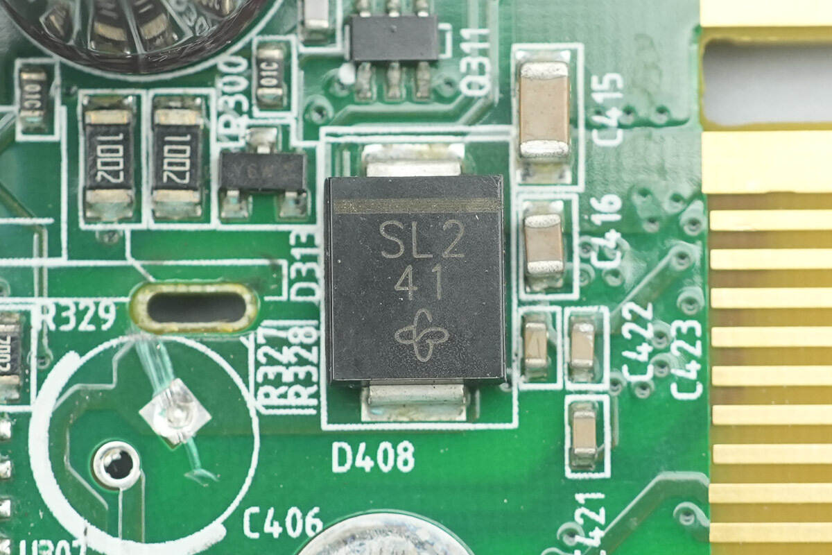
The diode is from VISHAY, marked with SL2, model SL42, specification 20V4A, and uses an SMC package.
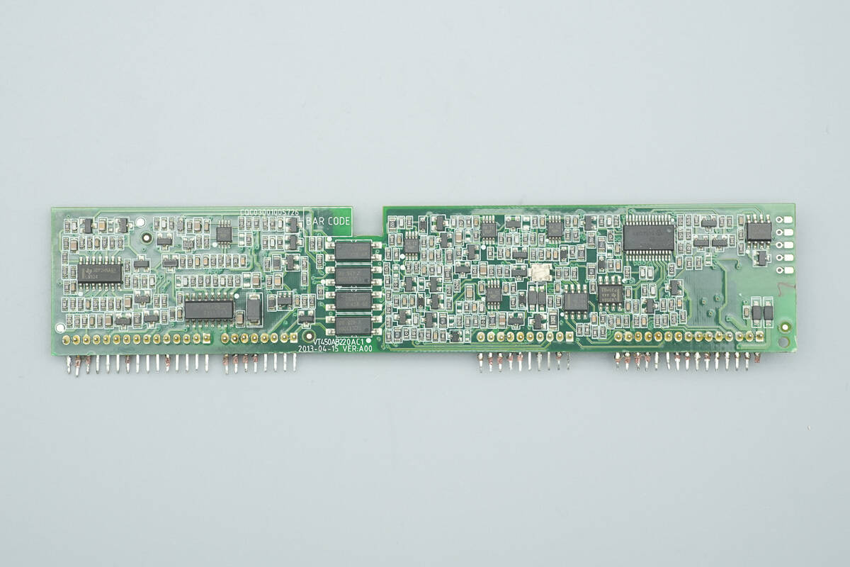
The control PCB features operational amplifiers, a voltage comparator, an LLC controller, feedback optocouplers, an MCU, and memory.
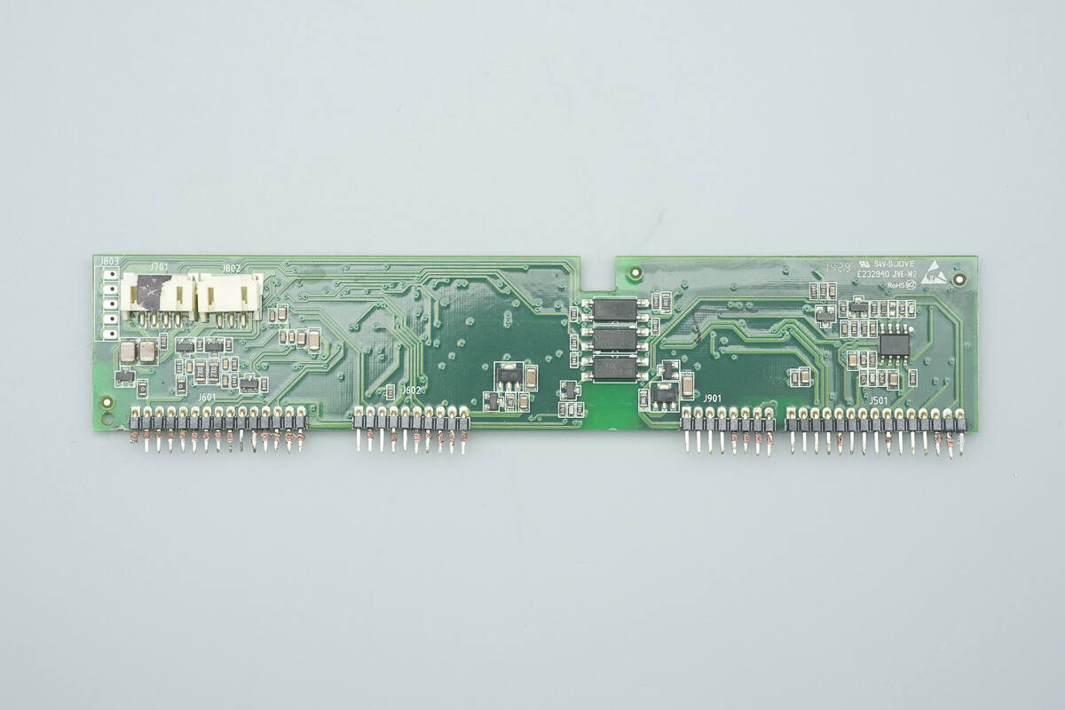
The inner side is equipped with feedback optocouplers and a PFC controller.
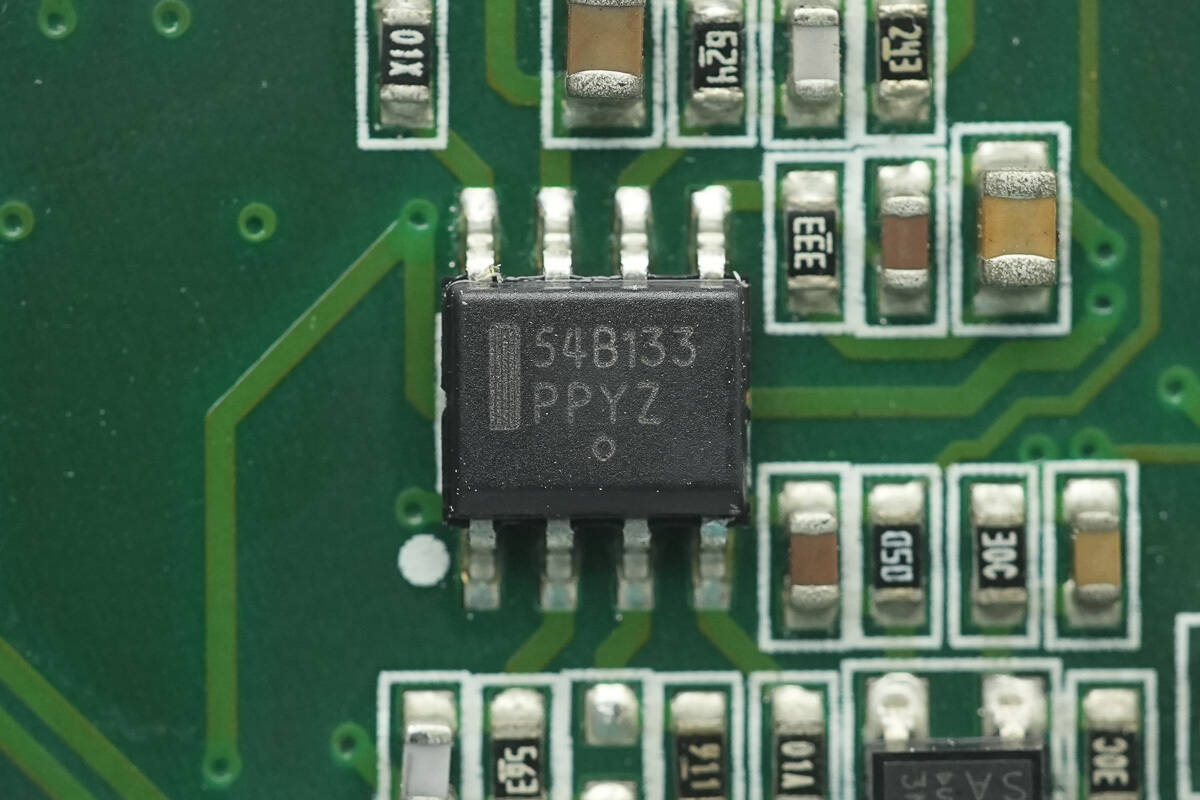
The PFC controller from Onsemi, marked with 54B133 and model NCP1654, is a continuous conduction mode PFC boost controller. It operates in fixed frequency mode, with the on-time controlled by the instantaneous inductor current. The chip features a simplified set of external components, programmable overcurrent protection, and comprehensive protection functions. It comes in an SO-8 package.
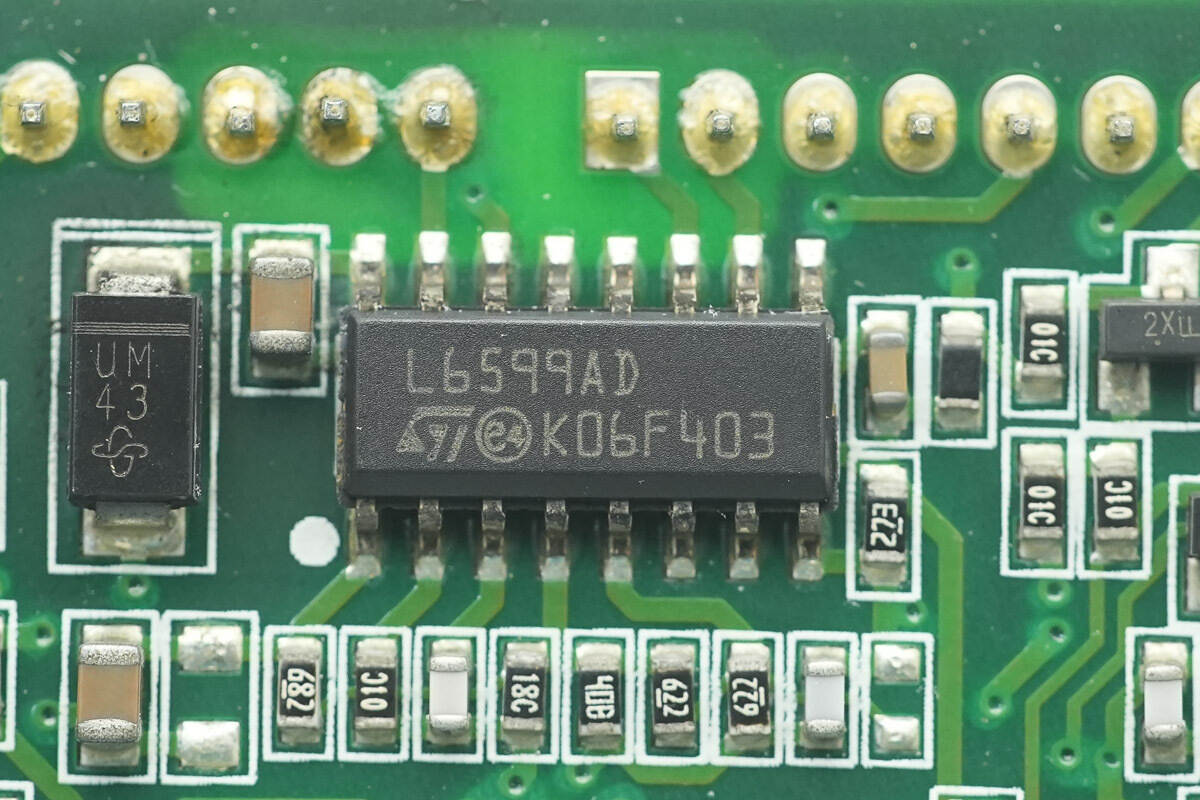
The LLC controller from STMicro, model L6599A, is a fixed 50% duty cycle half-bridge controller. It features an integrated 600V high-side driver and synchronous DMOS, eliminating the need for an external bootstrap diode. The L6599A supports switching frequencies up to 500 kHz and PFC control, and comes in an SO16N package.
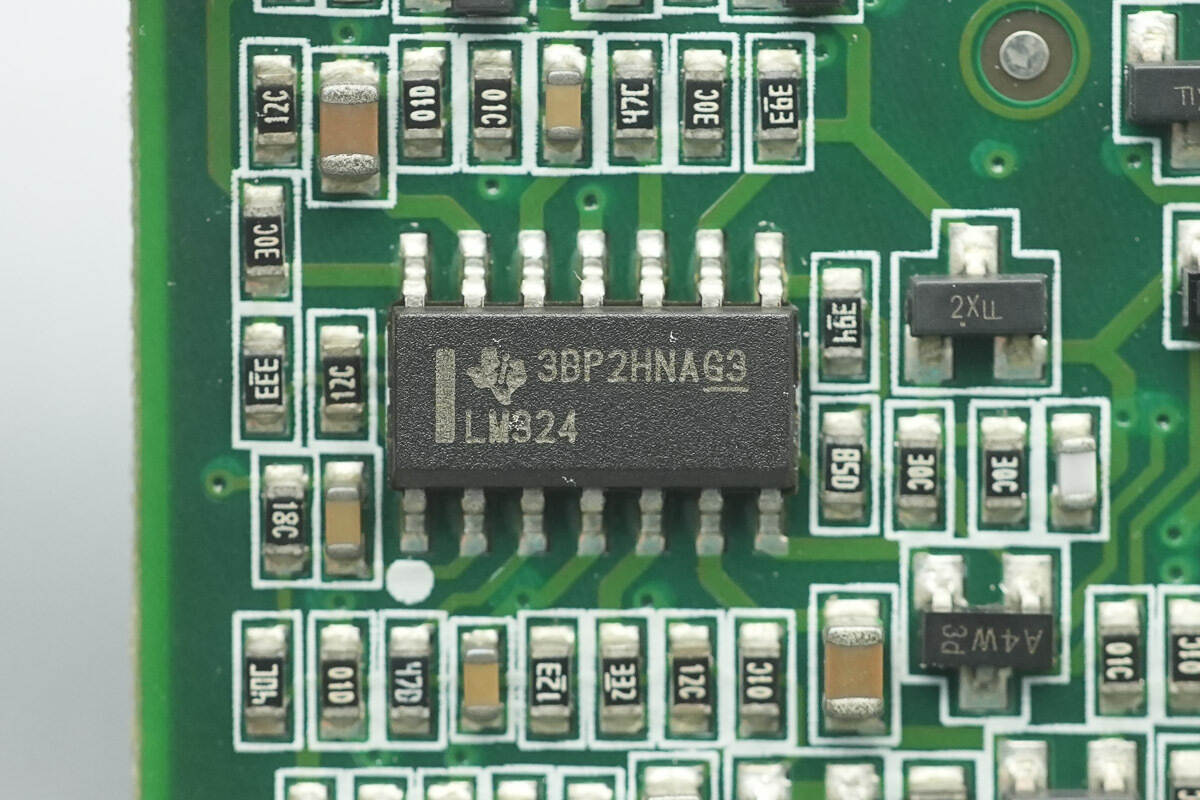
The operational amplifier from STMicro, model LM324, is a general-purpose quad op-amp in an SO14 package.
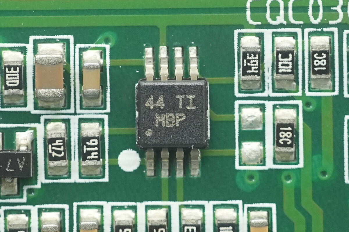
The operational amplifier from TI, marked with MBP and model LM2904, is a dual-channel op-amp supporting up to 26 V operation. It comes in a VSSOP-8 package.
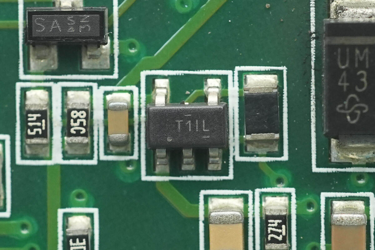
The voltage comparator from TI, marked with T1IL and model TL331, is a high-voltage single-channel differential comparator in a SOT23-5 package.
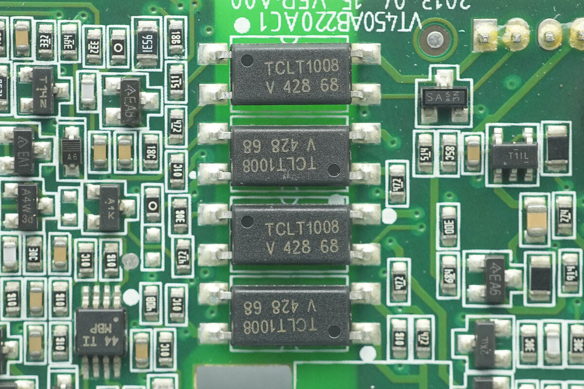
The isolated optocouplers are from Vishay, model TCLT1008.
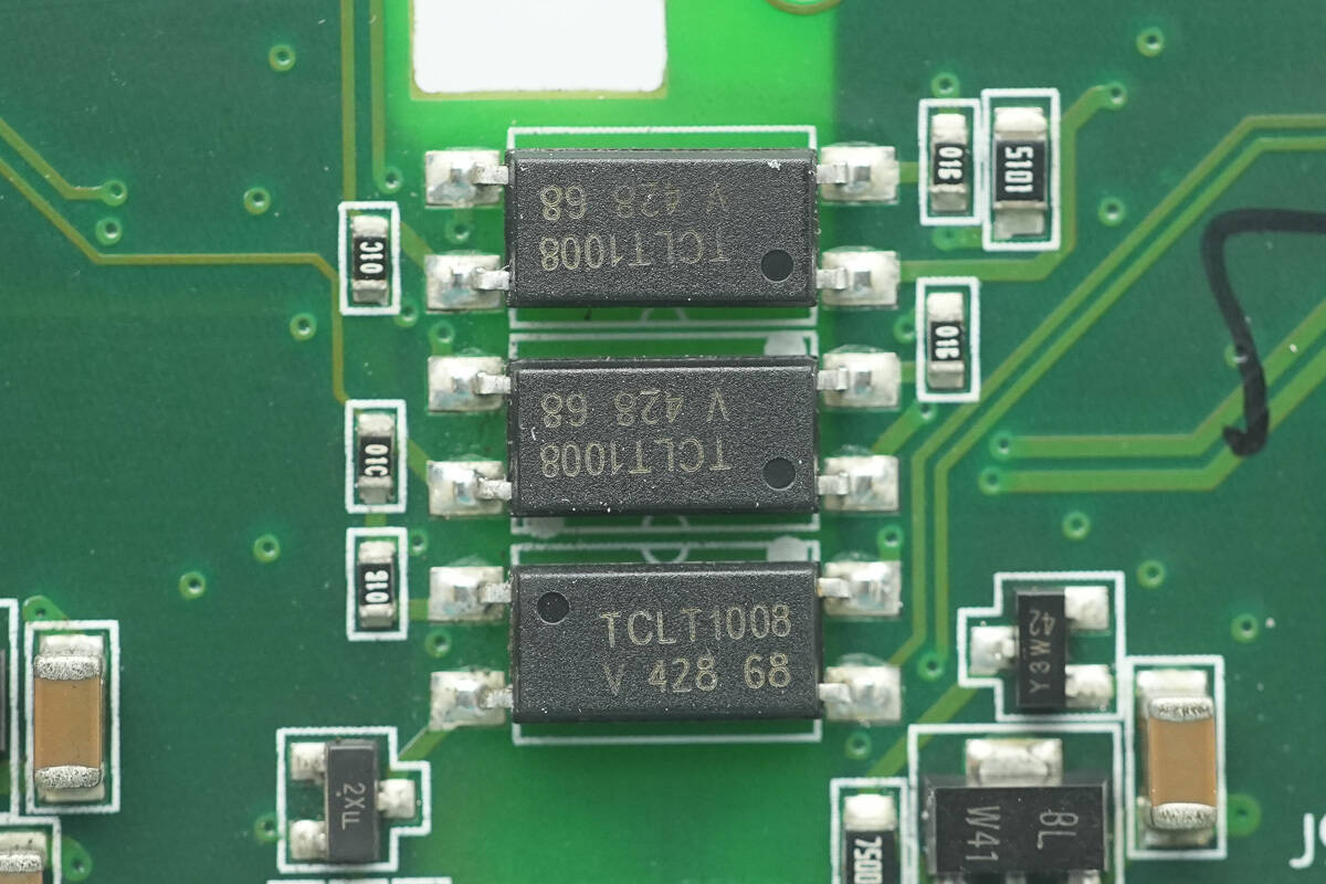
Three additional isolated optocouplers of the same model are also located on the back side.
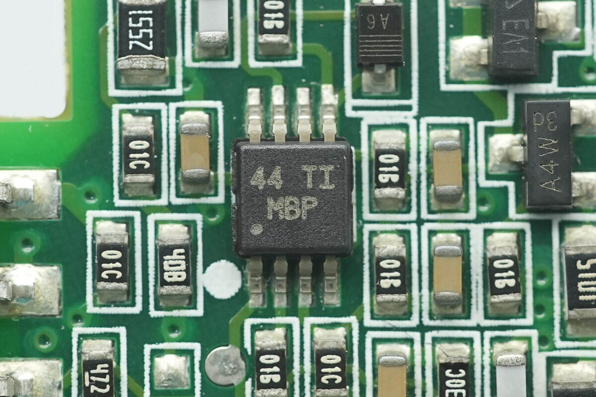
There is a TI LM2904 op-amp, with a total of four units located on the back side.
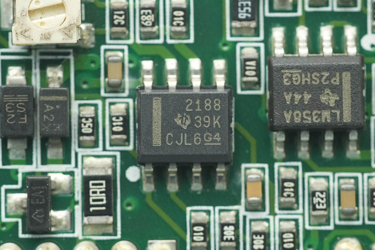
The operational amplifier from TI, model OPA2188, is a low-noise, zero-drift op-amp with rail-to-rail output and a 36 V supply rating. It comes in an SOIC-8 package.
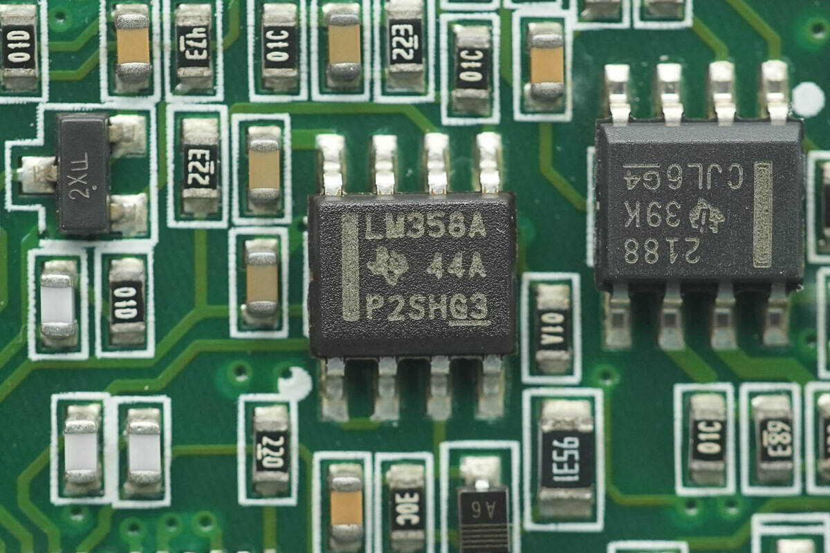
The operational amplifier from TI, model LM358A, is a dual-channel op-amp in an SOIC-8 package.
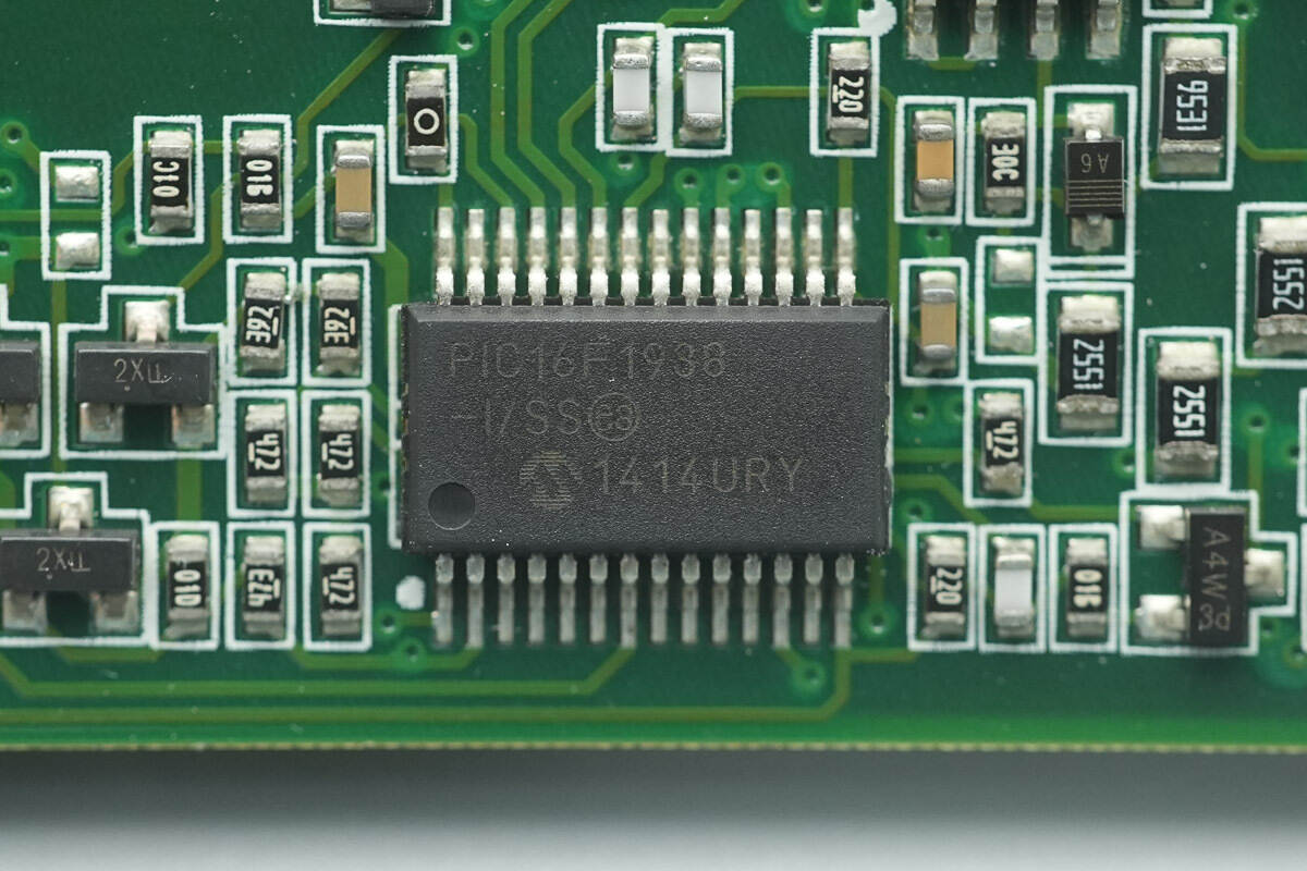
The MCU from Microchip, model PIC16F1938, features a high-performance RISC CPU with 28 KB of Flash, 1 KB of SRAM, and 256 B of EEPROM. It comes in an SSOP-28 package.
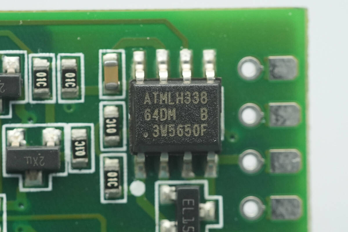
The memory from Microchip, marked with 64D and model AT24C64D, has a capacity of 8 KB and supports an operating voltage range of 1.7–5.5 V. It comes in an SOIC-8 package.
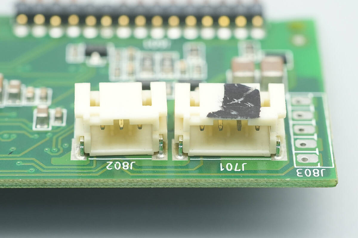
Close-up of the connectors for the LED indicator and cooling fan.
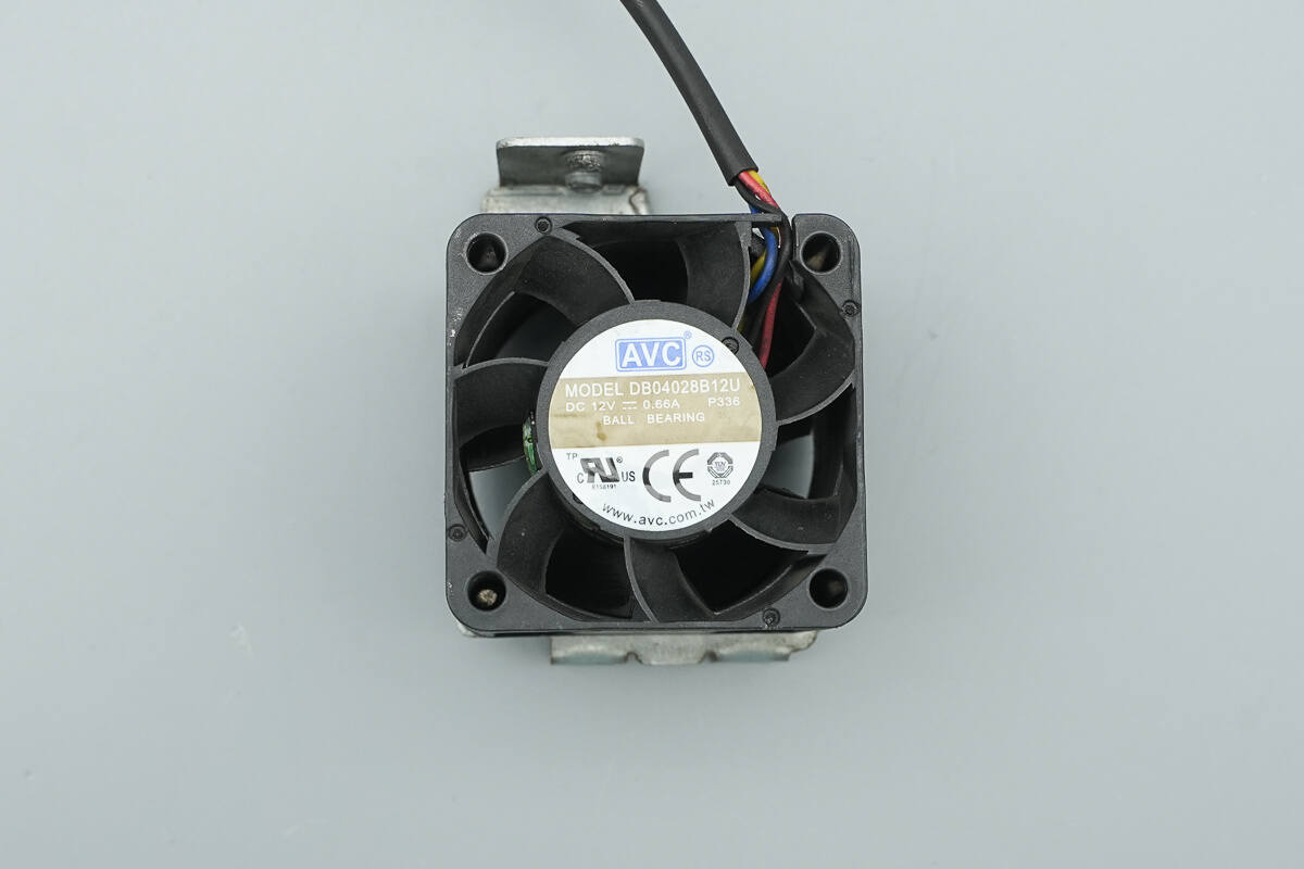
The cooling fan from AVC, model DB04028B12U, is rated at 12 V and 0.66 A. It features a ball bearing design and includes stationary guide vanes.

Well, those are all components of the VMAX AC Power Supply.
Summary of ChargerLAB
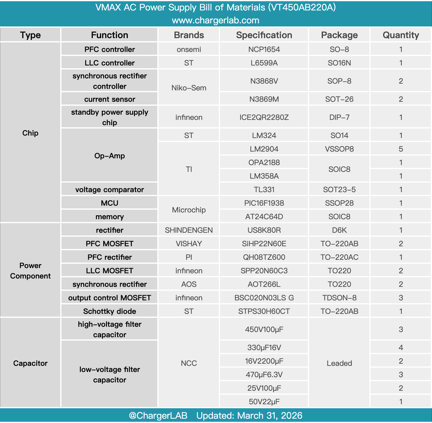
Here is the component list of the VMAX AC Power Supply for your convenience.
The server power supply, model VT450AB220A, supports an input range of 100–240 V AC. It provides a 12 V output at 37 A, along with an additional 5 V output at 3 A, for a total output power of 459 W. A cooling fan is installed inside the unit, drawing air in from the DC output side and exhausting it through the AC input side for heat dissipation.
After taking it apart, we found that it adopts a PFC + LLC + synchronous rectification architecture. The PFC stage is controlled by an Onsemi NCP1654, while the LLC stage uses an STMicro L6599A, with a NIKO-SEM N3868V for synchronous rectification control.
The PFC MOSFETs are Vishay SiHP22N60E, and the PFC rectifier is a PI QH08TZ600. The LLC MOSFETs are Infineon SPP20N60C3, and the synchronous rectifiers are AOS AOT266L. The standby power supply uses an Infineon ICE2QR2280Z, and a Microchip PIC16F1938 MCU is employed for communication control. All electrolytic capacitors are from NCC. Key components are reinforced with adhesive, reflecting solid build quality and reliable component selection.
Related Articles:
1. Teardown of OPPO 120W SuperVOOC GaN Charger (OSABBCBBAC)
2. Teardown of OnePlus 100W SuperVOOC GaN Charger (VCBAOBCH)
3. Teardown of Anker Nano 5000mAh Magnetic Power Bank (A1665)