Introduction
Today, we will be disassembling a 3500W rectifier module from Vertiv. The model is R48-3500e3, which supports an input voltage range of 200-277Vac, with an output of -48V DC and a power output of 3500W.
The module utilizes DSP control and features a CAN bus interface. It adopts a bidirectional switch topology with a non-bridge PFC circuit, a full-bridge LLC resonant converter, and synchronous rectification architecture. Below, we will take a closer look at the internal design and components used in this rectifier module.
Product Appearance

The housing is made of aluminum alloy and features an information label.

Label close-up:
Product: eSure Rectifier
Model: R48-3500e3
AC Input: 200-277V ~ 22A 50/60Hz
DC Output: -48V ⎓ 3500W

The housing is equipped with screws.

The rectifier module panel features indicator lights on the left side, while the right side is equipped with a cooling fan and a locking handle.

The cooling fan is equipped with a protective grille.

The locking handle is secured with a screw.

The side of the housing is also secured with screws.

When the locking handle is in the locked position, the bottom mounting block extends.

When the locking handle is in the release position, the bottom mounting block retracts, allowing the module to be pulled out using the handle.

The rear of the module is equipped with a heat dissipation grille and a connector.

The length of the module is about 340 mm (13.39 inches).

The width is about 84.5 mm (3.33 inches).

The thickness is about 41 mm (1.61 inches).

That's how big it is in the hand.

The weight is about 1705 g (60.14 oz).
Teardown
Next, let's take it apart to see its internal components and structure.

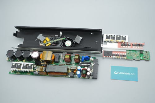
Remove the screws to detach the top and side covers of the module.

The fan is connected via a connector.

The PCBA module is fixed inside the housing with screws.

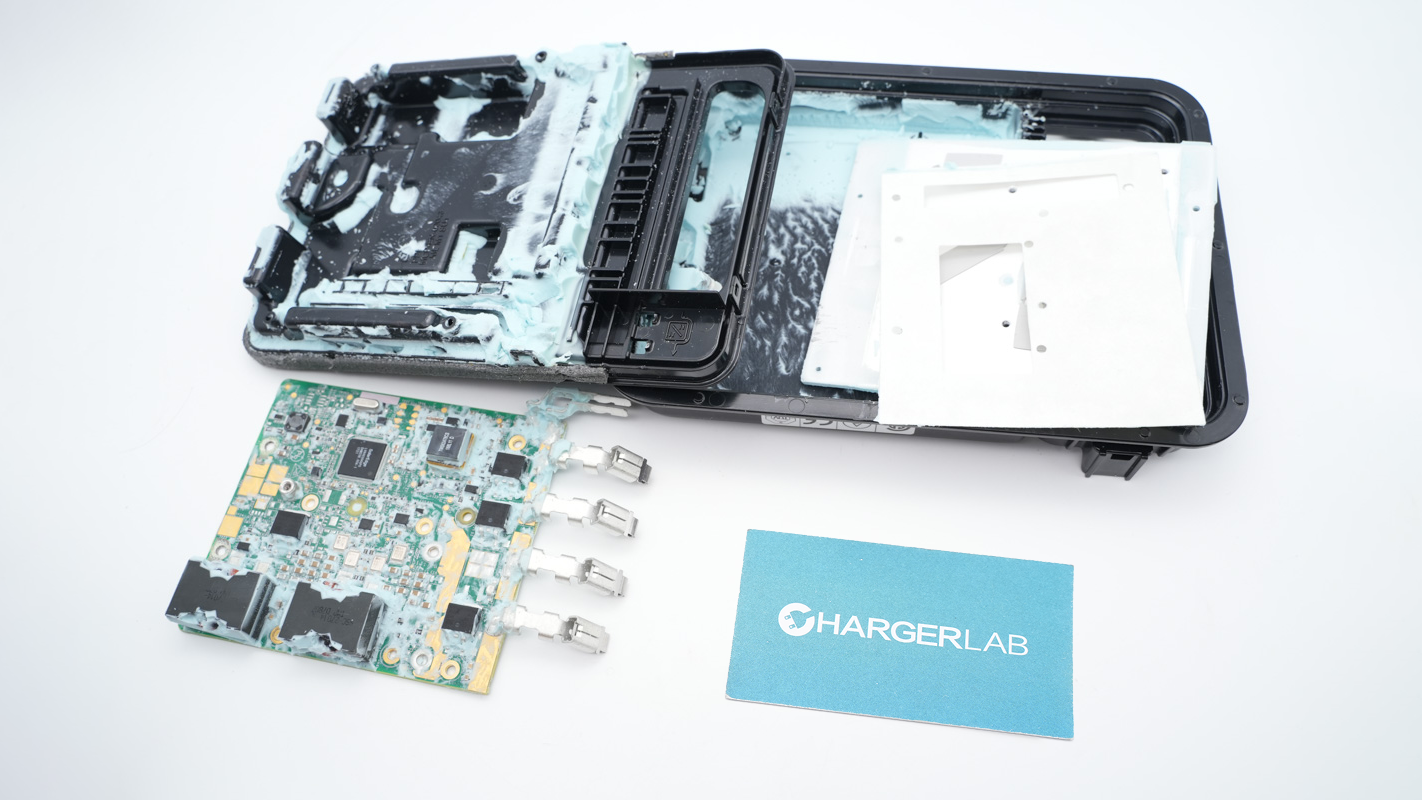
The interior of the top cover is lined with a Mylar sheet.

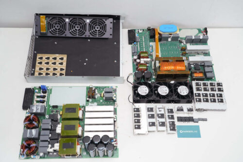
Remove the PCBA module, which is equipped with Mylar insulation at the bottom.

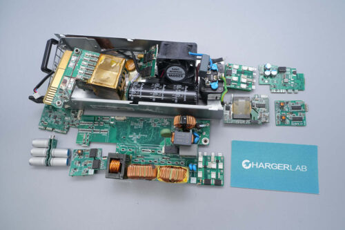
The front of the PCBA module contains safety X2 capacitors, fuses, varistors, common mode chokes, relays, startup resistors, a PFC inductor, high-voltage filtering capacitors, PFC MOSFETs, PFC rectifiers, and LLC MOSFETs.

The rear side, at the center, features a standby power supply IC, op-amps, and drivers.

Remove certain components and the control PCB.

The input safety X2 capacitor is from Faratronic, with a specification of 2.2μF.

The fuses at the input end are insulated with heat shrink tubing.

The blue Y capacitor is from MURATA, with part number 471K.

The other Y capacitor has the same model number.

The gas discharge tube is insulated with heat-shrink tubing.

The varistors are insulated with heat shrink tubing.

The varistors are from TDK, marked with S20K385K1, and are used to absorb overvoltage surges.

The common mode choke is wound with enameled wire and is insulated at the bottom with bakelite.

The safety X2 capacitor has a specification of 1μF.

The other common mode choke is also wound with enameled wire and is insulated at the bottom with bakelite.

The safety X2 capacitor has a specification of 3.3μF.

The Y capacitors are soldered to the bottom of the X capacitors, sourced from Zhongxing, with a specification of 0.01μF.

The relay is from NEXEM, model EC2-12NU, with a coil voltage of 12V.

The other relay is model RB-112DF6, with a set of changeover contacts. The contact rating is 16A at 277VAC, and the coil voltage is 12V.

The two series-connected startup resistors have their leads insulated with plastic tubing.

The PFC inductor is wound with flat copper wire.

The PFC MOSFETs are secured to the heatsink with screws.

The PFC MOSFETs are from Oriental, model OSG65R125HF, NMOS type, with a voltage rating of 700V, a conduction resistance of 125mΩ, and a TO247 package. The leads are insulated with plastic tubing and are secured with glue.

The low-side driver is from TI, model UCC27524A. It is a dual-channel, 5A high-speed low-side gate driver with negative input voltage capability, and it comes in an SOIC8 package.

The other driver has the same model number.

The optocoupler is from Toshiba, model TLP715, with an SOP-6 package, used for driving signal isolation.

The other heatsink has a bridge rectifier and PFC rectifiers.

The bridge rectifier is from LRC, model D15SB80, with a specification of 800V, 15A, and comes in a D5 package.

The PFC rectifiers are from STMicro, model STPSC8H065D. They are SiC diodes with a specification of 650V, 8A, and high surge current capability. They come in a TO-220AC package.

The other bridge rectifier is model GBU15K, with a specification of 800V, 15A, and comes in a GBU package.

The isolation amplifier is from BROADCOM, model ACPL-C790-500E, used for current sensing isolation. It comes in an SO-8 package, with a current-sensing resistor located beneath it.、

The high-voltage filter capacitor is from NCC, part of the LXS series, with a 105°C heat resistance and a specification of 450V, 270μF.

The three filter capacitors are from RUC, part of the CD29C series, with a specification of 450V, 270μF.

The 10mΩ shunt resistor is used for current sensing.

The op-amp is from TI, model TL082I. It is a FET-input dual op-amp with a 30V operating voltage, and comes in an SOIC8 package.

The Onsemi LM2903 is a dual voltage comparator used for overcurrent detection, and it comes in an SOIC-8 package.

The other voltage comparator has the same model number.

The voltage regulator chip is from DIODES, marked with EH17A, model AZ1117H-5.0TRE1. It supports a 20V input voltage, with a 5V output and a 1A output current. It comes in an SOT223 package.

The LLC MOSFETs are secured to the heatsink with screws.

The LLC MOSFETs are from Oriental, model OSG65R038HZF, NMOS type, with a voltage rating of 700V, a conduction resistance of 38mΩ, and a TO247 package.

The half-bridge driver is from DIODES, model DGD21814. It is a 600V-rated half-bridge driver that supports MOSFET and IGBT applications, with drive currents of 1.9A/2.3A. It comes in an SO-14 package.

The other driver has the same model number.

The three resonant capacitors are from Zhongxing, with a specification of 1000V, 0.022μF, and are connected in parallel.

The resonant inductor is wound with Litz wire.

The transformer coils are insulated with high-temperature adhesive tape.

The two film capacitors are from Zhongxing, with a specification of 0.18μF.

The bottom of the transformer is equipped with MLCCs.

The synchronous rectifiers are fixed to the heatsink.

The synchronous rectifiers are from Onsemi, model FDP075N15A, NMOS type, with a voltage rating of 150V, a conduction resistance of 7.5mΩ, and a TO-220 package.

The filter inductor is wound with copper strip.

The filter capacitor is from Nichicon, part of the UBT series, known for high reliability and long lifespan. It is a high-temperature 125°C rated electrolytic capacitor with a lifespan of 10,000 hours, and has a specification of 470μF, 63V.

The filter inductor is wound with enameled wire.

The filter capacitor is from Elite, with a specification of 470μF, 63V.

The two film capacitors are from Zhongxing, with a specification of 0.18μF.

The standby power supply IC is from TI, marked with 28C45, model UCC28C45. It is a low-power current-mode controller, supporting a switching frequency of 1MHz, and comes in an SOIC-8 package.

The auxiliary power MOSFET is insulated with adhesive tape.

The auxiliary power supply MOSFET is from Vishay, model IRFBF20, an N-channel device rated at 900 V with an RDS(on) of 8 Ω, packaged in TO-220AB.

Close-up of the auxiliary power supply transformer.

Close-up of the output rectifiers.

Close-up of the other two rectifiers.

Close-up of the MLCCs.

The front side of the control PCB features an op-amp, optocouplers, an isolation amplifier, memory, a controller IC, and voltage regulator ICs.

The rear side houses a CAN transceiver and two voltage regulator ICs.

The controller is from TI, model TMS320F28033, integrating a C2000 32-bit MCU running at 60 MHz, with 64 KB Flash and 20 KB RAM, packaged in TQFP64.

Close-up of the 20.000 MHz crystal oscillator.

The memory is from Microchip Technology, model 24LC16B, with a capacity of 16 KB, packaged in SOIC8.

The op-amp is from TI, model LM2904AV, a standard dual op-amp supporting a 3–30 V operating voltage range, packaged in SOIC8.

Two LM2904AV dual op-amps are located on the left side of the small PCB.

The other op-amp is the same model.

The optocouplers are from LITEON, model LTV816, sealed and insulated with potting compound.

The isolated voltage sensor is from Broadcom, model ACPL-C87H-500E, featuring high common-mode transient immunity, packaged in SO-8.

The isolated optocoupler is from LITEON, model 6N136, offering excellent AC and DC isolation capability, packaged in SOP-8.

The isolated CAN transceiver is from NOVOSENSE, model NSi1050, compliant with the ISO11898-2 standard, supporting 5 kVrms isolation voltage and a data rate of 1 Mbps, packaged in SOW16.

The voltage regulator IC is from Diodes Incorporated, model AZ1117D-3.3E1, supporting up to 20 V input, with a 3.3 V output and 1 A output current, packaged in TO-252-2.

The voltage regulator IC is from DIODES, model AZ1117H-5.0TRE1.

The other voltage regulator IC is the same model.

Close-up of the signal transmission isolation transformer.

A filter inductor is positioned between the high-voltage capacitors.

Close-up of the connector for the cooling fan.

Three LED indicators are mounted on the vertical PCB.

The rear side is reinforced with adhesive potting compound.

A temperature sensor is located on the front side of this small PCB.

There are two capacitors on the rear side.

The filter capacitors are from NCC, rated at 16 V, 220 μF.

The cooling fan is from PROTECHNIC, model MGT4028WB-W28, rated at 12 V, 1.2 A, and equipped with stationary blades.

Well, those are all components of the VERTIV 3500W SiC Rectifier Module.
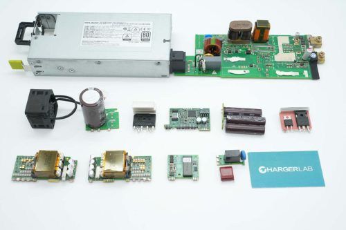
Summary of ChargerLAB

Here is the component list of the VERTIV 3500W SiC Rectifier Module for your convenience.
The module model is R48-3500e3, supporting an input voltage range of 200–277 Vac and delivering a -48 V DC output with a rated power of 3500 W. The AC input and DC output connectors are integrated into a single assembly.
After taking it apart, we found that it uses a TI control solution, with the TMS320F28033 for system control, and implements a bidirectional switch-bridgeless PFC + full-bridge LLC + synchronous rectification topology. The PFC MOSFETs and LLC MOSFETs are from Oriental, the PFC rectifiers use SiC diodes from STMicro, and the synchronous rectifiers are from Onsemi.
The PFC MOSFETs and LLC MOSFETs use gate drivers from TI and Diodes, respectively. The isolated current- and voltage-sensing ICs are from BROADCOM. The PCBA module is coated with conformal coating on both sides for protection, components are reinforced with adhesive, the MOSFETs' leads are fitted with insulating sleeves and secured with adhesive, and the build quality and material selection are robust.
Related Articles:
1. Teardown of EcoFlow 240W USB4 Fast Charging Braided Cable
2. Teardown of VERYSUN 100W GaN Charger (X100Pro)
3. Teardown of Lenovo thinkplus FLUXO 150W GaN Desktop Charging Station (CSFO150A4)