Introduction
In this teardown, we’ll be examining the Supermicro 720W redundant power supply module, model PWS-721P-1R. This unit utilizes a PFC + phase-shift full-bridge topology and is certified for 80 PLUS Gold efficiency. It supports a wide input voltage range of 100–240V AC and provides a 12V main output along with a 5V standby rail.
The power supply is housed in a long, rectangular metal enclosure. On the input side, it features a cooling fan, handle, status indicator LED, and a standard C14 AC inlet. The output side uses a gold finger edge connector for power delivery in redundant server configurations. Now, let’s take a look inside this power supply to examine its design and components.
Product Appearance
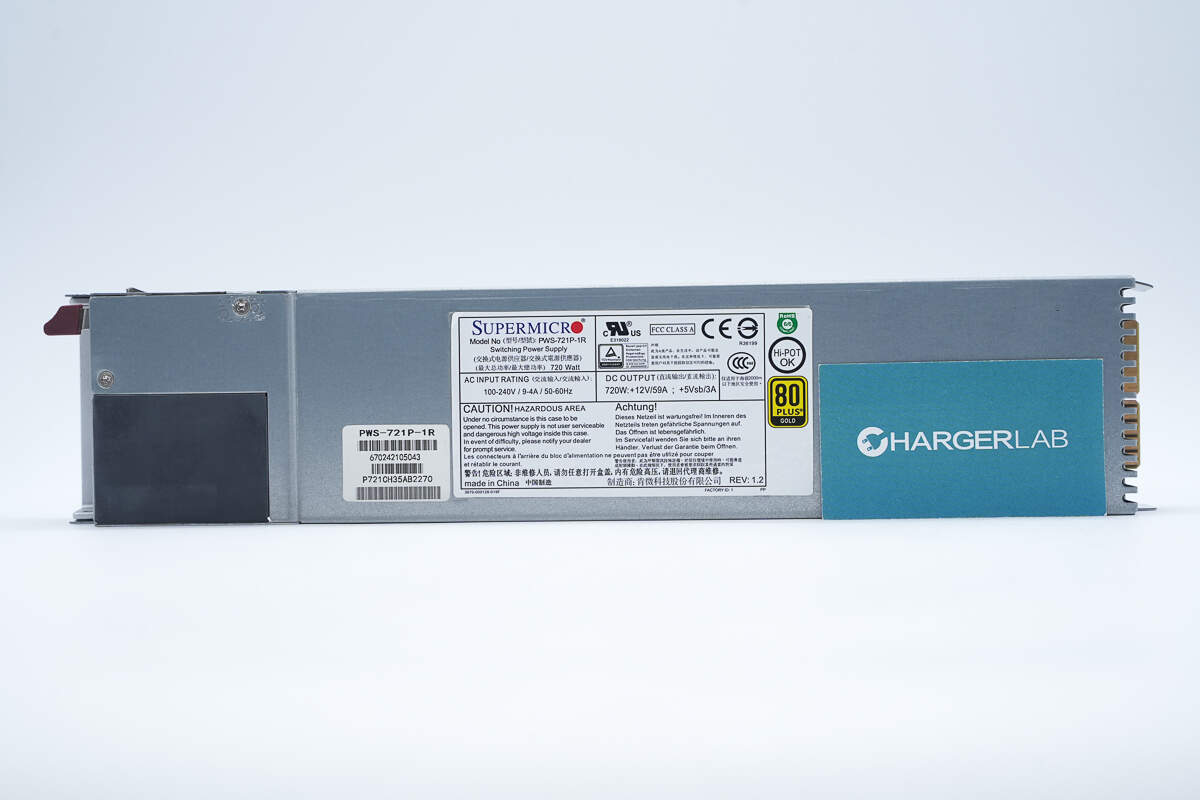
The metal enclosure is secured with screws.
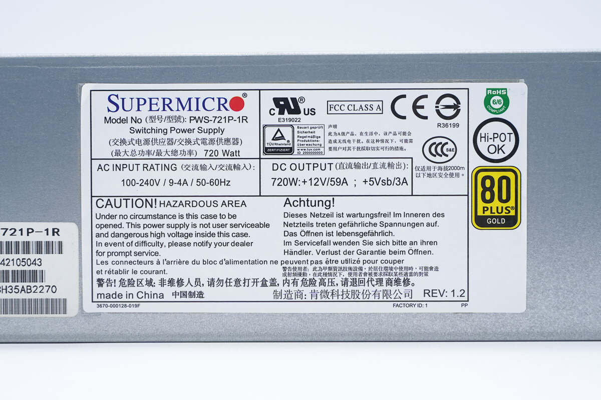
Model: PWS-721P-1R
Maximum Total Power: 720W
AC Input: 100–240V / 9–4A / 50–60Hz
DC Output: 720W: +12V / 59A; +5Vsb / 3A
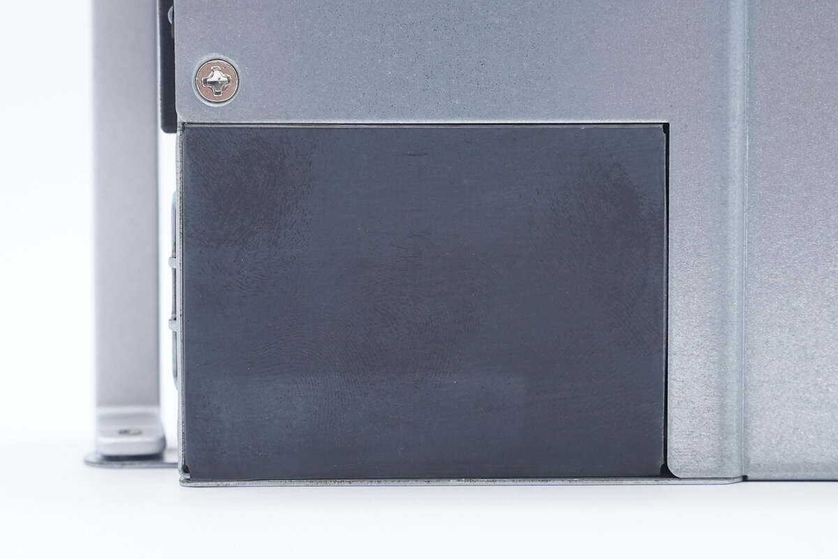
The cooling fan is covered with a Mylar film for protection.
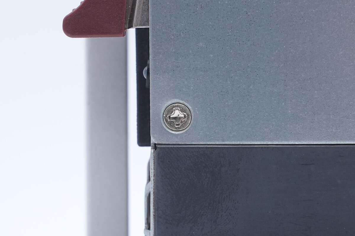
Close-up of the mounting screw.
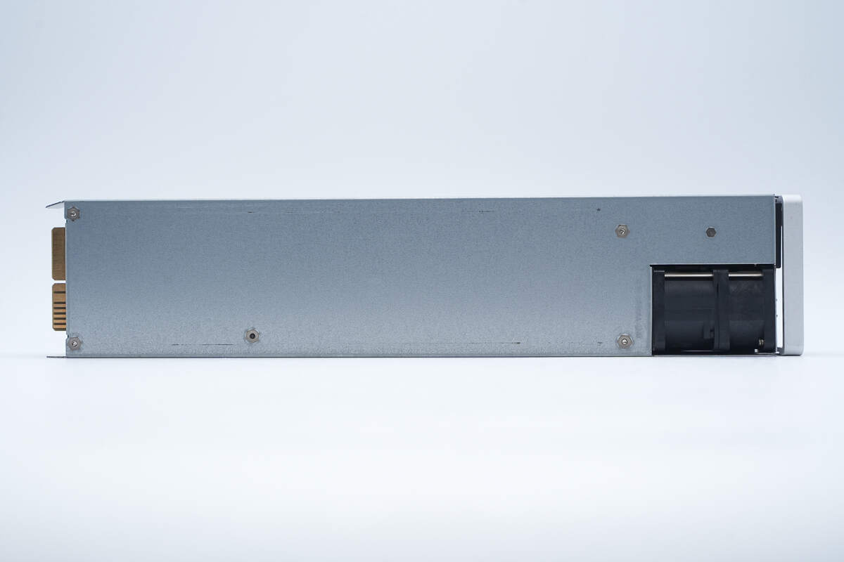
This side features mounting screw holes. The area corresponding to the fan is cut out to reduce overall thickness.
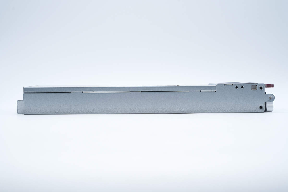
The side of the enclosure is secured with locking clips.
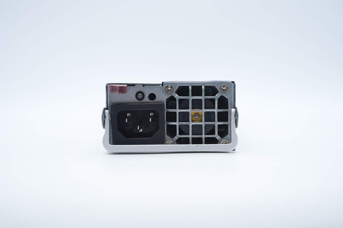
The input side features a C14 power inlet, a cooling fan, an LED indicator, and a handle.
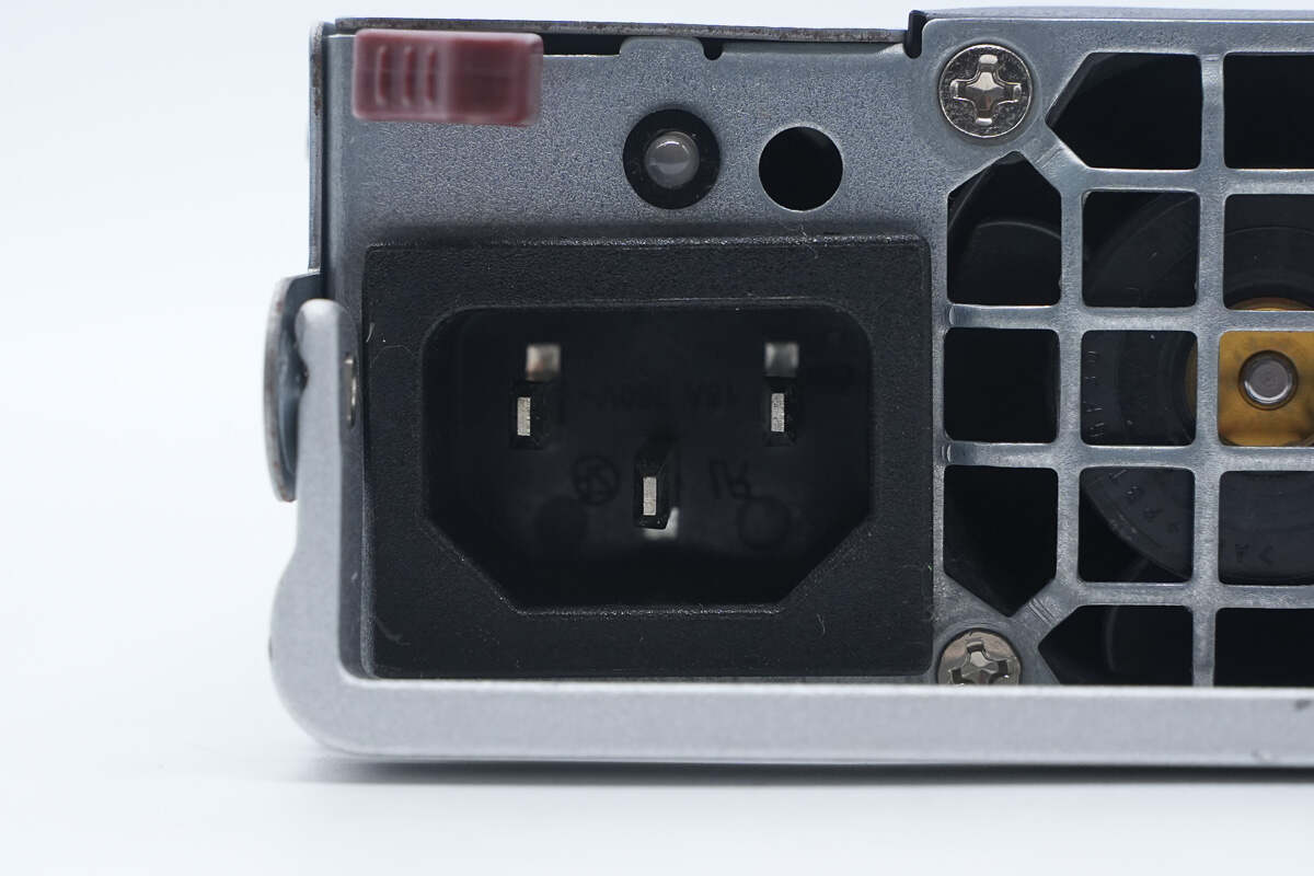
Above the C14 power inlet is the LED indicator.
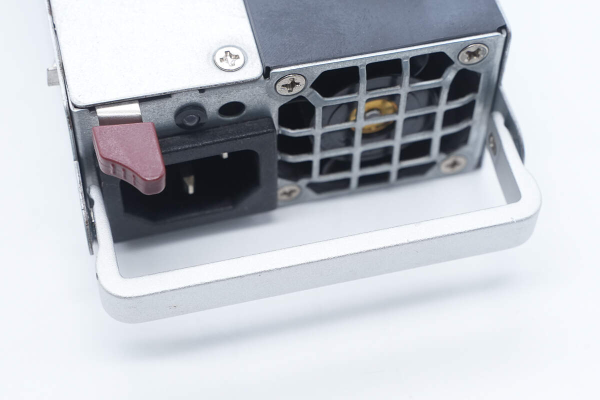
Close-up of the aluminum alloy handle.
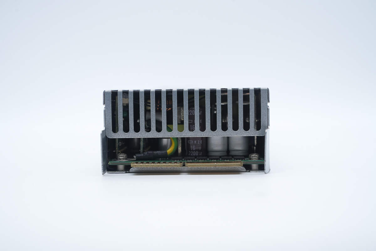
The output side features a protective grille and a gold finger connector.
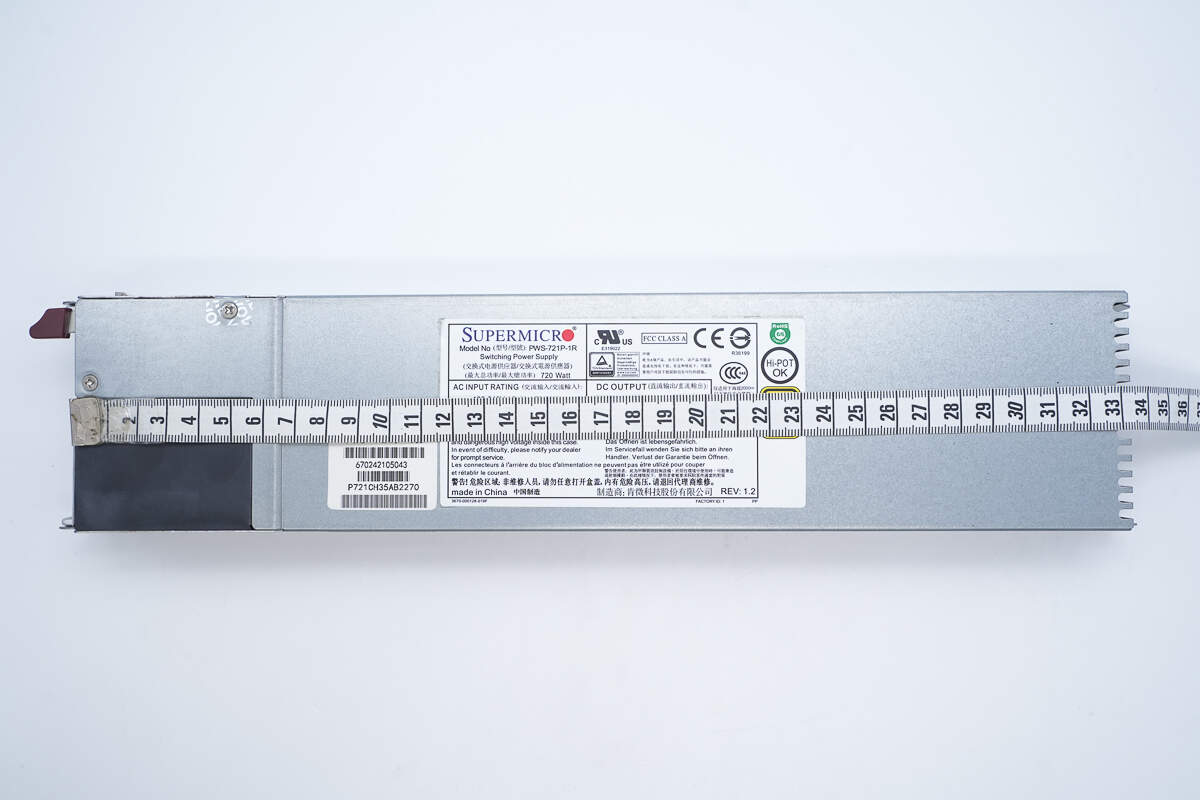
The length of the power supply is about 334 mm (13.15 inches).
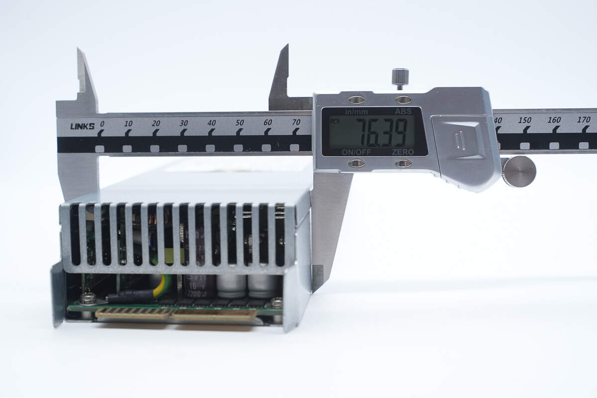
The width is about 76.4 mm (3.0079 inches).
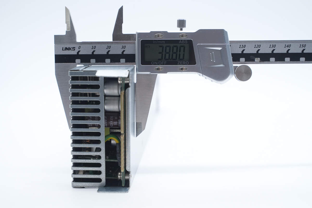
The thickness is about 38.8 mm (1.53 inches).
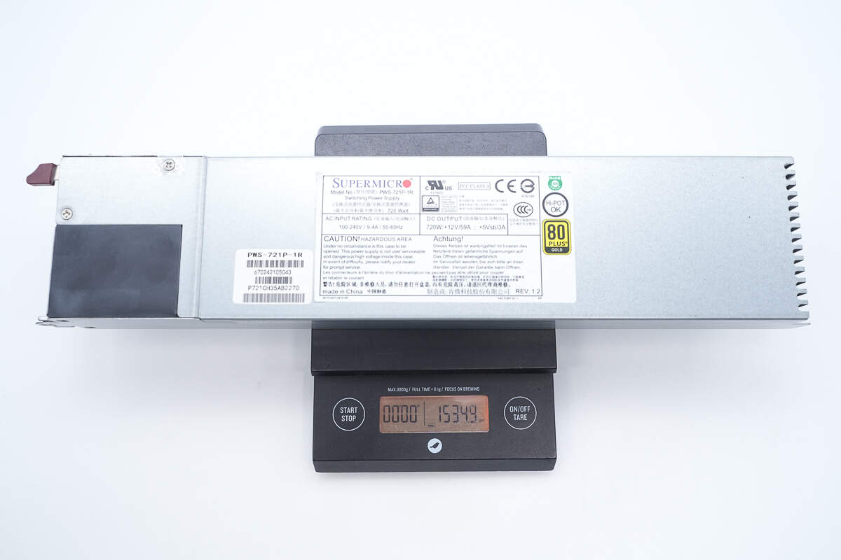
The weight is about 1535 g (54.15 oz).
Teardown
Next, let's take it apart to see its internal components and structure.
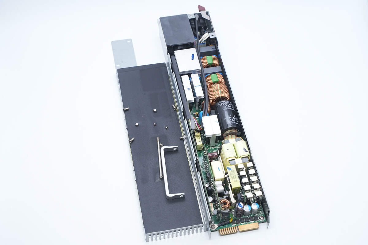
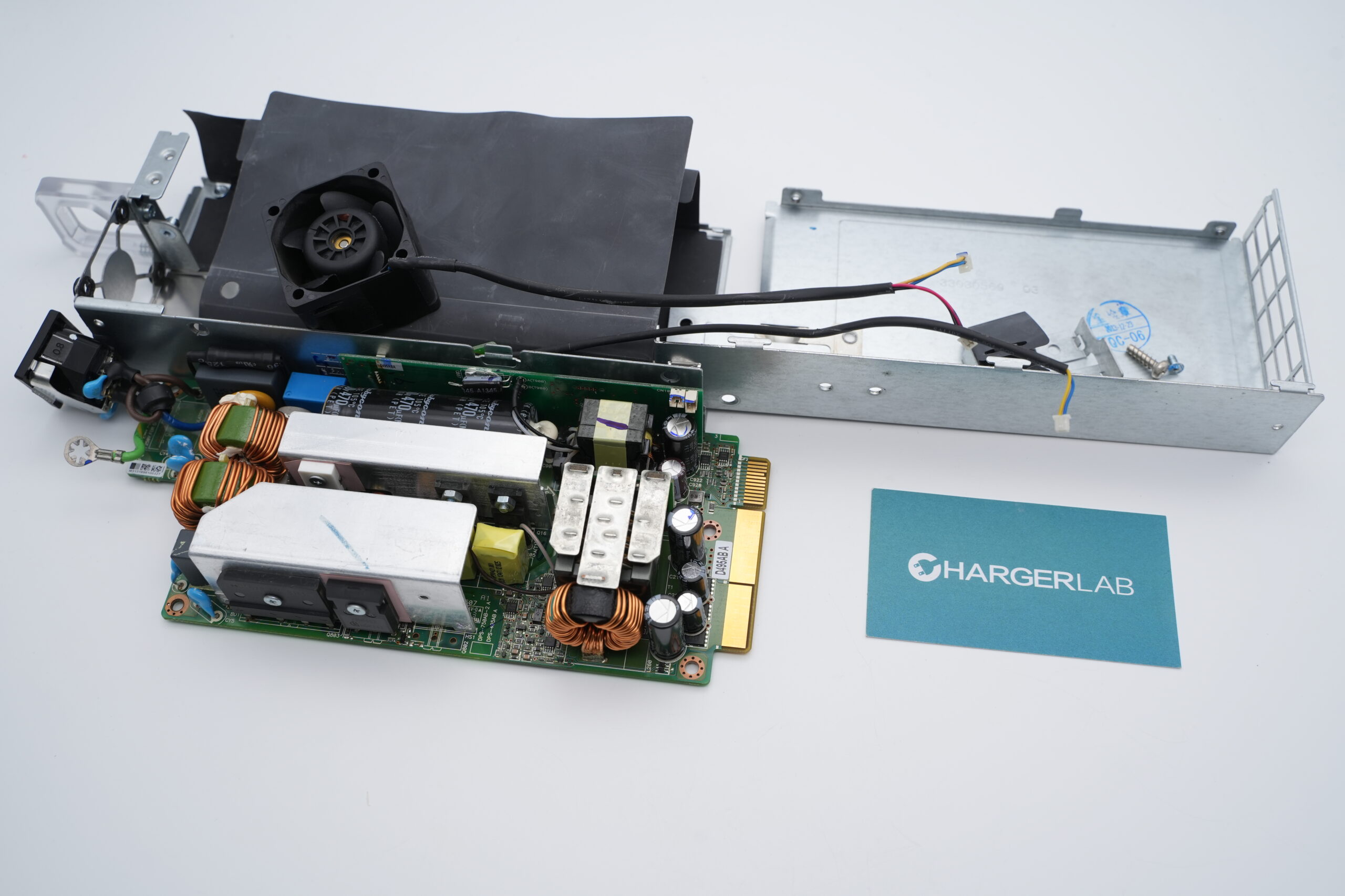
First, unscrew the mounting screws and remove the top cover. Inside, there is a black Mylar insulating sheet.
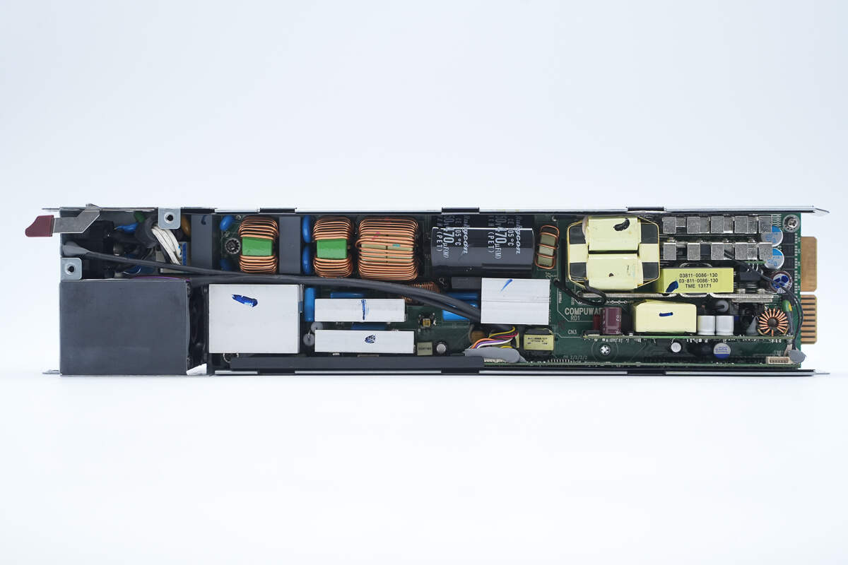
The PCBA module is fastened inside the enclosure using screws.
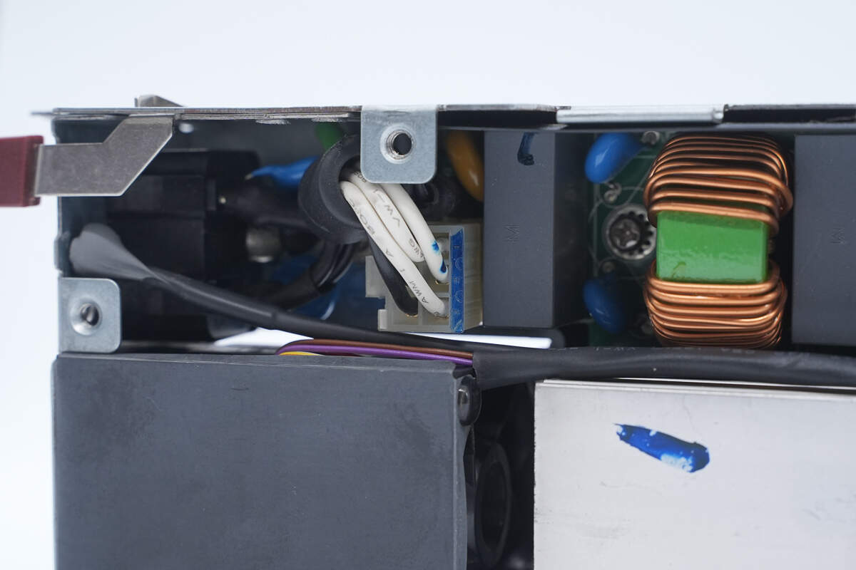
The AC input wires are connected via a plug-in connector.
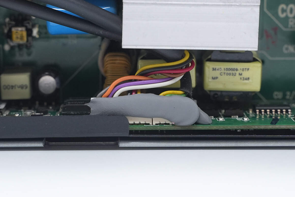
The fan and LED indicator are connected via plug-in connectors and sealed with adhesive for added stability.
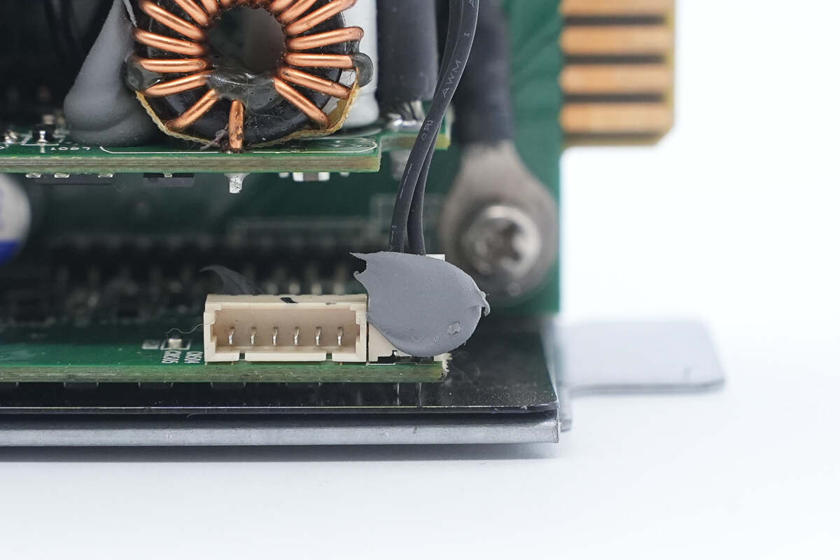
The thermistor is also connected via a plug-in connector.
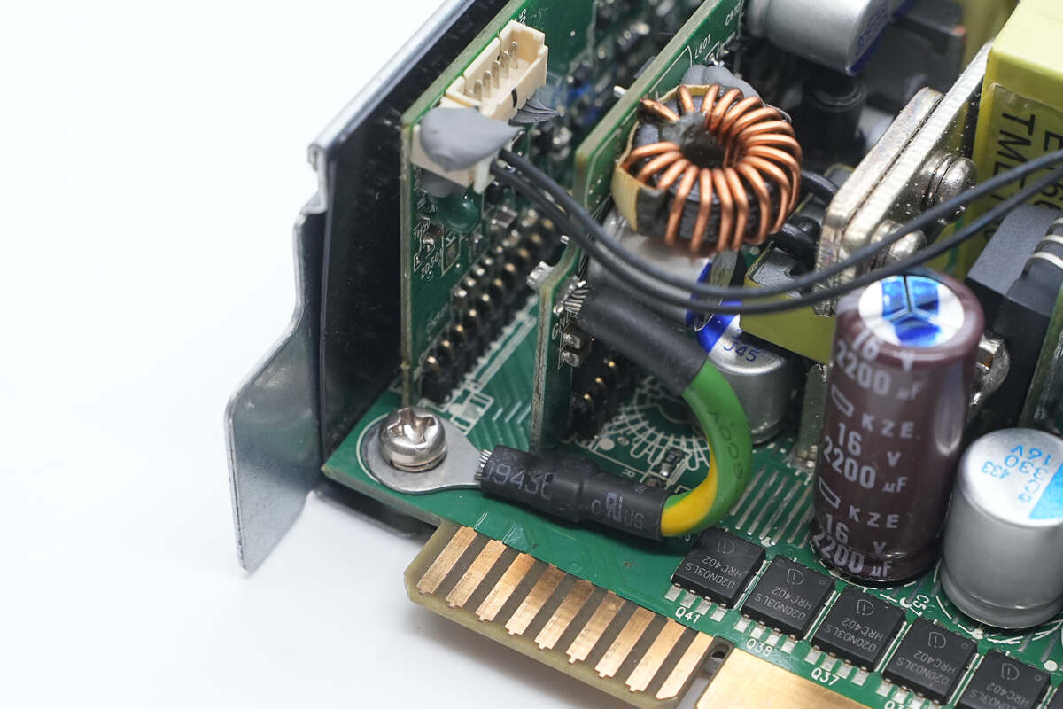
The grounding wire is secured with a screw.
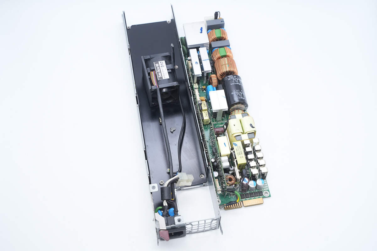
After removing the PCBA module, a black Mylar insulating sheet is found inside the enclosure.
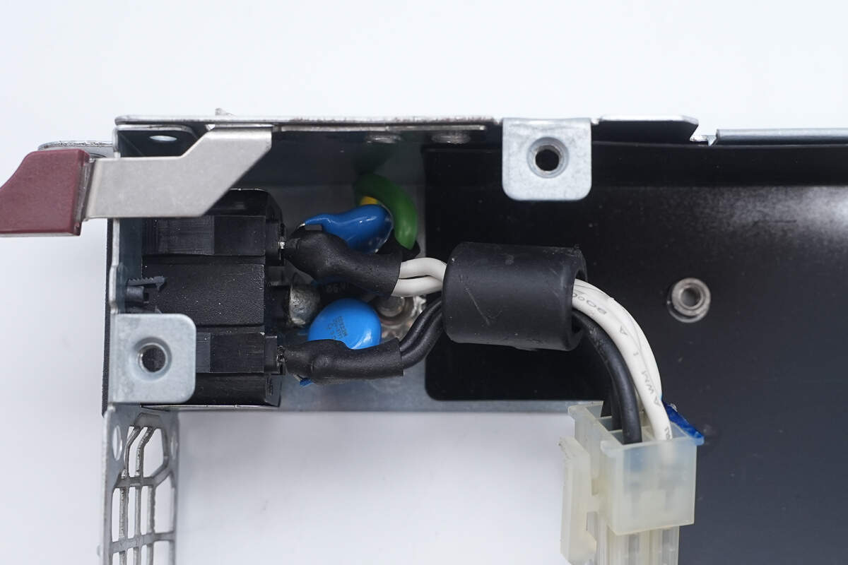
The power inlet is connected with soldered wires.
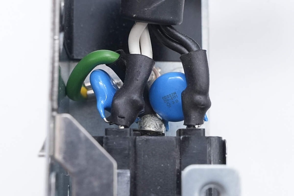
The power inlet is also soldered to a blue Y-capacitor. The solder joints on the wires are insulated with heat shrink tubing.
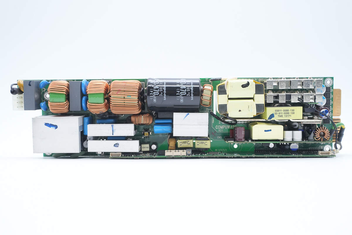
Overview of the PCBA module front side:
In the upper left corner are the connector socket, fuse, varistor, safety X2 capacitor, common-mode choke, and PFC inductor. Below them, the heatsink cools the bridge rectifier, PFC MOSFET, and PFC rectifier. Also present are a relay and a thermistor.
In the central upper area, there is the PFC boost inductor and high-voltage filter capacitors. Below that are the phase-shift full-bridge MOSFETs and the driver transformer. On the right side are the main transformer, synchronous rectifiers, and the standby power supply PCB. At the bottom is a long control PCB.
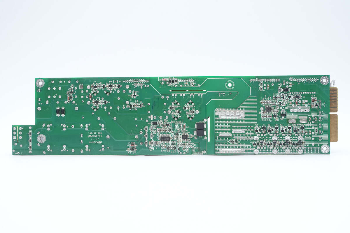
The back side of the PCBA module is soldered with voltage comparators, Op-Amps, fast recovery diodes, drivers, and a PWM controller.
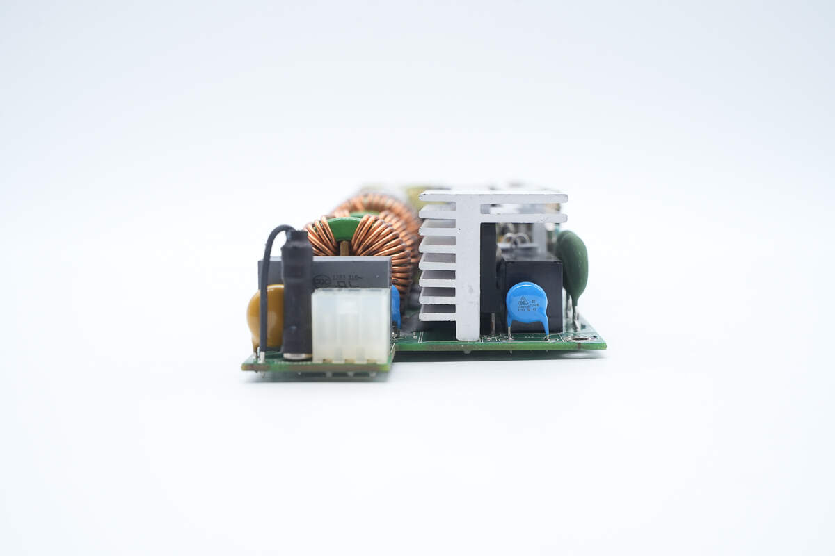
The input side includes a connector socket, fuse, varistor, safety-certified X2 capacitor, relay, Y-capacitor, and thermistor.
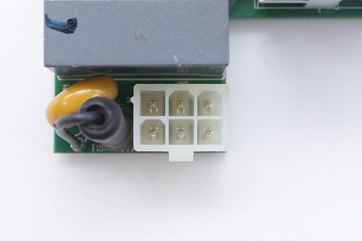
Close-up of the 6-pin AC input connector.
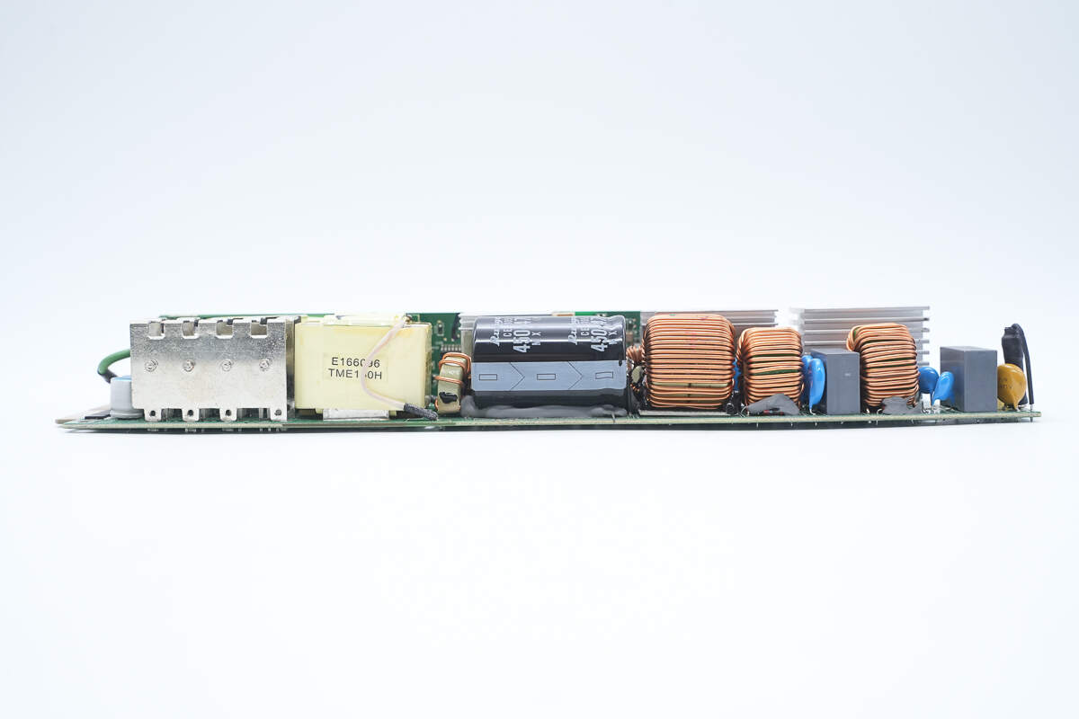
On the side of the PCBA module, there is a varistor, safety X2 capacitors, common-mode chokes, a PFC boost inductor, a high-voltage filter capacitor, a resonant inductor, and heatsinks for synchronous rectifiers and the transformer.
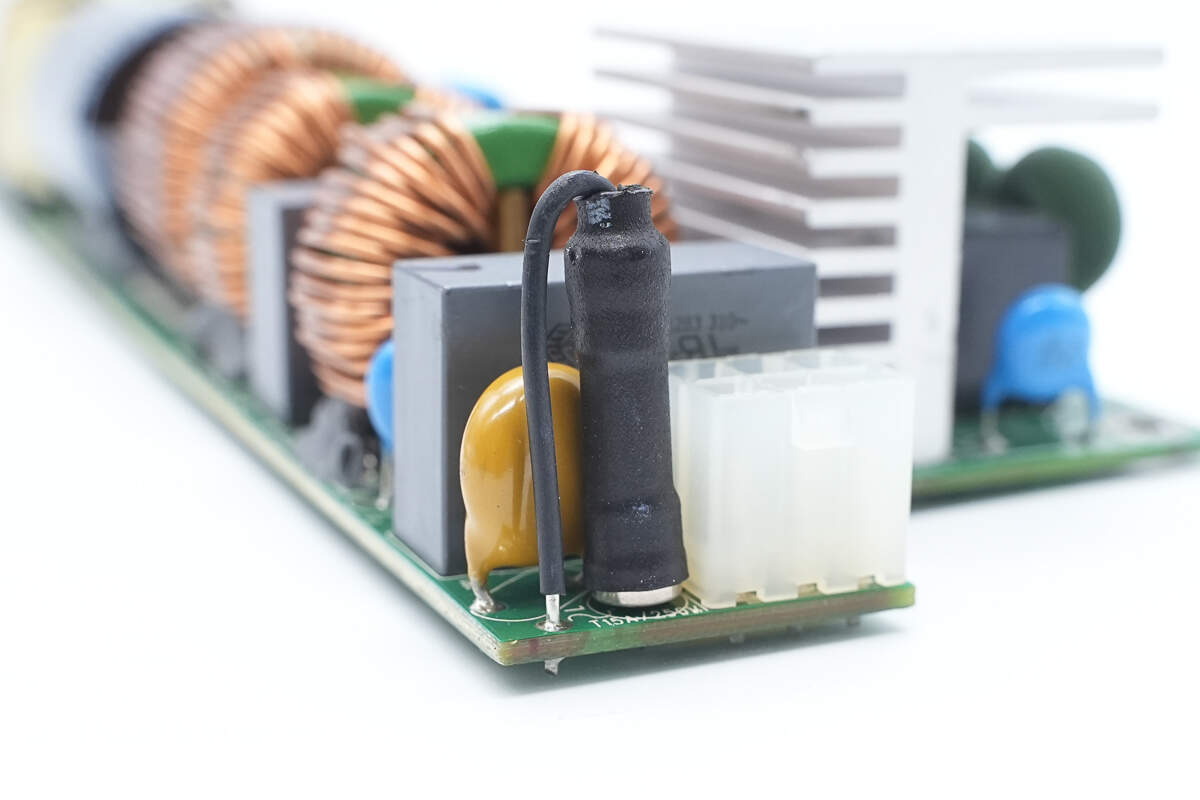
The fuse is insulated with heat-shrink tubing.

The varistor, marked TVR10471V, is used to absorb overvoltage surges.
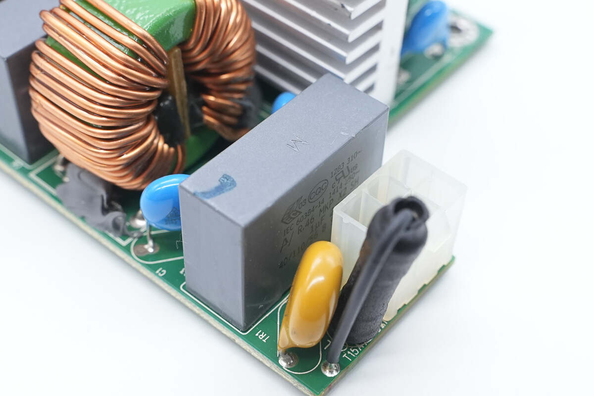
The safety X2 capacitor has a capacitance of 1 μF.
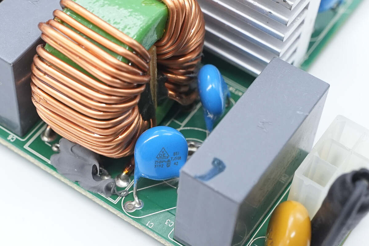
Close-up of the blue Y capacitor.
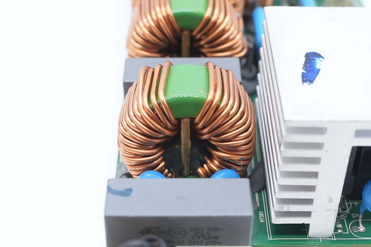
The common-mode choke is wound with enameled wire and features a Bakelite insulating board inside.
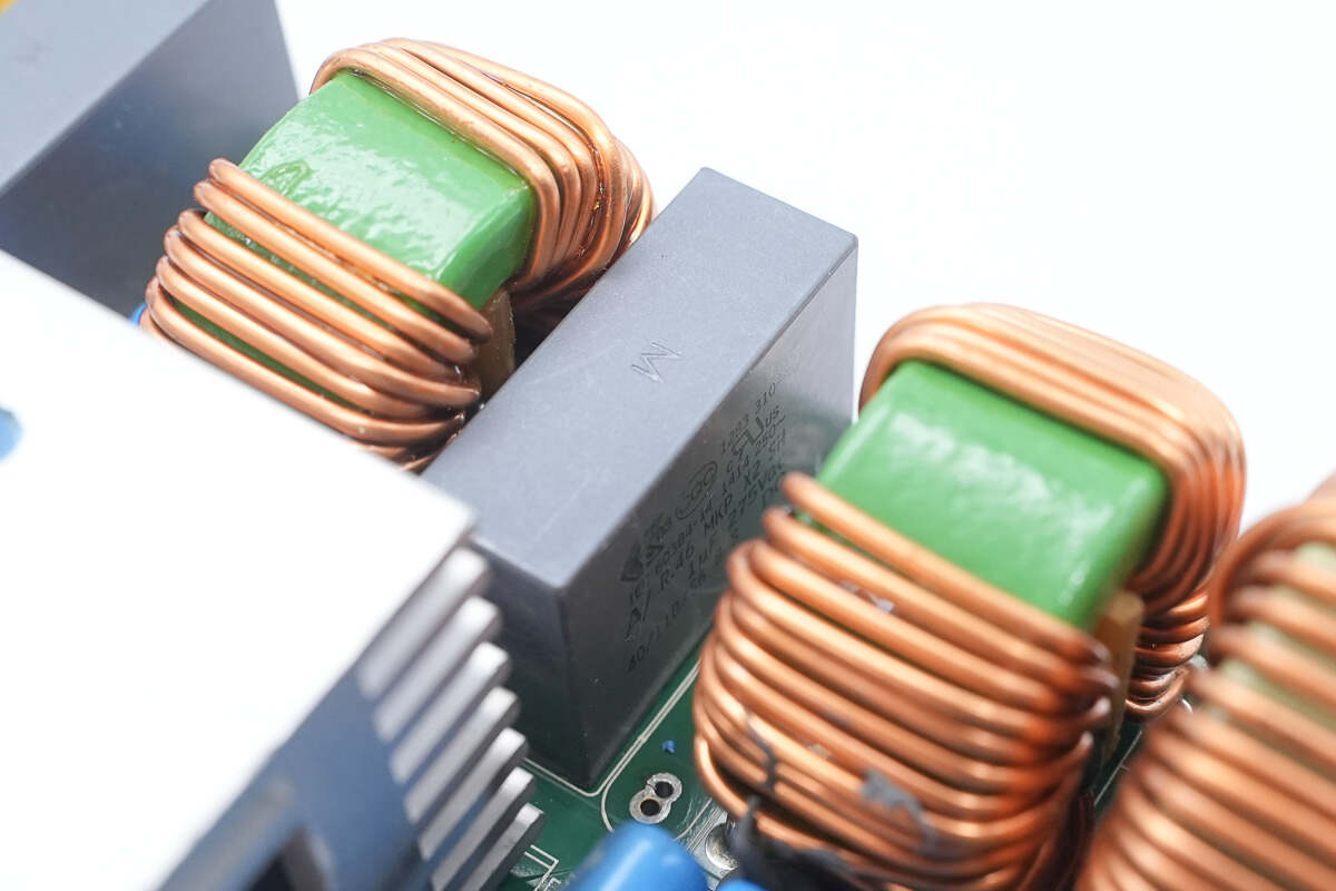
The other safety X2 capacitor has the same specifications.
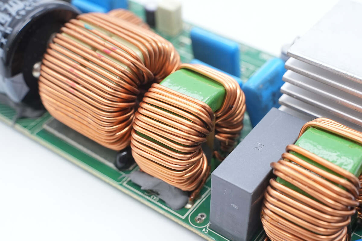
The common-mode choke is wound with enameled wire and internally insulated with a Bakelite board.
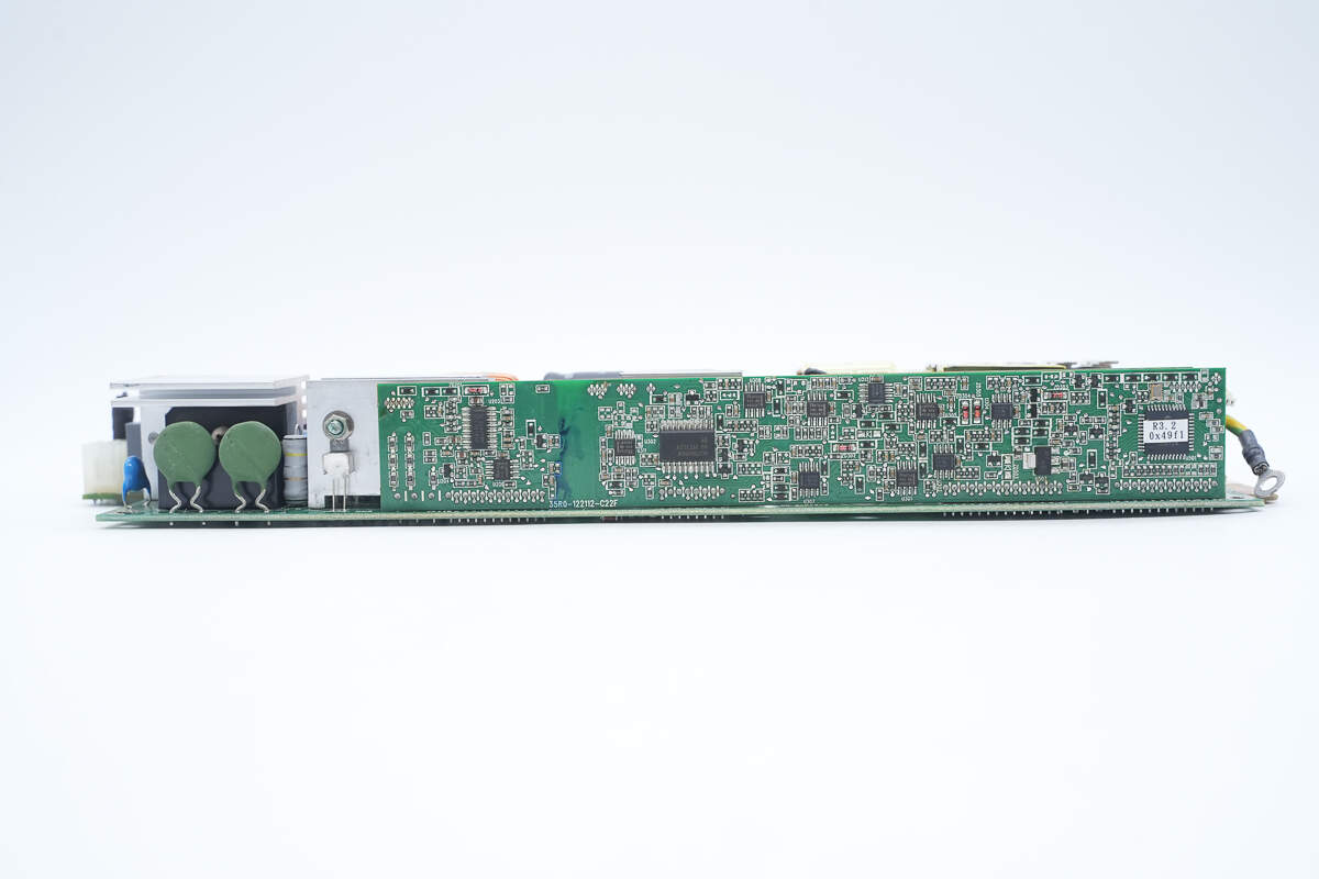
This side features a thermistor and a long, rectangular control PCB.
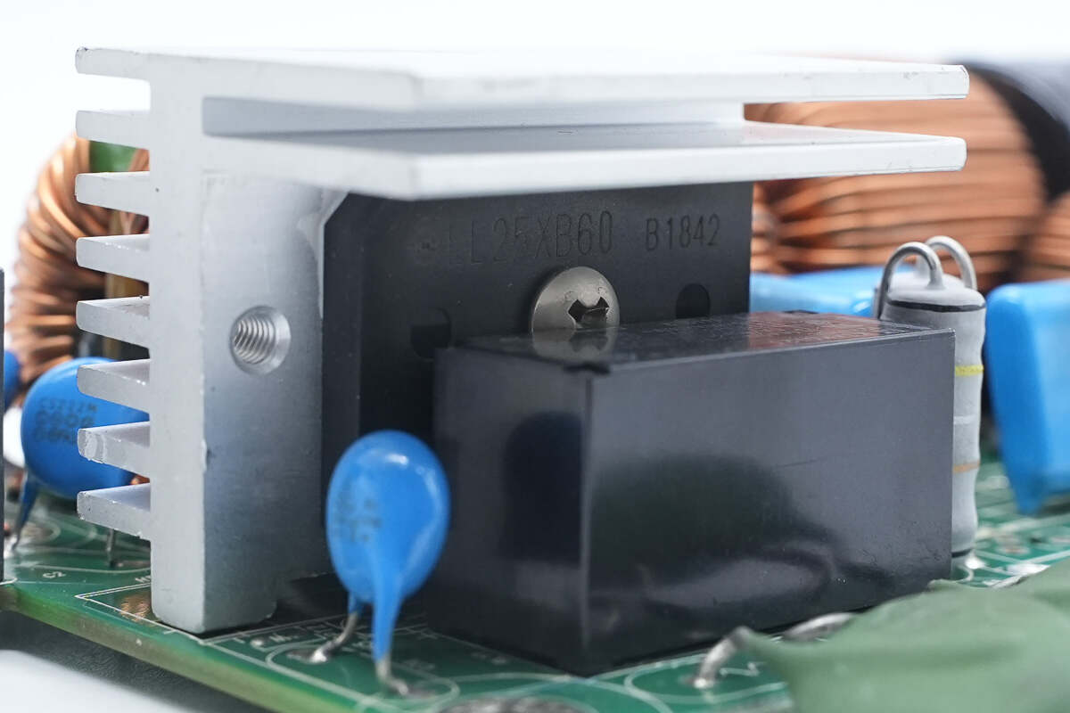
The bridge rectifier is from Shindengen, model LL25XB60, rated at 25A 600V, and uses a 5S package.
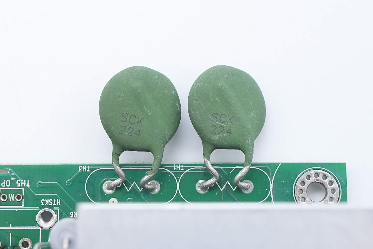
The thermistors, marked SCK224, are connected in series.
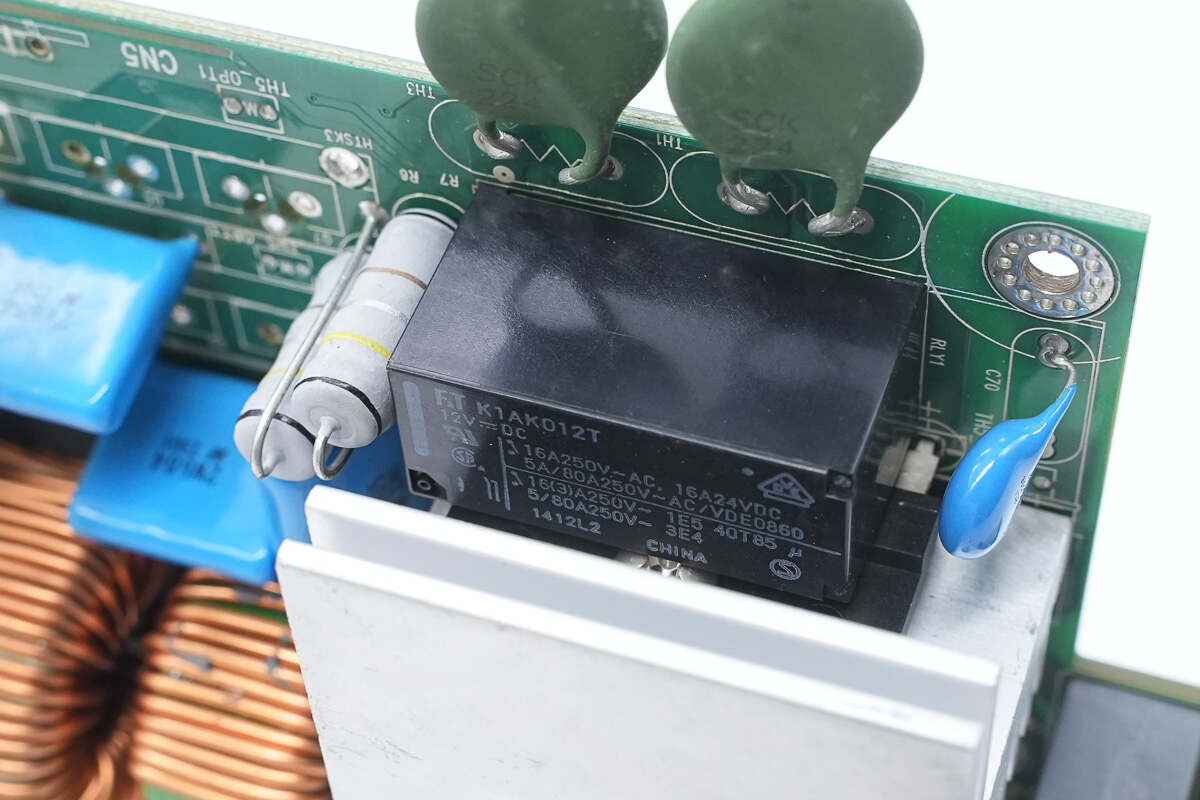
The relay is from Fujitsu, model FTR-K1AK012T. It features a single normally open contact with a contact rating of 16A at 250V, and a coil voltage of 12V.
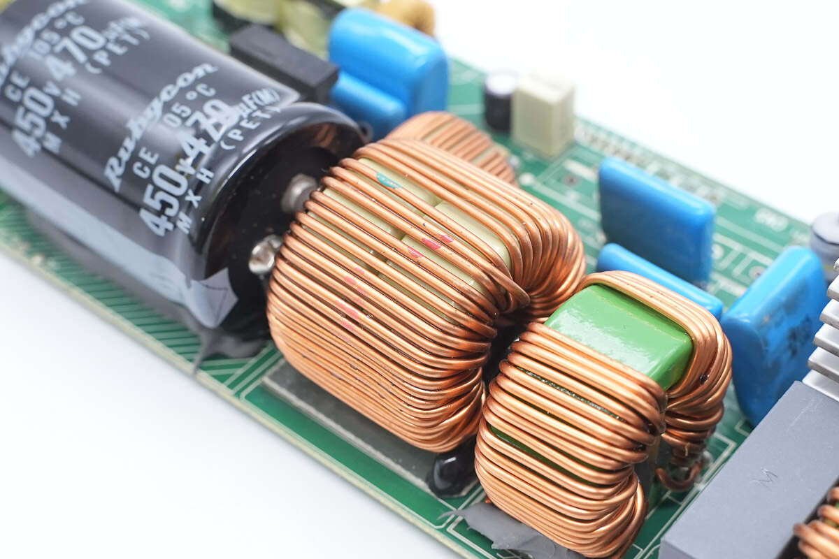
The PFC boost inductor is wound on a ferrite core.
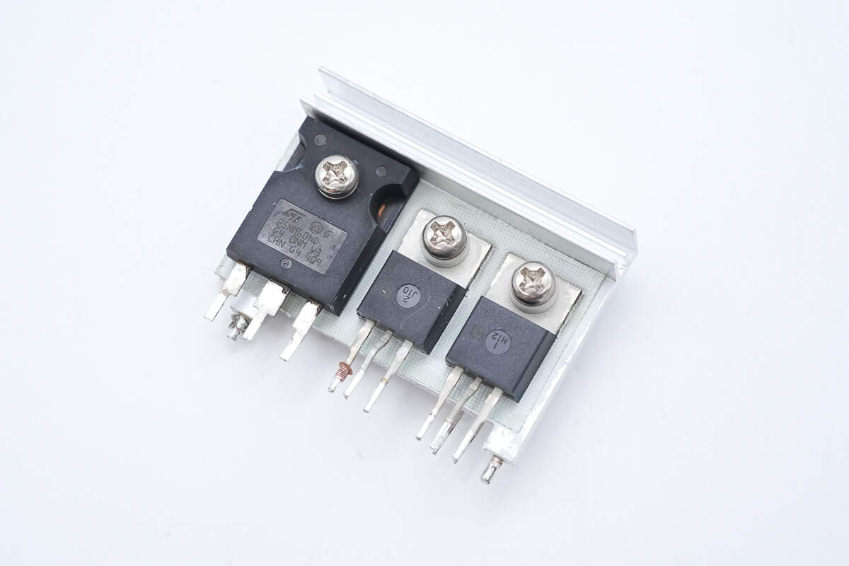
There are three MOSFETs mounted on the heatsink.
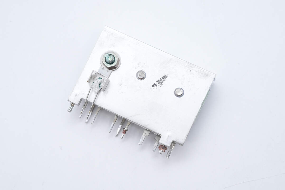
On the back, the thermistor is secured with a screw to monitor temperature.
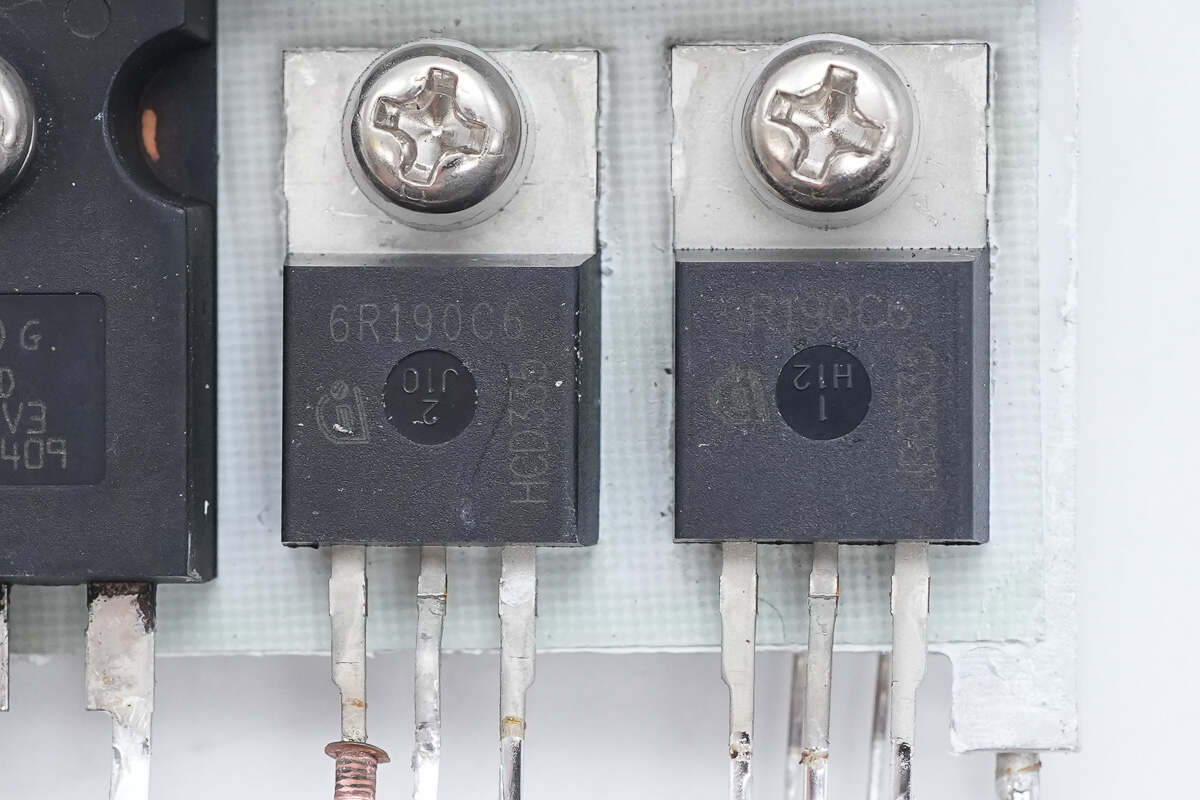
The PFC MOSFETs are from Infineon, model IPP60R190C6. They are N-channel MOSFETs with a voltage rating of 650V, an on-resistance of 190mΩ, and come in a TO-220 package.

Close-up of the thermistor mounted on the back of the heatsink.
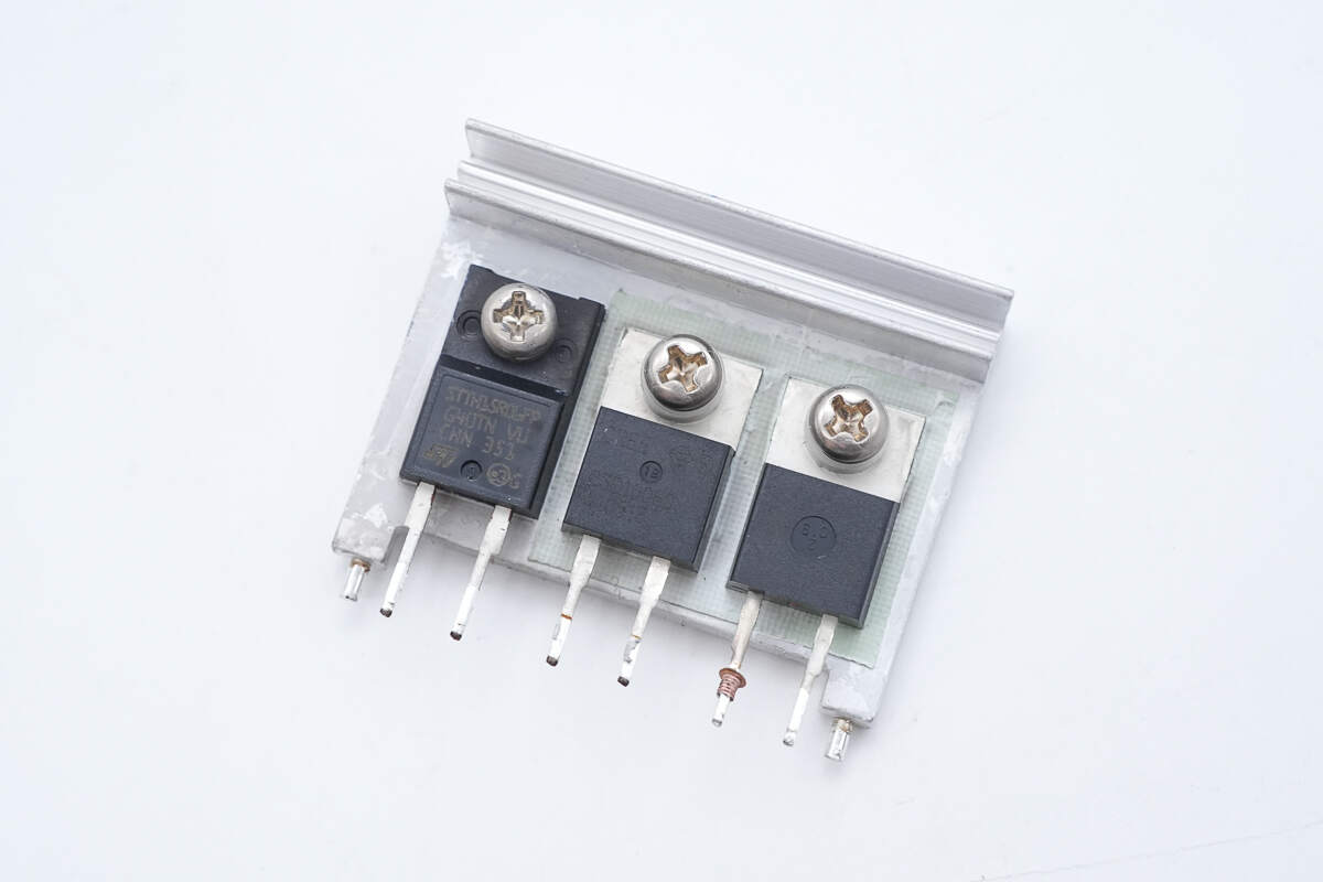
The other heatsink houses the rectifiers and PFC MOSFET.
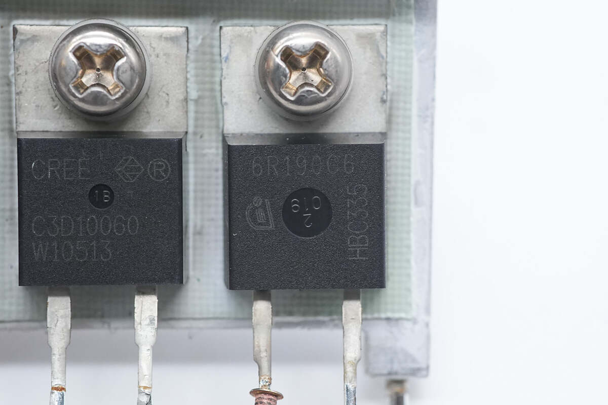
The PFC MOSFET is from Infineon, model IPP60R190C6, with a total of three units used.
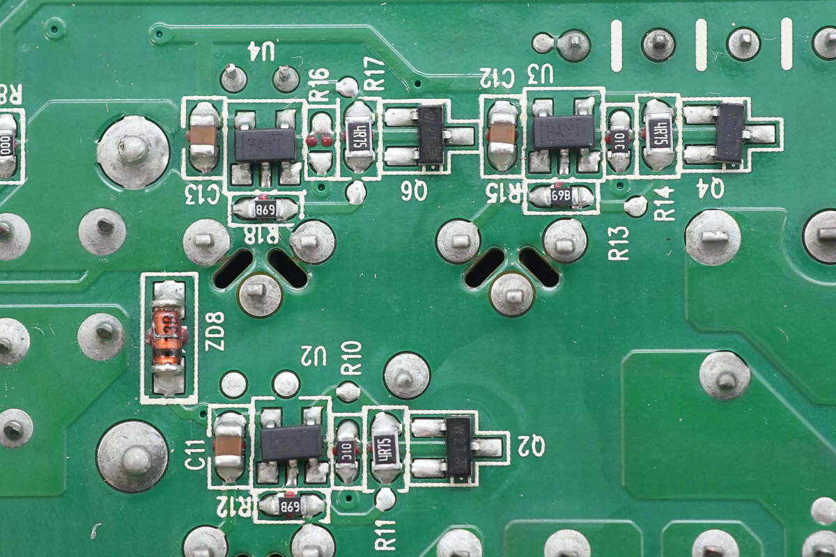
On the back side of the PCBA module, there are three driver ICs responsible for driving the PFC MOSFETs.
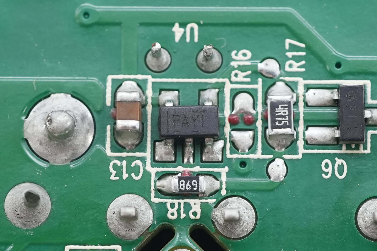
The drivers are from Texas Instruments, marked PAYI, model TPS2819. Each is a single-channel high-speed driver with a 2A output current, housed in a SOT-23 package.
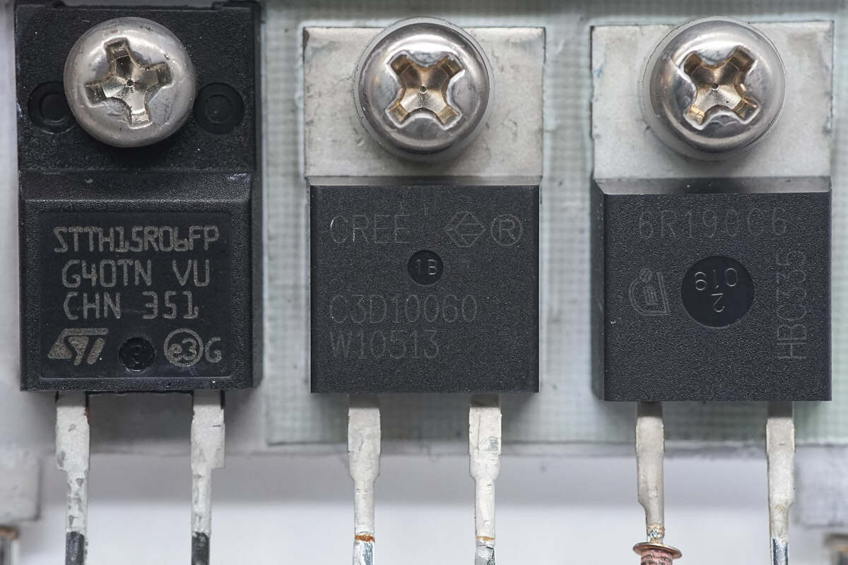
The PFC rectifier is from Wolfspeed, model C3D10060A. It is a third-generation SiC Schottky diode, rated at 600V and 10A, housed in a TO-220-2 package.
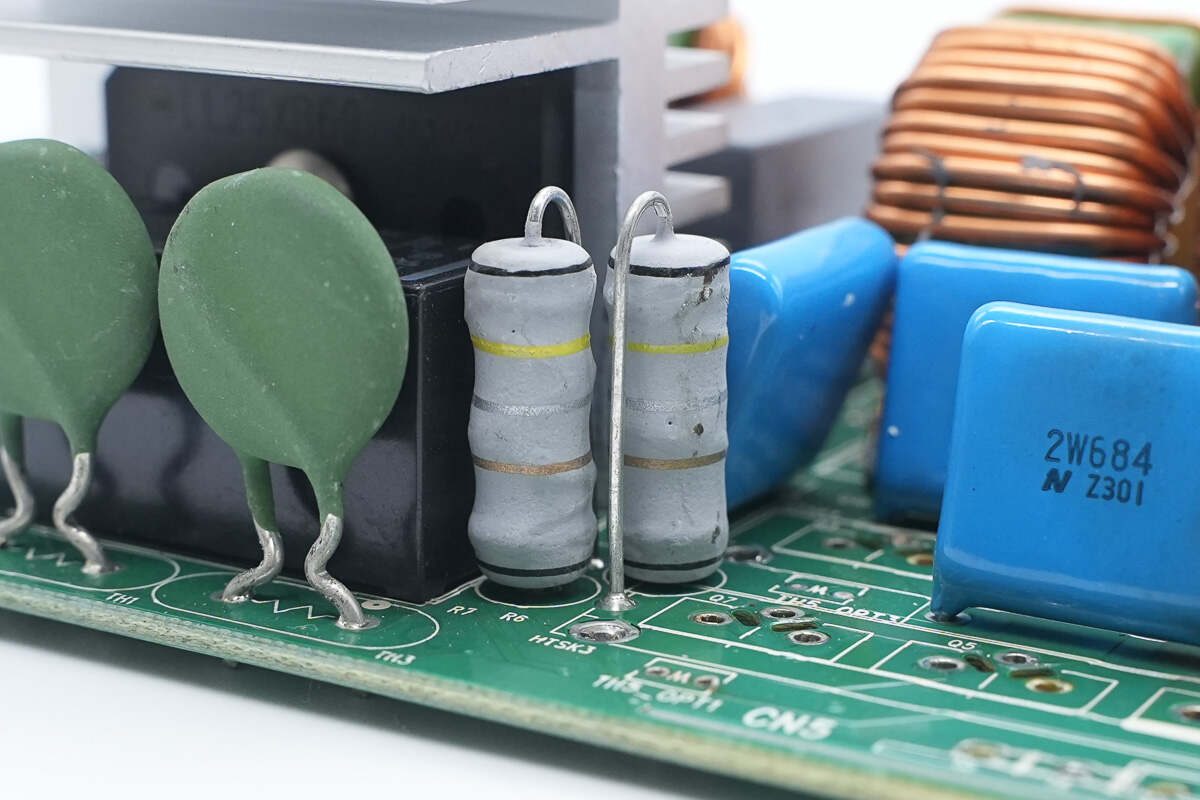
Two resistors are used to sense the current of the PFC MOSFETs.
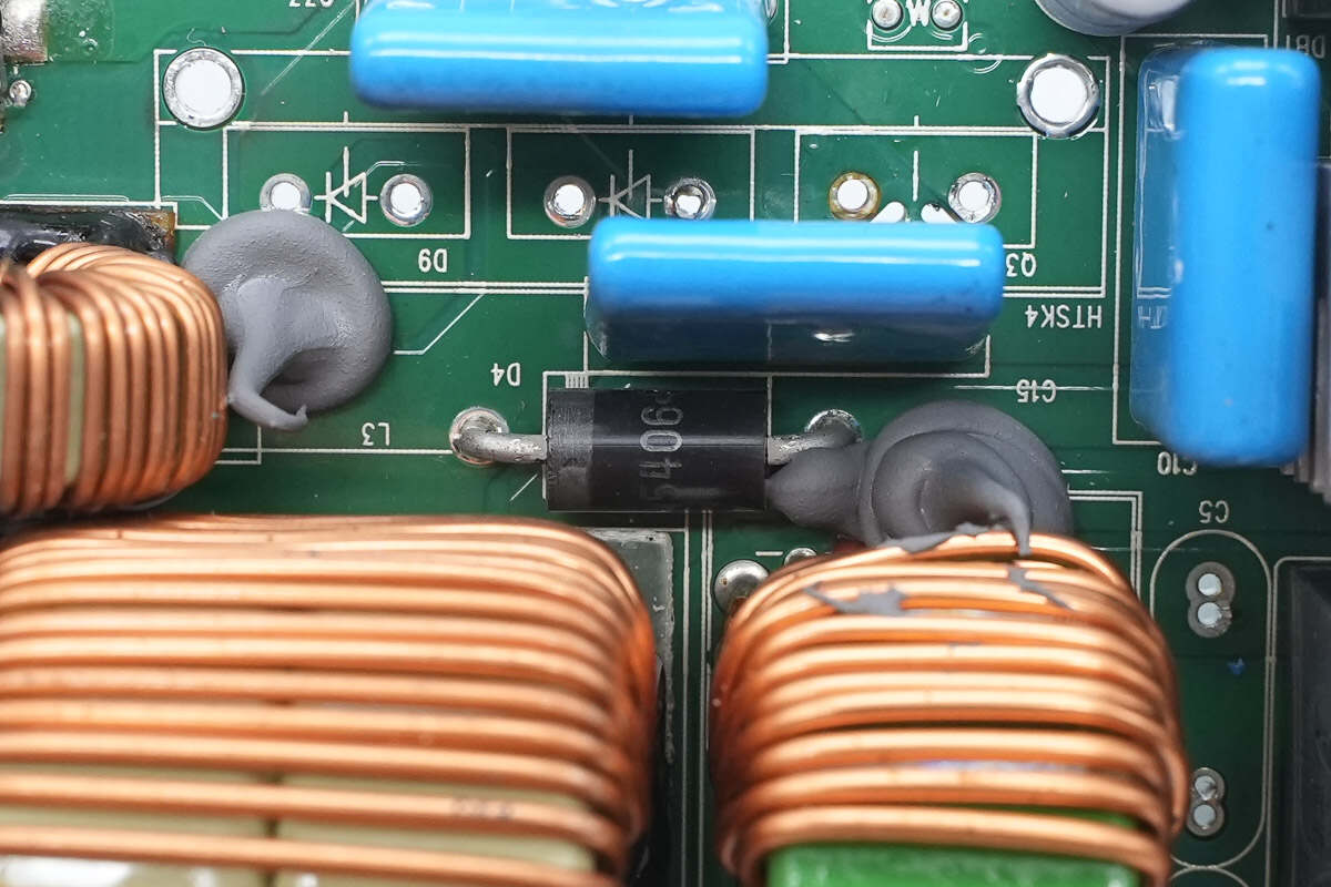
Close-up of the PFC bypass diode.
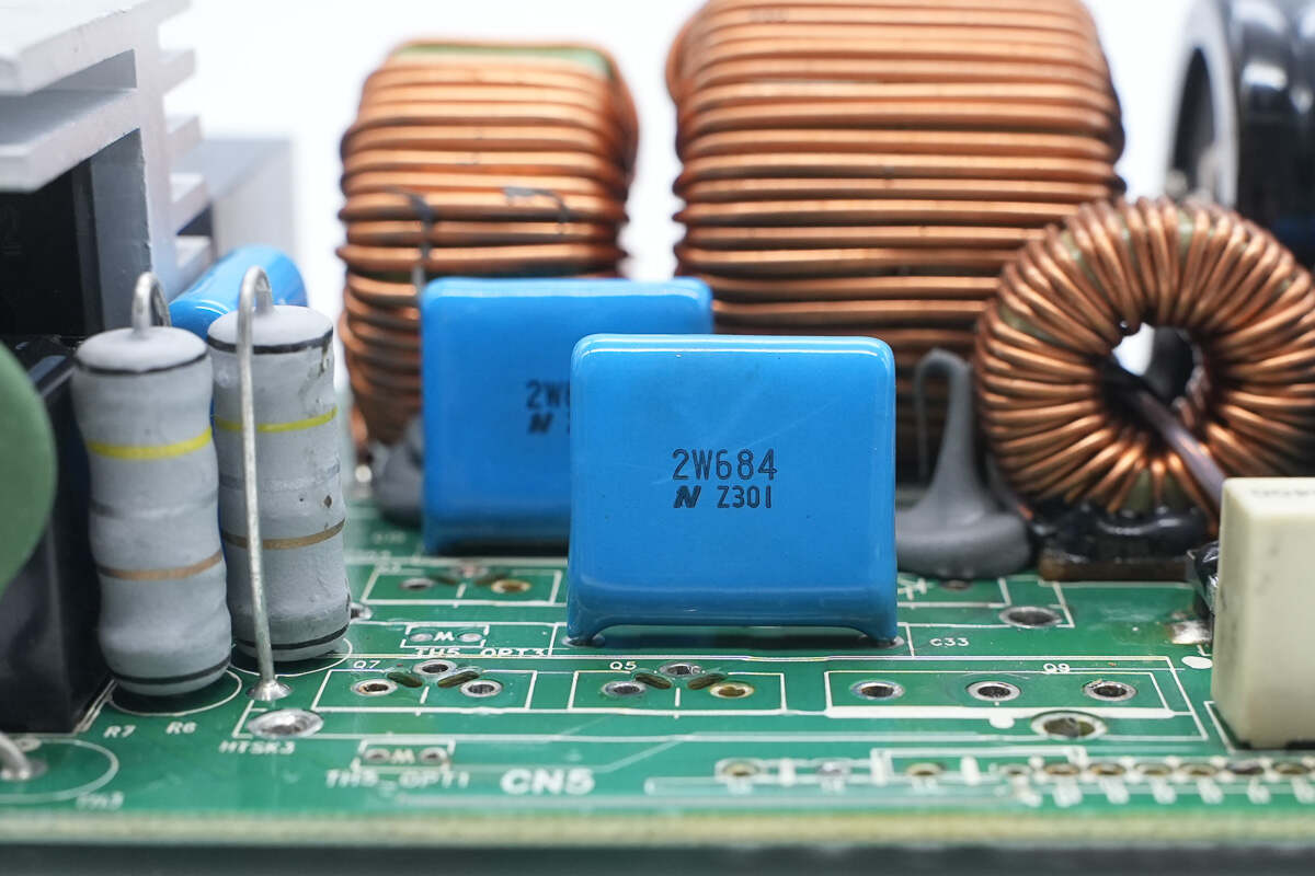
The film filter capacitor is from Nitsuko. 450V 0.68μF.
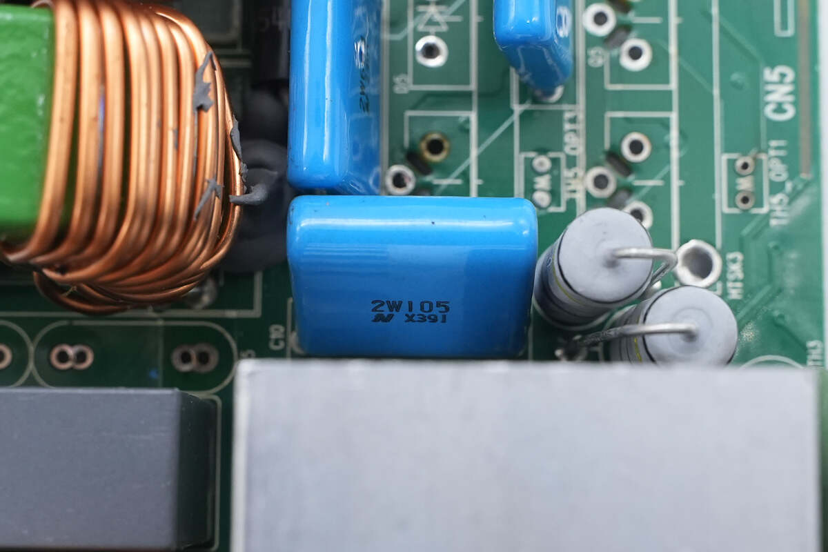
The other film filter capacitor is rated at 450V, 1μF.

The boost MOSFET is from STMicroelectronics, model STW25NM60ND. It is an N-channel MOSFET with a voltage rating of 600V, an on-resistance of 130mΩ, and comes in a TO-247 package.
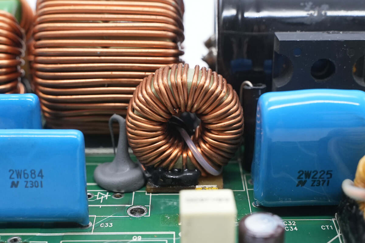
The bottom of the boost inductor is insulated with a Bakelite board.
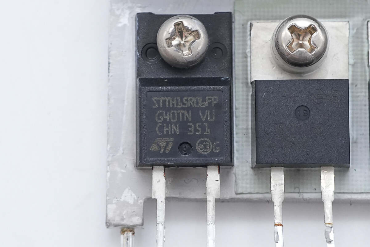
The rectifier is from STMicroelectronics, model STTH15R06FP. It is a Turbo 2 ultra-fast diode, rated at 600V and 15A, housed in a TO-220FPAC package.
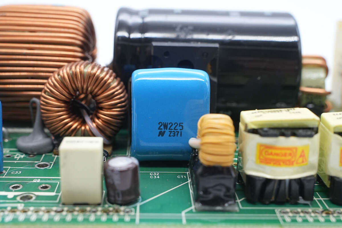
The film filter capacitor is rated at 450V, 2μF.
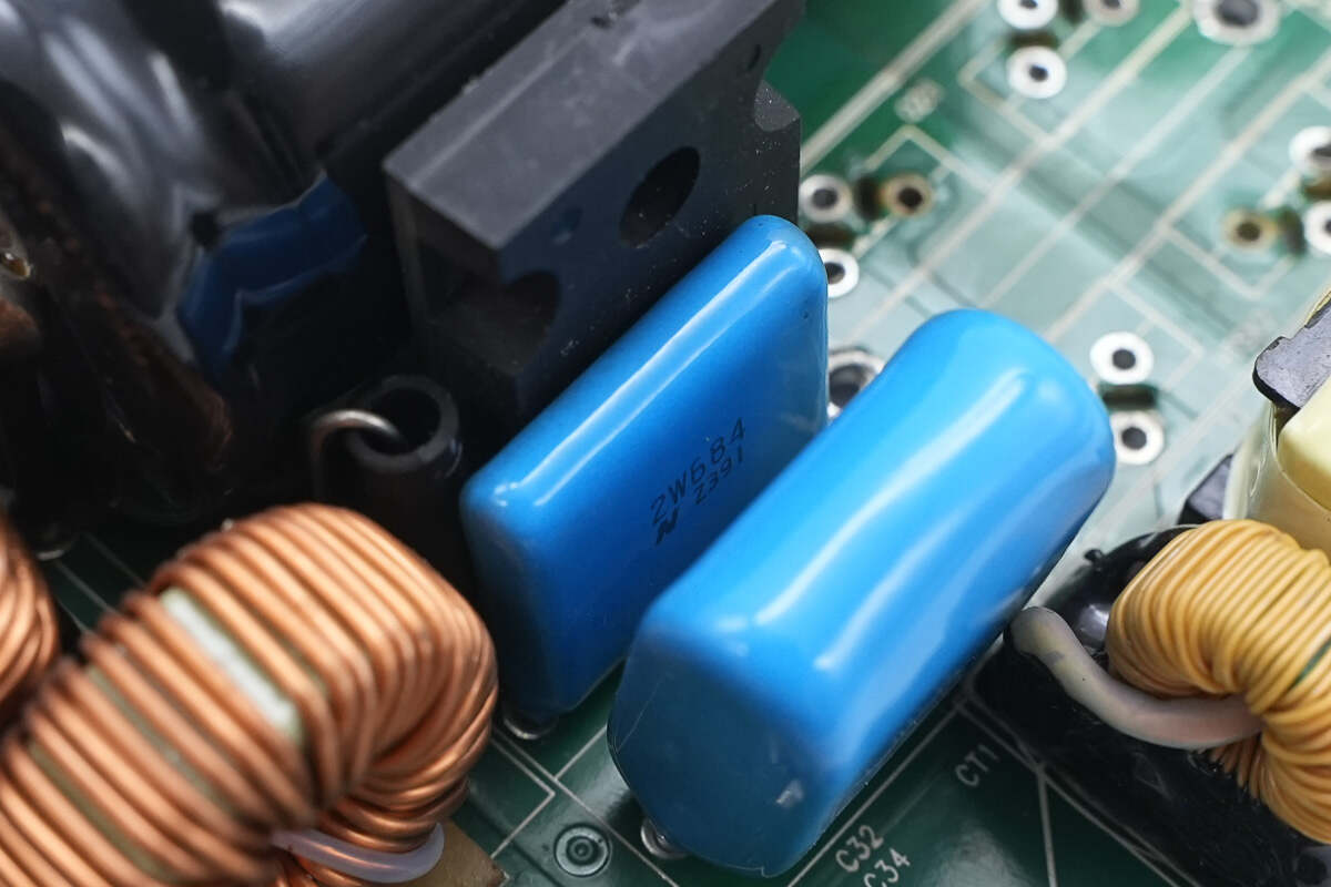
This film filter capacitor is rated at 450V, 0.68μF.
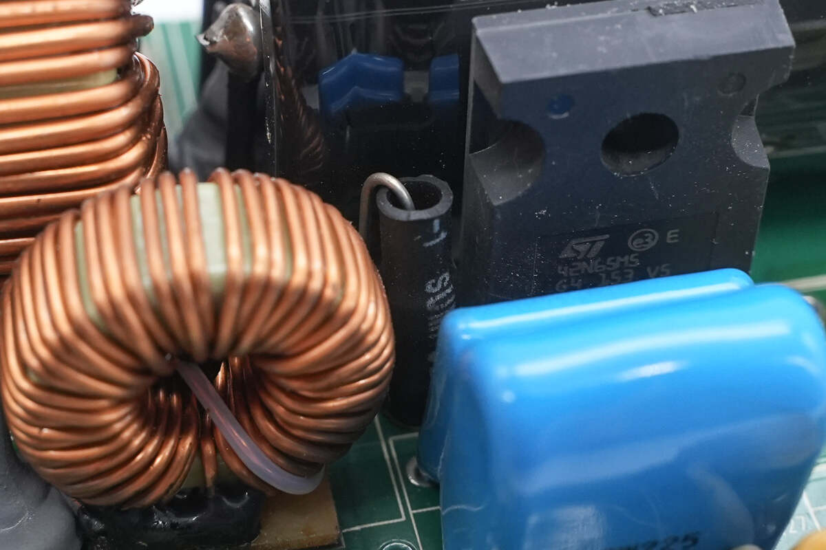
The fuse is insulated with heat-shrink tubing.
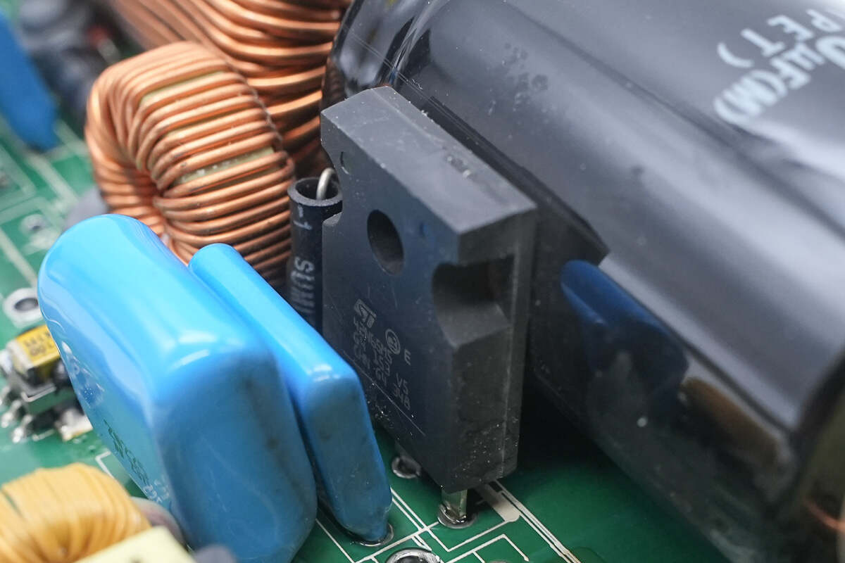
The switching MOSFET is from STMicroelectronics, model STW42N65M5. It is an N-channel MOSFET rated at 650V with an on-resistance of 71mΩ, housed in a TO-247 package.
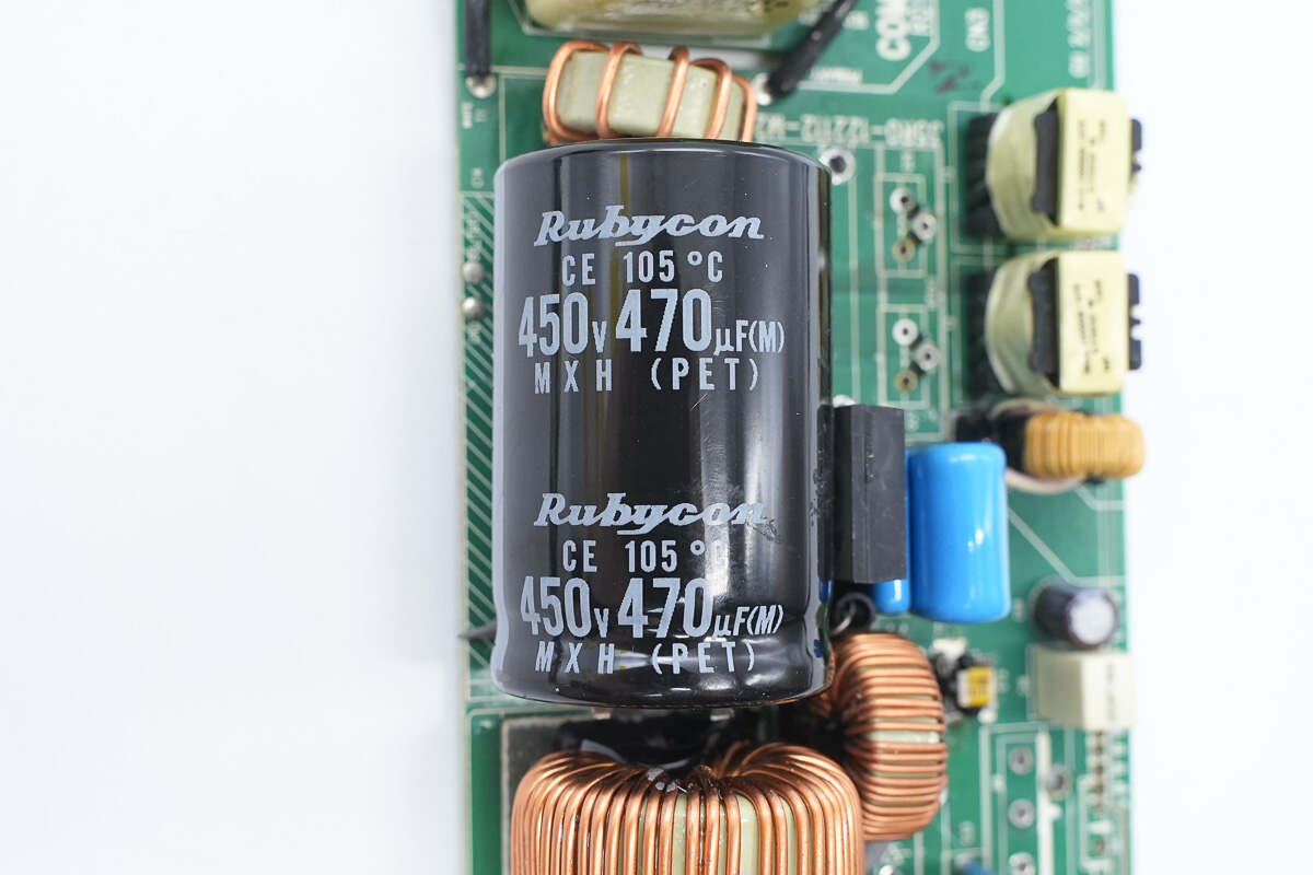
The high-voltage filter capacitor is from Rubycon, part of the MXH series. It is an electrolytic capacitor rated at 450V, 470μF.
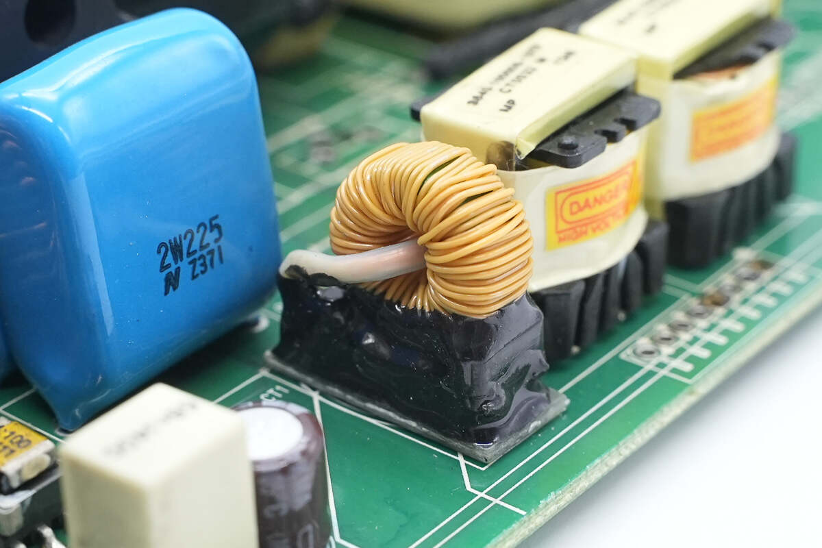
Close-up of the current transformer.
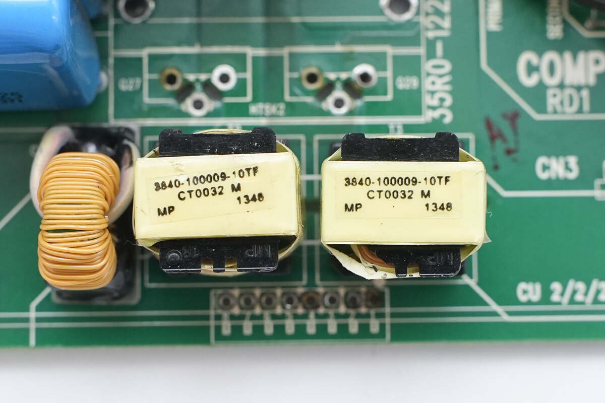
Two isolation transformers are used to drive the phase-shift full-bridge MOSFETs.
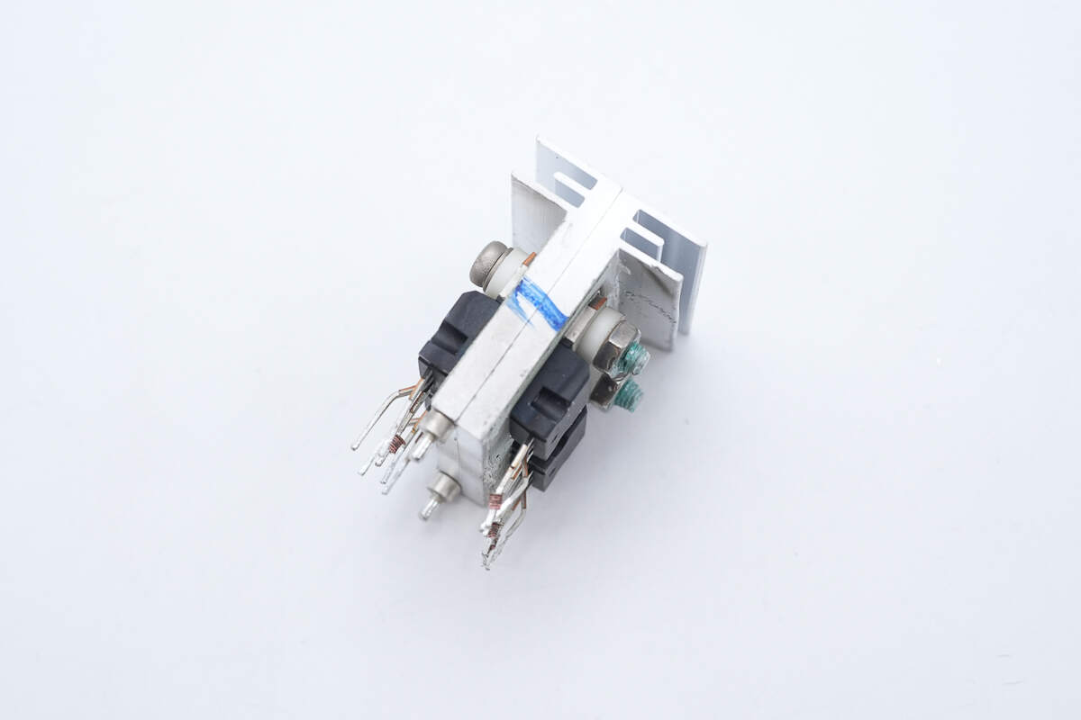
Four phase-shift full-bridge MOSFETs are mounted on the heatsink.
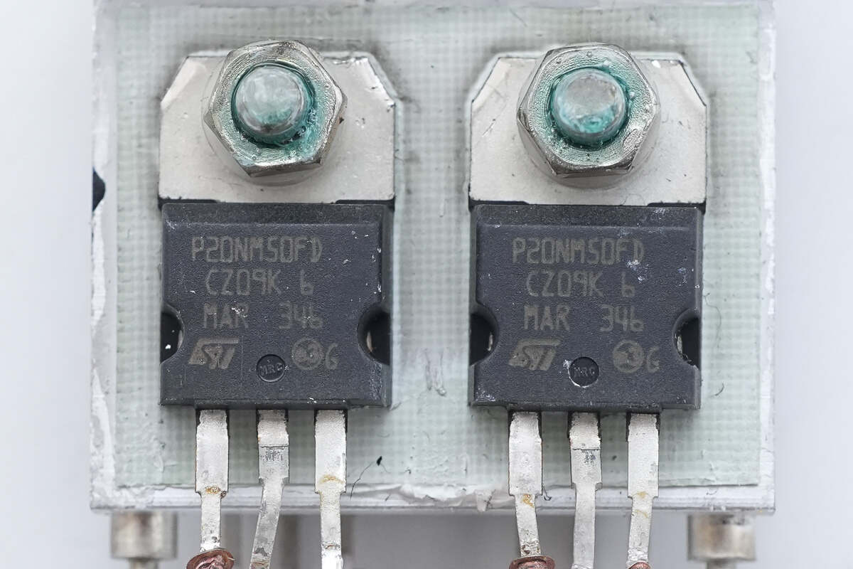
The MOSFETs are from STMicroelectronics, model STP20NM50FD. They are N-channel MOSFETs rated at 500V with an on-resistance of 220mΩ, housed in a TO-220 package.
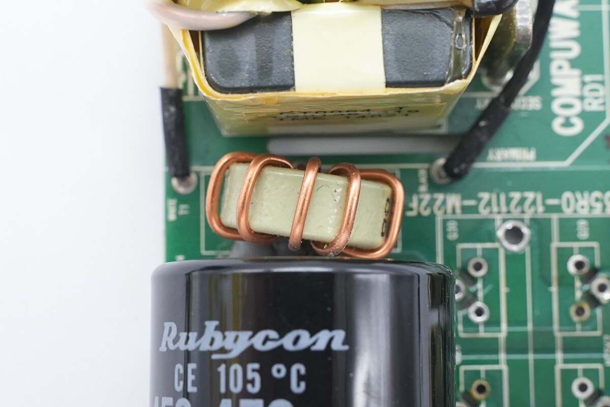
The resonant inductor is wound on a ferrite core.
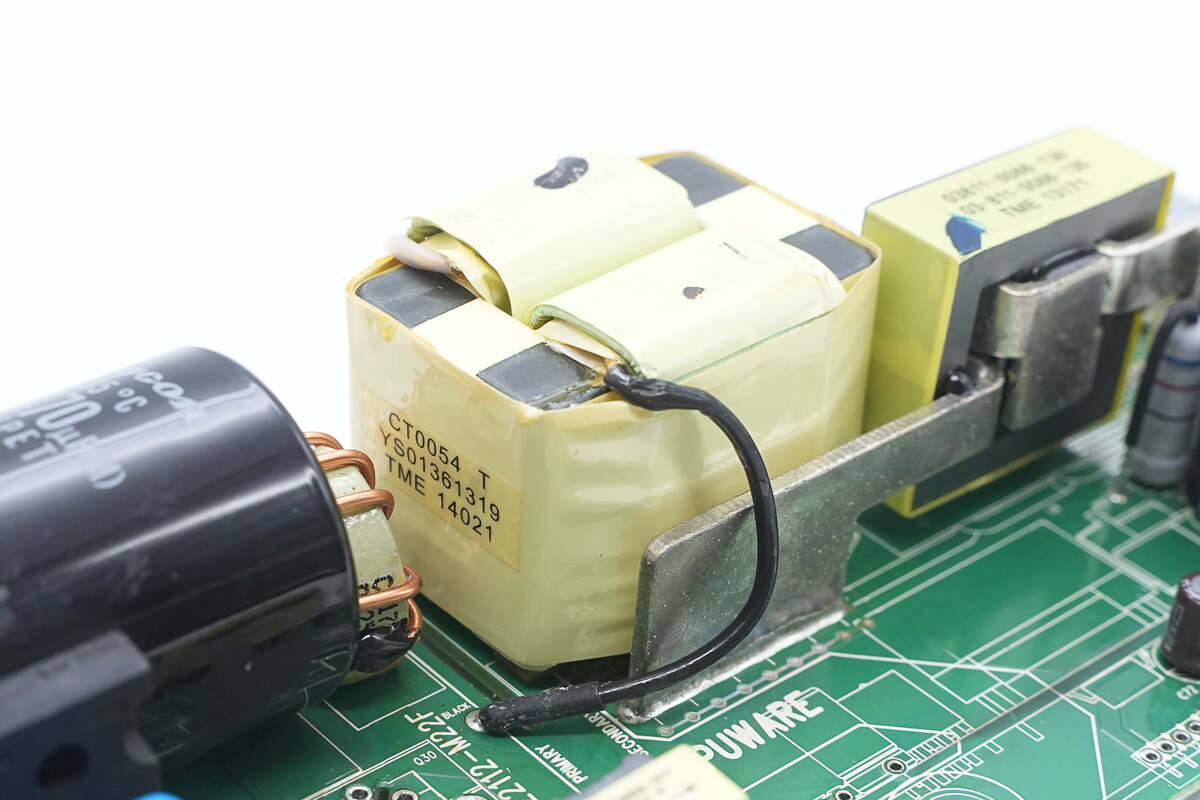
The transformer’s primary winding is made with Litz wire, while the secondary winding uses soldered copper strips.
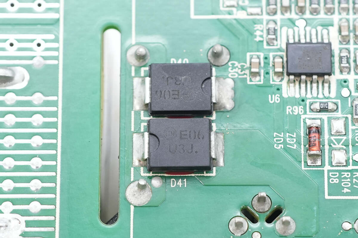
Two fast recovery diodes from Onsemi, marked U3J, model MURS360, rated at 600V 3A, are housed in SMC packages.
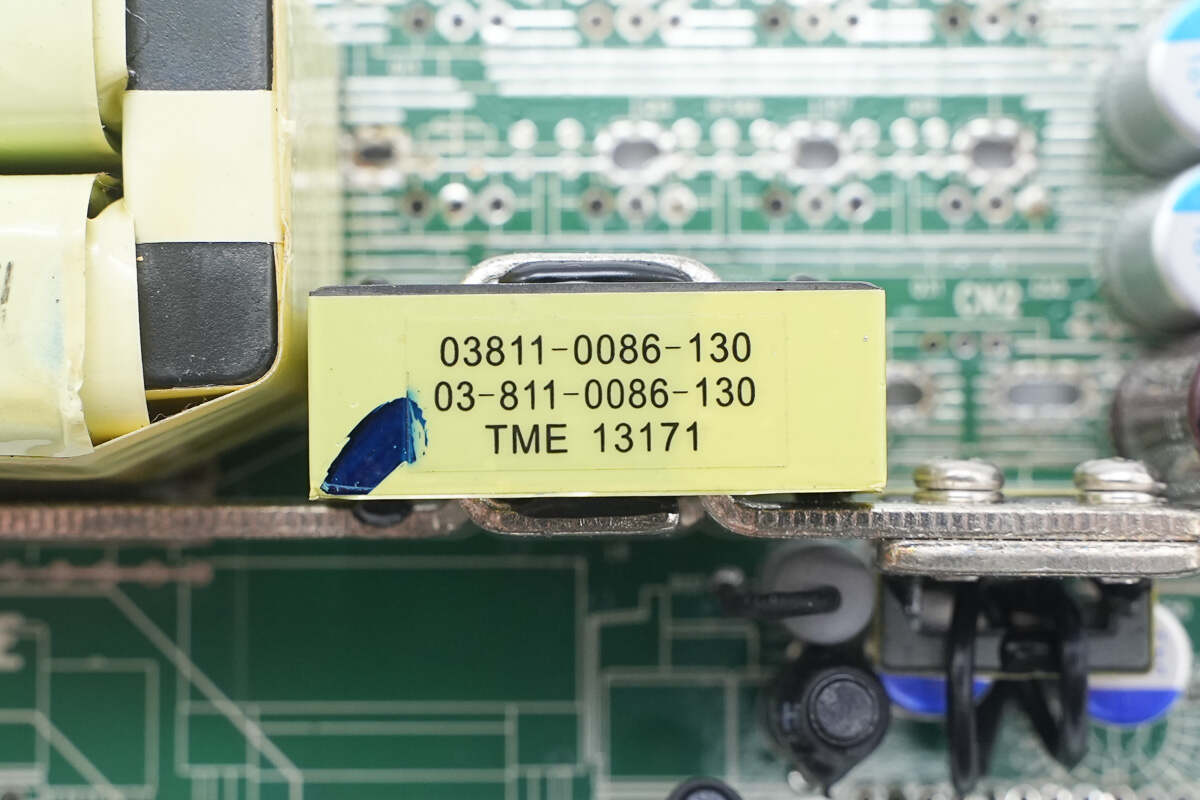
Here is the filter inductor.
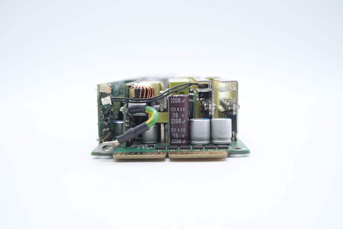
The output side includes filter capacitors and synchronous rectifiers.
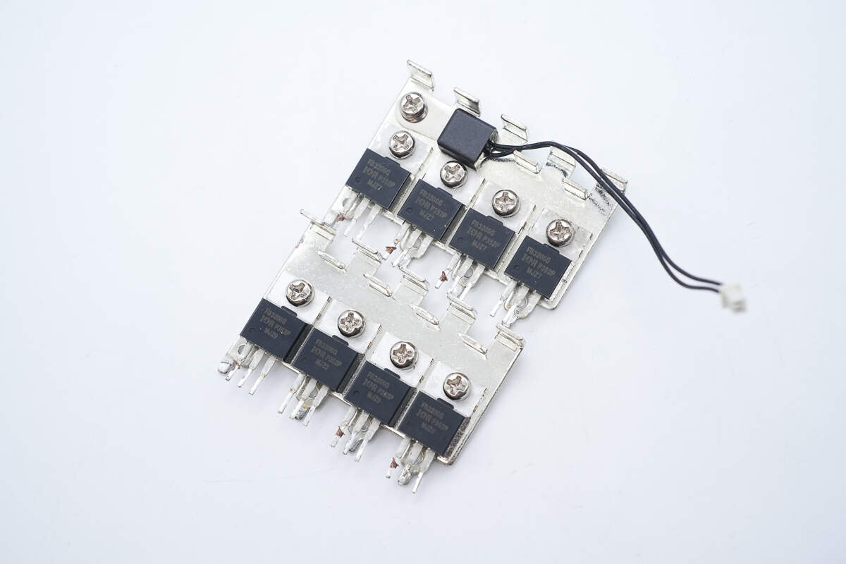
The synchronous rectifiers are mounted on heatsinks.
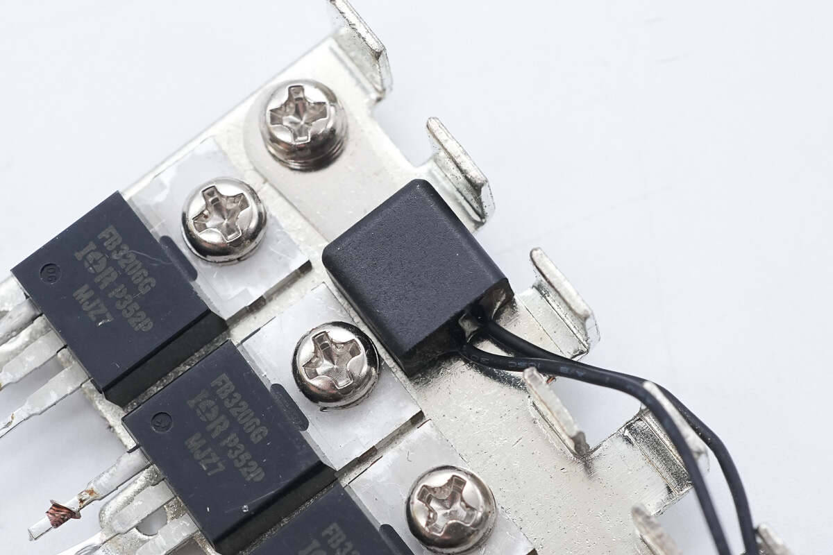
A thermistor is mounted on the heatsink to monitor temperature.
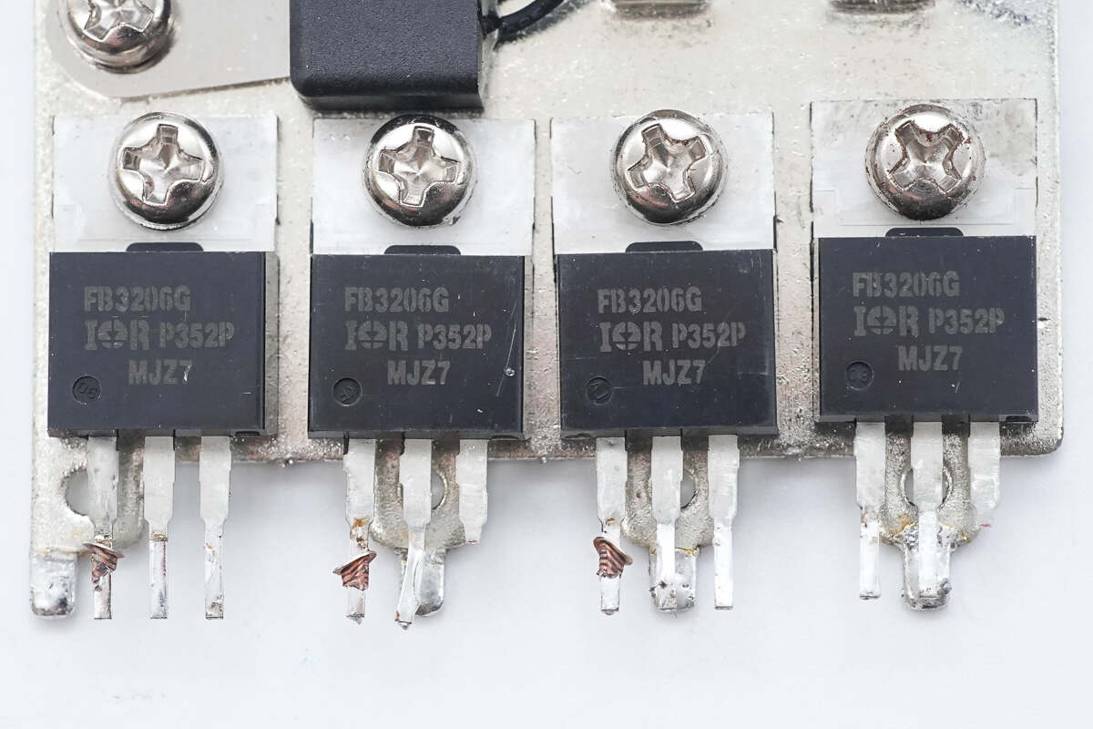
The synchronous rectifiers are from Infineon, model IRFB3206G. They are N-channel MOSFETs rated at 60V with an on-resistance of 2.4mΩ, housed in TO-220AB packages.
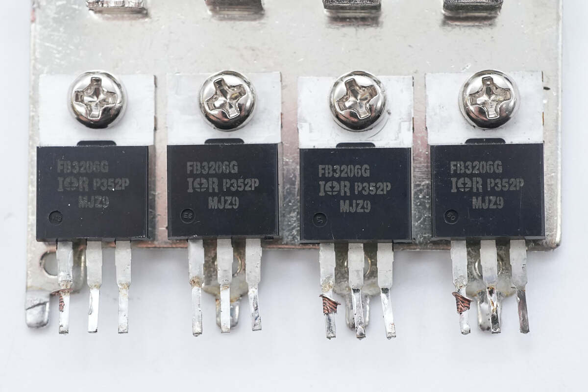
The other four synchronous rectifiers have the same model.
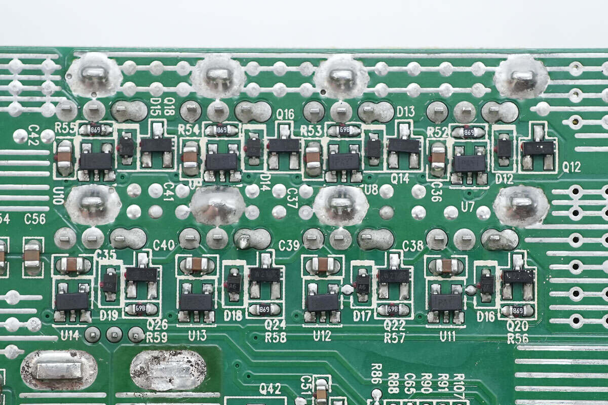
There are eight driver ICs, each corresponding to one of the eight synchronous rectifiers.
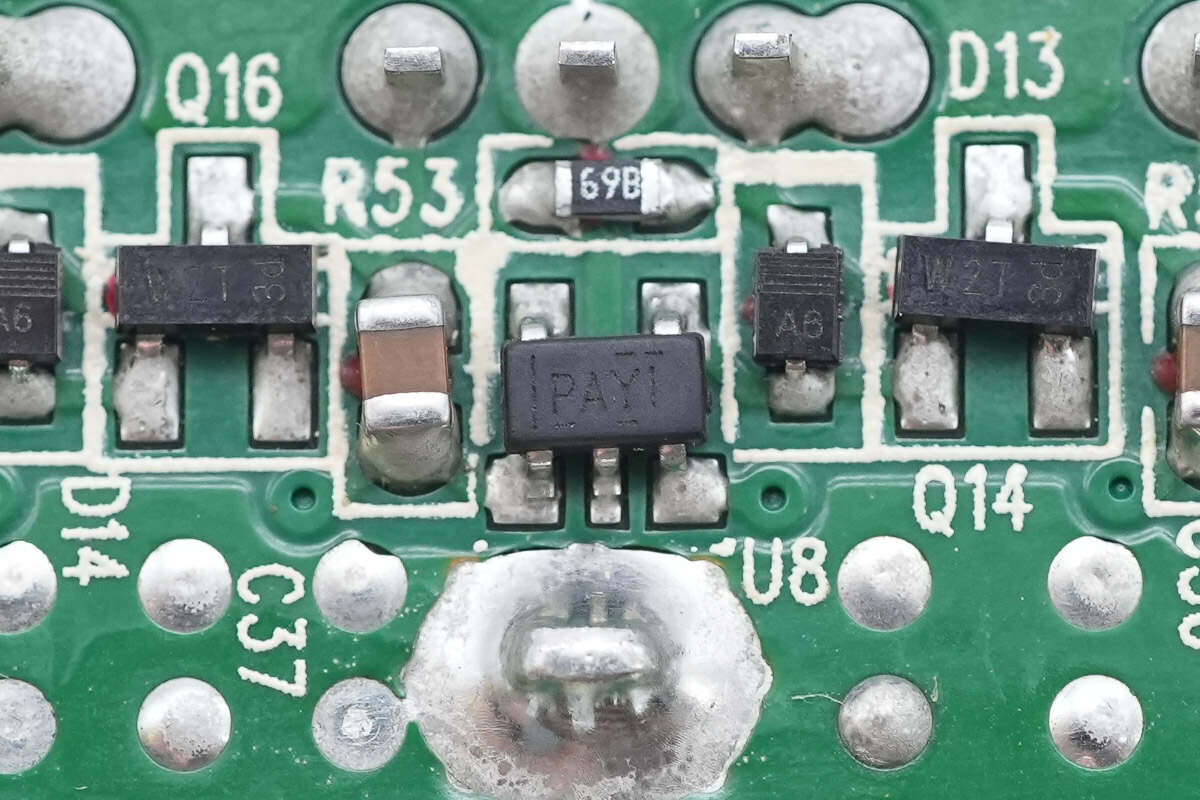
The drivers are TI TPS2819, the same model used for the PFC MOSFET drivers.
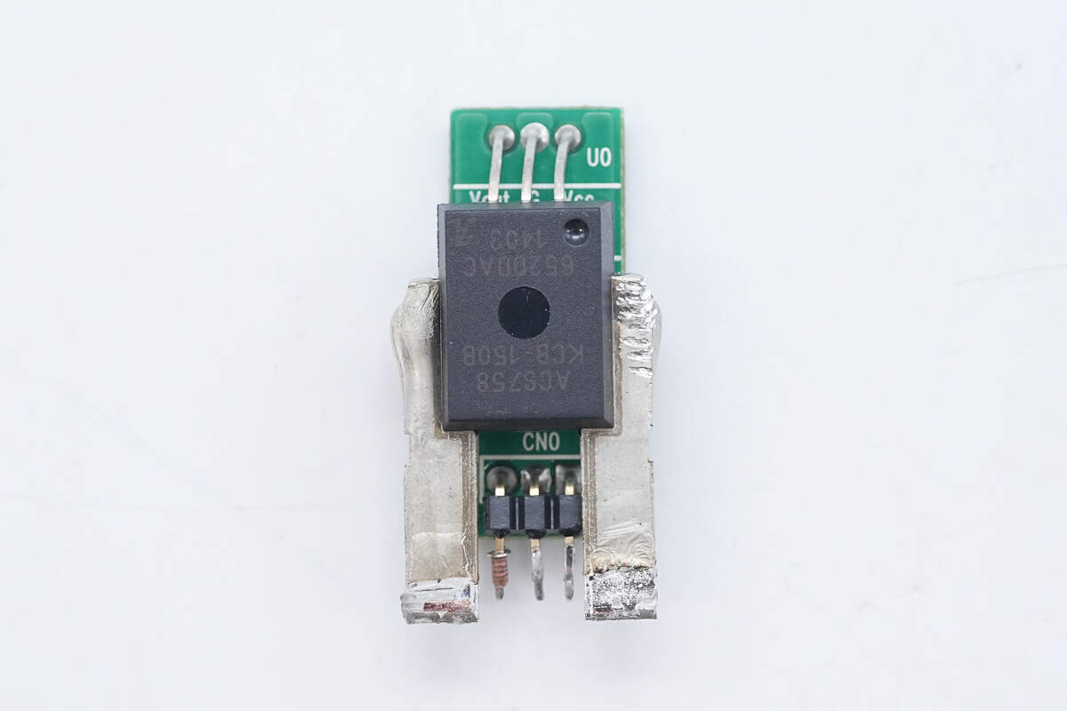
A Hall-effect current sensor is used to monitor the output current.
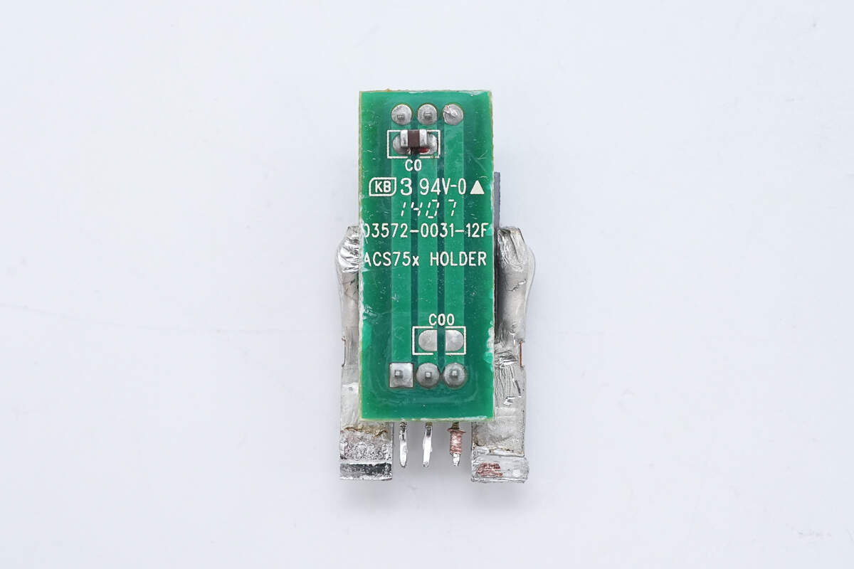
A small PCB is soldered to the back of the sensor for connections.
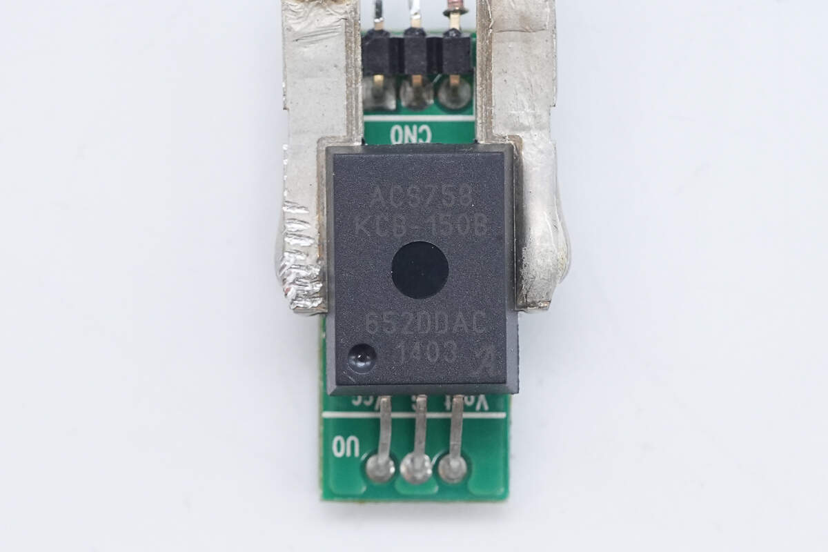
The Hall-effect current sensor is from Allegro, model ACS758KCB-150-PSF-T. It features a built-in 100μΩ sense resistor and an integrated low-offset, precision linear Hall sensor circuit. It supports bidirectional current sensing up to 150A, operates at 3.3V or 5V, and comes in a 5-pin package.
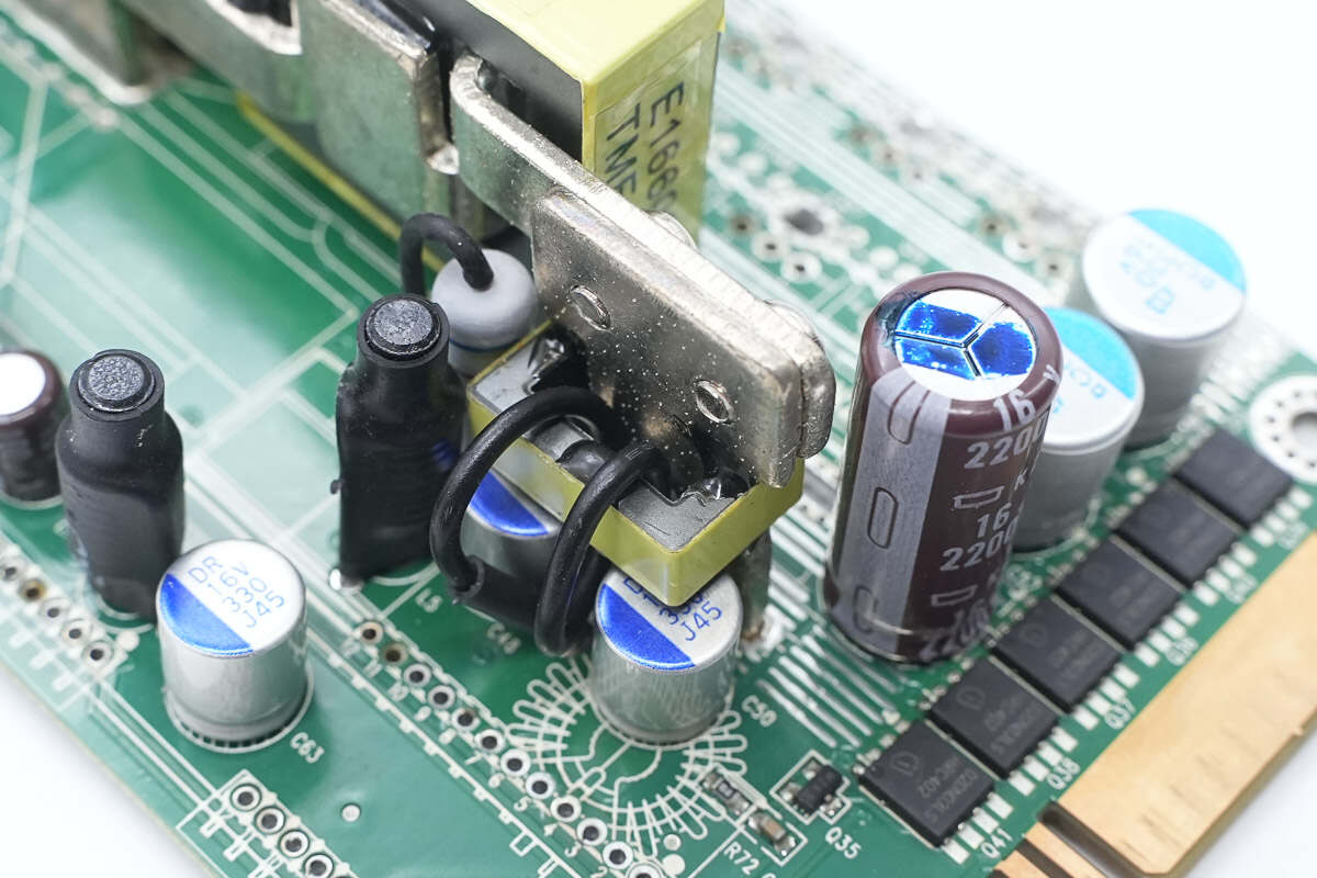
The output side features a filter ferrite core.
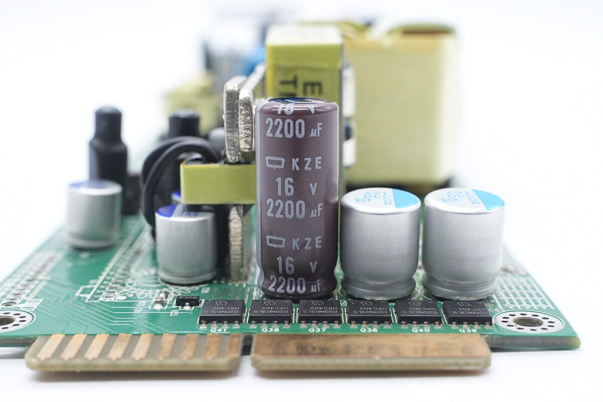
The filter capacitor is from NCC, part of the KZE series of long-life electrolytic capacitors, rated at 16V, 2200μF.

The solid capacitors are also from NCC, each rated at 330μF, 16V.
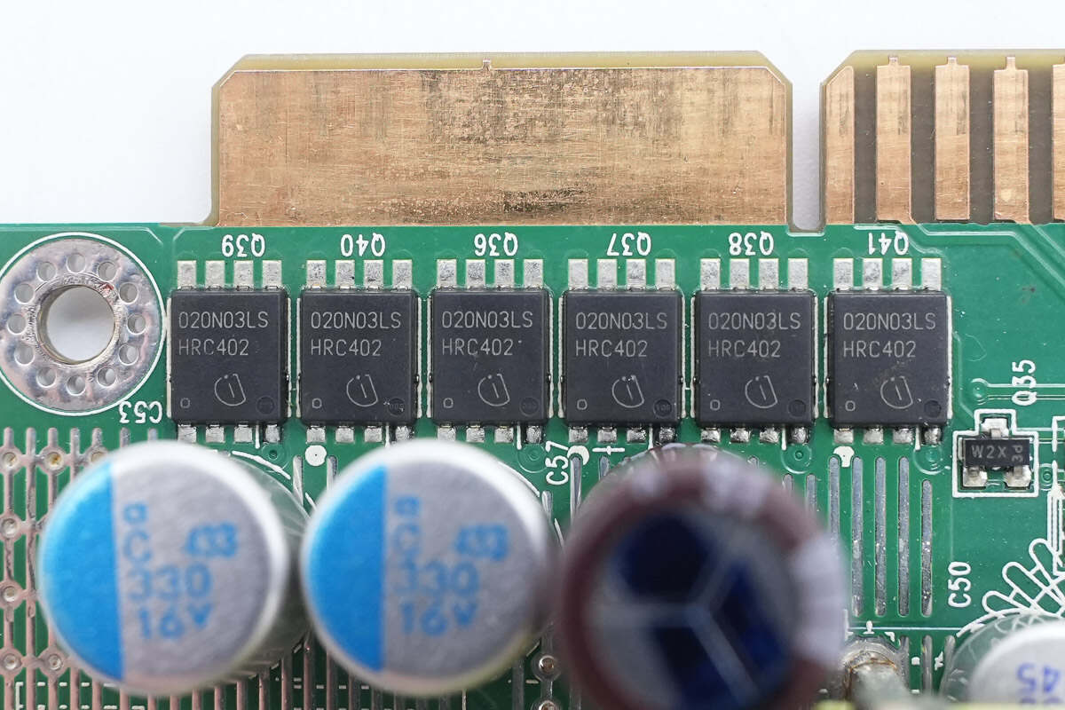
The output control MOSFETs are from Infineon, model BSC020N03LS. They are N-channel MOSFETs rated at 30V with an on-resistance of 2mΩ, housed in a TDSON-8 package.
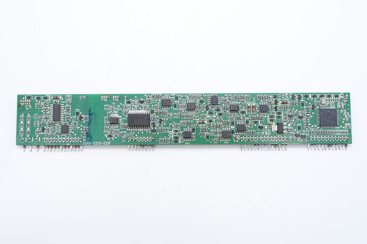
On the left side of the control PCB are a PFC controller and an Op-Amp. In the center are a phase-shift full-bridge controller, a voltage comparator, and an Op-Amp. The right side houses the MCU.
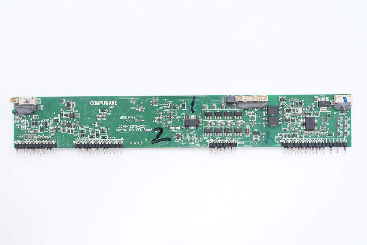
The back side features a NAND gate, transistors, optocouplers, and an MCU.
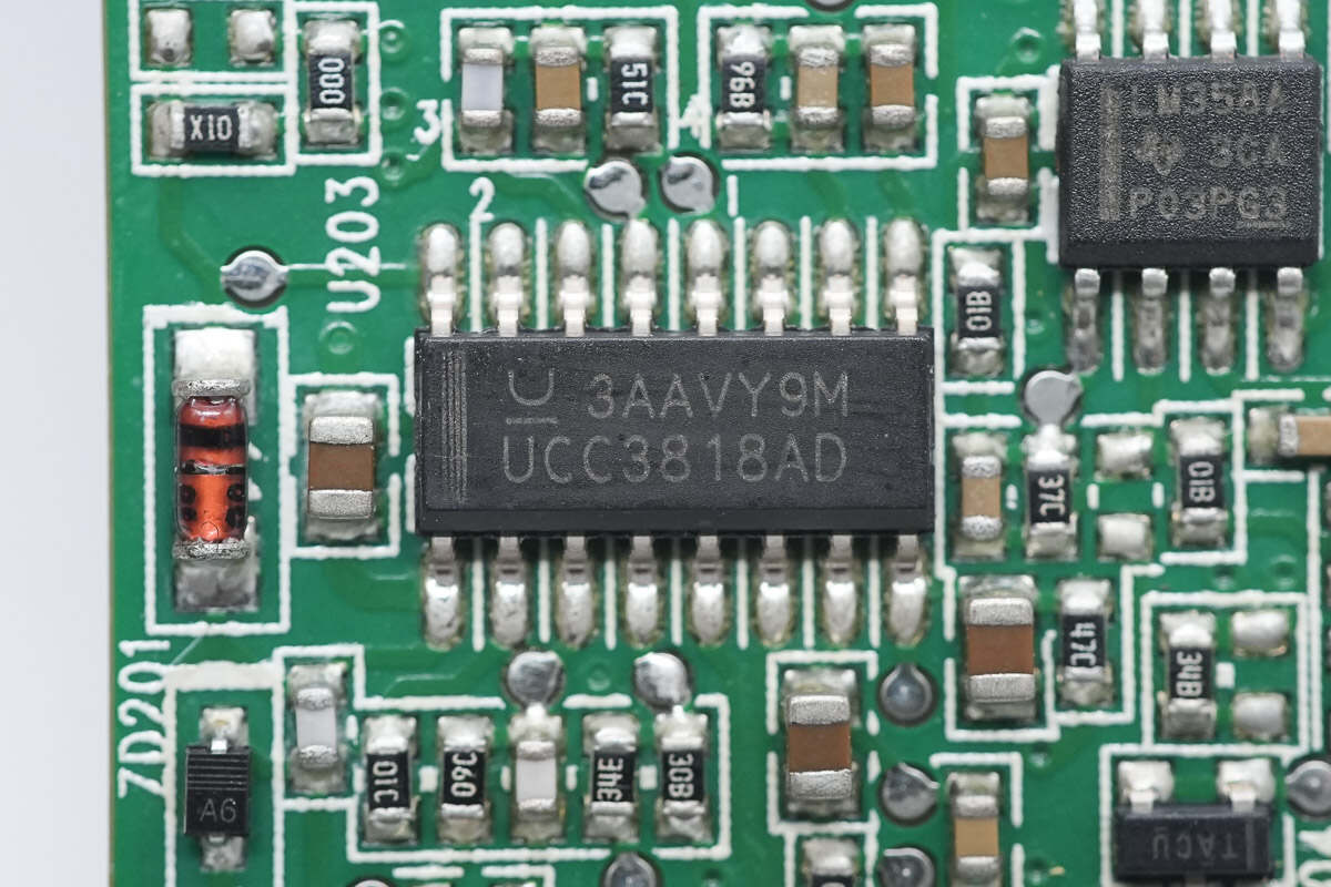
The PFC controller is from TI, model UCC3818AD. It is a CCM-mode PFC controller featuring overvoltage protection and precise power limiting, housed in a 16-pin SOIC package.
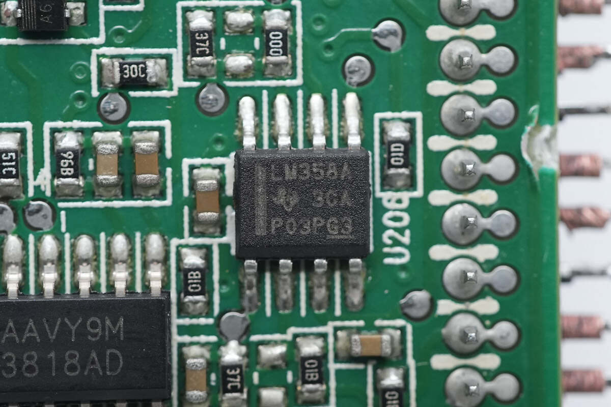
The Op-Amp is from Texas Instruments, model LM358A. It is a general-purpose dual op-amp, housed in an 8-pin SOIC package.
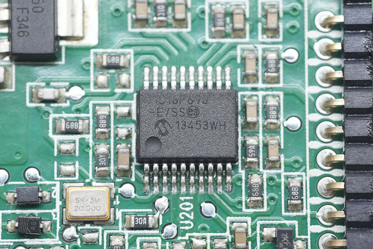
The MCU is from Microchip, model PIC16F690. It features a high-performance RISC core CPU, 7KB of internal FLASH, 256 bytes of SRAM, 256 bytes of EEPROM, an integrated 10-bit ADC, and comes in a 20-pin SSOP package.
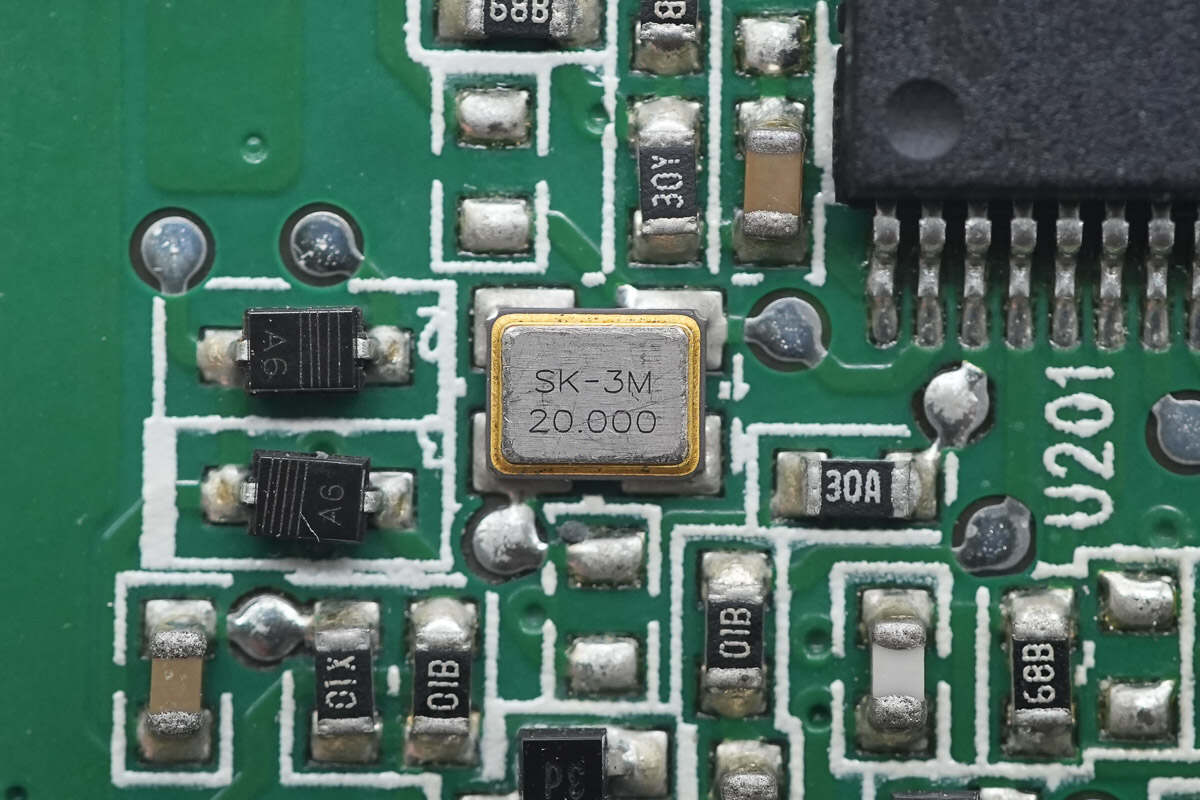
Close-up of the external 20.000 MHz clock crystal oscillator for the MCU.
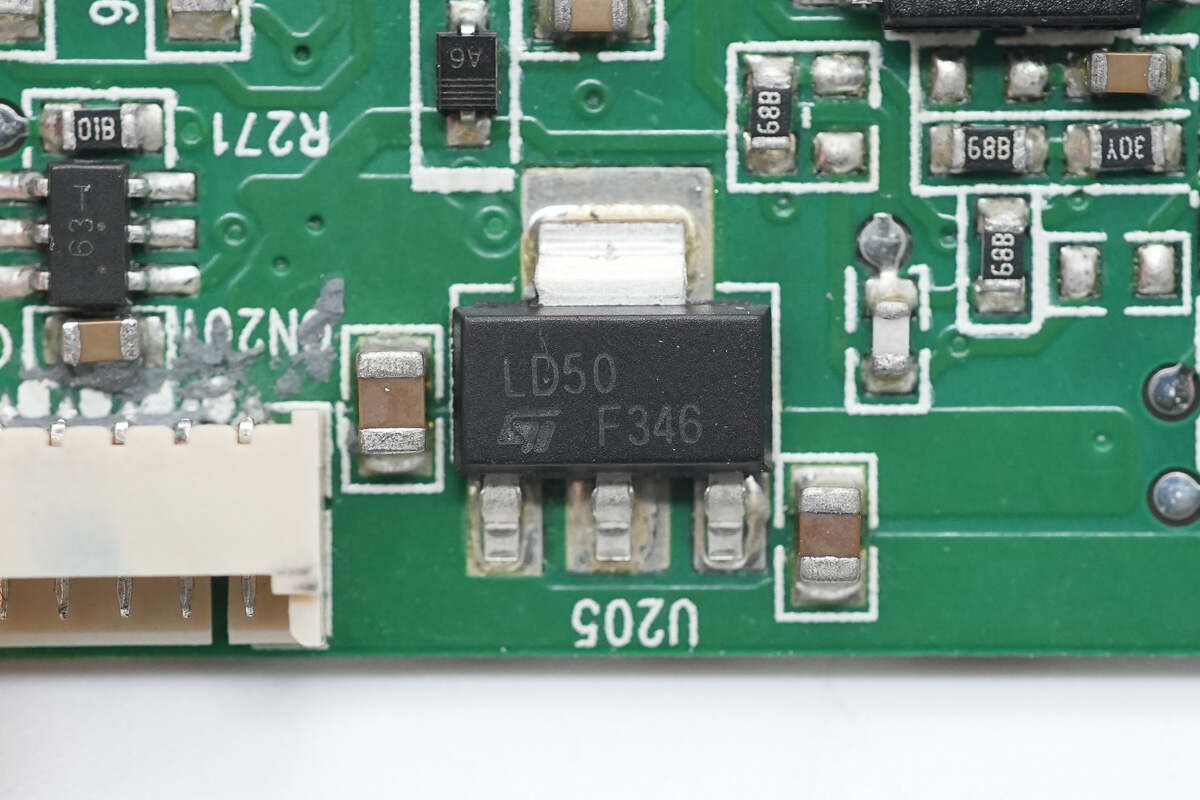
The voltage regulator supplying power to the MCU is from STMicroelectronics, marked LD50, model LD1117S50TR. It supports a 15V input voltage, outputs 5V at up to 800mA, and comes in a SOT-223 package.
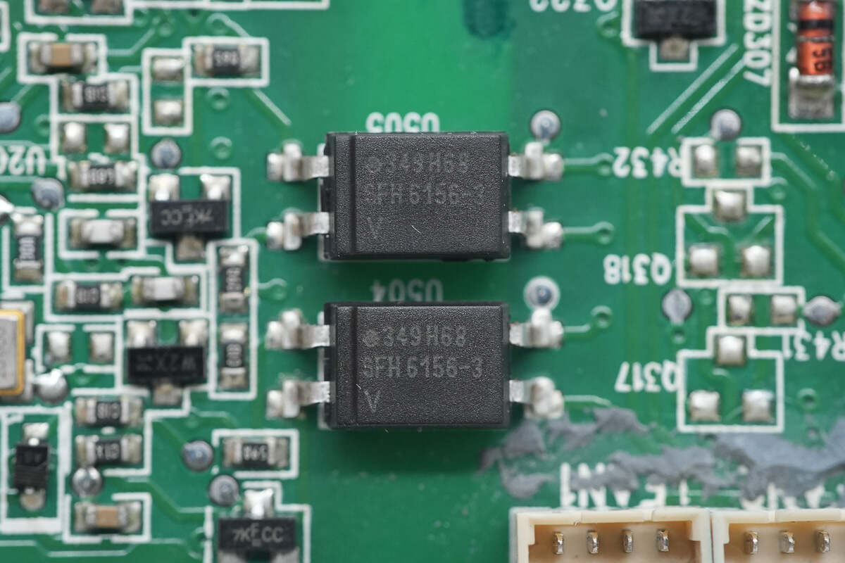
The isolation optocouplers are from VISHAY, model SFH6156-3.
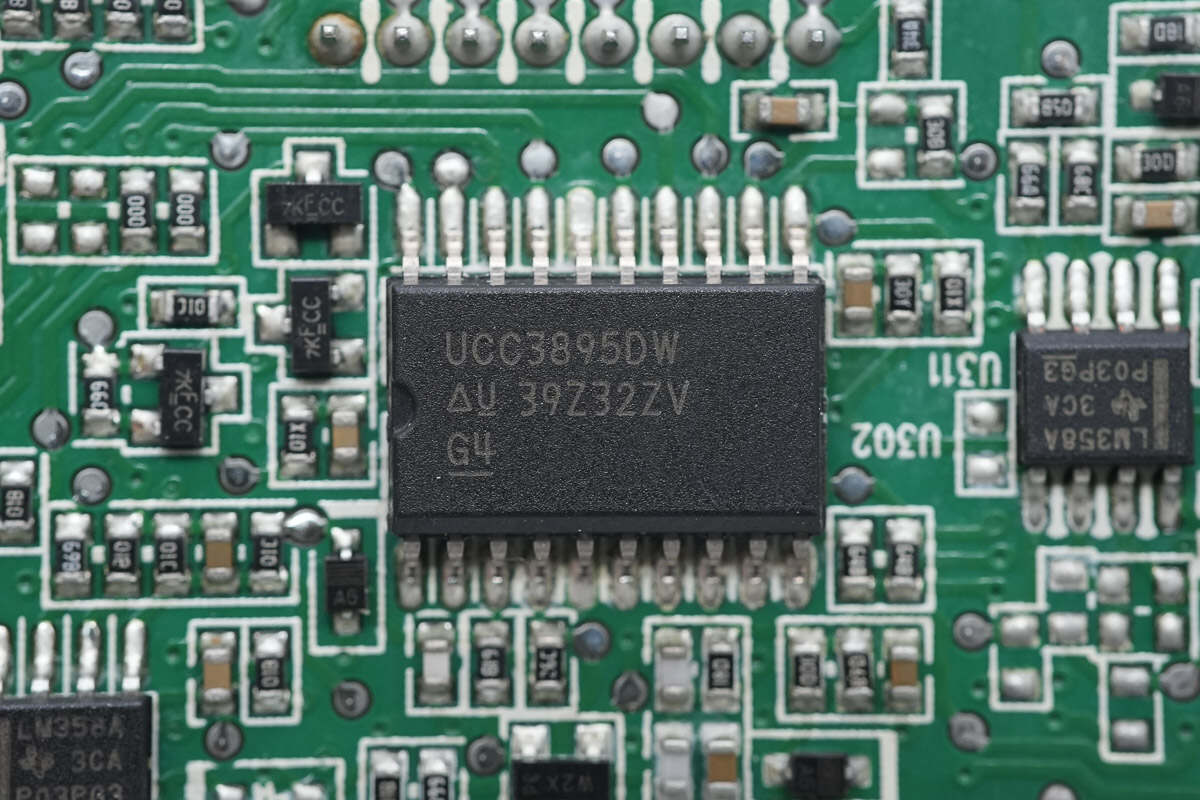
The phase-shift full-bridge controller is from TI, model UCC3895. It supports fixed-frequency PWM and resonant zero-voltage switching, with both voltage-mode and current-mode control. The chip features enhanced control logic, adaptive delay settings, and shutdown functionality, housed in a 20-pin SOIC package.
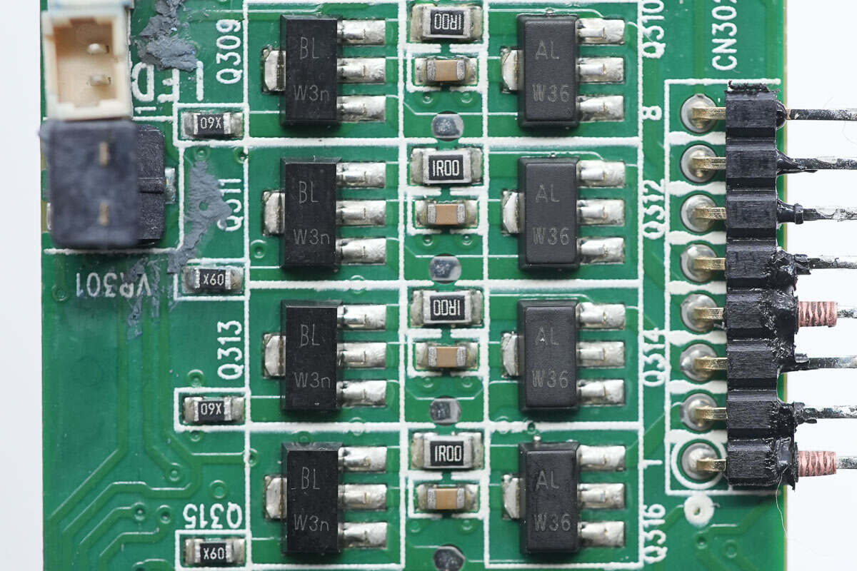
Close-up of the transistors driving the isolation transformers.
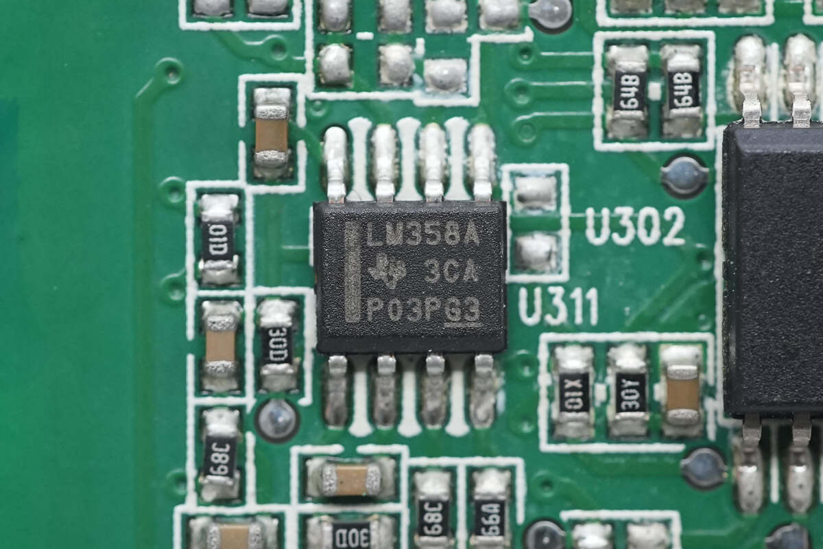
Close-up of the LM358A dual op-amp; a total of six are installed.
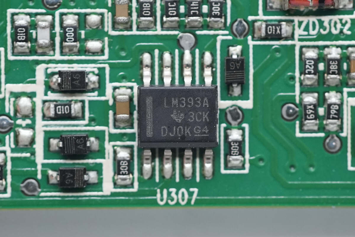
Close-up of the LM393A dual voltage comparator; a total of four are installed.
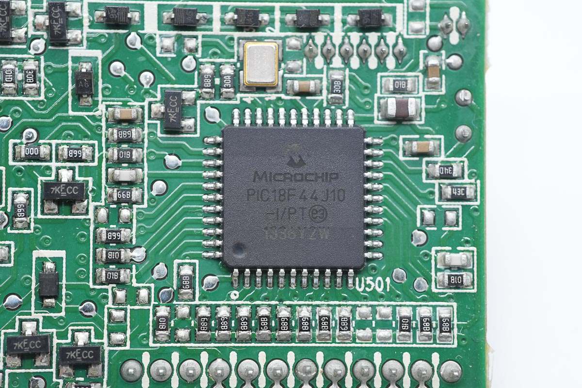
The main MCU is from Microchip, model PIC18F44J10. It features 16KB of internal FLASH and 1KB of RAM, housed in a 44-pin TQFP package.
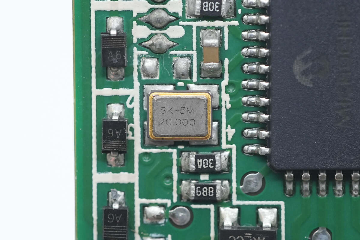
Close-up of the 20.000 MHz clock crystal oscillator.
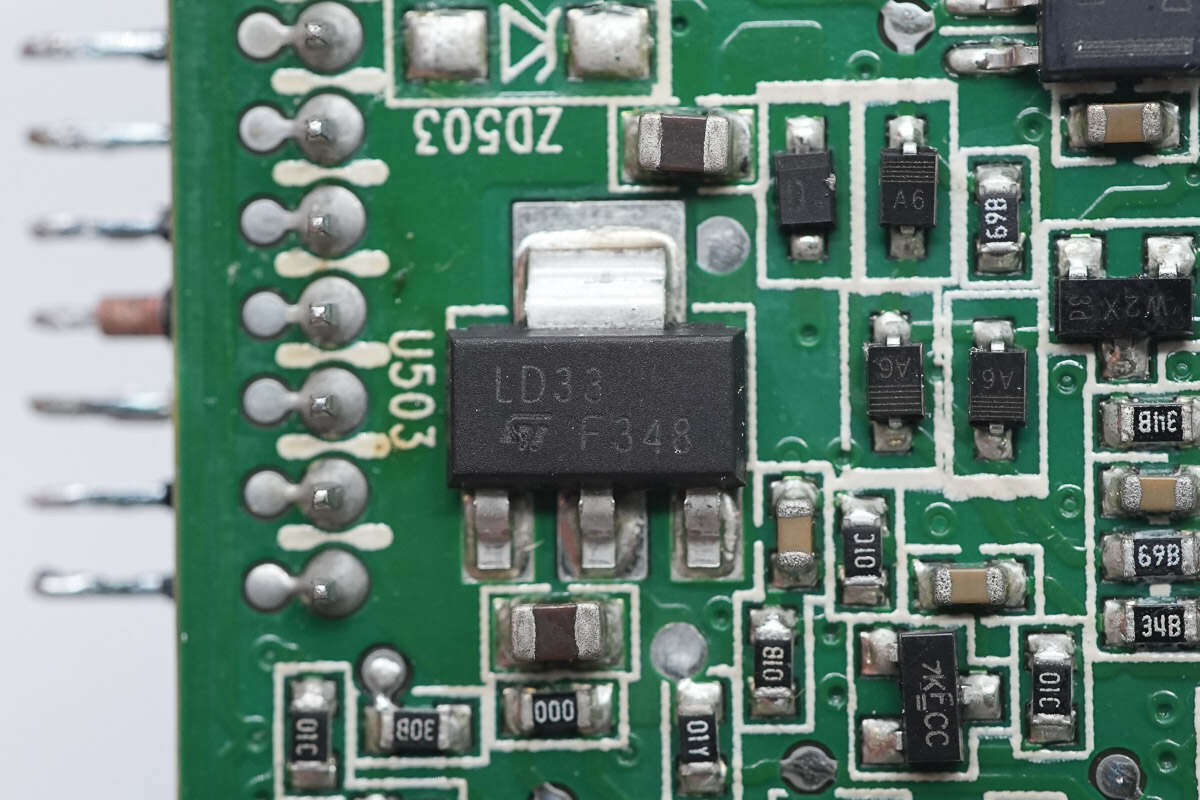
The voltage regulator supplying power to the MCU is from STMicroelectronics, marked LD33, model LD1117S33TR. It supports up to 15V input voltage, outputs 3.3V at 800mA, and comes in a SOT-223 package.
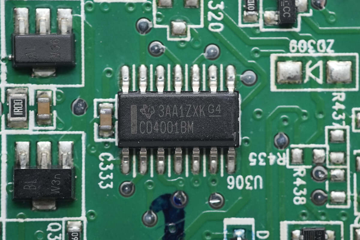
The NAND gate is from TI, model CD4001BM. It is a quad 2-input device housed in a 14-pin SOIC package.
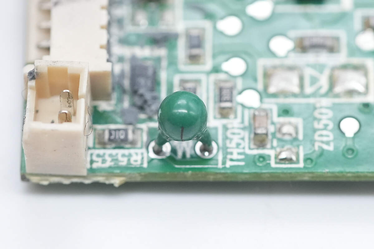
Close-up of the thermistor used for internal temperature sensing of the power supply.
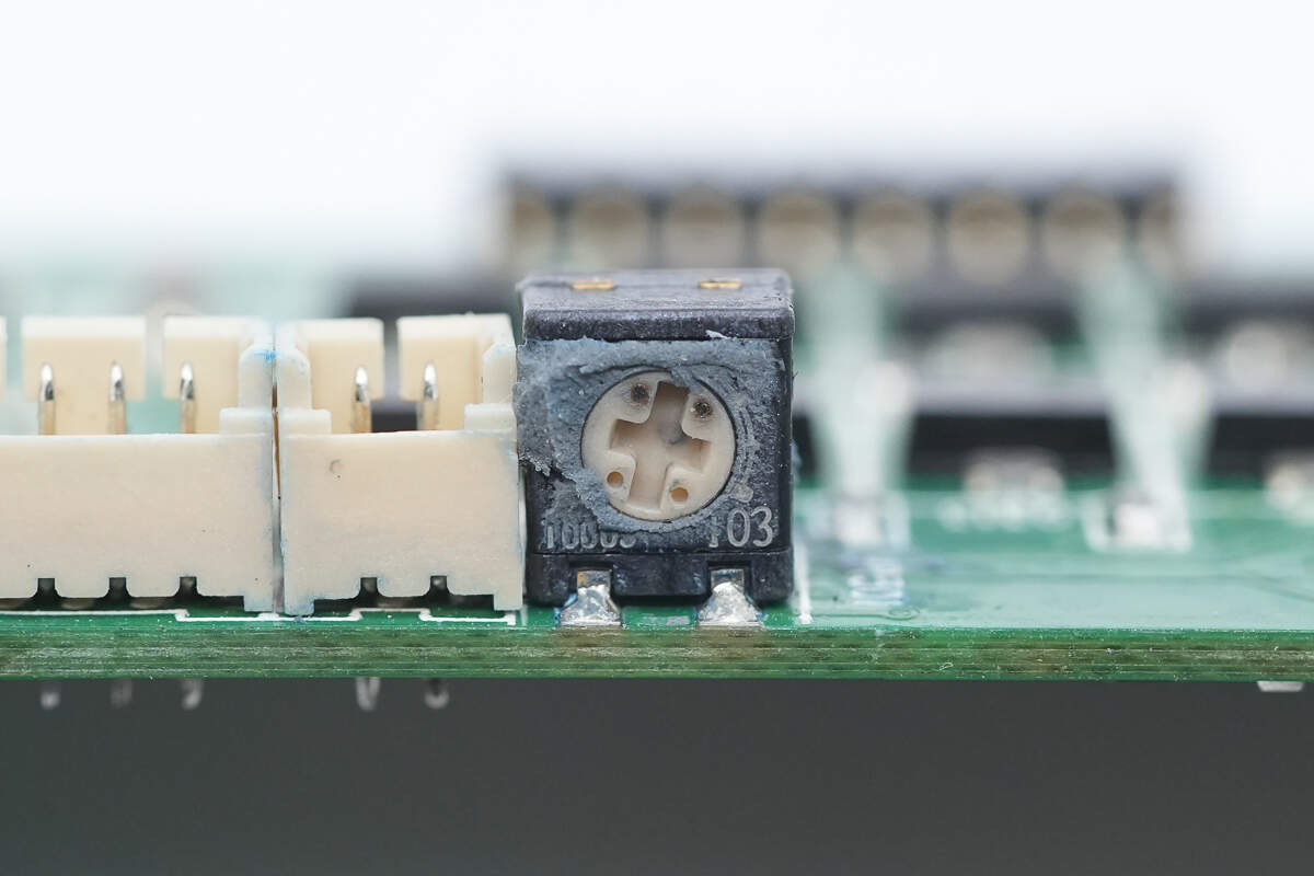
Close-up of the 10kΩ potentiometer.
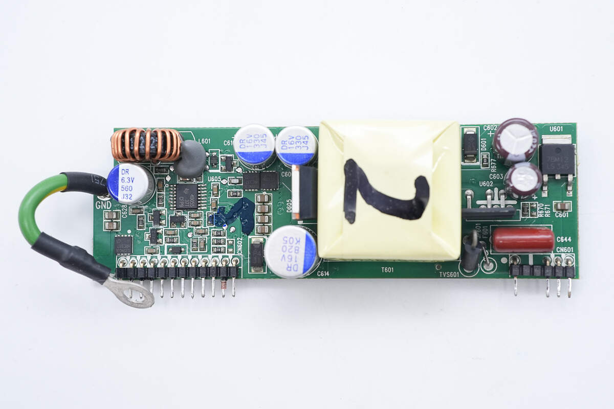
On the right side of the standby power PCB are the switching power IC, the voltage regulator, and filter capacitors. In the middle are the transformer, rectifier, and solid capacitors. The left side features the synchronous buck controller, buck MOSFETs, and a filter capacitor.
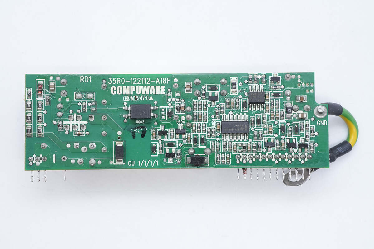
On the back side are an optocoupler, voltage comparators, and operational amplifiers.
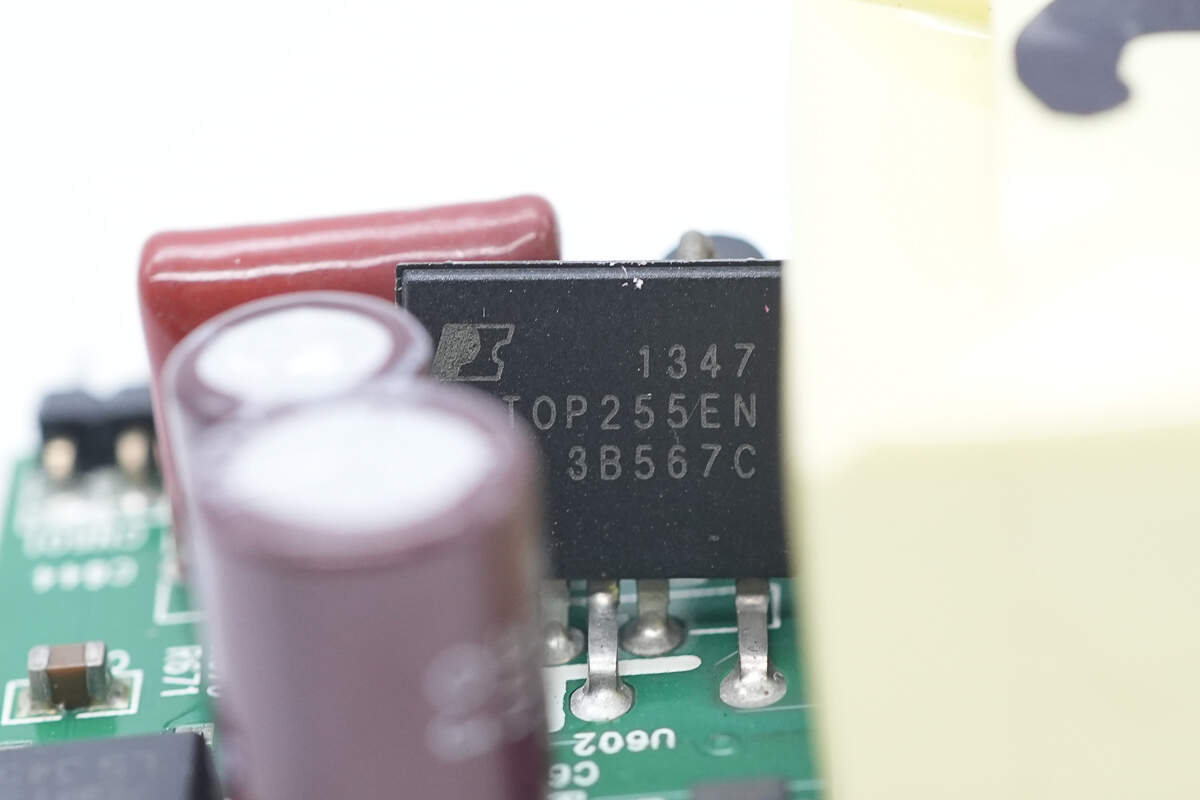
The switching power IC is from PI, model TOP255EN. It integrates both the controller and MOSFET internally, supports wide voltage adapter environments with 26W output power, and comes in an eSIP-7F package.
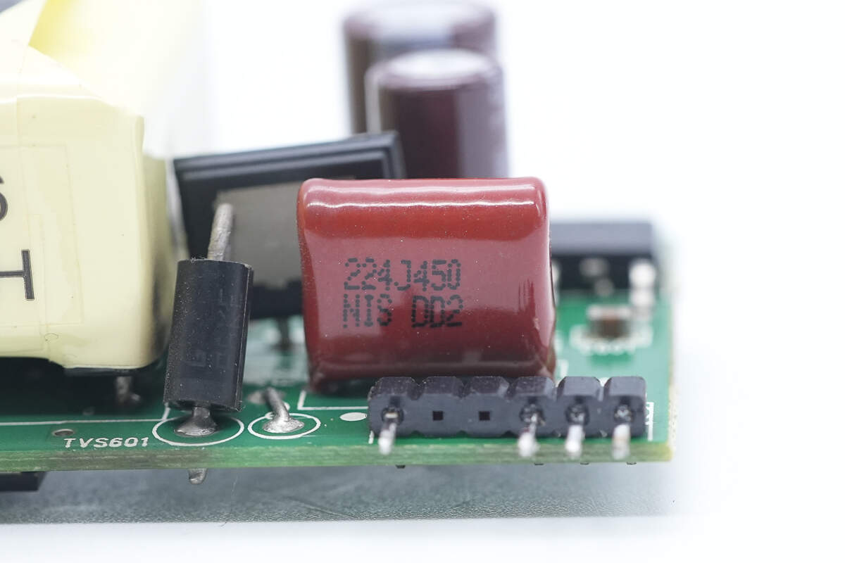
The film filter capacitor is rated at 0.22μF, 450V.
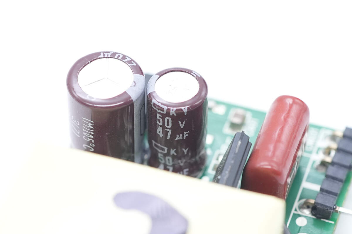
The filter capacitor is from NCC, rated at 47μF, 50V.
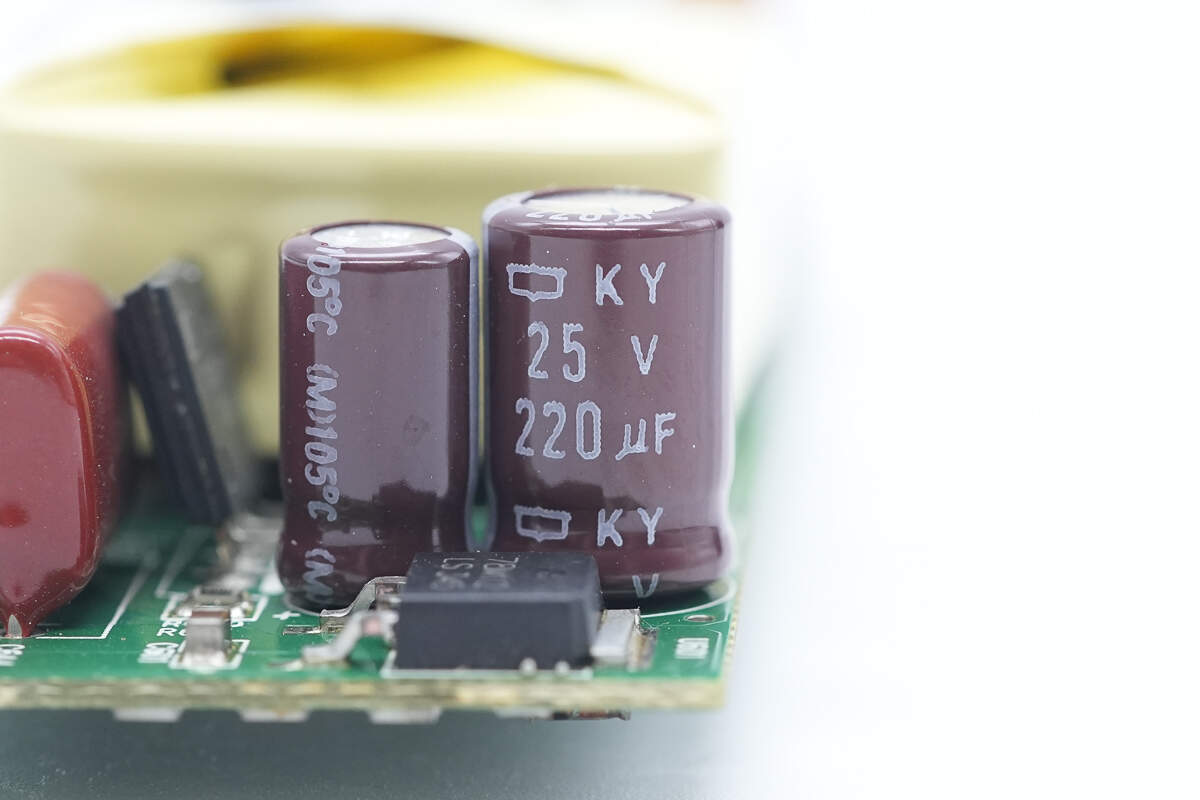
Another capacitor is rated at 220μF, 25V.
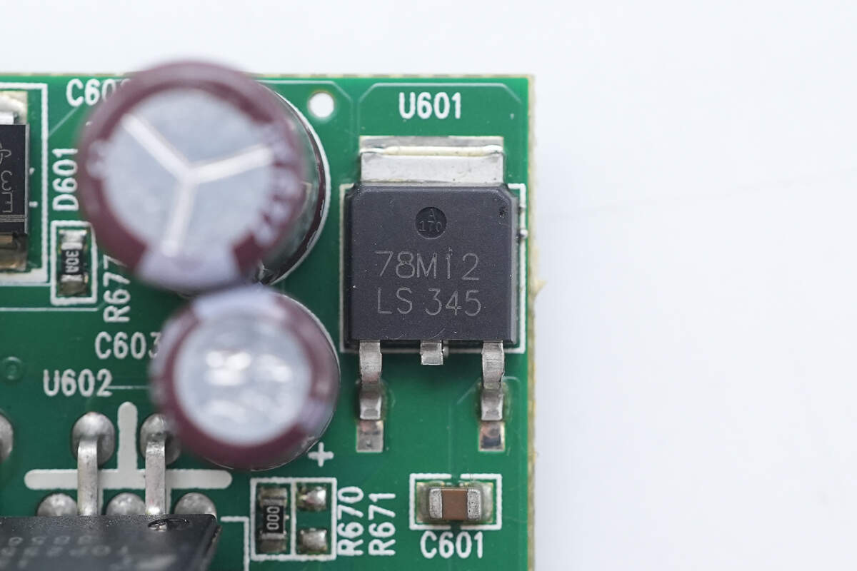
The voltage regulator chip is model 78M12, with a 12V output voltage, housed in a TO-252 package.
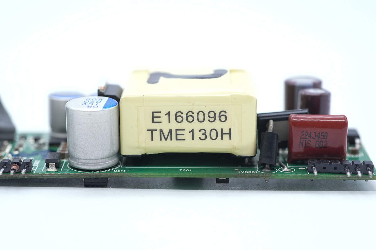
The transformer core is wrapped with insulating tape.
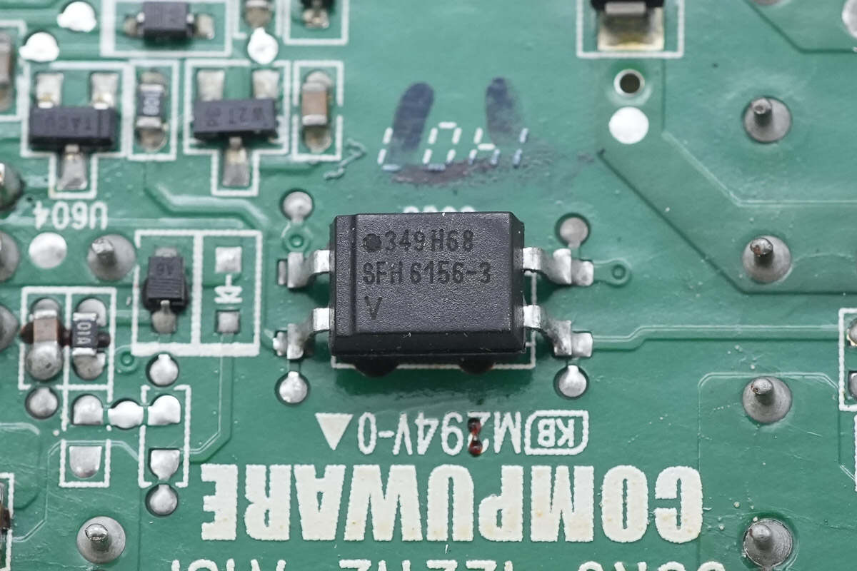
The optocoupler is used for output voltage feedback.
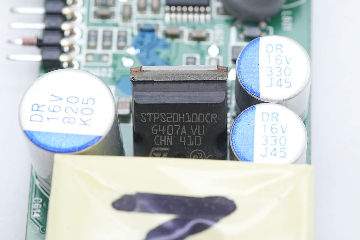
The rectifier is from STMicroelectronics, model STPS20H100CR. It is a Schottky diode rated at 100V, 20A, housed in a TO-220AB package.

The solid capacitor is rated at 820μF, 16V.
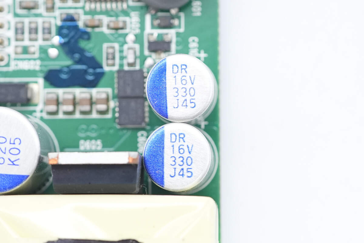
Both of these filter solid-state capacitors are rated at 330μF, 16V.
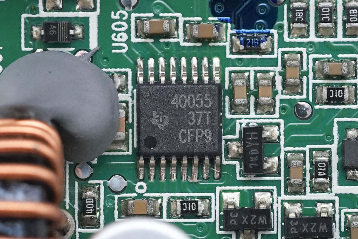
The synchronous buck controller is from Texas Instruments, model TPS40055. It features a wide input voltage range, supports switching frequencies up to 1MHz, and comes in a 10-pin HTSSOP package.
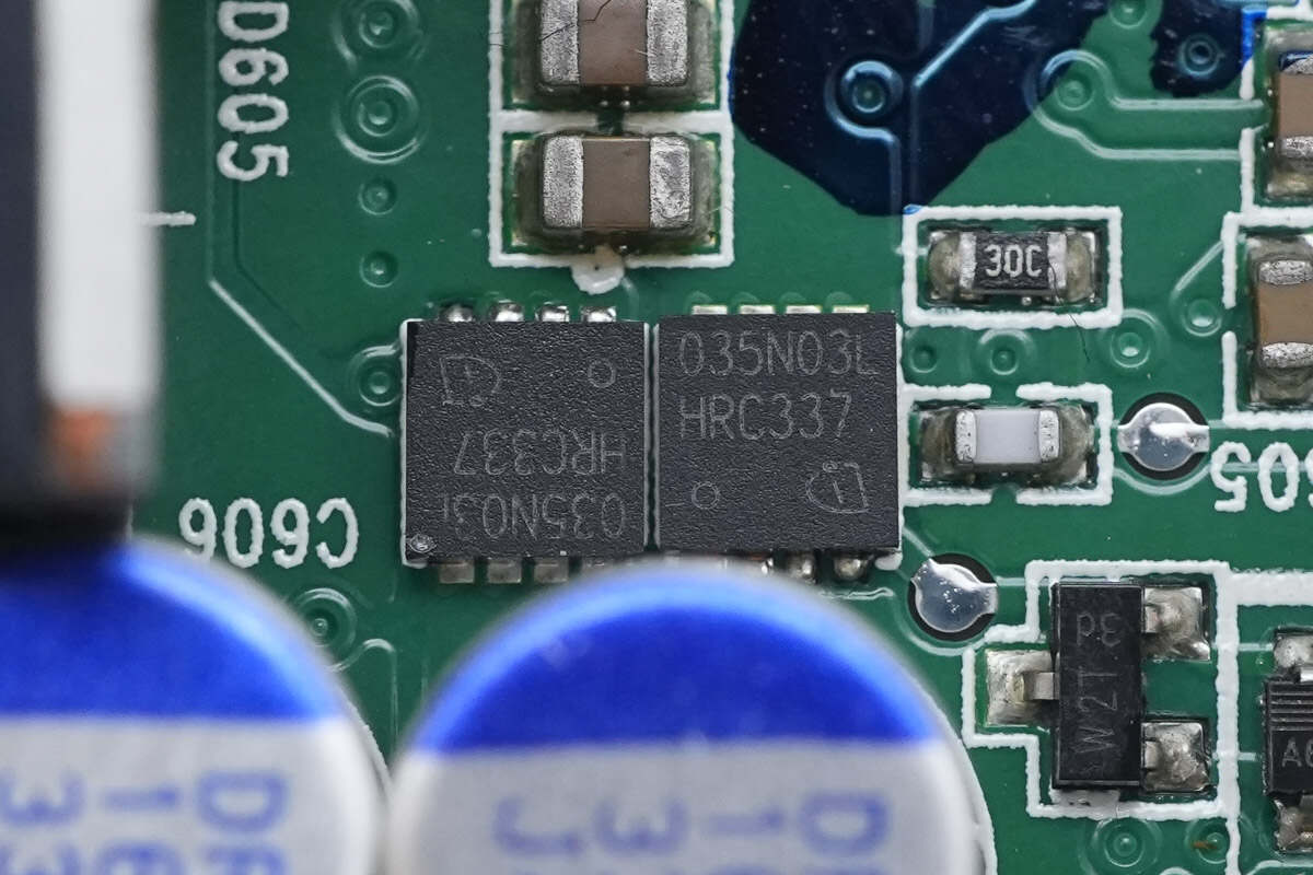
The synchronous buck MOSFETs are from Infineon, model BSZ035N03LS G. They are NMOS devices with a 30V rating, 3.5mΩ on-resistance, and come in an 8-pin TSDSON package.
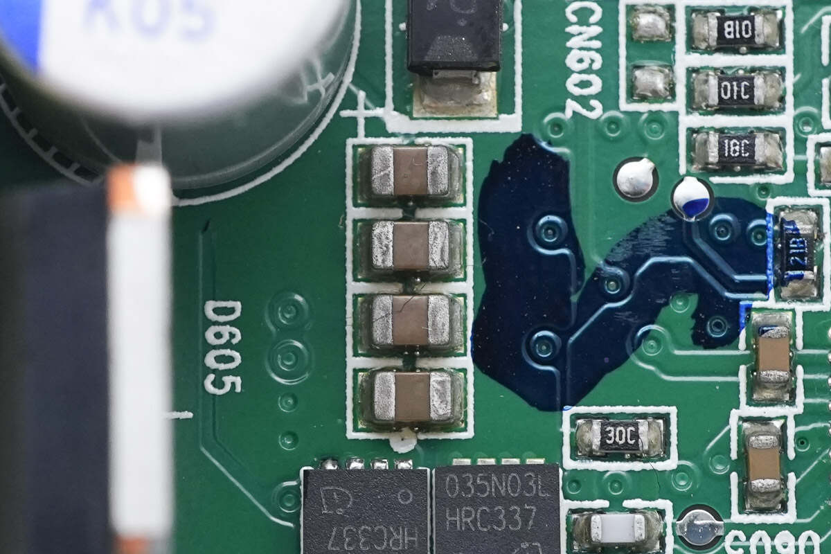
The MLCC capacitors are connected in parallel for input filtering.
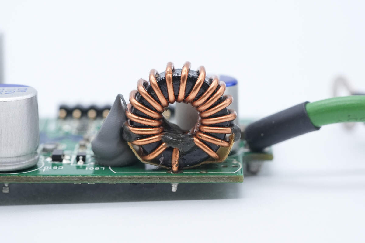
The buck inductor is wound using a toroidal core.
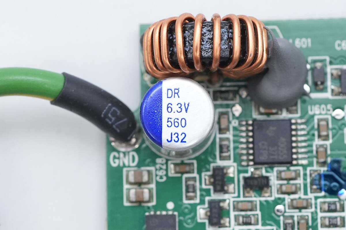
The output filter solid capacitor is rated at 560μF, 6.3V.
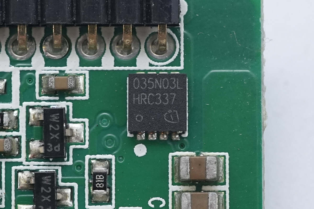
The output control MOSFET is also an Infineon BSZ035N03LS G.
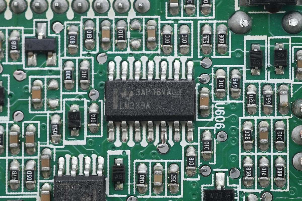
On the back side is an LM339A quad voltage comparator.
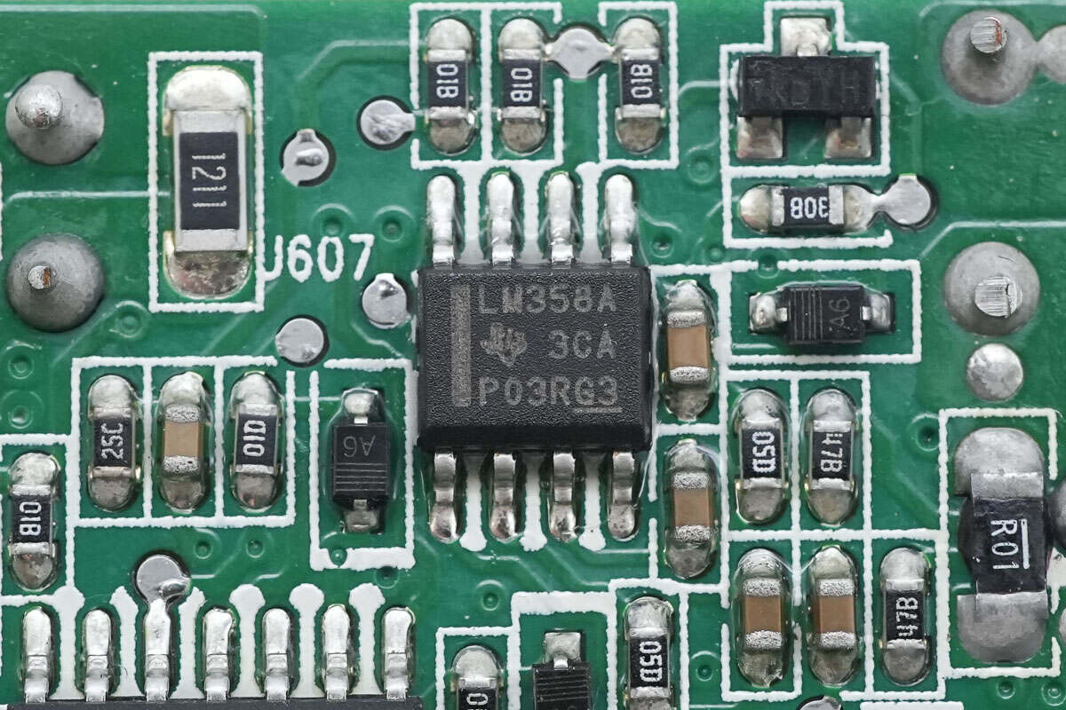
The back side is equipped with an LM358A dual op-amp.
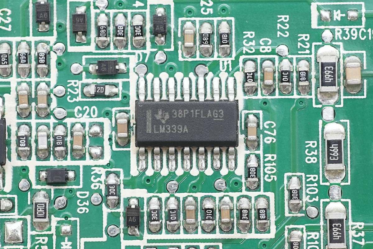
Close-up of the LM339A quad voltage comparator.
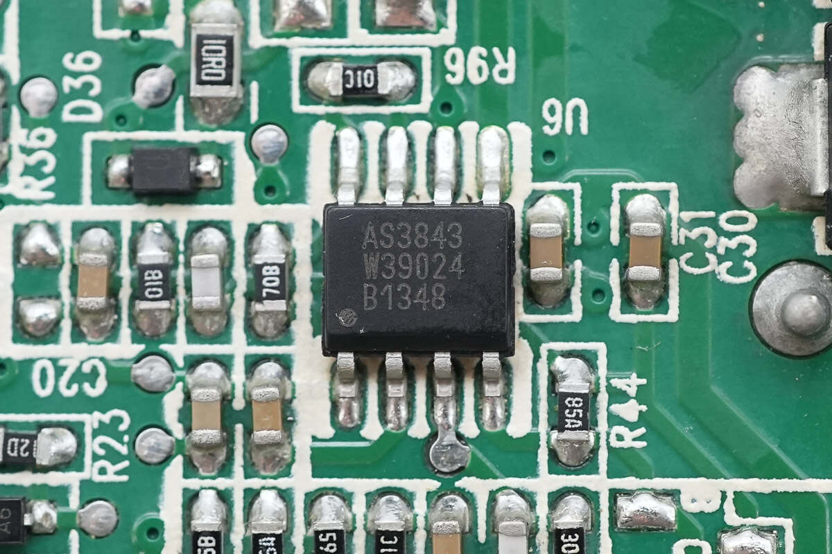
Close-up of the AS3843 PWM controller.
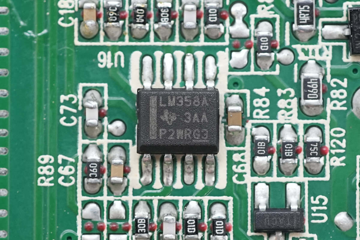
Close-up of the LM358A dual op-amp.
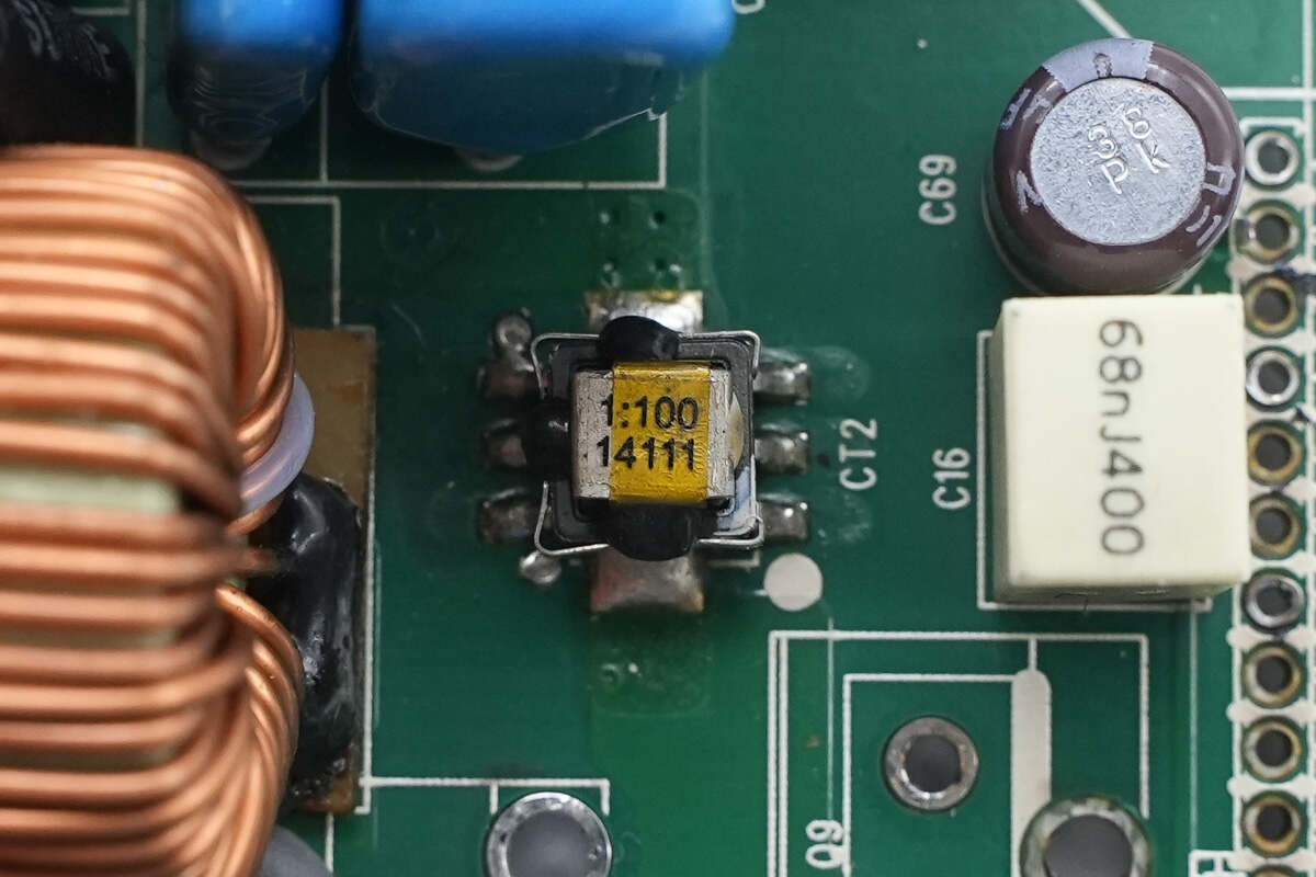
Close-up of the current transformer.
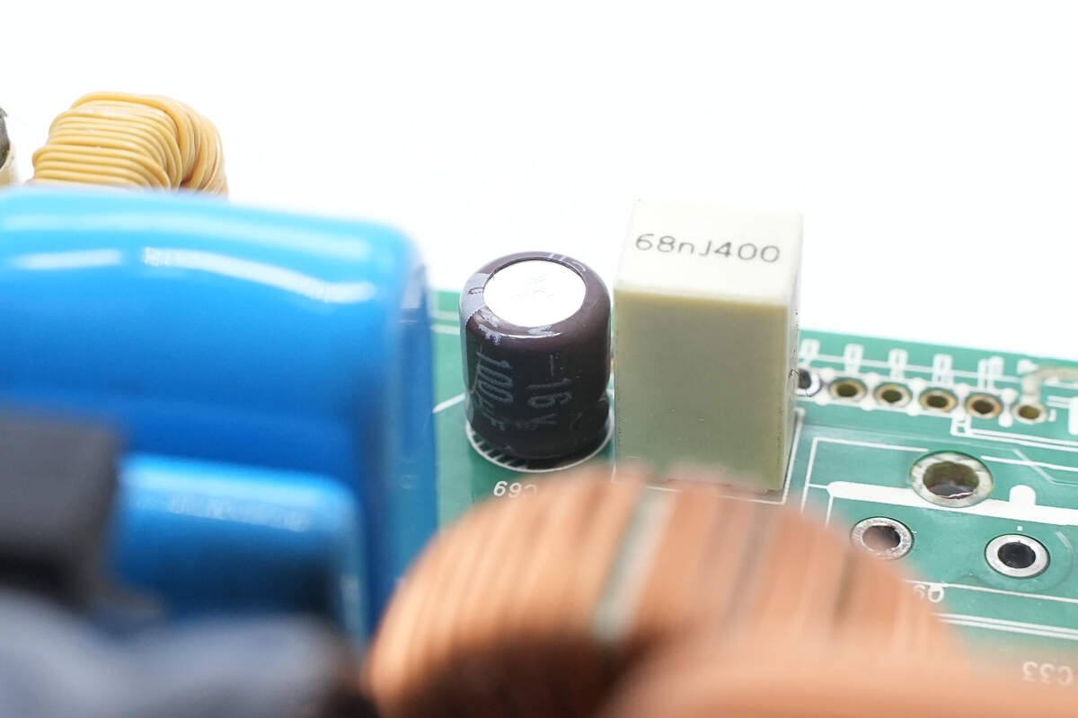
The electrolytic capacitor is from NCC, rated at 100μF, 16V.
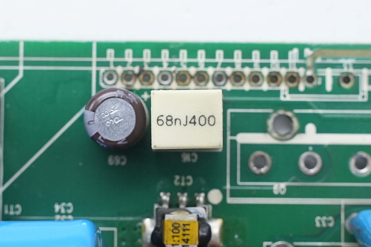
The film capacitor is rated at 68nF, 400V.
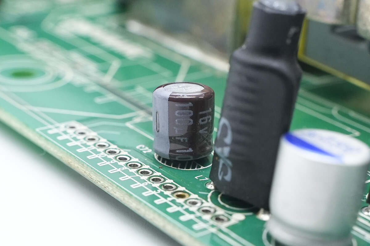
Another filter electrolytic capacitor with the same specifications.
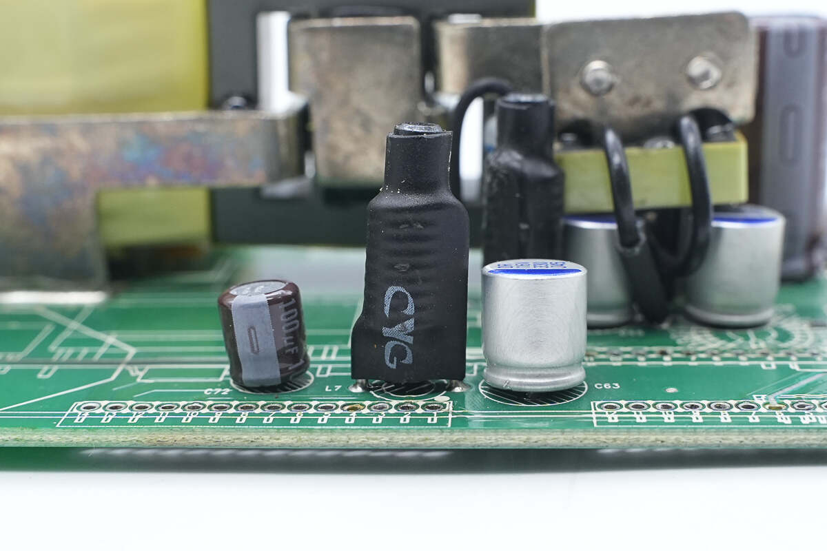
The filter inductor is insulated with heat shrink tubing.
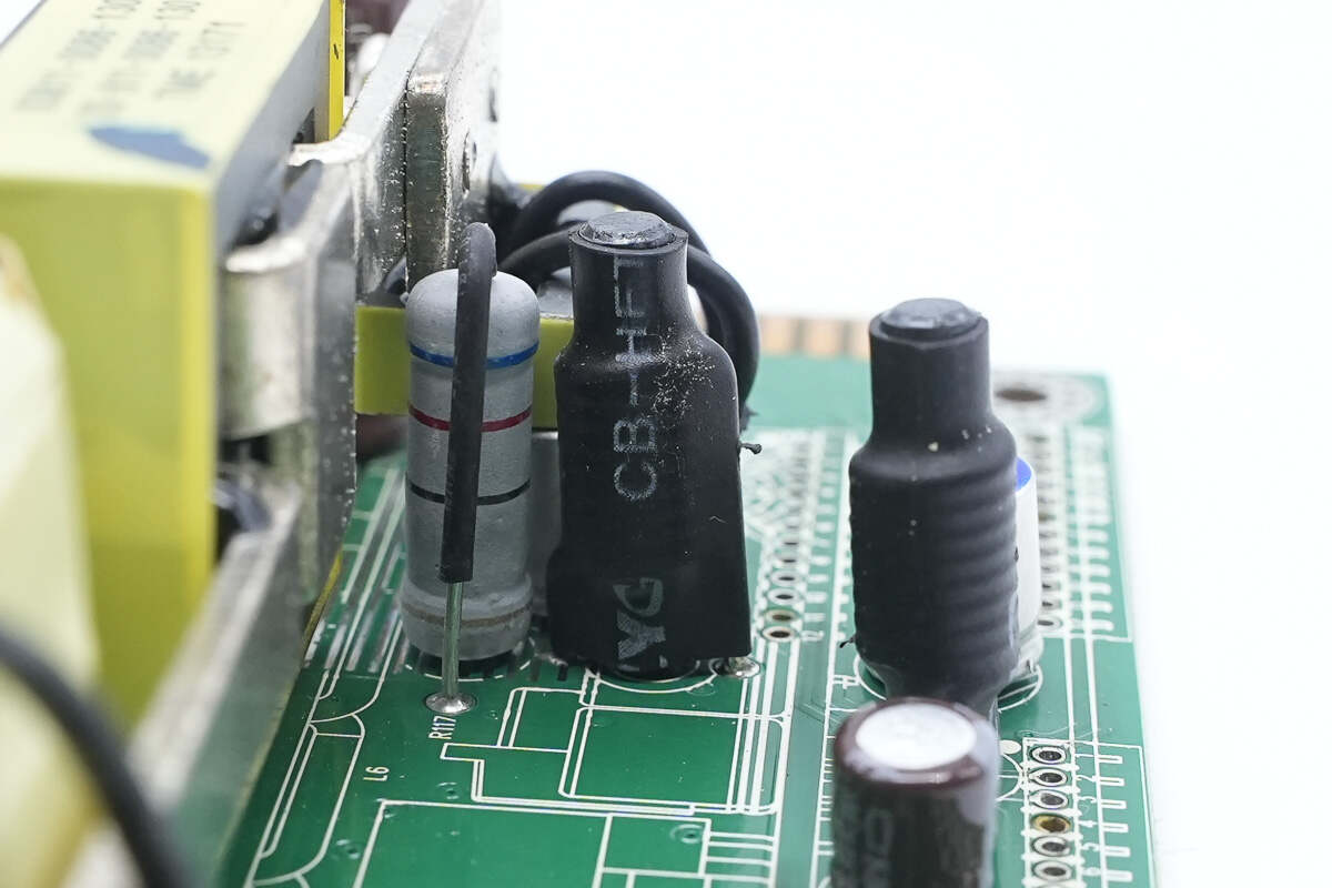
The other filter inductor is also insulated with heat shrink tubing.
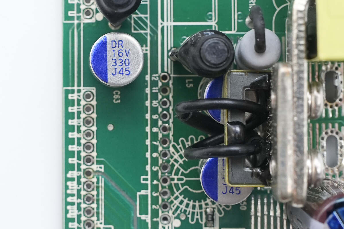
All three solid-state capacitors are rated at 330μF, 16V.
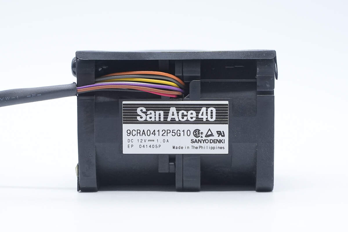
The cooling fan is from SANYO DENKI, model 9CRA0412P5G10, rated at 12V 1A, manufactured in the Philippines.
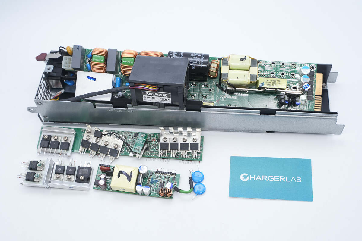
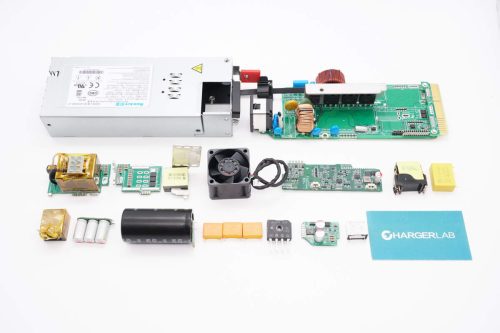
Well, those are all components of the Supermicro 720W 1U Redundant Power Supply.
Summary of ChargerLAB
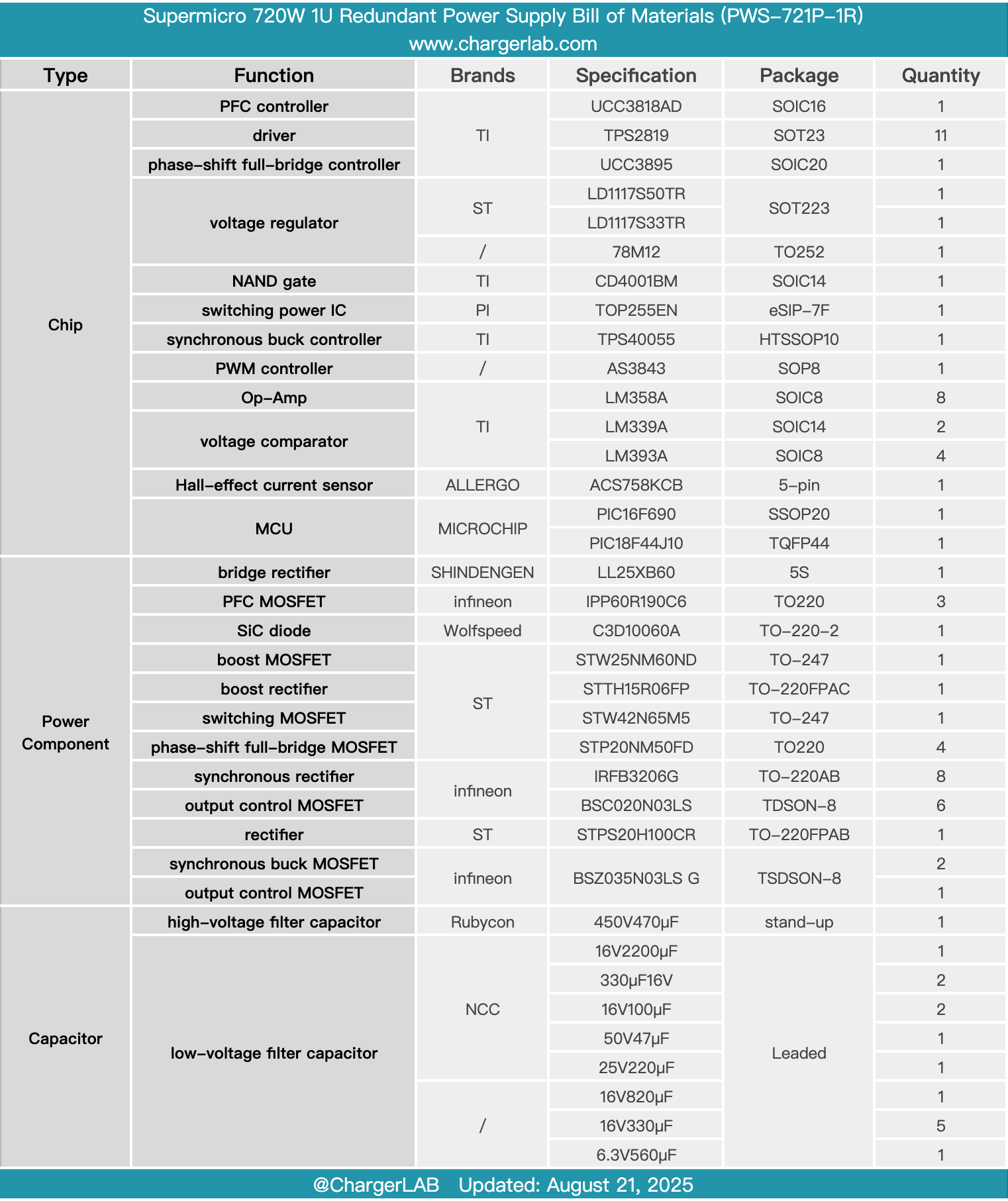
Here is the component list of the Supermicro 720W 1U Redundant Power Supply for your convenience.
It supports a wide input voltage range of 100-240V, with a rated output power of 720W and a 12V output voltage, along with a 5V standby output. The input side features a C14 power socket, a cooling fan, an LED indicator, and a handle. The output side has a gold finger connector for hot-swapping.
After taking it apart, we found it uses a PFC plus phase-shift full-bridge architecture. The PFC controller is the TI UCC3818AD, paired with Infineon IPP60R190C6 MOSFETs and Wolfspeed C3D10060A silicon carbide diode. The phase-shift full-bridge controller is the TI UCC3895, utilizing STMicro STP20NM50FD MOSFETs.
Inside, there is a control PCB and a standby power PCB. The control PCB features a Microchip MCU for parameter monitoring and communication functions. The standby power PCB uses a PI TOP255EN power chip, and the output current is monitored via a Hall current sensor. The internal layout is compact, with solid and reliable build quality and component selection.
Related Articles:
1. Teardown of UGREEN Nexode 20000mAh 165W Power Bank with Retractable USB-C Cable (PB726)
2. Teardown of Walmart Onn. 72W Multi-Port GaN Wall Charger (WIAWHT36008513)
3. Teardown of HUNDA 300W USB-C GaN Charging Station (A2319-300W-02)

