Introduction
Skyworth recently launched a new fast-charging product—the Skyworth 140W Smart Display Charger. It features four ports in total, including three USB-C ports and one USB-A port, with a maximum output of 140W supported by PD3.1, allowing for simultaneous charging of multiple devices.
The TFT color screen provides a comprehensive view, enabling real-time monitoring of power, temperature, time, and other data. With enhanced safety visibility, it offers users a more secure and reliable charging experience. Next, let’s take a closer look at its internal components and design.
Product Appearance
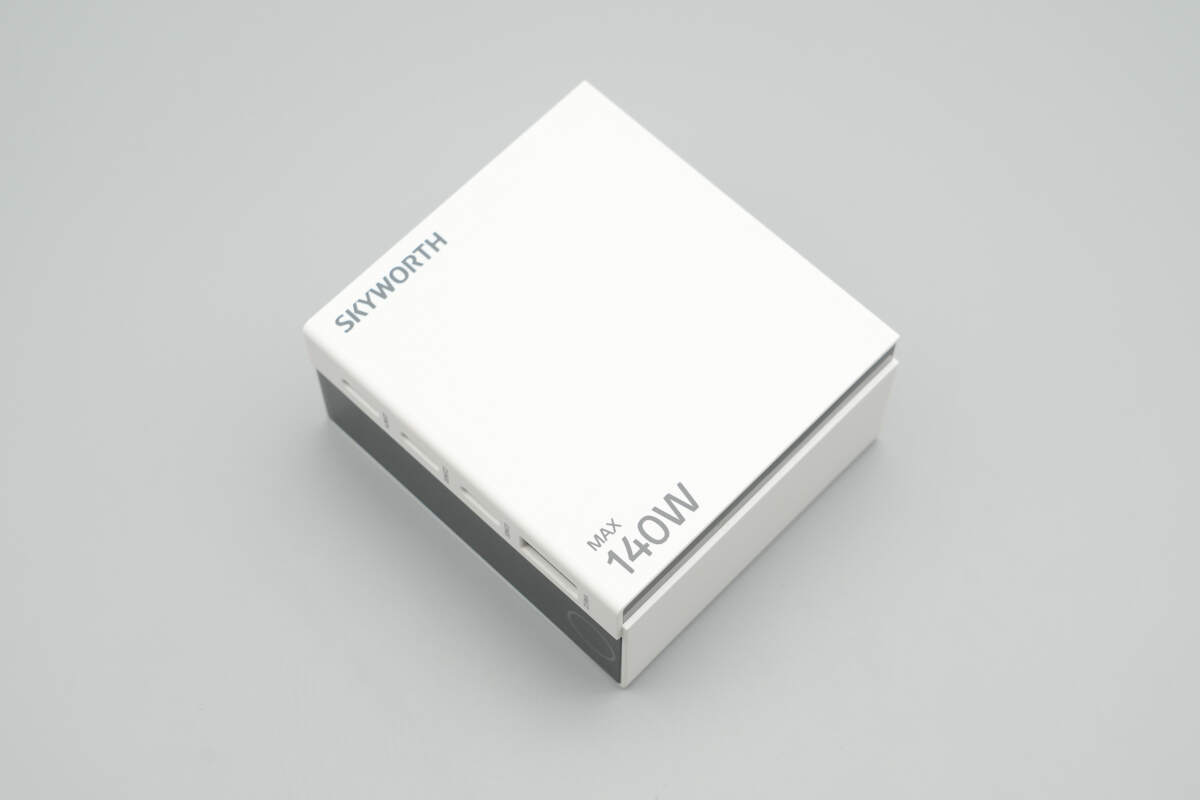
The shell is made of flame-retardant PC material and features a simple yet stylish black-and-white color scheme.

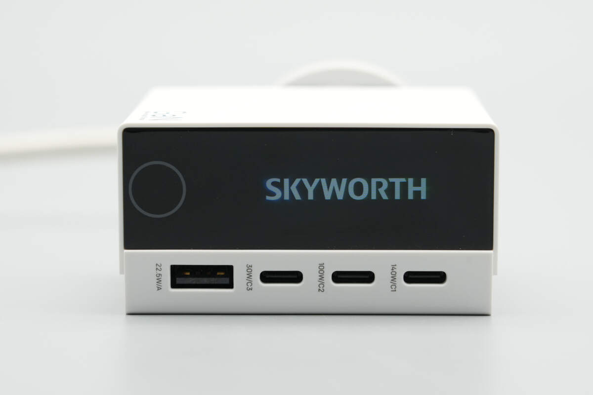
The front is printed with SKYWORTH and 140W MAX.
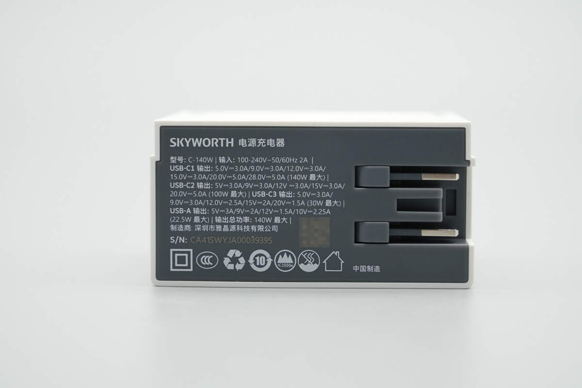
The input end is printed with parameter information.

Model: C-140W
Input: 100-240V~50/60Hz 2A
Output:
USB-C1: 5V3A, 9V3A, 12V3A, 15V3A, 20V5A, 28V5A (Max 140W)
USB-C2: 5V3A, 9V3A, 12V3A, 15V3A, 20V5A (Max 100W)
USB-C3: 5V3A, 9V3A, 12V2.5A, 15V2A, 20V1.5A (Max 30W)
USB-A: 5V3A, 9V2A, 12V1.5A, 10V2.25A (Max 22.5W)
Total Output Power: Max 140W
The product has passed CCC certification.
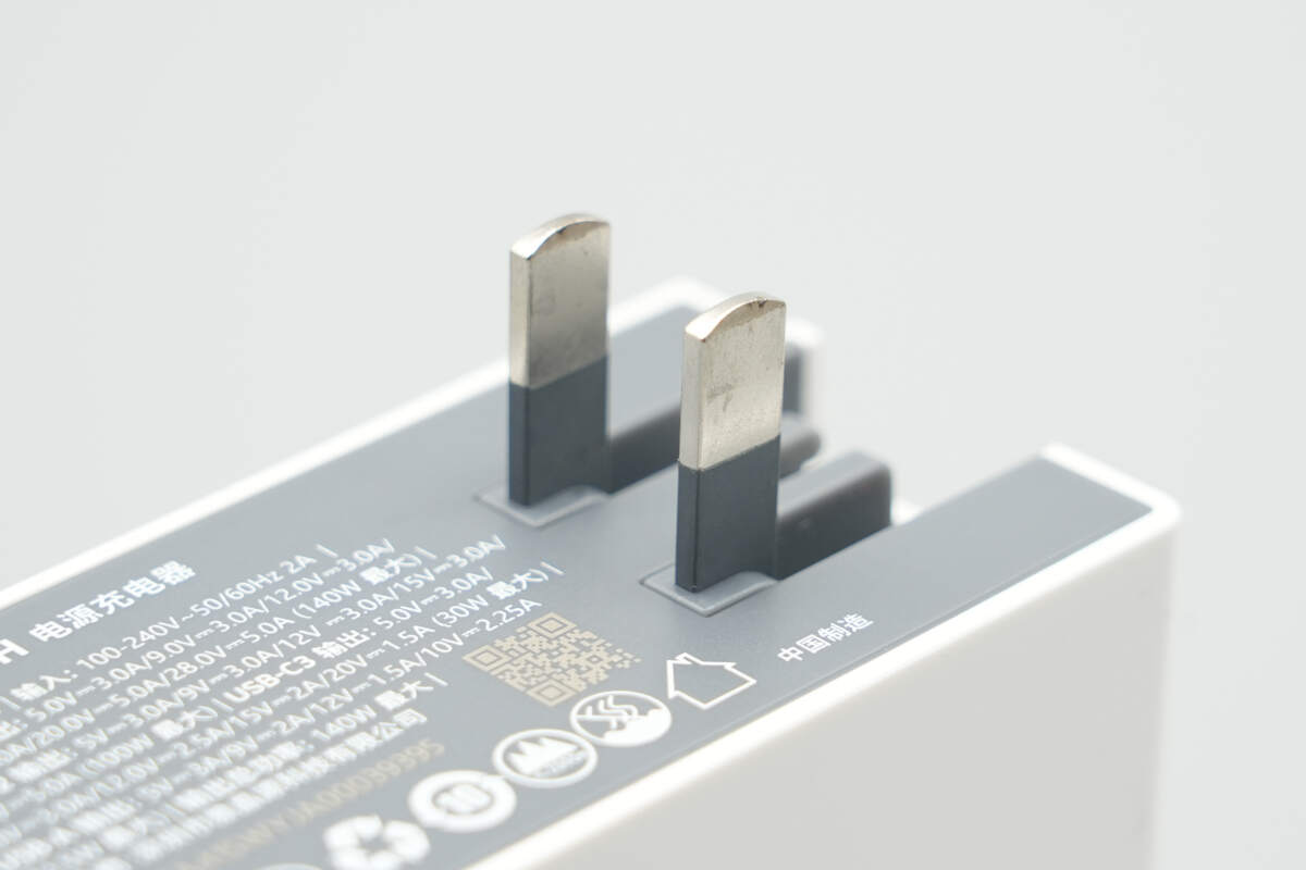
It is equipped with foldable prongs.
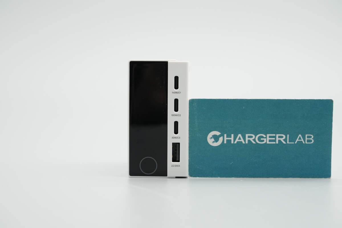
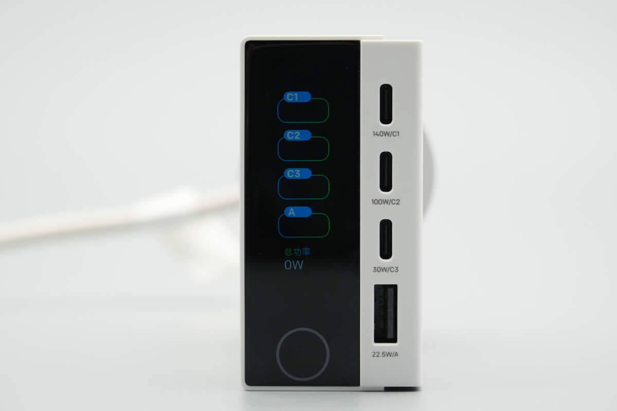
The left side features a TFT color display, while the right side is equipped with 3 USB-C ports and 1 USB-A port.
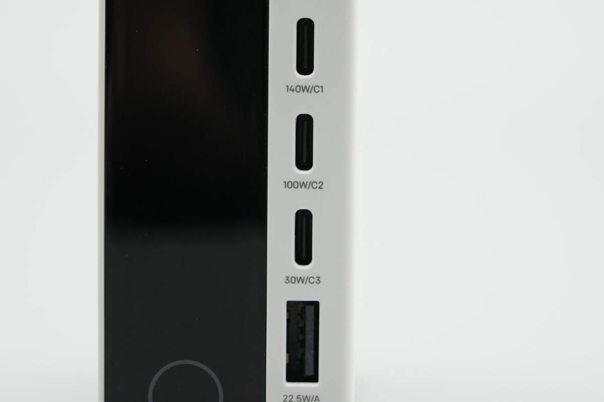
Each of the four ports is marked with its label and maximum output power.
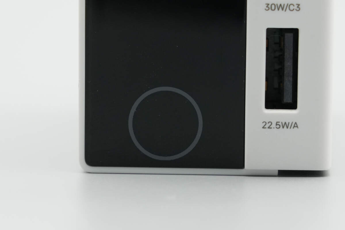
A touch control button is located below the screen, making operation simpler.
Close-up of the startup screen.
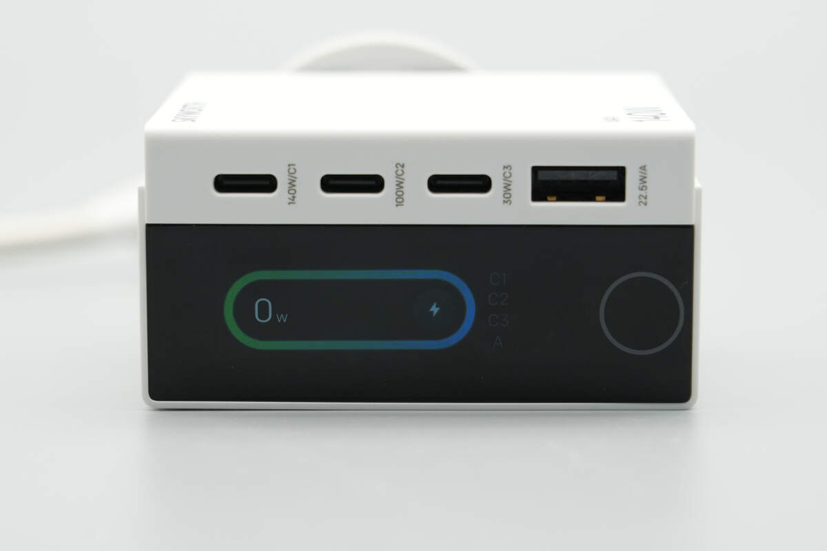
In the no-load state, the screen displays an output of 0W.
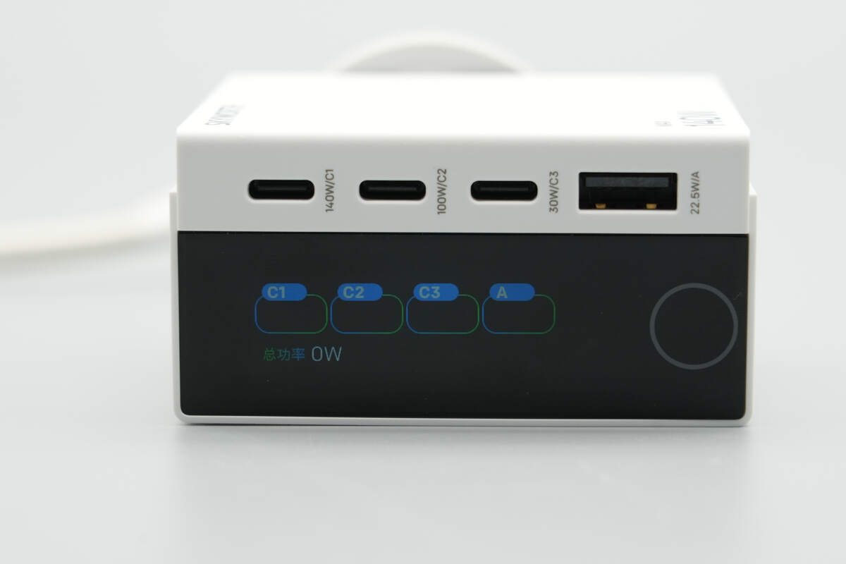
A single tap on the touch control button switches the interface. The power interface displays the usage status and output power of each port, and the total power.
A long press of the touch control button for 5 seconds allows the screen to switch between landscape and portrait modes.
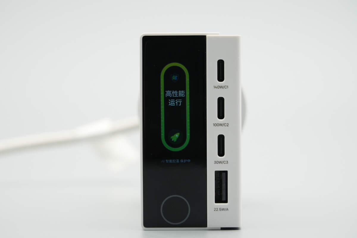
Close-up of the temperature interface.
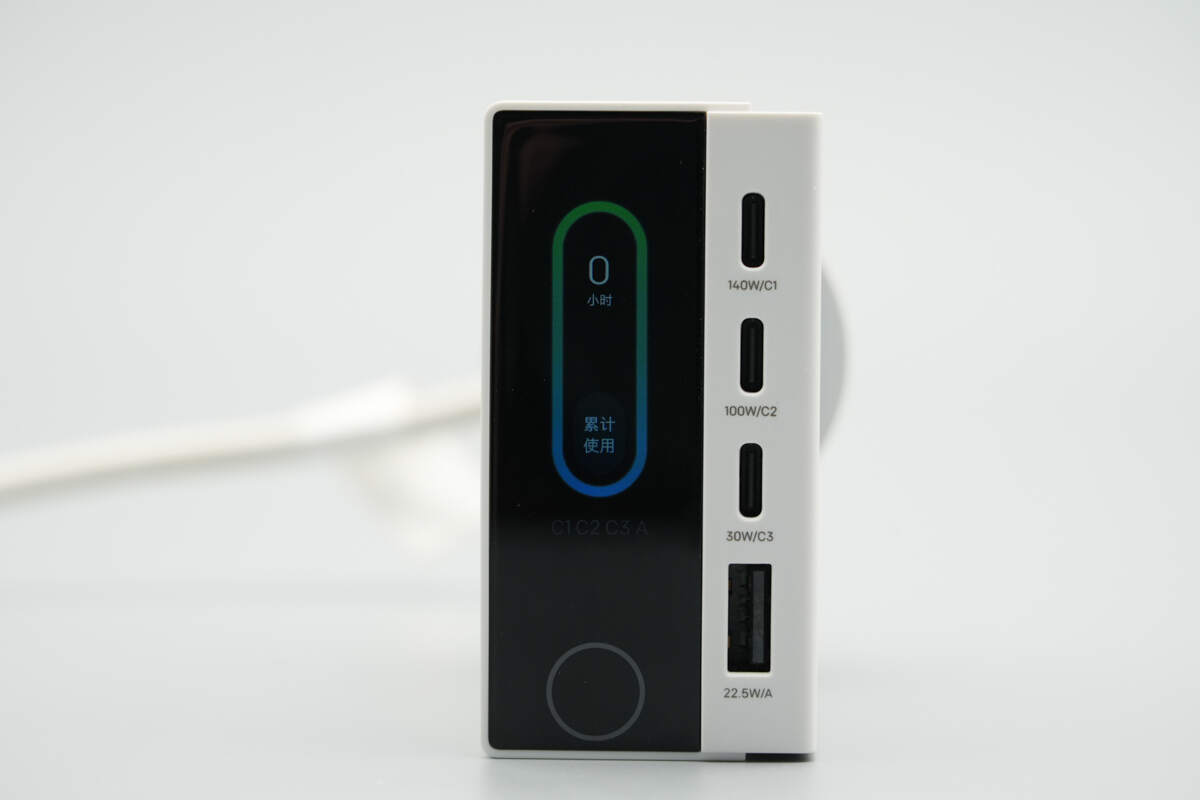
Close-up of the accumulated time interface.
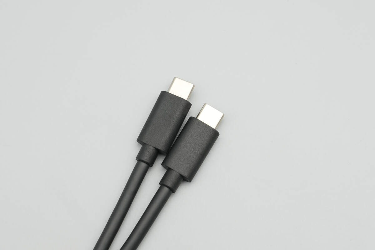
The included cable is of the USB-C to USB-C type.

The length of the cable is about 152 cm (59.84 inches).

ChargerLAB POWER-Z KM003C shows it has an E-Marker chip. Its power transmission capability is 50V 5A, and its data transmission capability is USB 2.0.
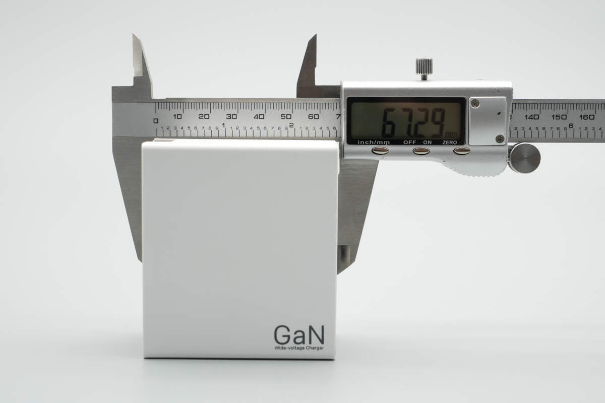
The length of the charger is about 67.29 mm (2.65 inches).
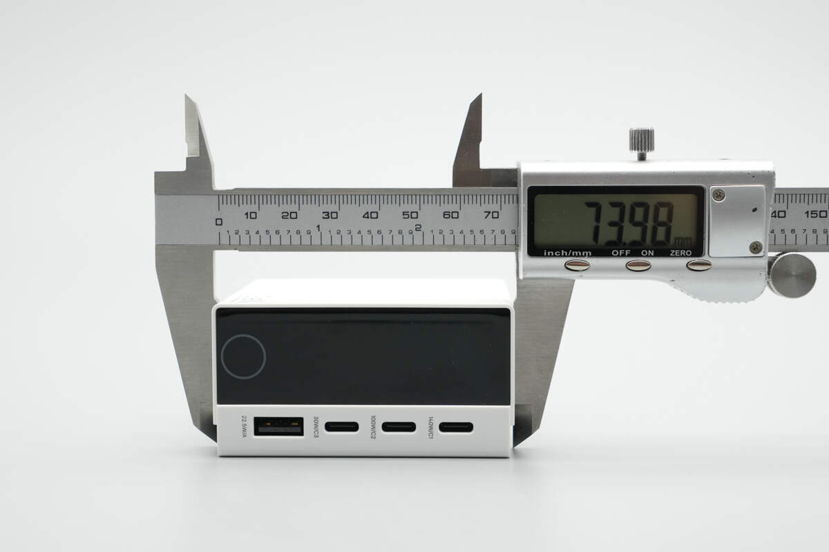
The width is about 73.98 mm (2.91 inches).
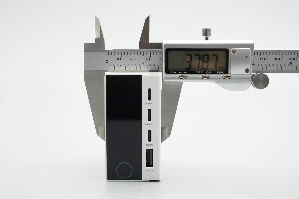
The thickness is about 37.87 mm (1.49 inches).
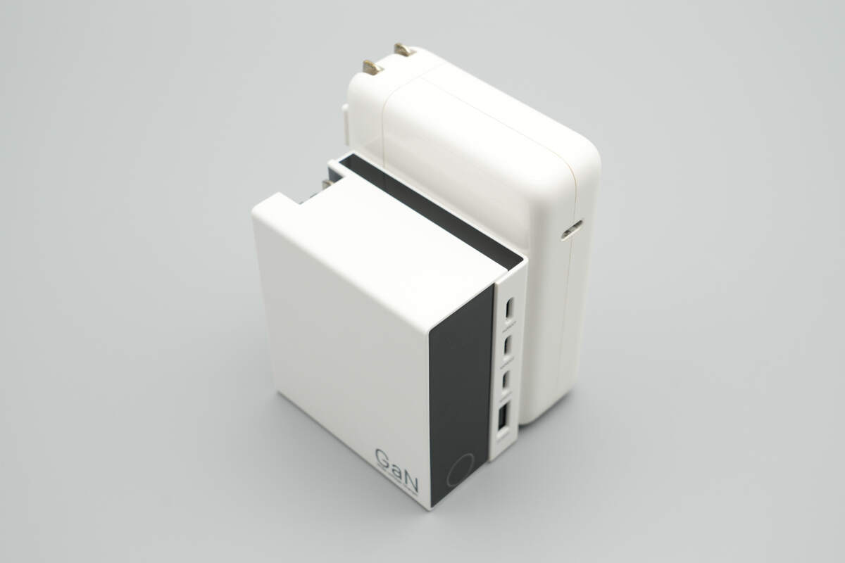
An overview comparing it with the Apple 140W GaN charger.
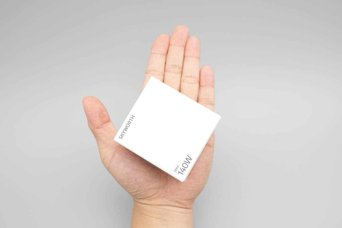
That's how big it is in the hand.
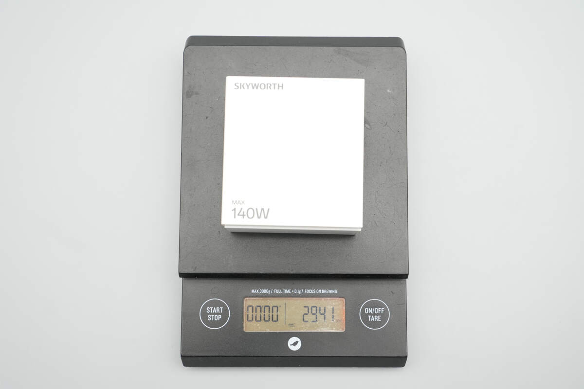
The weight is about 294 g (10.37 oz).
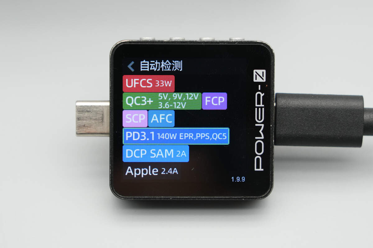
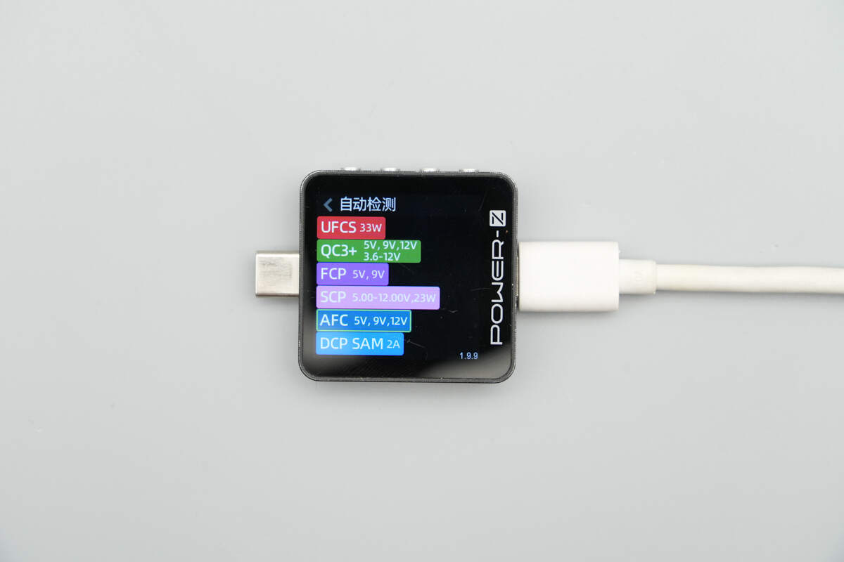
ChargerLAB POWER-Z KM003C shows that the USB-C1 supports UFCS, QC3+/5, FCP, SCP, AFC, PD3.1, PPS, DCP, SAM 2A, and Apple 2.4A charging protocols.
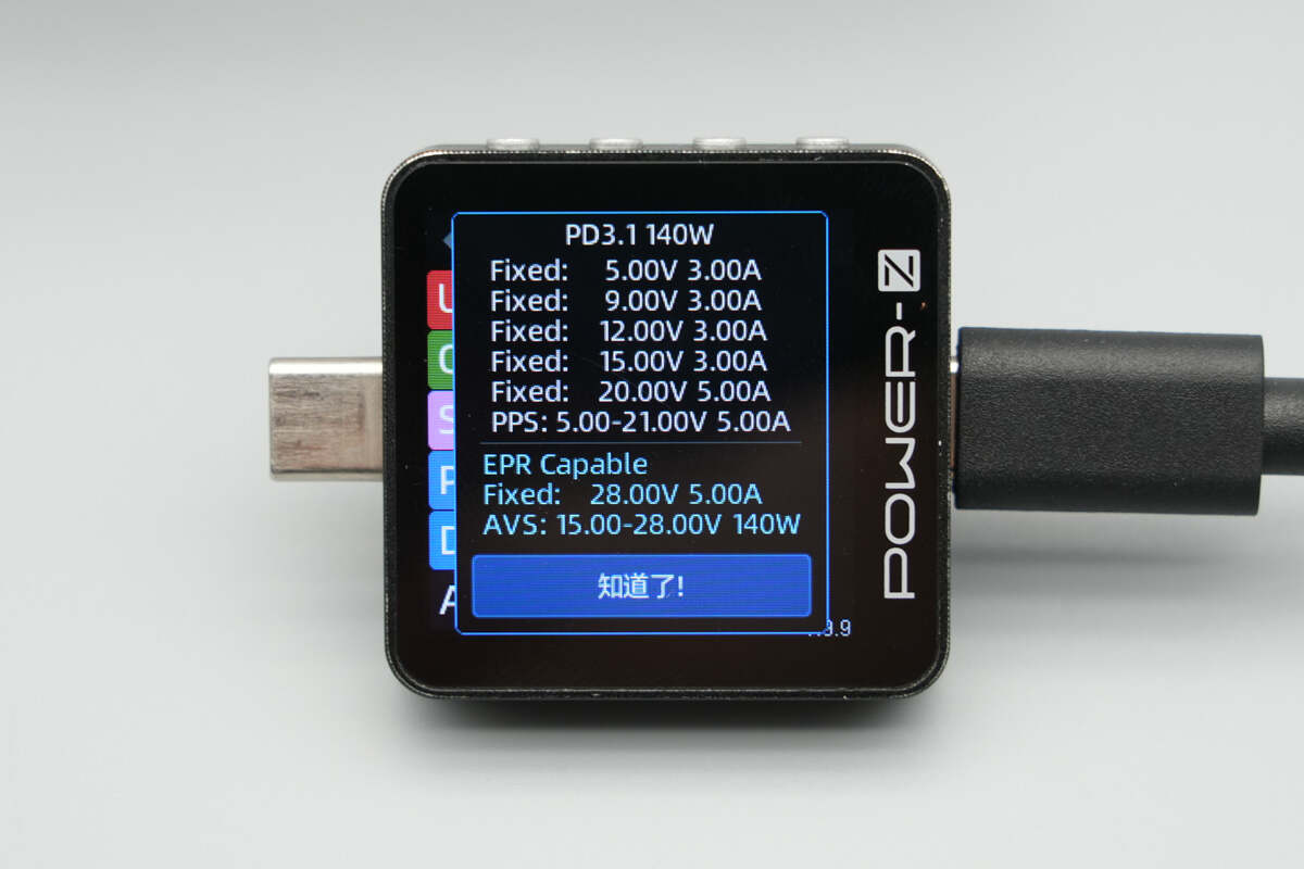
It has six fixed PDOs of 5V3A, 9V3A, 12V3A, 15V3A, 20V5A, and 28V5A, as well as one PPS voltage level of 5-21V5A and a 15-28V 140W AVS voltage level.
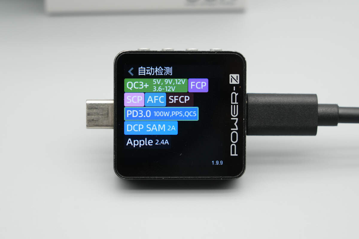
The USB-C2 supports QC3+/5, FCP, SCP, AFC, SFCP, PD3.0, PPS, DCP, SAM 2A, and Apple 2.4A protocols.
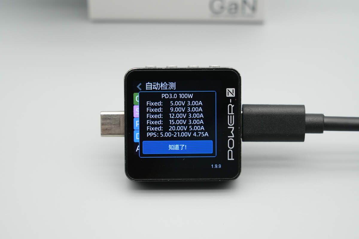
It has five fixed PDOs of 5V3A, 9V3A, 12V3A, 15V3A, and 20V5A. It also has one set of PPS, which is 5-21V4.75A.
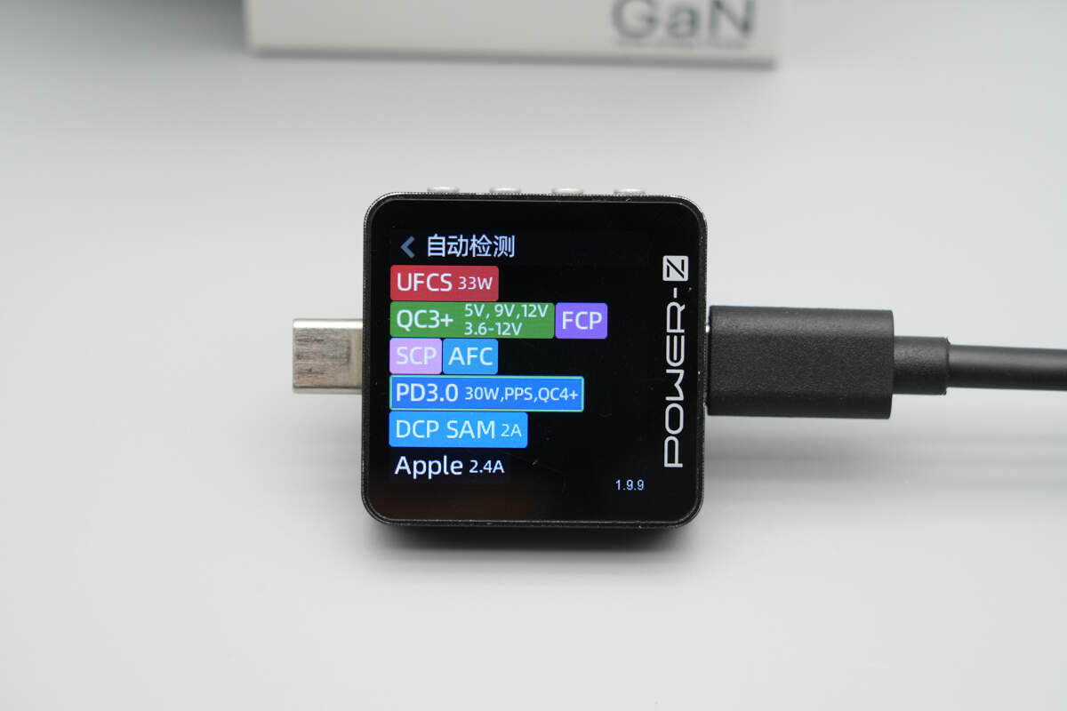
The USB-C3 supports UFCS, QC3+/4+, FCP, SCP, AFC, PD3.0, PPS, DCP, SAM 2A, and Apple 2.4A protocols.
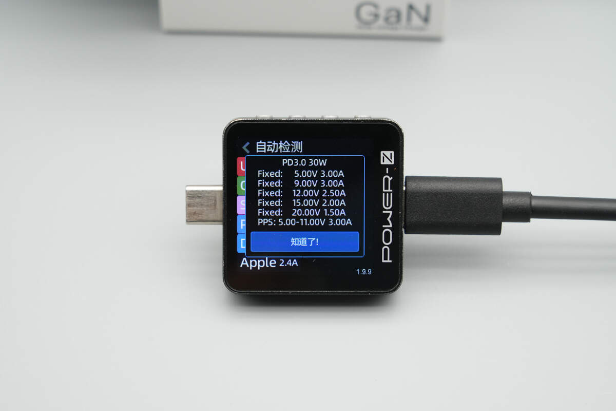
It has five fixed PDOs of 5V3A, 9V3A, 12V2.5A, 15V2A, and 20V1.5A. It also has one set of PPS, which is 5-11V3A.
The USB-A supports UFCS, QC3+, FCP, SCP, AFC, DCP, SAM 2A, and Apple 2.4A protocols.
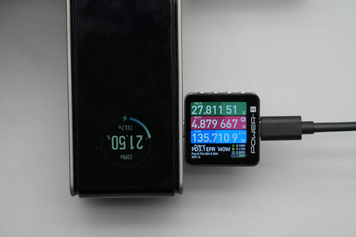
Using this charger to charge the EcoFlow 170W 25000mAh power bank, it successfully initiates 140W PD3.1 fast charging, with a charging power of about 135.71W.
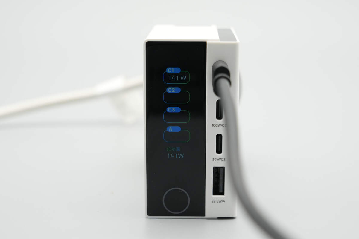
At this point, the power interface shows that the USB-C1 port is in use, with an output power of 141W.
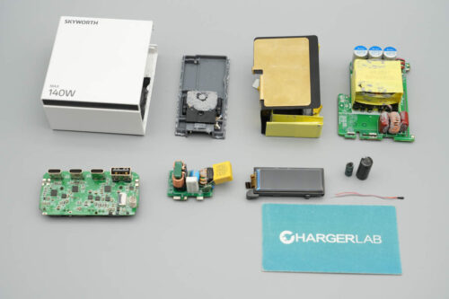
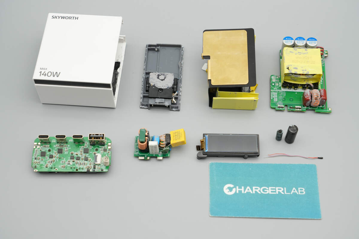
Teardown
Next, let's take it apart to see its internal components and structure.

Remove the input shell. The prongs are connected to the PCBA module via wires.
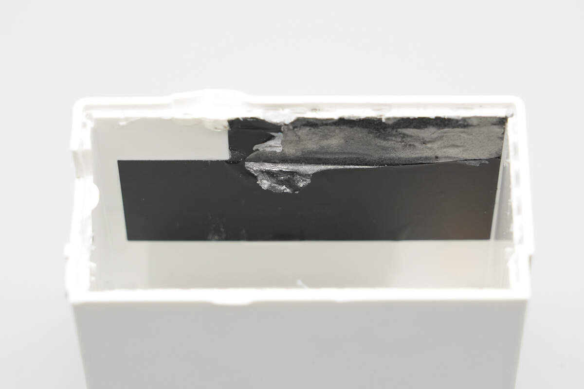
Remove the PCBA module. The interior of the shell is lined with a graphite thermal pad, along with insulation treatment.
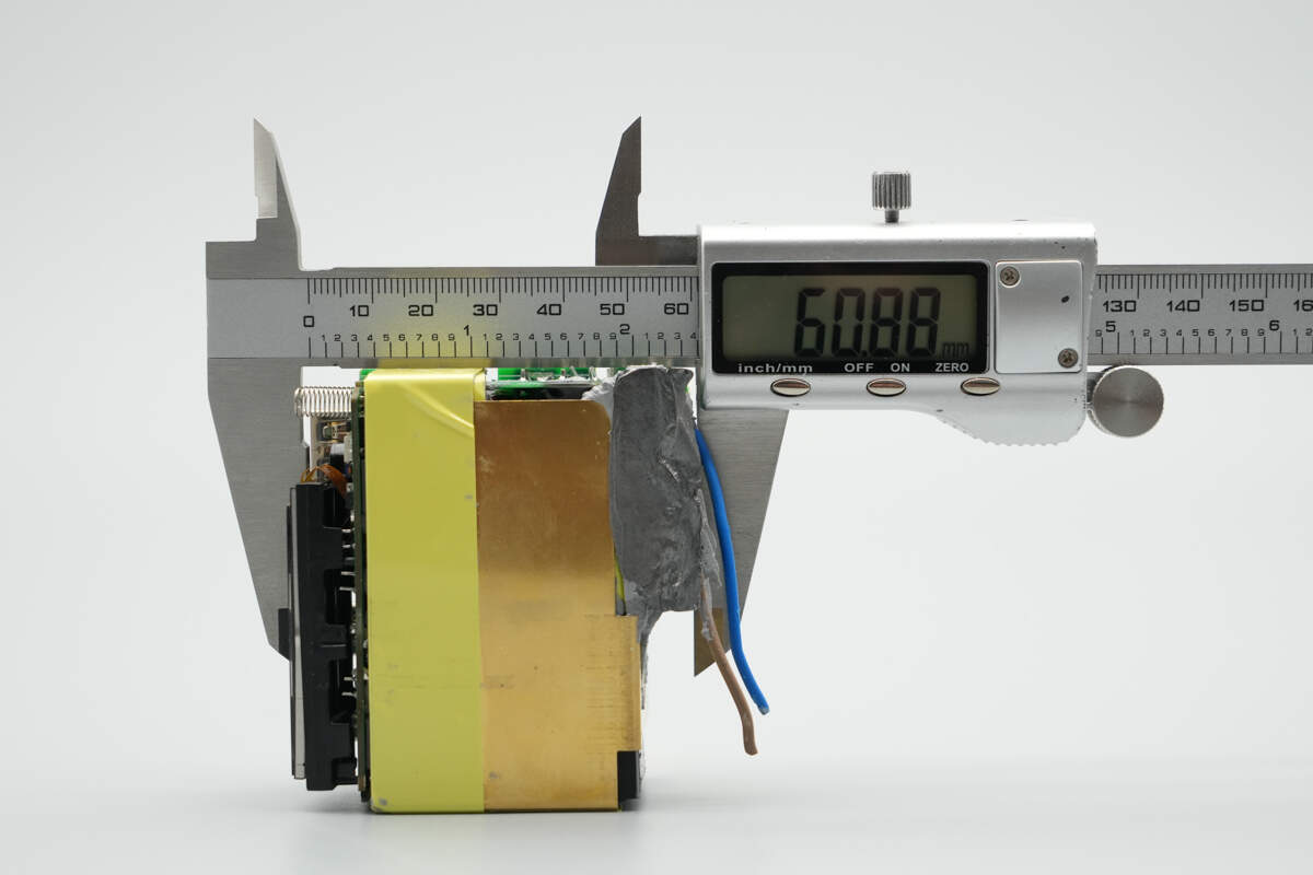
The length of the PCBA module is about 60.88 mm (2.4 inches).
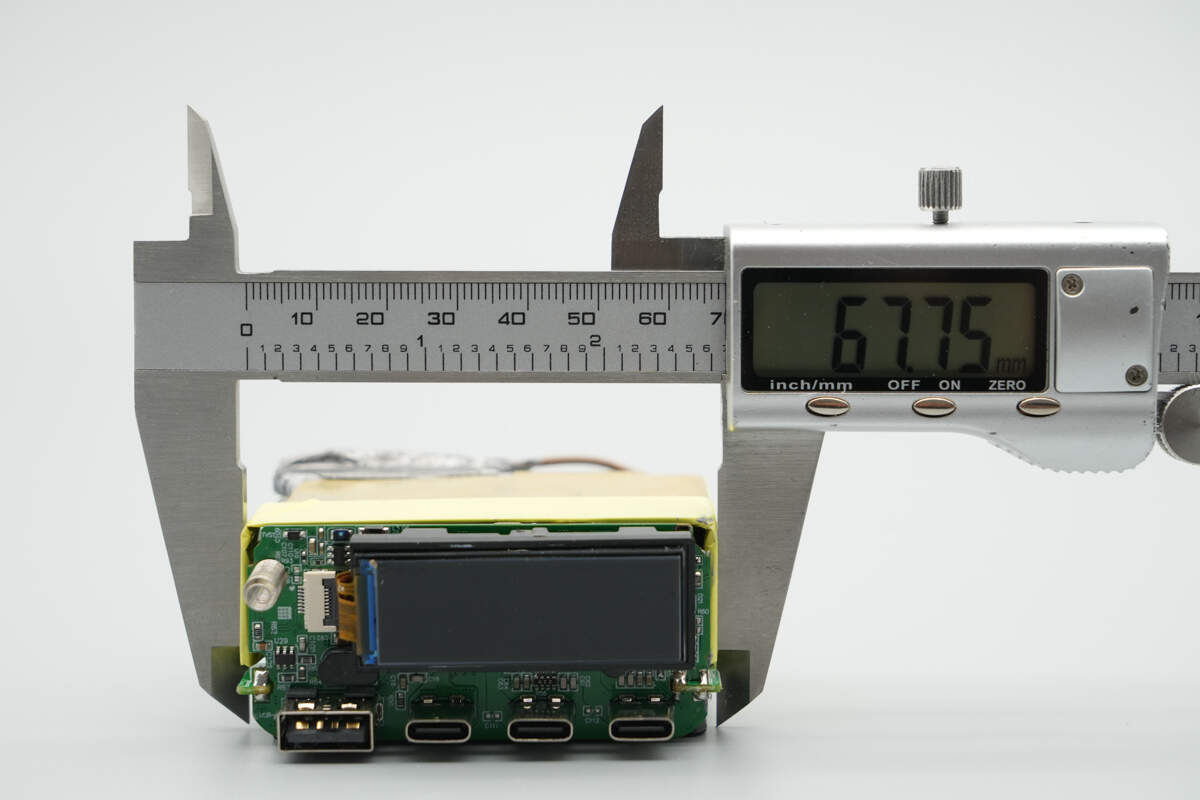
The width is about 67.75 mm (2.67 inches).

The thickness is about 31.67 mm (1.25 inches).

The PCBA module is covered with a copper heatsink. The secondary side is wrapped in insulating tape.

The bottom is isolated with a Mylar sheet for insulation.
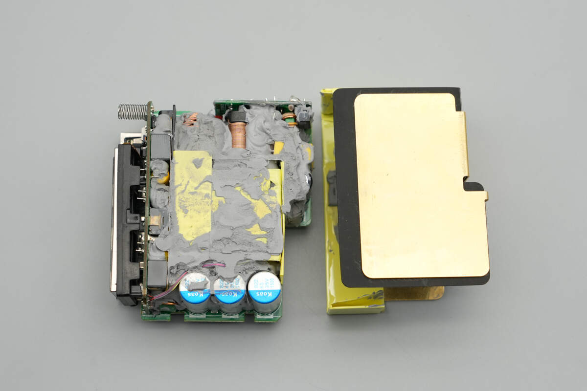
Remove the heatsink. The gaps between the components are filled with thermal adhesive to assist with heat dissipation.
Remove the thermal adhesive. The front of the module has a compact component layout, with small PCBs on one side and the output end. A plastic plate is also used for isolation and insulation between the primary and secondary sides.
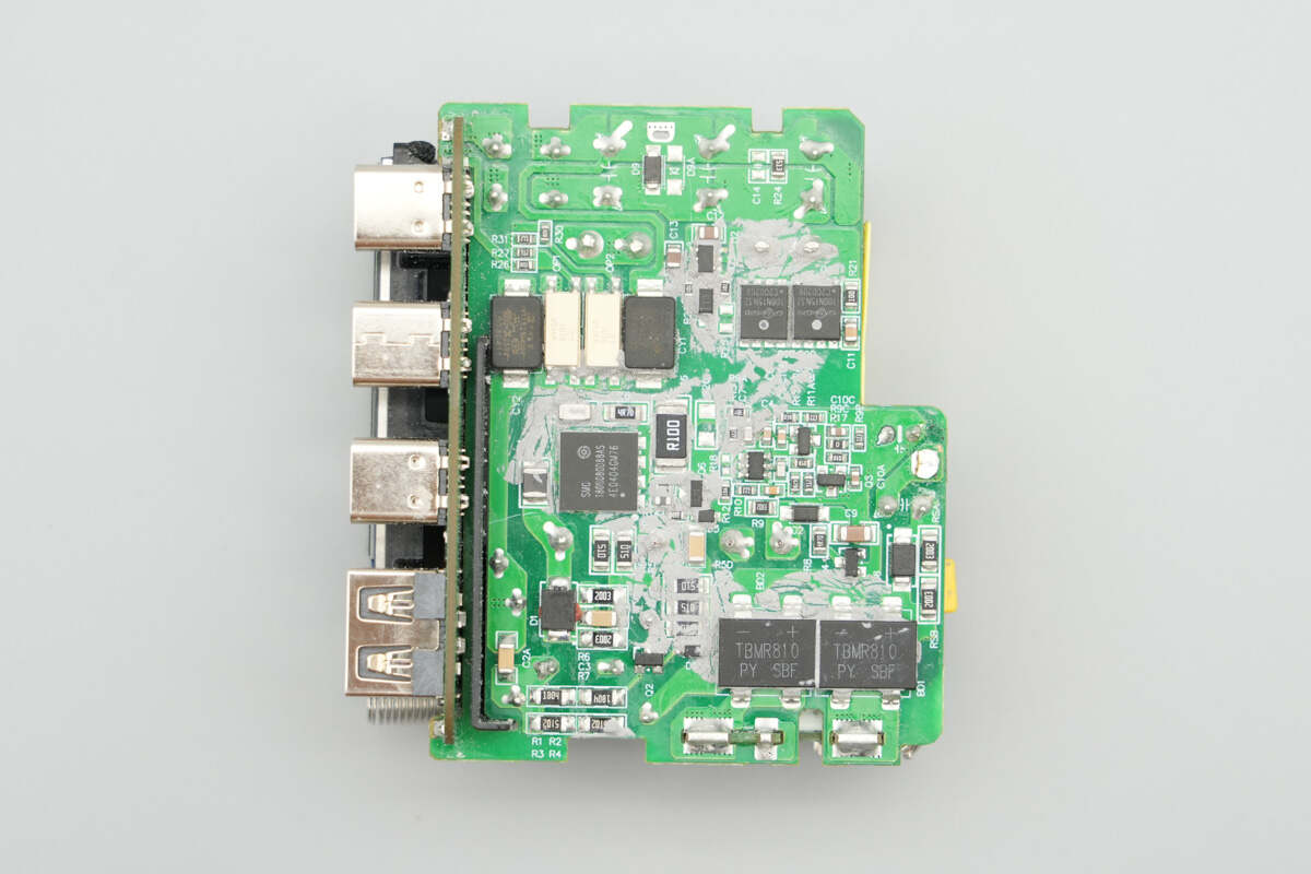
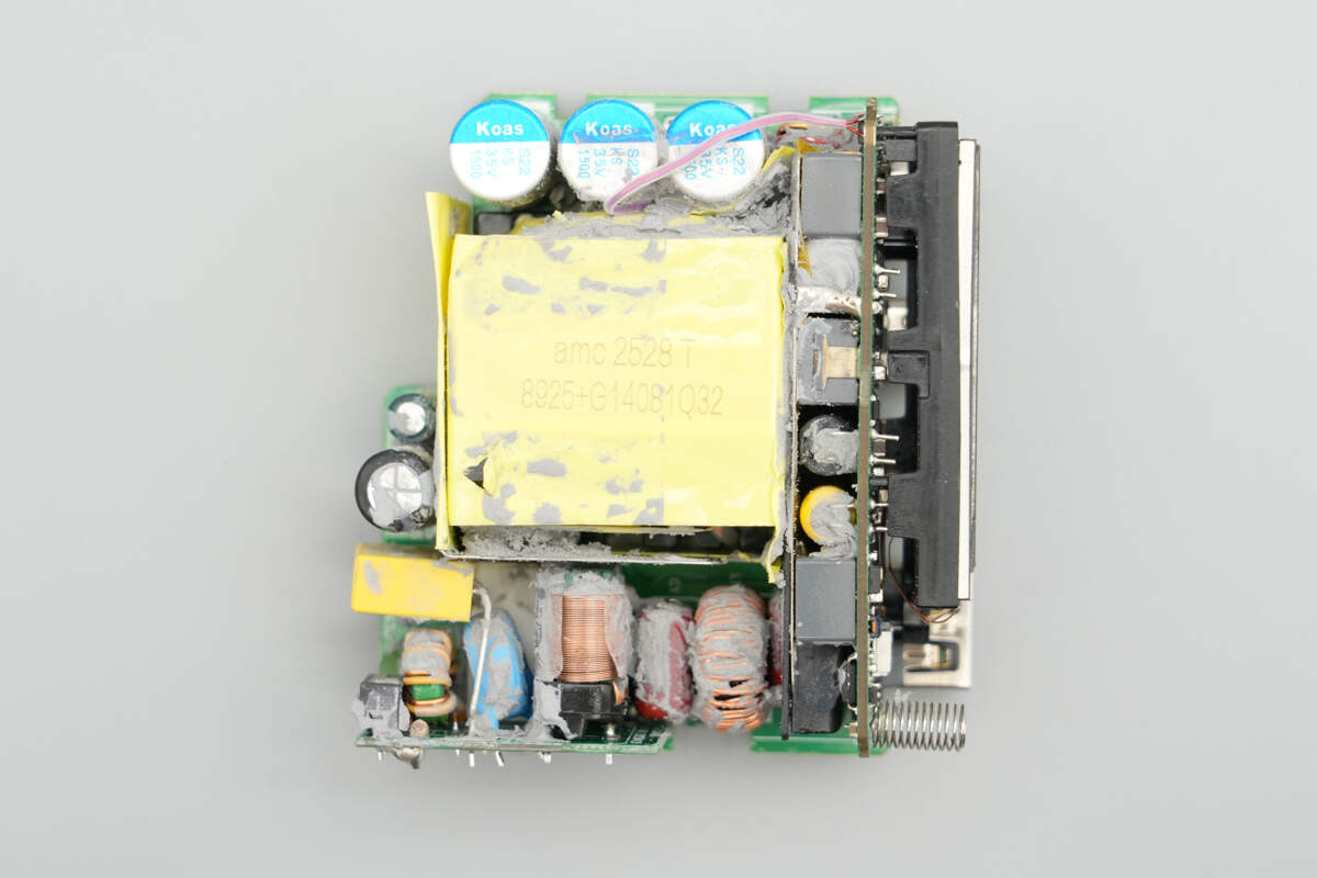
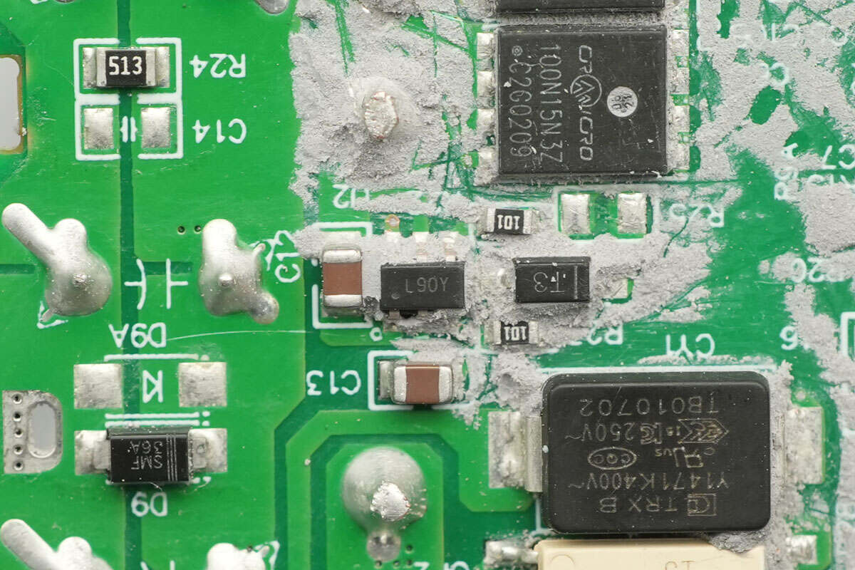
The back of the module features bridge rectifiers, the master control chip, primary MOSFETs, optocouplers, SMD Y capacitors, a synchronous rectifier controller, and synchronous rectifiers.
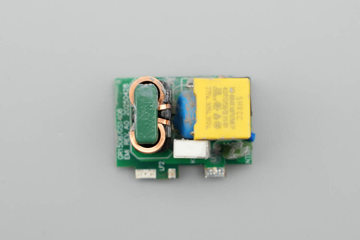
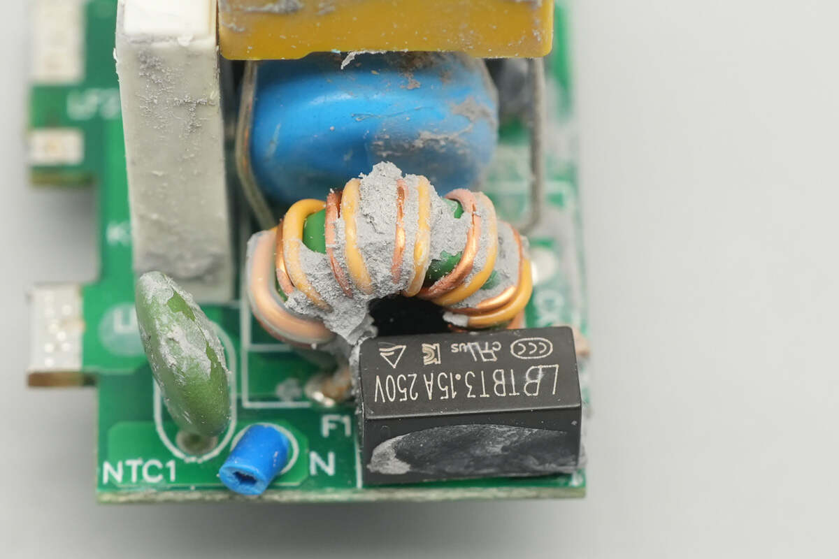
Remove the small PCB at the input end. The front of the PCB is equipped with a time-delay fuse, NTC thermistor, thermal protector, common mode chokes, safety X2 capacitor, and a varistor.
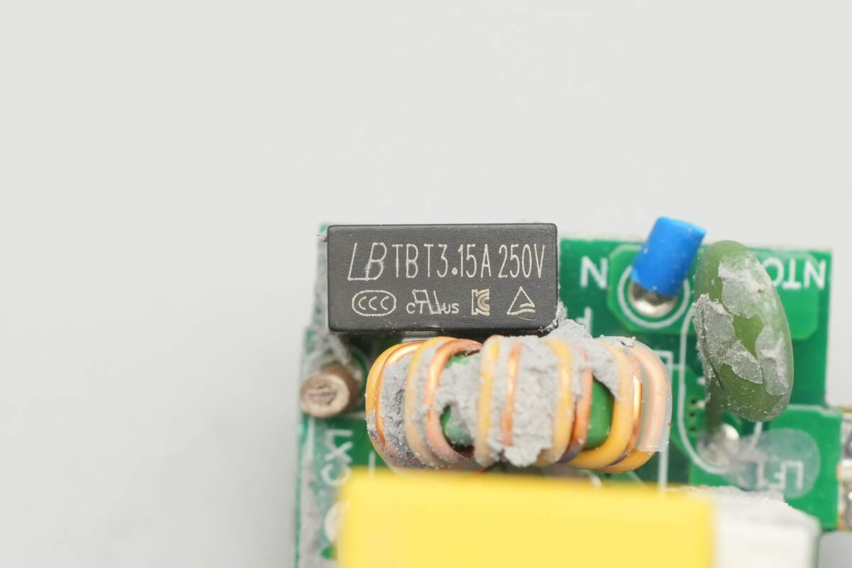
The time-delay fuse is from Lanbao, with a specification of 3.15A 250V.
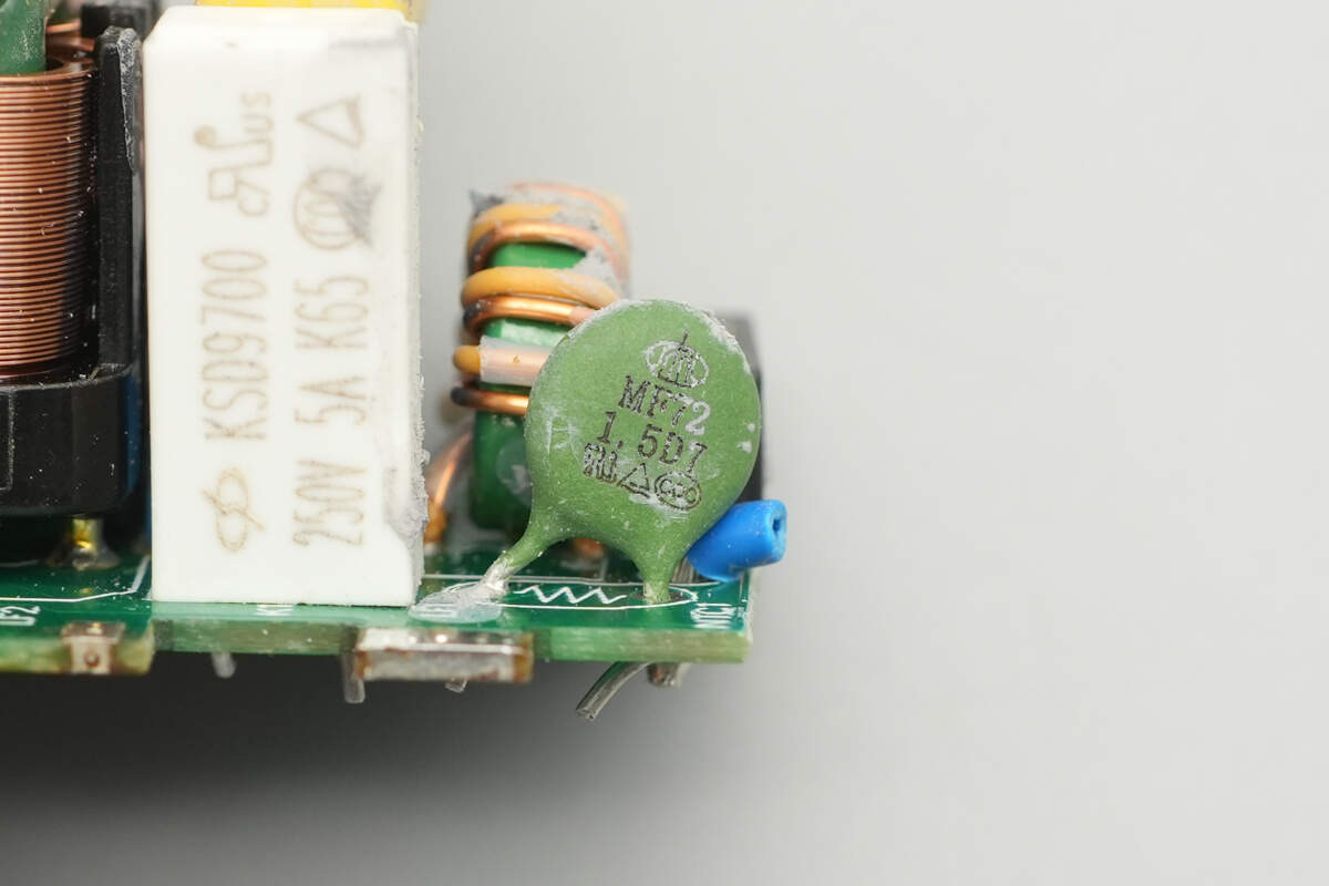
The NTC thermistor is from shiheng, part of the MF72 series, and is used to suppress inrush current during power-on.

The KSD9700 thermal protector has a triggering temperature of 85°C and is used for internal overheat protection.
The common mode choke is a dual-wire wound type, used to filter out EMI interference.

The safety X2 capacitor is from SHXCC, with a specification of 0.68μF.
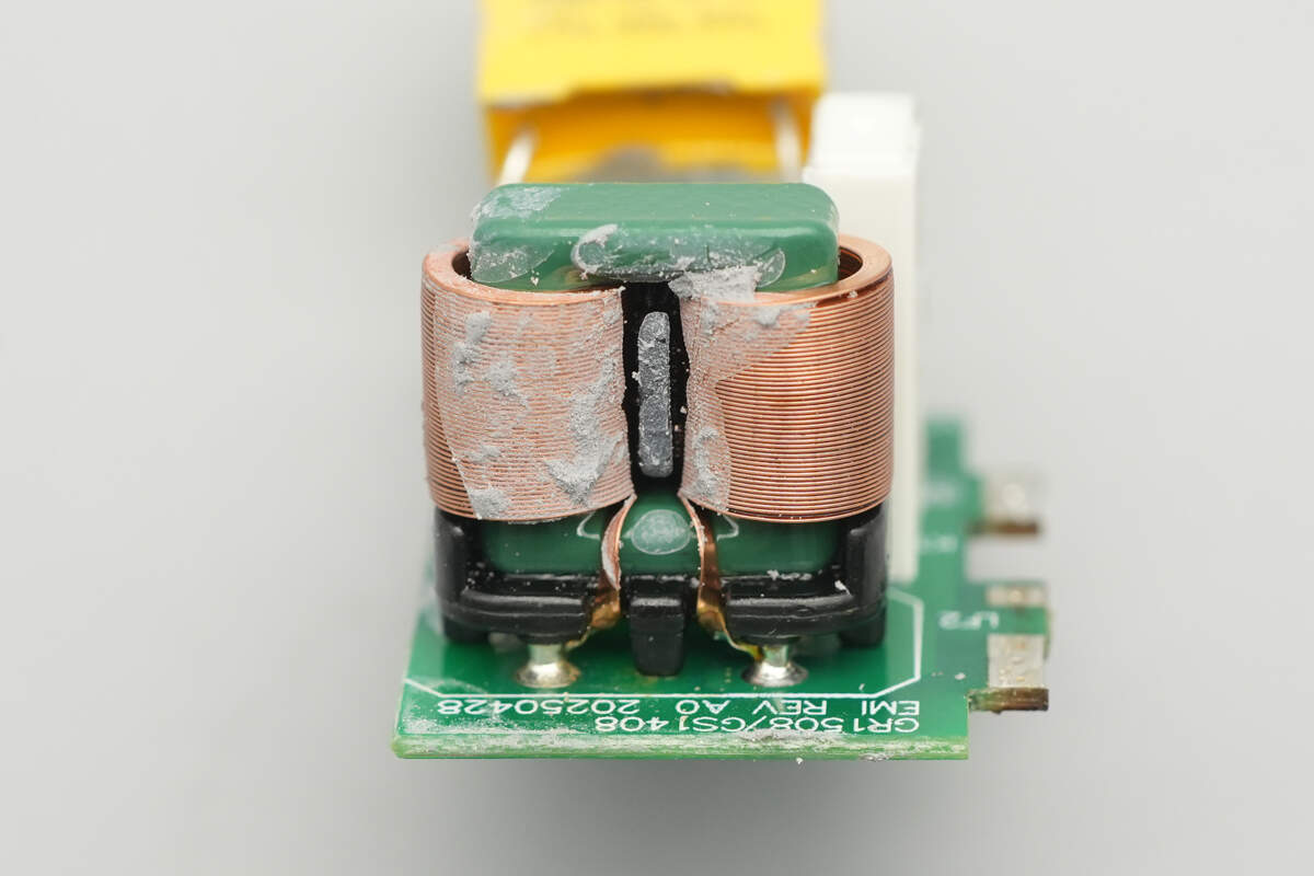
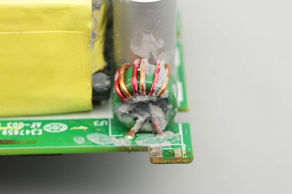
The secondary common mode choke is wound with flat copper tape.
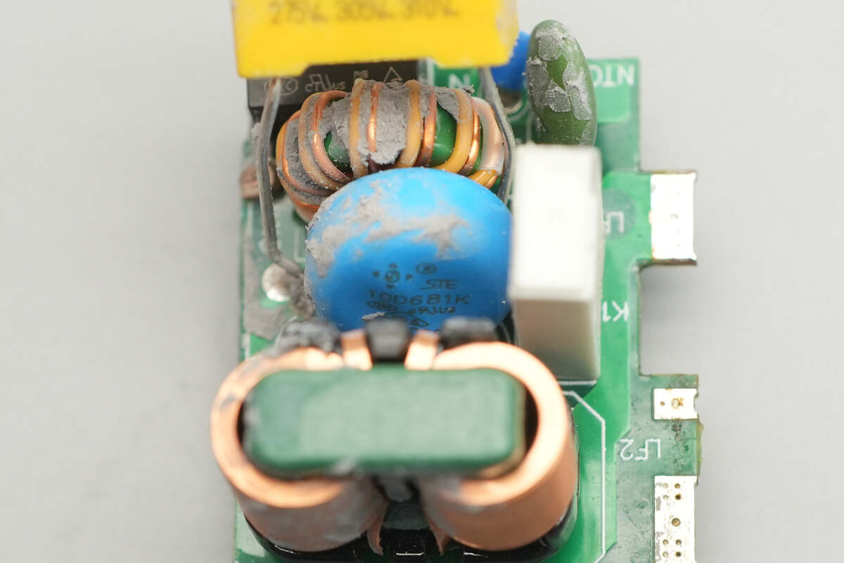
The 10D681K varistor is also from STE and is used for input over-voltage protection.
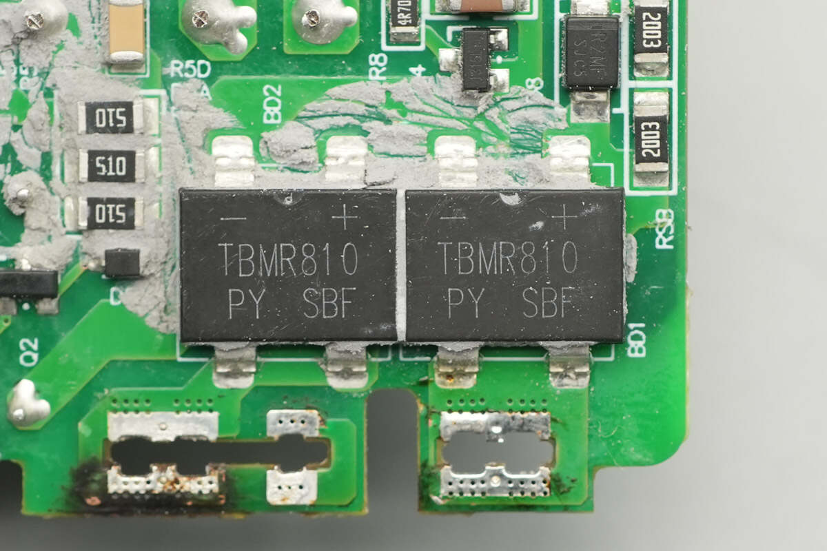
The two bridge rectifiers are from PY, model TBMR810, with a specification of 8A 1000V, and they feature a TBM package.
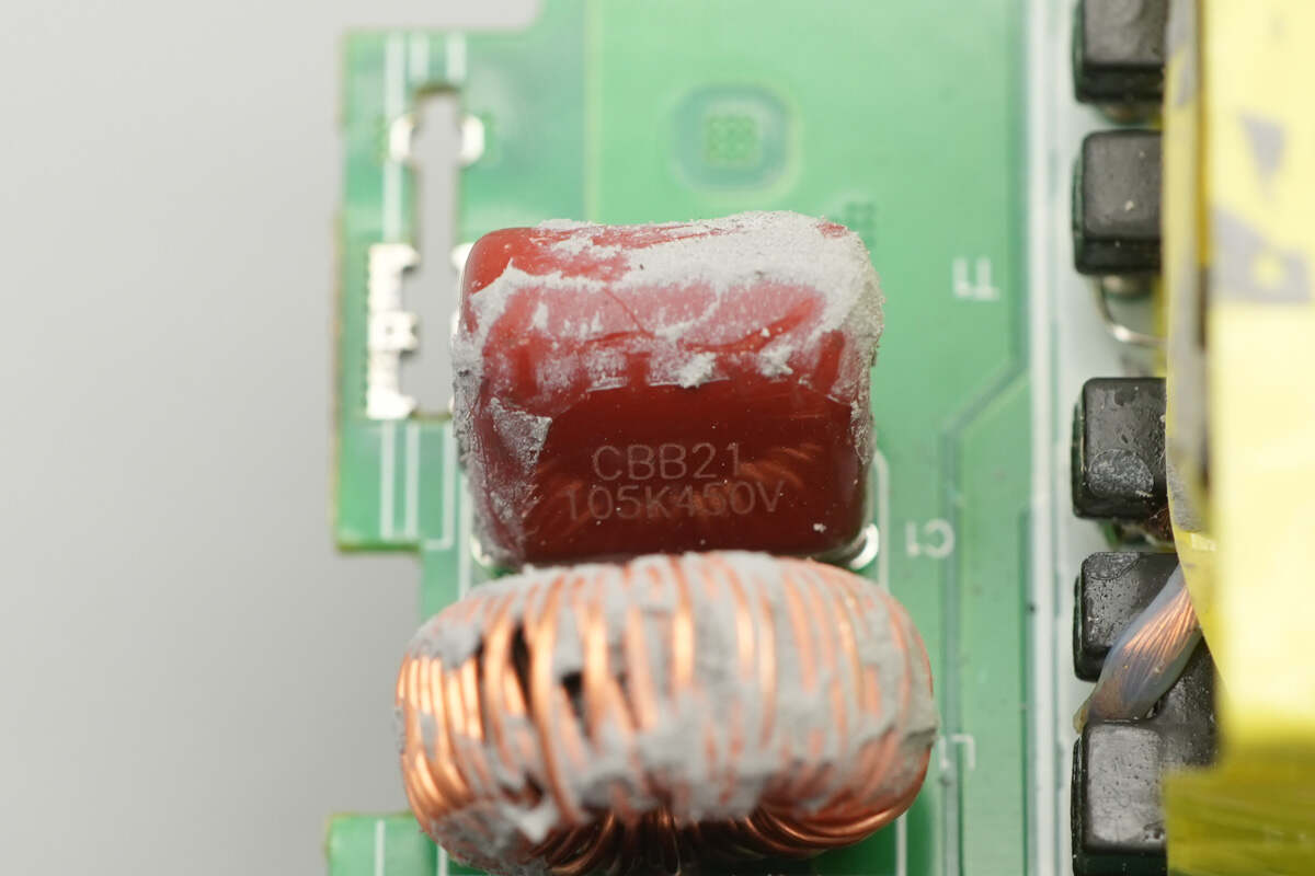
The CBB21 film capacitor has a specification of 1μF 450V.

Close-up of the filter inductor.

The other film capacitor has the same part number.
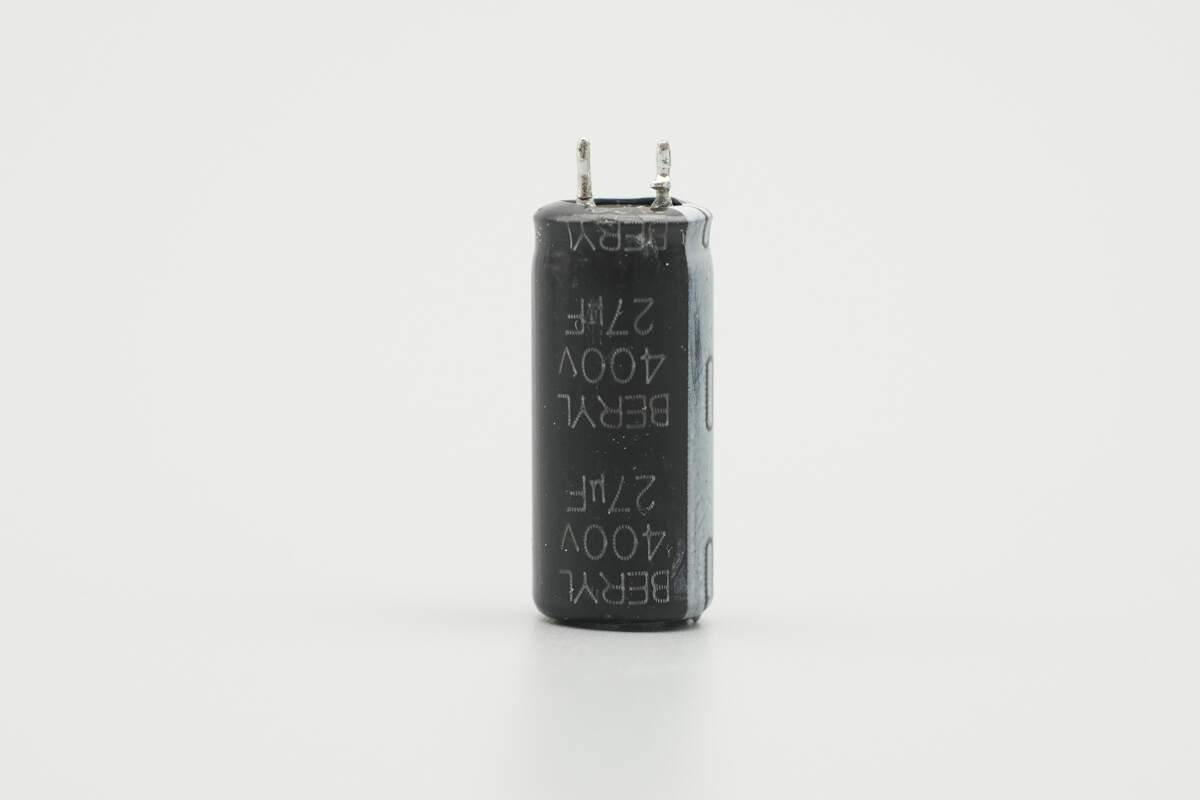
The high-voltage filtering electrolytic capacitor is from BERYL, with a specification of 400V 27μF.
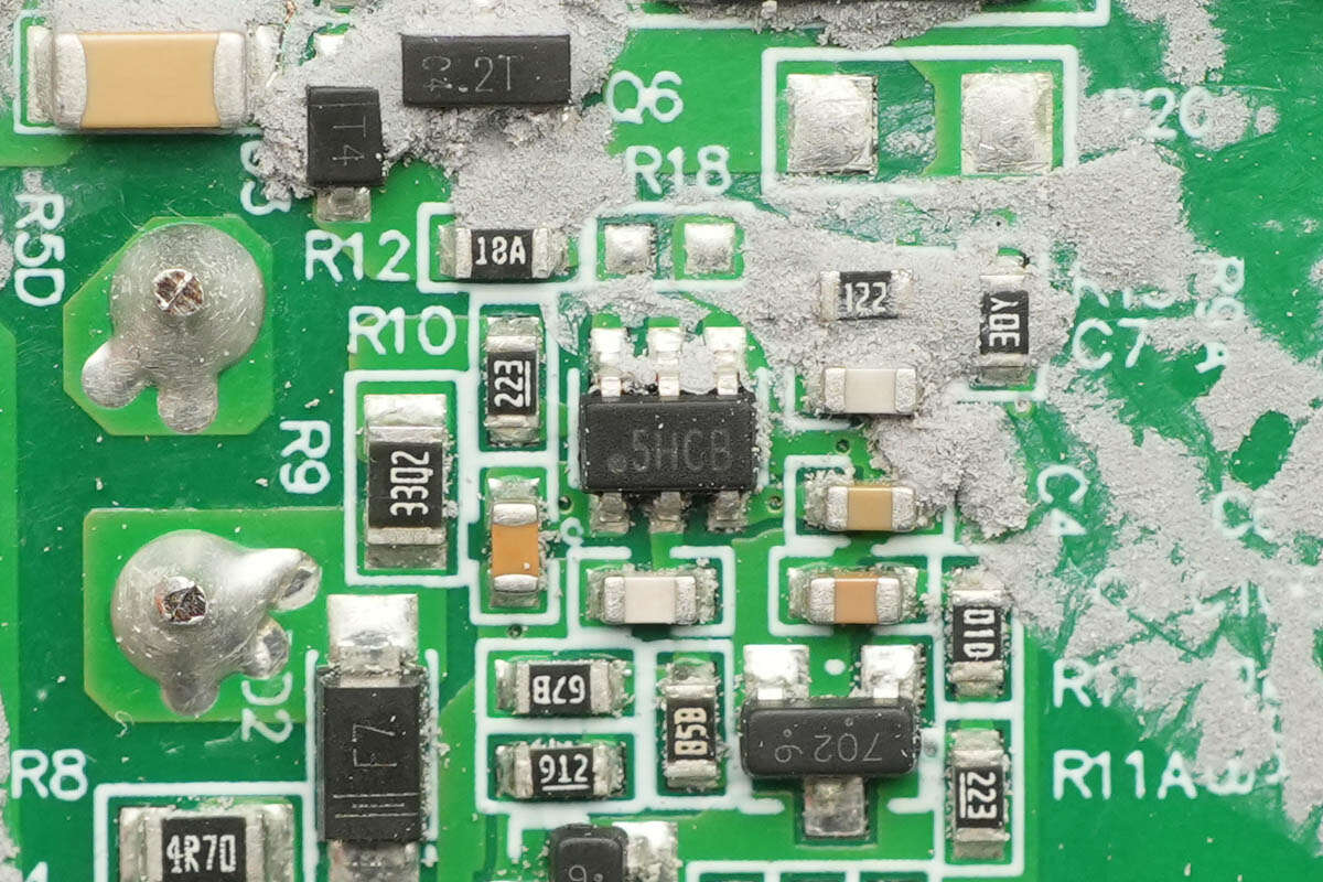
The primary control chip is from RENESAS, marked with "5H," and is the model iW3627-00. It is a single-stage AC/DC constant voltage controller with PFC functionality. The chip supports both isolated and non-isolated topologies, achieving extremely low load and line voltage regulation without the need for a secondary feedback circuit. It does not require external loop compensation components and comes in an SOT23 package.

The primary MOSFET is from SiCRED, marked with "180N080D88AS," and the model is SMC180N080D88AS. It is a SiC power device with a voltage rating of 800V, a conduction resistance of 165mΩ, and is packaged in a DFN 8x8 format.
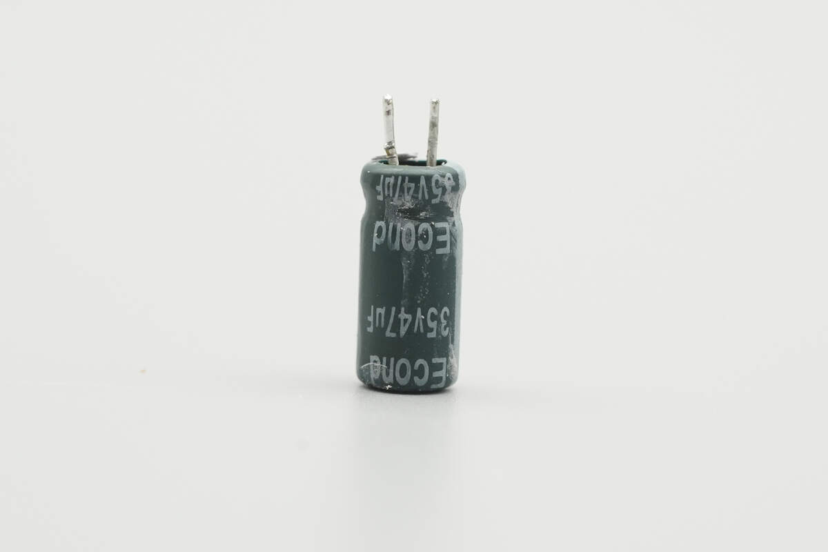
The capacitor that supplies power to the master control chip is from Econd, with a specification of 400V 10μF.
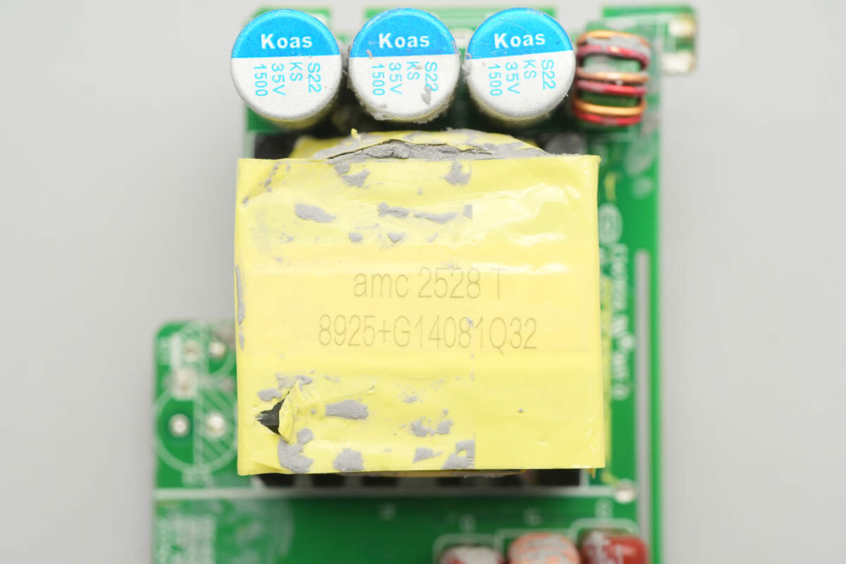
Close-up of the transformer.
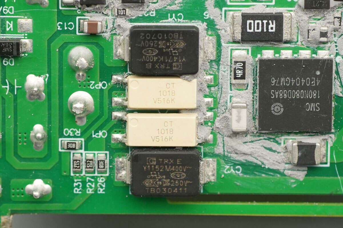
Close-up of two CT 1018 optocouplers.
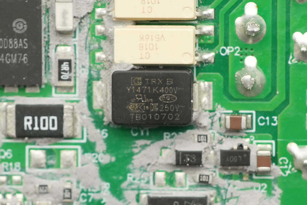
The SMD Y capacitor is from TRX, with the part number TMY1471K. Its compact size and lightweight design make it ideal for high-density power products, such as GaN fast chargers.
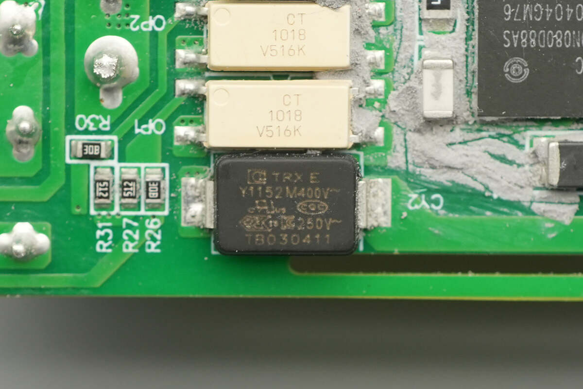
The other TRX SMD Y capacitor has the part number TMY1152M.

On this side, there are solid capacitors and a filter inductor.
The synchronous rectifier controller is from RENESAS, marked with "L9," and the model is iW610-01C. It supports QR, ZVS, ACF, and LLC switching power supply applications. The chip supports both DCM and CCM operation, as well as low-side and high-side applications. It has an output voltage range of 3-28V and comes in an SOT23 package.

The synchronous rectifiers are from CR MICRO, model CRSM100N15N3Z. They are NMOS transistors with a voltage rating of 150V, a conduction resistance of 9.5mΩ, and come in a DFN 5x6 Rib package.

The three solid capacitors for output filtering are from Koshin, with a specification of 35V 1500μF.
Close-up of the filter inductor.
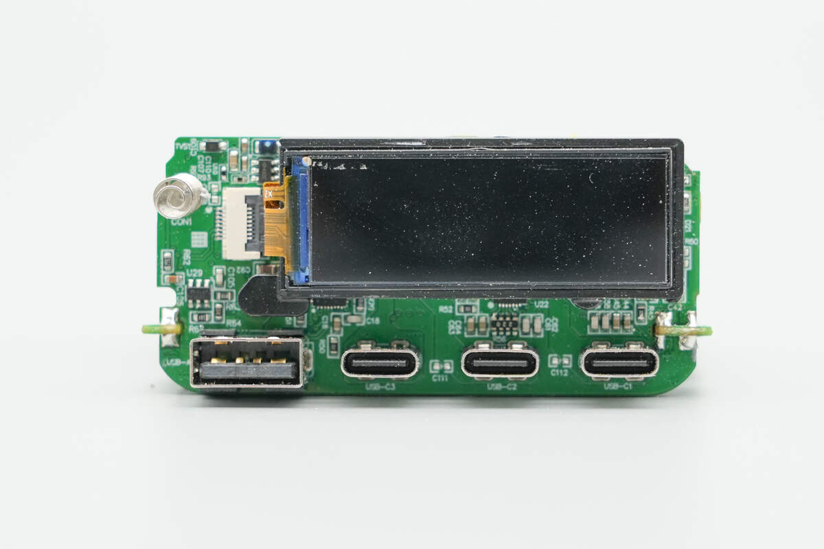
The small PCB at the output end is soldered onto a substrate. The screen is placed in a groove on the plastic plate for secure mounting and connected via a flex cable.
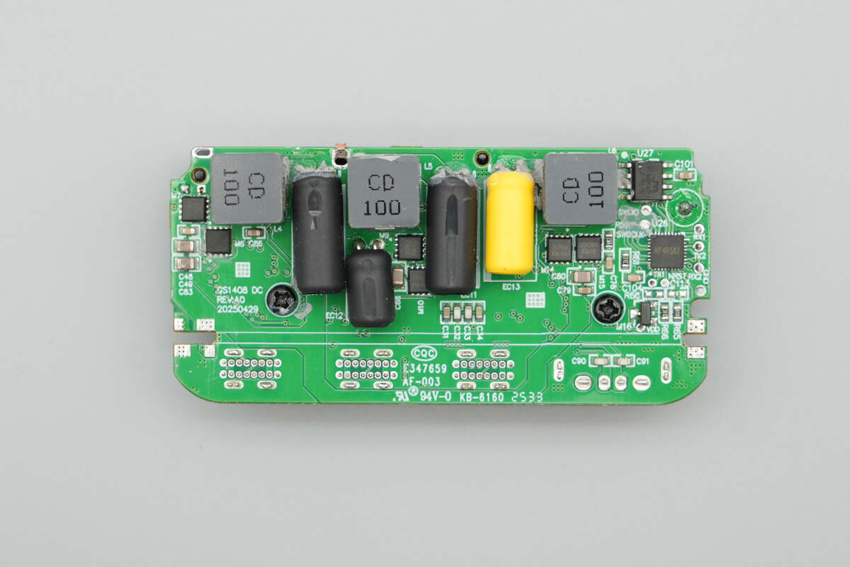
The back side features synchronous buck MOSFETs, buck inductors, and solid capacitors for three buck conversion circuits. It also includes the MCU and memory.
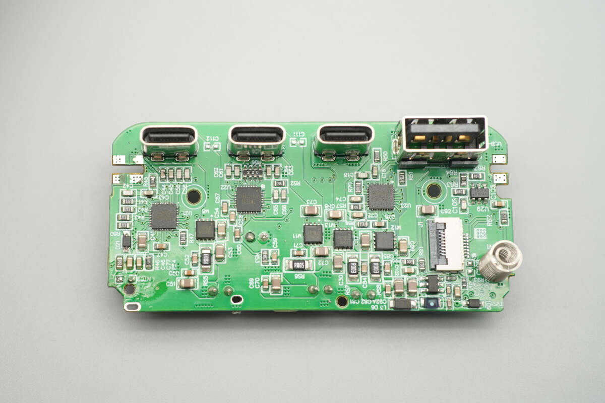
Remove the screen. The front of the small PCB features the buck protocol chips, output VBUS MOSFETs, switch-mode buck converters, touch controller chip, and other components.

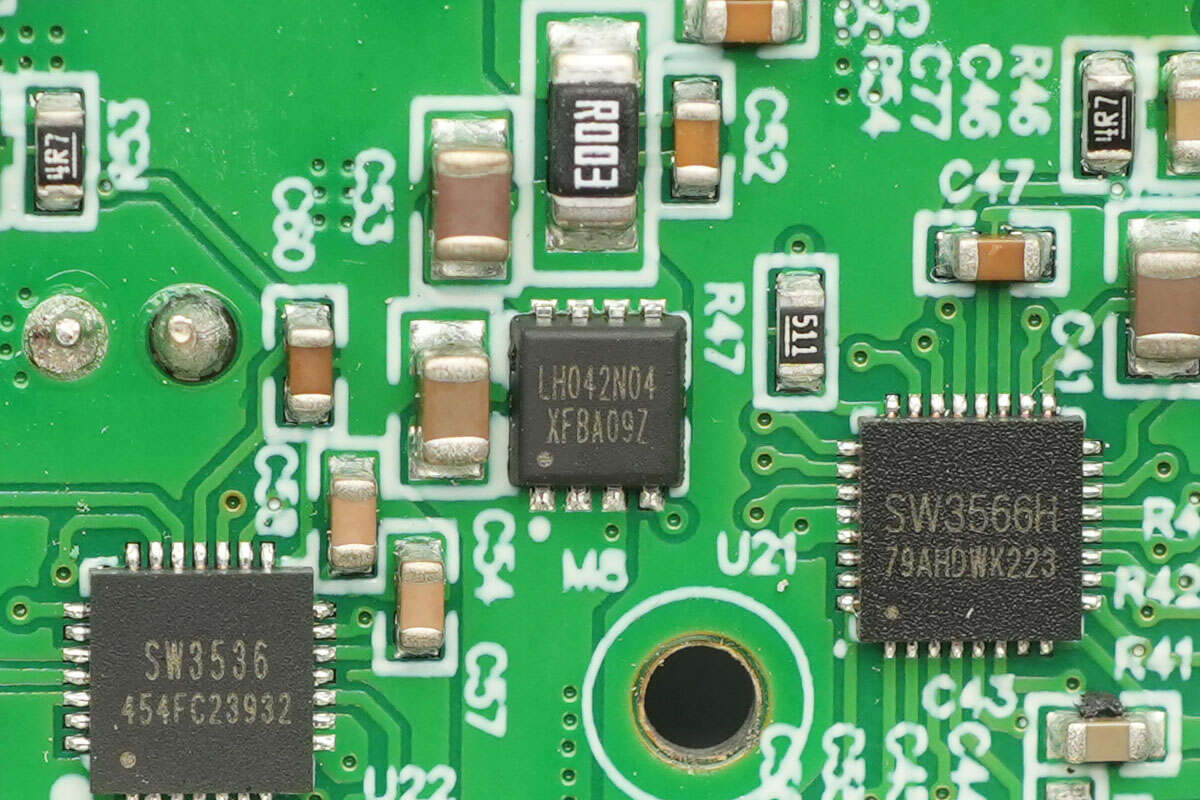
The buck protocol chip for USB-C1 is from iSmartWare, model SW3566H. This chip is a highly integrated dual-port charging SOC that supports multiple fast charging protocols for both USB-C and USB-A interfaces, with independent current limiting for each port. It integrates a highly efficient synchronous buck converter, supporting 20V7A and 28V5A output, and supports fast charging protocols such as PD3.1, QC, SCP, UFCS, and custom protocols, with a maximum output power of 140W.
The SW3566H includes CC/CV modes, dual-port management logic, and bus voltage detection. Paired with the corresponding buck MOSFETs and VBUS MOSFETs, it can achieve dual-port buck output. The built-in buck converter operates at a frequency of 180kHz and supports both PWM and PFM operating modes. Protection thresholds such as output current and line loss compensation can be set through the I2C interface, and the internal ADC enables data sampling for 9 channels, including input/output voltage, output current, and chip temperature. It also supports external MCU integration for parameter display.
The SW3566H supports an input voltage of up to 36V and a maximum output current of 7A. It features soft-start, input over-voltage/under-voltage protection, output over-voltage/under-voltage protection, output over-current/short-circuit protection, DP/DM/CC over-voltage protection, over-temperature protection, external NTC thermistor protection, and power-limiting protection. The chip is packaged in a QFN 4x4-32 format.

Here is the information about iSmartWare SW3566.

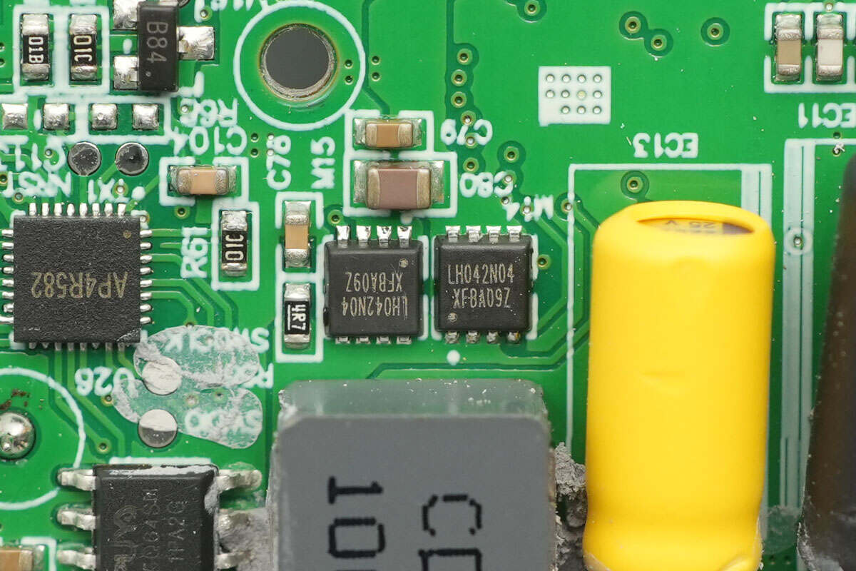
The synchronous buck-boost MOSFETs are from LIHOMICRO, model LH042N04. These are NMOS transistors with a voltage rating of 40V, a conduction resistance of 4.2mΩ, and are packaged in a DFN 3x3 format.

Close-up of the 10μH inductor.

The buck solid capacitor for output filtering is from Koshin, with a specification of 35V 220μF.
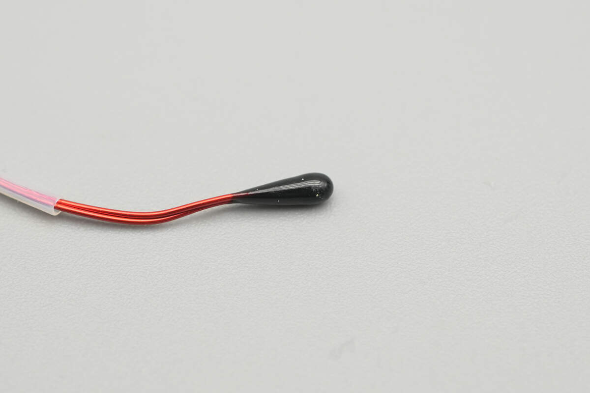
Close-up of the thermistor.
The output VBUS MOSFET for USB-C1 also uses the LIHOMICRO LH042N04.
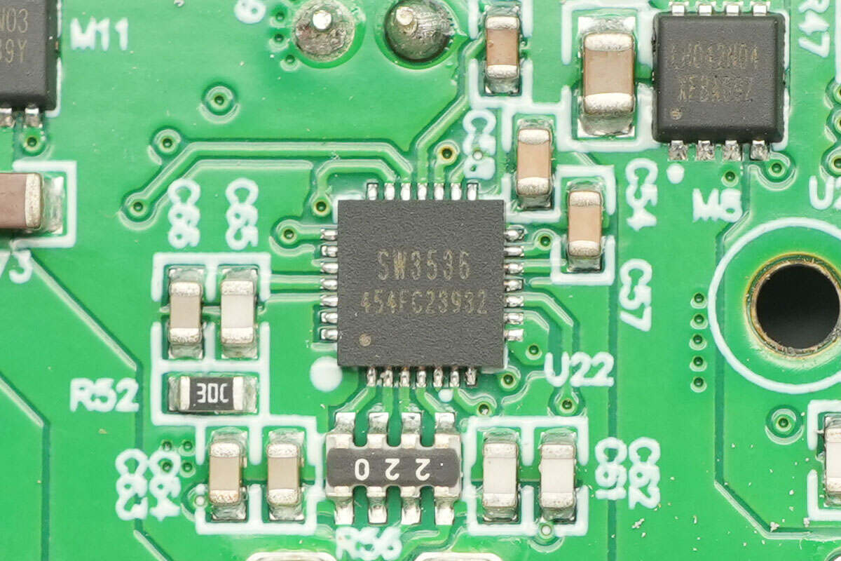
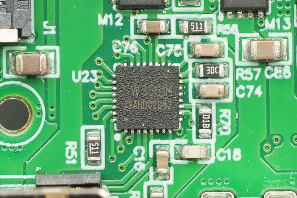
The buck protocol chip for USB-C2 is from iSmartWare, model SW3536. This is a highly integrated dual-port fast charging chip that supports USB-A + USB-C dual-port fast charging output, with independent current limiting for each port. It integrates a 7A high-efficiency synchronous buck converter and supports multiple fast charging protocols, including PPS, PD, QC, AFC, FCP, SCP, PE, SFCP, and TFCP, with a maximum output power of 140W.
The SW3536 integrates CC/CV modes, dual-port management logic, and dynamic power distribution between two chips, making it a complete and high-performance multi-fast-charging protocol dual-port charging solution. The SW3536 supports an input voltage of up to 36V, which makes it suitable for 12-24V input car charger applications. It is ideal for use in fast charging adapters, power strips, and car charging applications.

The two synchronous buck MOSFETs used in conjunction are also the LIHOMICRO LH042N04.
Close-up of the 10μH inductor used with it.

The buck solid capacitor for output filtering is from Koshin, with a specification of 35V 68μF.
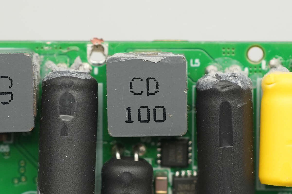
The buck protocol chip for USB-C3 and the USB-A port is from iSmartWare, model SW3561H. This is a buck SoC that supports dual USB-C port output. It integrates a high-efficiency synchronous buck controller, supporting 20V 5A power output, and is compatible with USB PD3.1 SPR. The chip integrates an ARM Cortex-M0 core and Type-C logic, supporting fast charging protocols such as PD3.1, QC, SCP, UFCS, and custom fast charge protocols.
The SW3561H supports dual USB-C port path control, line loss compensation, and, when paired with two synchronous buck MOSFETs and the corresponding VBUS MOSFETs for each port, can achieve dual-port buck output. The built-in buck converter operates at a default frequency of 180kHz, with support for customized operating frequencies and up to 100W power output, making it suitable for compact designs. The chip also integrates comprehensive protection features, including overheat protection, input/output over-voltage/under-voltage protection, output over-current protection, and data pin over-voltage protection. It is packaged in a QFN-32 format.
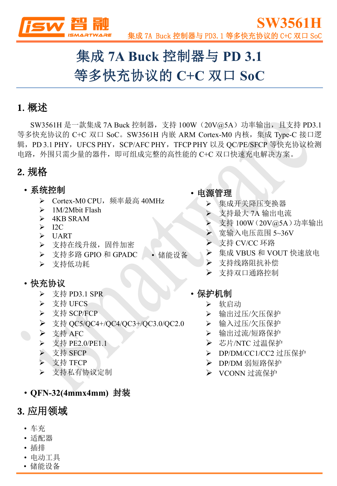
Here is the information about iSmartWare SW3561H.
The two synchronous buck MOSFETs are also the LIHOMICRO LH042N04.

Close-up of a 10μH inductor.
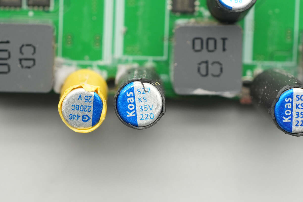
The buck solid capacitor for output filtering is from Koshin, with a specification of 35V 220μF.
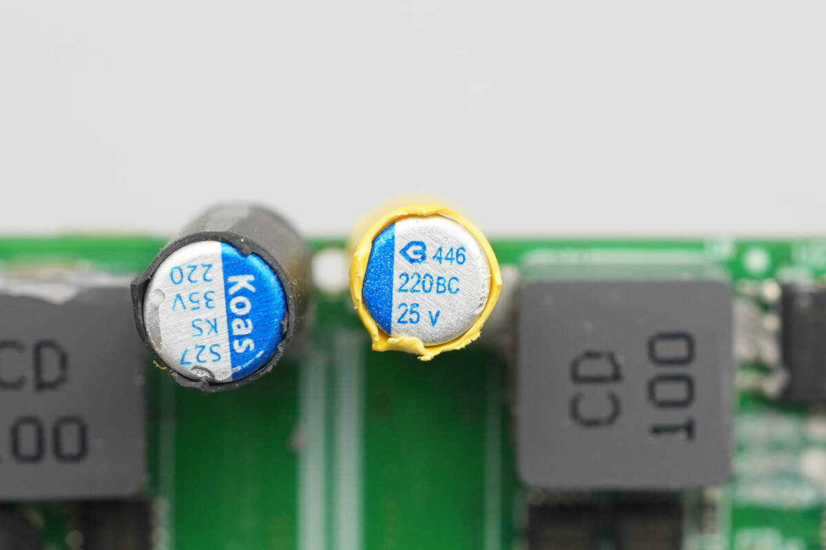
The other capacitor is from BERYL, with a specification of 25V 220μF.
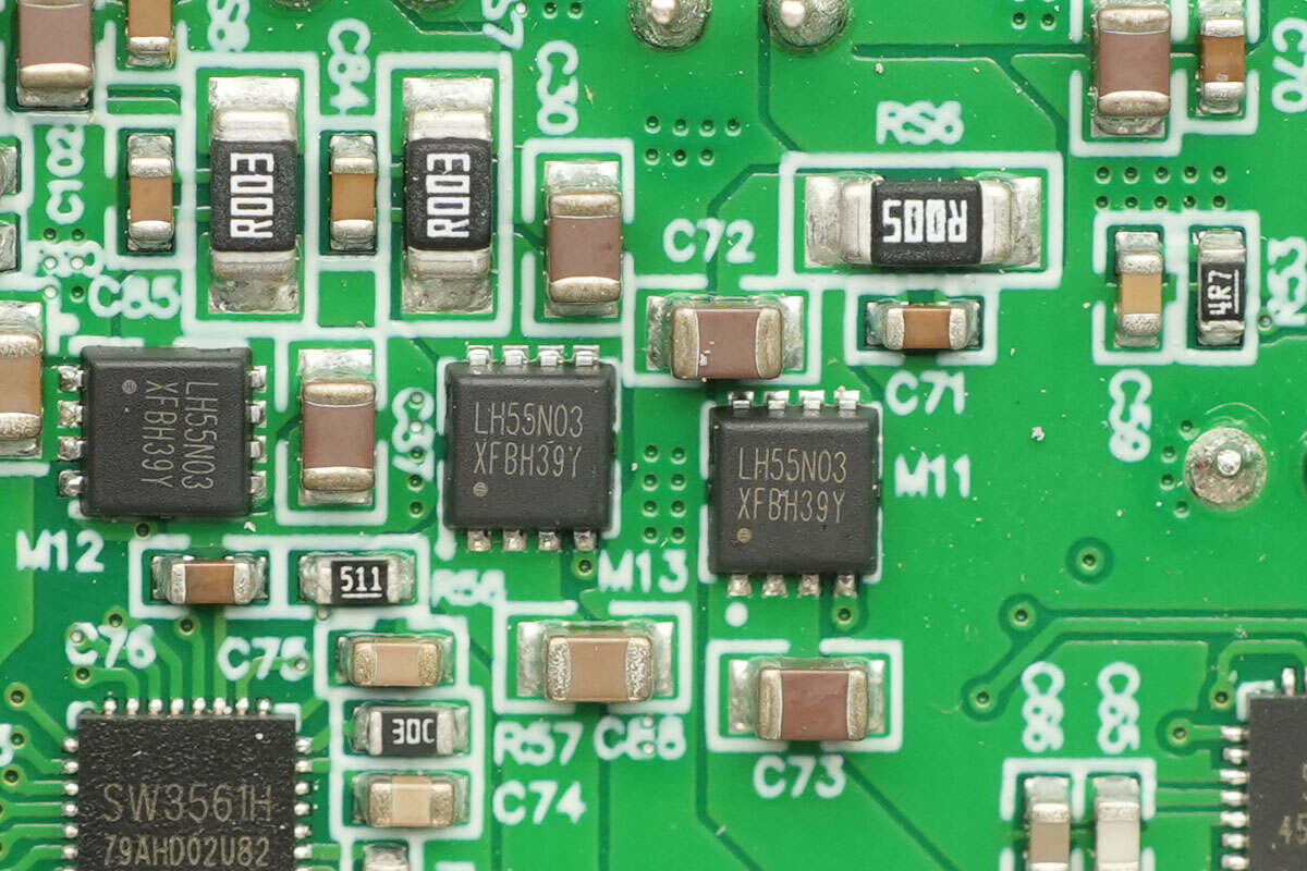
The VBUS MOSFETs for USB-C2 and USB-C3 are from LIHOMICRO, model LH55N03. These are NMOS transistors with a voltage rating of 30V, a conduction resistance of 5.5mΩ, and are packaged in a DFN 3x3 format.
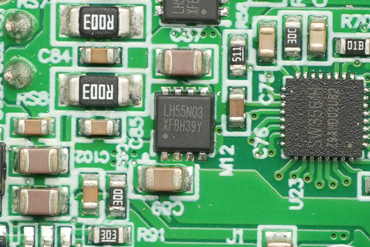
The output VBUS MOSFET for the USB-A port also uses the LIHOMICRO LH55N03.
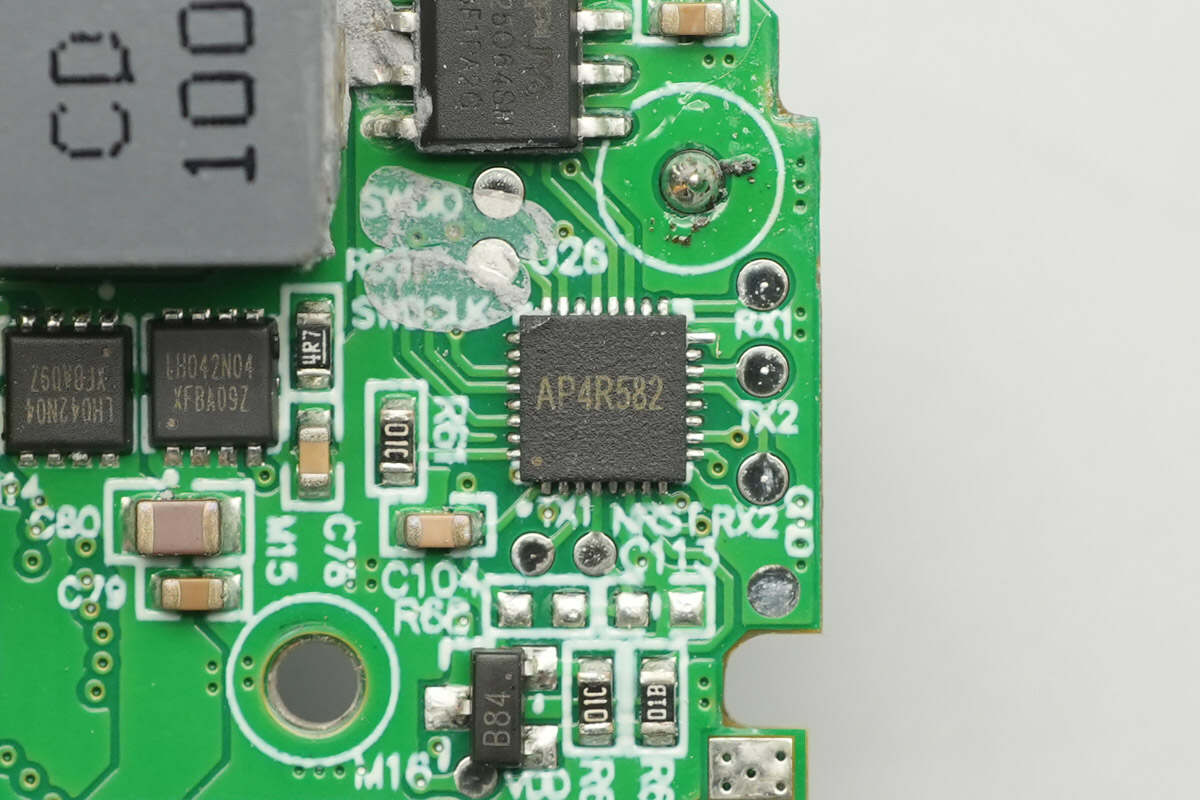
The MCU, marked with AP4R582, is packaged in a QFN32 format.

The memory is from Puya, model P25Q64SH, with a capacity of 8MB, and it is packaged in an SOP8 format.

The switch-mode buck converter chip is from Holtek, model HT7463C. This is a current-mode buck converter that supports an input voltage range of 4.5V to 60V. It operates at a frequency of 1250kHz, allowing the use of smaller external components while still maintaining low output voltage ripple. The chip comes in an SOT23-6 package.

The touch chip, marked with "1201A," is packaged in an SOT23-6 format.
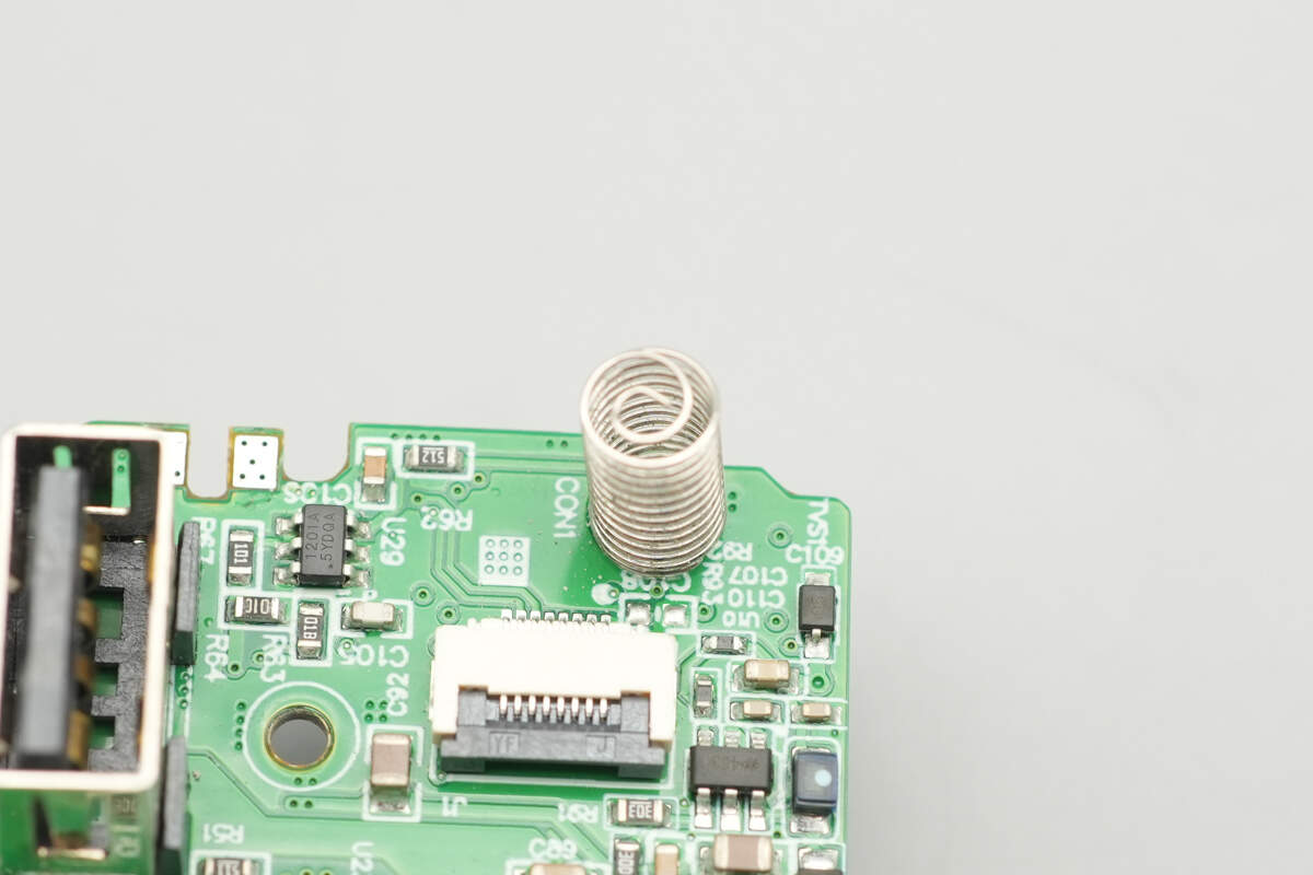
Close-up of the touch spring.
Well, those are all components of the Skyworth 140W SiC Charger with Smart Display.
Summary of ChargerLAB

Here is the component list of the Skyworth 140W SiC Charger with Smart Display for your convenience.
It is available in both white and black colors and comes with a 1.5-meter 240W fast charging cable. The TFT display supports interface usage status, power, total power, temperature, and time display. It is equipped with a touch button for easy operation. It is equipped with 3 USB-C ports and 1 USB-A port, supporting up to 140W output, and is compatible with fast charging protocols such as UFCS, PD, PPS, SCP, and others.
After taking it apart, we found that it uses the RENESAS iW3627-00 + iW610-01C solution. It features three independent DC-DC secondary buck circuits and utilizes iSmartWare's SW3566H, SW3536, and SW3561H highly integrated buck SOCs to control the four output ports.
The PCBA module is heavily filled with thermal adhesive and covered by a heatsink, with a thermistor included for temperature monitoring. The capacitors are wrapped in insulating tubing. The screen is supported and fixed in place by a frame. The workmanship is commendable.
Related Articles:
1. Teardown of CUKTECH 15 Charging Station (TA1406U)
2. Teardown of Xiaomi 45W GaN Pudding Charger (MDY-18-EZ)
3. Teardown of Anker Nano 45W GaN Charger with Display (A121D)