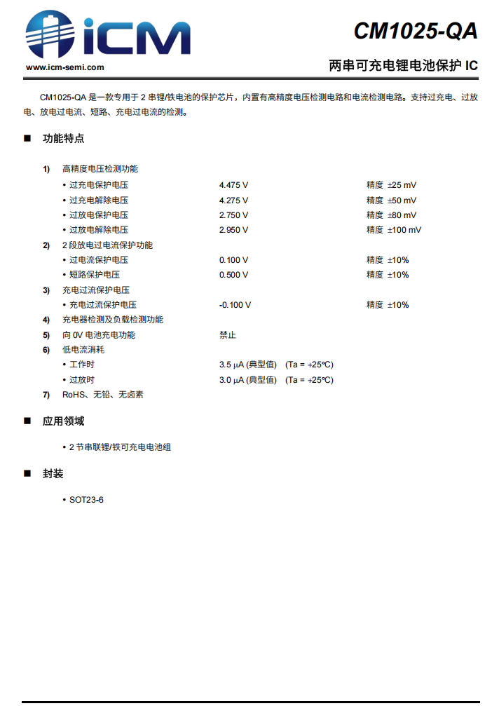
Introduction
Momax recently launched a magnetic power bank featuring a semi-solid battery with a 10,000mAh capacity, specifically designed to fit the iPhone 17 Pro Max. Once attached, the edges align perfectly without obstructing the rear camera module. The power bank has been Qi 2.2 certified and supports MPP 25W wireless fast charging. It also includes a USB-C port, supporting 30W input and output. Next, we will disassemble this power bank to examine its internal structure and material design.
Product Appearance
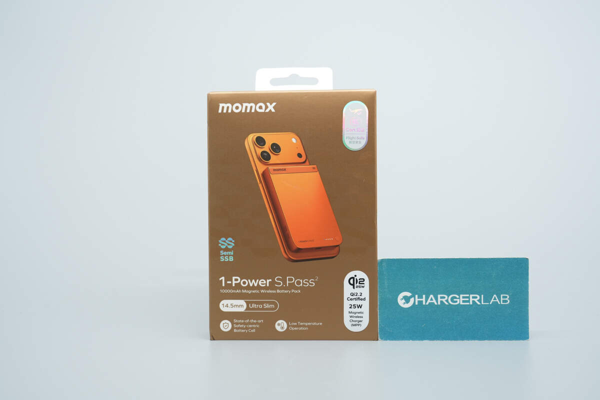
The front of the packaging features the brand logo, a rendering of the product magnetically attaching to the iPhone 17 Pro Max, the product name, some technical specifications, and the Qi2.2 certification mark.
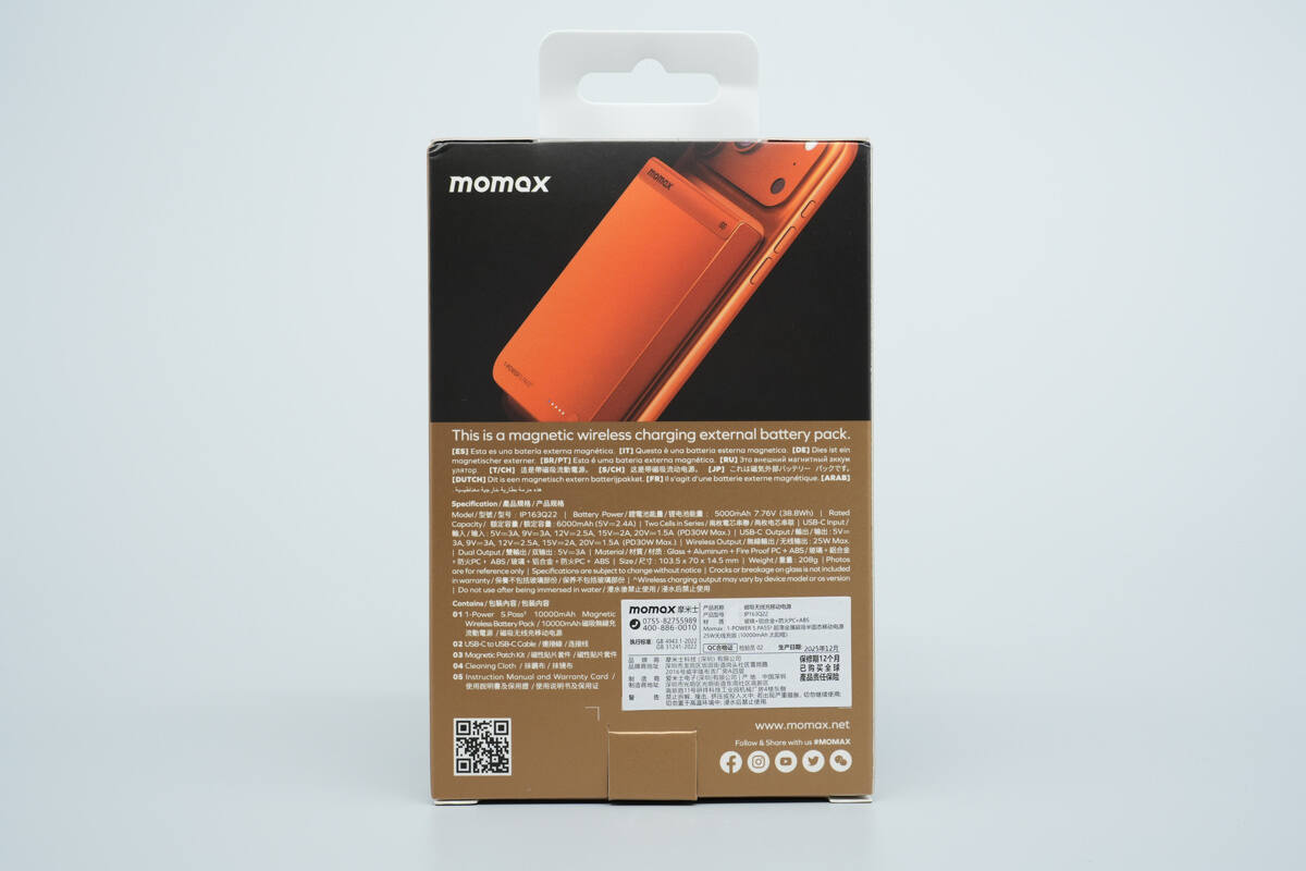
The back of the packaging includes key selling points, technical specifications, and important precautions.
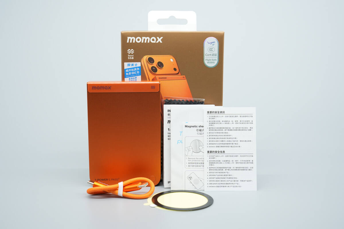
The packaging contains a power bank, a user manual, a dual USB-C cable, and a magnetic phone attachment plate.
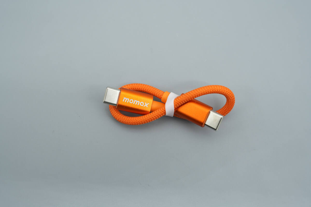
The included dual USB-C cable matches the power bank in orange color and features a braided outer sheath.
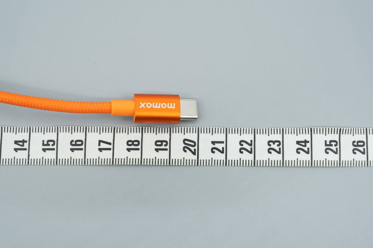
The length of the cable is about 20 cm (7.87 inches).
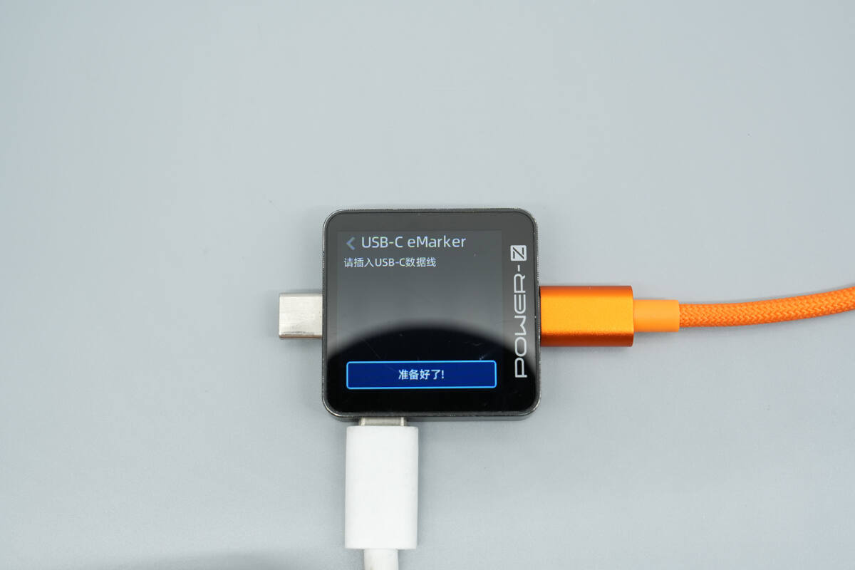
ChargerLAB POWER-Z KM003C shows it doesn't have an E-Marker chip.
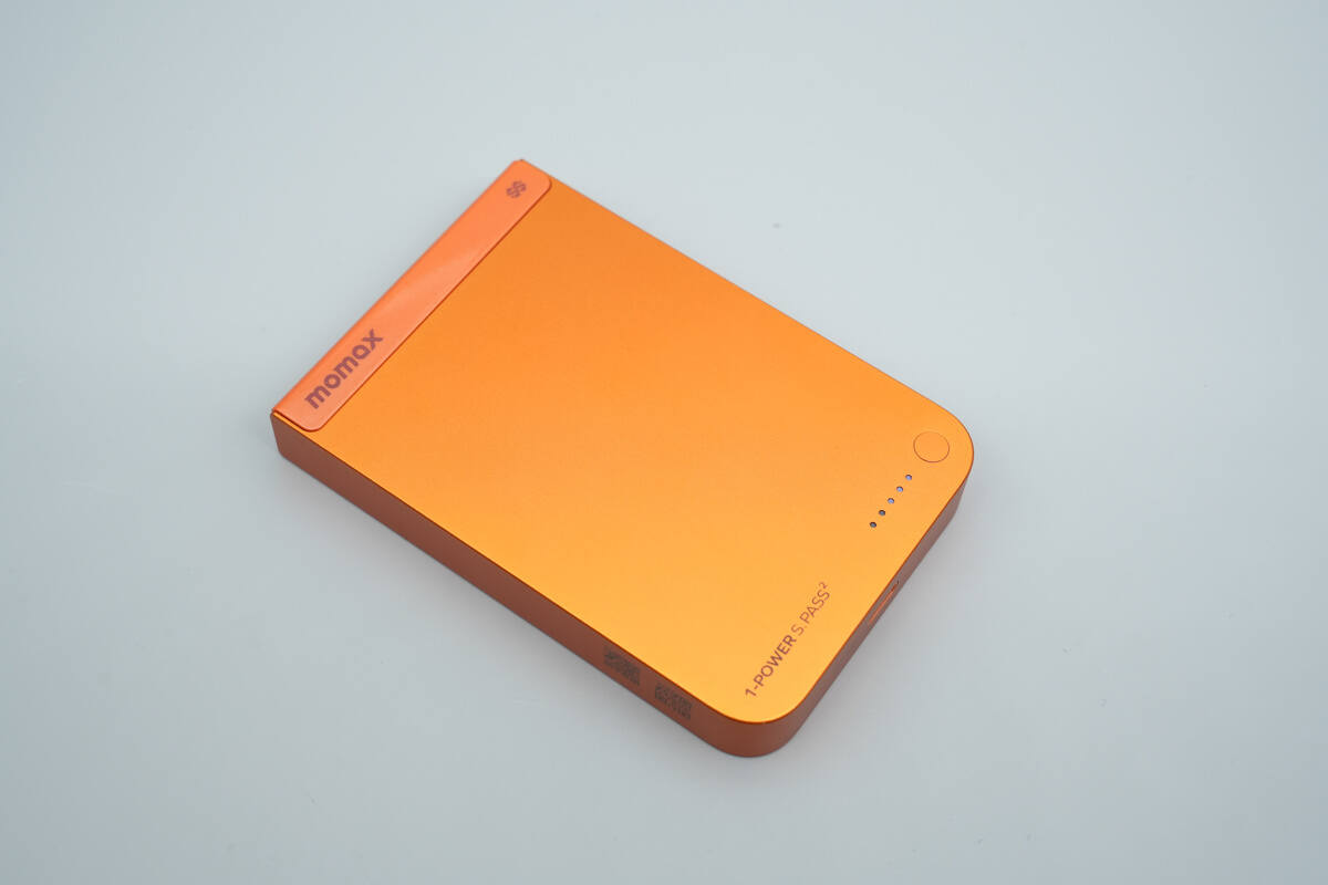
It features a flat rectangular body with power indicator lights and a button located in the bottom right corner.
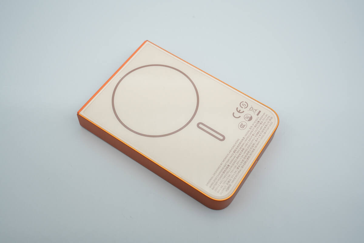
The other side displays the technical specifications and features a skin-like coating.
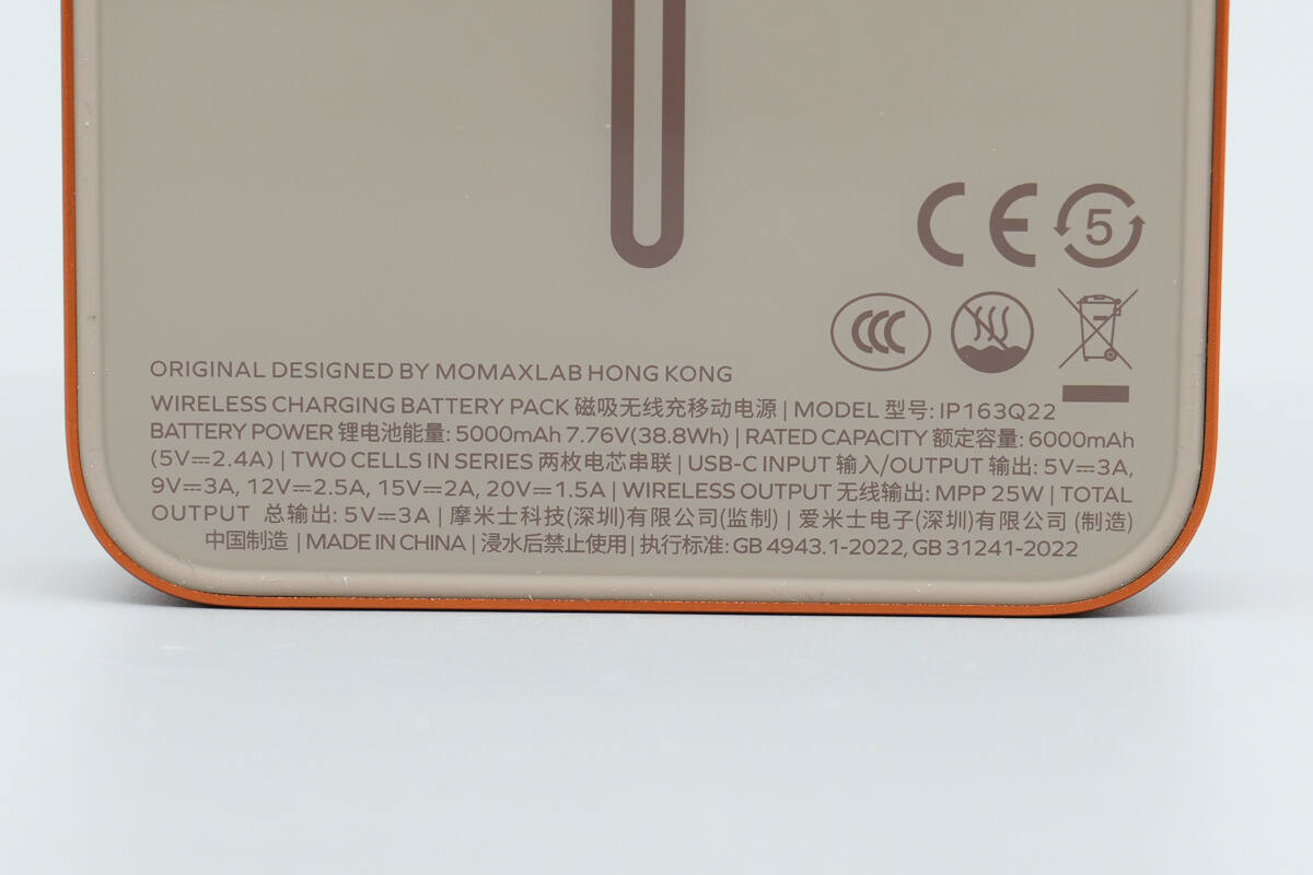
ORIGINAL DESIGNED BY MOMAXLAB HONG KONG
Model: IP163Q22
BATTERY POWER: 5000mAh 7.76V (38.8Wh) | RATED CAPACITY: 6000mAh (5V2.4A)
TWO CELLS IN SERIES
USB-C INPUT/OUTPUT: 5V3A, 9V3A, 12V2.5A, 15V2A, 20V1.5A
WIRELESS OUTPUT: MPP 25W
TOTAL OUTPUT: 5V3A
Made in China | DO NOT USE AFTER WATER IMMERSION
Standards: GB 4943.1-2022, GB 31241-2022
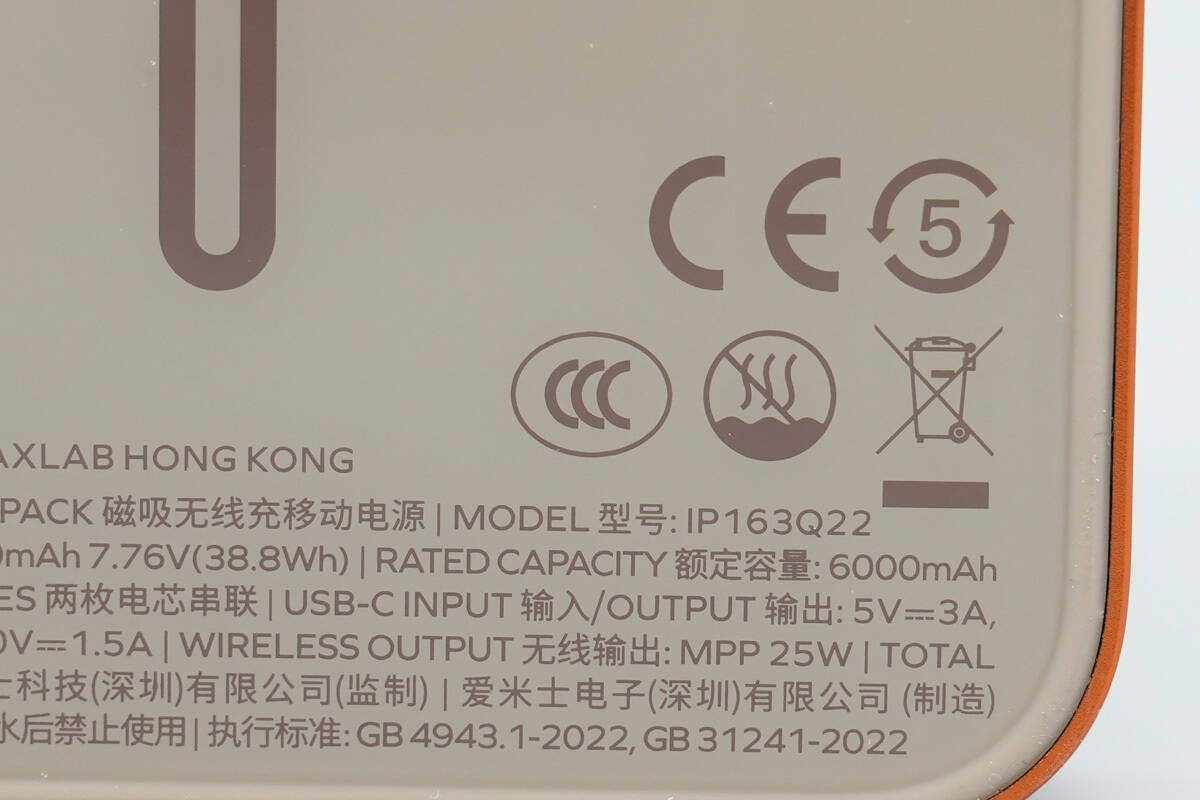
It has passed the CCC certification.
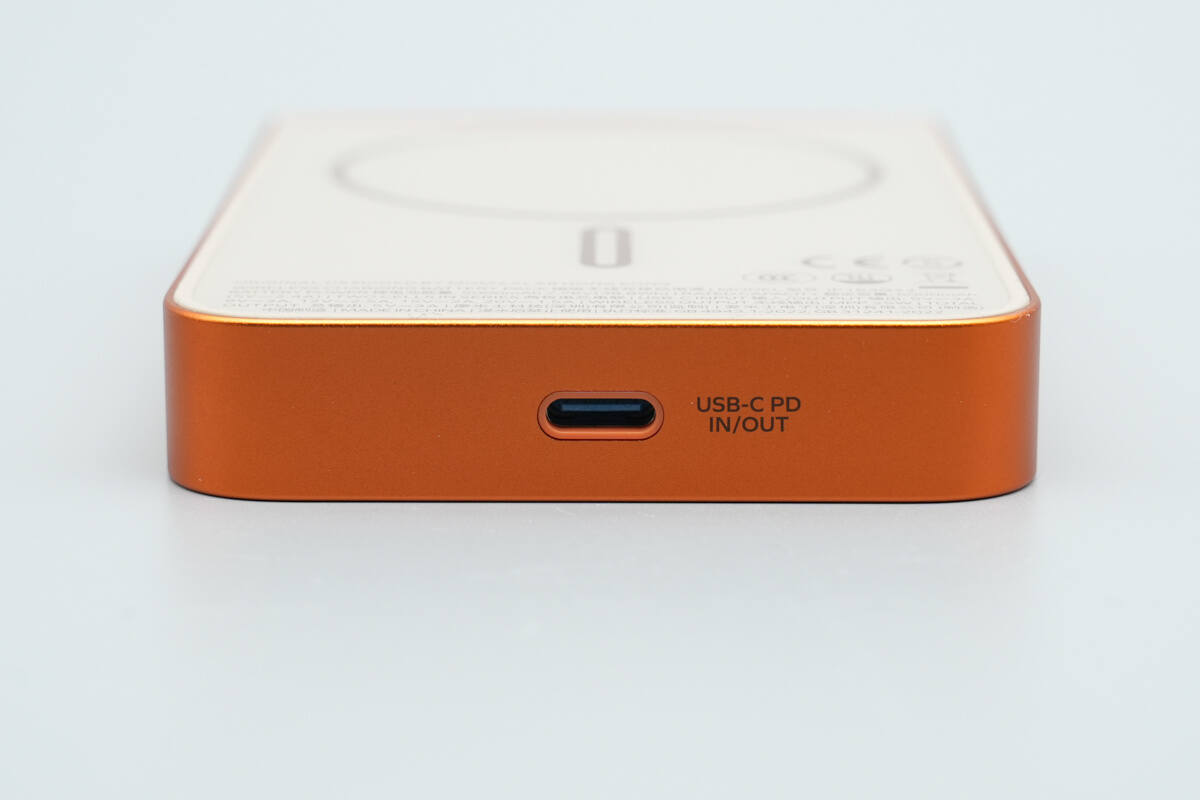
The bottom features a USB-C port that supports both input and output.
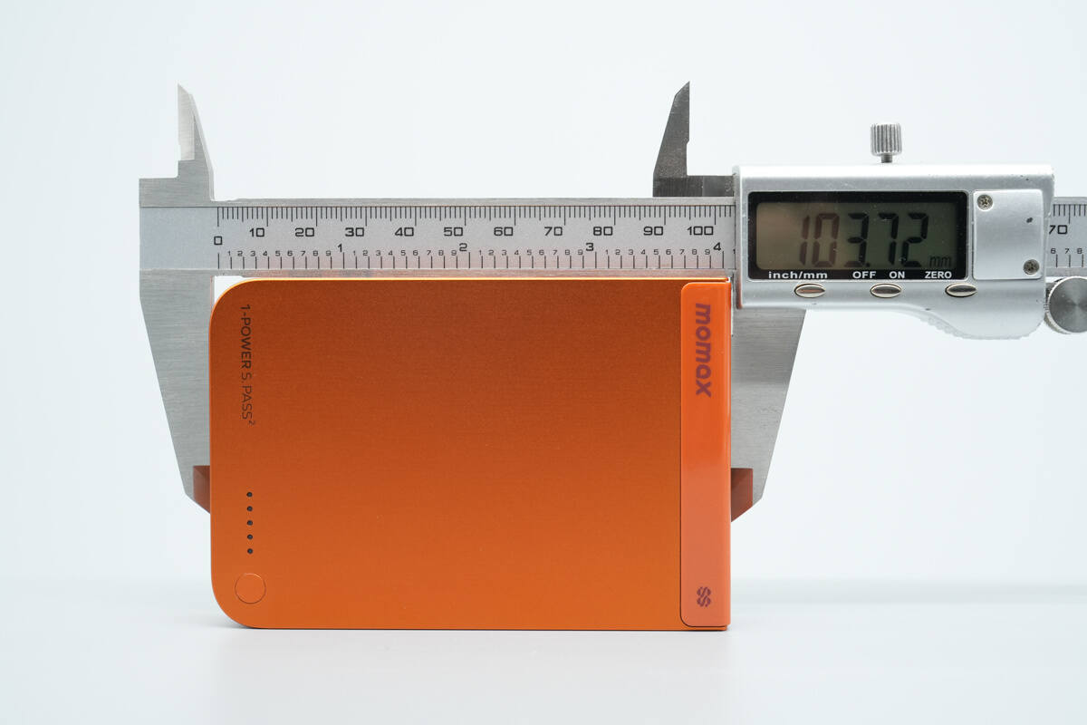
The length of the power bank is about 103.72 mm (4.083 inches).
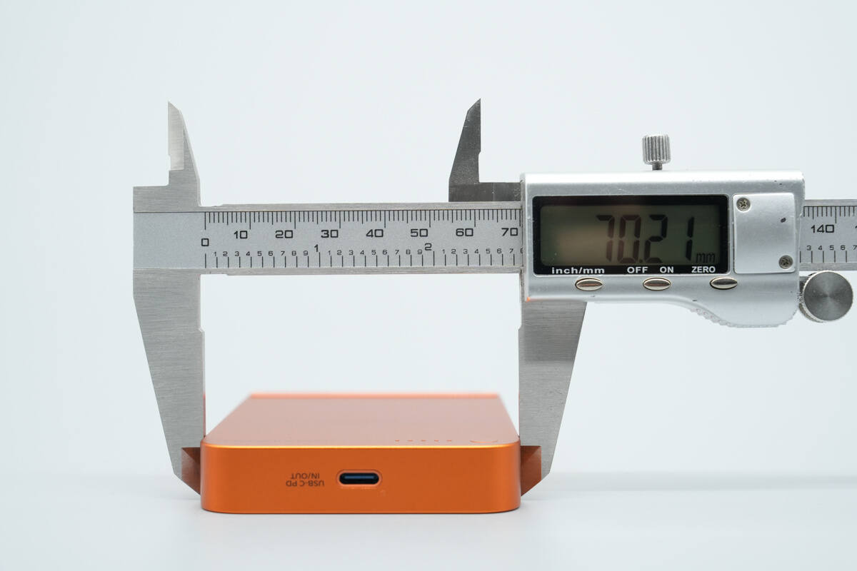
The width is about 70.21 mm (2.76 inches).
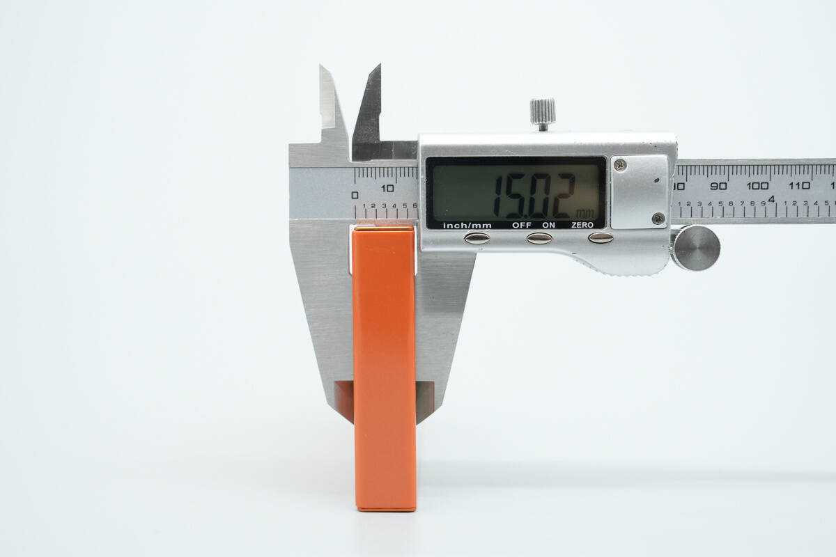
The thickness is about 15.02 mm (0.59 inches).
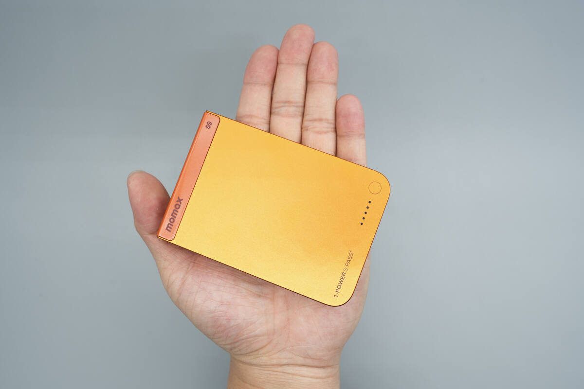
That's how big it is in the hand.

Usage scenarios overview: It is perfectly compatible with the iPhone 17 Pro Max.
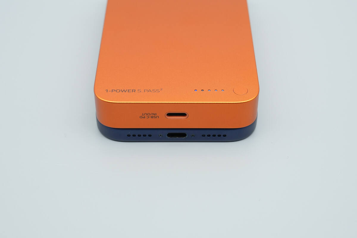
The bottom surface is aligned with the bottom surface of the iPhone 17 Pro Max, and the rounded corner design matches the curvature of the phone’s frame.
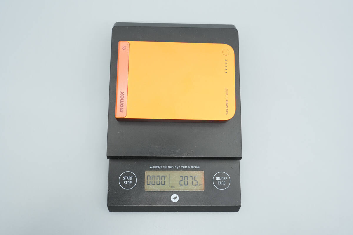
The weight is about 207.5 g (7.32 oz).
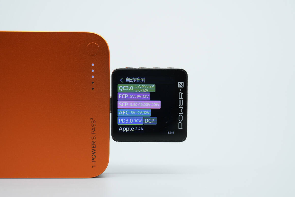
ChargerLAB POWER-Z KM003C shows that the USB-C port supports PD 3.0, QC 3.0, FCP, SCP, AFC, DCP, and Apple 2.4A charging protocols.
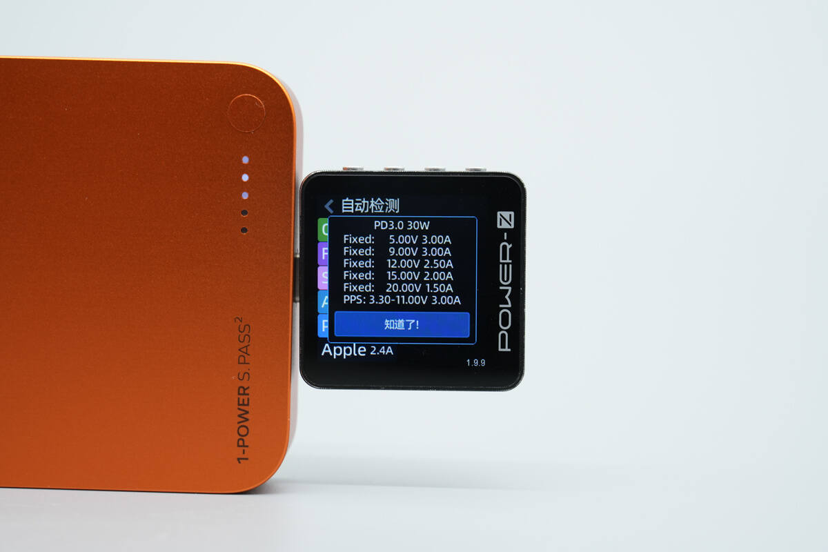
And it has five fixed PDOs of 5V3A, 9V3A, 12V2.5A, 15V2A, and 20V1.5A. It also has one set of PPS, which is 3.3-11V3A.
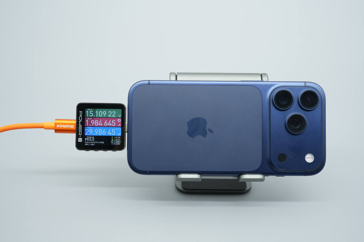
Using it to charge the iPhone 17 Pro Max, the USB-C port provides an output power of about 30W.
Teardown
Next, let's take it apart to see its internal components and structure.
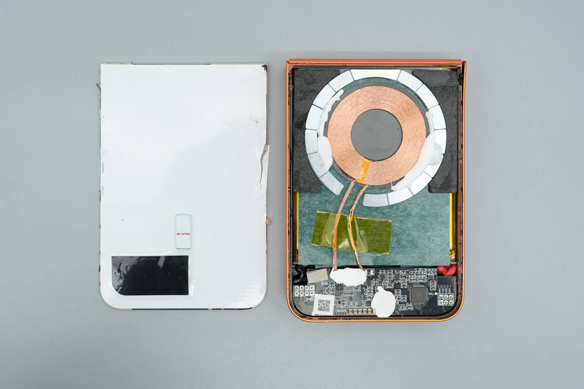
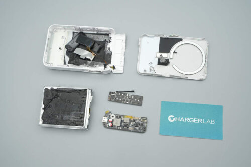
Prise open the casing along the seam. The upper section inside houses the wireless charging coil, with small magnets distributed around the outer ring of the coil, secured in place with foam and white adhesive. The coil's wiring consists of dual conductors, crossing over the battery cells and connecting to the PCB, which is secured with high-temperature insulating tape. The surface of the battery cells is covered with a large area of kraft paper for insulation.
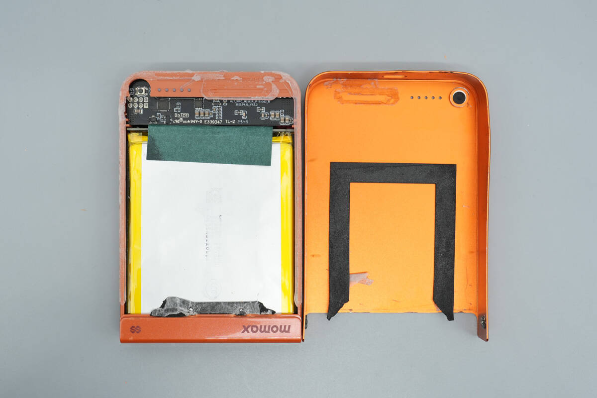
Open the other side of the casing, where the surface of the battery cells in contact with the casing is covered with black foam cushioning pads.
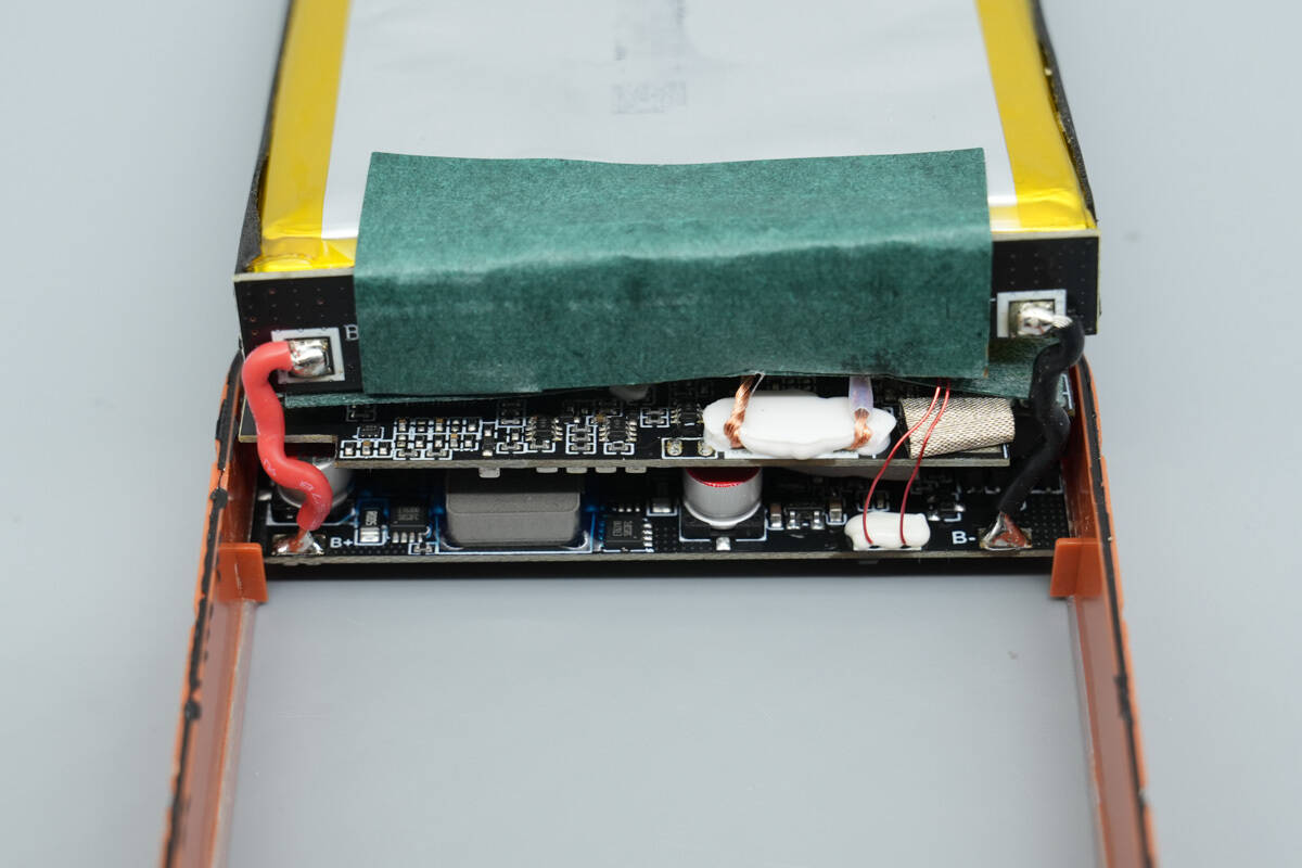
The motherboard features a stacked design, with the positive and negative terminals of the battery cells directly soldered onto the motherboard, and the solder points are secured with adhesive. The NTC thermistor is also fixed with white adhesive, with the probe extending directly to the battery side.
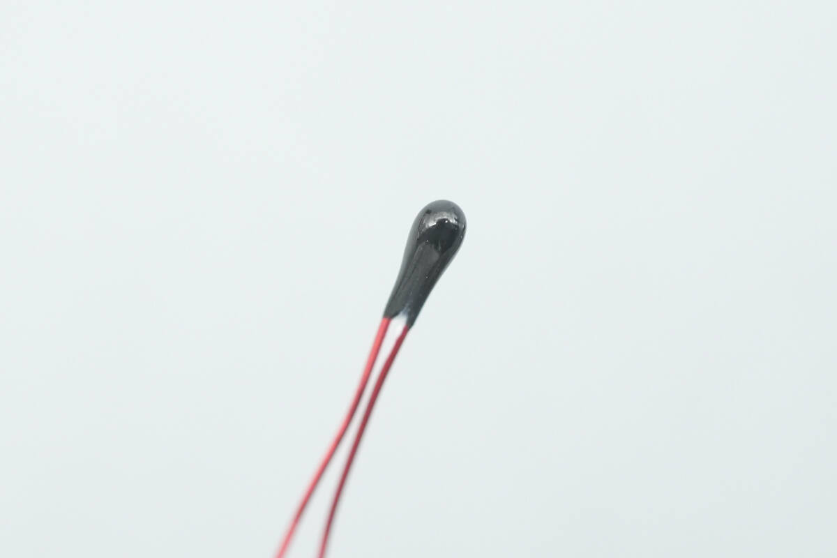
Close-up of the NTC thermistor.
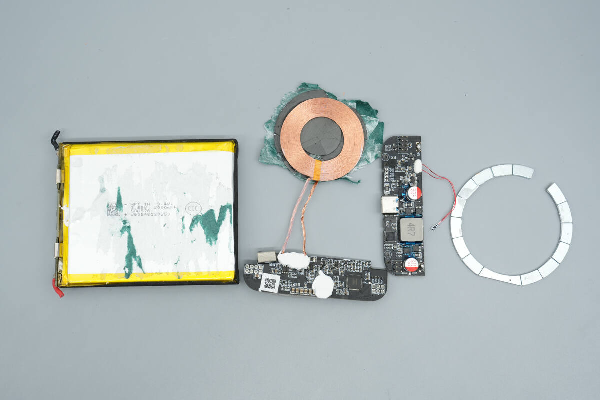
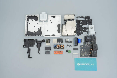
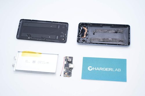
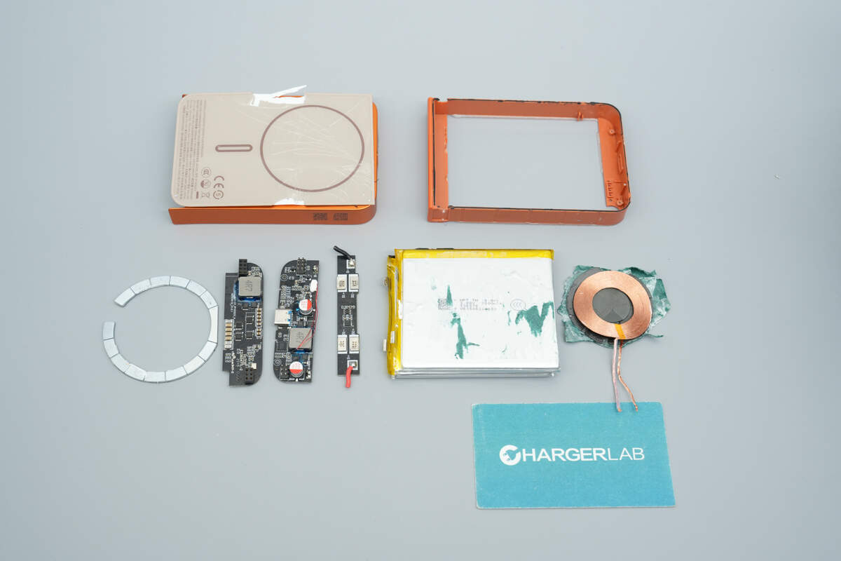
Separate the battery cell module, the coil, and the PCBA module.
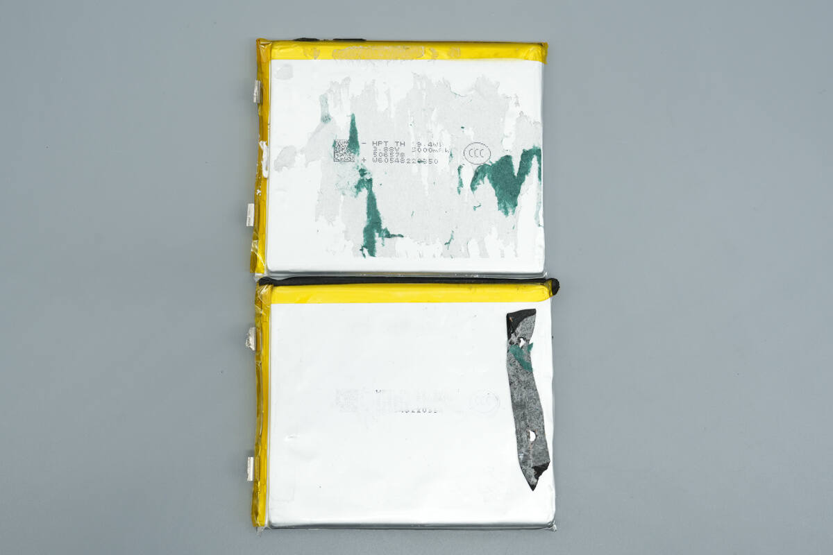
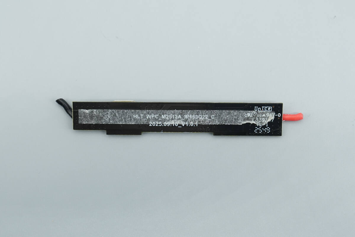
The side of the battery pack is equipped with a protection PCB, and the battery pack is composed of two half-solid-state battery cells.
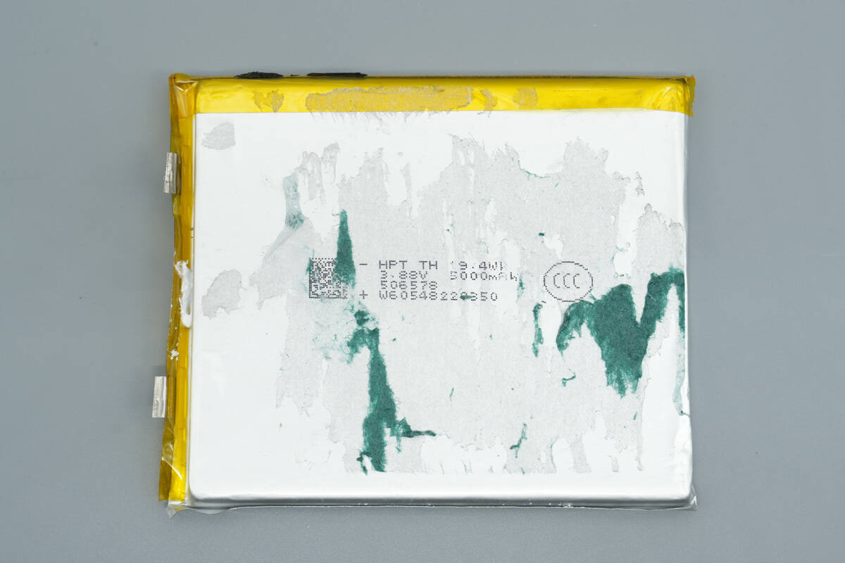
The battery cells are from HPT, with the model number 506578. The nominal voltage is 3.88V, the capacity is 5000mAh, and the energy is 37.0Wh. The cells have passed CCC certification.
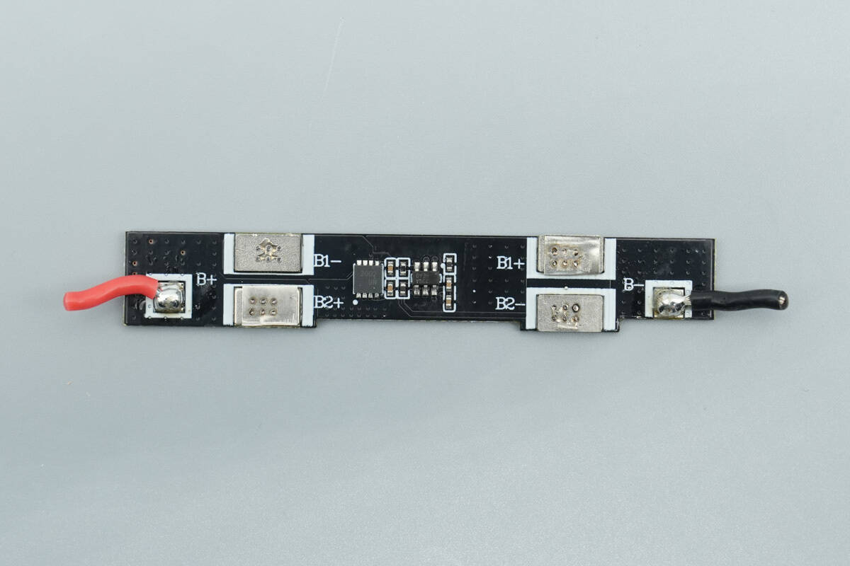
The front of the battery protection PCB features a battery protection chip and a battery protection MOSFET.
The front of the battery protection PCB features a battery protection chip and a battery protection MOSFET.
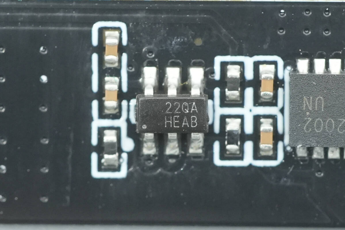
The battery protection chip is from iCM, marked with 22QA, and the model is CM1025-QA. This chip is specifically designed for 2-series lithium/iron phosphate batteries and features built-in high-precision voltage and current detection circuits. It supports overcharge, over-discharge, overcurrent discharge, short-circuit, and overcurrent charging protection.
Here is the information about iCM CM1025-QA.
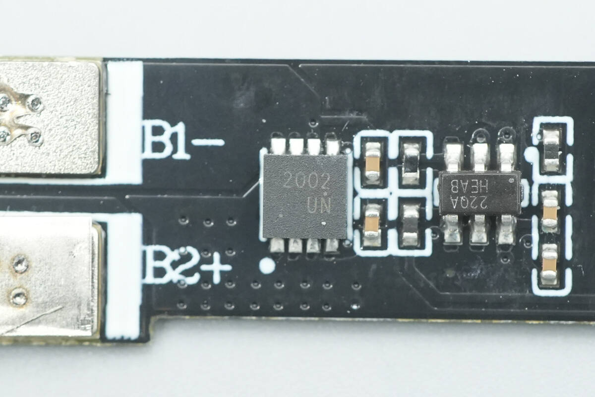
The battery protection MOSFET is marked with 2002 and is used for overcharge, over-discharge, and overcurrent protection in the built-in lithium battery.
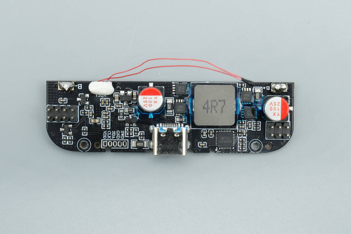
The front of the PCBA module features a buck-boost controller, an inductor, synchronous buck-boost MOSFETs, and filtering solid-state capacitors.
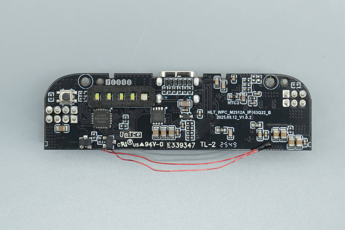
The back of the PCBA module features a protocol chip, VBUS MOSFET, and LED indicators. The area around the LEDs is covered with black light-blocking foam to prevent light leakage.
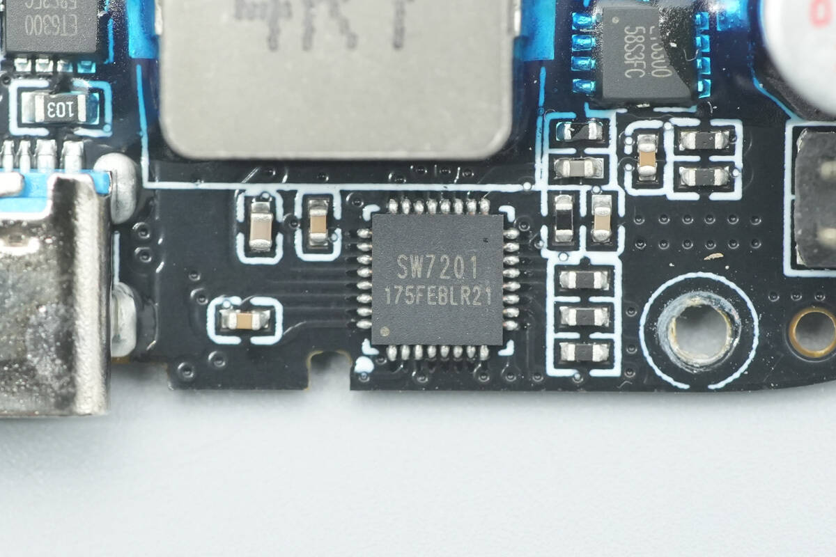
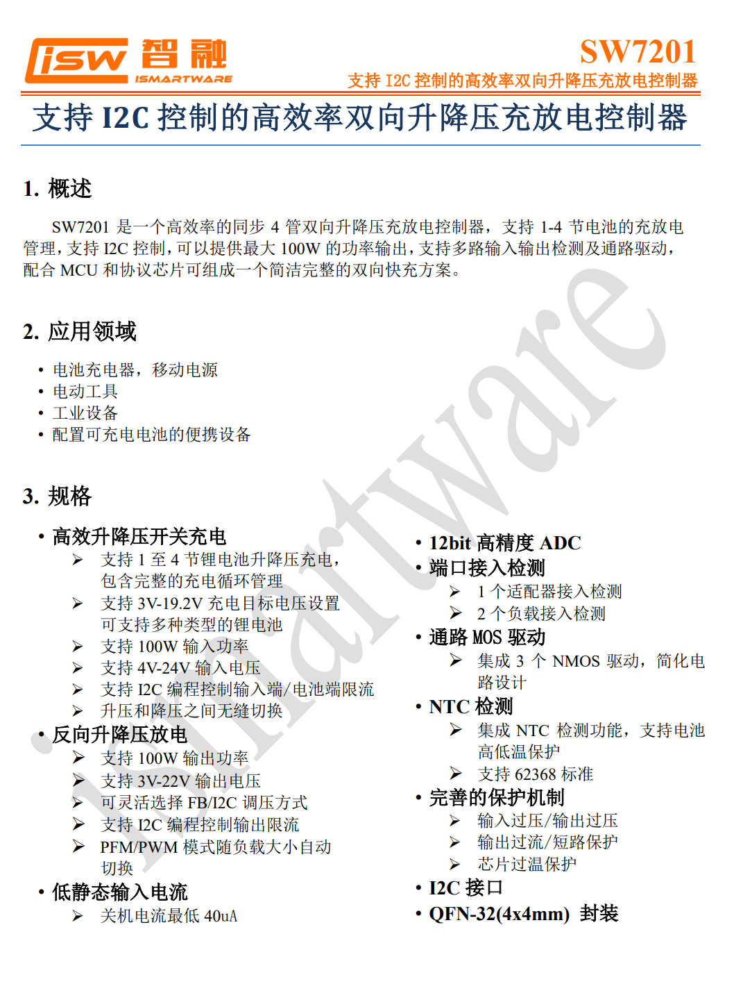
The synchronous buck-boost controller is from iSmartWare, model SW7201. It is a high-efficiency, synchronous four-switch bidirectional buck-boost charge and discharge controller. It supports charging and discharging management for 1-4 series batteries, I2C control, and can deliver a maximum output power of 100W. It supports multi-input/output detection and pass-through driving. When paired with an MCU and protocol chip, it forms a simple and complete bidirectional fast charging solution.
Here is the information about iSmartWare SW7201.
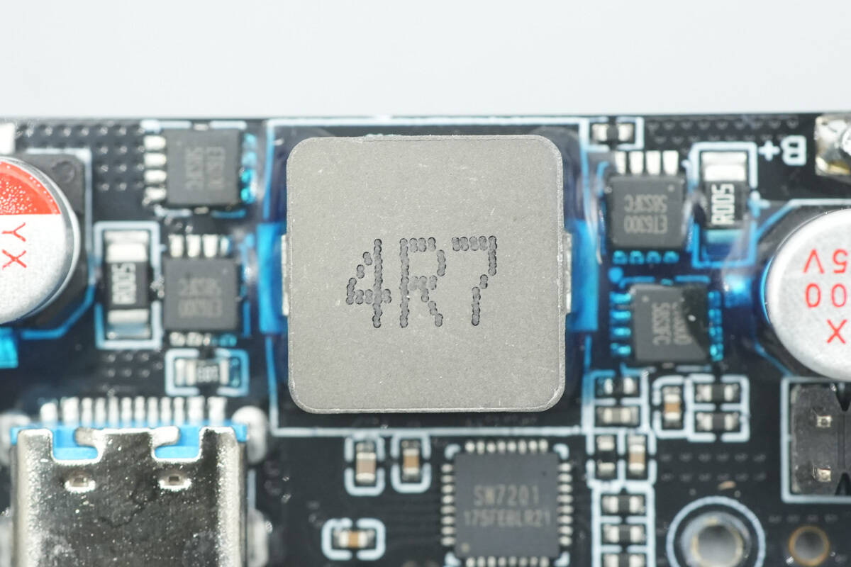
Close-up of the synchronous buck-boost alloy inductor.
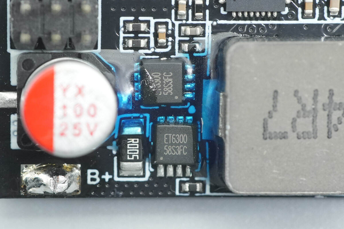
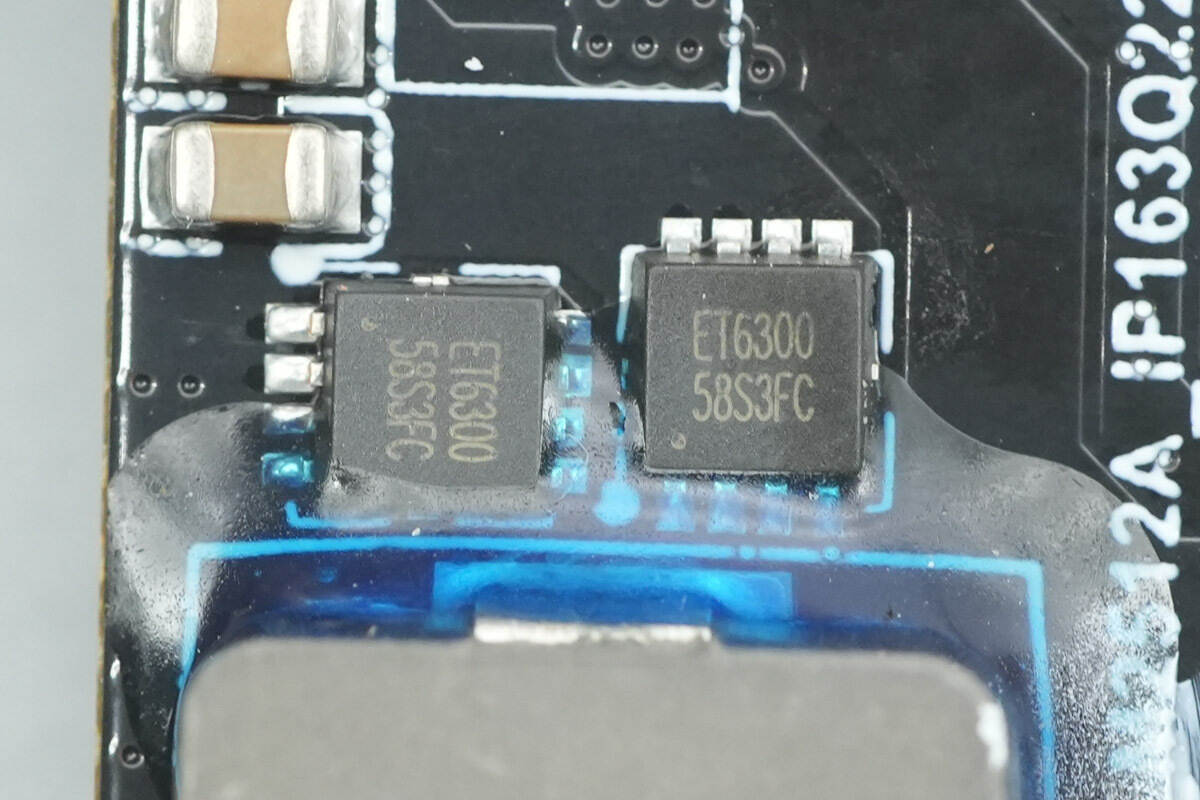
The two synchronous buck-boost MOSFETs are from Eternal, model ET6300. These are NMOS transistors with a voltage rating of 30V and a conduction resistance of 7.9mΩ. They come in a PDFN 3.3×3.3 package.
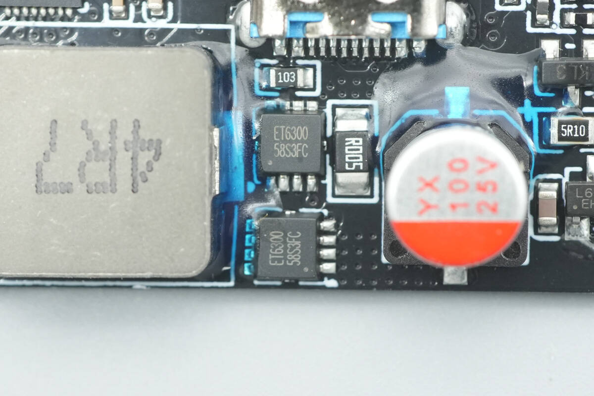
The other two synchronous buck-boost MOSFETs also have the model ET6300, and together with the first two, they form an H-bridge configuration.
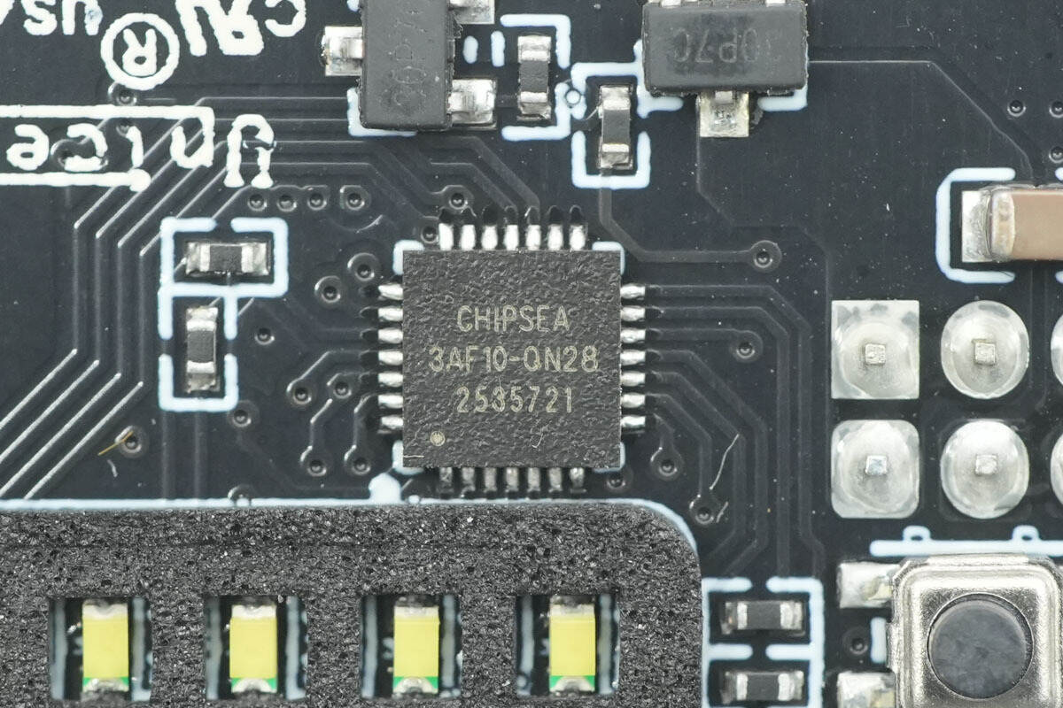
The protocol chip is from Chipsea, model CSU3AF10. It is a USB-C controller that supports USB Type-C and PD3.0 fast charging protocols. The CSU3AF10 integrates an 8-bit RISC core, 32K×16-bit FLASH, and 2K SRAM, and supports two independent Type-C ports. It is compatible with QC4, Huawei SCP, FCP, Samsung AFC fast charging protocols, as well as a variety of other fast charging standards.
The CSU3AF10 also supports external NTC overheat detection and is available in QFN28/QFN24 packages. It is suitable for fast charging power supplies, hubs, and docking applications, and additionally supports USBPD 3.1, UFCS, and other fast charging protocols.
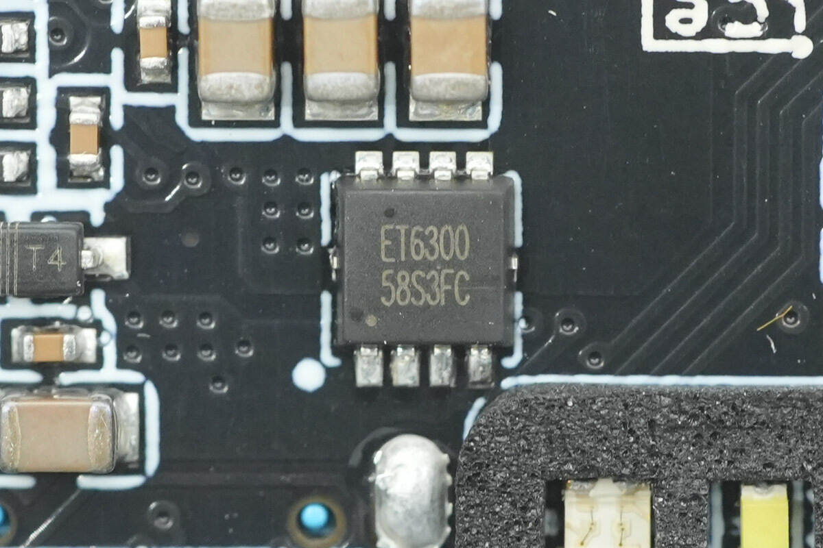
The VBUS MOSFET used for the USB-C interface is also the ET6300 model.
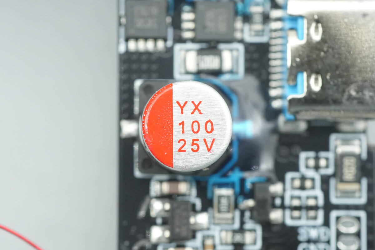
The solid capacitor is from YX, with a specification of 25V 100μF.
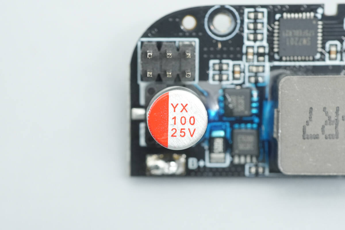
The other capacitor has the same specifications: 25V 100μF.
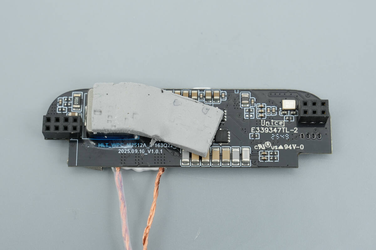
The wireless charging control PCB is equipped with a large-area thermal pad for heat dissipation.
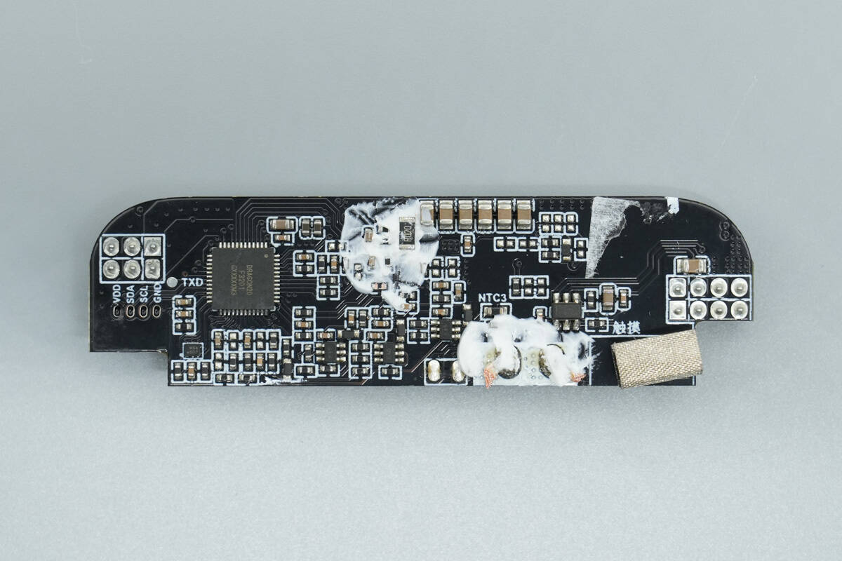
After removing the thermal pad, the front of the PCB reveals the wireless charging master control chip, the touch chip, and the authentication chip.
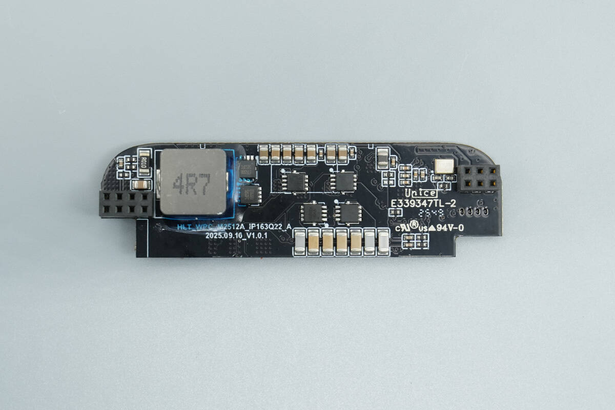
The back of the PCB features a boost chip, boost MOSFETs, an inductor, and wireless charging power MOSFETs.
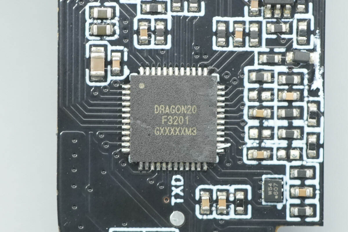
The wireless charging master control chip is marked with DRAGON20 and comes in a QFN48 package.
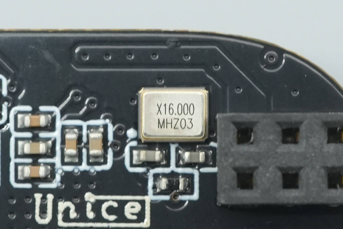
Close-up of the external 16.000 MHz passive crystal oscillator for the wireless charging master control chip.
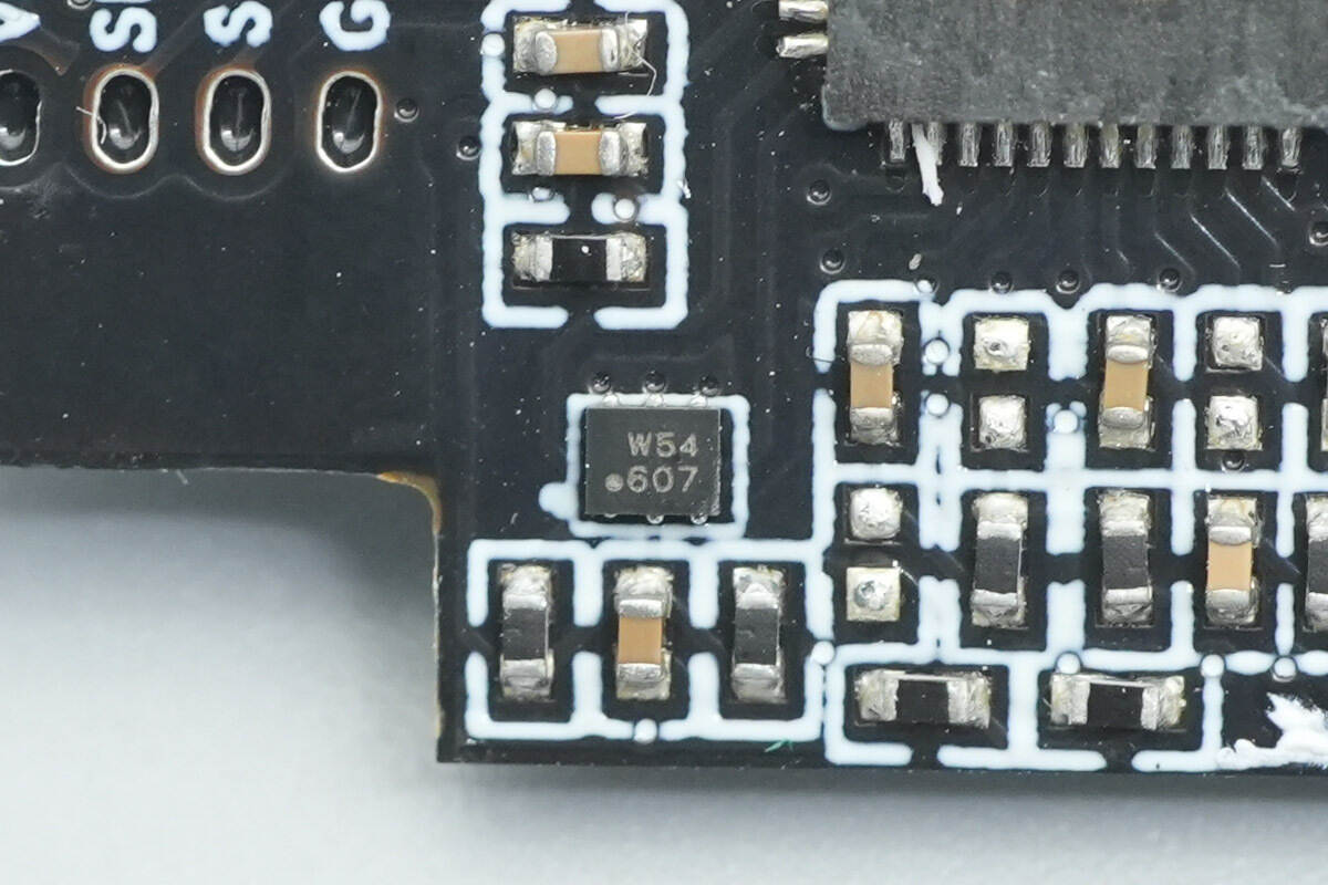
The authentication chip is from TONGXIN MICRO, marked with W54607. It is a WPC Qi-compliant authentication chip, providing users with a reliable security certification solution to ensure the authenticity and safety of the product.
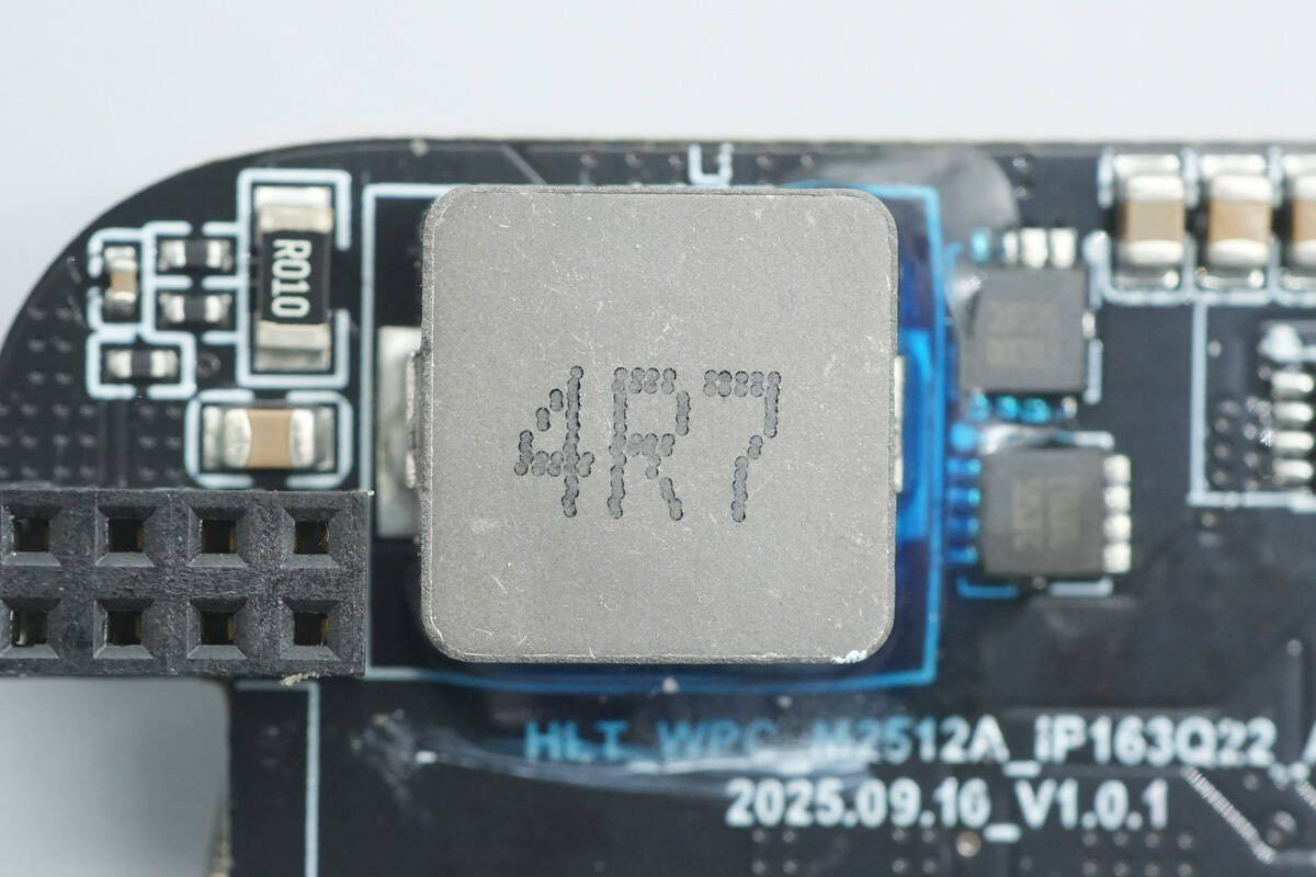
Close-up of the alloy boost inductor.
The two boost MOSFETs adjacent to the authentication chip are also model ET6300.
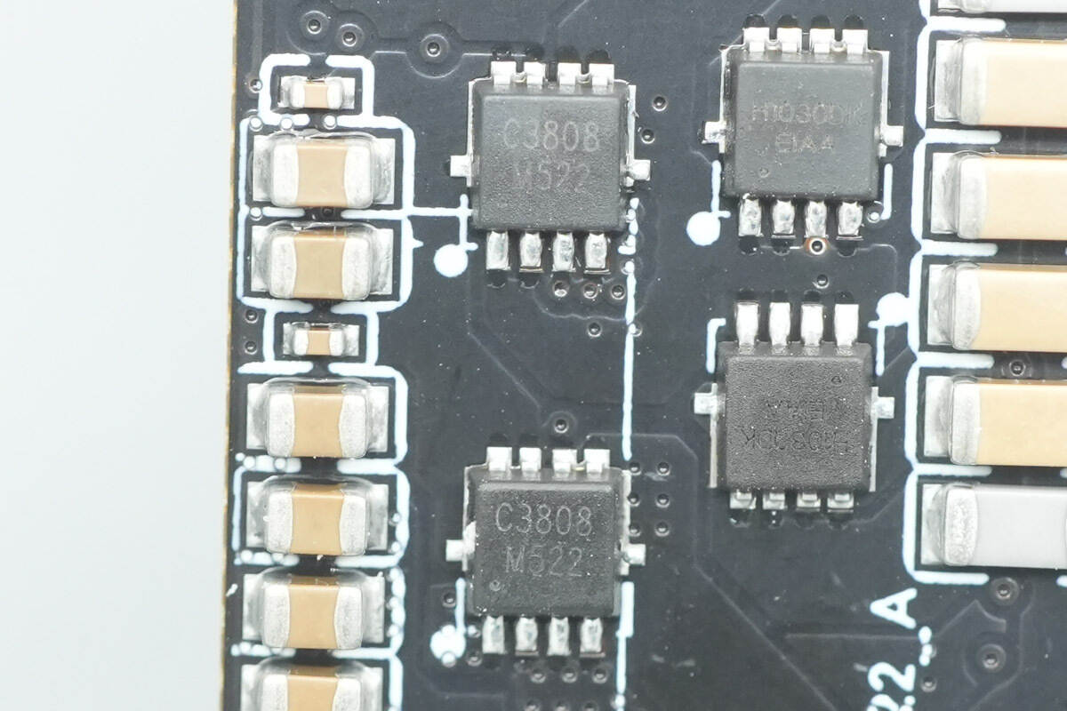
The two wireless charging power MOSFETs are marked with C3808.
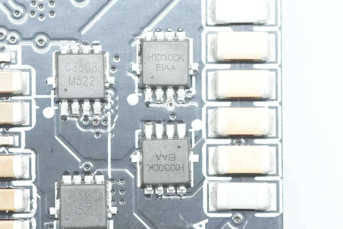
The MOSFETs used for switching the resonant capacitors are marked with H1030DK.
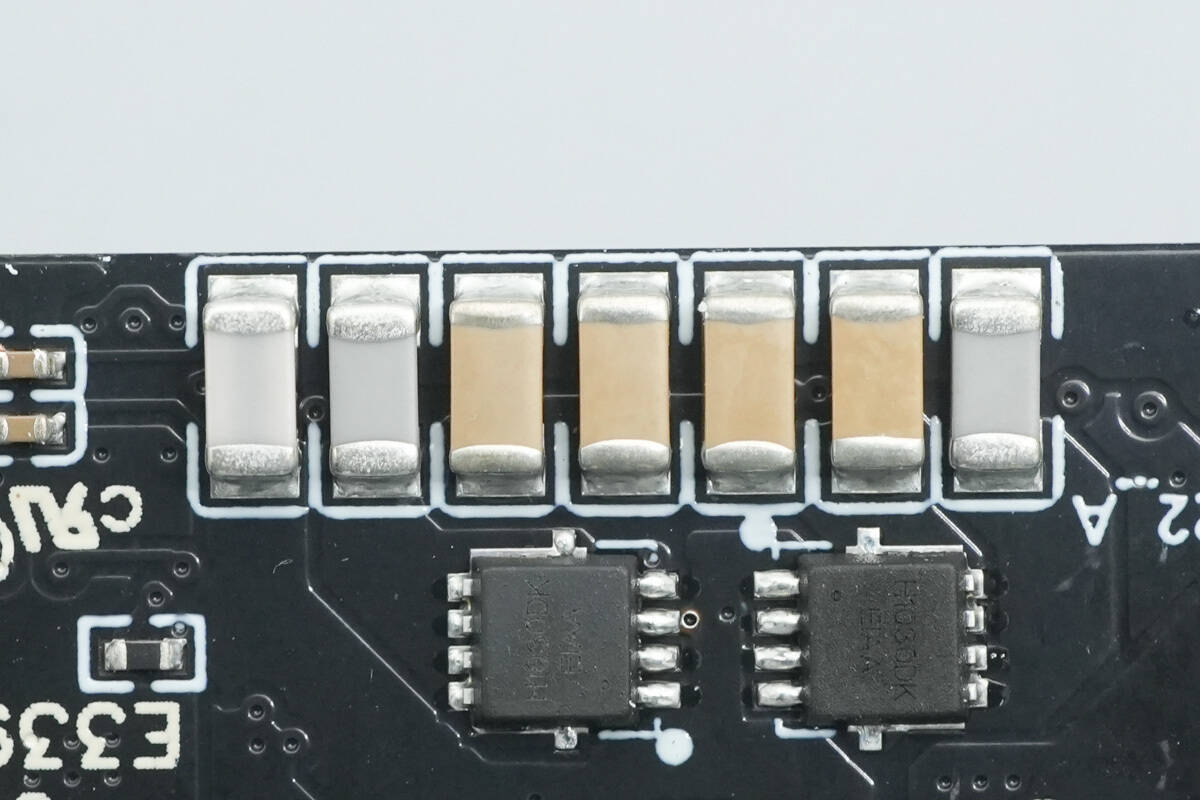
Close-up of the NPO resonant capacitors.
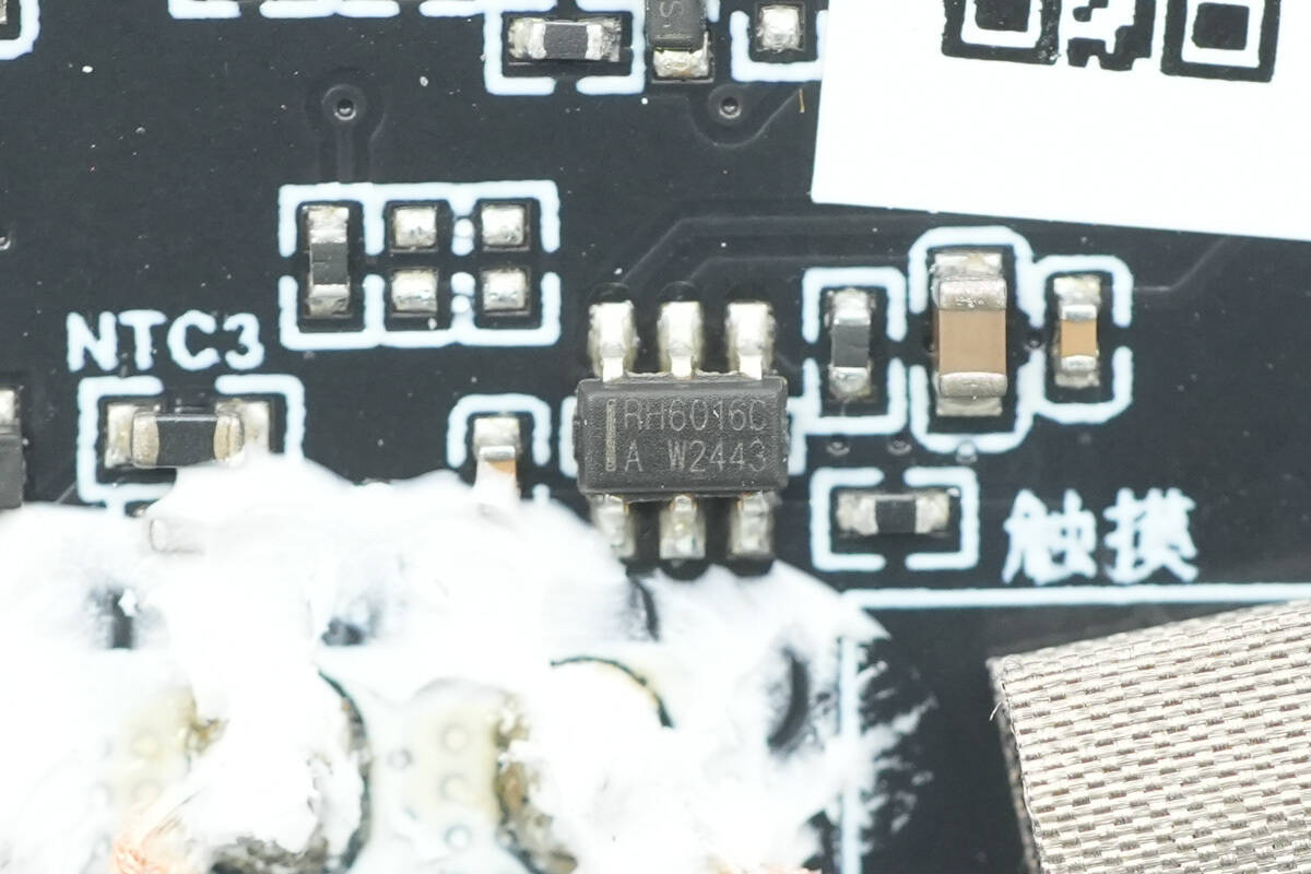
The touch chip is from RONGHE, model RH6016. It is a single-channel capacitive touch sensing control switch IC with an integrated voltage regulator module. This chip can replace traditional mechanical switches and comes in an SOT23-6 package.
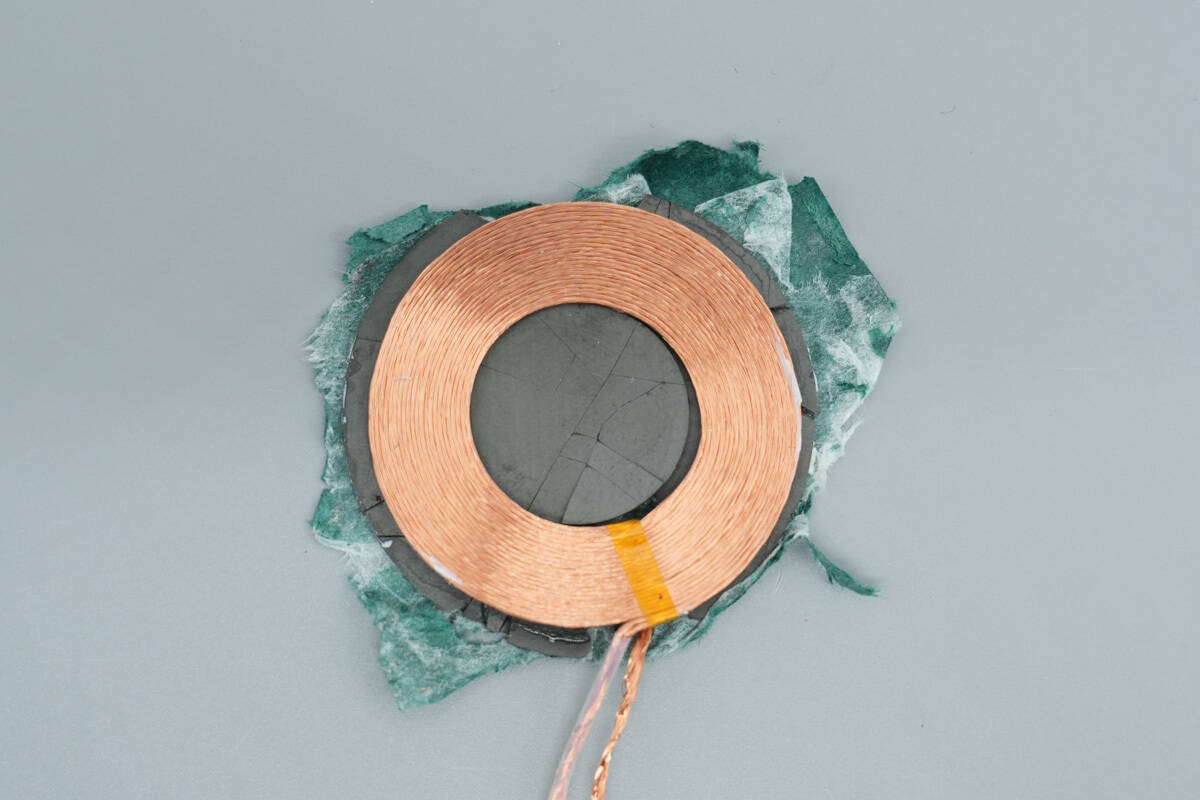
The wireless charging coil is wound with Litz wire, and the backside is covered with kraft paper for insulation.
Well, those are all components of the Momax 10000mAh Semi-Solid State Magnetic Power Bank.
Summary of ChargerLAB
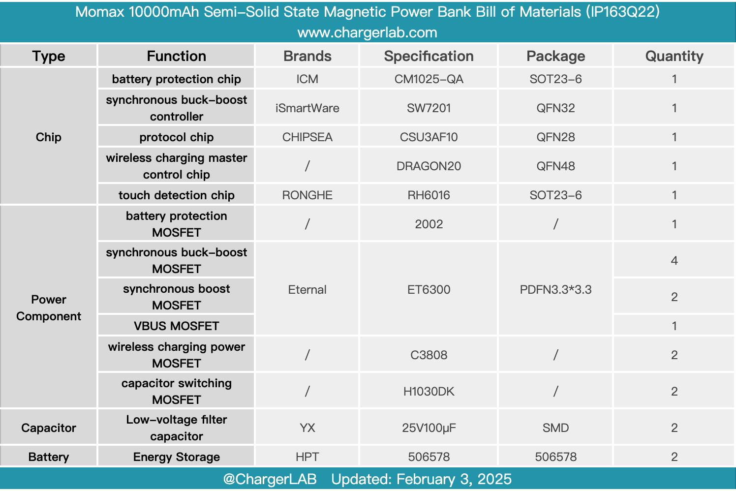
Here is the component list of the Momax 10000mAh Semi-Solid State Magnetic Power Bank for your convenience.
It features a flat rectangular body with rounded corners at the bottom, specifically designed to fit the iPhone 17 Pro Max. The battery capacity is 10,000mAh, and it is compatible with PD3.0, QC3.0, and other protocols. It has also passed the latest Qi2.2 certification and supports MPP 25W wireless fast charging. Equipped with a USB-C port, it supports both 30W input and output.
After taking it apart, we found that the PCBA module adopts a stacked structure to improve space utilization. The battery pack consists of two series of HPT half-solid-state battery cells, with each cell having a capacity of 5000mAh. The battery protection system uses the iCM CM1025-QA chip in conjunction with a protection MOSFET, providing overcharge, over-discharge, and overcurrent safety protection for the cells.
The wired fast charging uses the iSmartWare SW7201 synchronous buck-boost controller, paired with four Eternal ET6300 MOSFETs to form an H-bridge power stage. The protocol chip is the Chipsea CSU3AF10, supporting PD3.0 and various other fast charging protocols. The wireless charging module features an independent PCB, equipped with the DRAGON20 wireless master control chip, and integrates the TONGXIN MICRO W54607 authentication chip to meet Qi2.2 certification requirements, further enhancing the compatibility and safety of wireless charging.
Related Articles:
1. Teardown of Aohai Technology 3200W 80 PLUS Titanium Server Power Supply (AH-CRPS3200A1A)
2. Teardown of CUKTECH 6 90W Mini GaN Charger (AD653)
3. Teardown of Xiaomi 140W 8-in-1 Desktop Charging Station (XMCDZ-03QM)