Introduction
The Meizu PANDAER 66W Vertical Air-cooled Wireless Charger is inspired by Nordic architecture, featuring a minimalist design. With a 65° tilt angle, it provides an optimal experience for charging while using the device. The charger includes dual coils, allowing it to charge both horizontally and vertically. Equipped with an internal cooling fan, the charger utilizes a three-dimensional heat dissipation system. It also comes with height-adjustable pads for better compatibility with a variety of devices. Let’s take a closer look at the design of this wireless charging accessory.
Product Appearance
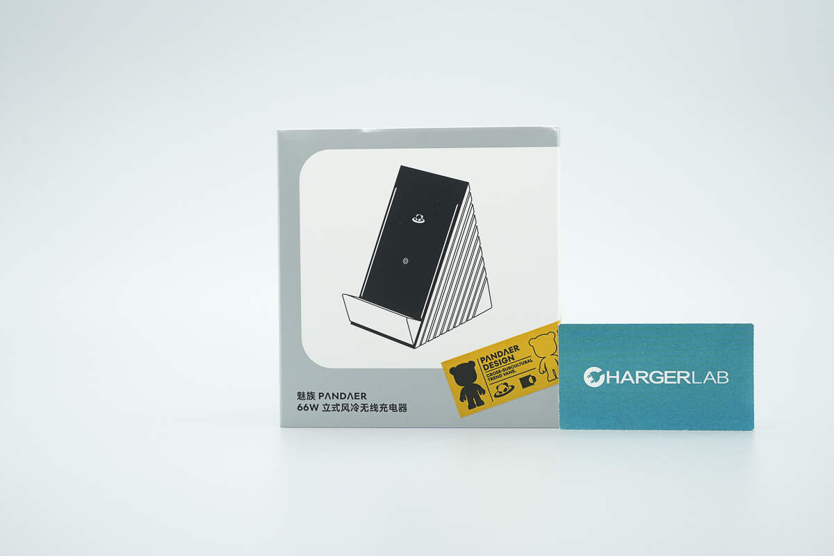
The front of the packaging features a product illustration and the name.
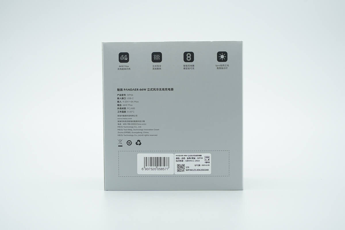
The back of the packaging displays key selling points and product specifications.
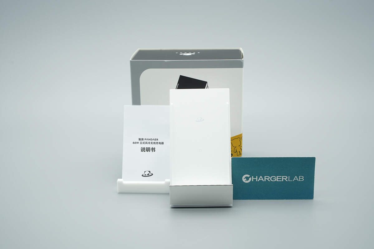
The package includes the wireless charger and an instruction manual.
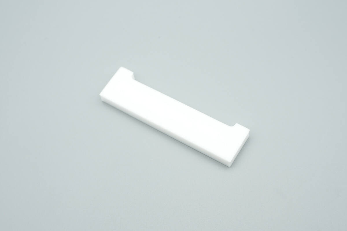
It comes with a height-adjustable pad for better compatibility with more device models.
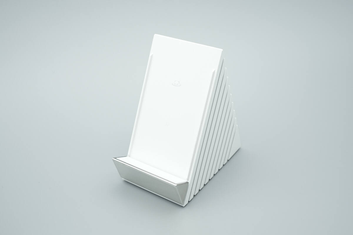
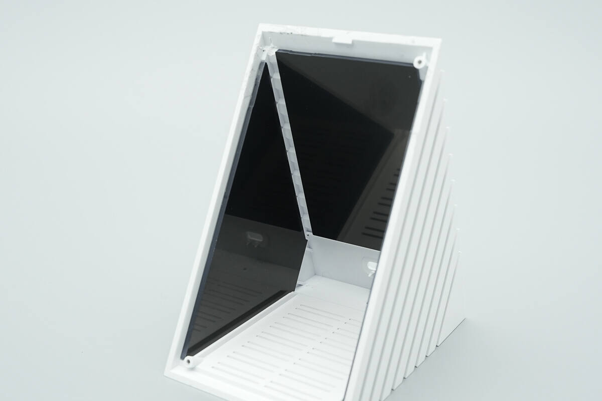
It is inspired by Nordic architecture, featuring an exceptionally minimalist design.
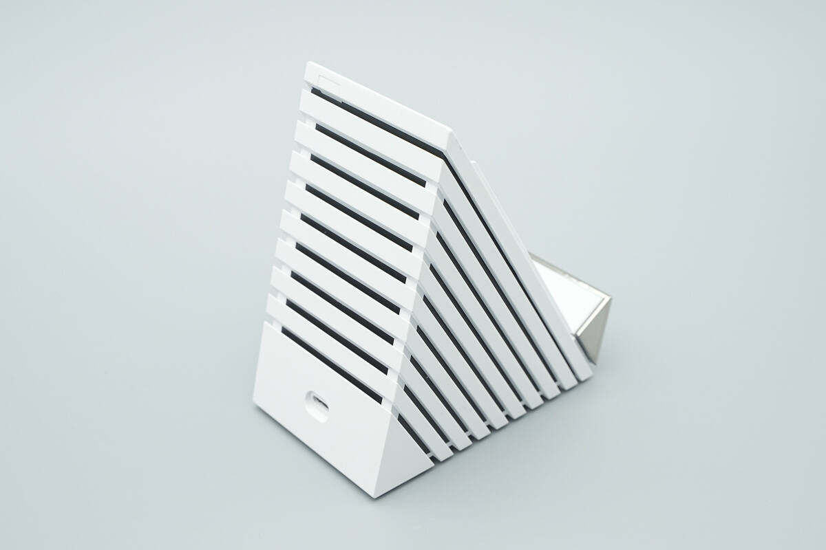
The sides and back of the device feature grilles, further enhancing the product's distinctive identity.
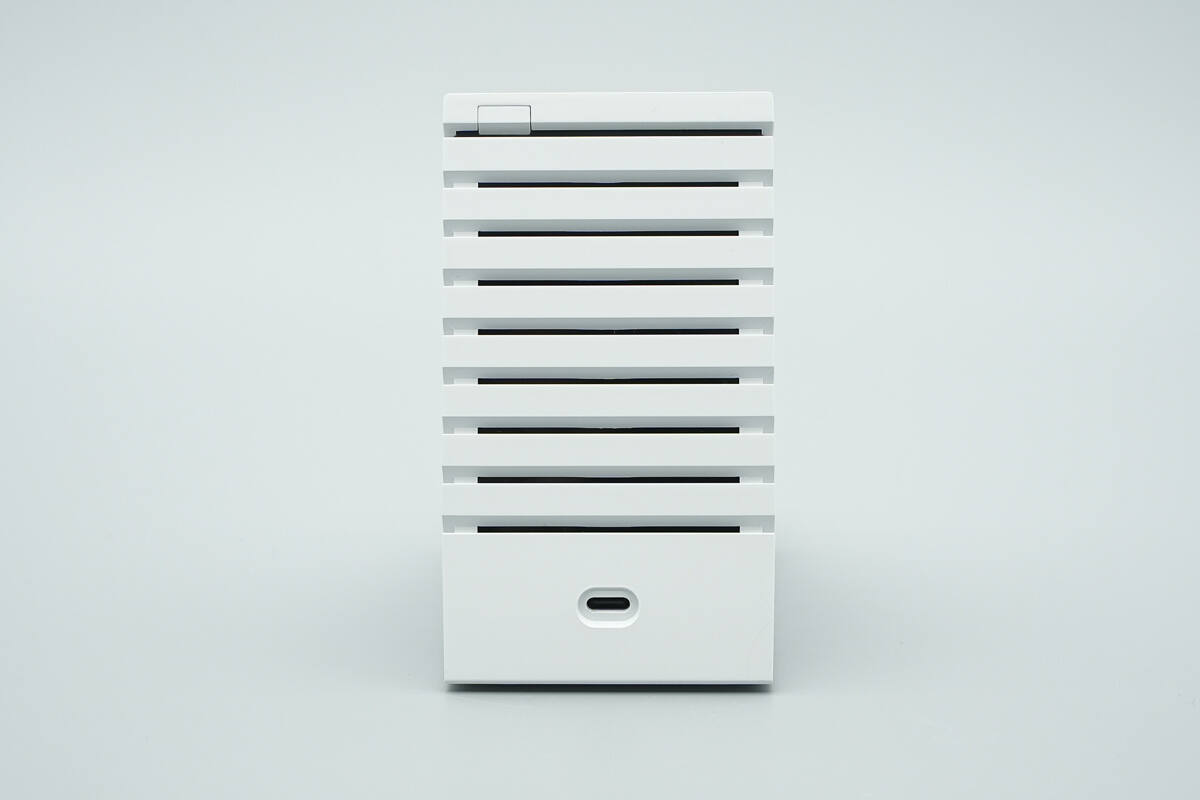
The bottom of the back has a USB-C port, with a touch control function located next to the port.
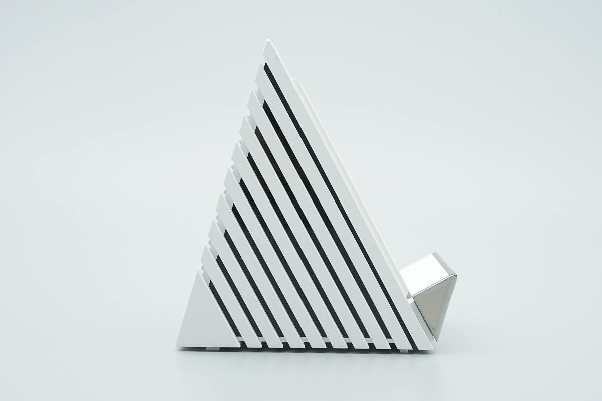
The angled design is ergonomically crafted for a more comfortable user experience.
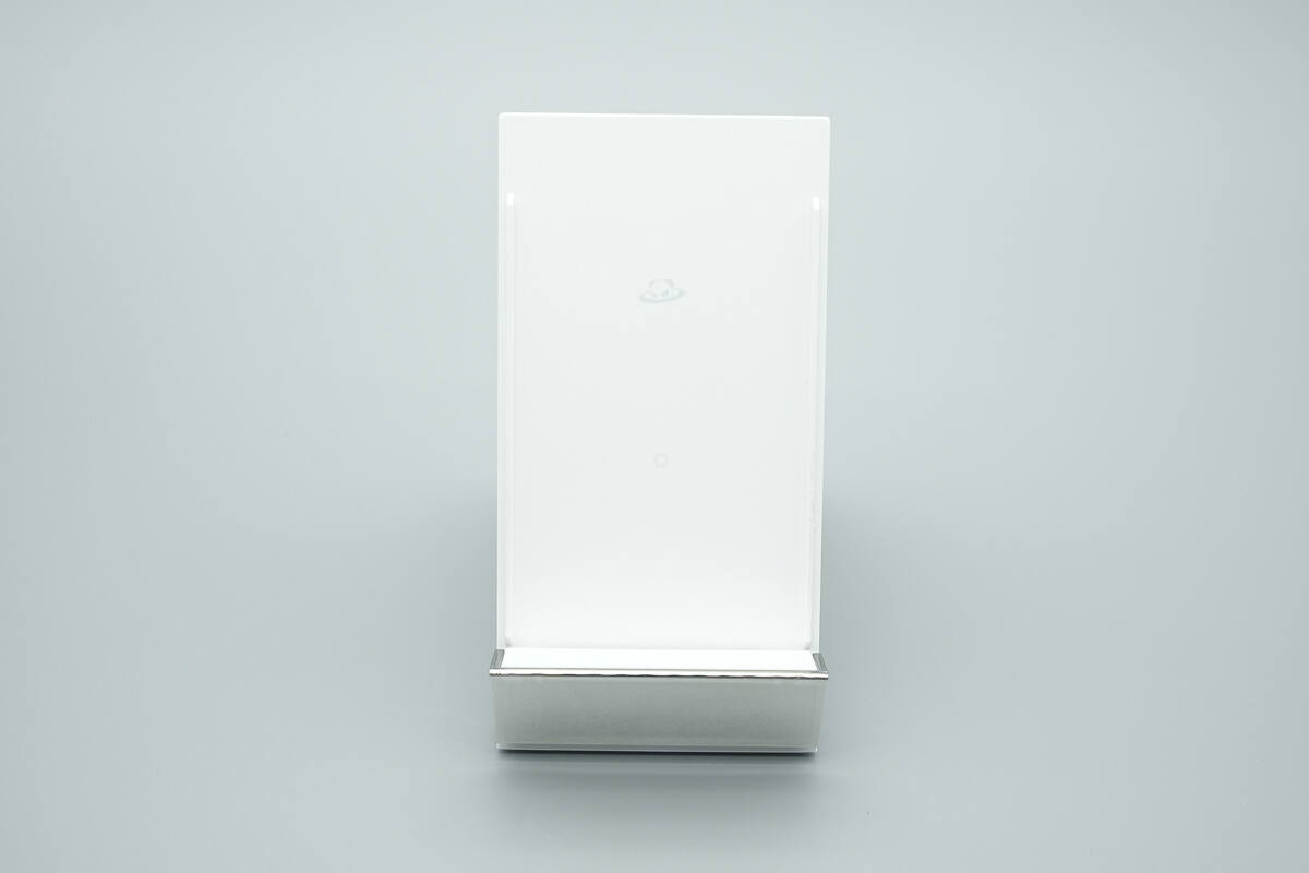
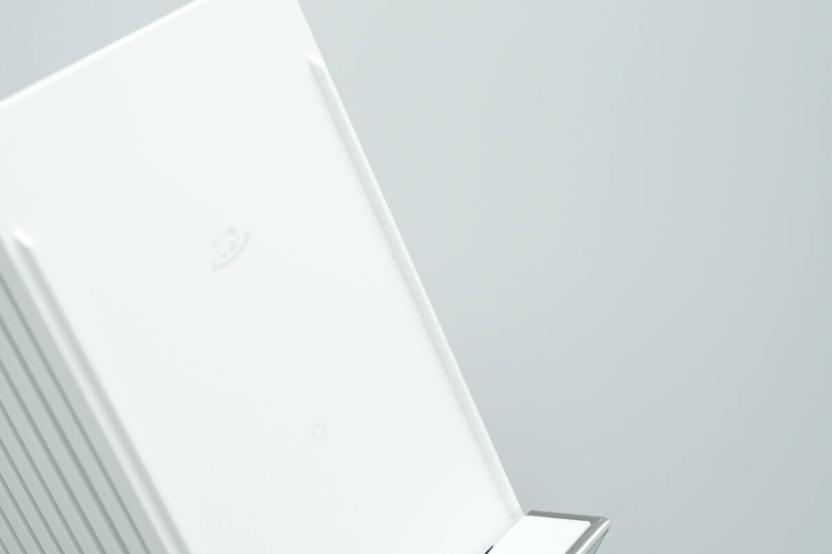
The wireless charging panel is marked with the PANDAER logo and the wireless charging area indicator.
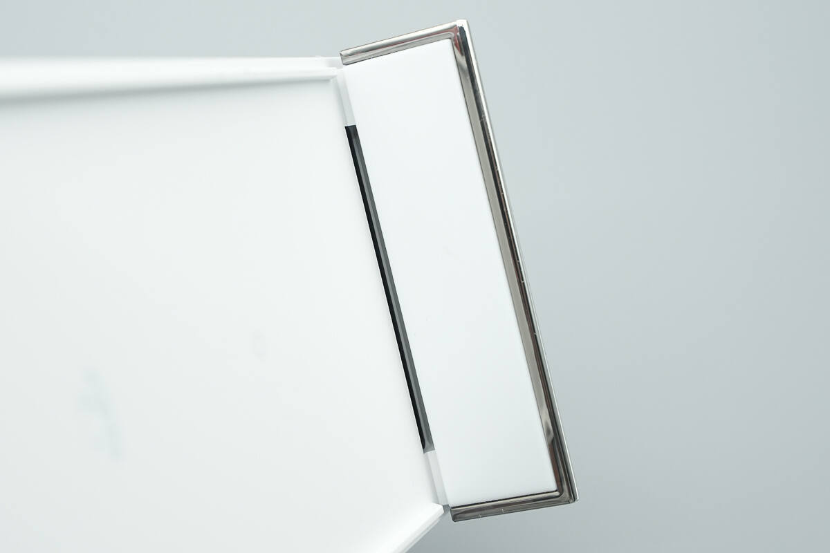
The support platform is equipped with an air outlet.
The sides of the wireless charging panel are raised, naturally forming an airflow channel when a phone is placed on it. This, combined with the bottom air outlet, creates a three-dimensional heat dissipation system.
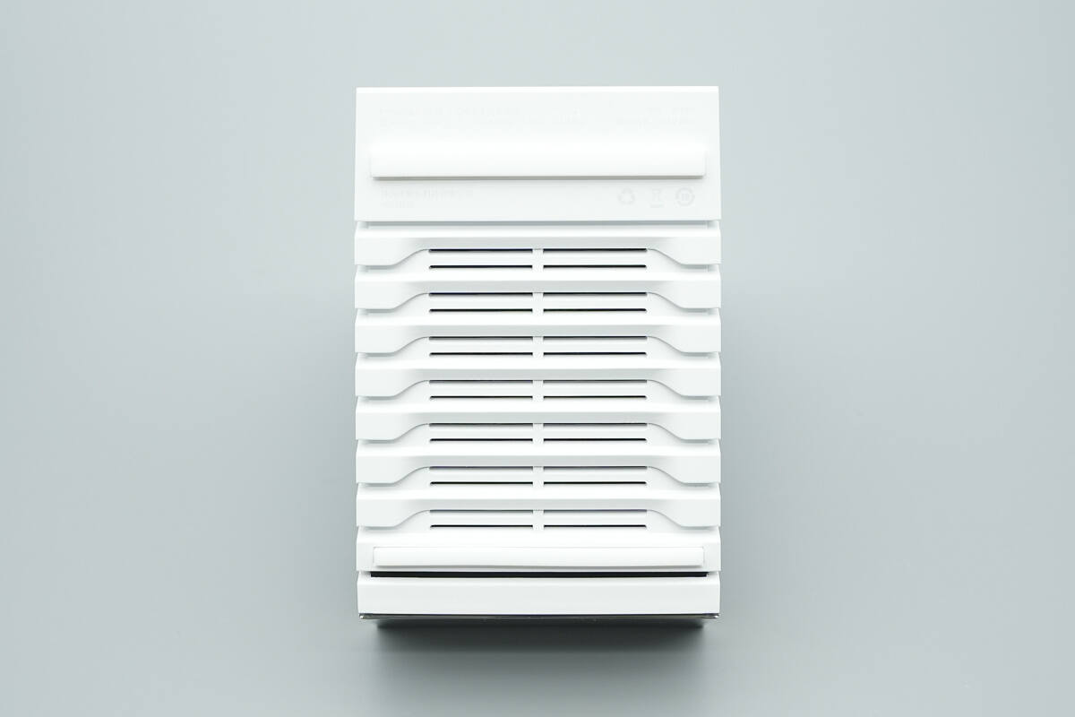
The bottom features non-slip pads, with a grille air intake located at the center.
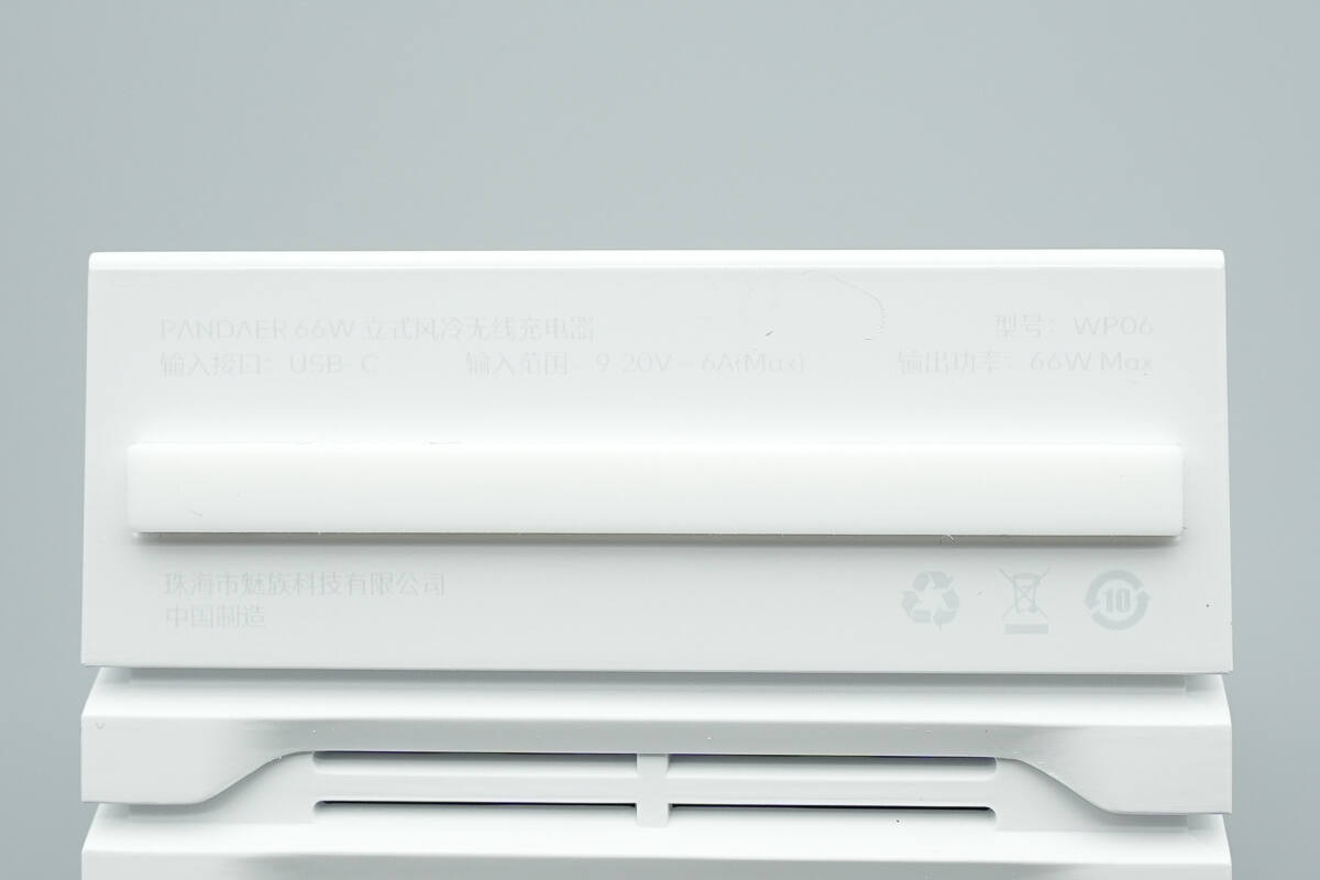
Model: WP06
Input Interface: USB-C
Input Range: 9-20V 6A (Max)
Output Power: 66W Max
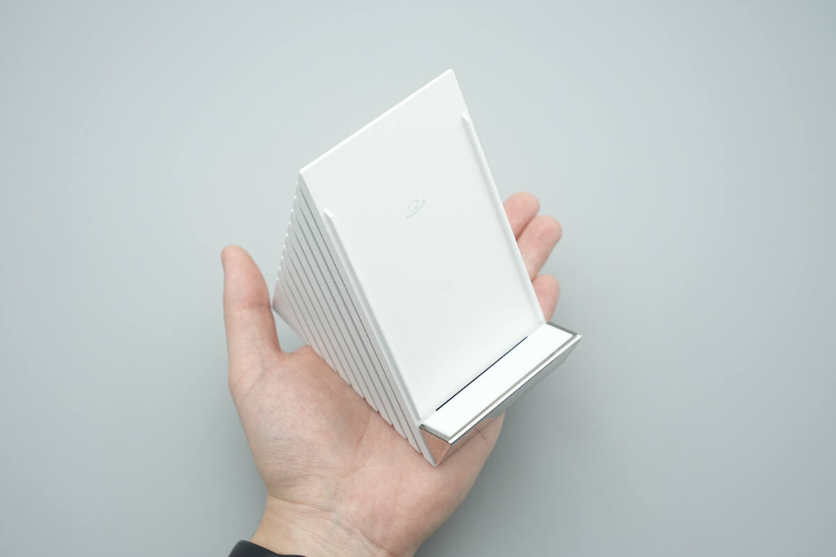
That's how big it is in the hand.
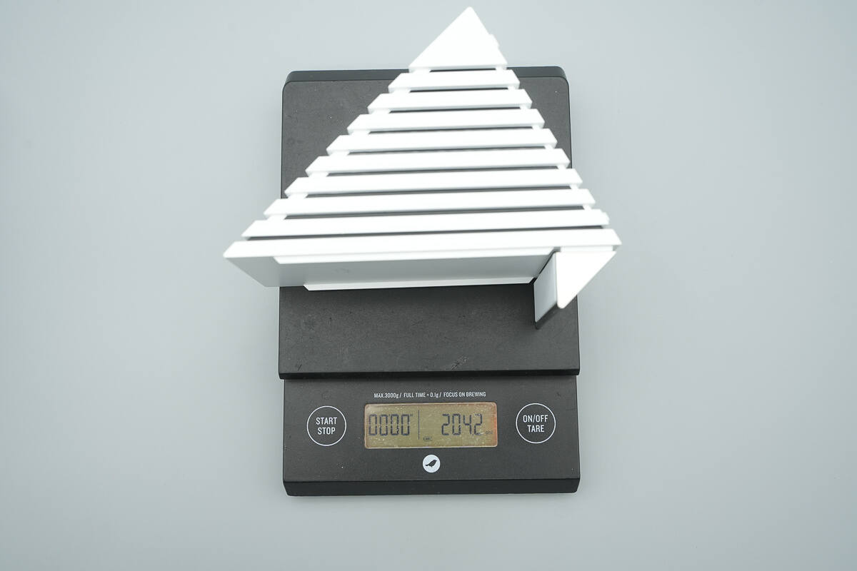
The weight is about 204 g (7.2 oz).
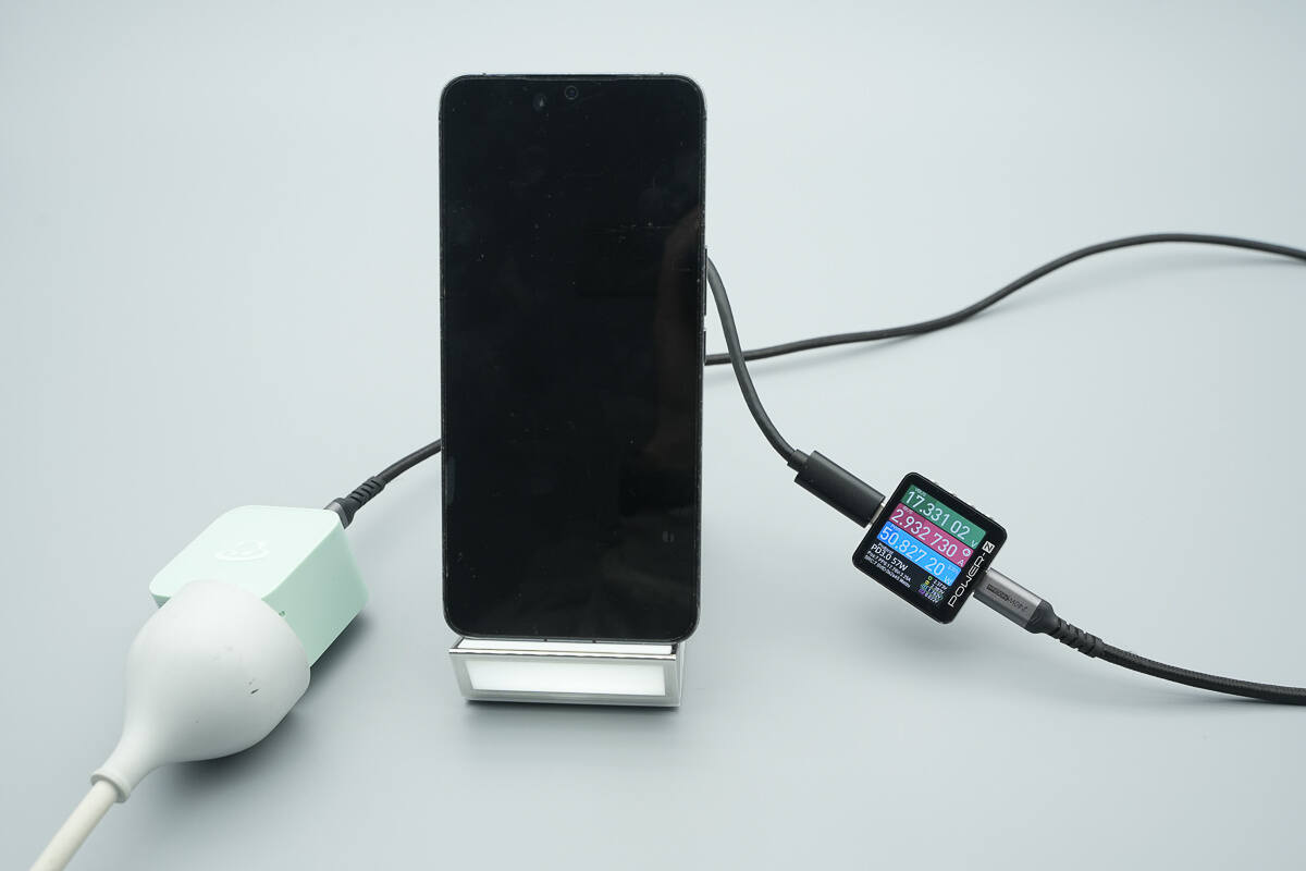
When used to charge the MEIZU 20 Pro, the measured wireless charging power is about 50.8W.
Teardown
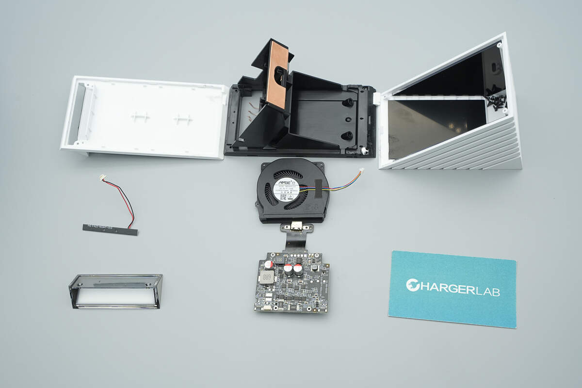
Next, let's take it apart to see its internal components and structure.
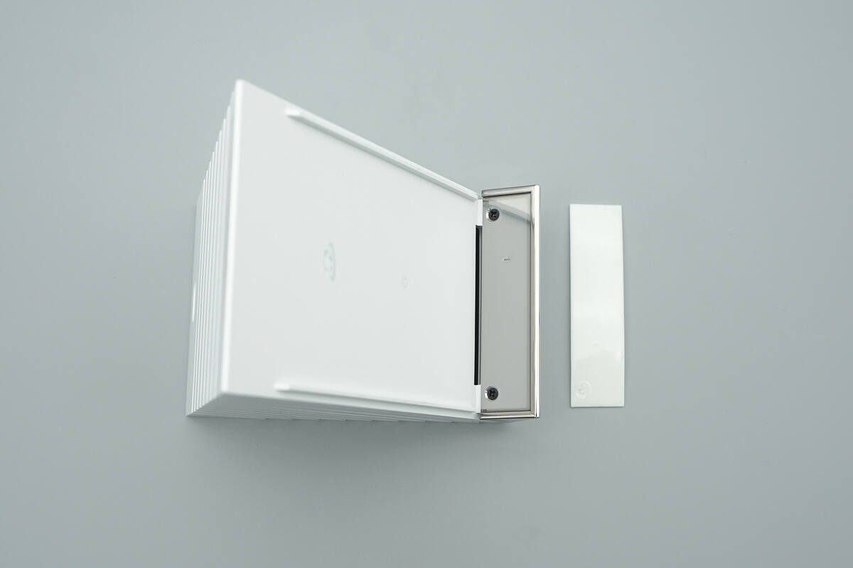
Peeling off the protective pad on the support platform reveals hidden screws.
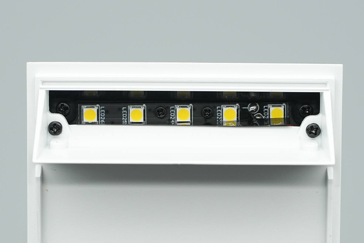
After removing the screws and taking off the cover, you will find the screws and indicator lights inside.
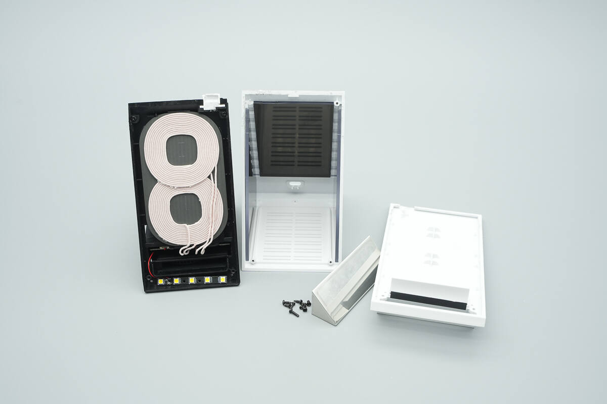
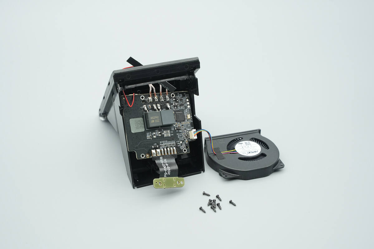
By removing the screws from the bottom and the support platform, you can open the wireless charging panel and take out the internal module.
The interior of the shell features partition plates on both sides and the back, designed to seal the side grilles and increase the airflow volume of the ventilation outlets, thereby enhancing the cooling efficiency.
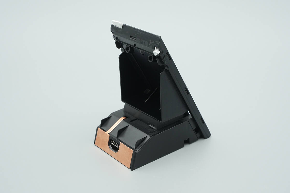
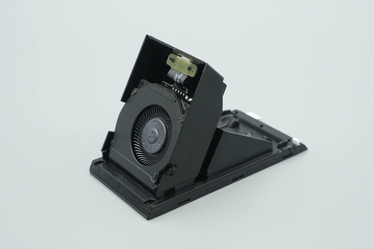
The integrated black plastic stand is used to support and secure the PCBA module and wireless charging coil.
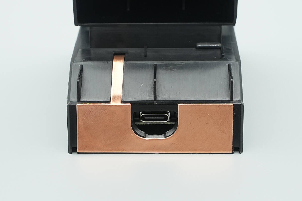
The USB-C interface area is equipped with a thermal copper sheet.
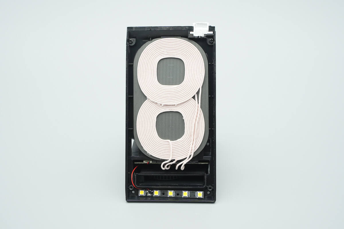
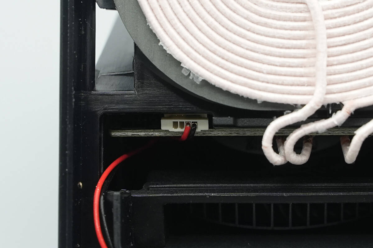
The front end of the stand is equipped with a wireless charging coil and an LED light panel, which is connected to the motherboard via red and black wires.

A heat dissipation fan outlet is located between the coil and the light panel.
A heat dissipation fan outlet is located between the coil and the light panel.
The wireless charging motherboard and the heat dissipation fan are securely fixed at the bottom.
The USB-C socket is fixed using a small board and screws.
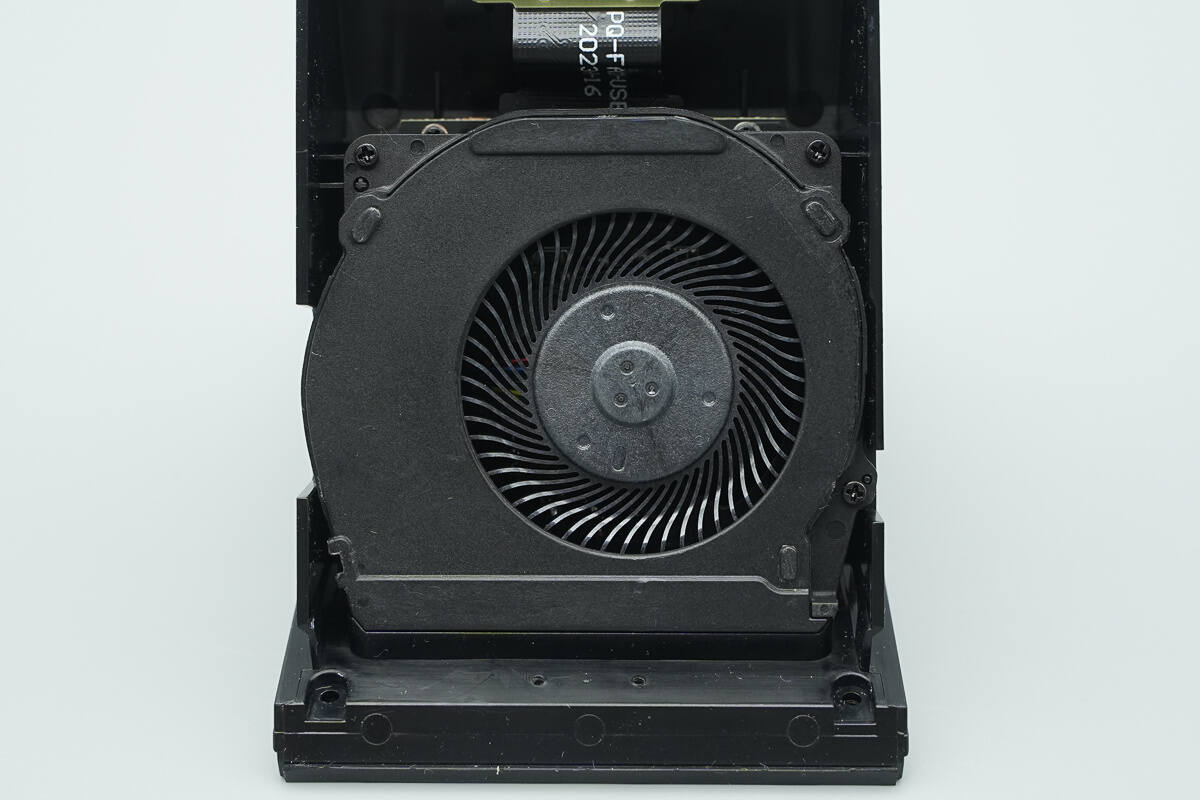
The fan is also secured with screws.
Remove the screws to take out the fan.
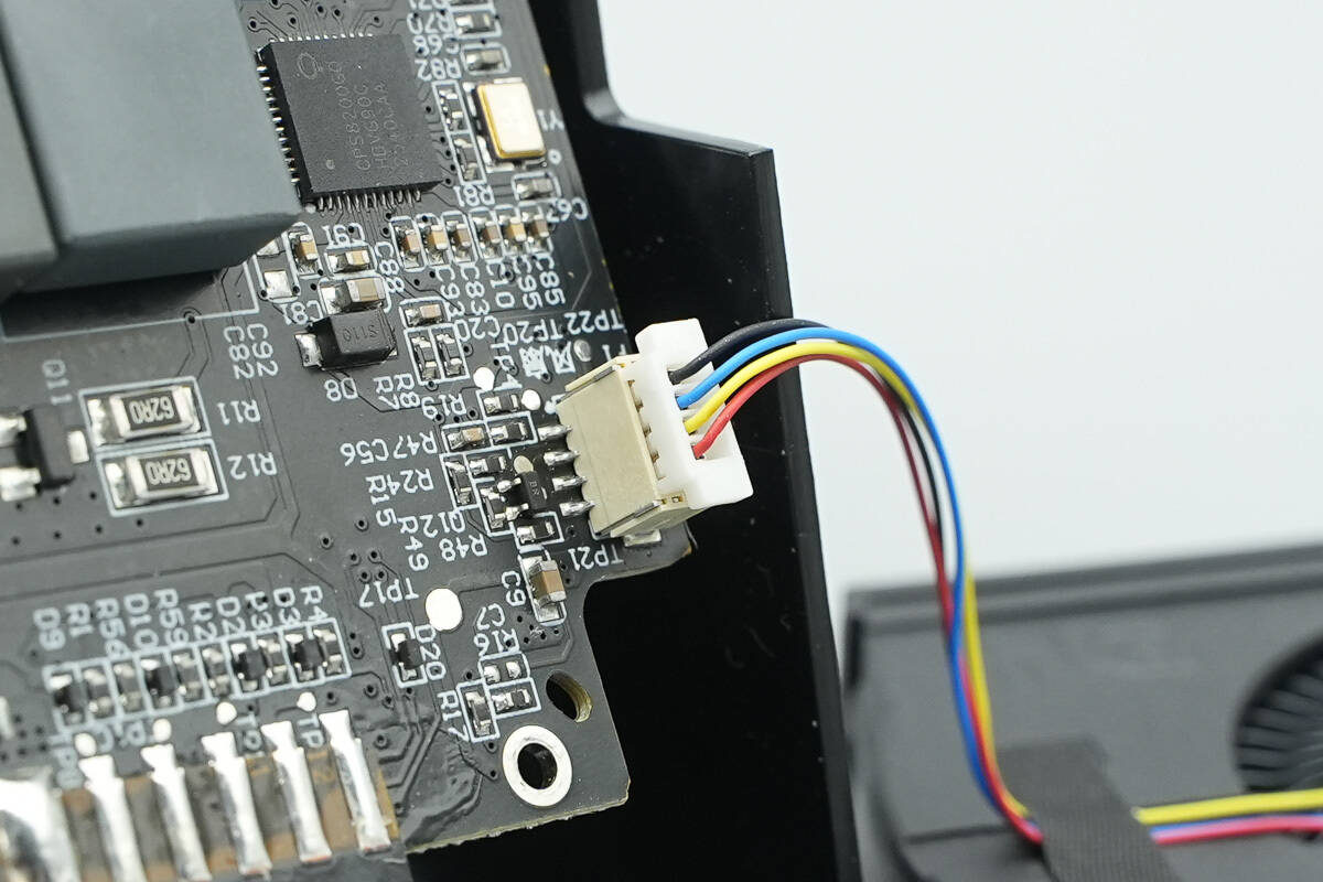
The fan's wiring is connected to the motherboard via a plug-and-play connector.
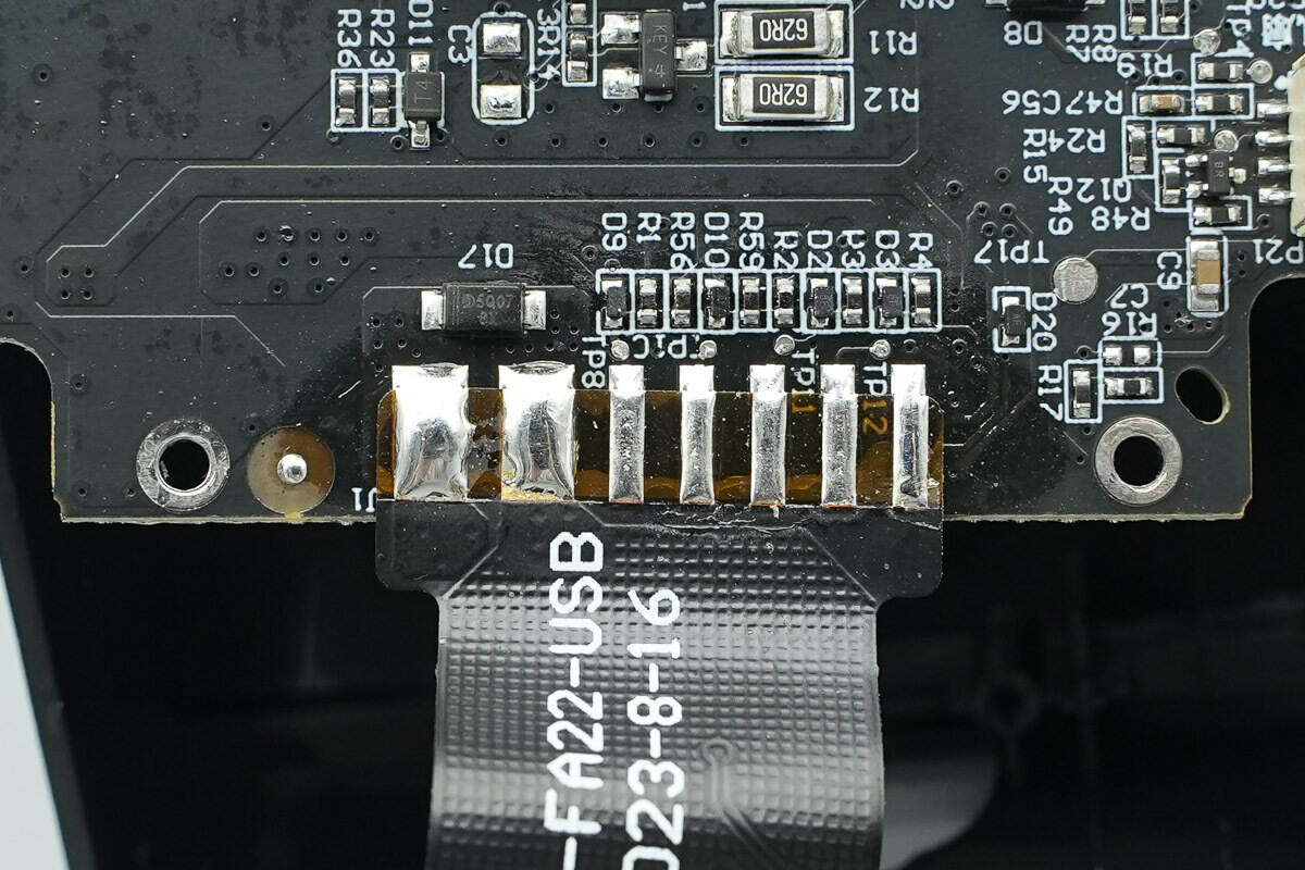
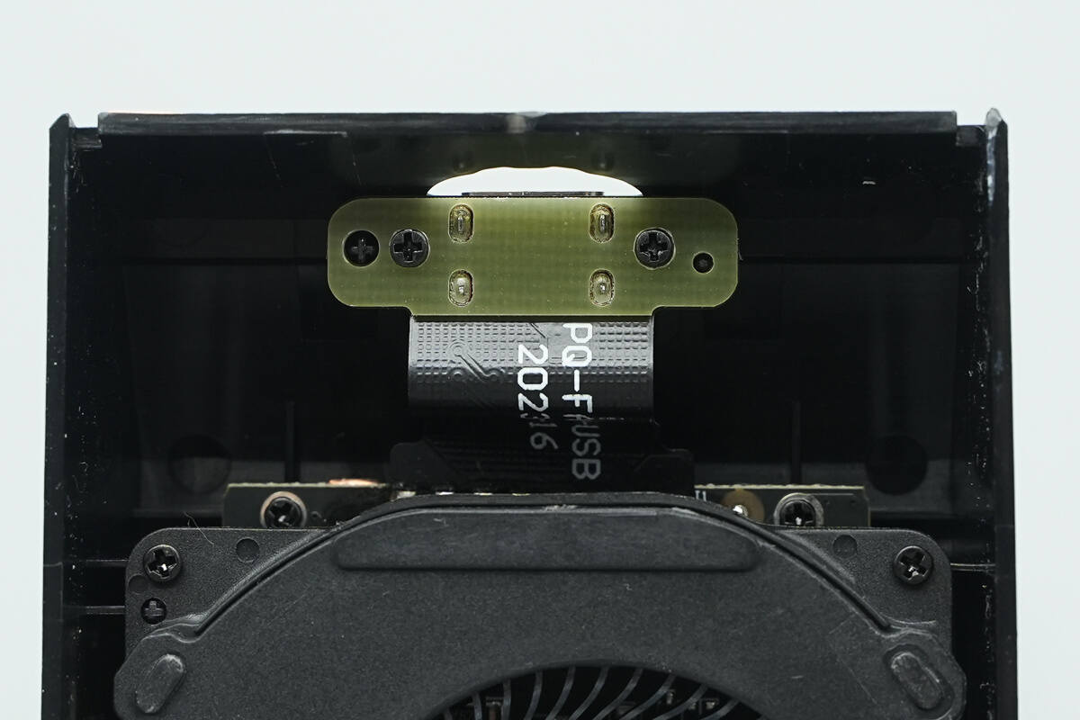
The USB-C socket is connected to the PCBA module via a ribbon cable.
The front of the PCBA module features components such as the MCU, wireless charging power MOSFETs, wireless charging coil-switching MOSFETs, a synchronous buck converter, and solid capacitors.
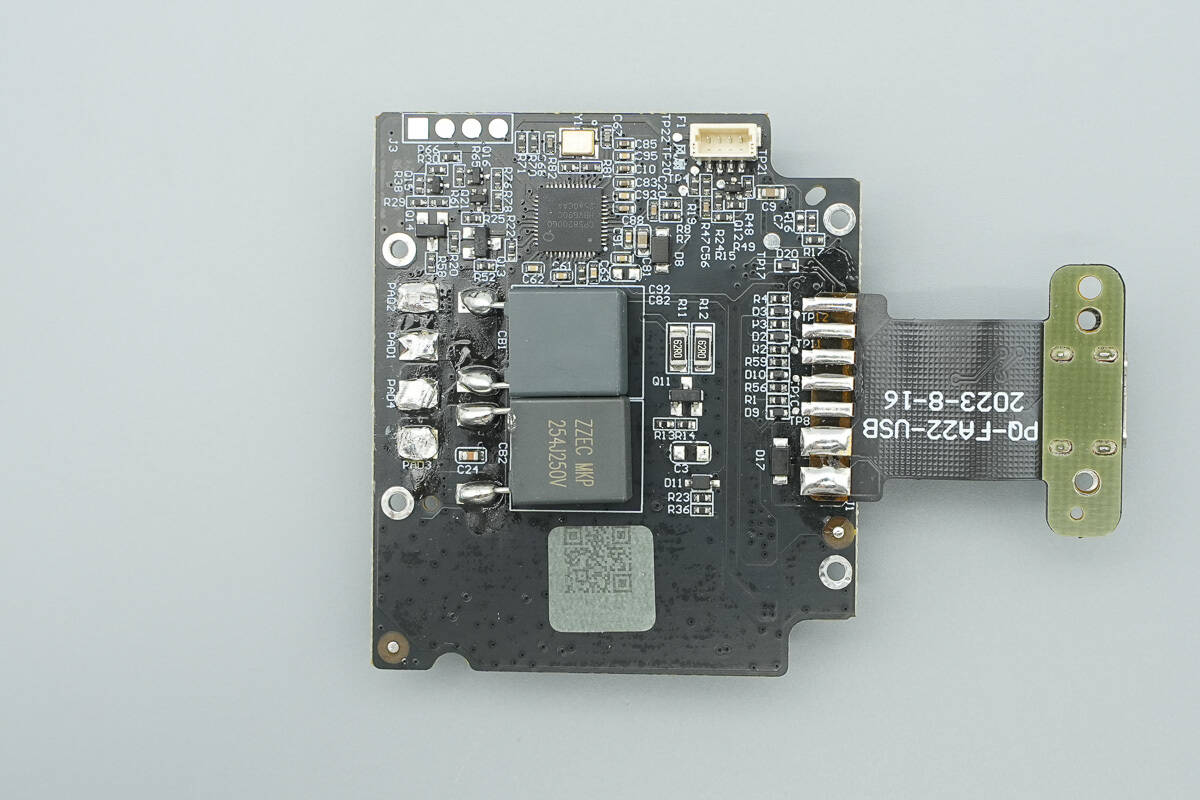
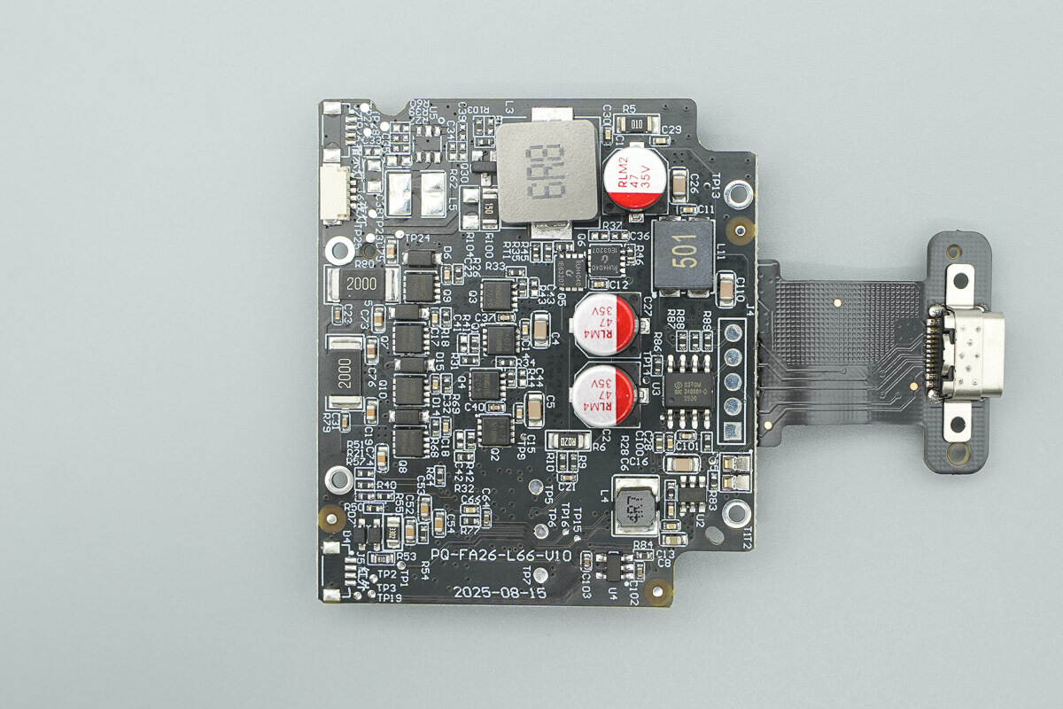
The back of the PCBA module contains the wireless charging master control chip, resonant capacitors, and other components.
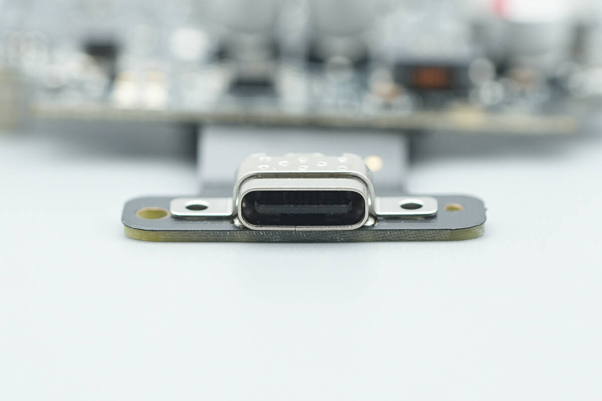
The USB-C socket is reinforced with a steel sheath and spot welding.
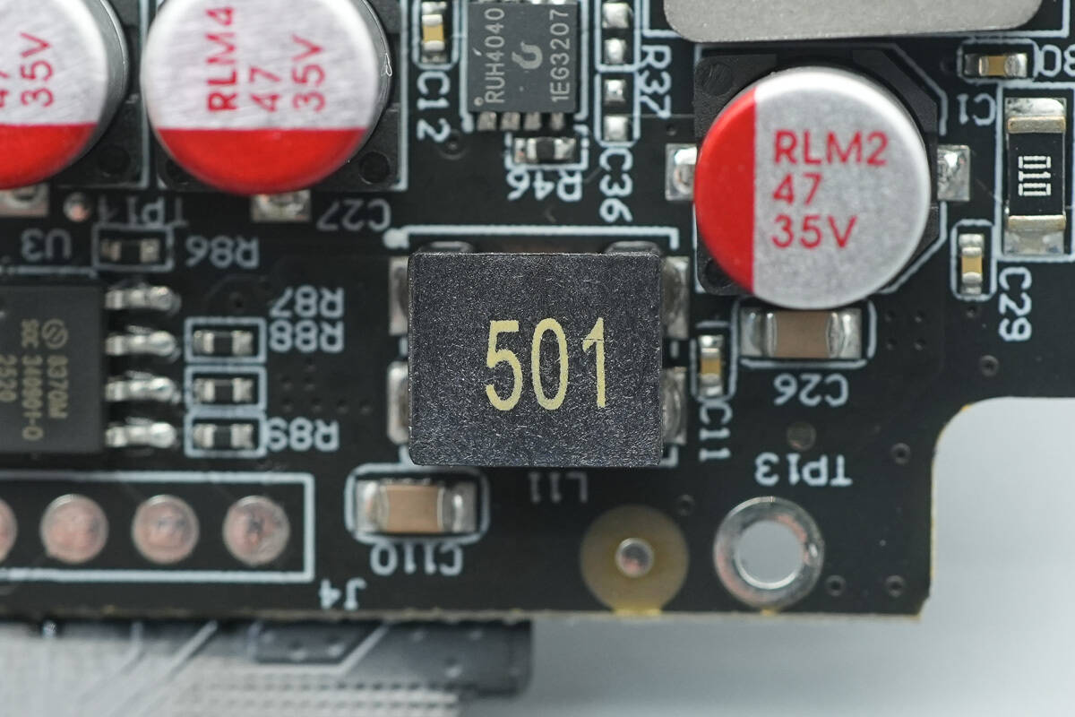
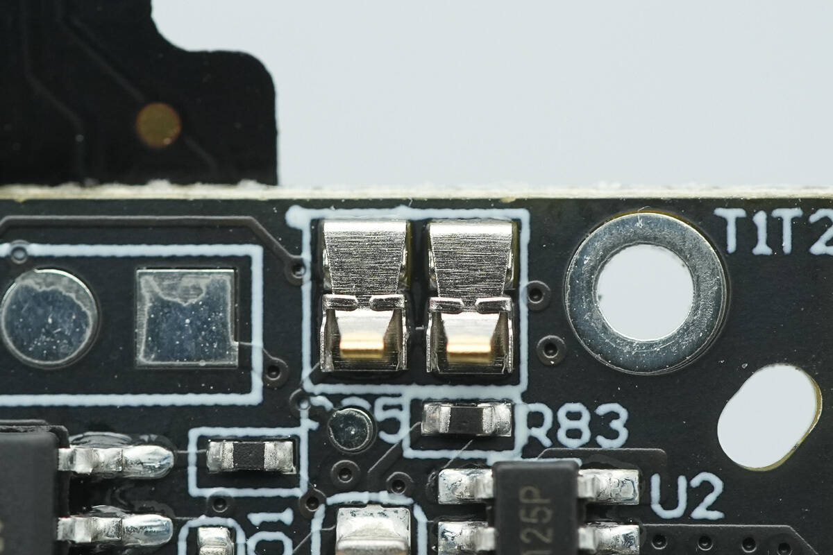
Close-up of the filtering inductor.
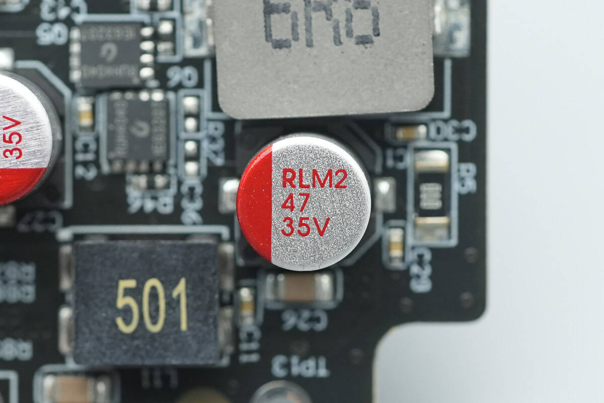
The filtering capacitor has a specification of 35V 47μF.
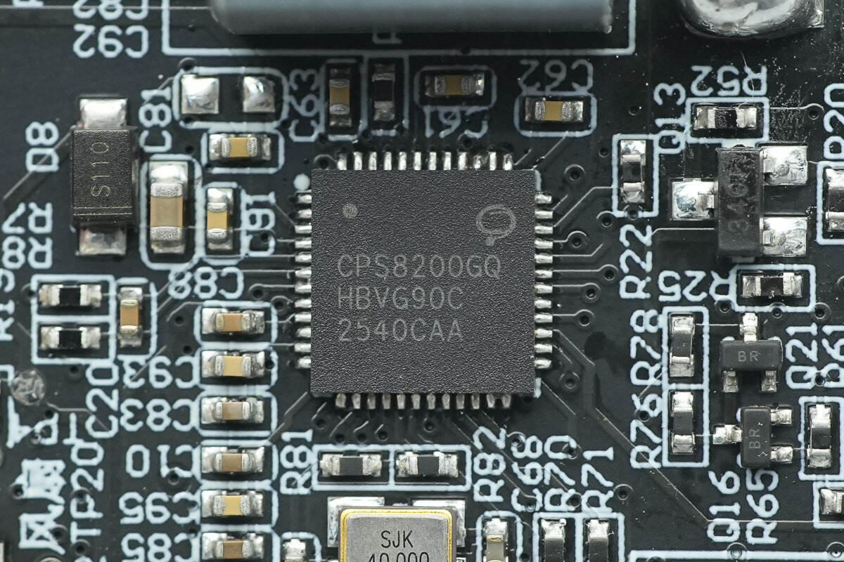
The wireless charging master control chip is from CPS, model CPS8200. It is a highly integrated wireless charging transmitter chip, featuring a 32-bit processor, with an embedded 64+2KB MTP, 32KB ROM, and 2KB SRAM. The MTP supports read/write protection and allows programming via CC and DPDN. It includes two I2C interfaces and two UART interfaces. The chip also integrates a switch-mode buck converter, linear voltage regulator, DC-DC controller, full-bridge driver, communication module, and multi-channel 12-bit ADC.
The CPS8200 supports fast charging protocols such as QC2.0/QC3.0/PD3.1/SCP/AFC. It integrates three pairs of half-bridge drivers, supporting both boost and buck conversion. It also supports fixed-frequency voltage regulation charging, and with the appropriate MOSFETs, it can form a complete Qi2 wireless charger product. The chip supports a 24V input voltage, with the power stage supporting up to 45V input voltage. It also features over-voltage, over-current, and over-temperature protection functions.
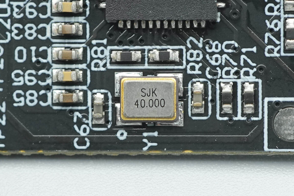
Close-up of the 40.000 MHz crystal oscillator.
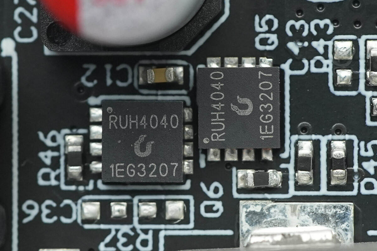
The synchronous boost MOSFETs are from Ruichips, model RUH4040. These are NMOS transistors with a voltage rating of 40V, an Rds(on) of 8mΩ, and are packaged in a PDFN3333 form factor.

Close-up of the 6.8μH boost inductor.
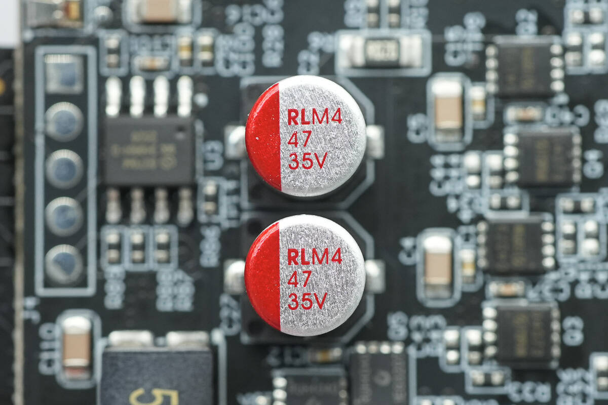
The two solid capacitors have a specification of 35V 47μF.
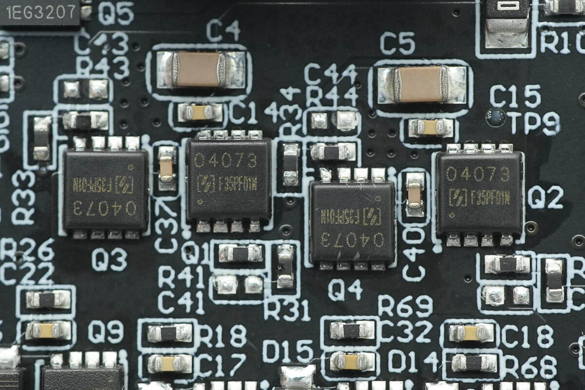
The four wireless charging power MOSFETs are from Oriental, marked with F35PF01N.
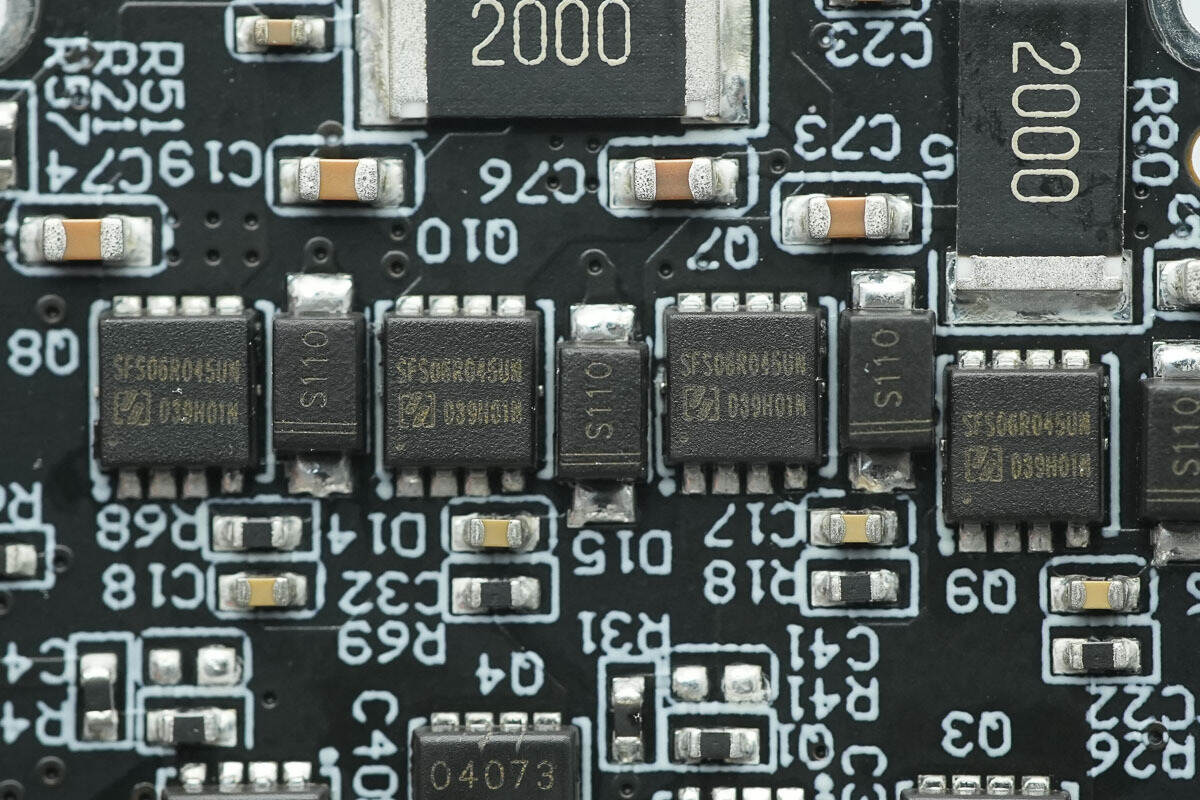
The MOSFETs used for switching the wireless charging coils are also from Oriental.
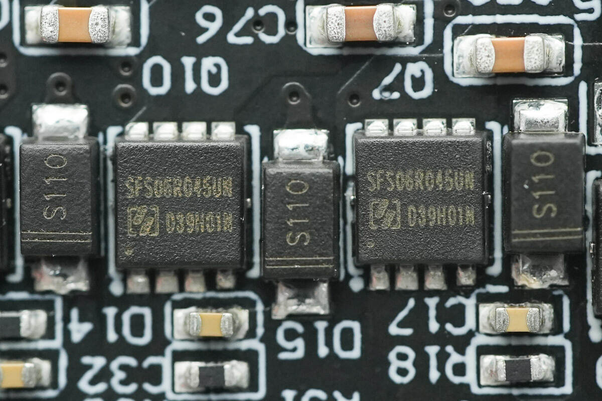
The four MOSFETs are all of the model SFS06R045UNF, NMOS type, with a voltage rating of 60V, a Rds(on) of 4.5mΩ, and are packaged in a PDFN 3.3*3.3 form factor.
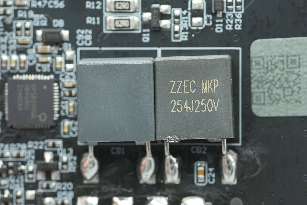
The two resonant capacitors are from the ZZEC series, specifically designed for wireless charging. Both have a specification of 0.25μF 250V.
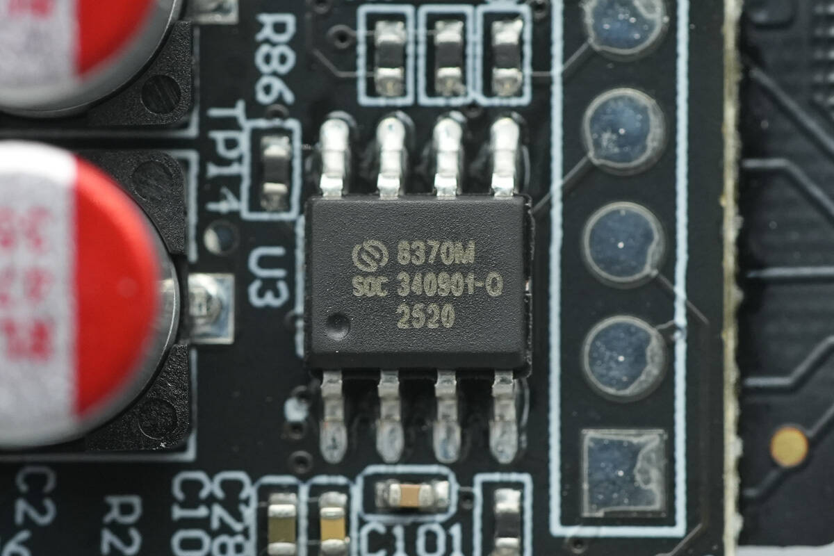
The MCU is from SinOne, model SC8370. It is an enhanced, ultra-high-speed 1T8051 core industrial-grade Flash microcontroller with integrated touch button functionality. The instruction set is fully compatible with the traditional 8051 product series. It is ideal for applications in various fields such as smart home appliances, smart homes, IoT, wireless communication, gaming consoles, and other industrial control and consumer applications.
Close-up of the touch contact points.
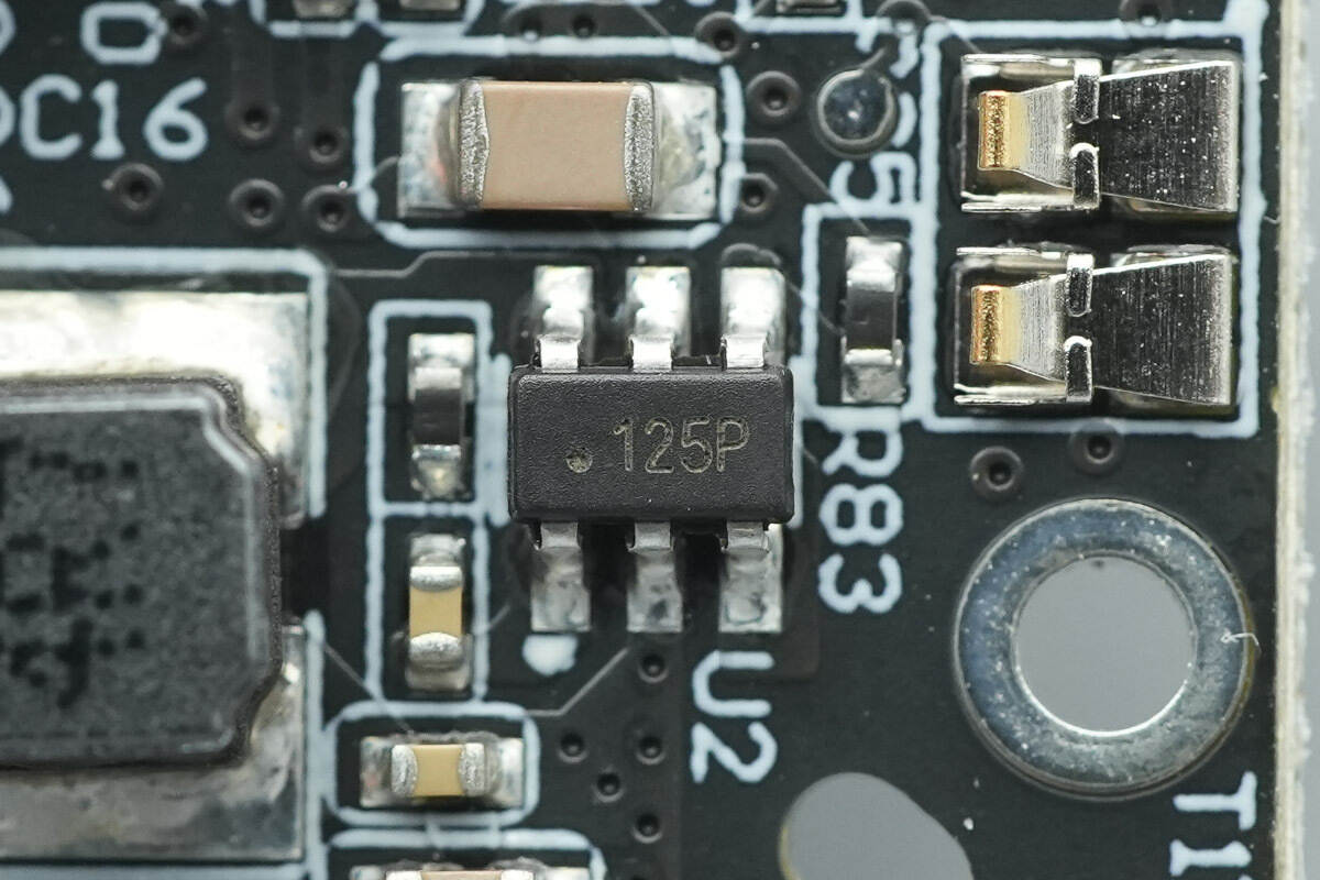
The synchronous buck converter used for powering the fan is marked with 125P and comes in a SOT23-6 package.
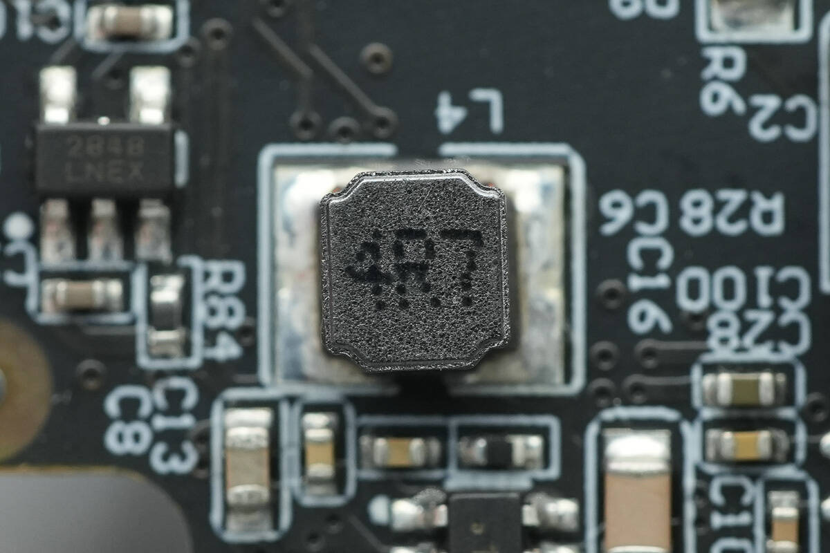
Close-up of the 4.7μH buck inductor.
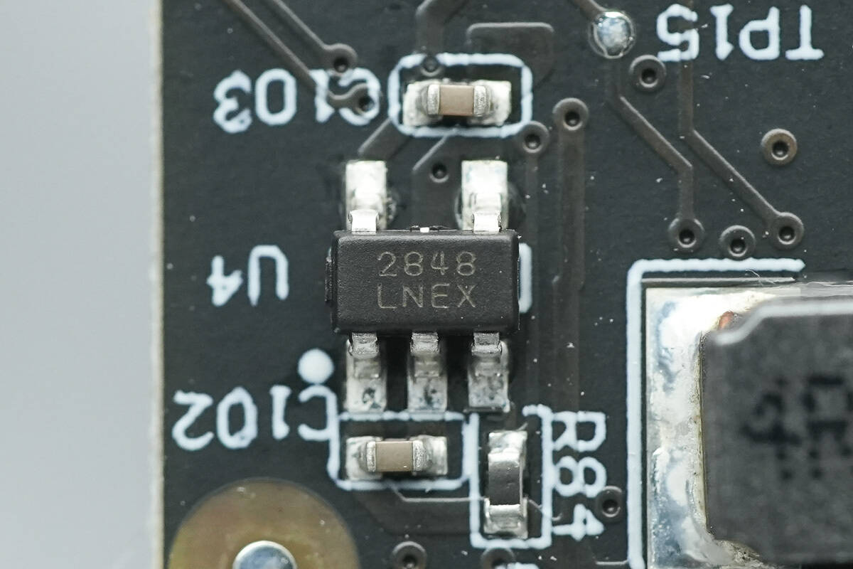
Close-up of the chip marked with 2848.
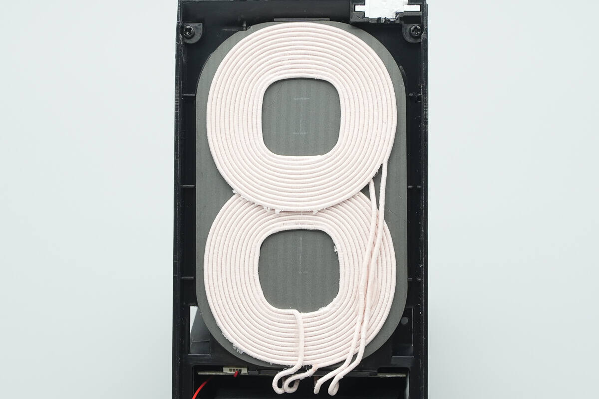
Close-up of the wireless charging dual coils.

Close-up of the LED light panel.
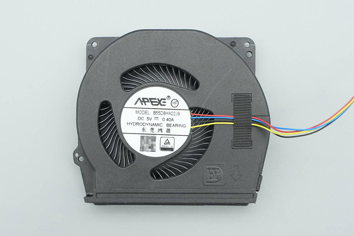
The fan is from Hongying, model B55D8HA22J9, with a rated input of 5V 0.4A.
Well, those are all components of the Meizu PANDAER 66W Vertical Air-cooled Wireless Charger.
Summary of ChargerLAB
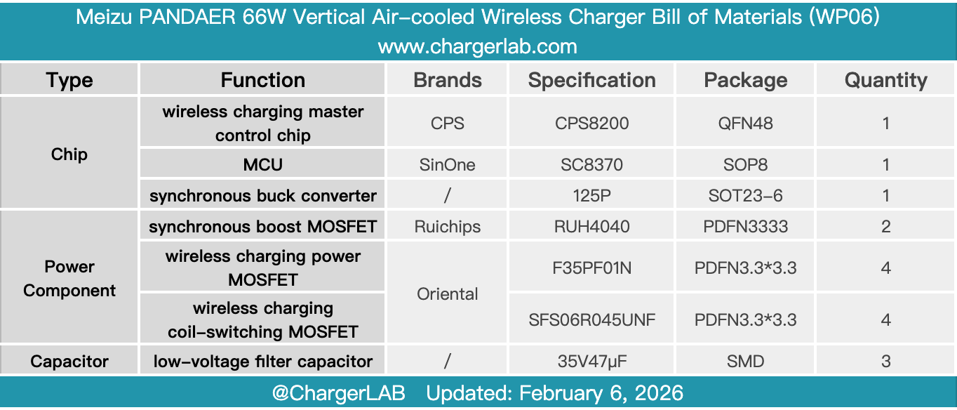
Here is the component list of the Meizu PANDAER 66W Vertical Air-cooled Wireless Charger for your convenience.
The built-in dual coils allow stable charging whether placed vertically or horizontally. The 65° tilt angle of the body makes it convenient for charging while using the device. The included height-adjustable pad ensures compatibility with more devices.
After taking it apart, we found that it is designed based on the CPS8200 wireless charging solution, paired with Ruichips MOSFETs for input boosting. The wireless charging power MOSFETs and coil switching MOSFETs are sourced from Oriental. It features an internal cooling fan, and together with the heat dissipation outlets, forms a three-dimensional cooling system. The USB-C interface area is equipped with a thermal copper sheet. These thorough cooling measures ensure an optimal experience during high-power wireless charging.
Related Articles:
1. Teardown of VERTIV 3500W SiC Rectifier Module (R48-3500e3)
2. Teardown of EcoFlow 240W USB4 Fast Charging Braided Cable
3. Teardown of VERYSUN 100W GaN Charger (X100Pro)