Introduction
We obtained a multifunctional vehicle emergency jump starter from Maxcellent. It features an aluminum-alloy housing and provides engine start assistance, tire inflation, both blowing and suction functions, and built-in lighting. The unit includes USB-C and USB-A ports and is powered by four series-connected high-rate LiFePO₄ cells with a total capacity of 60 Ah, suitable for starting vehicles equipped with 12 V lead-acid batteries. It can also be paired with an inverter to deliver up to 500 W of output power. Next, let’s take a closer look at its internal components and design.
Product Appearance
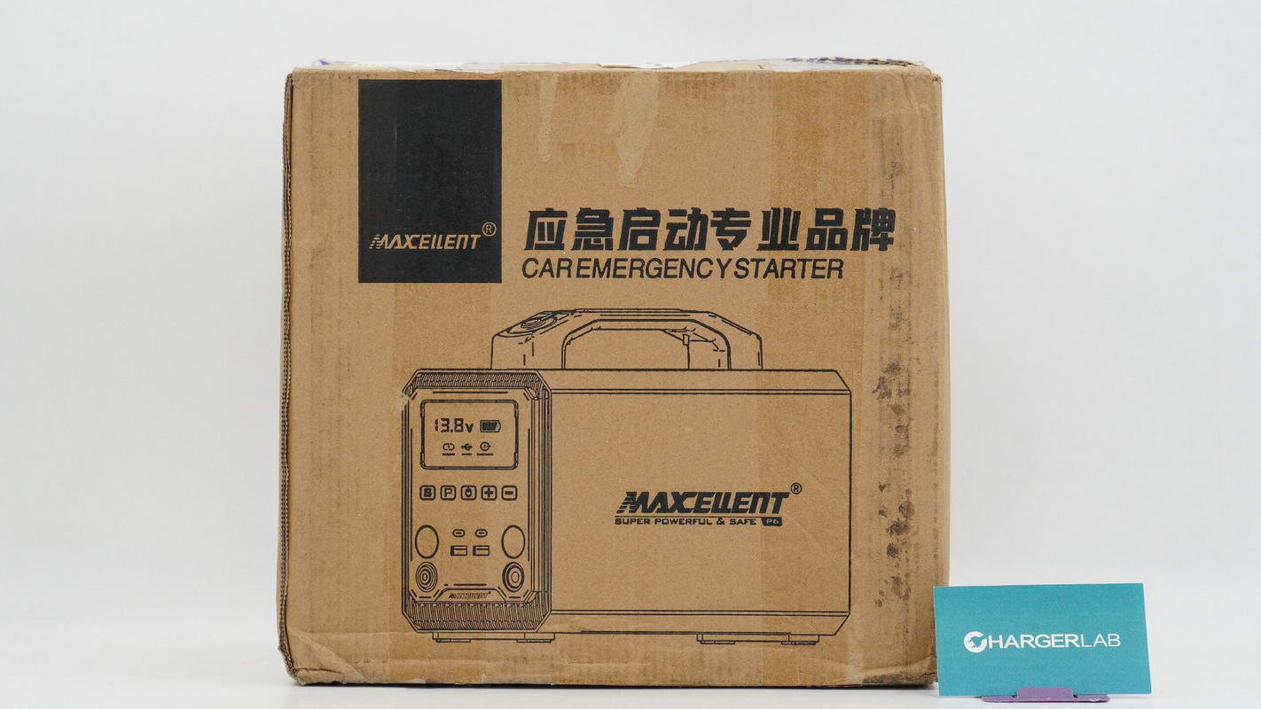
It comes packaged in a Kraft paper box.

The accessories are stored inside a carrying pouch.
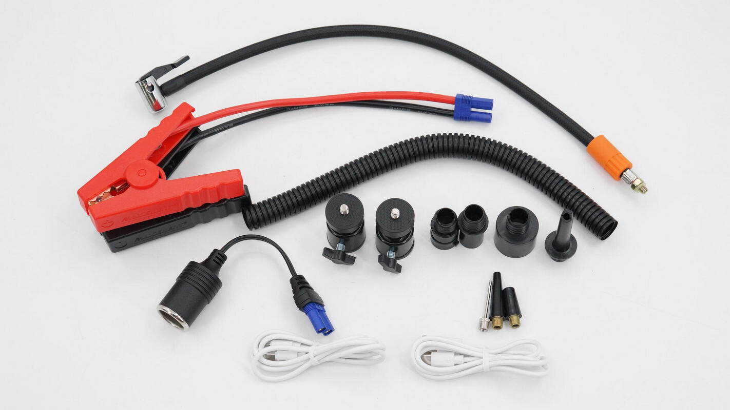
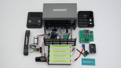
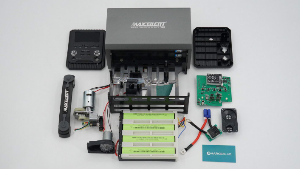
An overview of the included accessories.

This is the hose used for inflating tires.
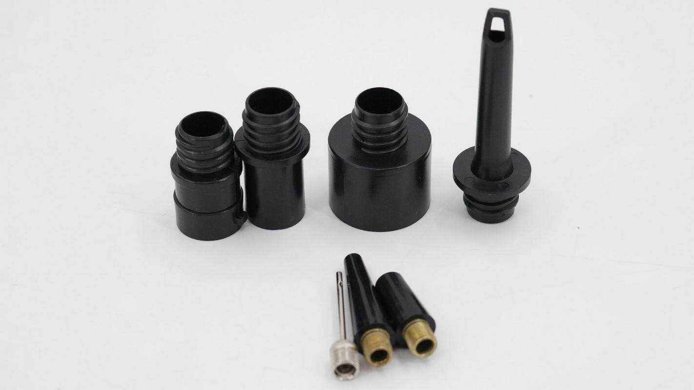
A close-up of the various nozzles.
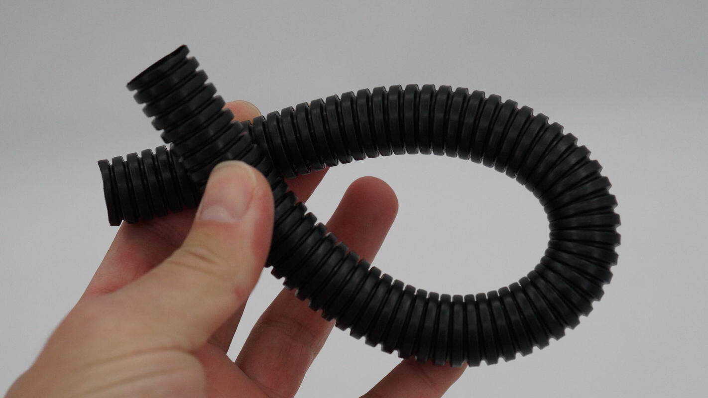
A close-up of the hose.

The cable clamps feature reinforced jaws to improve their current-carrying capability.
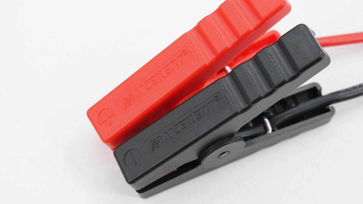
The exterior of the cable clamps is marked with "MAXCELLENT."
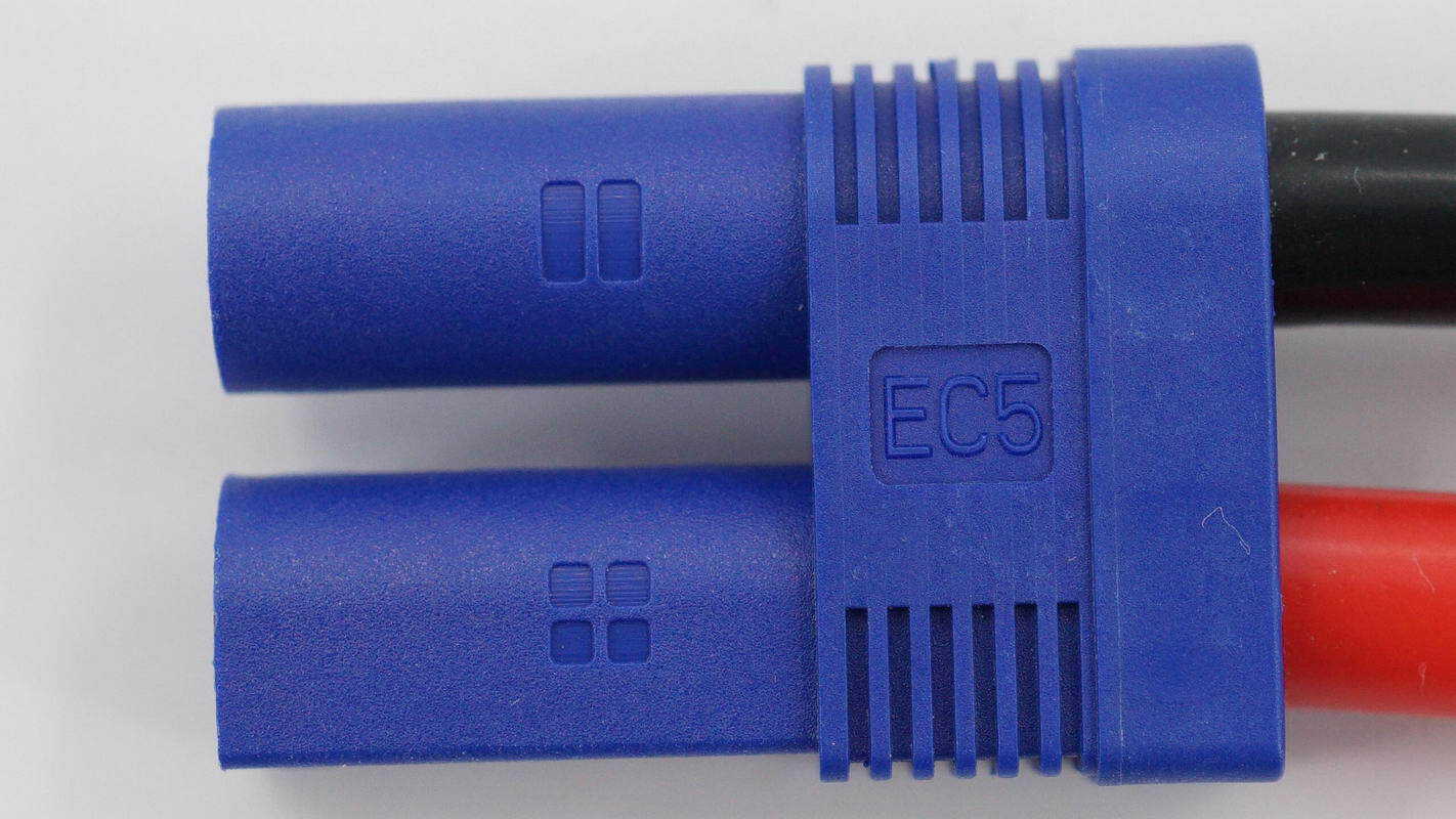
The cable clamps are connected to the jump starter via an EC5 connector.

It comes with a USB-C charging cable.

The other cable is a USB-A to USB-C charging cable.
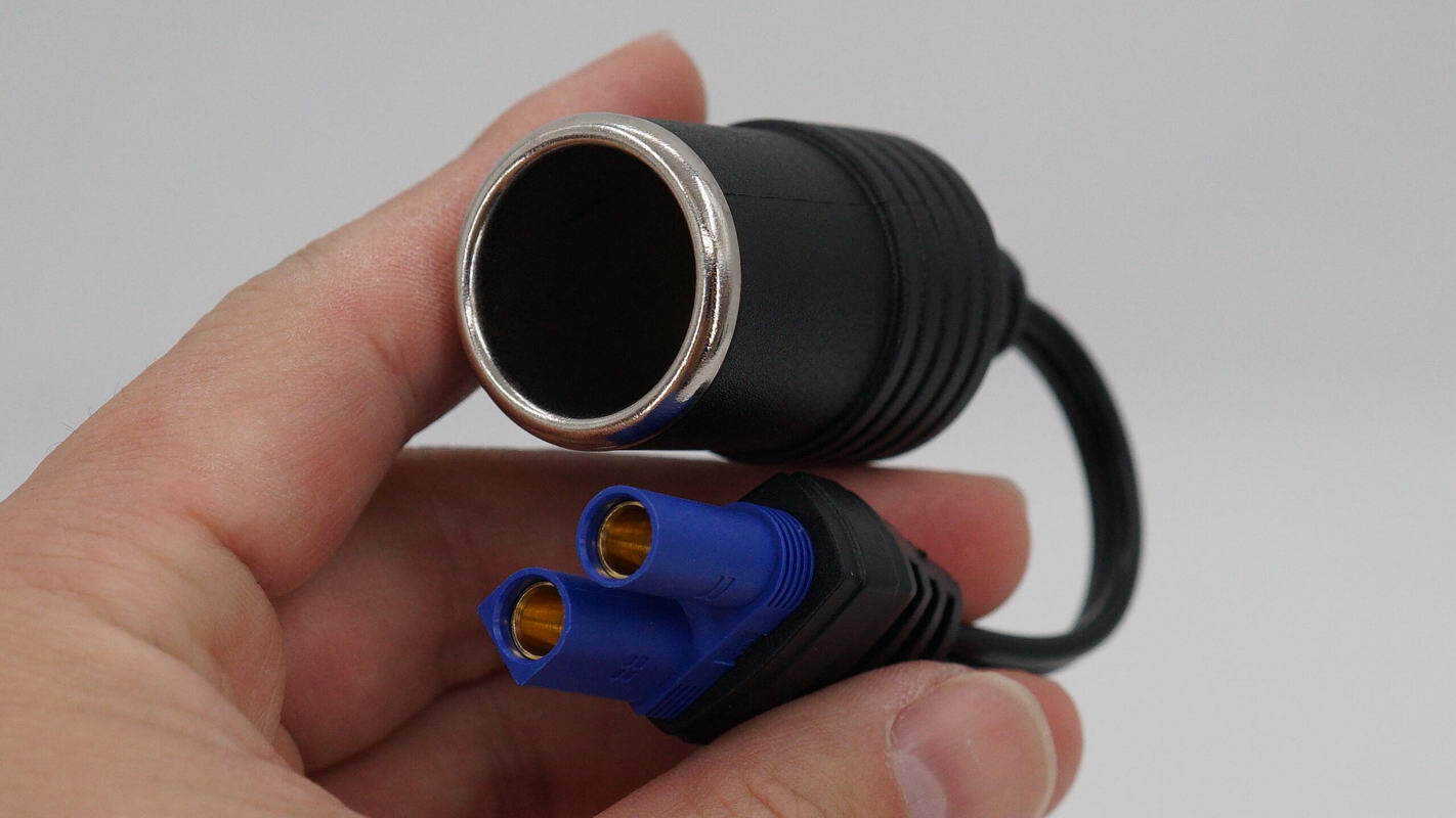
A close-up of the adapter for connecting to a car charger.
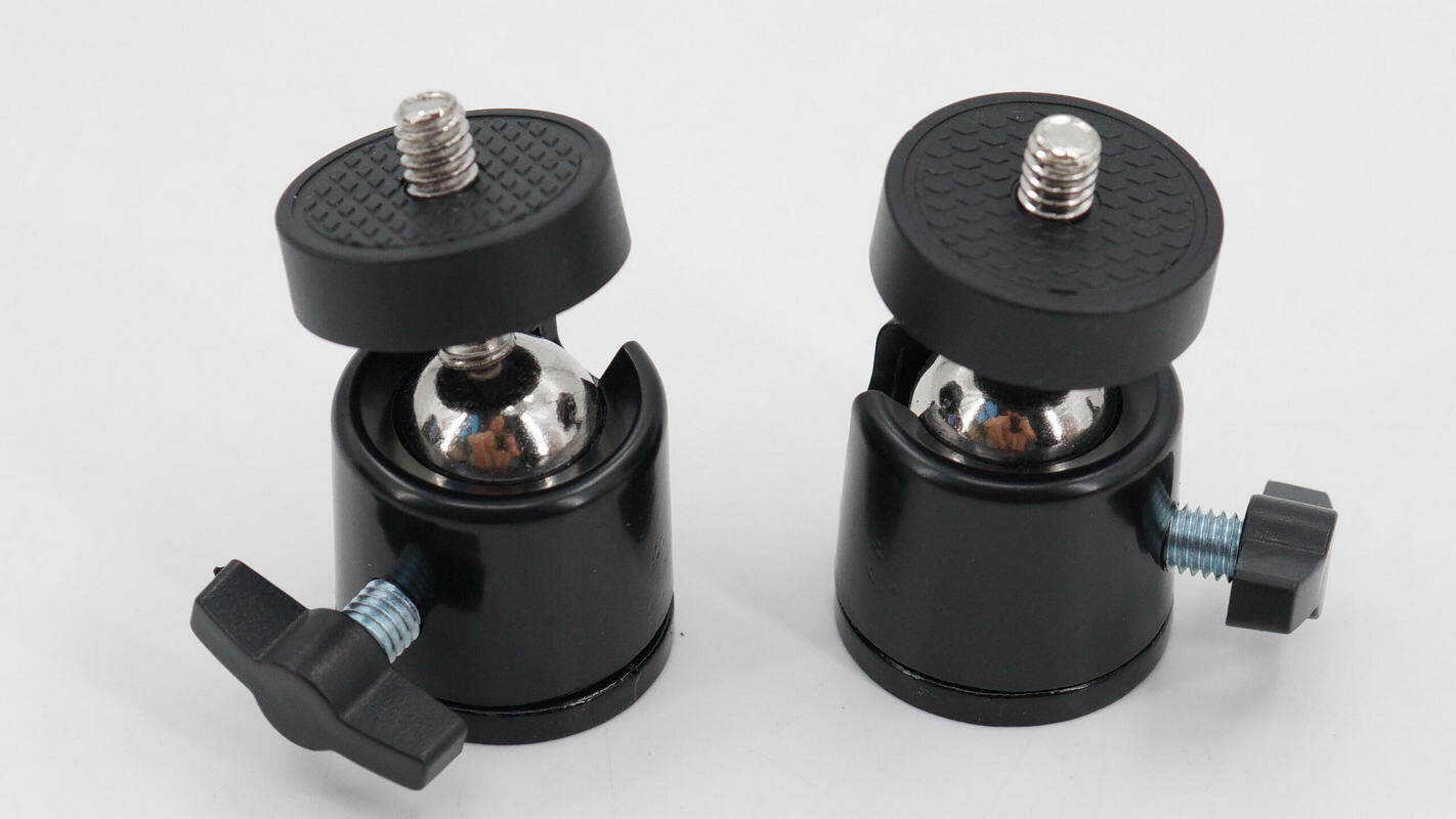
The included gimbal mount can be used to attach additional accessories.
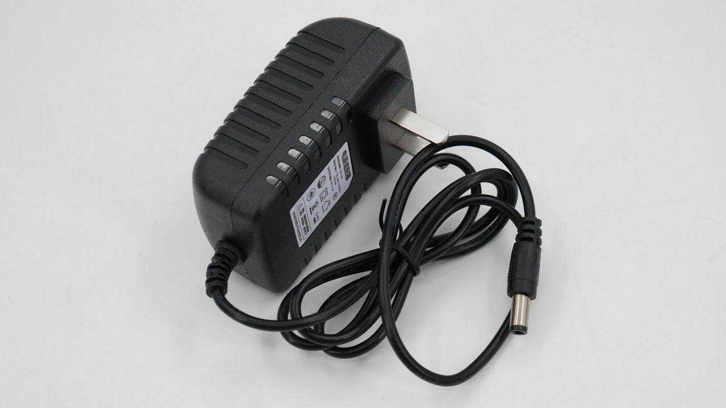
Close-up of the power adapter.

The adapter supports an input voltage of 100–240 V and provides an output of 19 V 2 A.

The adapter uses a DC plug.
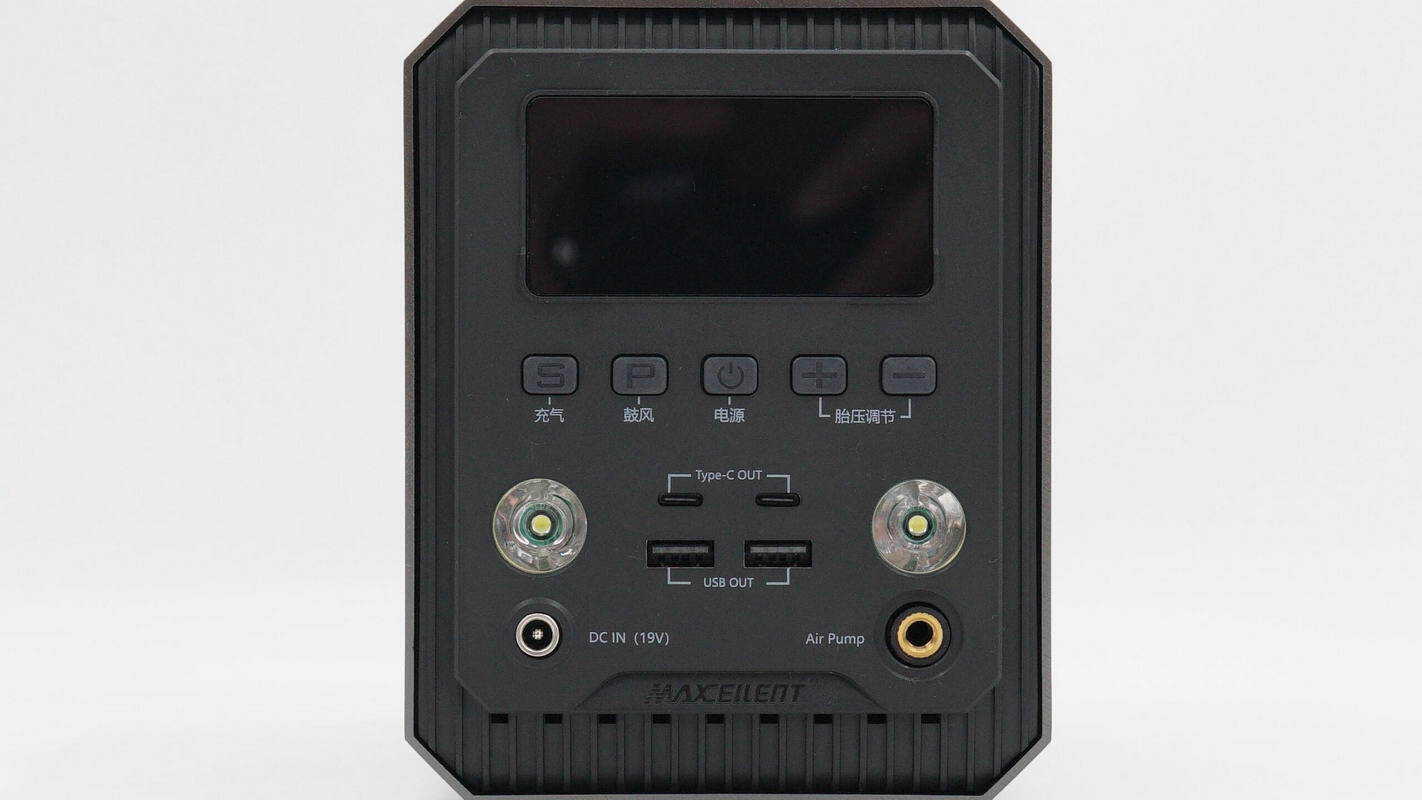
The front panel of the jump starter features a screen, buttons, LED lights, a DC port, an air inflation port, and USB-C and USB-A ports.
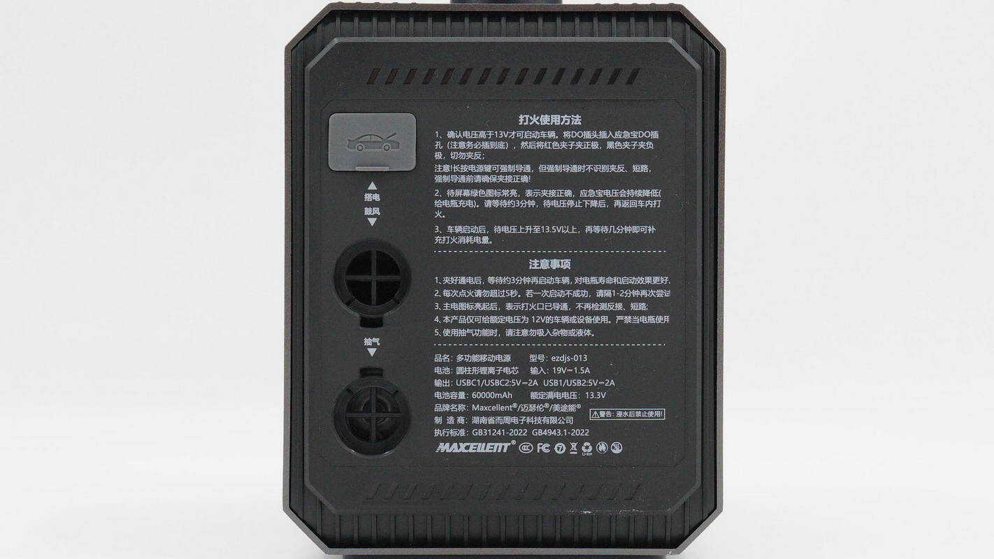
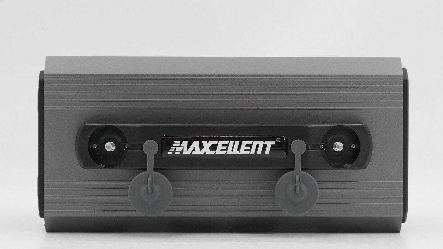
The rear panel includes jump-start terminals as well as air blow and suction ports. The right side is printed with usage instructions, safety precautions, and technical specifications.
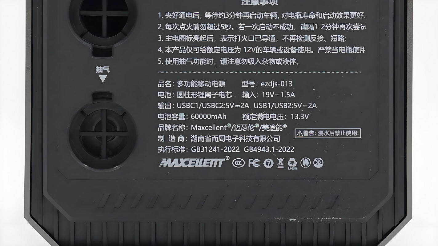
Model: ezdjs-013
Battery: Cylindrical lithium-ion cells
Input: 19 V ⎓ 1.5 A
Output: USB-C1 / USB-C2: 5 V ⎓ 2 A, USB1 / USB2: 5 V ⎓ 2 A
Battery Capacity: 60,000 mAh
Rated Full-Charge Voltage: 13.3 V
The product has passed CCC certification.
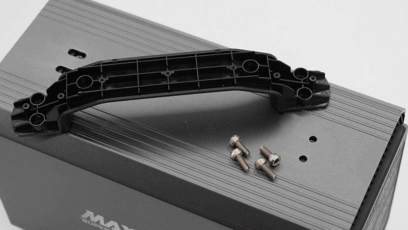
A carrying handle is located on the top.
Screws are located beneath the covers on both sides of the handle.
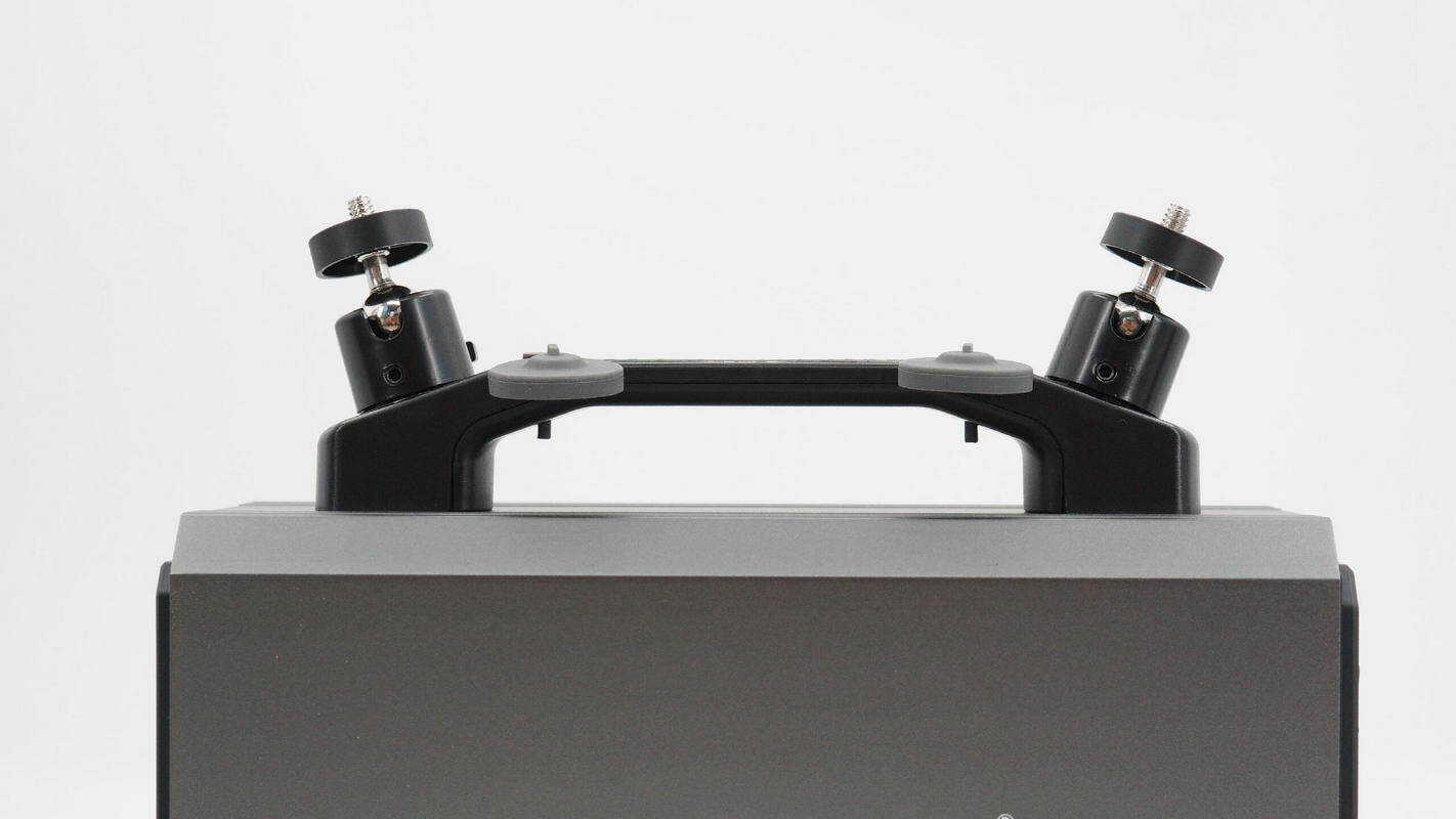
The gimbal mount is installed onto the screws located on both sides of the handle.
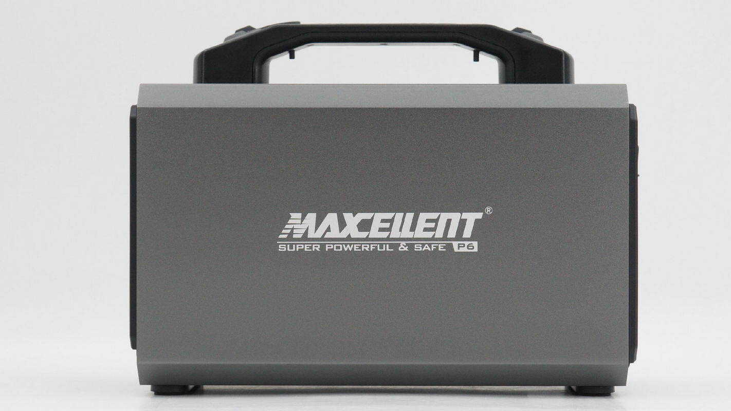
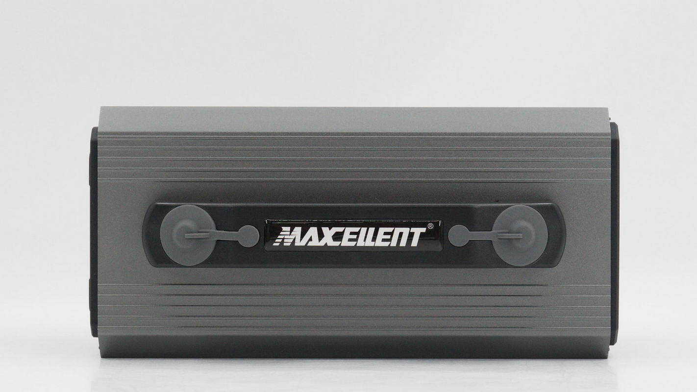
This side is marked with "MAXCELLENT."

The other side is marked with "Multifunction Vehicle Emergency System."
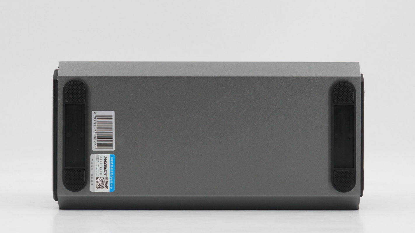
The bottom is equipped with anti-slip feet.

The length is about 253 mm (9.96 inches).

The height is about 185 mm (7.28 inches).

The width is about 119 mm (4.69 inches).

The weight is about 2.8 kg (6.17 pounds).
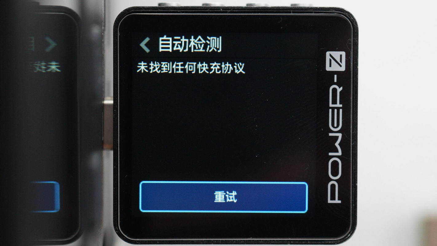
The USB-C ports do not support any fast-charging protocols.
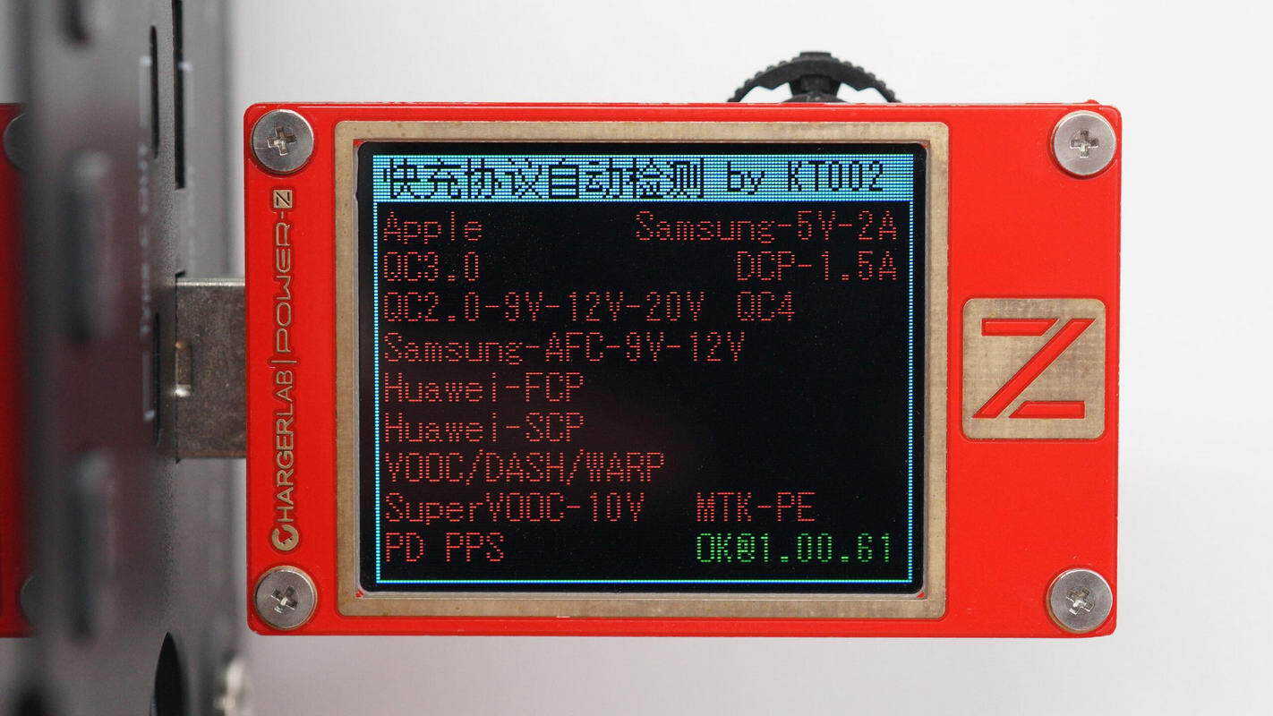
The USB-A ports do not support any fast-charging protocols either.
Teardown
Next, let's take it apart to see its internal components and structure.
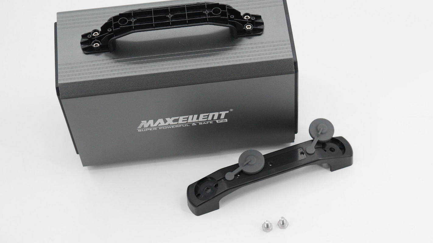
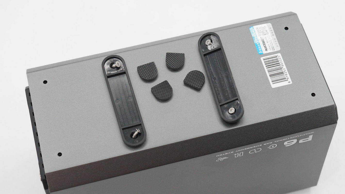
Unscrew the screws on both sides of the handle and remove the handle.
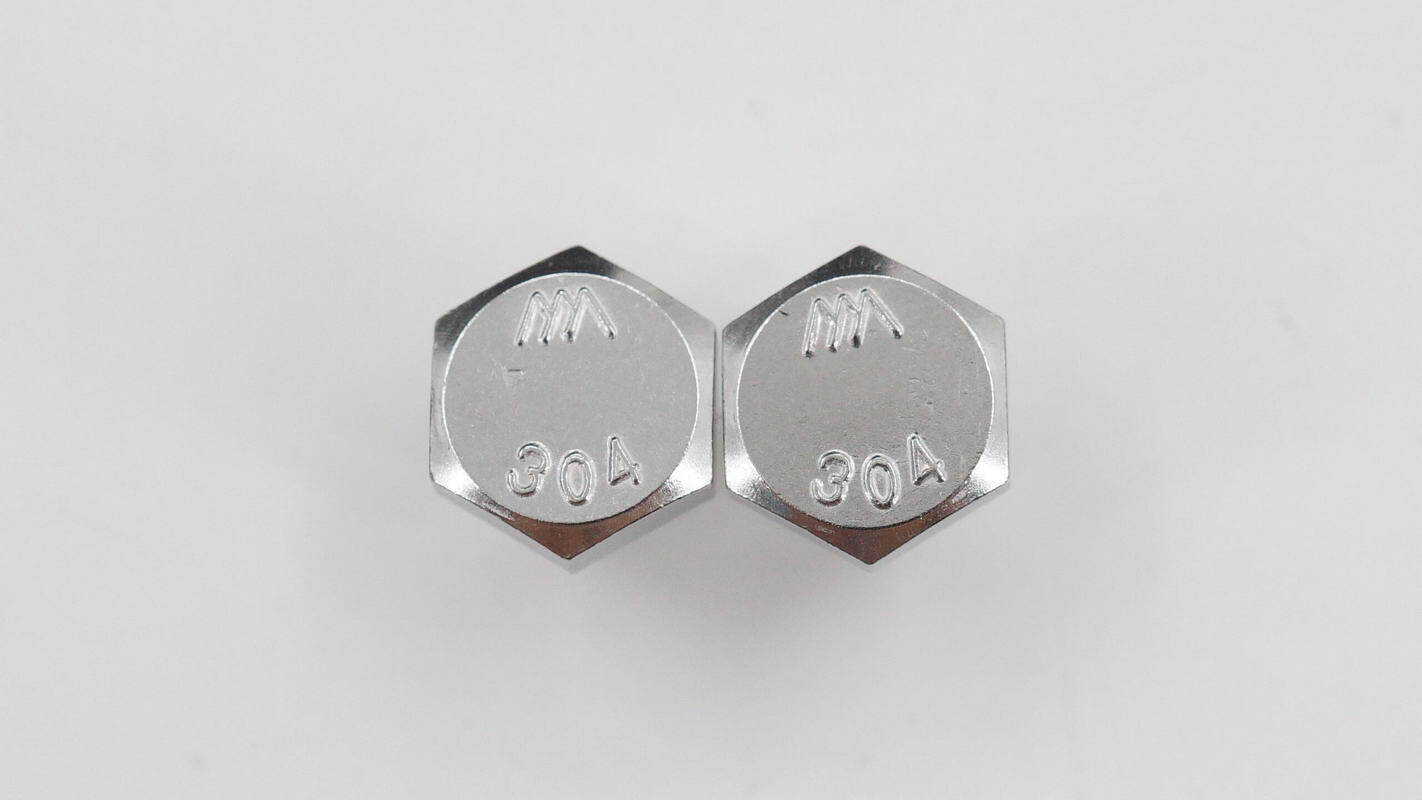
Inside the handle, there are bolts for securing the gimbal mount.
Continue unscrewing the screws to remove the handle.
Remove the anti-slip feet at the bottom and unscrew the mounting screws.
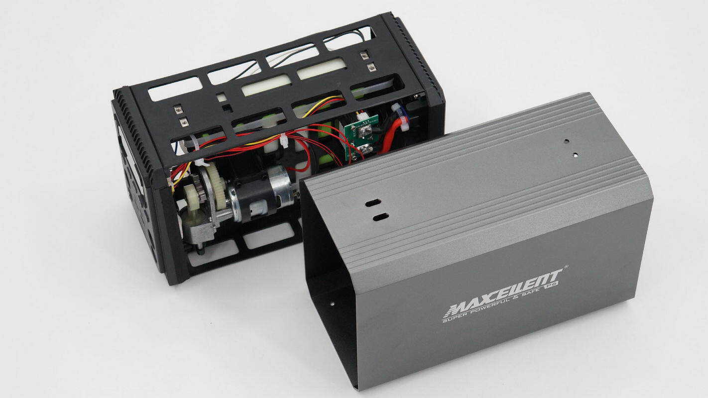
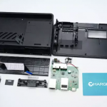
Remove the internal module from the housing.

The thickness of the aluminum-alloy housing is about 1.87 mm (0.074 inches).

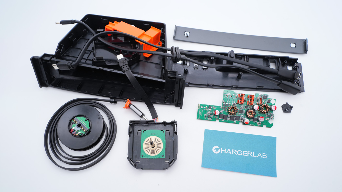
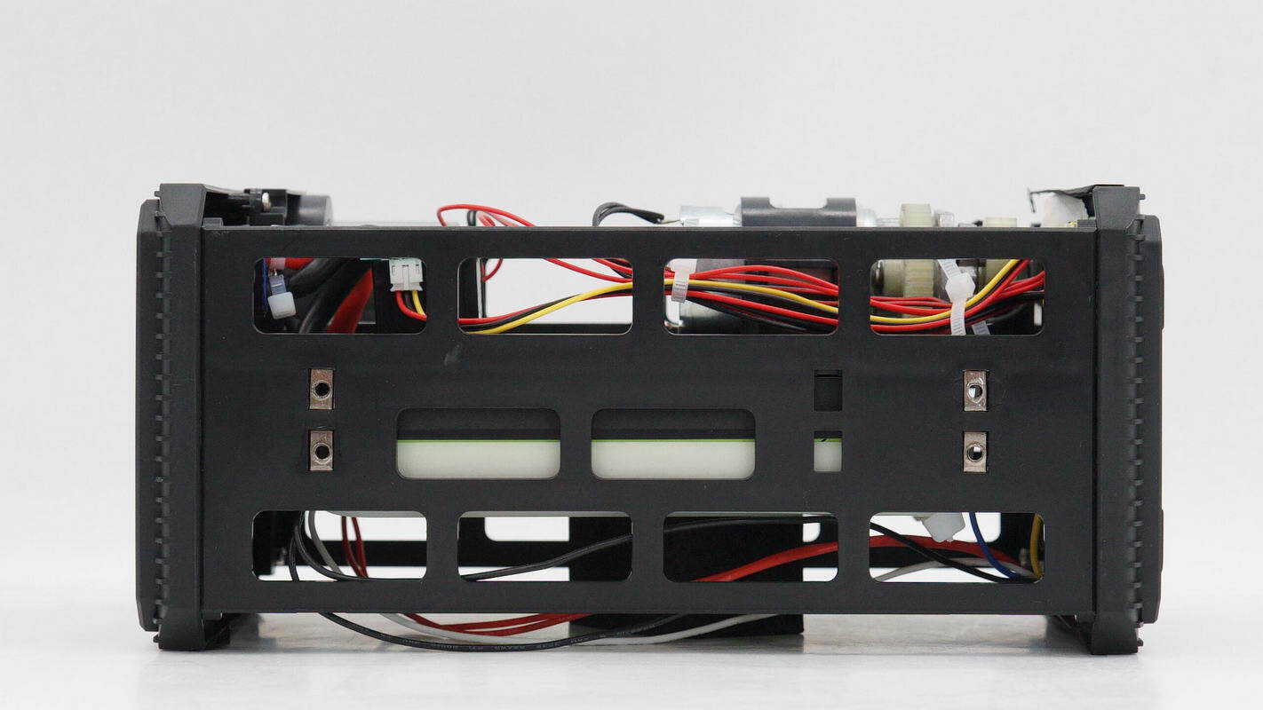
The side of the internal module houses the air pump and fan, as well as the relay controlling the jump-start output.
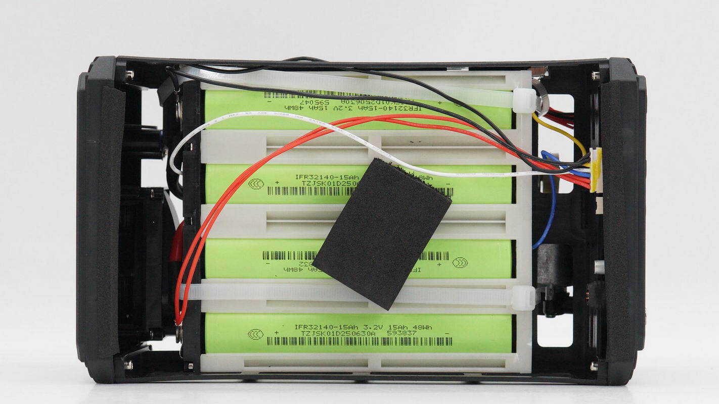
The other side contains the battery pack, secured with zip ties and cushioned with foam padding.
The plastic bracket on top features screw holes for the handle.
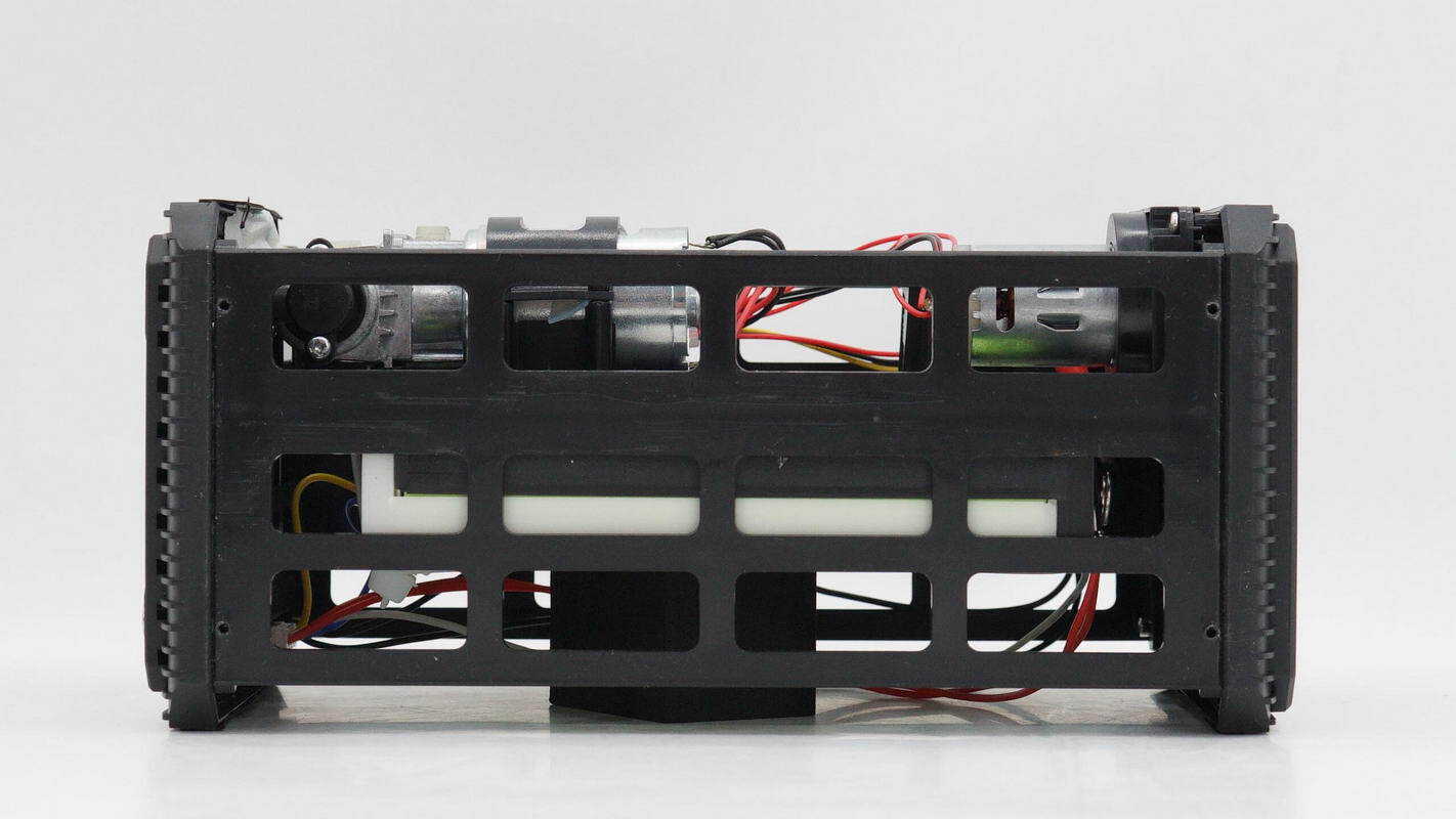
The bottom has screw holes for the anti-slip feet.
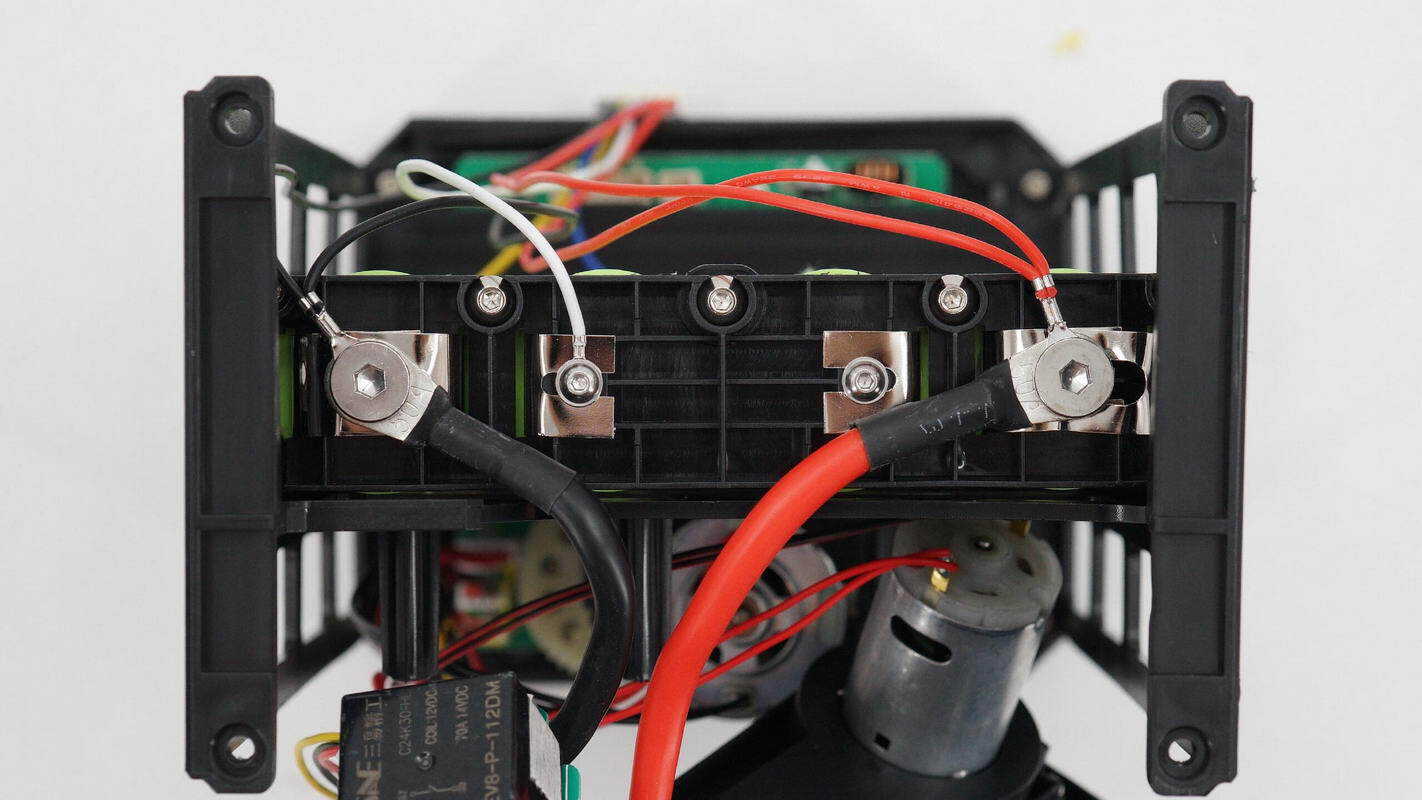
Remove the side panel. The battery pack is connected via screw terminals.

The battery pack is connected to the EC5 connector via wires, with the output controlled by a relay.

Remove the side end caps and the battery pack.
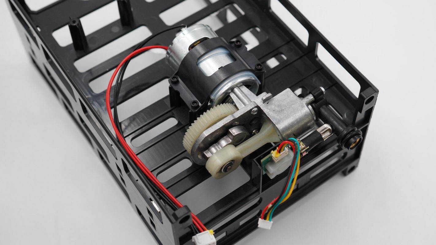
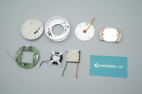
The air pump for tire inflation is mounted inside the bracket and is equipped with a pressure sensor.
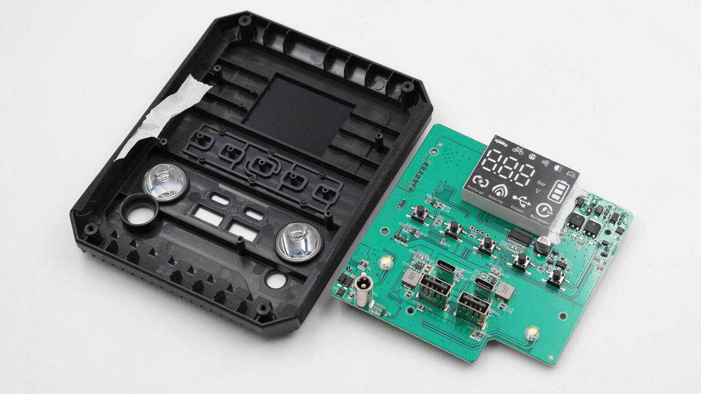
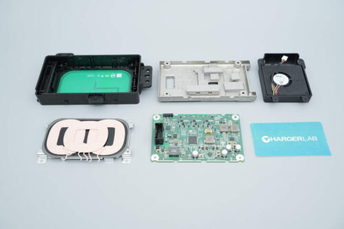
The PCBA module is mounted inside the panel.

A close-up of the LED lamp cup.

The front of the PCBA module features an LED display, MOSFETs, a driver, buttons, and the buck circuit.
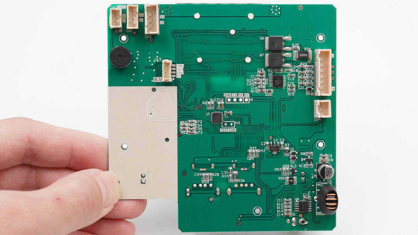
The back of the PCBA module houses connectors, a buzzer, a pressure sensor, a battery protection chip, battery protection MOSFETs, an MCU, a battery charging IC, a buck inductor, and filter capacitors.

The battery protection chip is an iCM CM1041, specifically designed for 4-series LiFePO₄/Li-ion batteries. It integrates high-precision voltage and current detection circuits, monitoring each cell’s voltage, charge/discharge current, and temperature to provide protection against overcharge, over-discharge, overcurrent during discharge, short circuits, overcurrent during charging, and temperature anomalies.
The CM1041 supports three-level overcurrent protection during discharge, battery disconnection protection, and NTC thermistor disconnection protection. It features low operating current and low sleep current, making it suitable for applications such as power tools, robotic vacuum cleaners, and UPS backup power supplies. The chip comes in a TSSOP16 package.
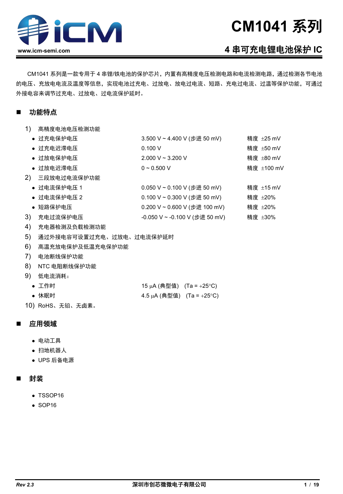
Here is the information about iCM CM1041.

The battery protection MOSFETs are iCM CMT30H10U, NMOS type, rated for 30 V with an on-resistance of 3.2 mΩ. They are suitable for load switch, UPS, and battery protection applications, and come in a TO-252 package.
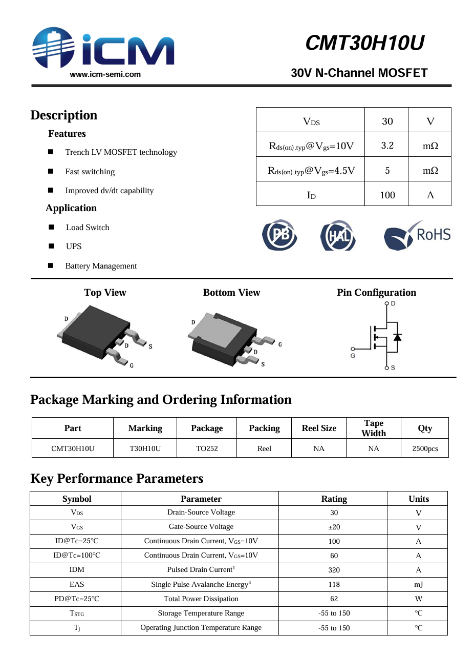
Here is the information about iCM CMT30H10U.
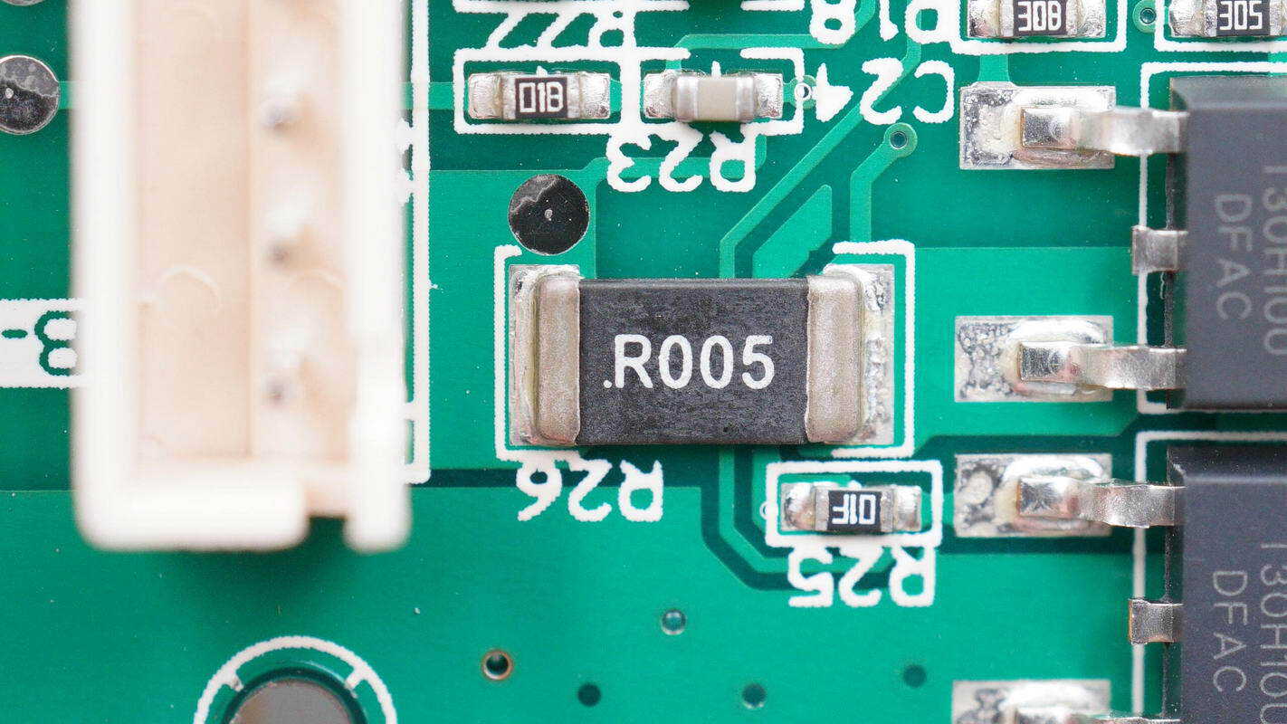
The 5 mΩ resistor is used to monitor the charge and discharge current of the battery pack.
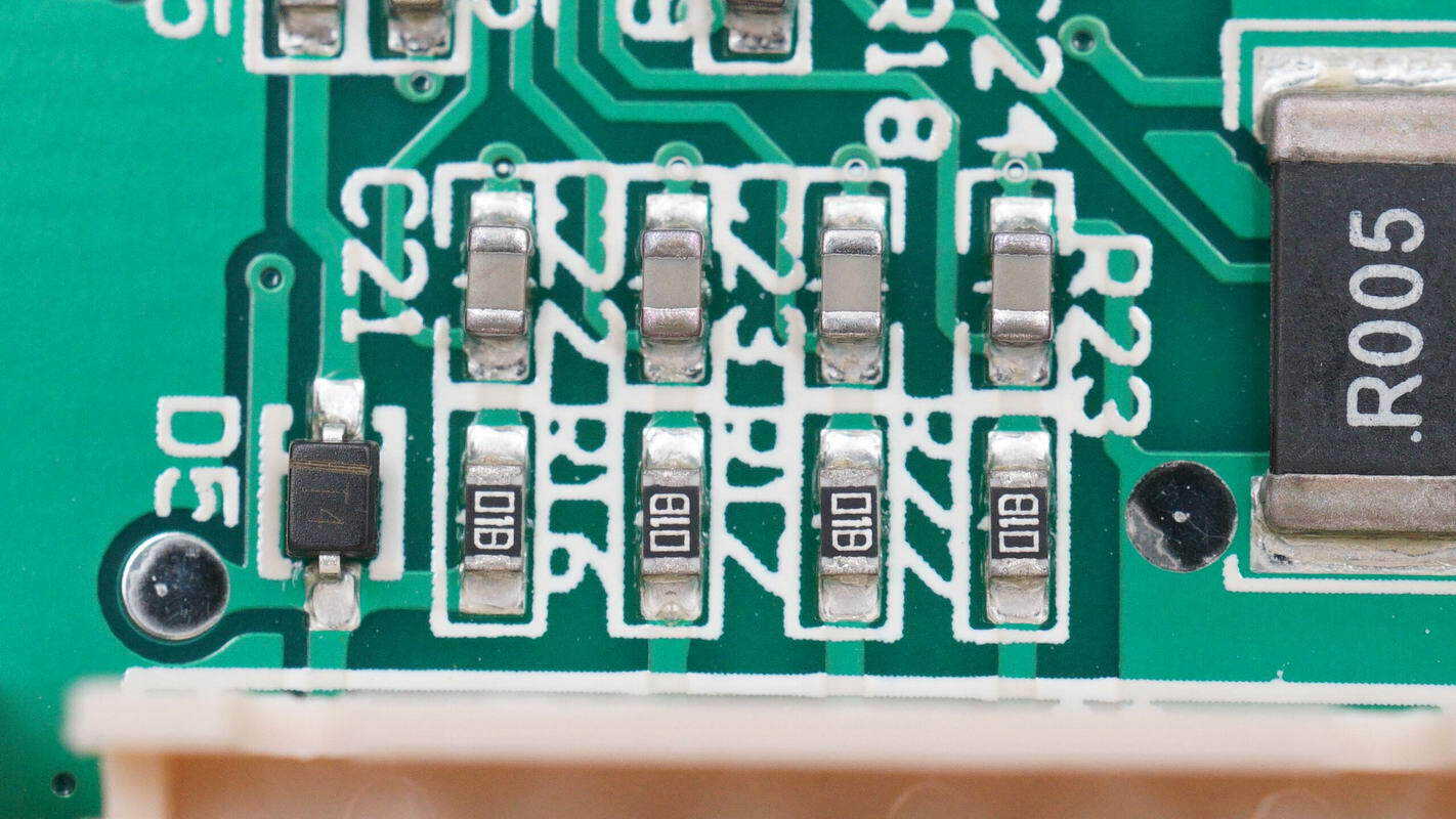
A close-up of the resistors and filter capacitors used for individual cell voltage sensing.
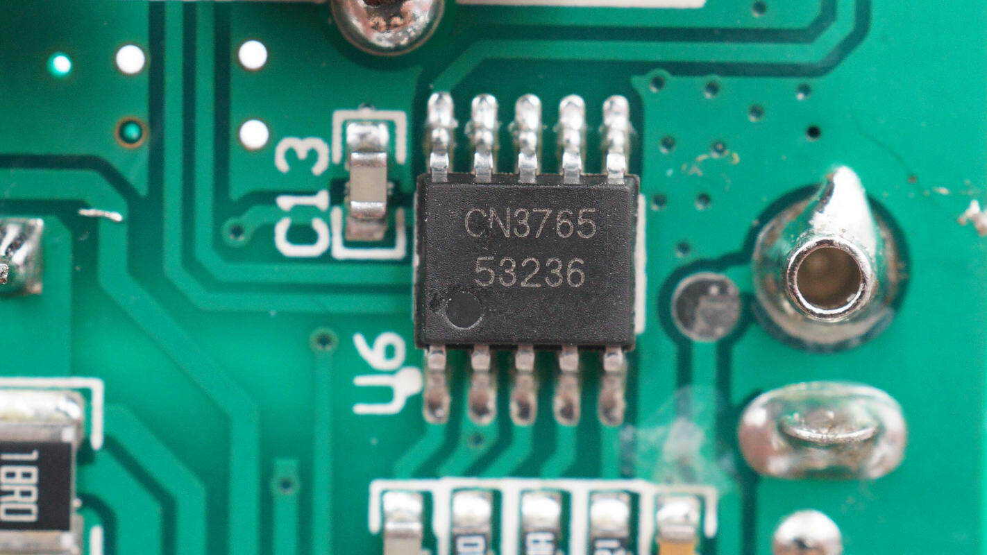
The battery charging IC is a CONSONANCE CN3765, a switching buck charger designed for multi-cell lithium batteries. It supports an input voltage range of 6.6–30 V, operates at a switching frequency of 310 kHz, and can deliver an output current of up to 4 A. The IC uses external MOSFETs and diodes, with both charging voltage and current set via external resistors. It supports automatic recharge and provides charge and charge-completion indicators. The chip comes in an SSOP10 package.

The charging MOSFET is an iCM CMT30P30K, a PMOS rated for –30 V with an on-resistance of 12 mΩ. It is suitable for load switch and fast-charging applications and comes in a 3×3 mm PDFN package.
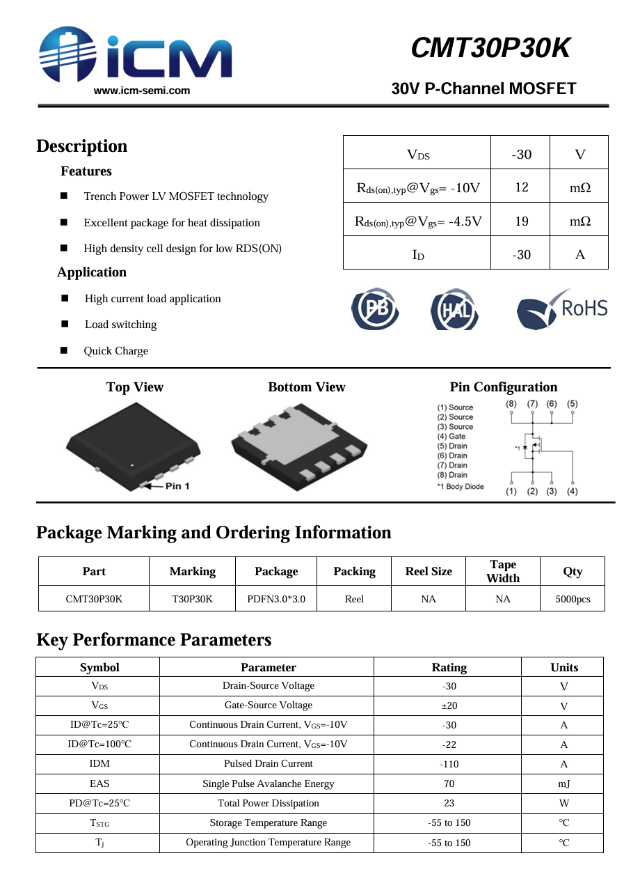
Here is the information about iCM CMT30P30K.
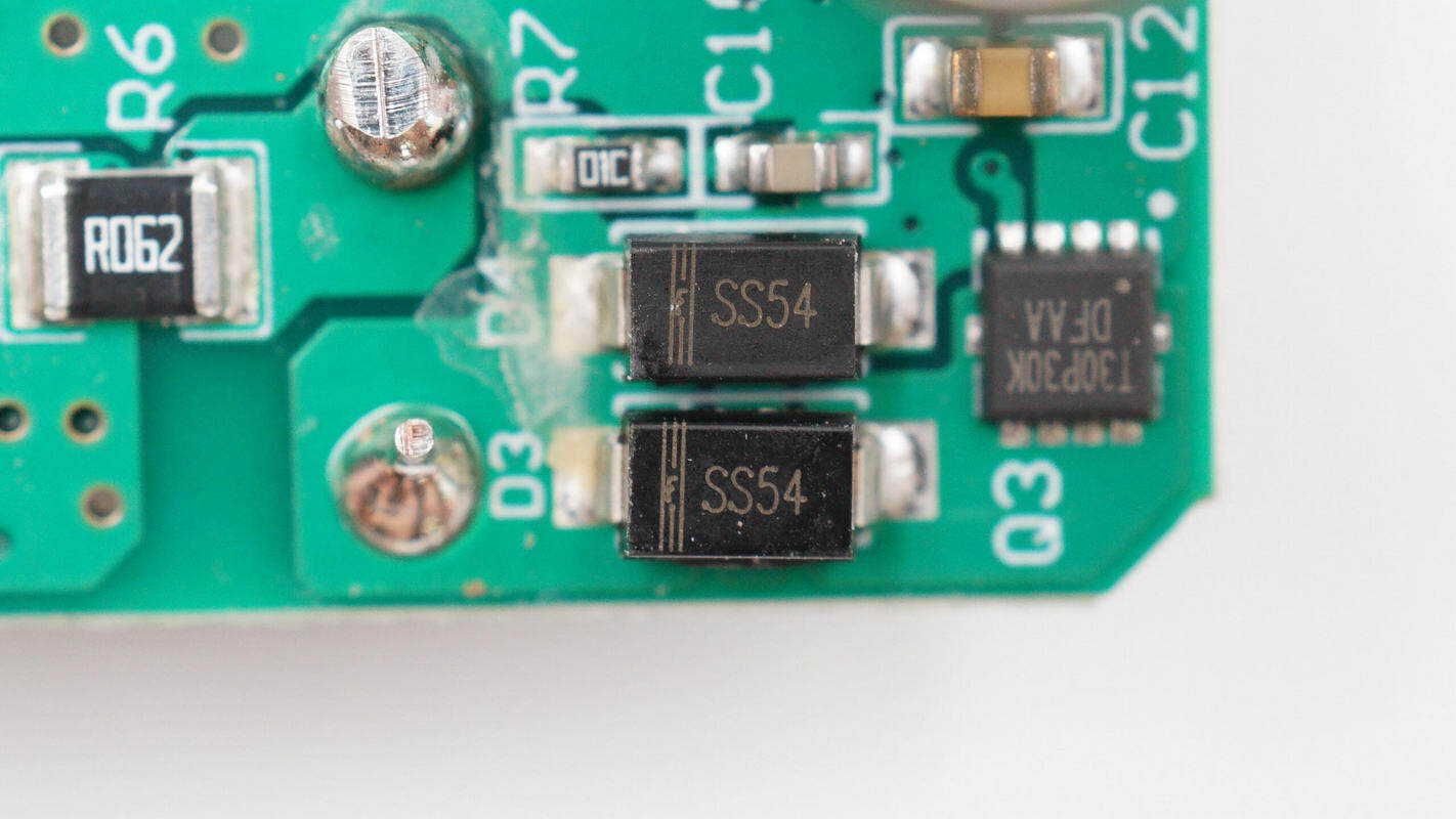
Two SS54 Schottky diodes are used to prevent reverse current and continuous current flow from the battery.
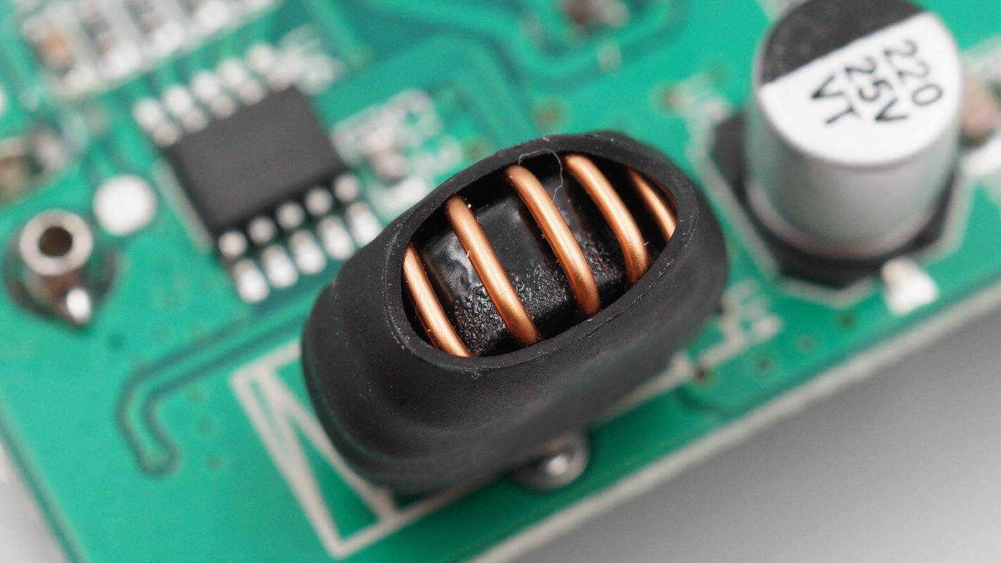
The inductor is wound with enameled wire and insulated with a heat-shrink tube.
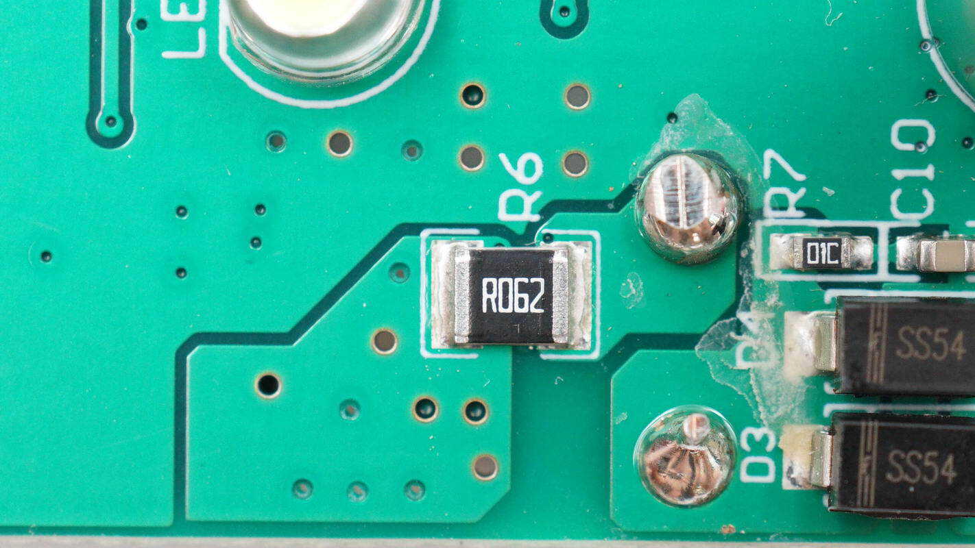
A 62 mΩ resistor is used to sense the charging current.

The output filter capacitor is rated at 220 μF, 25 V.
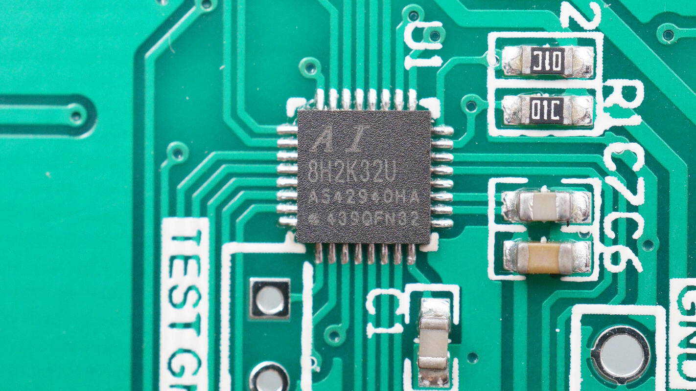
The MCU is an STCAI AI8H2K32U, supporting an operating voltage of 1.9–5.5 V. It features 32 KB of flash memory, 256 B of RAM, and 2.25 KB of SRAM. The MCU includes timers, UART, and I²C interfaces, as well as an integrated high-speed ADC and DAC. It comes in a QFN32 package.

The display driver chip is a TM TM1640, supporting an 8-segment × 16-digit display mode and 8-level brightness adjustment. It connects via a two-wire serial interface and comes in an SSOP28 package.
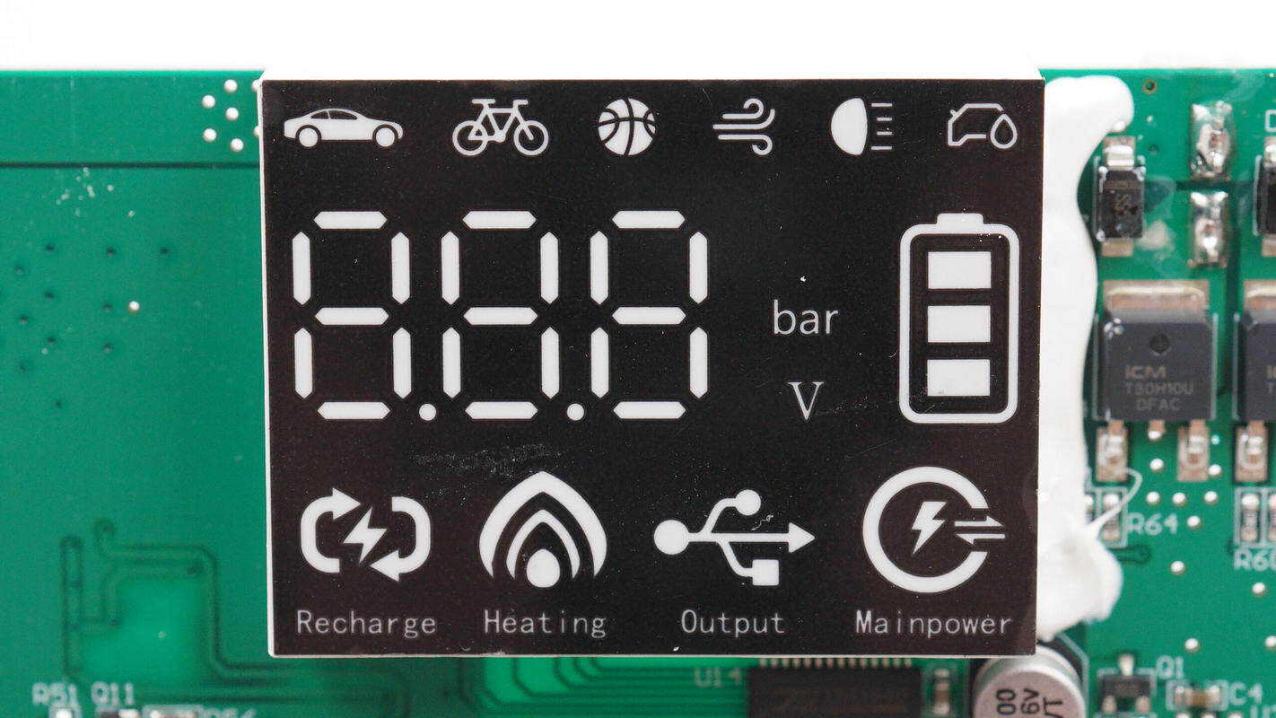
The LED display can show the inflation mode, air pressure, battery voltage, and battery level.
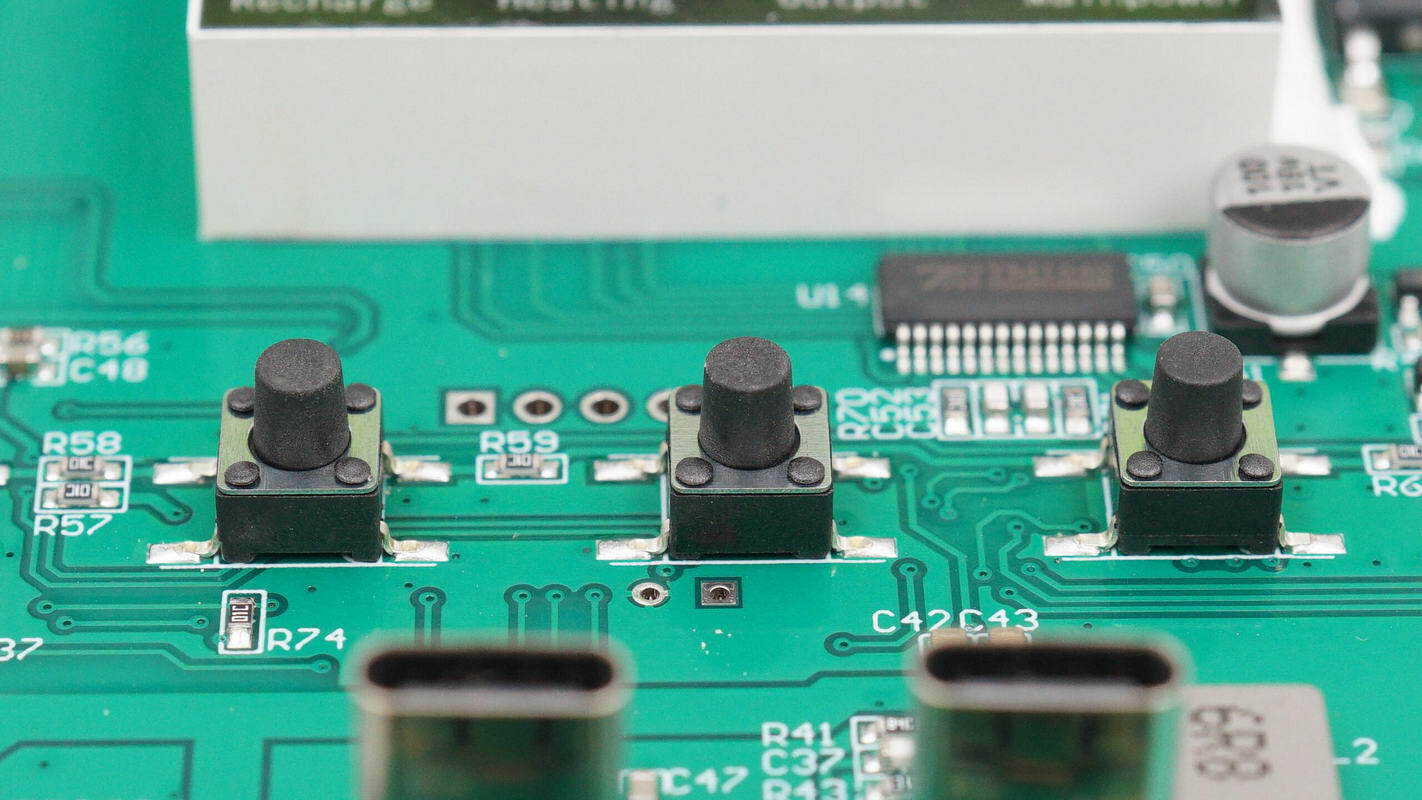
The buttons are surface-mounted.
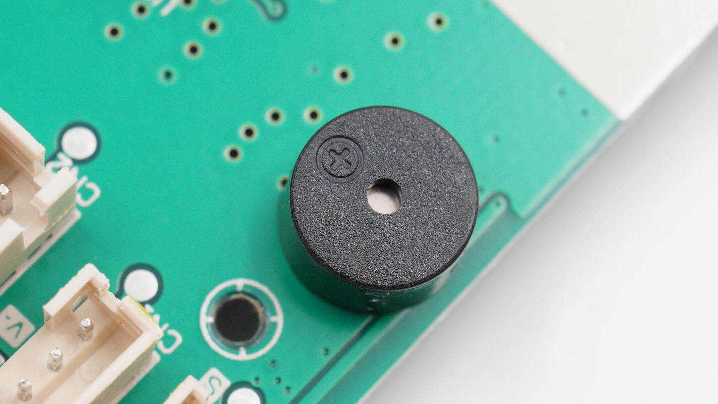
The buzzer is used for function notifications.
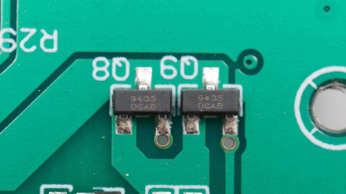
The power-control MOSFETs are iCM CMT9435R, PMOS, rated for –30 V with an on-resistance of 50 mΩ. Two units are connected in parallel in a SOT23 package, used for supply control in the buck circuit.
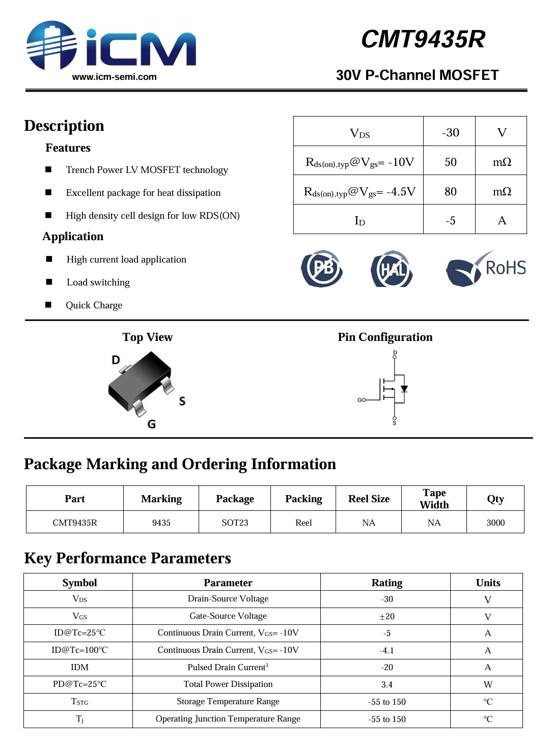
Here is the information about iCM CMT9435R.
There are two buck circuits, dedicated to providing 5 V output for the USB-C and USB-A ports, respectively.
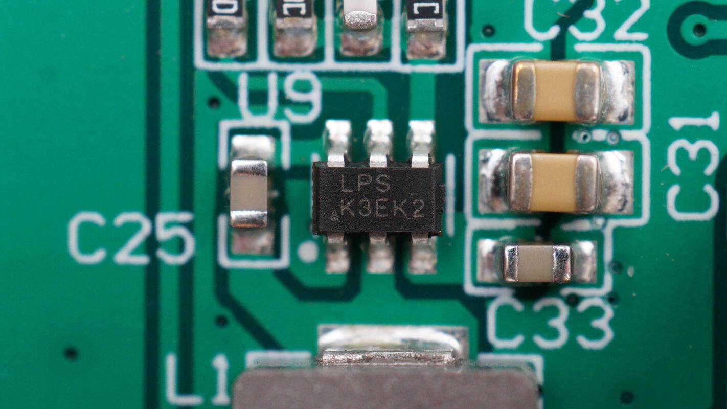
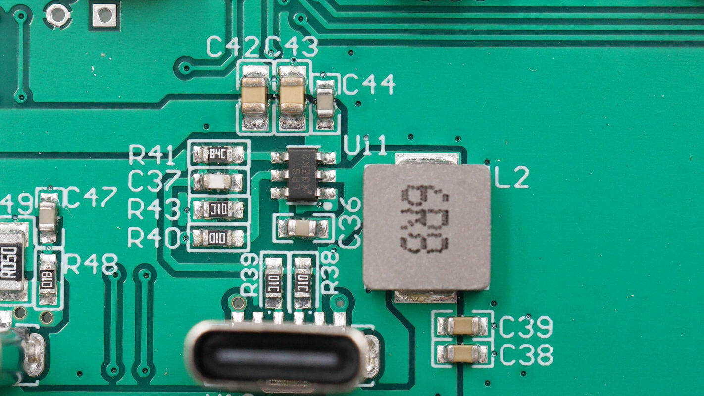
The synchronous buck converter is from LPS, marked K3EK2, and comes in a SOT23 package.
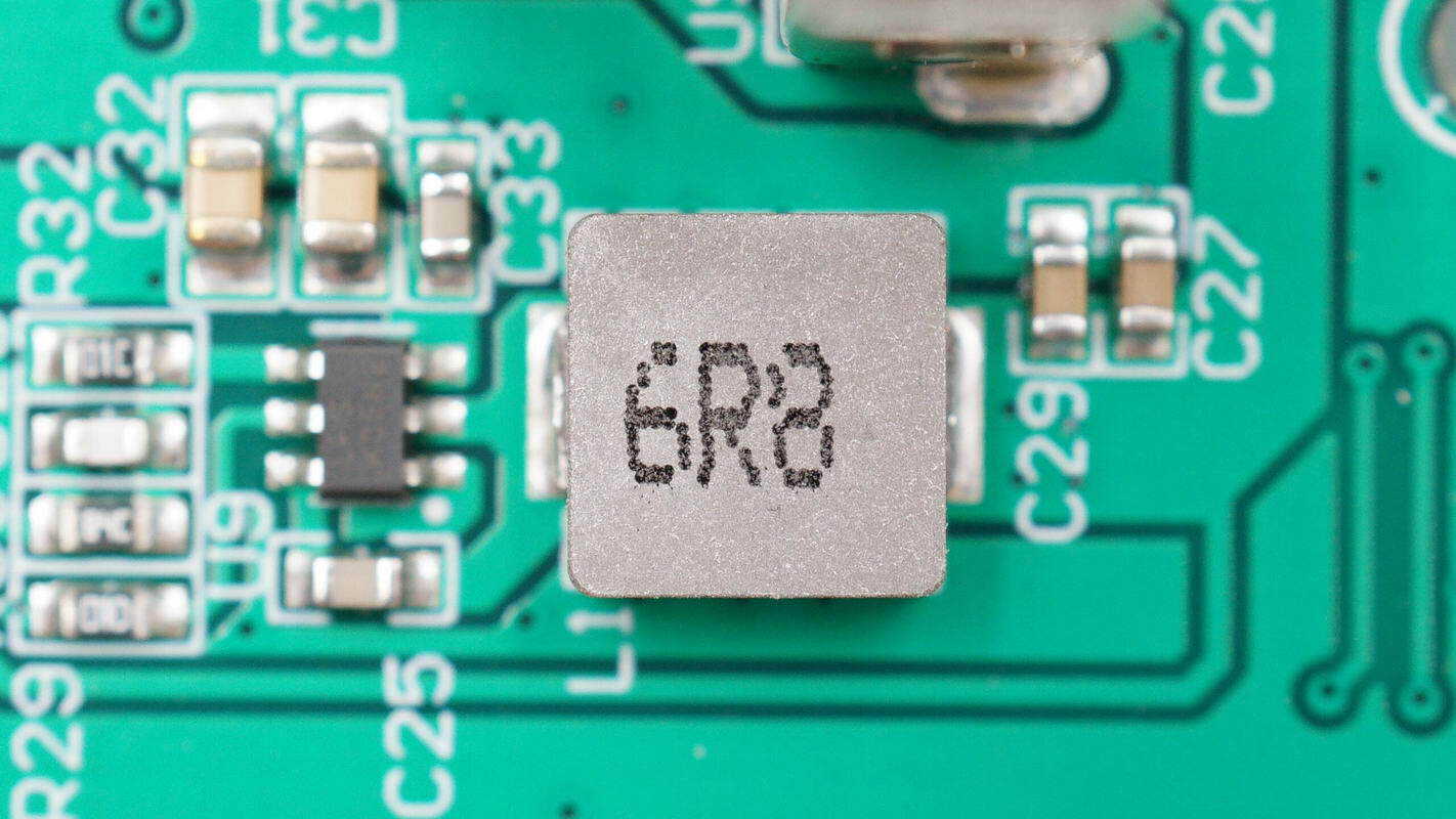
A close-up of the paired 6.8 μH alloy inductor.
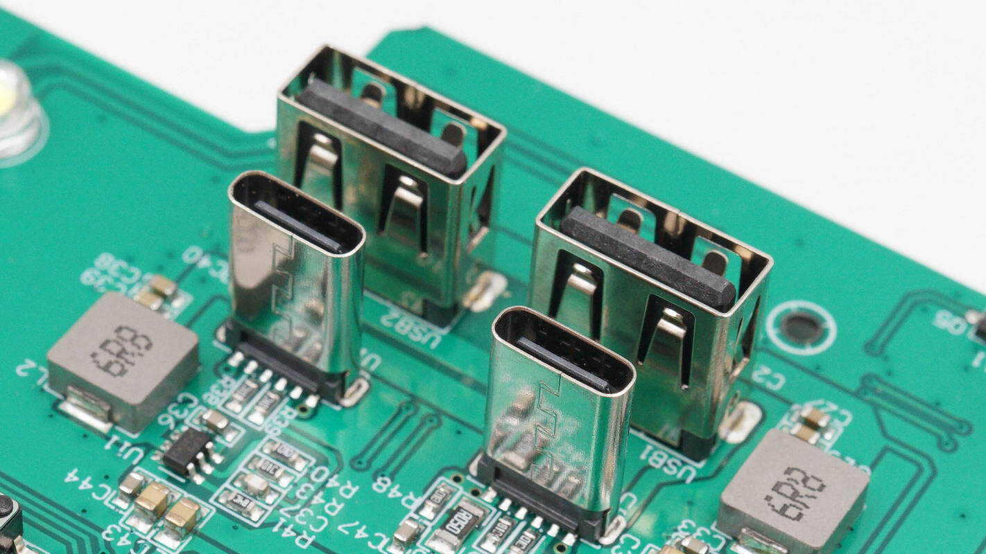
The USB-C and USB-A sockets are secured via through-hole soldering.

The charging port is connected via soldering.

The power-control MOSFET is an iCM CMT3400RM, NMOS, rated for 30 V with an on-resistance of 28 mΩ. It comes in a SOT23 package and is used to control the LED lighting.
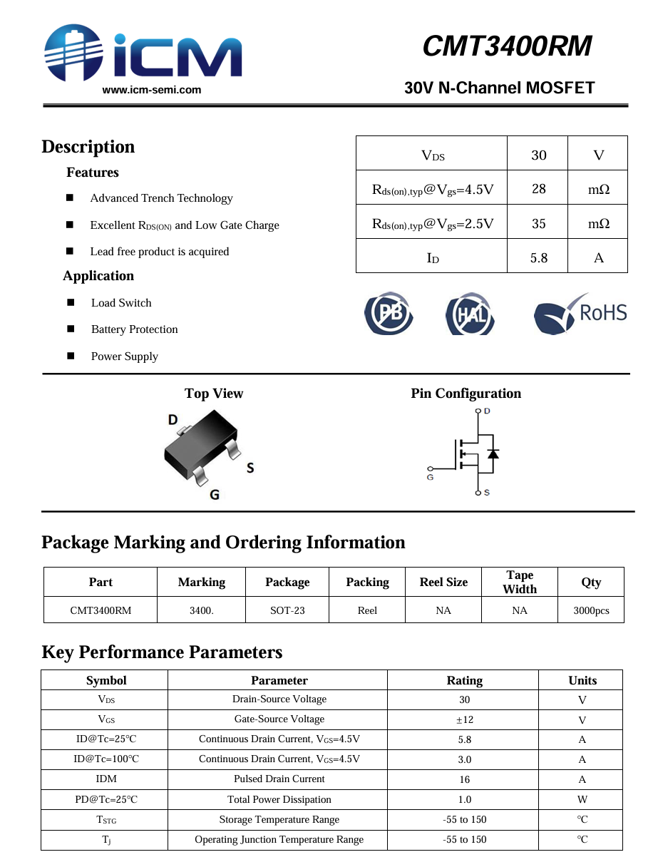
Here is the information about iCM CMT3400RM.

A close-up of the LED light.

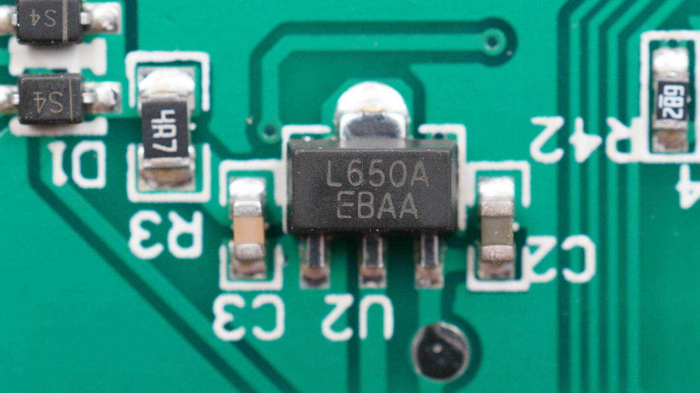
The voltage regulator chip is an iCM CM1842A50, marked L650A. It is a low-dropout linear regulator supporting an input voltage up to 45 V and an output current of 300 mA. It offers selectable fixed output voltages of 1.8 V, 3 V, 3.3 V, and 5 V, and features integrated short-circuit and thermal protection with excellent transient response. The chip comes in a SOT89 package.
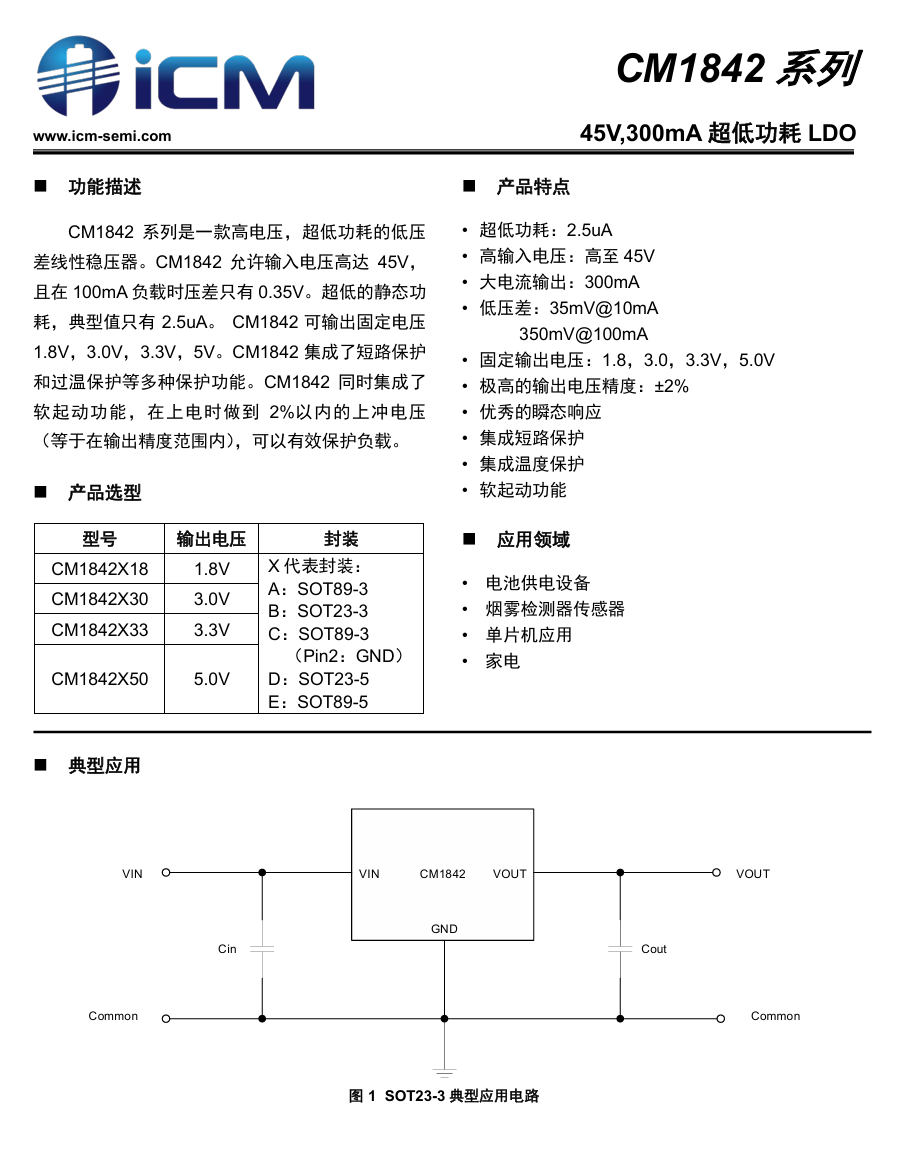
Here is the information about iCM CM1842.
Another voltage regulator chip is of the same model.
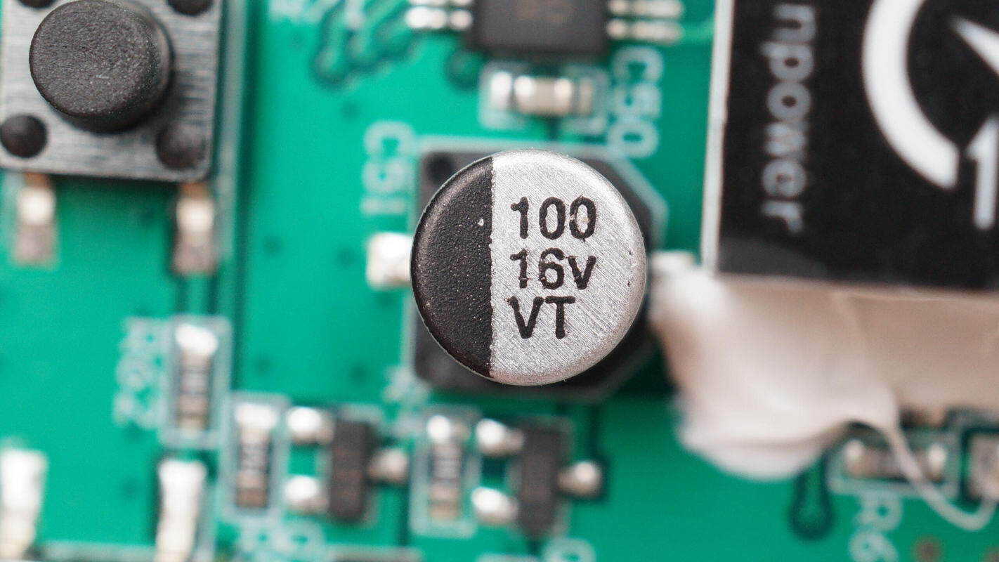
The filter capacitor is rated at 100 μF, 16 V.
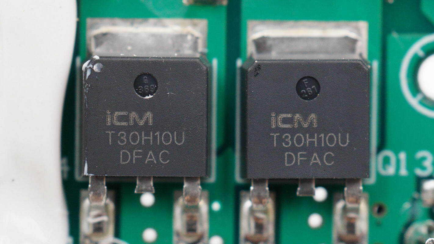
Two iCM CMT30H10U MOSFETs are used to control power to the air pump and fan.
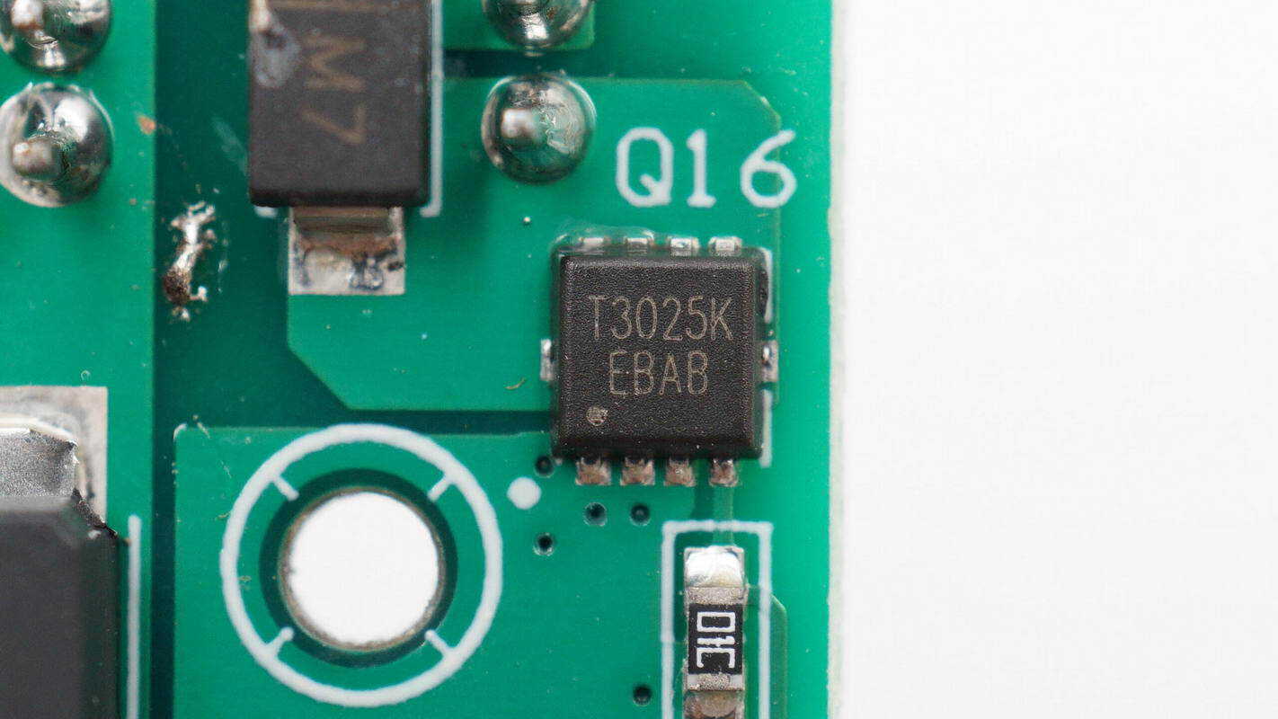
The MOSFET used to control the output relay is an iCM CMT3025K, NMOS, rated for 30 V with an on-resistance of 9 mΩ, and comes in a 3×3 mm PDFN package.
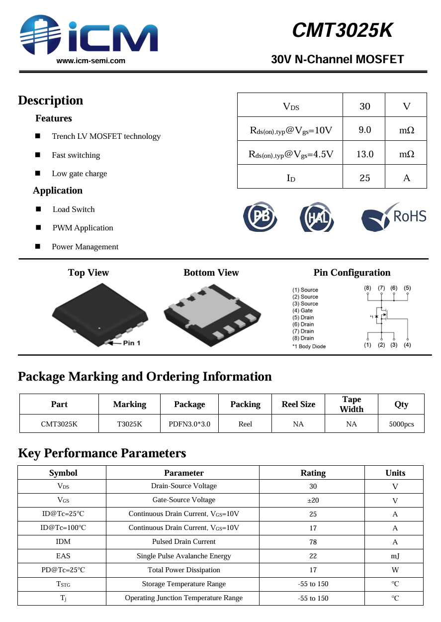
Here is the information about iCM CMT3025K.
A close-up of the three flyback diodes.
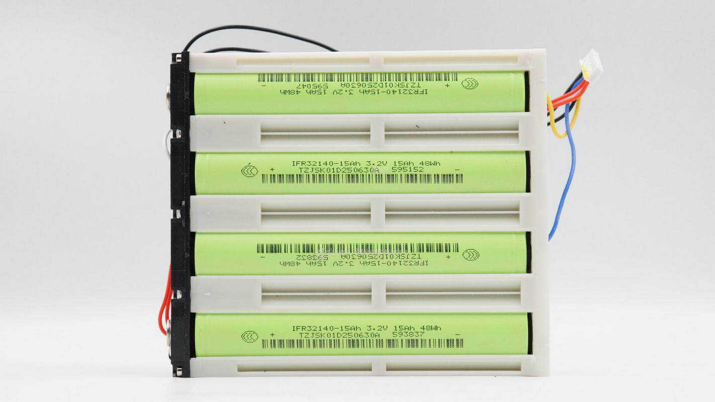
The LiFePO₄ battery cells are secured using a plastic frame.
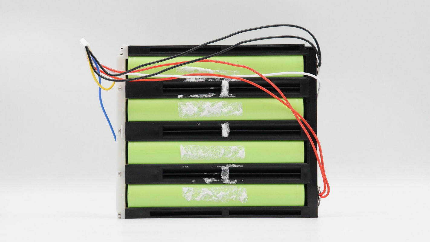
The other side of the battery pack is cushioned with foam and secured to the bracket.
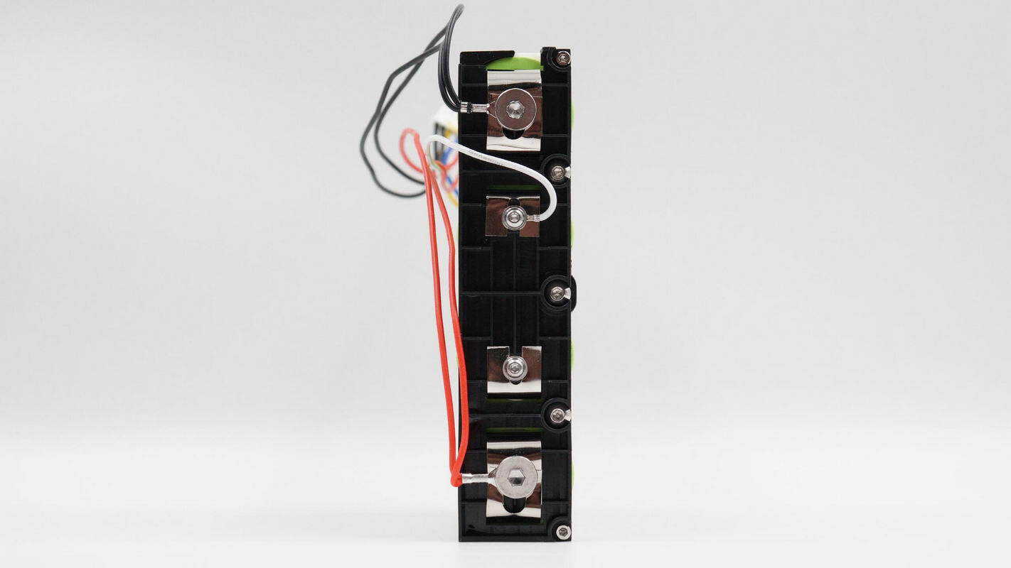
The frame is secured with screws, and the connecting wires are also fastened using screws.
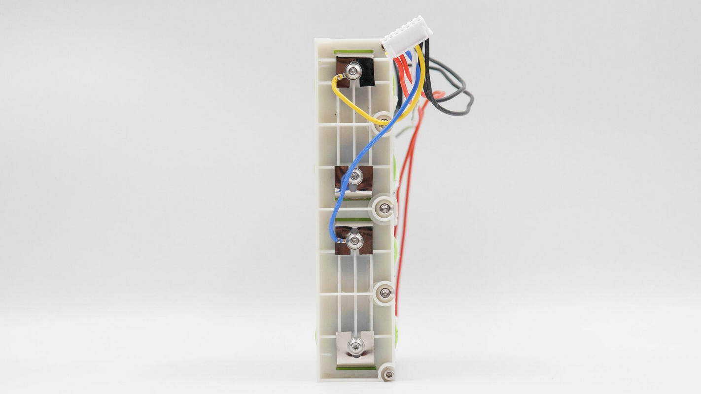
The wires on the other side are also secured with screws.
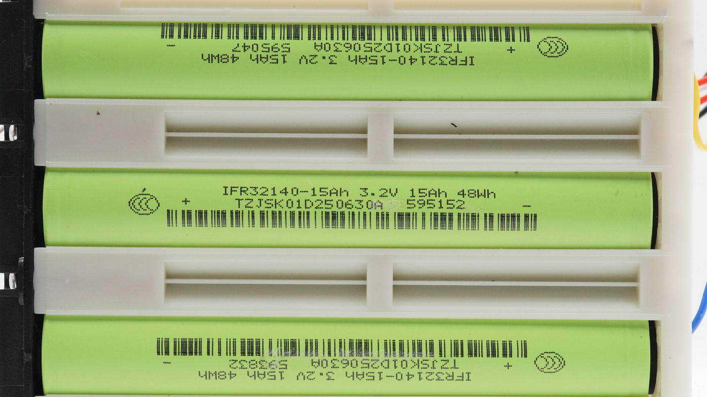
The LiFePO₄ battery cells are from JSK, model IFR32140-15Ah. Each cell has a nominal voltage of 3.2 V, a charge cutoff voltage of 3.65 V, a capacity of 15 Ah, a maximum continuous discharge current of 45 A, a pulse discharge current of 90 A, and an energy rating of 48 Wh.

The air pump assembly is secured with a clamping plate and is equipped with a pressure sensor.
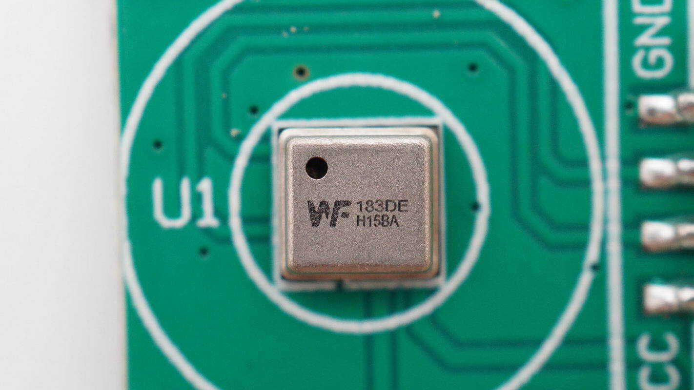
The pressure sensor is a WF WF183DE, a digital sensor supporting a 2.4–5.5 V operating voltage. It supports I²C, UART, and OWI interfaces and comes in a QFN8 package.
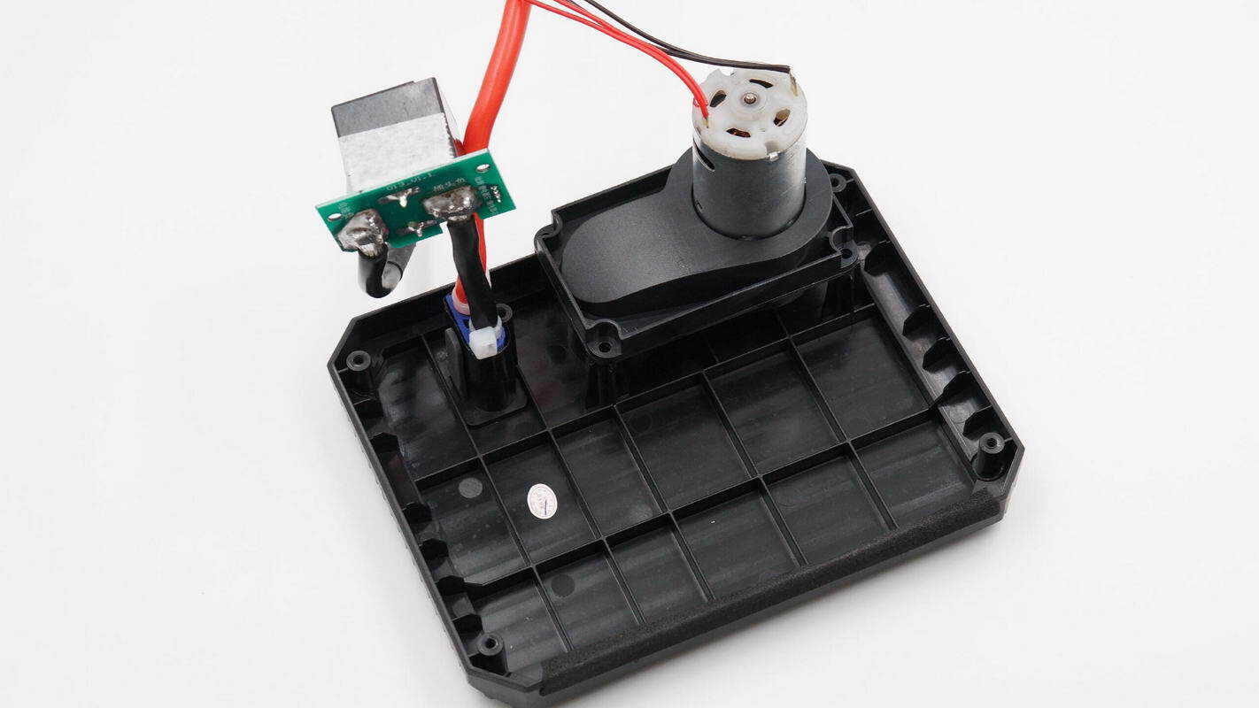
Inside the housing, there is a fan and a connection socket.

The fan features a centrifugal design.
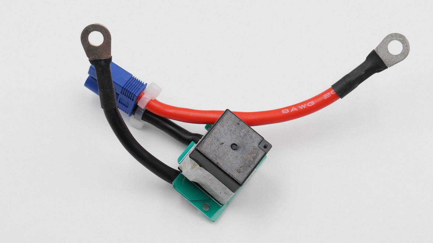
The EC5 connector terminals are controlled by a relay for output.
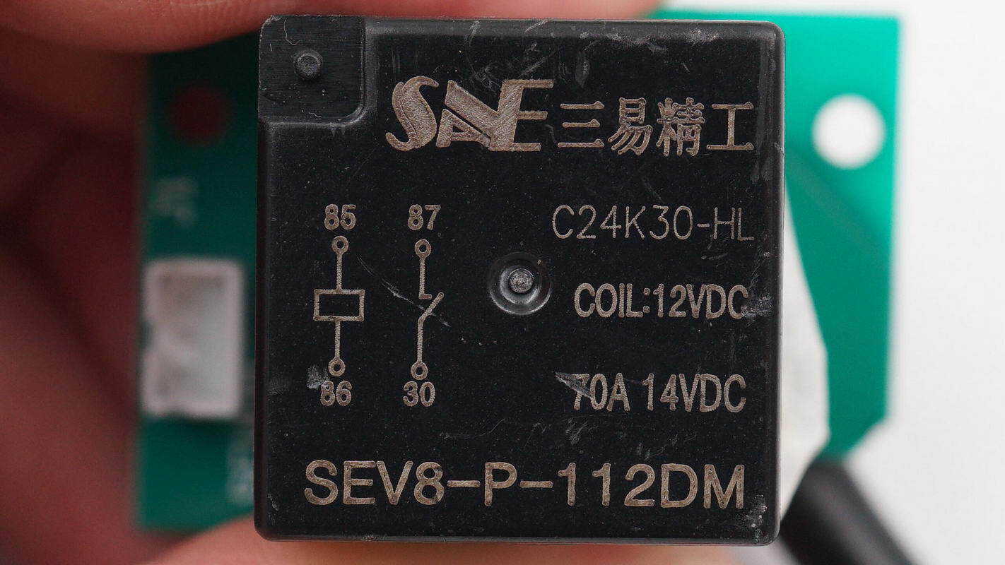
The relay is from STSYJG, model SEV8-P-112DM, with a 12 V coil voltage and a contact rating of 70 A at 14 V.

A close-up of the EC5 connector socket.
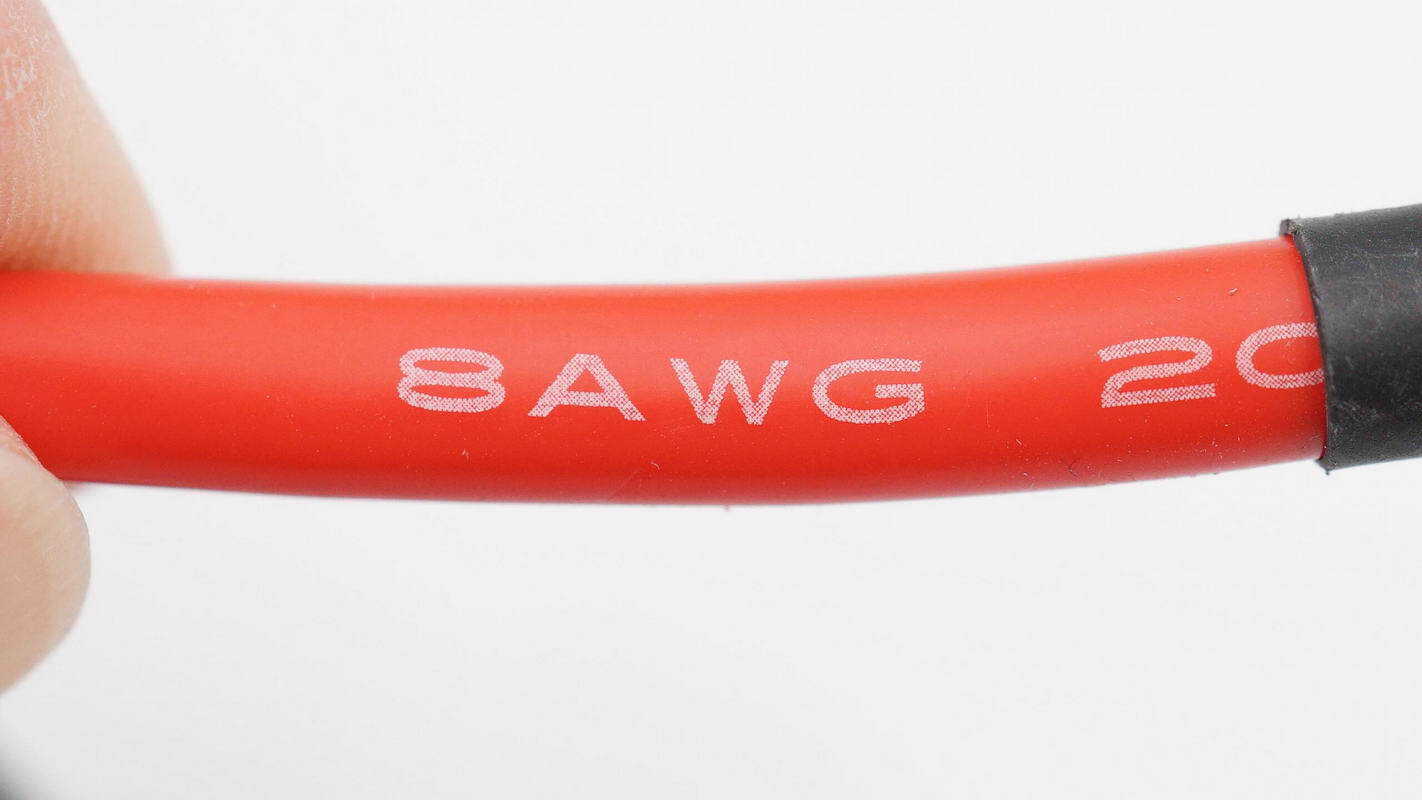
The silicone-insulated wires are 8AWG.
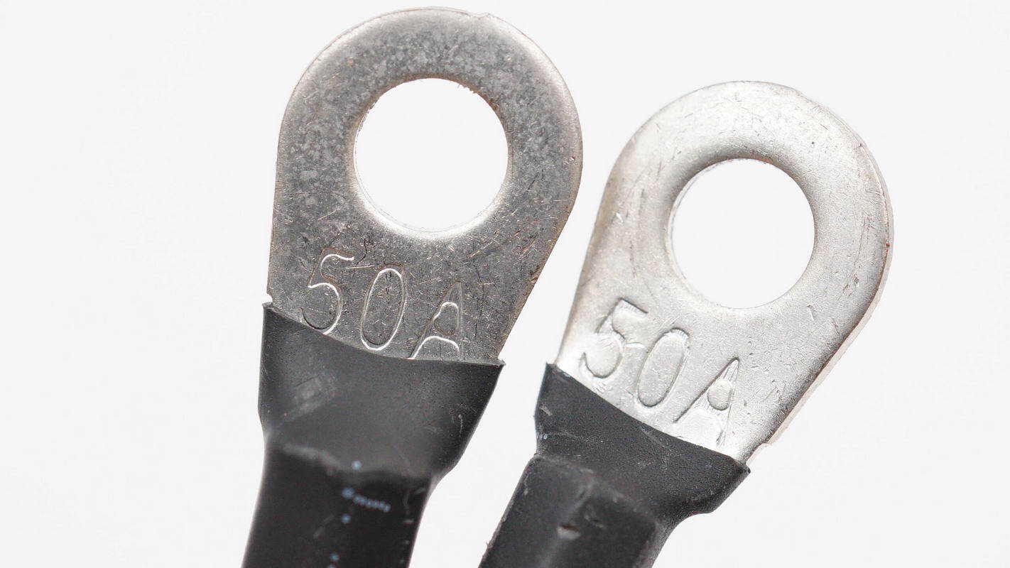
The connector terminals are rated for 50 A.
Well, those are all components of the Maxcellent Multi-Function Portable Jump Starter.
Summary of ChargerLAB
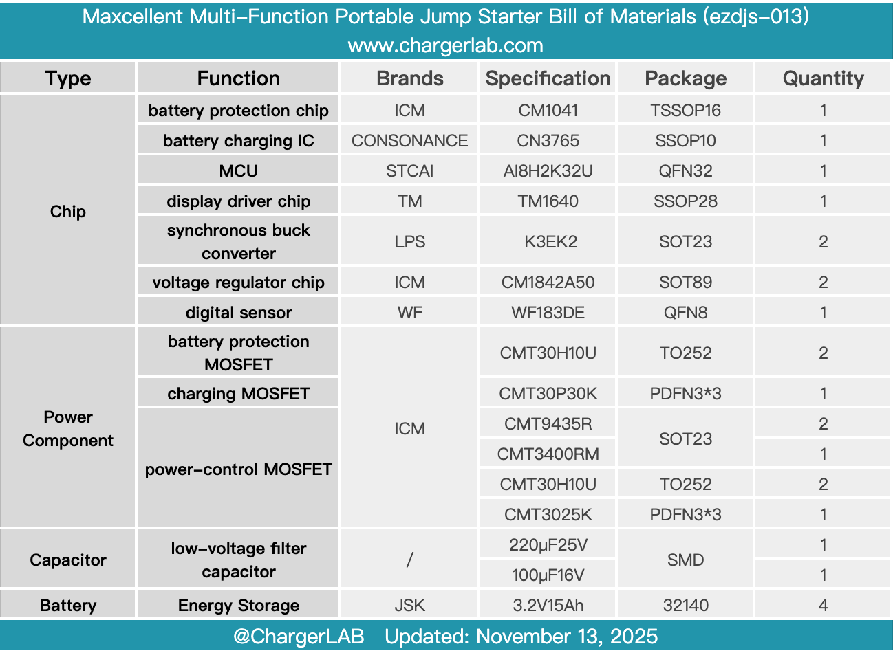
Here is the component list of the Maxcellent Multi-Function Portable Jump Starter for your convenience.
It features an emergency jump-start function, supports tire inflation and DC output, and is equipped with USB-C and USB-A ports. While enabling vehicle emergency starting, it can also inflate air mattresses, kayaks, and swim rings, as well as charge mobile phones, offering a comprehensive and versatile set of functions.
After taking it apart, we found that it contains built-in JSK LiFePO₄ batteries arranged in a 4-series configuration, each with a capacity of 15 Ah, secured within an insulating frame. The battery protection chip is an iCM CM1041, paired with iCM CMT30H10U MOSFETs. The battery charging IC is a CONSONANCE CN3765, used in conjunction with an iCM CMT30P30K MOSFET.
The MCU is an STCAI AI8H2K32U, powered by an iCM CM1842A50 voltage regulator. Screen driving is handled by a TM TM1640. The MOSFETs controlling power to the air pump and fan are also iCM CMT30H10U. iCM has now expanded its LDO and power device product lines, providing customers with more options.
Related Articles:
1. Teardown of CUKTECH 10 Super Magnetic Power Card (WPB100P)
2. Teardown of UGREEN Nexode 160W 5-Port GaN Charger (X774)
3. Teardown of Xiaomi 67W 20000mAh Power Bank with Integrated Cable (PB2067)