Introduction
Today, we will take apart the Great Wall GW-CRPS800N2 server redundant power supply. It supports 100–240V AC input and 240V HVDC input. The main output voltage of the power supply is 12V with a rated output current of 65A, while the standby output provides 12V at 3A. It features Platinum-level conversion efficiency and utilizes a PFC + LLC + synchronous rectification architecture. The power supply also supports PMBus communication. Let’s take a look at its internal design and components.
Product Appearance
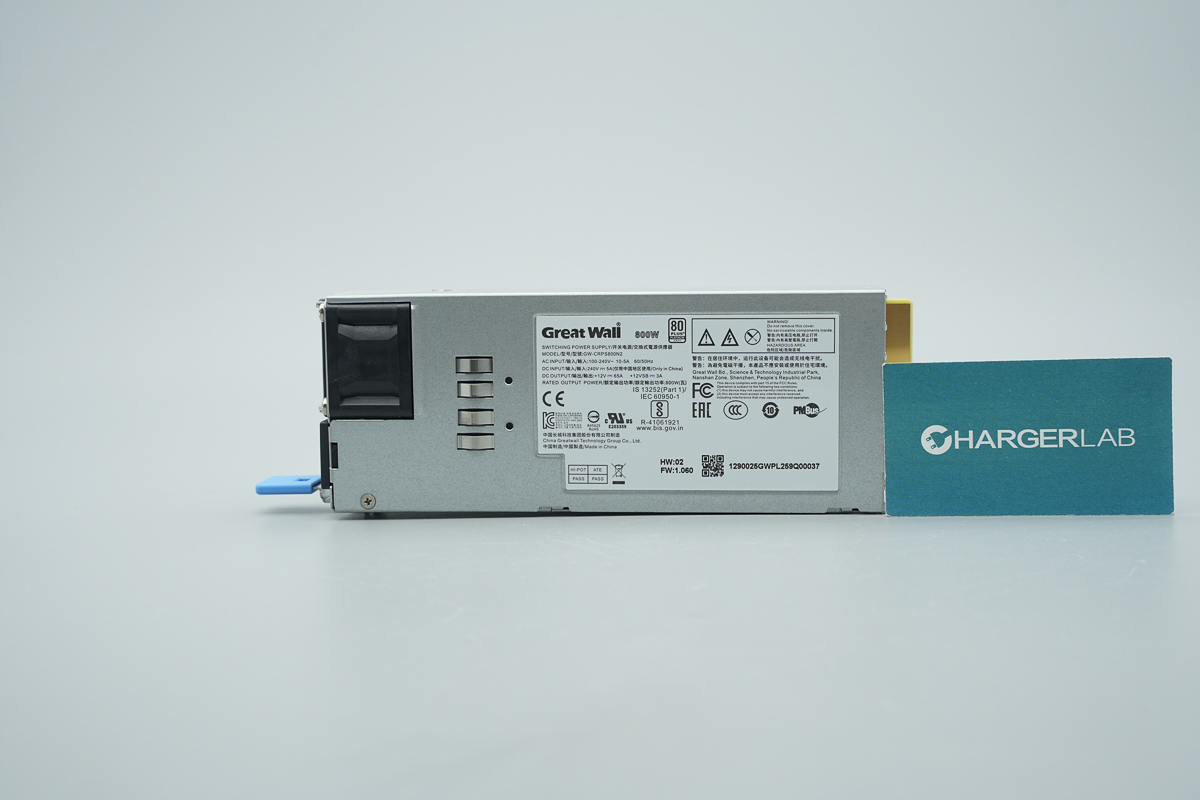
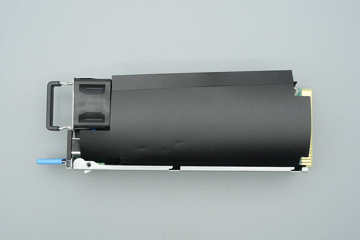
It features a galvanized steel enclosure with a label affixed to the front.
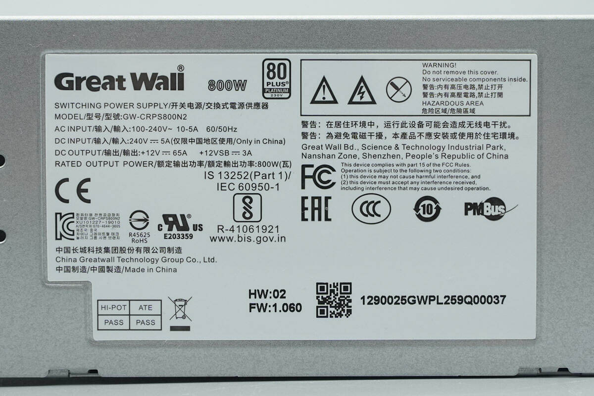
Model: GW-CRPS800N2
Input: 100-240V~ 10-5A 60/50Hz
Input: 240V ⎓ 5A (For use in China only)
Output: +12V ⎓ 65A, +12VSB ⎓ 3A
Rated Output Power: 800W
Certified 80 PLUS Platinum.
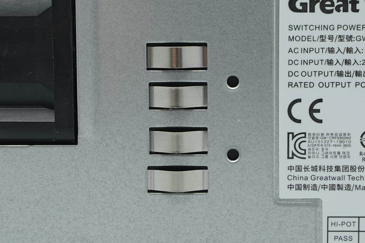
Close-up of the front grounding clips.
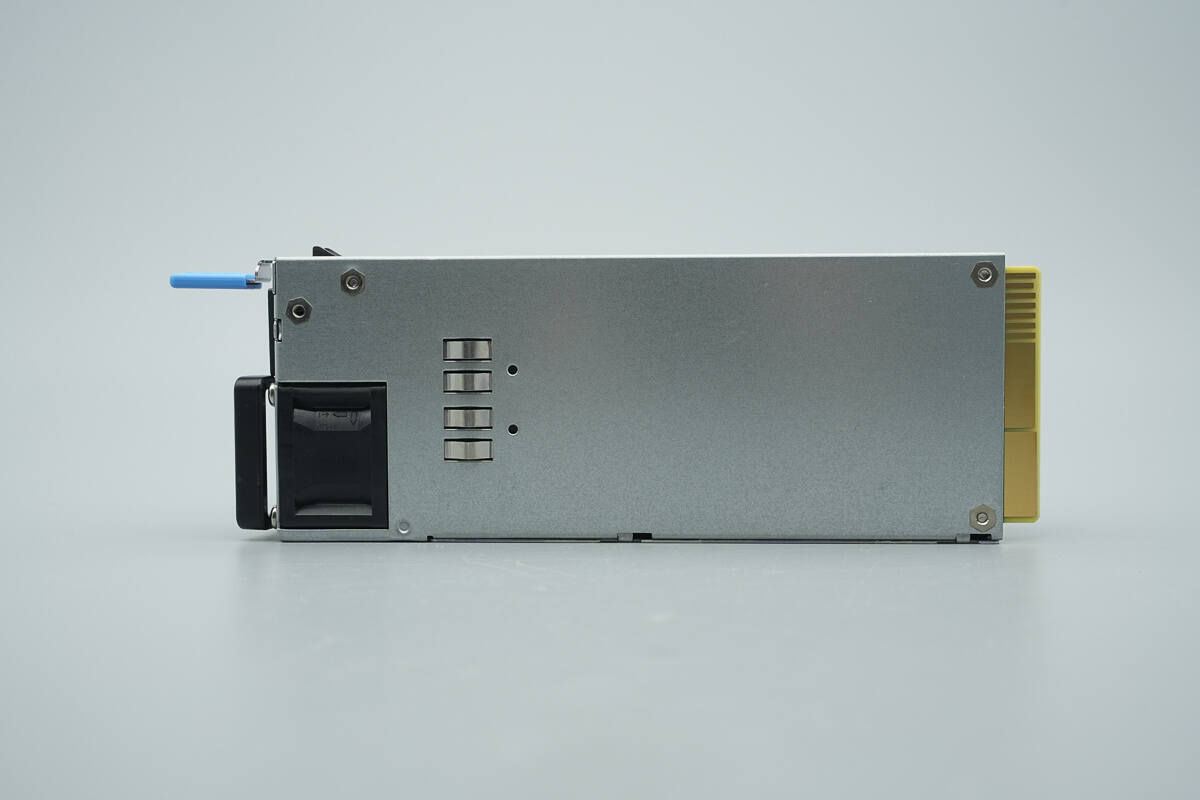
Grounding clips are also provided on the rear.
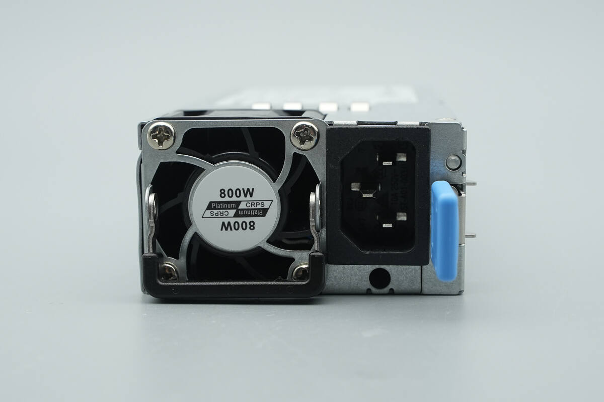
The input side is equipped with a handle, a cooling fan, an input socket, an indicator light, and a trip lever.
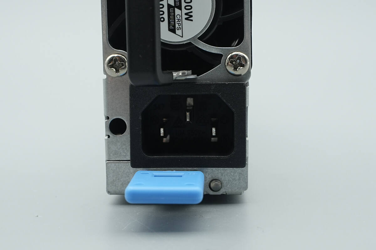
The input uses a three-prong connector.
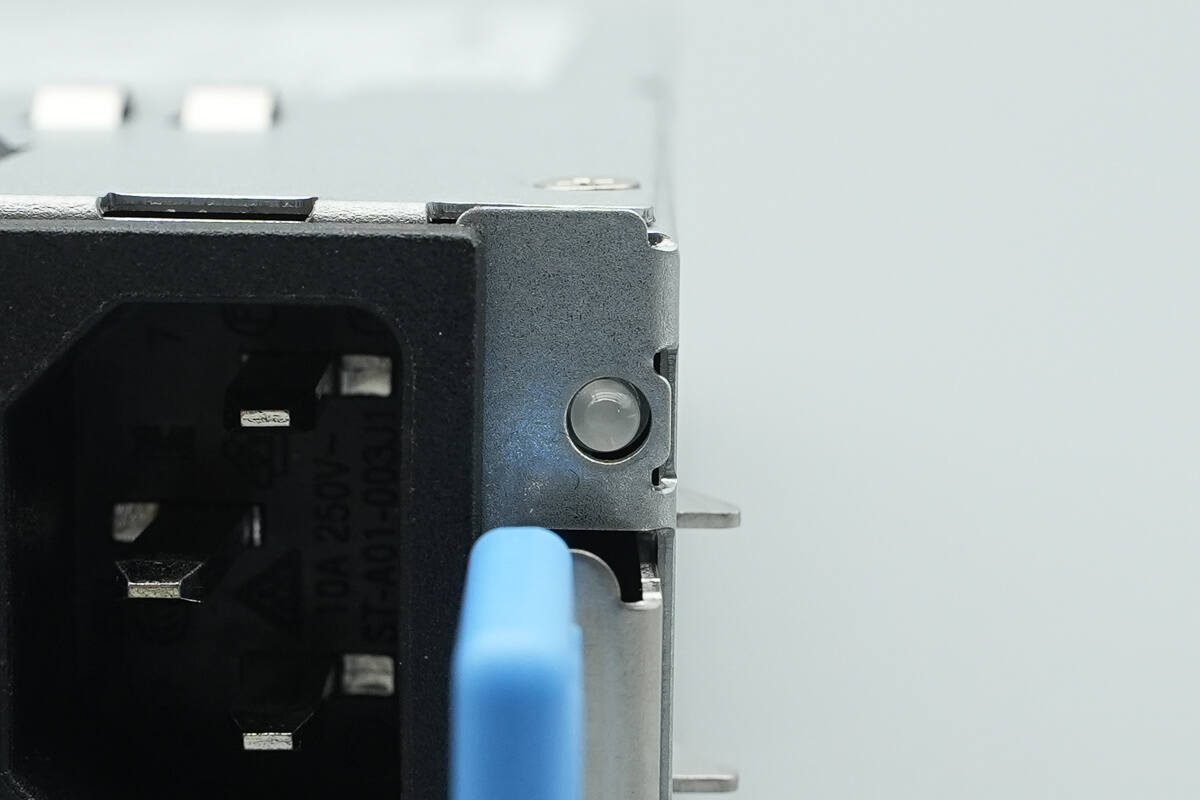
The LED indicator shows the operational status of the power supply.
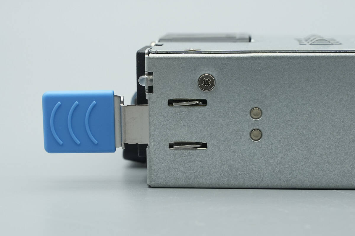
Close-up of the release lever.
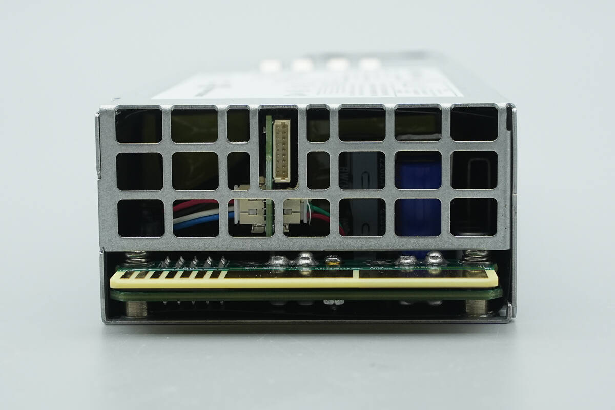
The output side is equipped with a grille and a gold finger connector.
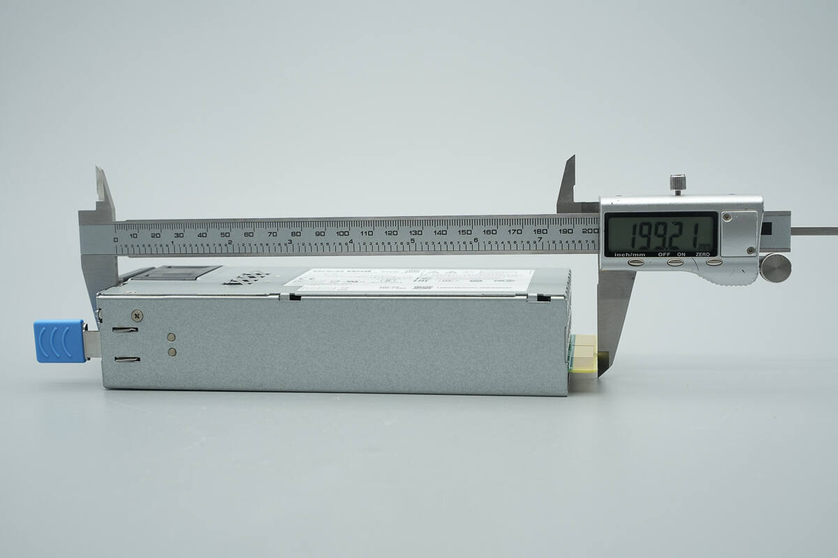
The length of the module is about 199.2 mm (7.84 inches).
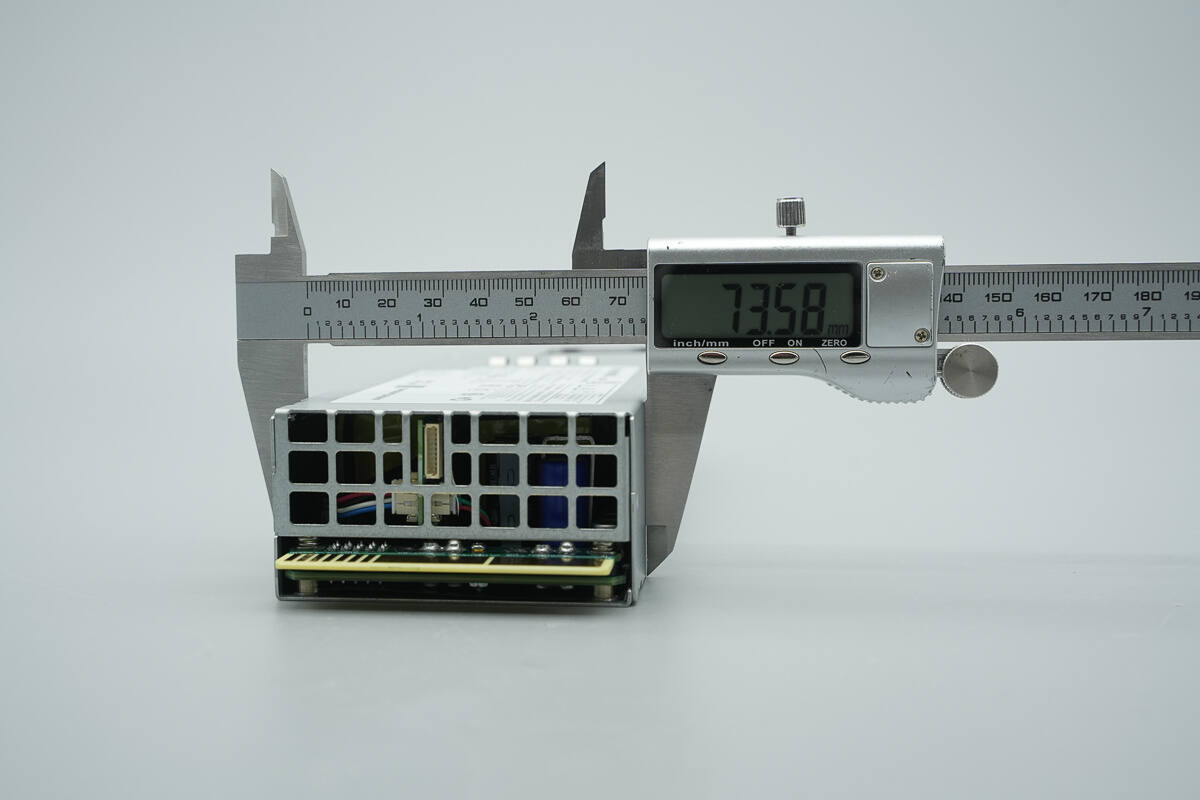
The width is about 73.6 mm (2.9 inches).
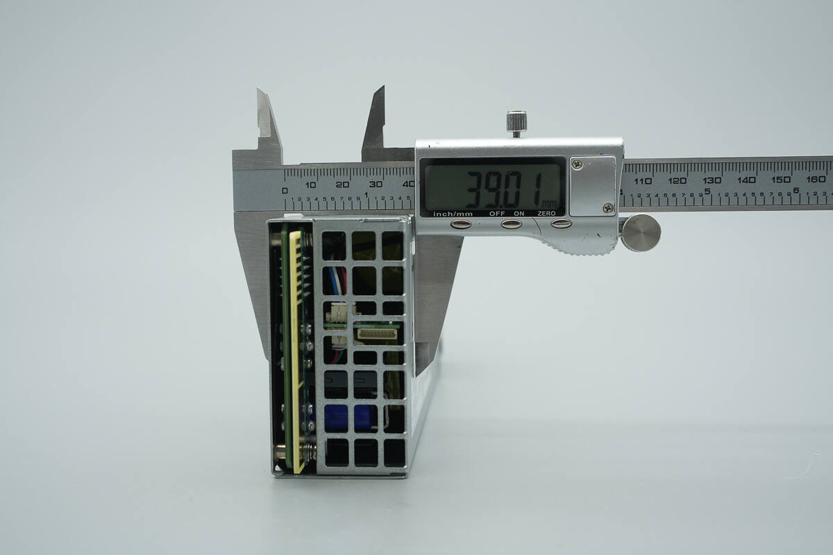
The thickness is about 39 mm (1.54 inches).
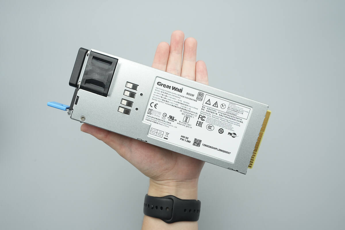
That's how big it is in the hand.
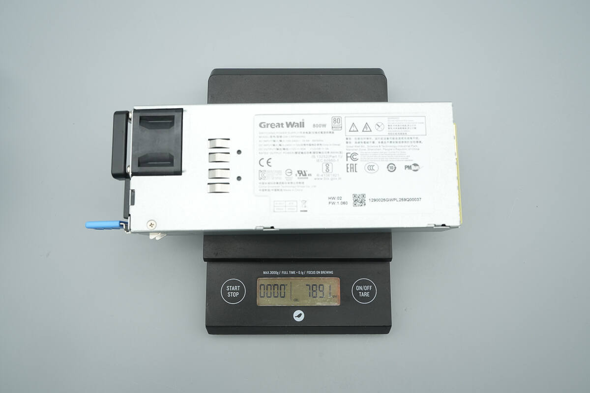
The weight is about 789 g (27.83 oz).
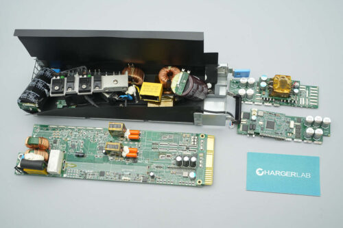
Teardown
Next, let's take it apart to see its internal components and structure.
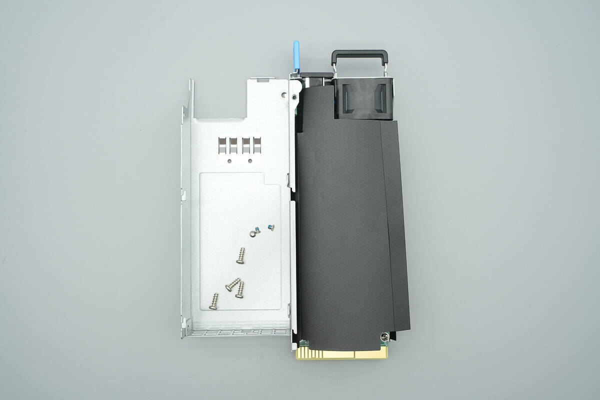
Unscrew the screws and remove the enclosure.
The PCBA module is insulated with a Mylar sheet.
The PCBA module is secured with screws.
The fan and indicator light are connected to a vertically mounted small PCB.
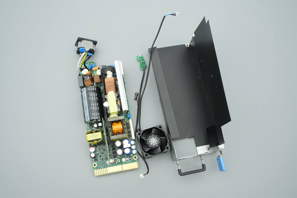
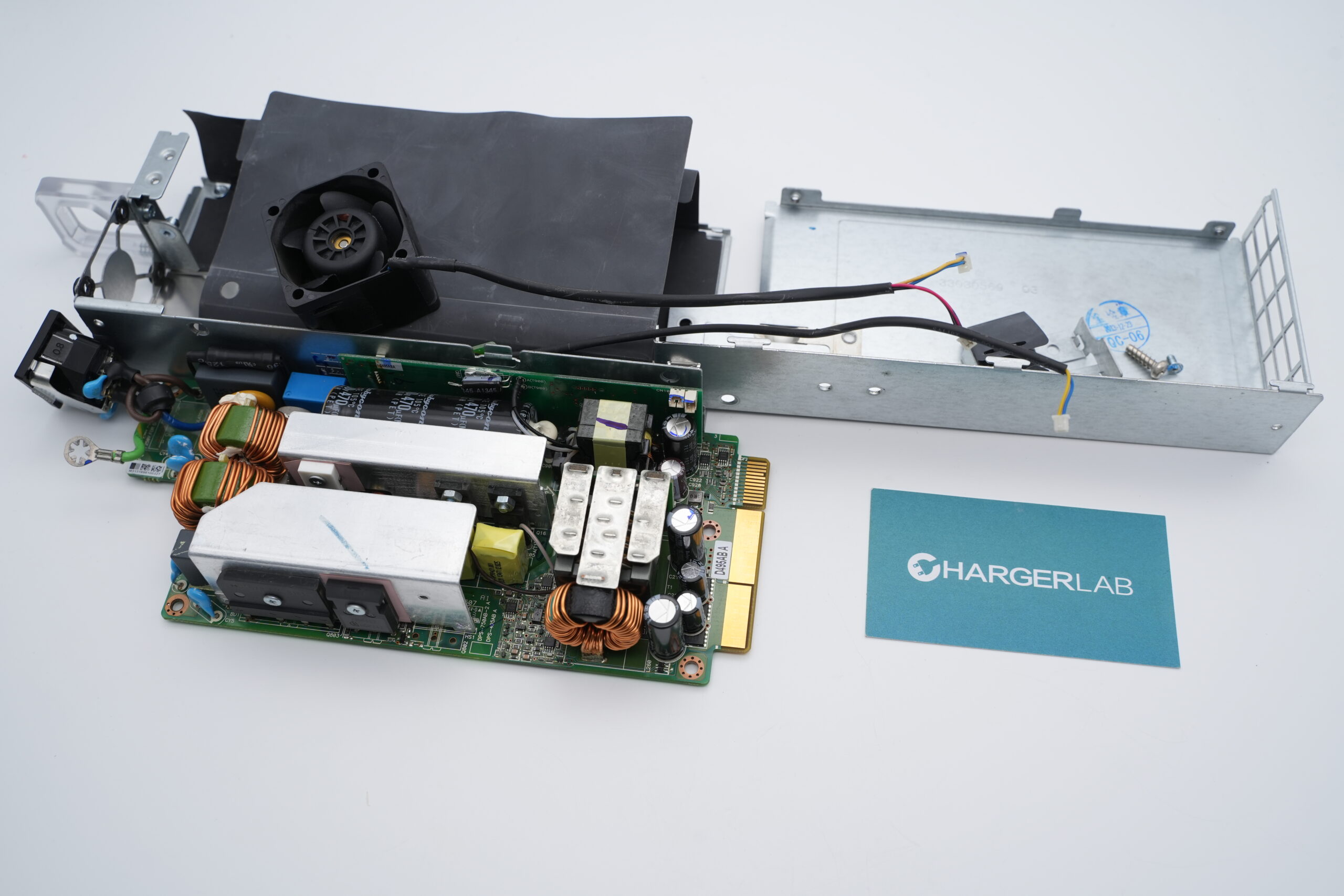
Remove the PCBA module.
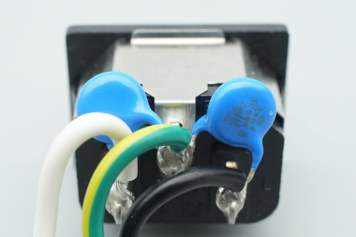
At the input side, the blue Y-capacitors are from Walsin, part number AC222M.
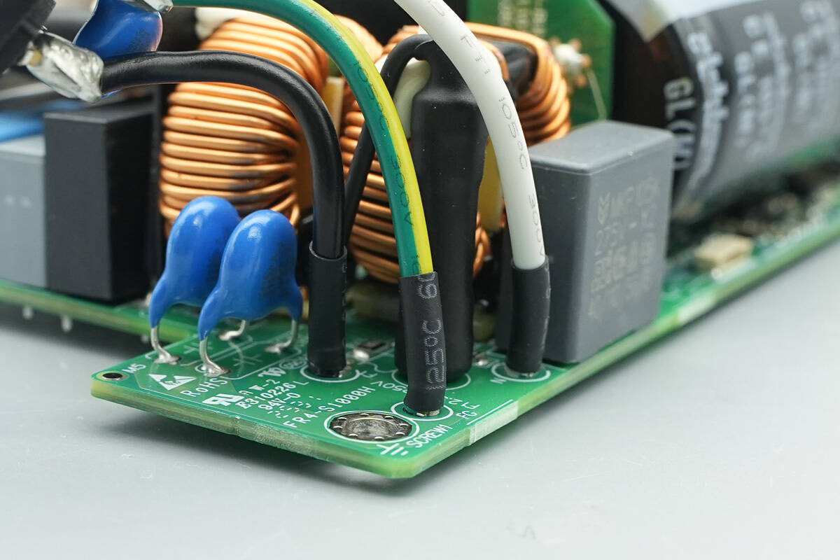
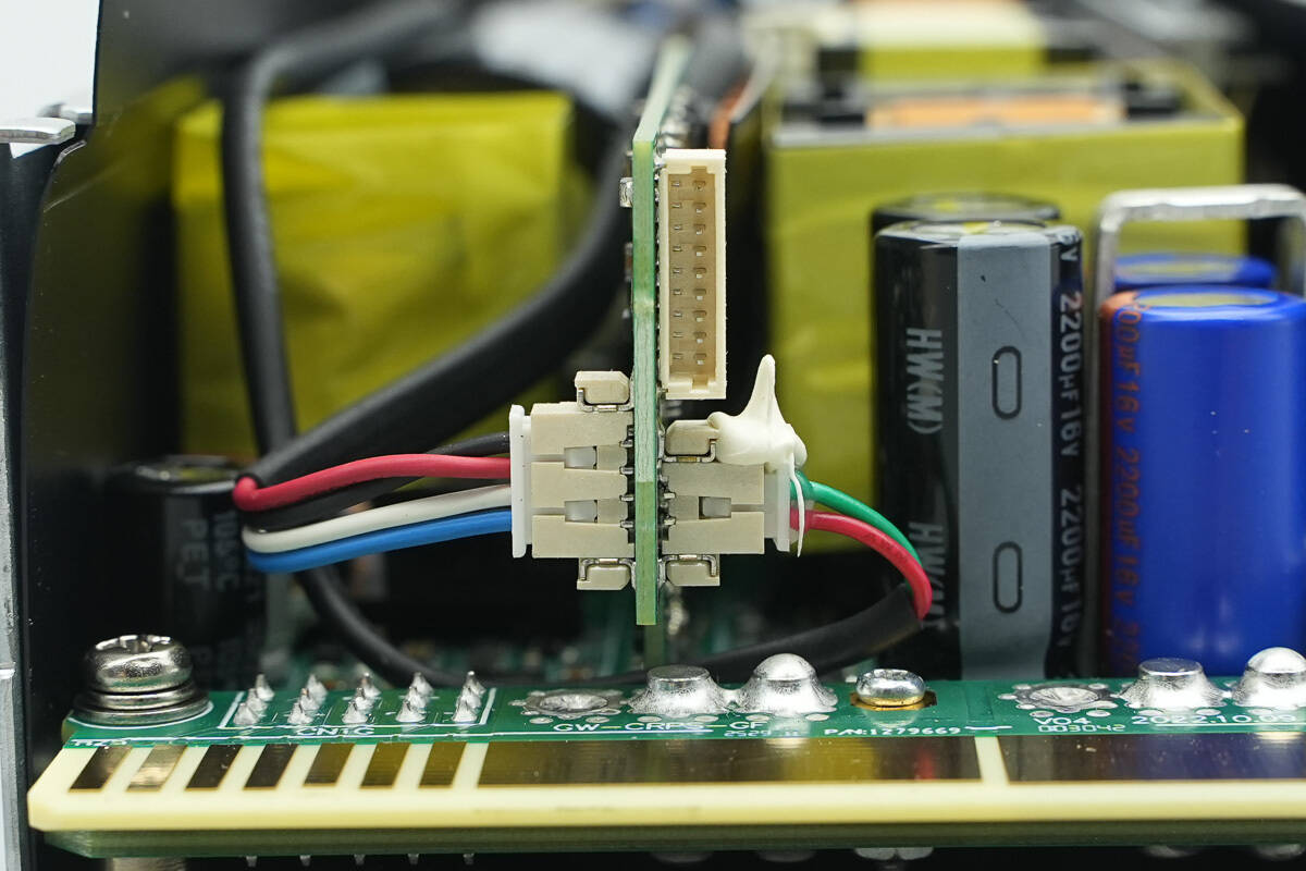
Wires are soldered to the PCBA module, with crimped terminals at the ends and insulated with heat-shrink tubing.
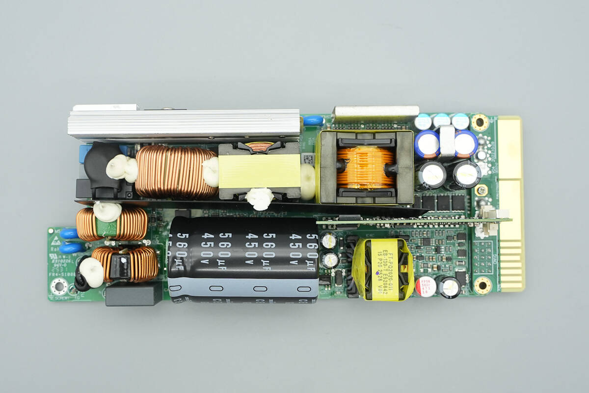
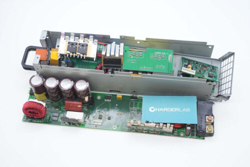
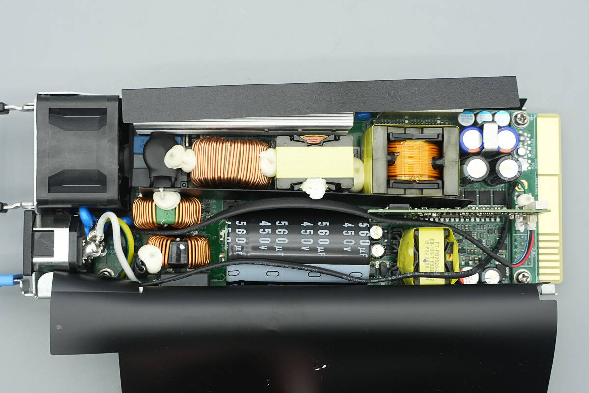
The front side of the PCBA module contains components such as a fuse, safety X2 capacitors, common-mode chokes, bridge rectifier, PFC MOSFETs, PFC rectifier, LLC MOSFETs, relay, PFC boost inductor, resonant inductor, and high-voltage filter capacitor.
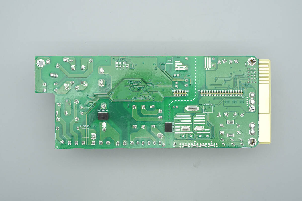
The rear side has rubber pads, and the primary and secondary sections are separated by a dashed line.
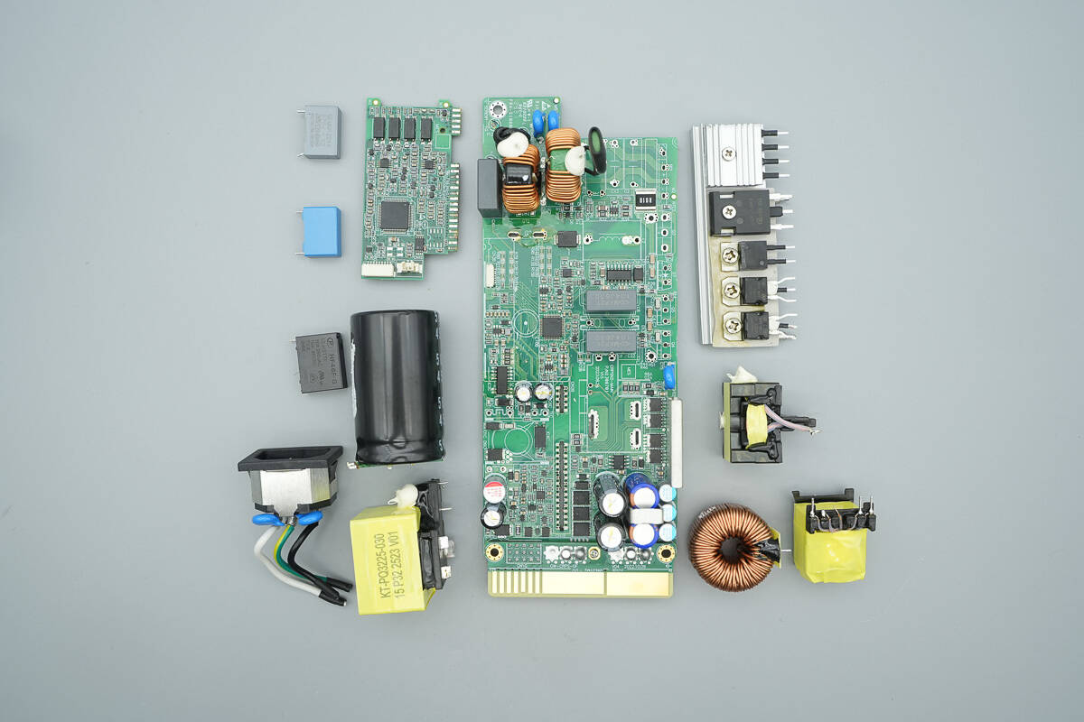
Remove the heatsink, high-voltage filter capacitor, PFC boost inductor, and other components to continue disassembly.
The input-side fuse is insulated with heat-shrink tubing.
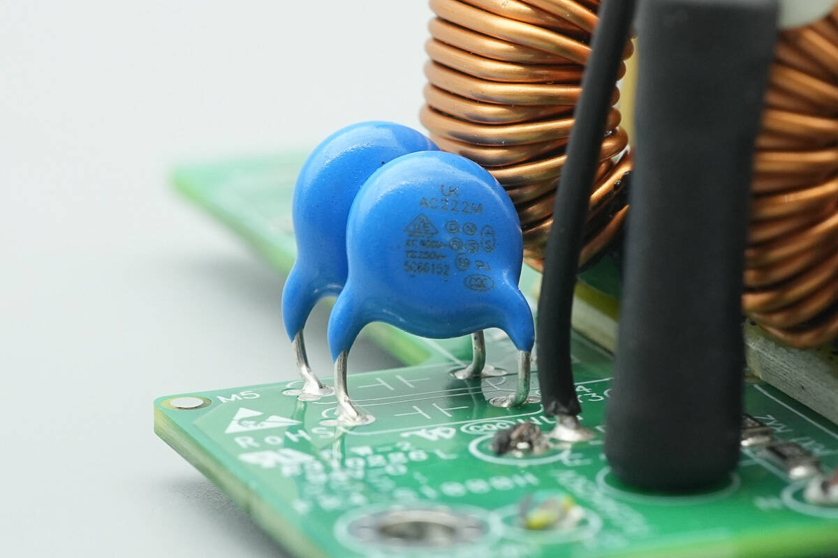
The blue Y-capacitors are from Walsin, part number AC222M.
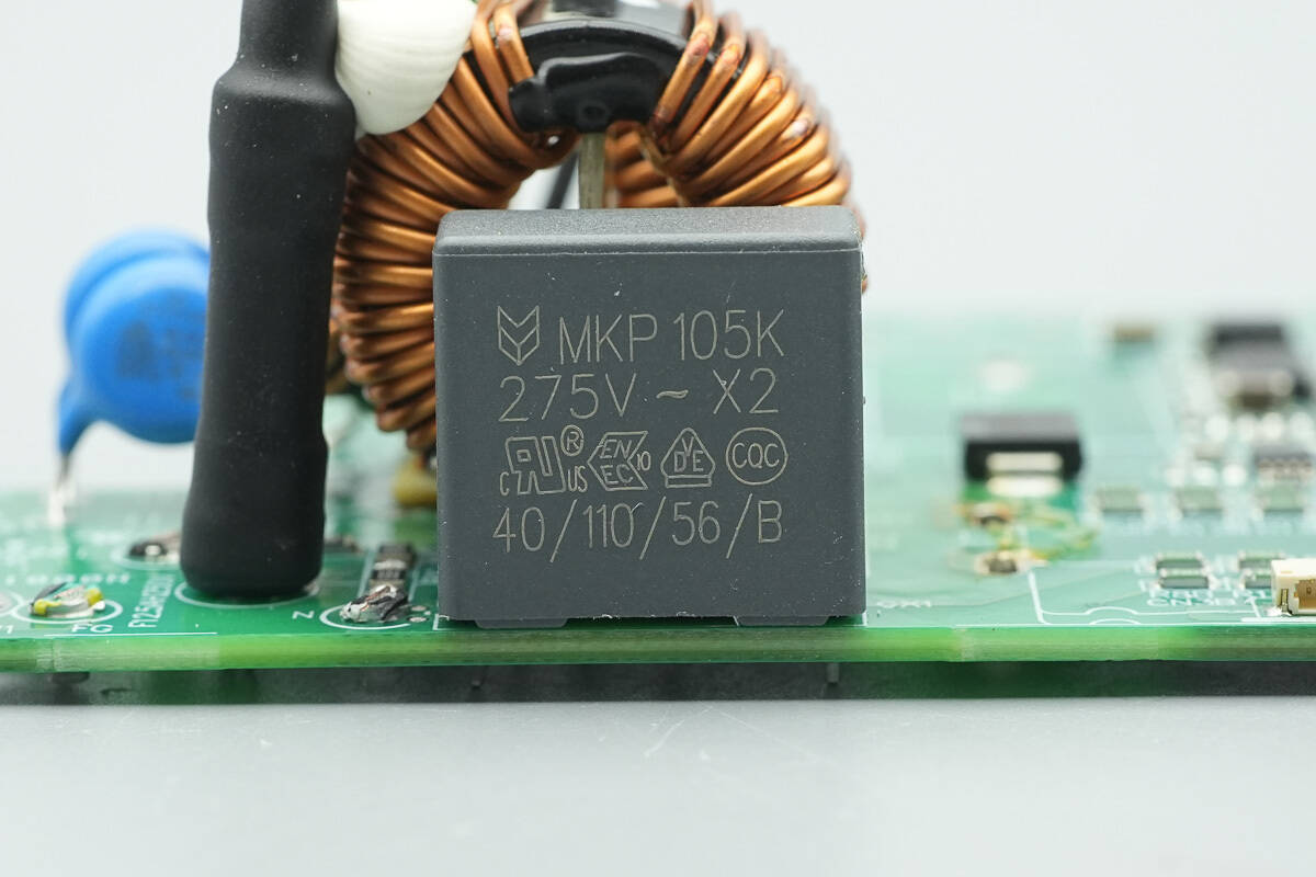
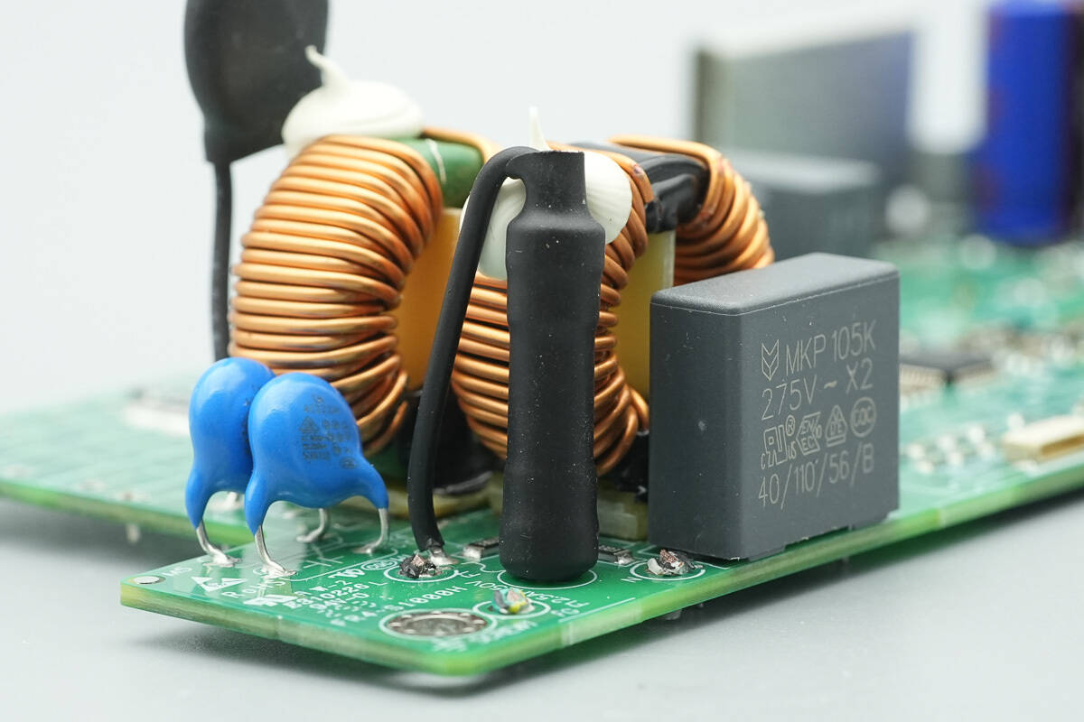
The safety X2 capacitor has a specification of 1 μF.
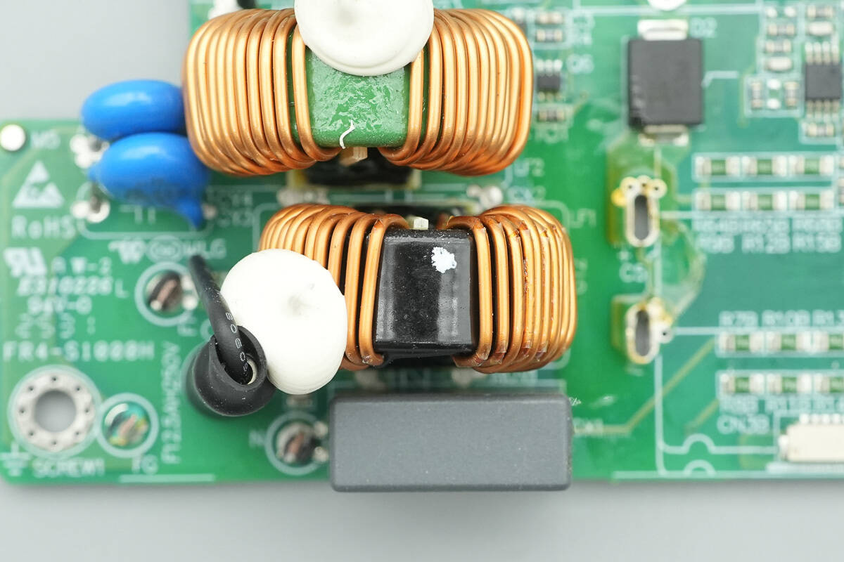
The common-mode choke is wound with enameled wire.
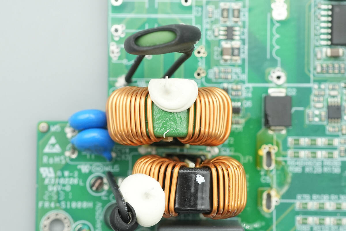
The other common-mode choke is also wound with enameled wire.
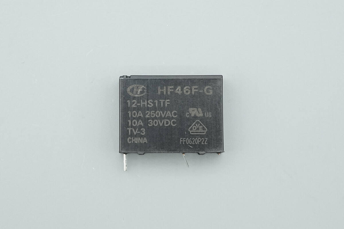
The relay is from HONGFA, model HF46F-G/12-HS1TF. It is an ultra-compact, medium-power relay with a single normally open contact, a switching capacity of 10 A, and a coil voltage of 12 V.
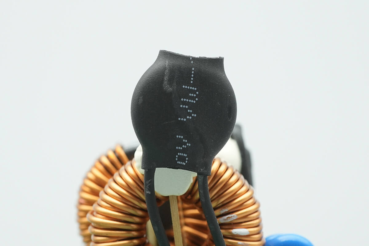
The NTC thermistor is insulated with heat-shrink tubing.
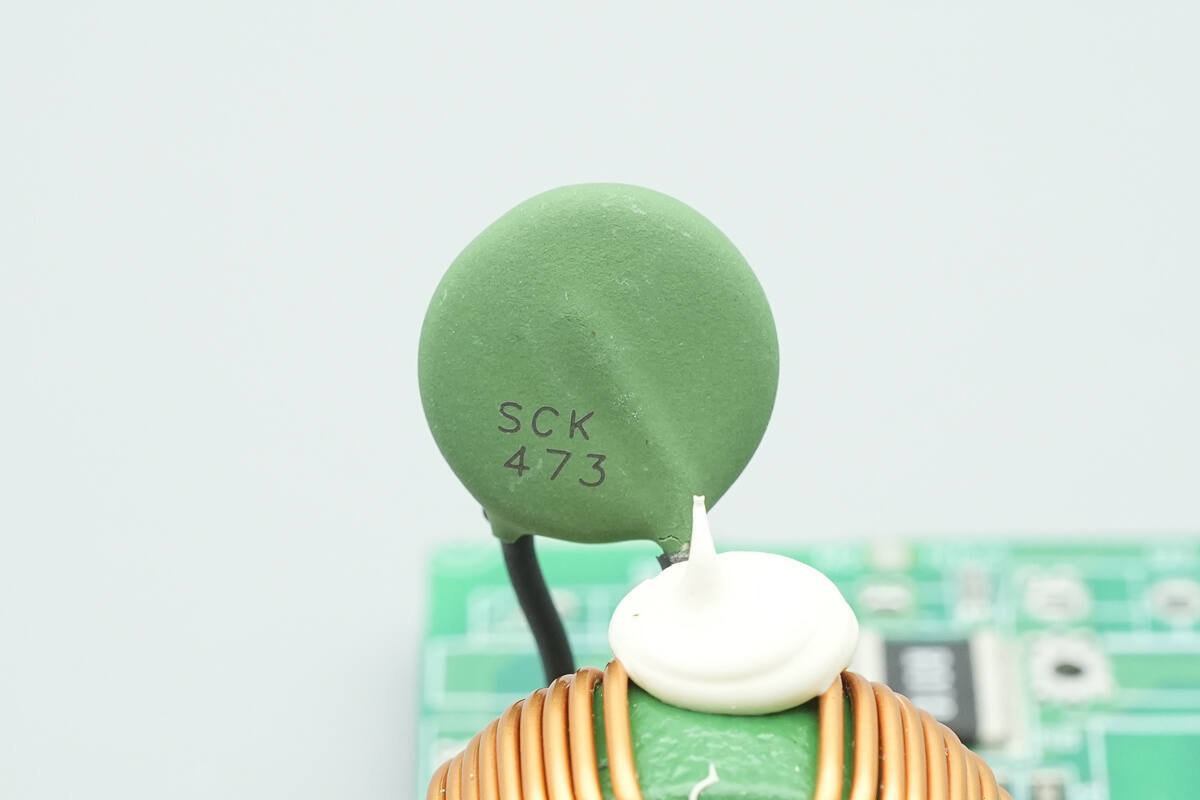
The thermistor is marked with SCK473.
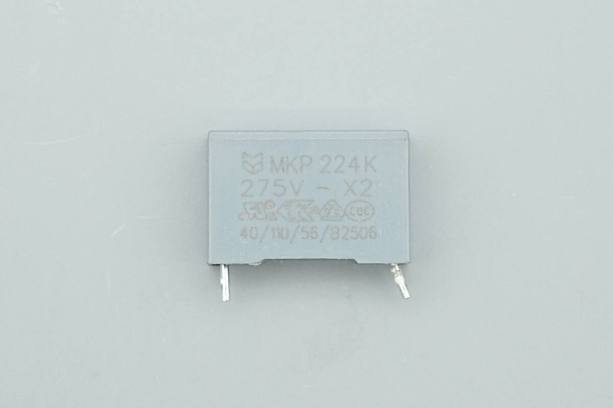
The safety X2 capacitor has a specification of 0.22 μF.
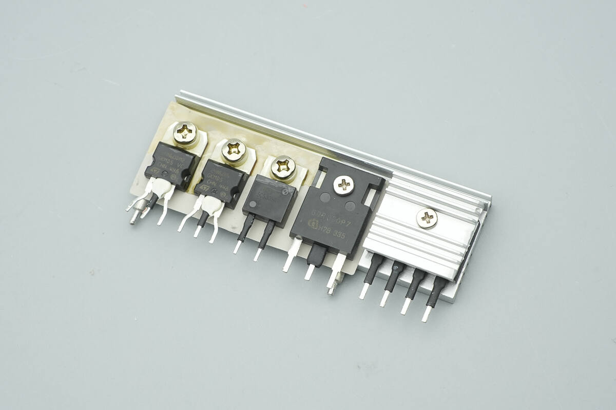
The heatsink carries the LLC MOSFETs, PFC rectifier, PFC MOSFETs, and bridge rectifier.
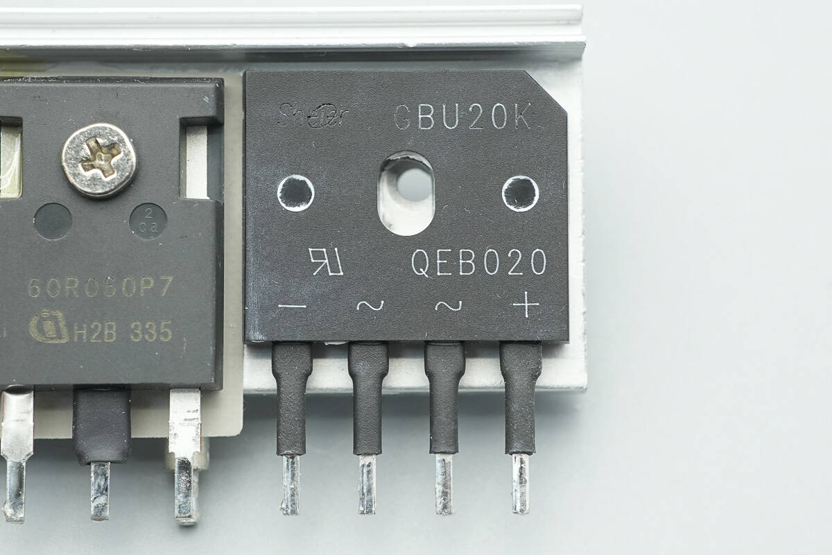
The bridge rectifier is from Sheier, model GBU20K, rated 800 V/20 A, and uses a GBU package.
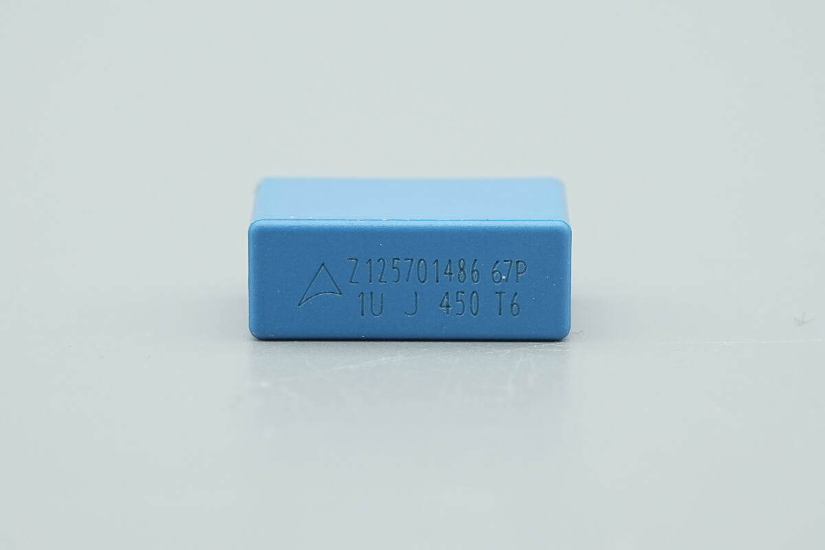
The film capacitor is from TDK, with a specification of 1 μF, 450 V.
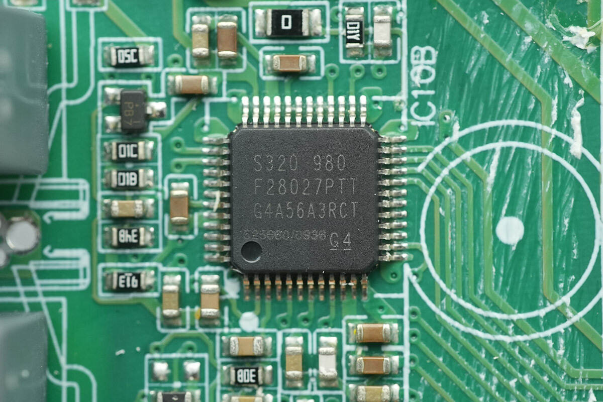
The primary controller is from TI, model TMS320F28027PT. It features a high-performance 32-bit CPU with a 60 MHz clock, 64 KB of FLASH, and 12 KB of SARAM. It supports 8-channel PWM output and offers I²C, SPI, and UART communication interfaces, packaged in an LQFP48.
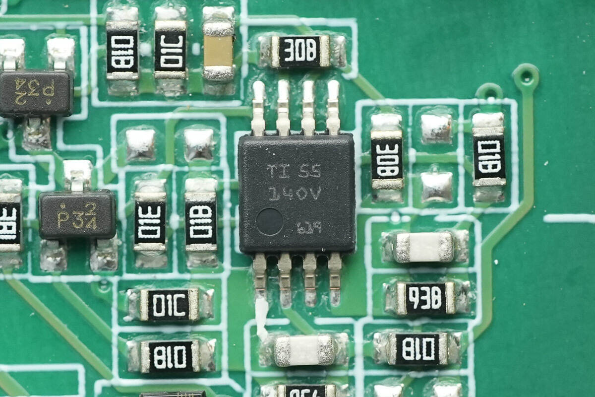
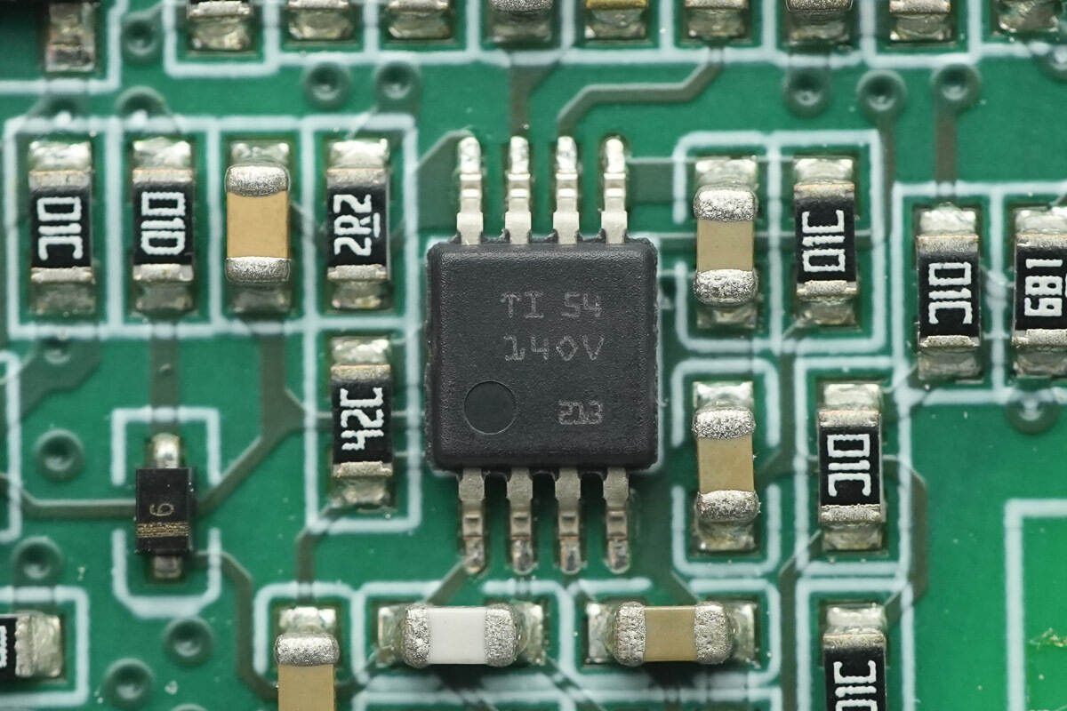
The operational amplifier is from TI, marked 14OV, model TLV2171. It is a dual low-power op-amp, supports a 36 V operating voltage, and comes in a VSSOP8 package.
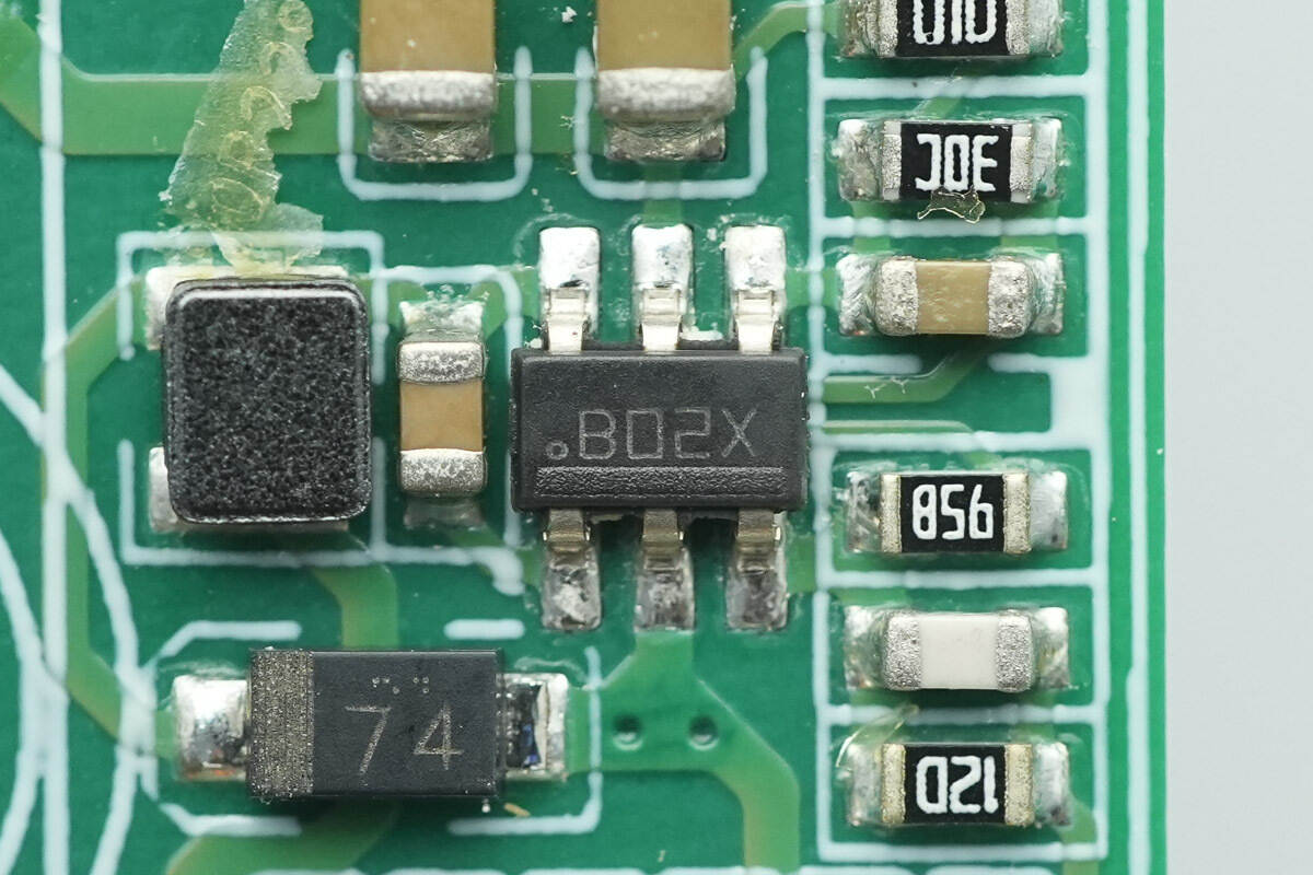
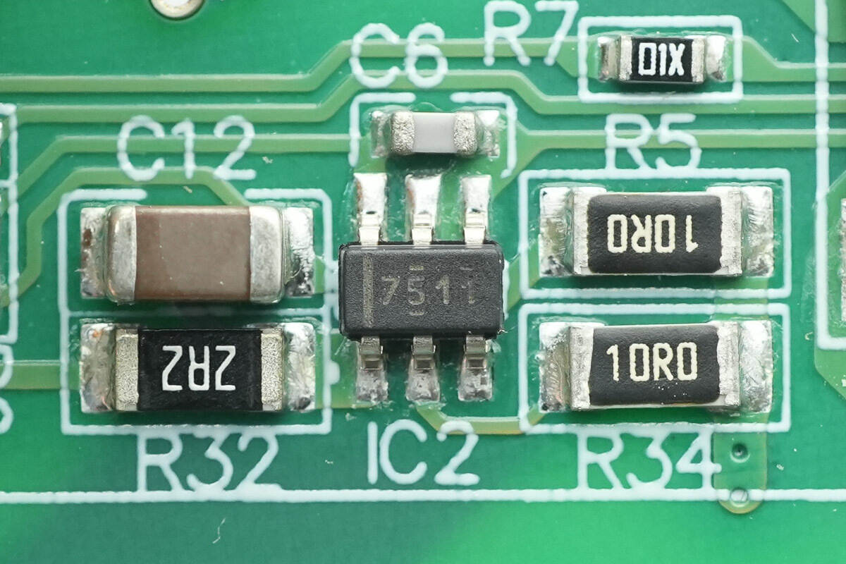
The buck converter chip is from TI, marked B02X, model LMR14006. It supports a 40 V input voltage, delivers 600 mA output current, features an integrated MOSFET, and comes in a TSOT-6L package.
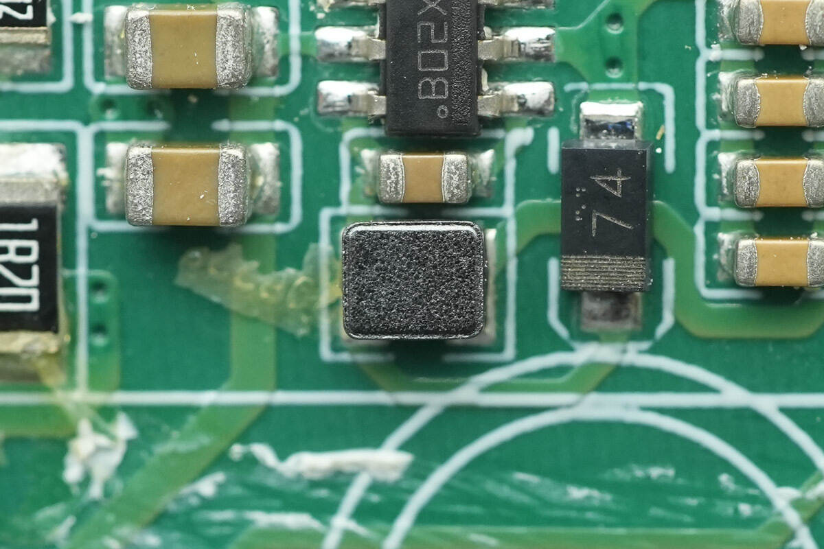
Close-up of the SMD inductor.
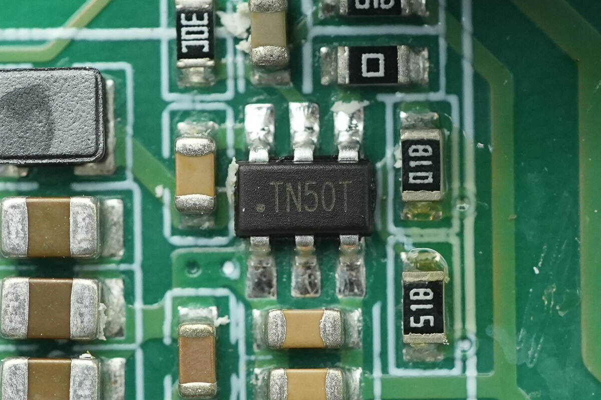
Close-up of the chip marked TN50T.
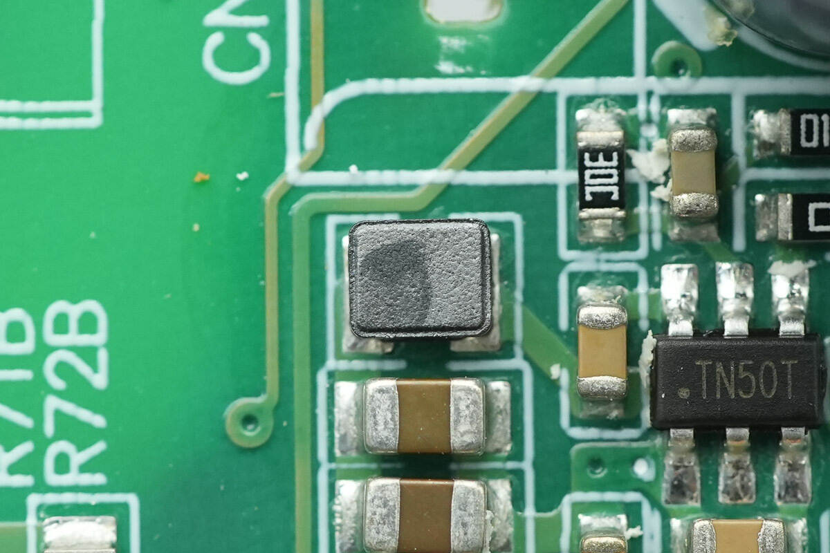
Close-up of the SMD inductor.
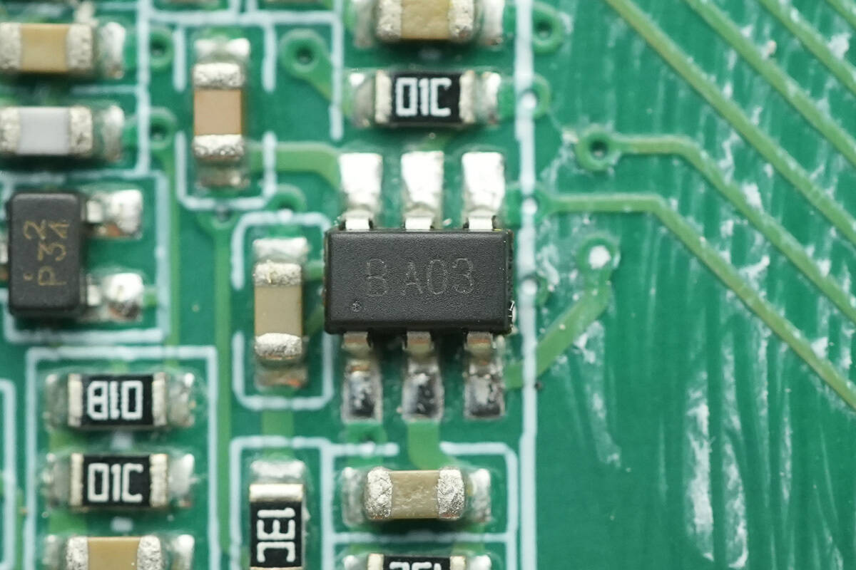
Close-up of the chip marked BA03.
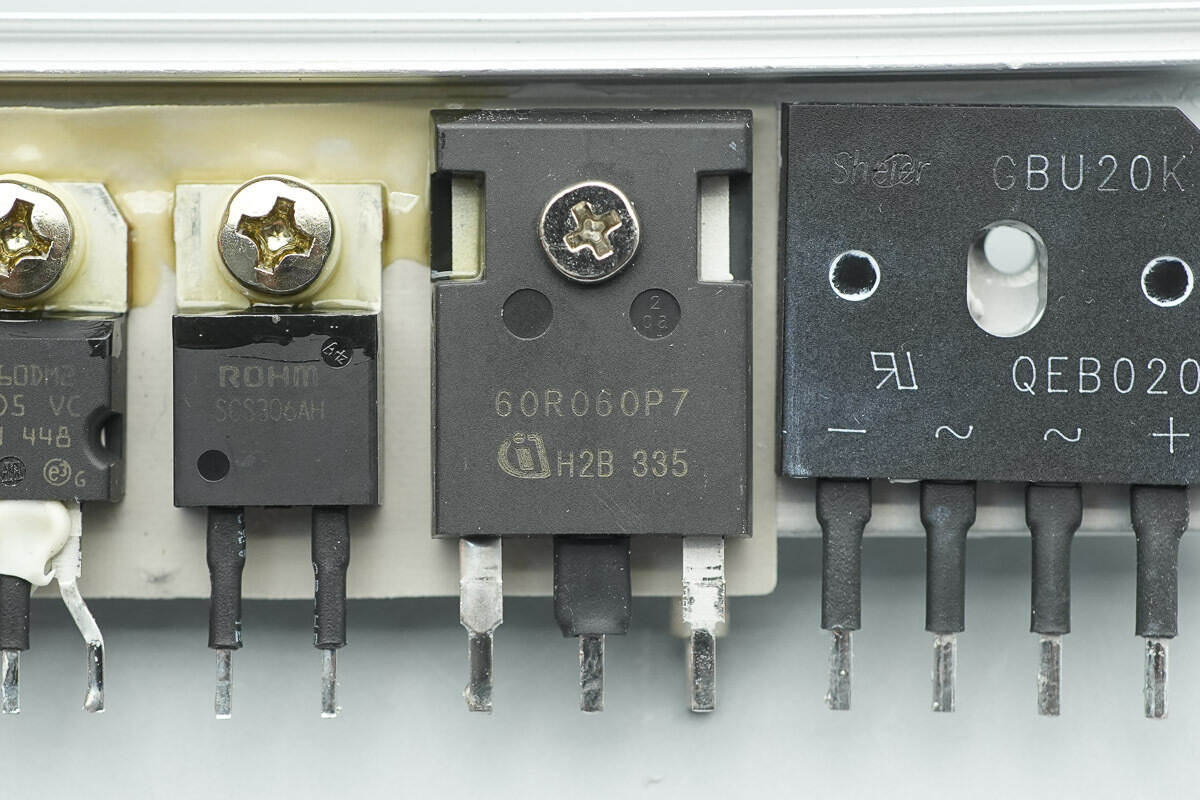
The PFC MOSFET is from Infineon, model IPW60R060P7. It belongs to the CoolMOS P7 series, is an NMOS, rated at 650 V, with an on-resistance of 60 mΩ, and comes in a TO-247-3 package.
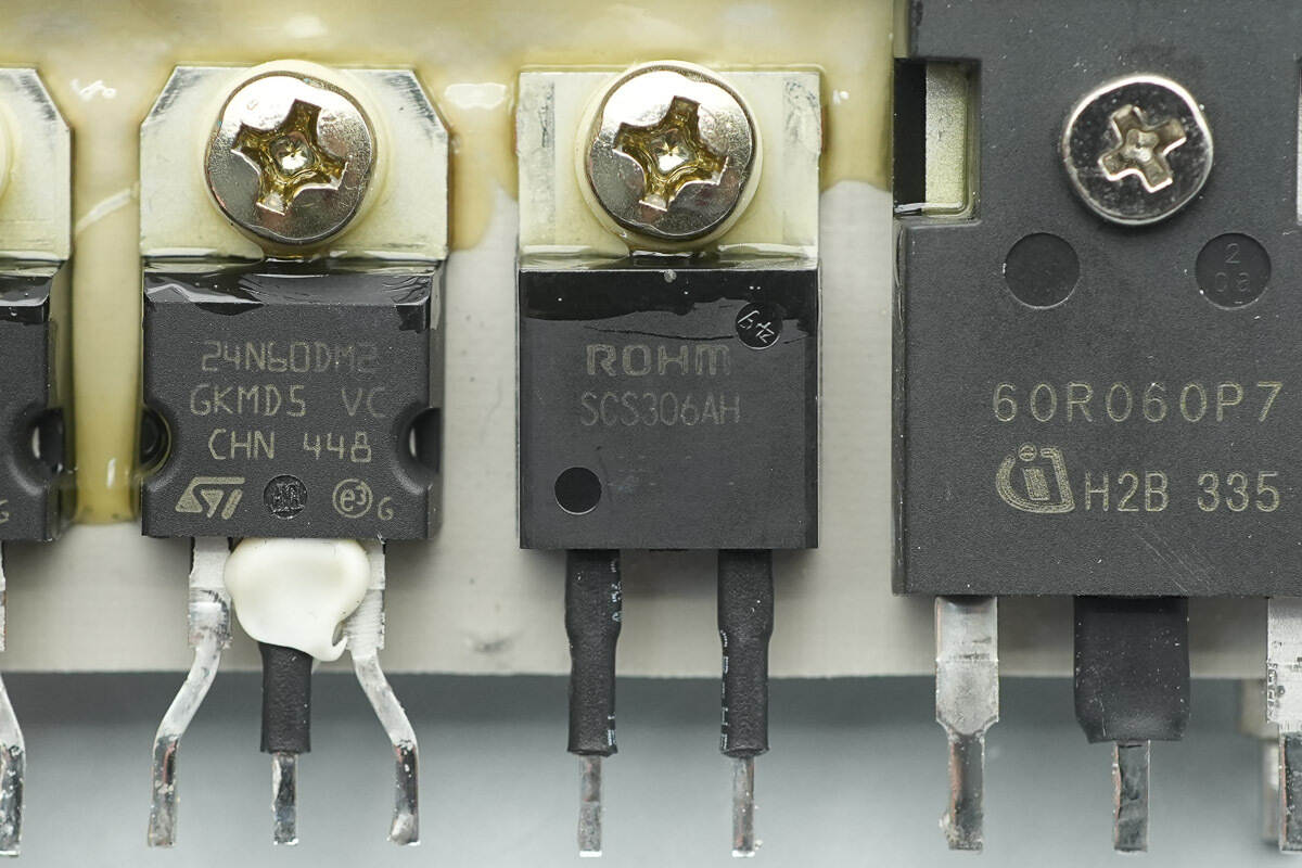
The PFC rectifier is from ROHM, model SCS306AH. It is a SiC Schottky diode, rated 650 V/6 A, and comes in a TO-220ACP package.
The PFC MOSFET driver is from TI, model UCC27511. It is a single-channel high-speed driver, featuring a 4 A peak source current and 8 A peak sink current, and comes in a SOT-23 package.
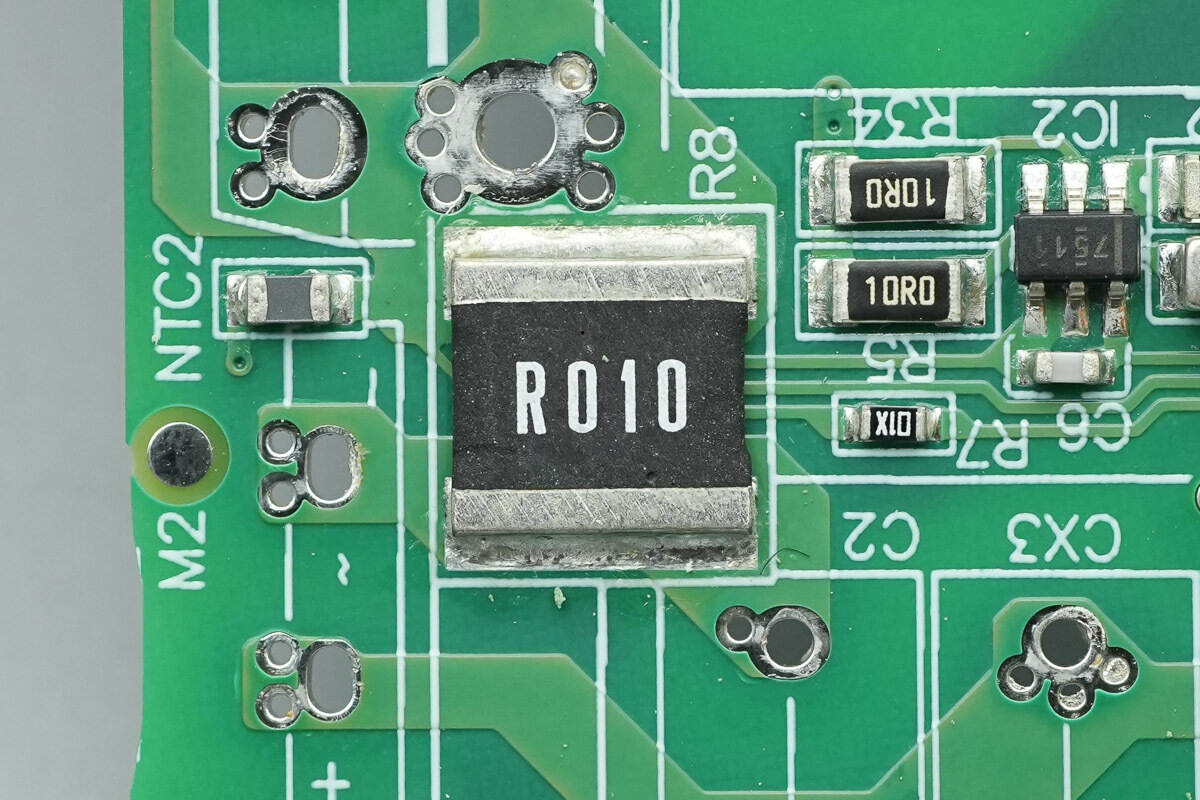
A 10 mΩ sense resistor is used to monitor the current of the PFC MOSFET.
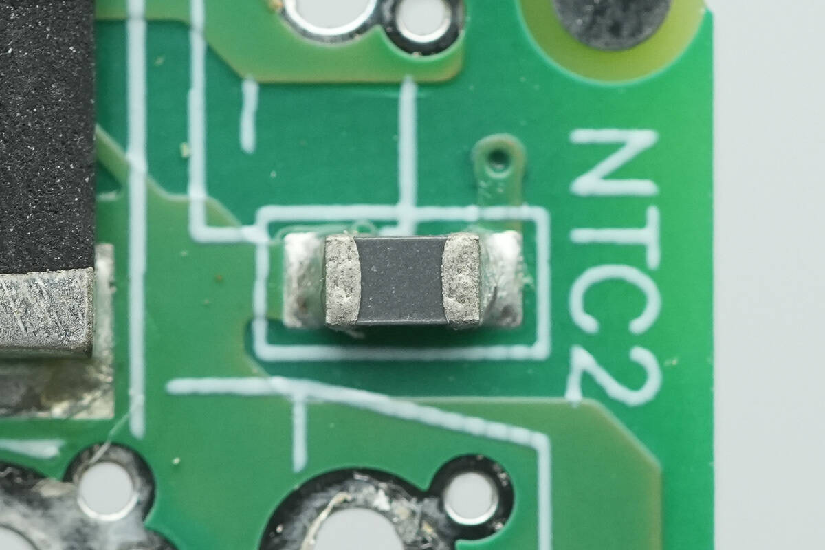
An NTC thermistor is used to monitor the temperature of the PFC MOSFET.
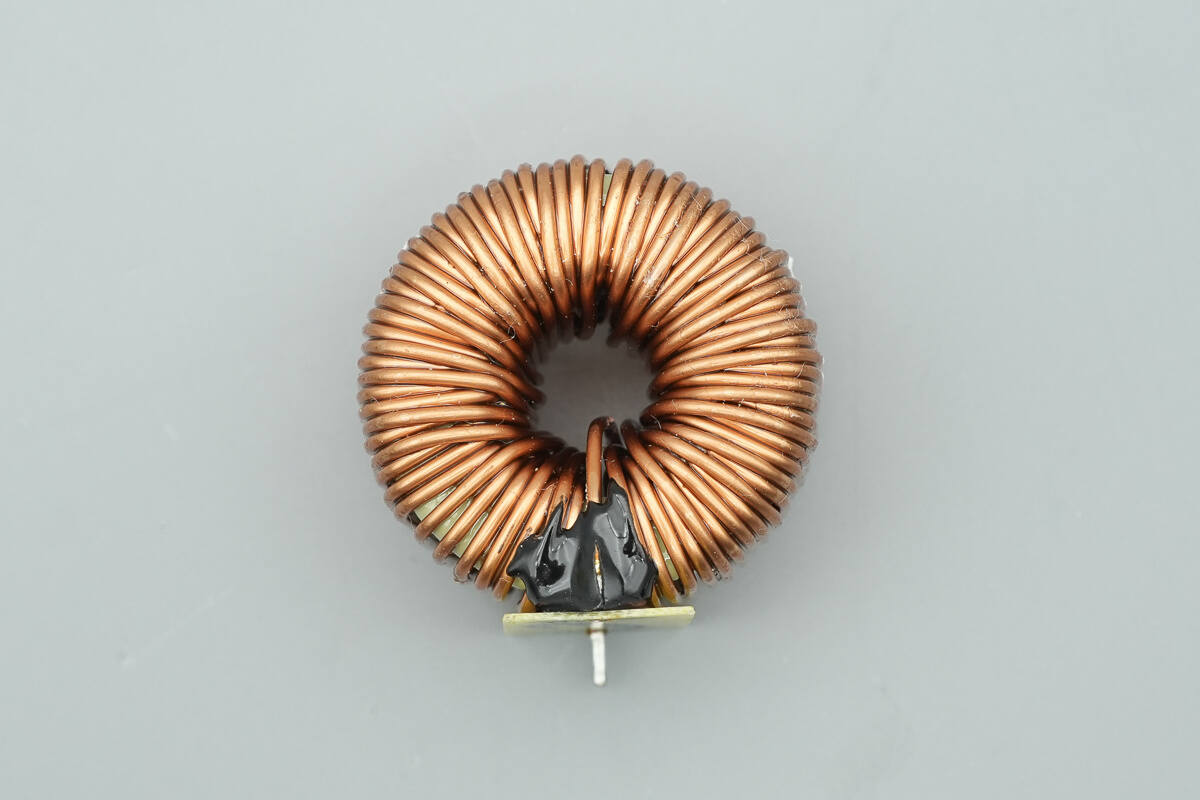
The PFC boost inductor is wound with enameled wire and features a bakelite board for insulation at the base.
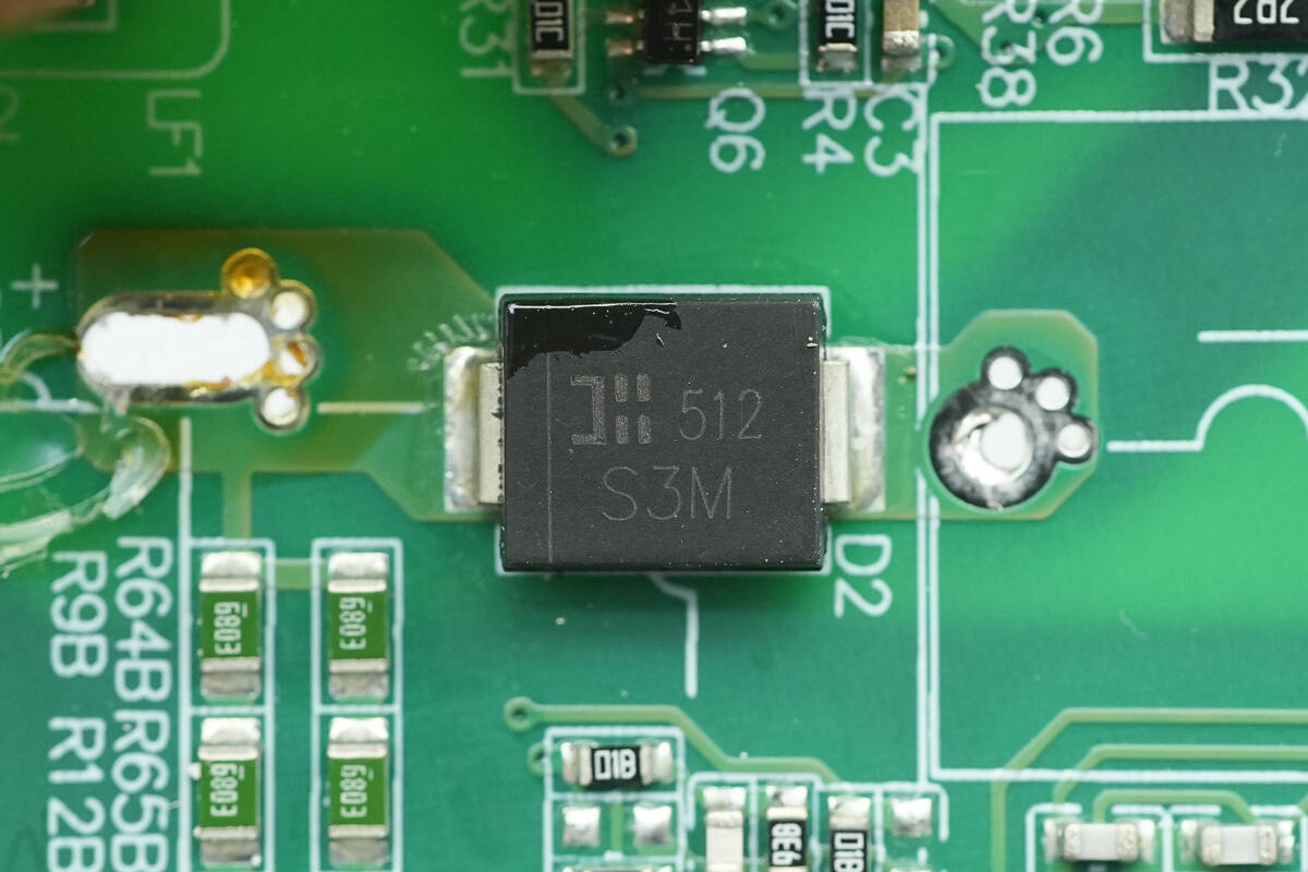
The bypass diode is from DIODES, model S3M, rated 1000 V/3 A, and comes in an SMC package.
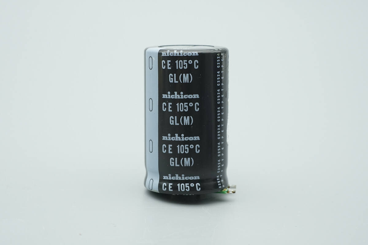
The high-voltage filter capacitor is from Nichicon, part of the GL series of compact electrolytic capacitors, rated for 105 °C operation.
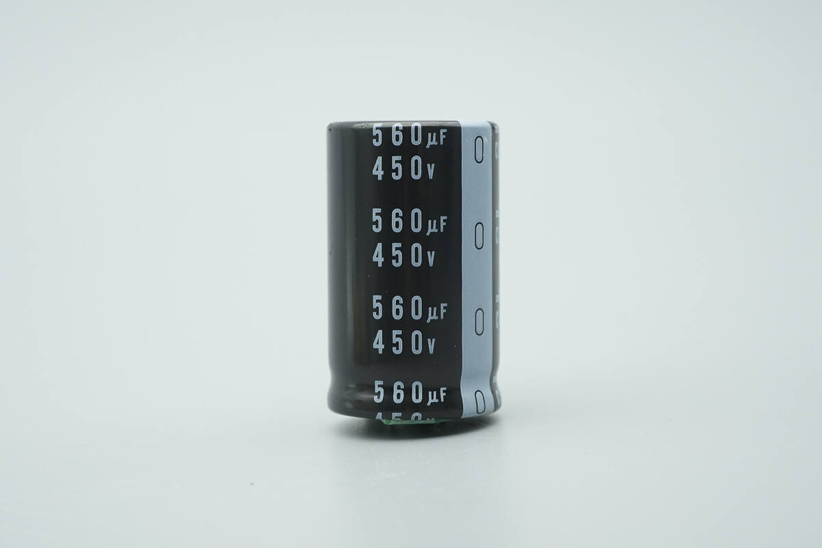
It is rated at 560 μF, 450 V.
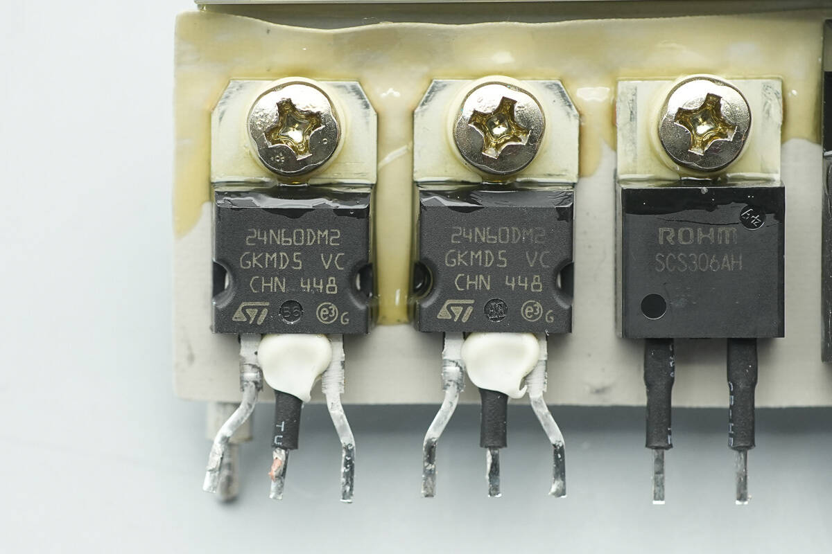
The LLC MOSFETs are from STMicroelectronics, model STP24N60M2. They are NMOS devices, rated 600 V, with an on-resistance of 190 mΩ, and come in a TO-220 package.
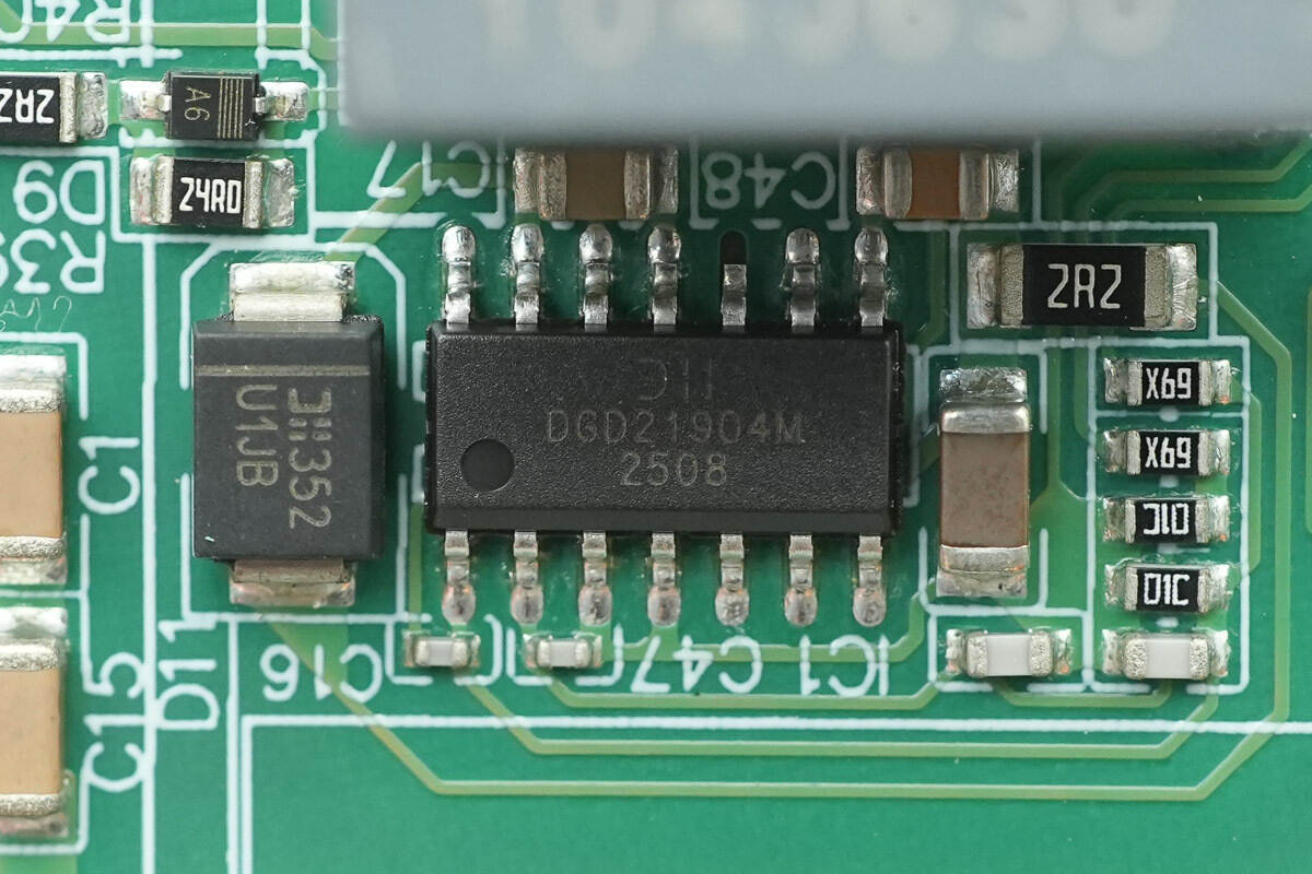
The driver is from DIODES, model DGD21904M. It is a half-bridge driver, rated 600 V, suitable for MOSFET and IGBT applications, with a 4.5 A drive current, and comes in an SO-14 package.
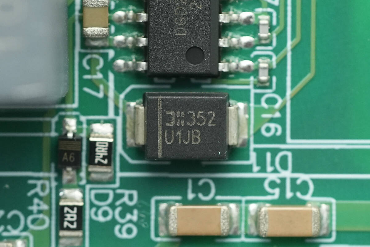
The fast-recovery diode is from DIODES, marked U1JB, model MURS160, rated 600 V/1 A, and comes in an SMB package.
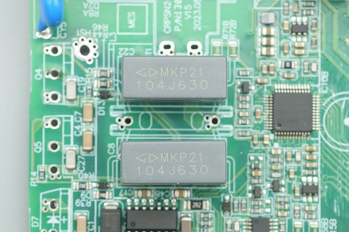
The resonant capacitors are from Faratronic, rated 0.1 μF, 630 V.
The resonant inductor is wound with Litz wire.
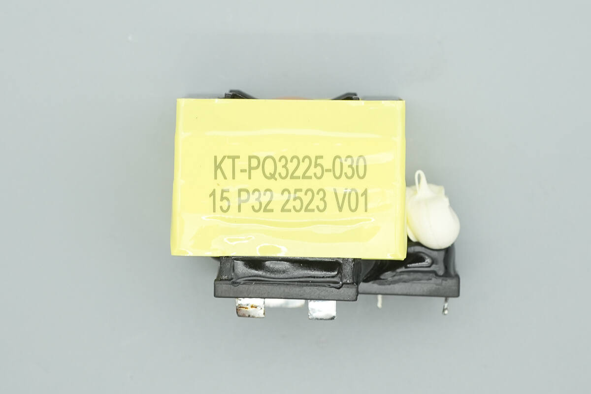
The LLC transformer is equipped with a current transformer.
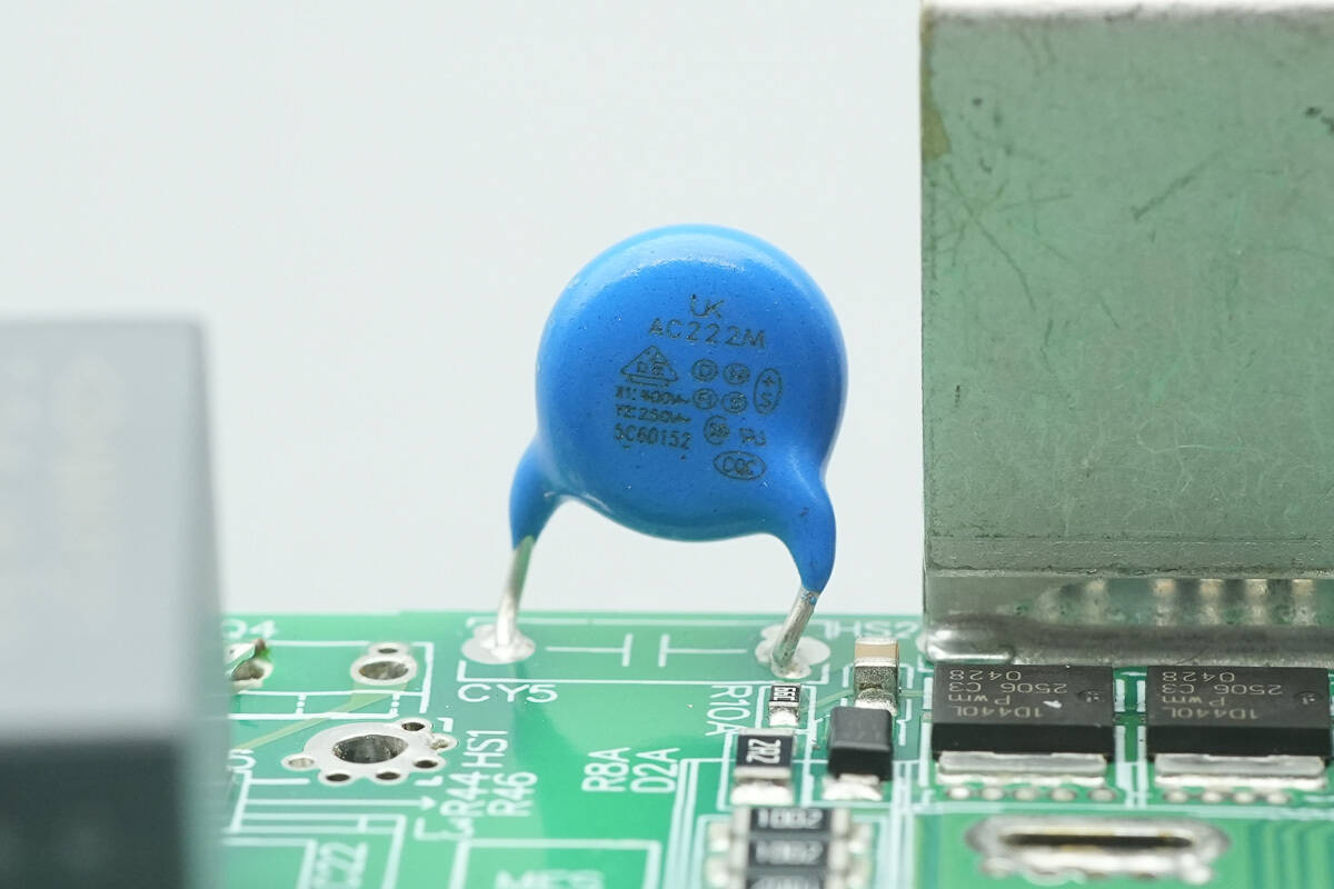
The blue Y-capacitor is from Walsin, part number AC222M.
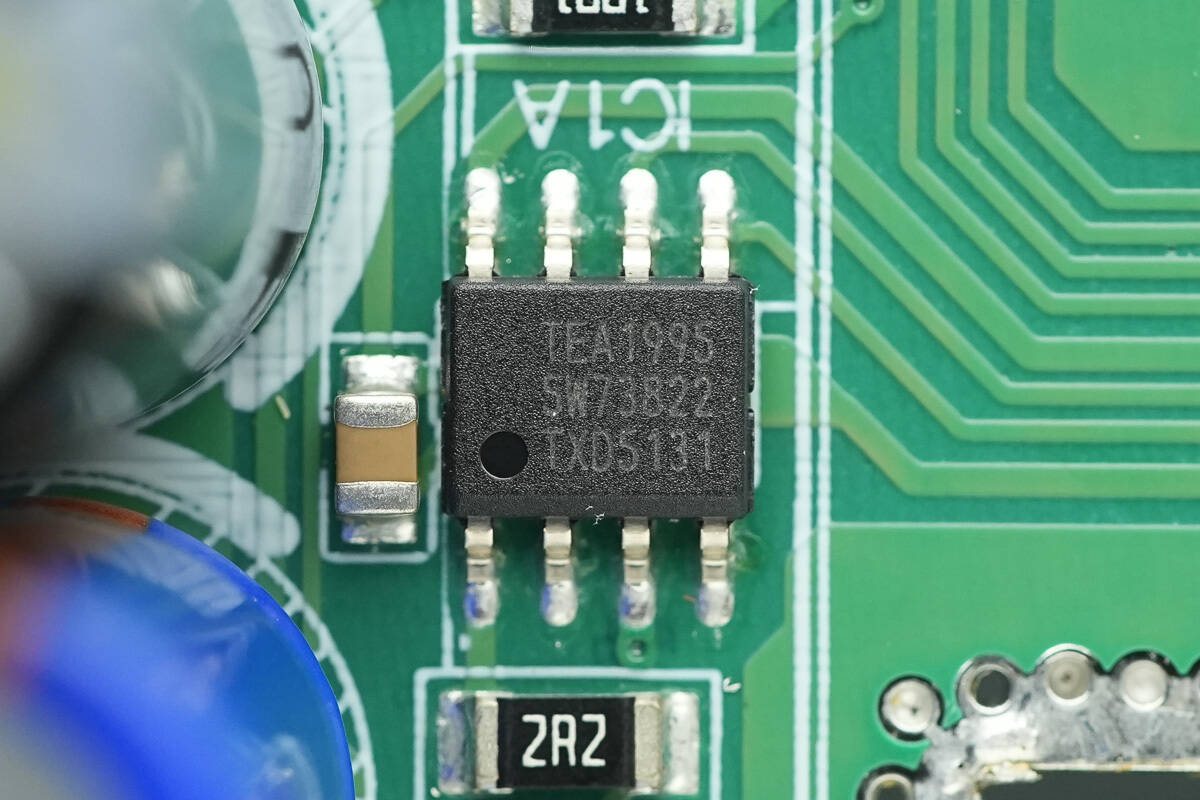
The synchronous rectifier controller is from NXP, model TEA1995. It features two independent synchronous rectifier drivers for LLC architecture switching power supplies, requires minimal external components, supports a 38 V operating voltage, and comes in an SO-8 package.
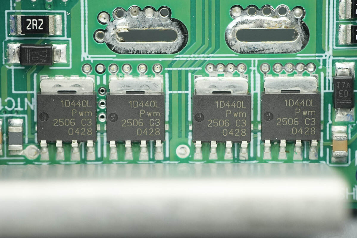
The synchronous rectifiers are from Nexperia, marked 1D440L, model PSMN1R4-40YLD. They are NMOS devices, rated 40 V, with an on-resistance of 1.12 mΩ, housed in an LFPAK56 package, with two units connected in parallel.
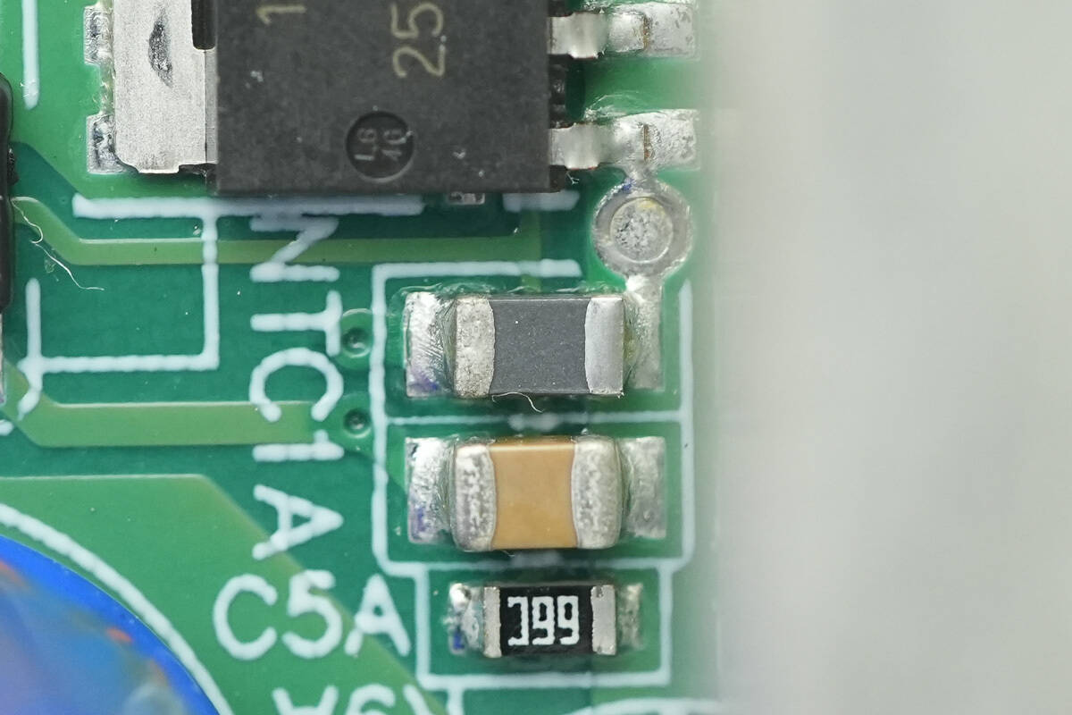
An NTC thermistor is installed on the inner side of the synchronous rectifiers to monitor temperature.
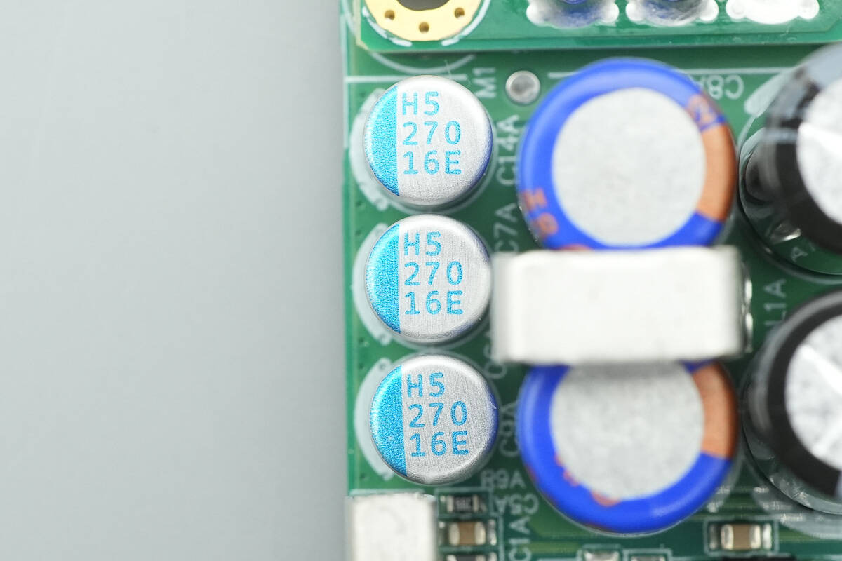
The filter capacitors are from Lelon, part of the ORE series of polymer solid aluminum electrolytic capacitors, rated 270 μF, 16 V.
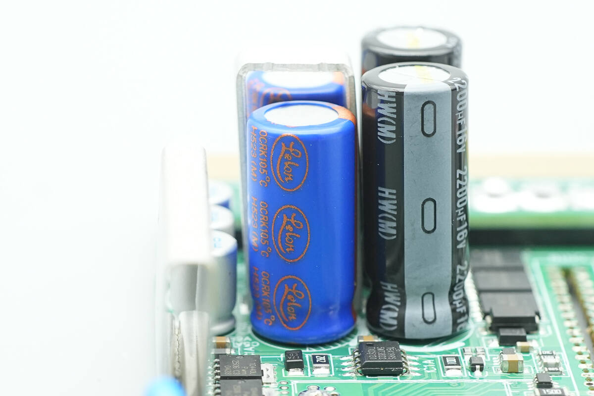
The filter capacitors are from Lelon, part of the OCRK series of solid capacitors, rated for 5,000 hours of service life and 105 °C operating temperature.
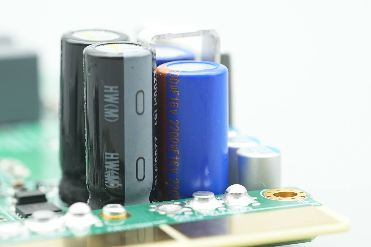
They are rated 2200 μF, 16 V.
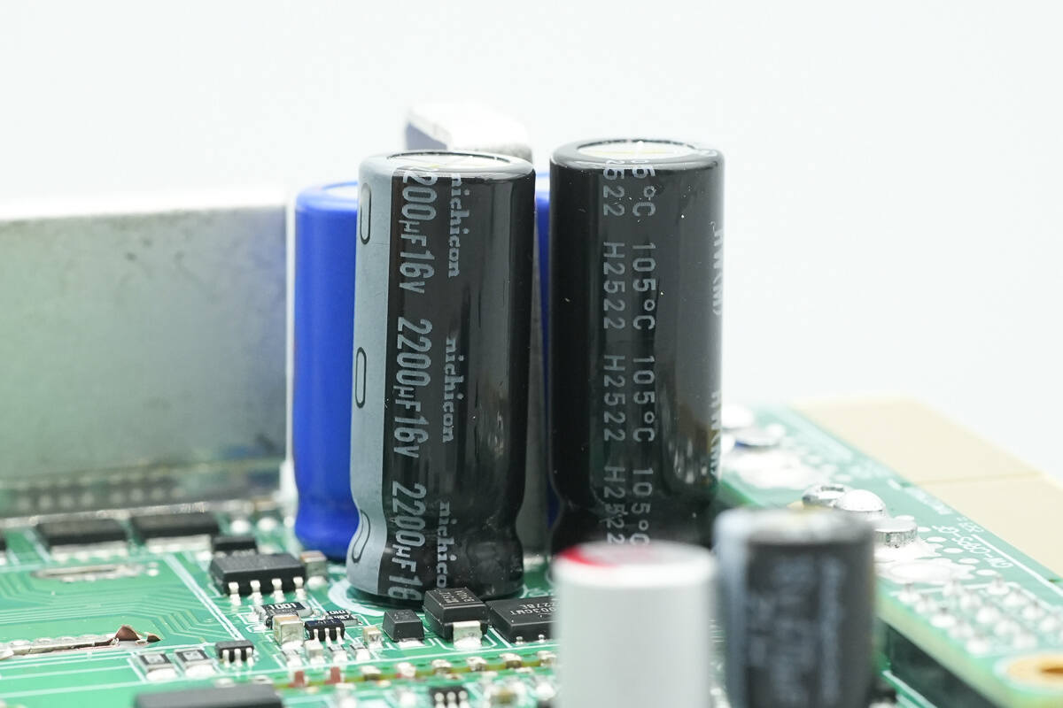
The filter capacitors are from Nichicon, part of the UHW series of long-life, low-impedance electrolytic capacitors, rated 2200 μF, 16 V, and rated for 105 °C operation.
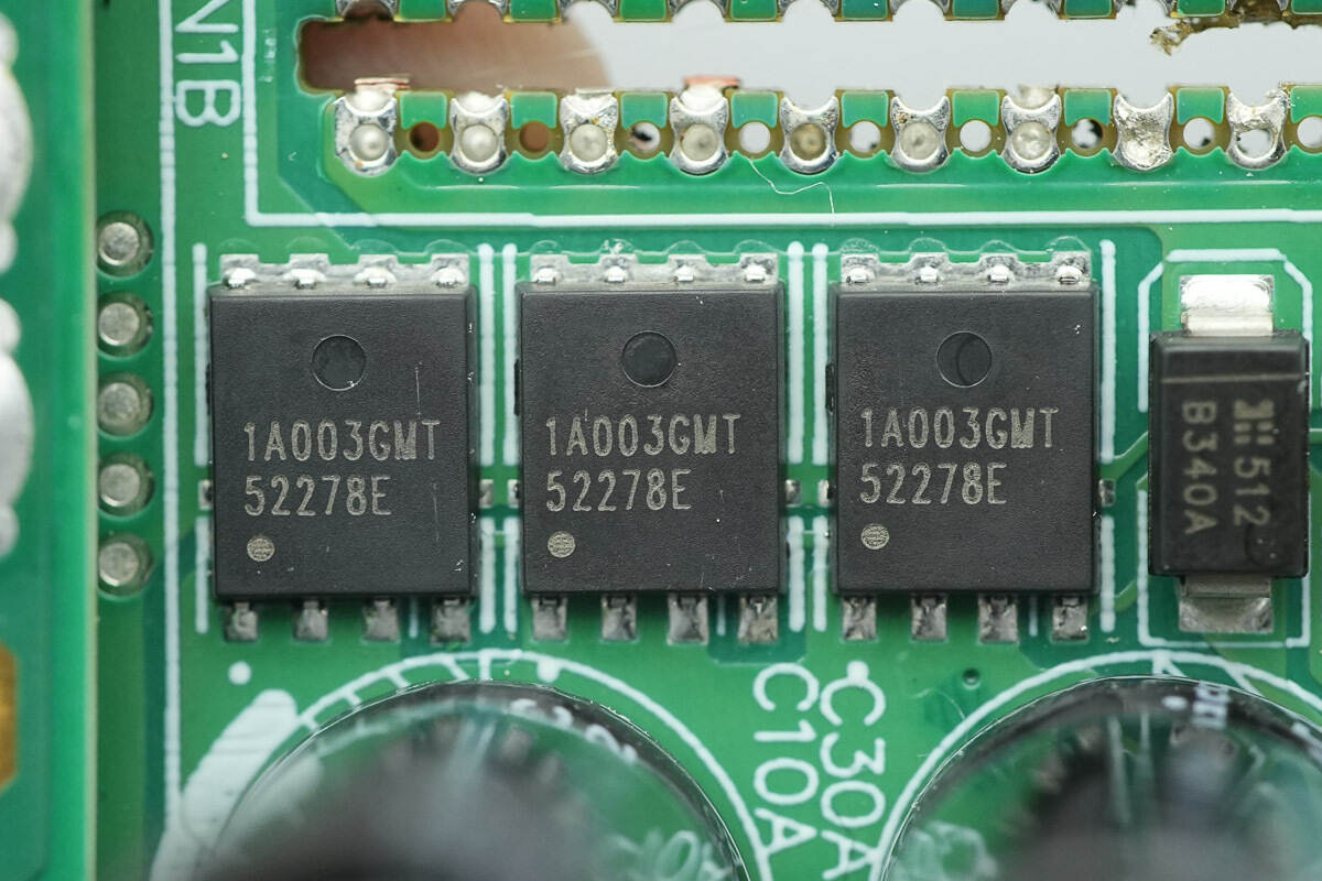
The output VBUS MOSFETs are from APEC, model AP1A003GMT. They are NMOS devices, rated 30 V, with an on-resistance of 0.99 mΩ, and come in a PMPAK 5×6 package.
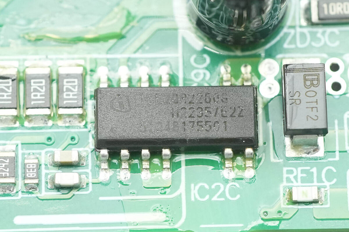
The standby power supply chip is from Infineon, model ICE2QR2280G. It integrates an 800 V MOSFET, supports 30 W output power over a wide input voltage range, and comes in a DSO-12 package.
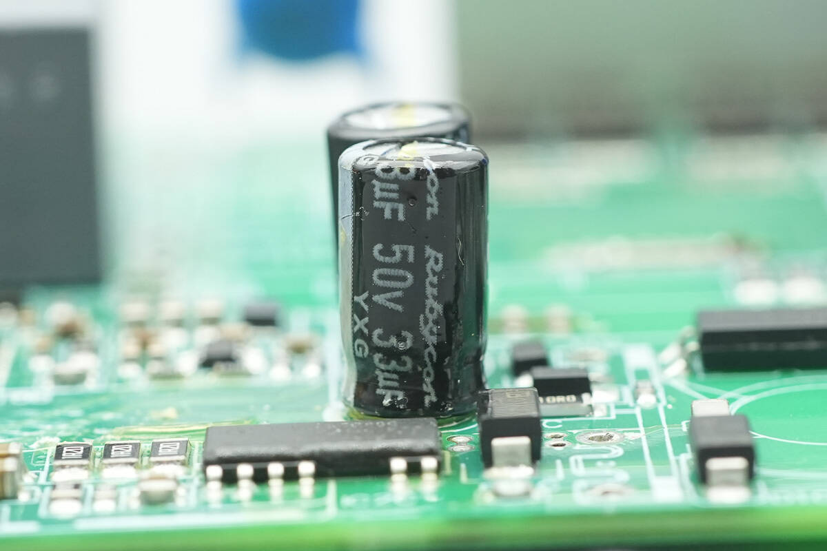
The filter capacitors are from Rubycon, rated 33 μF, 50 V.
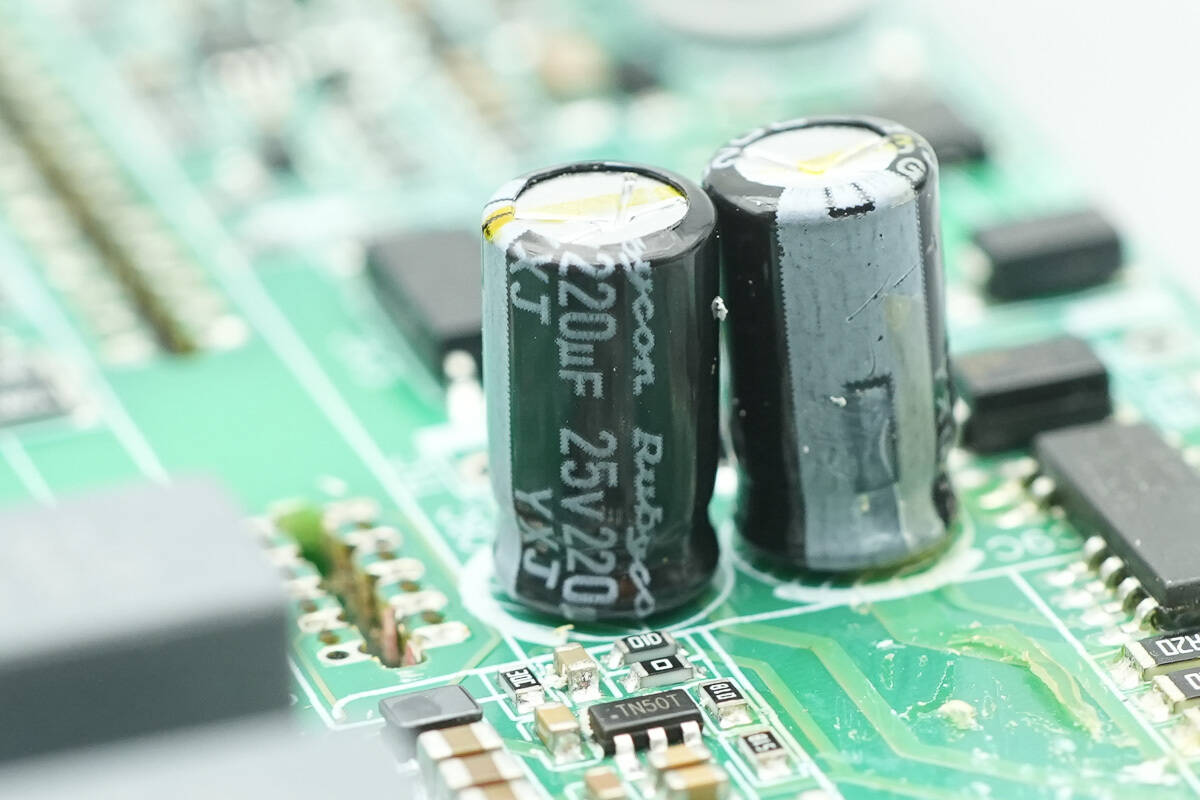
They are rated 220 μF, 25 V.
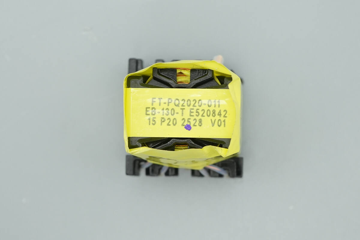
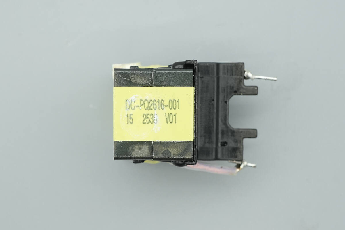
The standby power transformer is tightly wrapped with insulating tape.
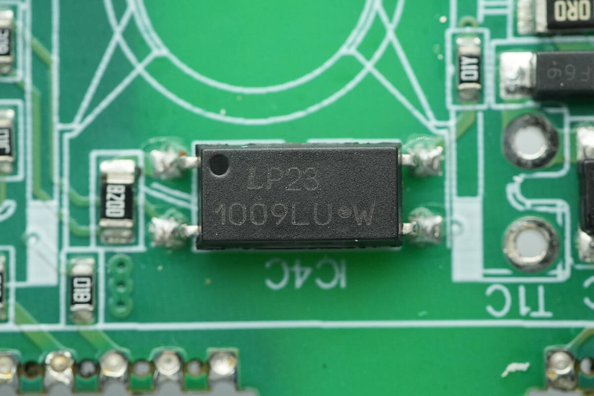
The LITEON LTV-1009 optocoupler is used for output power feedback.
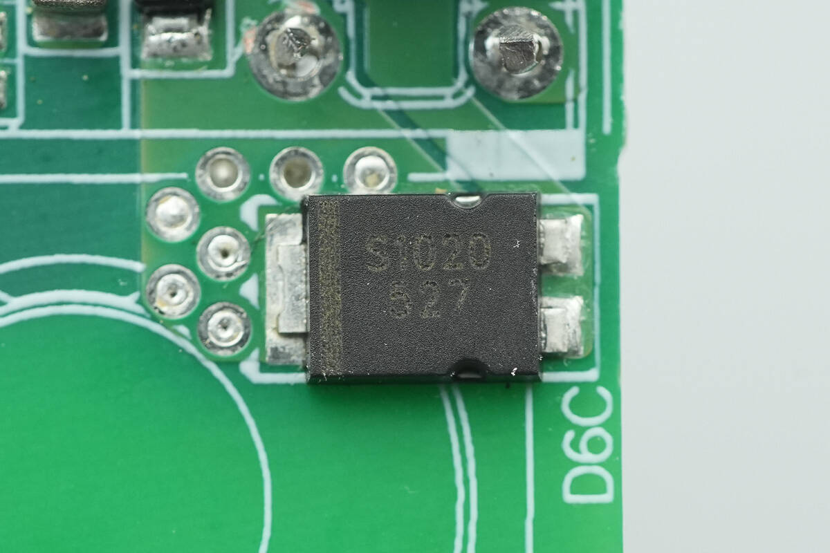
The standby power rectifier is marked S1020 and comes in a TO-277 package.
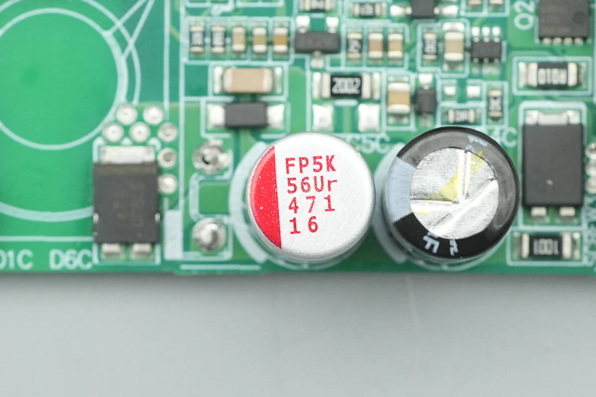
The filter capacitor is from Nichicon, part of the RL8 series of conductive polymer aluminum solid electrolytic capacitors, rated 470 μF, 16 V.
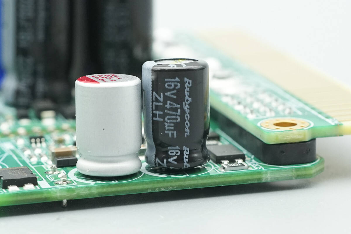
The filter capacitor is from Rubycon, part of the ZLH series of long-life electrolytic capacitors, rated 470 μF, 16 V.
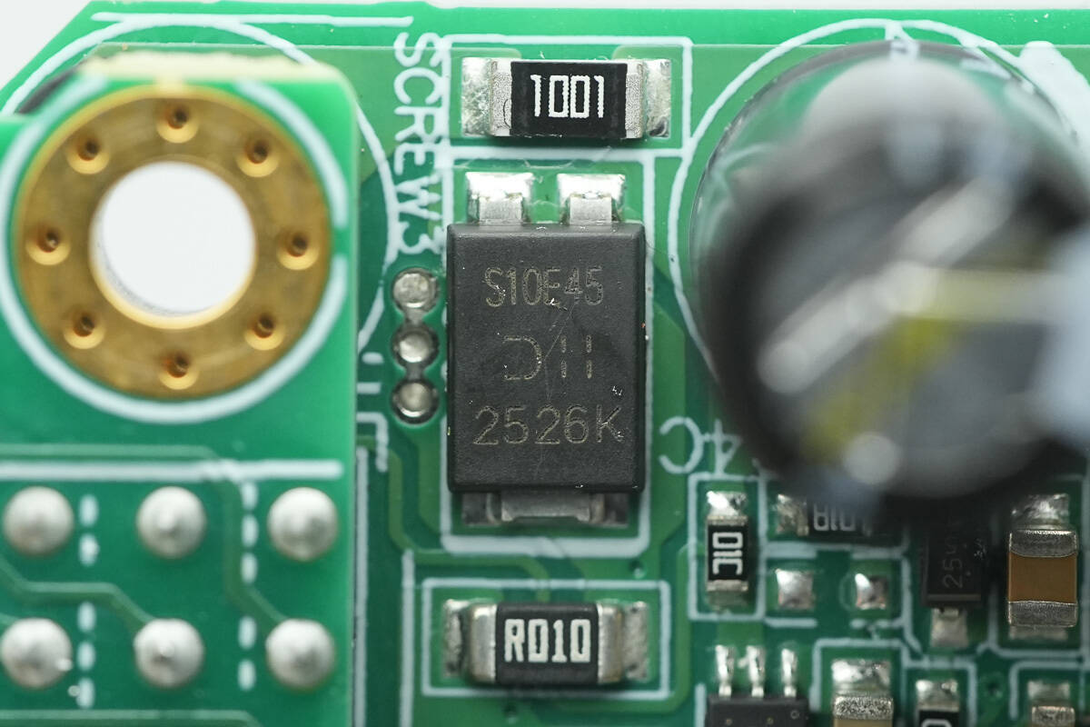
The diode is from Diodes, marked S10E45, with the model SBR10E45P5. It is rated at 45 V and 10 A, and is packaged in Power DI5.
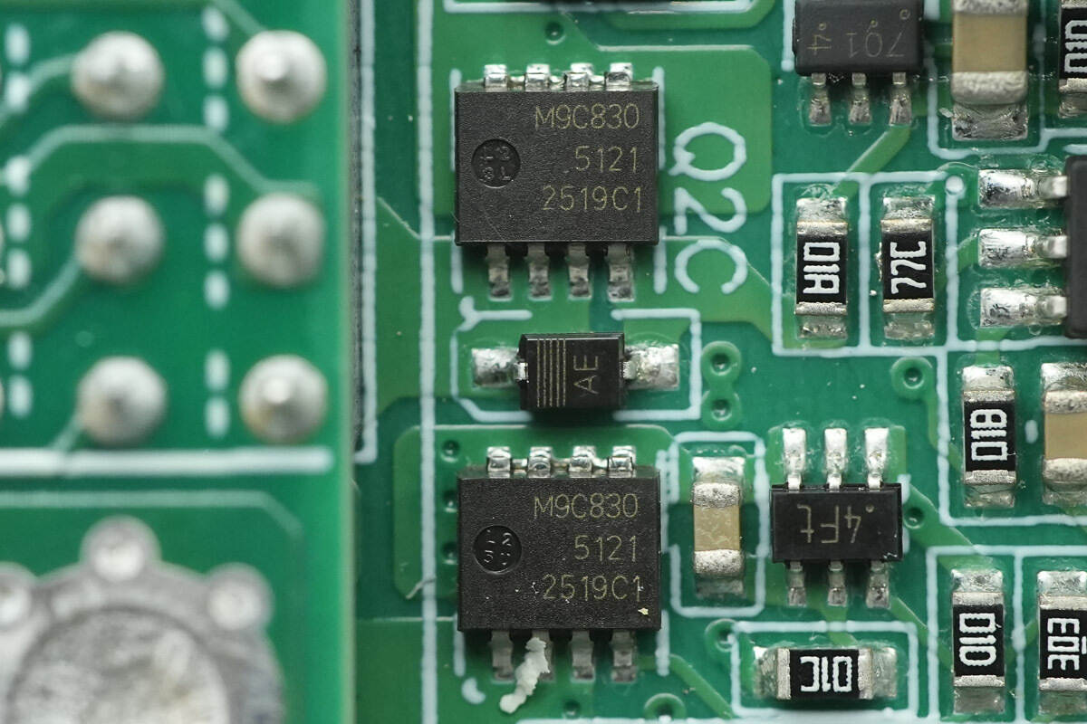
The MOSFETs used for power control are from Nexperia, marked M9C830, with the model PSMN9R8-30MLC. These are NMOS devices rated at 30 V, with an on-resistance of 9.8 mΩ, and are packaged in LFPAK33.
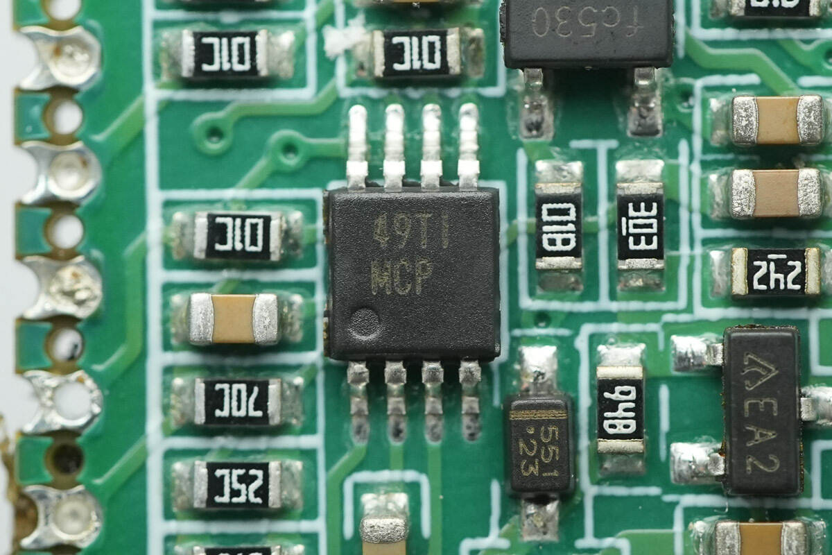
The voltage comparator is from TI, marked MCP, with the model LM293. It is an industrial-grade dual differential comparator, packaged in VSSOP-8.
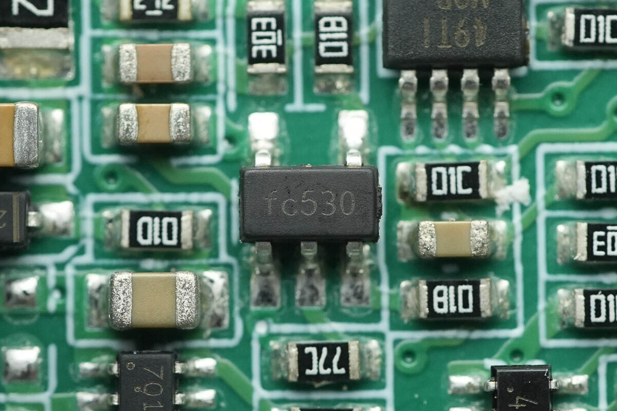
Close-up of the chip marked FC530.
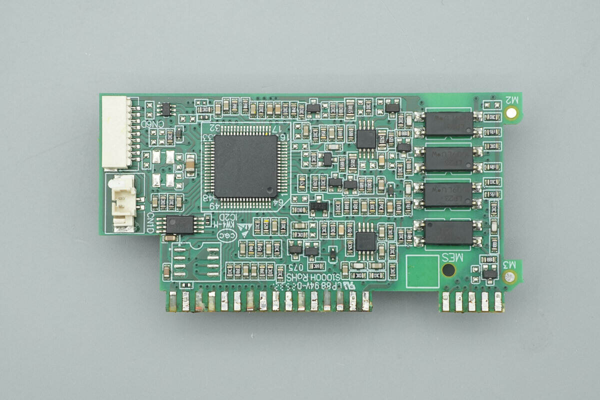
One side of the control PCB houses the MCU, memory, operational amplifiers, and optocouplers.
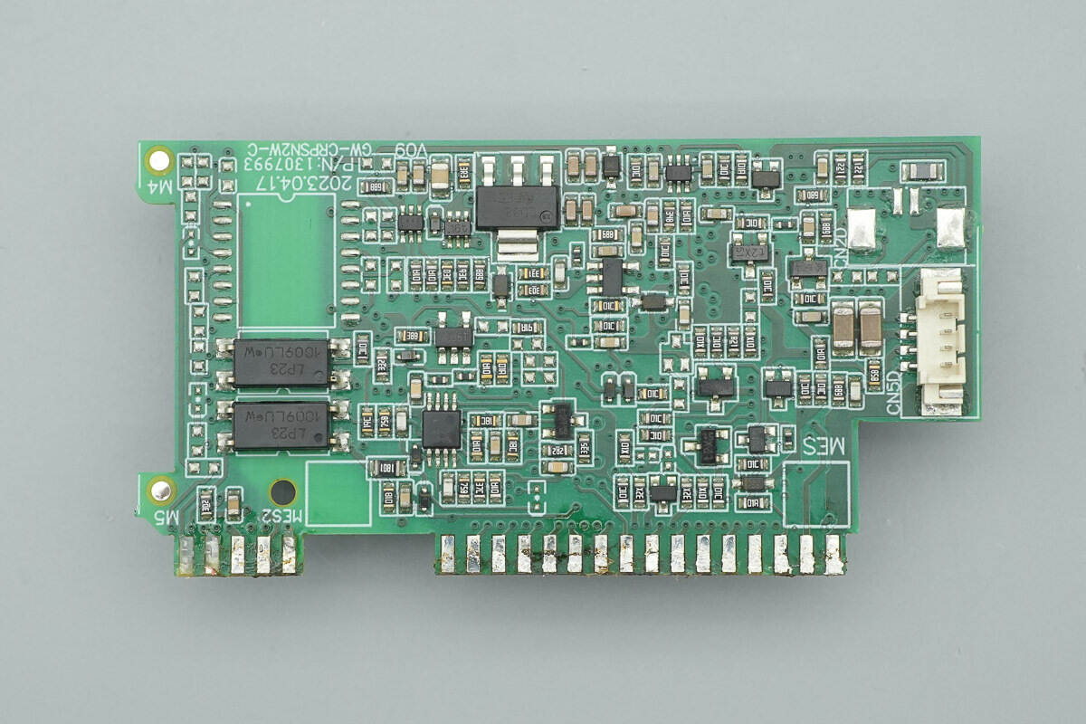
The other side is populated with a voltage regulator IC, an operational amplifier, and optocouplers, among other components.
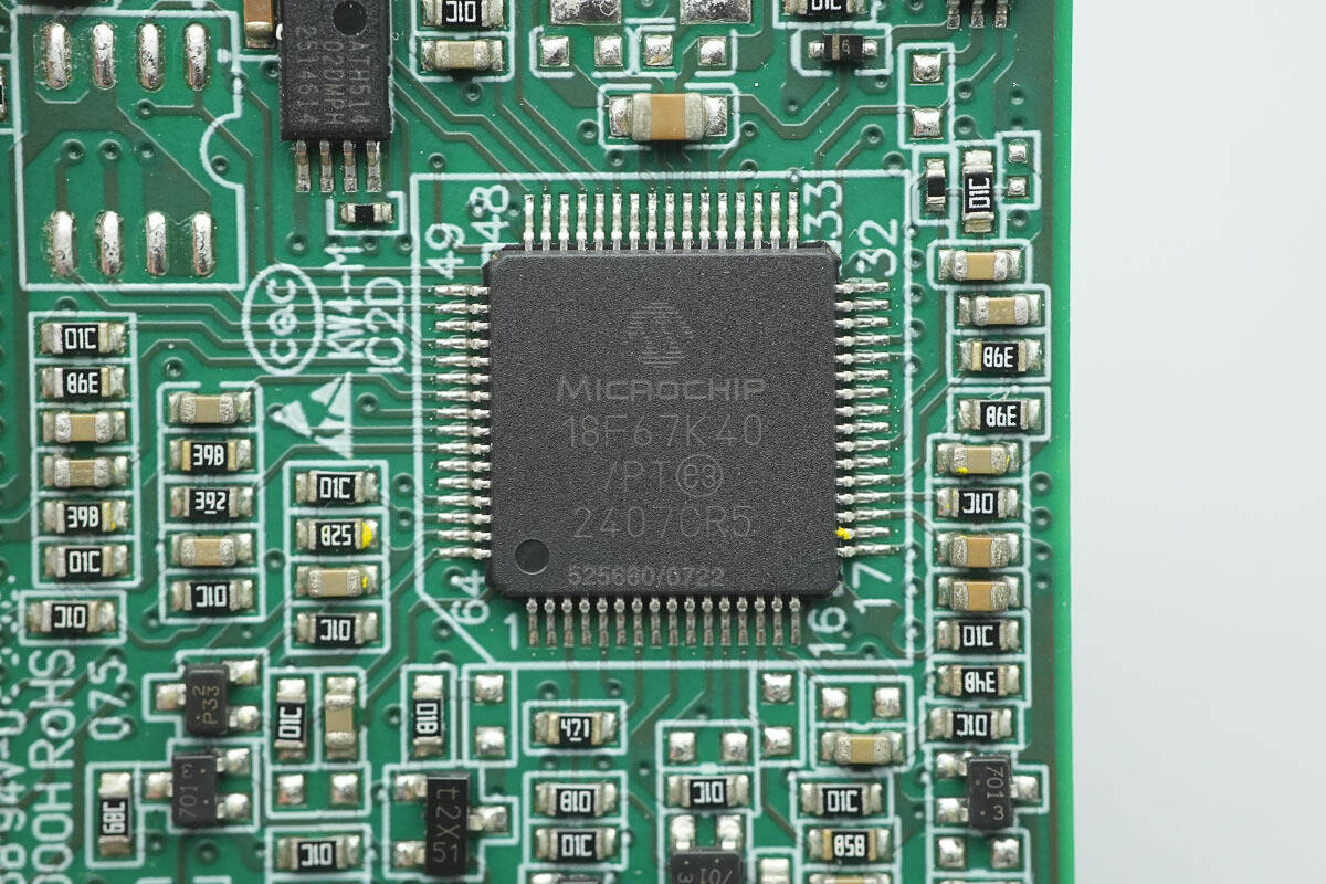
The MCU is from Microchip Technology, model PIC18F67K40. It integrates a PIC18 core, with 128 KB Flash, 3,562 B SRAM, and 1 KB EEPROM. The device features a 47-channel 10-bit ADC, five EUSART interfaces, and two I2C/SPI interfaces, and is packaged in a 64-pin TQFP.
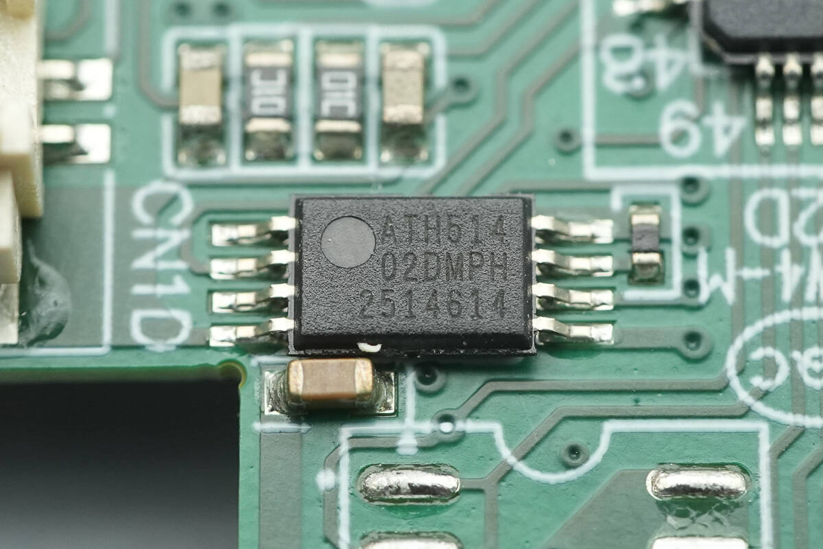
The memory is from Microchip Technology, marked 02DM, with the model AT24C02D. It has a capacity of 2 Kb, operates over a voltage range of 1.7–3.6 V, and is packaged in TSSOP-8.
The operational amplifier is the TLV2171 from TI.
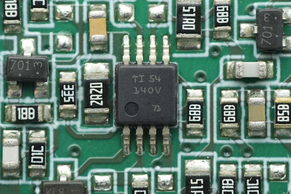
The other operational amplifier is of the same model.
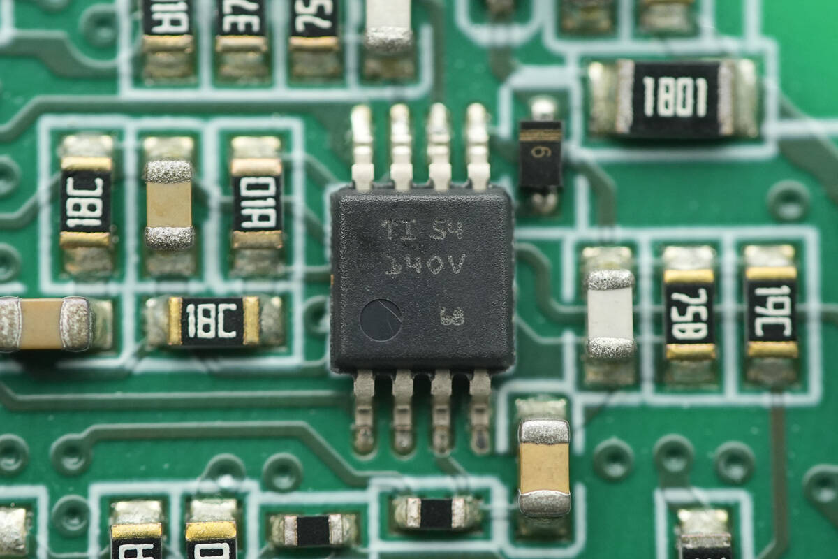
Another operational amplifier of the same model is also located on the opposite side.
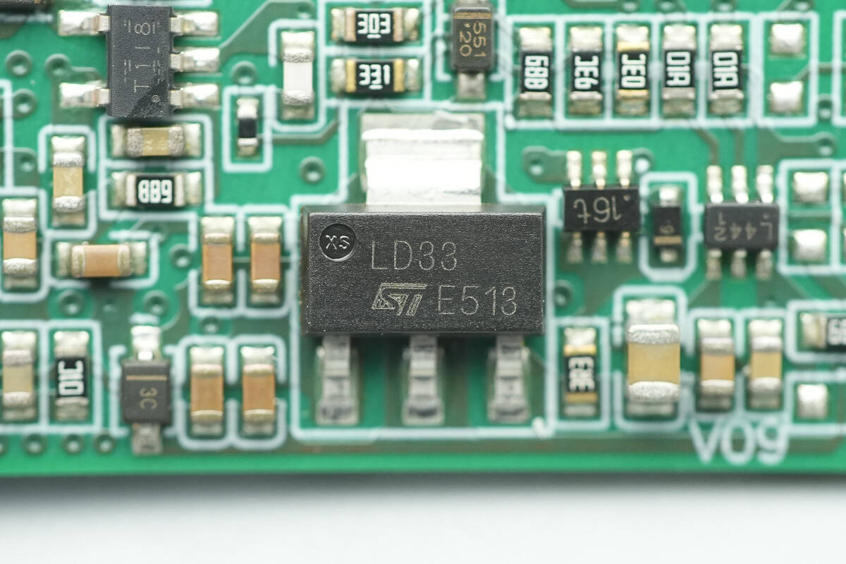
The voltage regulator is from STMicro, marked LD33, with the model LD1117S33TR. It supports up to 15 V input, provides a 3.3 V output, and delivers up to 800 mA, in an SOT-223 package.
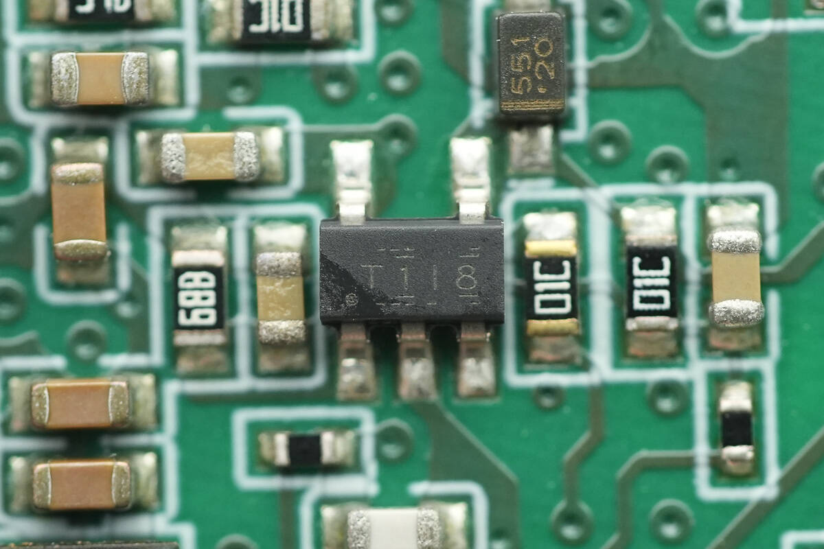
The voltage comparator is from TI, marked T1IB, with the model TL331. It is a high-voltage single-channel differential comparator, packaged in SOT-23-5.
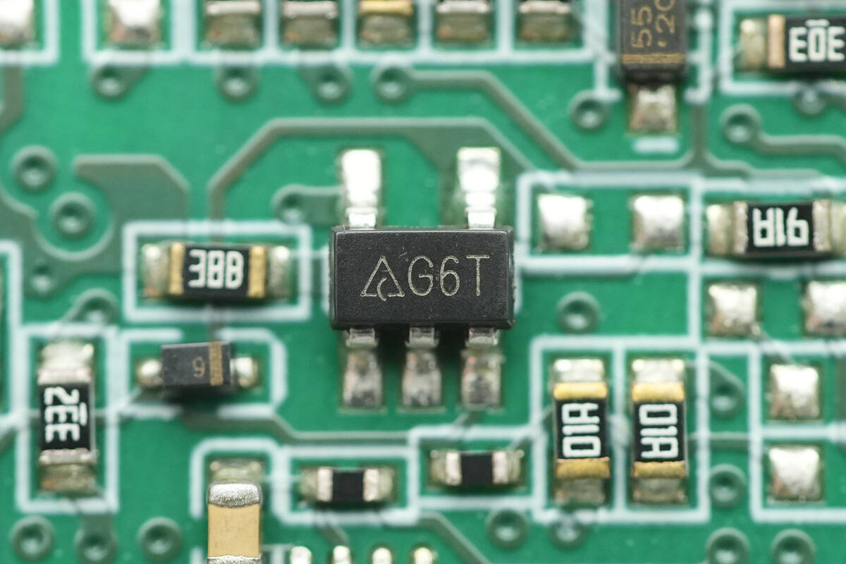
The single operational amplifier is from Diodes, marked G6T, with the model AS321. It is a low-power single op-amp, packaged in SOT-25.
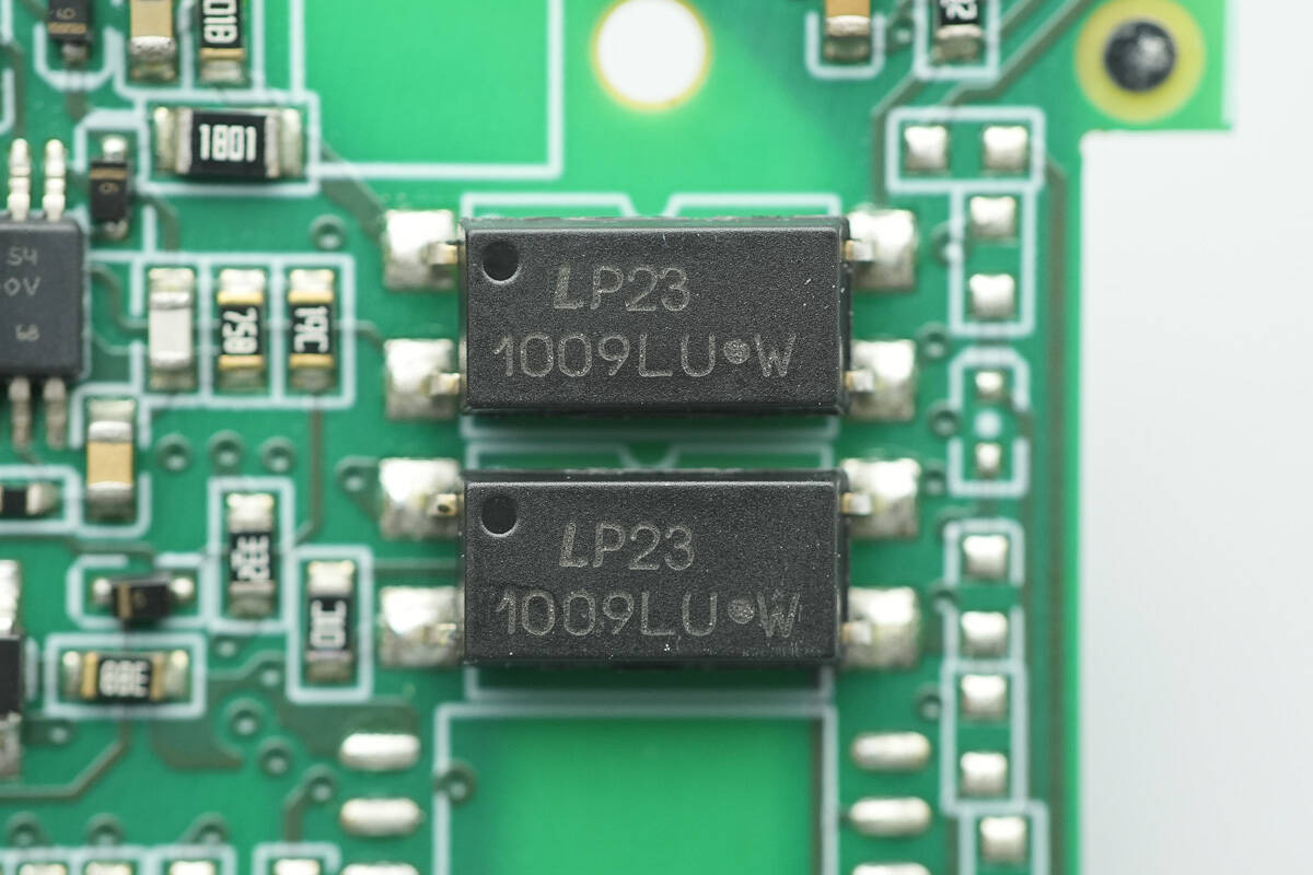
LITEON LTV1009 optocouplers are used for isolated communication.
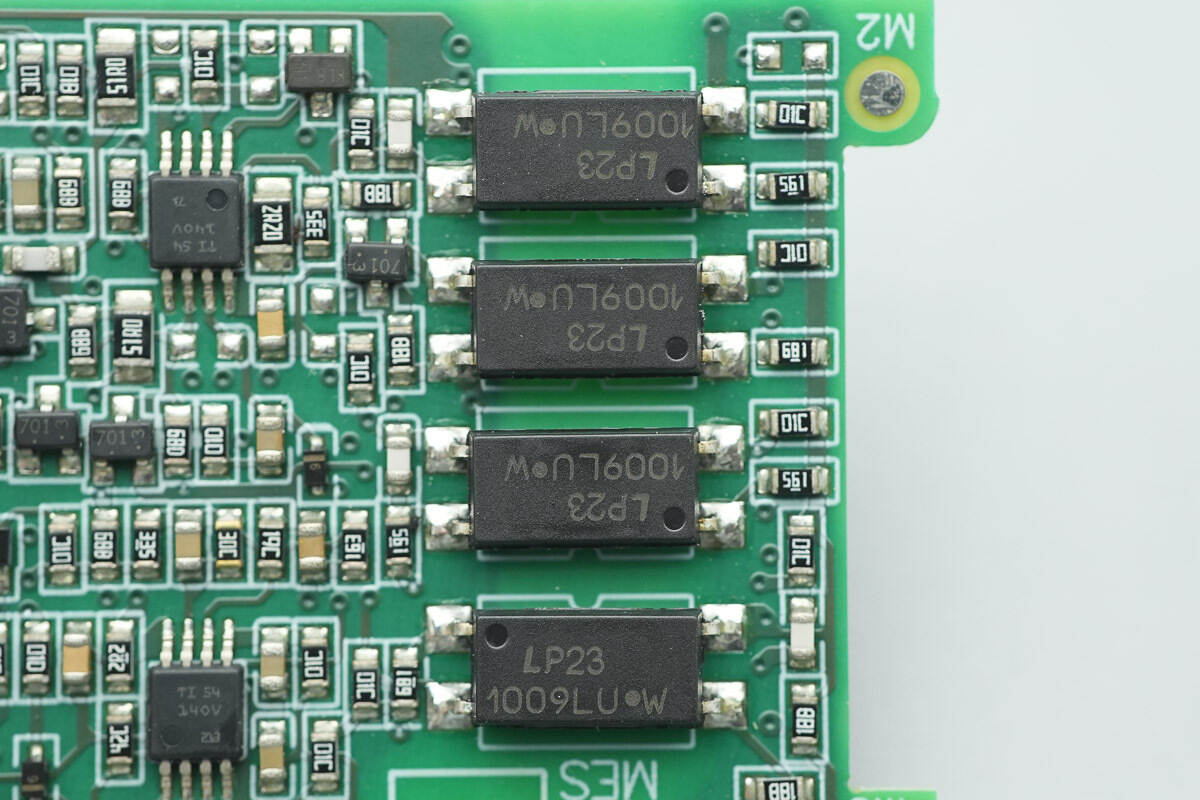
The other side features four optocouplers of the same model for isolation.
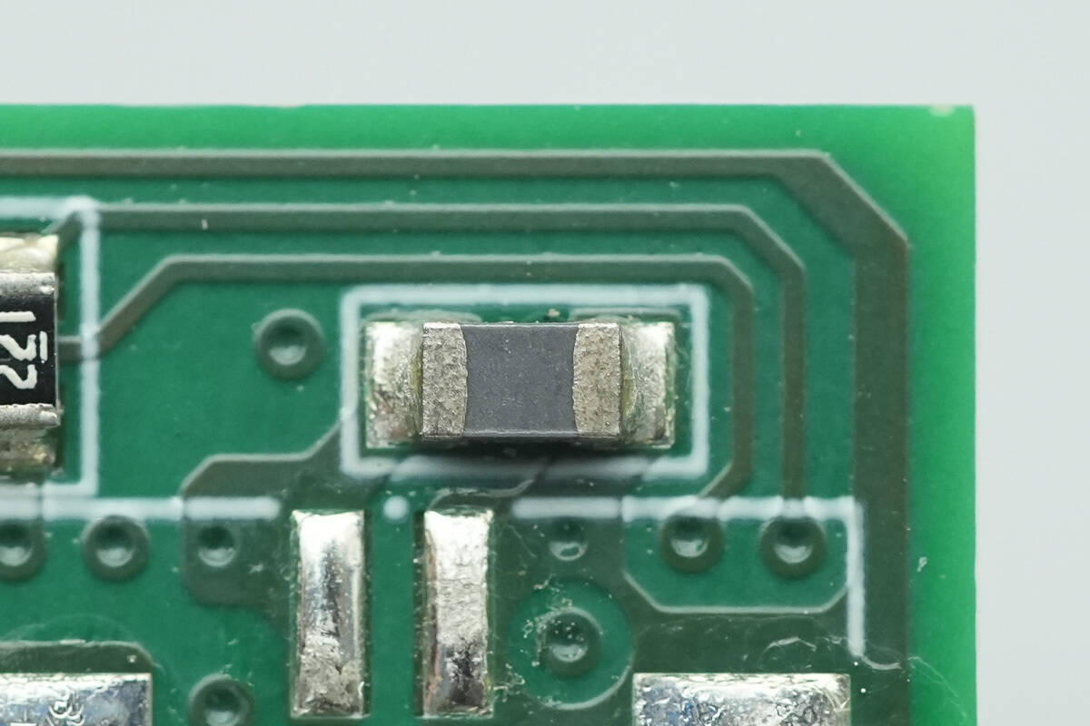
Close-up of the NTC thermistor used for temperature sensing.
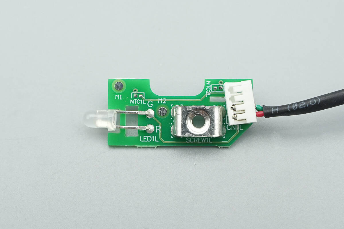
The indicator LED is soldered onto this small PCB.
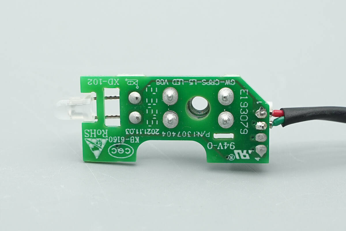
No components are populated on the backside.
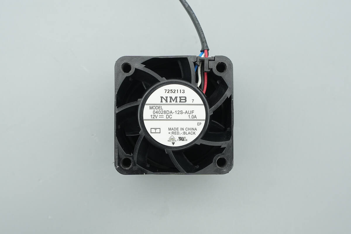
The cooling fan is from Minebea, model 04028DA-12S-AUF. It is rated at 12 V and 1 A, manufactured in China, and features stationary guide vanes.
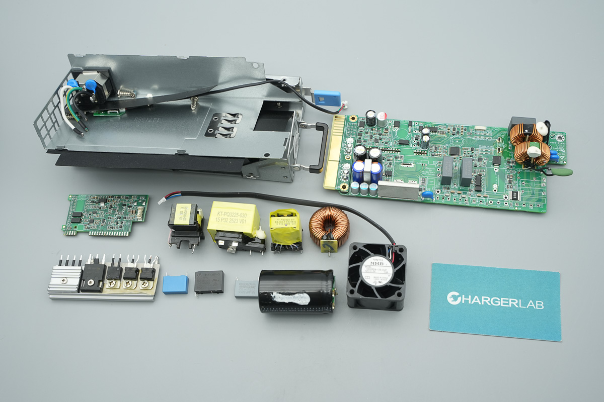
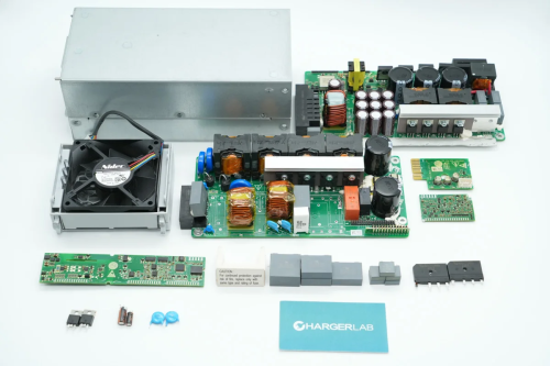
Well, those are all components of the Great Wall 800W Platinum SiC Server Power Supply.
Summary of ChargerLAB
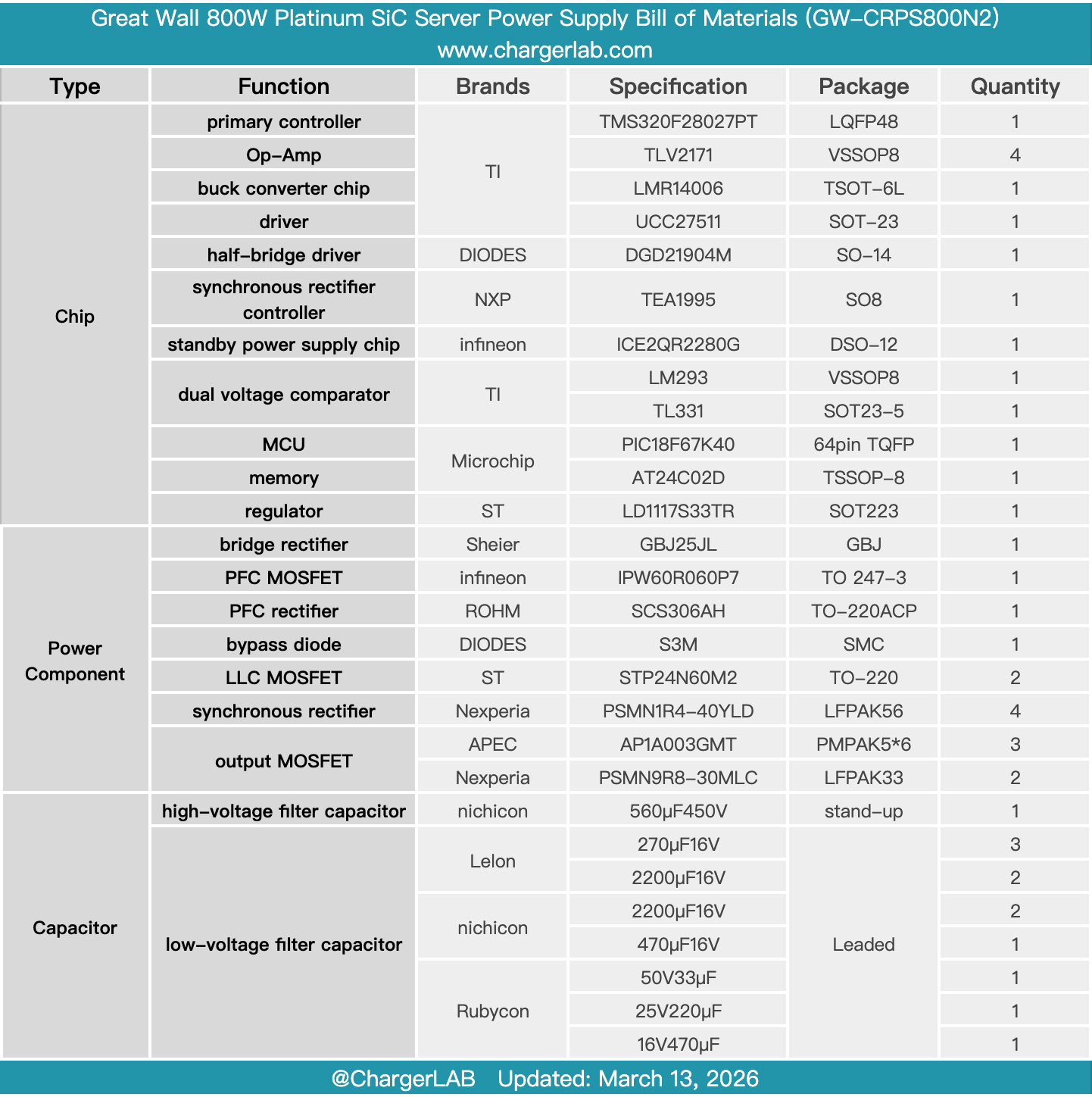
Here is the component list of the Great Wall 800W Platinum SiC Server Power Supply for your convenience.
The model is GW-CRPS800N2, supporting 100–240 V AC input and 240 V HVDC input. The rated output power is 800 W. The main output provides 12 V at 65 A, while the standby output is 12 V at 3 A. An internal cooling fan draws air in from the DC output side and exhausts it through the AC input side for heat dissipation.
After taking it apart, we found that it uses a TI controller, with the TMS320F28027 handling both PFC and LLC control. The PFC MOSFET is an Infineon IPW60R060P7, driven by a TI UCC27511, and the PFC rectifier is a ROHM SCS306AH.
The LLC stage uses STP24N60M2 MOSFETs, paired with a Diodes DGD21904M half-bridge driver. The synchronous rectifier controller is an NXP TEA1995, working with Nexperia PSMN1R4-40YLD synchronous rectifiers. The standby power supply uses an Infineon ICE2QR2280G, while communication control is handled by a Microchip PIC18F67K40. High-voltage capacitors are from Nichicon. The components are secured with adhesive, reflecting solid build quality and robust material selection.
Related Articles:
1. Teardown of Anker Nano 10000mAh Magnetic Wireless Charger Power Bank (A110Z)
2. Teardown of Apple 140W USB-C Power Adapter (A3607)
3. Teardown of HuntKey 65W Dual USB-C GaN Charger (H02)