Introduction
We obtained the Gospower T265 Titanium-series CRPS power supply, model G1236-3000WNA. It supports 100–240 V AC as well as +240 V HVDC input and is certified to the 80 PLUS Titanium efficiency standard. The main output is rated at 12.2 V and 245 A, with a 12 V, 3 A standby rail.
The input side features a cooling fan, power inlet, and status indicators, while the output side uses a gold-finger edge connector. Internally, the design follows a PFC + LLC + synchronous rectification topology, built around Texas Instruments controllers and equipped with PMBus communication. The following teardown examines the internal design and component selection of this 3000W Titanium server power supply from Gospower.
Product Appearance
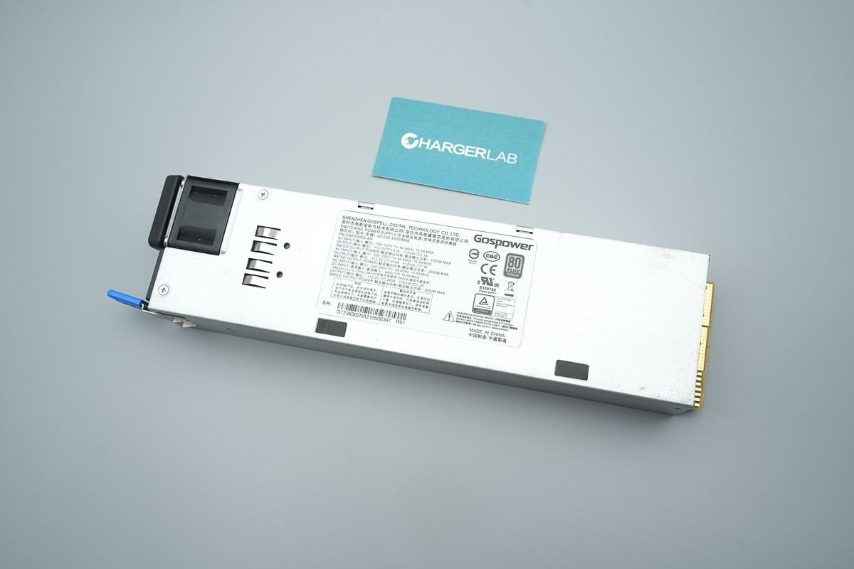
The power supply uses a metal enclosure with a specification label affixed to the front.
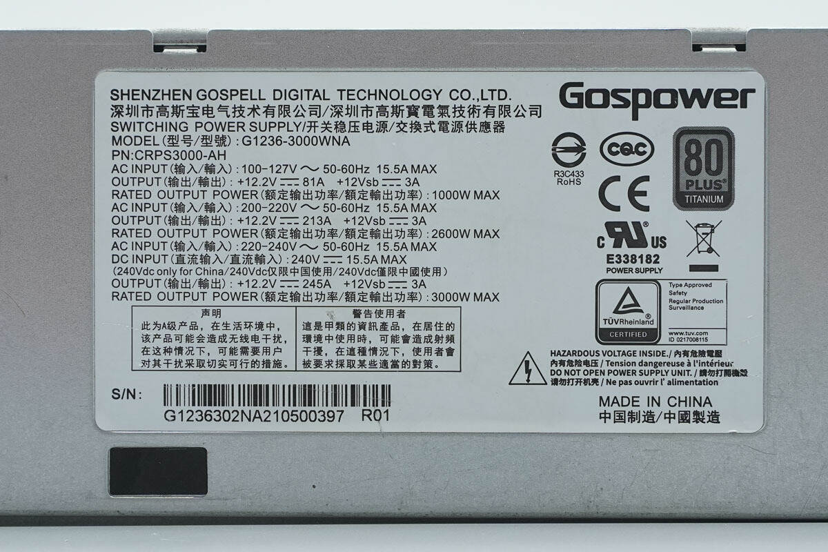
Model: G1236-3000WNA
PN: CRPS3000-AH
Input: 100–127 V ~ 50–60 Hz 15.5 A Max
Output: +12.2 V ⎓ 81 A +12 Vsb ⎓ 3 A
Rated Output Power: 1000 W Max
Input: 200–220 V ~ 50–60 Hz 15.5 A Max
Output: +12.2 V ⎓ 213 A +12 Vsb ⎓ 3 A
Rated Output Power: 2600 W Max
Input: 220–240 V ~ 50–60 Hz 15.5 A Max
DC Input: 240 V ⎓ 15.5 A Max
Output: +12.2 V ⎓ 245 A +12 Vsb ⎓ 3 A
Rated Output Power: 3000 W Max
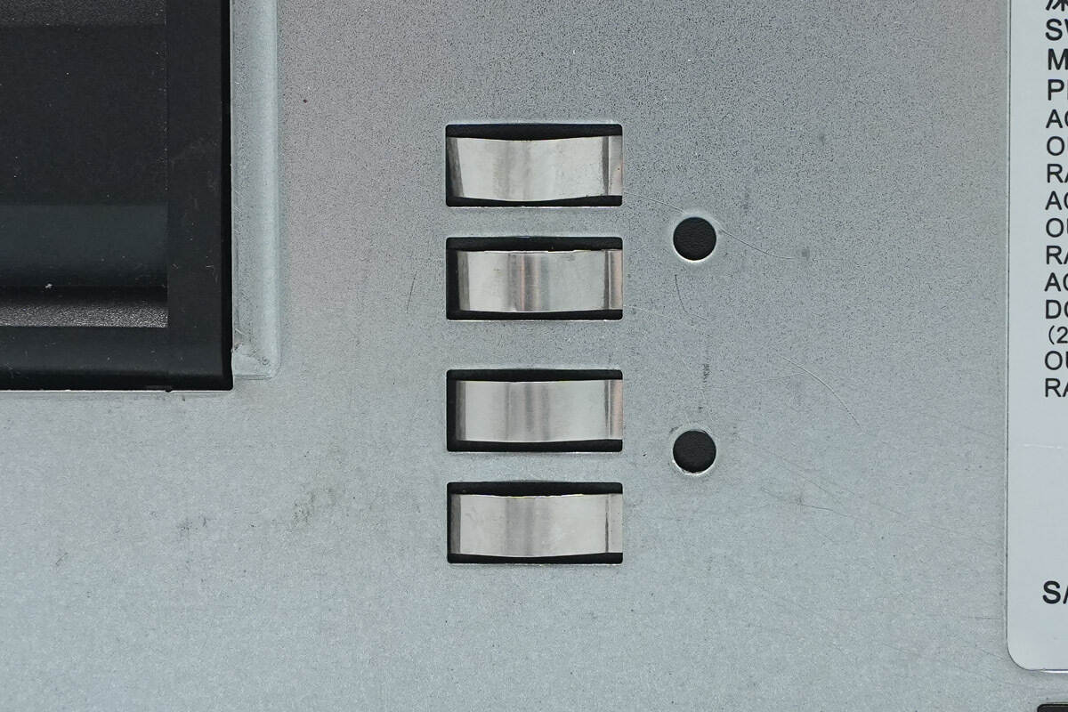
Close-up of the grounding springs on the front side.
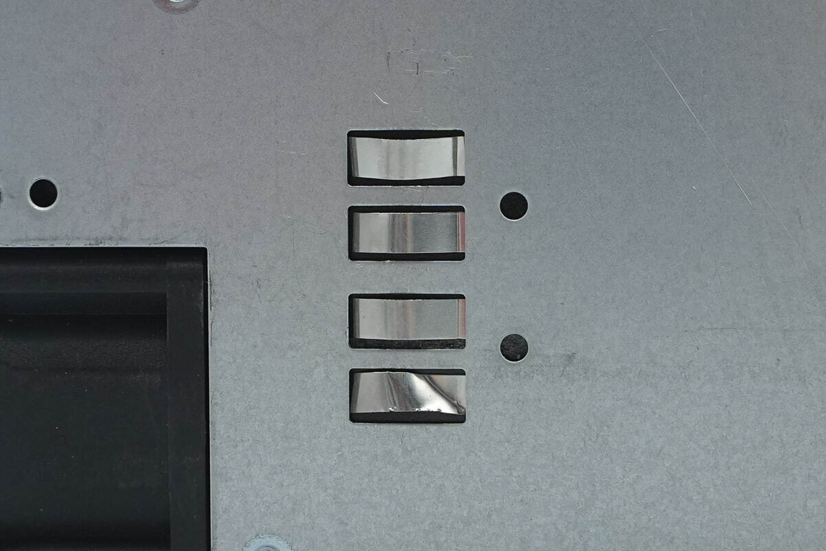
Grounding springs are also provided on the rear side.
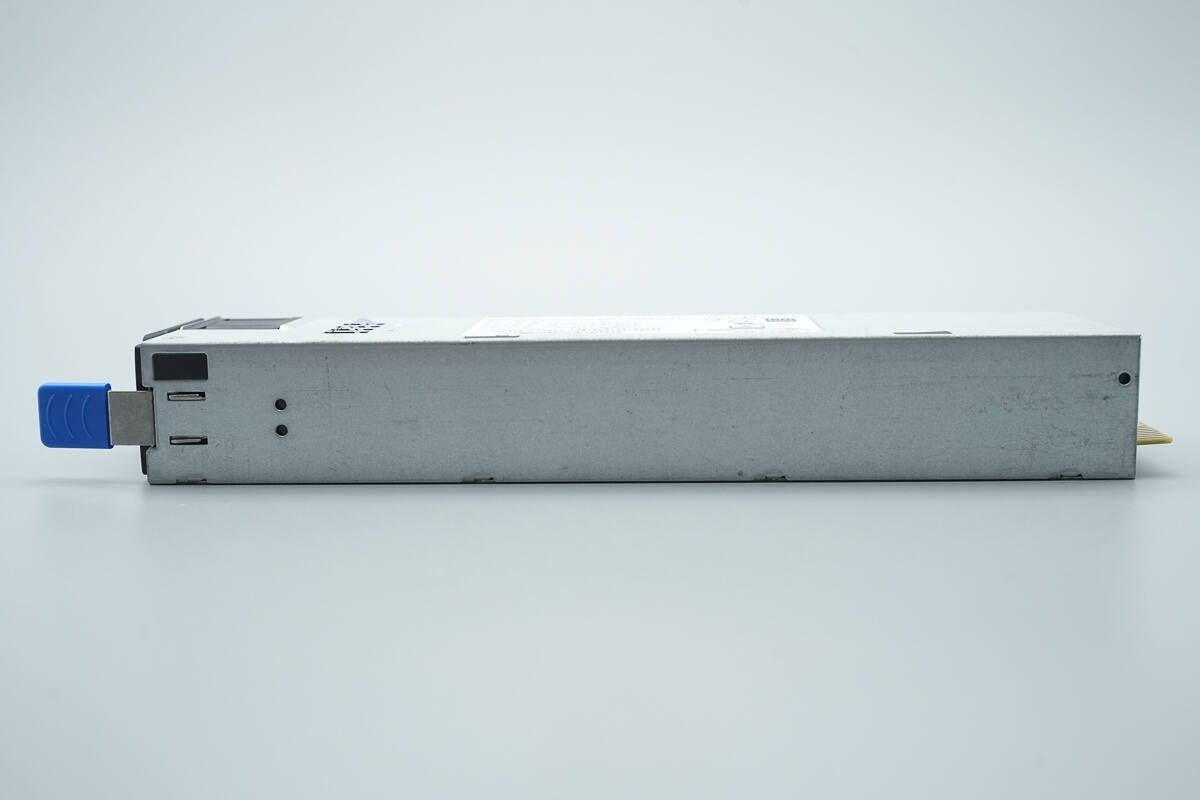
A retaining latch is located on the side.
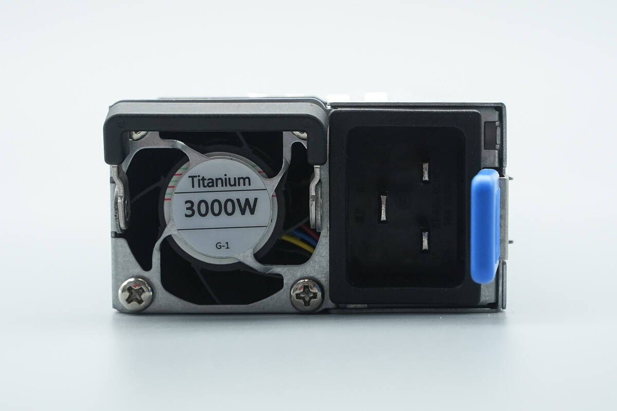
The input end features a handle, cooling fan, input socket, indicator light, and a release lever.
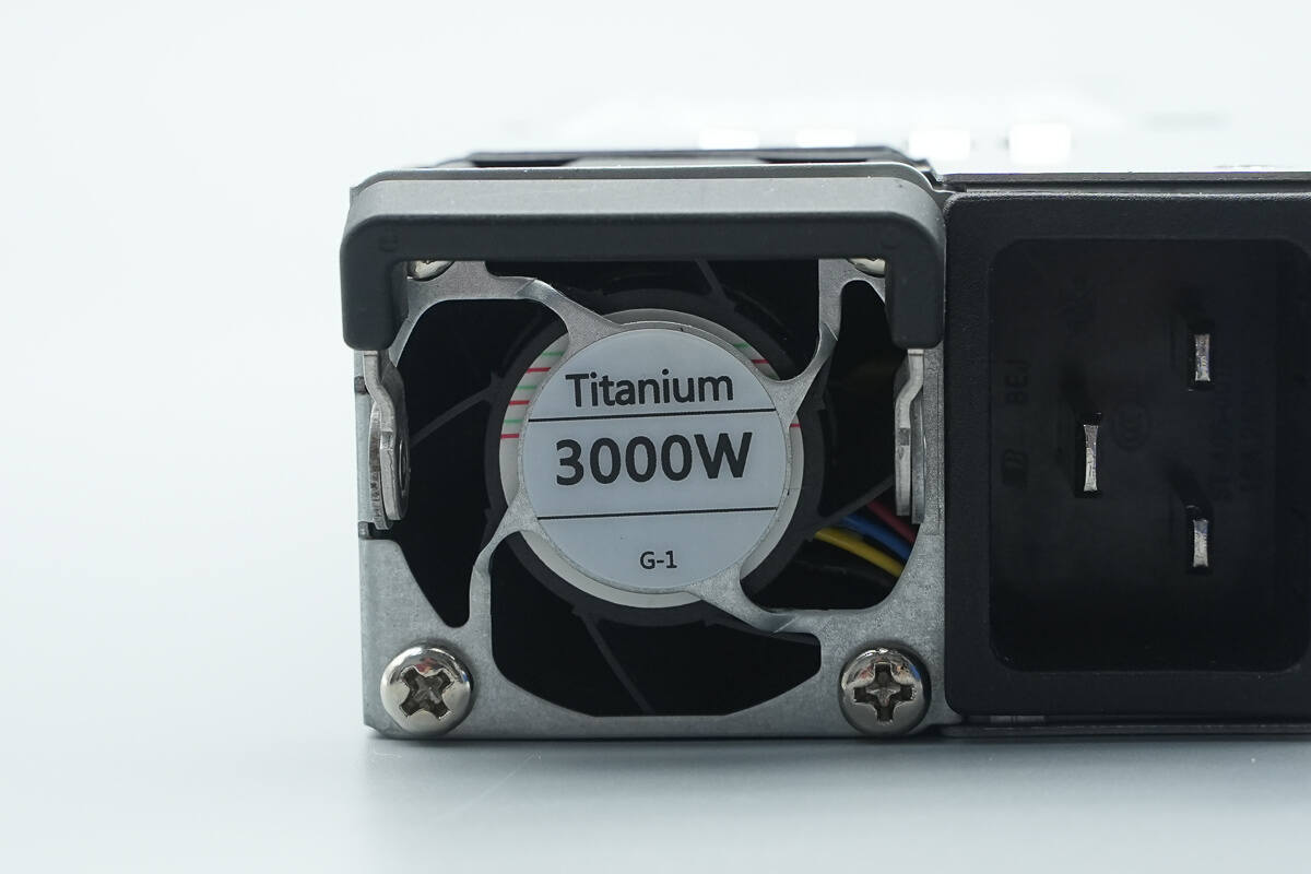
The cooling fan is marked with “Titanium” and “3000W.”
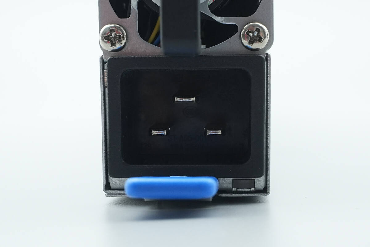
It uses a C20 power inlet, with an LED indicator located at the bottom right corner.
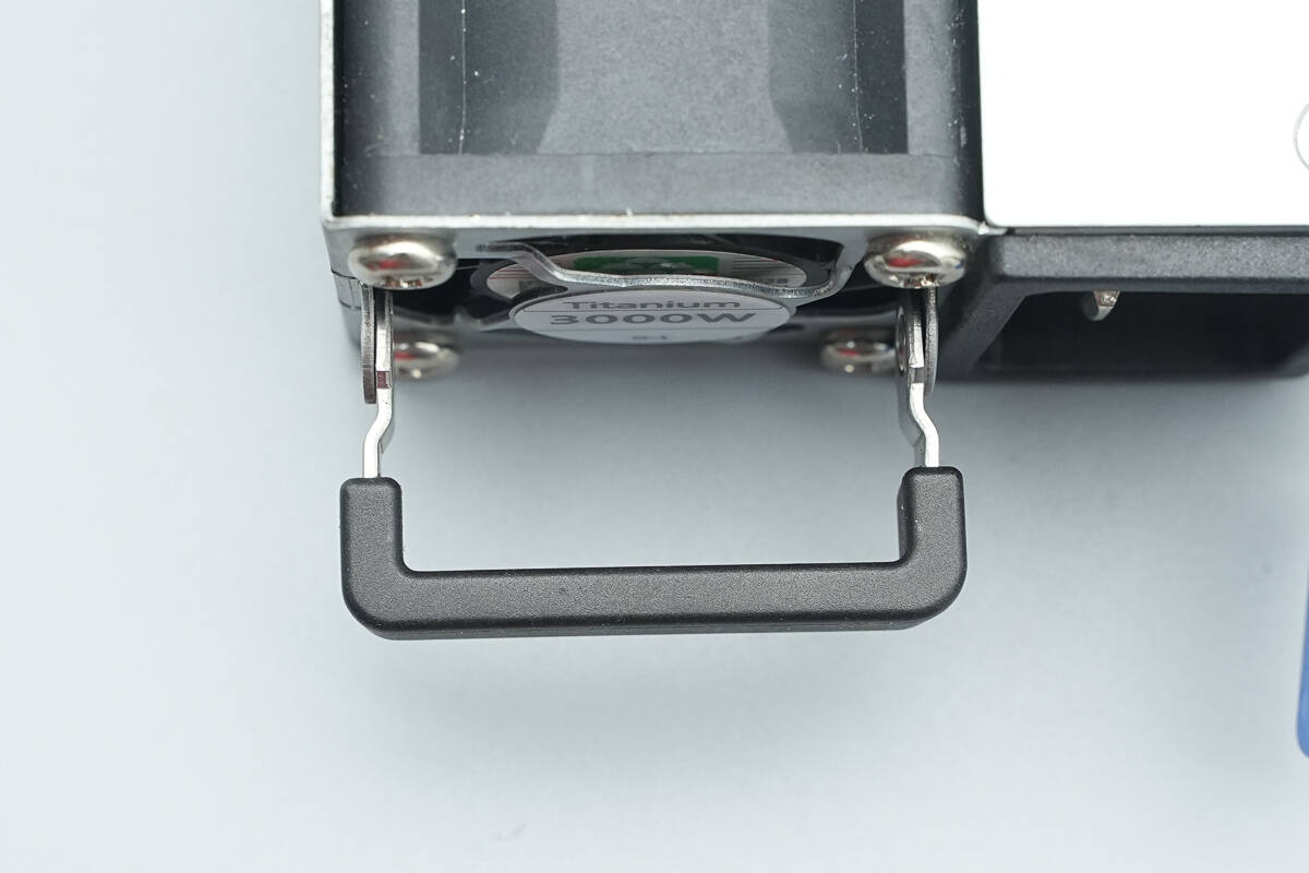
Close-up of the mounting handle.
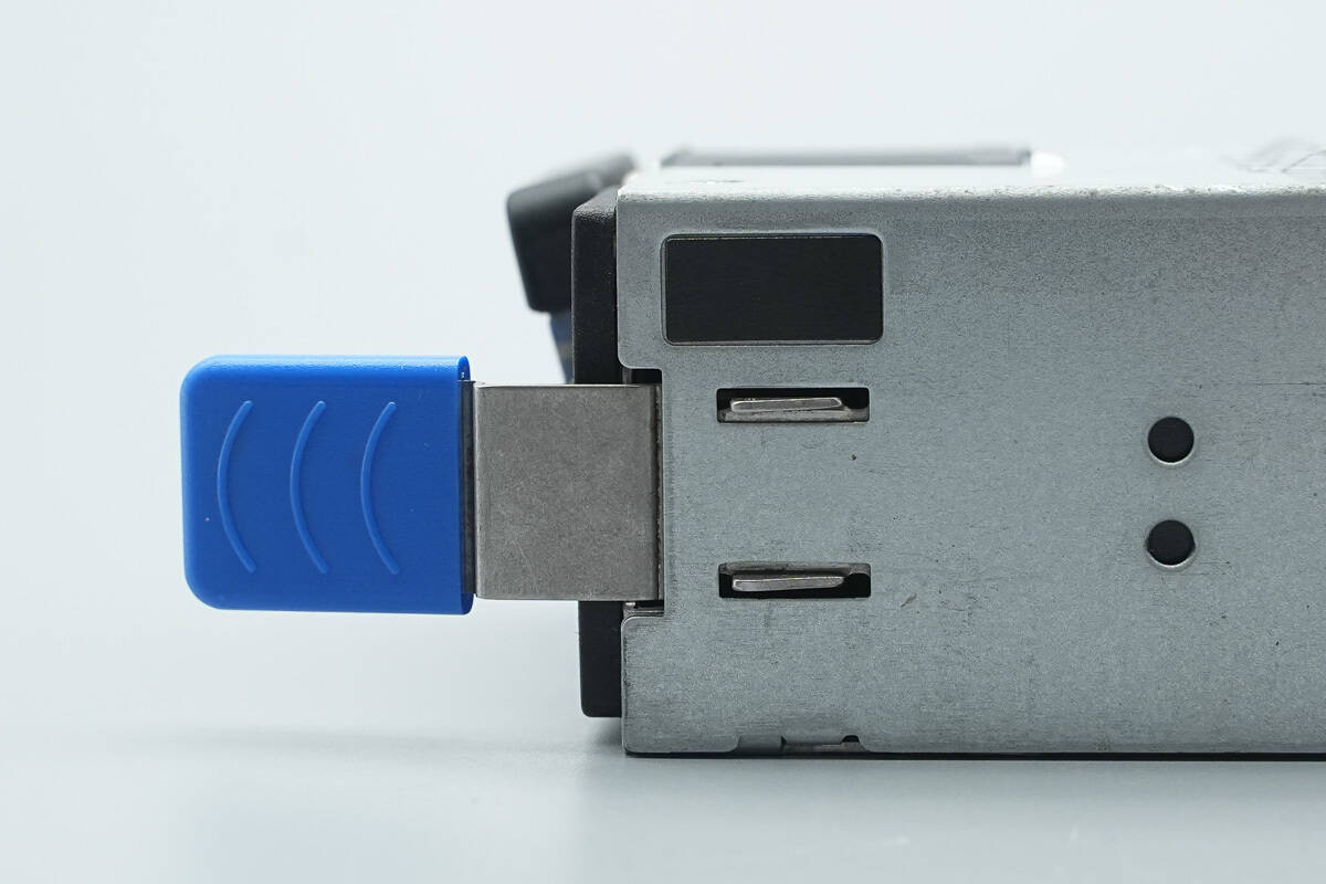
Close-up of the release lever.
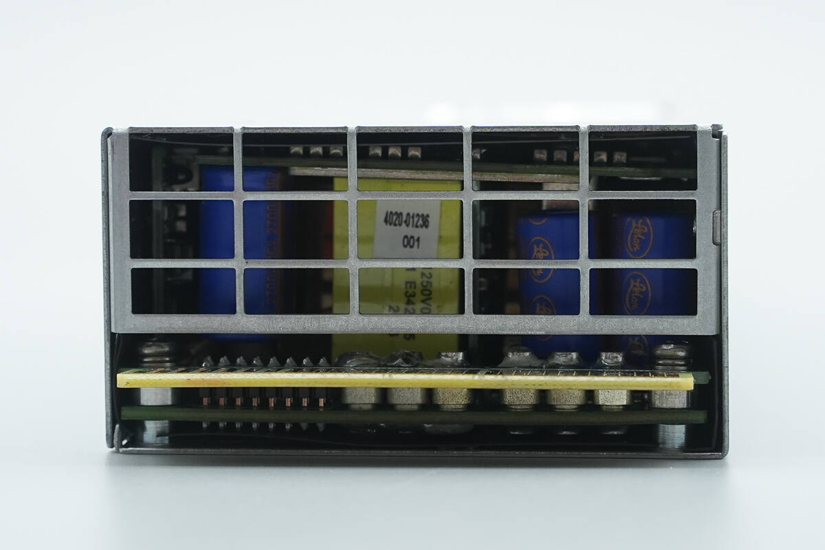
The output side features a grille and a gold-finger daughterboard. Through the grille, the internal components are visible.
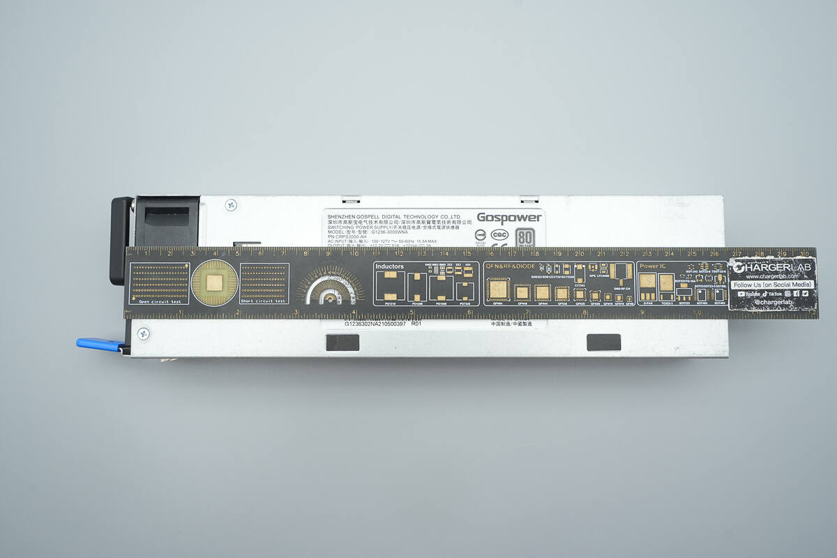
The length is about 265 mm (10.43 inches).
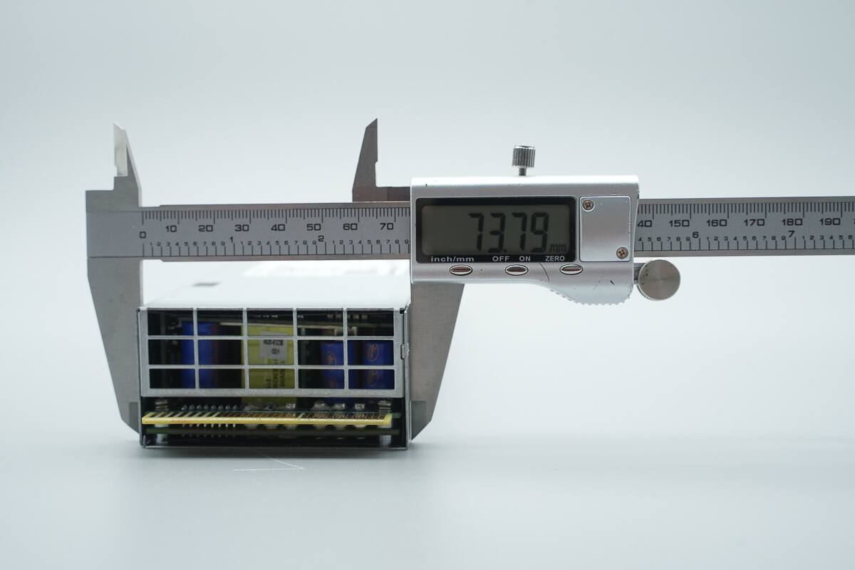
The width is about 73.8 mm (2.91 inches).
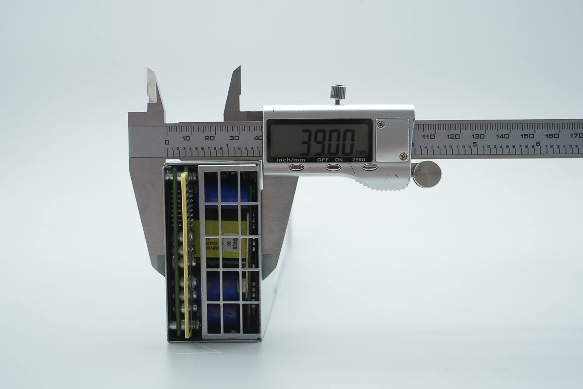
The thickness is about 39 mm (1.54 inches).
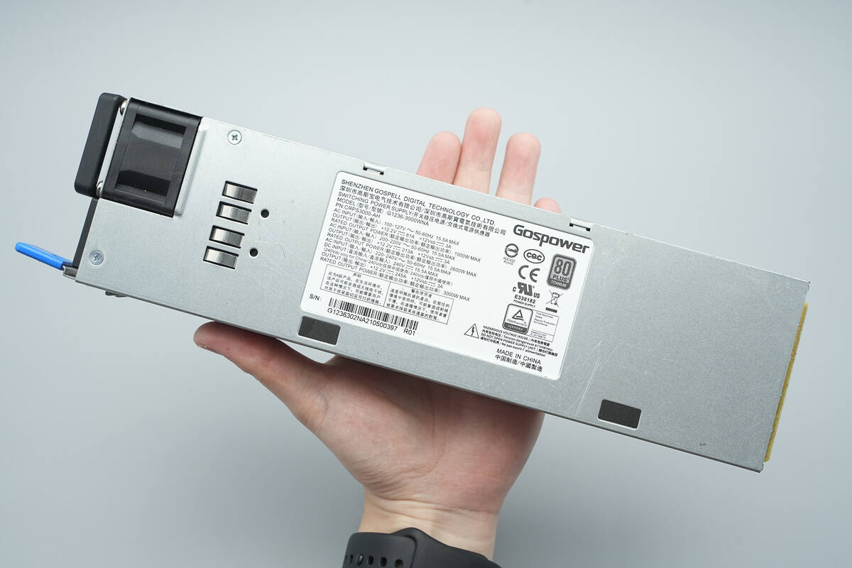
That's how big it is in the hand.
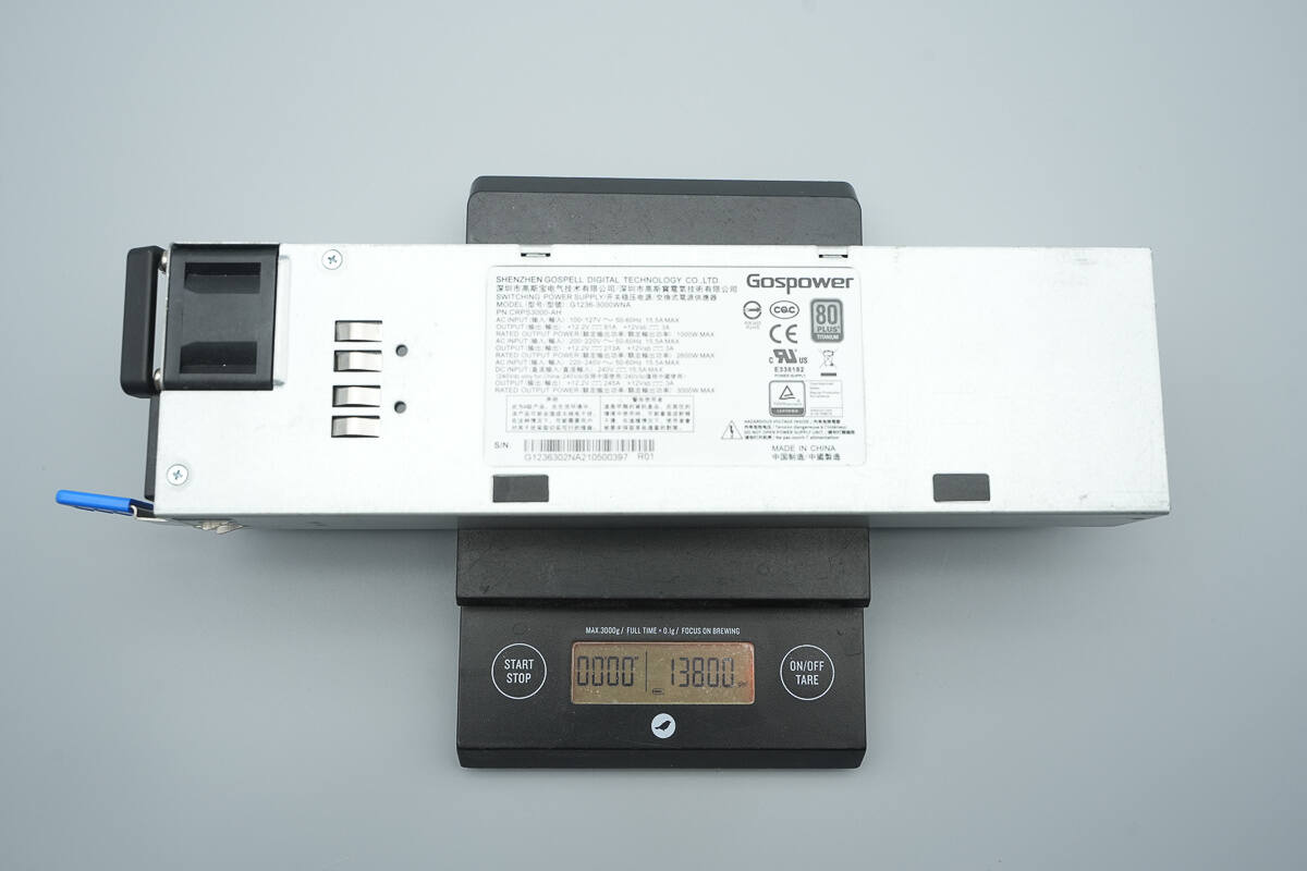
The weight is about 1380 g (48.68 oz).
Teardown
Next, let's take it apart to see its internal components and structure.
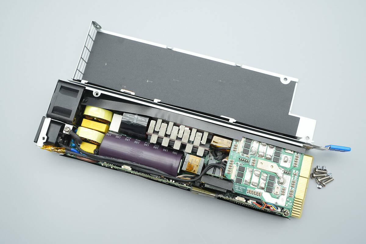
Unscrew the screws and remove the enclosure.
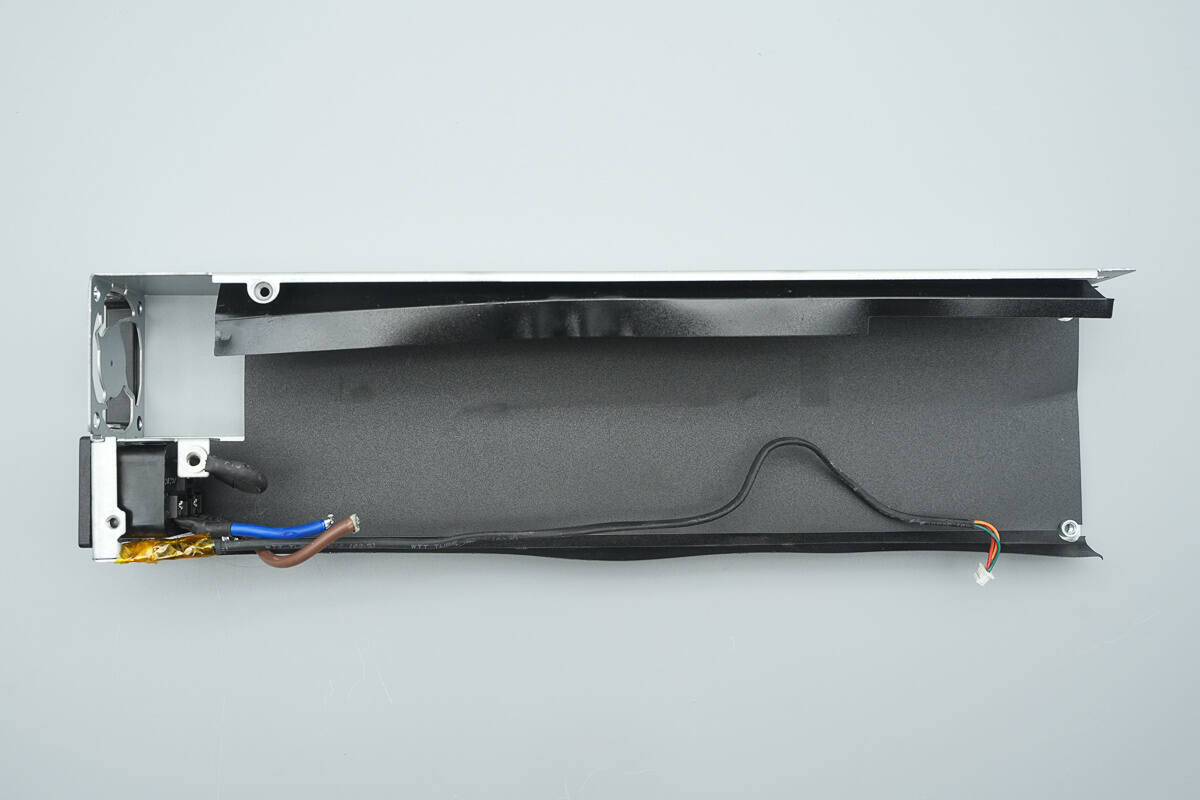
The interior of the enclosure is lined with a Mylar sheet.
The PCBA module is secured with screws.
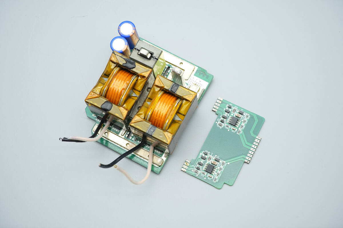
The transformer’s secondary windings are soldered onto a small PCB.
The cooling fan and indicator light are connected to the control PCB via connectors.
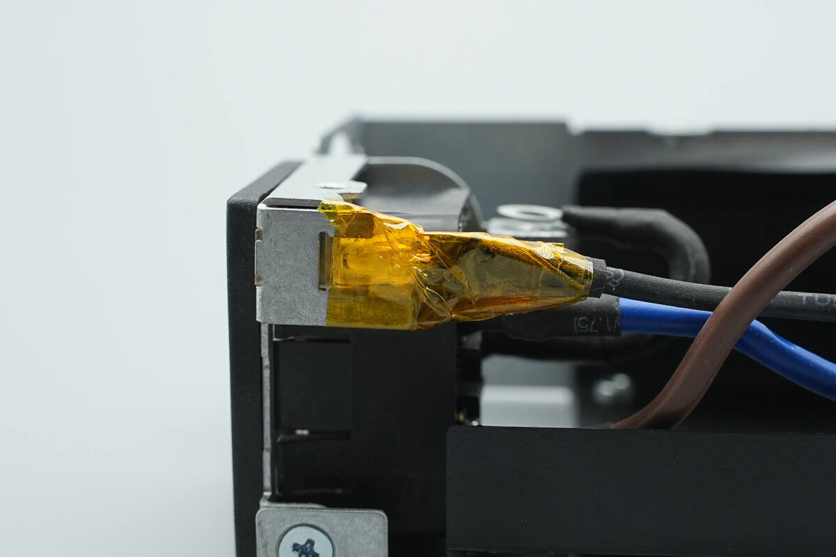
The input wires are connected via crimped terminals and soldered in place.
Cut the input wires, remove the cooling fan and indicator lights, unscrew the screws, and take out the PCBA module.
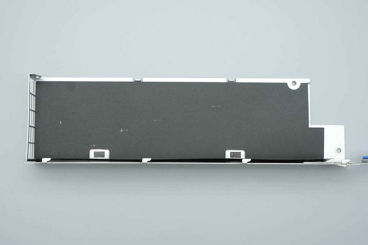
The interior is equipped with a Mylar insulation sheet.
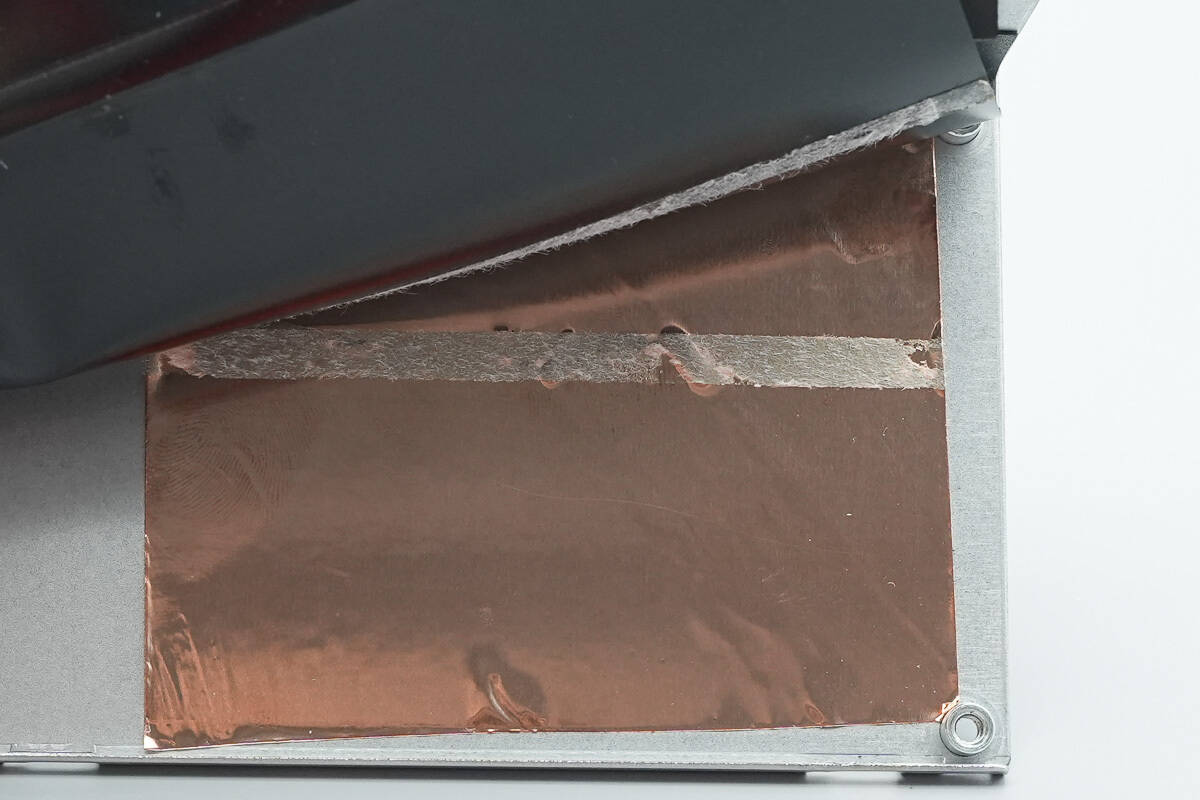
There is a shielding copper foil on the bottom side of the Mylar sheet.
The LED indicator is used to show the operating status of the power supply.
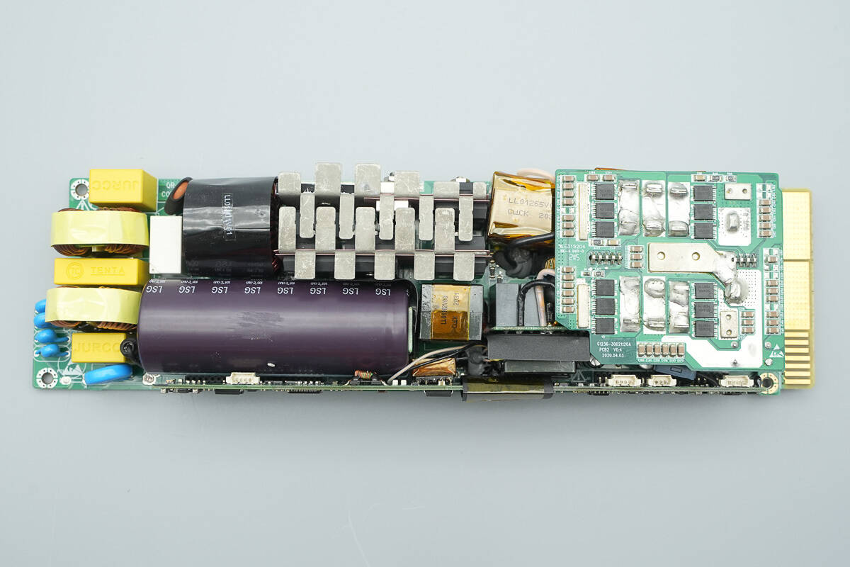
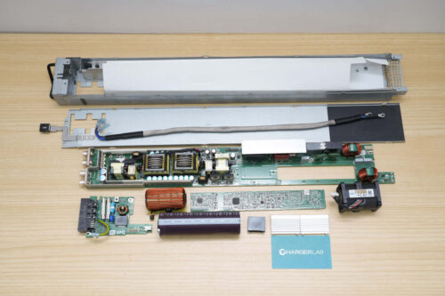
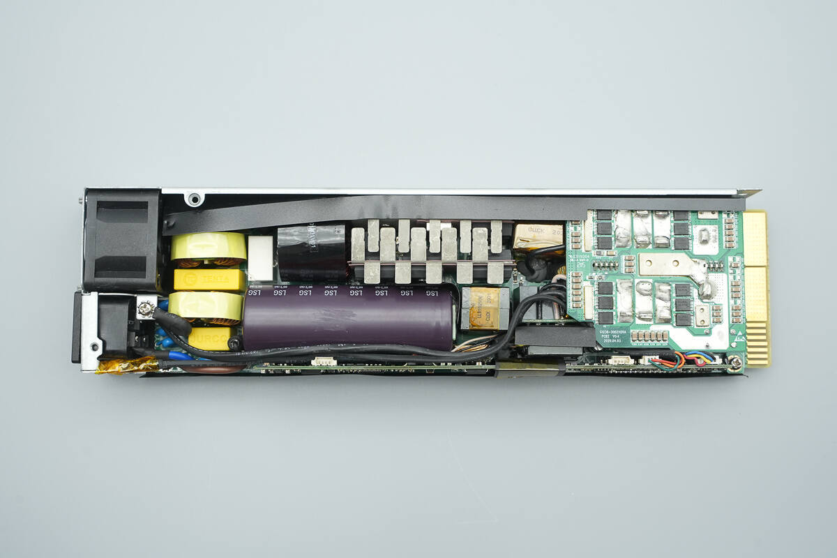
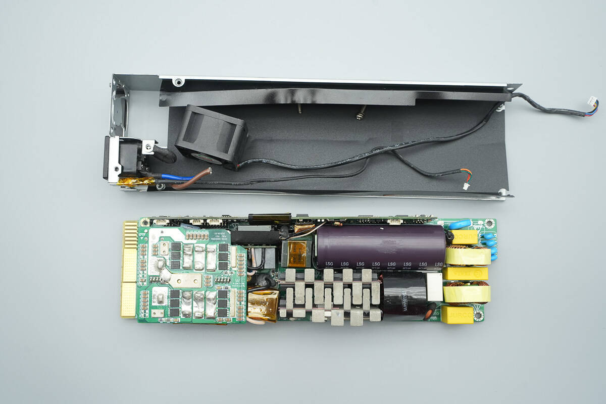
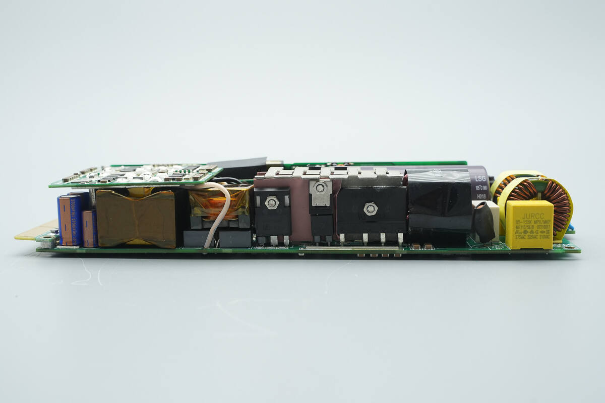
On the front side of the PCBA module, there are components such as fuses, varistors, safety X2 capacitors, Y capacitors, common mode chokes, thermistors, relays, PFC boost inductors, bridge rectifiers, PFC rectifiers, PFC MOSFETs, LLC MOSFETs, high-voltage filter capacitors, resonant inductors, resonant capacitors, standby power transformers, synchronous rectifiers, filter capacitors, LLC transformers, and other components.
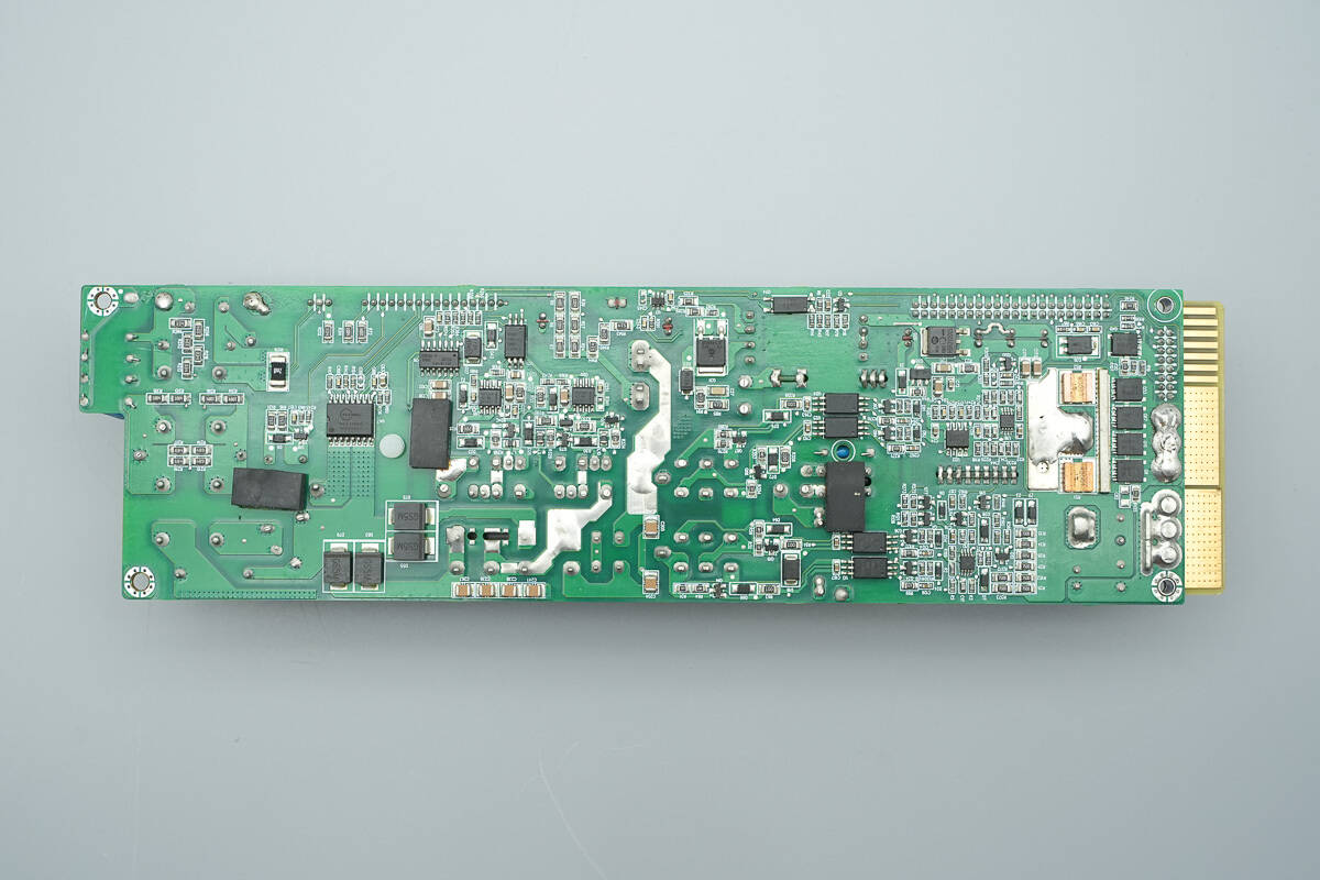
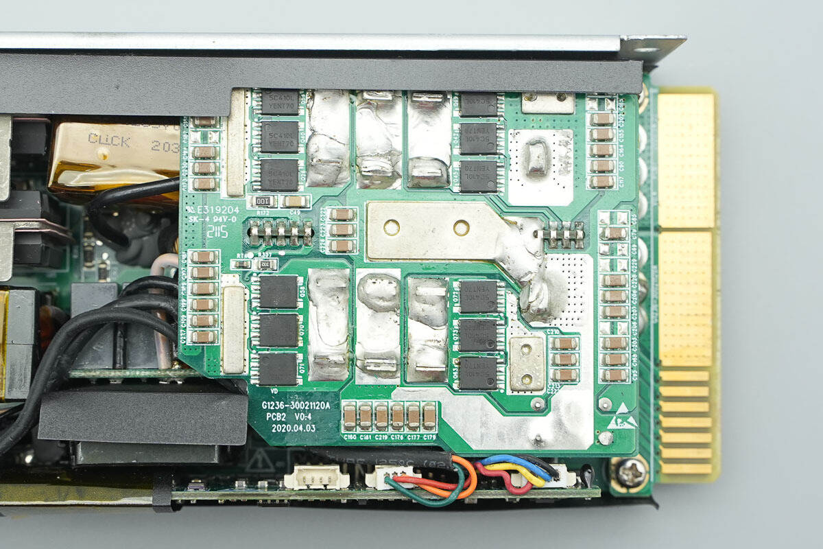
On the rear side, there are components such as current-sensing chips, rectifier diodes, half-bridge drivers, isolated drivers, standby power MOSFETs, rectifiers, current-sensing resistors, and output control MOSFETs.
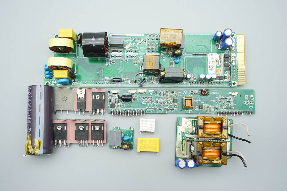
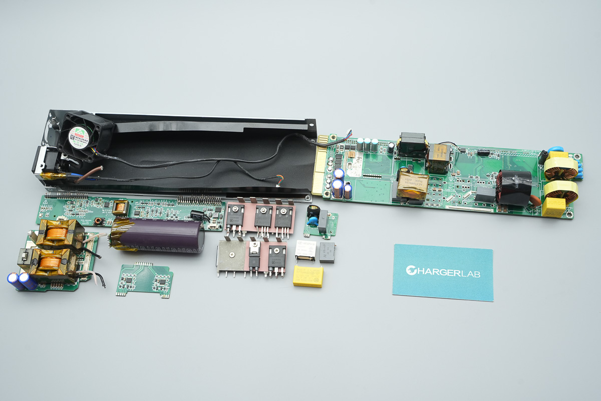
Remove some of the components.
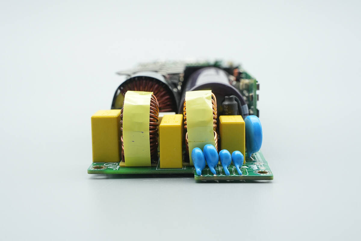
The input side contains a fuse, a varistor, safety X2 capacitors, blue Y capacitors, and common mode chokes.
This side has a varistor, a fuse, and a control PCB.
The input fuse is insulated with a heat-shrink tube.
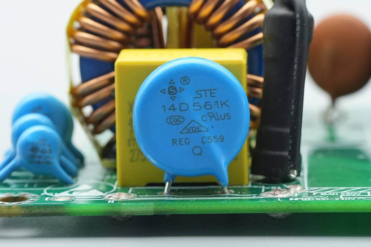
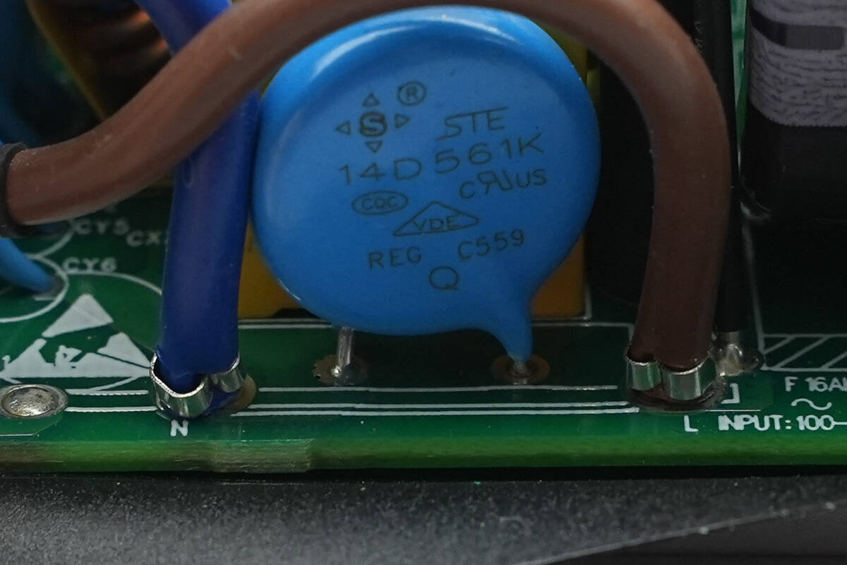
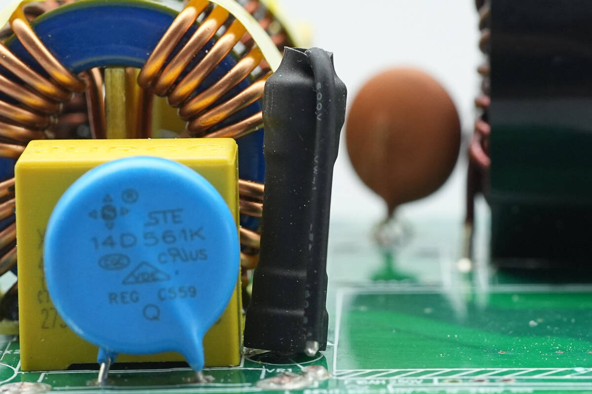
The varistor is from STE, model 14D561K, and is used to absorb overvoltage surges.
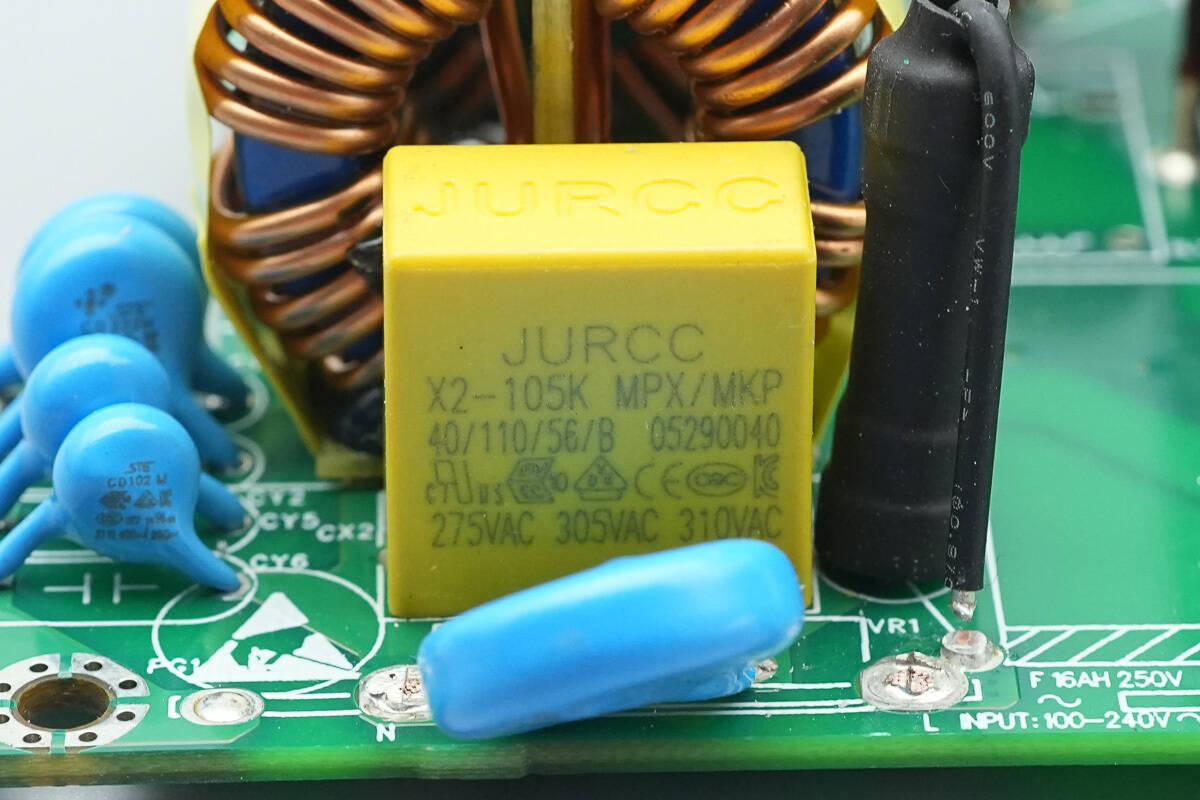
The safety X2 capacitor is from JURCC, with a rating of 1 μF.
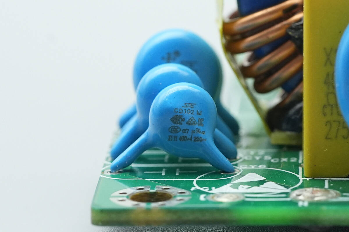
The blue Y capacitor is from STE, model CD102M.
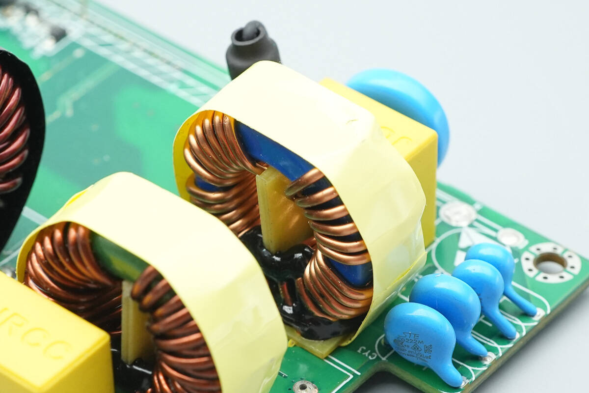
The common-mode choke is wound with enameled wire, has a bakelite base, and is insulated with tape wrapping.
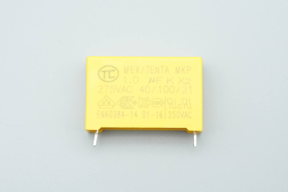
The safety X2 capacitor is from TC, with a rating of 1 μF.
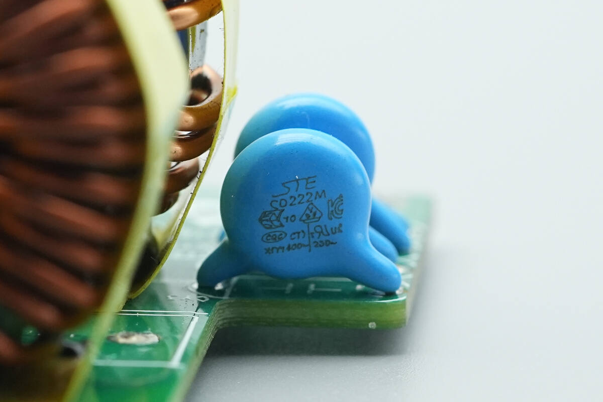
The blue Y capacitor is from STE, model CD222M.
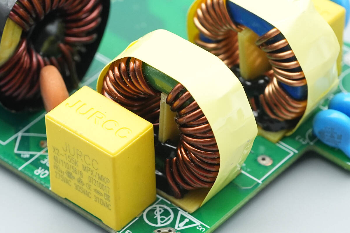
Another common-mode choke is also wound with enameled wire.
This side contains components such as safety X2 capacitors, NTC thermistors, PFC boost inductors, bridge rectifiers, PFC rectifiers, LLC MOSFETs, resonant capacitors, resonant inductors, transformers, output filter capacitors, and other components.
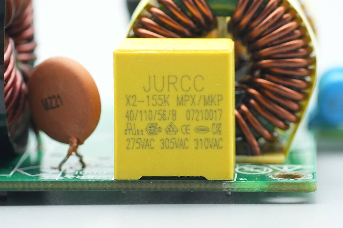
The safety X2 capacitor is from JURCC, with a rating of 1.5 μF.
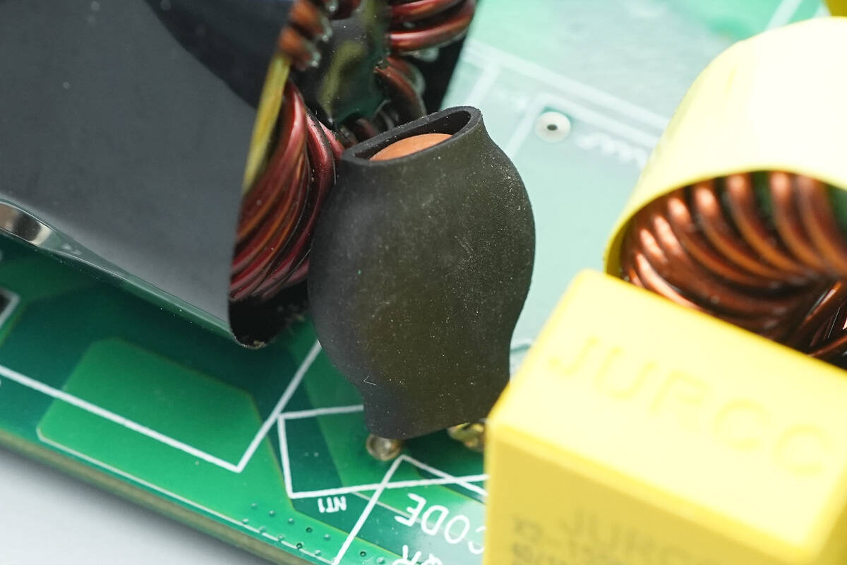
The thermistor is insulated with a heat-shrink tube.
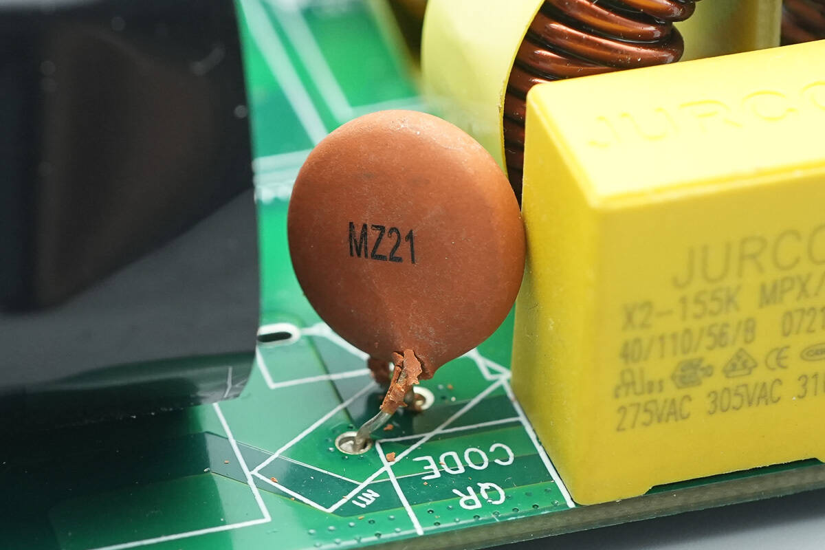
The thermistor is from FNR, model MZ21, and is used to suppress inrush current at power-on.
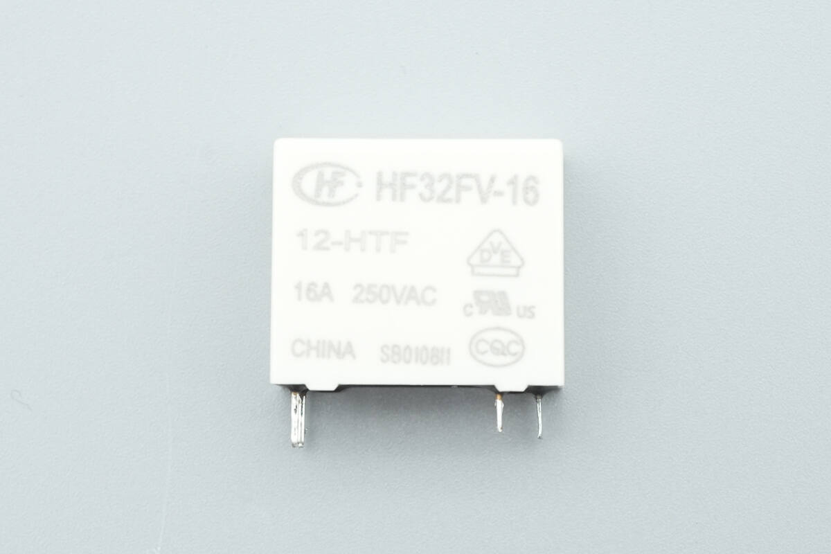
The relay used with the short-circuit thermistor is from HONGFA, model HF32FV-16/12-HTF. It is an ultra-compact, high-power relay with a single normally open contact, rated at 16 A 250 VAC, and has a 12 V coil.
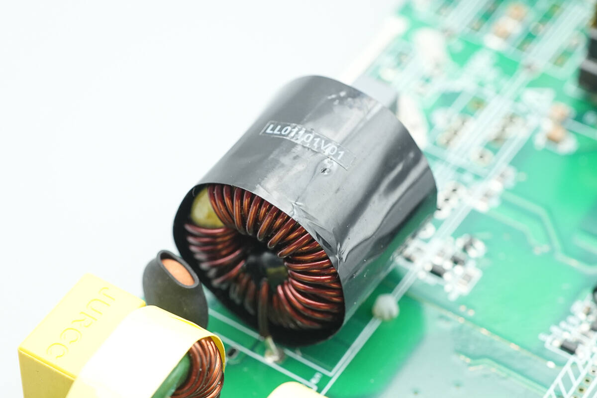
The PFC boost inductor is wound with enameled wire and insulated with tape wrapping.
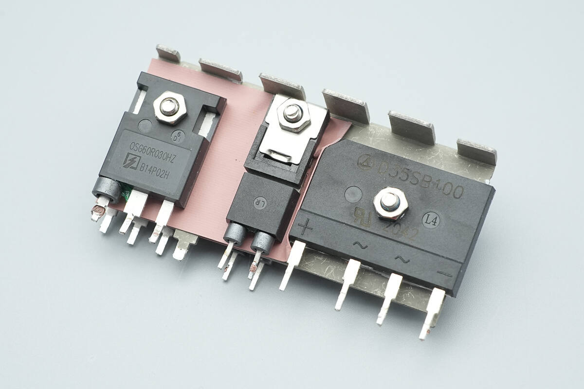
The heatsink holds the bridge rectifier, PFC rectifiers, and LLC MOSFETs.
The other side features PFC rectifiers and LLC MOSFETs.
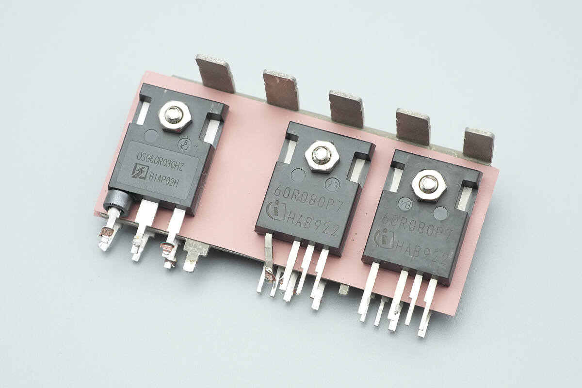
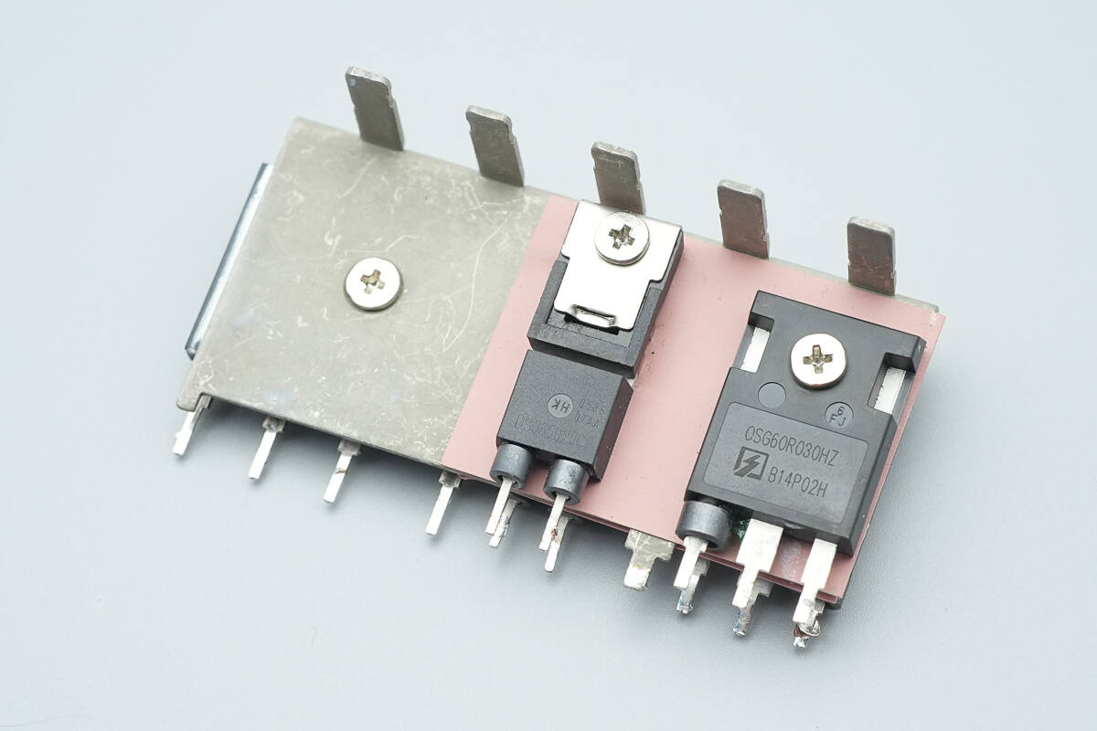
Another heatsink is equipped with one LLC MOSFET and two PFC MOSFETs.
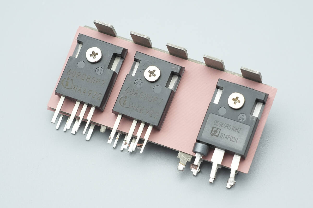
The other side of the heatsink is equipped with two PFC MOSFETs and one LLC MOSFET.
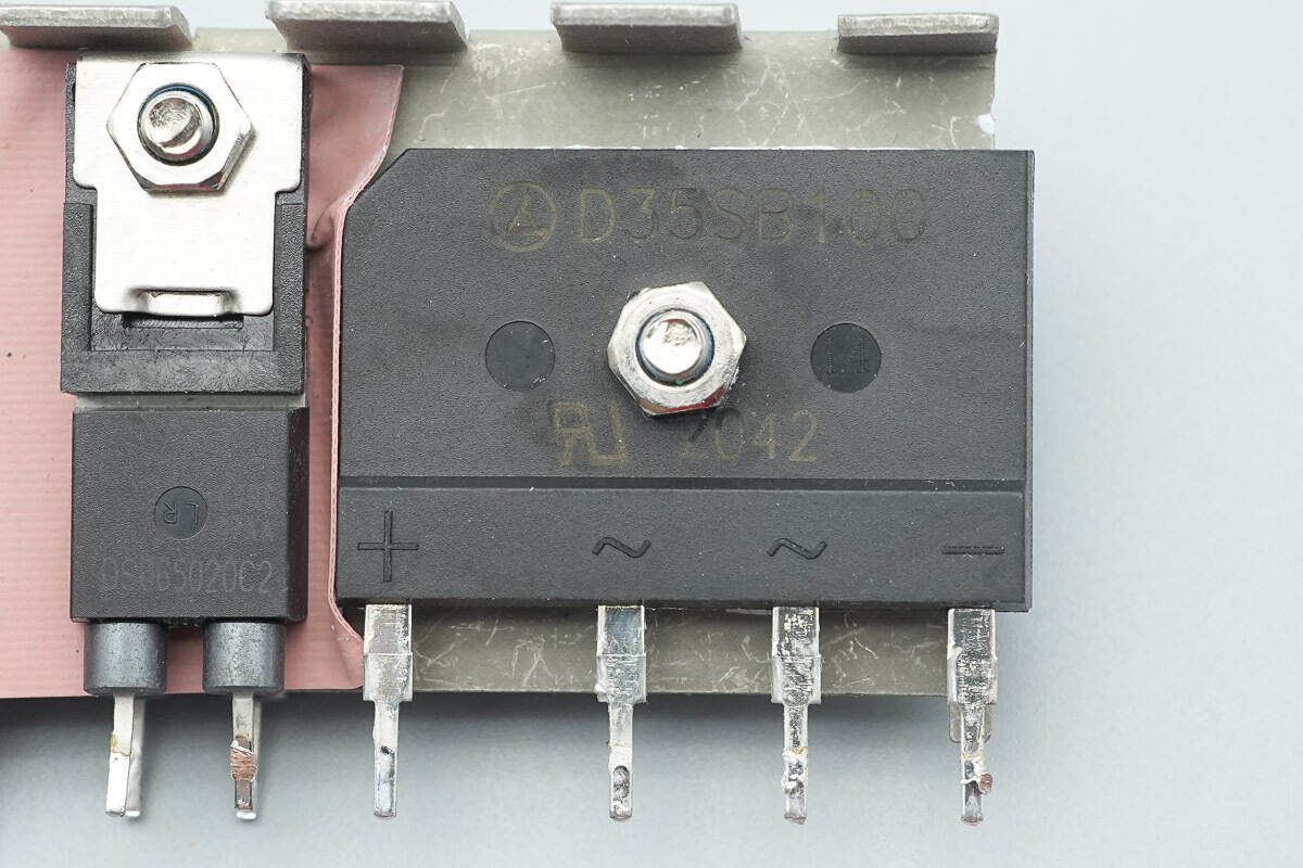
The bridge rectifier is from LRC, model D35SB100, rated for 35 A and 1000 V, and uses a D5 package.
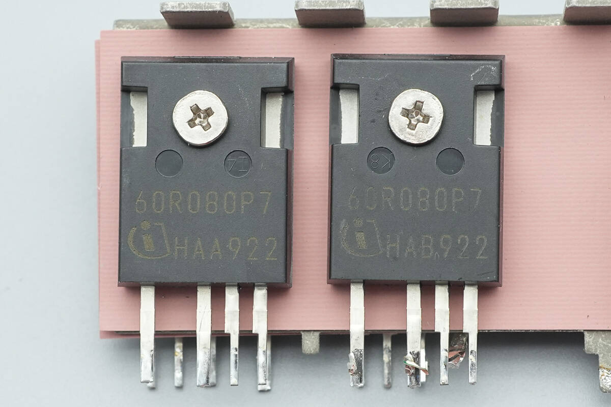
The PFC MOSFETs are from Infineon, marked with 60R080P7, model IPZA60R080P7. They are NMOS transistors with a voltage rating of 650 V, an Rds(on) of 80 mΩ, and come in a TO247-4-3 package.
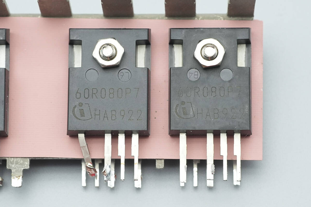
On the other side, there are two PFC MOSFETs with the same model.
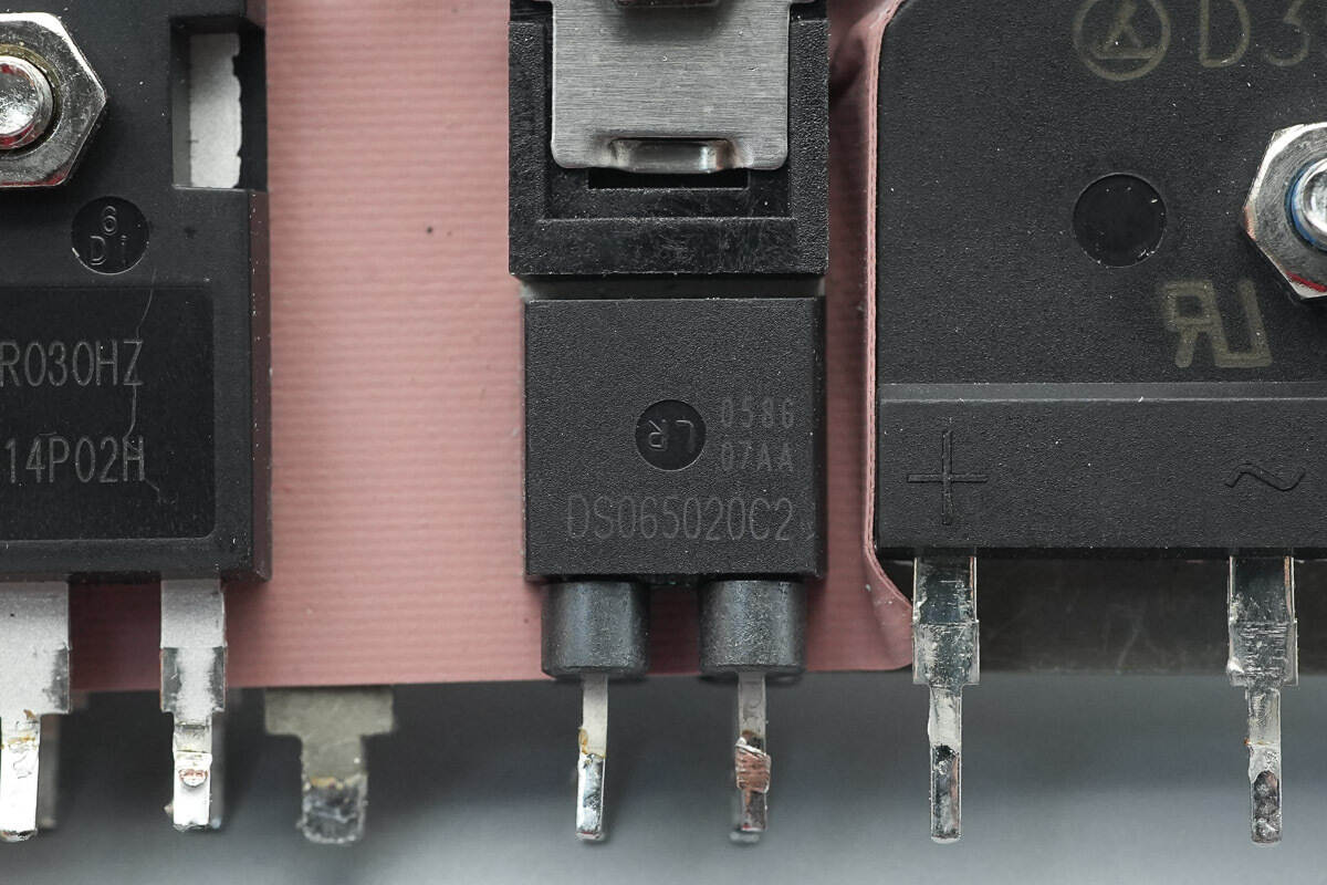
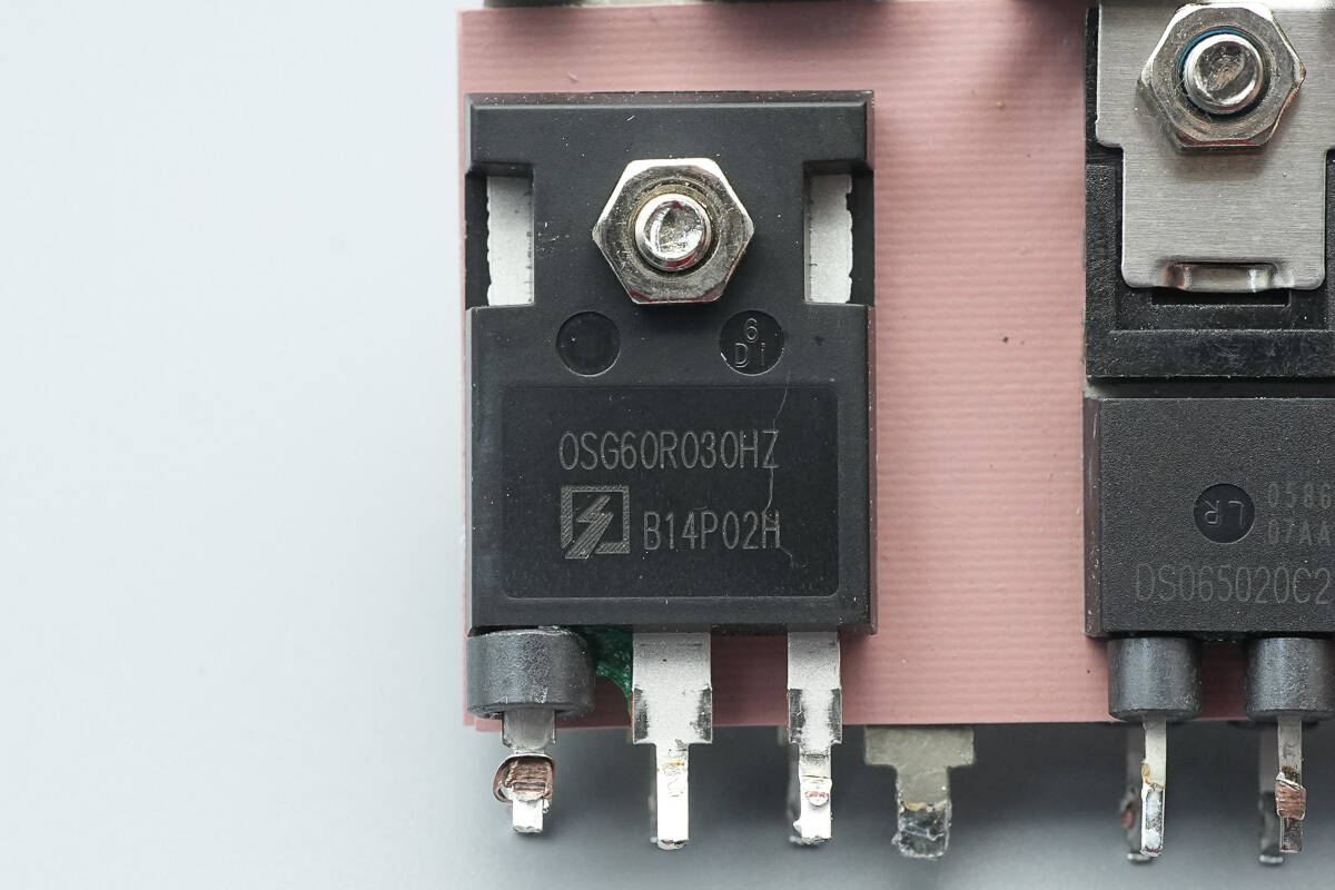
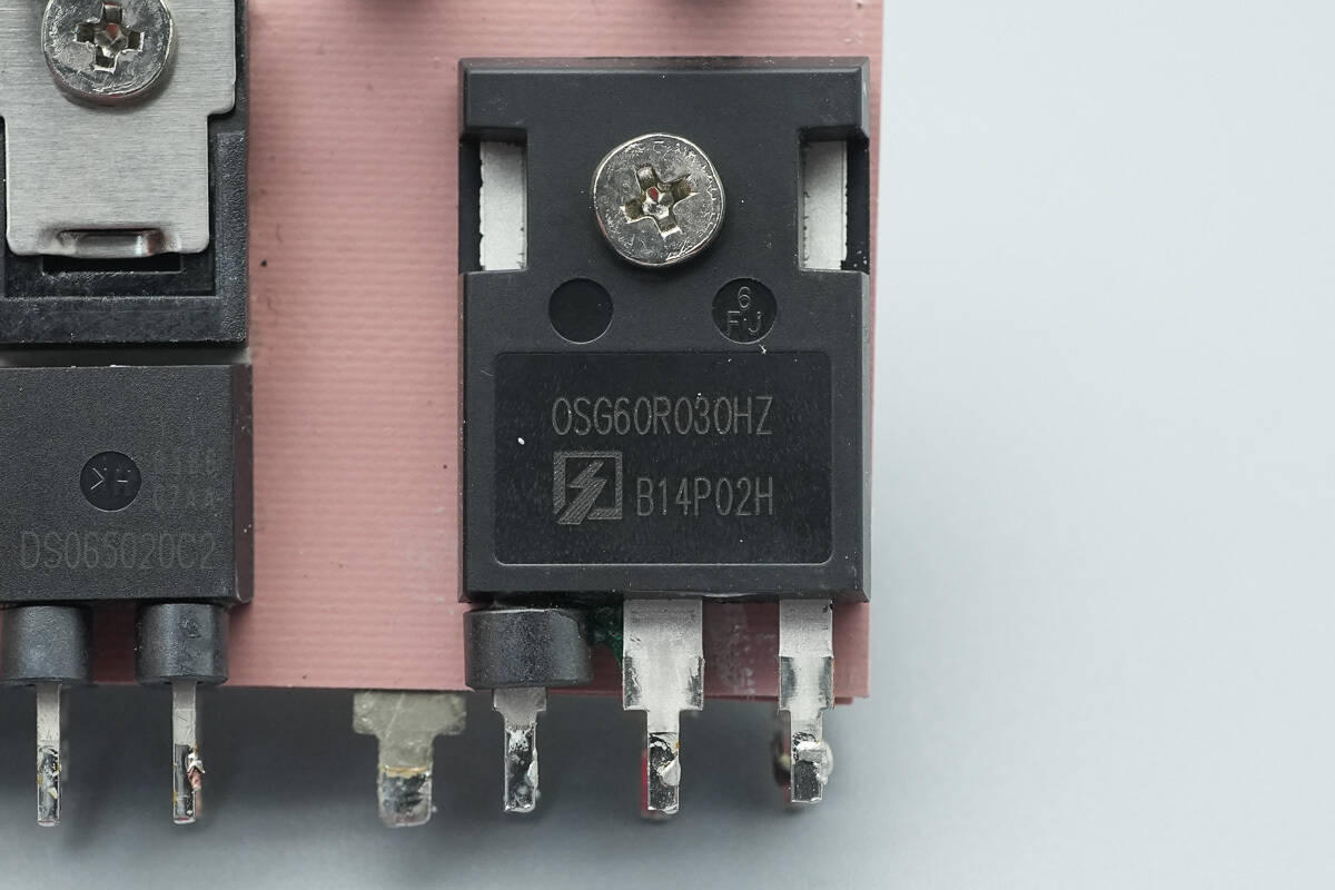
The PFC rectifier is from Sanan, marked with DS065020C2, model SDS065J020C2. It is rated for 650 V and 20 A, and comes in a TO-220-2L package.

The other PFC rectifier has the same model.
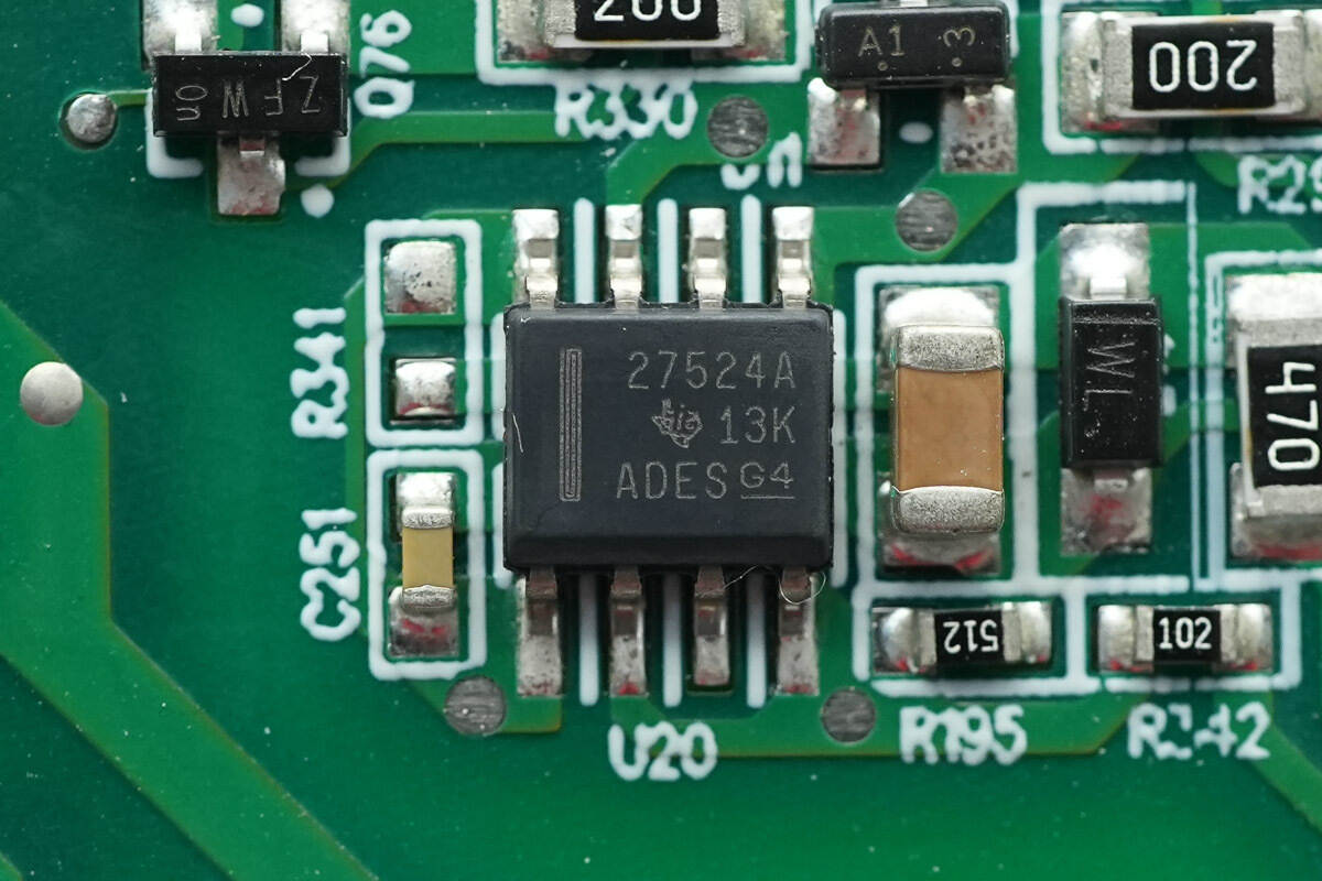
The low-side driver is from TI, model UCC27524A. It is a dual-channel 5A high-speed low-side gate driver with the ability to handle negative input voltage, and it comes in an SOIC8 package.
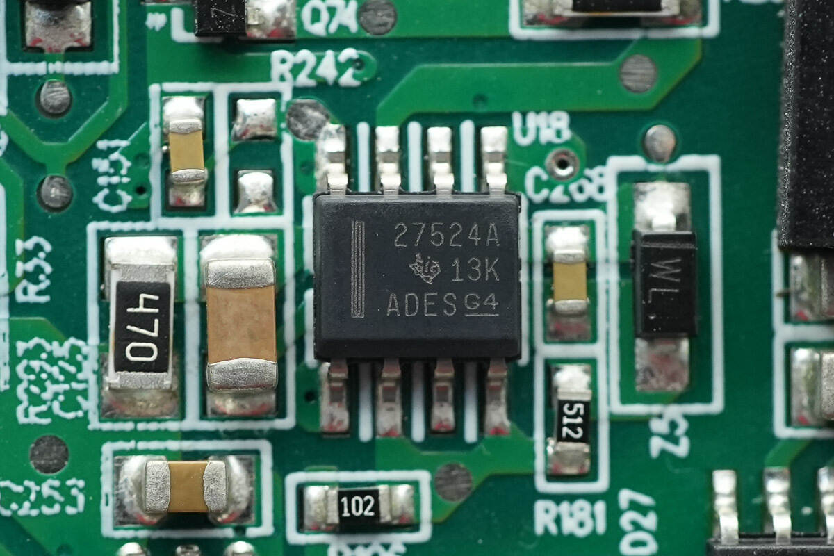
The other driver has the same model.
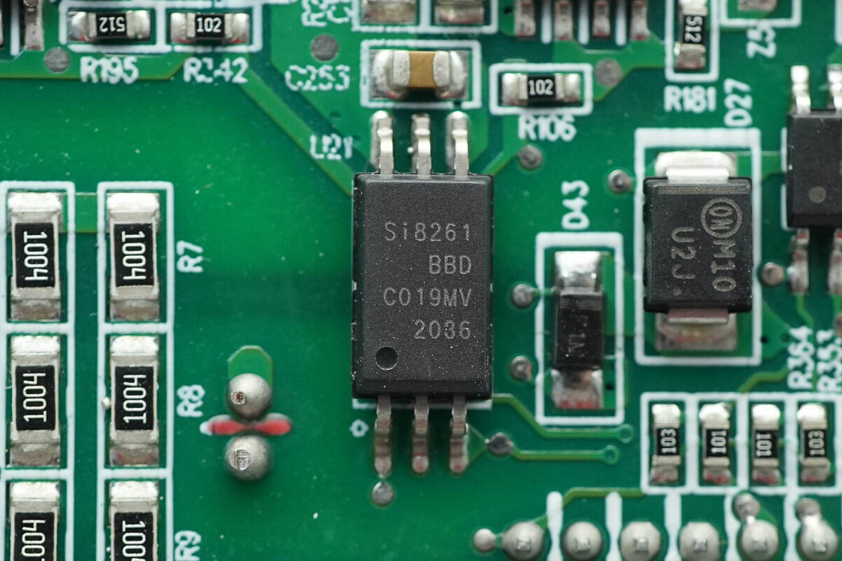
The isolation driver is from SKYWORKS, model Si8261BBD-C. It has a 4A drive capability and 5 kVrms isolation, and comes in an SDIP-6 package.
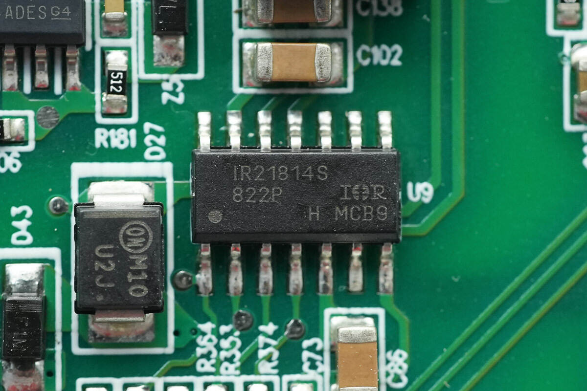
The driver is from Infineon, model IR21814S. It is a 600 V-rated high-side and low-side gate driver and comes in an SOIC14 package.
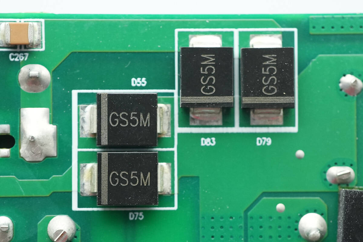
Four GS5M diodes are used for auxiliary rectification.
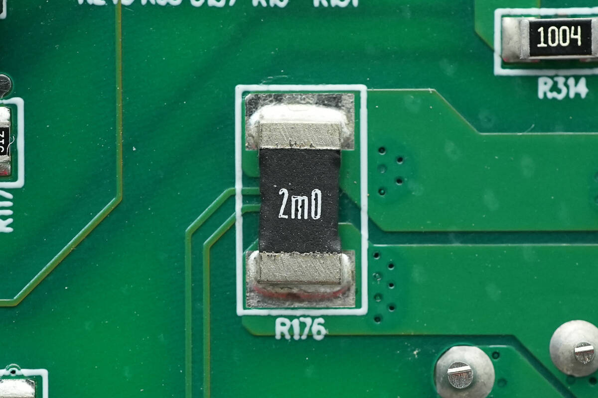
A 2 mΩ shunt resistor is used for input AC sensing.
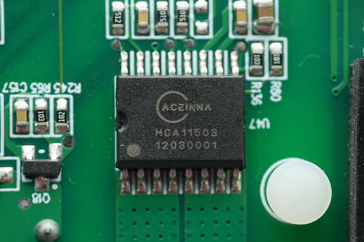
The current sensor is from ACEINNA, marked with MCA11503, model MCA1101-50-3. It is an isolated current sensor chip with a ±50A range, supports a 1.5 MHz bandwidth, operates at a supply voltage of 3.3V, and comes in an SOIC16 package.
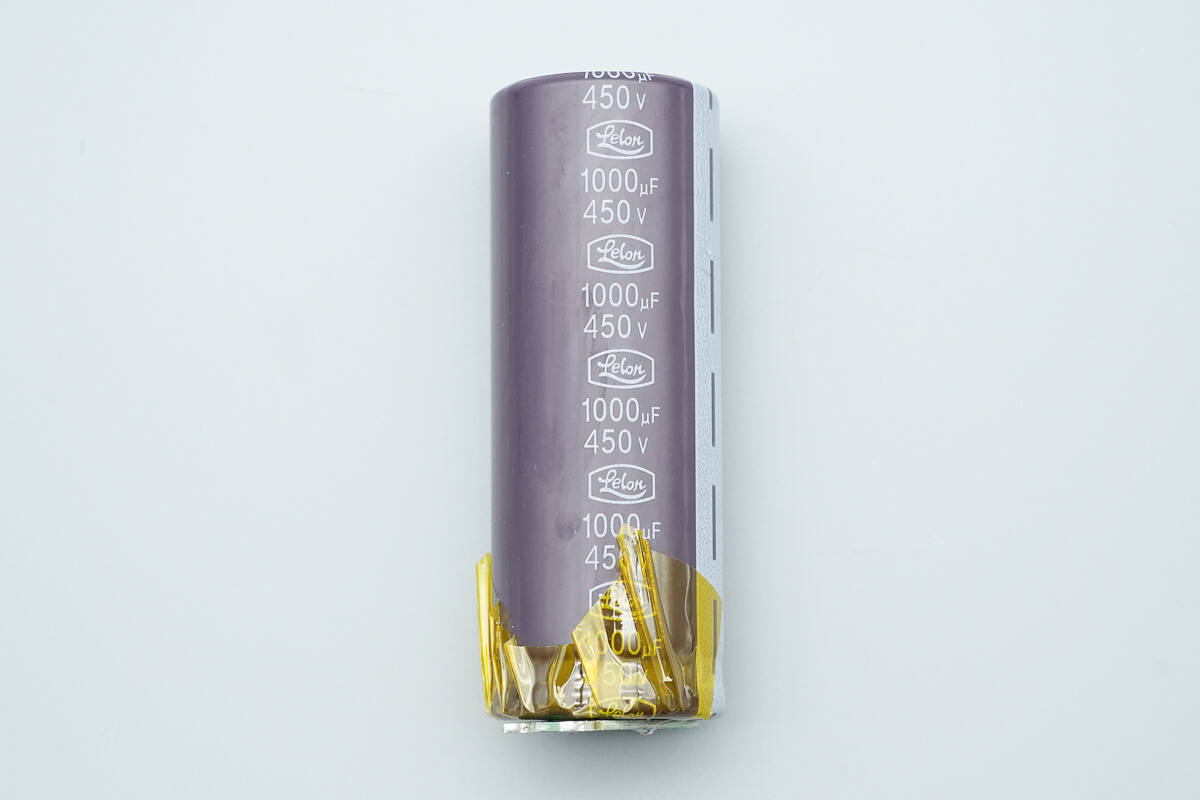
The high-voltage filter capacitor is from Lelon, part of the LSG series. It is rated for 105°C operating temperature and has a 2000-hour lifespan guarantee, with a specification of 1000 μF, 450 V.
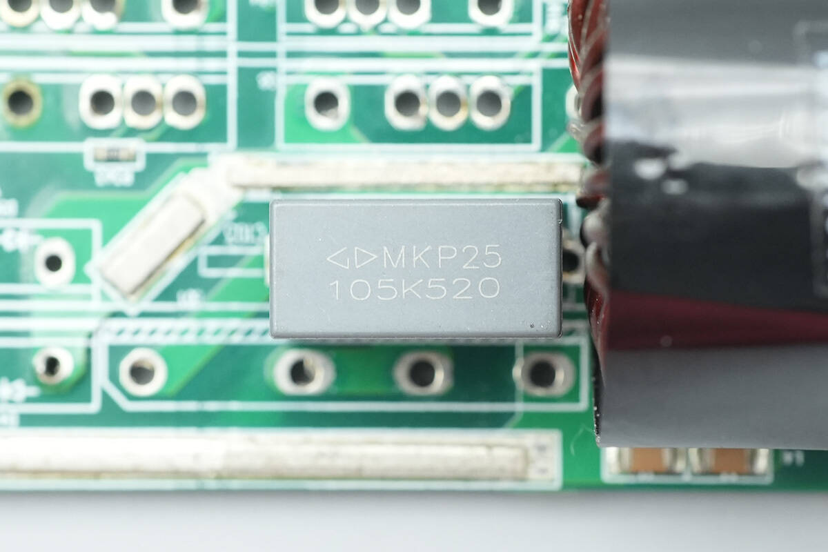
The film filter capacitor has a specification of 1 μF, 520 V.
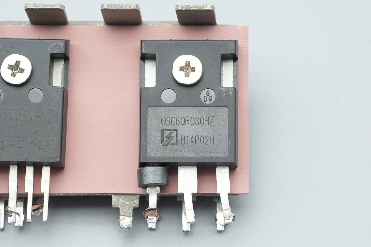
The LLC MOSFET is from Oriental, model OSG60R030HZF. It is an NMOS transistor with a voltage rating of 650 V, an Rds(on) of 30 mΩ, and comes in a TO247 package.
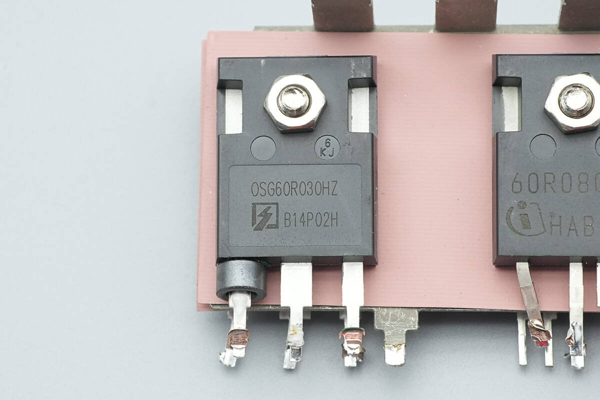
The other LLC MOSFET has the same model.
The third LLC MOSFET has the same model.
A total of four OSG60R030HZF MOSFETs are used.
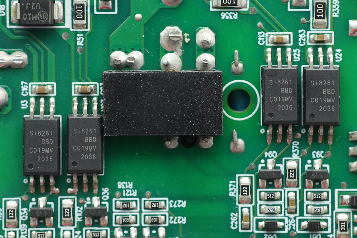
The four isolation drivers correspond to the four LLC MOSFETs.
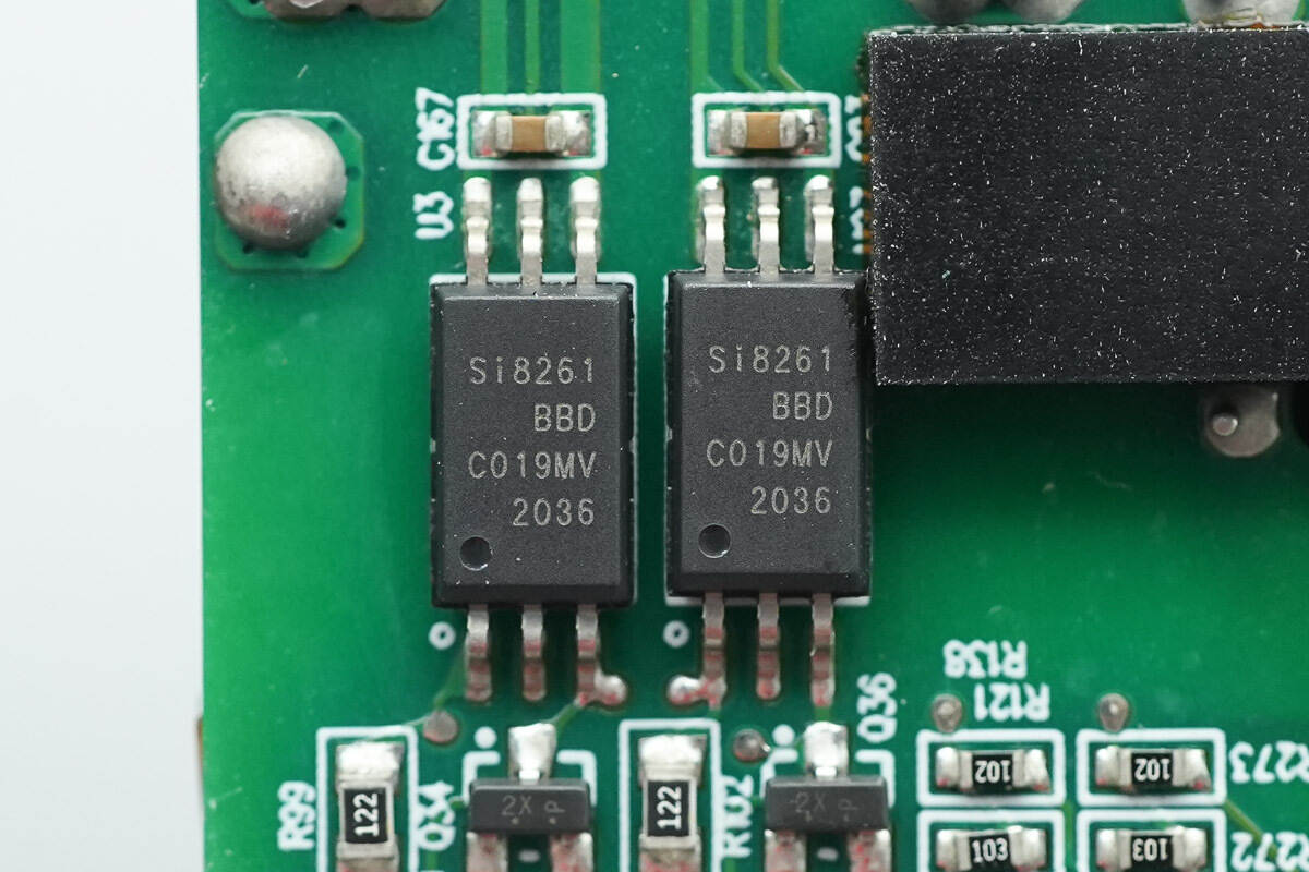
The isolation drivers are SKYWORKS Si8261BBD-C.
The resonant inductor is tightly insulated with high-temperature tape.
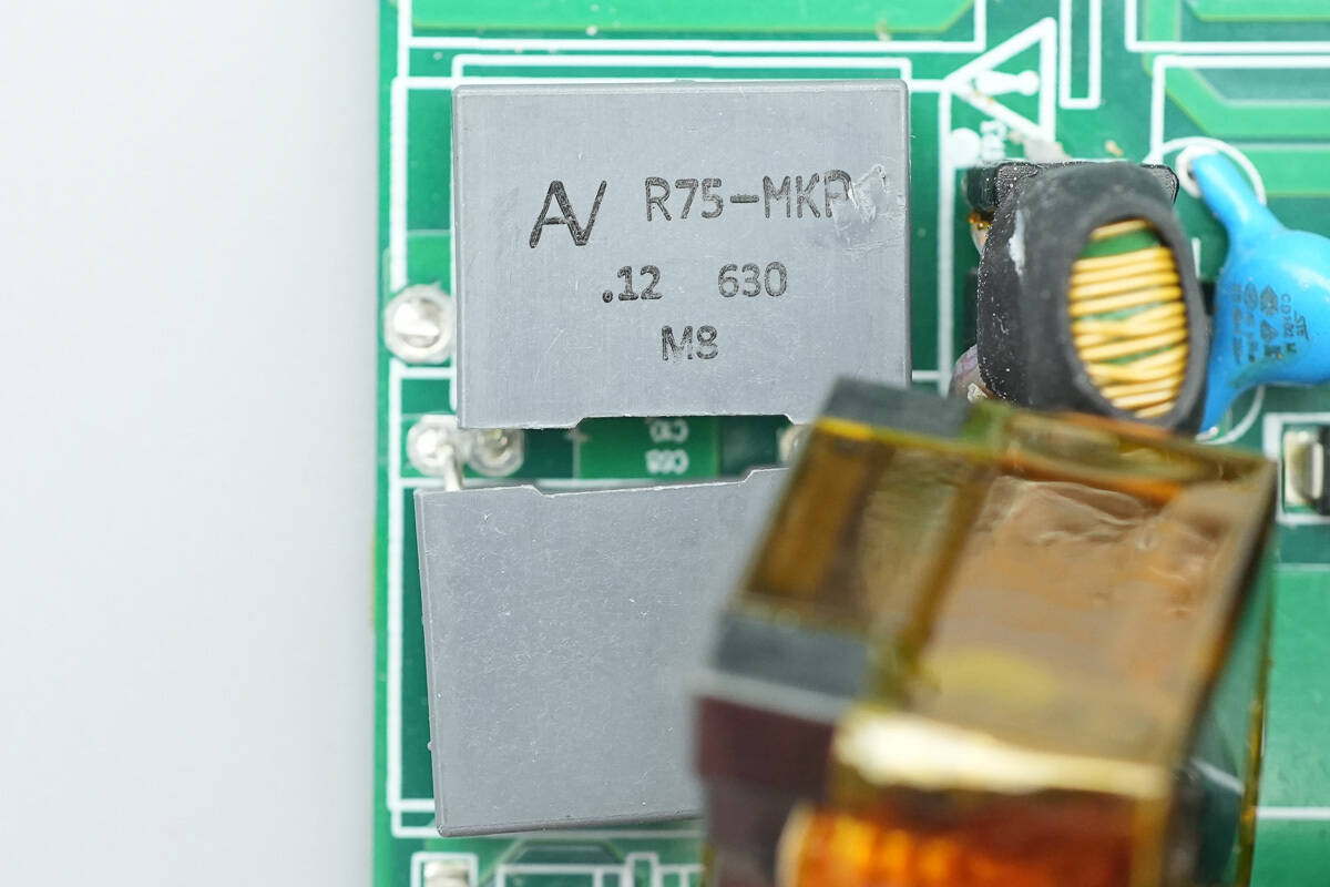
The resonant capacitors are rated at 0.12 μF, 630 V, with two capacitors connected in parallel.
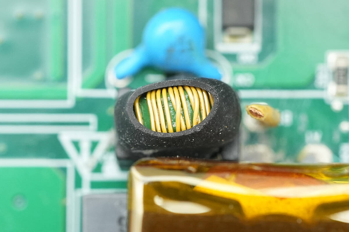
The current transformer is used to monitor the primary current of the transformer.
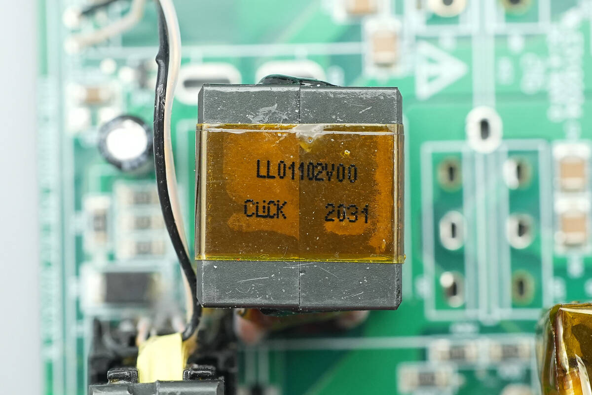
Close-up of the other LLC resonant inductor.
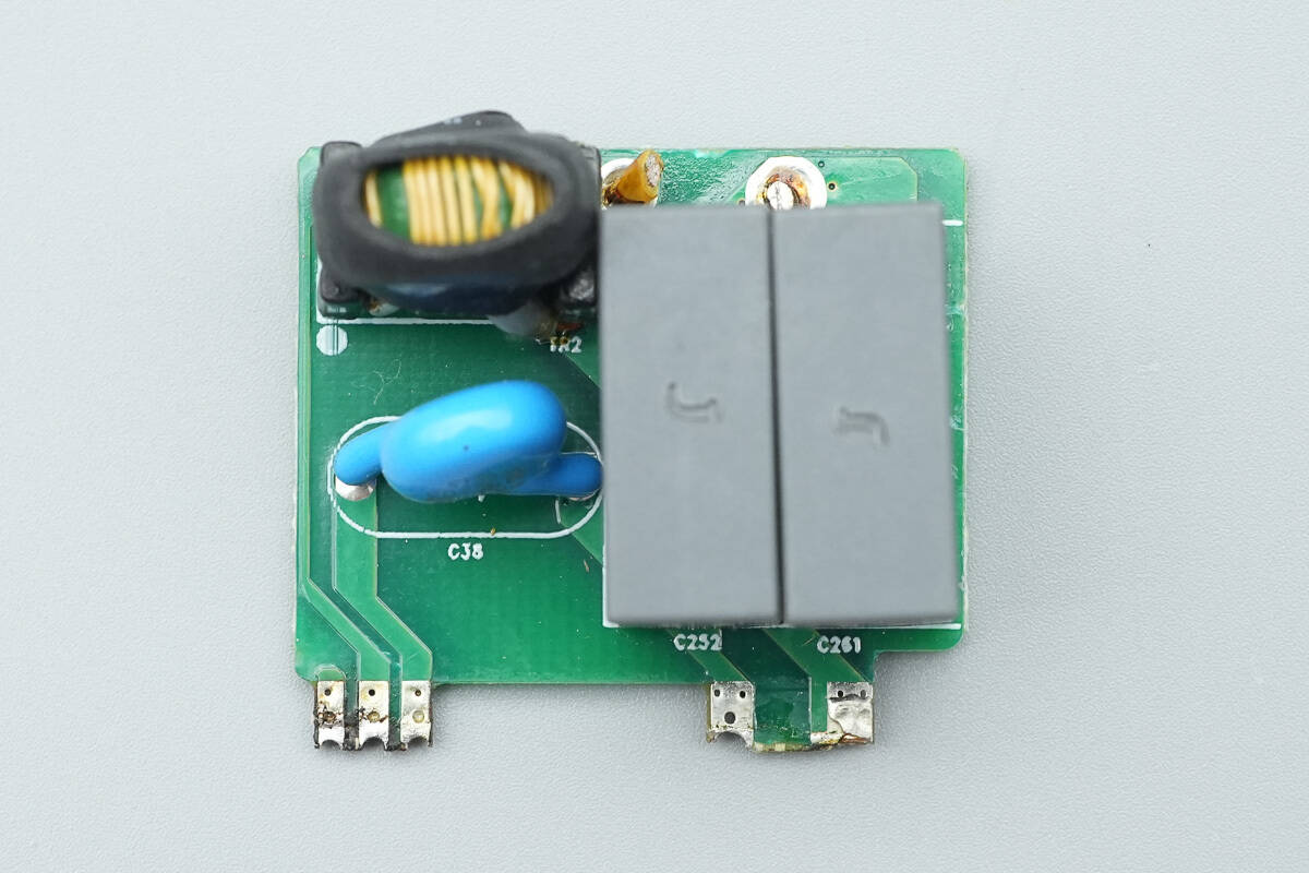
The resonant capacitors and the current transformer are soldered onto a separate small PCB.
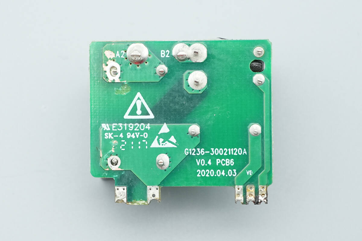
There are no components on the rear side.
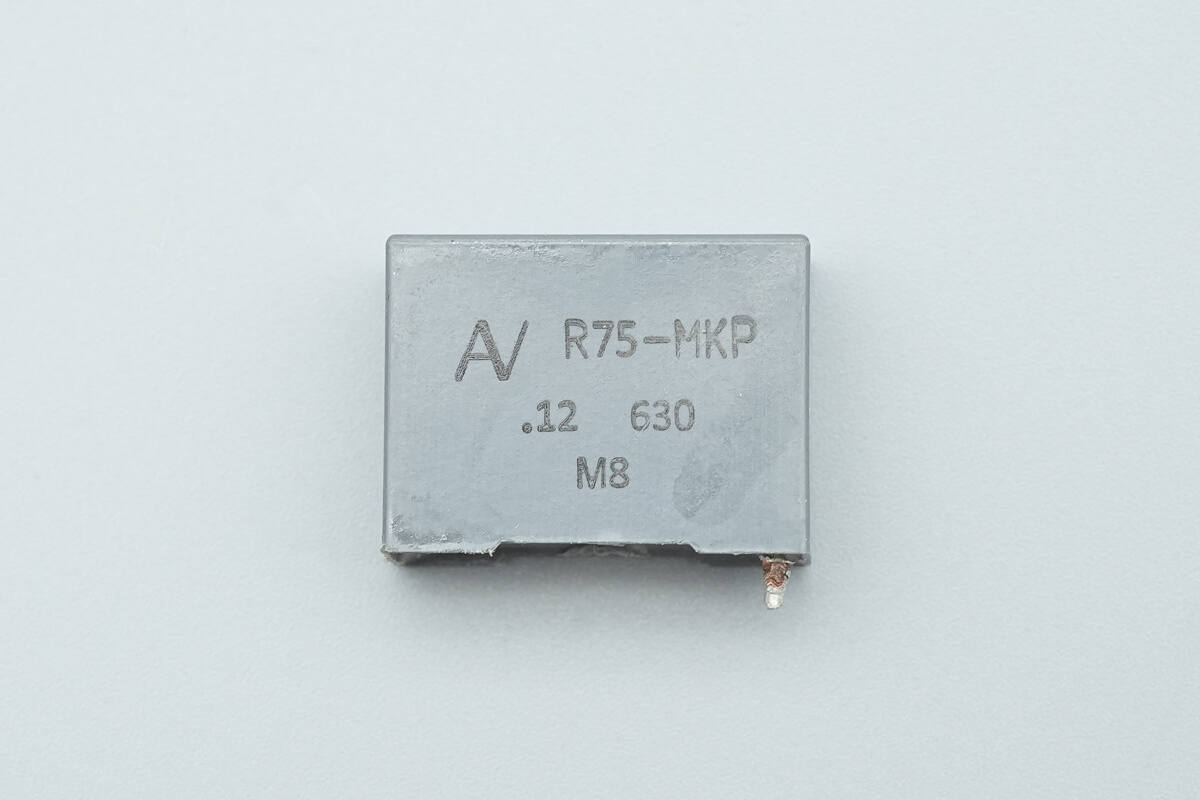
Both resonant capacitors are rated at 0.12 μF, 630 V.
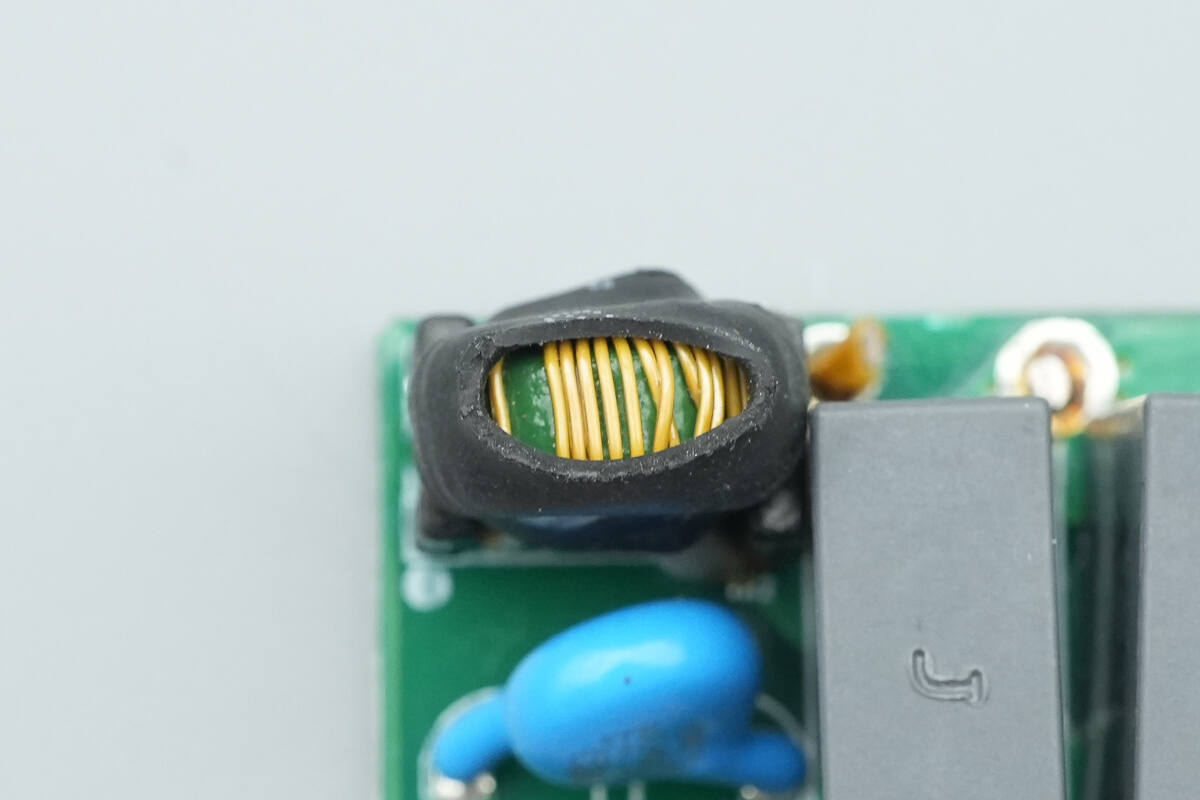
The current transformer is wound with insulated wire and insulated with a heat-shrink tube.
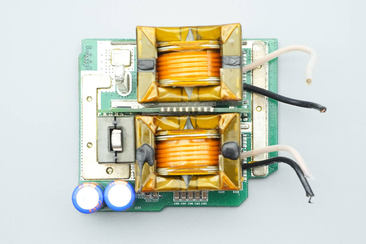
The transformers, filter inductor, and filter capacitors are soldered onto a separate PCB.
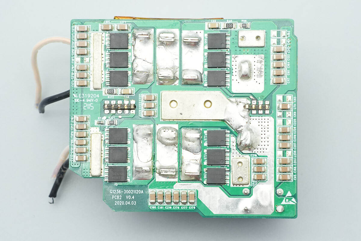
The back has synchronous rectifiers and MLCC capacitors.
Remove the synchronous rectifier drive PCB.
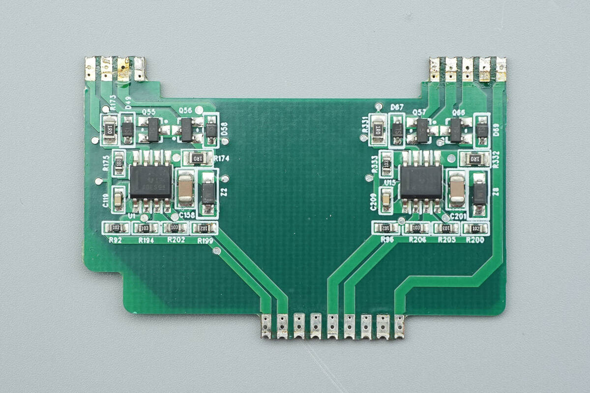
There are two low-side drivers on the front of the PCB.
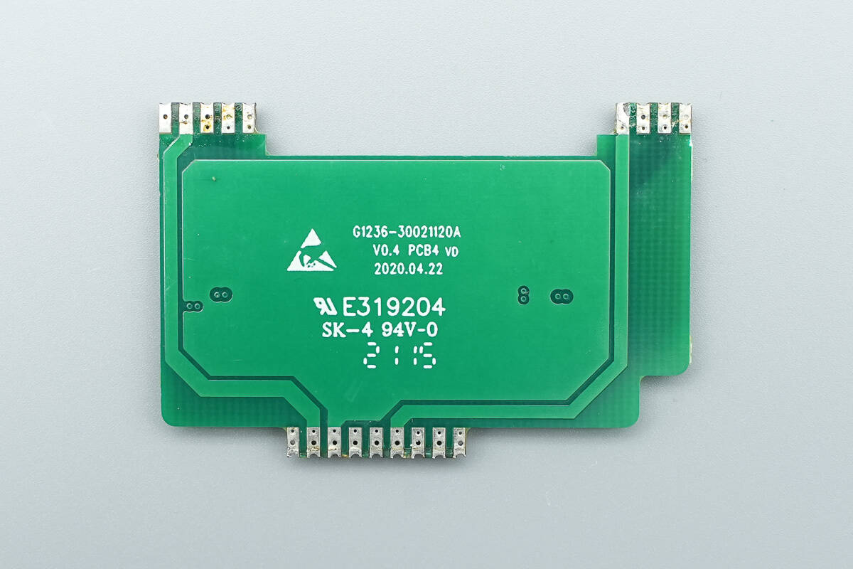
There are no components on the other side.
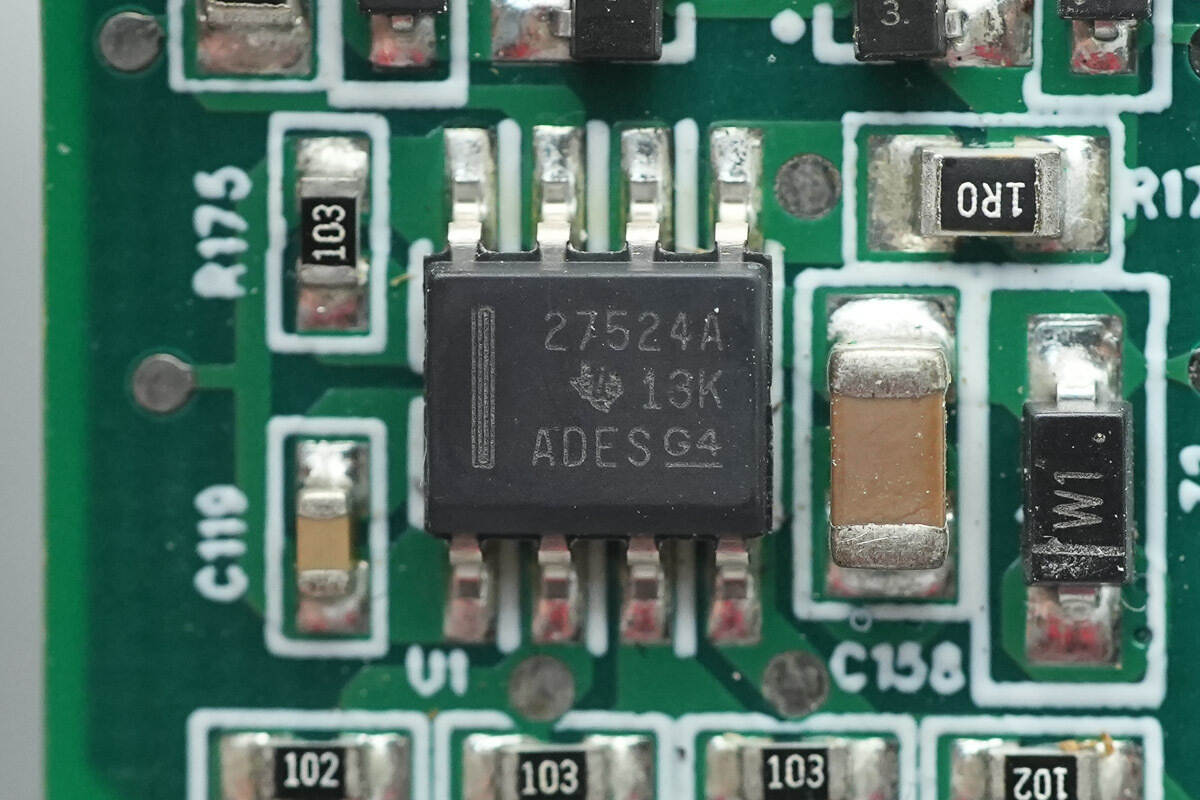
The low-side driver is from the TI model UCC27524A.
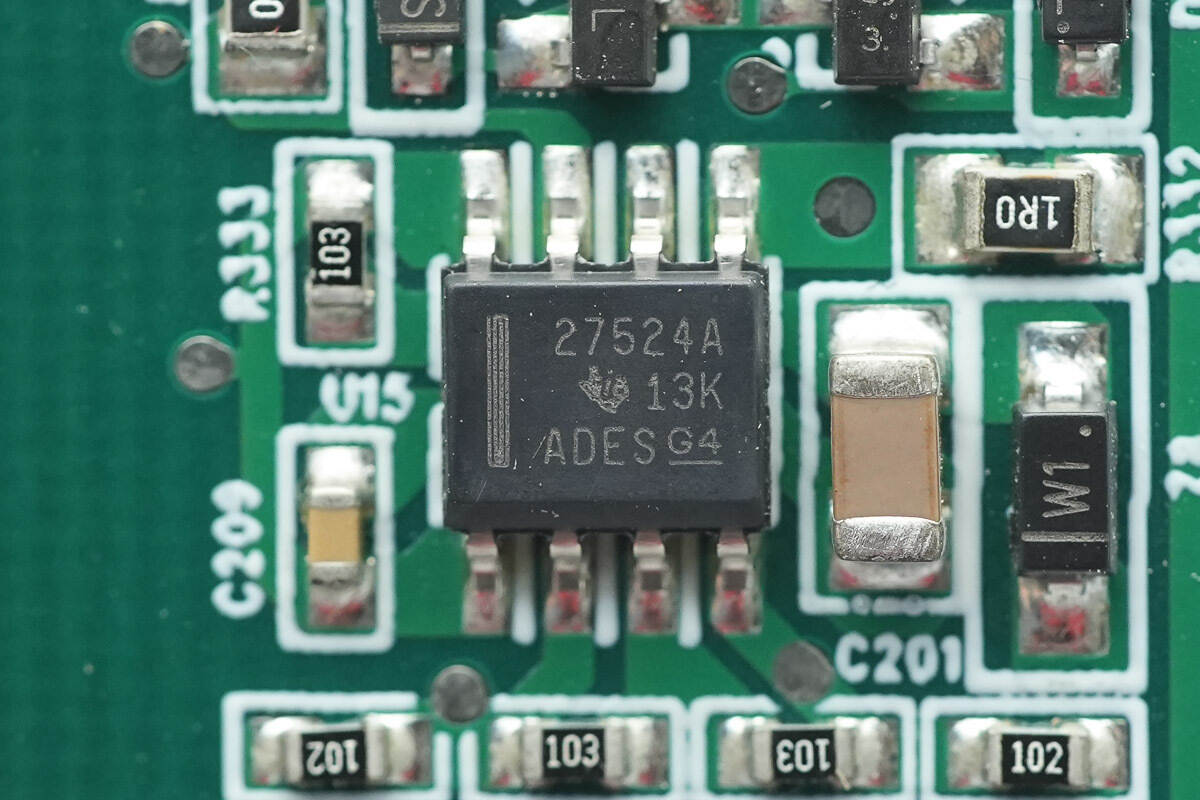
The other low-side driver is the same model.
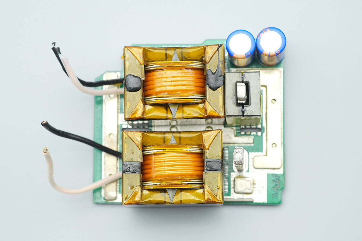
This PCB has LLC transformers, filter capacitors, and a filter inductor.

The primary winding of the transformer is made of insulated wire, the secondary winding is made of welded copper sheets, and the magnetic core is insulated with high-temperature tape.
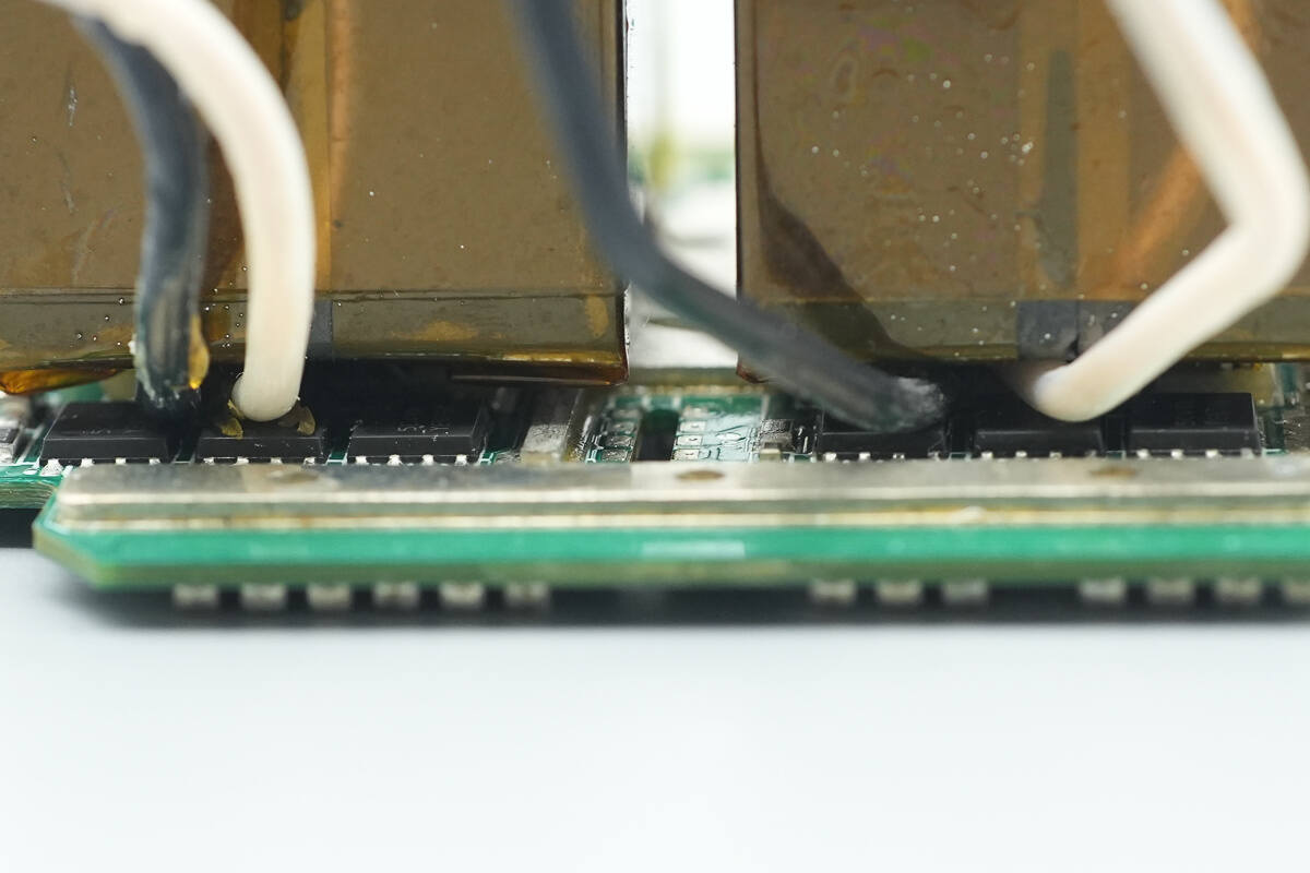
There are synchronous rectifiers below the transformer.
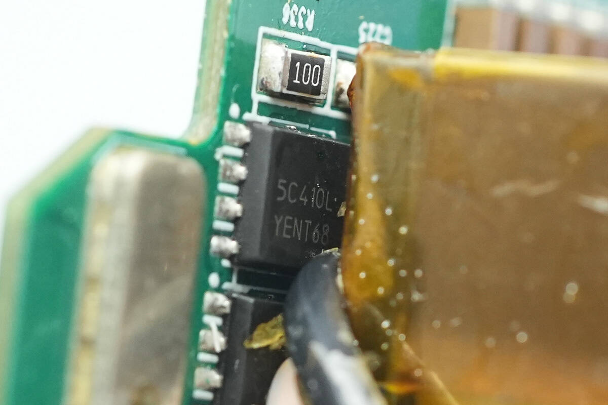
The synchronous rectifier is from Onsemi, marked with 5C410L, model number NTMFS5C410NL, NMOS, rated at 40V, with an on-resistance of 0.82mΩ, and packaged in DFN5.
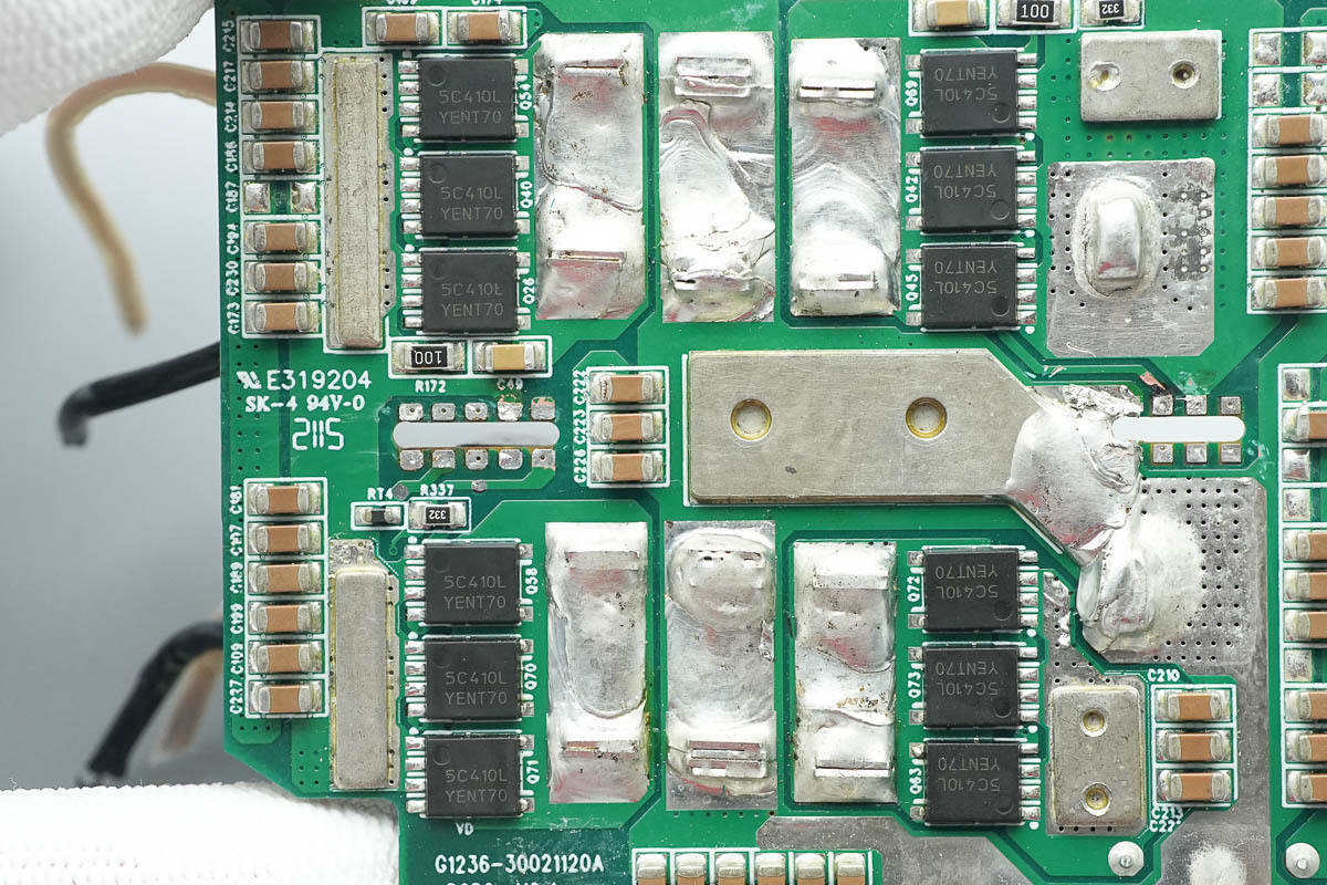
There are 12 identical synchronous rectifiers on the back.
Close-up of the output filter inductor.
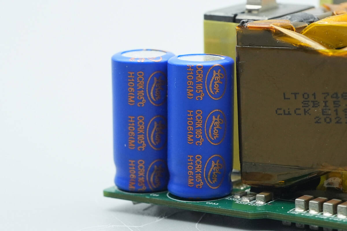
The output filter capacitors are from Lelon and are an OCRK polymer solid aluminum electrolytic capacitor with a lifespan of 5000 hours.
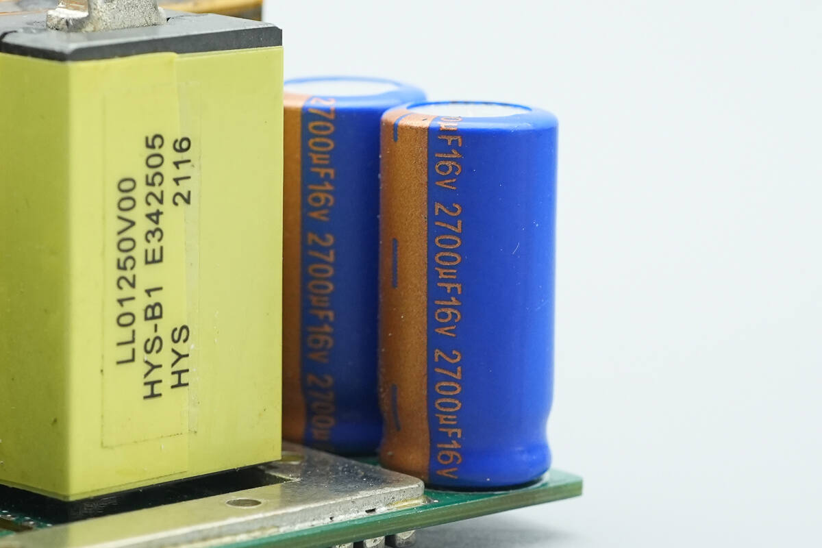
The specification is 2700μF 16V.
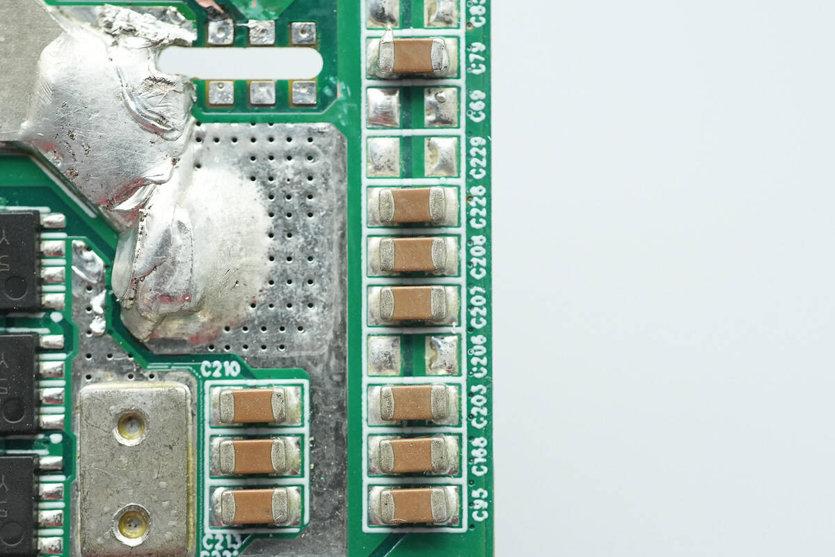
Multiple MLCC capacitors are installed on the back for filtering.
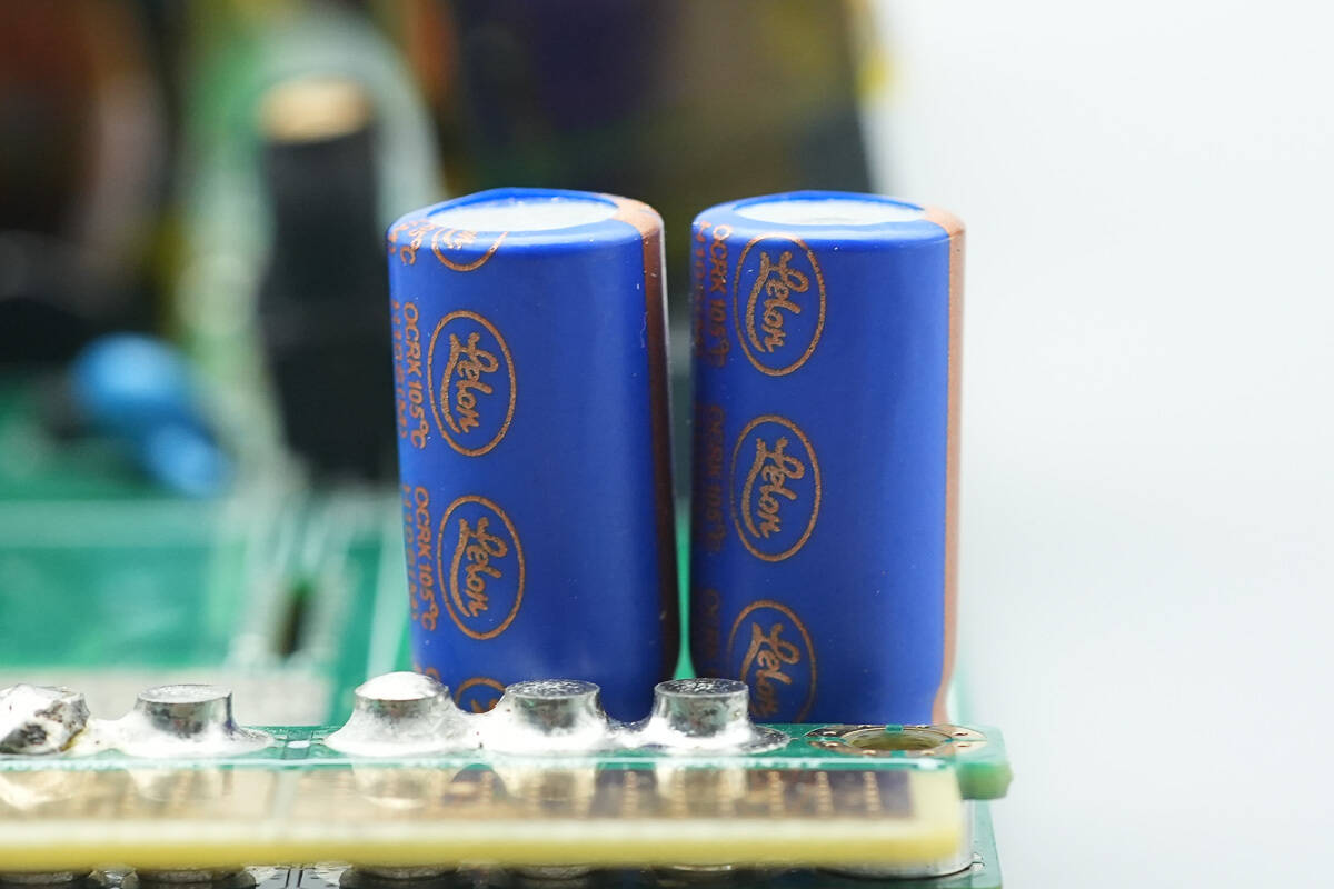
The output filter capacitors are from Lelon.
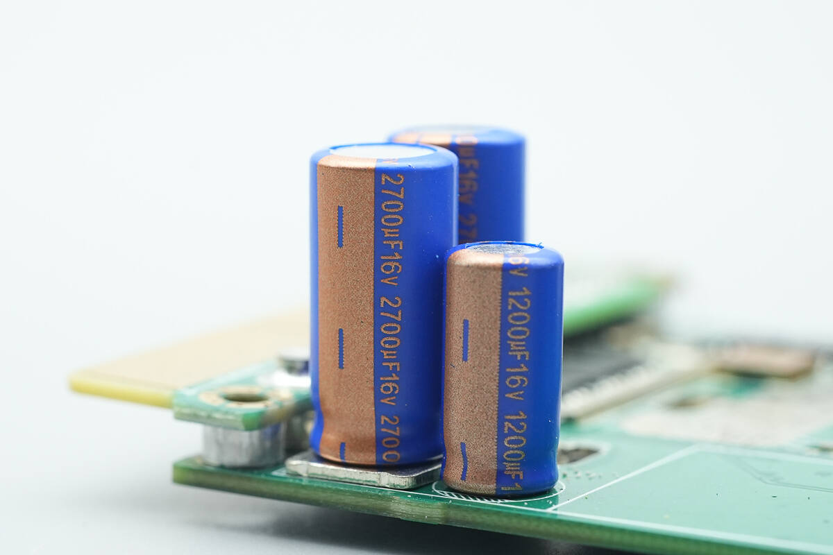
The two filter capacitors are rated at 2700μF 16V.
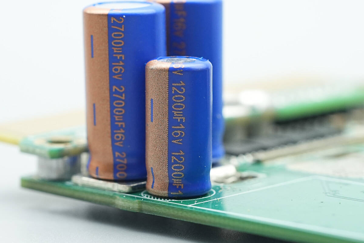
The other capacitor is rated at 1200μF 16V.
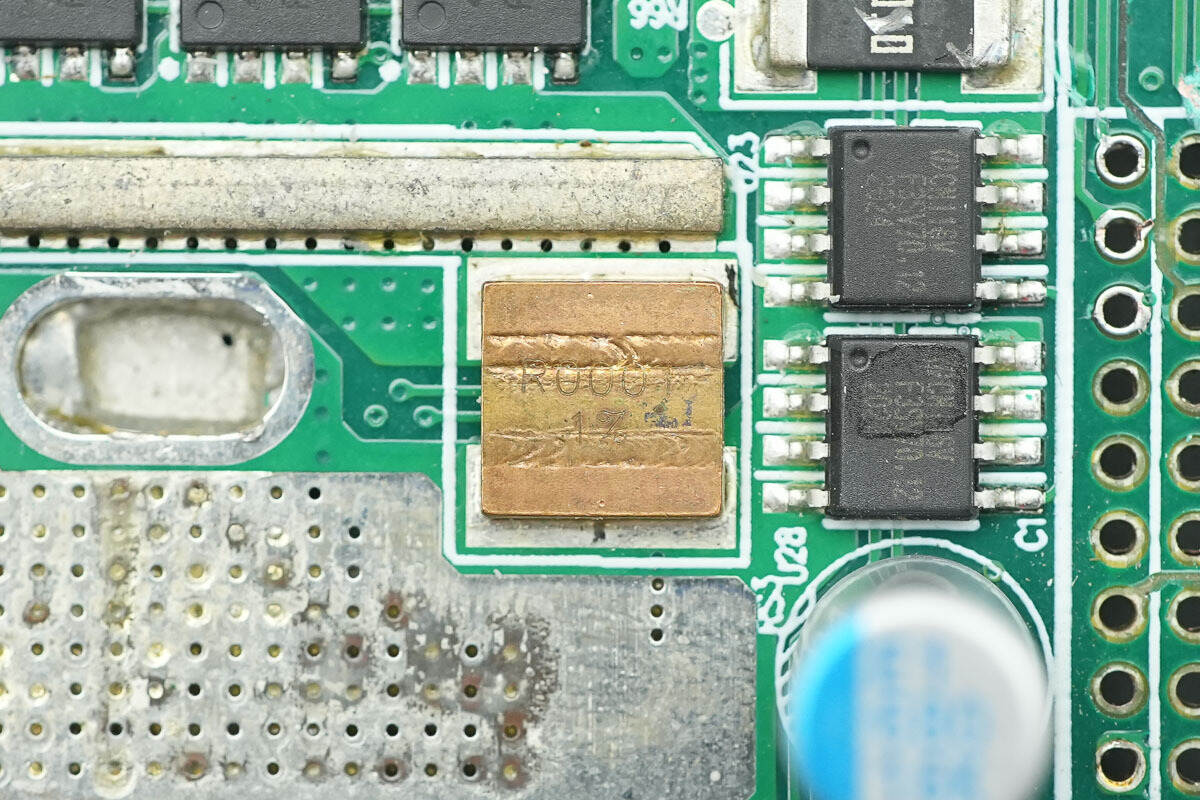
The output current sampling resistor is specified as 0.1mΩ.
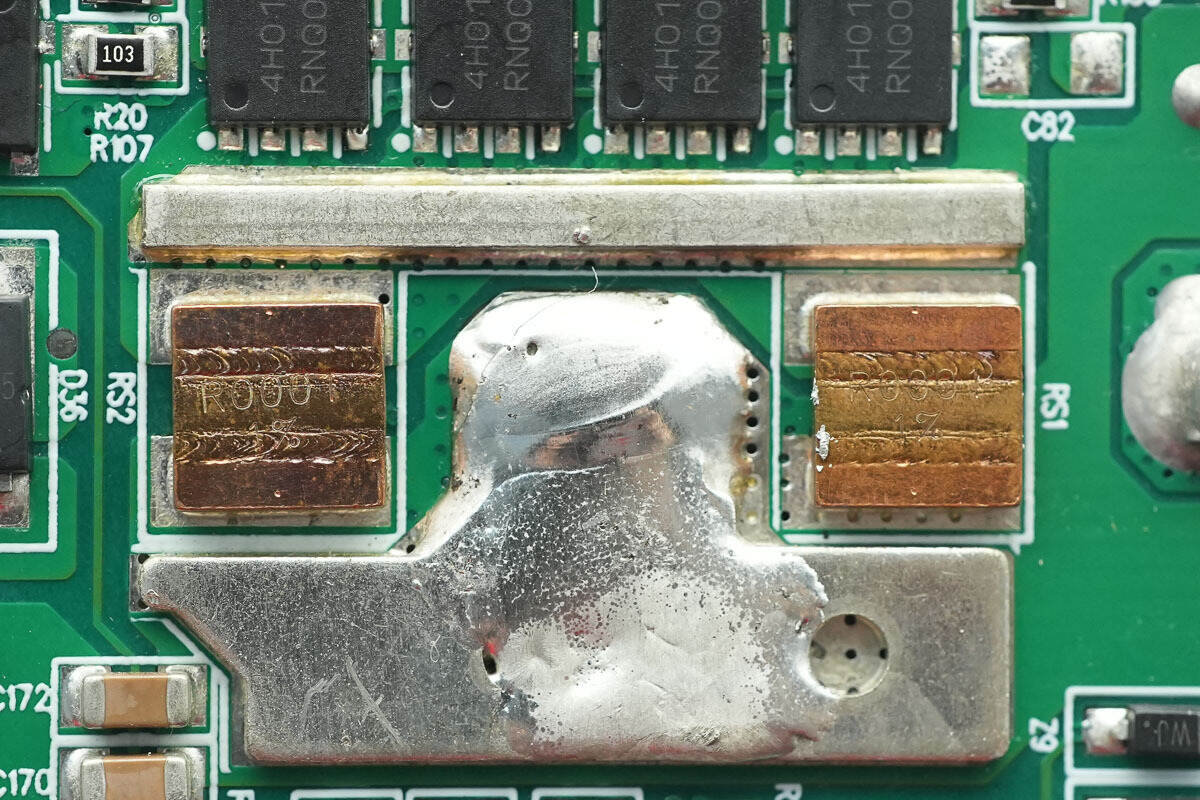
The other two current sampling resistors have the same specifications.
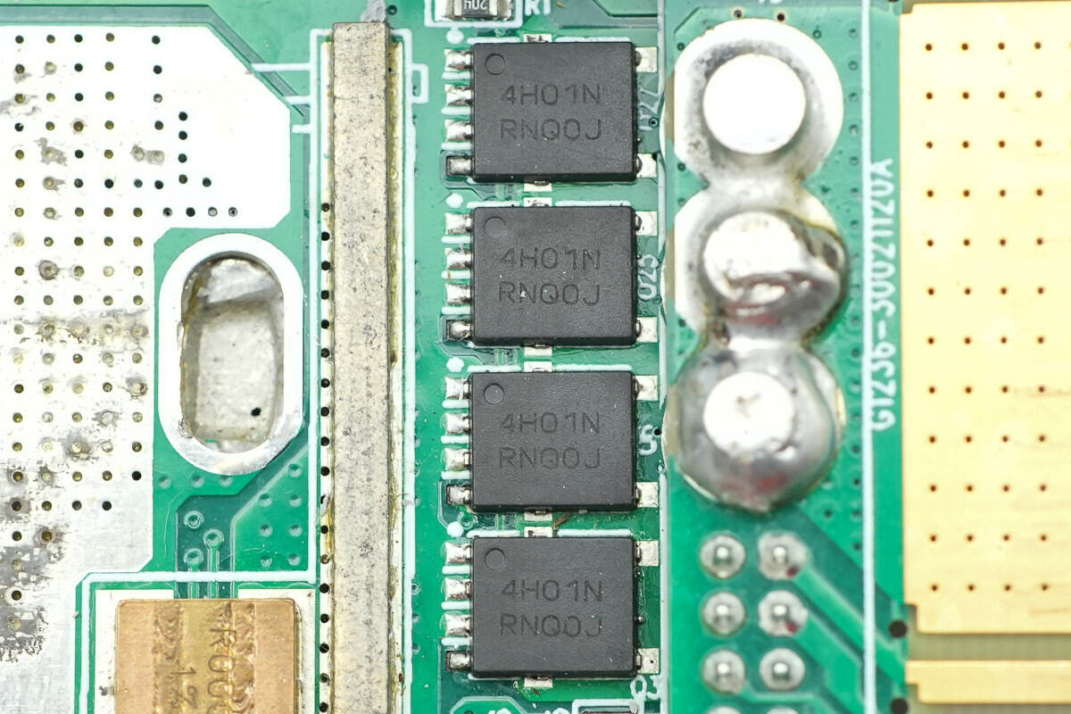
The MOSFETs used for output control are from Onsemi, model NTMFS4H01N, NMOS, with a voltage rating of 25V, an on-resistance of 0.7mΩ, and a DFN5 package.
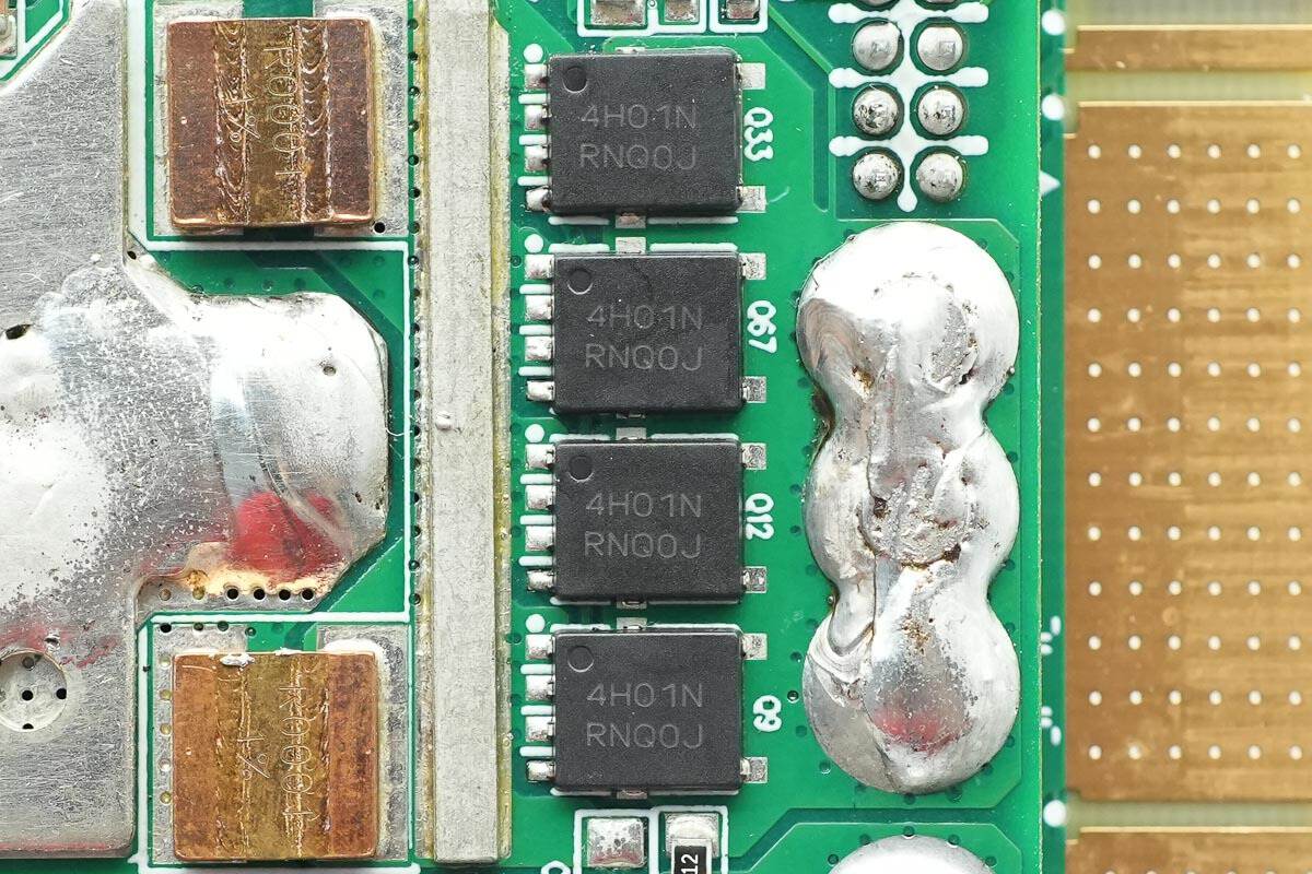
The back also features four identical MOSFETs.
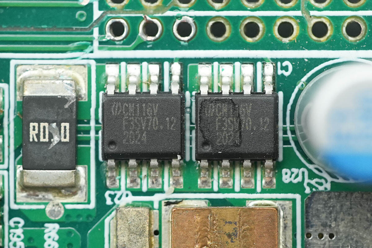
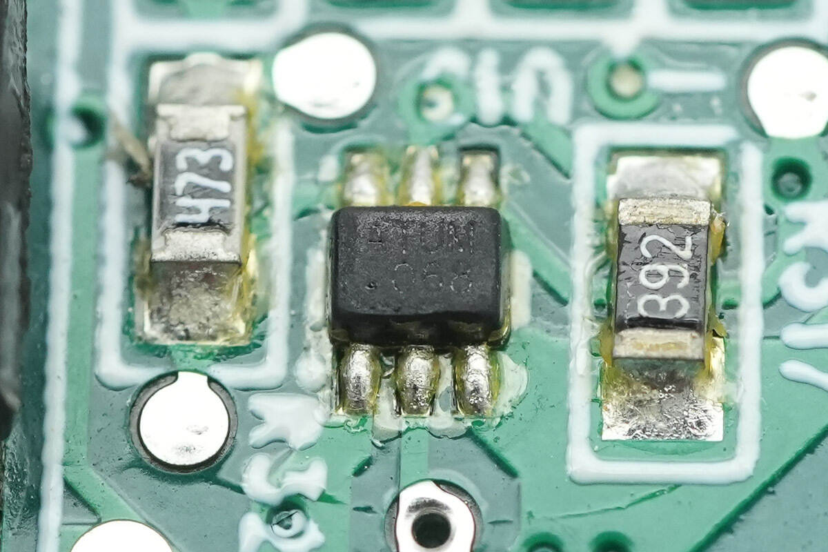
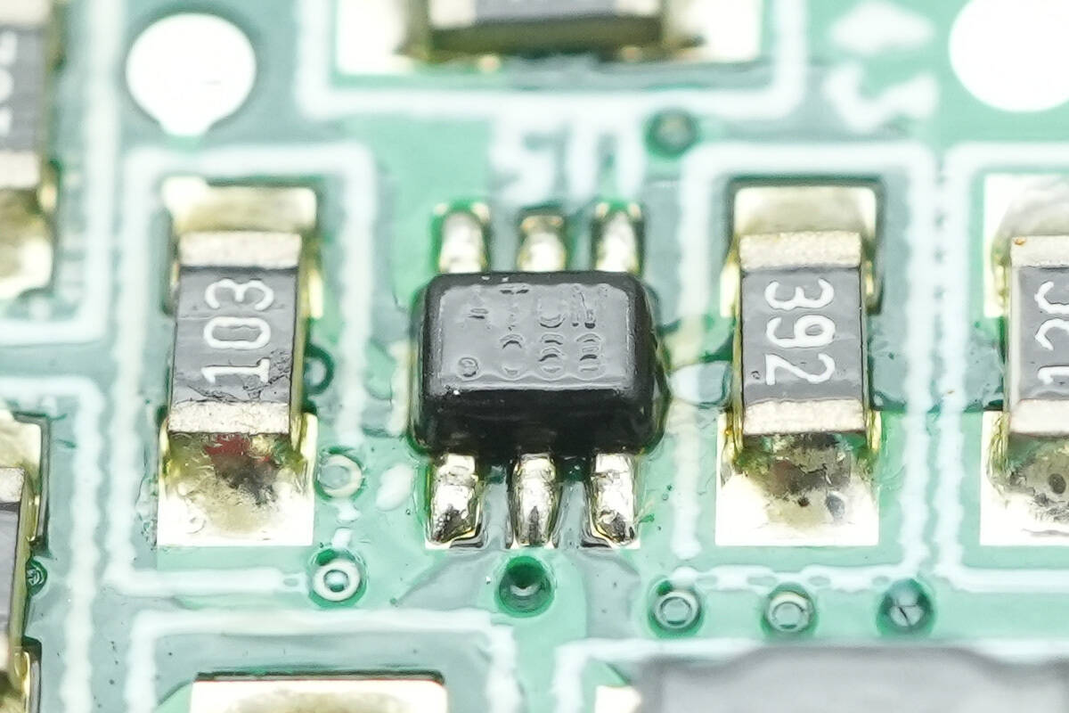
The power-switching chip is a CHAMPION CM11.6V model. It is used to switch between the main and standby power supplies. The chip features a low Rds(on) MOSFET, supports 2 A current, and includes current limiting, over-temperature protection, and short-circuit protection functions. It comes in an SOP-8 package.
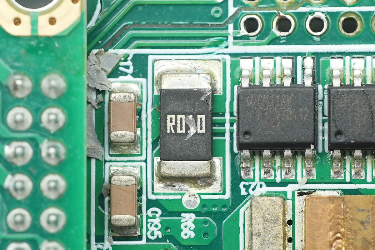
Close-up of the 10mΩ current sampling resistor.
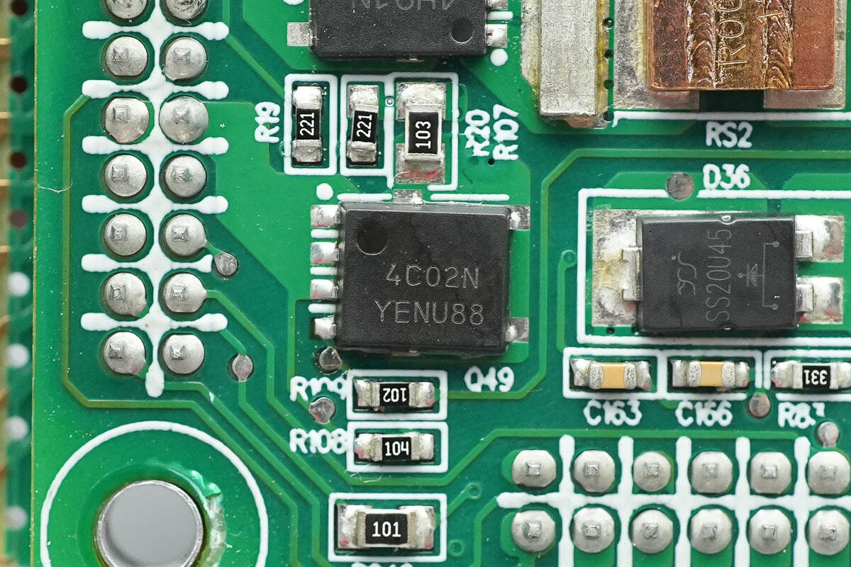
The switching MOSFET is from Onsemi, marked with 4C02N, model NVMFS4C302N, NMOS, with a withstand voltage of 30V, on-resistance of 1.15mΩ, and a DFN5 package.
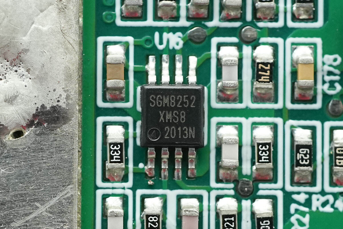
The op-amp is from SGMICRO, model SGM8252, which is a high-precision, low-noise rail-to-rail output operational amplifier in an MSOP-8 package.
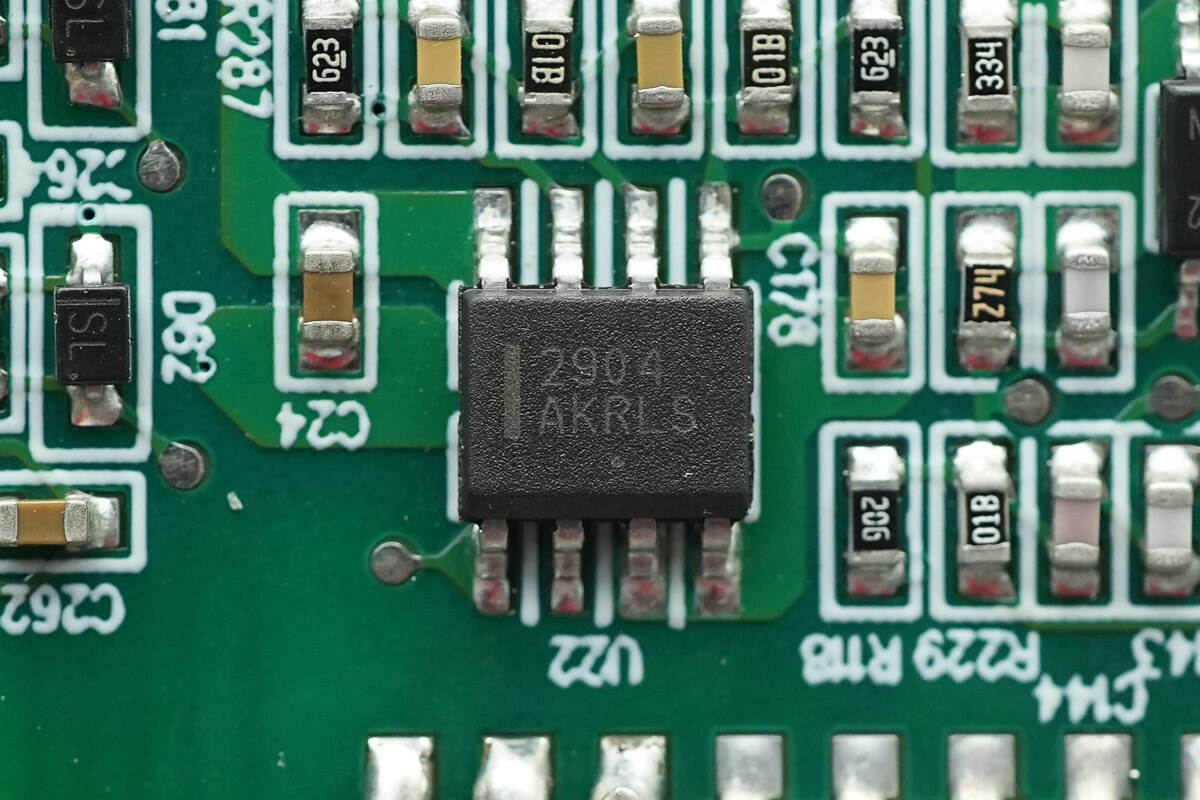
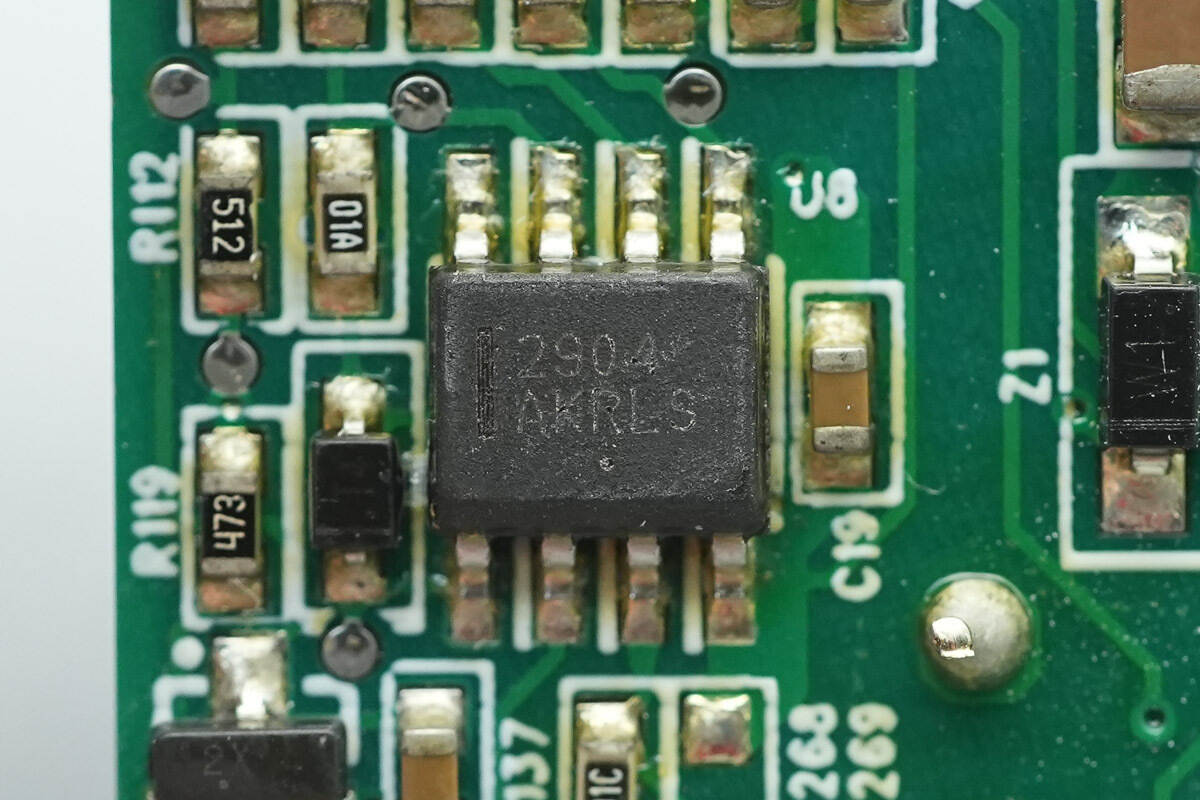
The op-amp is from Onsemi, model LM2904, which is a low-power dual op-amp in an SOIC-8 package.
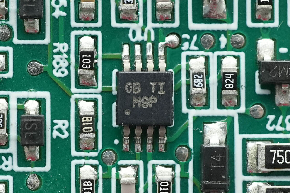
The voltage comparator is from TI, marked with M9P, model LM393, and is a dual-channel differential comparator in a VSSOP8 package.
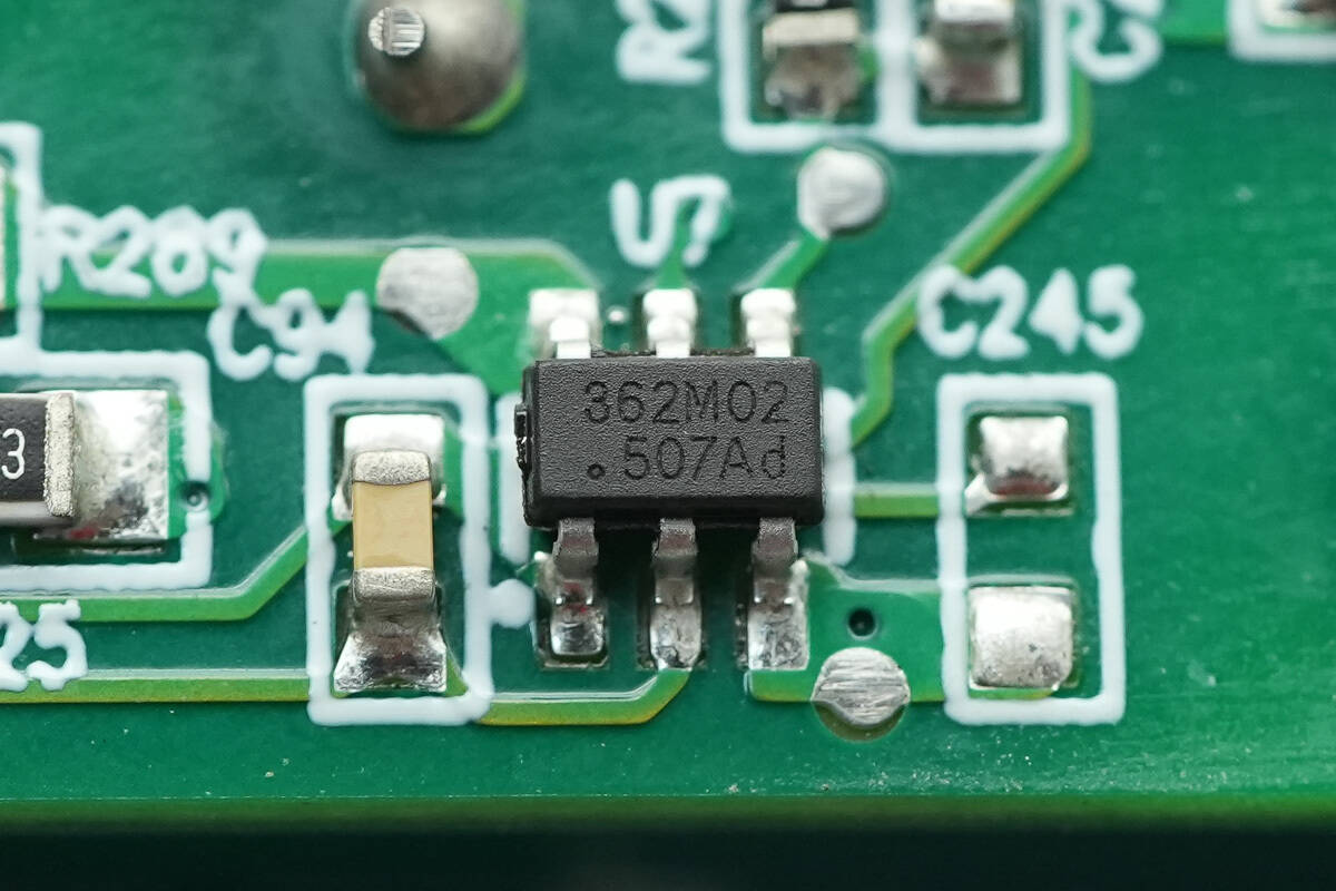
The standby power chip is from On-Bright, model OB2362A. It is a highly integrated current-mode controller with multi-mode operation, low standby power consumption, and an SOT23-6 package.
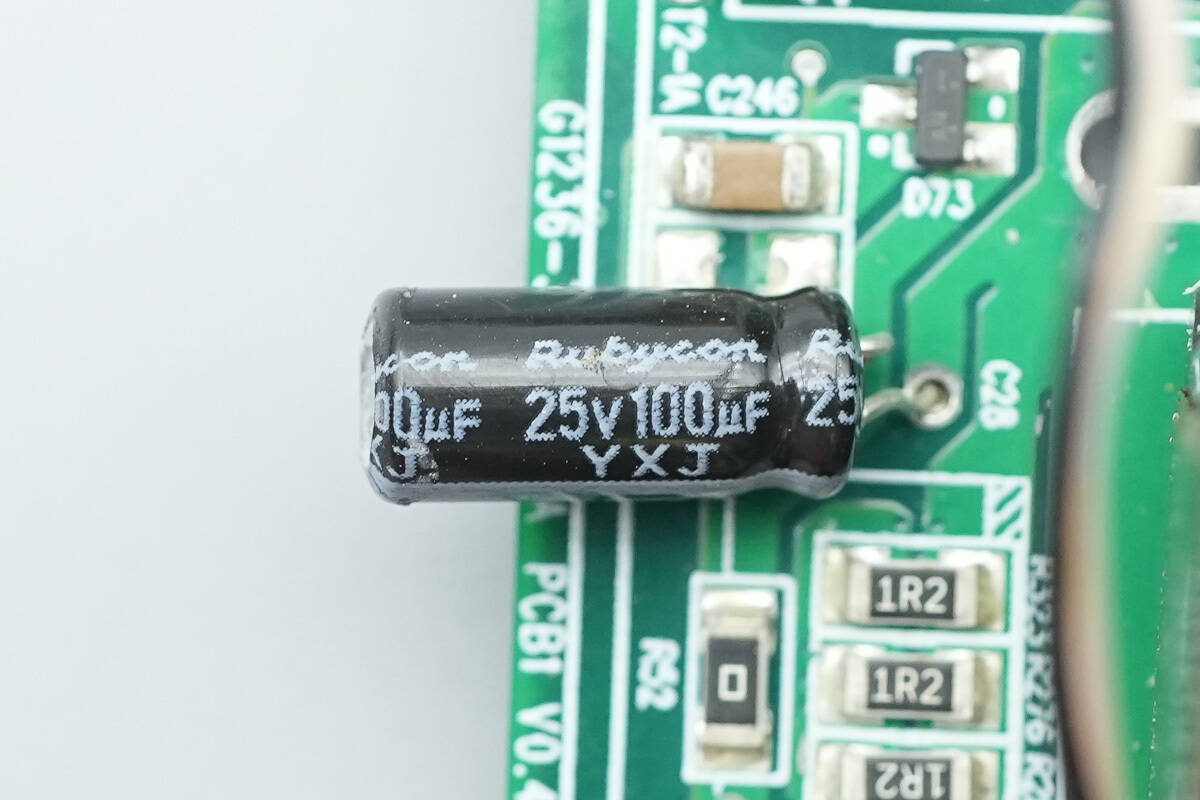
The power supply capacitor is rated at 25V 100μF.
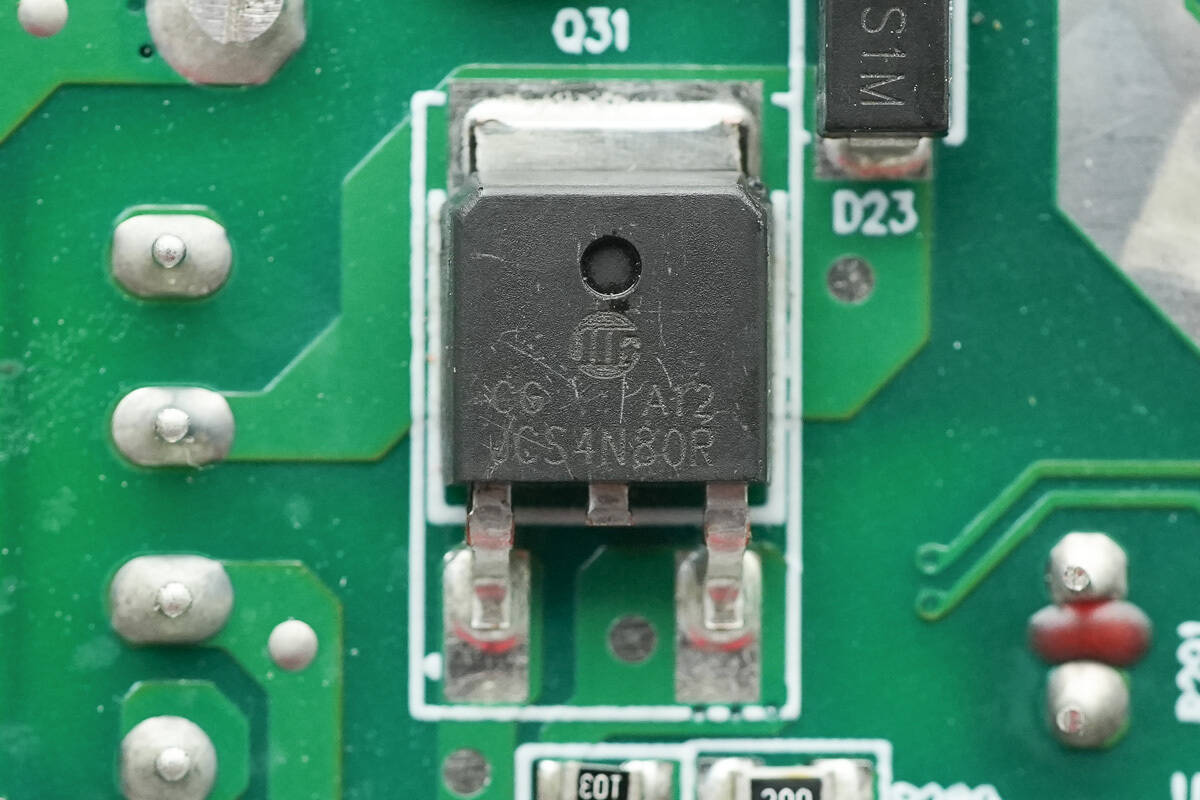
The MOSFET is from HWDZ, model JCS4N80R, an NMOS with a withstand voltage of 800V, an on-resistance of 2.6Ω, and a DPAK package.
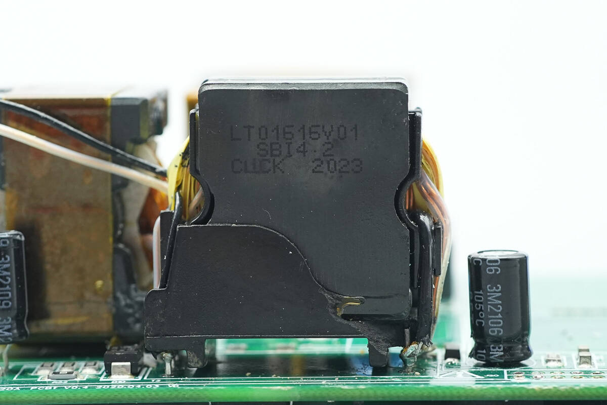
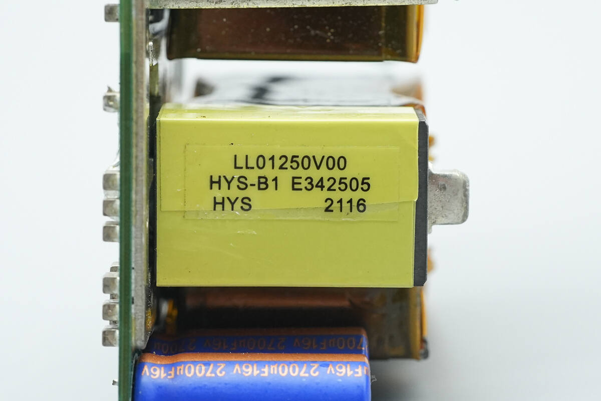
The standby power transformer has a plastic casing for insulation at the bottom.
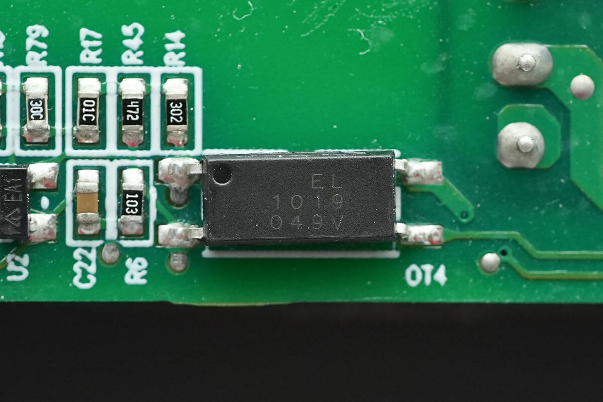
The Everlight EL1019 optocoupler is used for output voltage feedback.
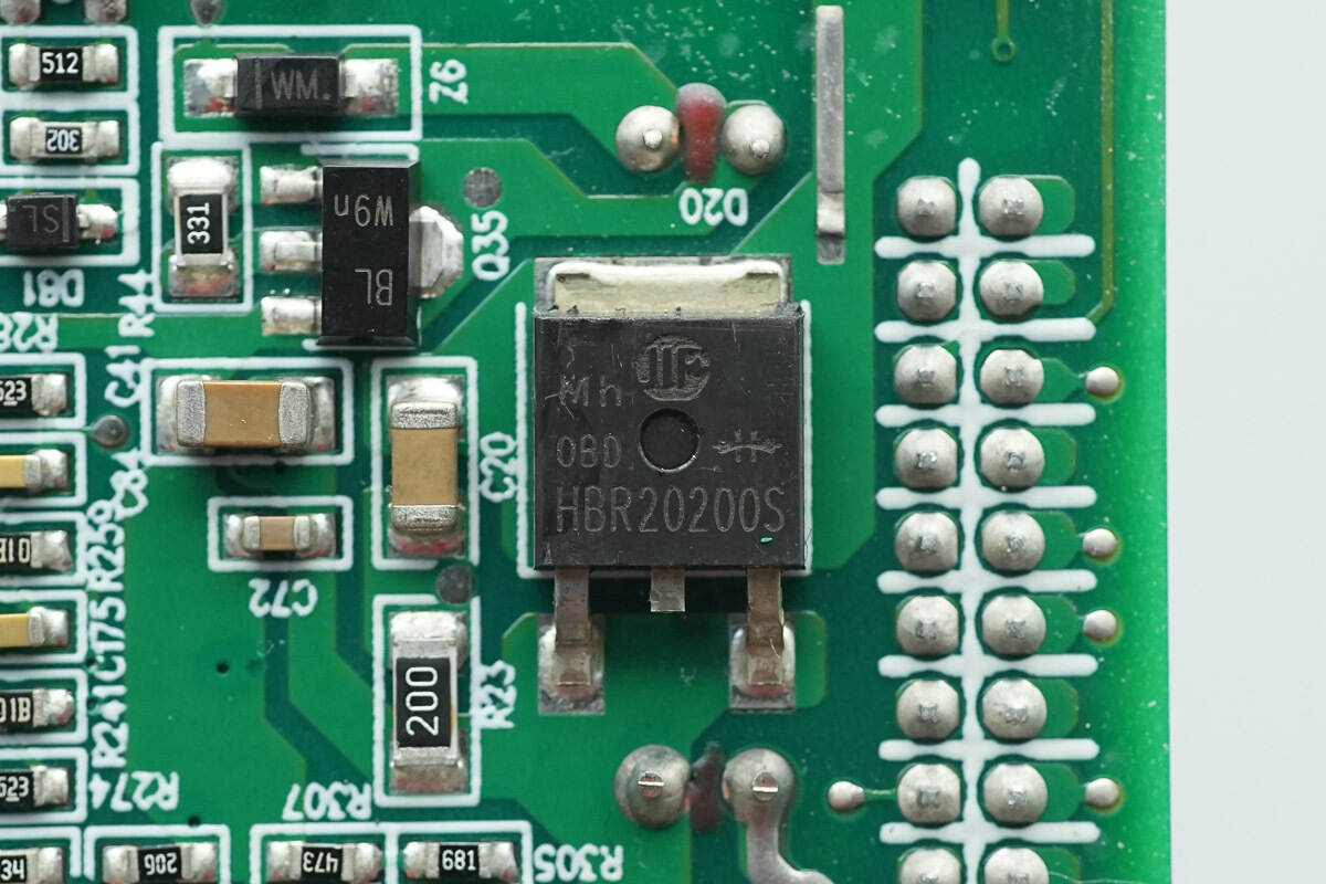
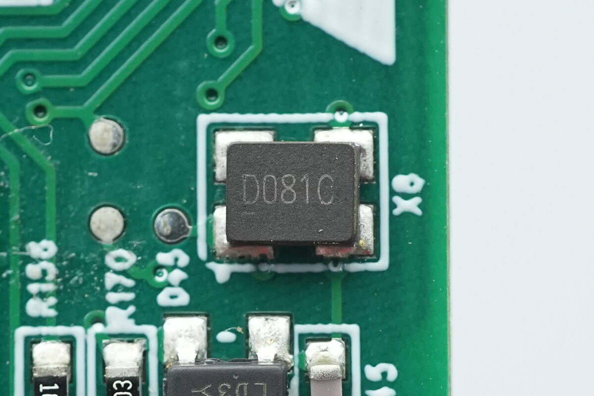
The Schottky diode is from HWDZ, model HBR20200S, specification 20A200V, and uses the DPAKM package.

The solid capacitors are rated at 680μF 16V, and three are used in parallel.
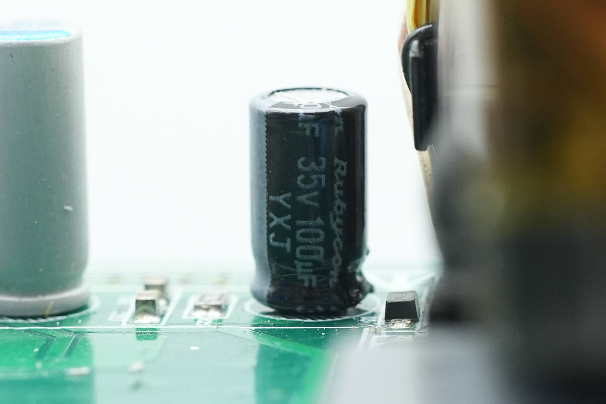
The filter capacitor is from Rubycon and is rated at 35V 100μF.
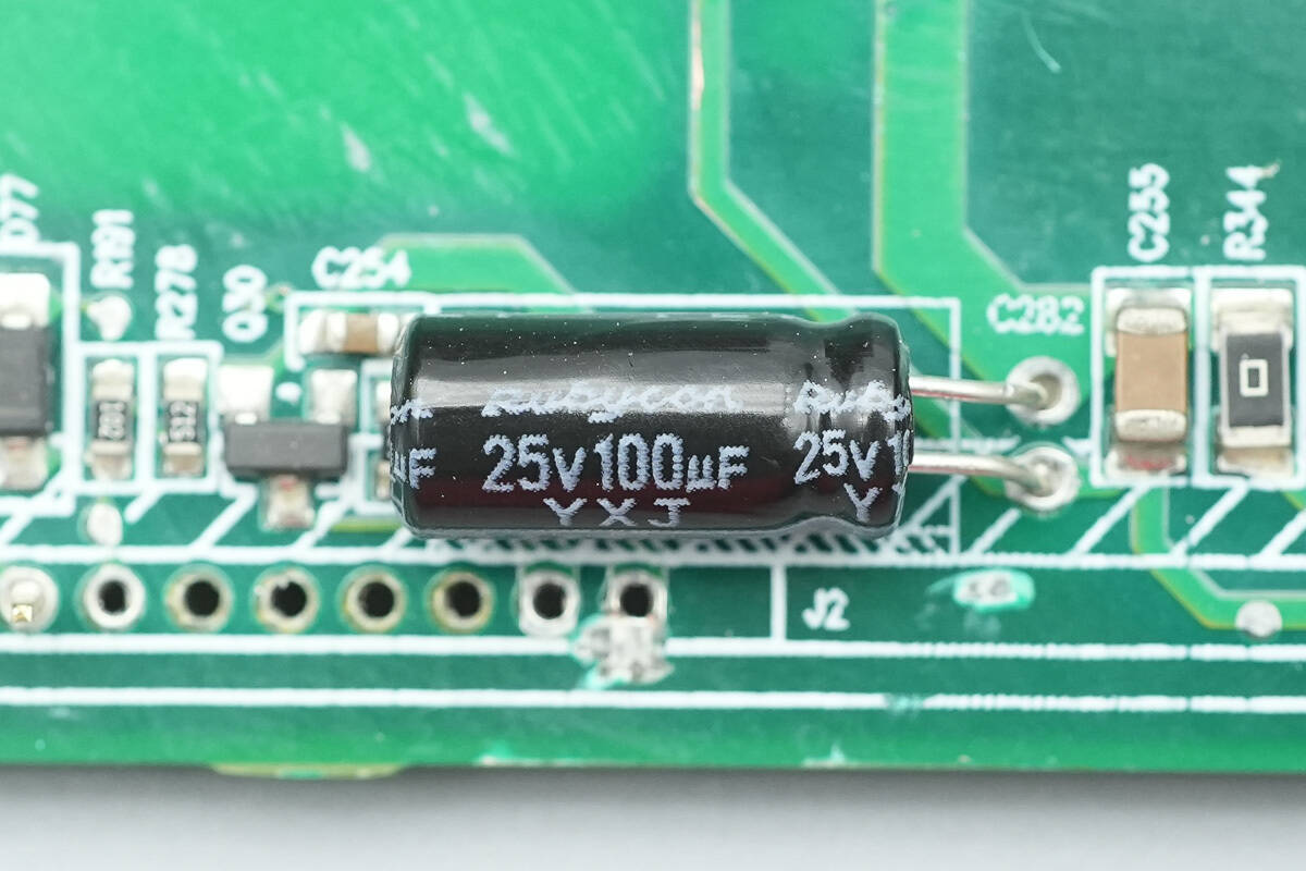
The filter capacitor is rated at 25V 100μF.
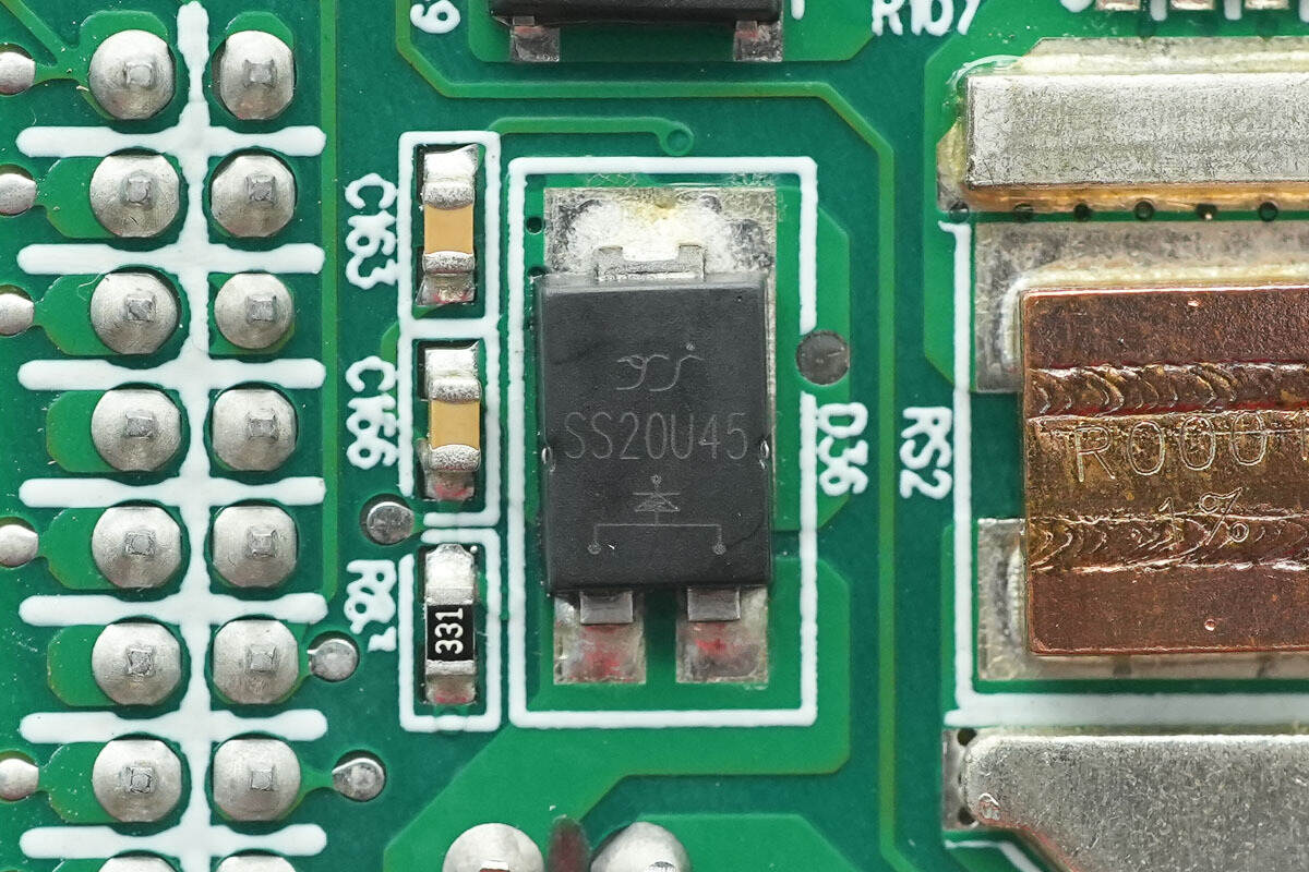
The Schottky diode is from YJ, model SS20U45, specification 45V20A, and uses a TO-277 package.
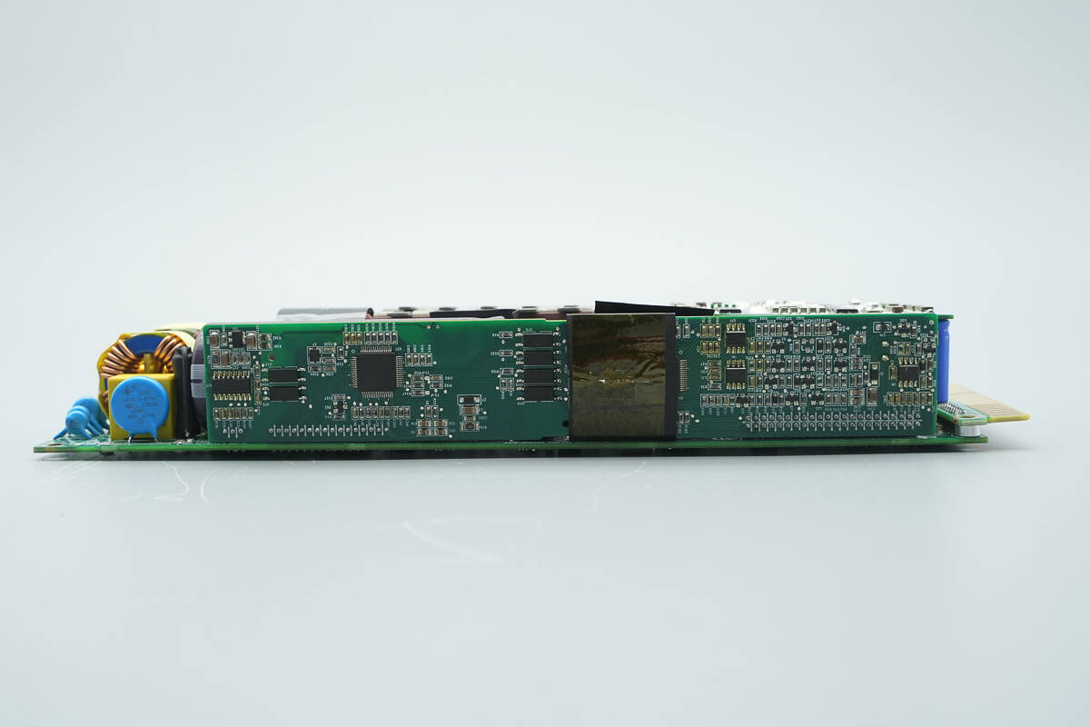
The control PCB includes components such as power detection chips, optocouplers, PFC controller, LLC controller, memories, and operational amplifiers.
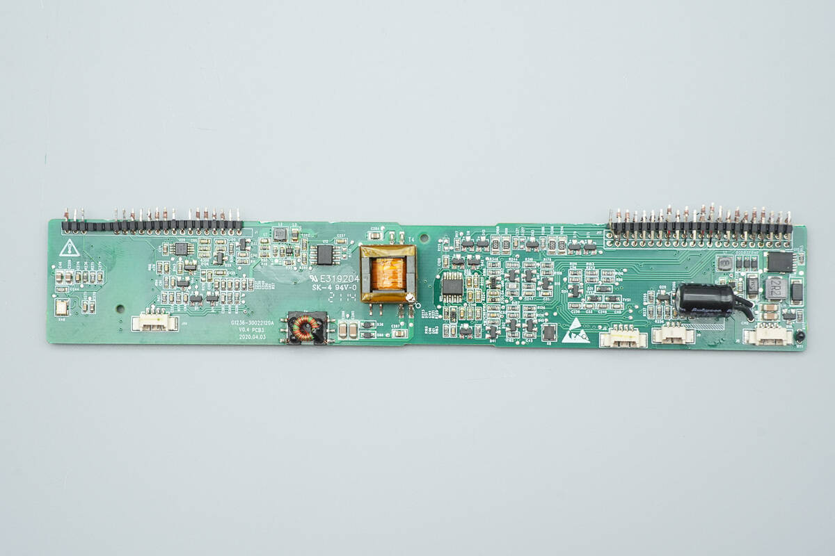
The other side is equipped with operational amplifiers, a synchronous buck converter, a driver, and an isolation transformer.

The power detection chip is from RENERGY, model RN8209C. It supports active power, reactive power, and active and reactive energy measurement. The chip has a built-in three-channel ADC, a UART interface, and a power monitoring function. It is packaged in SOP16L.
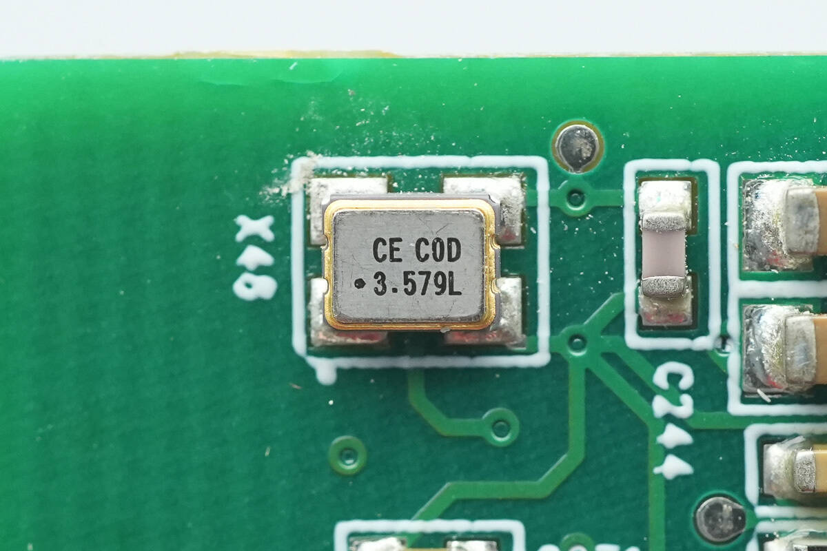
Close-up of the chip's external clock crystal oscillator.
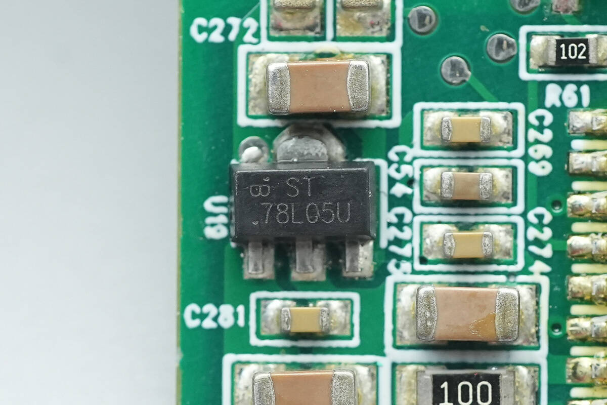
The 78L05U voltage regulator chip supplies power to the chip.
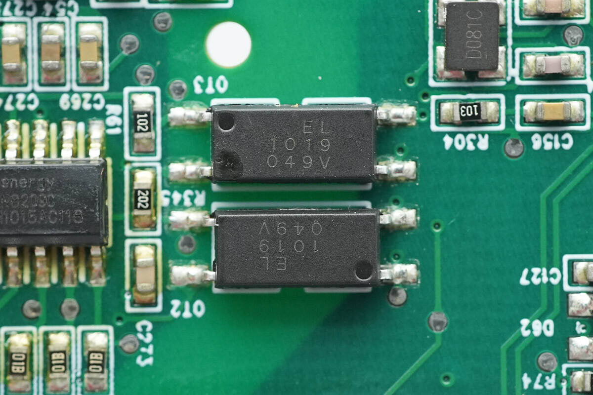
The Everlight EL1019 optocouplers are used for isolated communication.
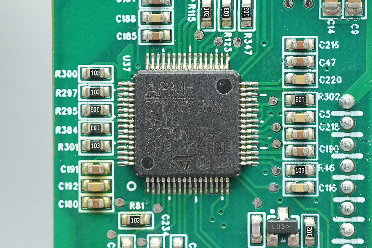
The PFC controller is from STMicro, model STM32F334R8T6. It is a mainstream mixed-signal ARM Cortex-M4 MCU with built-in DSP and FPU, integrating 64KB FLASH and 12K SRAM, and supporting parity checking. The CPU frequency is 72MHz, with built-in 5Msps 12-bit ADC, comparator, operational amplifier, and high-resolution timer, supporting 6-channel PWM signal output, and using LQFP64 package.
Close-up of an external clock crystal.
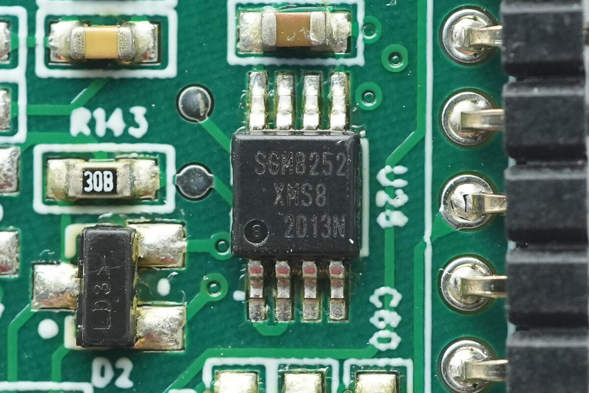
Close-up of the SGMICRO SGM8252 op-amp.
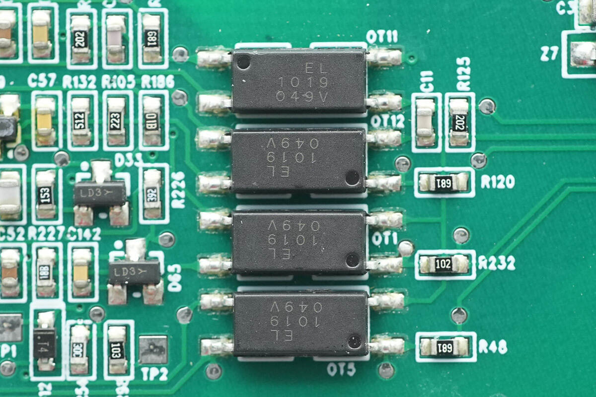
The Everlight EL1019 optocouplers are used for isolated communication.
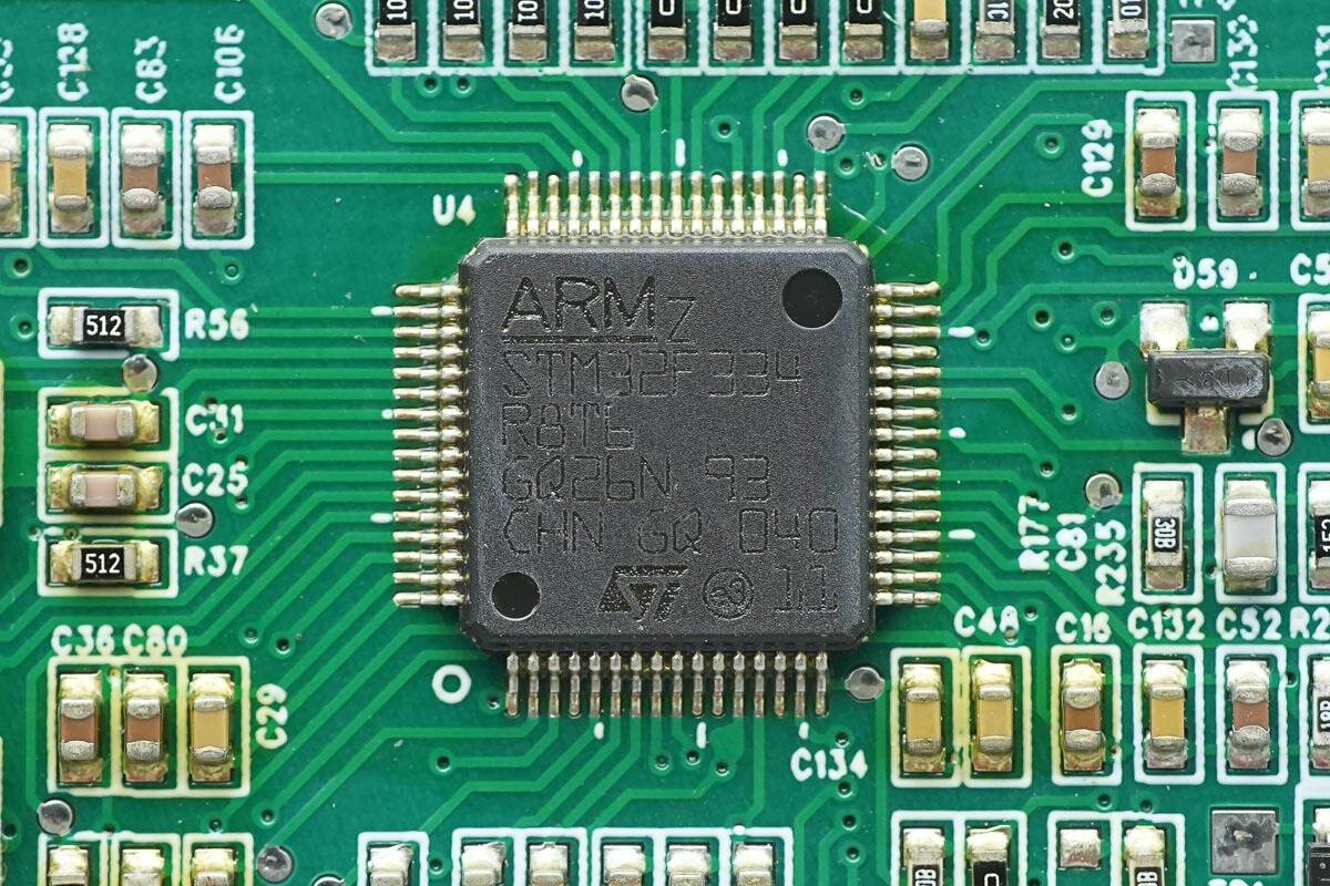
The LLC controller is also from STMicro, model STM32F334R8T6.
Close-up of the chip's external clock crystal oscillator.
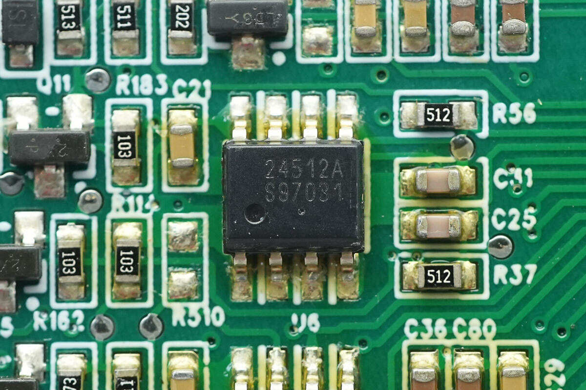
The memory is from Onsemi, marked with 24512A, model CAT24C512, with a capacity of 512Kb, supports a working voltage of 1.8-5.5V, and uses an SOIC-8 package.
The memory is from Microchip, marked with 02DM, model AT24C02D, with a capacity of 2Kb, and uses an SOIC-8 package.
The buck chip is from MPS, marked with ATU, model MP1652. It is a synchronous buck converter with a 4.2-18V input voltage and a 2A output current. The chip integrates a MOSFET, which has fast load transient response, a switching frequency of 680KHz, and supports overcurrent protection and overheat shutdown. It is packaged in SOT563.
The other buck chip is the same model.
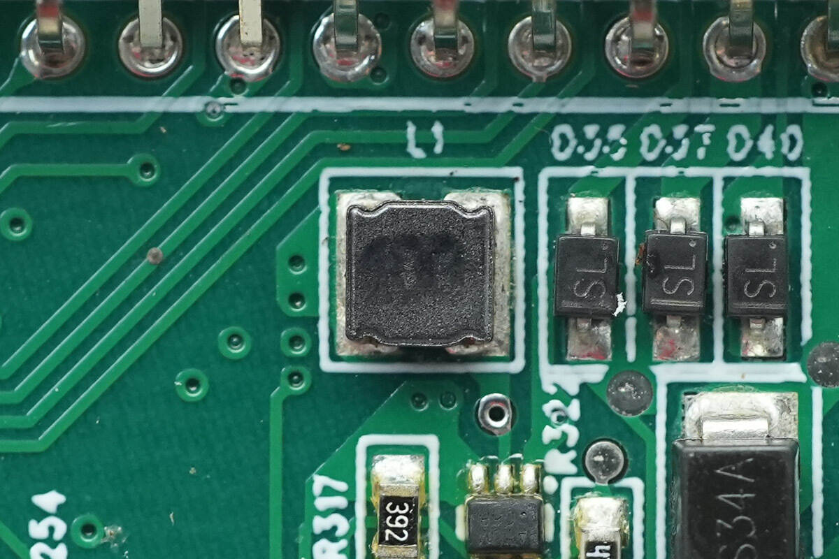
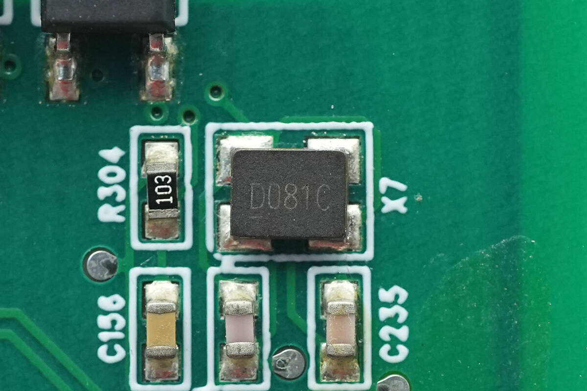
Close-up of the external 10μH buck inductor.
Close-up of the external 10μH buck inductor.
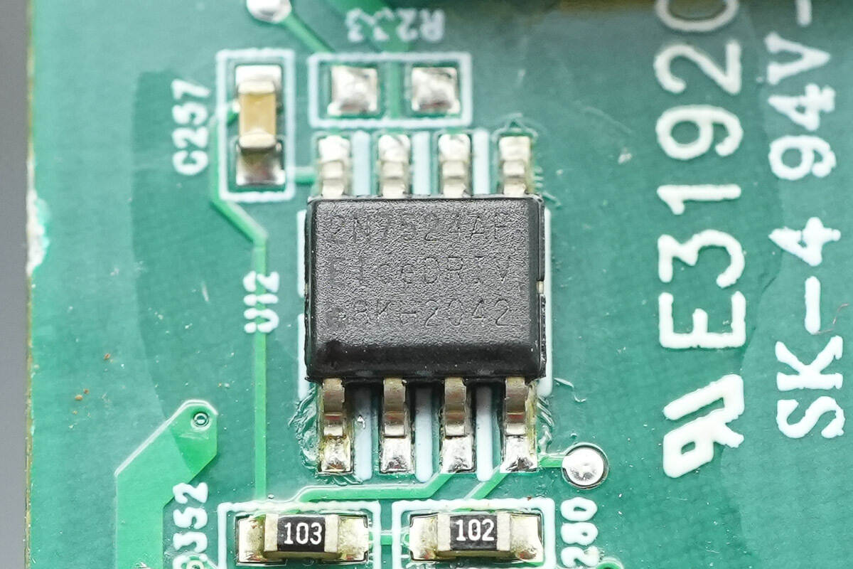
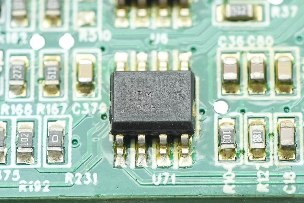
The driver is from Infineon, model 2EDN7524F, and is a dual low-side driver with two independent drivers built in. It supports 5A output current and is suitable for MOS and GaN applications. It is packaged in a DSO-8 package.
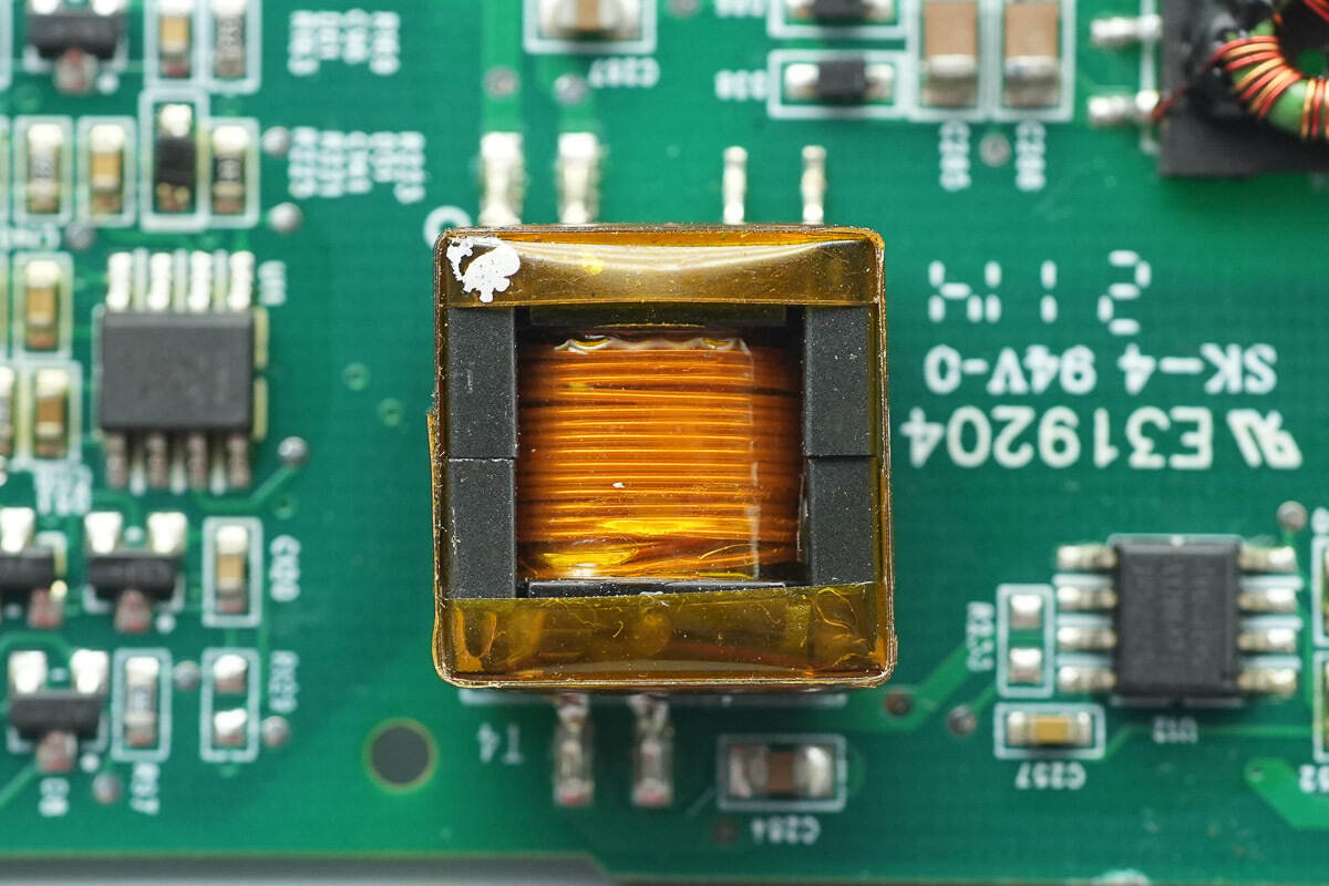
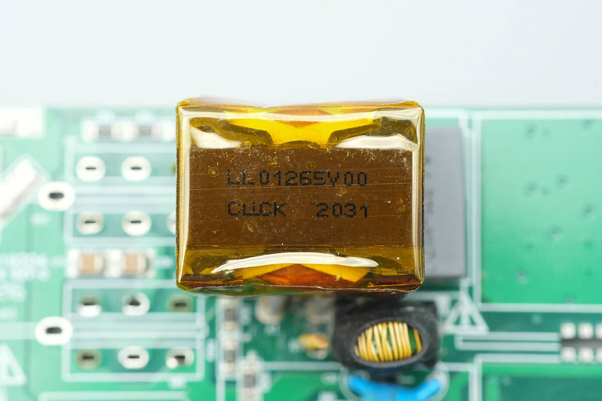
Close-up of the transformer used for isolated power supply.
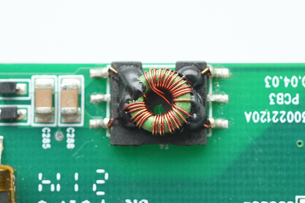
The other transformer uses a magnetic winding system.
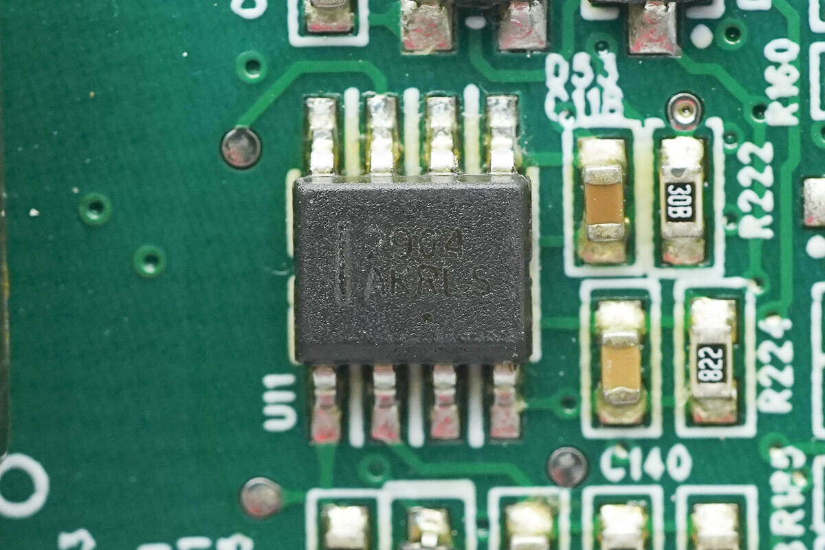
Close-up of the Onsemi LM2904 dual op-amp.
The other op-amp is of the same model.
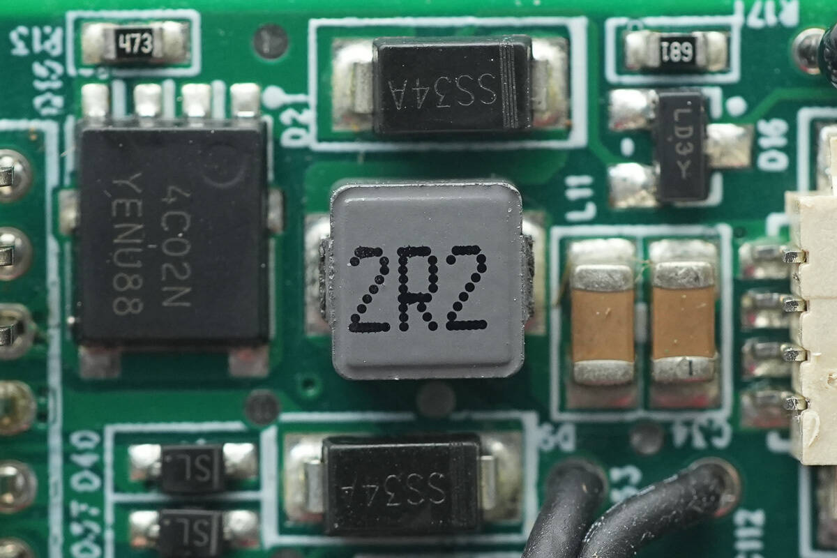
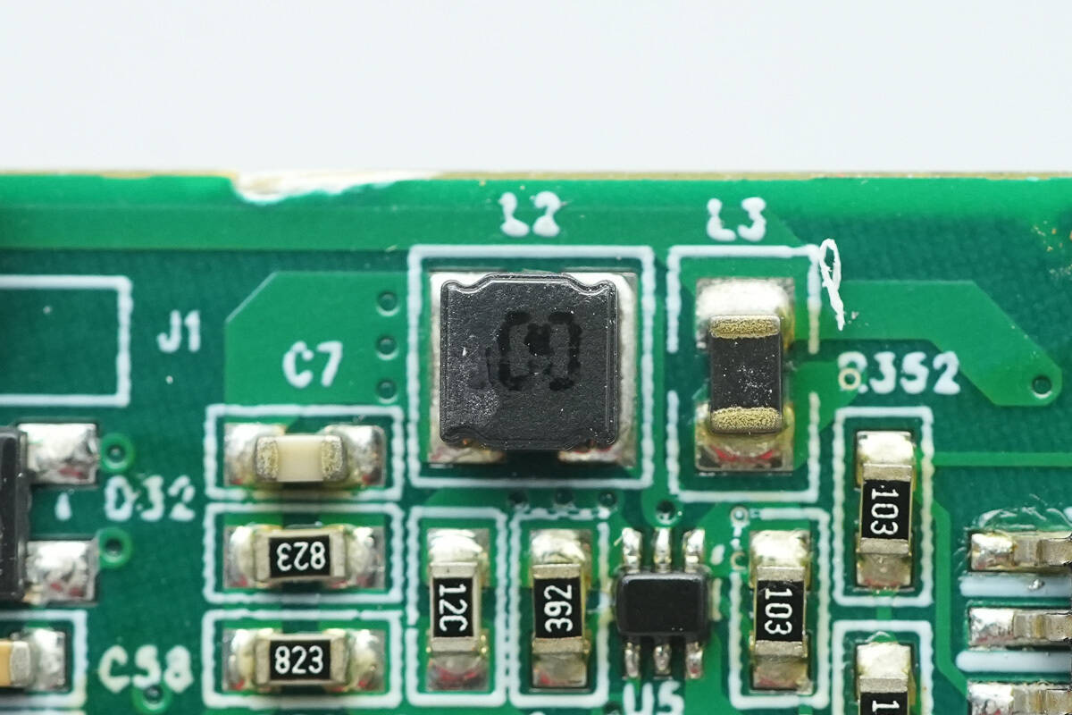
Close-up of a 2.2μH filter inductor.
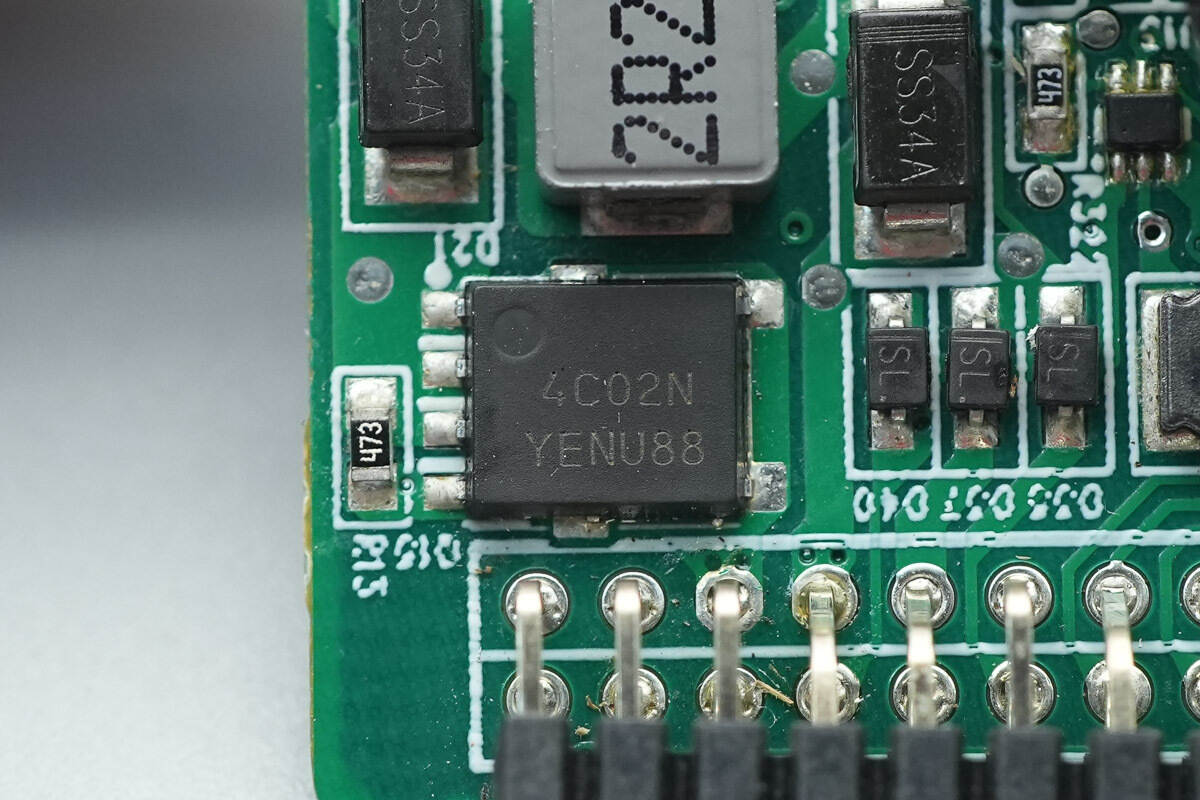
The switching MOSFET is from Onsemi, model NVMFS4C302N.
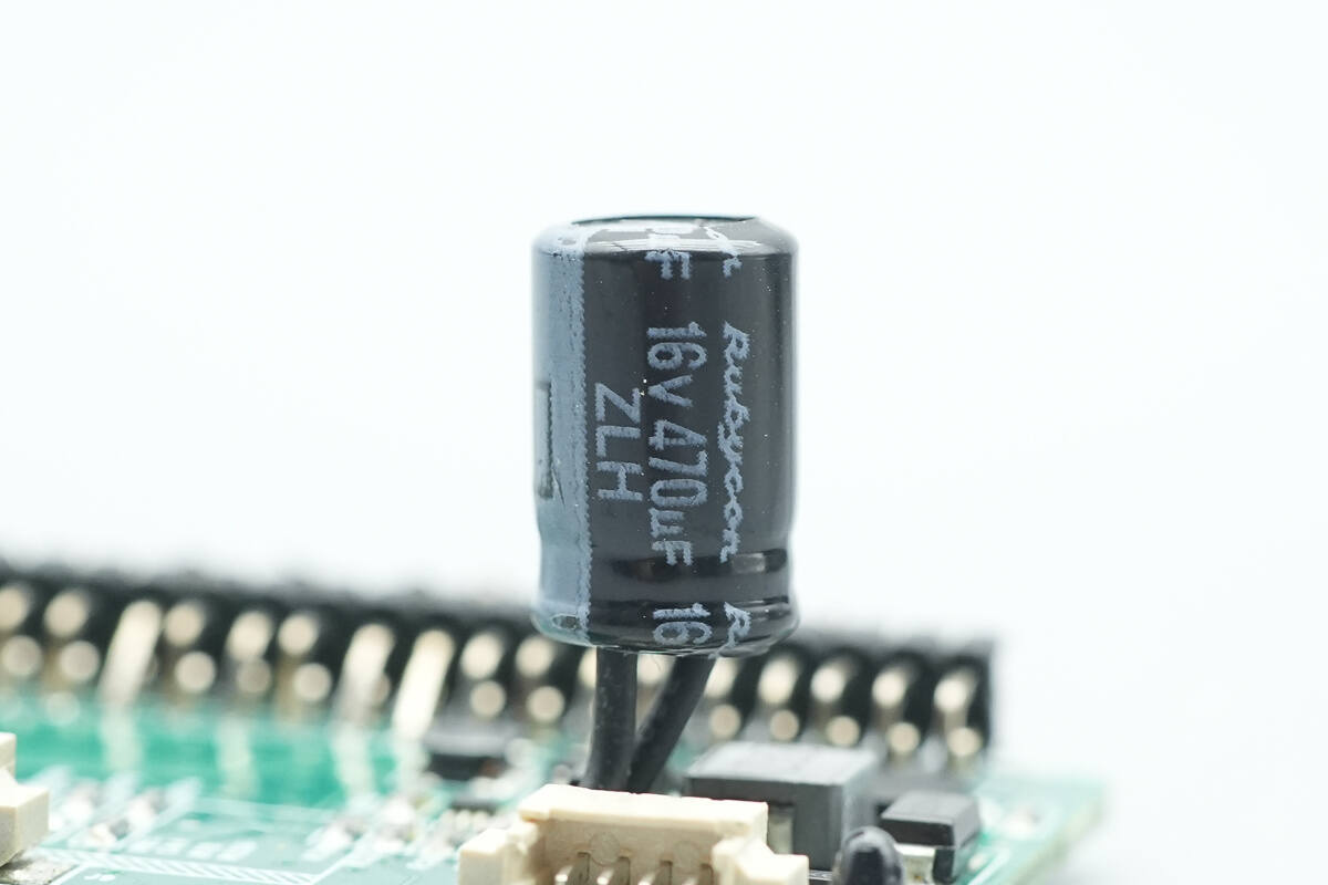
The filter capacitor is rated at 16V 470μF.
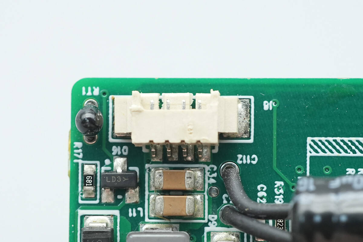
Close-up of the socket for the cooling fan.

Close-up of the thermistor that detects intake air temperature.
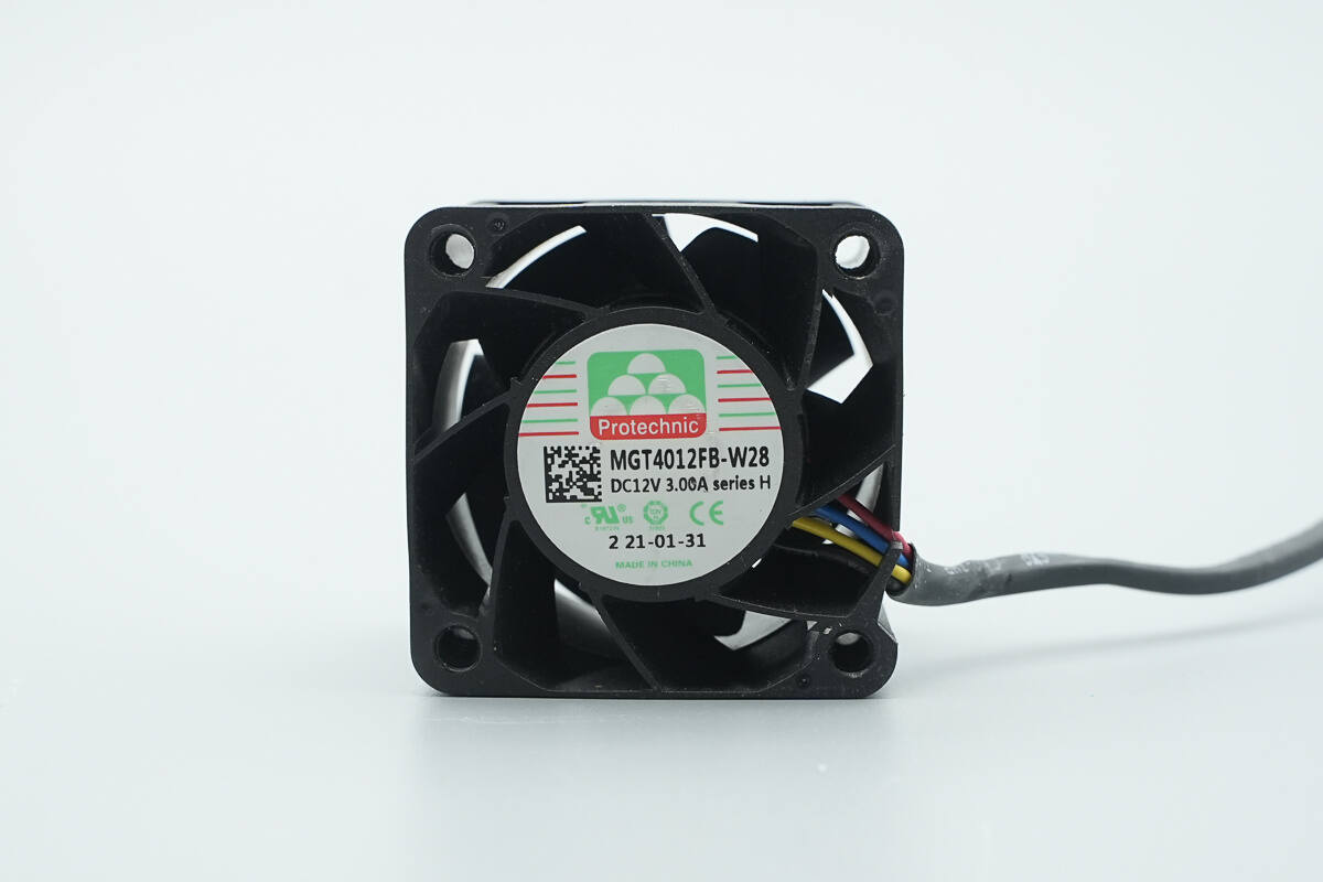
The cooling fan is from PROTECHNIC, model MGT4012FB-W28, with a specification of 12V3A, and is equipped with stationary blades.
Well, those are all components of the Gospower 3000W Switching Power Supply.
Summary of ChargerLAB
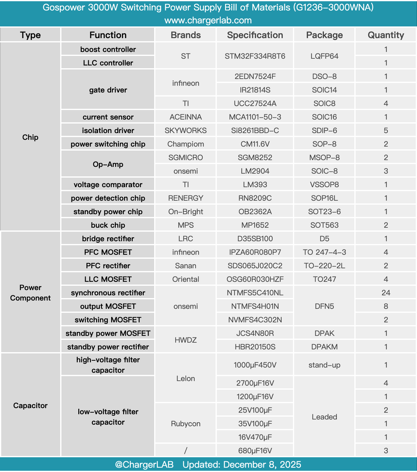
Here is the component list of the Gospower 3000W Switching Power Supply for your convenience.
The power supply, model G1236-3000WNA, is part of the T265 Titanium series, supporting 100-240V AC and 240V HVDC input. The input side features a C20 power inlet. The rated output voltage is 12.2V, with an output current of 245A, while the standby power output is 12V with 3A. The module is equipped with a built-in cooling fan, drawing air in from the output side and expelling it from the input side for efficient heat dissipation.
After taking it apart, we found that it uses two STMicro STM32F334R8T6 MCUs, each controlling the PFC boost and LLC operation. The PFC MOSFETs are Infineon IPZA60R080P7 MOSFETs, and rectification is handled by Sanan SDS065J020C2 silicon carbide diodes. The LLC MOSFETs are Oriental OSG60R030HZF.
The synchronous rectifiers are Onsemi NTMFS5C410NL, driven by the TI UCC27524A. The standby power chip is On-Bright OB2362A, with MOSFETs and rectifiers from HWDZ. Both the high-voltage filter capacitors and output filter capacitors are from Lelon. The PCBA modules are assembled using small PCBs, maximizing space efficiency. The construction is solid, and the components are of reliable quality.
Related Articles:
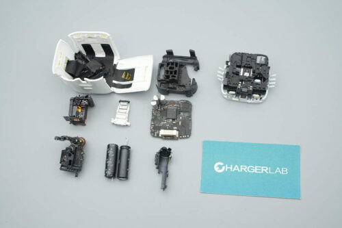
1. Teardown of CUKTECH 25 Power Bank SE (LPB252N)
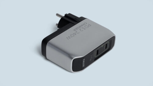
2. Teardown of ASUS Adol 140W GaN Quick Charger (AC140-020A)
3. Teardown of MIIIW 140W GaN Charger CA514 Pro (iCA1404)