Introduction
We got a DC-DC converter from Foton Aumark. The converter features an aluminum alloy housing for effective heat dissipation. The model number is SDM302BYUM-LGC1, which supports a DC input range of 200–750V and provides a DC output of 27.5V at 110A, with a rated power of 3kW.
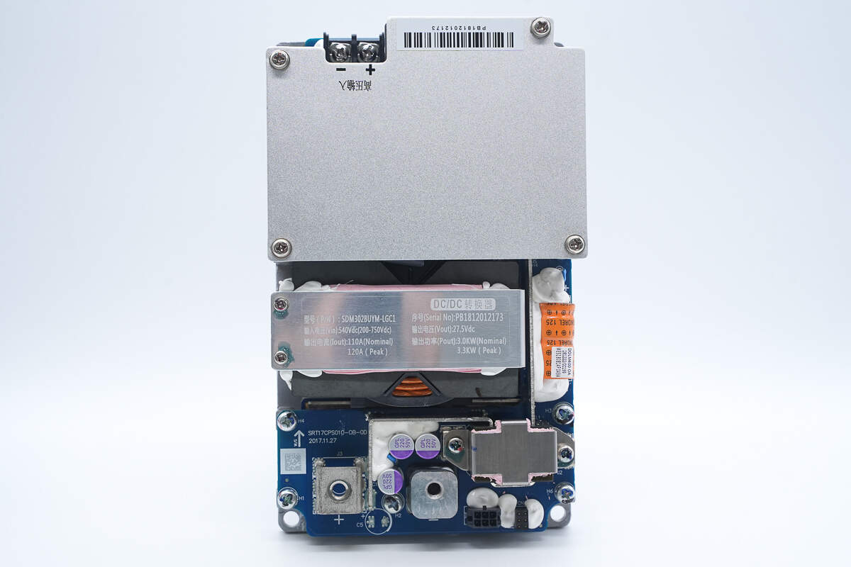
The converter uses an aluminum base as the negative output terminal. The PCBA module is secured with screws and thermally coupled to the housing via thermal pads to improve heat transfer. High-voltage input is connected via terminals, the positive output is also terminal-connected, and the negative output is integrated with the housing. Next, we’ll take a look inside to examine its internal structure and components.
Product Appearance
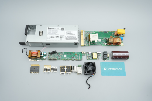
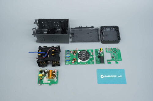
All individual modules are mounted and fixed in place with screws.
The top section features an aluminum alloy cover, while the bottom houses the transformer and output end. Mounting screw holes are located at all four corners.
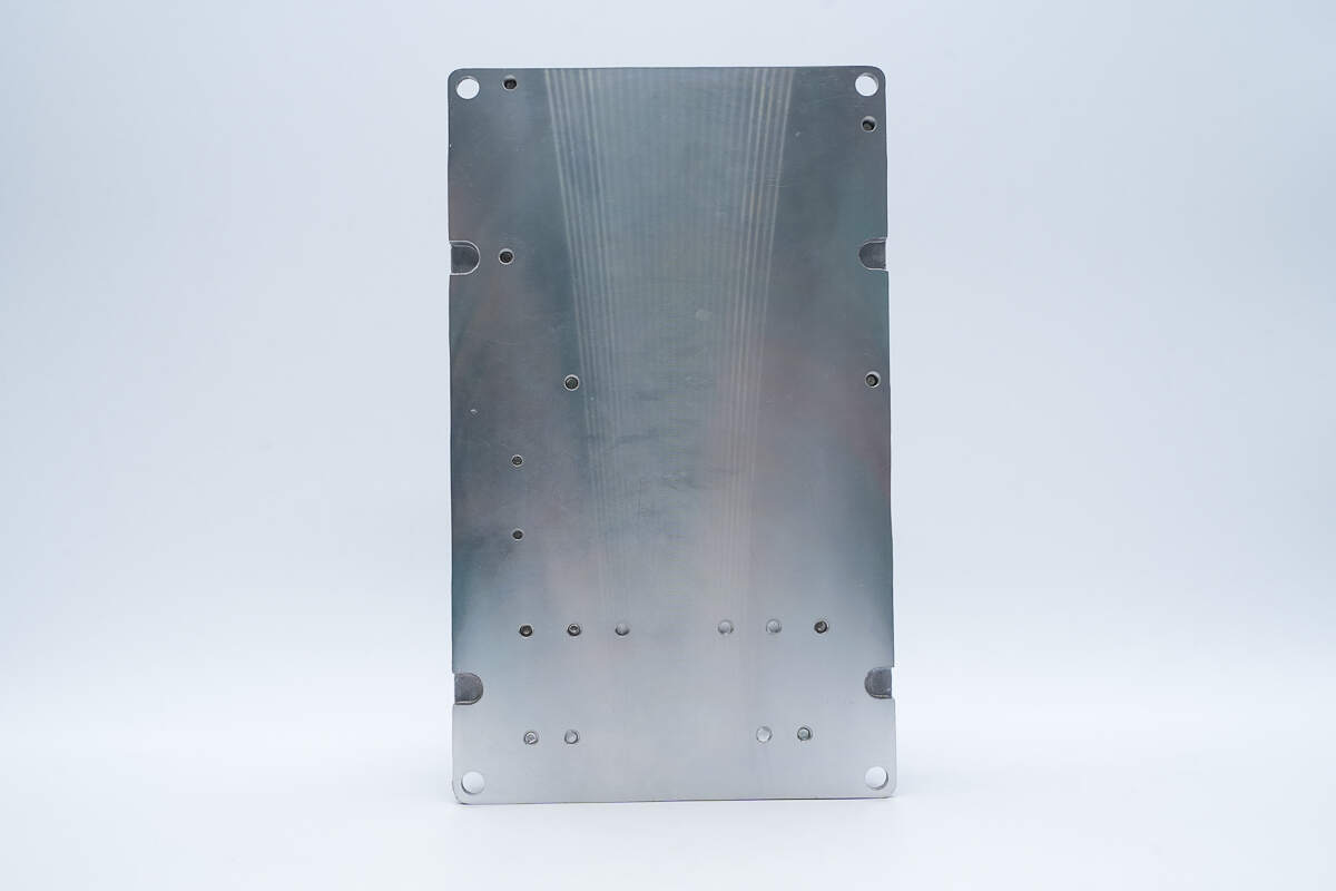
Mounting screw holes are also present on the back side.
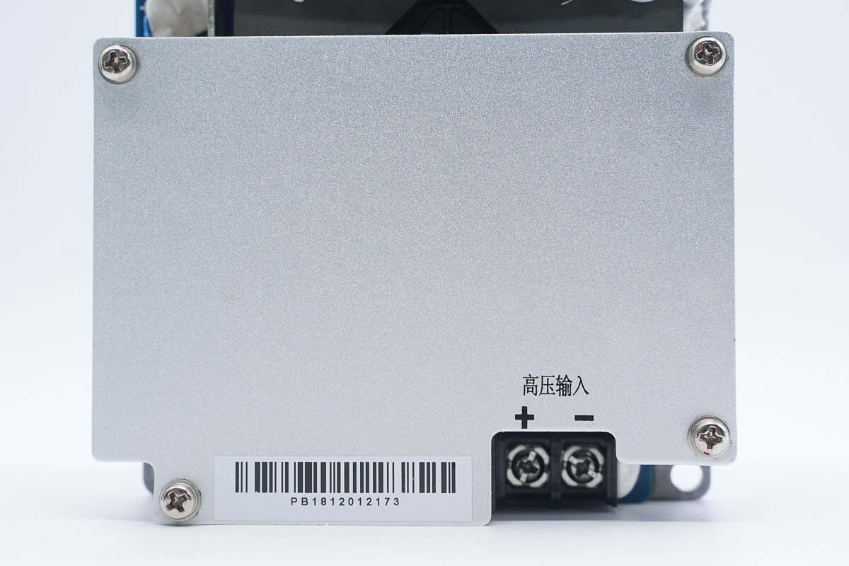
The cover is secured with screws, and high-voltage input terminals are located at the bottom.
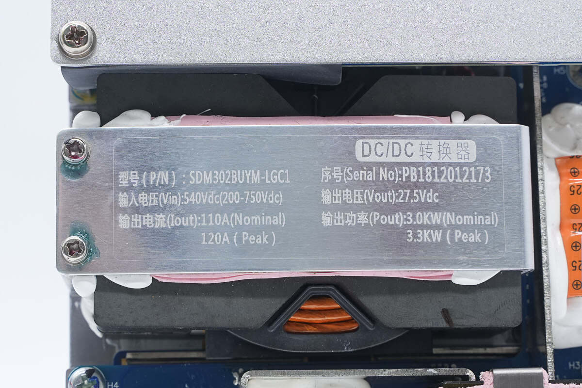
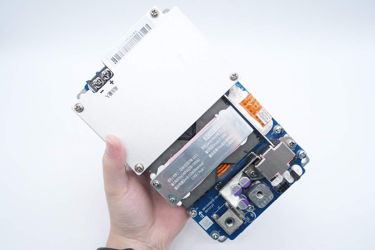
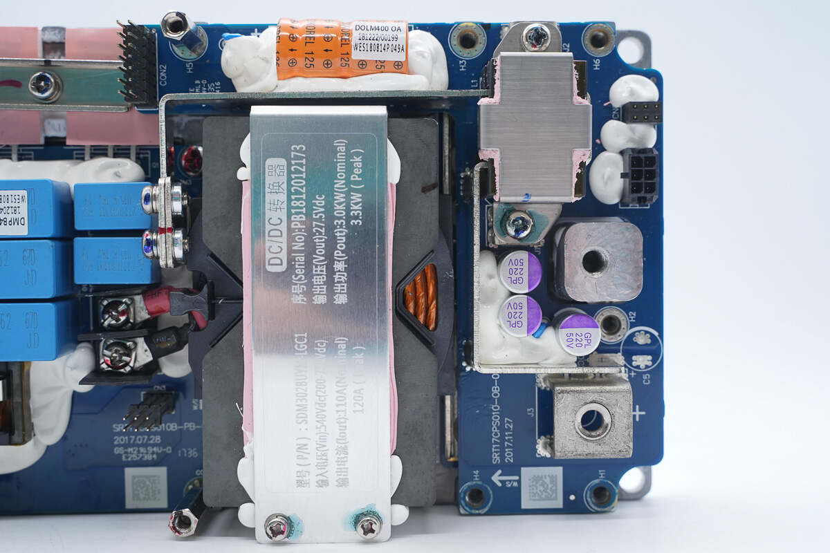
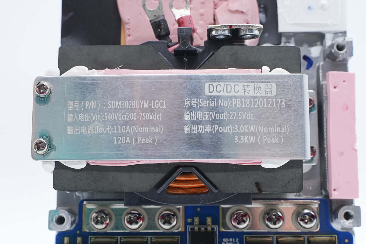
The transformer cover is labeled with specification information:
Model: SDM302BUYM-LGC1
Input Voltage: 540 VDC (200–750 VDC)
Output Voltage: 27.5 VDC
Output Current: 110 A (rated), 120 A (peak)
Output Power: 3 kW (rated), 3.3 kW (peak)
The lower output PCB features a positive terminal post.
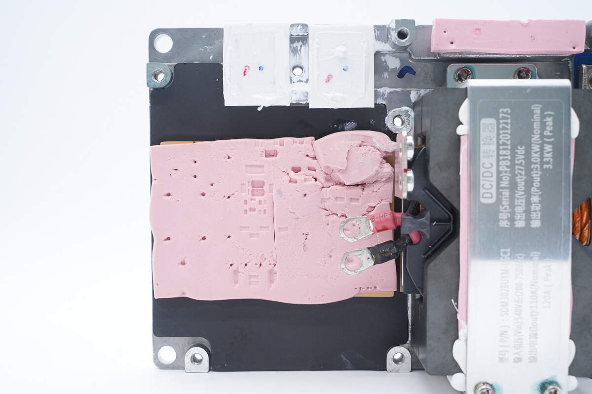
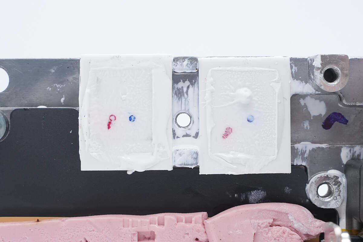
The converter is assembled using studs, with a thermal pad placed between the PCBA module and the aluminum alloy base.
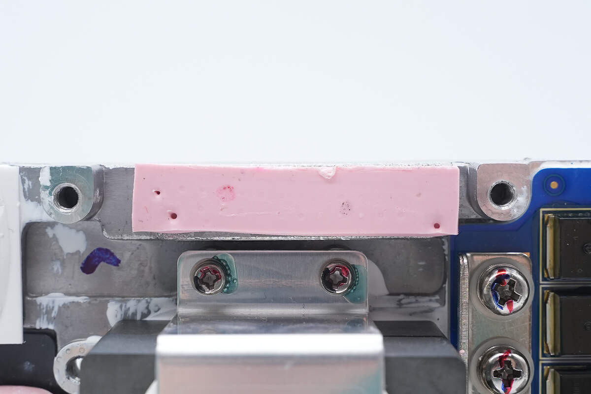
On the right side, a screw-mounted clamp is used for heat dissipation.
The transformer core is secured to the housing with adhesive.
There is an aluminum substrate layer at the bottom of the output PCB.
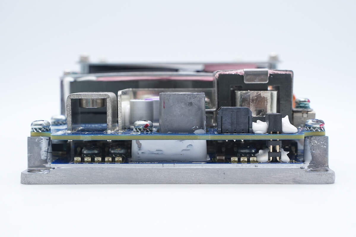
The PCBs are connected via pin headers and connectors.
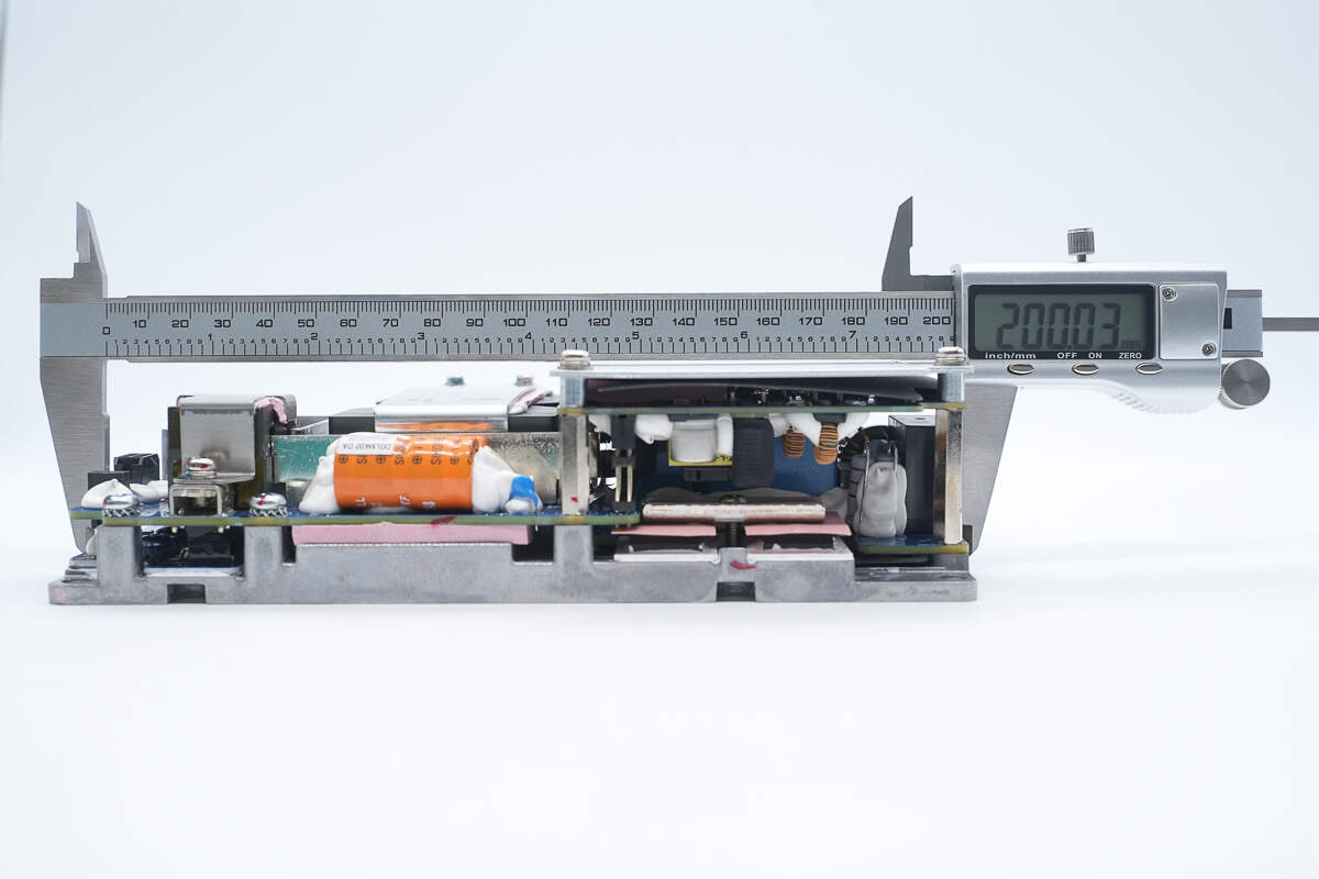
The length is about 200 mm (7.87 inches).
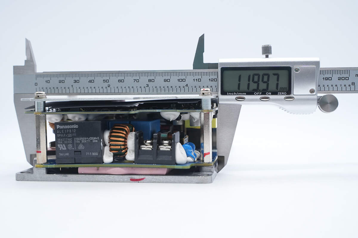
The width is about 120 mm (4.72 inches).
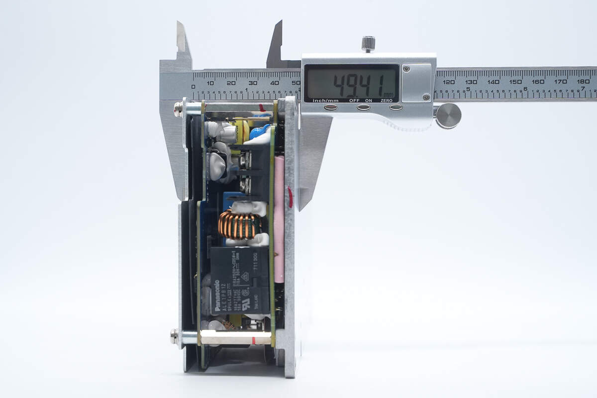
The thickness is about 49.4 mm (1.94 inches).
That's how big it is in the hand.
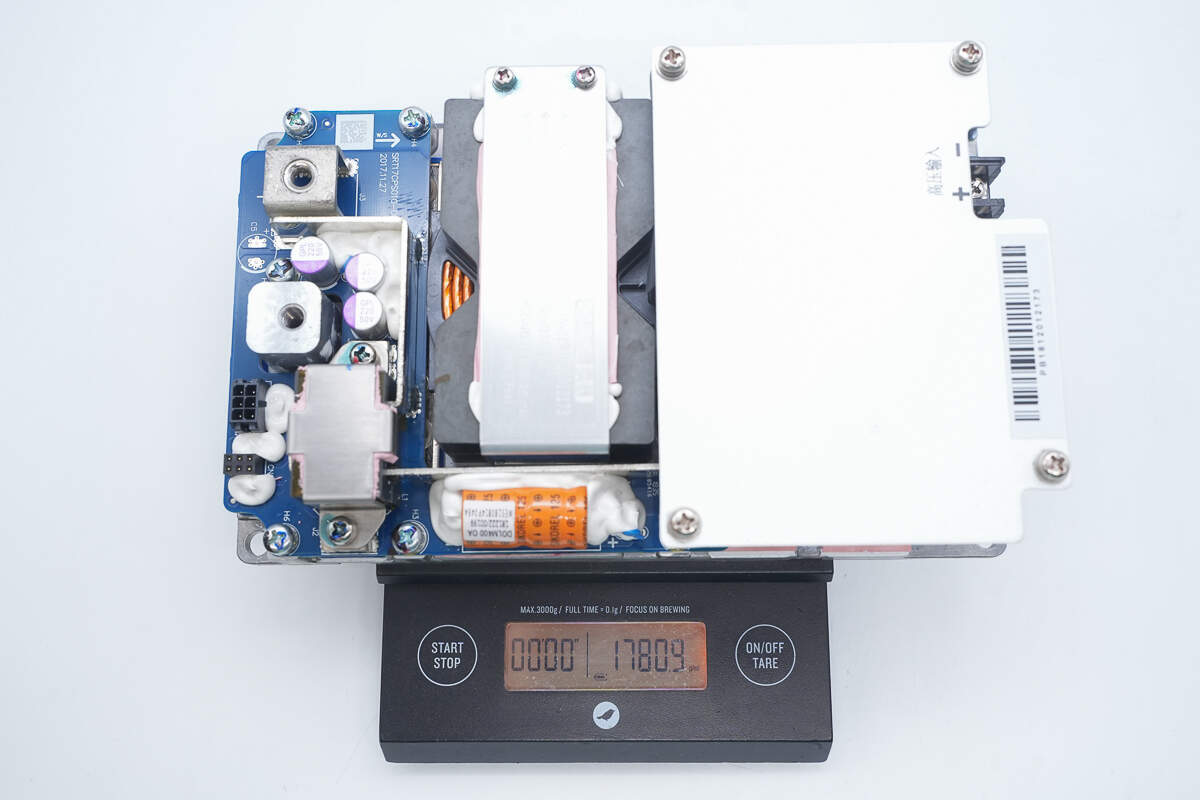
The weight is about 1781 g (62.82 oz).
Teardown
Next, let's take it apart to see its internal components and structure.
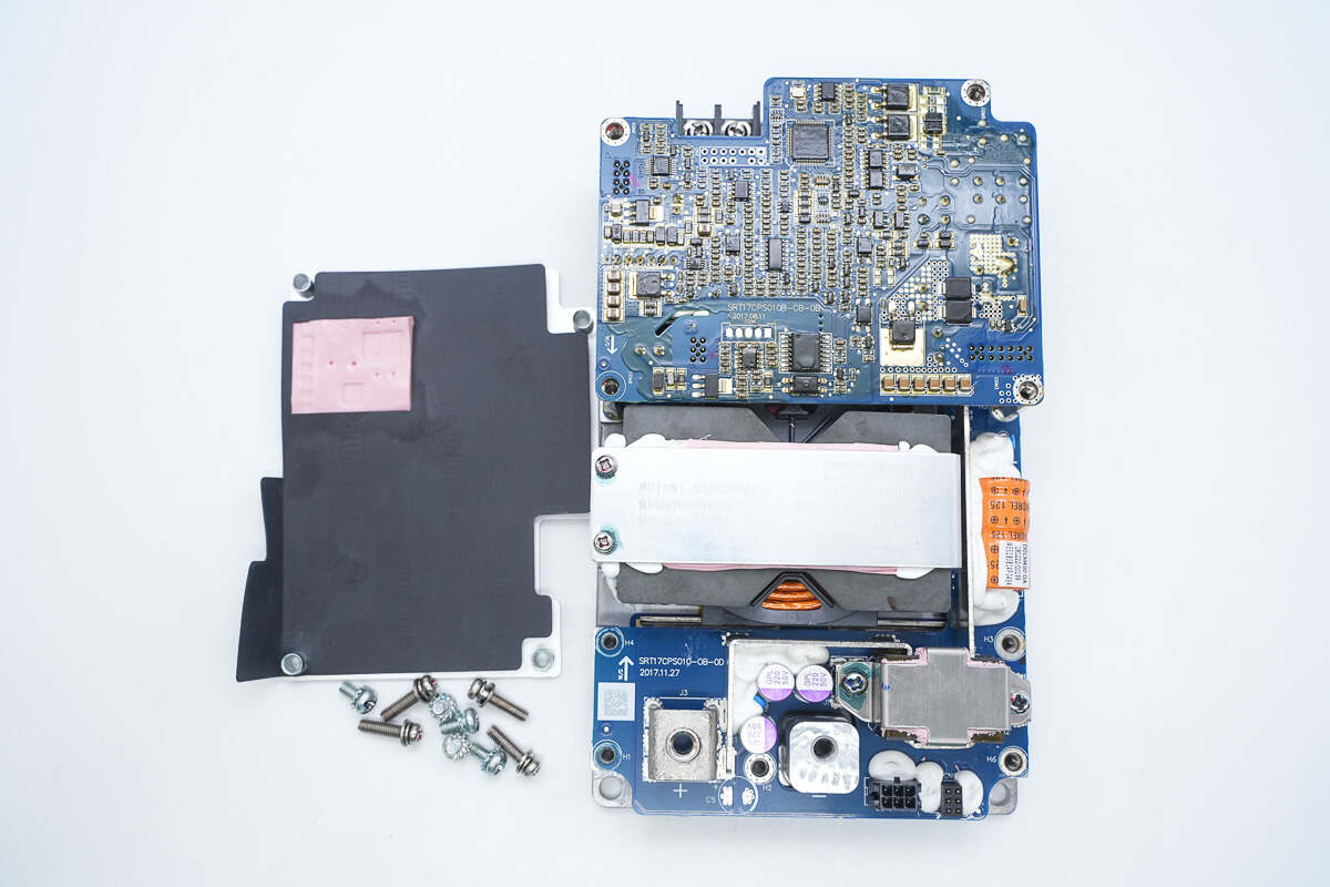
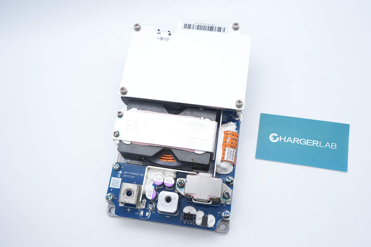
First, remove the screws and take off the aluminum alloy cover. The inner side of the cover includes a Mylar sheet for insulation and a thermal pad for heat dissipation.
Overview of the PCBA module beneath the cover.
Remove the upper PCB, which is connected to the bottom PCB via pin headers.
The lower PCB is secured using studs.
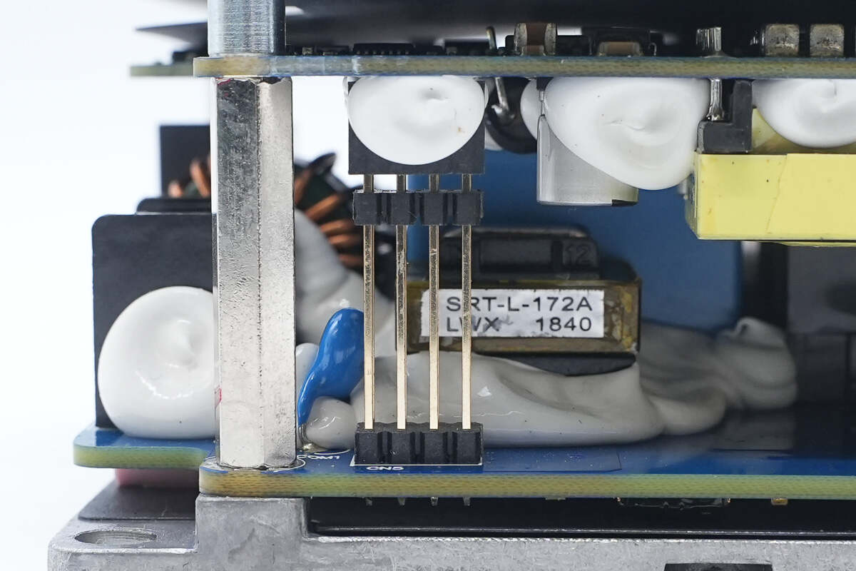
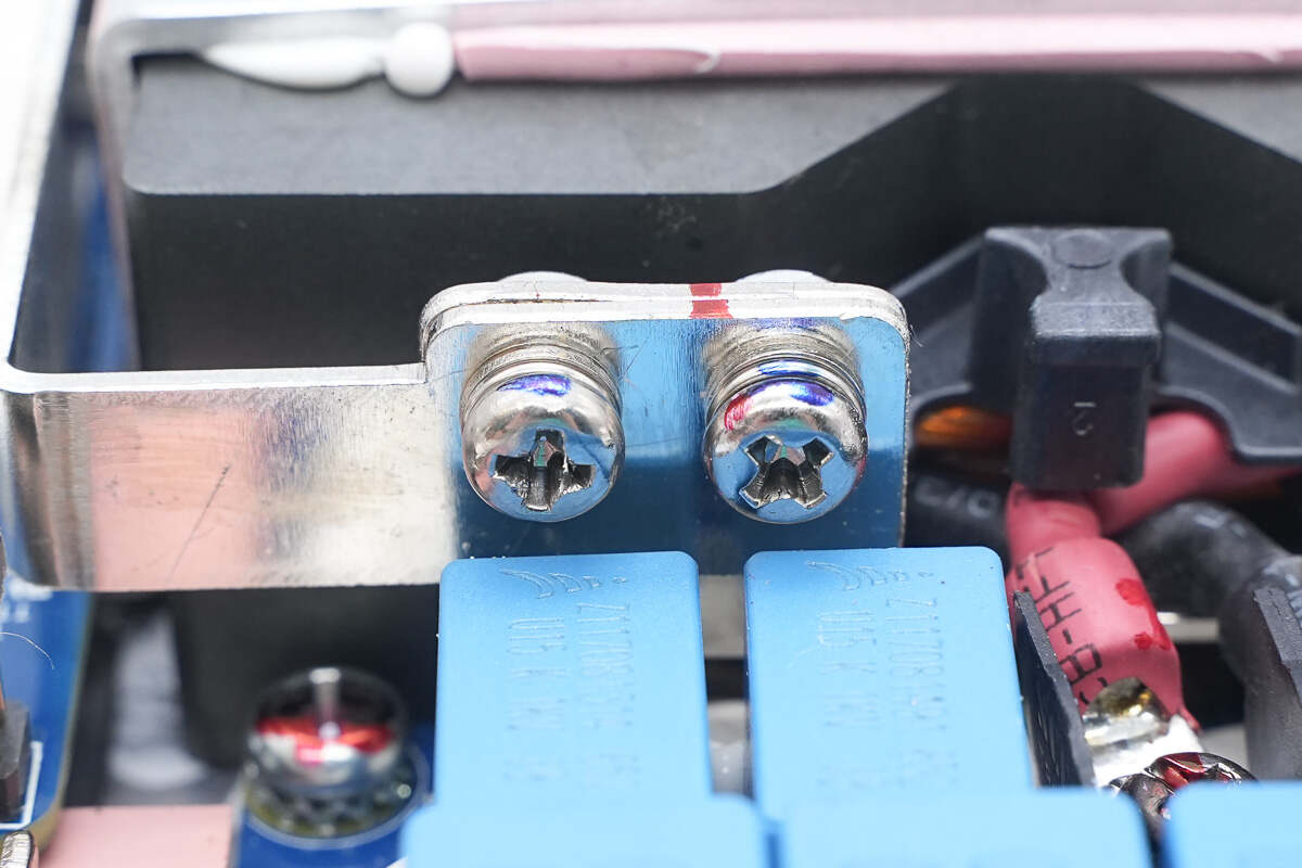
The transformer primary is connected via terminal posts.

The MOSFETs are secured with a pressure plate.
The transformer secondary is connected via copper busbars.
Remove the mounting screws of the output PCB.
Remove the output PCB; an additional aluminum substrate layer is located underneath.
Rectifiers are mounted on the bottom aluminum substrate.

Remove the lower PCB on the input side.
A thermal pad is placed, along with a Mylar sheet for insulation.
Ceramic thermal pads are placed at the MOSFET locations, with thermal grease applied.
There is a thermal pad between the PCB and the aluminum alloy base. The transformer clamp is secured with screws.
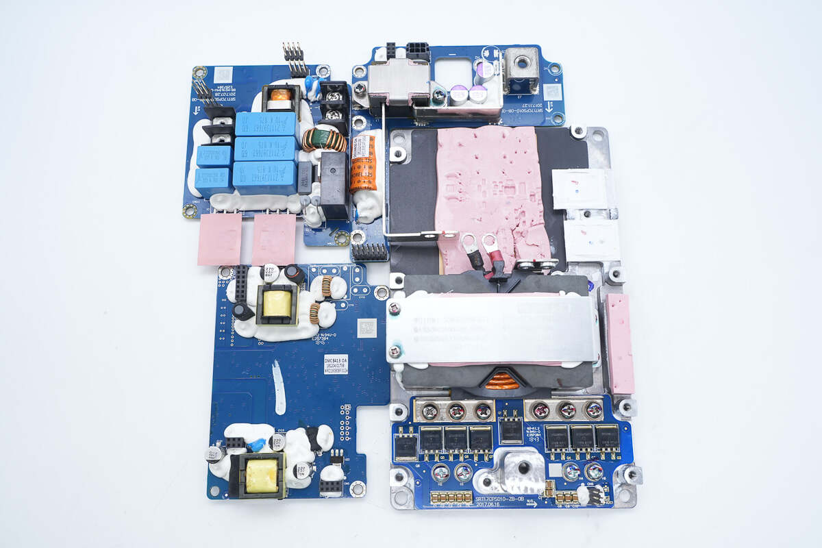
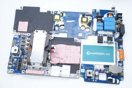
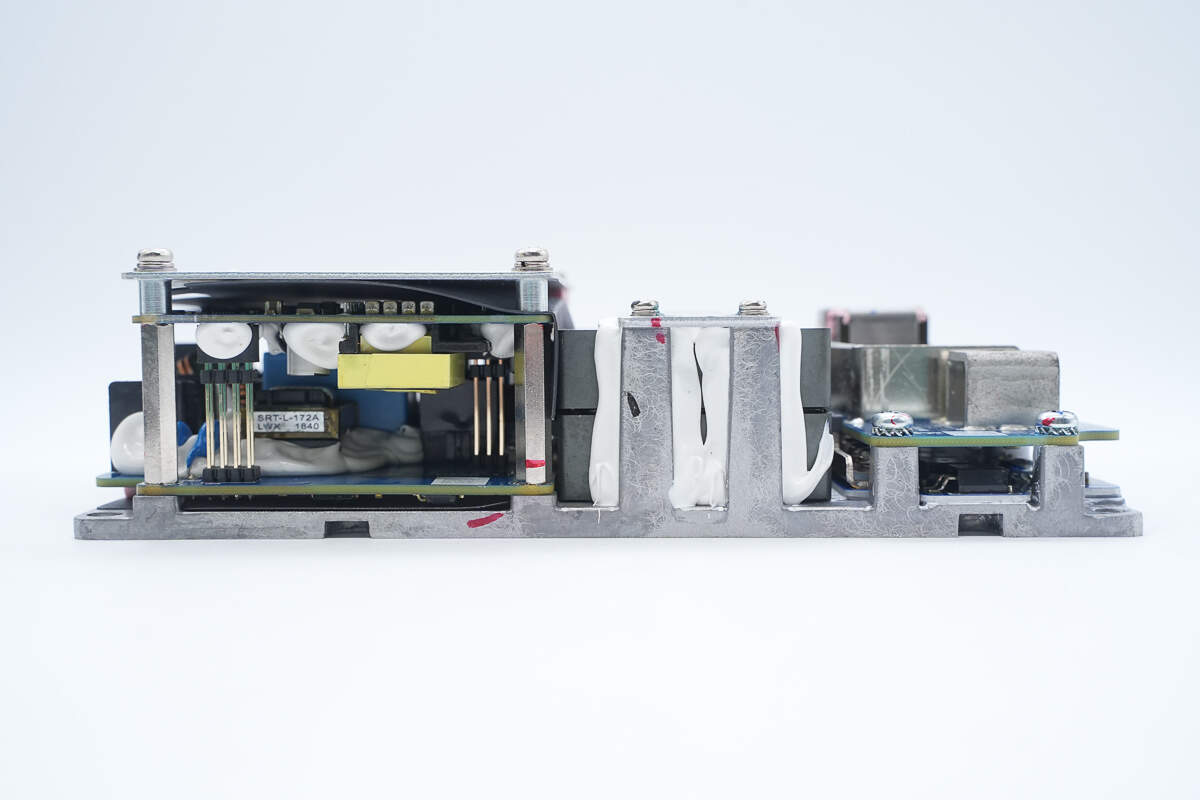
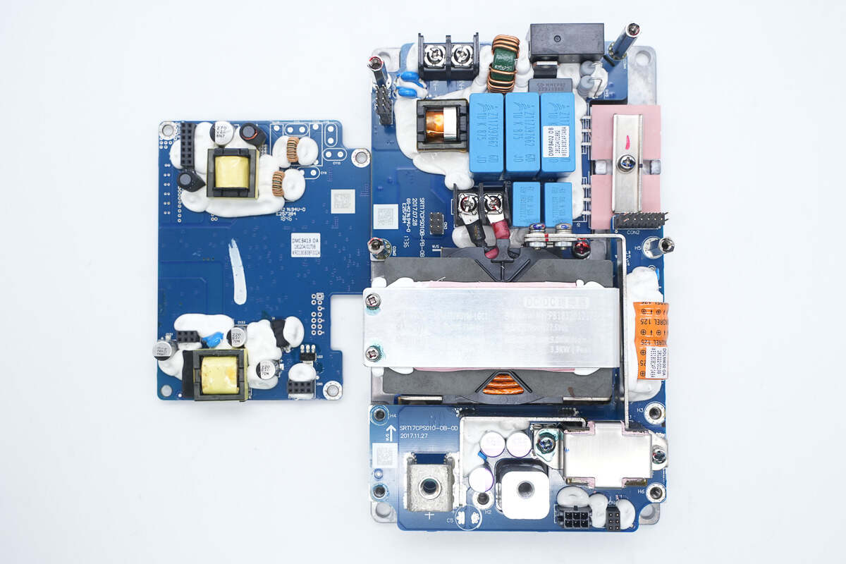
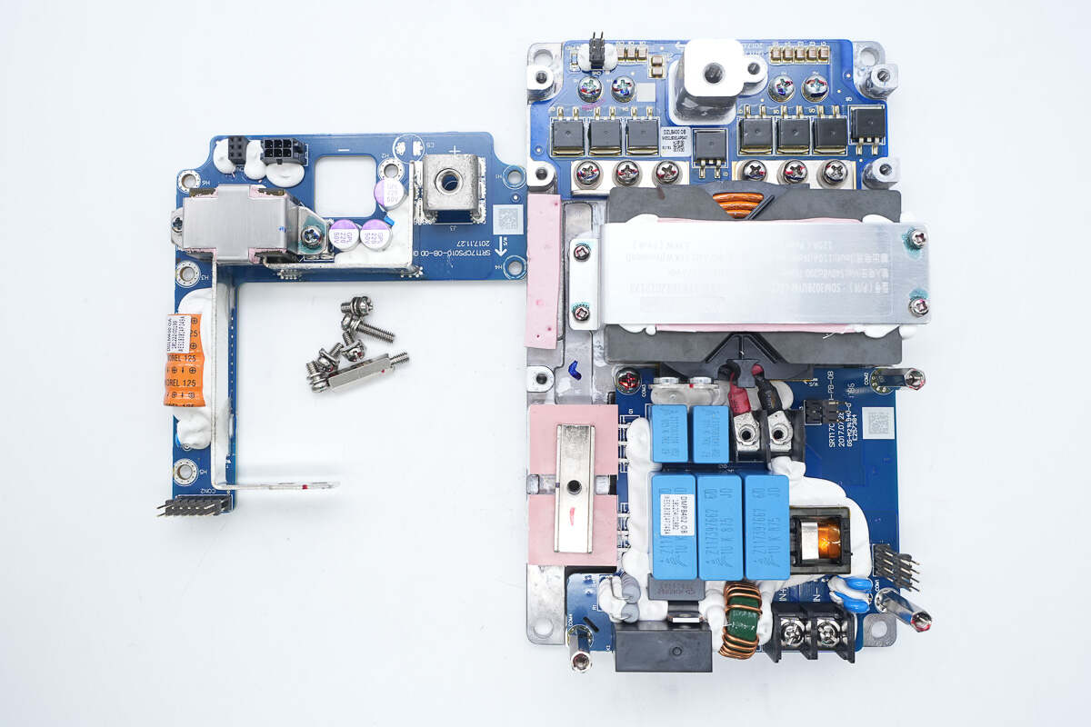
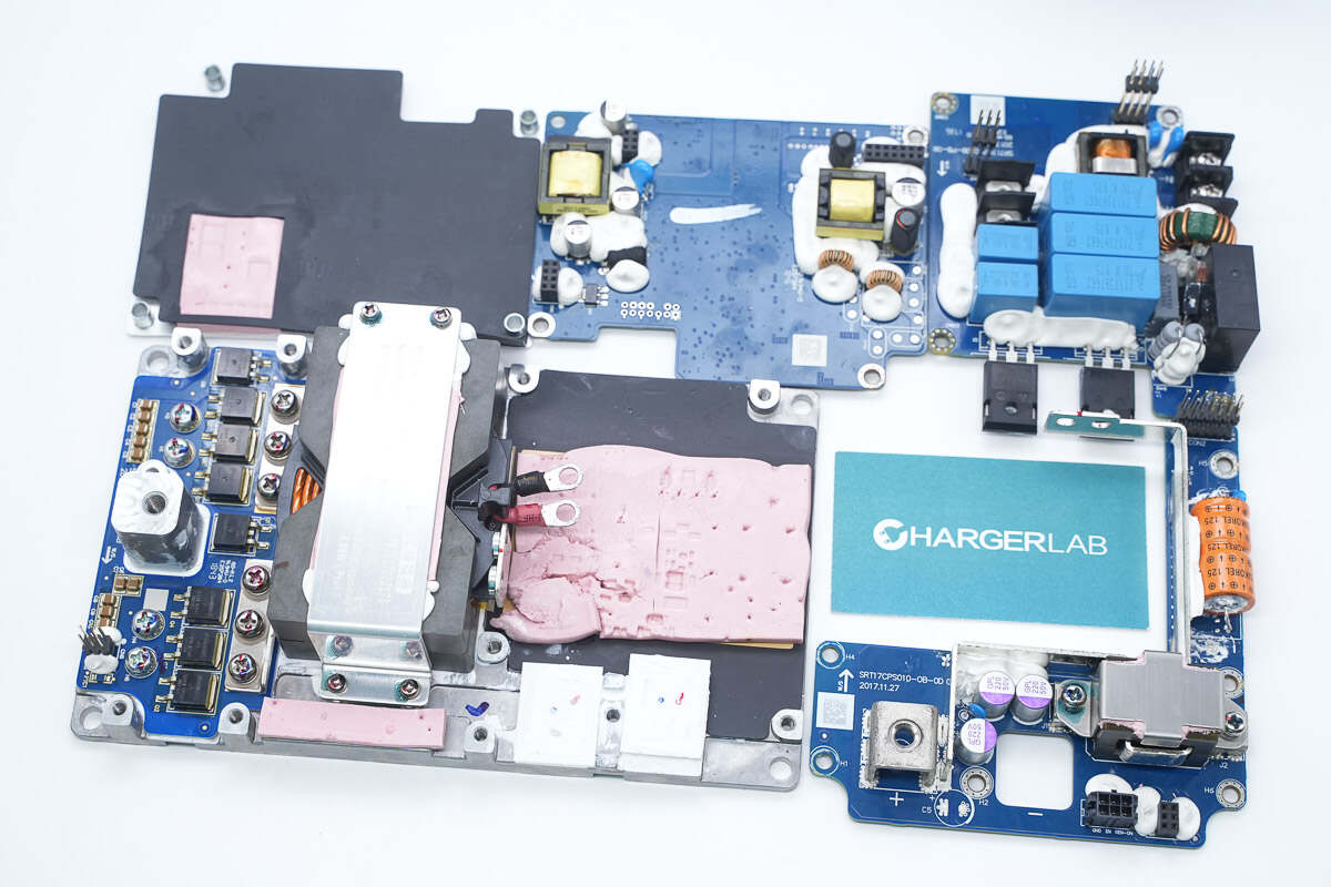
The converter consists of four PCBs in total, with the transformer mounted inside the aluminum alloy base.
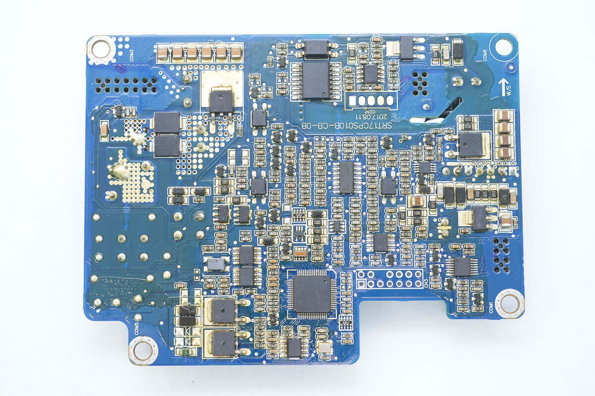
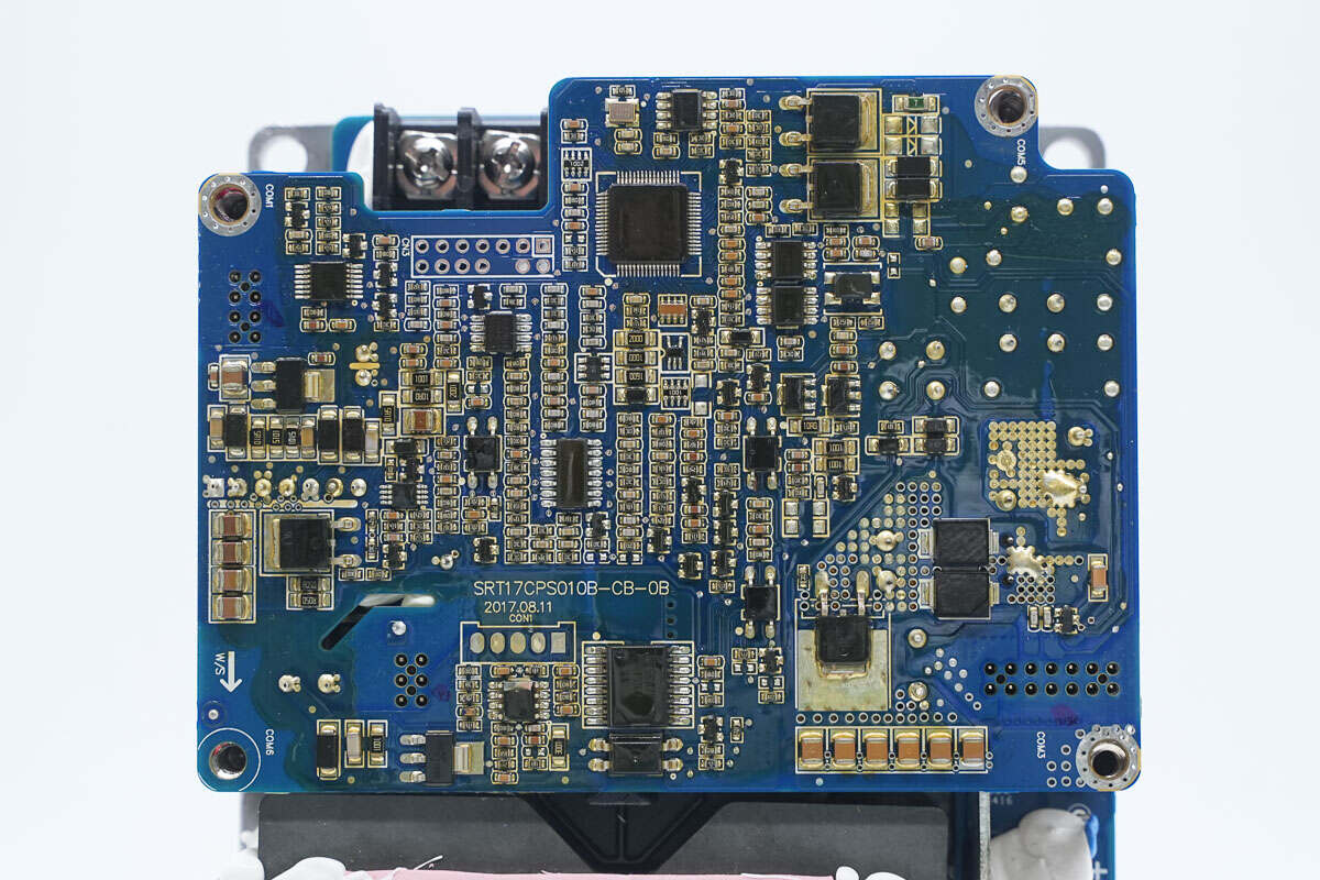
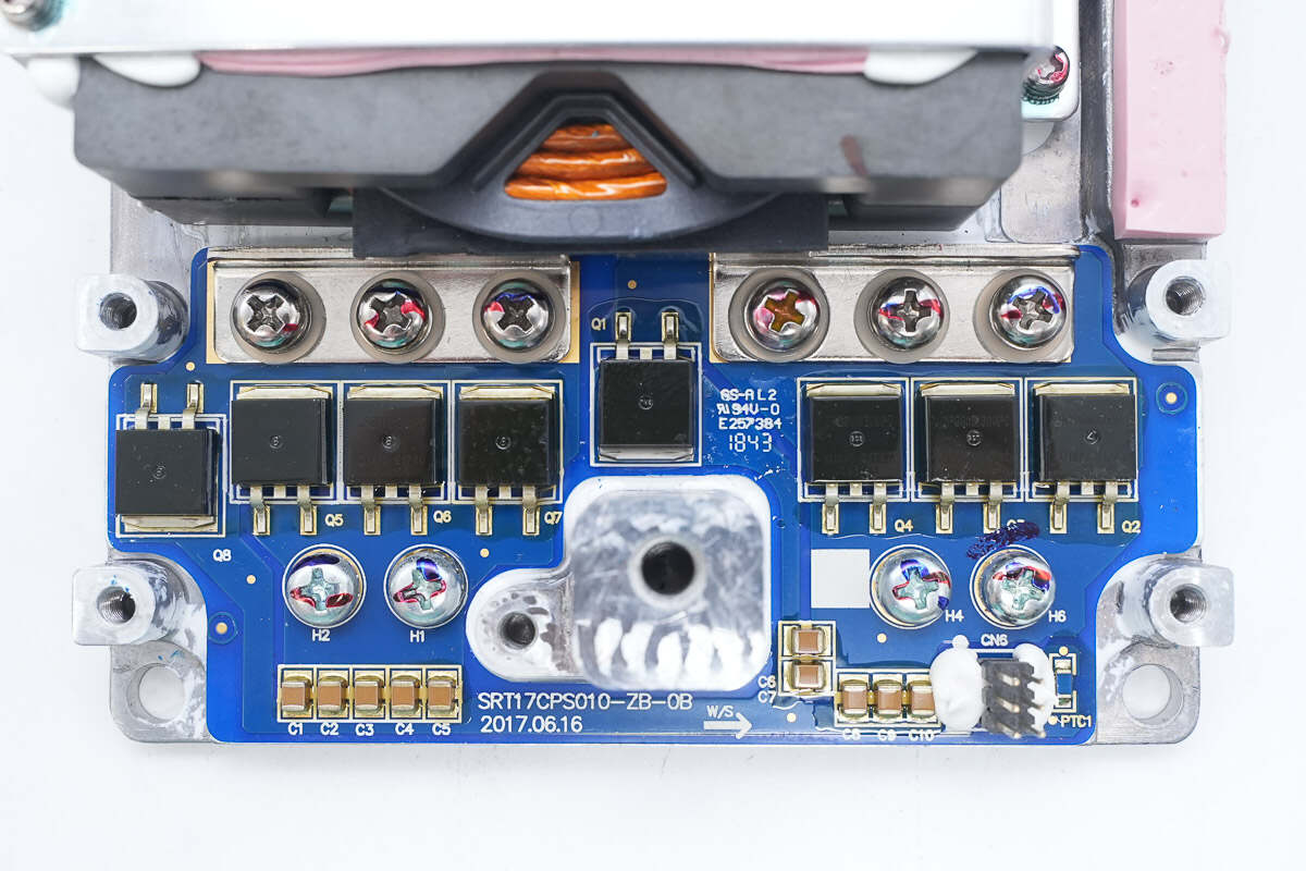
The back side of the control PCB is equipped with an LLC controller, digital isolation chip, MOSFETs, diodes, and other components.
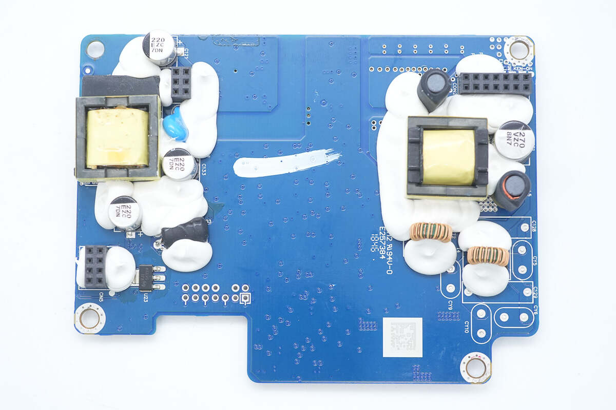
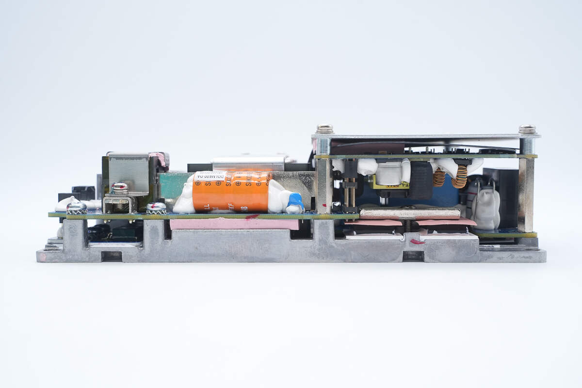
The other side features an isolation transformer, buck inductors, filter capacitors, filter inductors, and other components, all reinforced with adhesive.
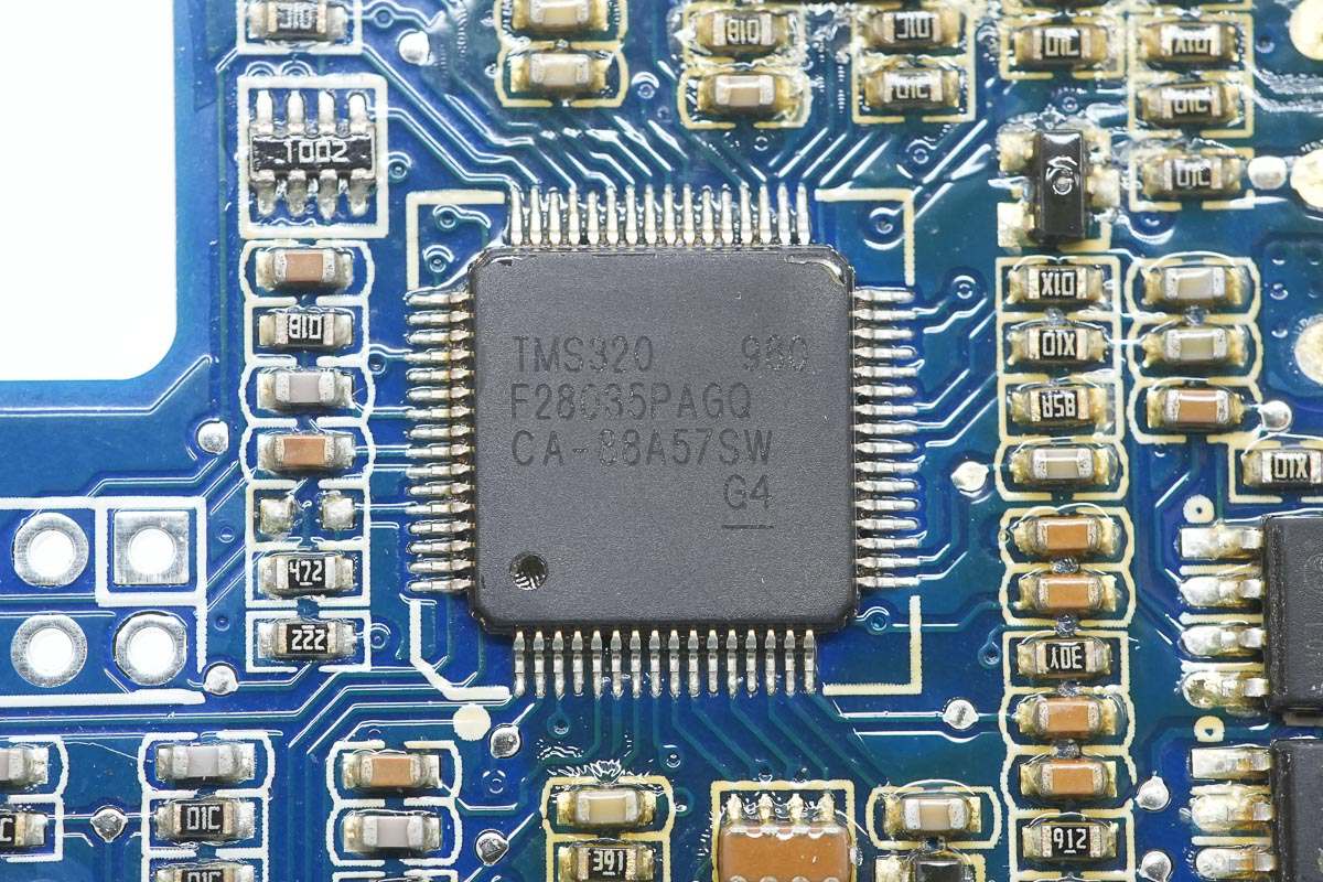
TI’s LLC controller, model TMS320F28035PAGQ, is an automotive-grade MCU from the C2000 series. It features a built-in 32-bit CPU core running at 60 MHz, supports coordinated operations, and offers fast interrupt response and processing. The MCU includes 128 KB of flash memory. It is suitable for applications such as air conditioner outdoor units, DC-DC converters, inverters and motor control, OBC, charging stations, and BLDC motor drives. The device comes in a TQFP64 package.
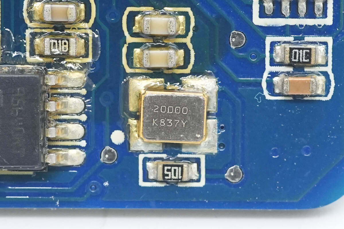
Close-up of the 20.000 MHz clock crystal oscillator.
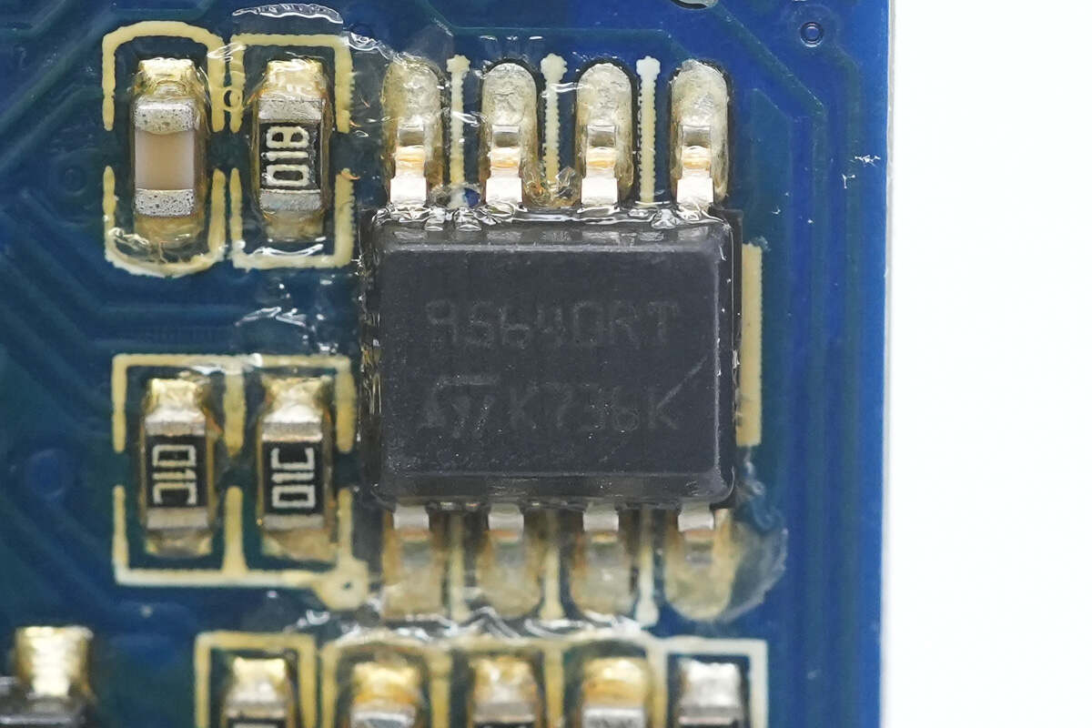
The memory is from STMicroelectronics, model M95640, with a capacity of 8KB, packaged in SO8.
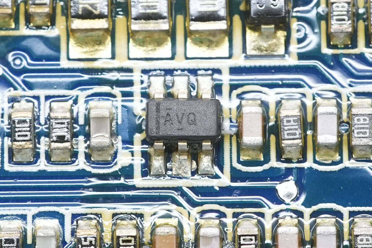
The voltage monitoring chip is from TI, marked with AVQ, model TPS3808G25. It features ultra-low quiescent current and high threshold accuracy, supports manual reset input, and comes in a SOT-23 package.
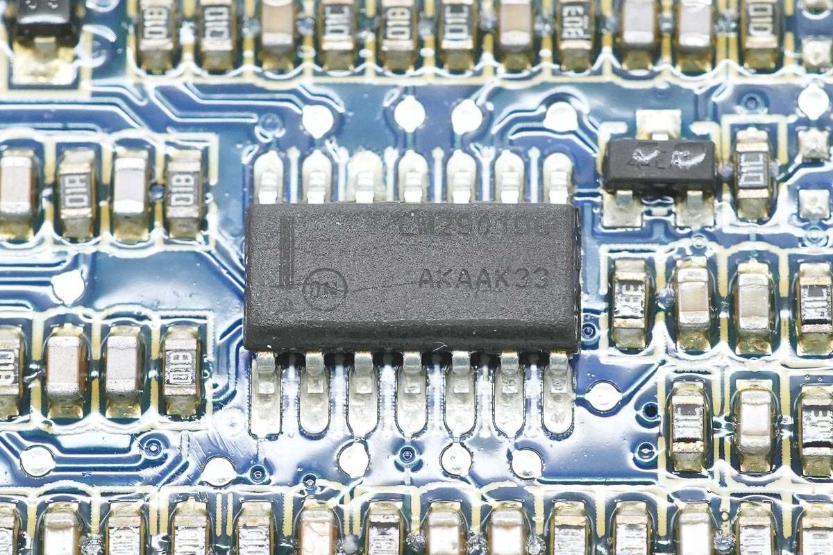
The voltage comparator is from Onsemi, model LM2901. It is a single-supply, four-channel comparator supporting up to 36V supply voltage and comes in an SOIC-14 package.
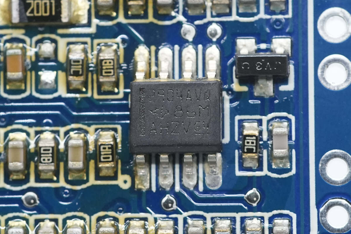
The dual operational amplifier is from TI, model LM2904-Q1. It is an automotive-grade dual op-amp packaged in SOIC-8.
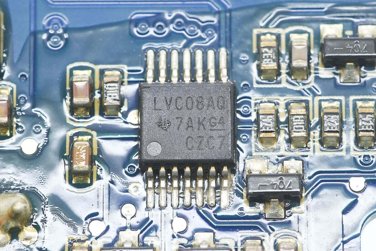
The AND gate chip is from Texas Instruments, model SN74LVC08A-Q1. It is an automotive-grade, 4-channel, 2-input AND gate, packaged in TSSOP-14.

The digital isolation chip is from SKYWORKS, model Si8622EC. It is a dual-channel digital isolation chip supporting a 150 Mbps data rate and 3.75 kV isolation voltage, packaged in SOIC-8.
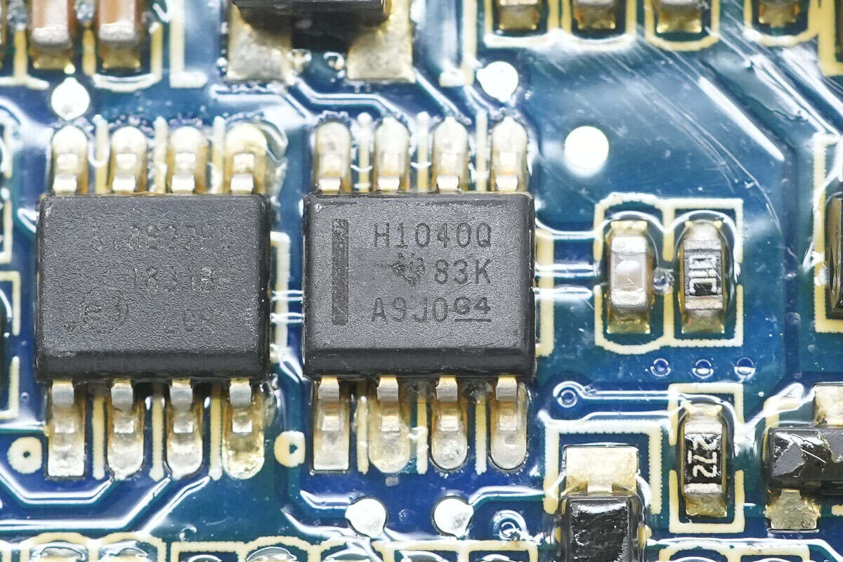
The CAN transceiver is from TI, marked with H1040Q, model SN65HVD1040-Q1. It is an automotive-grade, EMC-optimized CAN transceiver that meets automotive application standards, packaged in SOIC-8.
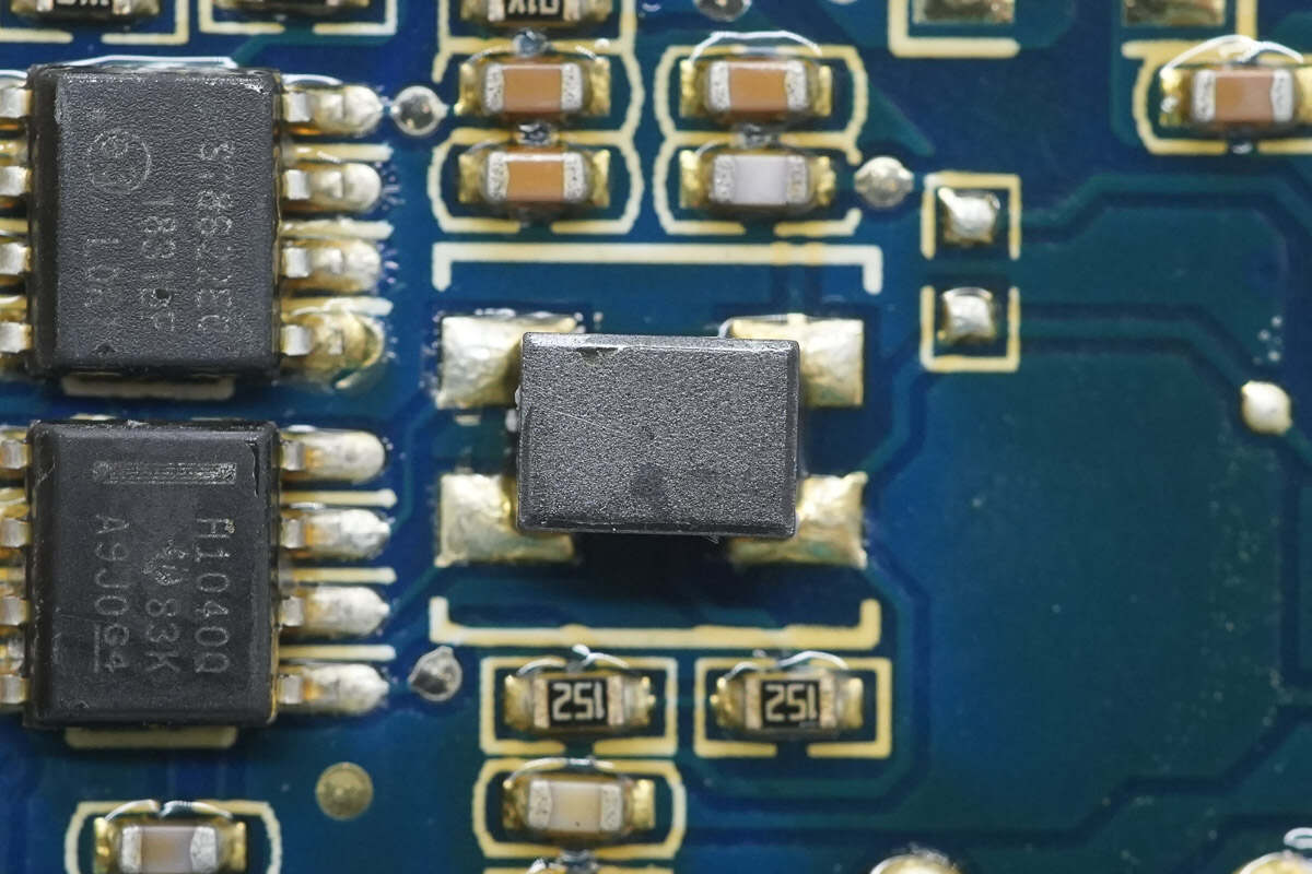
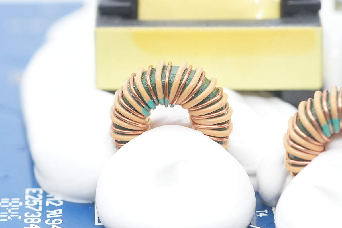
Close-up of the filter inductor.
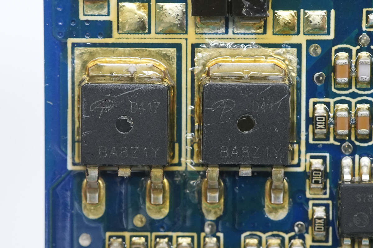
Two MOSFETs from AOS, model AOD417, are PMOS devices with a voltage rating of -30V and an on-resistance of 34mΩ, packaged in TO-252.
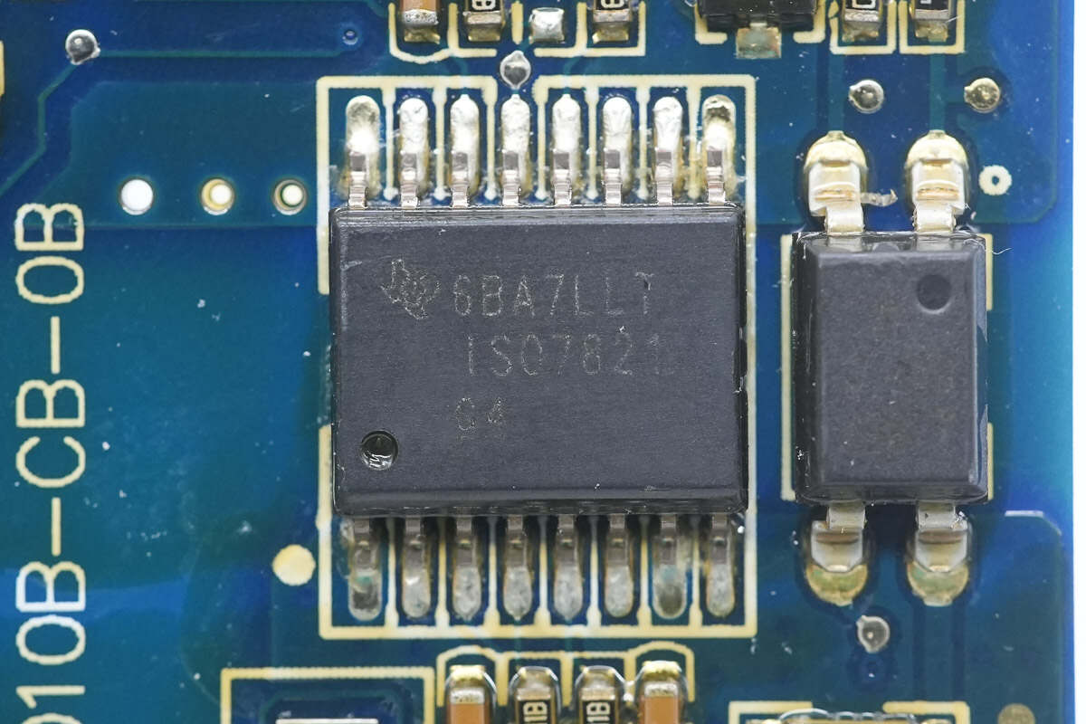
The isolation chip is from TI, model ISO7821. It is a high-performance enhanced dual-channel digital isolator, packaged in SOIC-16DW.
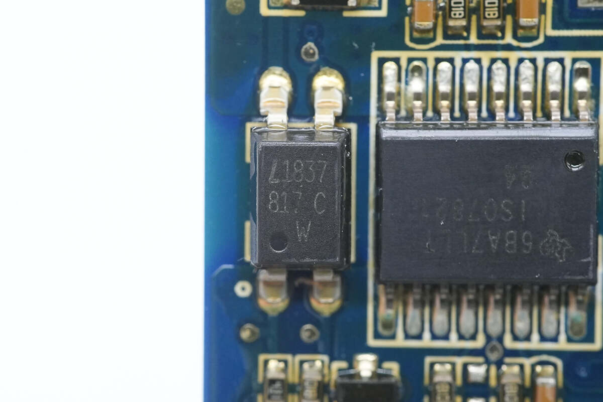
Close-up of the LITEON LTV-817C optocoupler.
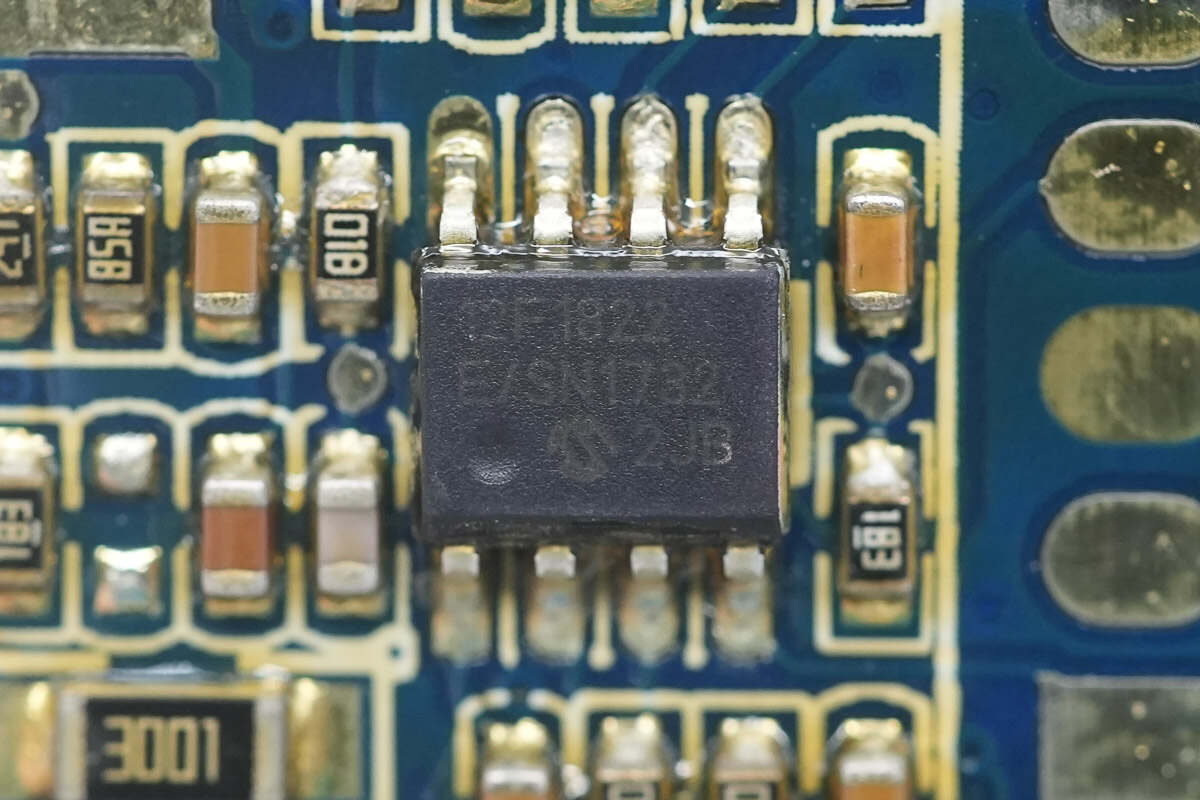
The MCU is from Microchip, model PIC12F1822. It is an 8-bit flash MCU with 3.5 KB of flash memory and 128 bytes of RAM, packaged in SOIC-8.
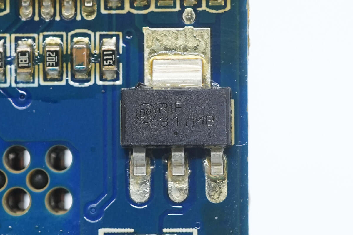
The regulator chip is from Onsemi, model LM317M. It supports an input voltage of up to 40V, an output voltage of up to 37V, and an output current of 500mA, packaged in SOT-223.
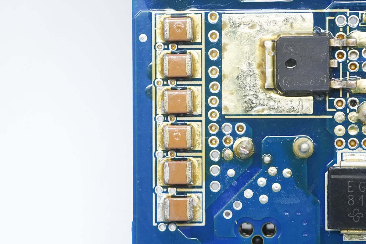
Close-up of the MLCC filter capacitors.
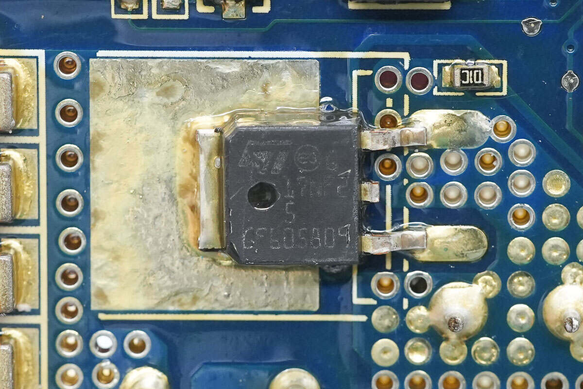
The MOSFET is from STMicro, model STD17NF25. It is an N-channel MOSFET with a voltage rating of 250V and an on-resistance of 140mΩ, packaged in DPAK.
The bottom of the buck inductor is reinforced with adhesive.
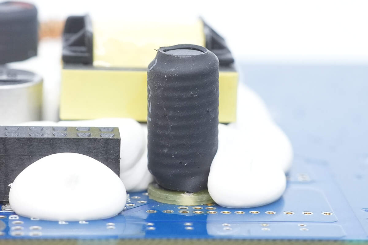
The filter inductor is covered with heat shrink tubing, and an insulating bakelite is installed at the bottom.
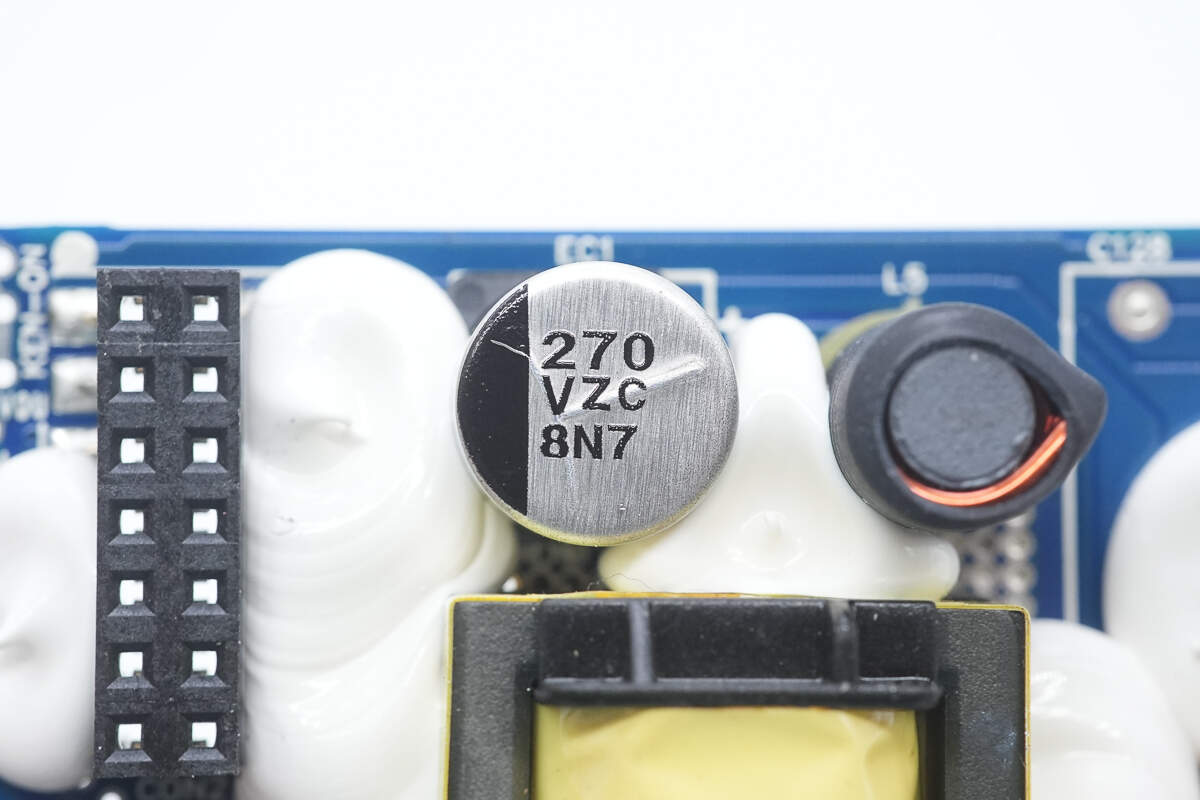
The filter capacitor is rated at 270μF, 35V.
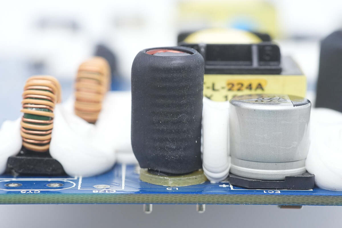
This filter inductor is also covered with heat shrink tubing, and an insulating bakelite is installed at the bottom.
Close-up of the isolation transformer used for driving MOSFETs.
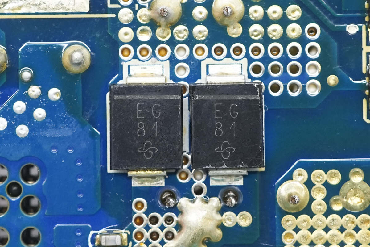
The two diodes are from VISHAY, marked with EG, model ES3G, are ultra-fast recovery diodes rated at 600V and 3A, packaged in SMC.
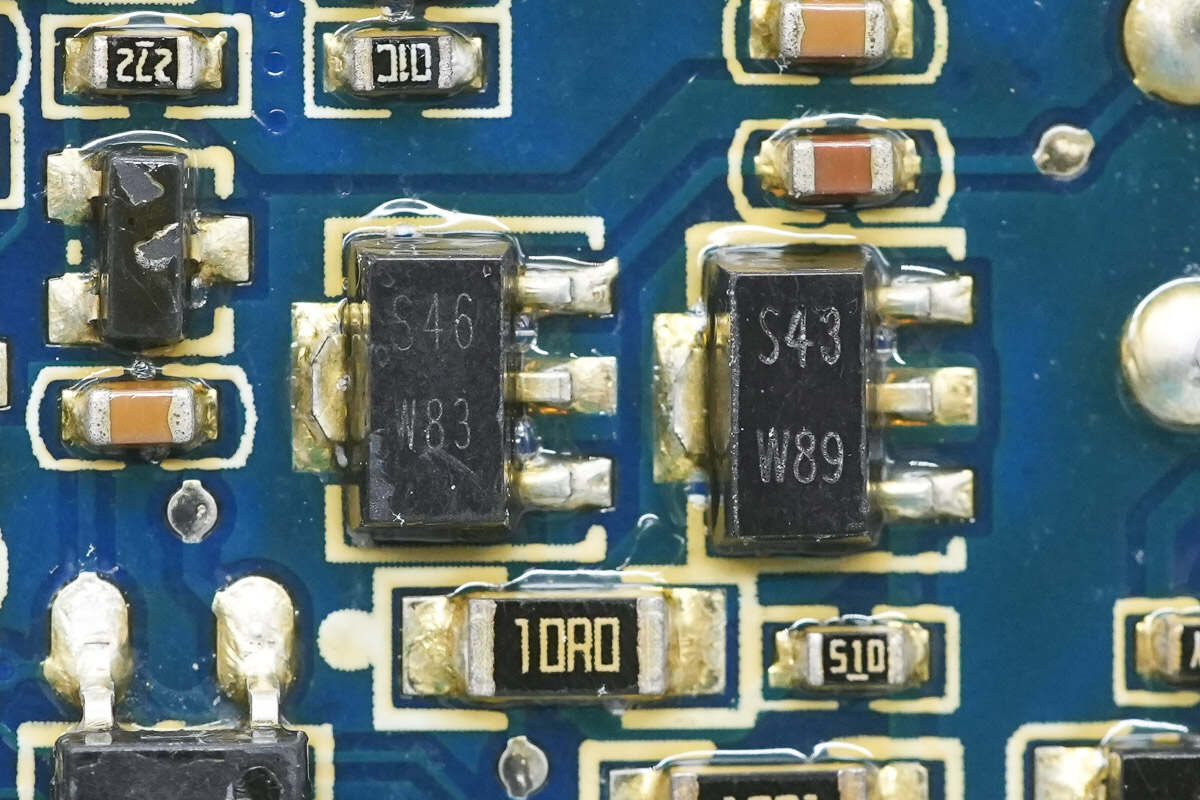
Close-up of two driver transistors.
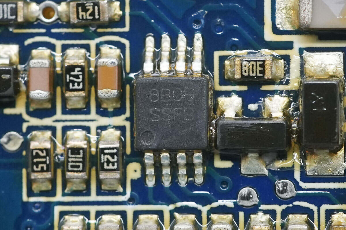
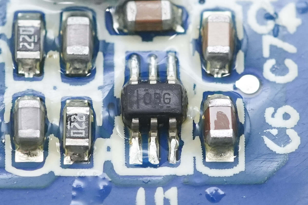
The PWM controller is from TI, marked with SSFB, model LM3478Q-Q1. It meets the AEC-Q100 standard, supports switching frequencies up to 1 MHz, features comprehensive protection functions, and is packaged in VSSOP-8.
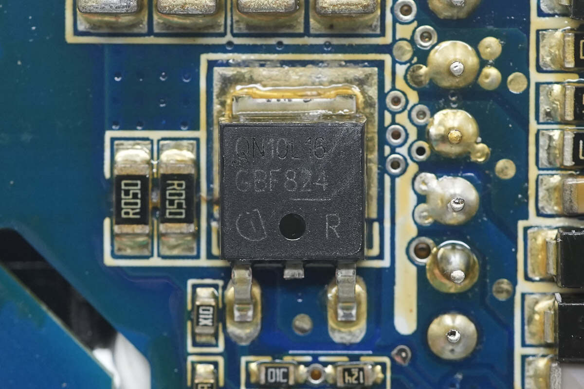
This MOSFET is from Infineon, marked with QN10L16, model IPD50N10S3L-16. It is an N-channel MOSFET with a voltage rating of 100V and an on-resistance of 15mΩ, packaged in TO252-3-11.

Close-up of the MLCC filter capacitor.
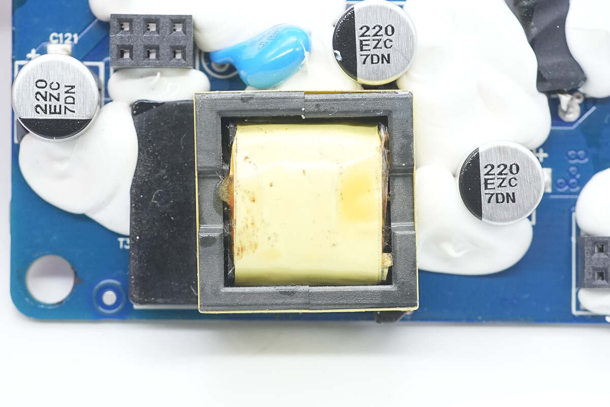
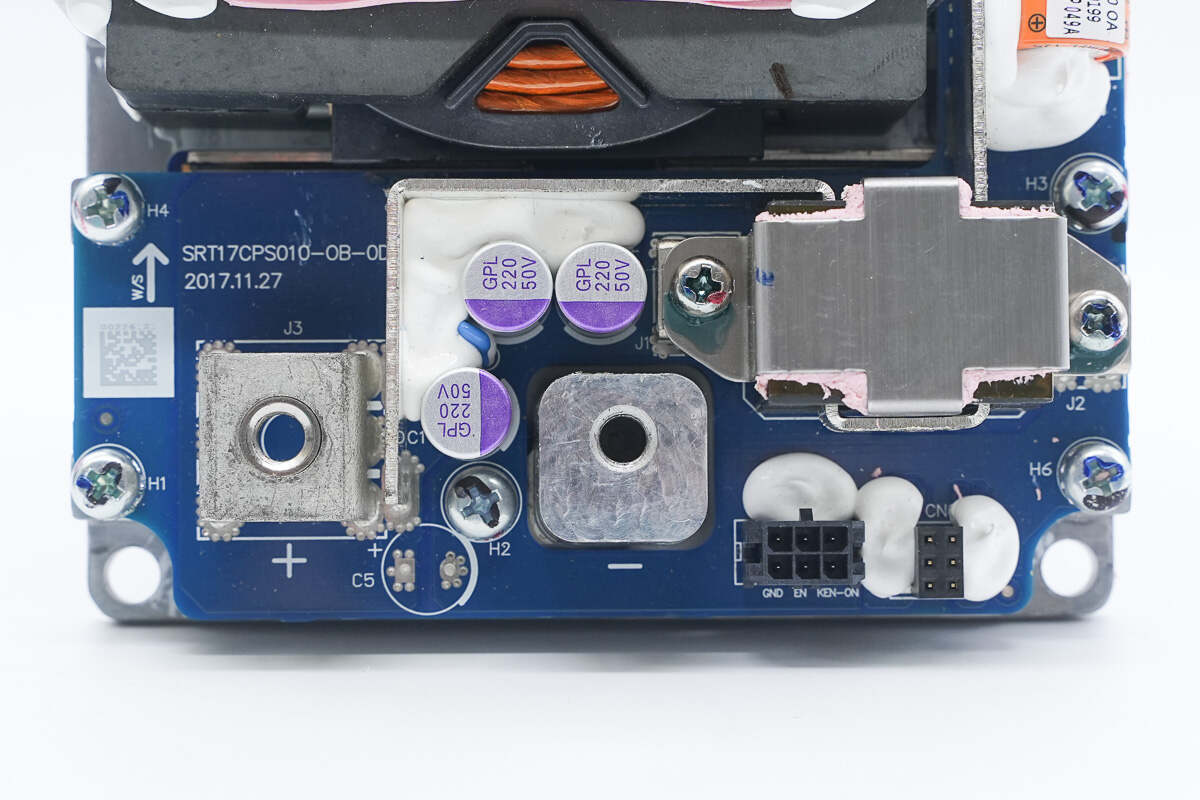
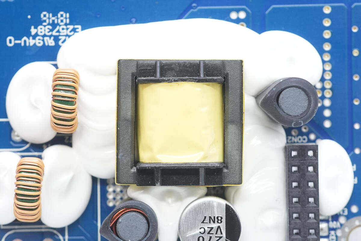
The transformer is reinforced with adhesive, with three filter capacitors (each rated 220μF, 25V) positioned around its edges.
The filter inductor is insulated with heat shrink tubing and reinforced with adhesive.
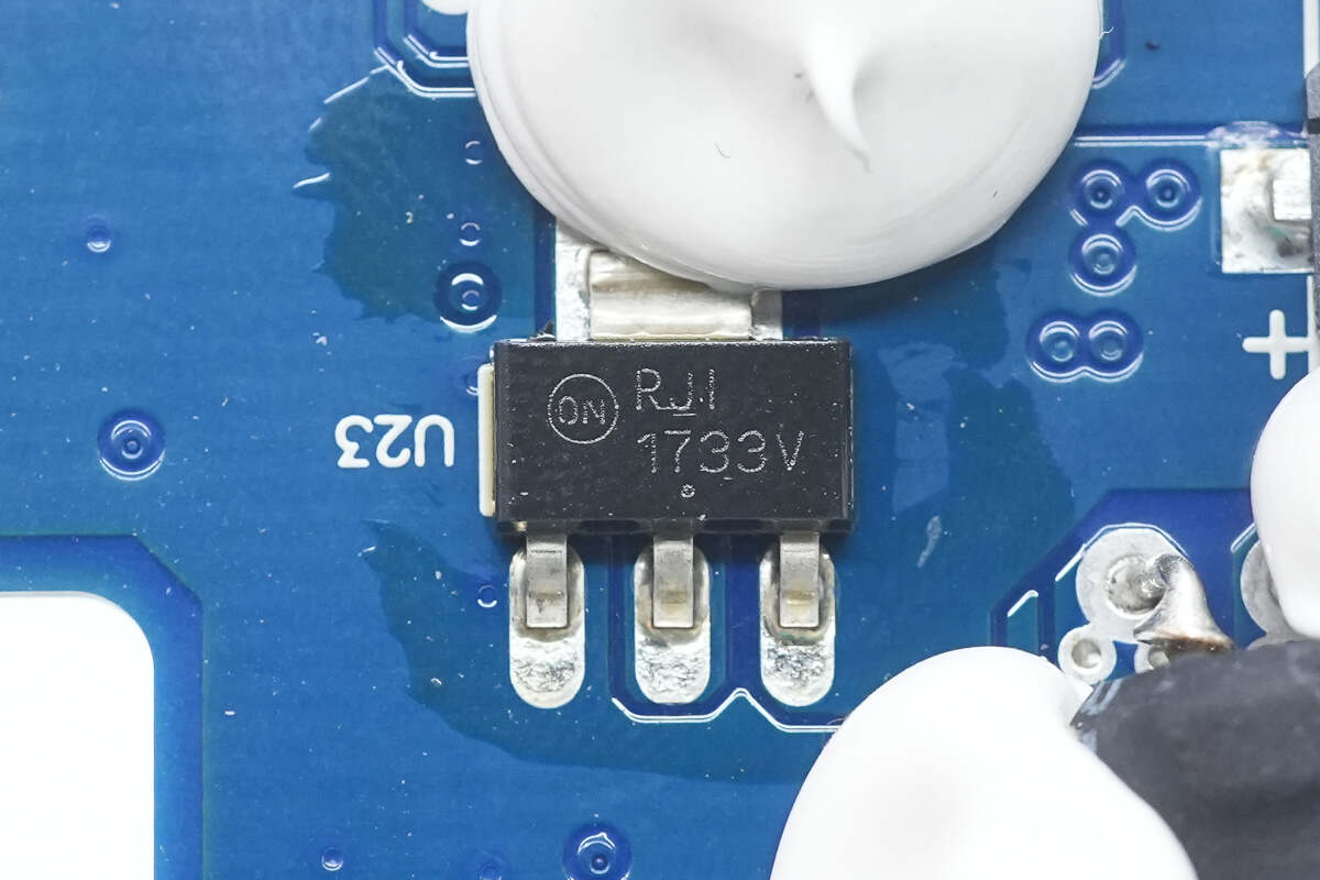
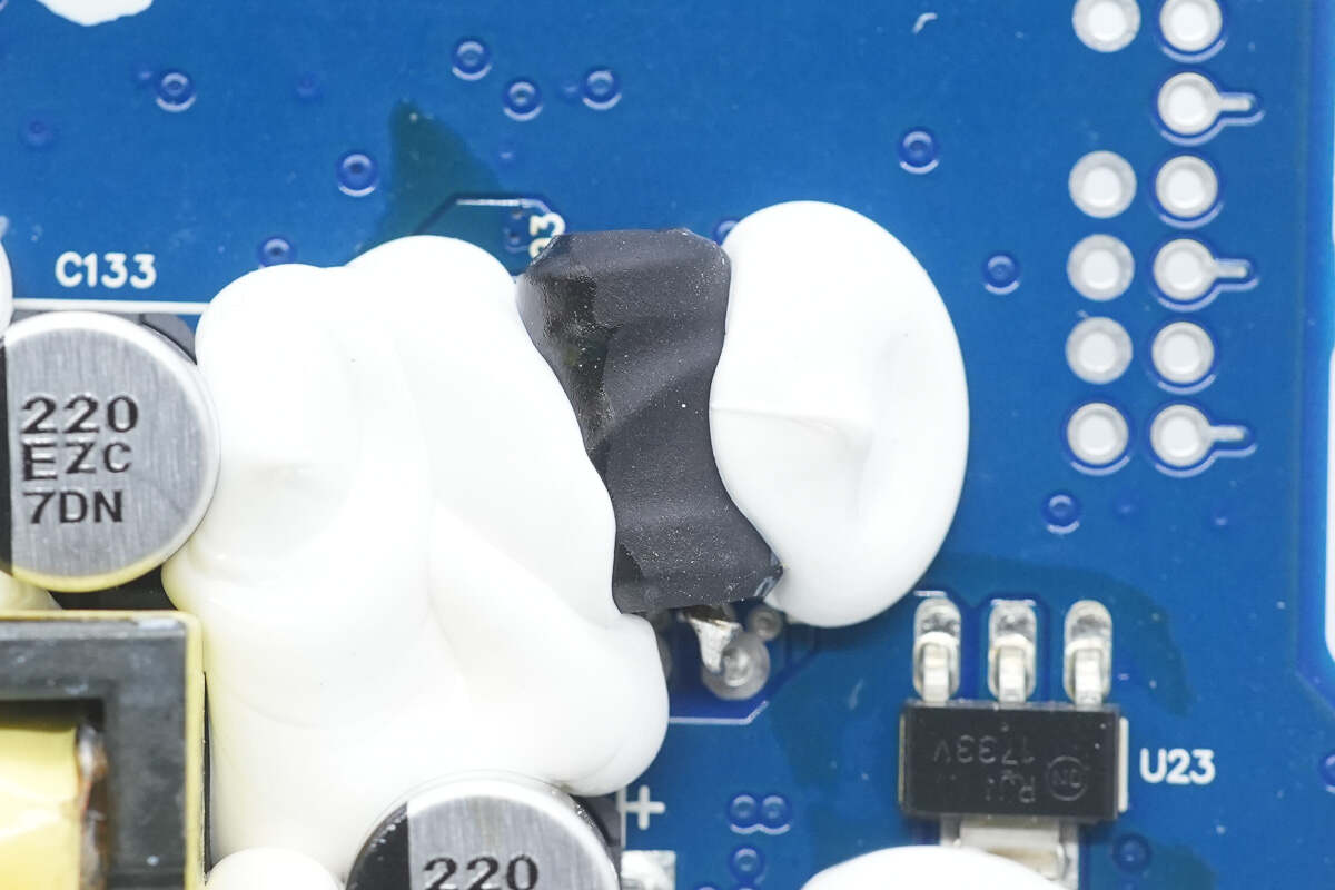
The regulator chip is from Onsemi, marked with 1733V, model NCV1117ST33. It supports an input voltage of up to 20V, outputs 3.3V, delivers 1A of current, and is packaged in SOT-223.
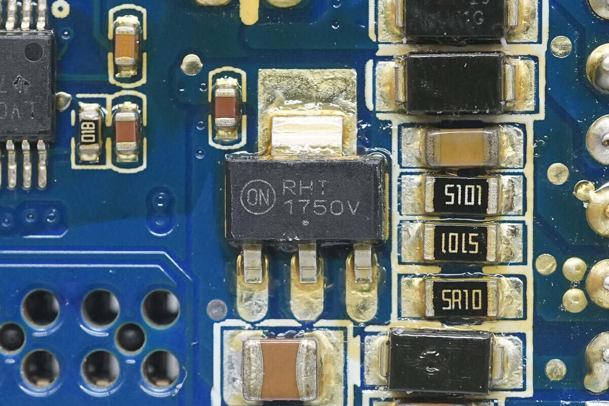
Another regulator chip, marked with 1750V, model NCV1117ST50, provides a 5V output voltage.
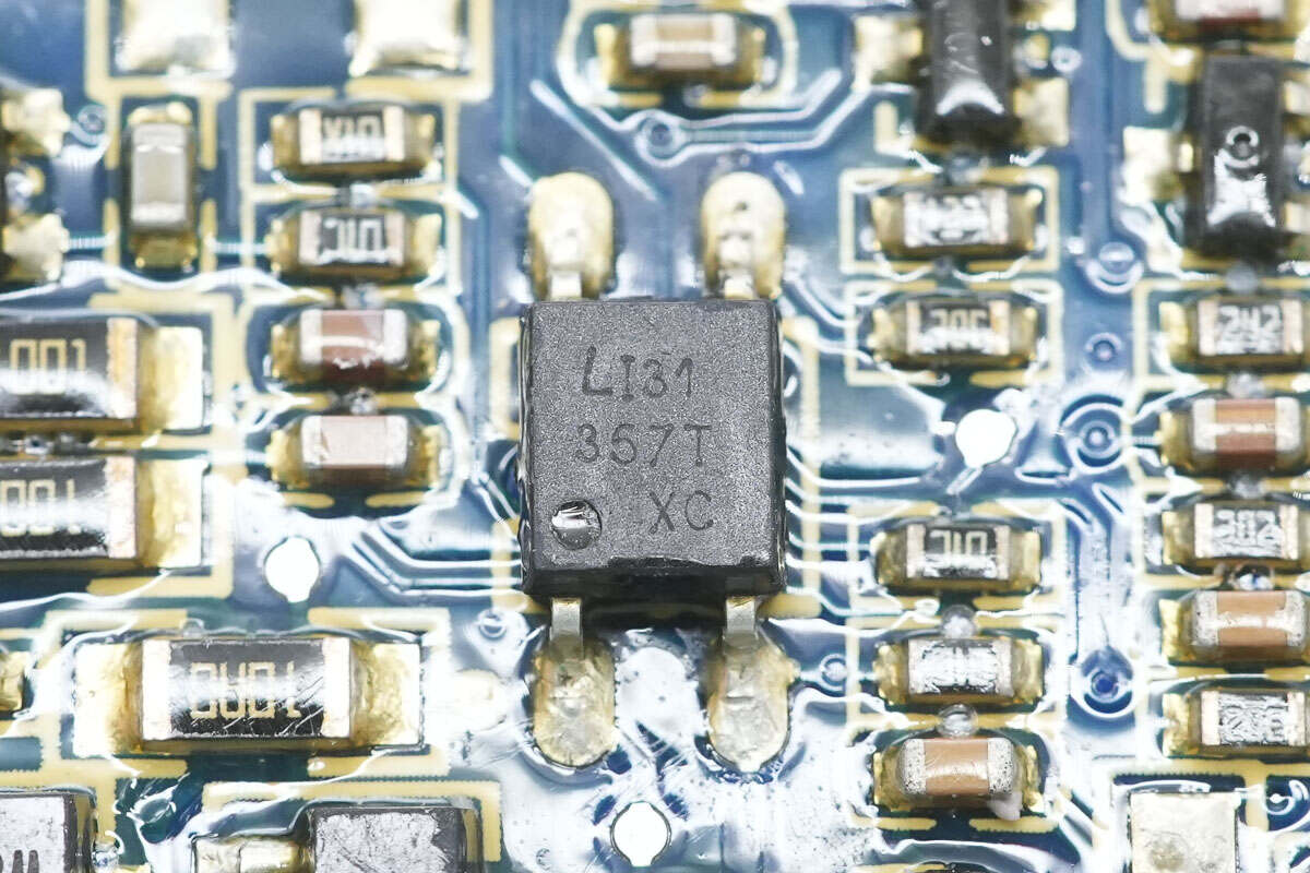
There are a total of three LITEON LTV-357T optocouplers.
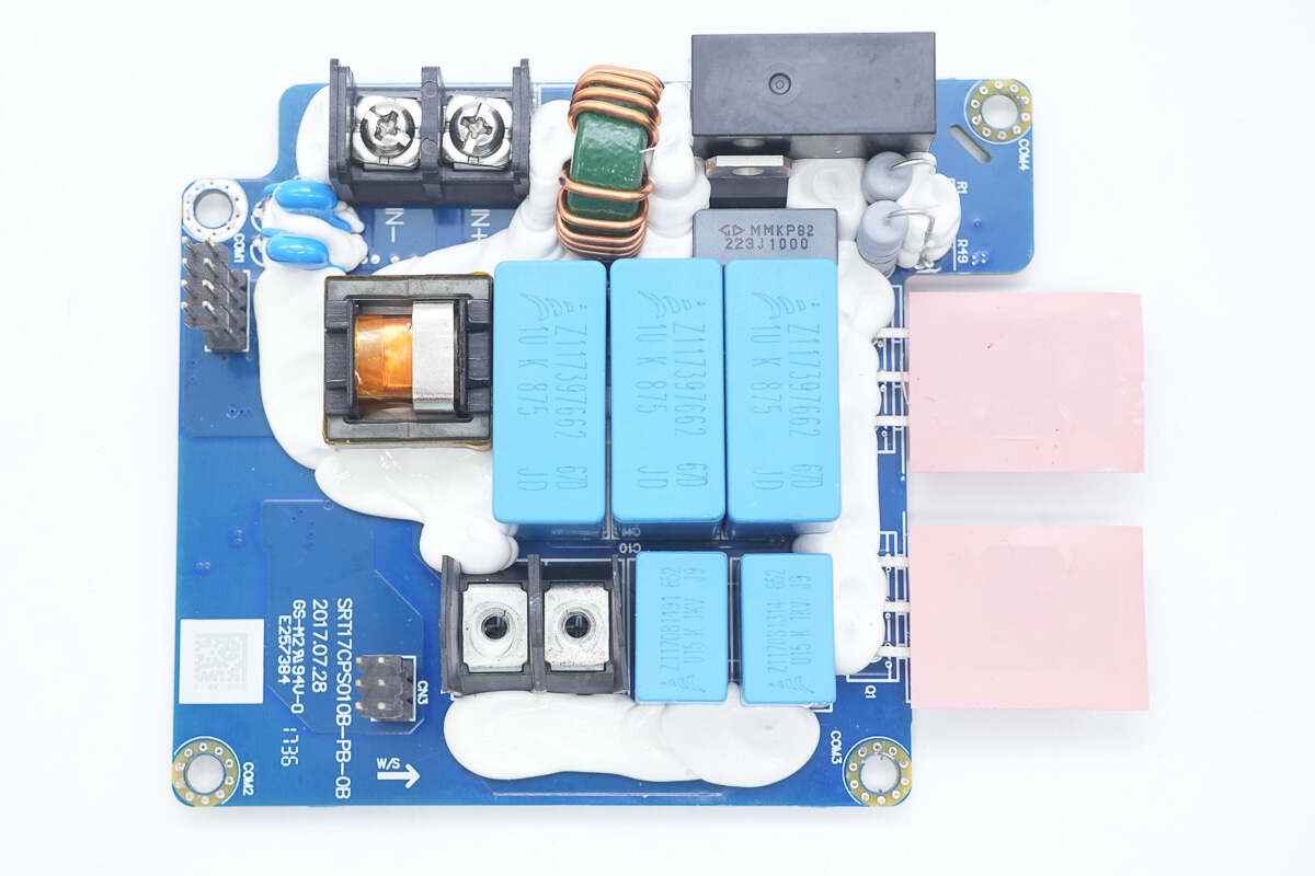
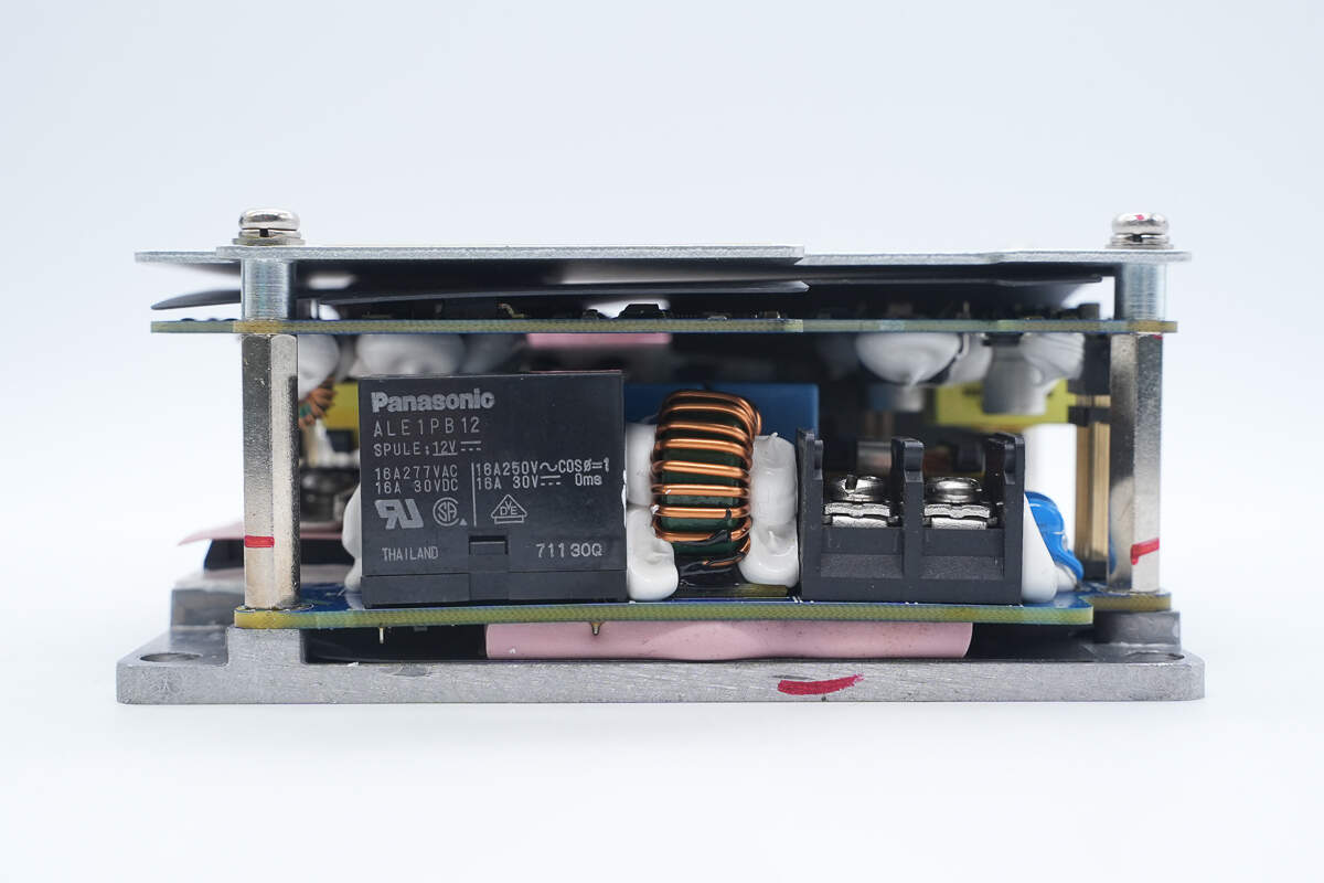
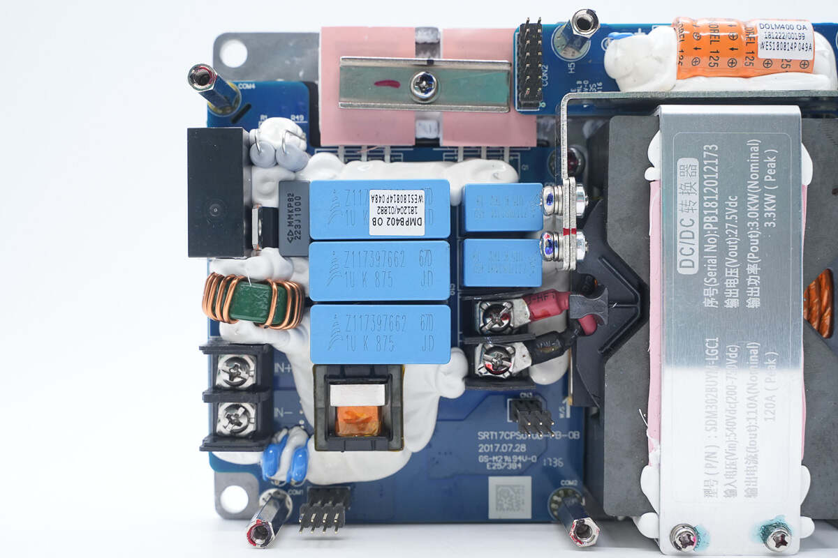
The bottom PCB features terminal blocks, a common mode choke, a relay, a current transformer, film capacitors, and resonant capacitors. Two silicon carbide MOSFETs are located at the edge.
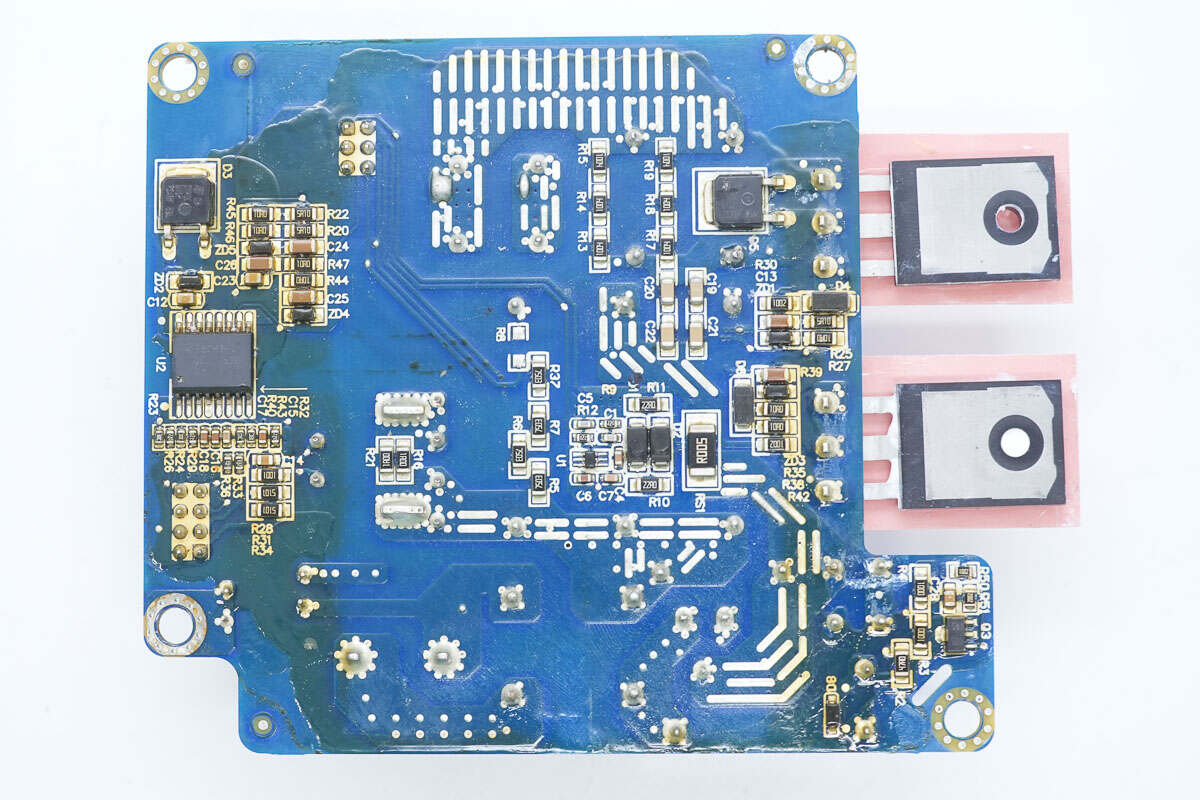
The other side has an isolation driver, a current-sensing chip, and diodes.
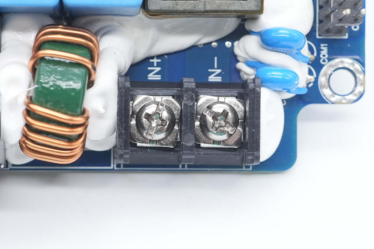
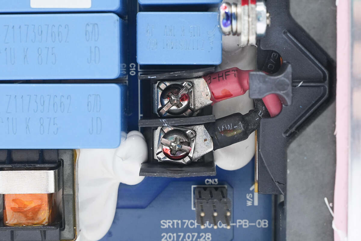
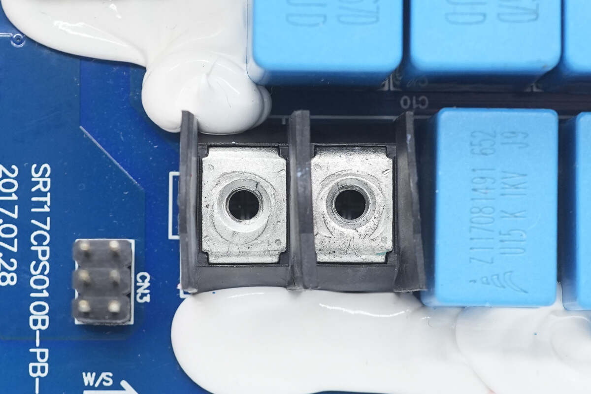
The input terminals are fixed with screws.
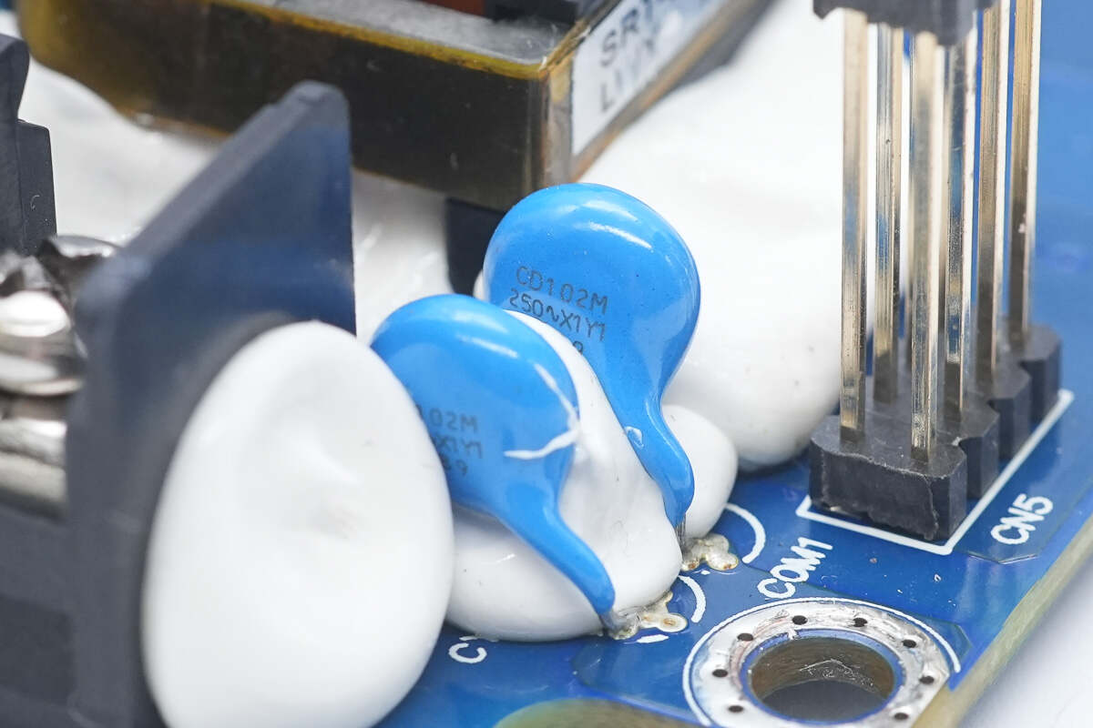
Close-up of two blue Y capacitors.
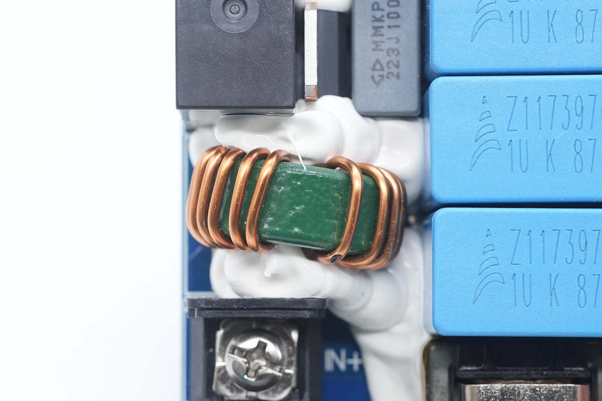
Both sides of the filter inductor are reinforced with adhesive.
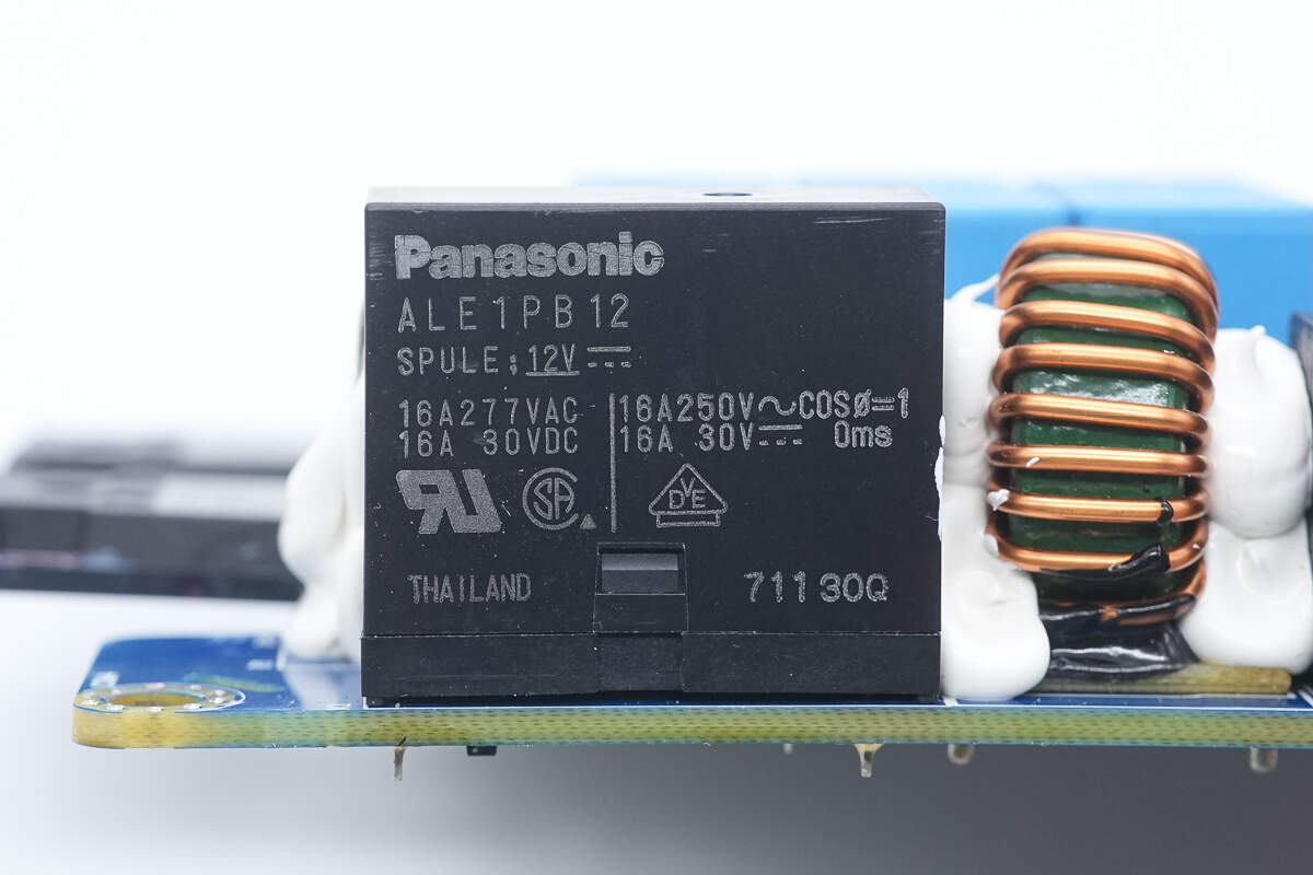
The relay is from Panasonic, model ALE1PB12, with a contact rating of 16A and a coil voltage of 12V.
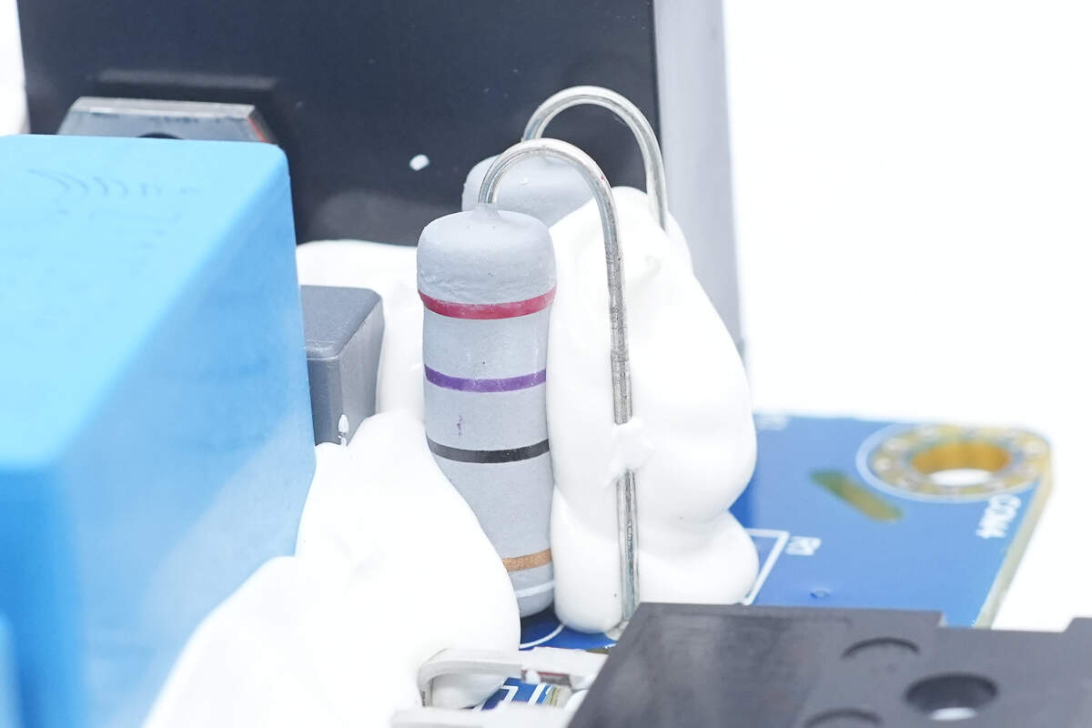
Two carbon film resistors are reinforced with adhesive.
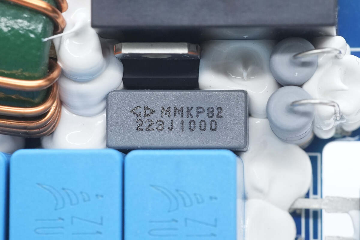
The film capacitor is from Faratronic, rated at 0.022μF, 1 kV.
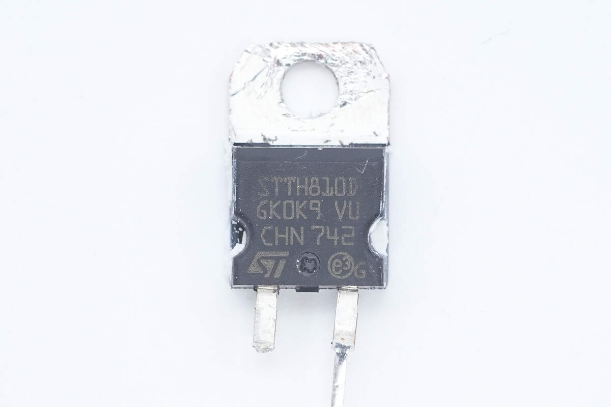
The ultra-fast recovery diode is from STMicro, model STTH810, rated at 8A and 1000V, packaged in TO-220AC.
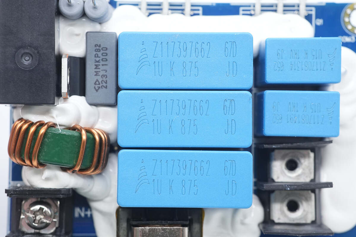
The film capacitors are from TDK, each rated at 1μF, 875V.
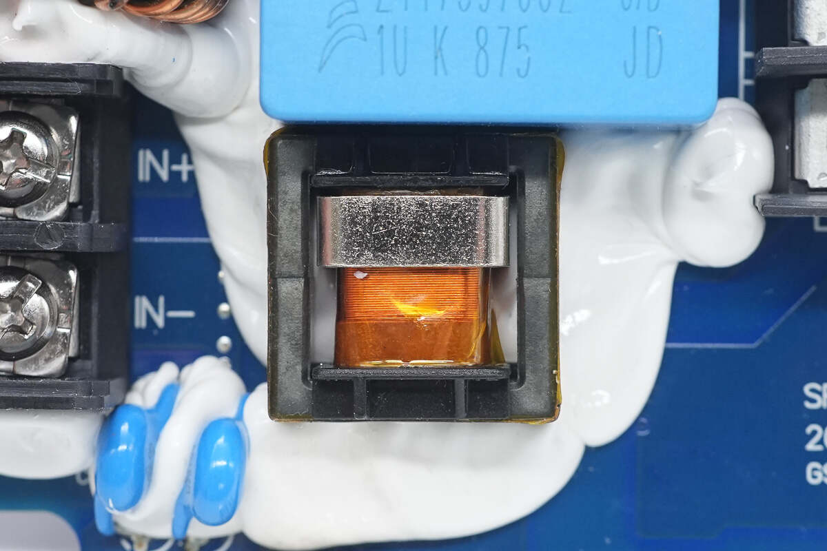
The current transformer is reinforced with adhesive.
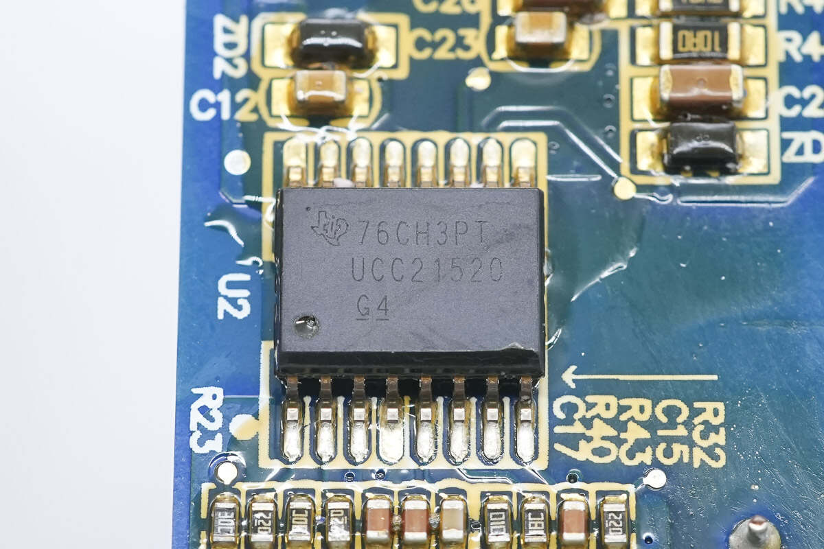
The isolation driver is from TI, model UCC21520. It is an isolated dual-channel gate driver with a 4A peak sourcing current and 6A peak sinking current. It can drive MOSFETs, IGBTs, and silicon carbide MOSFETs, supports switching frequencies up to 5 MHz, and is packaged in SOIC-16DW.
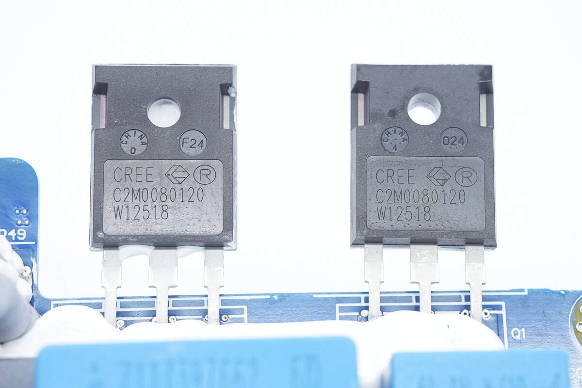
The silicon carbide MOSFETs are from Wolfspeed, model C2M0080120D. They are N-channel enhancement-mode devices with a voltage rating of 1200V and an on-resistance of 80mΩ, packaged in TO-247-3.
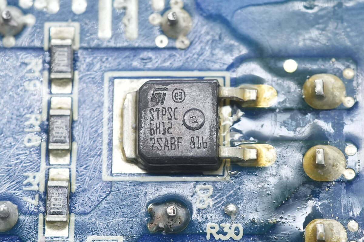
The silicon carbide diode is from STMicro, model STPSC6H12. It is rated at 1200V and 6A, and comes in a DPAK package.
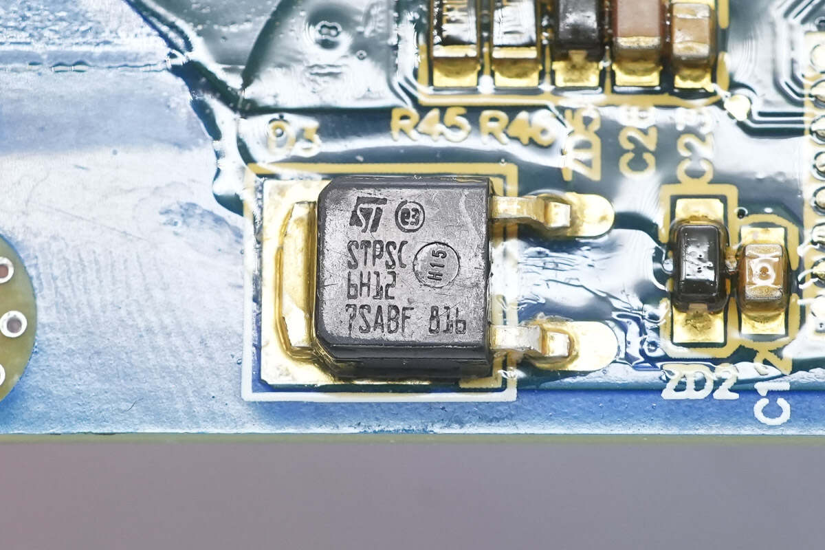
Another silicon carbide diode has the same model.
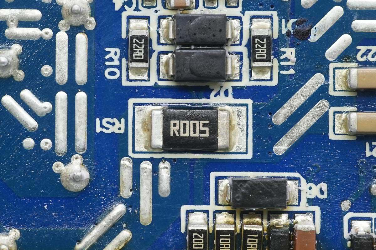
Close-up of the 5mΩ current sense resistor.
The current sensing chip is from TI, marked with OBG, model INA199A1. It is a bidirectional, zero-drift current shunt monitor with a voltage rating of 26V, packaged in SC70.
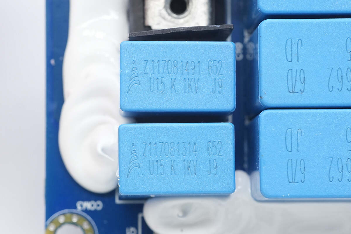
Two resonant capacitors, each rated at 0.15 μF, 1 kV.
Close-up of the terminal blocks connected to the transformer.

Close-up of the pin header connecting to the upper PCB.
The transformer clamp is secured with screws.
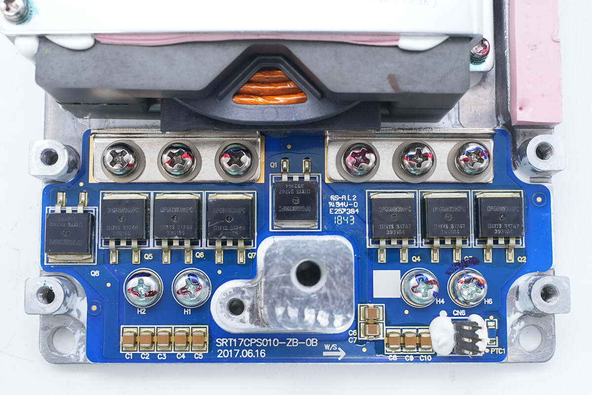
The aluminum substrate is secured with screws and equipped with rectifiers and filter capacitors.
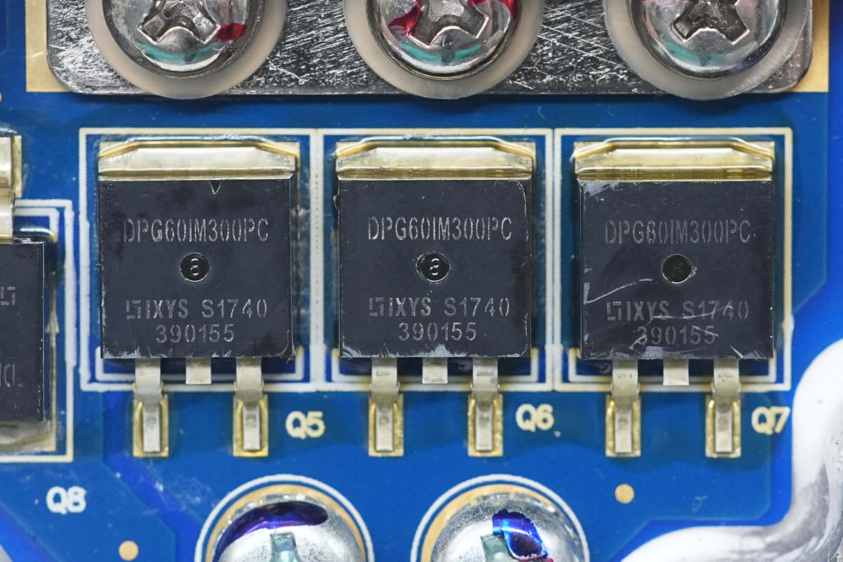
The rectifiers are from Littelfuse, model DPG60IM300PC. They are fast recovery diodes rated at 300V and 60A, packaged in TO-263.
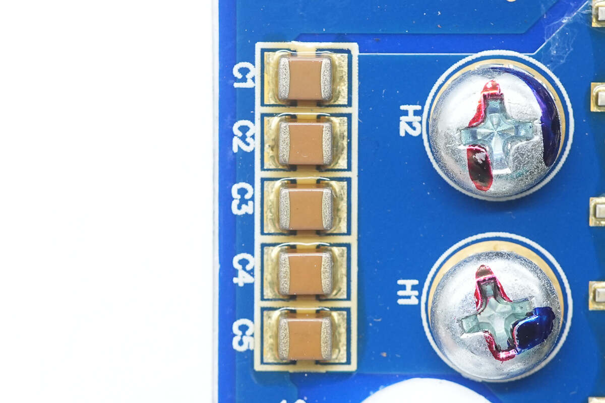
Close-up of the MLCC filter capacitors.
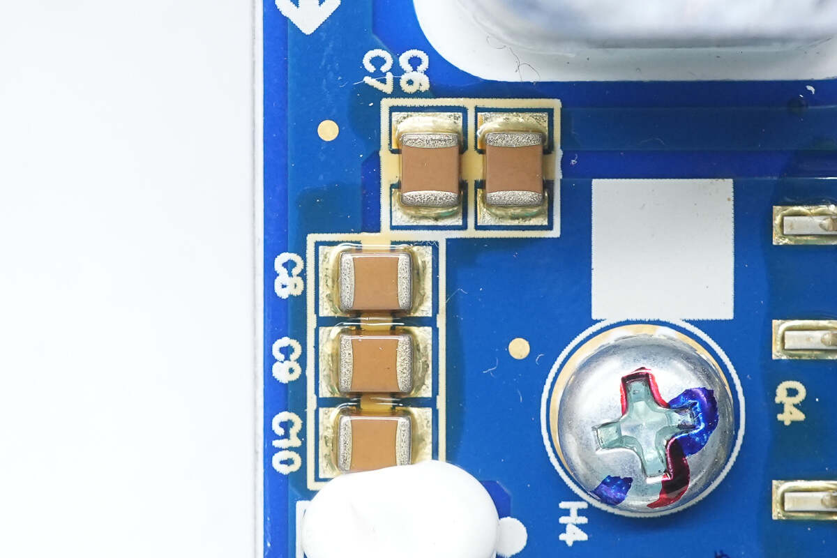
Close-up of another set of MLCC filter capacitors.
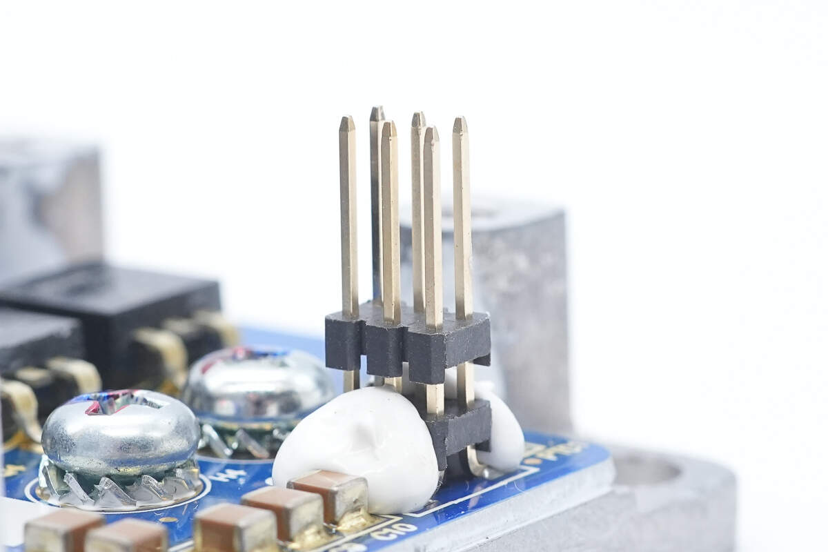
The connecting pin headers are soldered in place and reinforced with adhesive at the base.
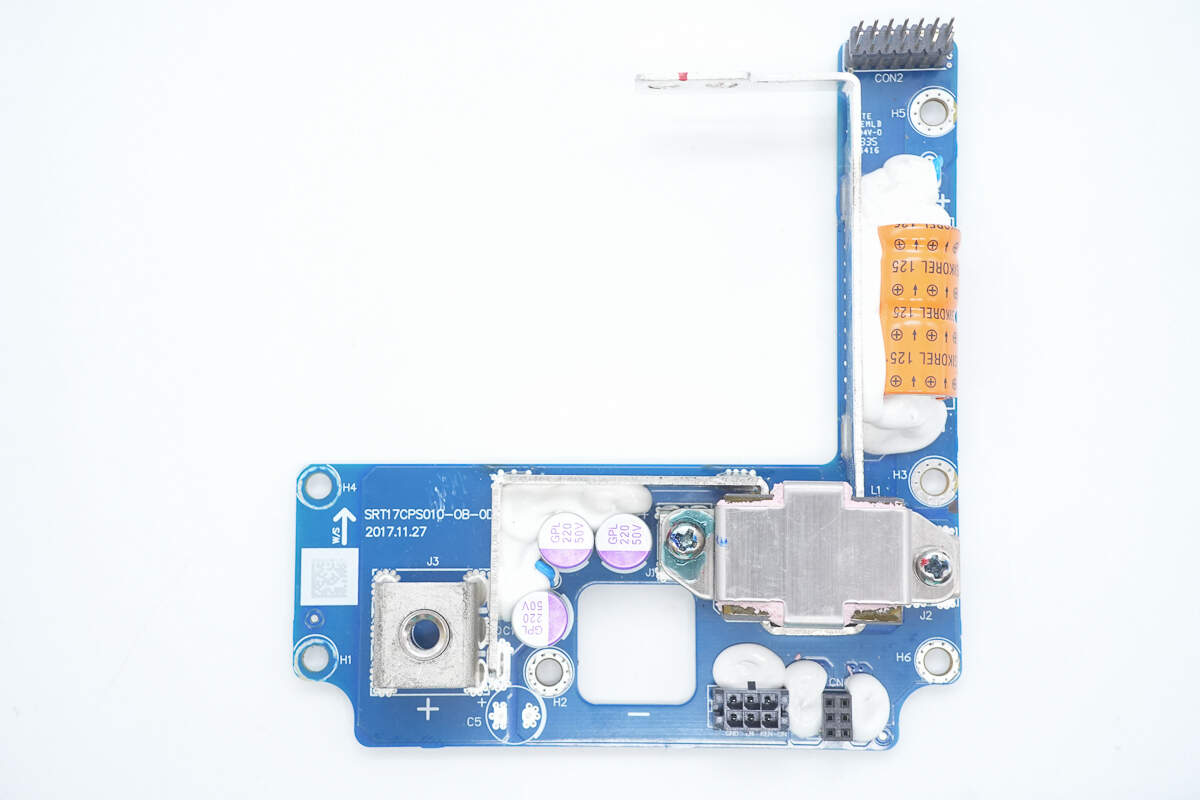
The positive terminal PCB features filter capacitors, a filter inductor, and a terminal post.
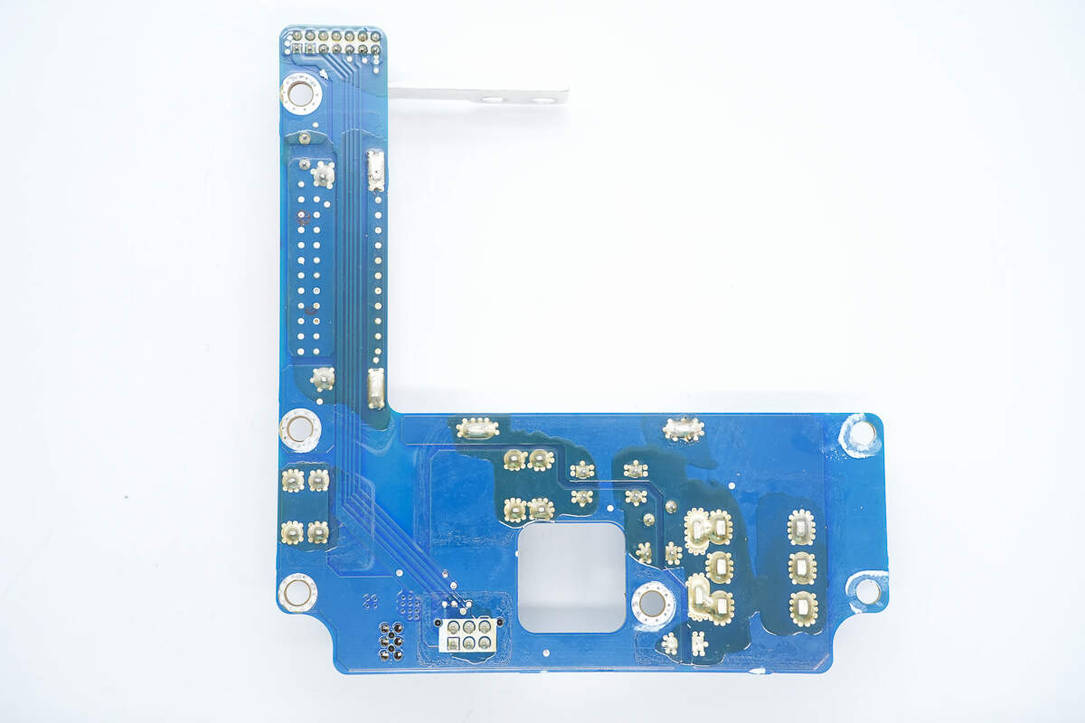
There are no components on the back.
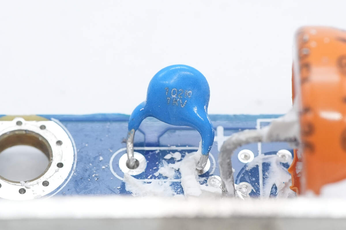
The blue ceramic capacitor is rated at 1000 pF, 1 kV.
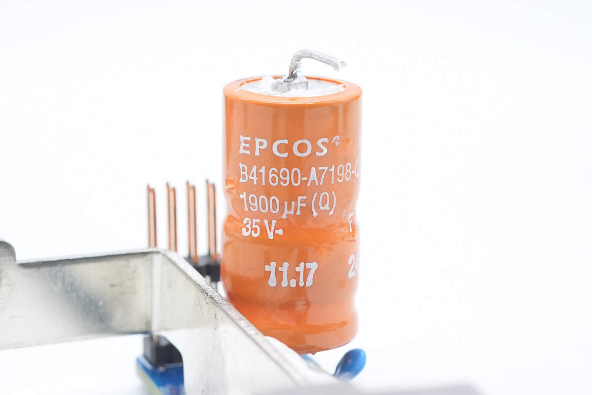
The filter electrolytic capacitor is from TDK, rated at 1900 μF, 35V.
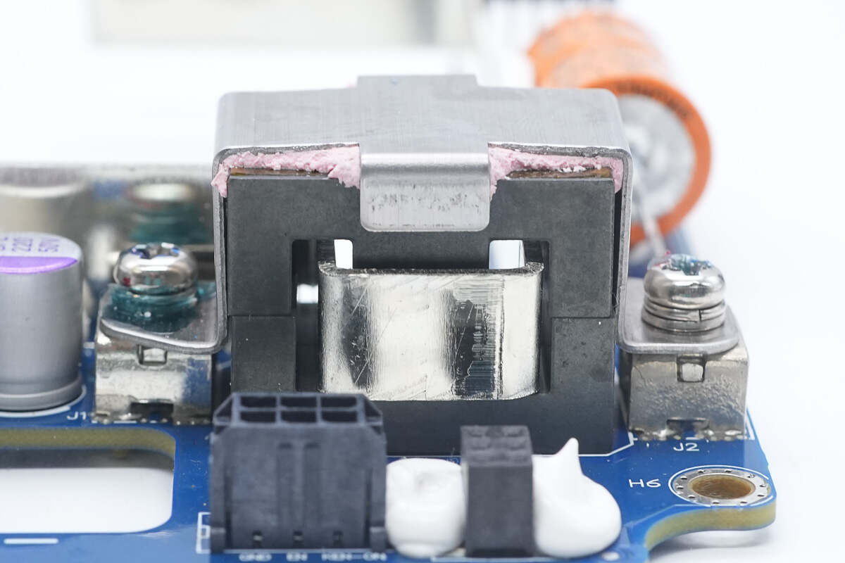
The filter inductor core is secured with a clamp plate.
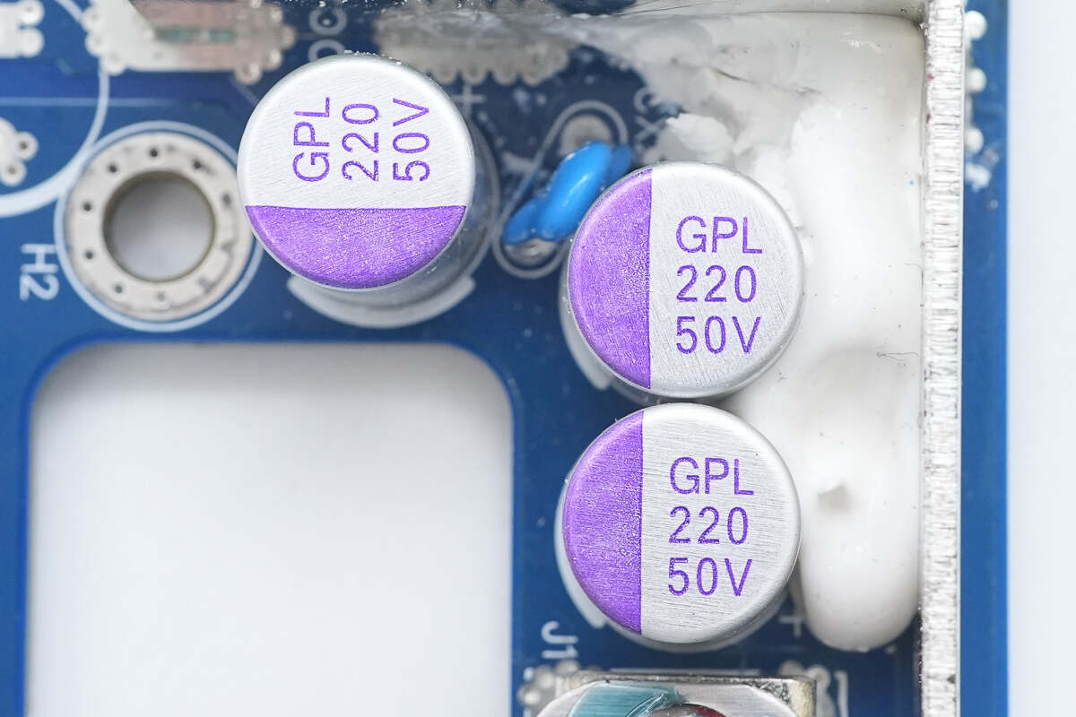
The output filter capacitor is from GEMCON, part of the GPL series of solid capacitors, rated at 220μF, 50V.
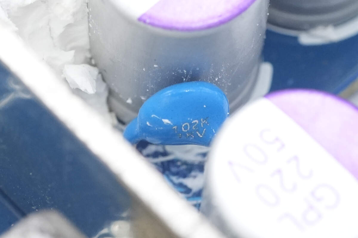
The blue ceramic capacitor is rated at 1000pF, 1kV.
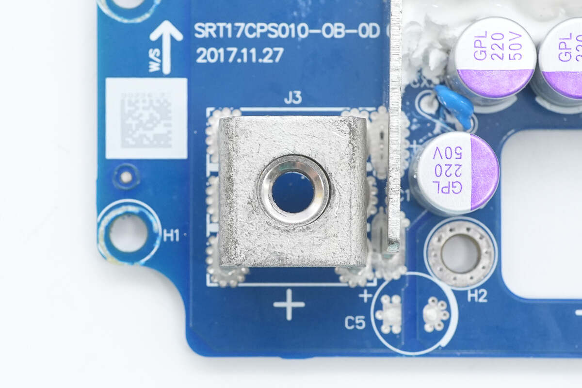
The positive terminal post is connected via soldering.
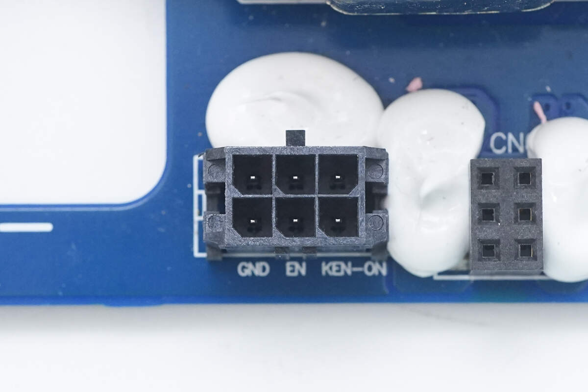
The connector is reinforced with adhesive.
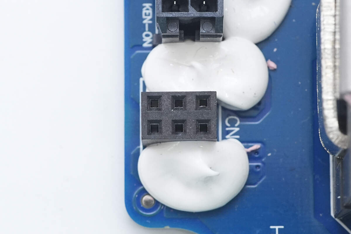
The pin header socket is also reinforced with adhesive.
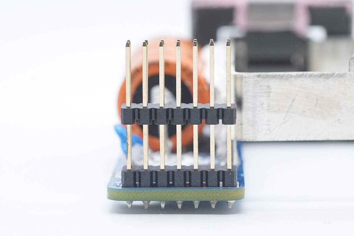
Close-up of the pin header.
Well, those are all components of the Foton Aumark 3kW DC-DC Converter.
Summary of ChargerLAB
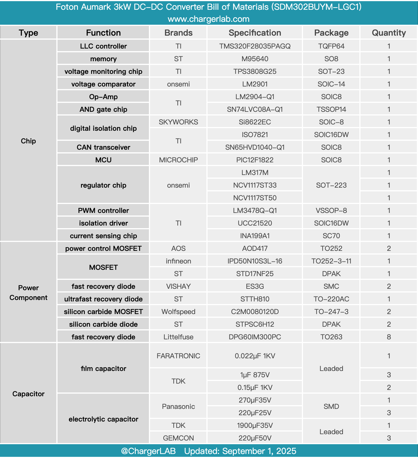
Here is the component list of the Foton Aumark 3kW DC-DC Converter for your convenience.
It features an aluminum alloy enclosure for efficient heat dissipation. It supports a DC input voltage range of 200–750V and provides a 27.5V output. The rated output current is 110A, with a rated power of 3kW. Both input and output are connected via terminal blocks, and communication terminals are also provided.
After taking it apart, we found that it uses an LLC architecture, controlled by a TI TMS320F28035PAGQ controller. A UCC21520 isolation driver drives Wolfspeed C2M0080120D silicon carbide MOSFETs, paired with STMicro STPSC6H12 silicon carbide diodes. The output rectifiers are Littelfuse DPG60IM300PC.
The module is composed of multiple PCBs. A thermal pad is placed between the PCBA module and the aluminum alloy base to enhance heat dissipation. The output rectifiers are soldered onto the aluminum substrate for improved thermal performance. Automotive-grade components are used throughout, with capacitors, inductors, and other parts reinforced with adhesive, reflecting solid build quality and reliable materials.
Related Articles:
1. Teardown of UGREEN Nexode 20000mAh 130W Power Bank with Built-in USB-C Cable (PB723)
2. Teardown of Supermicro 720W 1U Redundant Power Supply (PWS-721P-1R)
3. Teardown of UGREEN Nexode 20000mAh 165W Power Bank with Retractable USB-C Cable (PB726)