Introduction
As one of the oldest and most iconic automotive brands in the United States, Ford has long been recognized for its engineering legacy. Its luxury sub-brand, Lincoln, also enjoys global renown. In recent years, Ford has faced growing competition in the electric vehicle market, yet it remains a key representative of American car manufacturing.
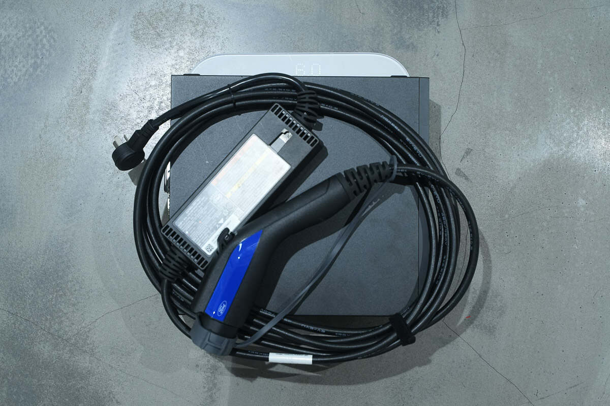
In this teardown, we take a closer look at a portable 1760W EV charger from Ford. Featuring a classic integrated design, this charging unit comes with a total cable length of approximately 6.8 meters, making it ideal for in-vehicle storage and emergency use. Equipped with a 10A plug and supporting an 8A charging current, it delivers a maximum output of 1760W.
Product Appearance

The Ford 1760W EV charger comes with a storage bag, making it easy to carry and transport.
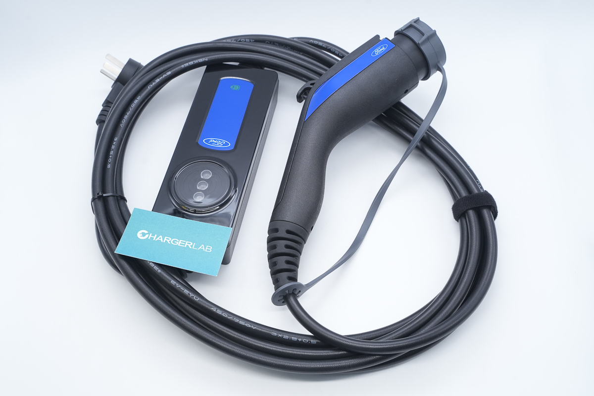
It features a classic design consisting of three main parts: the charging connector, the control box, and the cable.
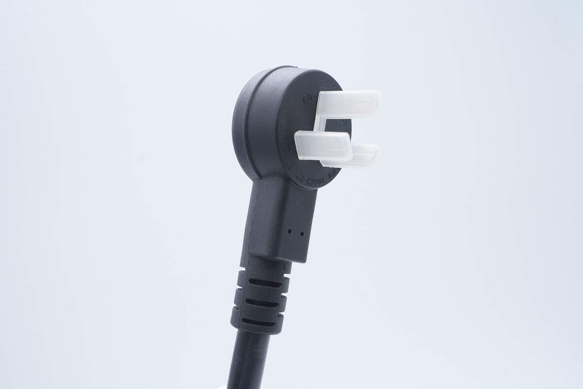
The AC input plug is protected by a plastic housing.
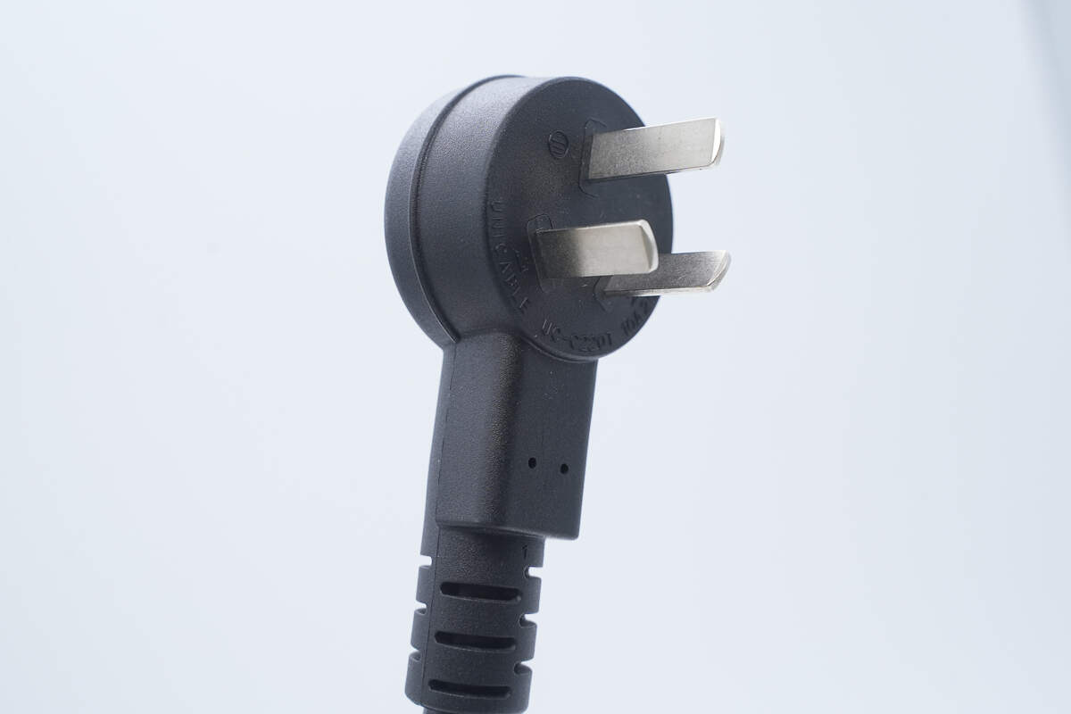
The edge of the plug housing features a raised design to make plugging and unplugging easier.
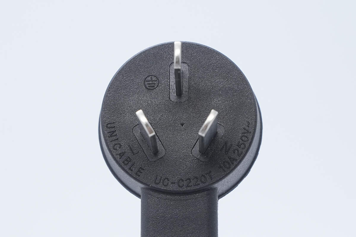
It is rated at 10A, 250V~.
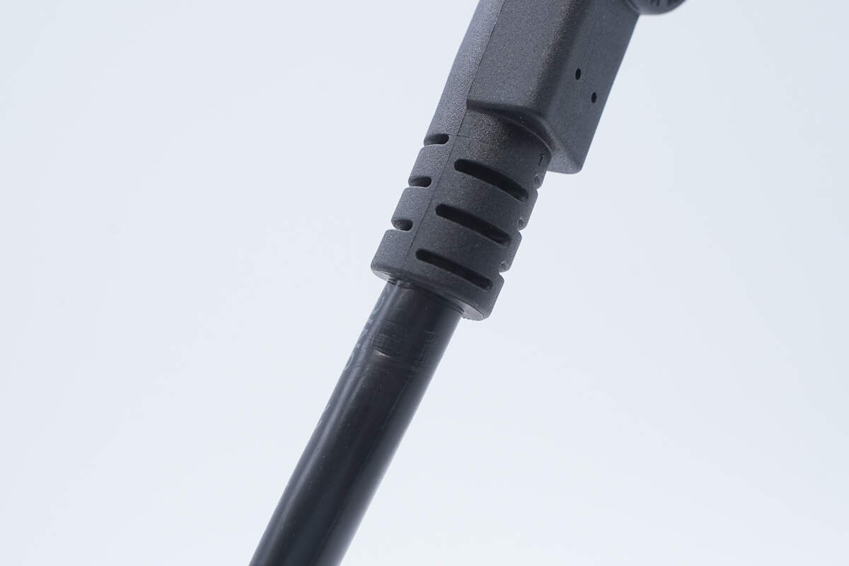
The connection between the plug and the cable is reinforced with a strain relief design to prevent bending and wear.
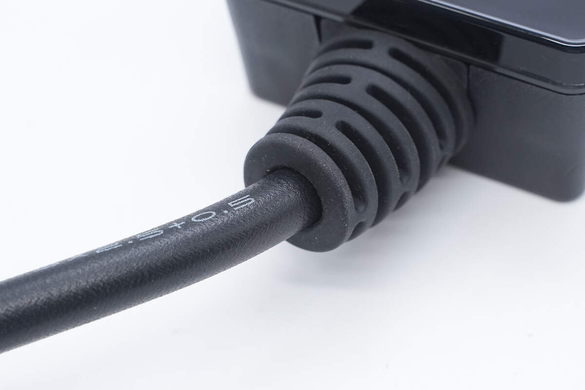
Both ends of the control box’s cables are equipped with strain relief designs.
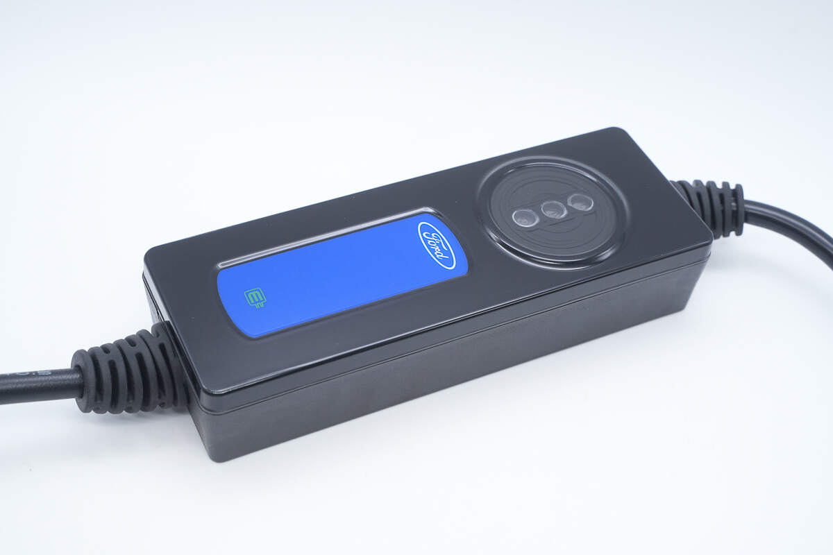
The control box features a flame-retardant PC housing, with a blue decorative panel on top and three indicator lights.

The power-on, fault, and power outlet check indicator lights are labeled accordingly. A snapshot taken at the moment of powering on shows the lights as green, red, and orange, respectively.
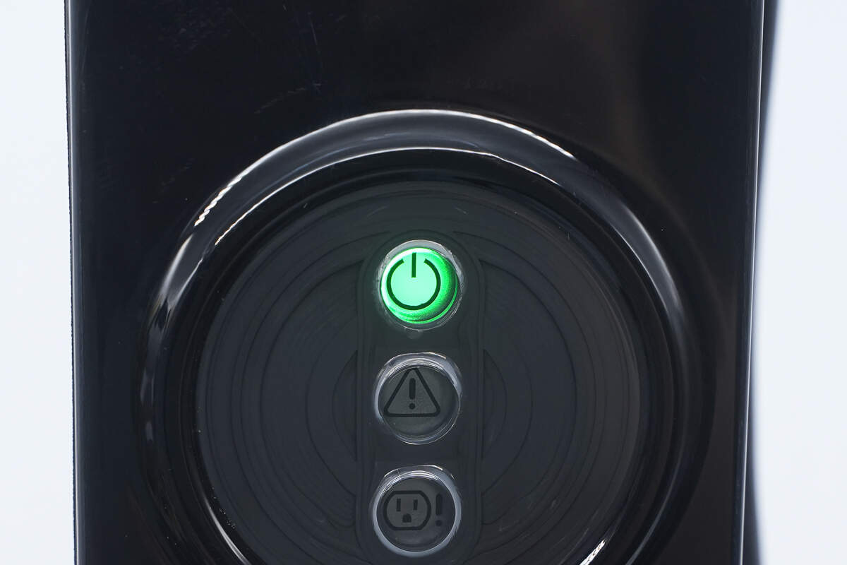
Under normal power-on conditions, the power-on indicator light stays solid, while the other two indicator lights remain off.

The blue decorative panel is recessed and features the Ford logo along with a plug icon.
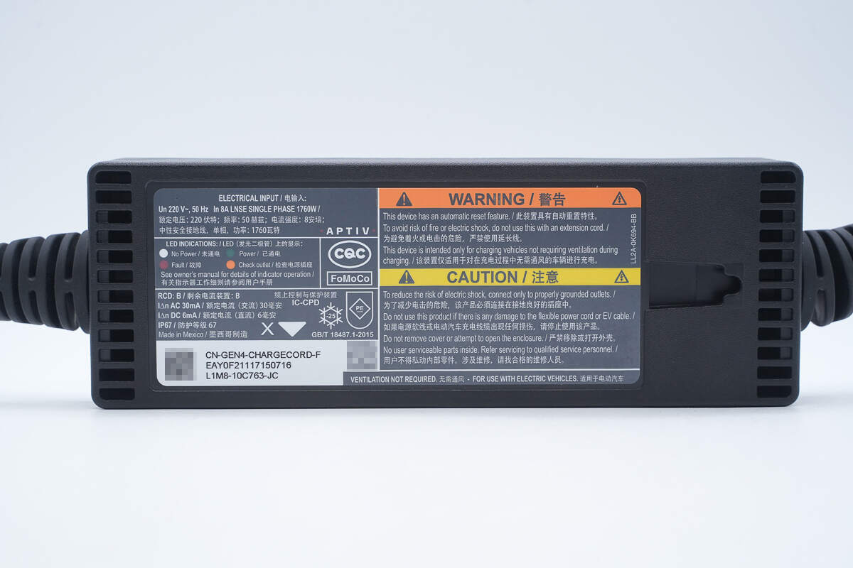
A product label is attached to the bottom.
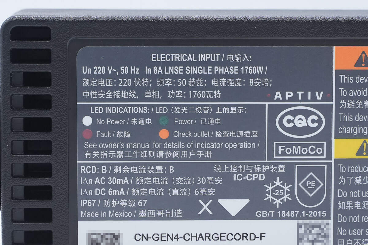
Rated voltage: 220V\~
Frequency: 50Hz
Current: 8A
Power: 1760W
Protection rating: IP67
It has passed the CQC certification.
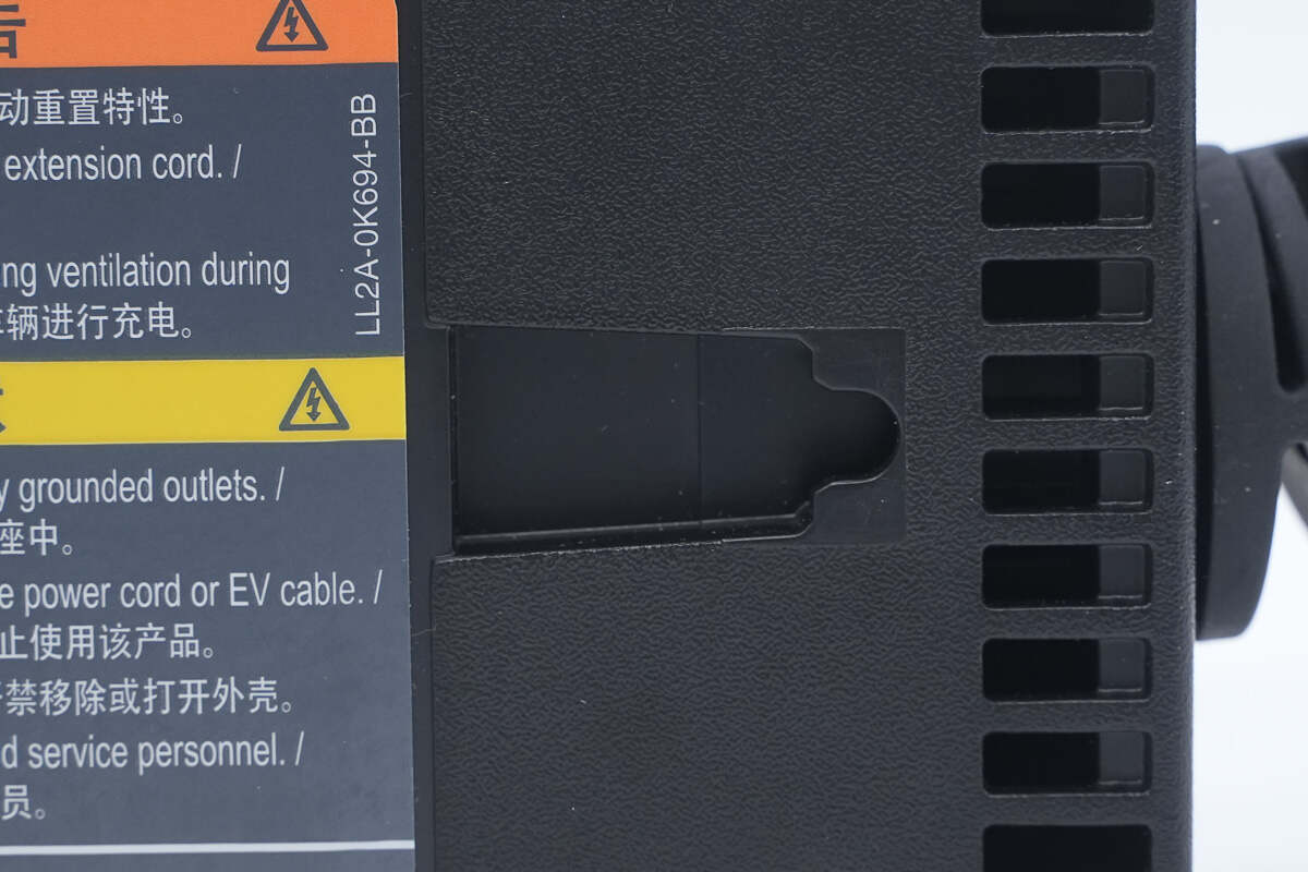
It is designed with a hook hole for convenient use in certain specific scenarios.
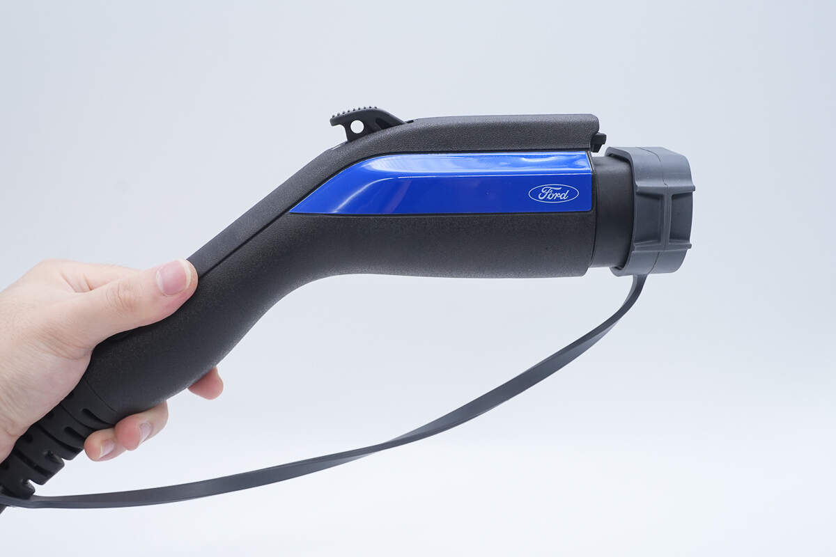
The charger is ergonomically designed.

Both sides also feature blue decorative panels with the Ford logo printed on them.

There is a release button on the top.

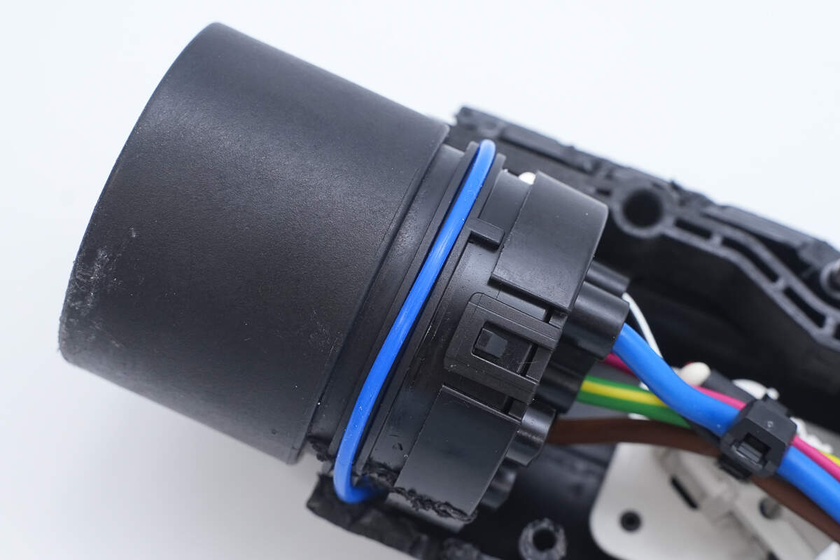
The end of the charging connector is sealed with a rubber sleeve to protect against dust, moisture, and oxidation.

It features a 7-pin AC charging connector, compatible with electric vehicle models from major automotive brands.
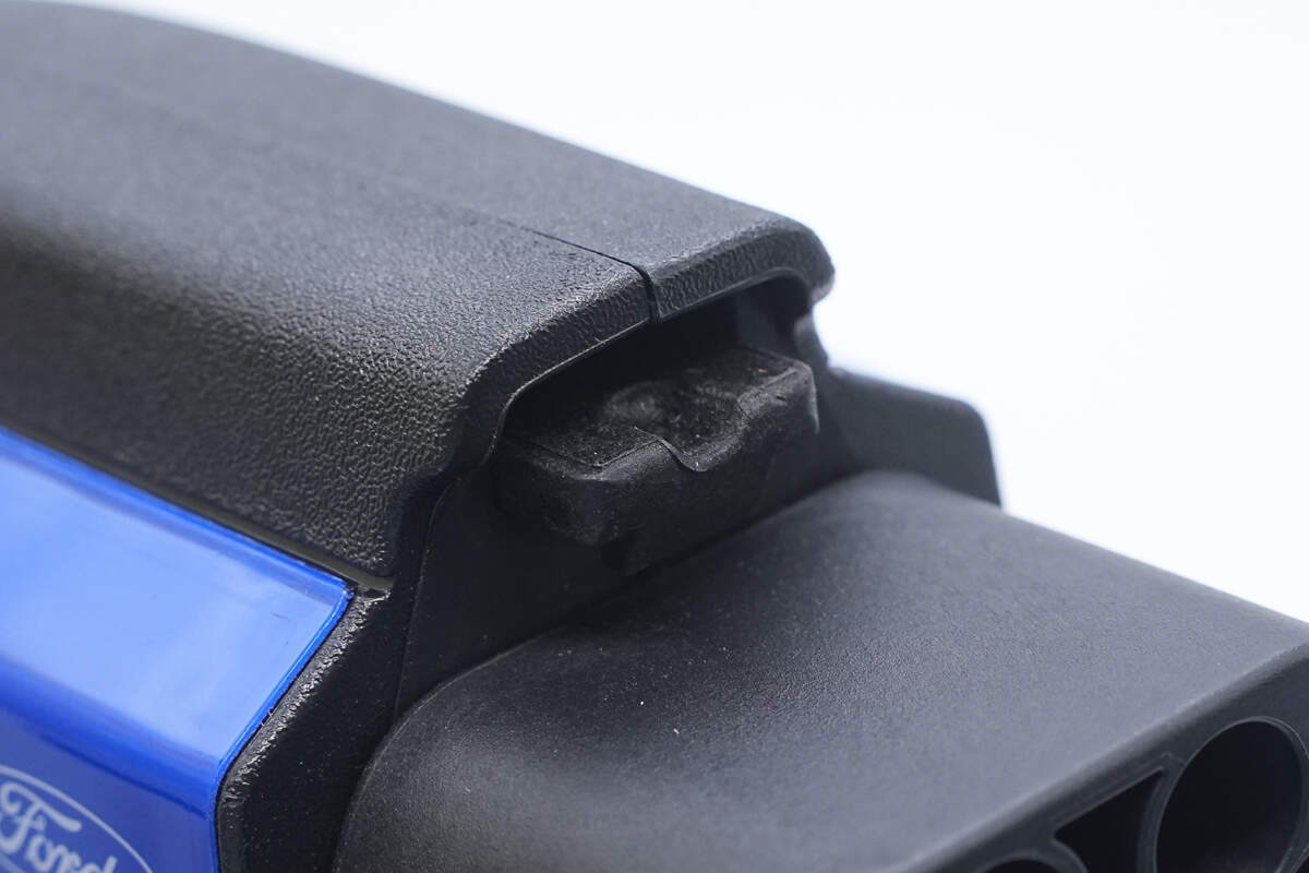
The latch is made of plastic.
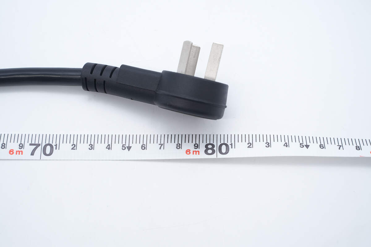
The total length of the Ford 1760W EV charger is about 6.8 meters.
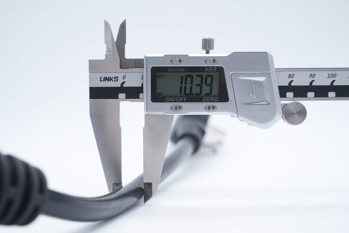
The cable diameter is about 10.39 mm (0.41 inches).
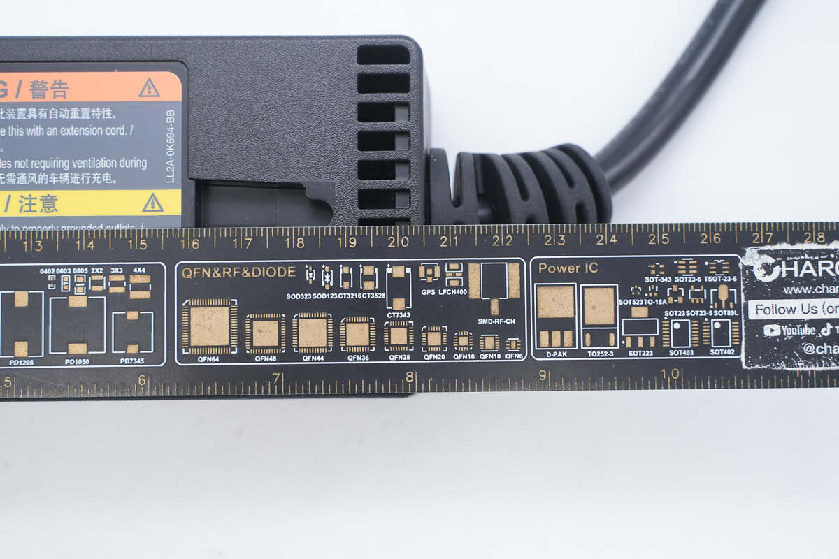
The length of the control box is about 20.5 cm (8.071 inches).
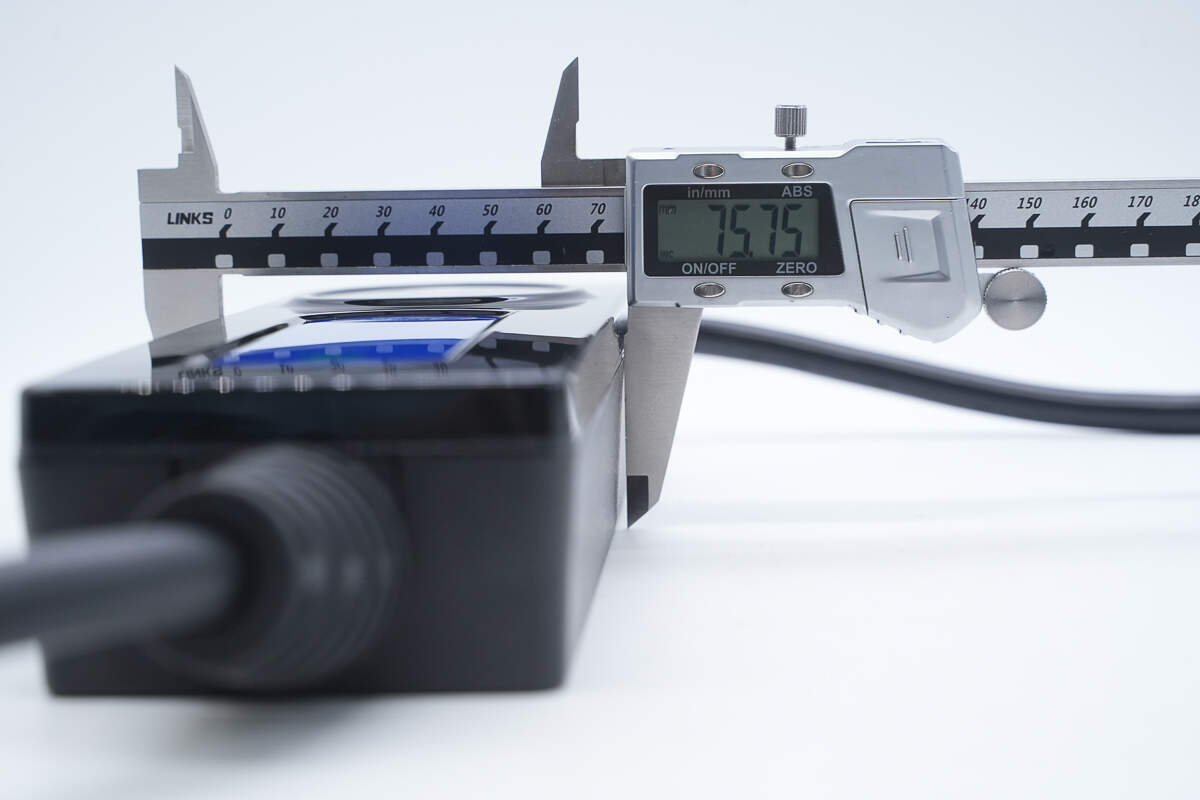
The width is about 75.75 mm (2.98 inches).
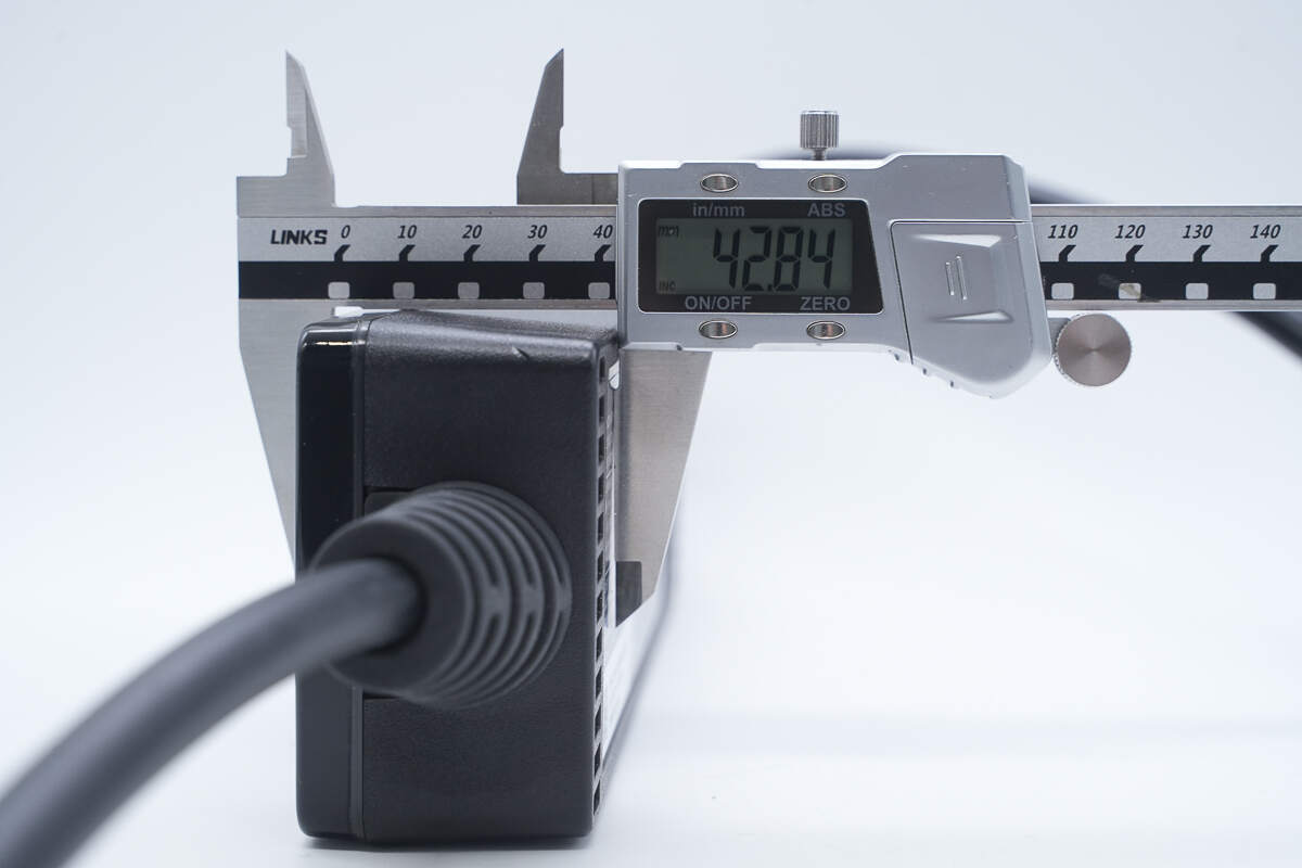
The thickness is about 42.84 mm (1.69 inches).

That's how big the control box is in the hand.
Because the weight was difficult to measure directly, a 4kg reference object was used to estimate that the charger weighs approximately 2kg.
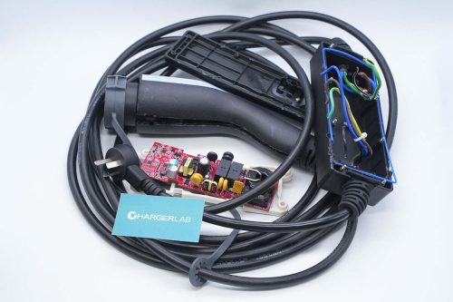
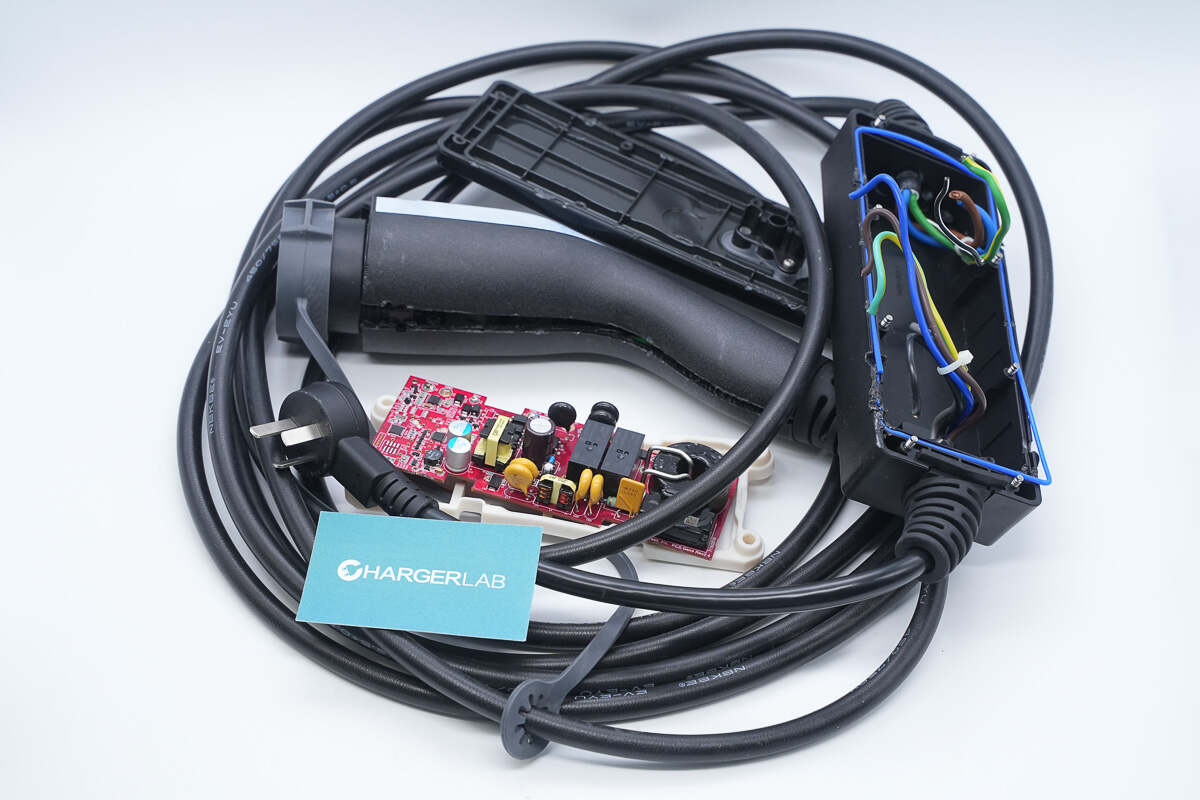
Teardown
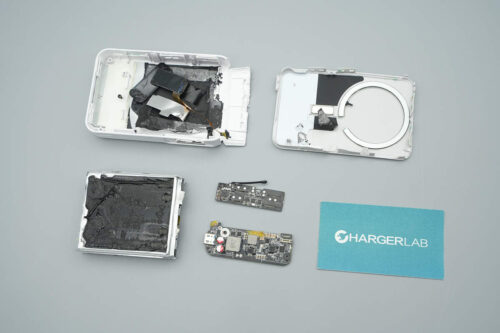
Next, let's take it apart to see its internal components and structure.
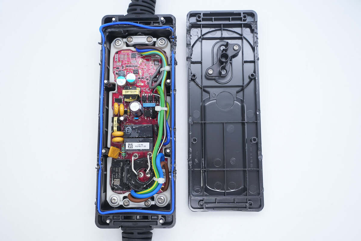
After opening the control box housing, a blue sealing ring can be seen inside.
The light guide plastic is secured with a black plastic plate and screws.
The edge of the PCB is enclosed in a white plastic housing, secured at all four corners with screws.
The cable is secured by a white plastic plate and screws, with the three wires bundled together with a cable tie.
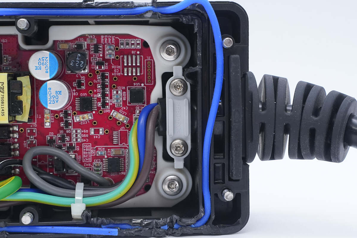
The other end of the cable features the same design.
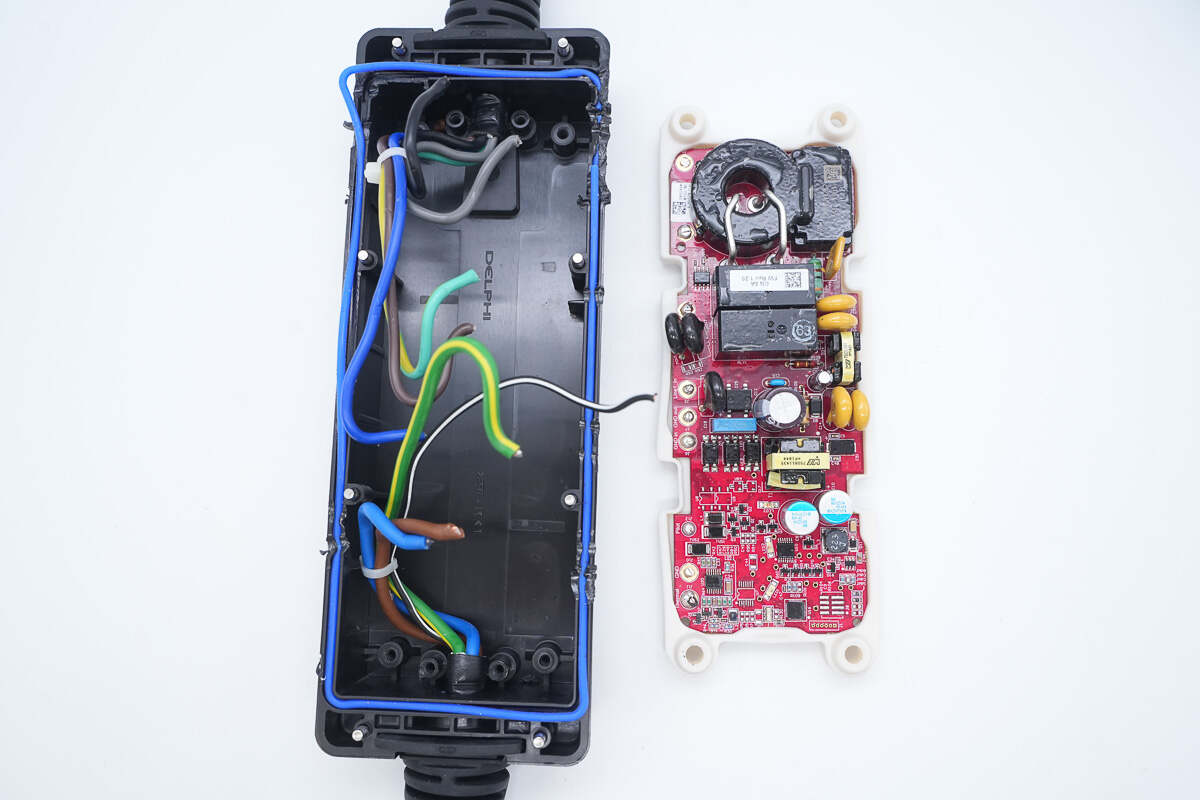
Remove the screws, cut the wires, and take out the PCB.
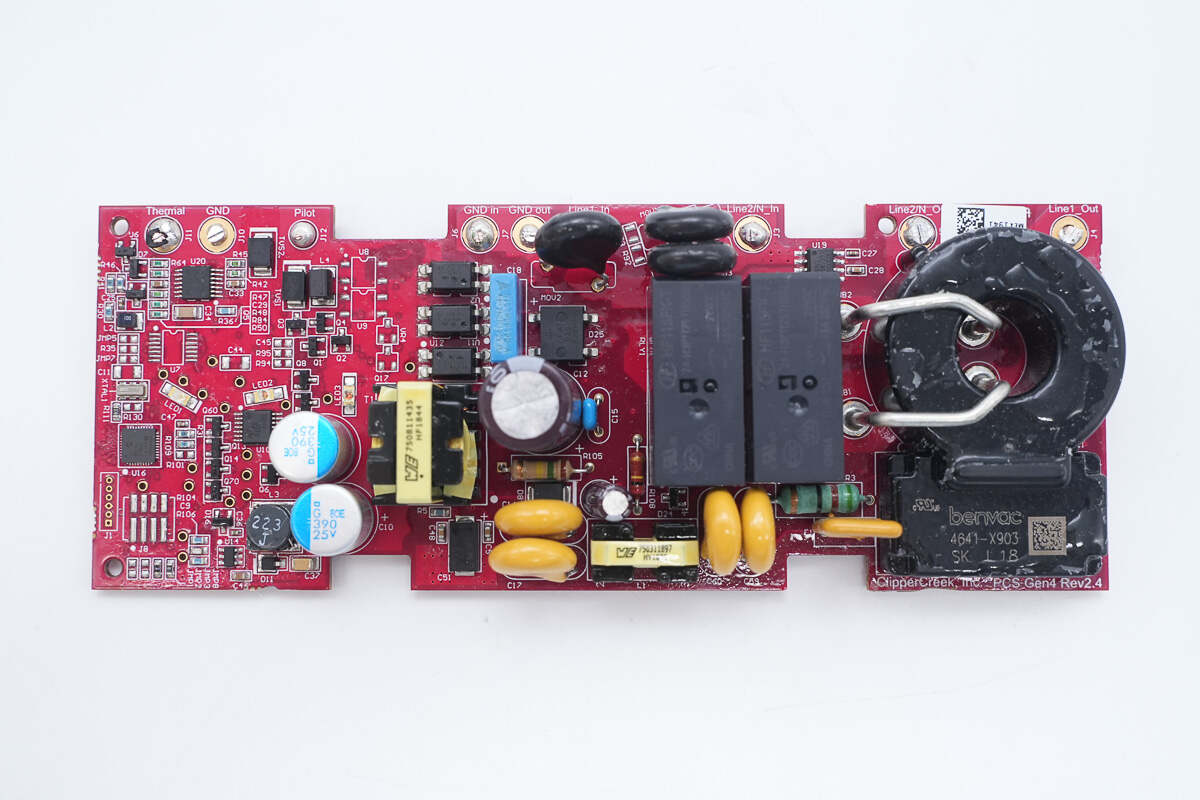
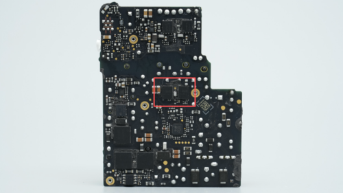
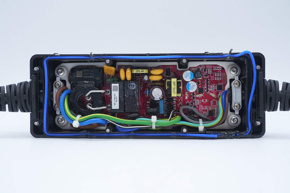
The front side of the PCB contains components such as the MCU, operational amplifier chip, buck converter chip, transformer, relay, current transformer, filter capacitors, and indicator lights.
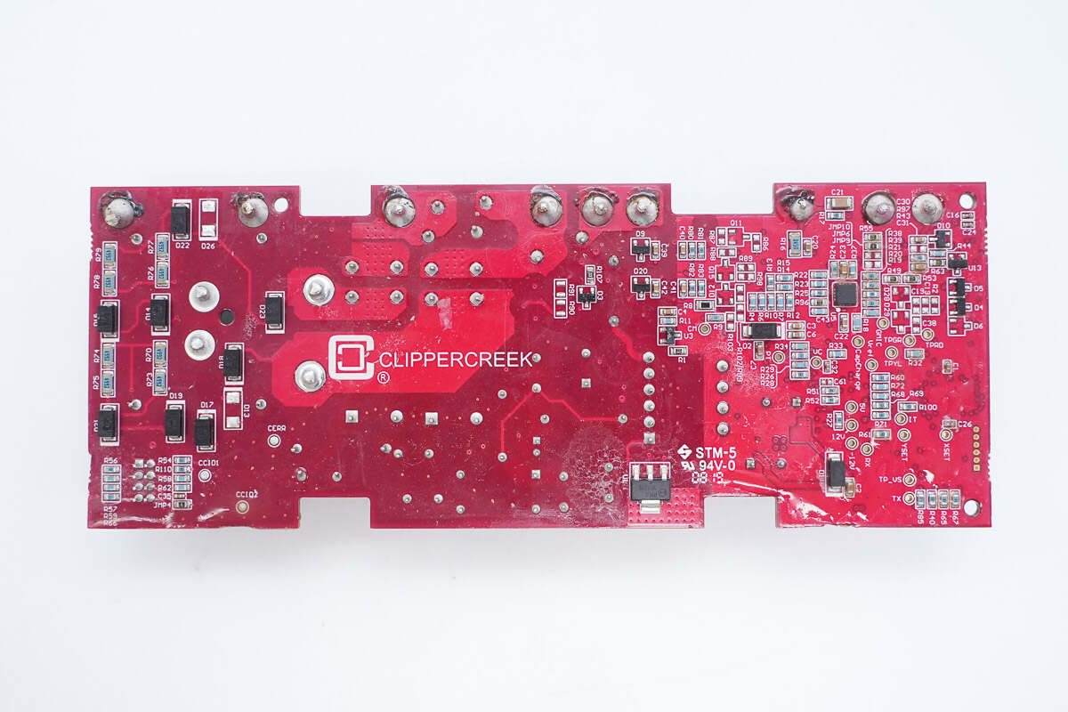
The back side contains multiple components such as a switching power supply chip, an operational amplifier chip, and output voltage sensing resistors.
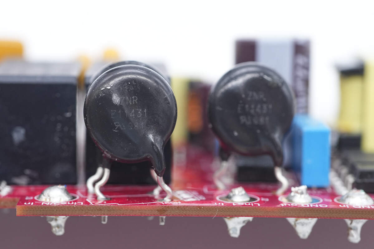
Varistors are placed at the AC input for surge protection.
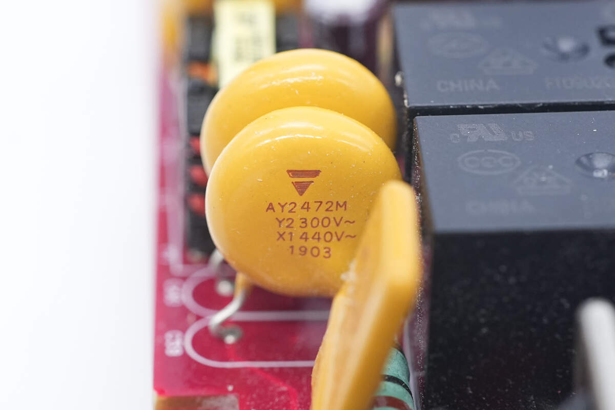
The yellow Y capacitors are from VISHAY.
The self-resetting fuse is used for overcurrent protection.
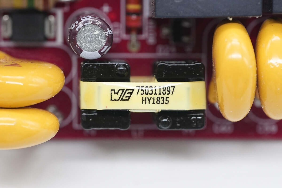
The filter inductor is from Würth.
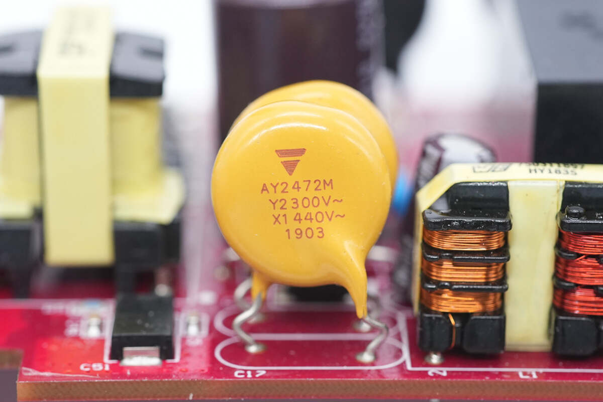
The yellow Y capacitors are from VISHAY.
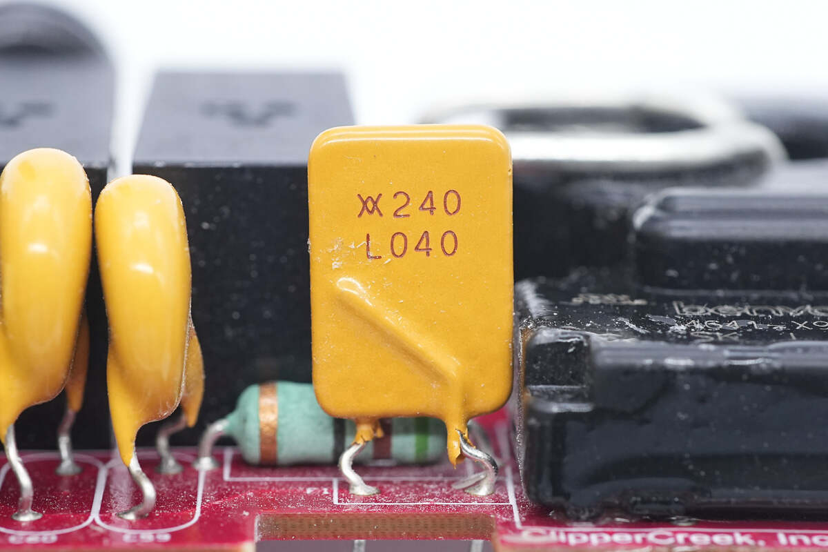
Close-up of the safety capacitor.
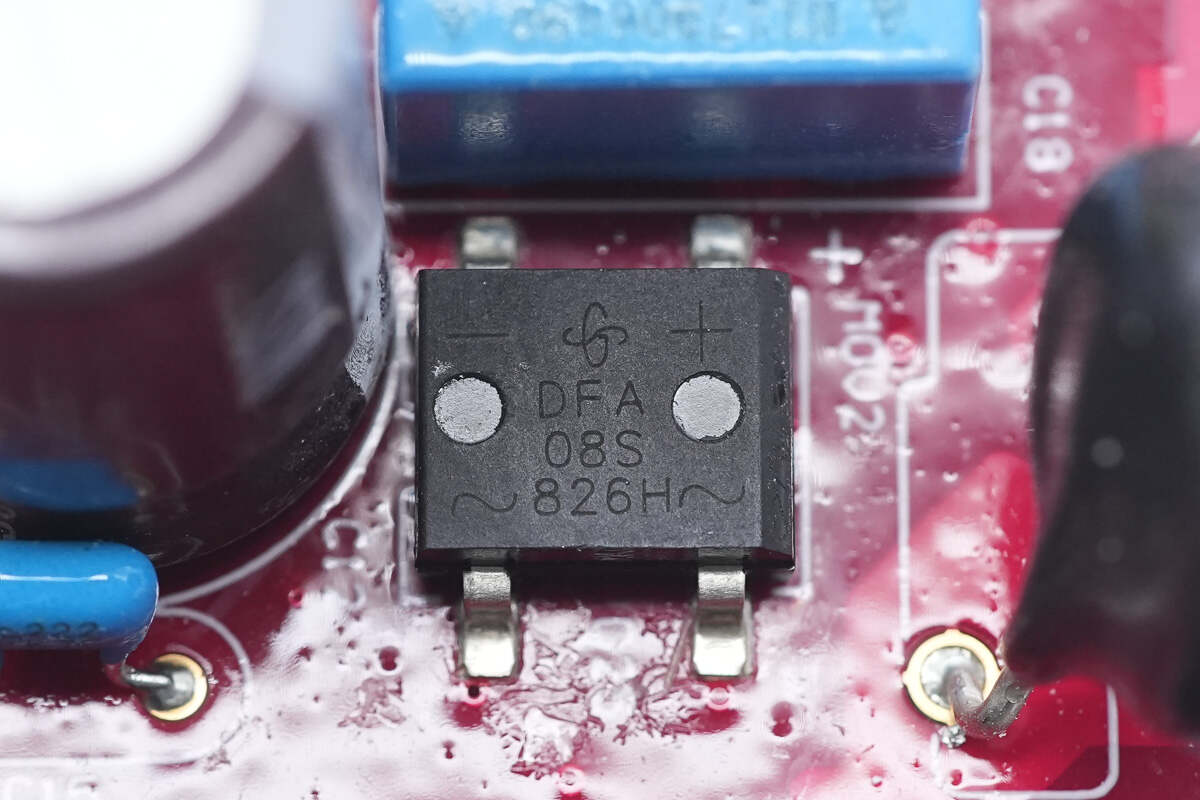
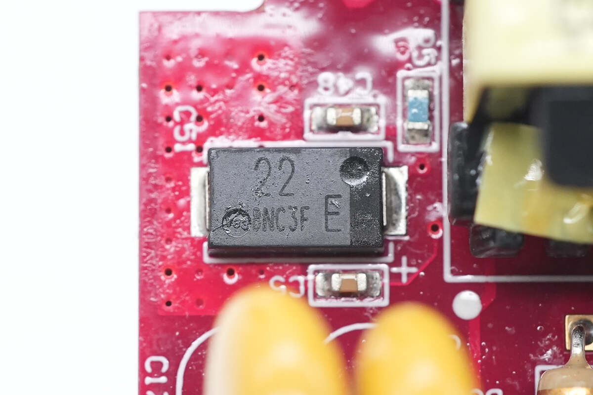
The bridge rectifier is from Vishay, model DFA08S, rated at 800V 1A.
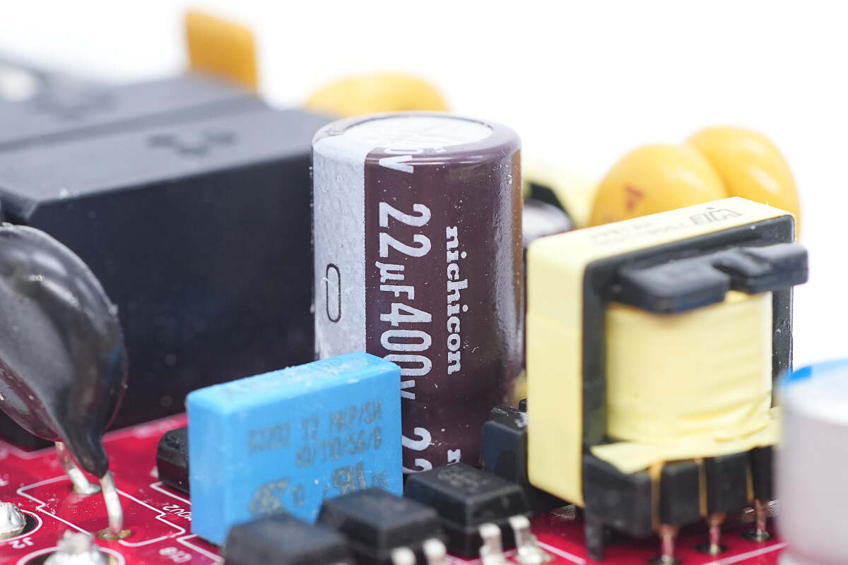
The high-voltage filter capacitor is from Nichicon, rated at 22μF 400V.
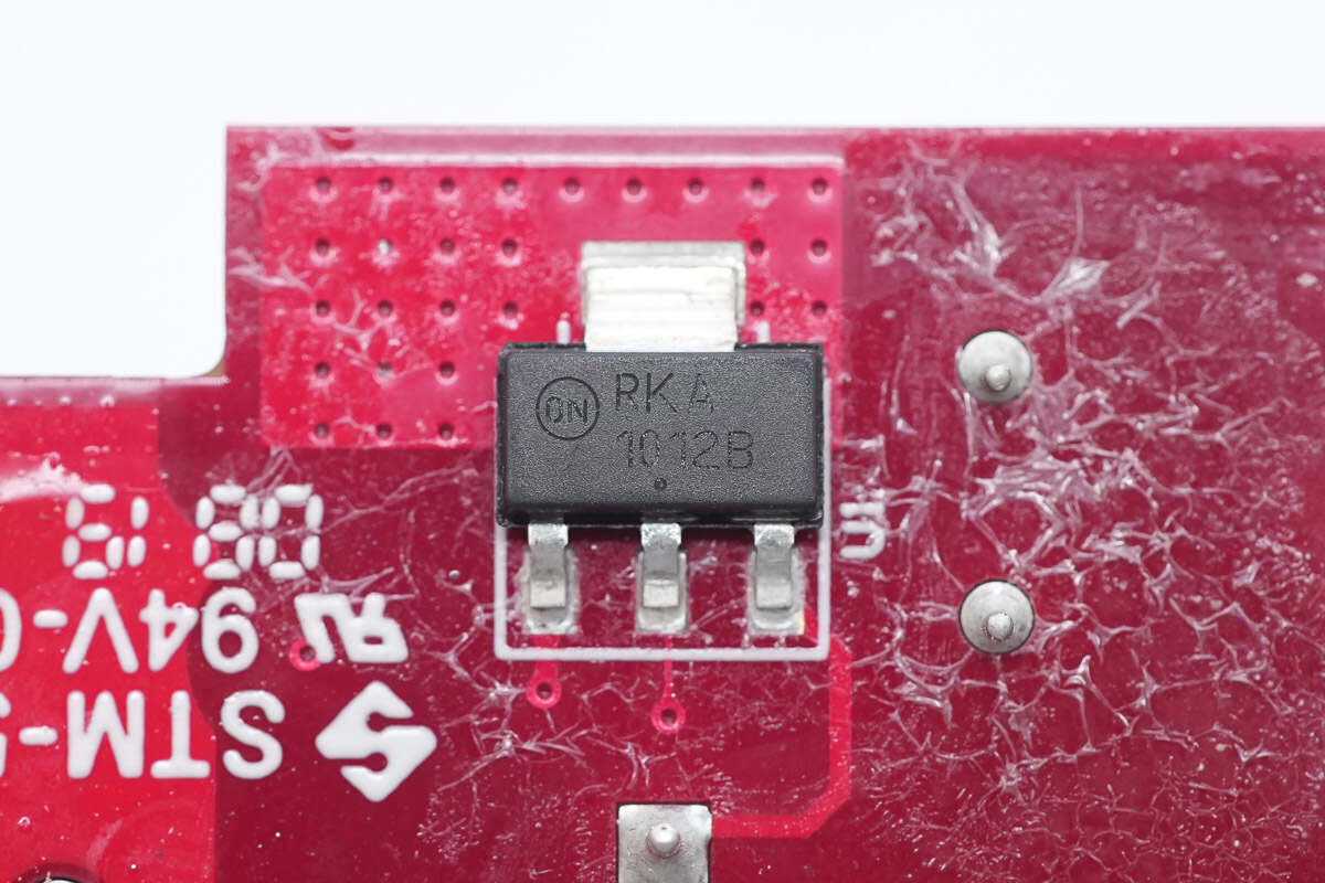
The switch-mode power supply (SMPS) chip is from Onsemi, model NCP1012B. It integrates a current-mode controller and a 700V power switch. The switching frequency is 100kHz. It supports self-supply without the need for an auxiliary winding and features comprehensive protection functions. The package type is SOT-223.
The tantalum capacitor, used for powering the master control chip, is from Panasonic and is rated at 22μF 25V.
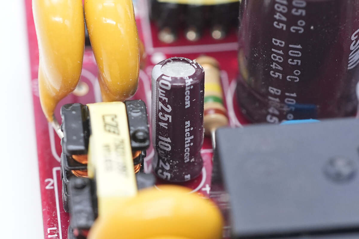
The power supply capacitor is from Nichicon, rated at 10μF 25V.
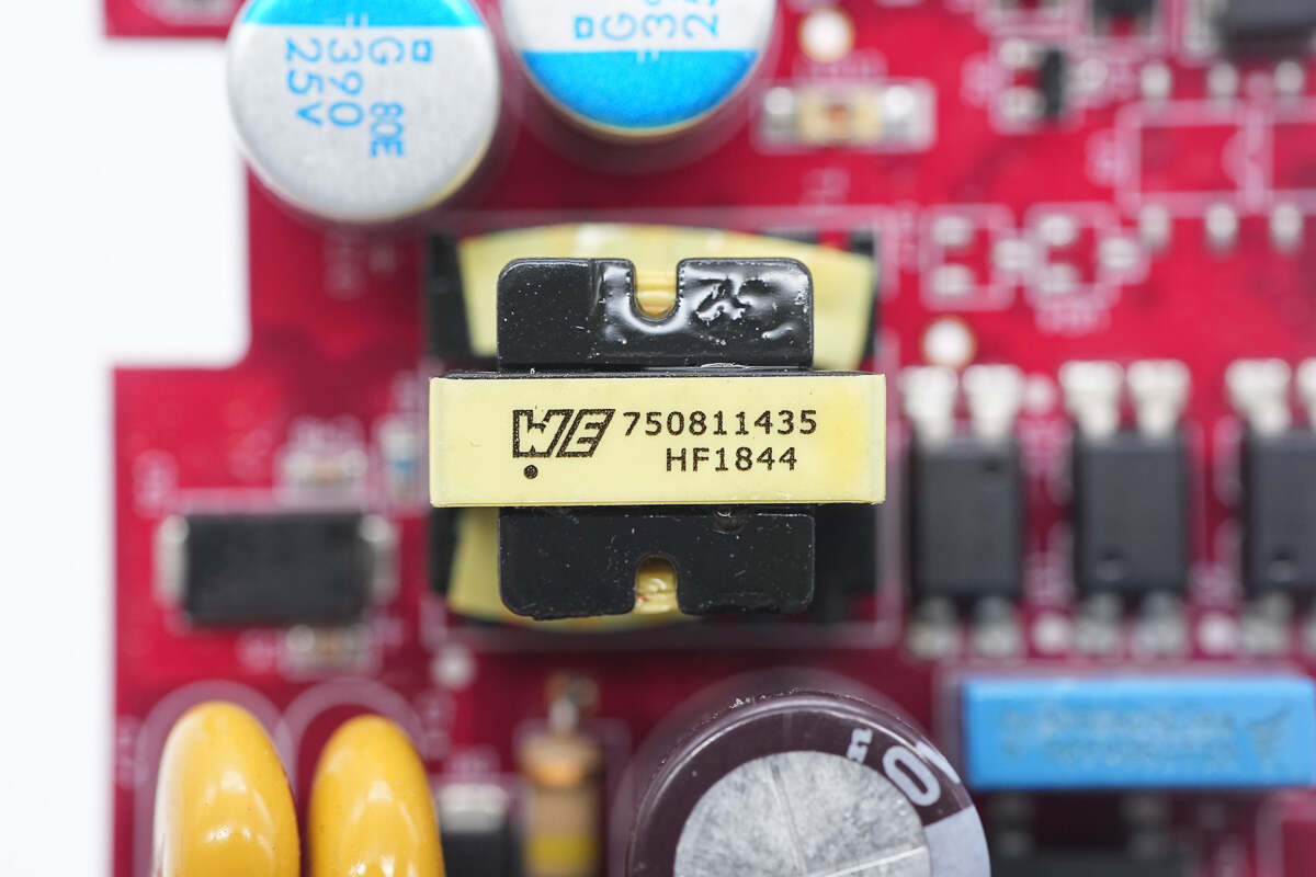
The transformer is from Würth.
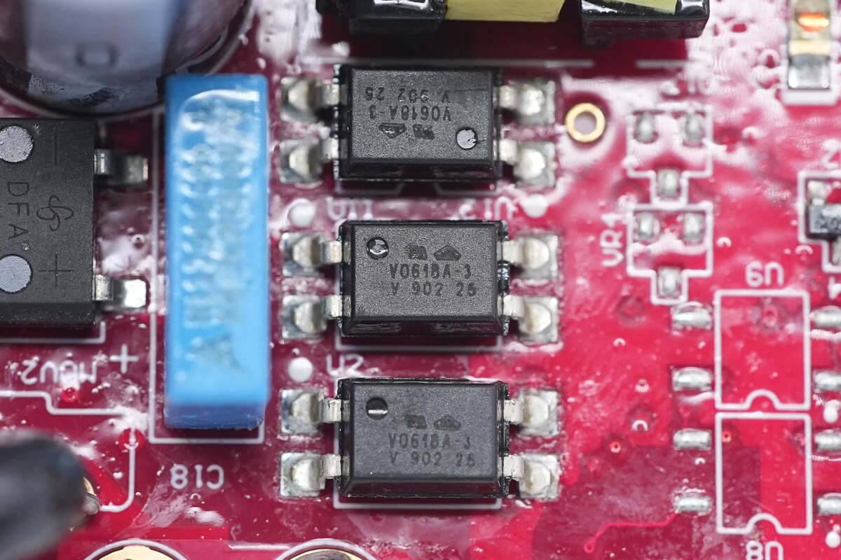
Three optocouplers are used for output voltage feedback and circuit protection.
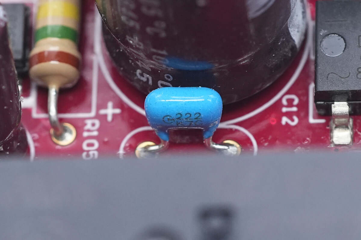
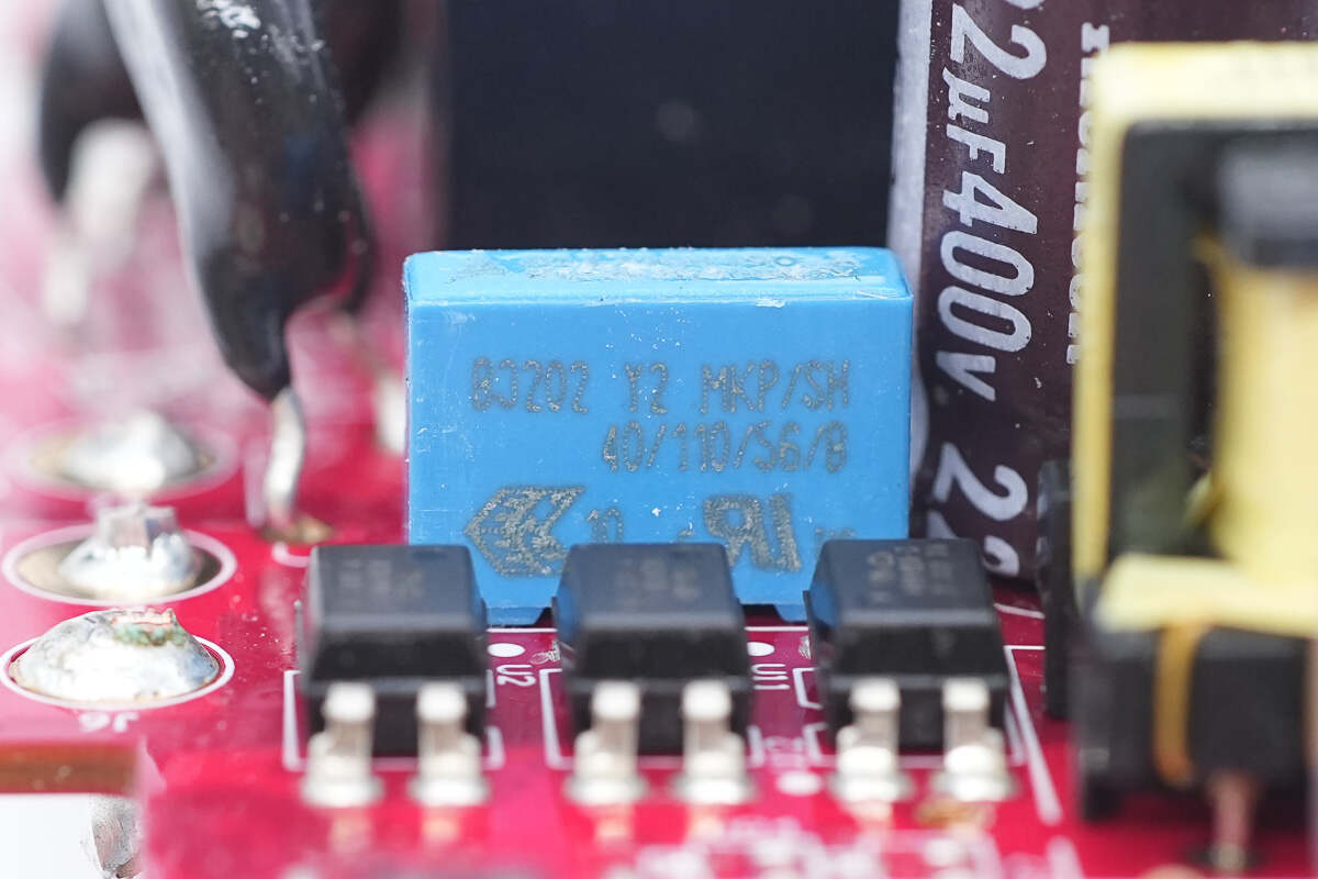
Close-up of the blue ceramic capacitor.
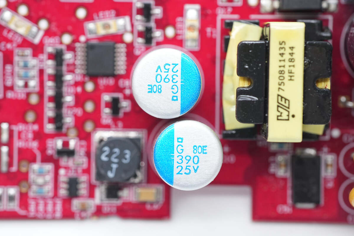
These two capacitors are from NCC, belonging to the PSG series of conductive polymer solid capacitors, rated at 390μF 25V.
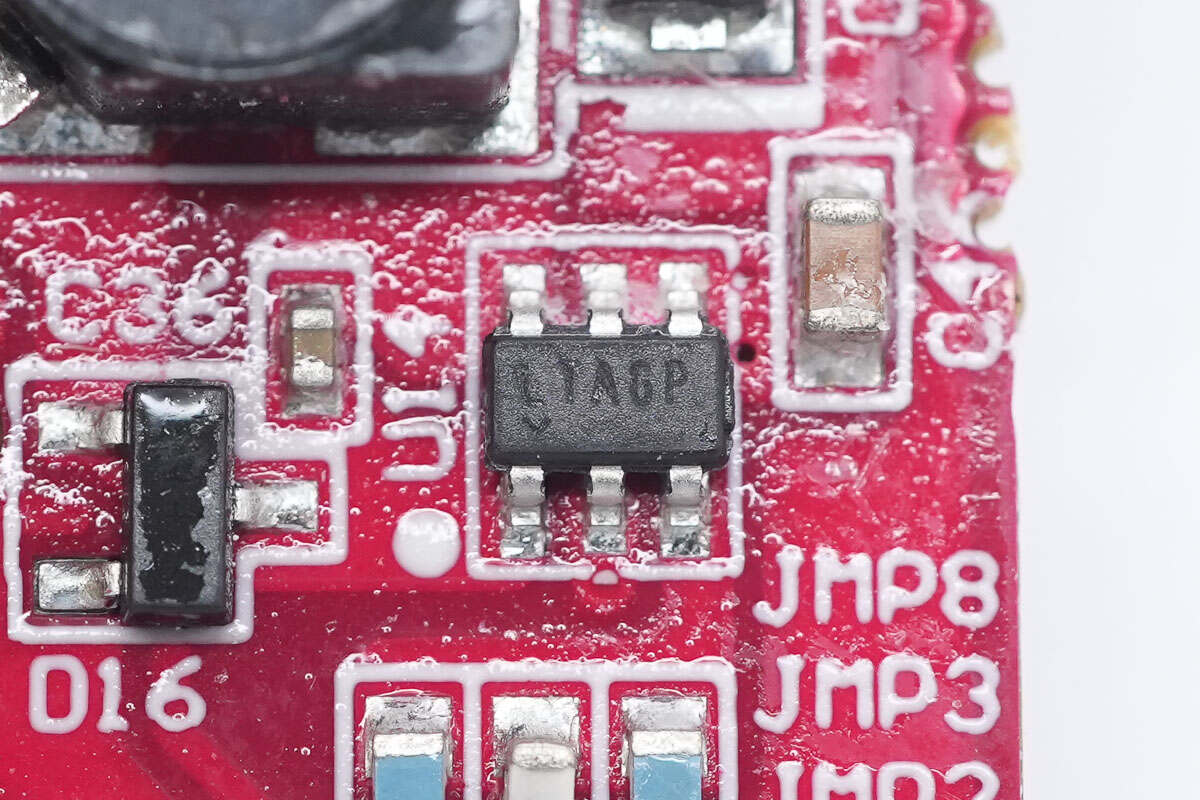
The buck converter chip is from ADI, marked with LTAGP, model LT1933. It supports a 36V input, 600mA output current, and operates at a switching frequency of 500kHz. The package type is SOT-23.
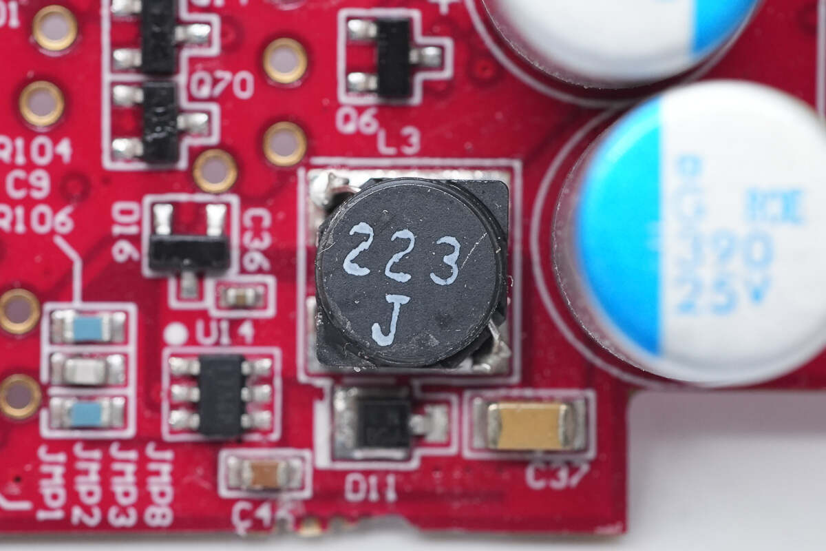
Close-up of the buck inductor.
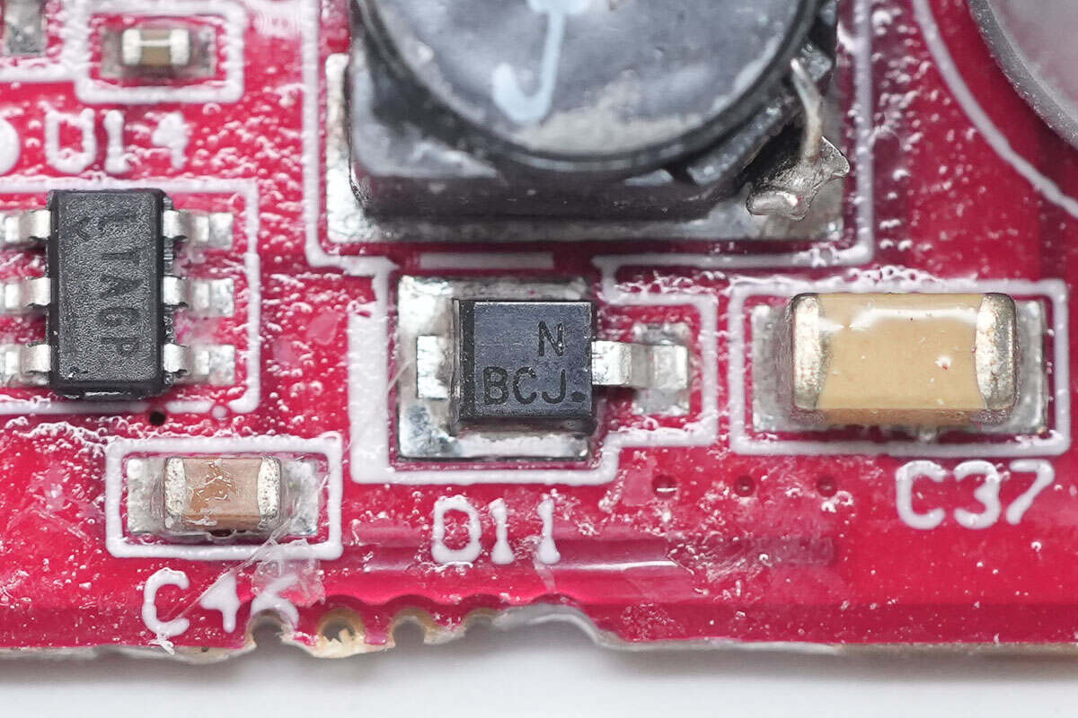
Close-up of the freewheeling diode.
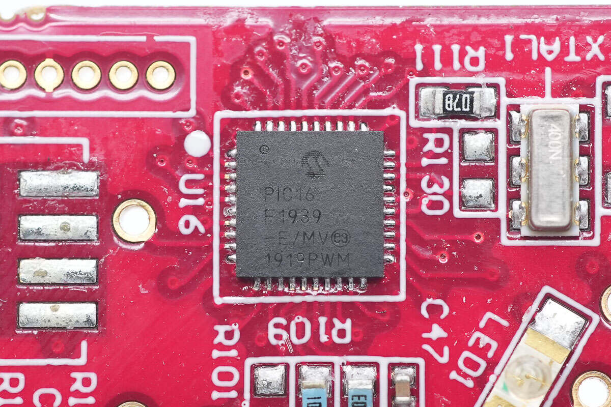
The MCU is from Microchip, model PIC16F1939. It is an 8-bit CMOS microcontroller with 40 pins, flash memory, and an integrated LCD driver.
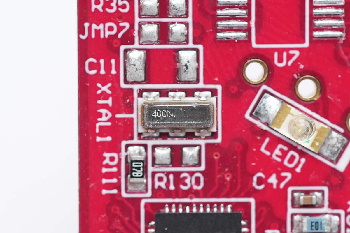
Close-up of the clock crystal oscillator.
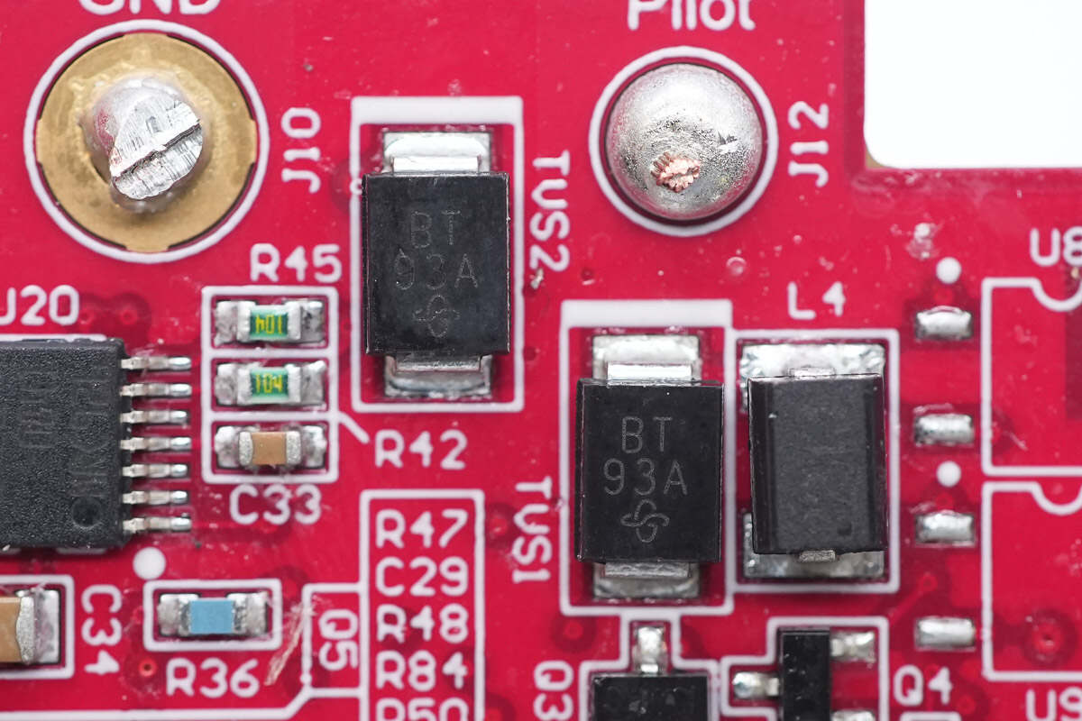
The VISHAY TVS diode is used for overvoltage protection.
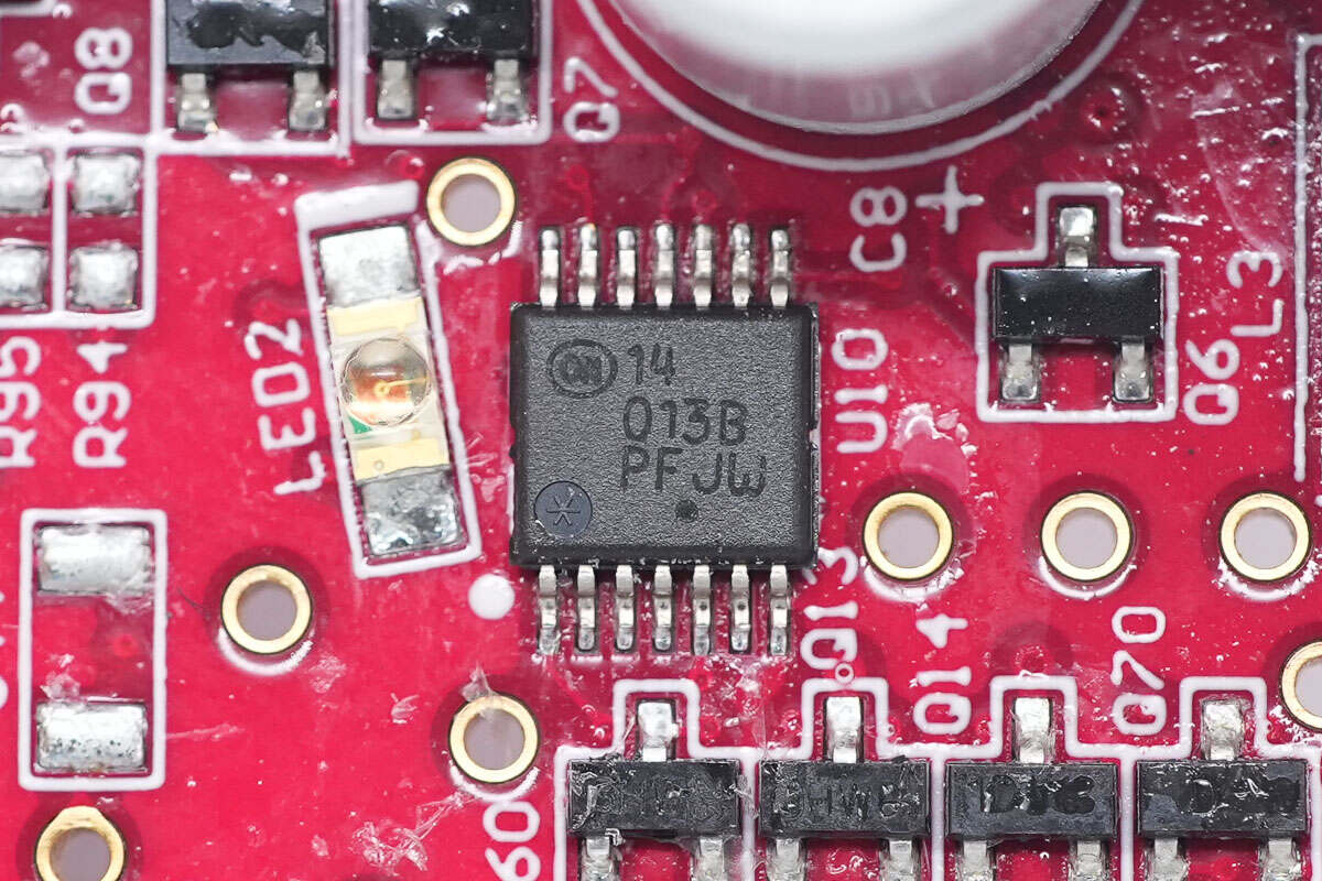
The Onsemi MC14013B dual D-type flip-flop features a monolithic structure with MOS P-channel and N-channel enhancement devices. Each flip-flop is equipped with independent data input (D), direct set (S), direct reset (R), clock input (C), and complementary outputs (Q and Q̅).
This device can be used as a shift register unit or configured as a T-type flip-flop, making it suitable for applications such as counters and signal switching. Its CMOS-based design offers low power consumption and high reliability, meeting the requirements of logic control and timing circuit designs.
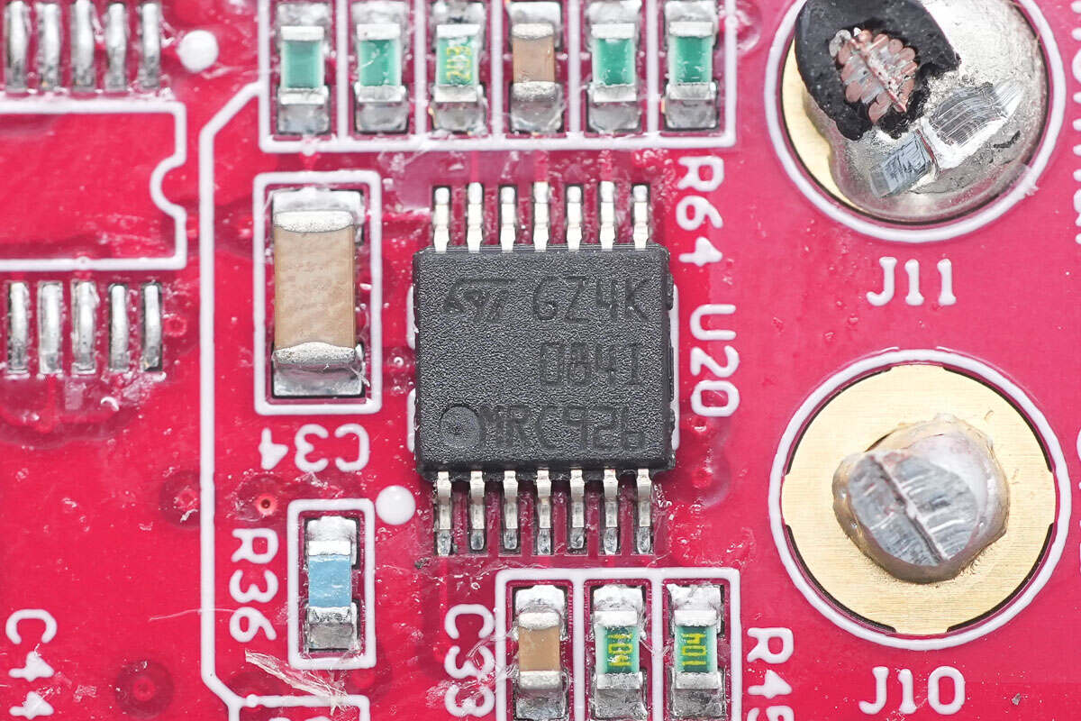
The operational amplifier chip is from STMicro, model TL084I. It is a general-purpose JFET-input quad op-amp, packaged in TSSOP14.
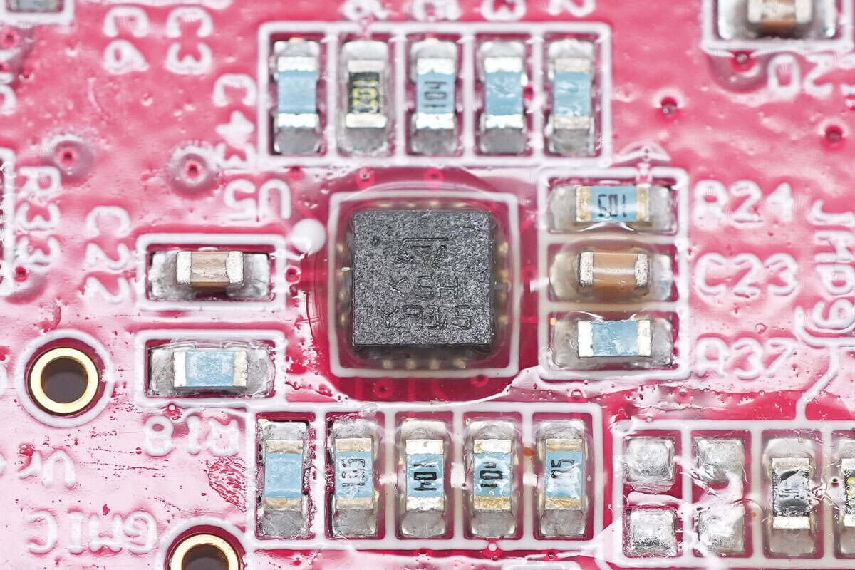
The operational amplifier chip is from STMicro, marked with K5H, model LM2902Q4T. It is a low-power quad op-amp, packaged in QFN16.
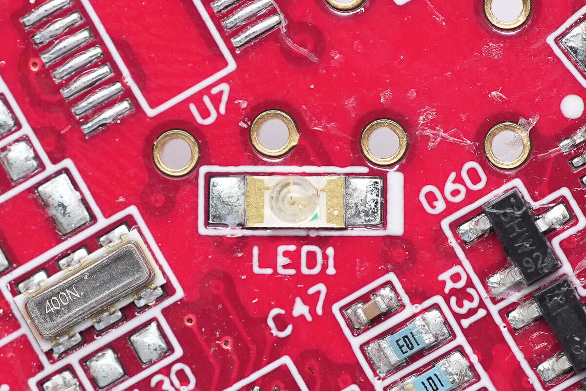
Close-up of the power indicator LED.
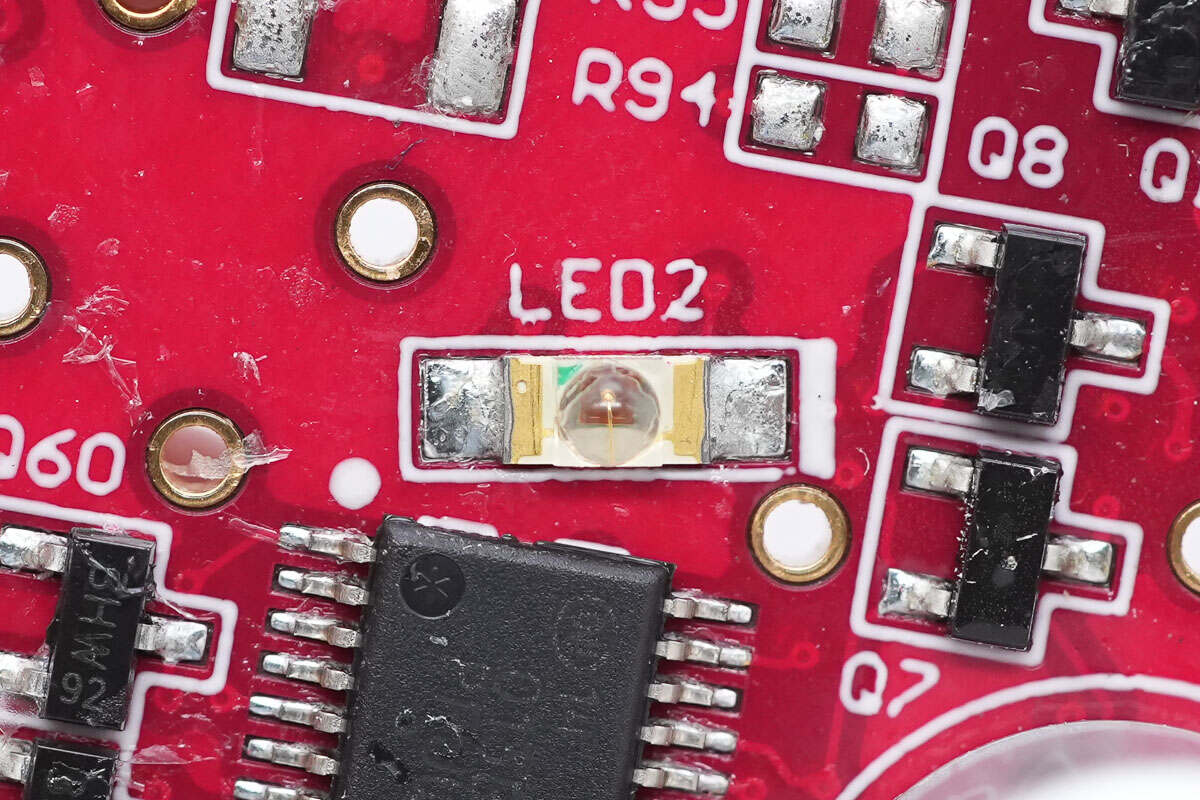
Close-up of the fault indicator LED.
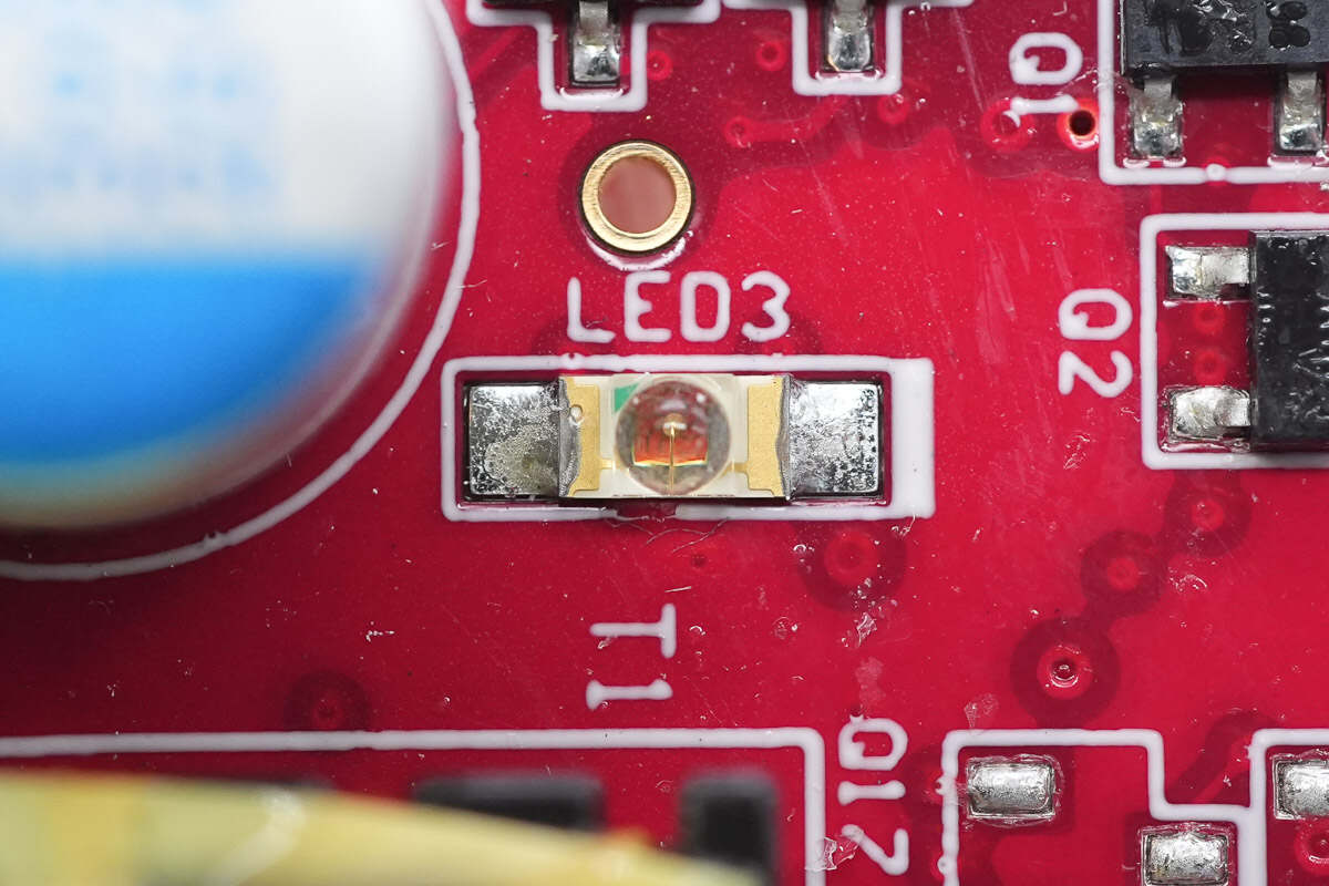
Close-up of the power socket indicator light.
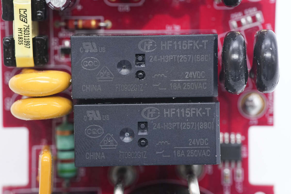
The two power relays are from HONGFA, model HF115FK-T, with a contact rating of 16A 250V and a coil voltage of 24V. They are used for charging output control.
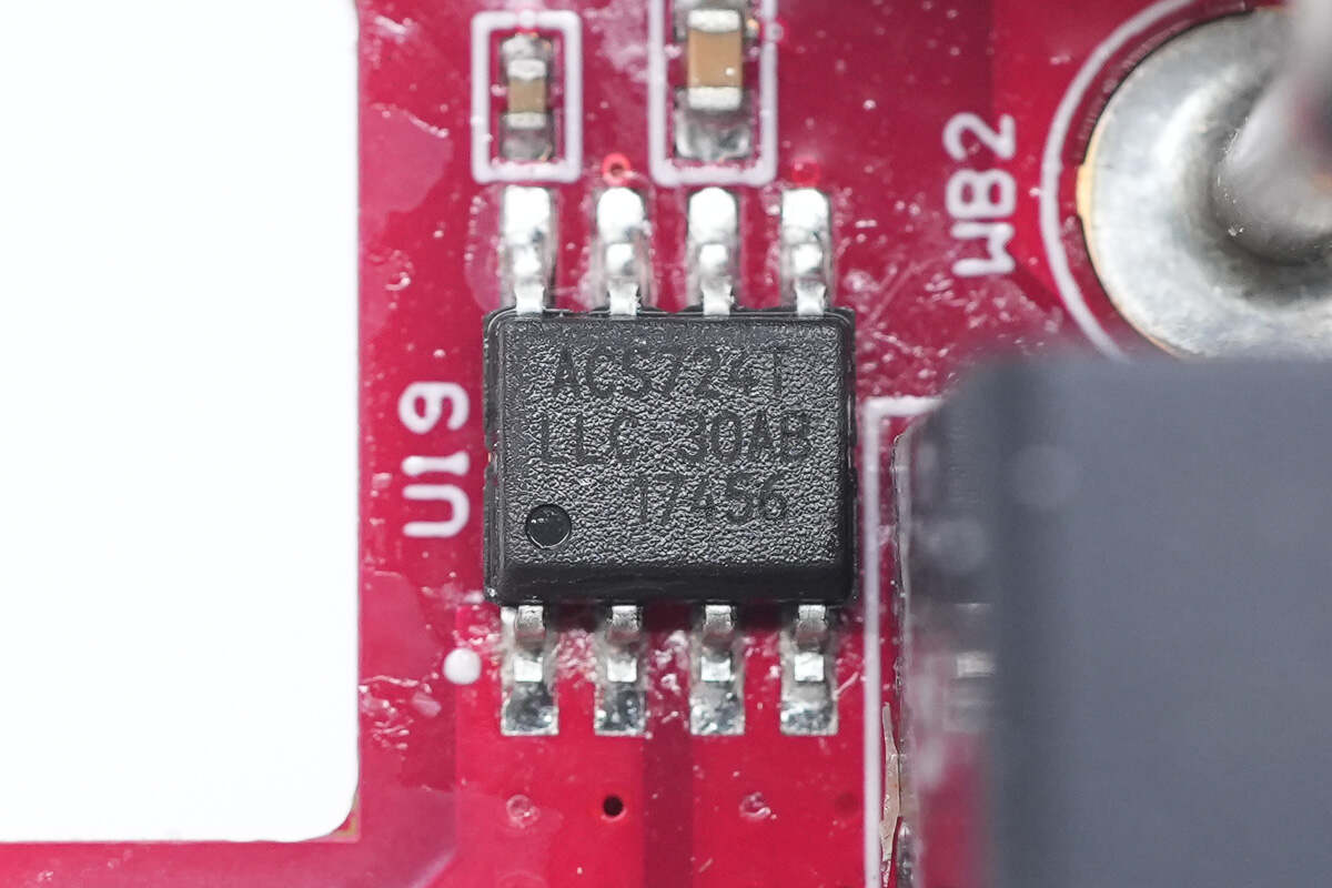
The Hall current sensor chip is from ALLERGO, model ACS724TLLCTR-30AB-T. It is an automotive-grade isolated current sensing chip with a 30A range, packaged in SOIC8.
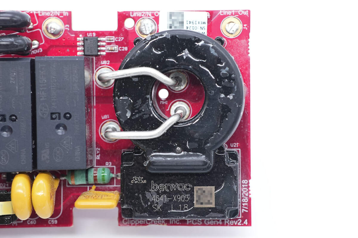
The zero-sequence current transformer is used for leakage current detection and provides leakage protection during the charging process.
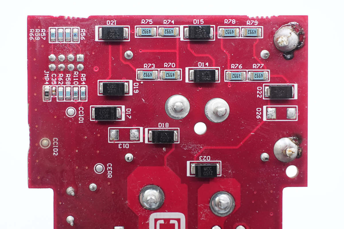
Close-up of the output voltage sensing resistors.
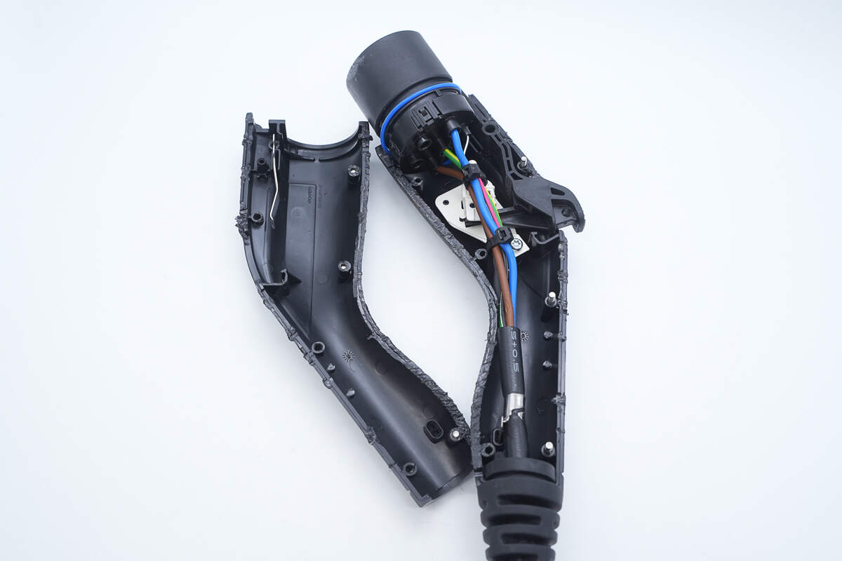
Cut open the charger casing.
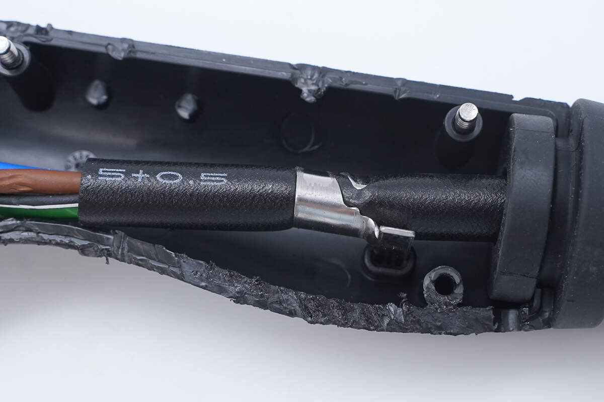
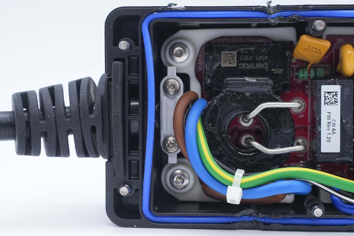
There is a metal ferrule on the wire for positioning, preventing the cable from being pulled out.
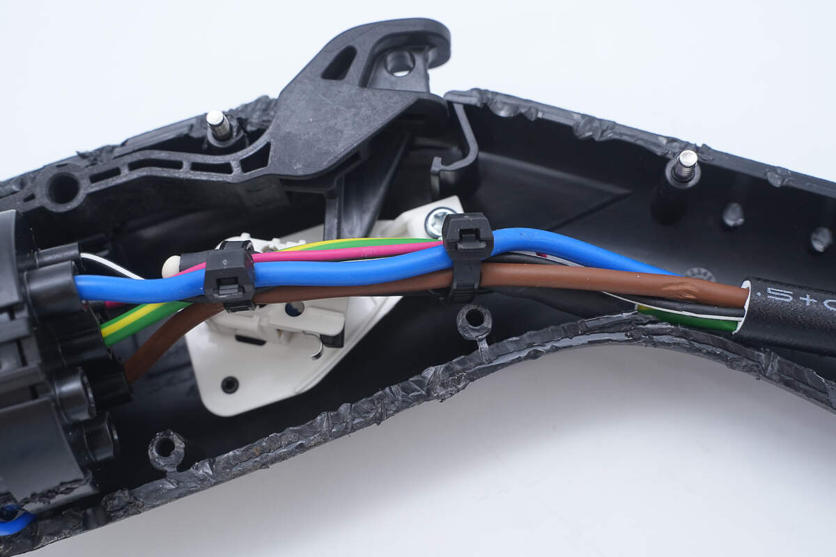
The wires are bundled using cable ties.
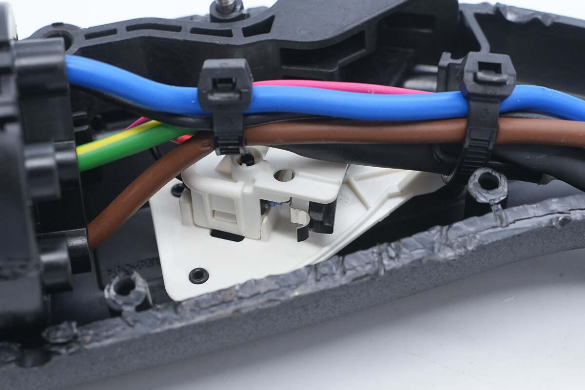
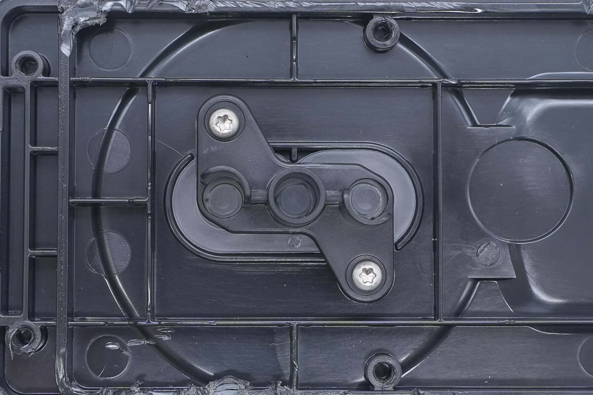
Below the wire, there is a micro switch used to detect whether the charger is properly connected.
It is equipped with a blue sealing gasket.
Well, those are all components of the Ford 1760W Portable EV Charger.
Summary of ChargerLAB
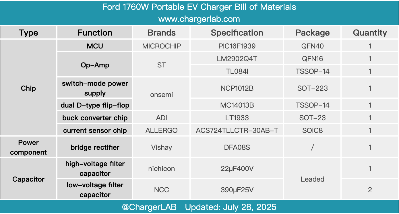
Here is the component list of the Ford 1760W Portable EV Charger for your convenience.
It supports an 8A charging current with a charging power of 1760W. The control box has three indicator lights that provide feedback on power status, faults, and power socket inspection. The total length reaches 6.8 meters, making it suitable for a wide range of applications and easy to use.
After taking it apart, we found that the PCBA module is secured with screws, and the wires are soldered. Inside the control box, a Microchip MCU is used for parameter acquisition and protection control, paired with operational amplifiers from STMicro. The switch-mode power supply chip is from Onsemi. A current transformer is employed for leakage current detection to provide leakage protection during charging, and the relays used to control charging are from HONGFA. The PCBA module is coated with conformal coating, and the components and reliable workmanship.
Related Articles:
1. Teardown of Enphase IQ8P 480W Microinverter (IQ8P-72-2-INT)
2. Teardown of Xiaomi 33W 5000mAh 3-in-1 Power Bank (NPB0533)
3. Teardown of 90W GaN Charger for Xiaomi 15 Pro (MDY-14-EC)