Introduction
In this issue, we bring you a teardown of Delta’s 300W power adapter, model ADP-300EB B. It comes with two built-in USB-C cables, both supporting 140W PD 3.1, along with a USB-C port that supports 100W PD. The adapter can deliver a total maximum output power of 300W. Now, let’s take a detailed look at the build quality and internal components of this Delta adapter.
Product Appearance
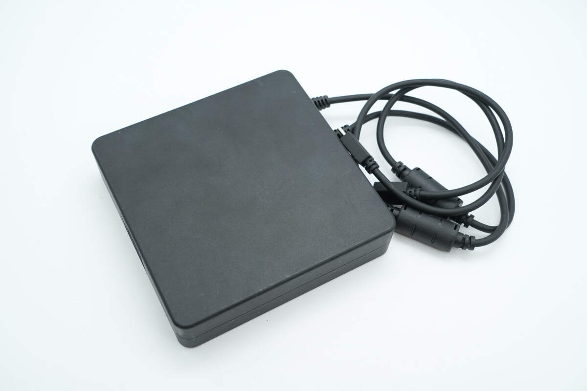
It features a flat, square-shaped design with a matte, fingerprint-resistant surface. The input cable is detachable, while the output side comes with two built-in USB-C cables.
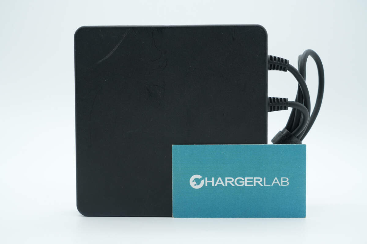
The design style is minimalist.
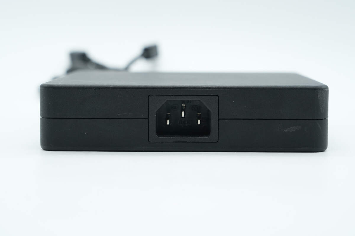
The input interface is a C7 connector.
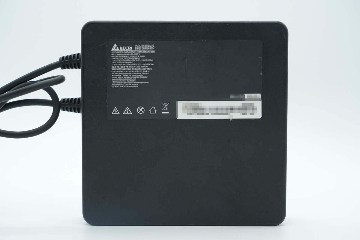
The bottom is labeled with the product nameplate.
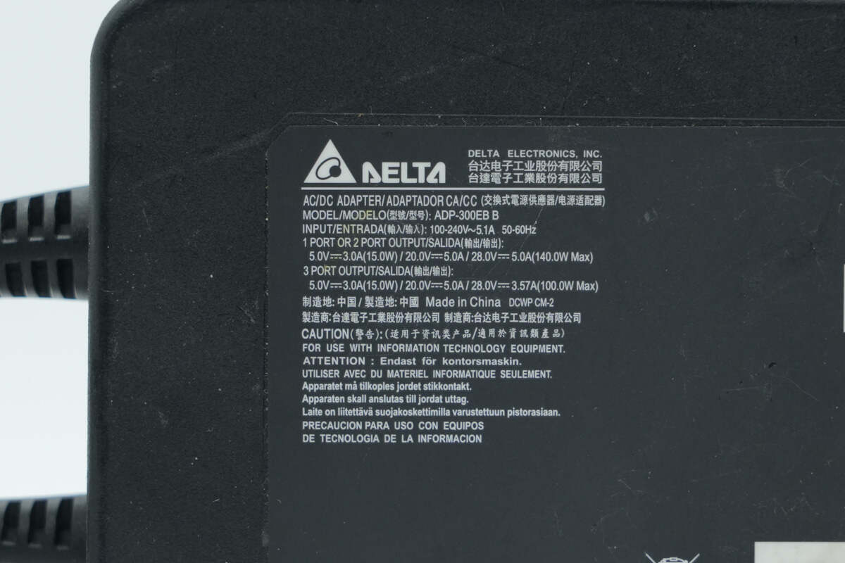
Model: ADP-300EB B
Input: 100-240V\~ 50/60Hz 5.1A
1/2 port output: 5V 3A, 20V 5A, 28V 5A (140W Max)
3 port output: 5V 3A, 20V 5A, 28V 3.57A (100W Max)
Manufacturer: Delta Electronics, Inc.
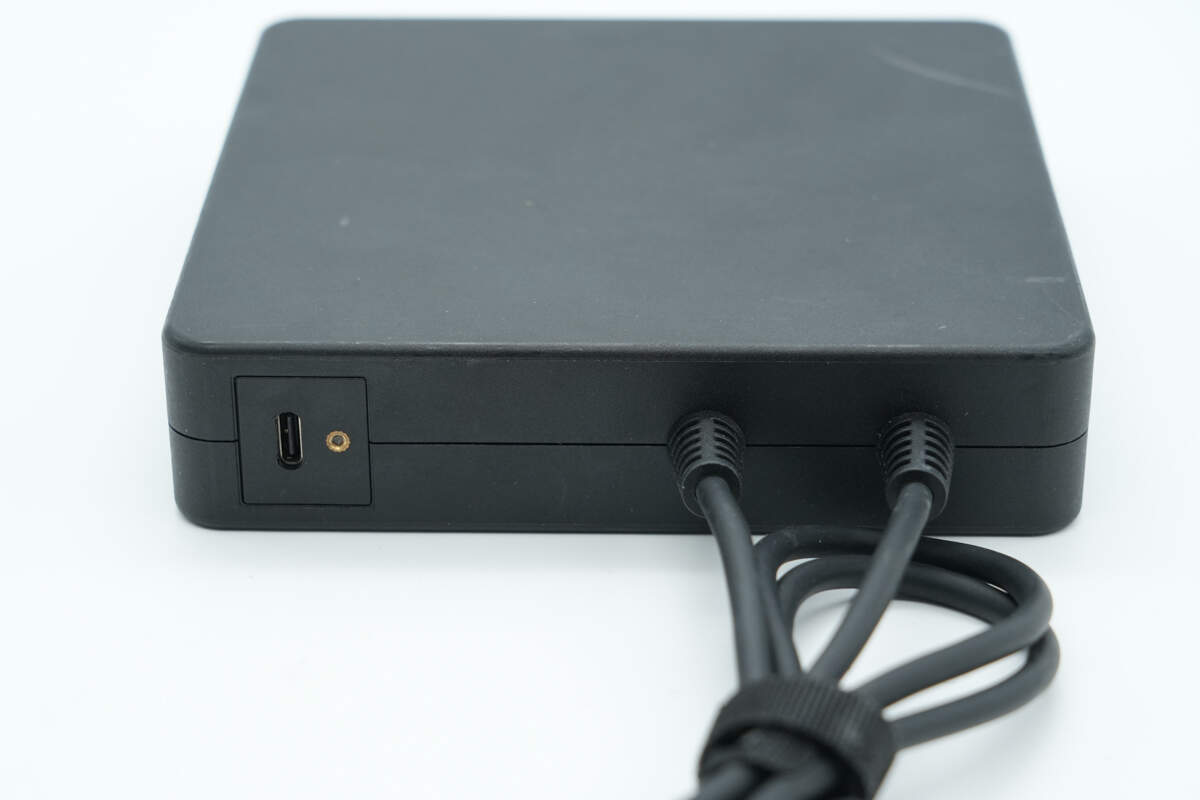
In addition to the two USB-C cables, the output side also has a USB-C port.
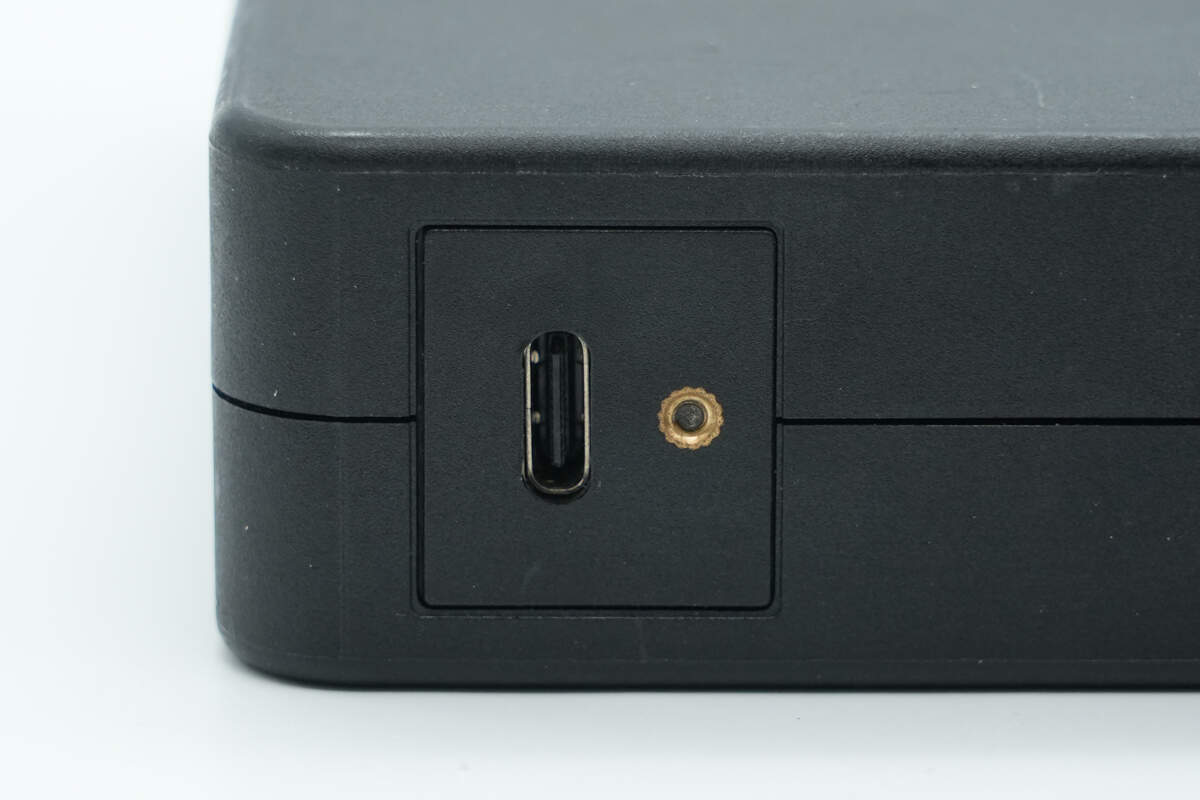
There is a mounting screw hole next to the USB-C port.
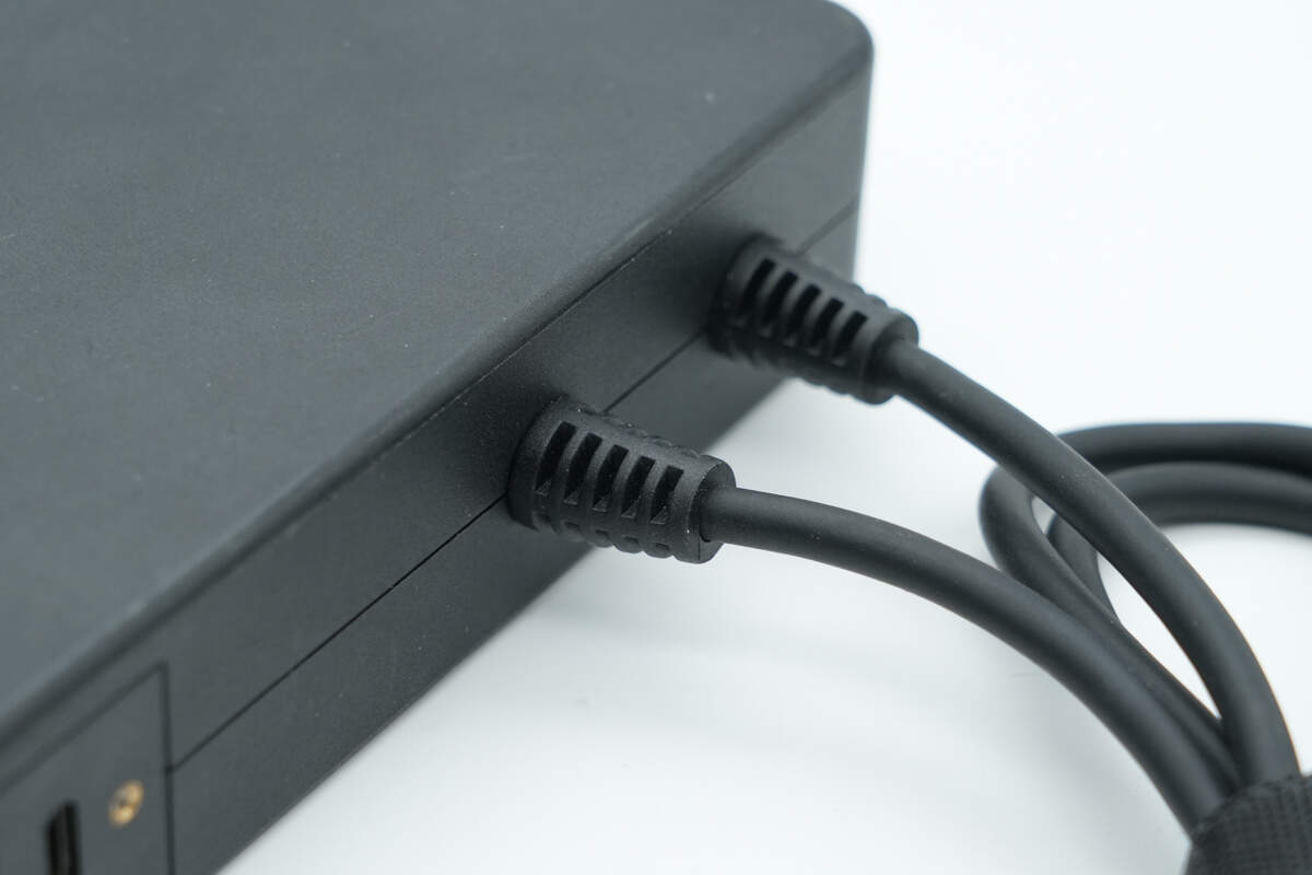
The two USB-C cables feature an anti-bending design.
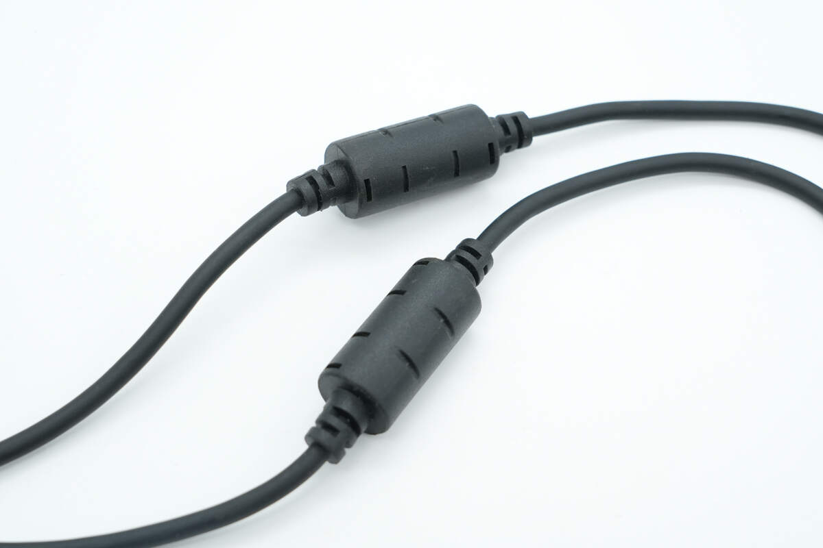
Both are equipped with anti-interference ferrite cores.
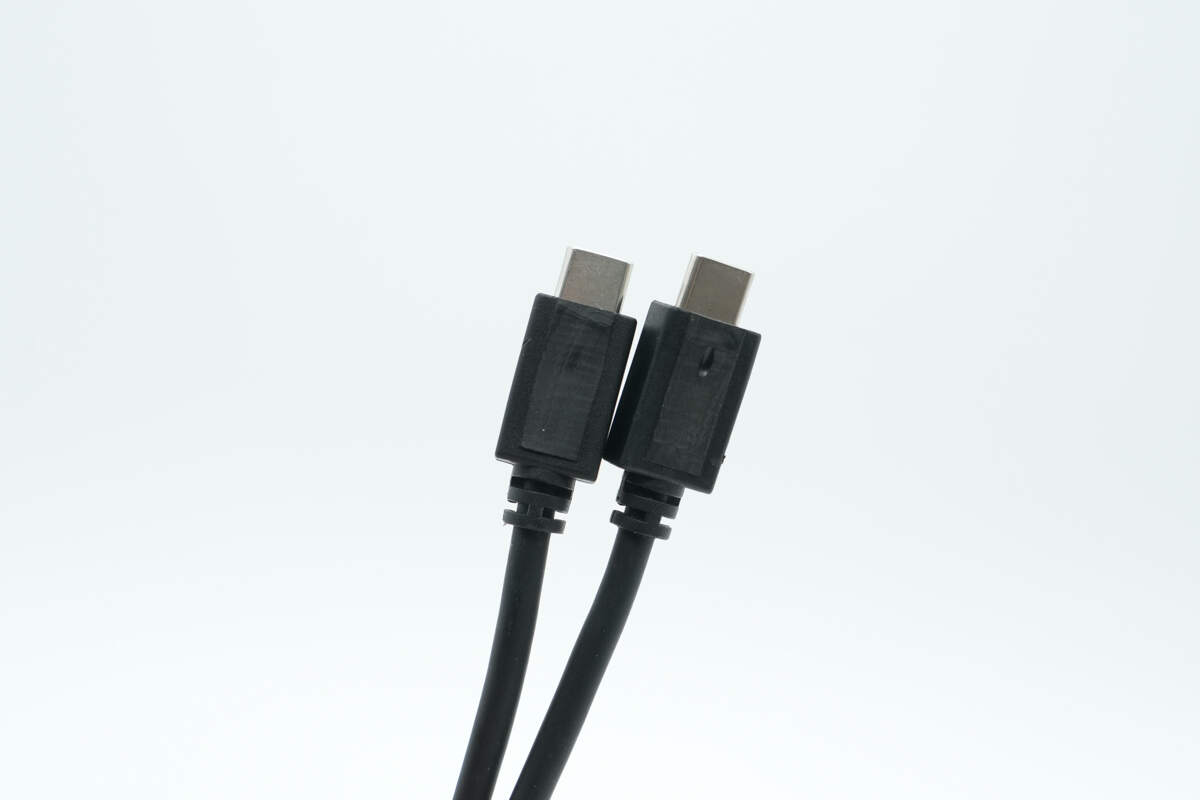
The connectors feature the matte surface finish.
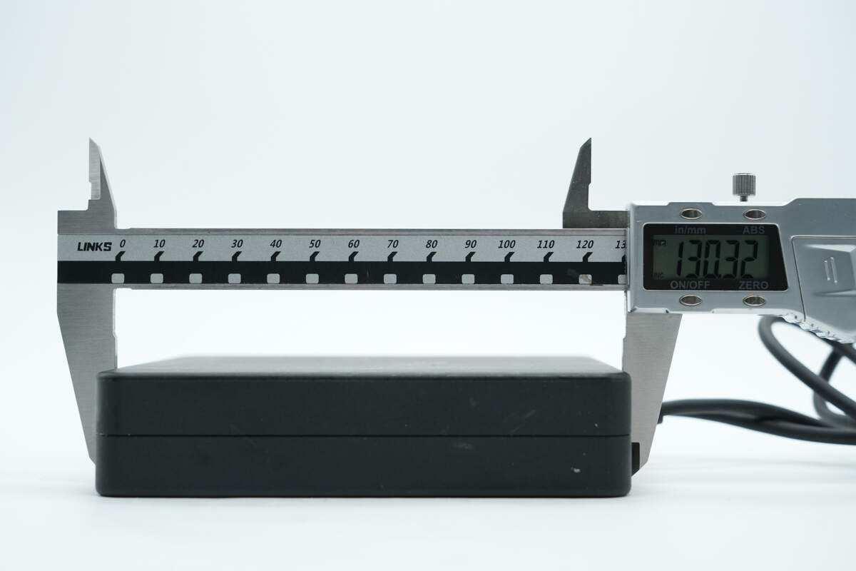
The height of the charger is about 130.32 mm (5.13 inches).
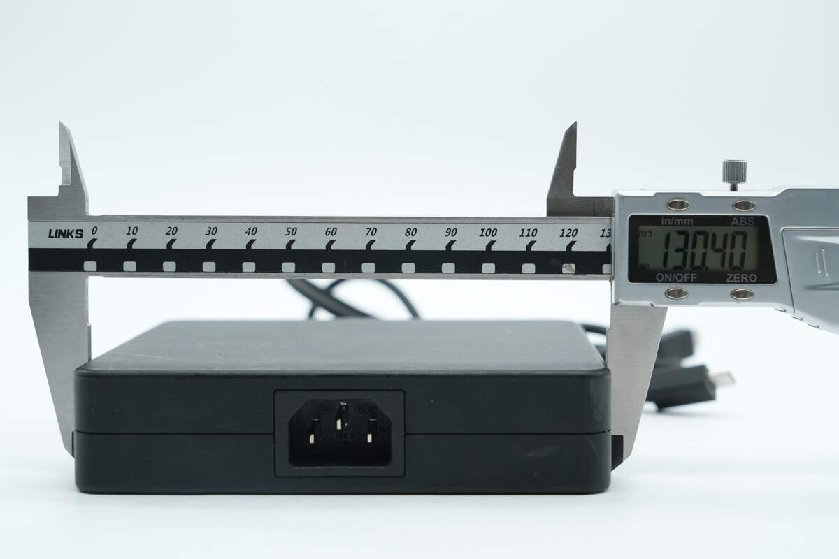
The width is about 130.4 mm (5.13 inches).
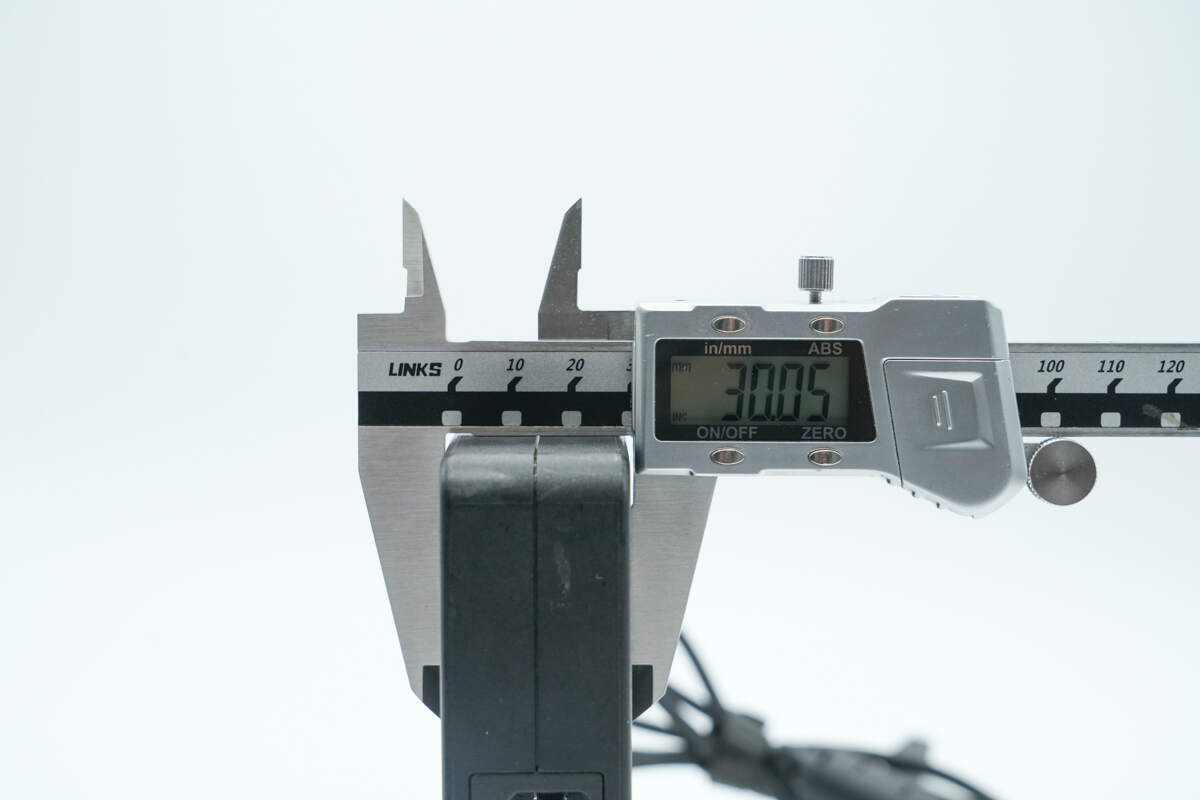
The thickness is about 30.05 mm (1.18 inches).
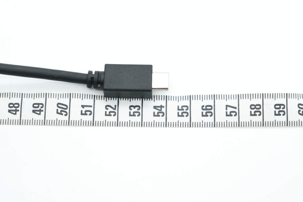
The length of the cable is about 54 cm (21.26 inches).
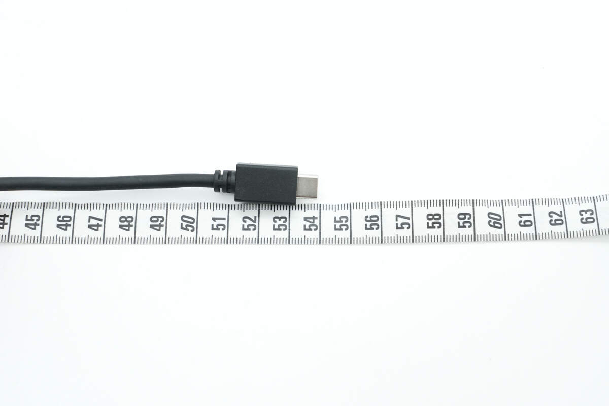
The length of the other cable is also about 54 cm (21.26 inches).
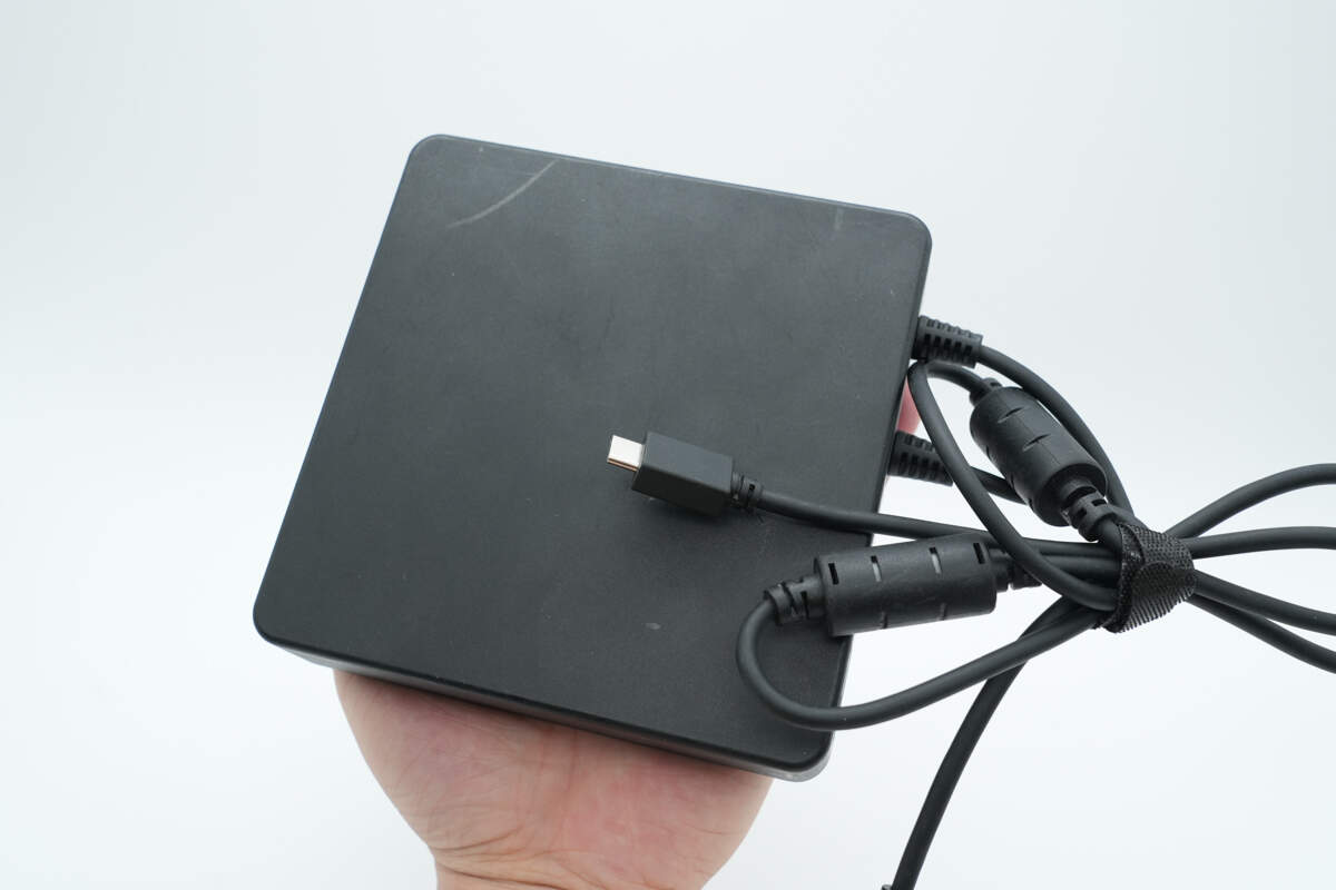
That's how big it is in the hand.
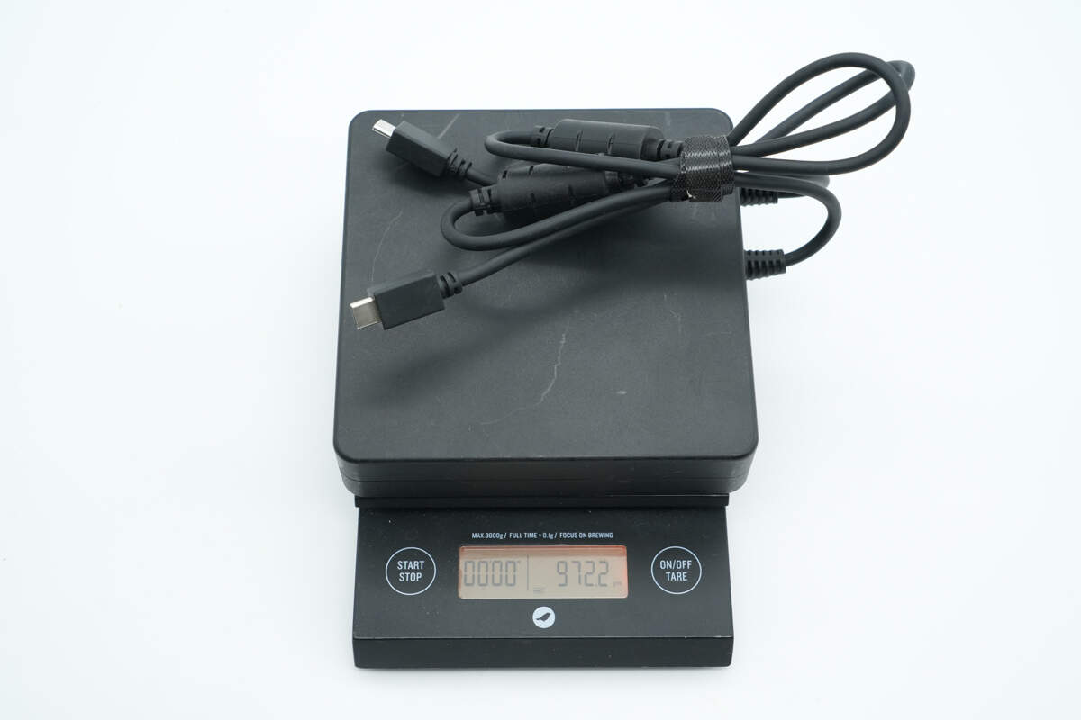
The weight is about 972 g (34.29 oz).
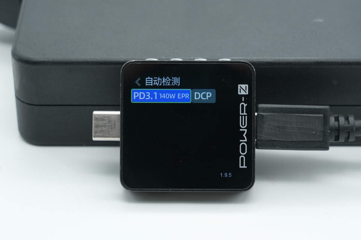
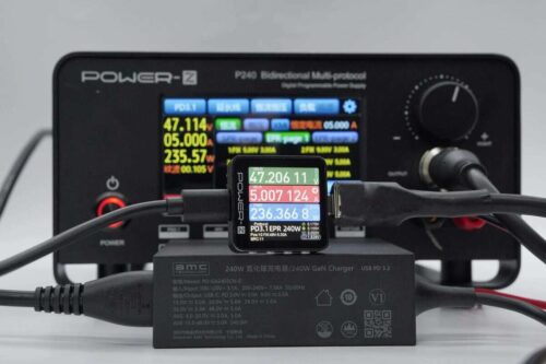
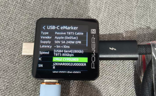
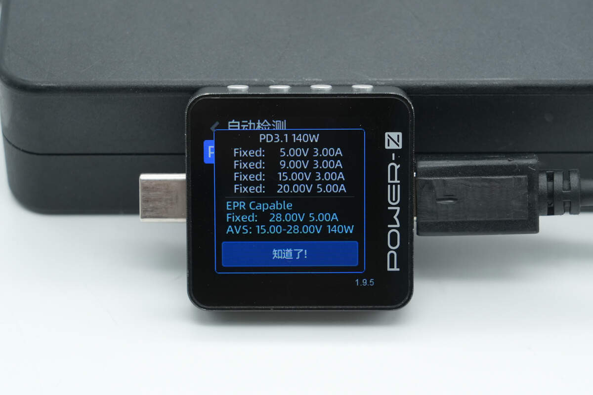
ChargerLAB POWER-Z KM003C shows that the USB-C cable supports PD3.1 and DCP charging protocols.
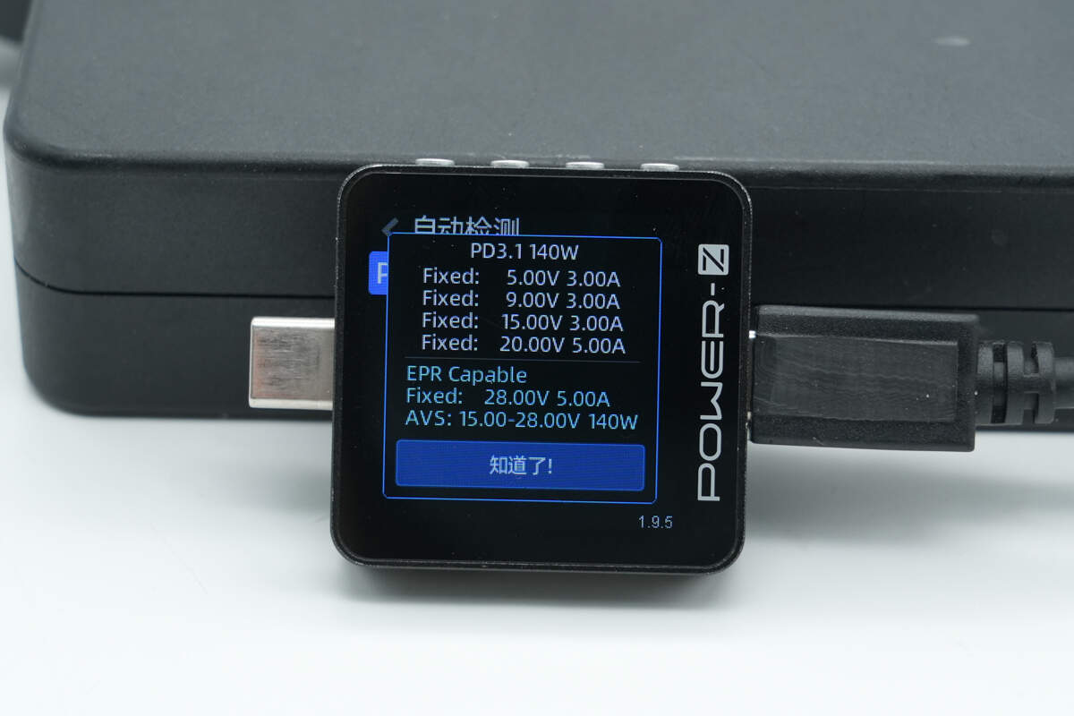
And it has five fixed PDOs of 5V3A, 9V3A, 15V3A, 20V5A, and 28V5A. It has one set of AVS, which is 15-28V 140W.
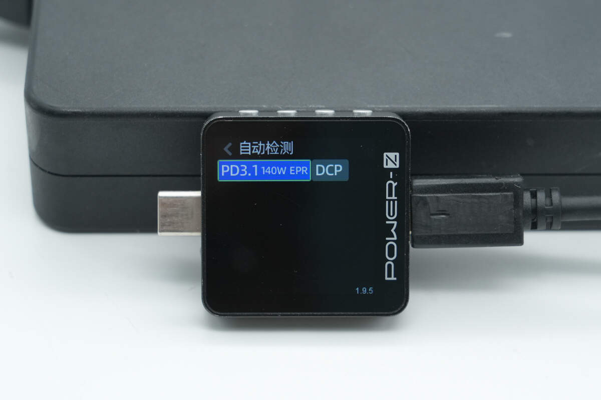
The other USB-C cable supports the same protocols.
The PDO messages are also identical.
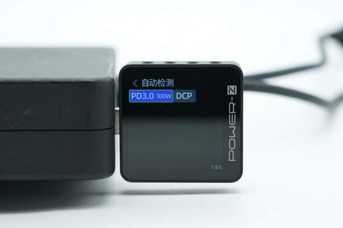
The USB-C port supports PD3.0 and DCP charging protocols.
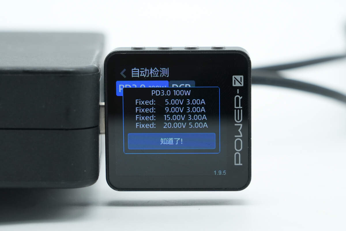
And it has four fixed PDOs of 5V3A, 9V3A, 15V3A, and 20V5A.
Teardown
Next, let's take it apart to see its internal components and structure.
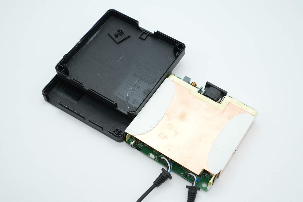
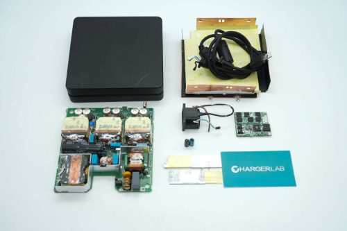
Remove the casing and take out the PCBA module.
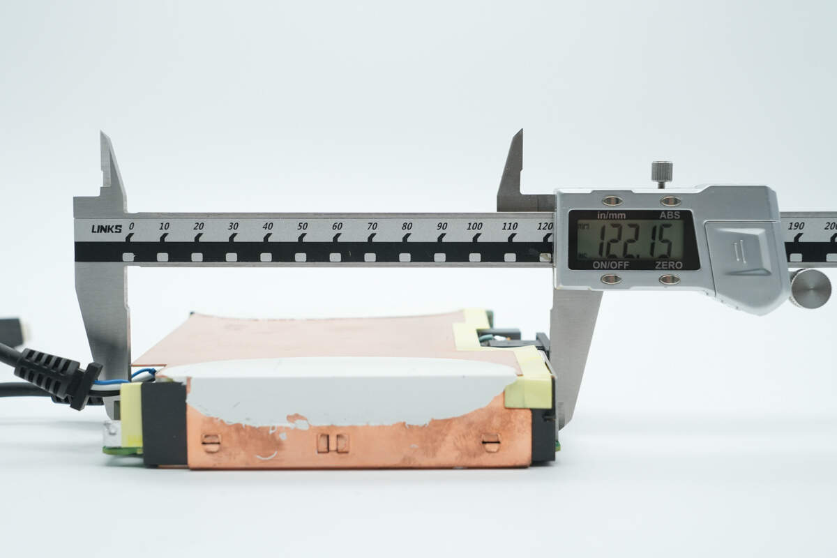
The length of the PCBA module is about 122.15 mm (4.81 inches).
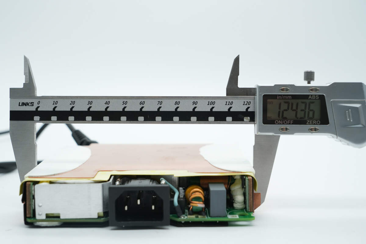
The width is about 124.36 mm (4.9 inches).
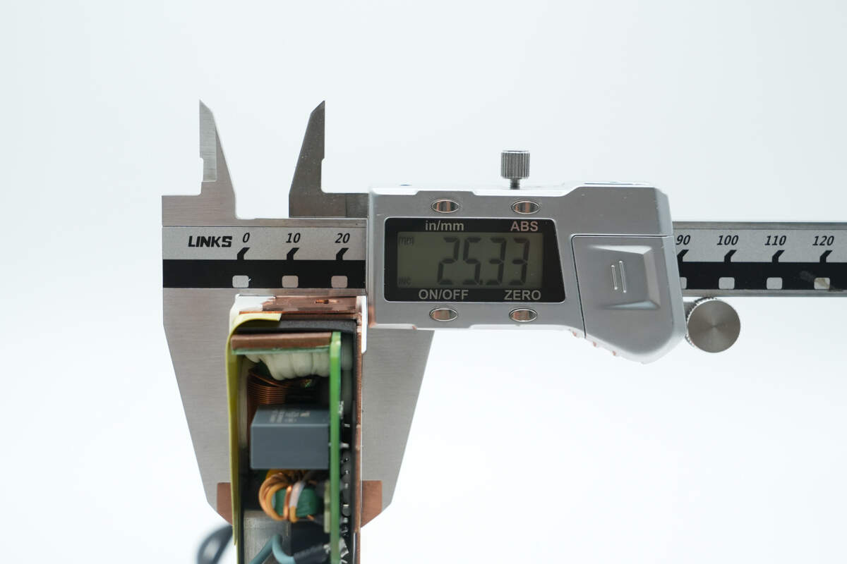
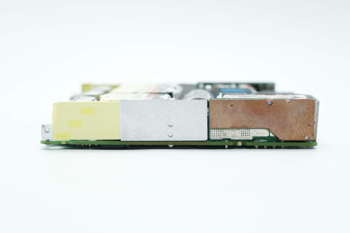
The thickness is about 25.33 mm (1 inch).
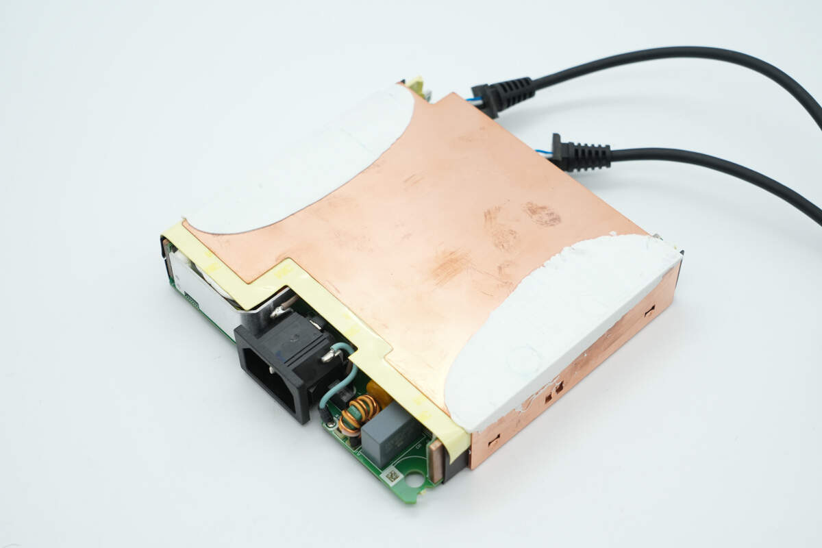
The PCBA module is covered by a copper heat sink plate, with adhesive applied on both sides for reinforcement.
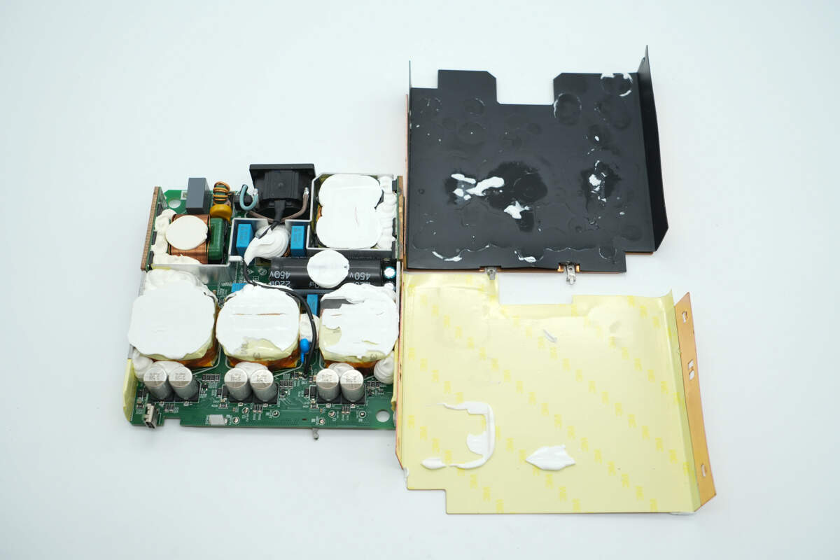
Remove the heat sink. Insulation tape and Mylar sheets are attached to the inside of the heat sink.
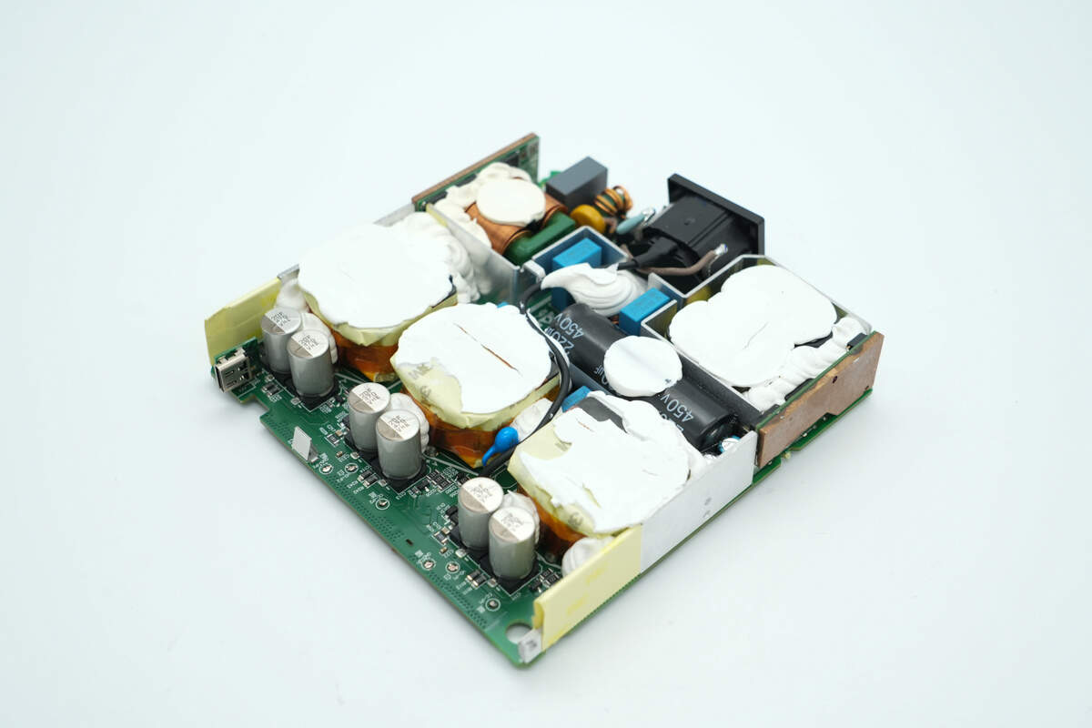
The common mode chokes, PFC boost inductor, transformers, and other components on the front side of the PCBA module are reinforced with adhesive.
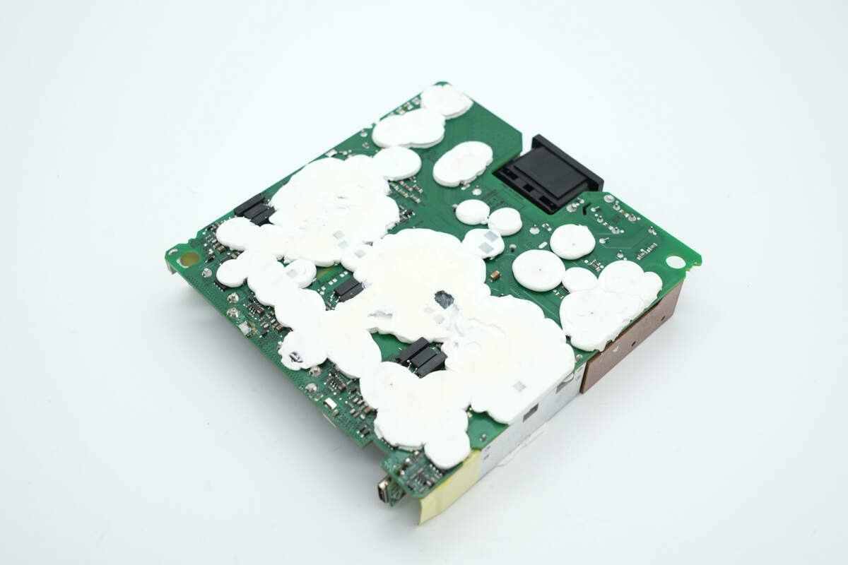
The components on the back are also secured with white adhesive.
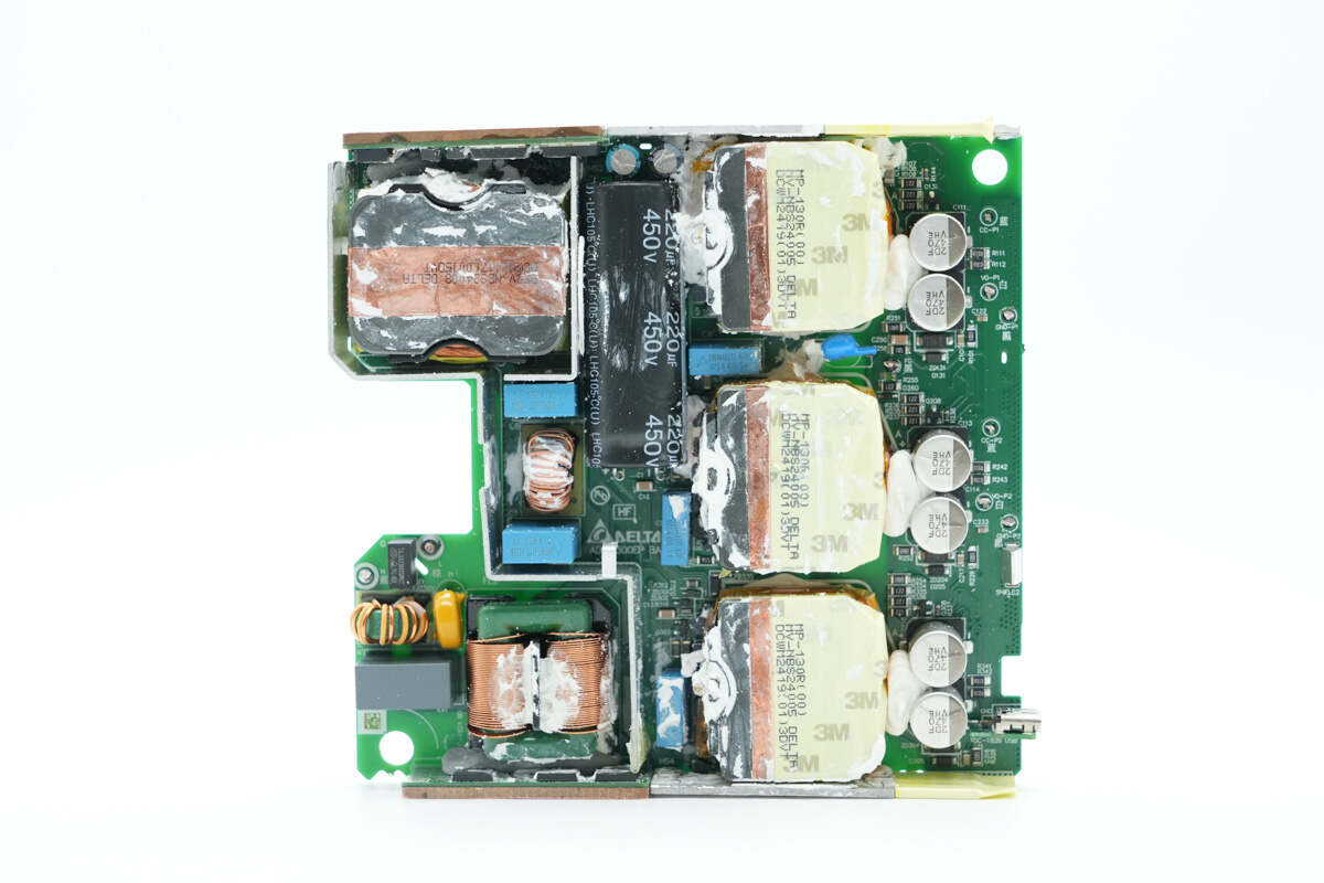
Clean off the white adhesive. On the left side are the input EMI filtering circuit and the PFC boost circuit, while on the right side are three switching power supply transformers and the output filter capacitors.
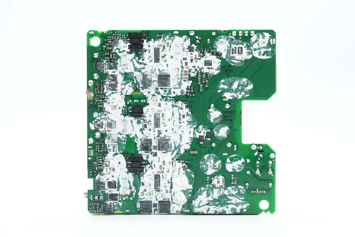
On the back side are the PFC boost controller, controllers for the three switching power supply circuits, primary MOSFETs, synchronous rectification controllers, synchronous rectifiers, protocol chips, and more.
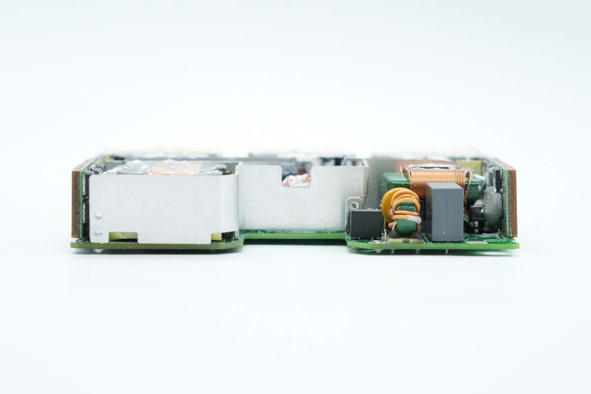
At the front end of the PCBA module, the right section contains components such as a time-delay fuse and common mode chokes.
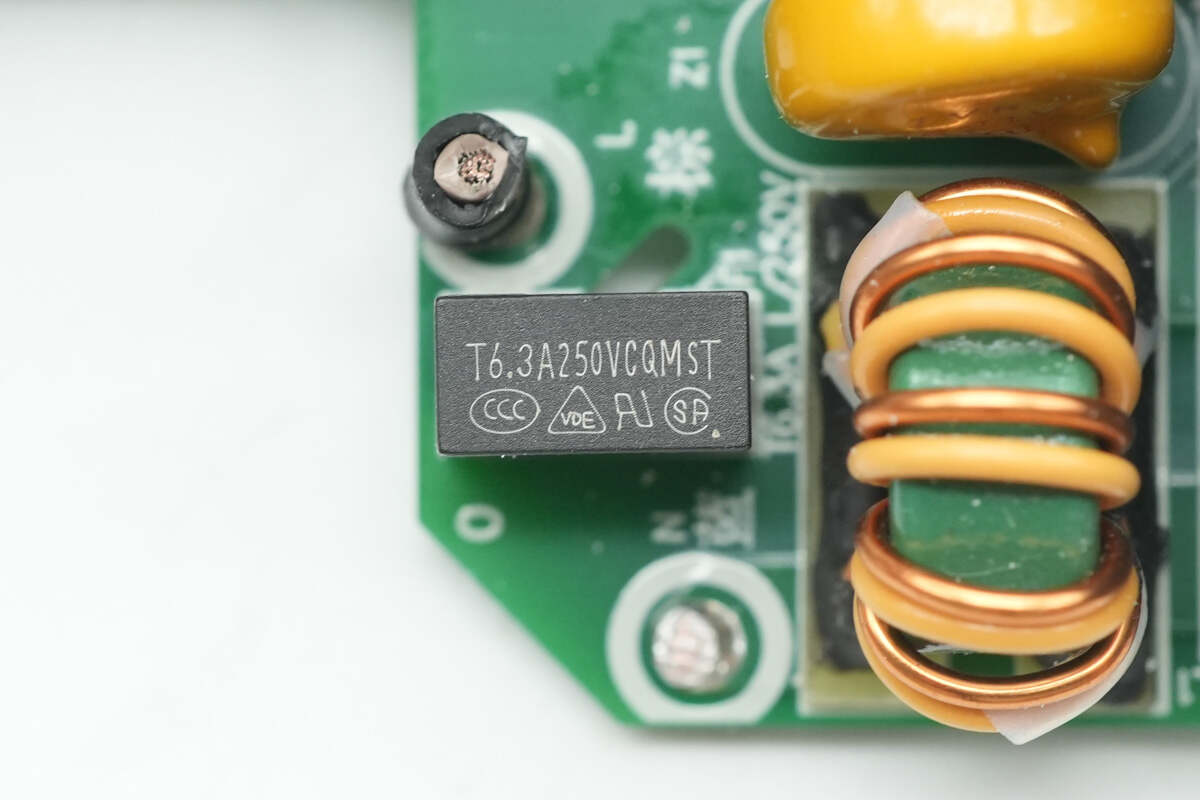
The time-delay fuse is rated at 6.3A, 250V.
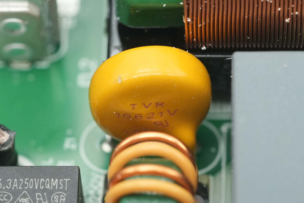
Close-up of the TVR10621V varistor.
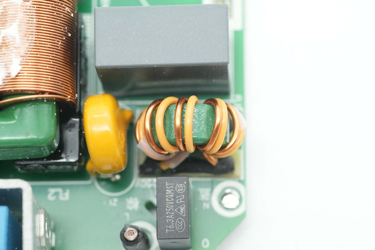
The common mode choke is wound with dual wires and is used to filter out EMI interference.
The secondary common mode choke is wound with flat copper strips.
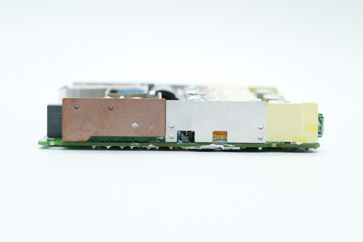
On this side, a PCB with bridge rectifiers is soldered in place, and a copper heat sink is attached to the back of the PCB.
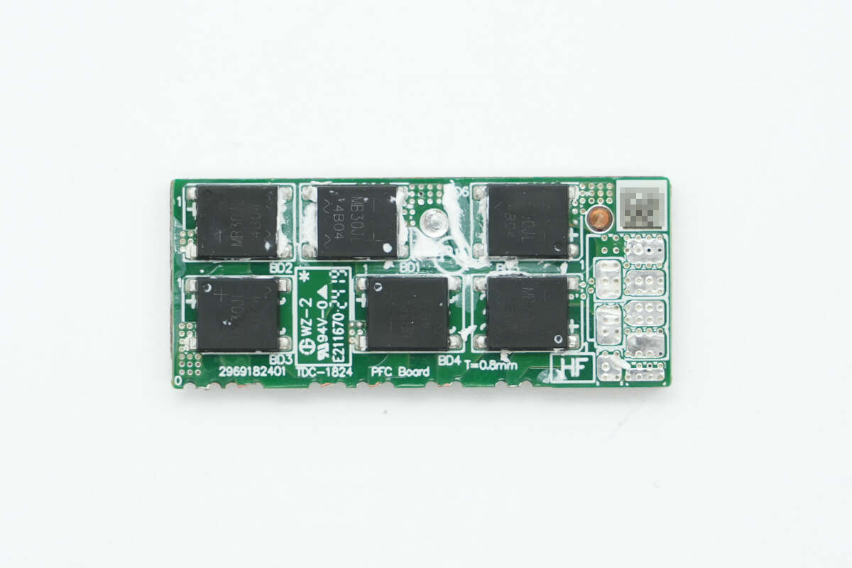
Remove the PCB, and you will see six bridge rectifiers on the front.
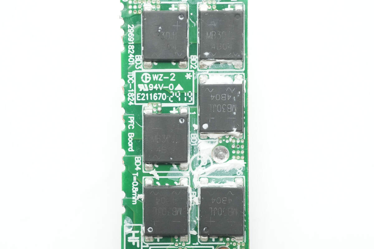
The six bridge rectifiers are of the same model.
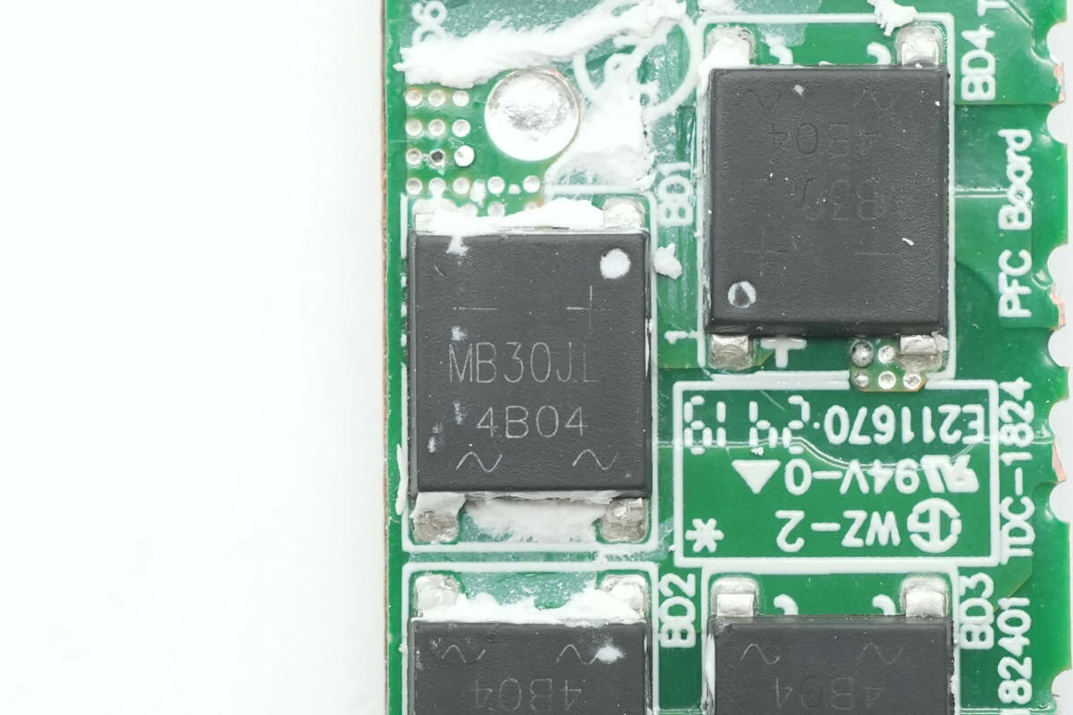
The bridge rectifier is marked with MB30JL and has a rated current of 3A.
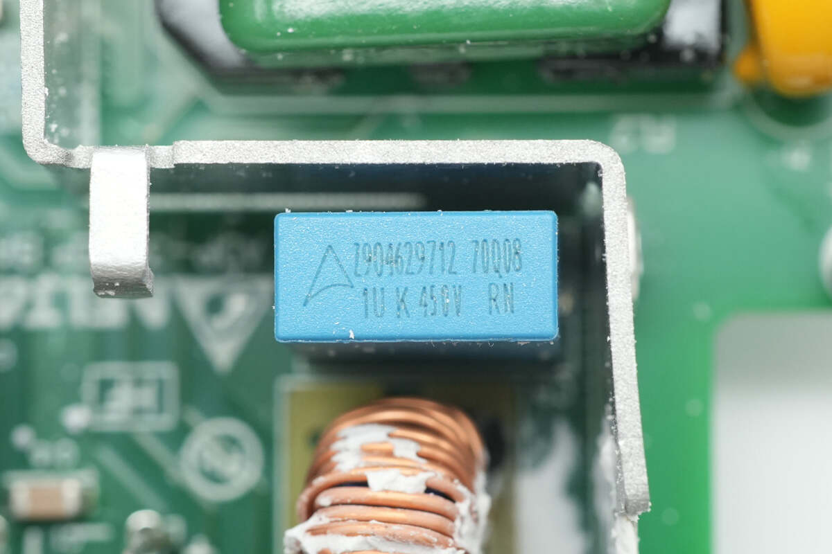
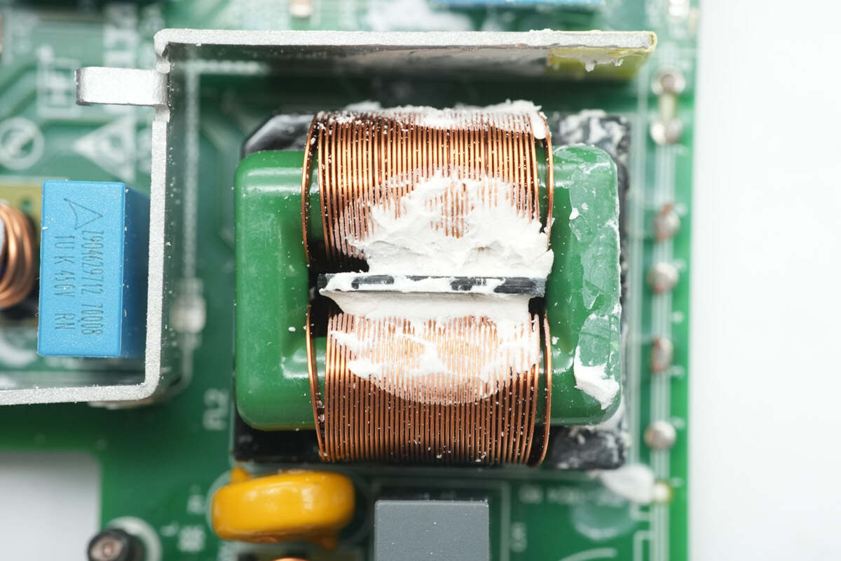
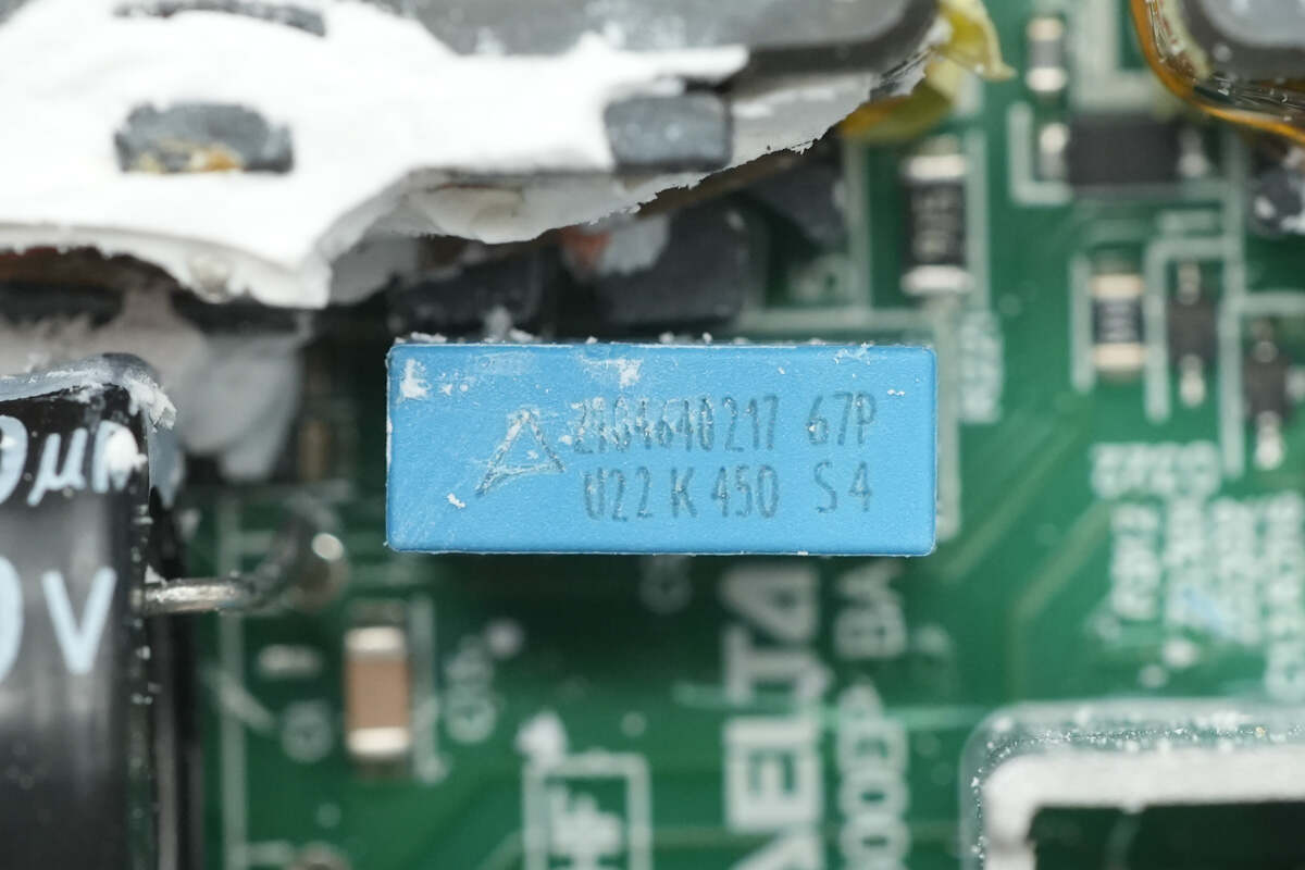
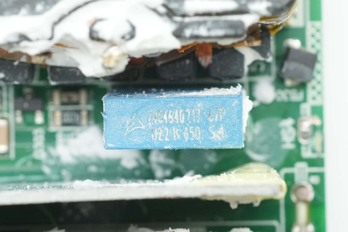
The film filter capacitor is rated at 1μF, 450V.
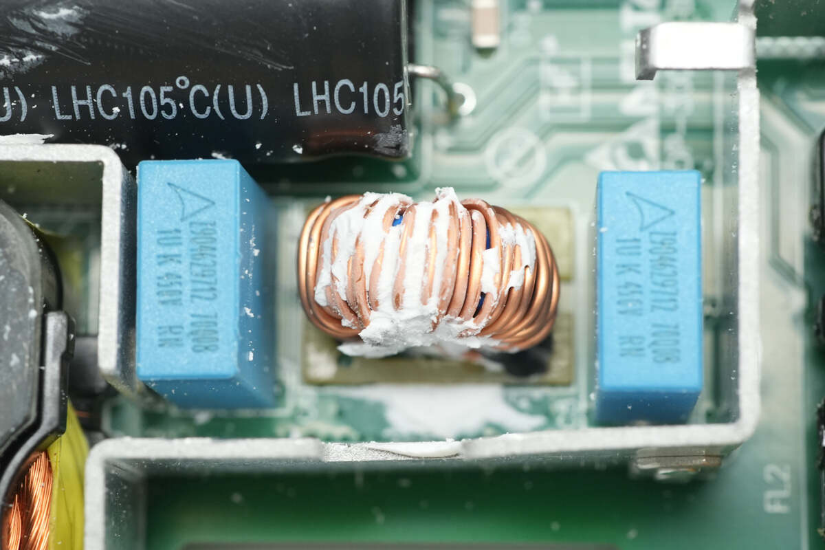
The base of the filter inductor is fitted with a bakelite board.
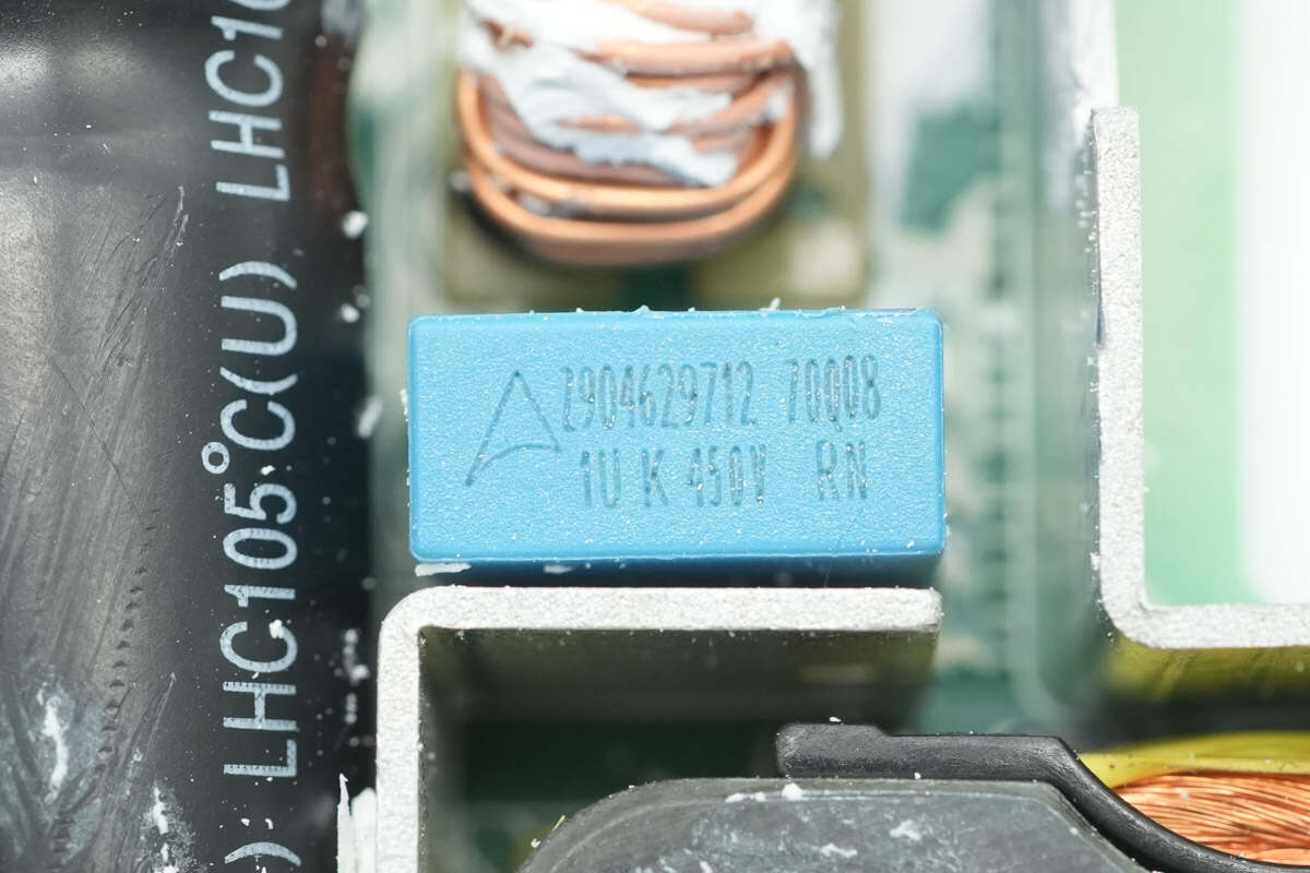
The other film filter capacitor has the same model and specifications.
On the other side, there is a PFC boost rectification PCB.
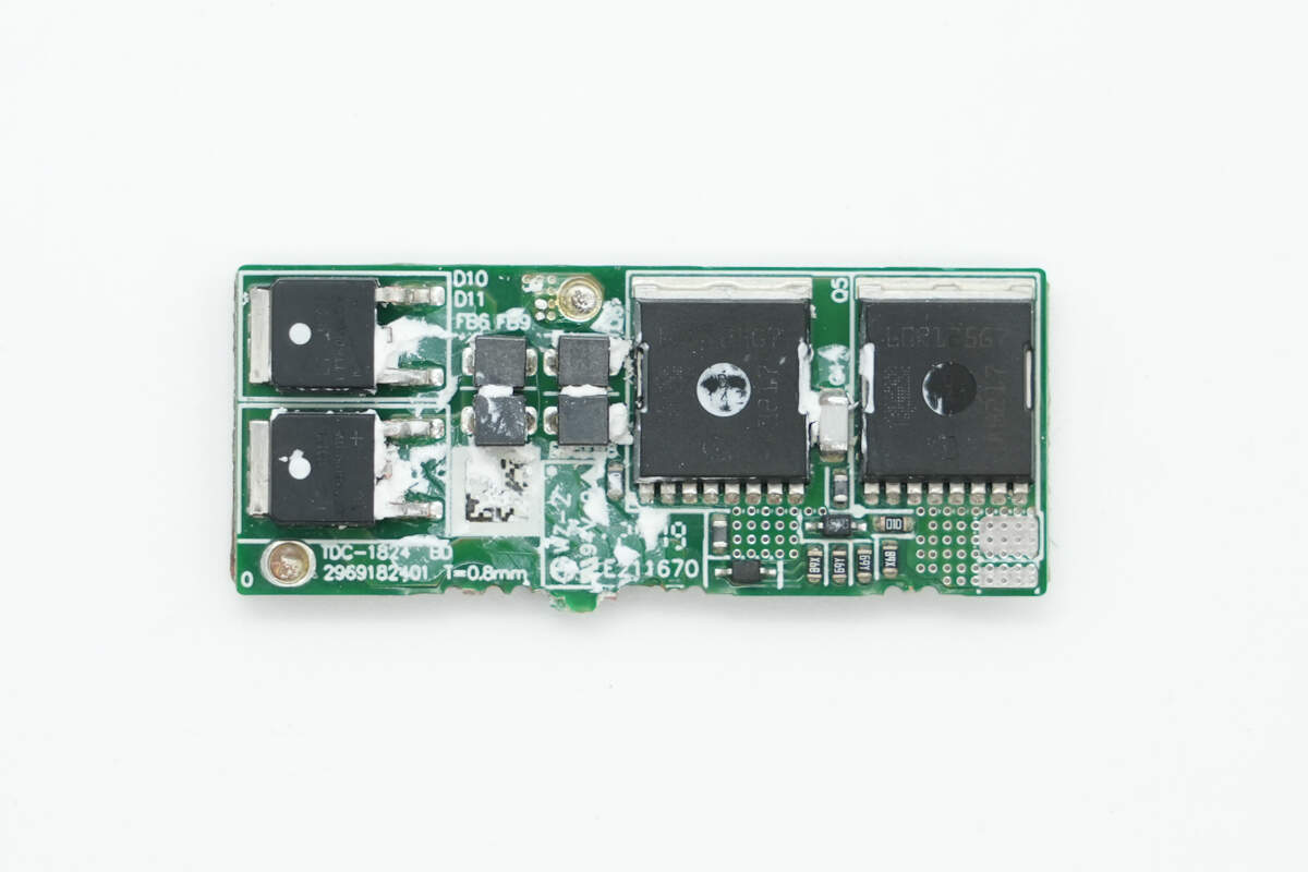
Remove the PCB, and you will see PFC boost MOSFETs and PFC rectifiers on the front.
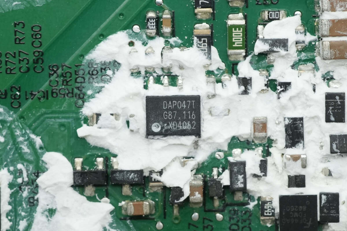
The PFC controller is marked with DAP047T, a custom model developed by Delta.
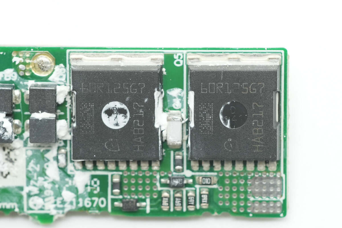
The two PFC boost MOSFETs are from Infineon, model IPT60R125G7, part of the CoolMOS G7 series. They have a voltage rating of 650V, an on-resistance of 125mΩ, and use a PG-HSOF-8 package.
Close-up of the PFC boost inductor.
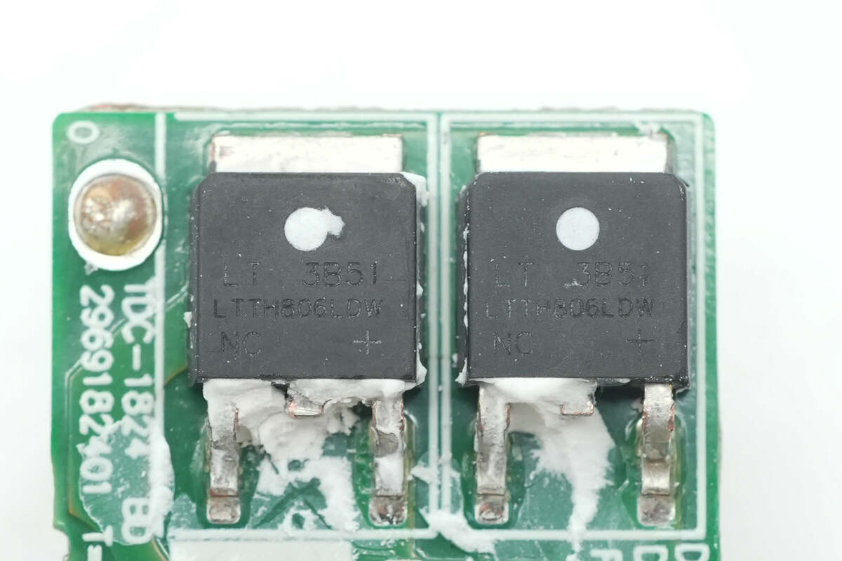
The two PFC rectifiers are from LITEON, model LTTH806LDW. They are ultra-fast recovery diodes rated at 600V, 8A, and come in a DPAK package.
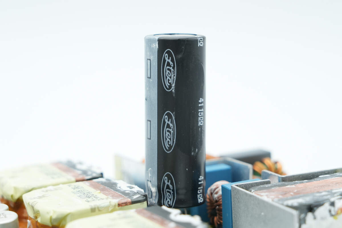
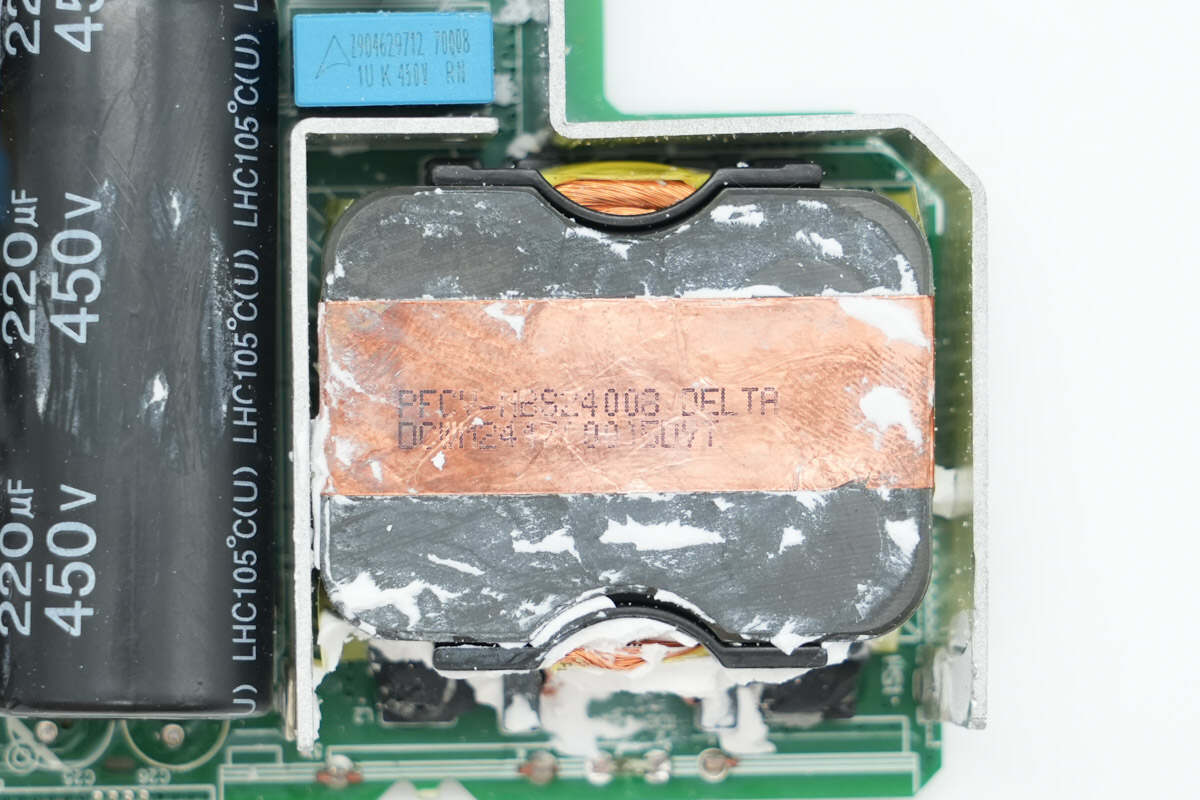
The high-voltage filter electrolytic capacitor is from LTEC.
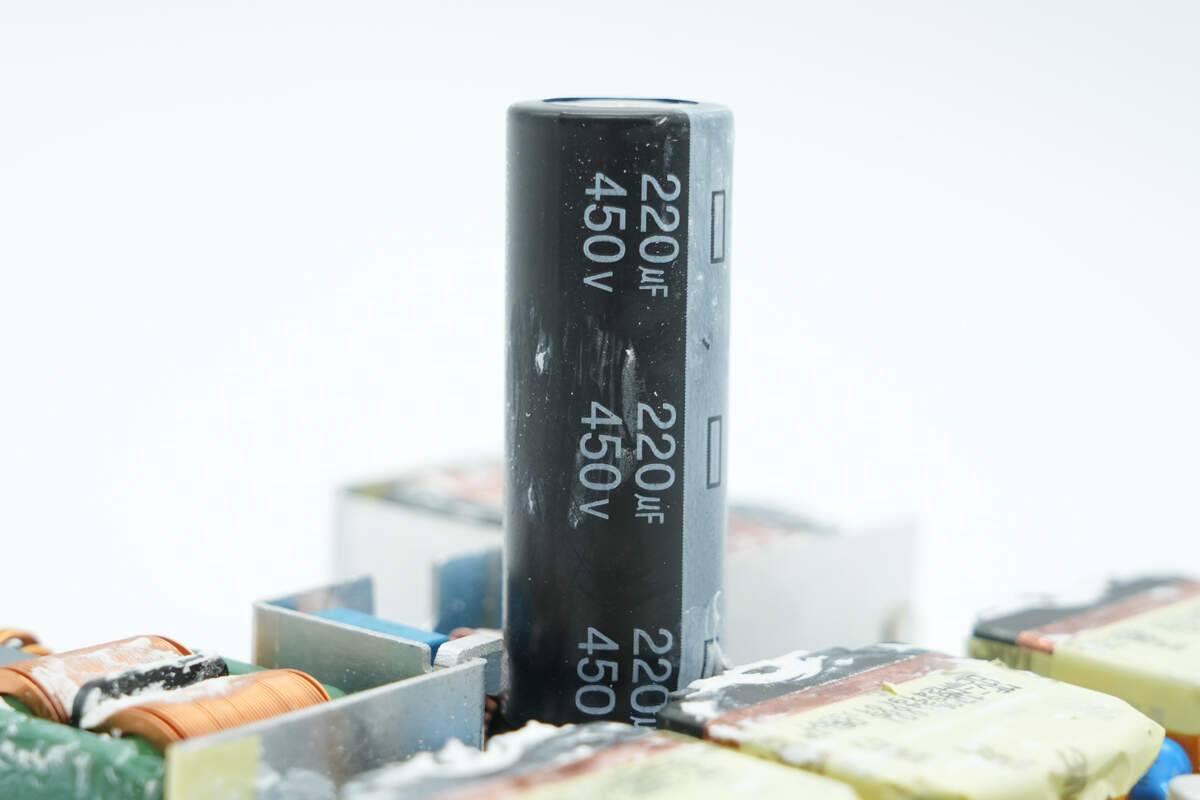
Its specifications are 450V, 220μF.
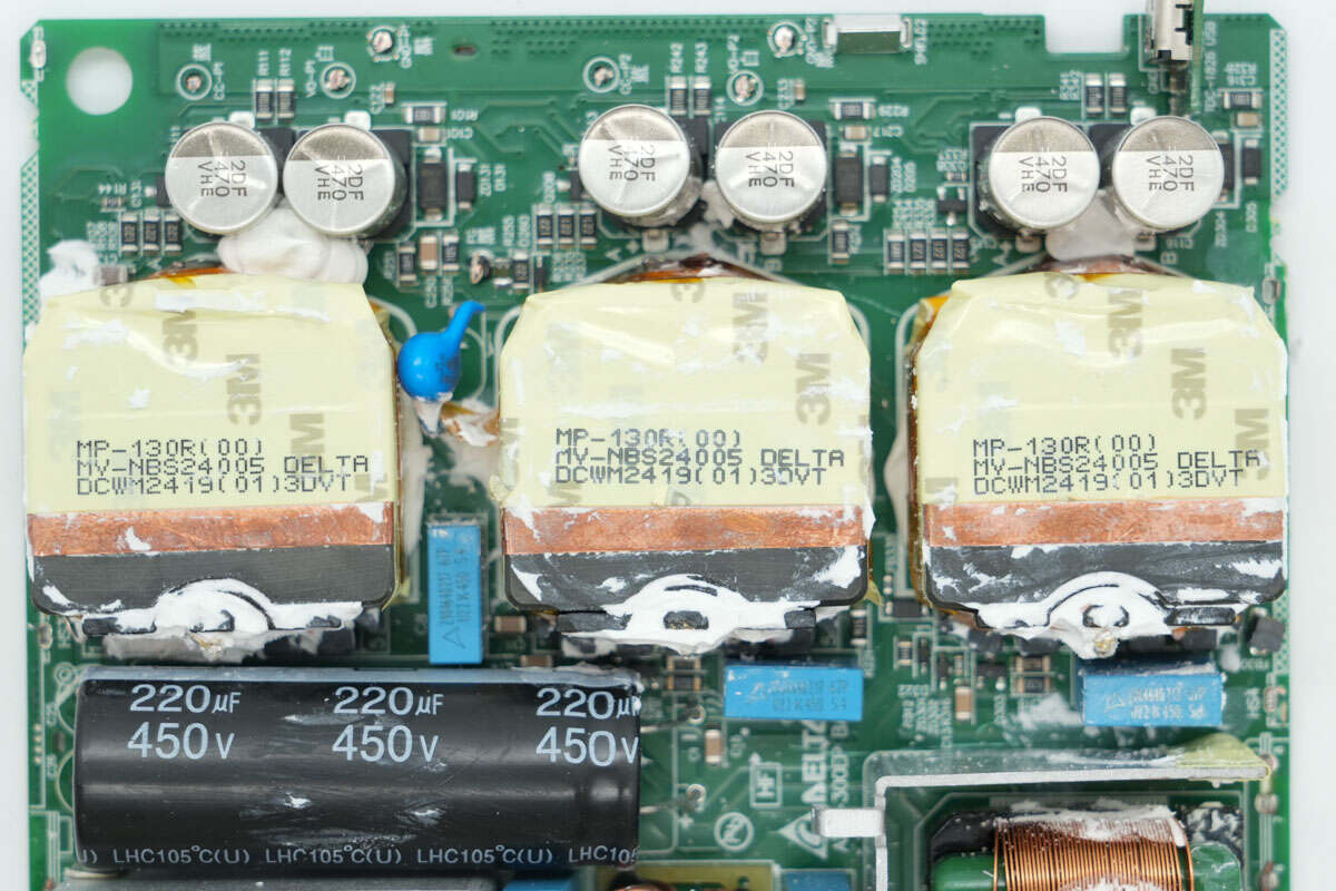
All three switching power supply circuits are equipped with resonant capacitors, transformers, output filter capacitors, and other components. The three transformers have the same part number and are reinforced with adhesive.
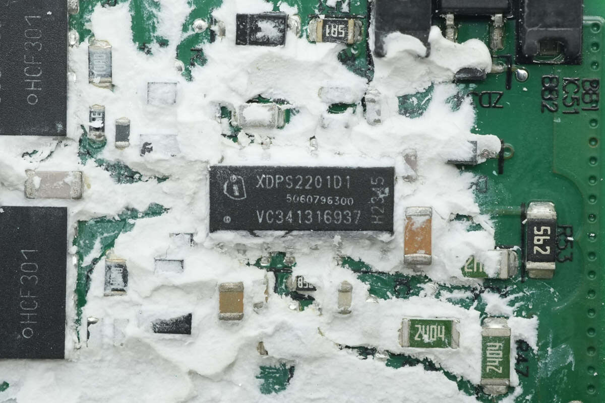
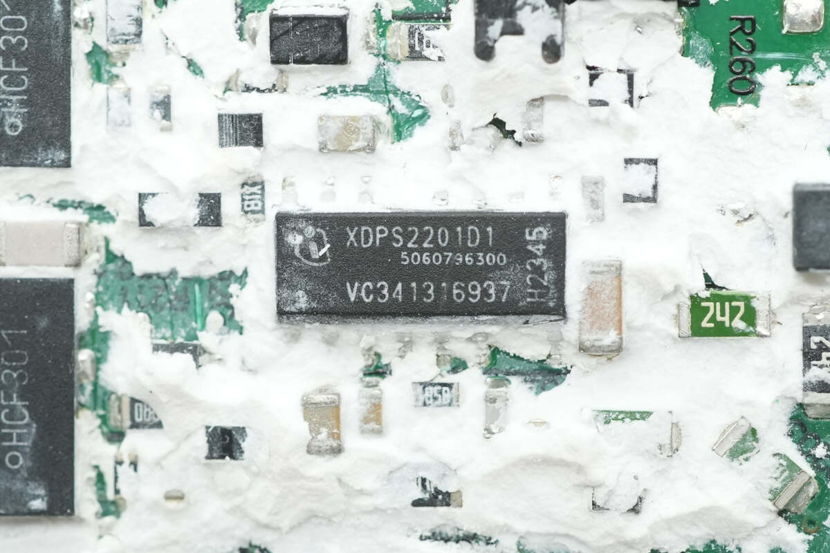
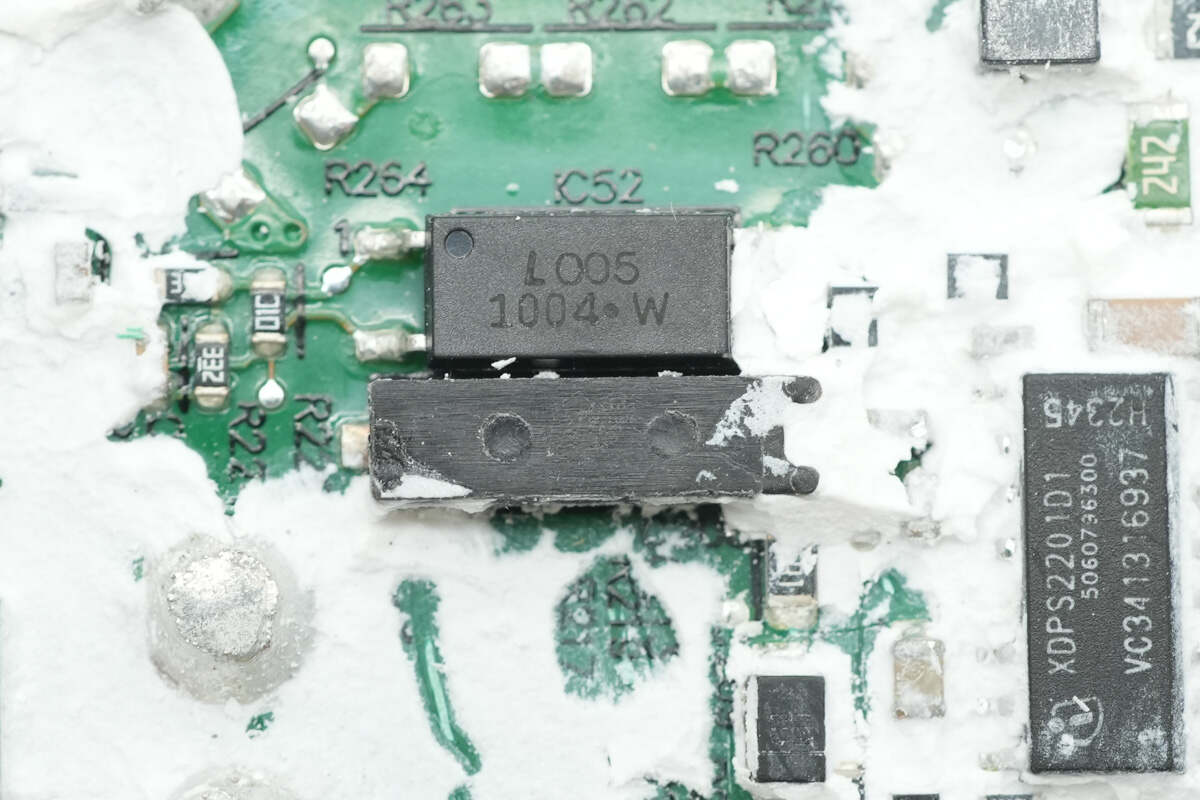
All three circuits use the same design scheme, with the primary controllers all being Infineon chips marked XDPS2201D1.
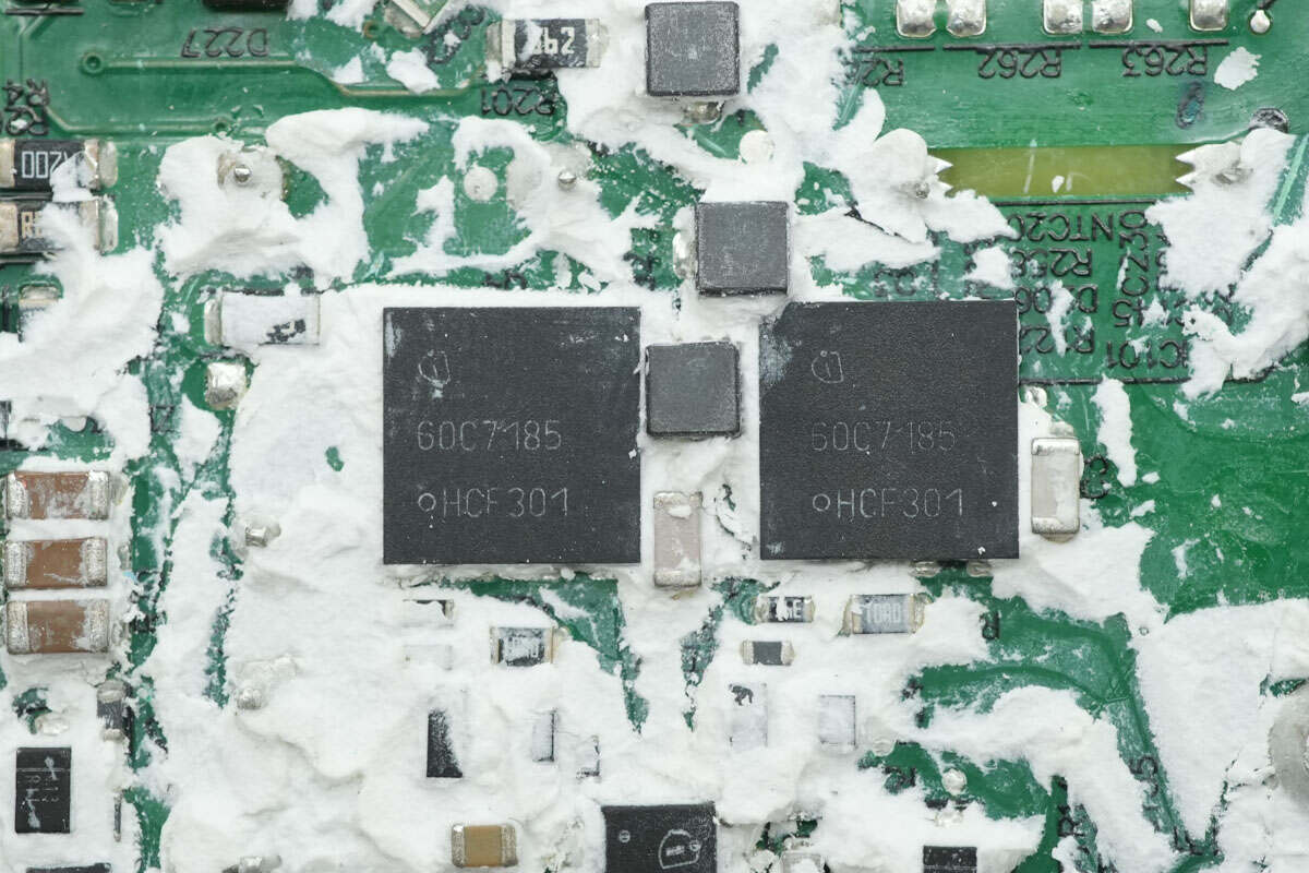
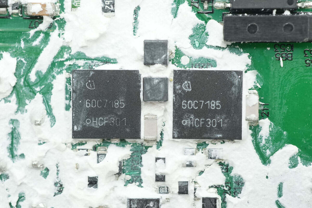
The primary MOSFETs are from Infineon, marked with 60C7185, model IPL60R185C7. They are NMOS devices with a voltage rating of 650V, an on-resistance of 185mΩ, and come in a ThinPAK 8x8 package.
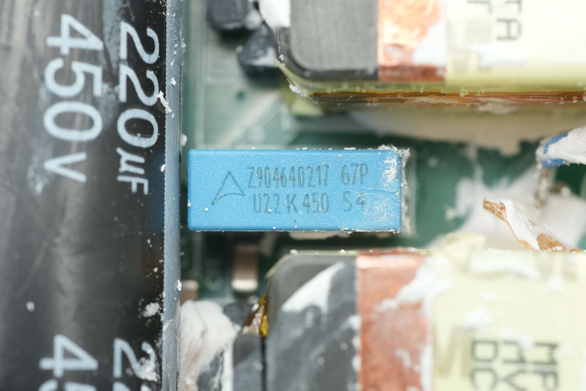
The resonant capacitor is rated at 0.22μF, 450V.
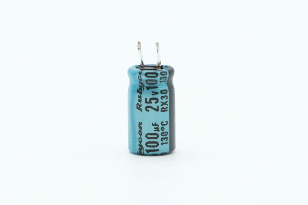
The capacitor supplying power to the master control chip is from Rubycon, rated at 25V, 100μF.
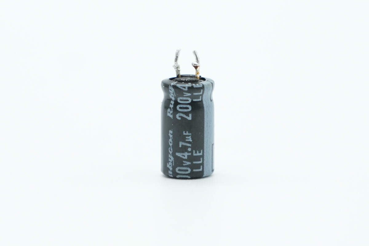
The other capacitor is also from Rubycon, rated at 200V, 4.7μF.
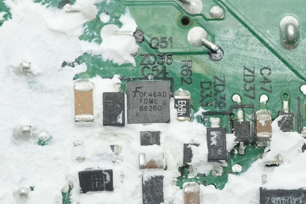
The MOSFET supplying power to the master control chip is from Onsemi, model FDMC86260. It is an NMOS with a voltage rating of 150V, an on-resistance of 34mΩ, and comes in a Power33 package.
Close-up of the LITEON LTV-1004 optocoupler, used for output voltage feedback, with plastic mounting brackets soldered on both sides for support.
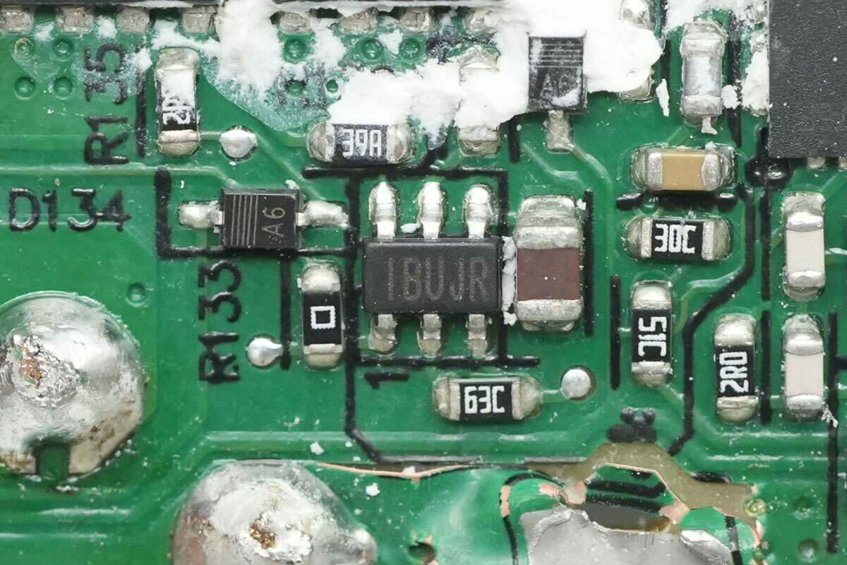
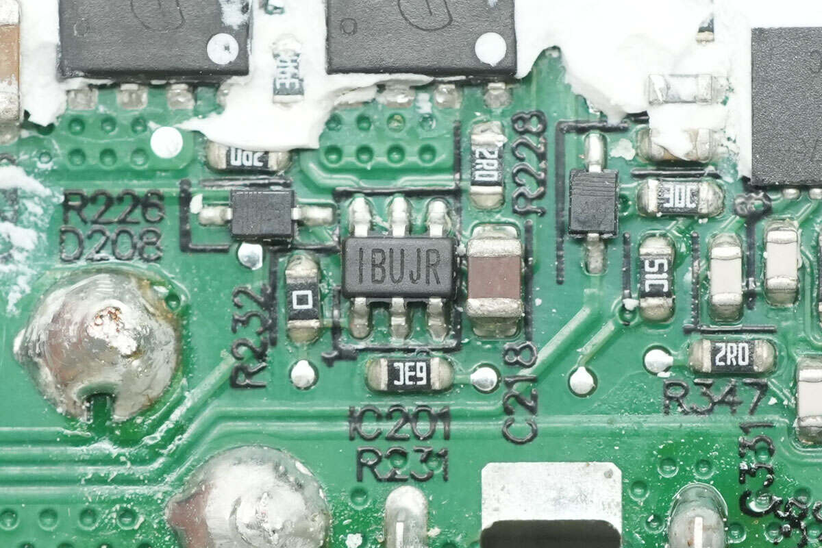
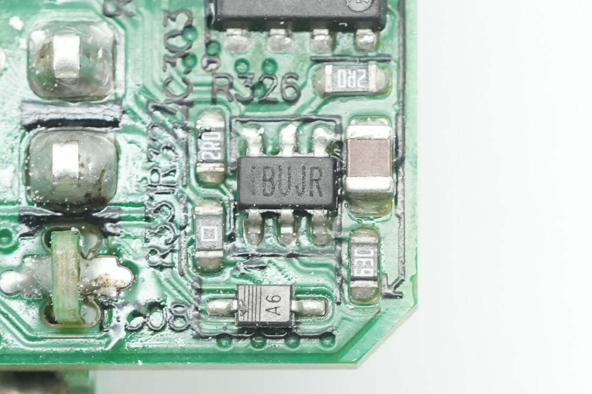
The synchronous rectifier controller is marked with IBHJR, model MP6908A, from MPS. It supports a maximum operating frequency of 600kHz and multiple modes, including DCM, CCM, QR, and ACF. It can be used for both high-side and low-side applications, features ringing detection to prevent false turn-on, and comes in a TSOT23-6 package.
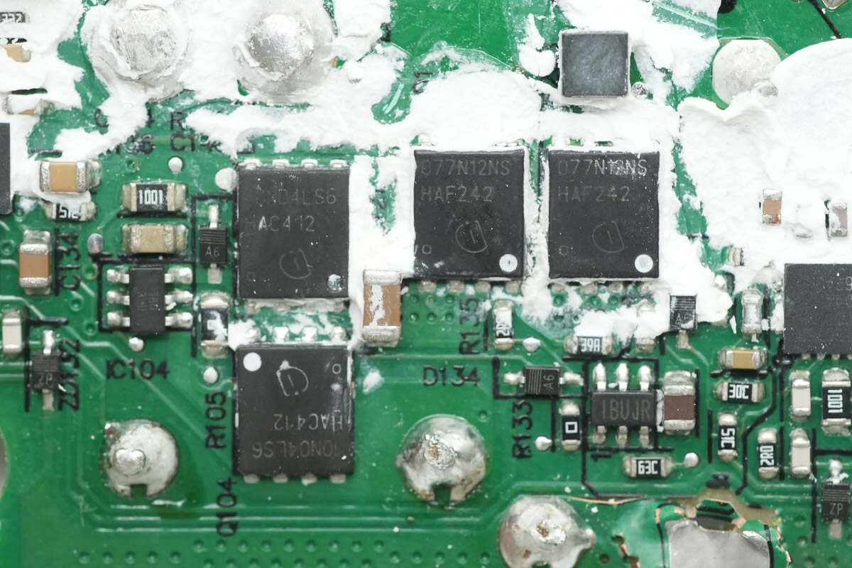
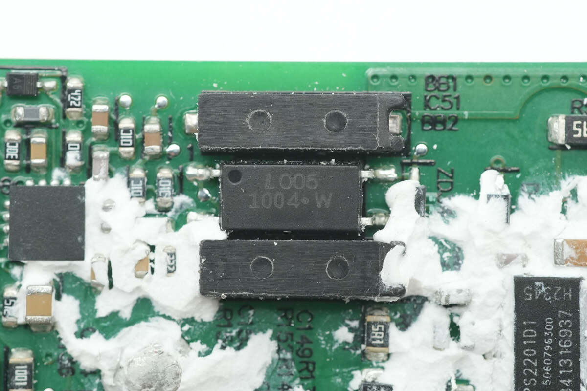
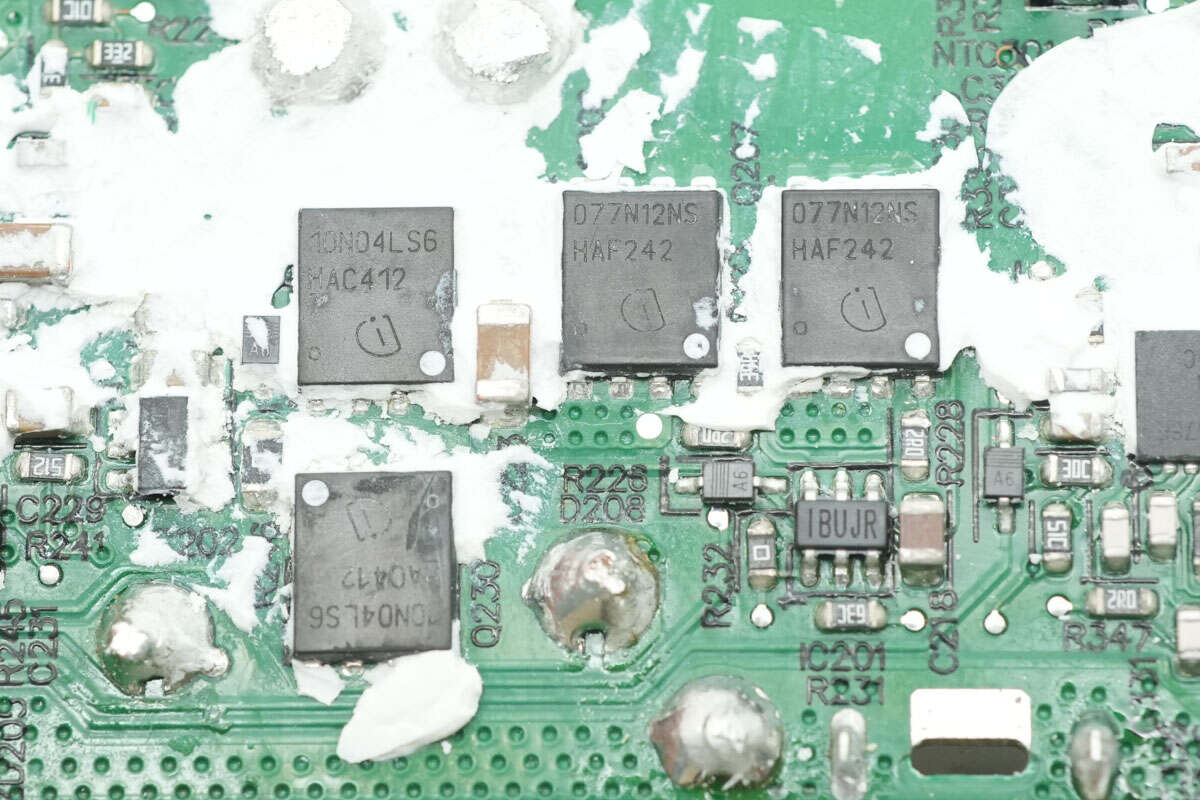
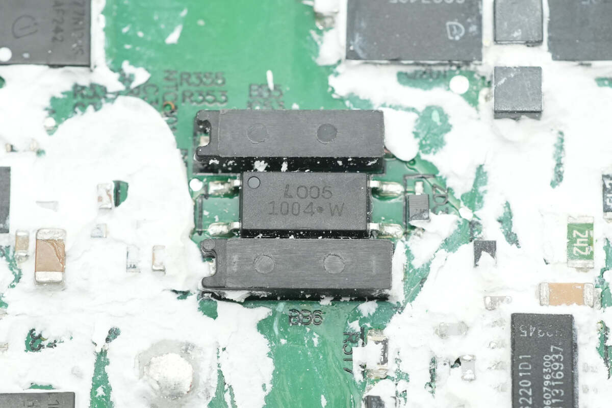
The two synchronous rectifiers use Infineon BSC077N12NS3 G MOSFETs, rated at 120V with an on-resistance of 7.7mΩ, and come in PG-TDSON-8 packages. The two VBUS MOSFETs are Infineon BSC010N04LS6, rated at 40V with an on-resistance of 1mΩ, and use TDSON-8 FL packages.
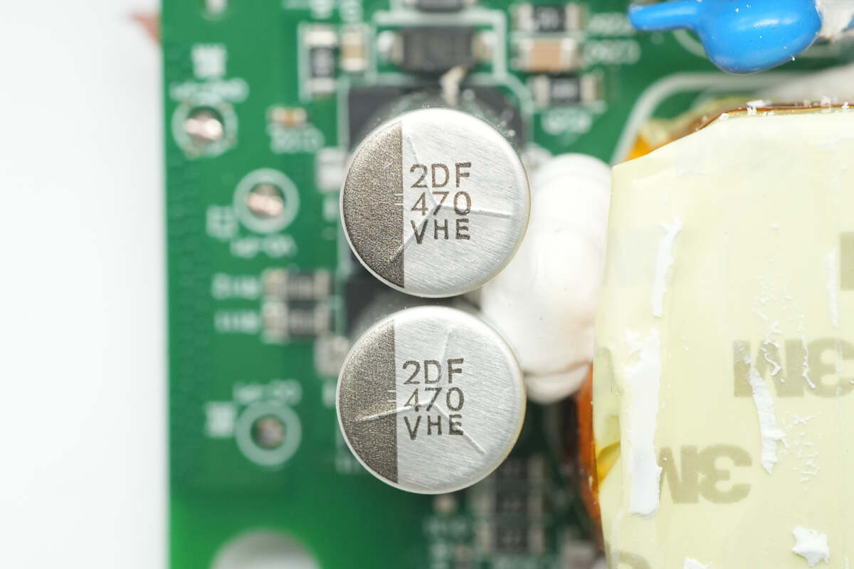
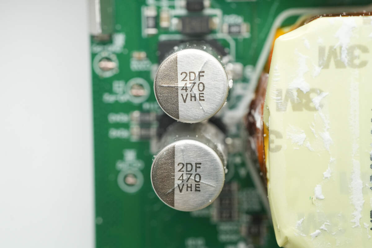
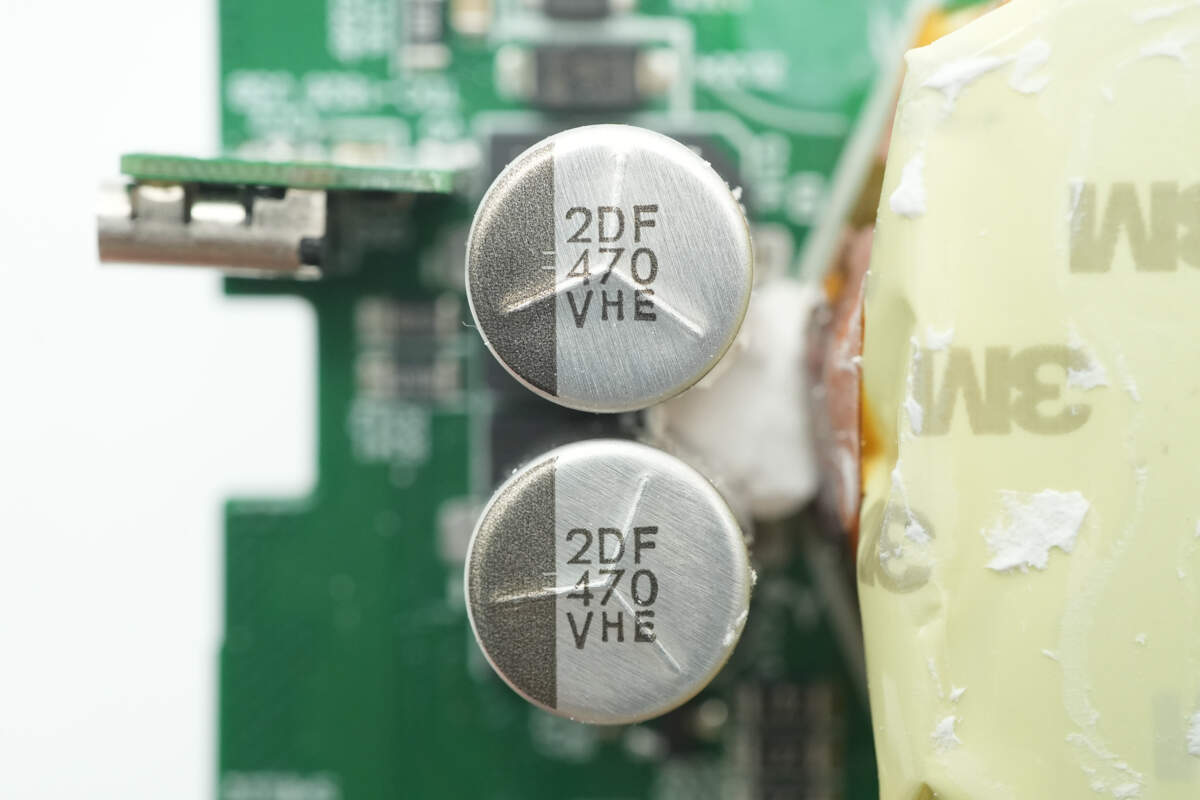
The output filter capacitors are from NCC, part of the HXE series of conductive polymer hybrid aluminum electrolytic capacitors. They support an operating temperature range of -55°C to 135°C and have a specification of 470μF, 35V.
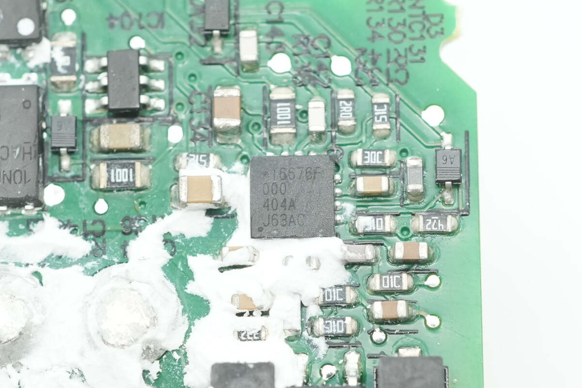
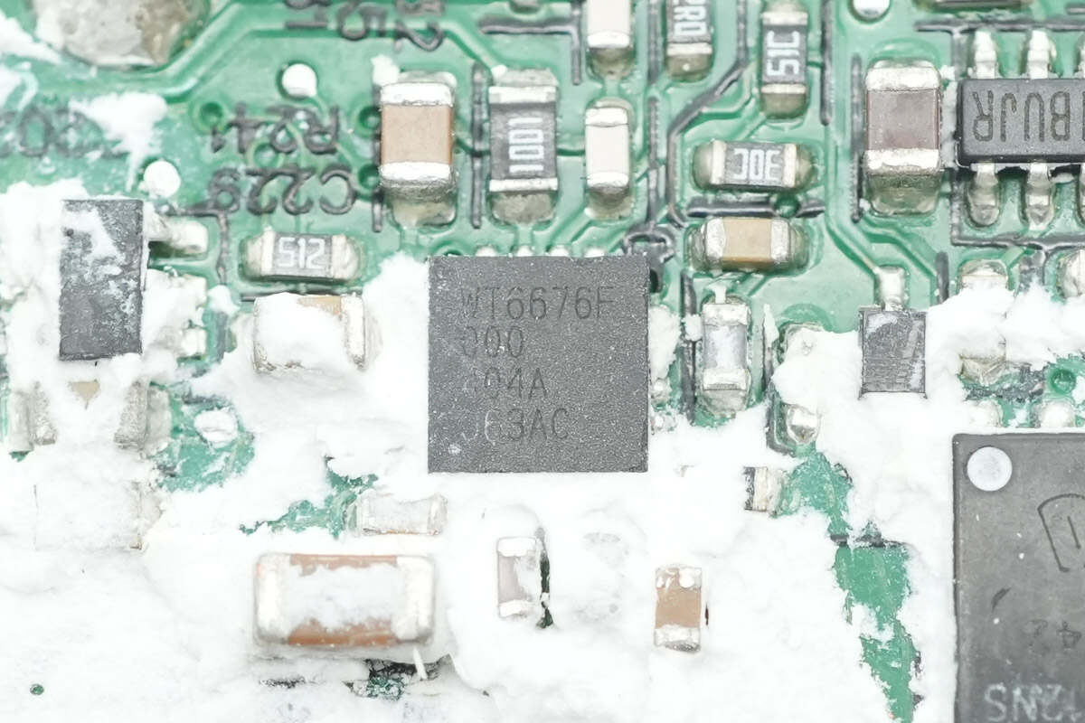
The protocol chip is from Weltrend, model WT6676F. It supports USB PD 3.1, 36V output voltage, and programmable constant voltage and constant current control. It integrates a low-side current sensing amplifier and supports line loss compensation. It also features programmable protection functions, including overvoltage, undervoltage, overcurrent, and over-temperature protection.
The chip has a built-in 10-bit ADC for voltage and current detection, an integrated NMOS load switch driver, an output discharge transistor, and a voltage regulator. It supports PFC control and energy-saving modes, with an input voltage up to 45V, and comes in a QFN-16 package.
A thermistor is soldered to the right side of the chip to monitor the internal temperature of the charger for over-temperature protection.
The master control chip of the second circuit also uses an Infineon chip marked XDPS2201D1.
Both primary MOSFETs also use the Infineon IPL60R185C7.
The resonant capacitors have the same part number.
Close-up of the LITEON LTV-1004 optocoupler.
Close-up of the MPS MP6908A synchronous rectifier controller.
The two synchronous rectifiers and the two VBUS MOSFETs also use Infineon BSC077N12NS3 G and BSC010N04LS6, respectively.
The second set of output filter capacitors has the same part number.
Close-up of the Weltrend WT6676F protocol chip.
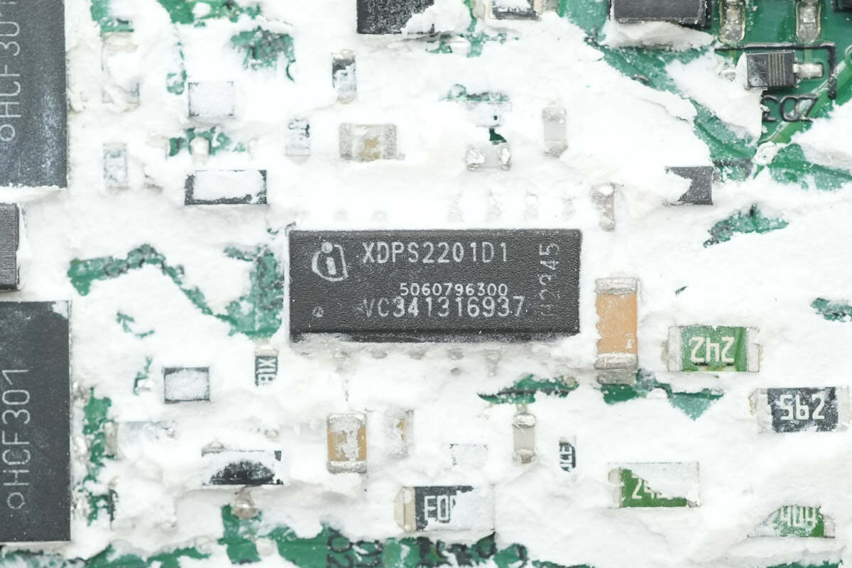
The master control chip of the third circuit also uses an Infineon chip marked XDPS2201D1.
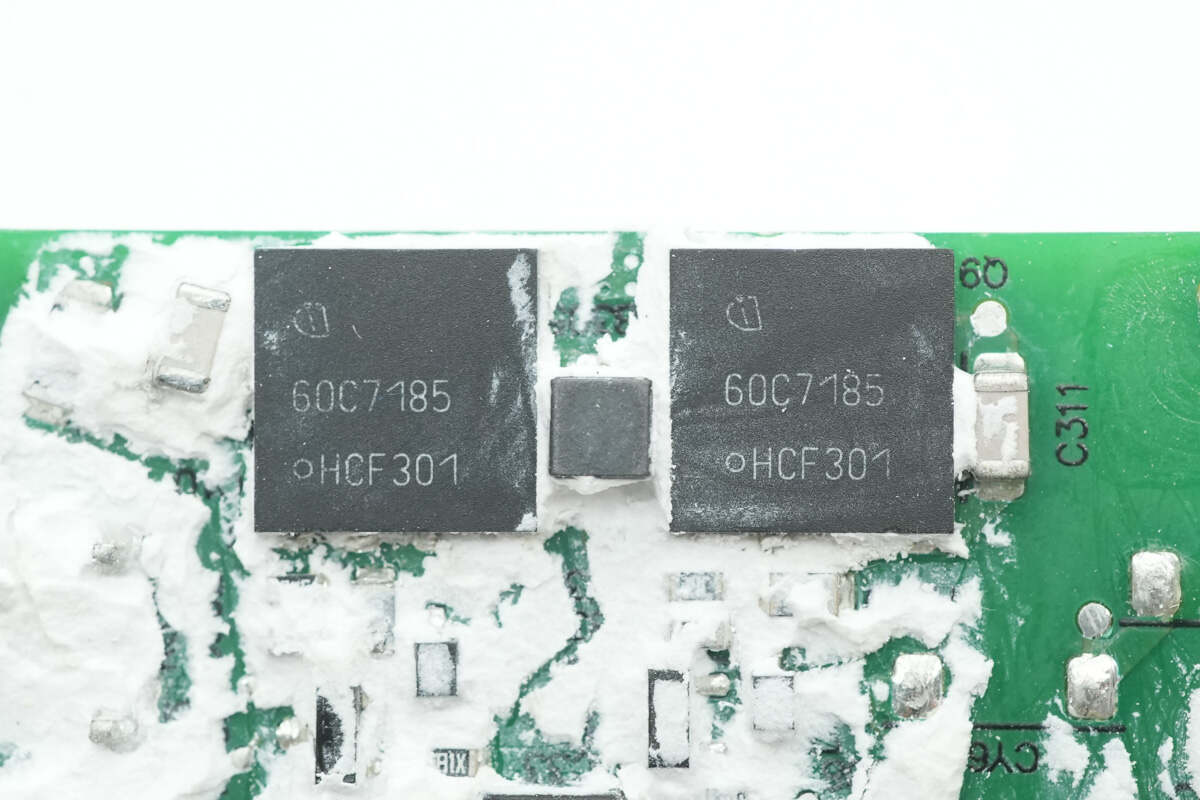
Close-up of two Infineon IPL60R185C7 primary MOSFETs.
The third resonant capacitor also has the same part number.
Close-up of the LITEON LTV-1004 optocoupler.
Close-up of the MPS MP6908A synchronous rectifier controller.
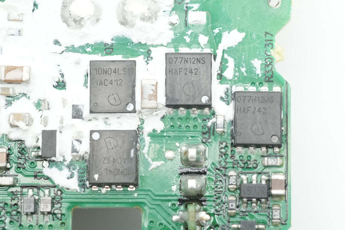
Close-up of the Infineon BSC077N12NS3 G synchronous rectifiers and BSC010N04LS6 VBUS MOSFETs.
The third set of output filter capacitors also has the same part number.
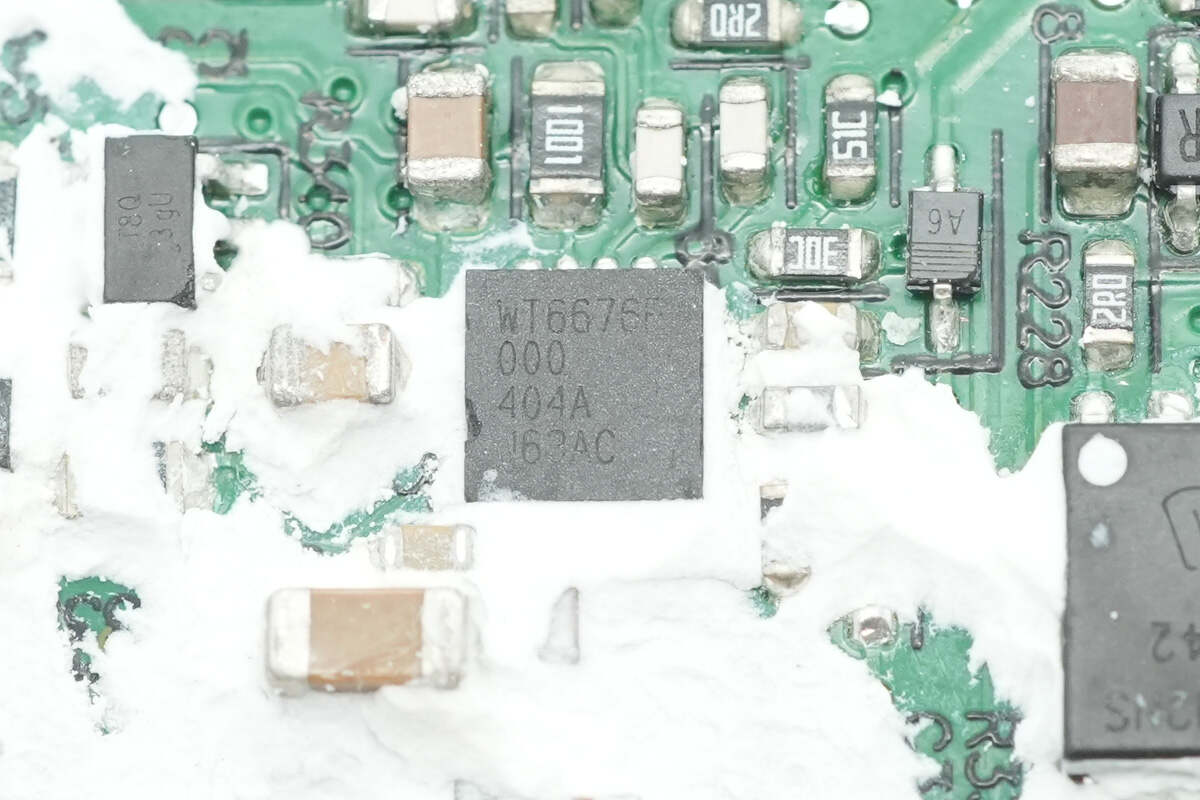
Close-up of the Weltrend WT6676F protocol chip.

Well, those are all components of the Delta 300W Triple USB-C AC/DC Power Adapter.
Summary of ChargerLAB
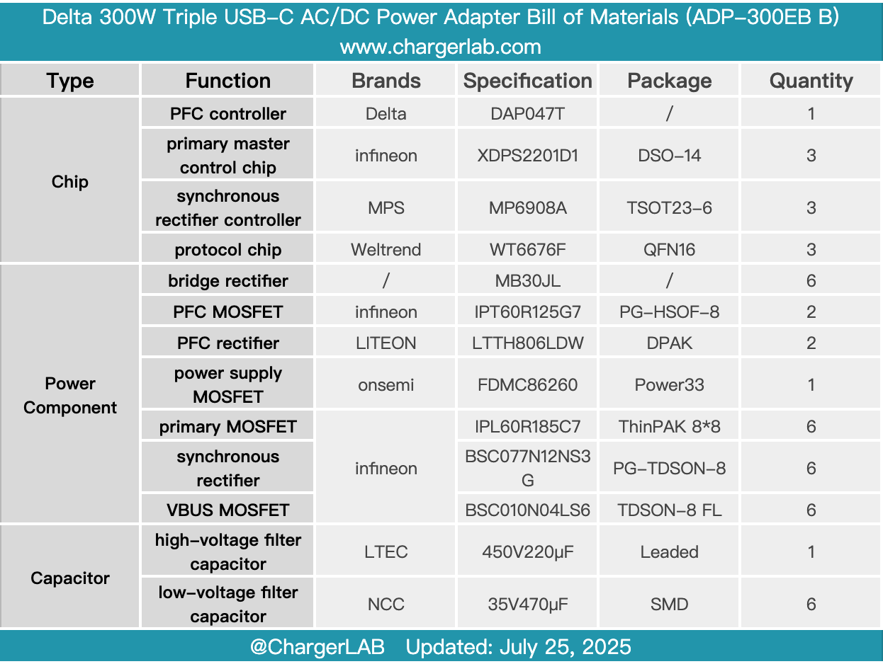
Here is the component list of the Delta 300W Triple USB-C AC/DC Power Adapter for your convenience.
It is equipped with two USB-C cables that support 140W PD 3.1, as well as a USB-C port supporting 100W output, providing a maximum total output power of 300W. This meets fast-charging needs and is suitable for fixed locations such as home offices.
After taking it apart, we found that the PFC circuit uses Delta’s custom DAP047T solution. The three switching power supply circuits all utilize the Infineon XDPS2201D1 paired with the MPS MP6908A synchronous rectifier controller, with key power components mainly sourced from Infineon. Capacitive filtering is handled by LTEC and NCC capacitors. The PCBA module features multiple heat sinks, components reinforced with adhesive, and overall excellent build quality and materials.
Related Articles:
1. Teardown of HONOR 100W GaN Charger for Laptop (HN-200500CP0)
2. Teardown of UGREEN Nexode 65W Charger with Retractable USB-C Cable (X605)
3. Teardown of UGREEN USB-C to DisplayPort 8K Cable (CM556)