Introduction
CUKTECH has recently released the 25 Power Bank SE, featuring high capacity, high output power, and a built-in cable. It comes with a digital display that shows real-time charging wattage and remaining battery level. Together with the built-in USB-C cable, the device offers three outputs in total: two USB-C ports and one USB-A port. It supports Xiaomi’s 120W, 100W PD, as well as PPS, FCP, and other fast-charging protocols. The maximum input power reaches 100W. Below is a closer look at the product’s design.
Product Appearance
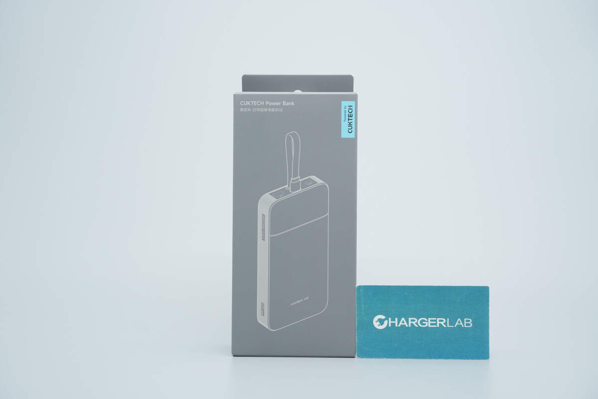
The front of the packaging features the product name along with a line-drawing outline of the device.
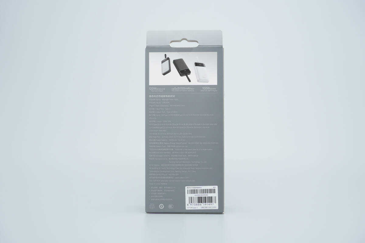
The back of the packaging lists the technical specifications.
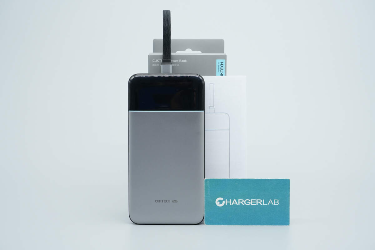
Inside the package, you’ll find the power bank and the user manual.
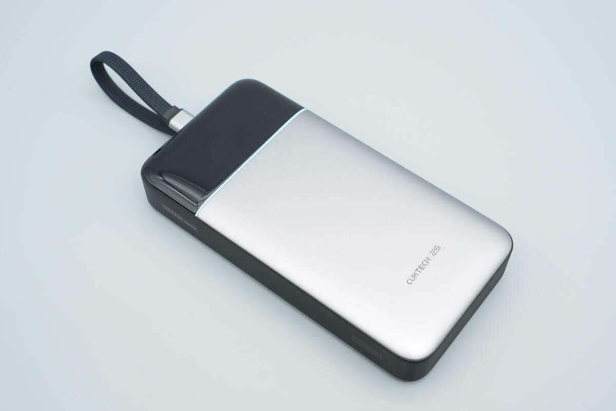
The upper section features a black panel with an integrated digital display, while the lower section is finished in titanium gray.
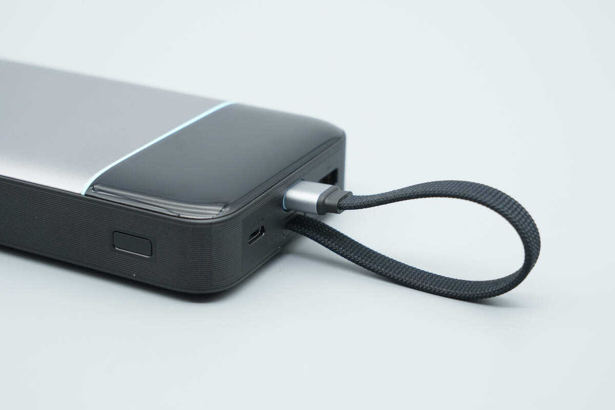
At the top is a braided flat USB-C built-in cable.
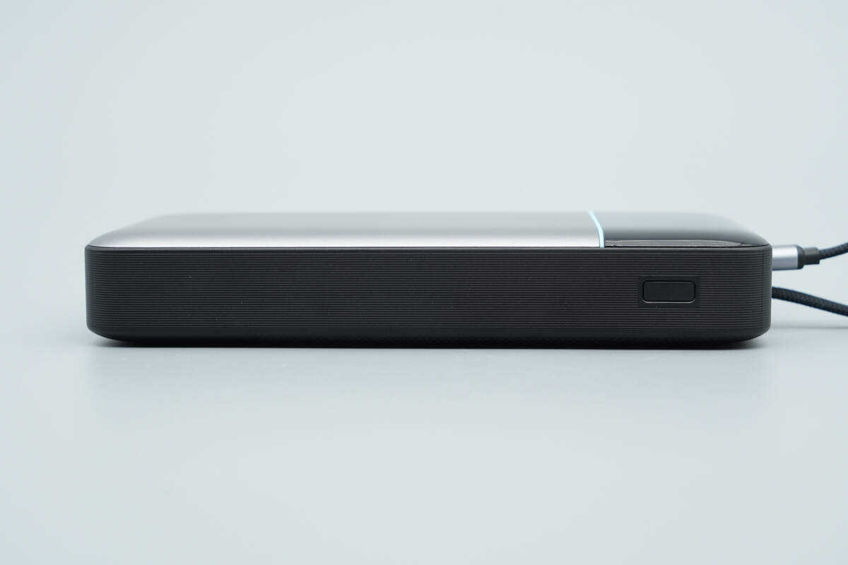
This side features horizontal anti-slip grooves and a power button.

Pressing the power button displays the remaining battery level.
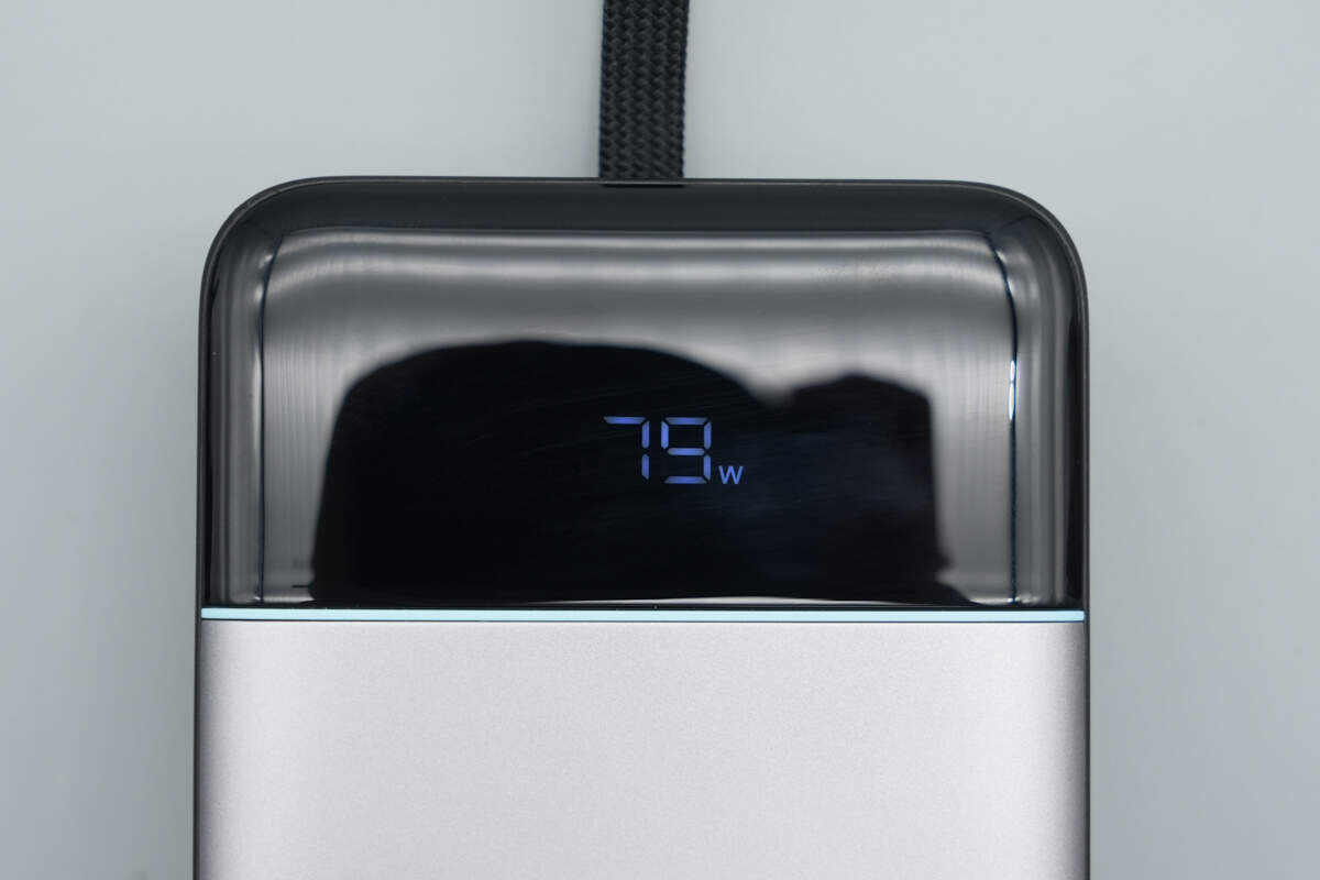
It can also show the real-time charging wattage.
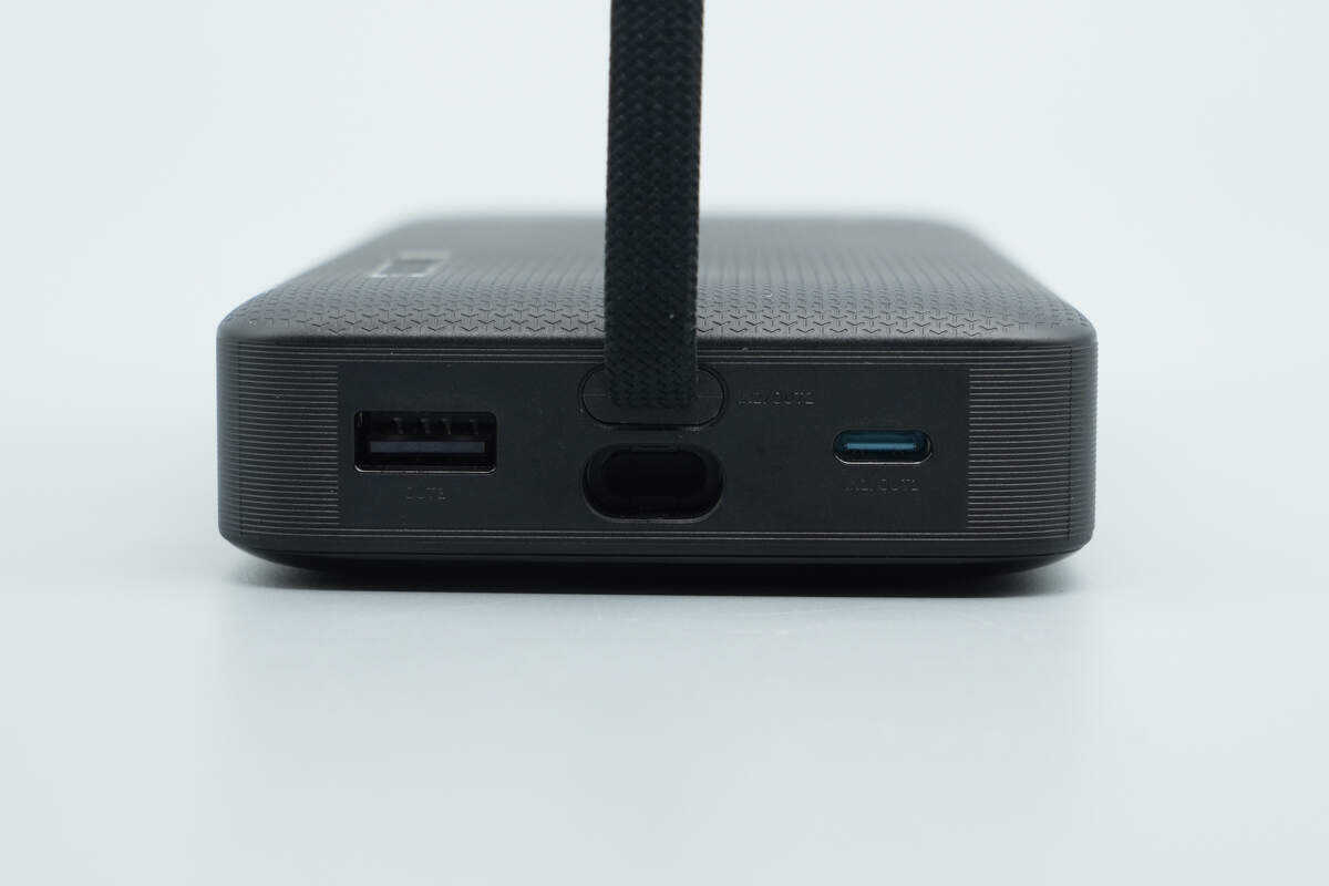
In addition to the built-in cable, the top side also includes one USB-A port and one USB-C port. Beneath the built-in cable is a slot for storing the connector.
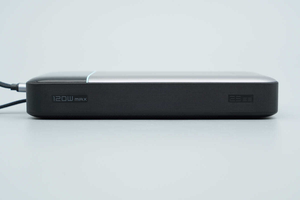
The opposite side also features grooves and is marked with “120W Max” and “25 SE.”
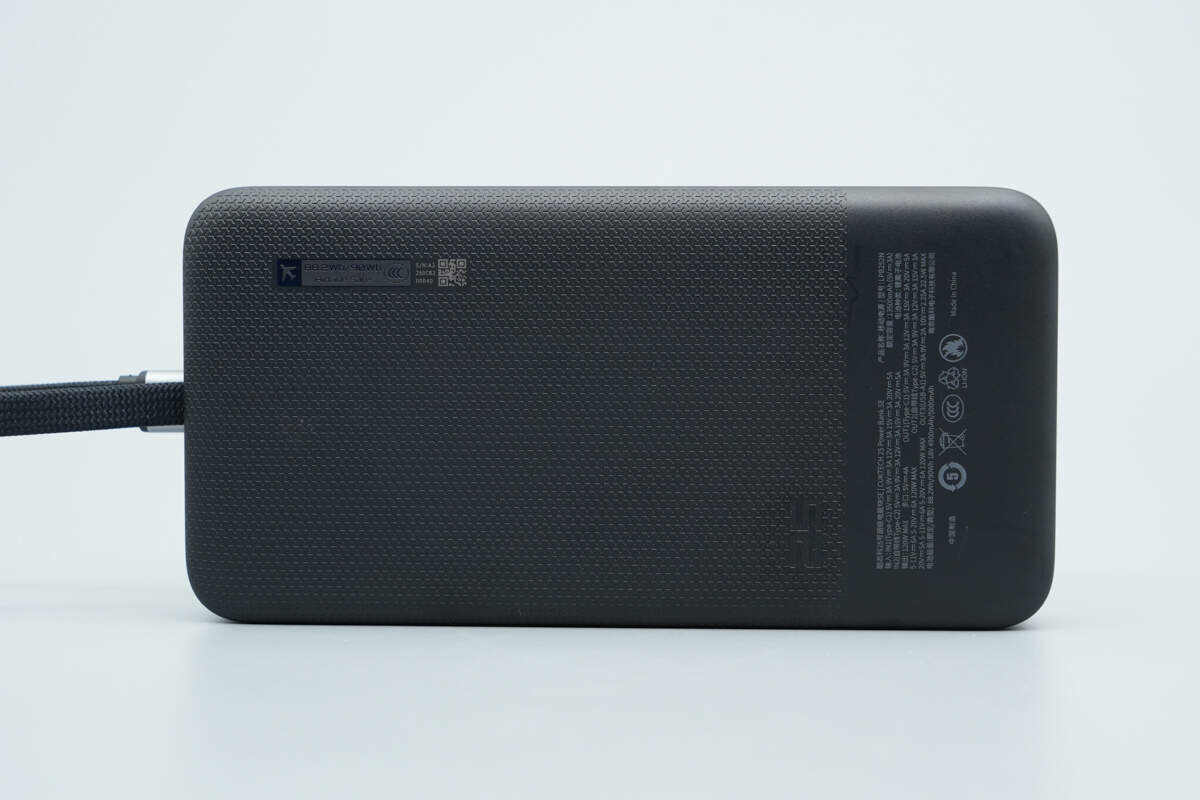
The back has an anti-slip texture and displays the technical specifications.
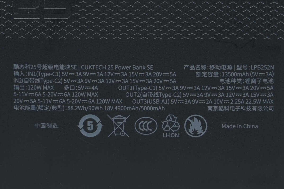
Model: LPB252N
Input Parameters:
IN1 (Type-C1 port): 5V 3A, 9V 3A, 12V 3A, 15V 3A, 20V 5A (up to 100W)
IN2 (Built-in Type-C2 cable): 5V 3A, 9V 3A, 12V 3A, 15V 3A, 20V 5A (up to 100W)
Output Parameters:
Total Output Power: 120W MAX
Simultaneous Multi-Port Output: 5V 4A
OUT1 (Type-C1 port): 5V 3A, 9V 3A, 12V 3A, 15V 3A, 20V 5A, 5–11V 6A, 5–20V 6A (120W MAX)
OUT2 (Built-in Type-C2 cable): 5V 3A, 9V 3A, 12V 3A, 15V 3A, 20V 5A, 5–11V 6A, 5–20V 6A (120W MAX)
OUT3 (USB-A1 port): 5V 3A, 9V 2A, 10V 2.25A (22.5W MAX)
Battery Type: Lithium-ion battery
Battery Energy (Rated/Typical): 88.2Wh / 90Wh, 18V 4900mAh / 5000mAh
Rated Capacity: 13,500mAh (5V/3A)
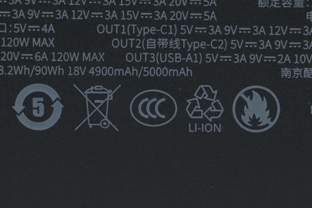
It has obtained CCC certification.
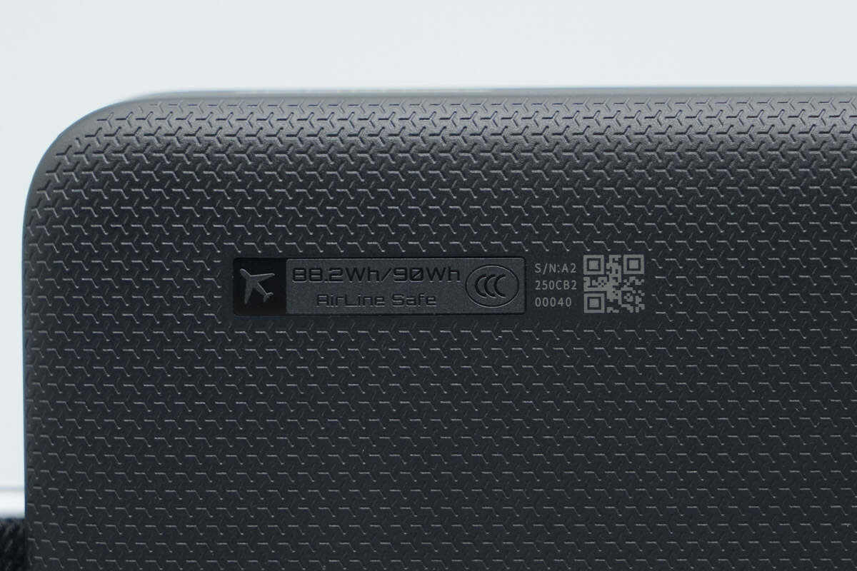
In one corner of the back, the battery energy specification (88.2Wh/90Wh) and the airline-approved symbol are displayed.
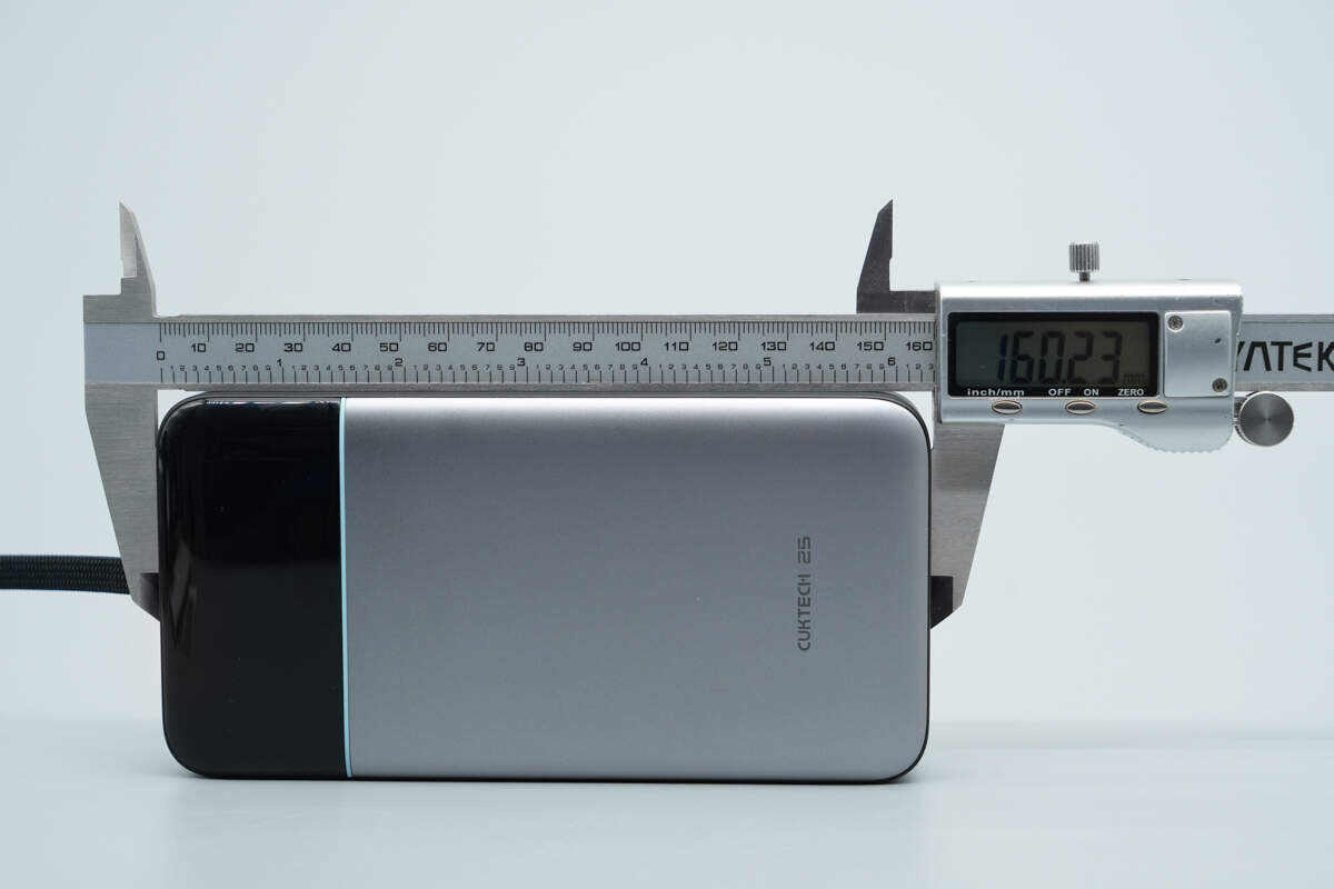
The length of the power bank is about 160.23 mm (6.31 inches).
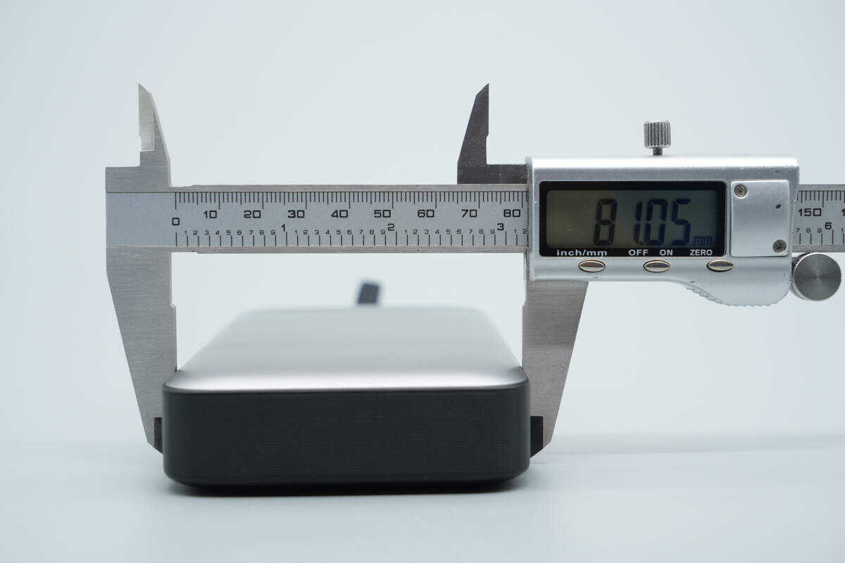
The width is about 81.05 mm (3.19 inches).
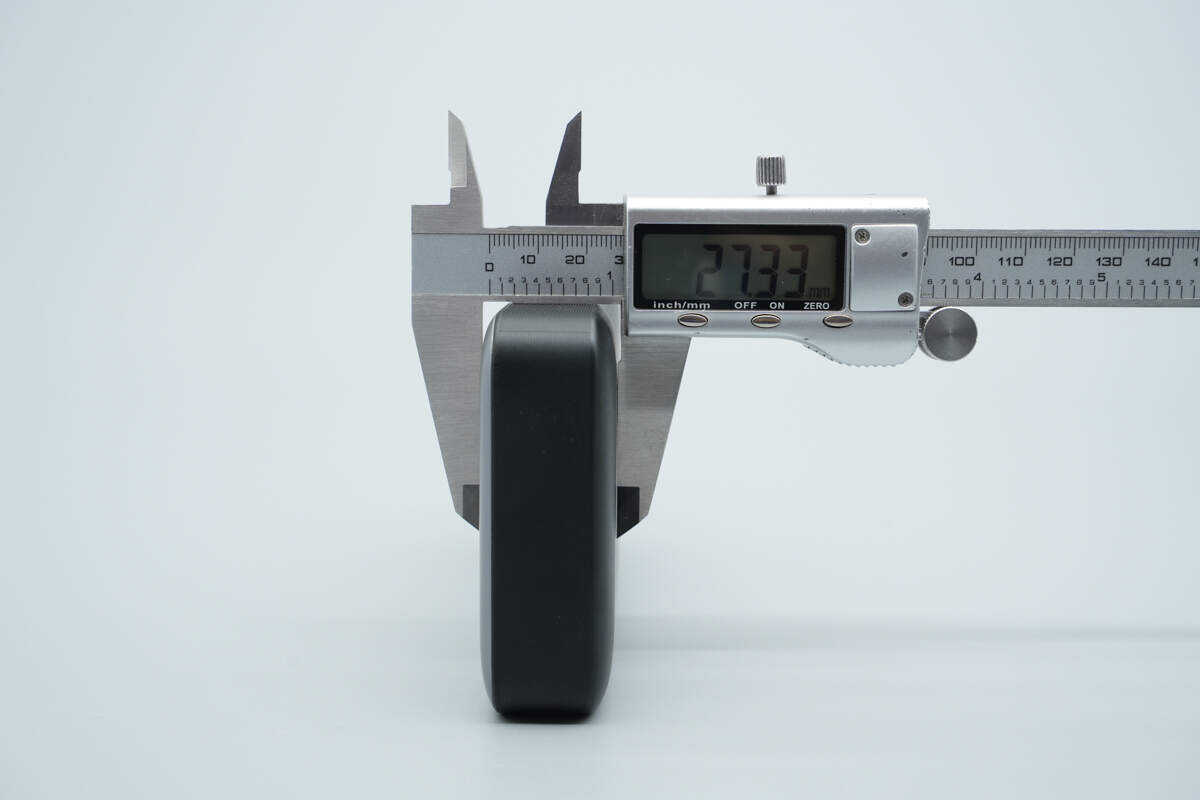
The thickness is about 27.33 mm (1.076 inches).
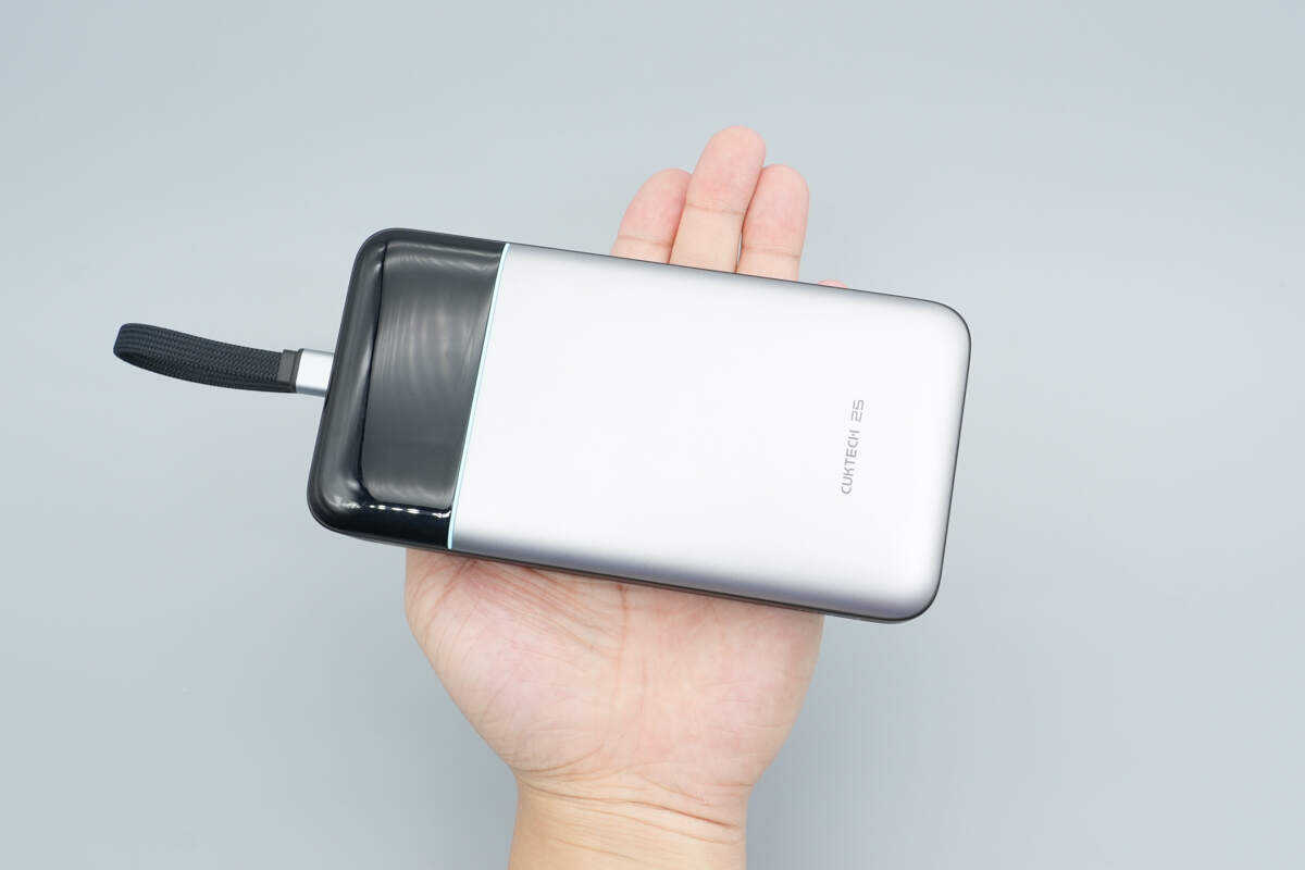
That's how big it is in the hand.
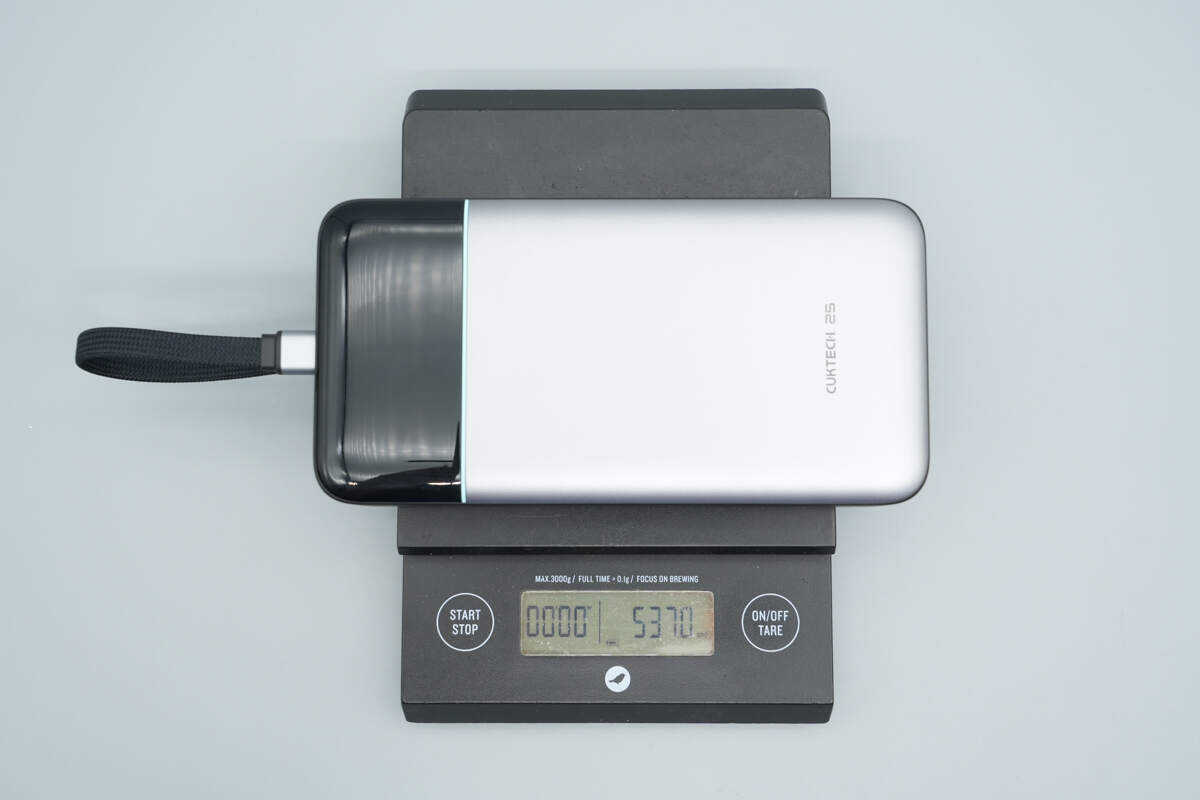
The weight is about 537 g (18.94 oz).
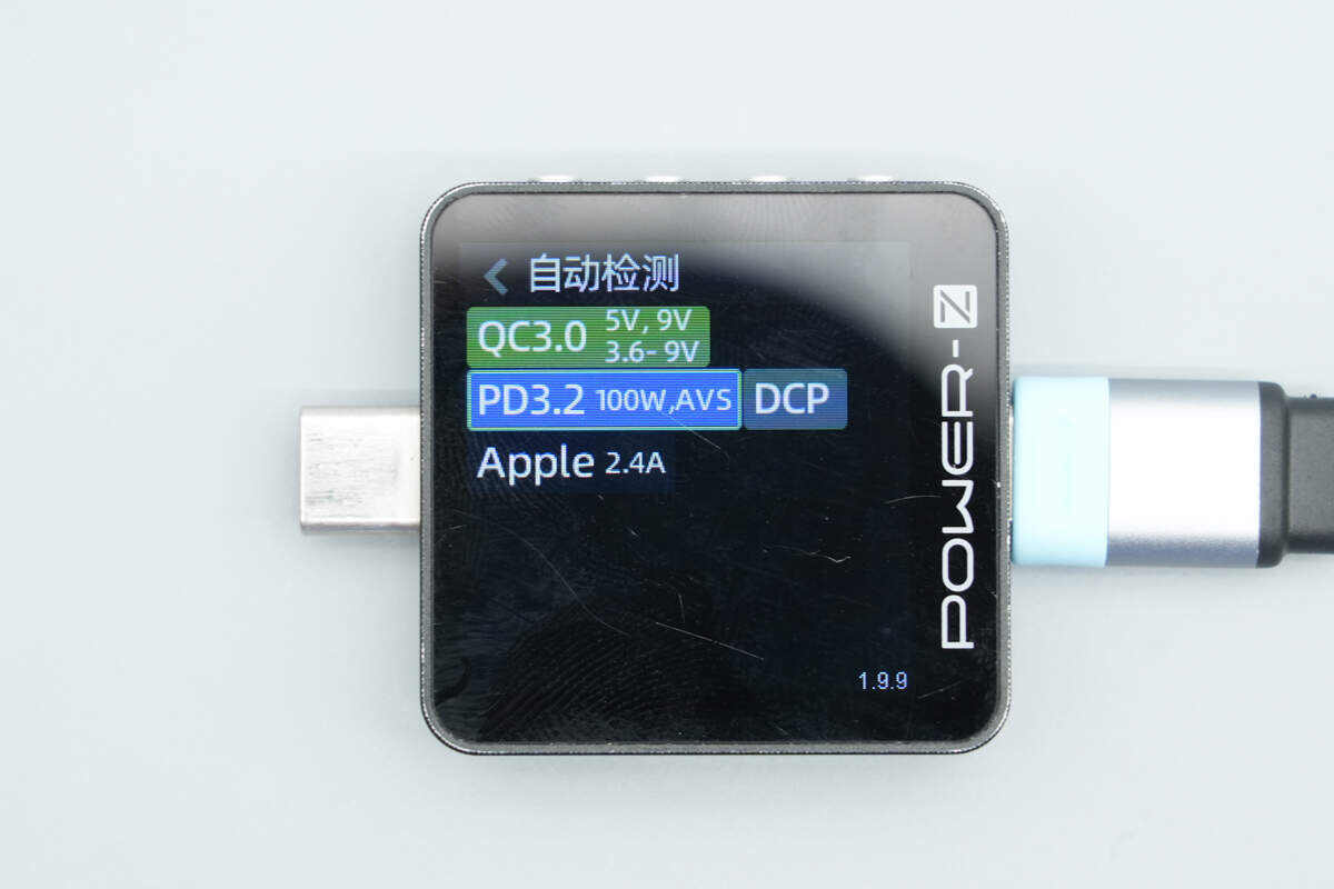
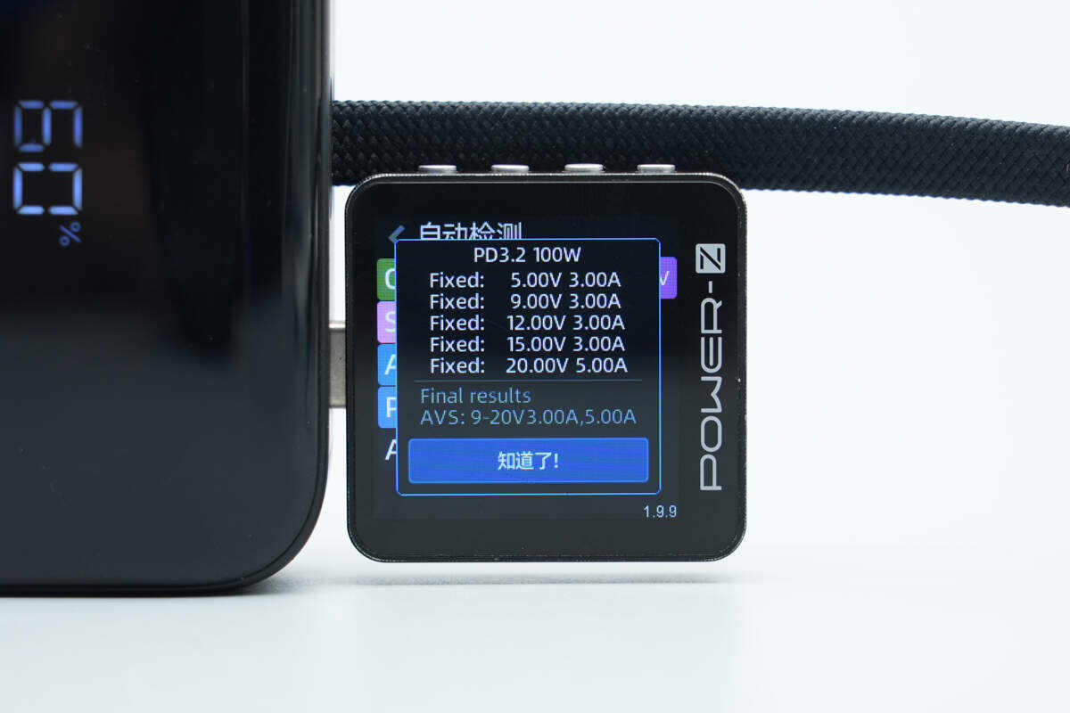
ChargerLAB POWER-Z KM003C shows that the USB-C cable supports PD3.2 AVS, QC3.0, DCP, and Apple 2.4A charging protocols.
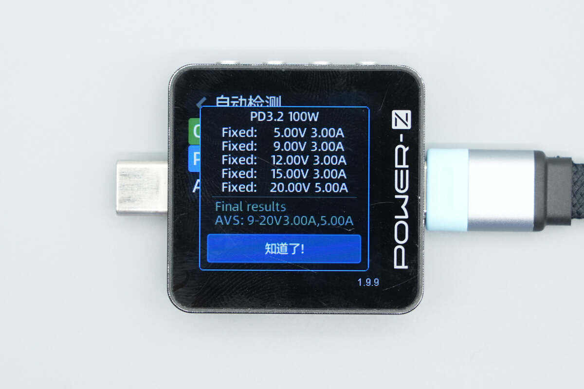
It also features five fixed PDOs: 5V 3A, 9V 3A, 12V 3A, 15V 3A, and 20V 5A, as well as adjustable SPR/AVS voltage ranges of 9–20V 3A and 5A.
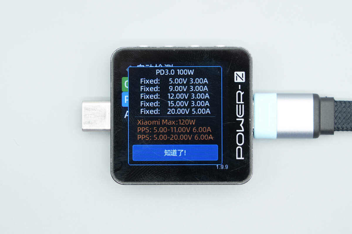
It also supports Xiaomi’s 120W Surge fast charging.
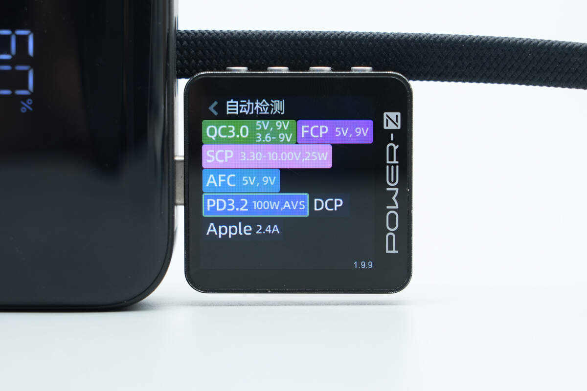
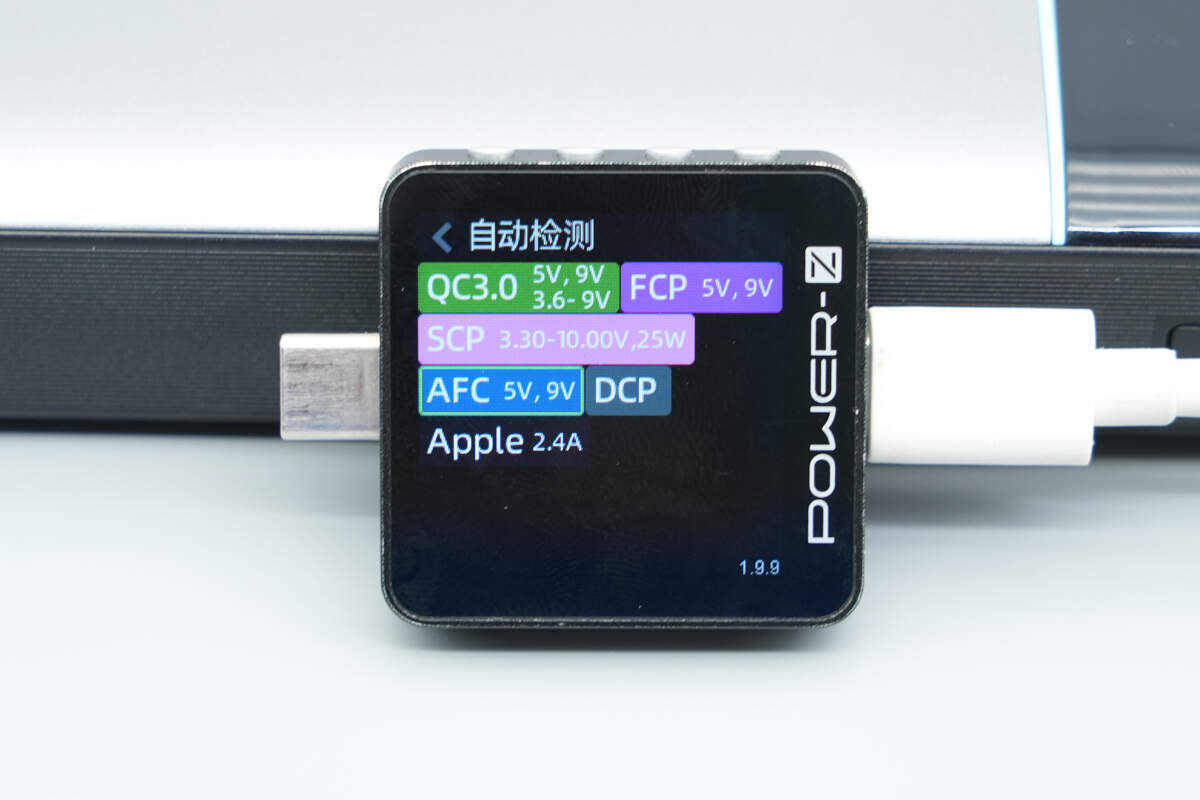
The USB-C port supports PD3.2 AVS, QC3.0, FCP, SCP, AFC, DCP, and Apple 2.4A charging protocols.
It also features five fixed PDOs: 5V3A, 9V3A, 12V3A, 15V3A, and 20V5A, as well as adjustable SPR/AVS voltage ranges of 9–20V 3A and 5A.
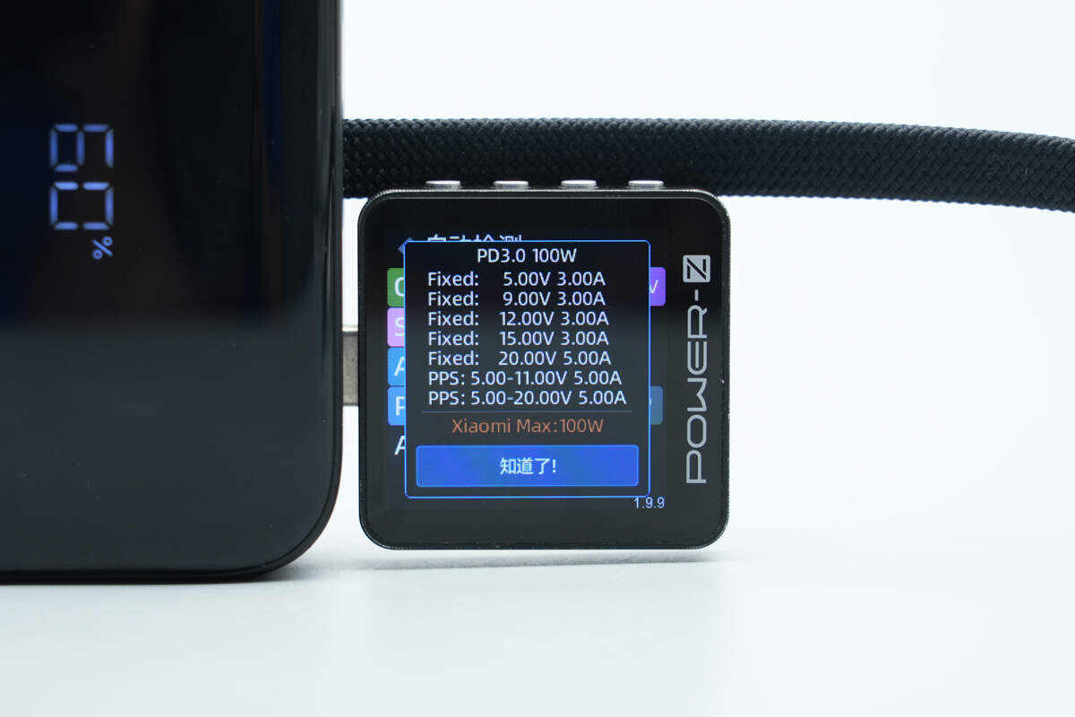
It also supports Xiaomi’s 120W Surge fast charging.
The USB-A port supports QC3.0, FCP, SCP, AFC, DCP, and Apple 2.4A charging protocols.
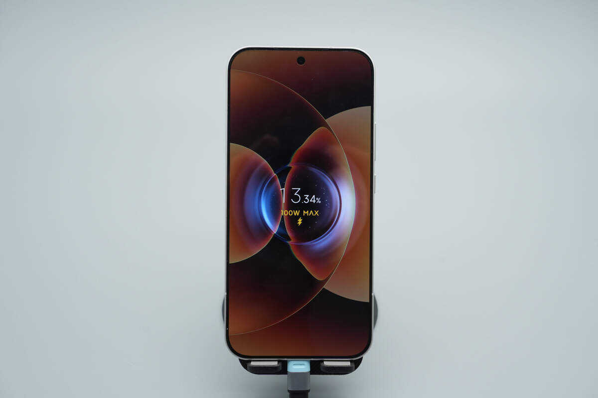
Using the built-in cable to charge the Xiaomi 17 Pro Max, it successfully activated Xiaomi’s 100W Surge fast charging.
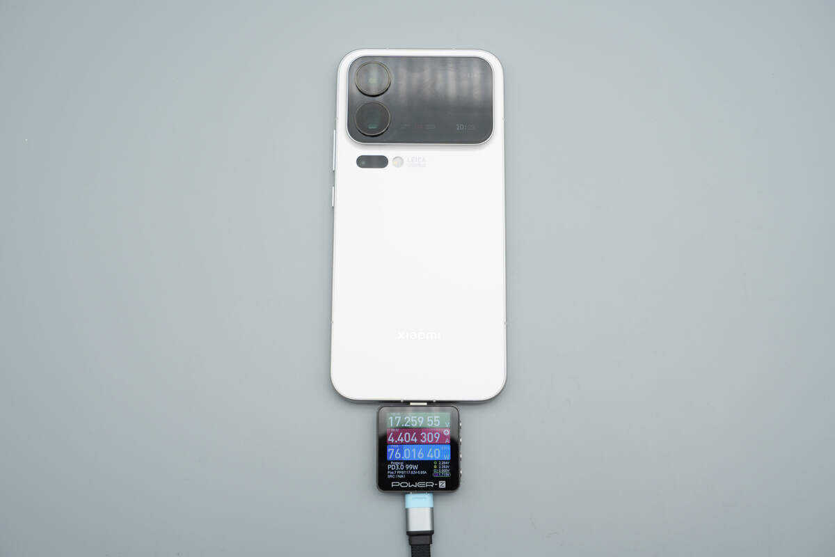
When the charging power stabilized, it was measured at 76W.
Teardown
Next, let's take it apart to see its internal components and structure.
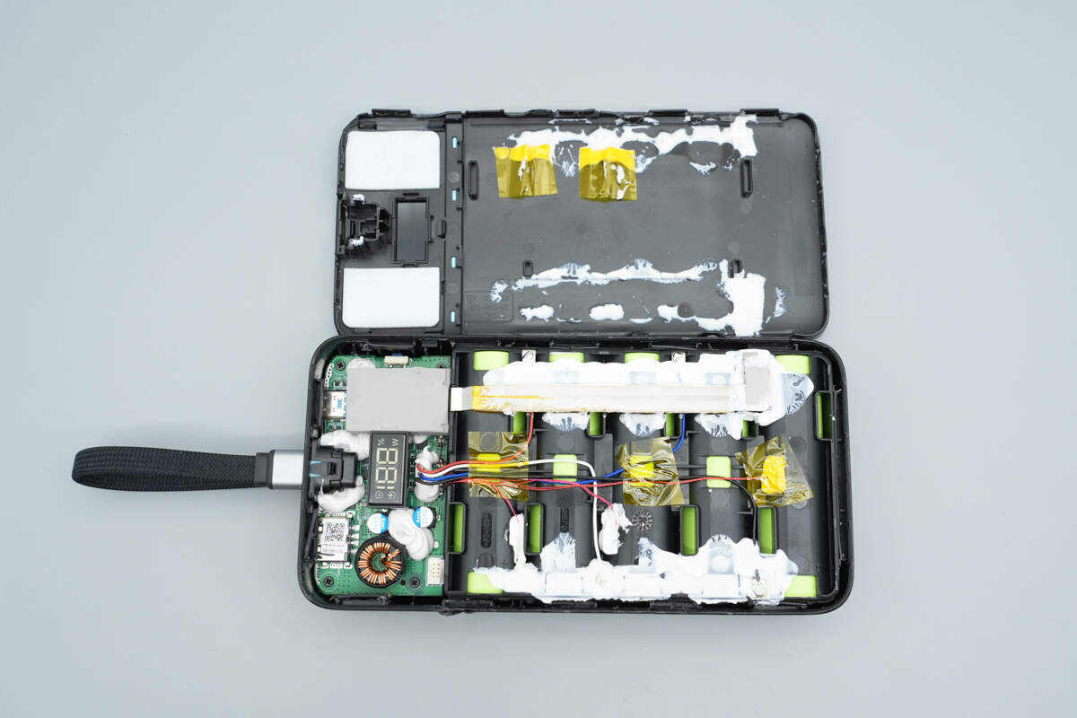
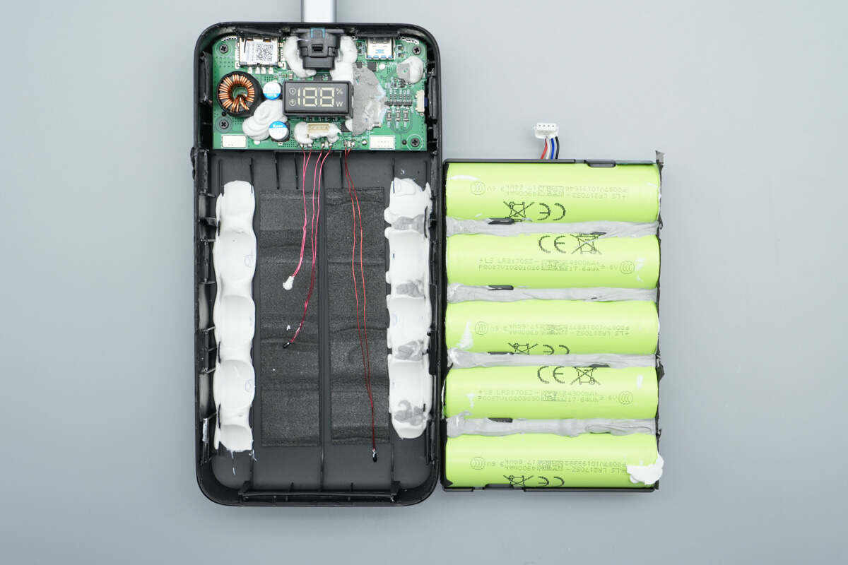
By prying open the cover, the latch is connected and secured with white potting adhesive.
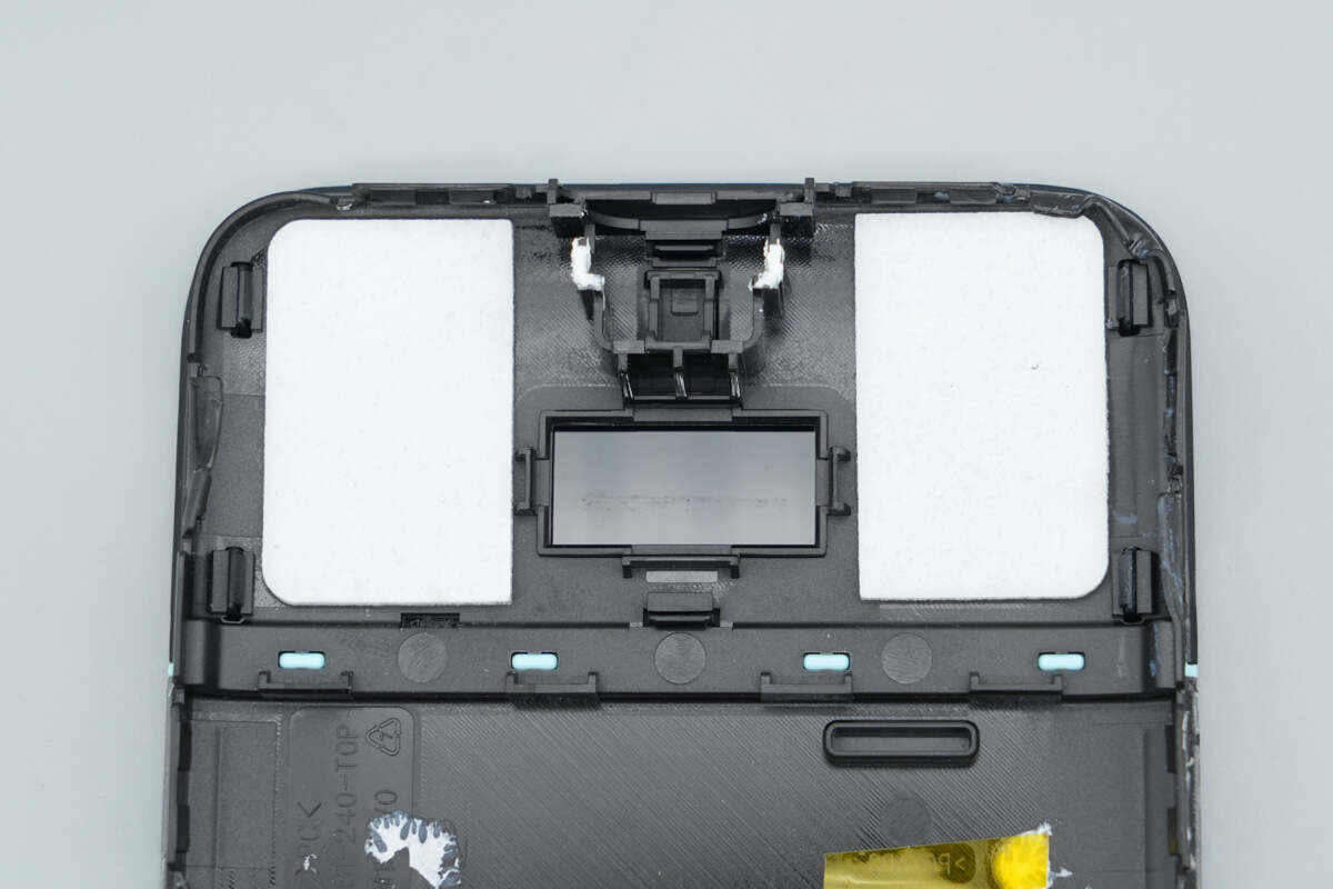
The central section features a semi-transparent window with white cushioning foam attached on both sides.
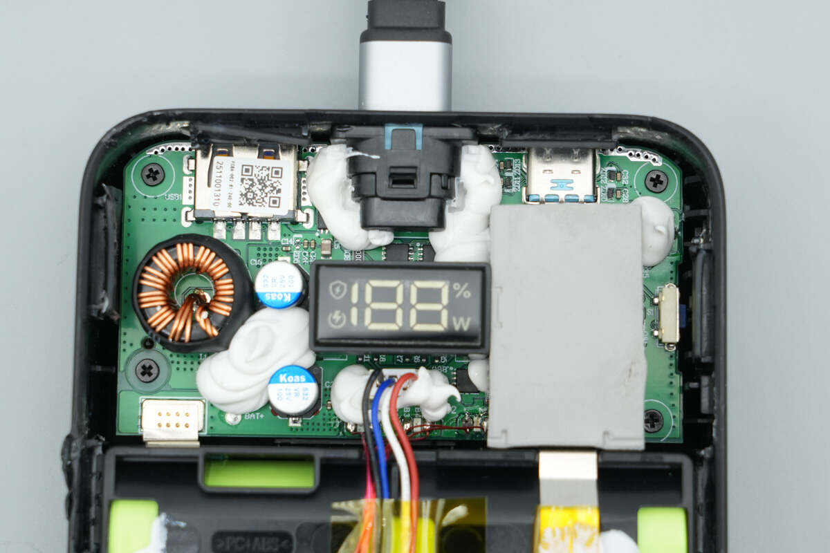
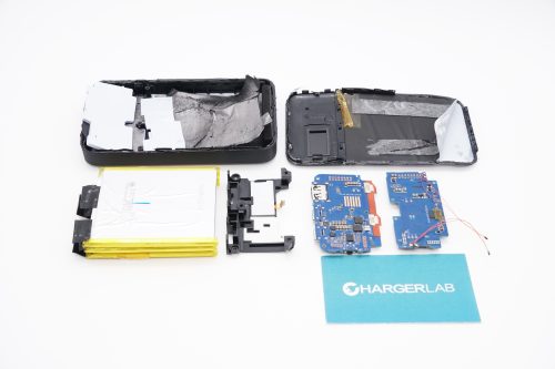
The PCBA module is located in the upper section.
The battery sensing ribbon cable is connected to the PCBA module.

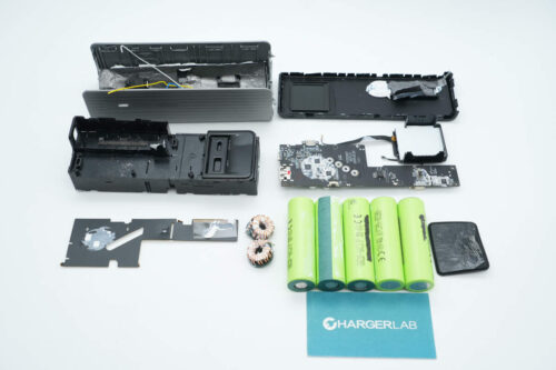
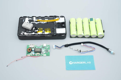
The device contains multiple built-in lithium cells, which are secured by a plastic frame.
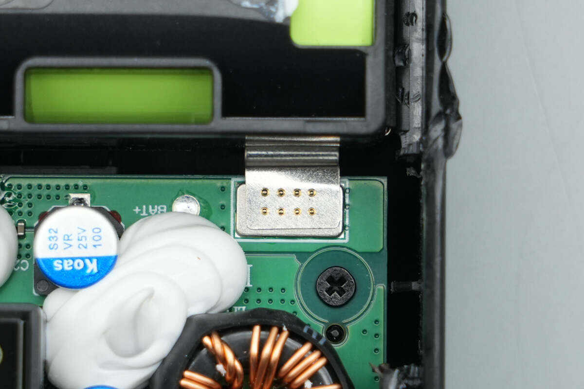
The battery pack is connected to the PCB via nickel strips.
Remove the battery cells.
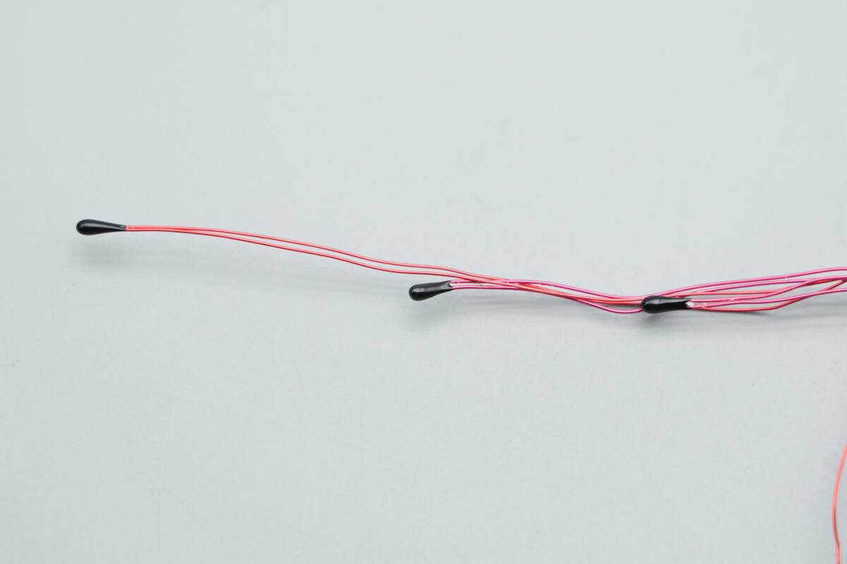
Close-up of the three NTC thermistors.
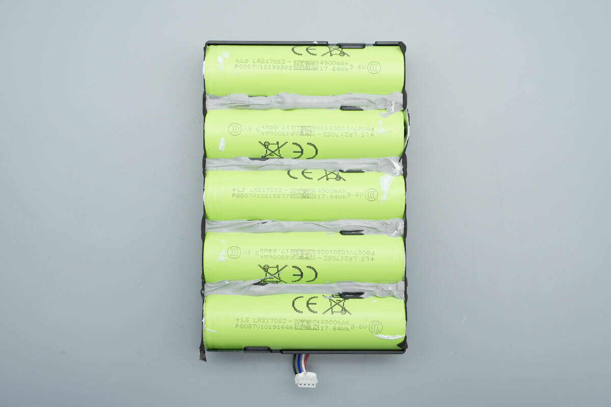
The battery pack consists of five cells, with white adhesive applied between the cells for stabilization.
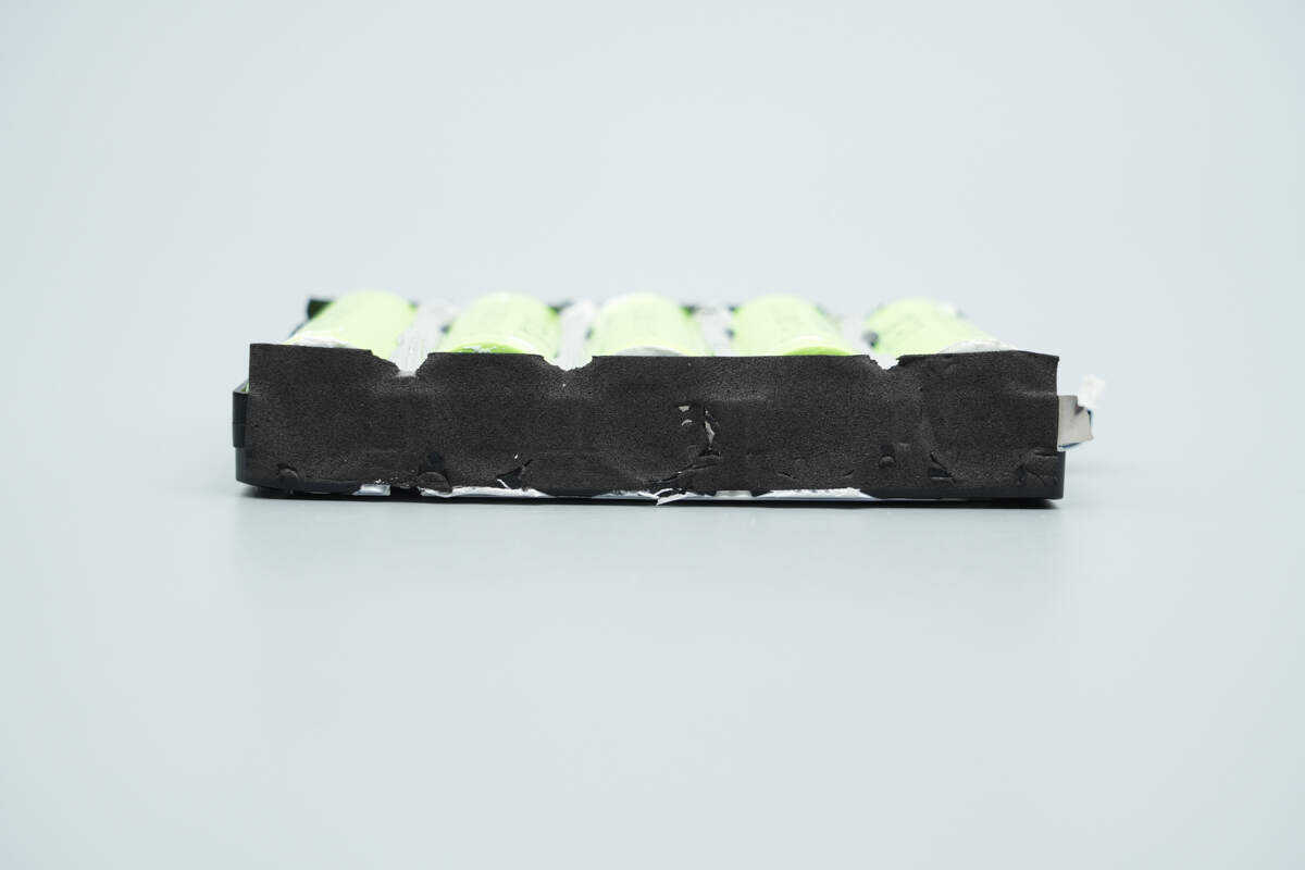
This side is covered with kraft paper.
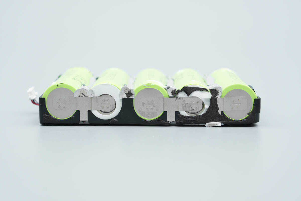
Each cell is connected in series using nickel strips.
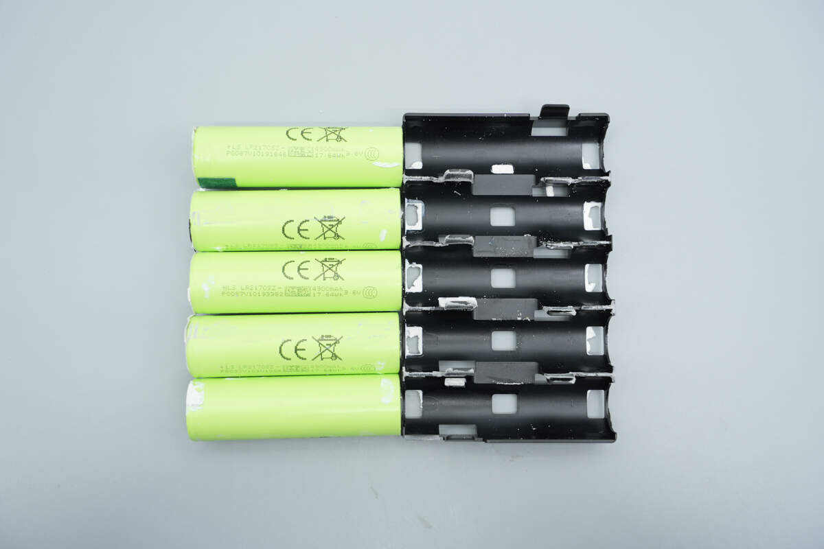
Removed the cells from the plastic frame.
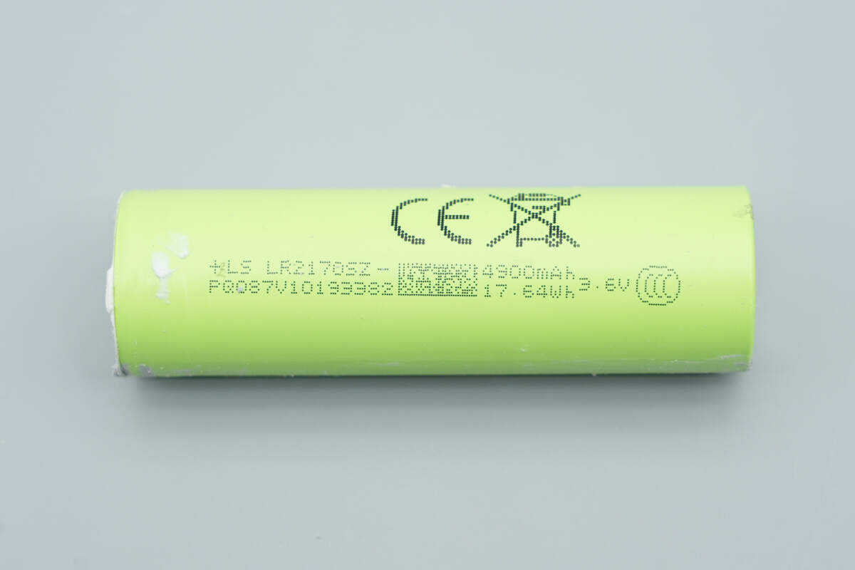
The battery cells are model LR2170SZ, size 21700, manufactured by LS, with a capacity of 4900mAh and a nominal voltage of 3.6V, providing 17.64Wh of energy. They are certified with CCC and CE.
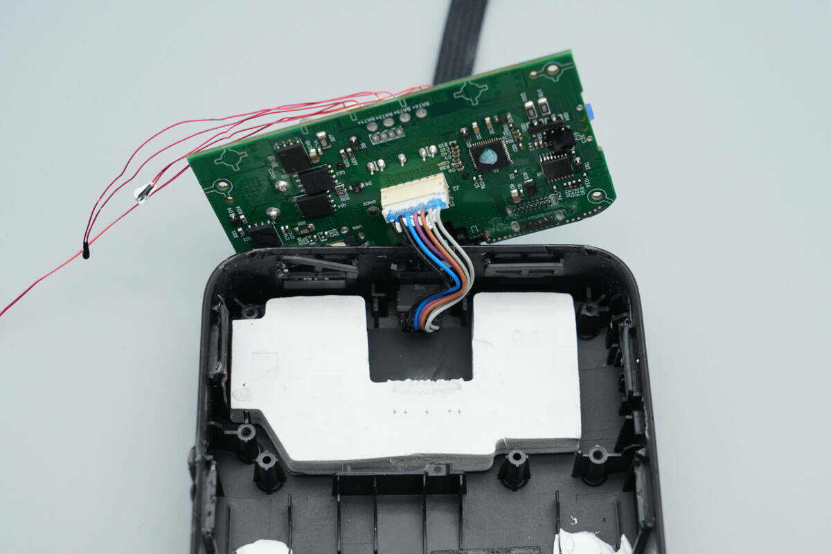
The built-in cable is connected to the PCBA module via a connector.

A white thermal silicone pad is placed beneath the PCBA module.
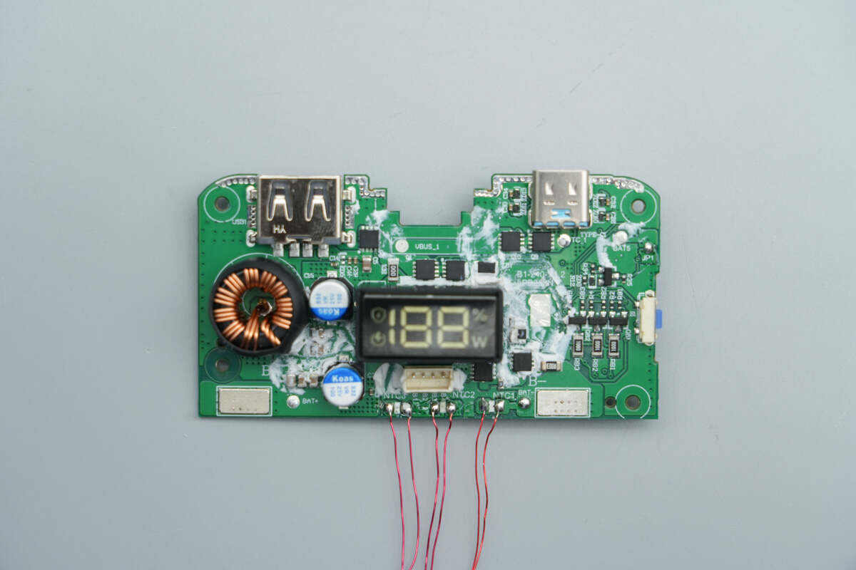
The front side of the PCBA module is soldered with VBUS MOSFETs, battery protection MOSFETs, a buck-boost inductor, solid capacitors, and other components.
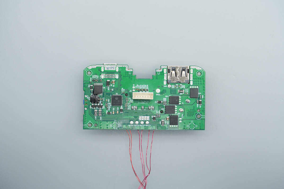
The back side houses the SoC, battery protection chip, synchronous buck-boost MOSFETs, and other components.
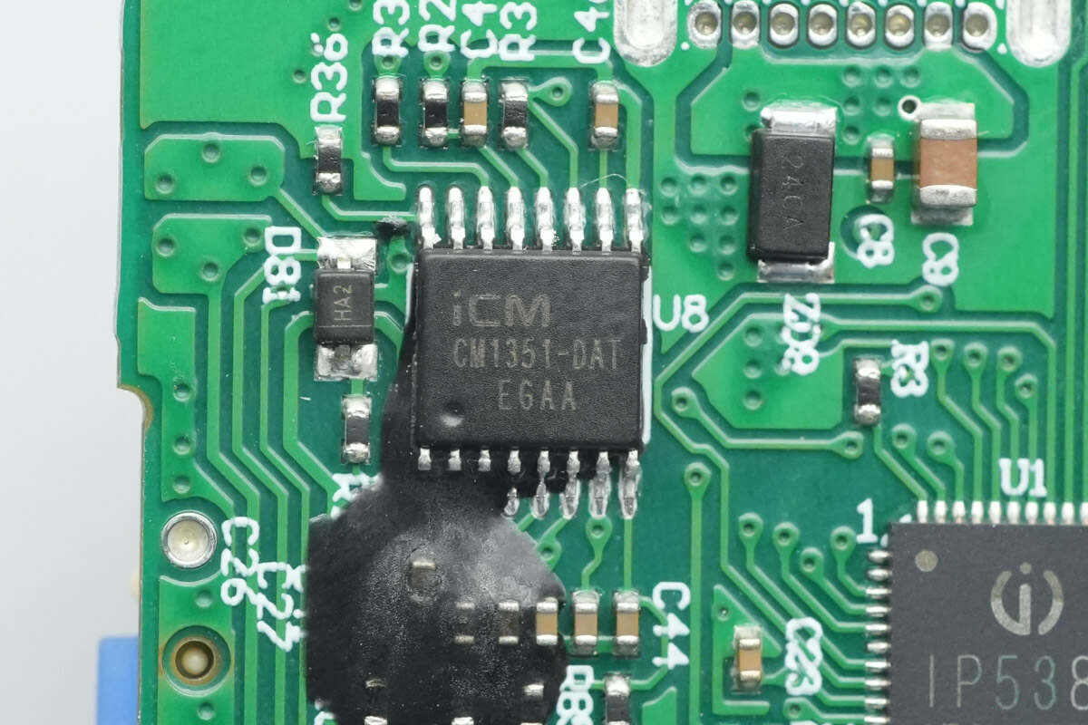
The battery protection chip is the iCM CM1351, specifically designed for 5-series lithium-ion or lithium iron phosphate batteries. It integrates high-precision voltage and current detection circuits. By monitoring each cell’s voltage, charge/discharge current, and temperature, it provides protections including overcharge, overdischarge, cell balancing, disconnection, low-voltage charge inhibition, overcurrent during discharge, short circuit, overcurrent during charge, and over-temperature. The discharge overcurrent protection delay is adjustable via an external capacitor, while all other protection delays are built-in.
The iCM CM1351 also features an internal cell-balancing function. Even without external resistors or MOSFETs, the chip can balance the cells through its internal balancing circuit, ensuring consistency across the battery pack.
The iCM CM1351 offers 15 mV overcharge protection accuracy for individual cells, supports three-level discharge overcurrent protection, and includes charge overcurrent protection. It also provides protection for cell wiring disconnection and NTC thermistor disconnection, delivering comprehensive safety for multi-series lithium battery packs.
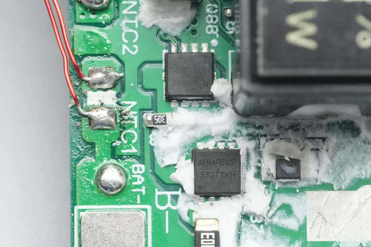
The two battery protection MOSFETs are from ALLEPIC, model AER4051CP. They are NMOS devices with a voltage rating of 40 V and an on-resistance of 6 mΩ, packaged in PDFN3030.
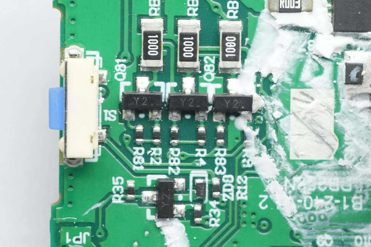
The battery pack balancing circuit consists of balancing MOSFETs and balancing resistors.

The SoC is the Injoinic IP5385, the industry’s first mobile power synchronous buck-boost SoC with integrated UFCS fast-charge fusion. The chip integrates a fast-charging protocol controller, an MCU, and a synchronous buck-boost controller. It supports 2–4 series lithium-ion or lithium iron phosphate batteries and, with external MOSFETs and an inductor, can form a 65W bidirectional fast-charging power bank.
The IP5385 supports two USB-A output ports, one bidirectional USB-C port, and either a Lightning input or USB-C input/output. Any of these ports supports fast charging. The chip is compatible with UFCS fast charge, PD 3.0, PPS, Huawei SCP, FCP, and other fast-charging protocols.
Internally, the IP5385 features a bidirectional synchronous buck-boost driver and an integrated charge pump, supporting high-performance NMOS for switching and path management. When combined with inductors, synchronous MOSFETs, and the corresponding interface path management MOSFETs, it can form a complete multi-interface, 2–4 series battery high-power fast-charging power bank. It supports 65W charge and discharge power, suitable for power banks, energy storage devices, portable electronics, and electric tools.
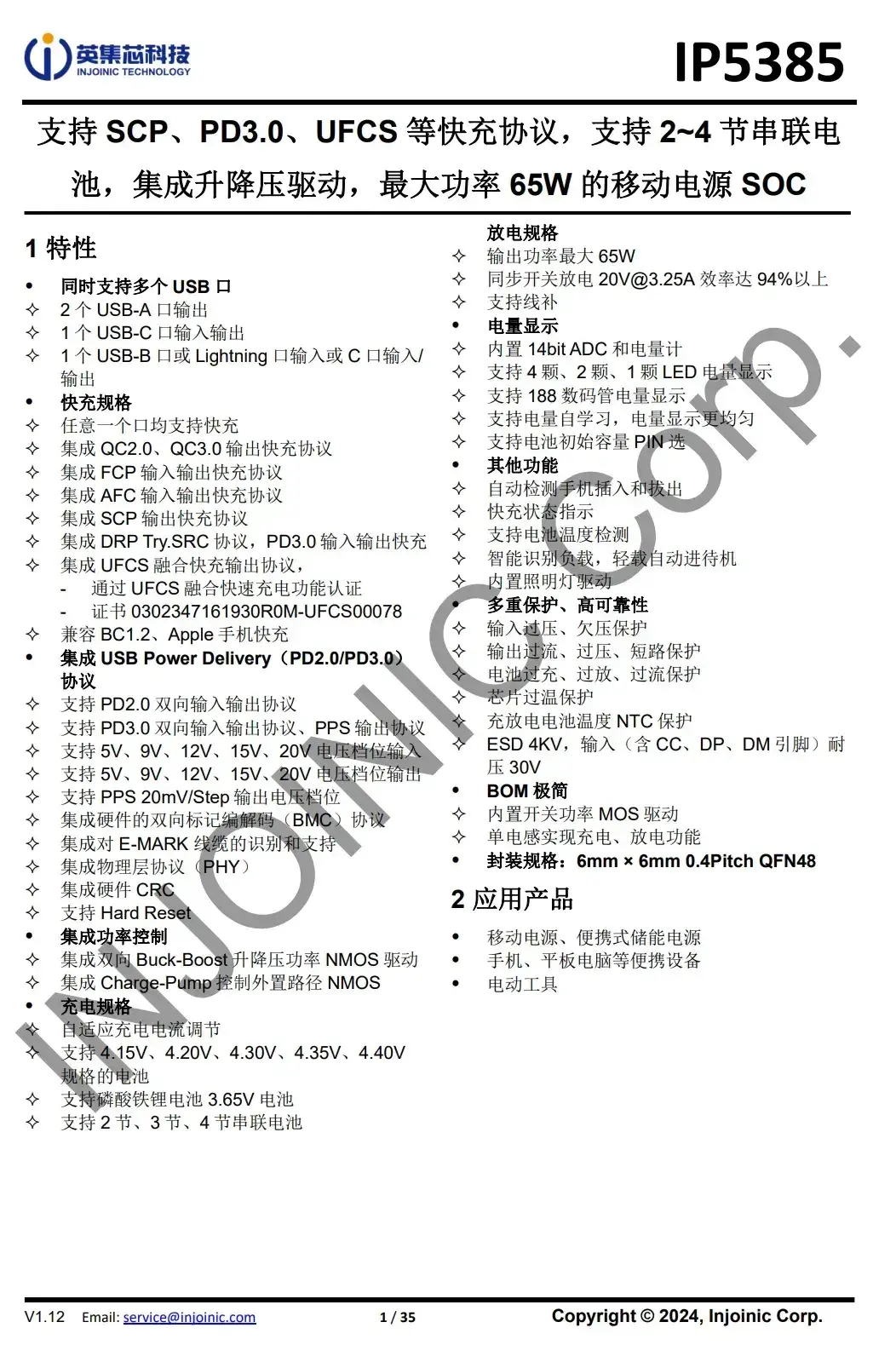
Here is the information about Injoinic IP5385.
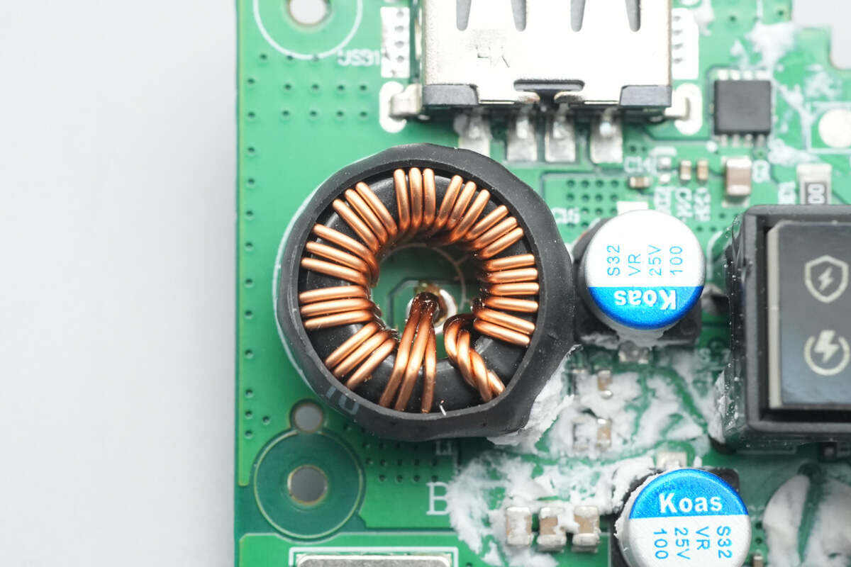
The buck-boost inductor paired with it is insulated with a heat-shrink tube.
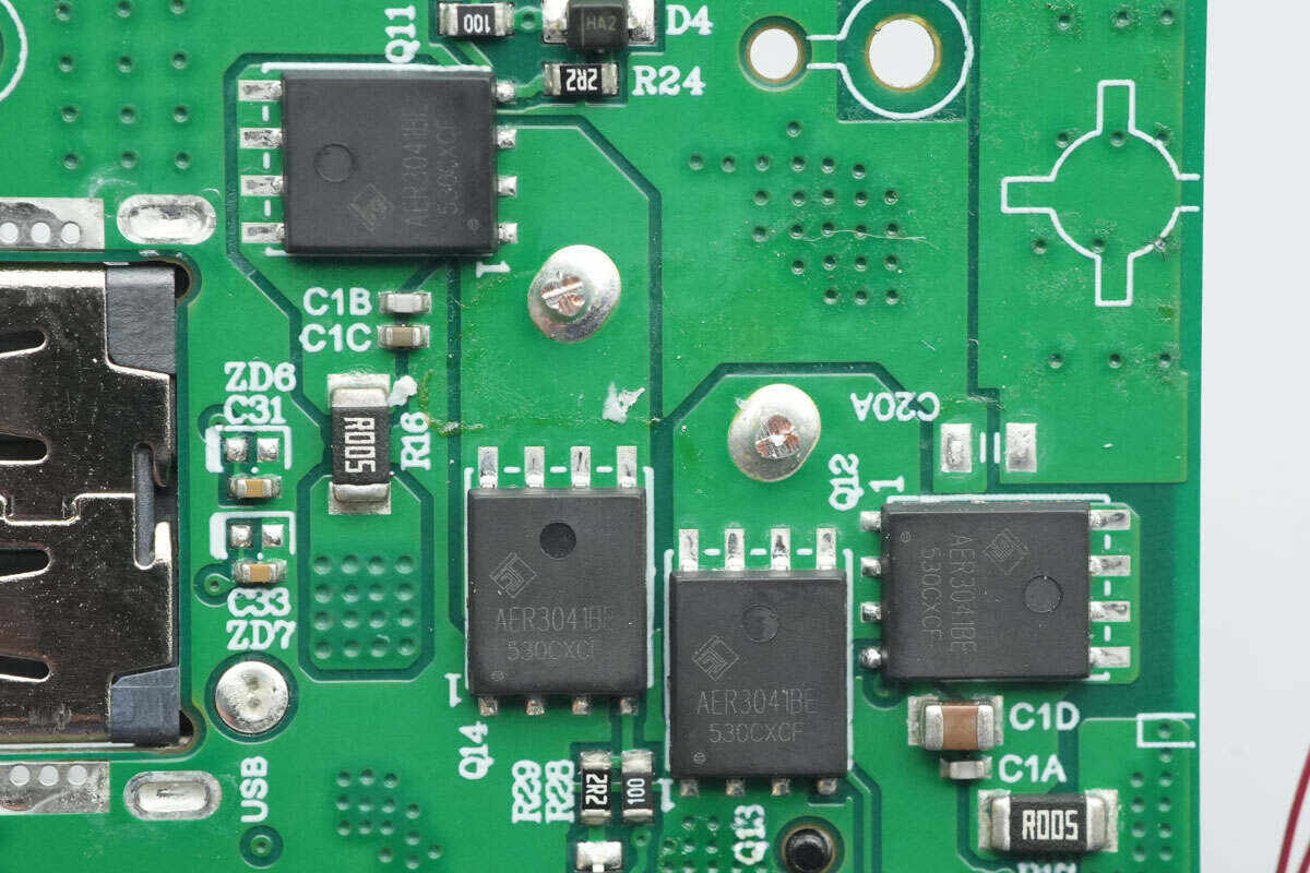
The four synchronous buck-boost MOSFETs are from ALLEPIC, model AER3041BE. They are NMOS devices with a voltage rating of 30 V and an on-resistance of 6 mΩ, packaged in PDFN5060.
The two VBUS MOSFETs controlling the USB-C port are from ALLEPIC, model AET3061AP. They are NMOS devices with a voltage rating of 30 V and an on-resistance of 6 mΩ, packaged in PDFN3030.
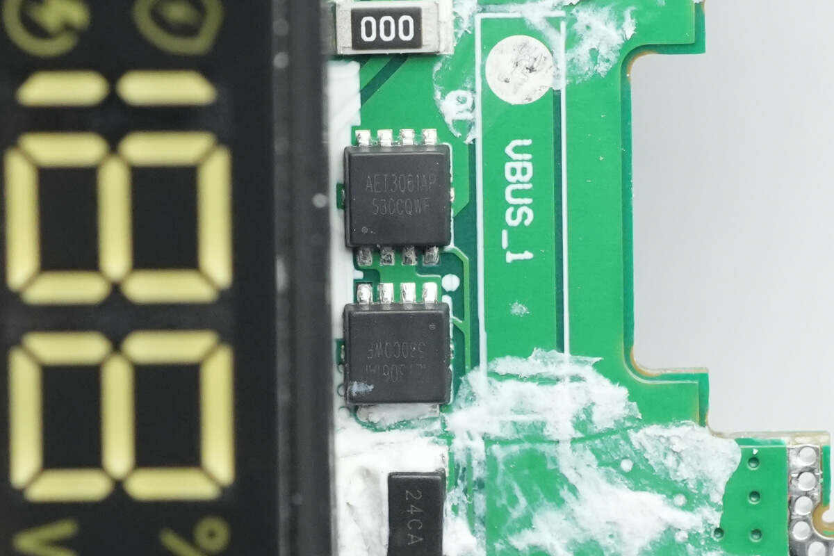
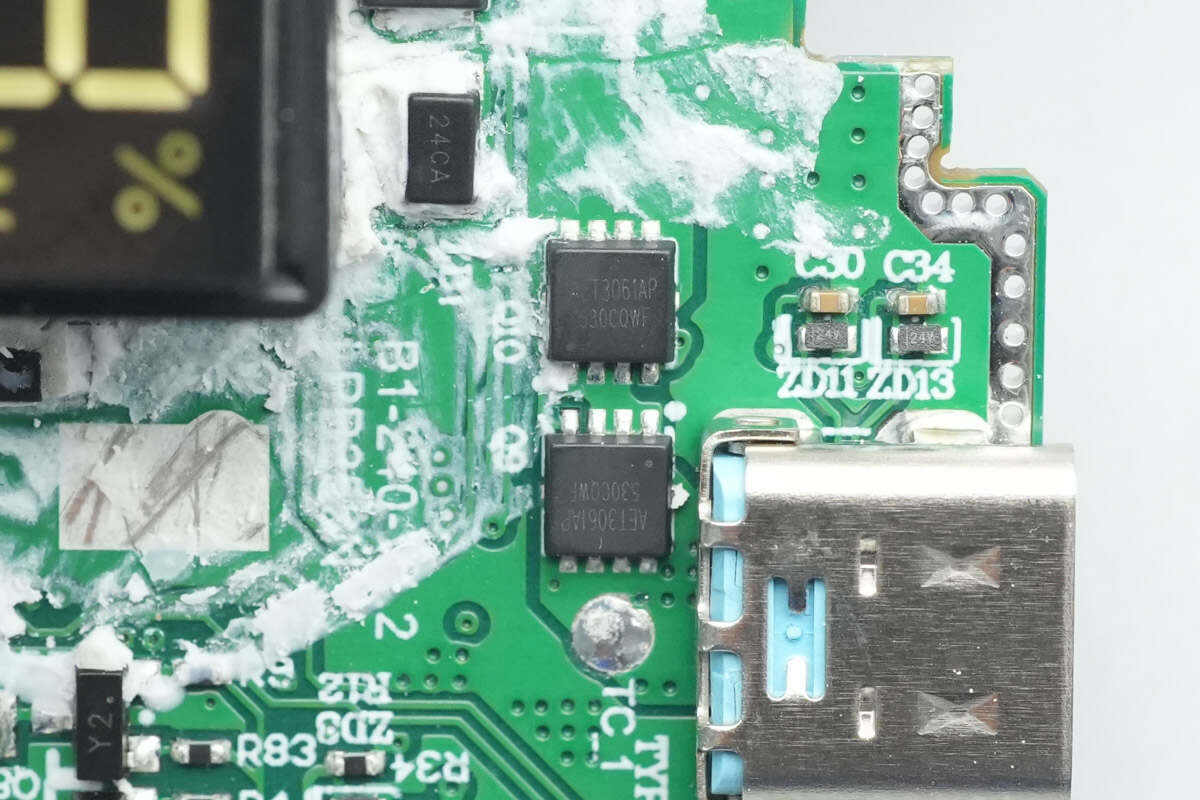
The two VBUS MOSFETs for the built-in USB-C cable are also ALLEPIC AET3061AP devices.
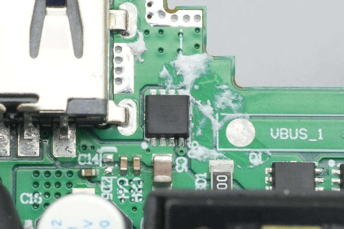
The VBUS MOSFET for the USB-A port is also an ALLEPIC AET3061AP.
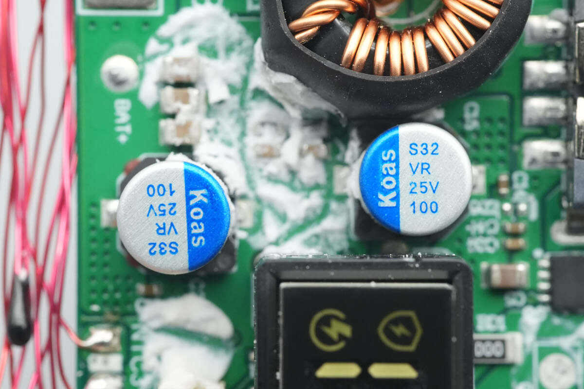
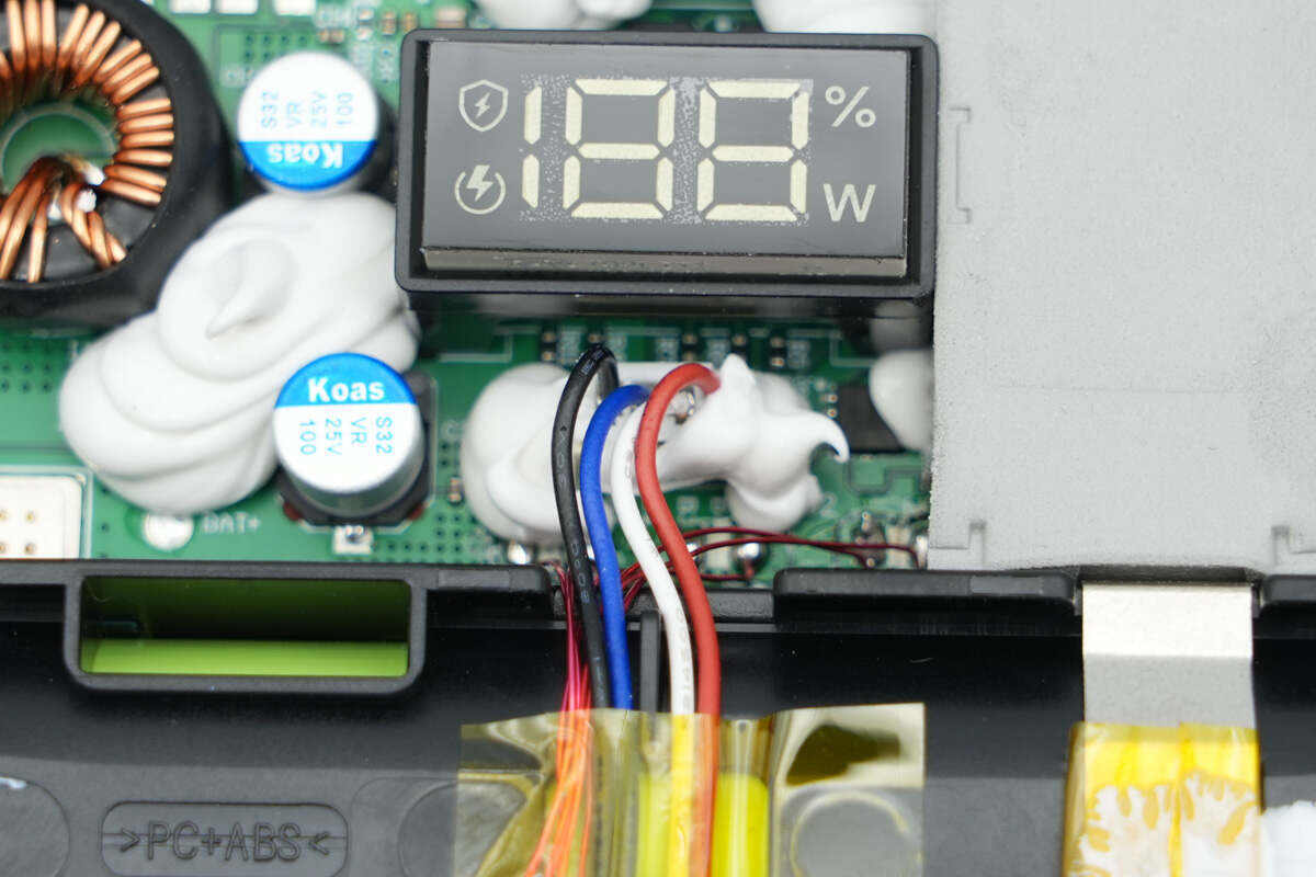
The two solid capacitors are from Koshin, with a specification of 25V 100μF.
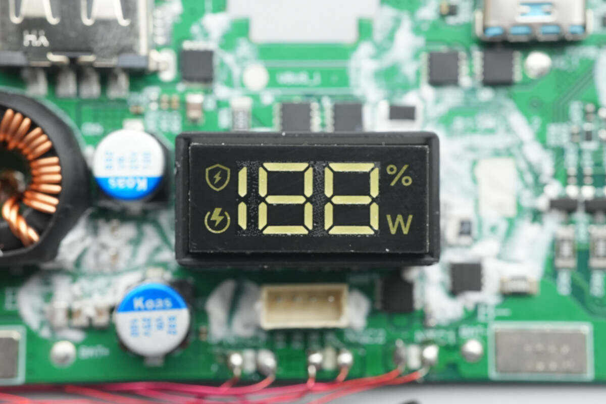
Close-up of the digital display.

Well, those are all components of the CUKTECH 25 Power Bank SE.
Summary of ChargerLAB

Here is the component list of the CUKTECH 25 Power Bank SE for your convenience.
The front is equipped with a digital display, which shows the remaining battery level and output power. It comes with a braided USB-C cable and one USB-C and one USB-A port. The device supports PD3.2, PPS, and other protocols, and is also compatible with Xiaomi’s proprietary 120W fast charging.
After taking it apart, we found that the battery pack consists of 5 LS cells, each with a capacity of 4900mAh and an energy rating of 17.64Wh. The main control chip is the Injoinic IP5385, a highly integrated SoC that combines a fast-charging protocol controller, an MCU, and a synchronous buck-boost controller. The battery protection chip used is the iCM CM1351. Both the battery protection MOSFETs and synchronous buck-boost MOSFETs are sourced from ALLEPIC, with filtering provided by two Koshin solid capacitors. The materials used are solid and reliable.
Related Articles:
1. Teardown of ASUS Adol 140W GaN Quick Charger (AC140-020A)
2. Teardown of MIIIW 140W GaN Charger CA514 Pro (iCA1404)
3. Teardown of IM Motors 50W In-Car Pre-installed Wireless Charging Module