Introduction
CUKTECH has recently launched the 15 Power Bank Air, continuing its signature family design while introducing several notable upgrades. It features a next-generation carbon-silicon anode battery from LS, delivering a large 15,000mAh capacity in a body just 2.1 cm thick.
The power bank is equipped with a high-definition TFT screen, capable of displaying power output per port, total output power, remaining battery level, estimated usage time, customizable screen brightness, and individual port control. It supports ADC 2.0 and is compatible with UFCS, PD, QC, and Xiaomi’s proprietary 90W fast-charging protocol.
Let’s take a closer look at the design details of this impressive new release from CUKTECH.
Product Appearance
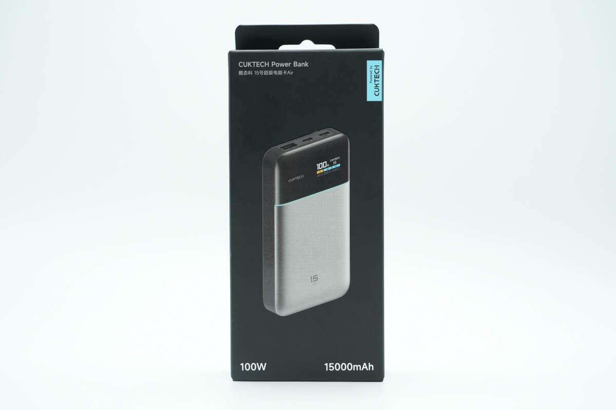
The front of the packaging box is printed with the product name, design, 100W, 15000mAh, and Powered by CUKTECH.
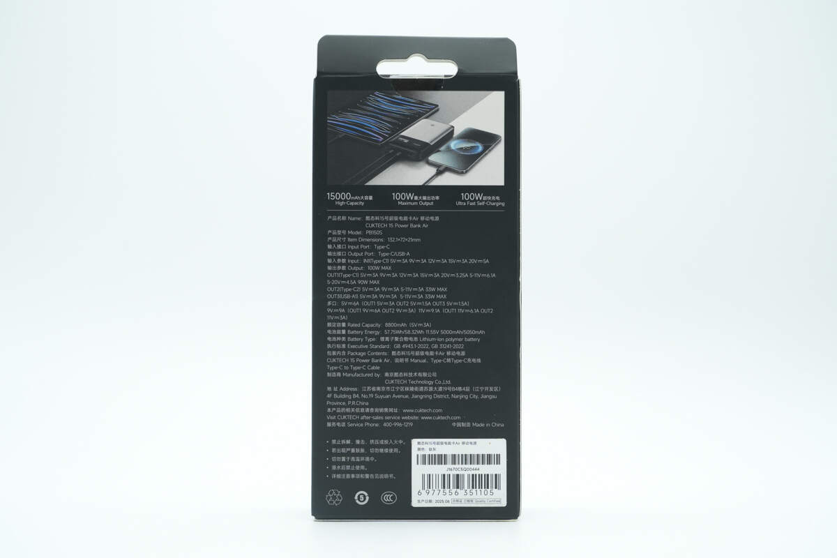
The back features application scenarios along with spec info.
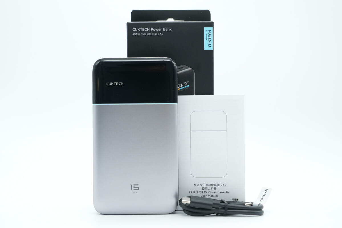
The packaging contains the power bank, cable, and some documents.
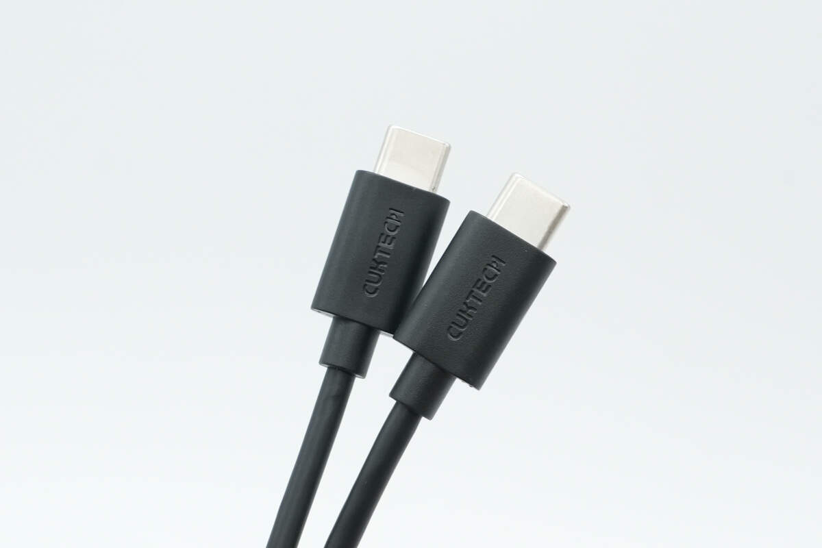
CUKTECH is engraved on the connectors.
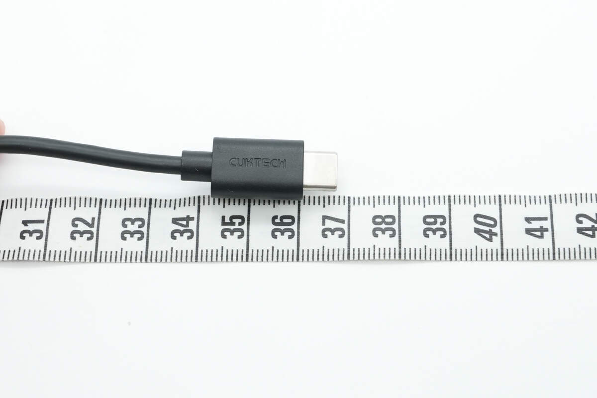
The length of the cable is about 36.8 cm (14.49 inches).
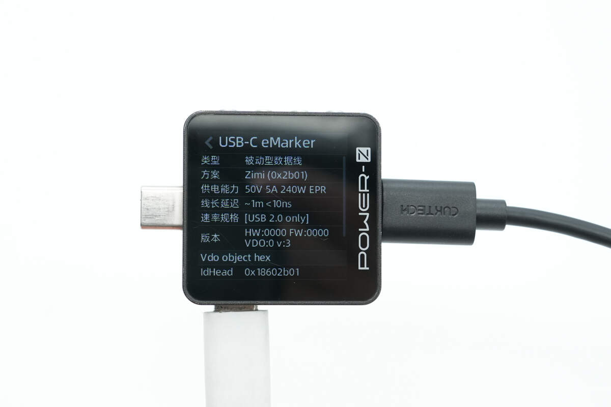
ChargerLAB POWER-Z KM003C shows that it has an E-Marker chip, with a power delivery capability of 50V/5A and data transfer capability of USB 2.0.
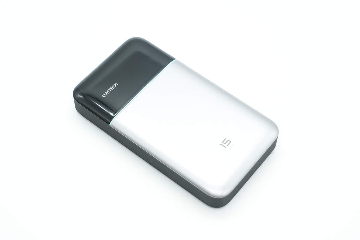
The power bank has a flat shape, with a lightweight and compact design, making it very delicate and refined.
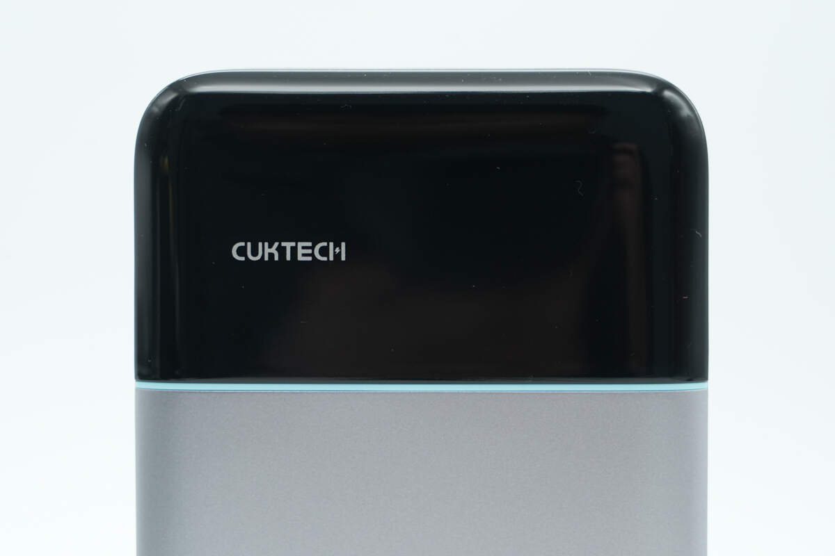
On the top black glossy decorative panel, the left side is printed with “CUKTECH.”
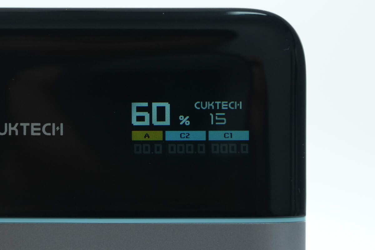
On the right side, there is a built-in high-definition TFT All-View screen that can display multiple real-time data such as battery level, power, current, and voltage.
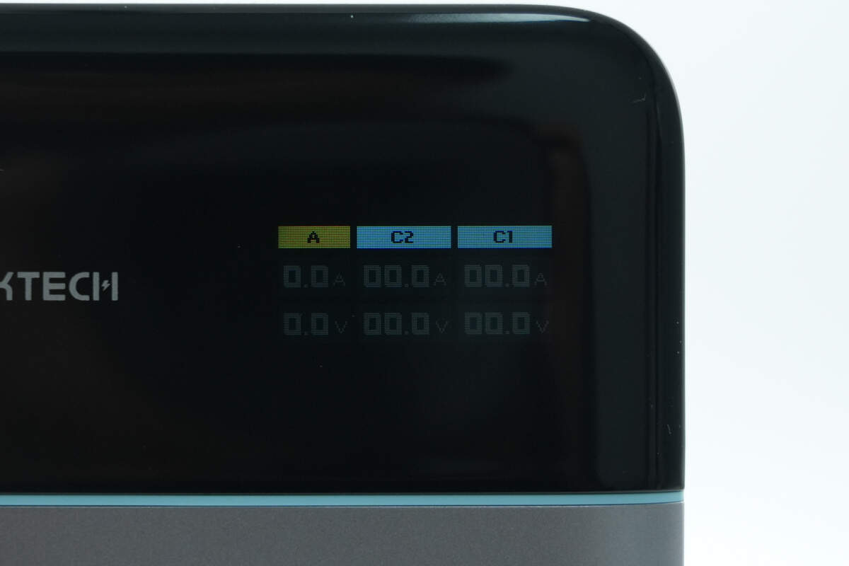
The visualization of current and voltage can even be displayed specifically for each USB port.
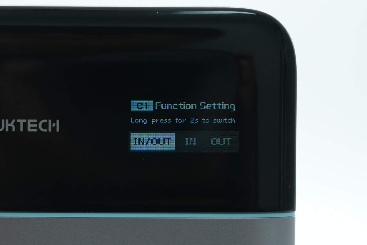
You can also set the USB-C1 port to input-only, output-only, or automatic mode as needed to prevent reverse charging.
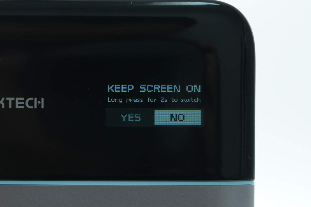
It also allows you to set the screen to stay on constantly or turn off after 60 seconds, supports 180° screen rotation, and includes a low-current mode, offering a wide range of features.
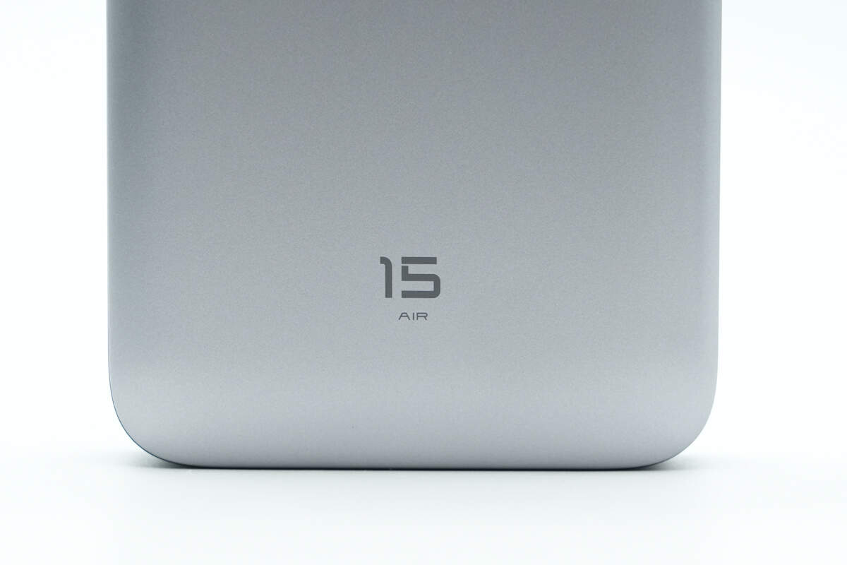
The bottom is printed with 15 AIR.
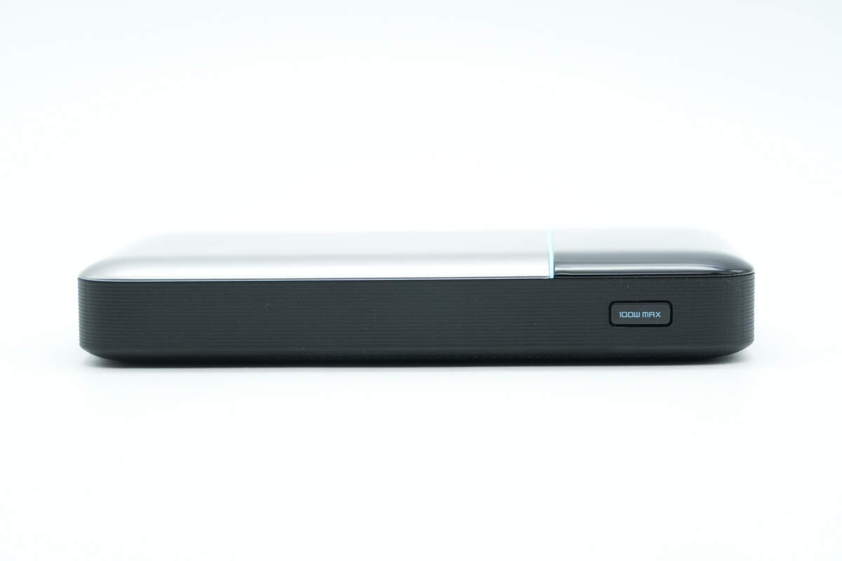
The textured design on the sides enhances the grip and overall handling comfort.
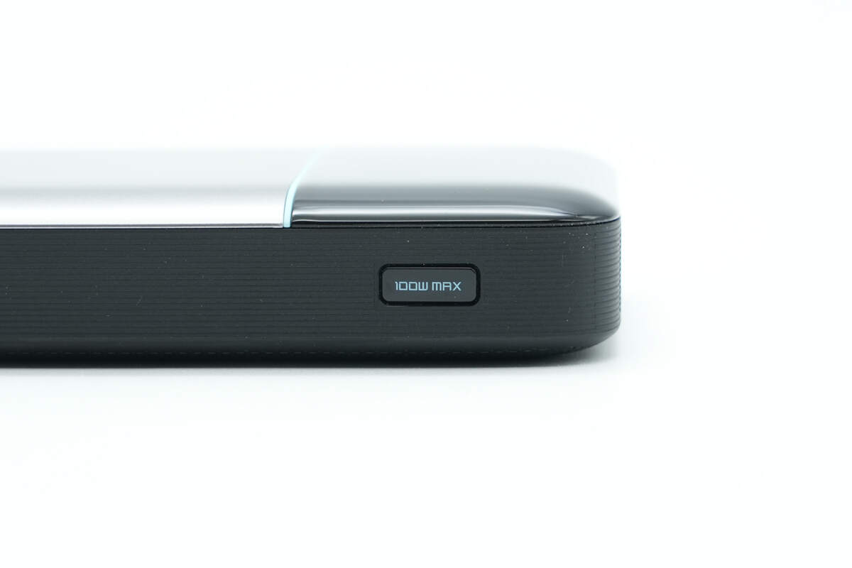
The power button is labeled with “100W MAX.”
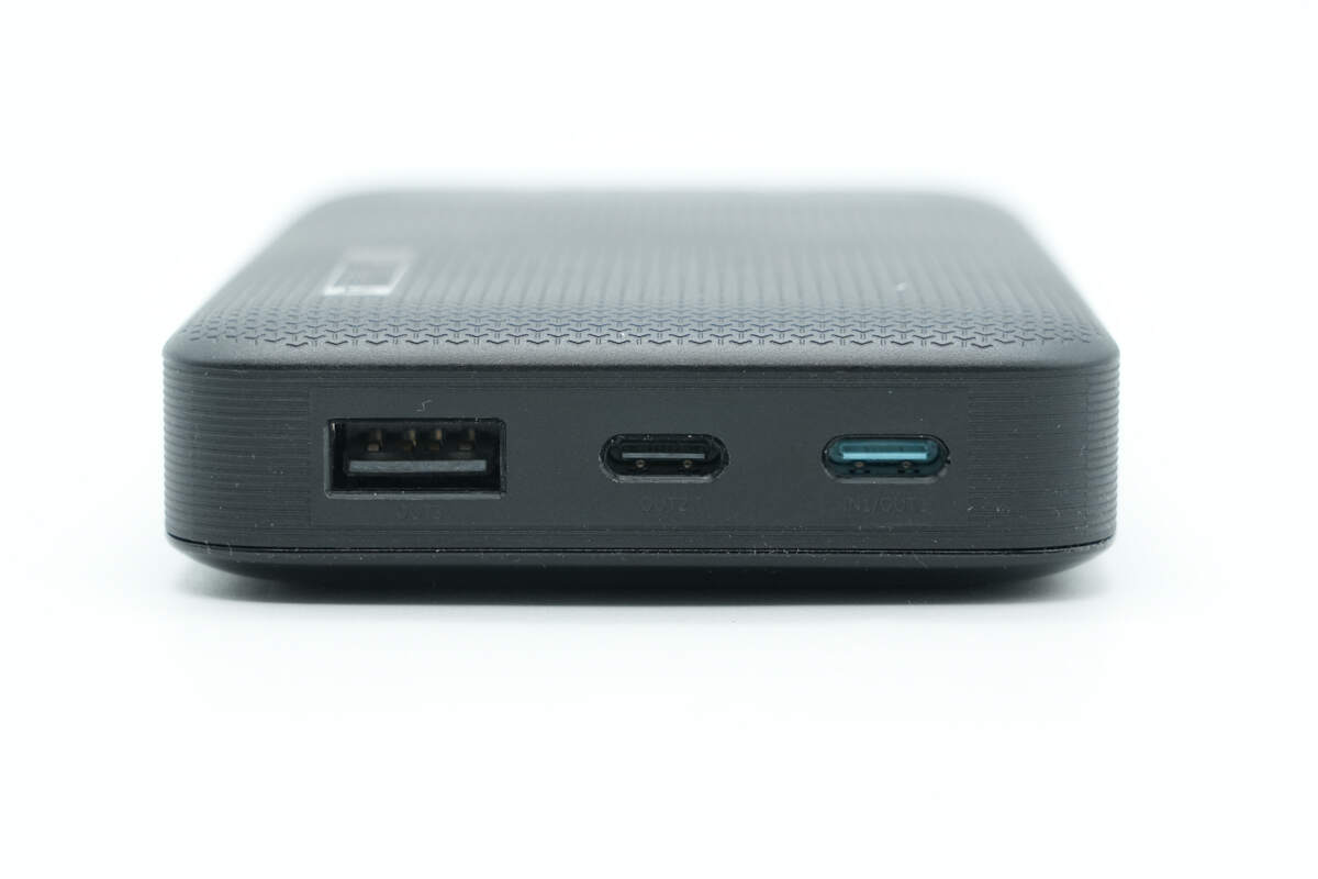
The top features two USB-C ports and one USB-A port.
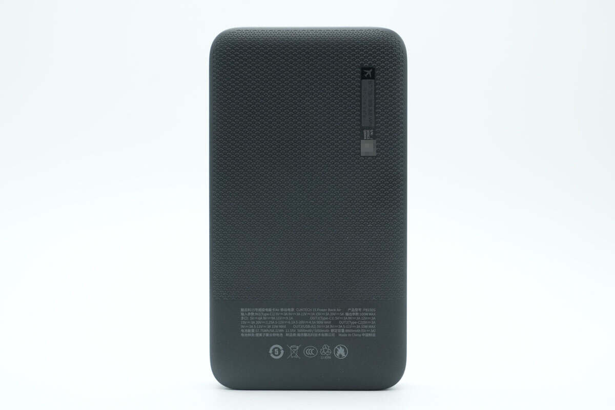
The spec info is also printed on the back.
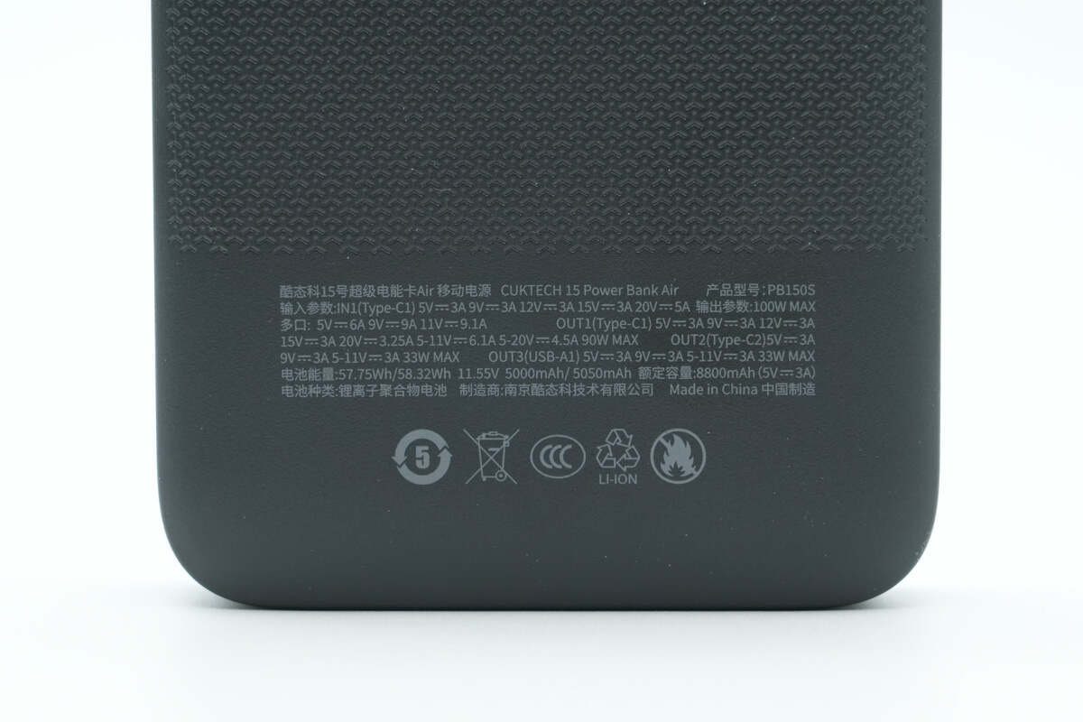
Model: PB150S
Battery type: Lithium-ion polymer battery
Rated capacity: 8800mAh (5V3A)
Battery energy: 57.75Wh / 58.32Wh, 11.55V, 5000mAh / 5050mAh
Input (Type-C1):
5V3A, 9V3A, 12V3A, 15V3A, 20V5A, 5-11V5A
Output (total):
100W max
Multi-port: 5V6A, 9V9A, 11V9.1A
Type-C1 output:
5V3A, 9V3A, 12V3A, 15V3A, 20V3.25A, 5-11V6.1A, 5-20V4.5A (90W max)
Type-C2 output:
5V3A, 9V3A, 5-11V3A (33W max)
USB-A1 output:
5V3A, 9V3A, 5-11V3A (33W max)
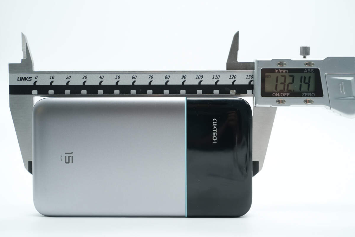
The length of the power bank is about 132.14 mm (5.2 inches).
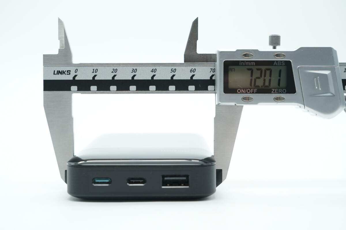
The width is about 72.01 mm (2.84 inches).
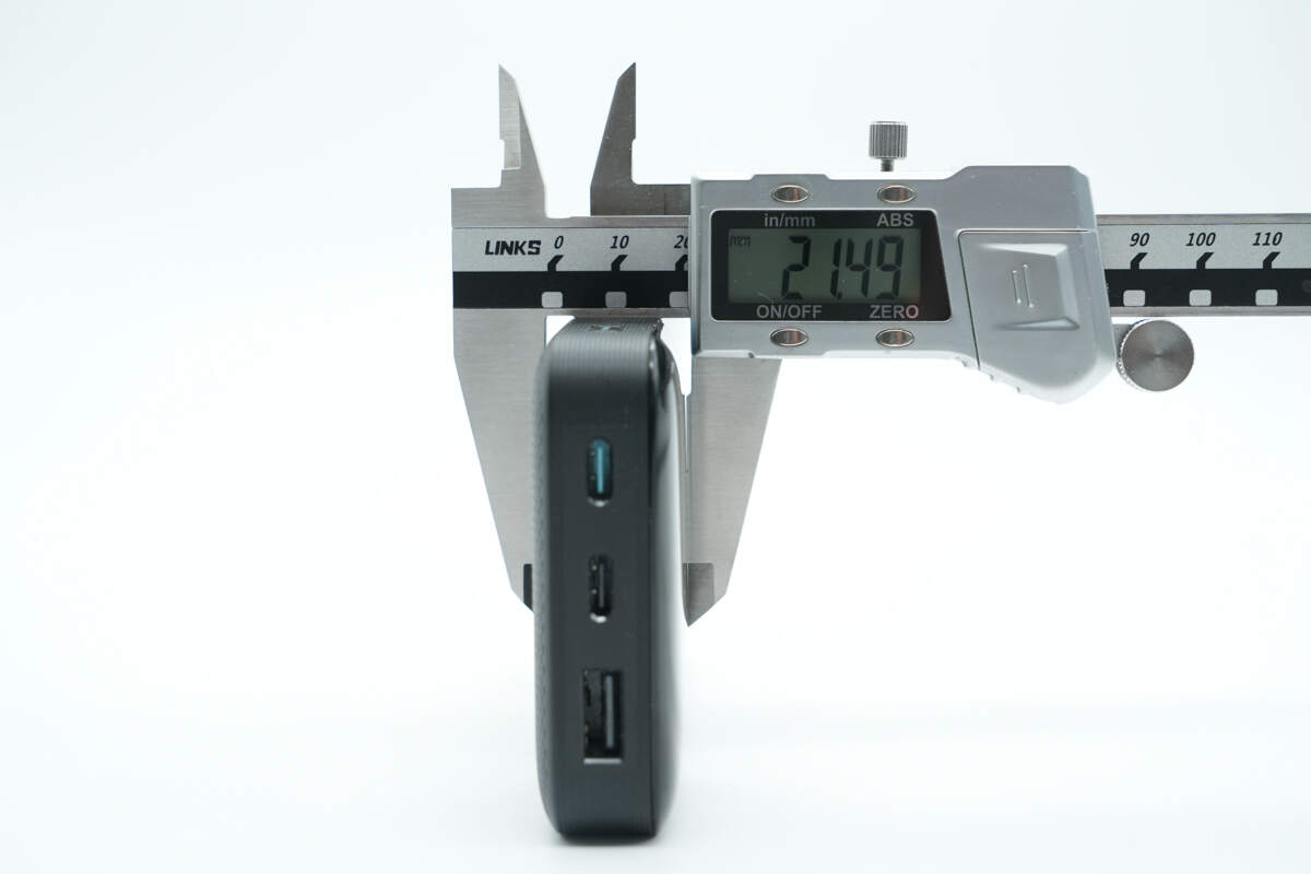
The thickness is about 21.49 mm (0.85 inches).
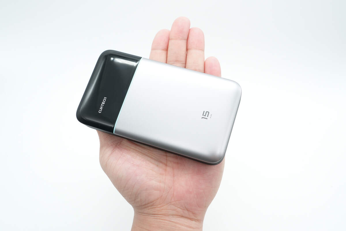
That's how big it is in the hand.
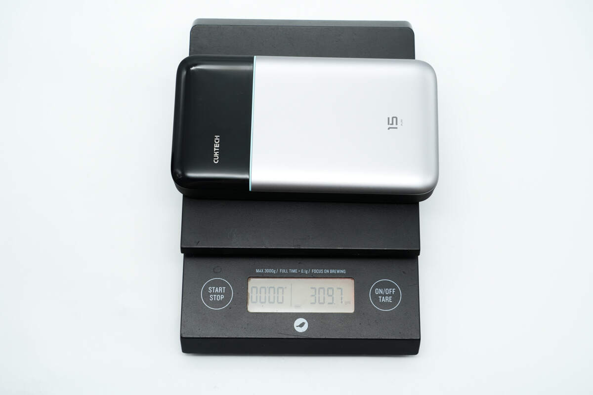
The weight is about 310 g (10.93 oz).
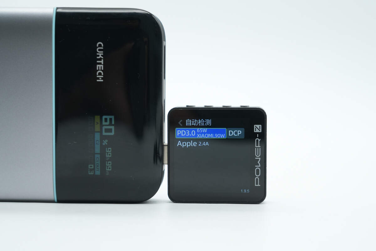
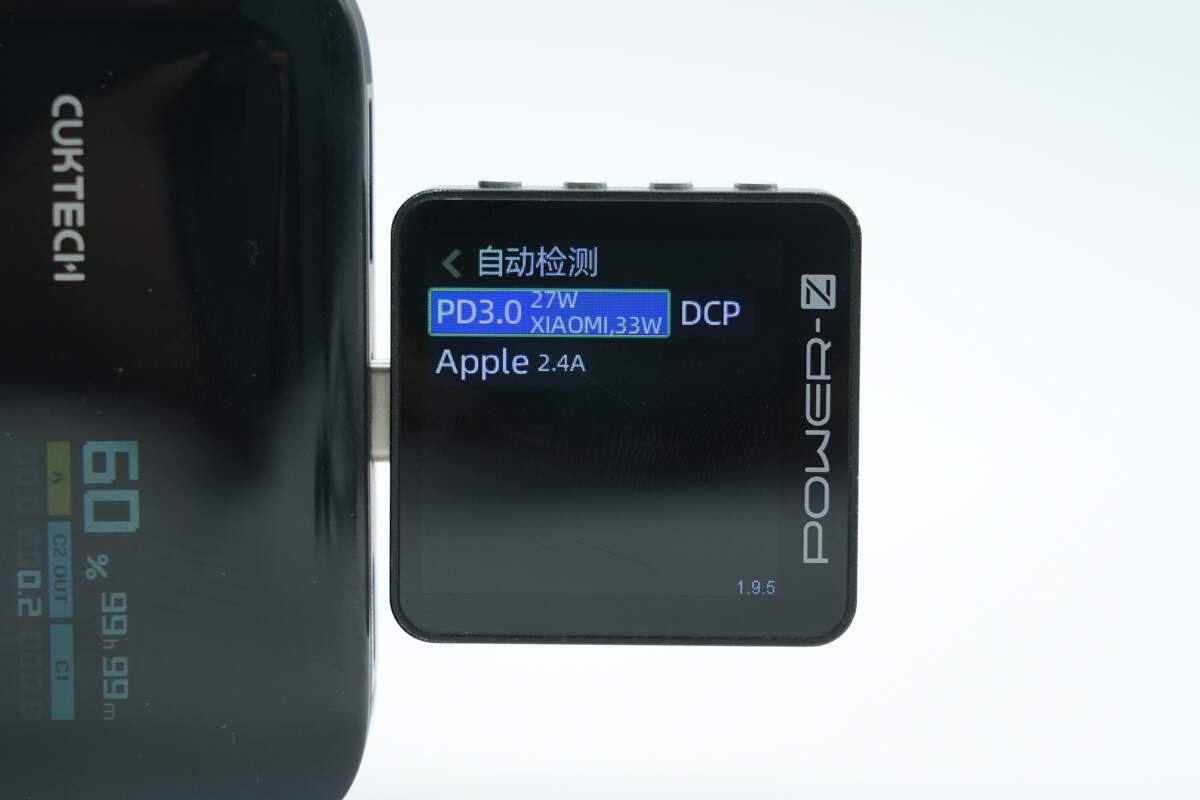
ChargerLAB POWER-Z KM003C shows that the USB-C1 port supports PD 3.0, DCP, Apple 2.4A charging protocols, as well as Xiaomi’s proprietary 90W fast-charging protocol.
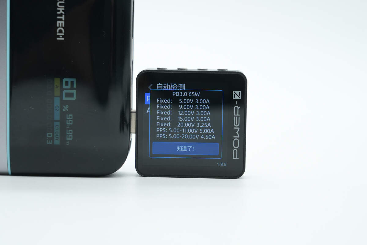
And it has five fixed PDOs of 5V3A, 9V3A, 12V3A, 15V3A, and 20V3.25A. It has two sets of PPS, which are 5-11V5A and 5-20V4.5A.
The USB-C2 port supports PD 3.0, DCP, and Apple 2.4A charging protocols, as well as Xiaomi’s proprietary 33W fast-charging protocol.
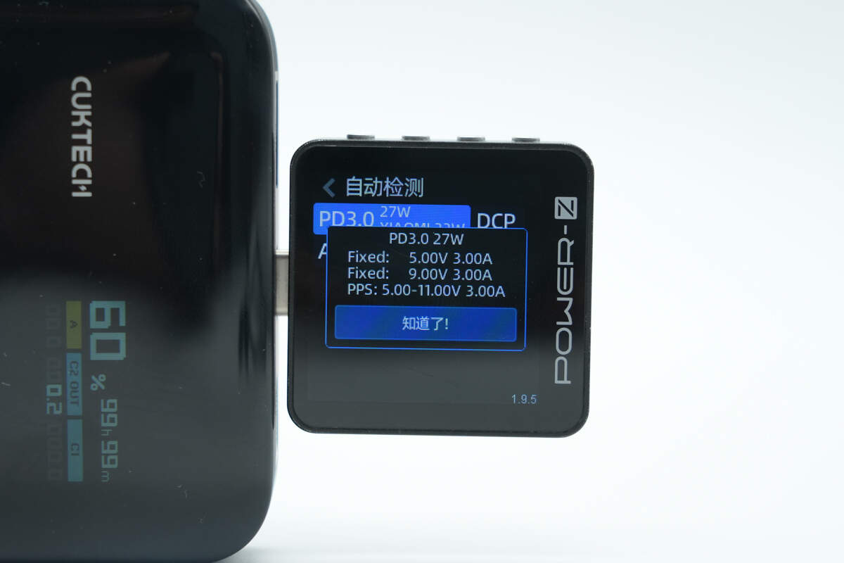
It has two fixed PDOs of 5V3A and 9V3A. It has one set of PPS, which is 5-11V3A.
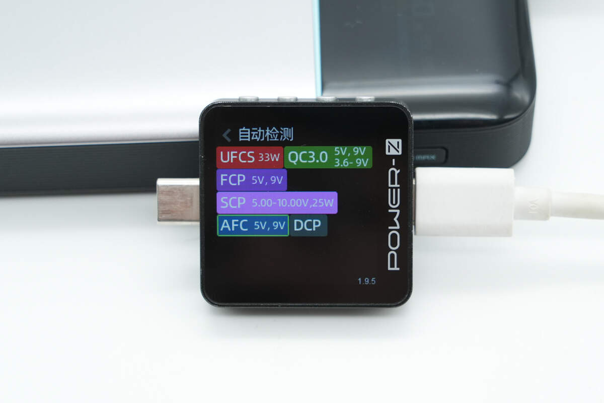
The USB-A can support UFCS, QC3.0, FCP, SCP, AFC, and DCP charging protocols.
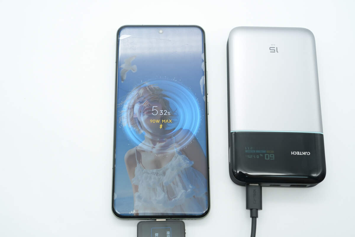
Using the USB-C1 port to charge the Xiaomi 15 Pro successfully activates the 90W Surge fast charging.
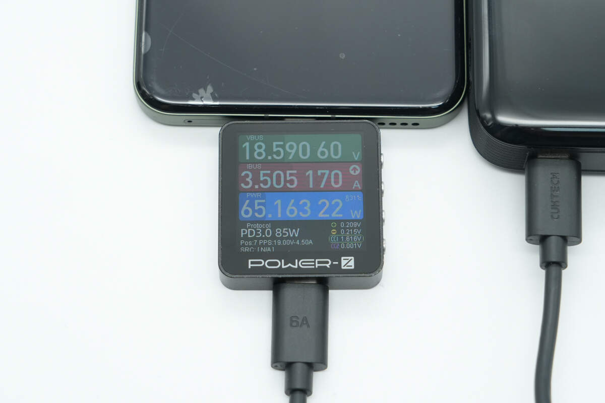
When the charging power climbs to a stable level, the power is about 65W.
Teardown
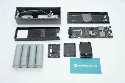
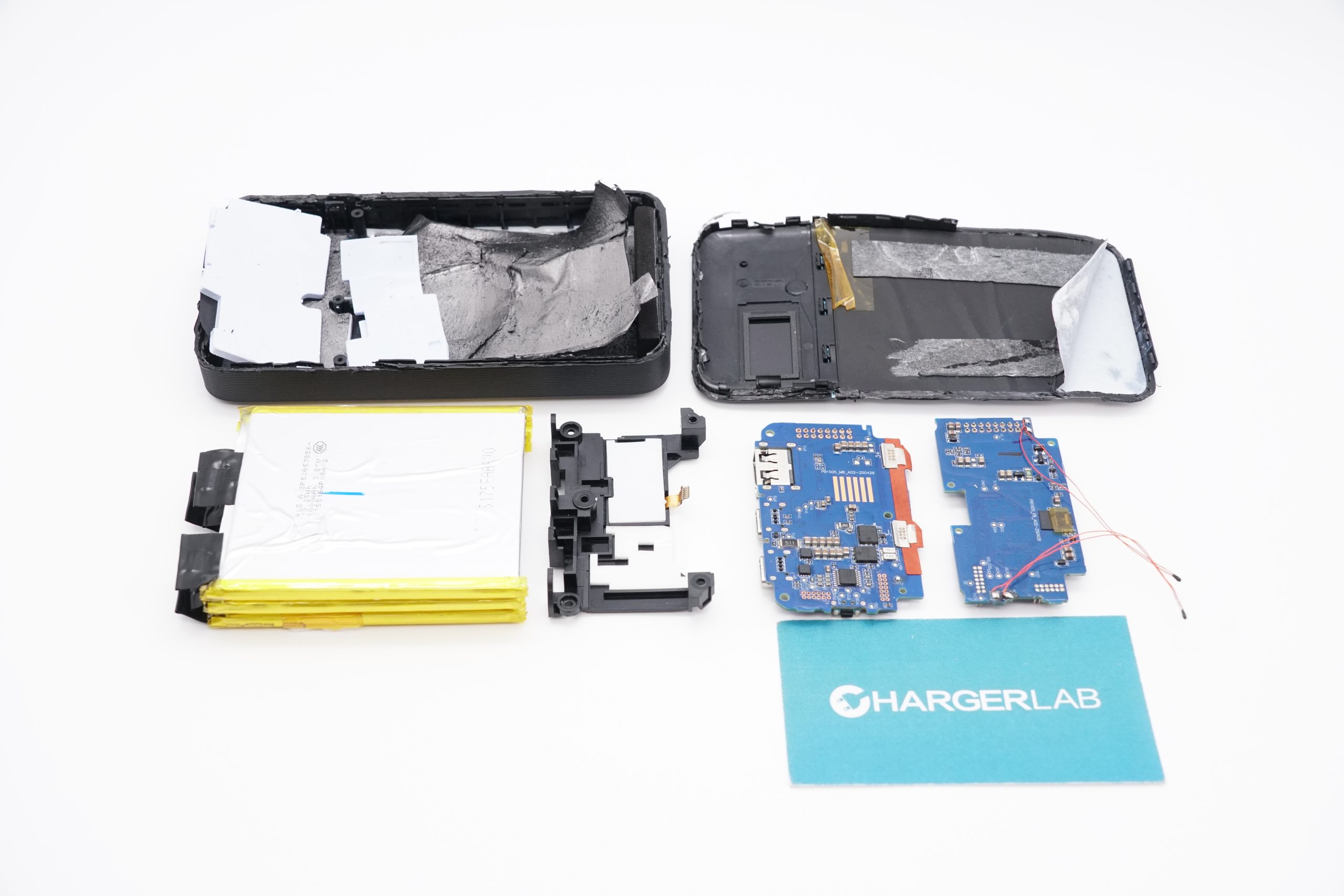
Next, let's take it apart to see its internal components and structure.
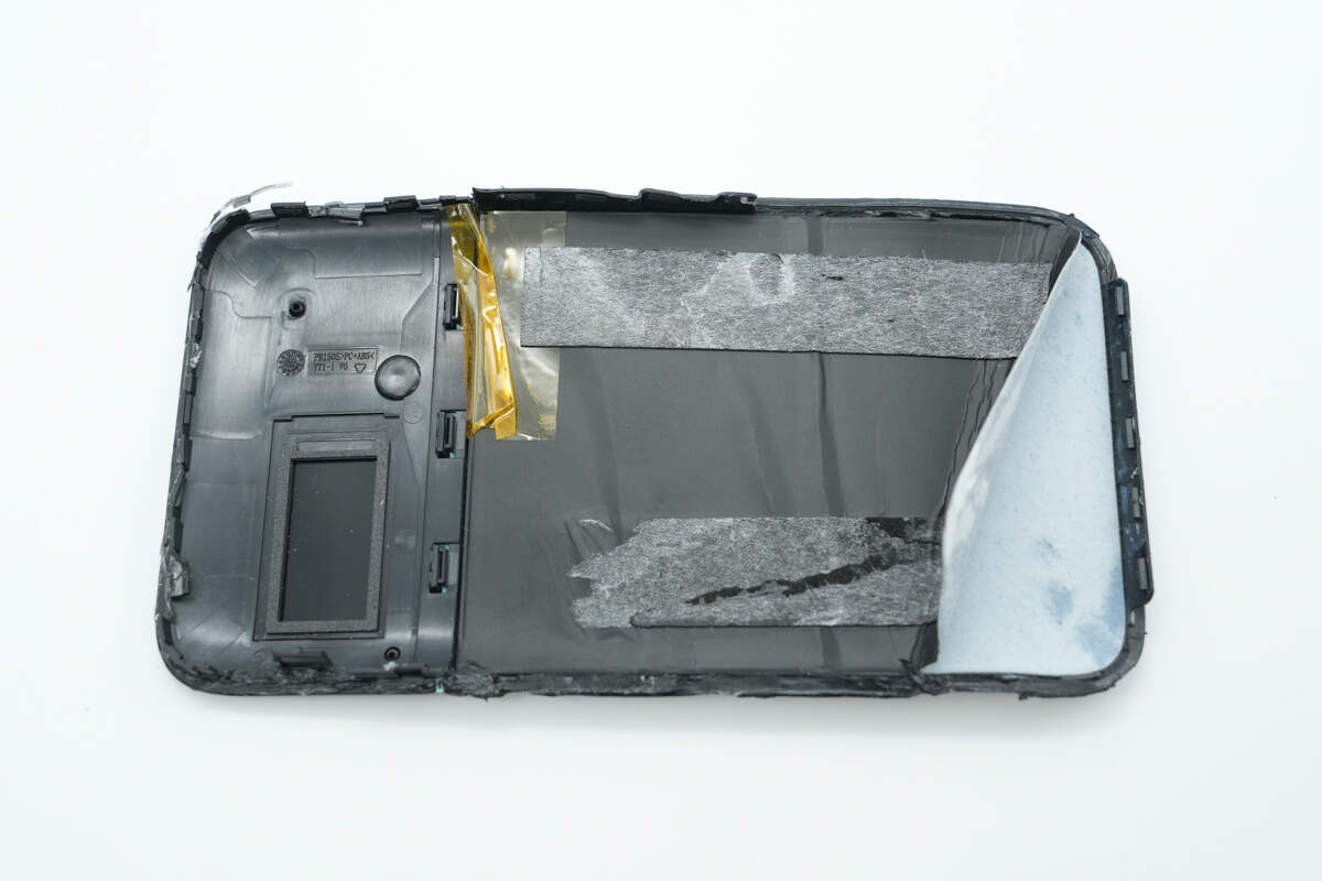
After opening the casing, you can see that the interior is lined with cushioning pads and aerogel.
Foam padding is placed at both ends of the battery cell, along with insulating tape for added safety. The screen is supported and secured with a plastic bracket, while the PCB board is fastened with screws.
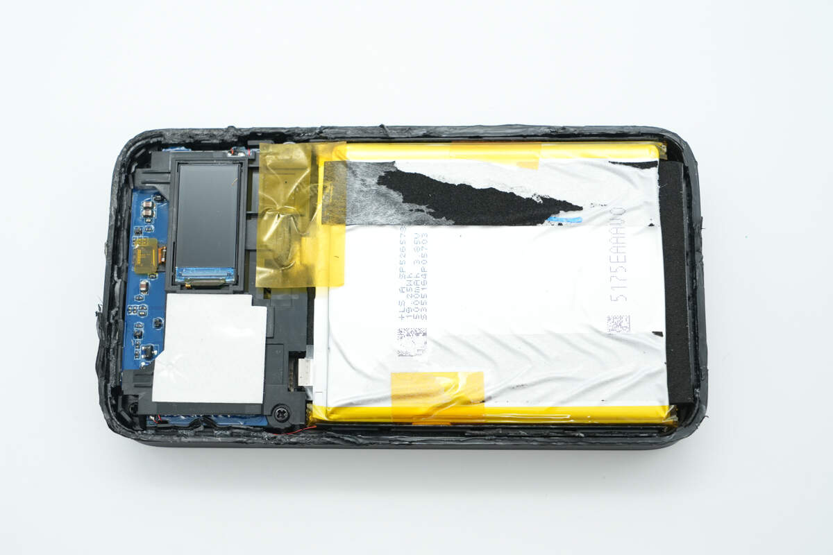
Remove the screws to take out the plastic bracket.
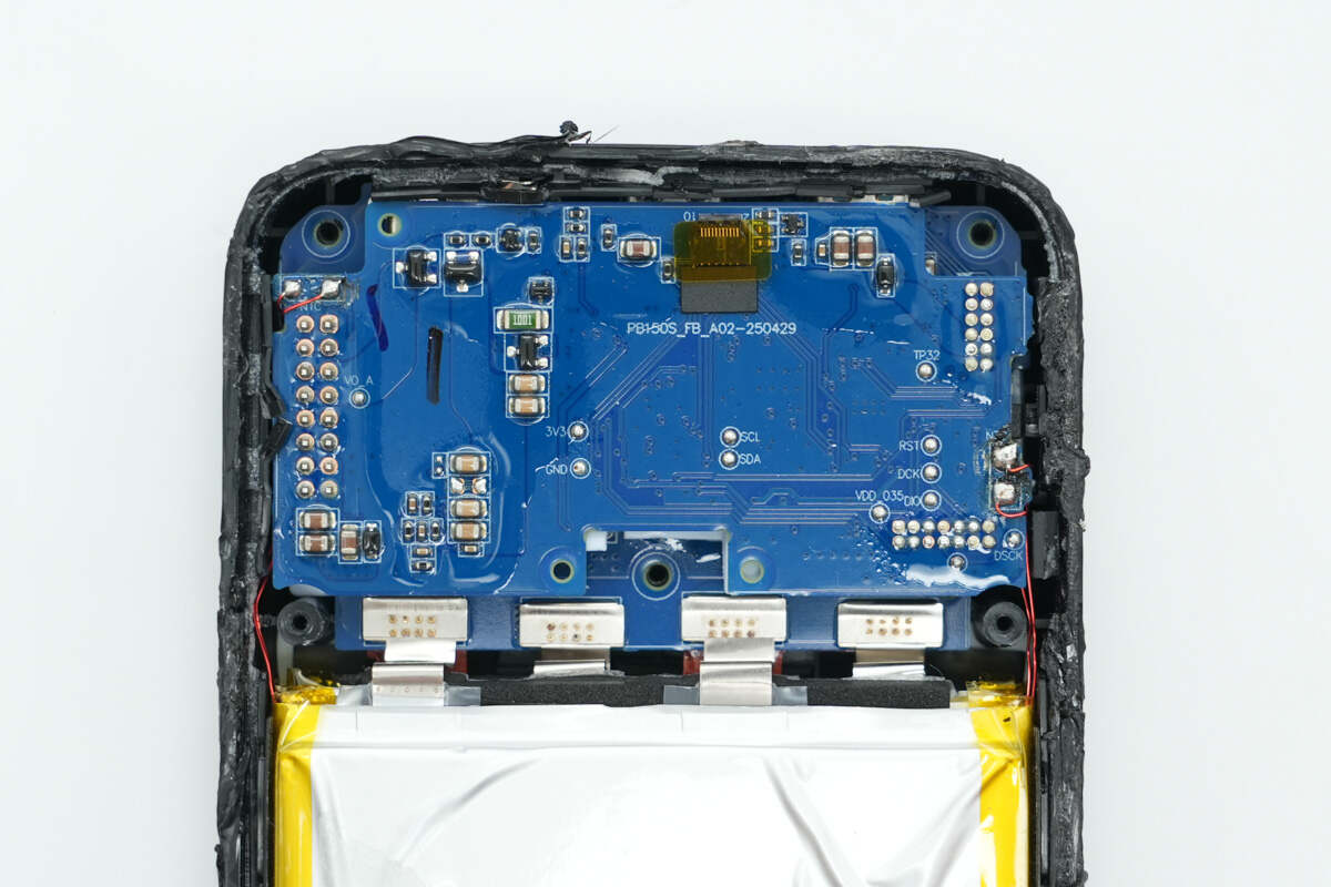
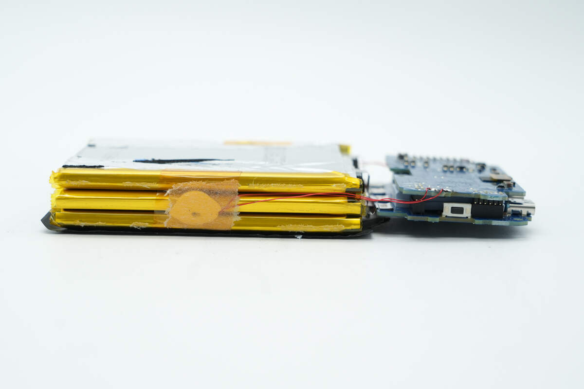
The PCBA module features a dual-layer design, with the battery cell connected to the lower PCB via nickel strips.
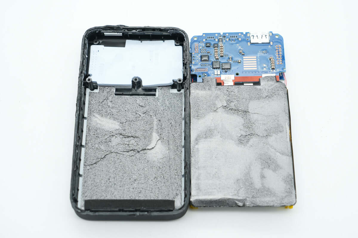
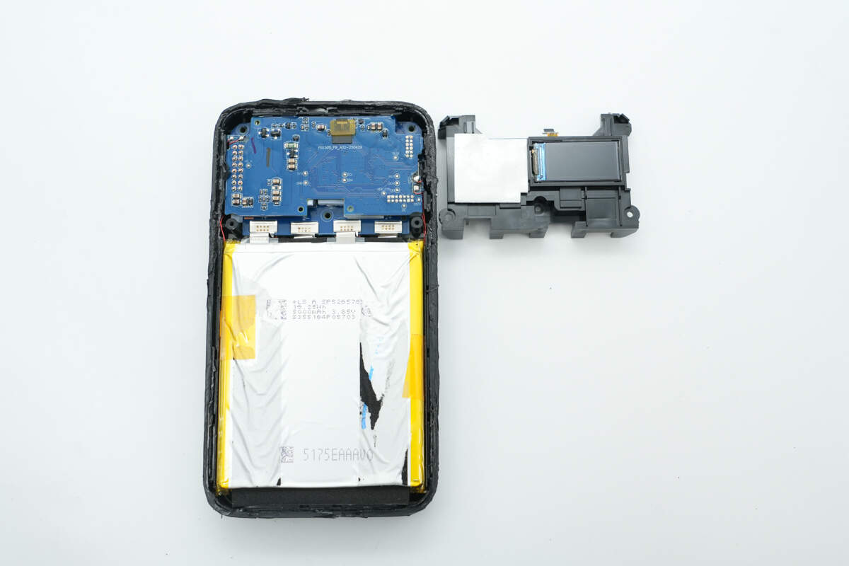
After removing the battery cell and the PCBA module, the other half of the casing is found to have thermal pads and graphite stickers attached.
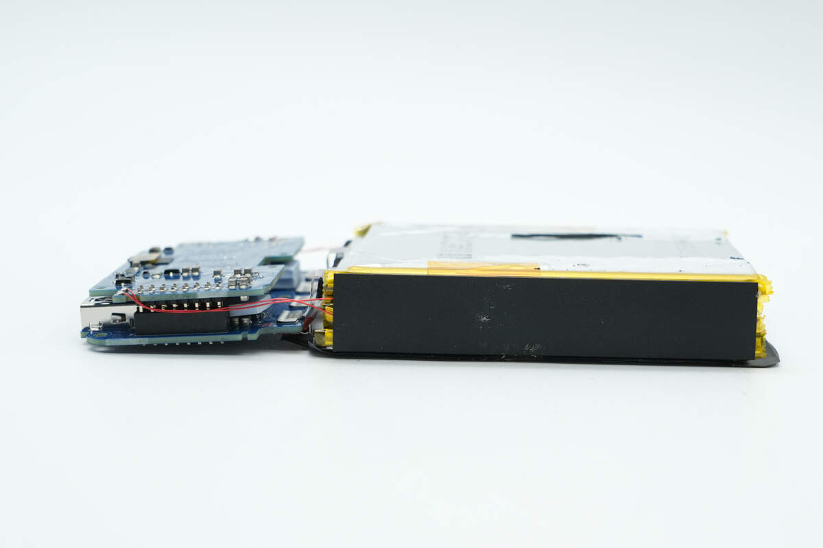
Both sides of the battery cell are lined with cushioning foam.
After removing the foam padding, you can see that a thermistor has been glued in place for temperature monitoring.
There is also a thermistor installed on the other side of the battery cell.
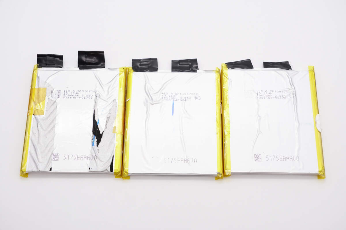
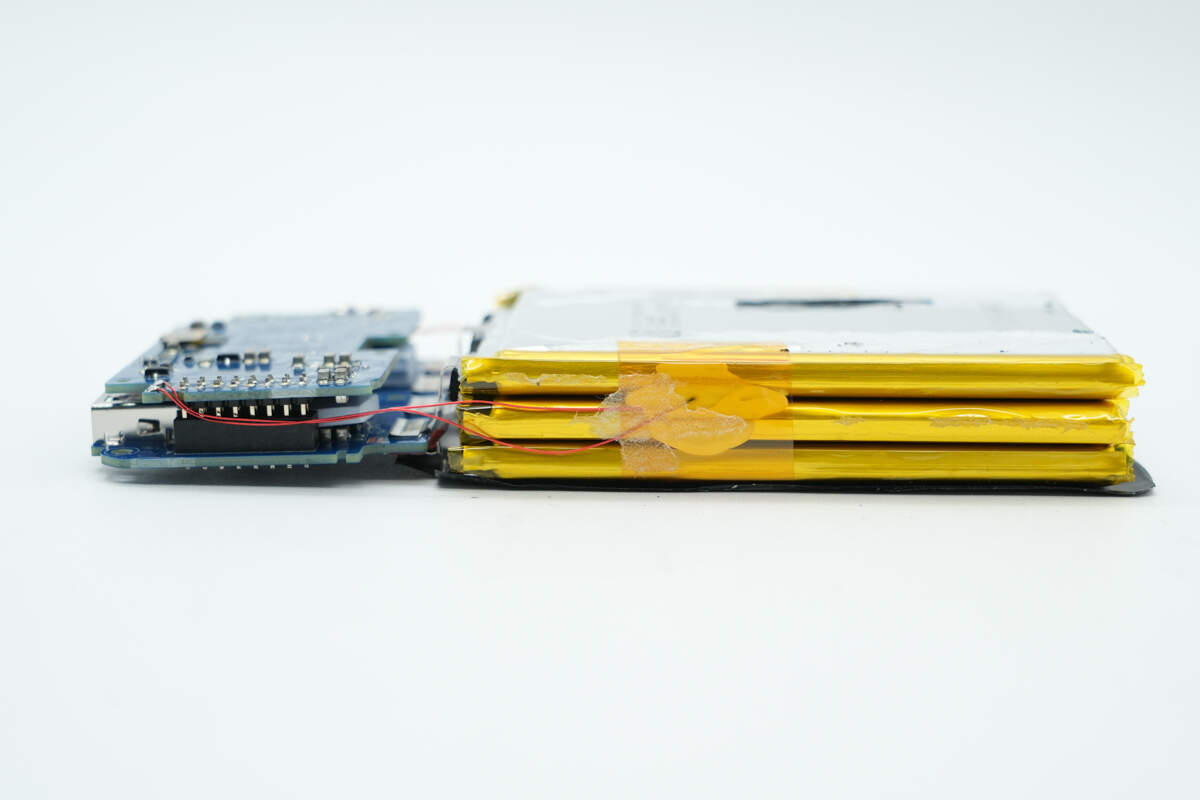
After separating the battery cells, all three cells have the same part number and are sourced from LS.
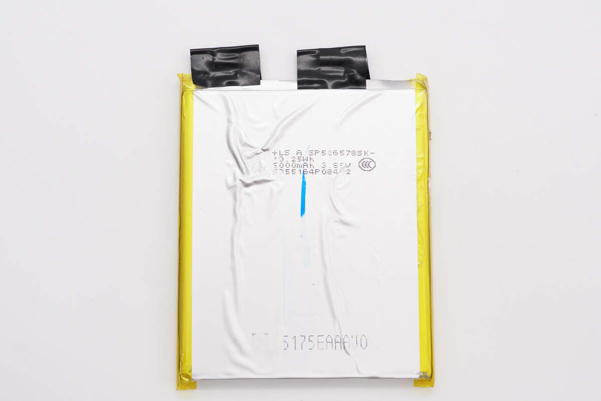
The LS battery cells have the model number SP526578SK, with a rated voltage of 3.85V, a capacity of 5000mAh, and an energy of 19.25Wh.
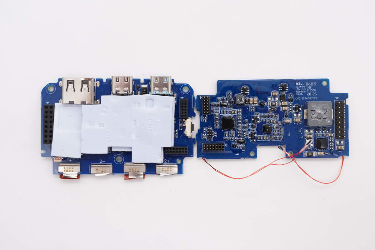
Both PCBs are coated with conformal coating for protection, and a thermal pad is placed between the layers.
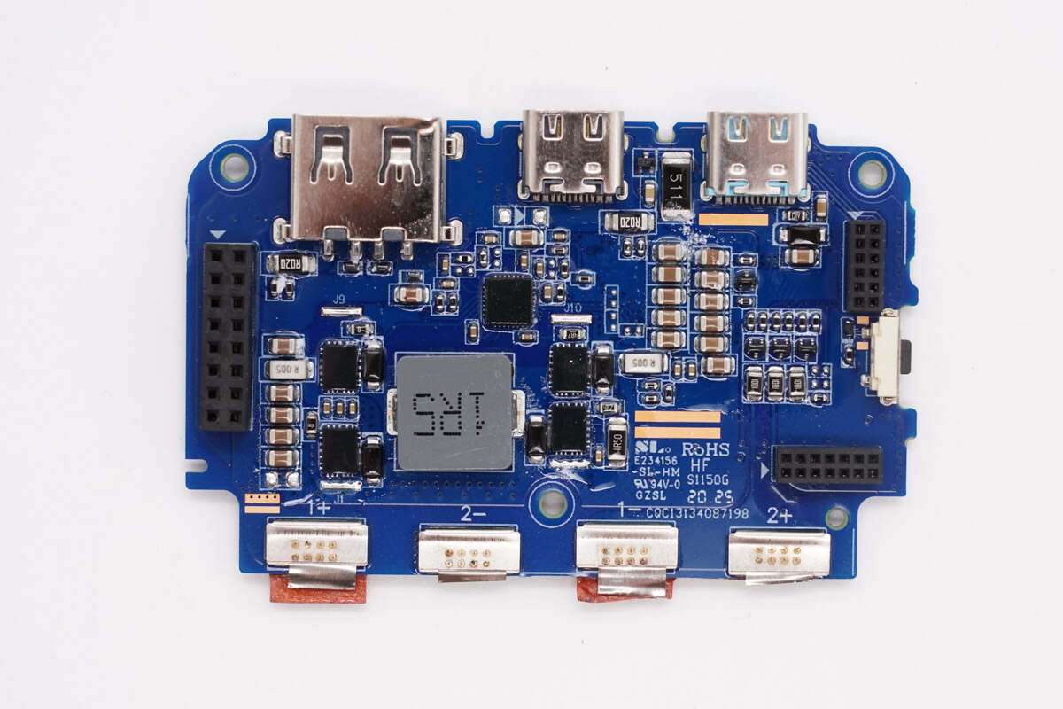
On the front side of the PCB, there is a synchronous bidirectional buck-boost controller for the USB-C1 bidirectional power conversion circuit, along with buck-boost MOSFETs and buck-boost inductors.
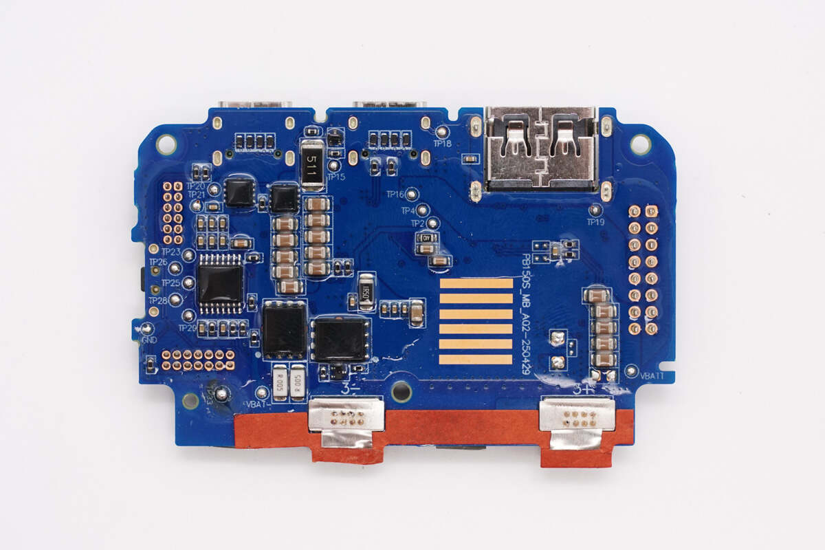
On the back side, there is a lithium battery protection chip, protection MOSFETs, and the VBUS MOSFET for the USB-C1 port.
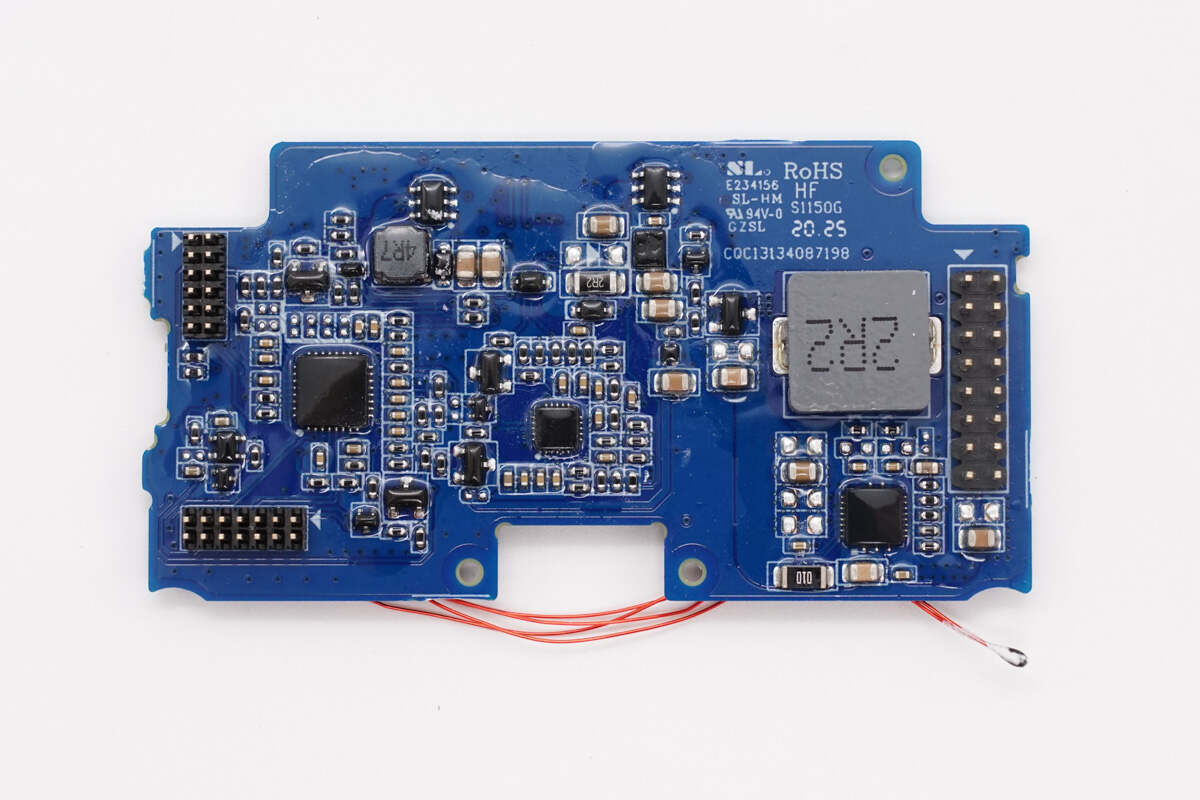
The front side of the other PCB contains the controllers and buck-boost inductors for the remaining two ports, as well as components such as the MCU and protocol chips.
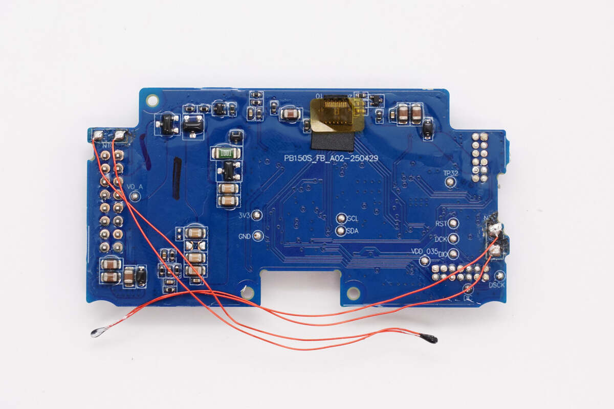
The other side is soldered with two thermistors.
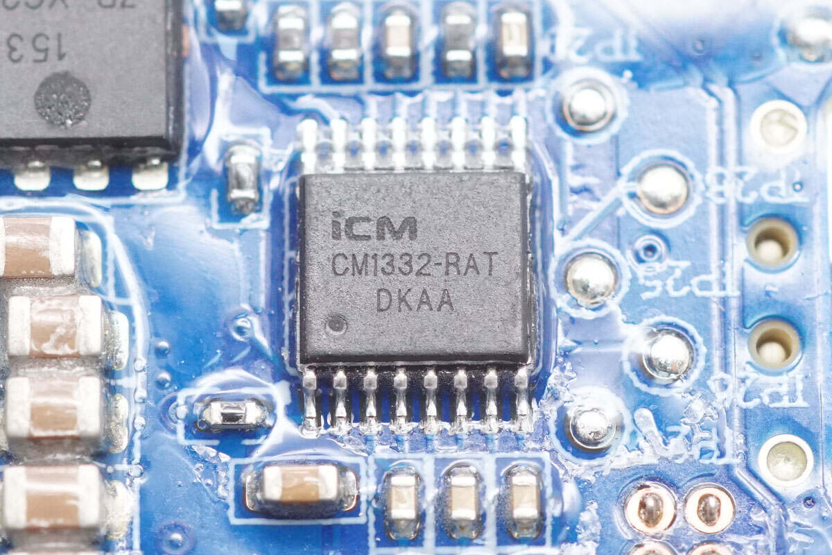
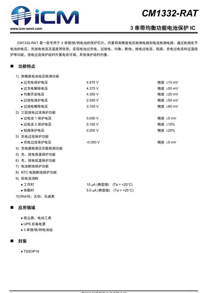
The lithium battery protection chip is from iCM, model CM1332-RAT. It is specifically designed for 3-series lithium, iron, or sodium batteries and integrates high-precision voltage and current detection circuits. By monitoring the voltage of each cell, charge/discharge current, and temperature, it provides protection features such as overcharge, overdischarge, cell balancing, open circuit, discharge overcurrent, short circuit, charge overcurrent, and overtemperature. The discharge overcurrent protection delay is adjustable via an external capacitor, while other protection delays are built-in.
Here is the information about iCM CM1332-RAT.
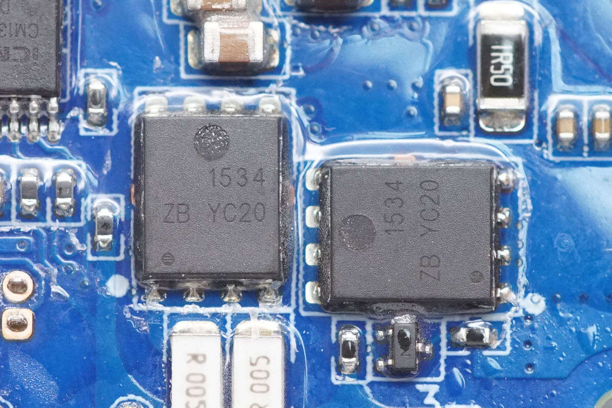
The two lithium battery protection MOSFETs are marked with 1534 and use a DFN5×6 package.
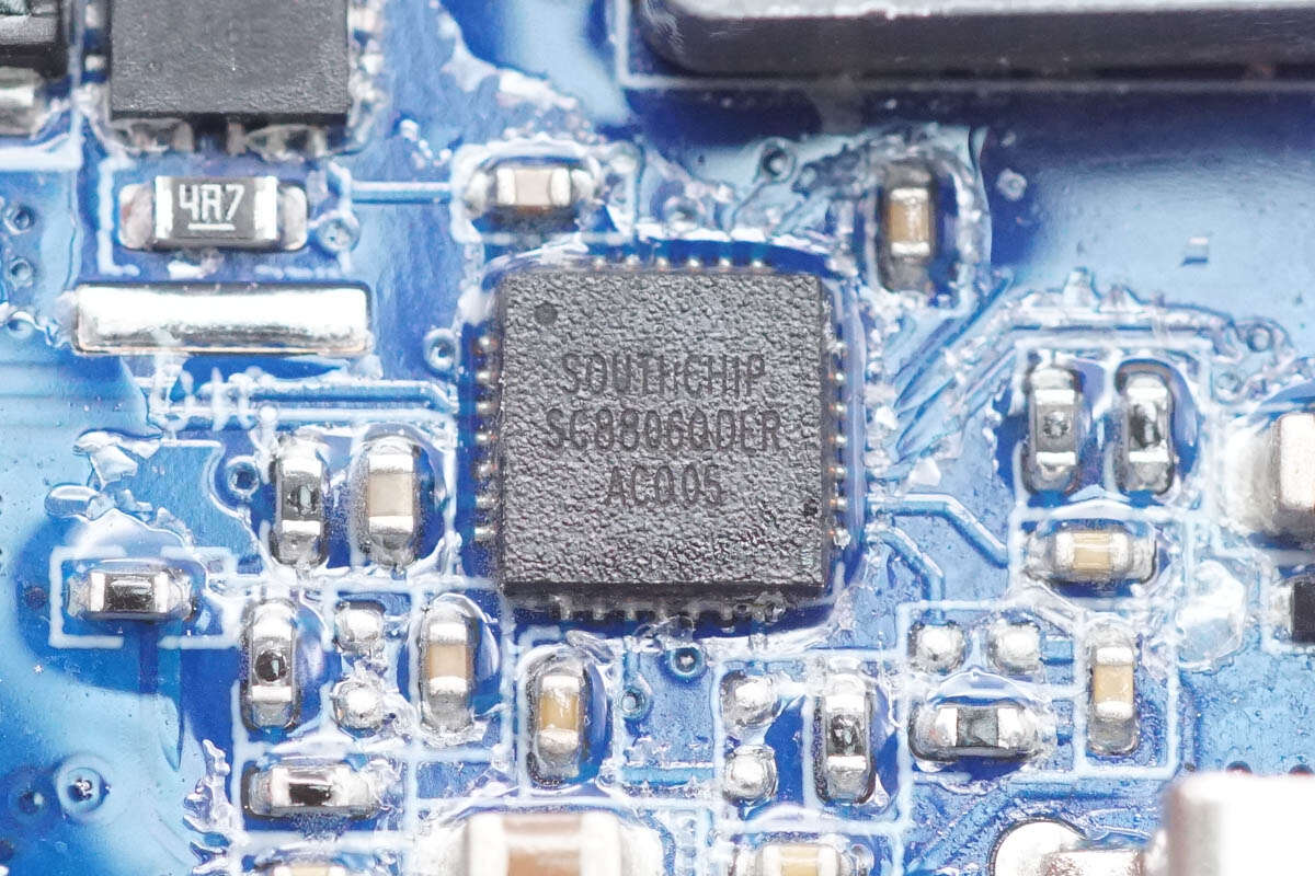
The synchronous bidirectional buck-boost controller used for the USB-C1 port is the SC8806 from SouthChip. It can manage battery charging regardless of whether the input voltage is lower than, higher than, or equal to the battery pack voltage. It supports an input voltage range of 3.5–24V and an output voltage range of 3–24V. It is compatible with charging configurations of 1 to 4 lithium cells. Both output voltage and current limits can be adjusted via an I²C interface. The chip also integrates a 10-bit ADC and comes in a QFN 4×4 package.
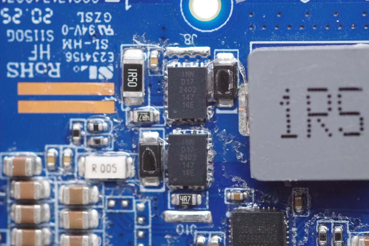
The four synchronous bidirectional buck-boost MOSFETs are from Innoscience, marked with "D17," and are model INN040FQ043A. These are 40V enhancement-mode GaN (gallium nitride) MOSFETs with a low on-resistance of 4.3mΩ. They feature extremely low gate charge and conduction resistance, along with a very compact package size. These characteristics make them well-suited for high-frequency DC-DC converters, point-of-load applications, RF envelope tracking, laptop chargers, power banks, and motor drives. They come in an FCQFN 3×4mm package.
Here is the information about Innoscience INN040FQ043A.
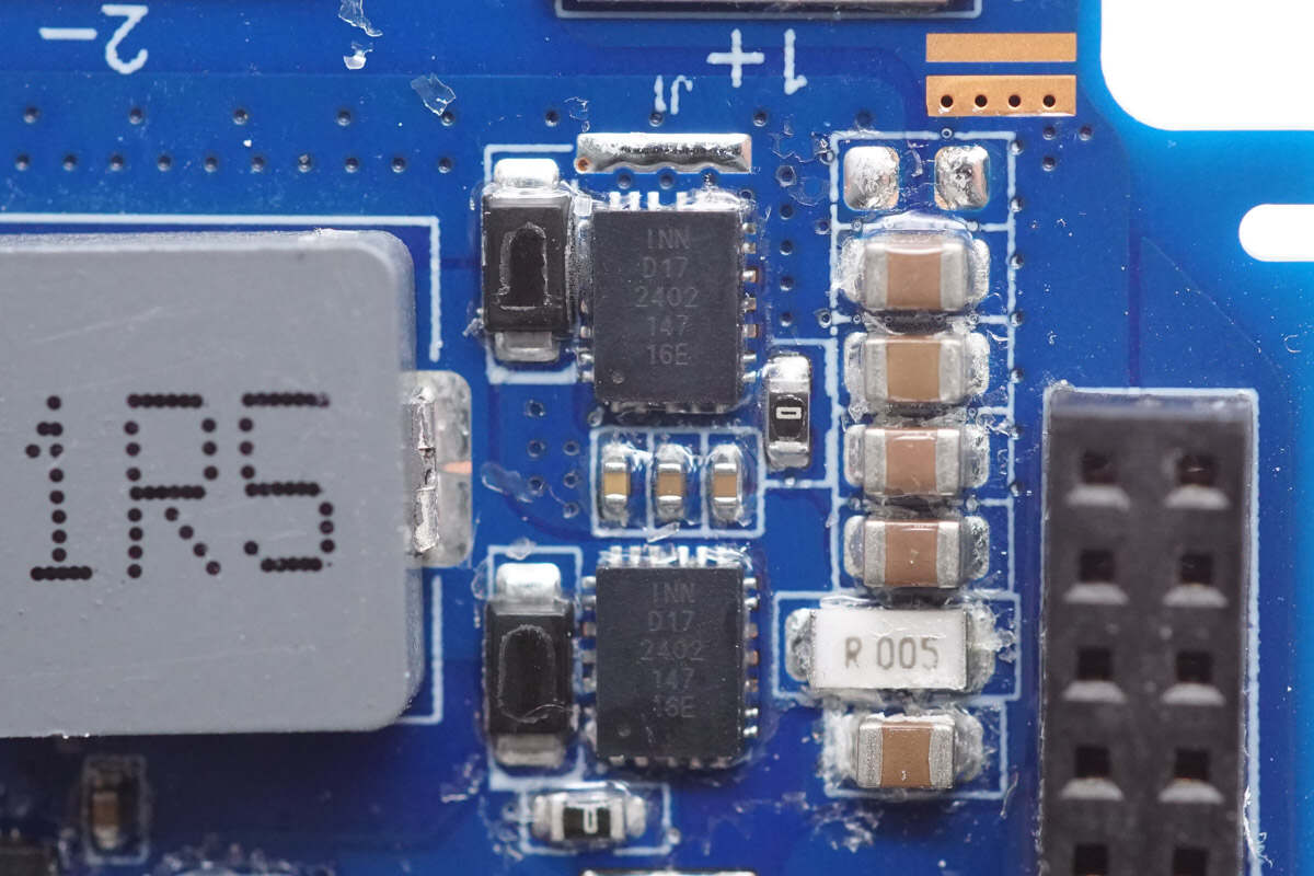
Close-up of the other two Innoscience INN040FQ043A MOSFETs.
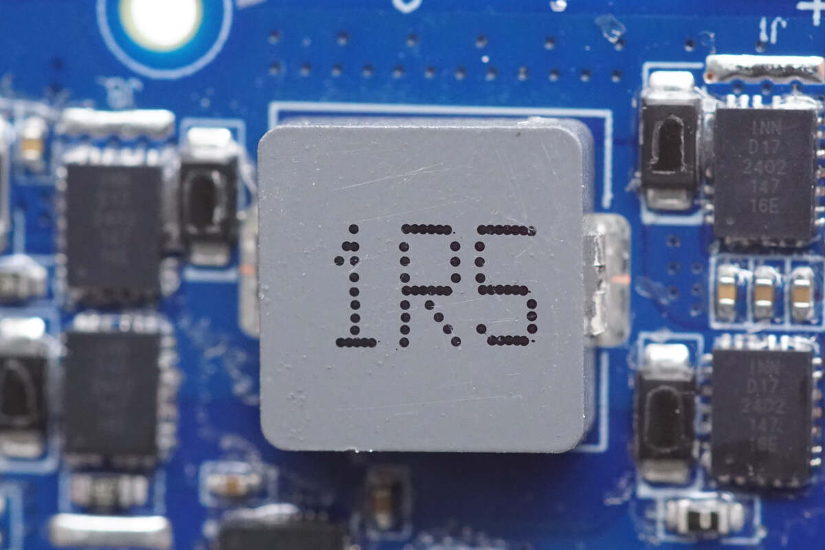
Close-up of the paired 1.5 μH buck-boost inductor.
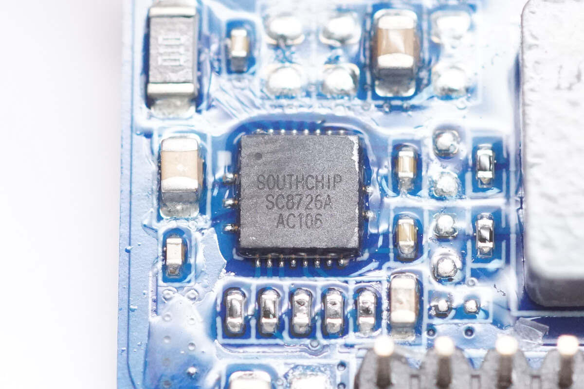
The synchronous buck-boost converter used for the other two ports is the SC8726A from SouthChip. This is a highly efficient converter with four integrated power MOSFETs, designed to simplify system design, reduce PCB space, and minimize the bill of materials. Its high efficiency also helps reduce thermal losses.
The SC8726A supports a wide input voltage range of 2.7–22V and an output voltage range of 2.4–22V. It features an integrated I²C interface, allowing users to configure output voltage, current limits, and switching frequency.
Based on a current-mode control architecture, the SC8726A offers output current limiting, dynamic voltage adjustment, internal current limiting, short-circuit protection, and over-temperature protection, ensuring safe and stable operation under various conditions. It comes in a 21-pin 4×4 mm QFN package.
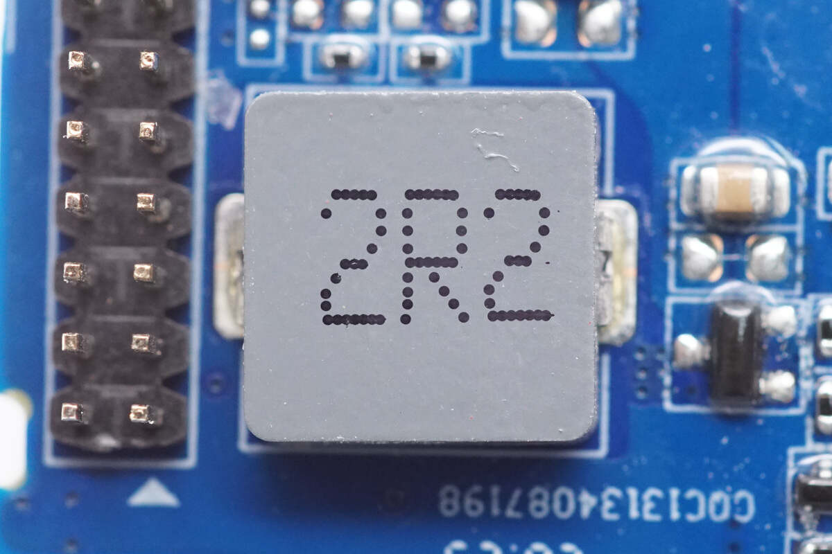
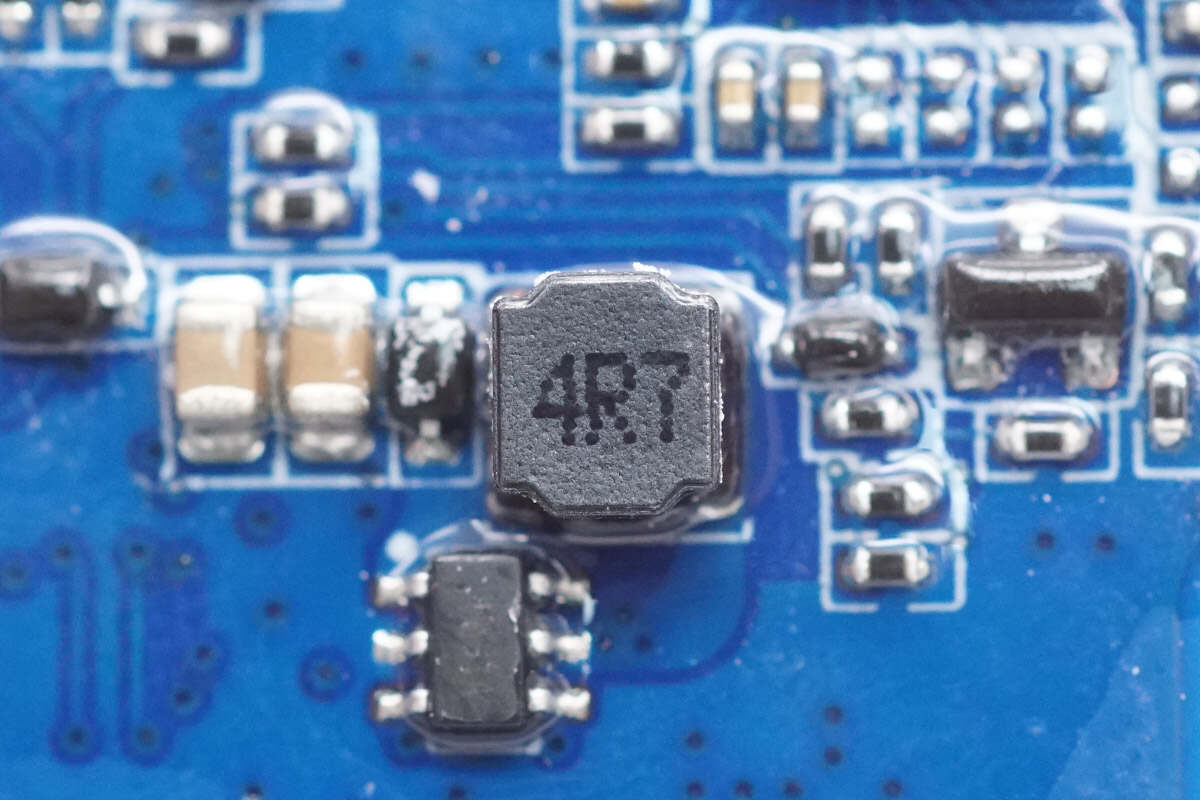
Close-up of the paired 2.2 μH buck-boost inductor.
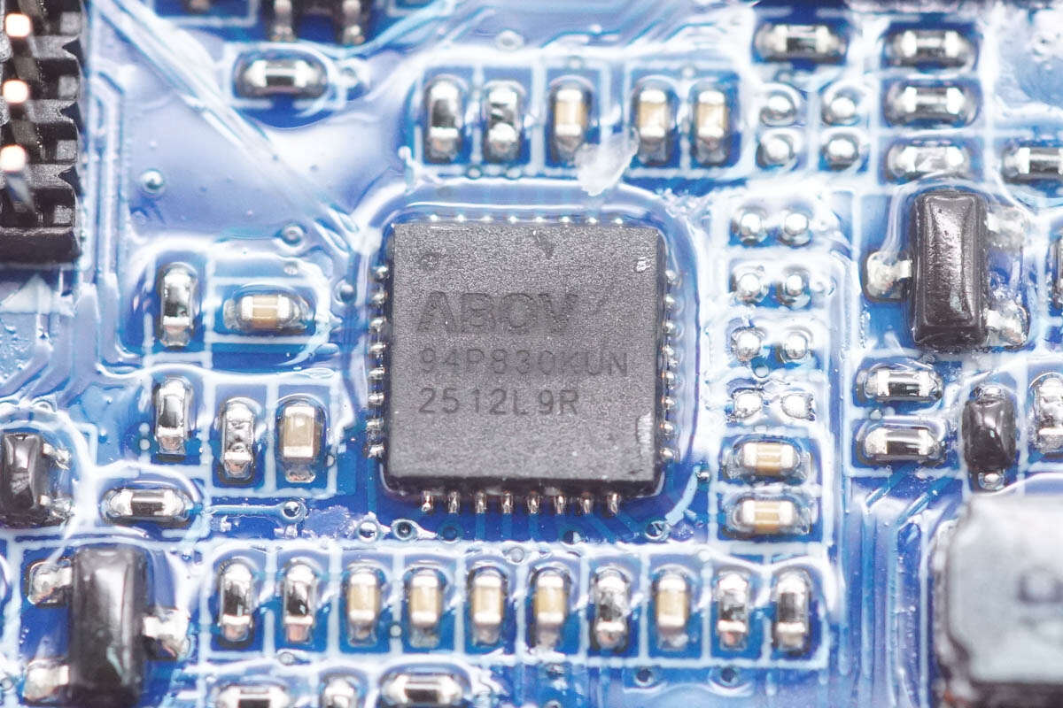
The protocol chip for the three USB ports is from ABOV, model A94P830KUN, housed in a QFN32 package.
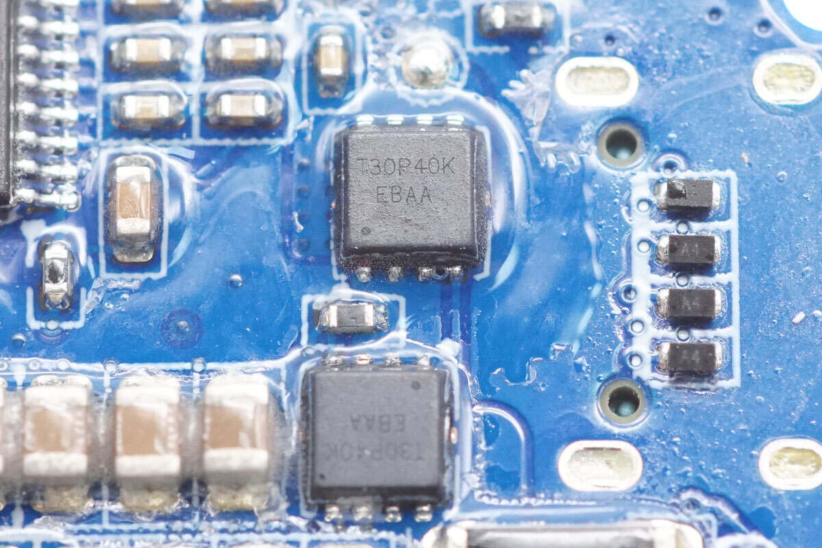
The VBUS MOSFET for the USB-C1 port is from iCM, marked with T30P40K and model CMT30P40K. It is a P-channel MOSFET rated for -30V, with an on-resistance of 8mΩ, and comes in a compact PDFN 3.0×3.0 mm package.
Here is the iCM CMT30P40K.
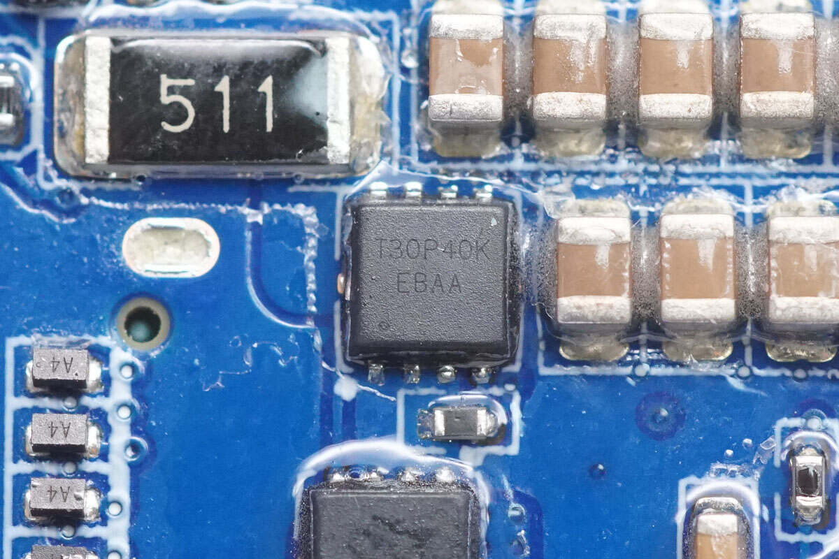
Here’s a close-up of the other CMT30P40K MOSFET. Two of these MOSFETs are connected in a back-to-back configuration to prevent reverse current.
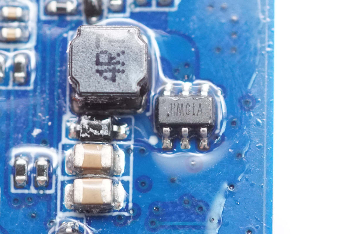
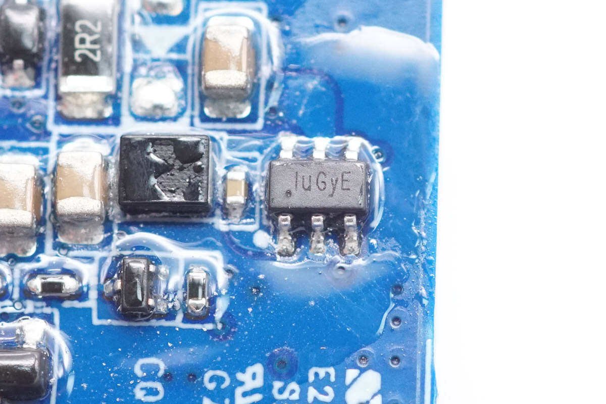
The boost chip is from SILERGY, marked with HM and model SY7302. It operates at a switching frequency of 1 MHz and integrates a 200 mΩ MOSFET. The chip comes in a compact SOT23-6 package.
Close-up of the paired 4.7 μH boost inductor.
The synchronous buck converter used to step down the battery pack voltage for the MCU is from SILERGY, and model SY8301. This converter integrates internal MOSFETs, supports input voltages up to 40V, and delivers up to 1A output current. It comes in a compact SOT23-6 package.
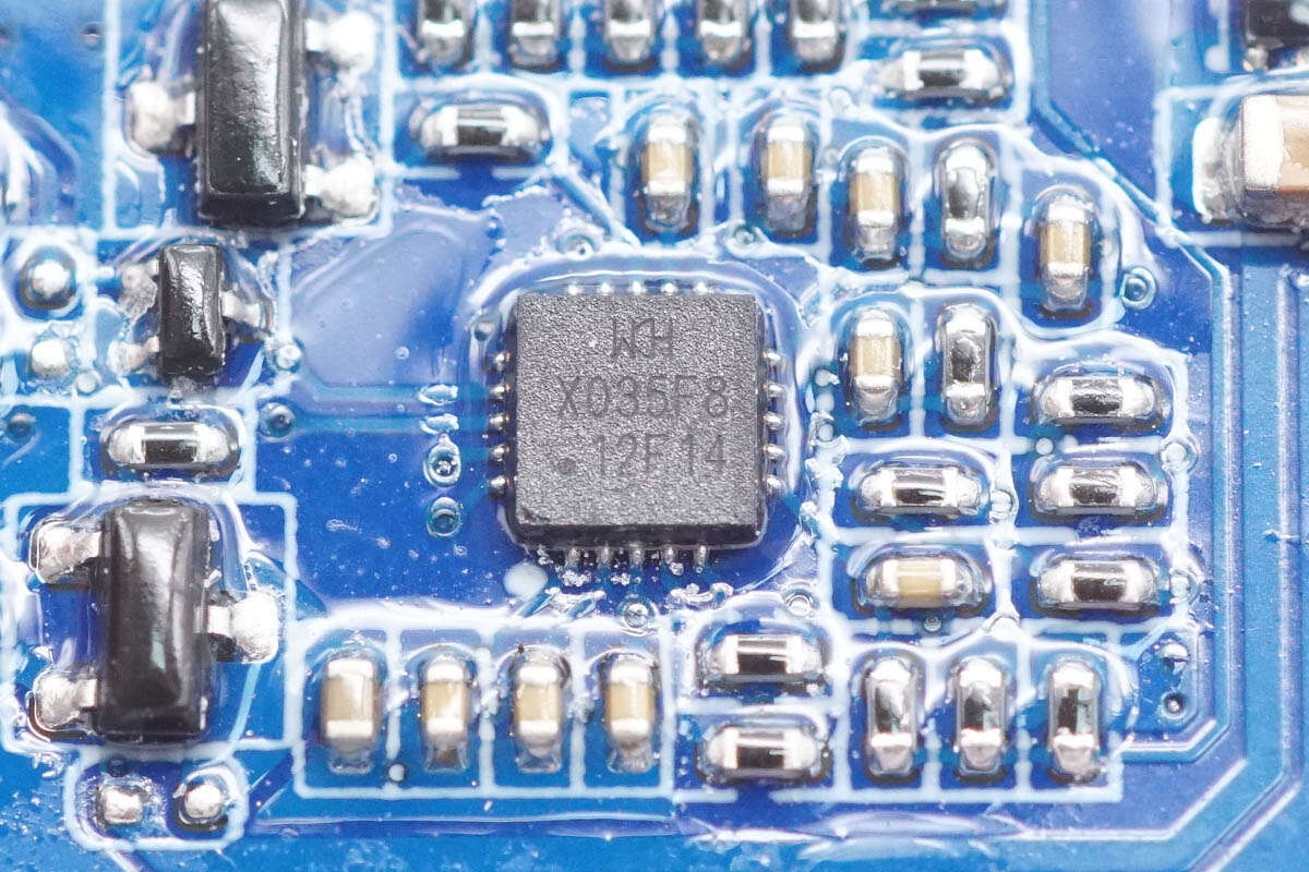
The MCU driving the display is from WCH, model CH32X035F8U6, based on a RISC-V core, with 62K flash, 20K RAM, integrated ADC, operational amplifier, and USB and PD physical layers.
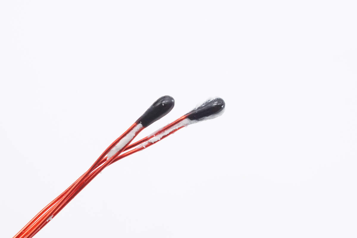
Close-up of the thermistor.
Well, those are all components of the CUKTECH 15 Power Bank Air.
Summary of ChargerLAB
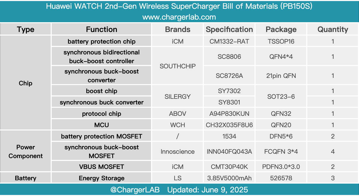
Here is the component list of the CUKTECH 15 Power Bank Air for your convenience.
After taking it apart, we found that it uses a new generation silicon-carbon anode battery jointly developed and customized by CUKTECH and LS, with a single cell thickness as thin as 0.52 cm. It is equipped with the iCM CM1332-RAT lithium battery protection chip and thermistors for temperature control and protection, such as overcharge and overdischarge.
The PCBA module uses a dual-layer design and features SouthChip SC8806 and SC8726A controllers paired with ABOV A94P830KUN protocol chip to manage charging and discharging for the three ports. GaN devices adopt Innoscience INN040FQ043A, used to achieve higher conversion efficiency and lower temperatures.
Related Articles:
1. Teardown of Huawei WATCH 2nd-Gen Wireless SuperCharger (CW05)
2. Teardown of xFusion’s FusionWatt 2000W Platinum Server Power Supply
3. Teardown of CUKTECH 10 GaN Charger Ultra (AD1204U)