Introduction
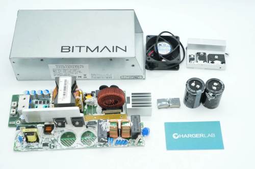
In this teardown, we’re looking at a 1600W power supply from Bitmain, designed for cryptocurrency mining. The power supply features a metal enclosure and is secured with screws. At the input end, there is a C14 power socket and a cooling fan. The output end includes internal terminal posts to secure the output wires. The unit supports 200–240VAC input and is rated to output 12V DC at 133A.
The power supply has a total of 10 output wires, each terminating in a 6-pin PCIe connector, used to power external devices. It adopts a PFC + LLC + synchronous rectification architecture and internally uses a silicon carbide diode from ROHM. Now, let’s take a look inside this Bitmain power supply to examine its design and components.
Product Appearance
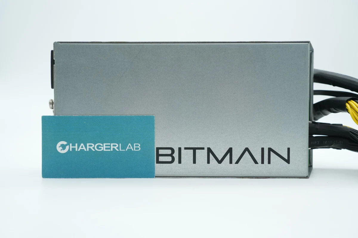
The Bitmain 1600W power supply features a metal enclosure with the word "BITMAIN" printed on the front.
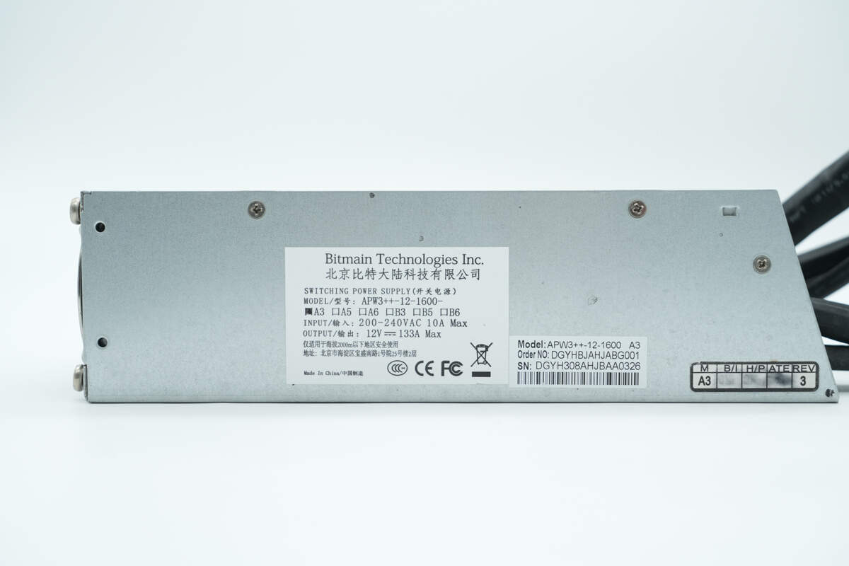
An information label is affixed to the side.
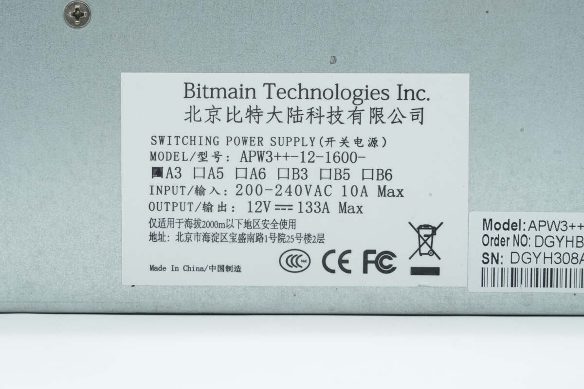
Beijing Bitmain Technologies Co., Ltd.
Model: APW3++-12-1600-A3
Input: 200–240VAC 10A Max
Output: 12V 133A Max
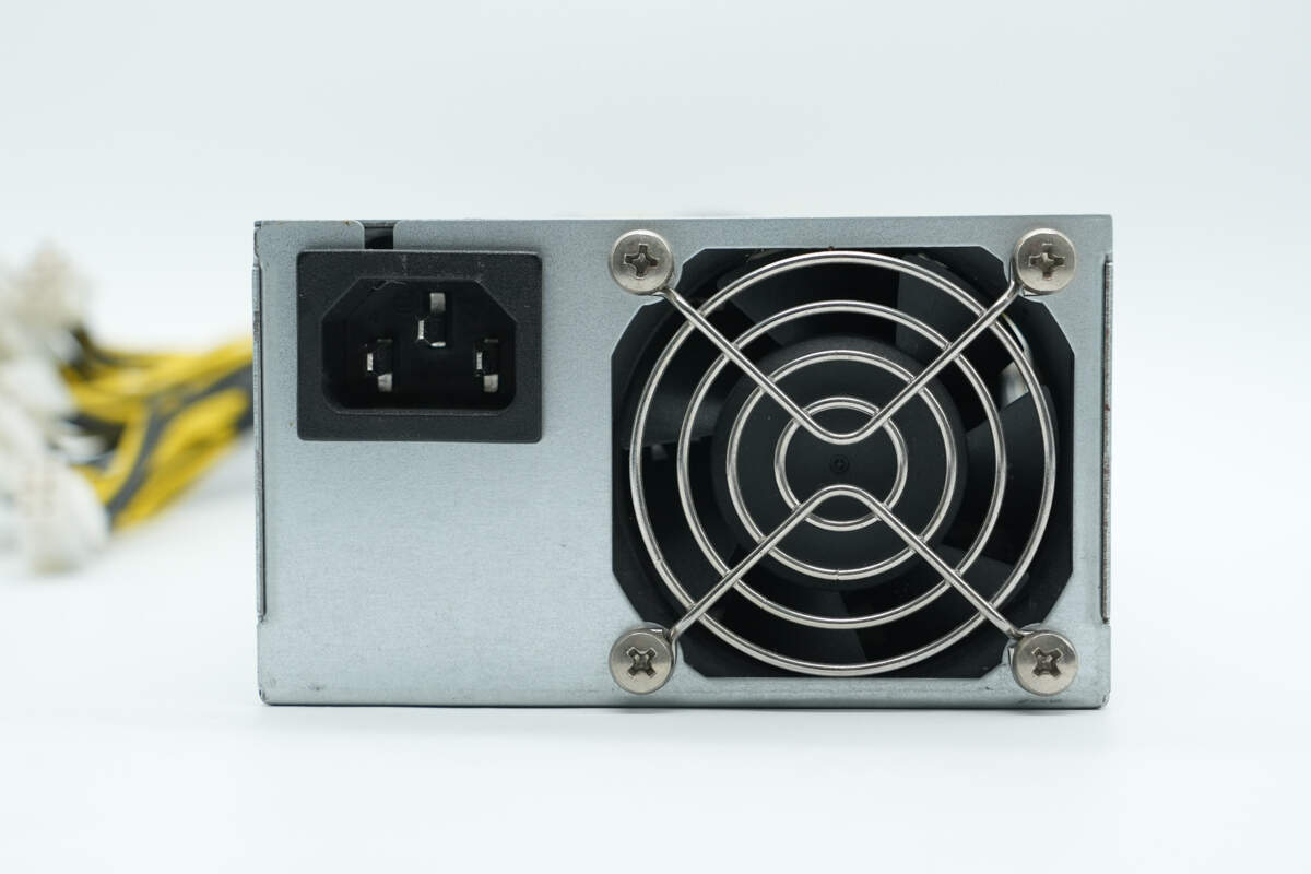
The input side features a C14 power inlet and a cooling fan, which is equipped with a protective grille.
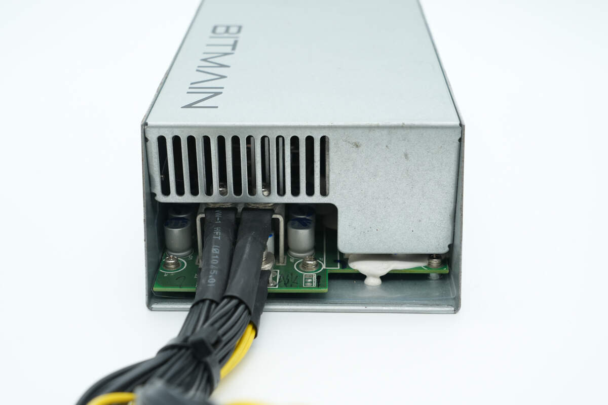
The output side has terminal posts for connecting the output wires, and the PCBA module is secured to the enclosure with screws.
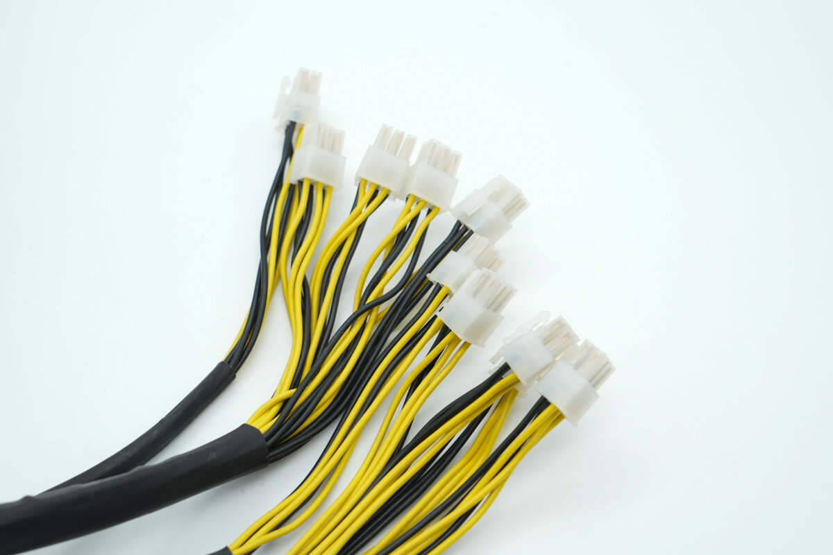
The output cables use 6-pin PCIe connectors.
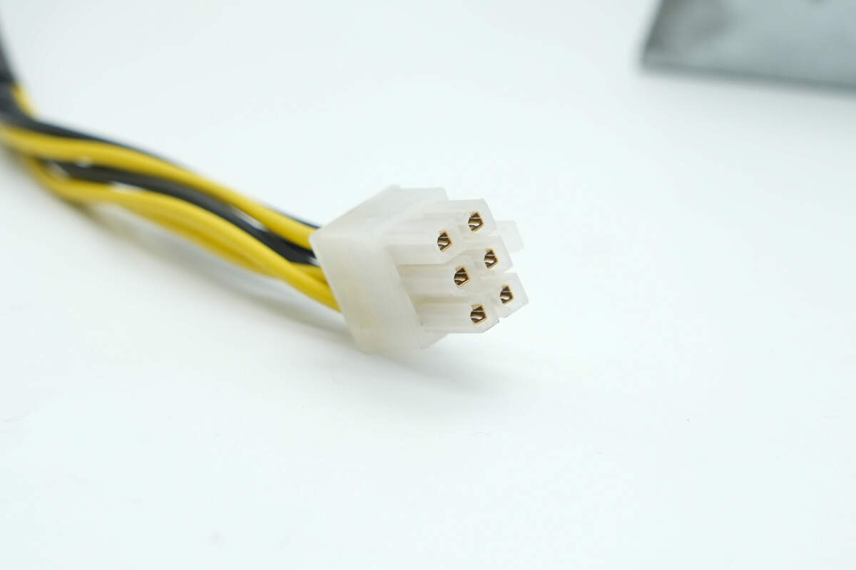
The connectors feature gold-plated spring contacts inside.
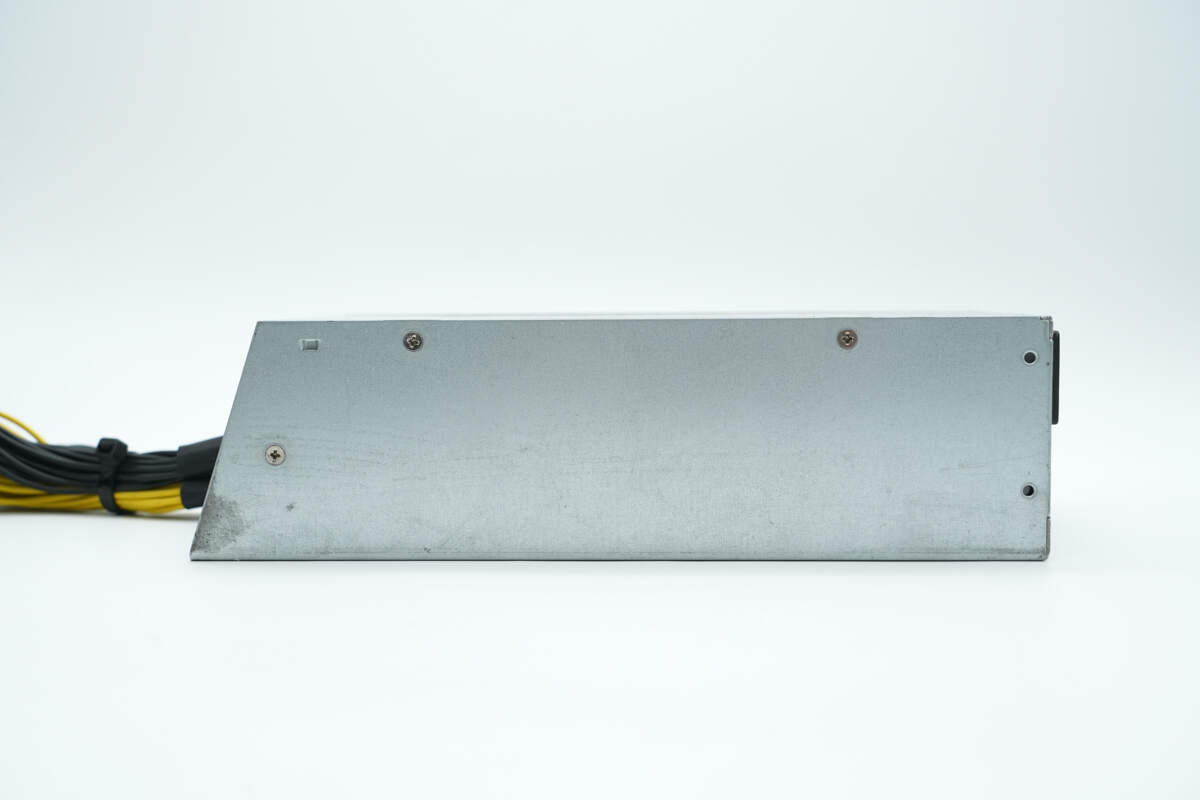
The side is secured with screws.
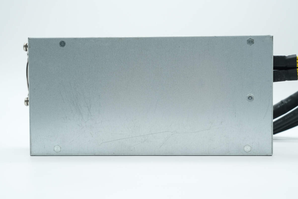
The back is equipped with mounting screw posts.
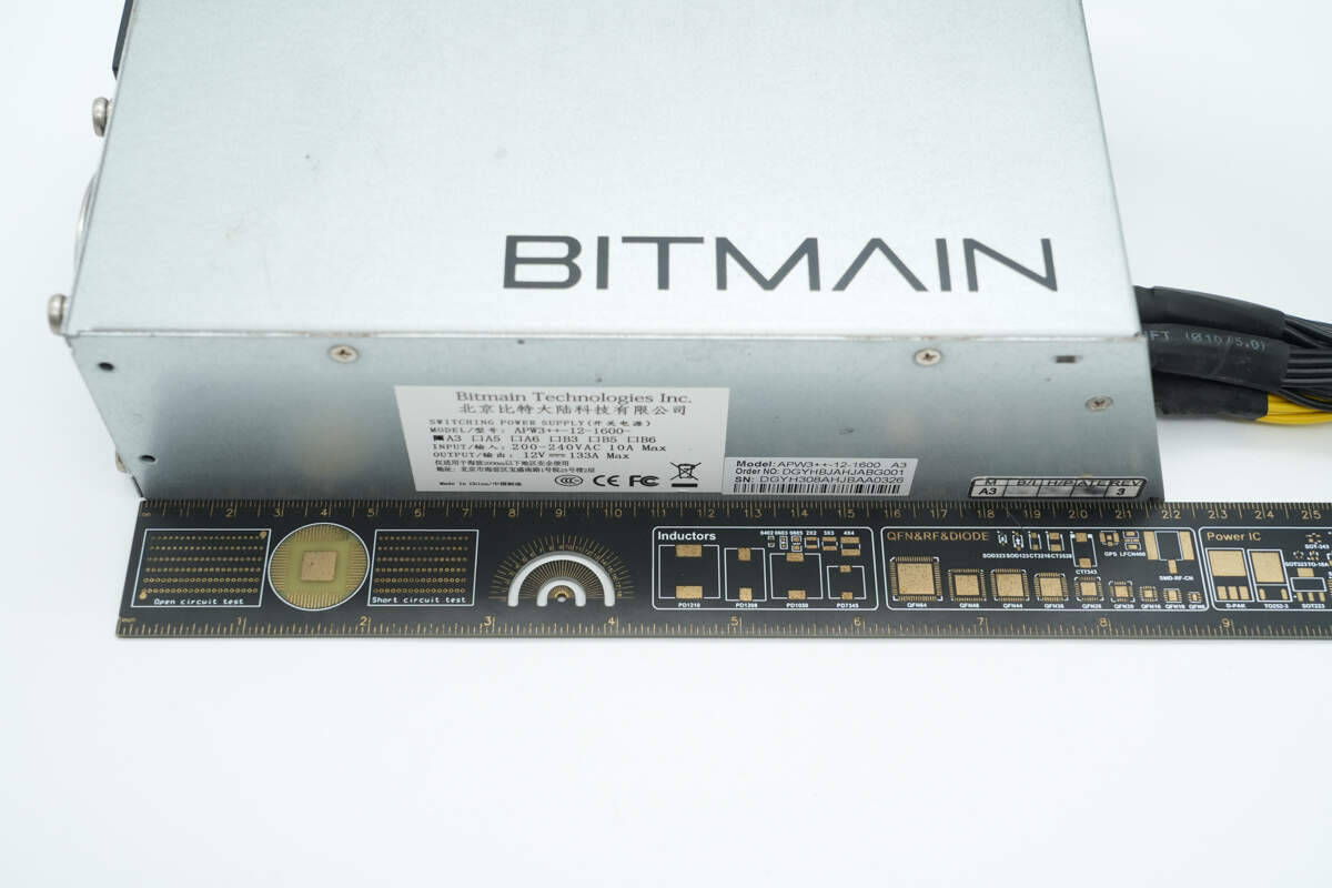
The length of the power supply is about 22 cm (8.66 inches).
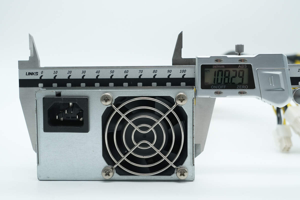
The width is about 108.3 mm (4.26 inches).
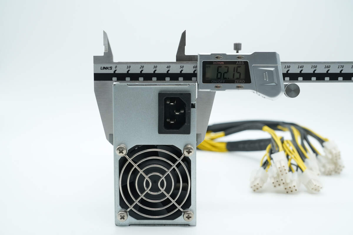
The thickness is about 62.2 mm (2.45 inches).
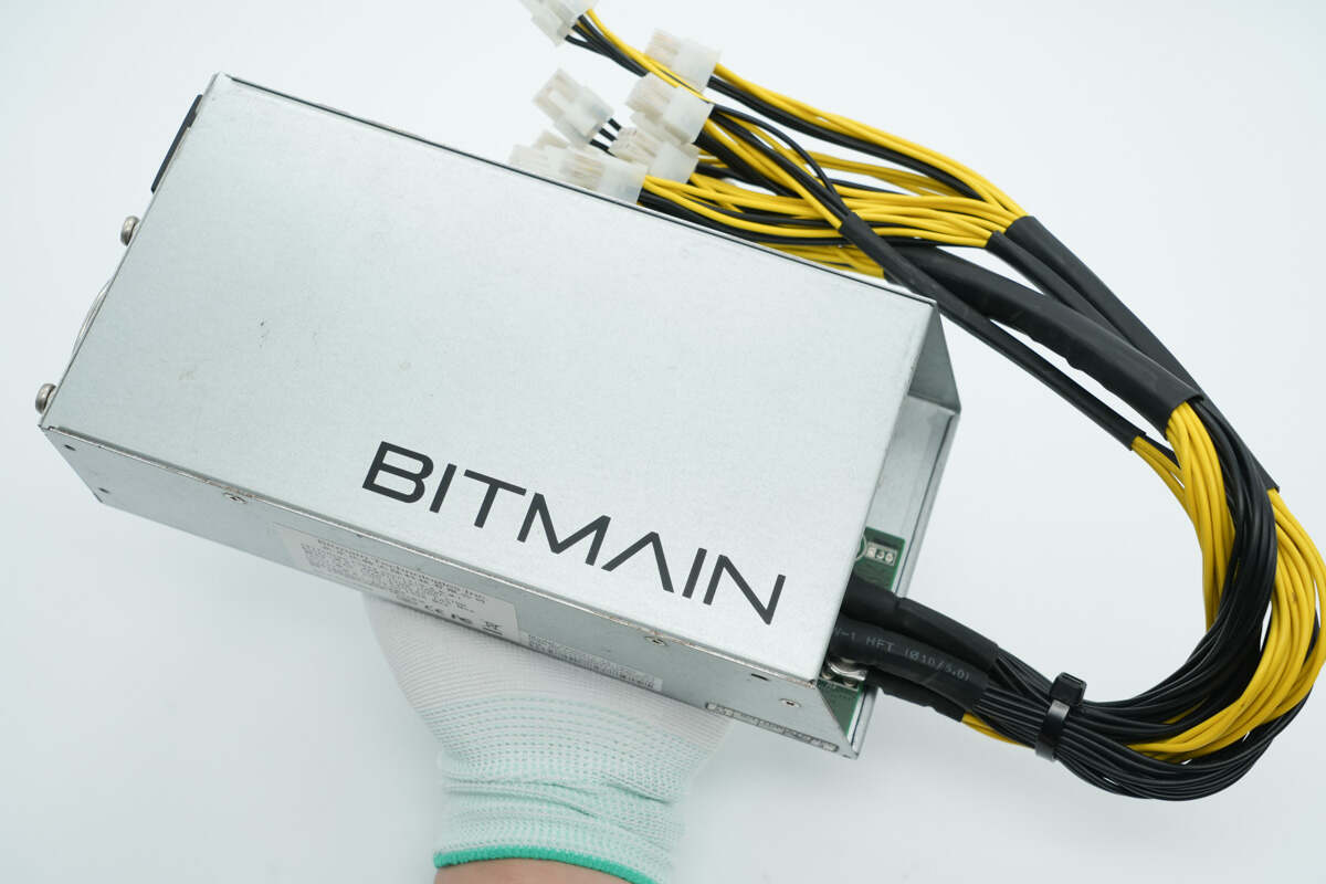
That's how big it is in the hand.
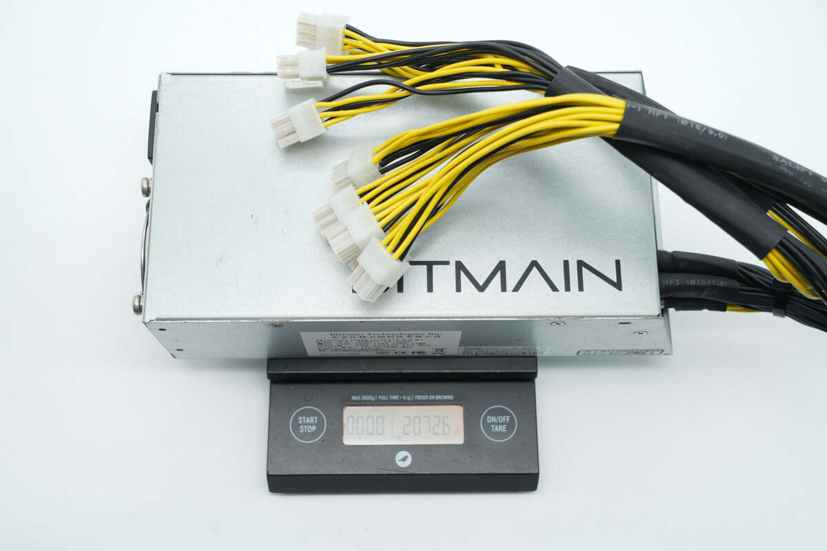
The weight is about 2073 g (4.57 lb).
Teardown
Next, let's take it apart to see its internal components and structure.
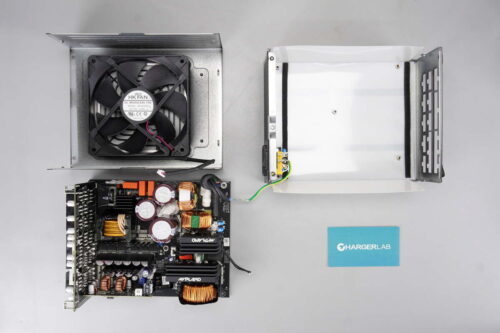
After unscrewing the screws and removing the casing, the inside of the top cover is lined with an insulating Mylar sheet.
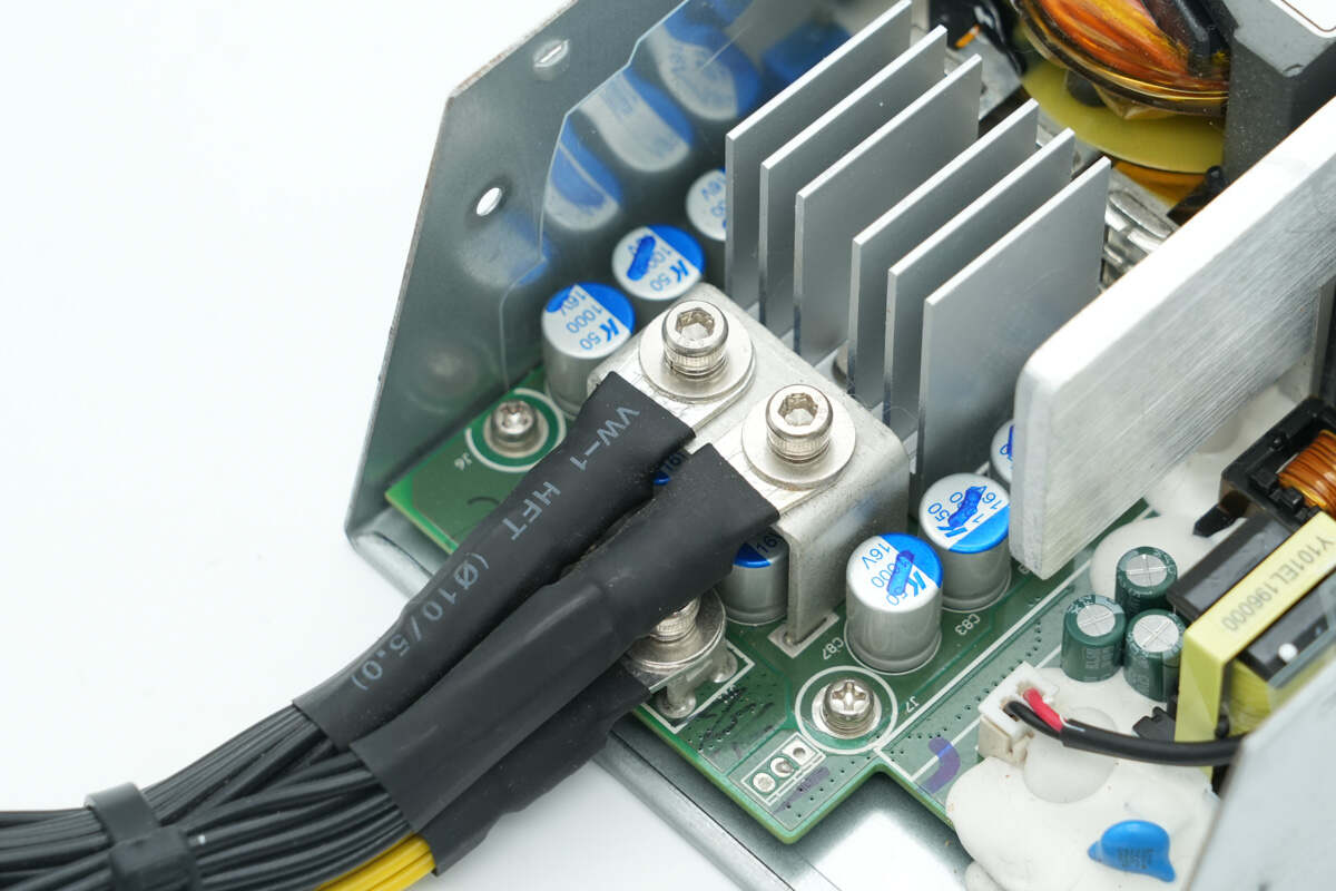
The output wires are secured through terminal posts.
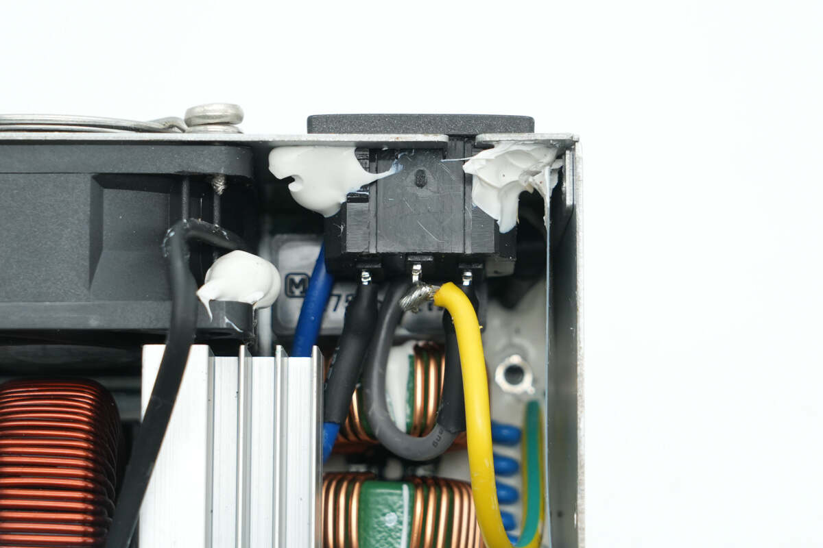
The input socket is reinforced with adhesive, and the wires are soldered for connection.
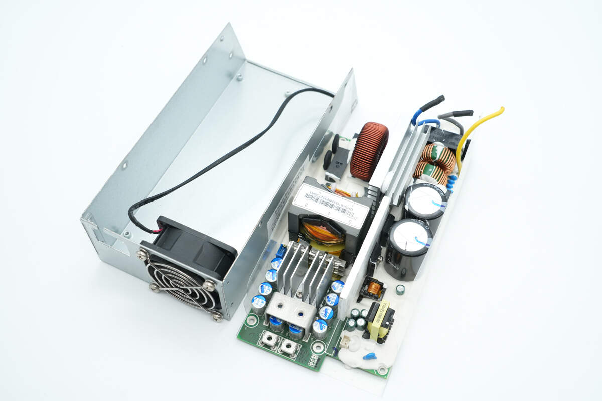
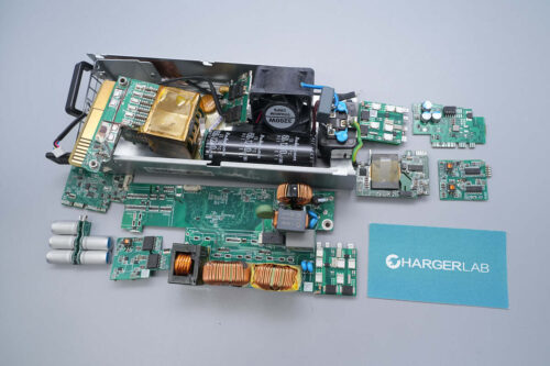
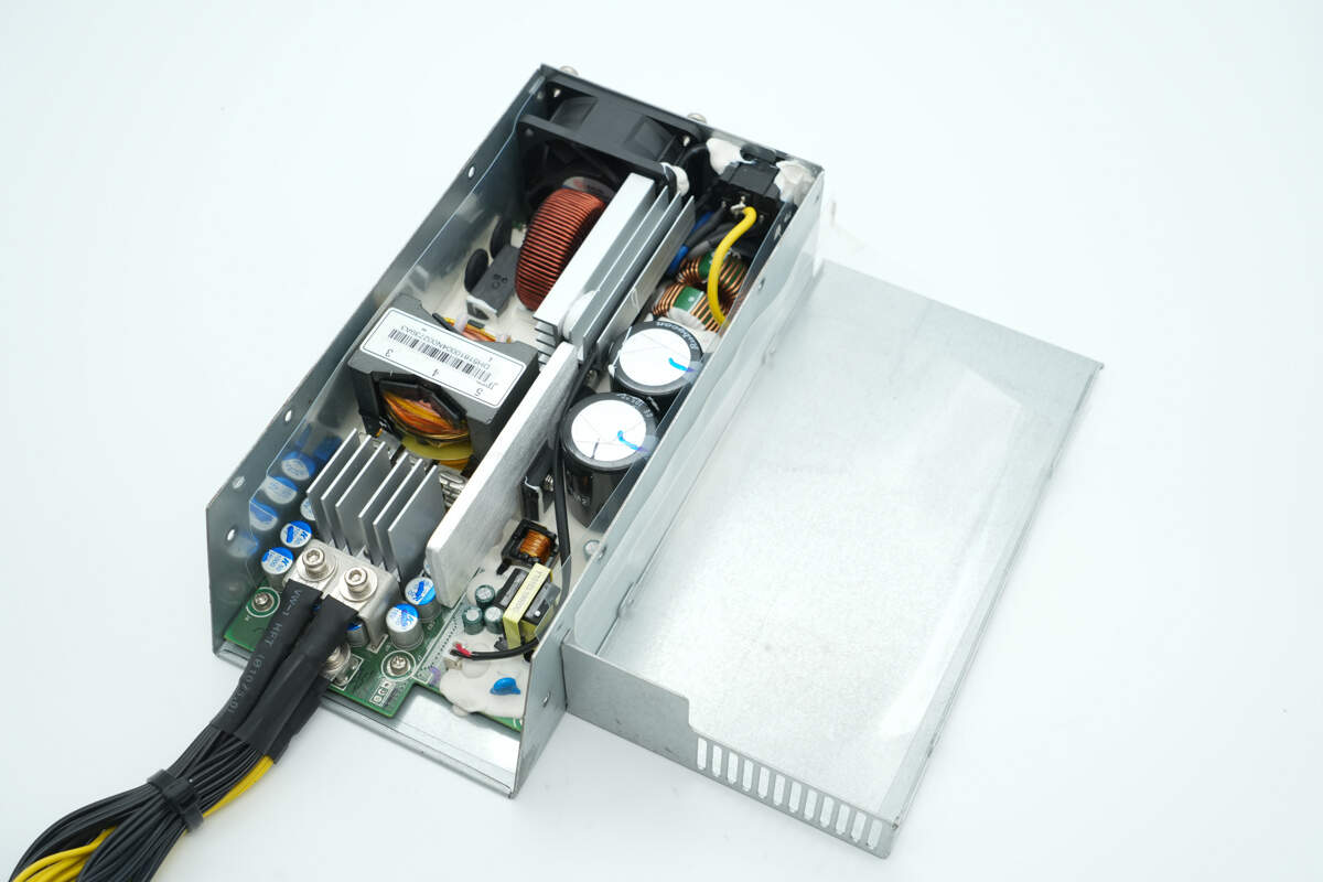
Remove the PCBA module.
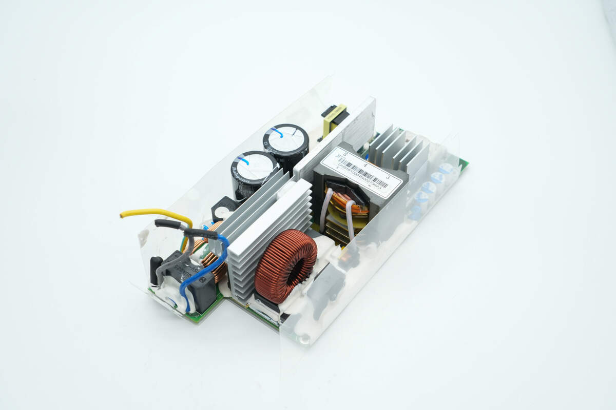
The PCBA module is insulated with a transparent Mylar sheet, and the components are reinforced with adhesive potting.
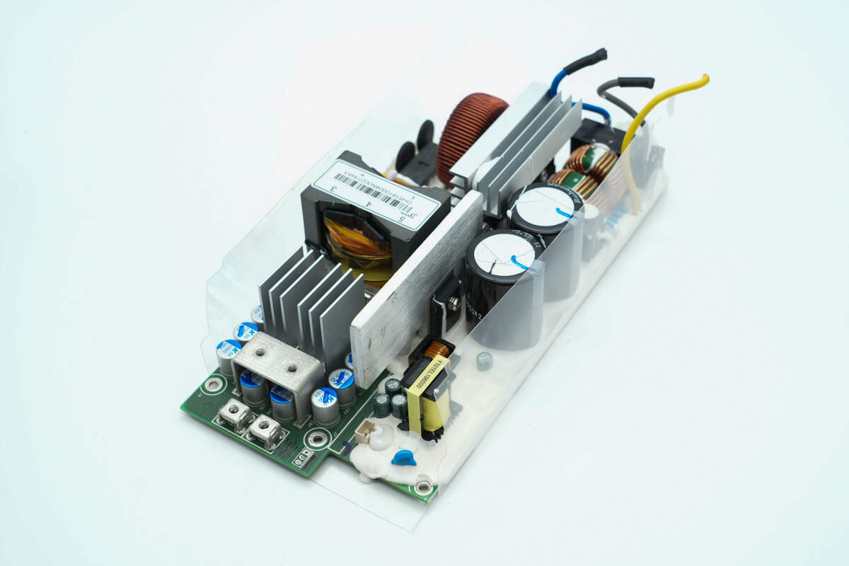
The components on the other side are also reinforced with adhesive potting.
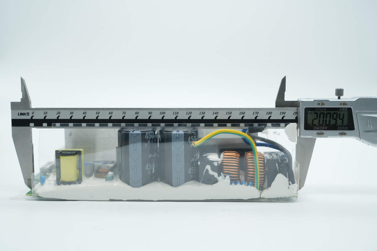
The length of the PCBA module is about 201 mm (7.91 inches).
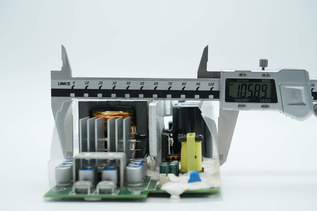
The width is about 105.9 mm (4.17 inches).
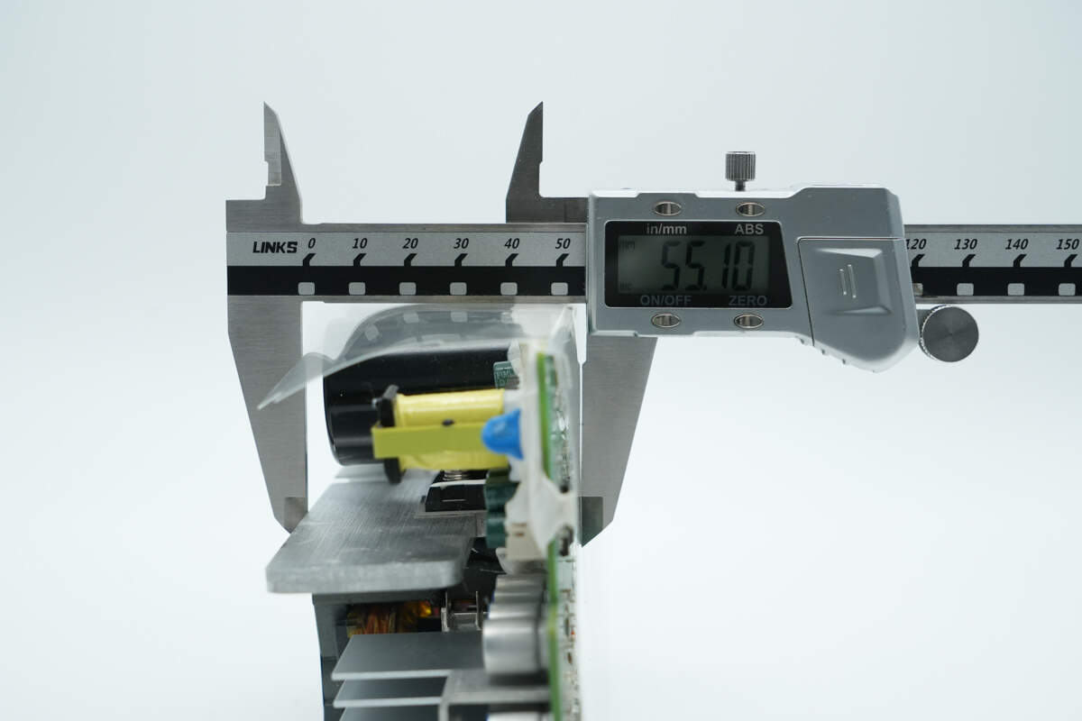
The thickness is about 55.1 mm (2.17 inches).
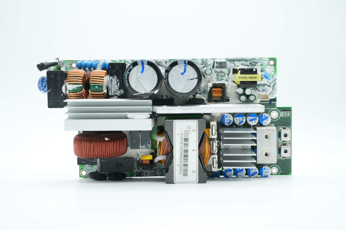
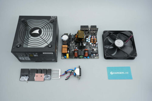
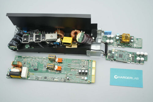
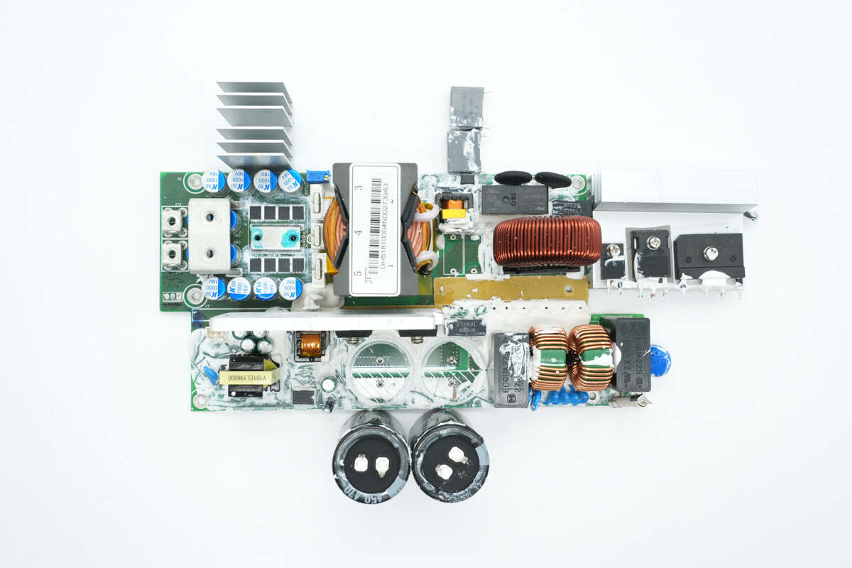
Front side of the PCBA module: The top left corner is the AC input section, equipped with a fuse, varistor, safety X2 capacitors, and common mode chokes. The lower heatsink is used for cooling the bridge rectifier, PFC MOSFET, and PFC rectifier. Below it are the PFC boost inductor, film capacitor, relay, and thermistors.
On the right side are resonant capacitors, a current transformer, transformers, solid capacitors, synchronous rectifiers, and output terminal posts. At the top center are two high-voltage filter capacitors. On the right is the auxiliary power supply. The lower heatsink is used for cooling the LLC MOSFETs.
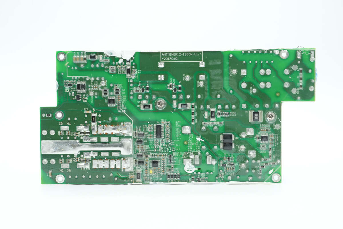
On the back side are the PFC controller, LLC controller, driver, and op-amp. Copper traces for high-current paths are exposed and tinned, with additional copper blocks soldered on to enhance current-carrying capacity. The PCB is also coated with conformal coating for protection.
By disassembling the components and examining the PCBA module, it is observed that the power supply adopts a PFC combined with an LLC topology for output. It uses an Onsemi PFC controller paired with an Infineon MOSFET and a ROHM silicon carbide diode. The LLC stage is controlled by a CHAMPION LLC controller, which drives Toshiba MOSFETs through an isolation transformer. The synchronous rectifiers are supplied by Onsemi, and the standby power supply IC comes from Infineon.
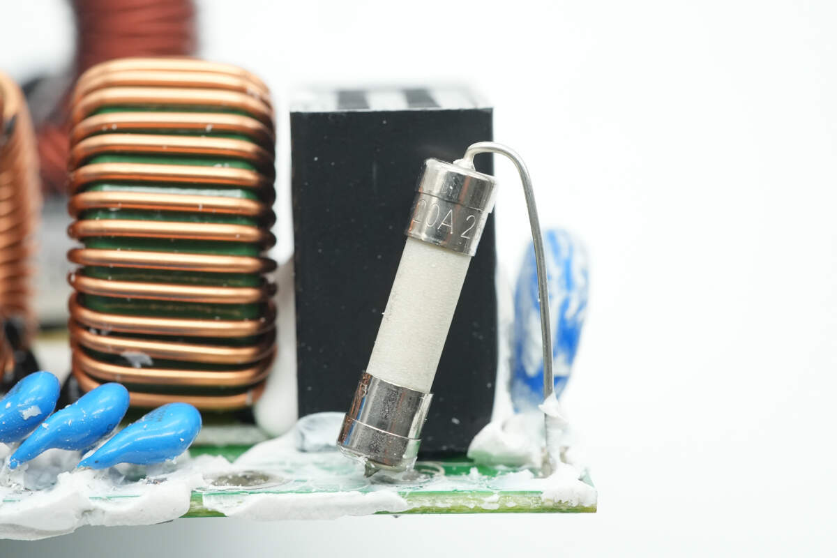
The fuse at the input end is insulated with heat-shrink tubing. 20A 250V.

The varistor is used for input overvoltage protection.
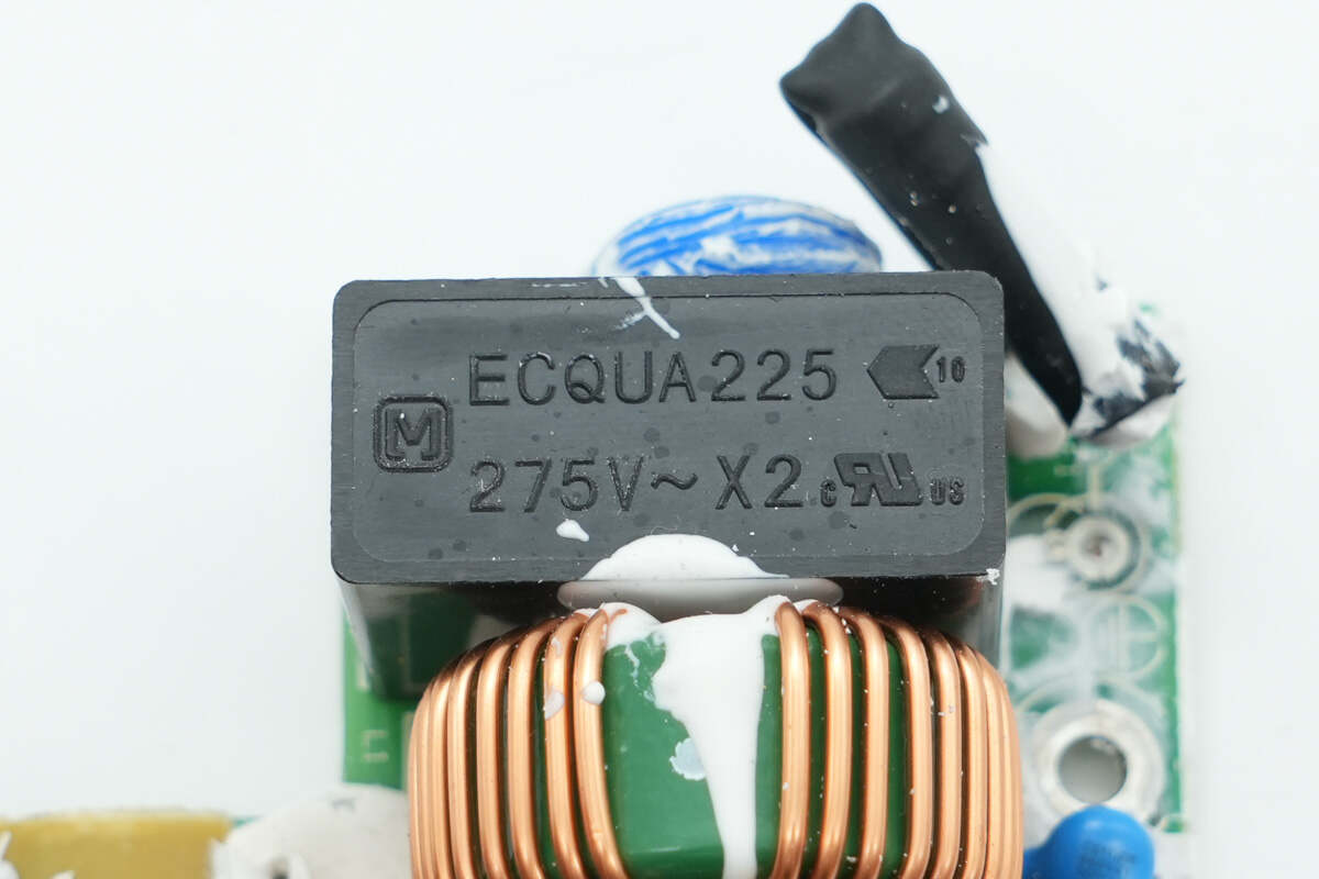
The safety X2 capacitor is from Panasonic. 2.2μF.
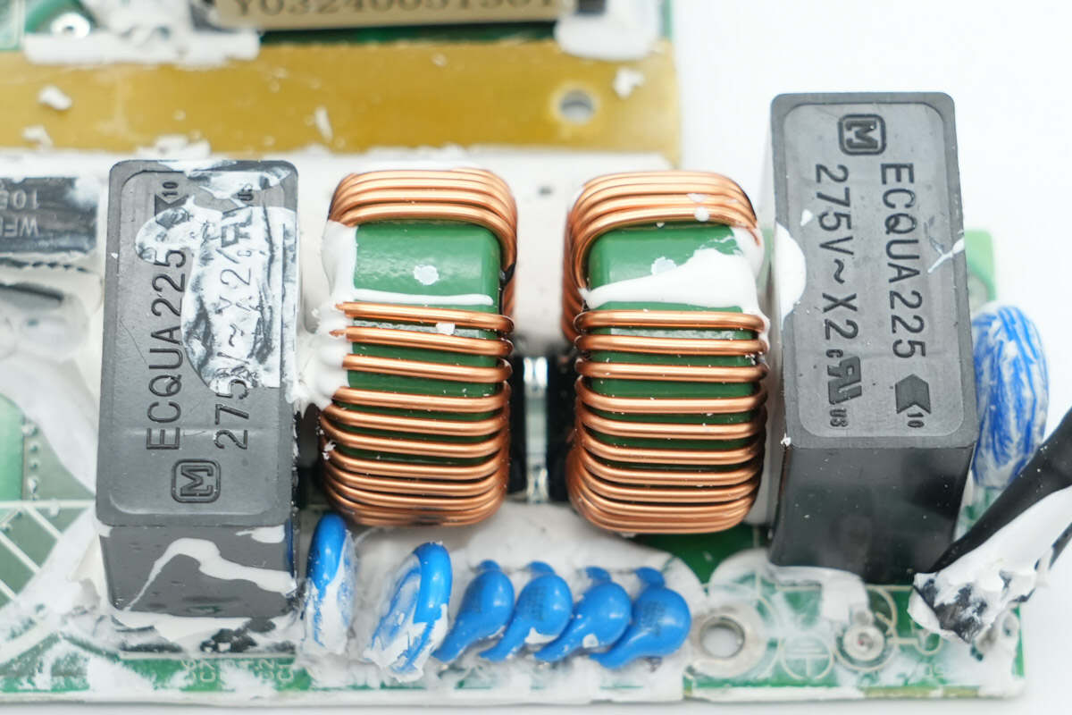
The two common mode chokes are wound with enameled wire.
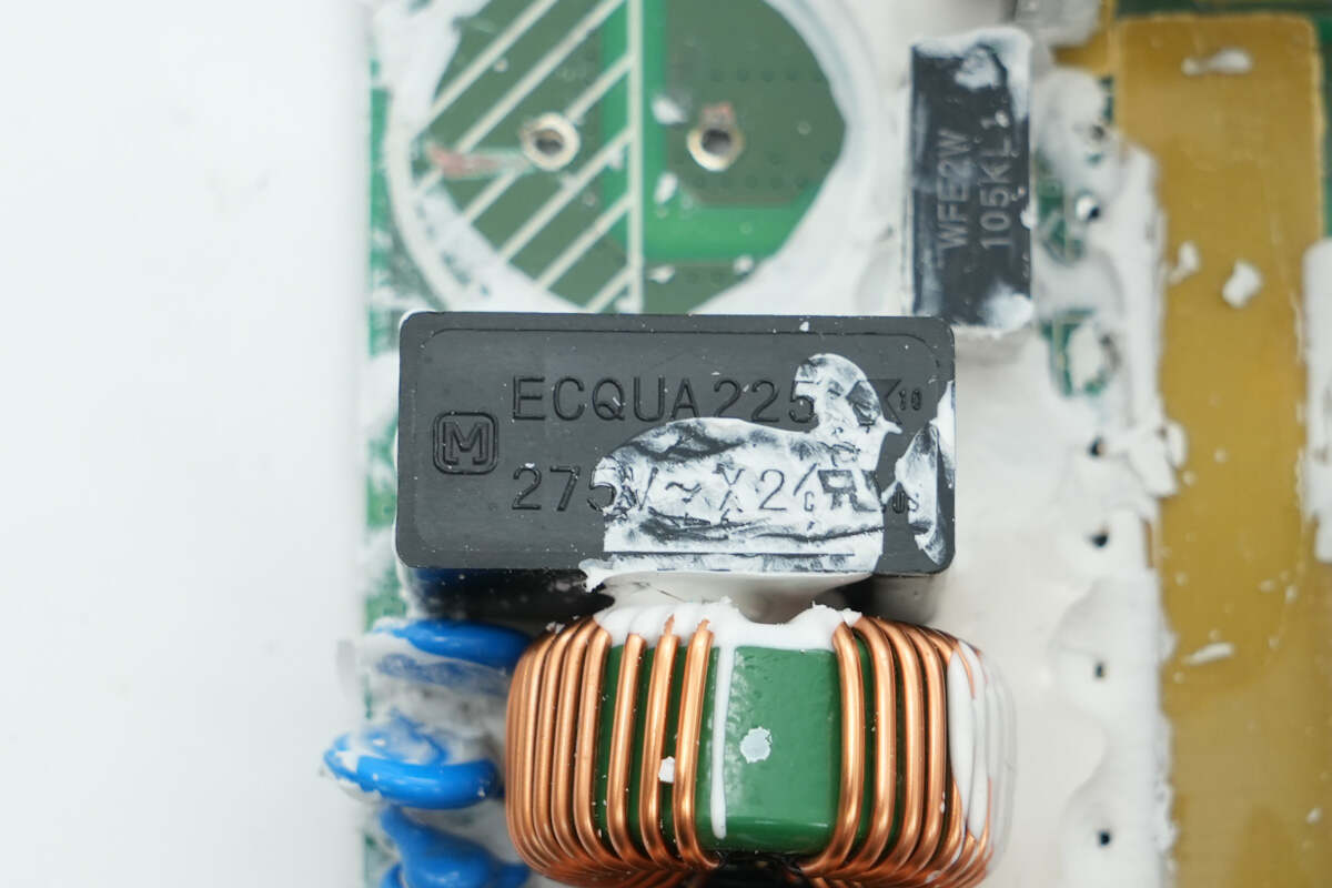
The other safety X2 capacitor has the same specifications.
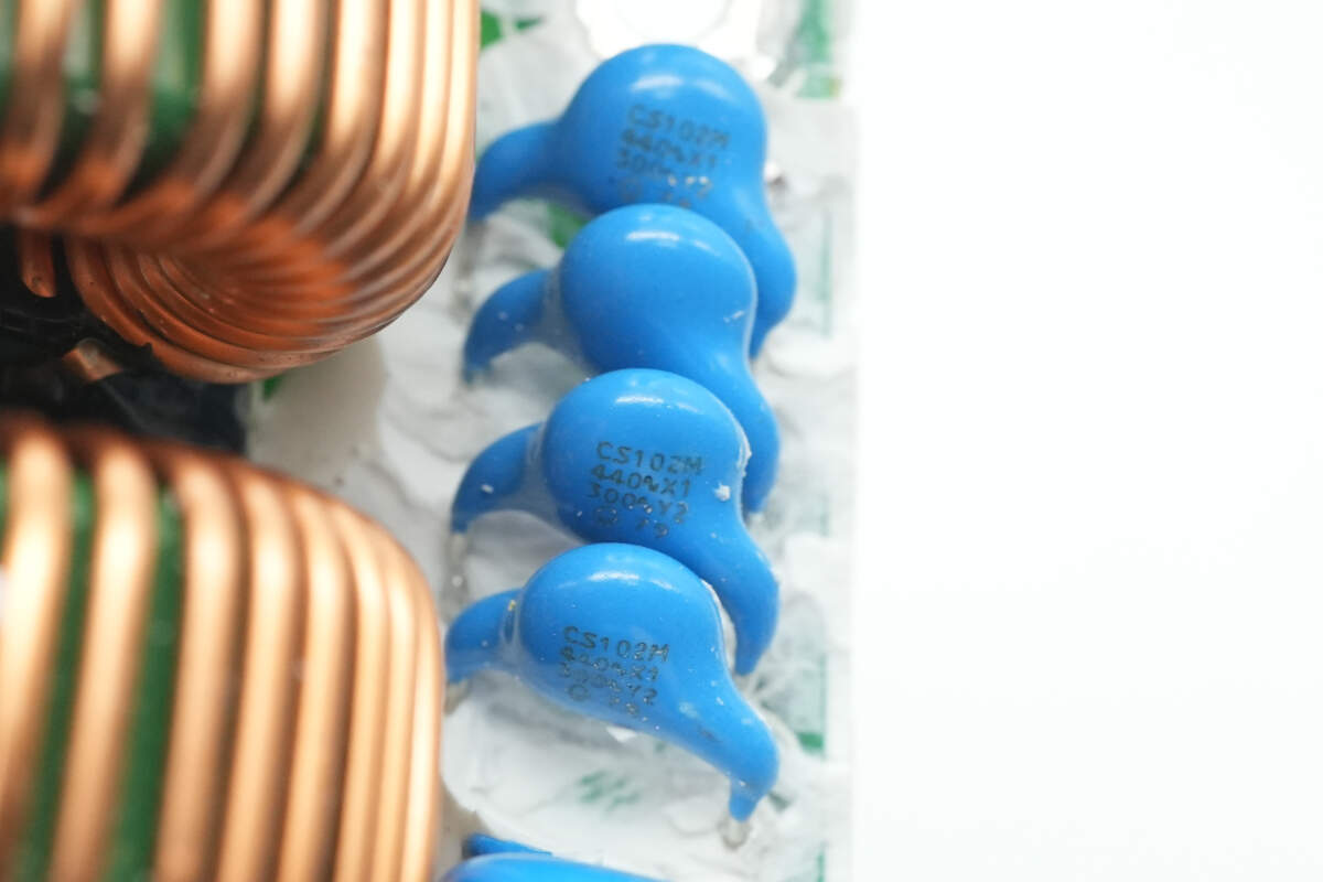
Close-up of the four blue Y capacitors.
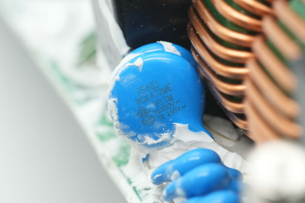
These two blue Y capacitors are from ISND.
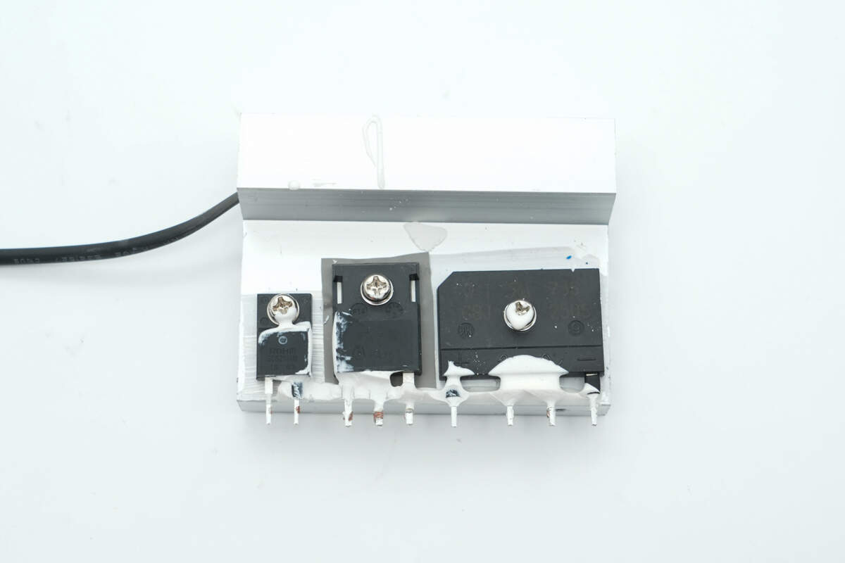
The heatsink is mounted with the bridge rectifier, PFC MOSFET, and PFC rectifier.
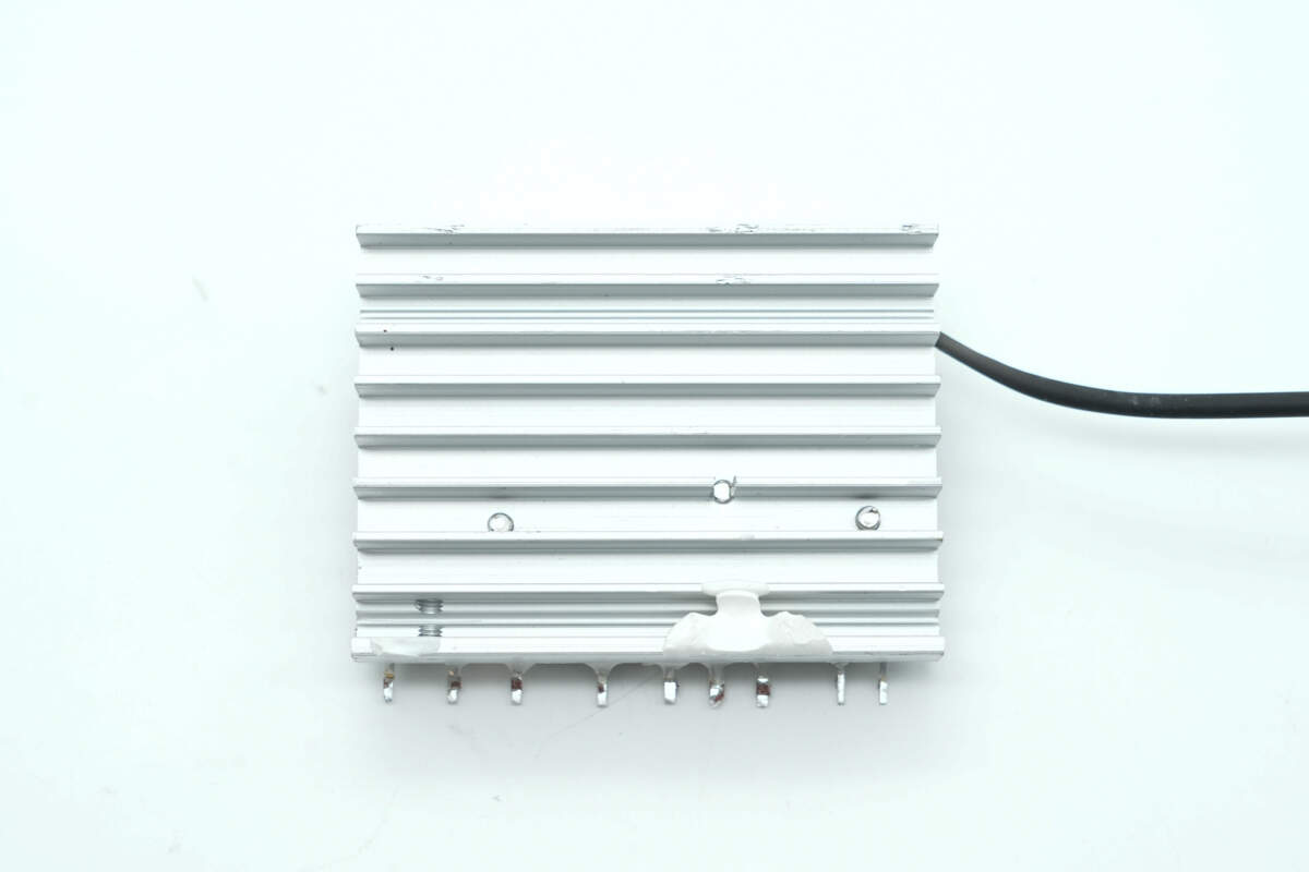
The back features a grille design to increase the heat dissipation area.
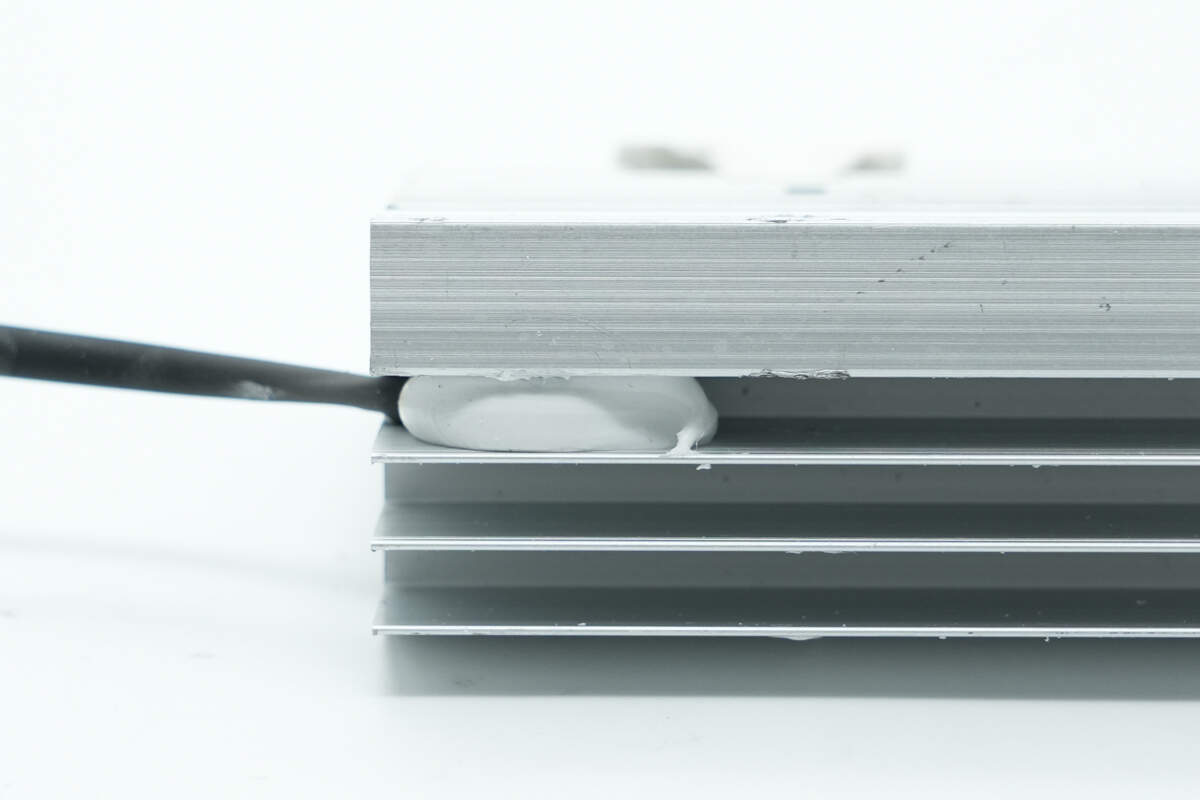
The thermistor is secured with adhesive potting.
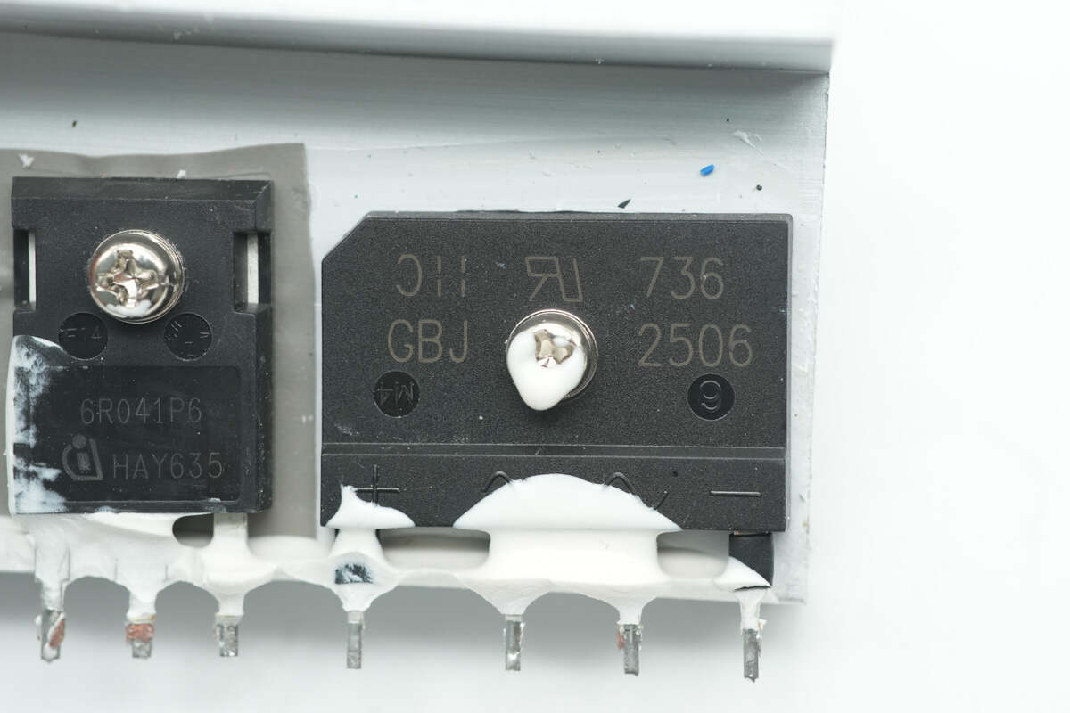
The bridge rectifier is from DIODES, model GBJ2506, rated at 25A 600V, and uses a GBJ package.
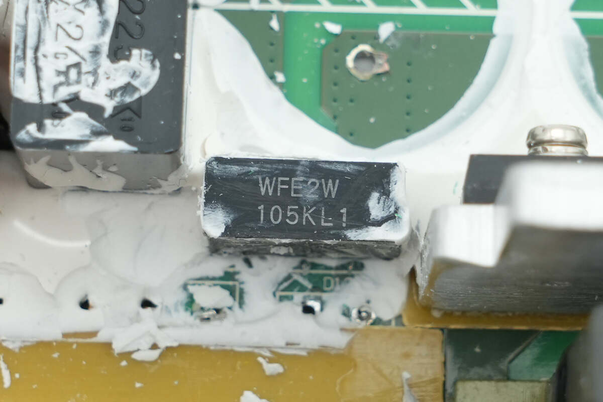
The filter capacitor is from Panasonic, part of the ECWFE series of film capacitors, rated at 450V 1μF.
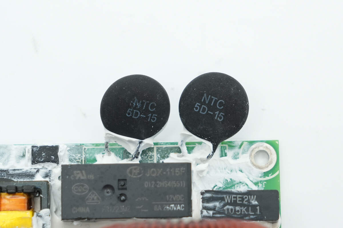
The two thermistors are used to suppress inrush current during power-up.
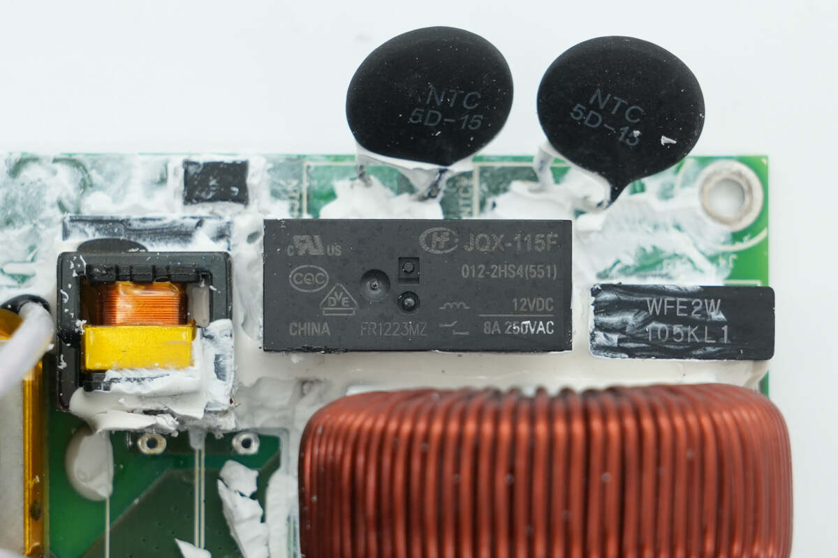
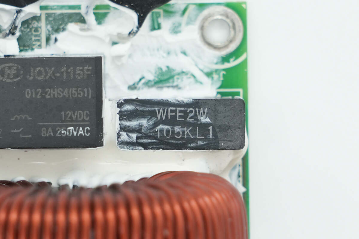
The relay used to short-circuit the thermistors is from HONGFA, model JQX-115F/012-2HS4, with a contact rating of 8A 250V and a coil voltage of 12V.
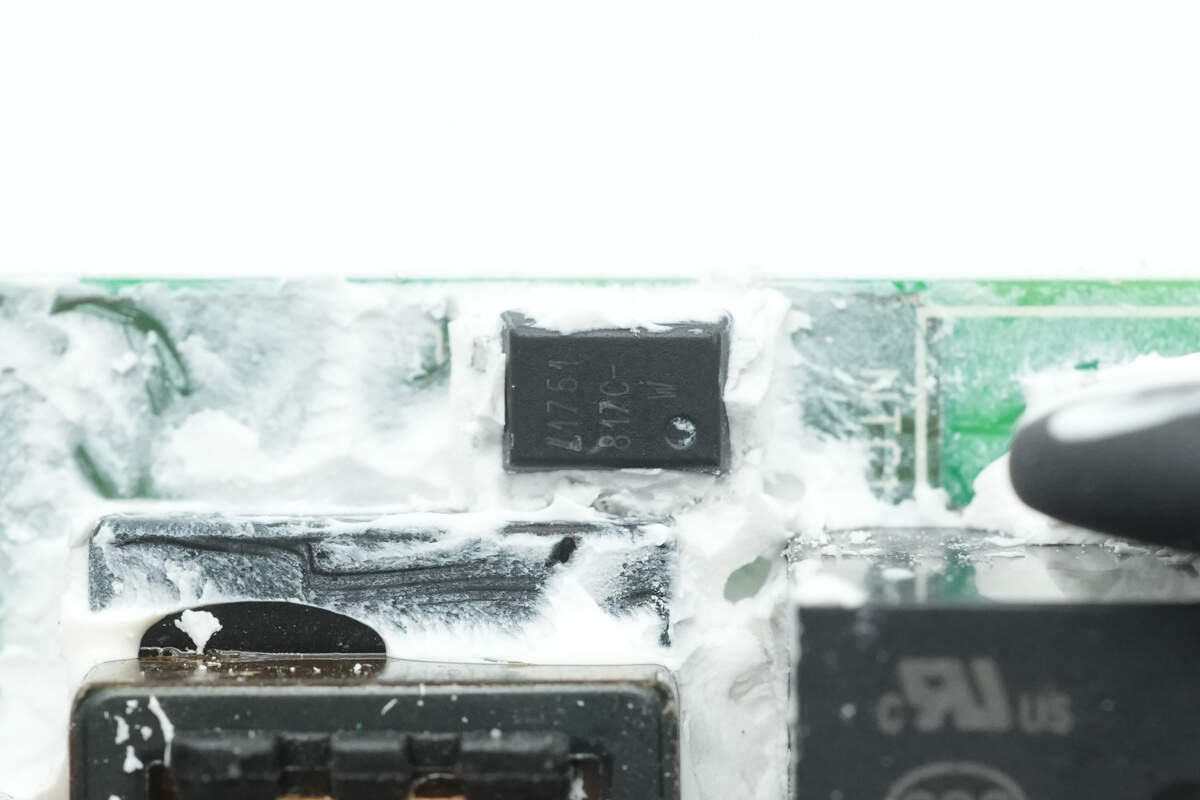
The LTV-817C optocoupler is used to drive the relay.
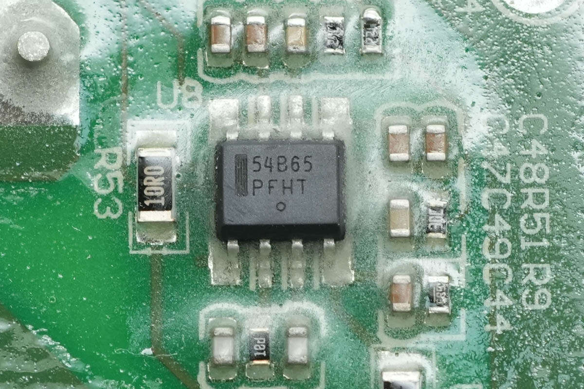
The PFC controller is from Onsemi, marked with 54B65, model NCP1654. It is a continuous conduction mode PFC boost controller operating at a fixed frequency, with conduction time controlled by instantaneous inductor current. It features a simplified external component design, programmable overcurrent protection, and comprehensive protection functions. The device comes in an SO8 package.
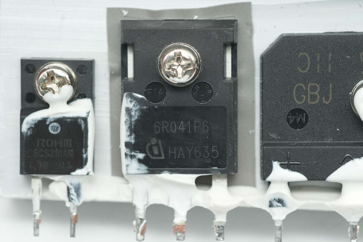
The PFC MOSFET is from Infineon, marked with 6R041P6, model IPW60R041P6. It is an NMOS transistor with a voltage rating of 650V and an on-resistance of 41mΩ, packaged in TO-247.
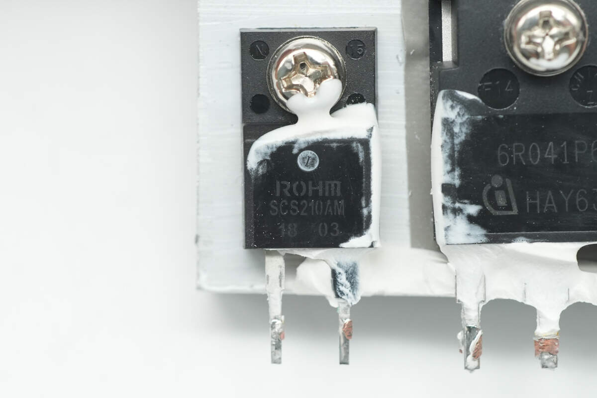
The silicon carbide diode is from ROHM, model SCS210AM, rated at 650V 10A, and uses a TO-220FM-2LGE package.
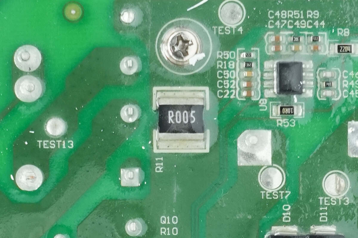
The sampling resistor is used to monitor the MOSFET current. 5mΩ.
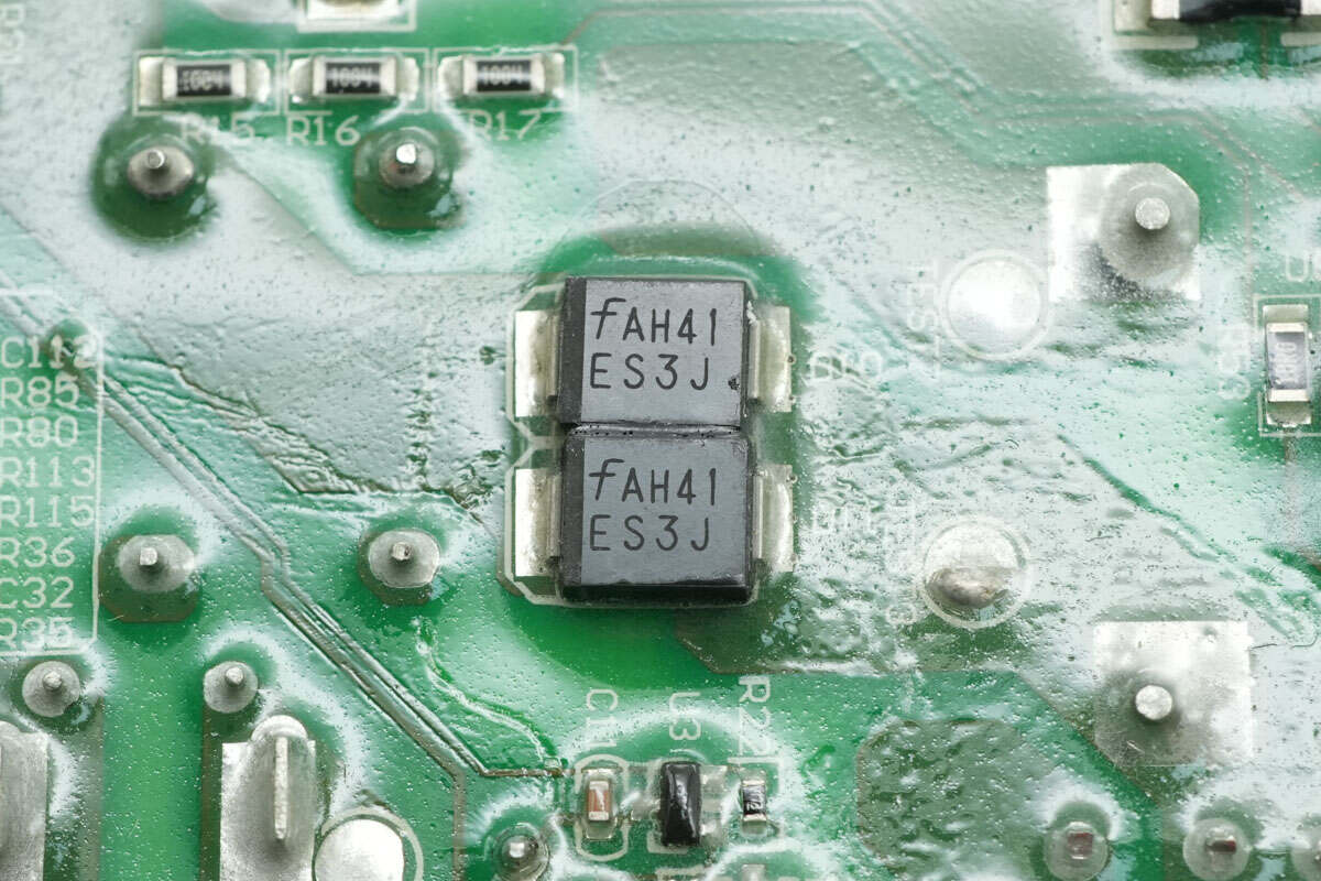
Two ES3J ultra-fast recovery diodes are used for PFC bypass.
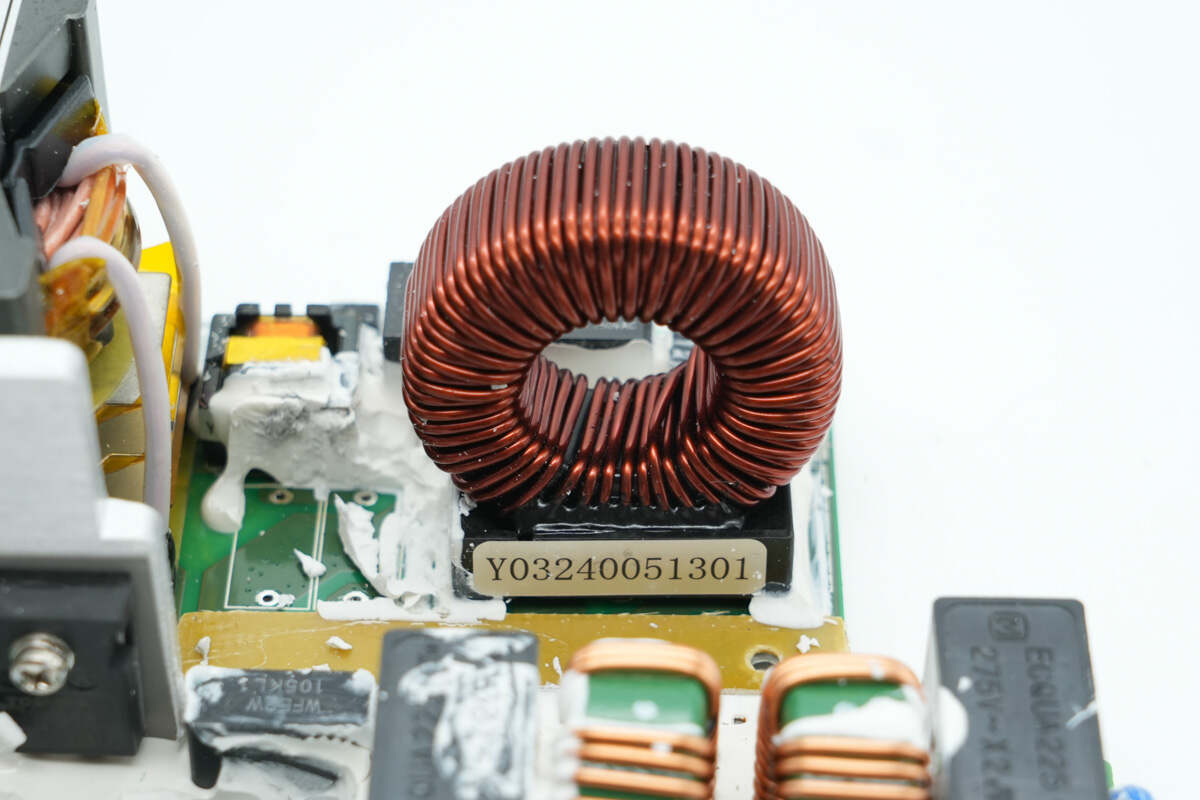
The PFC boost inductor is wound on a ferrite core and features an insulating base support.
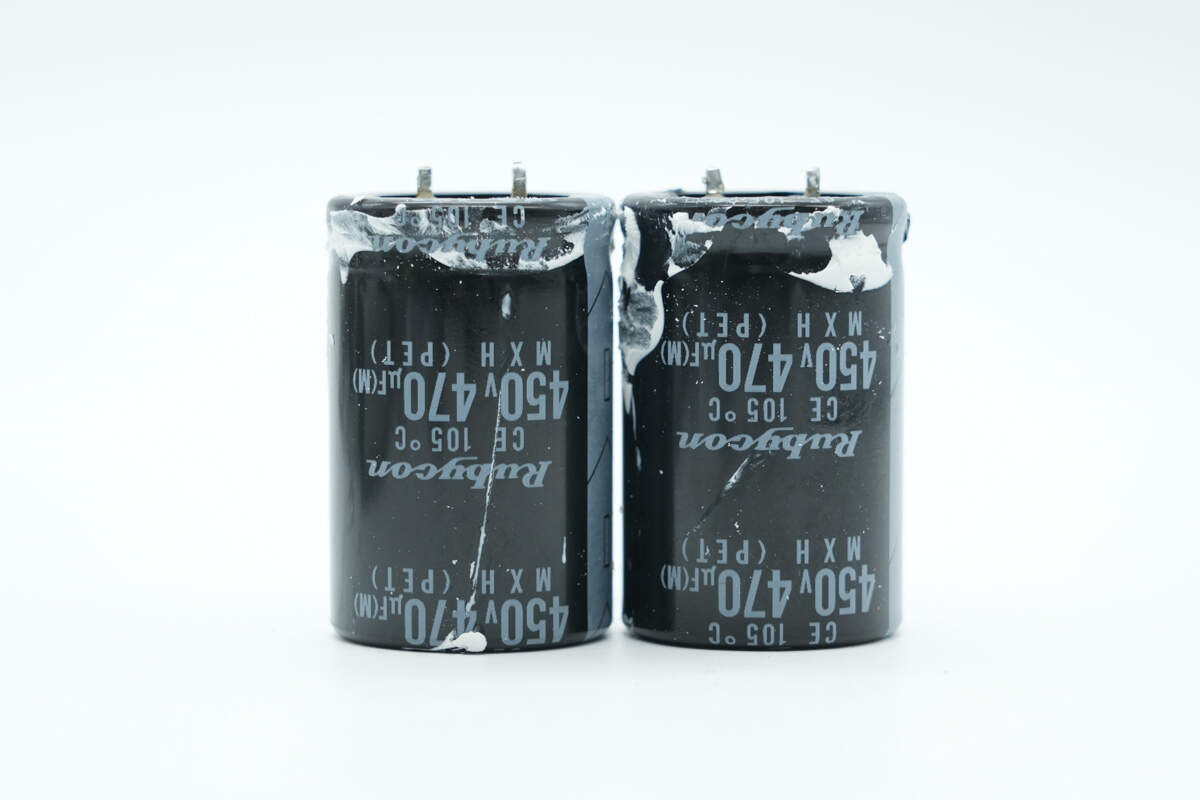
The high-voltage filter capacitors are from Rubycon, MXH series miniature electrolytic capacitors, rated at 450V 470μF, with two units connected in parallel.
The film capacitor is connected in parallel with the high-voltage filter capacitors and is rated at 450V 1μF.
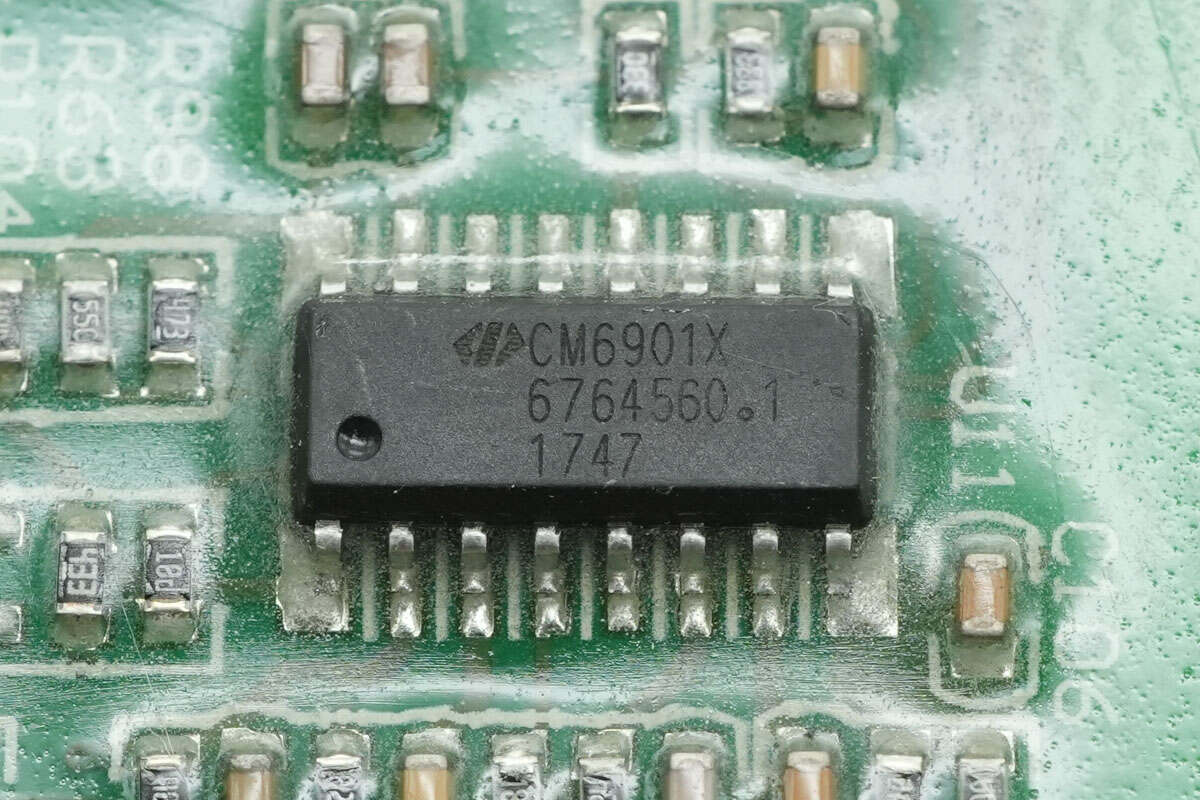
The master control chip is a CHAMPION CM6901, a secondary-side LLC plus synchronous rectification controller. It manages LLC power conversion and secondary-side synchronous rectifier driving, using low-side drivers and an isolation transformer to drive the LLC MOSFETs. It comes in an SOP16 package.
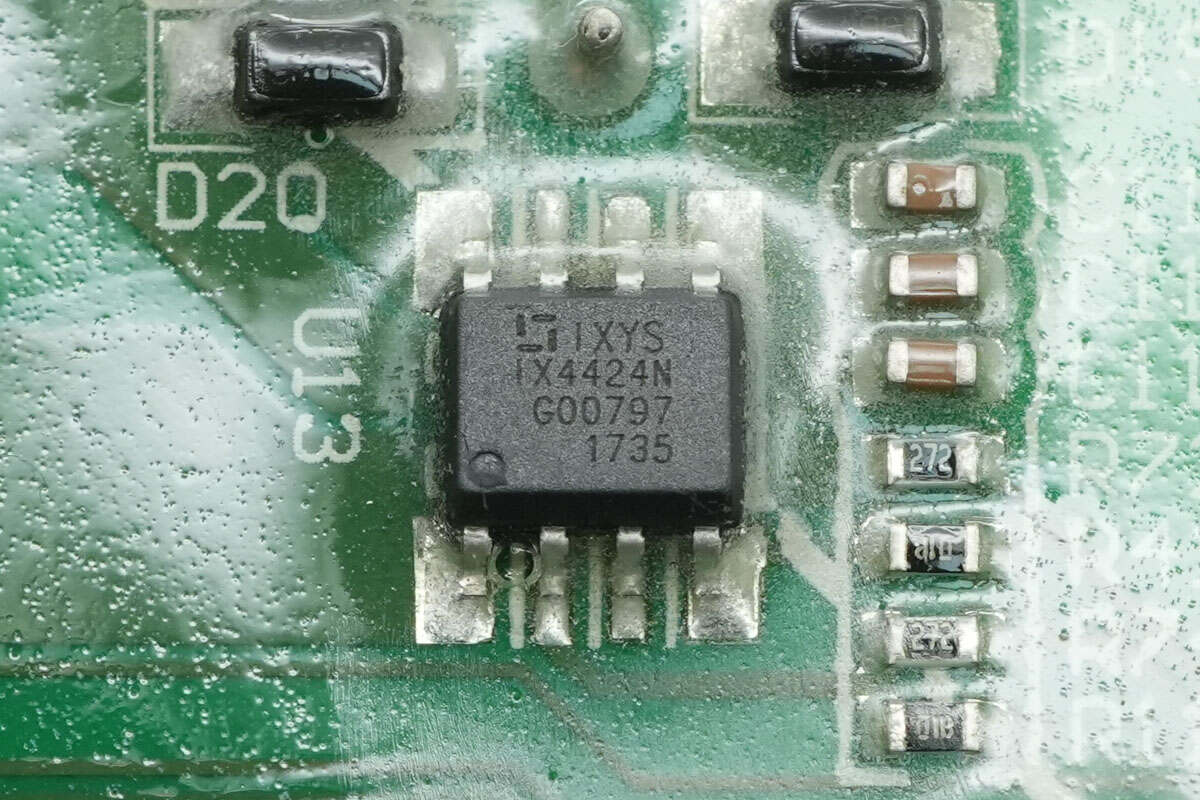
The driver is from Littelfuse, model IX4424N. It is a dual low-side driver with a peak output current of 3A, housed in an SOIC8 package.
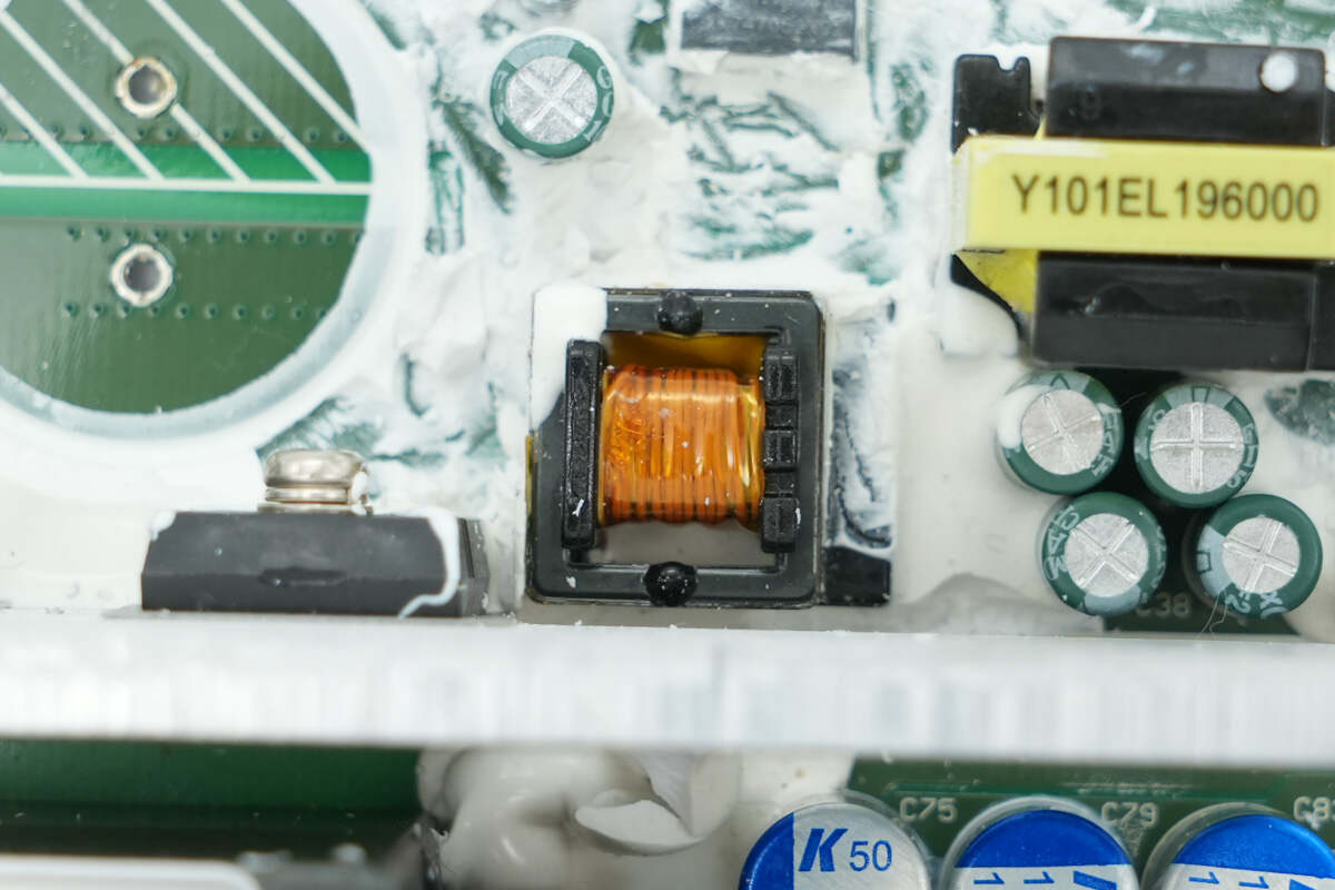
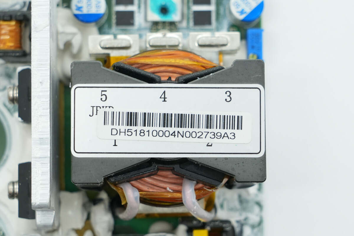
The isolation transformer is used to drive the LLC MOSFETs.
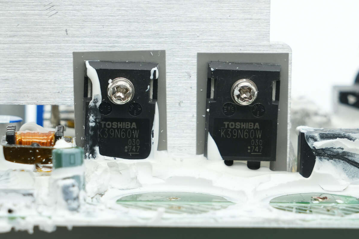
The LLC MOSFETs are from Toshiba, model TK39N60W. They are NMOS transistors rated for 600V with an on-resistance of 55mΩ, housed in TO-247 packages.
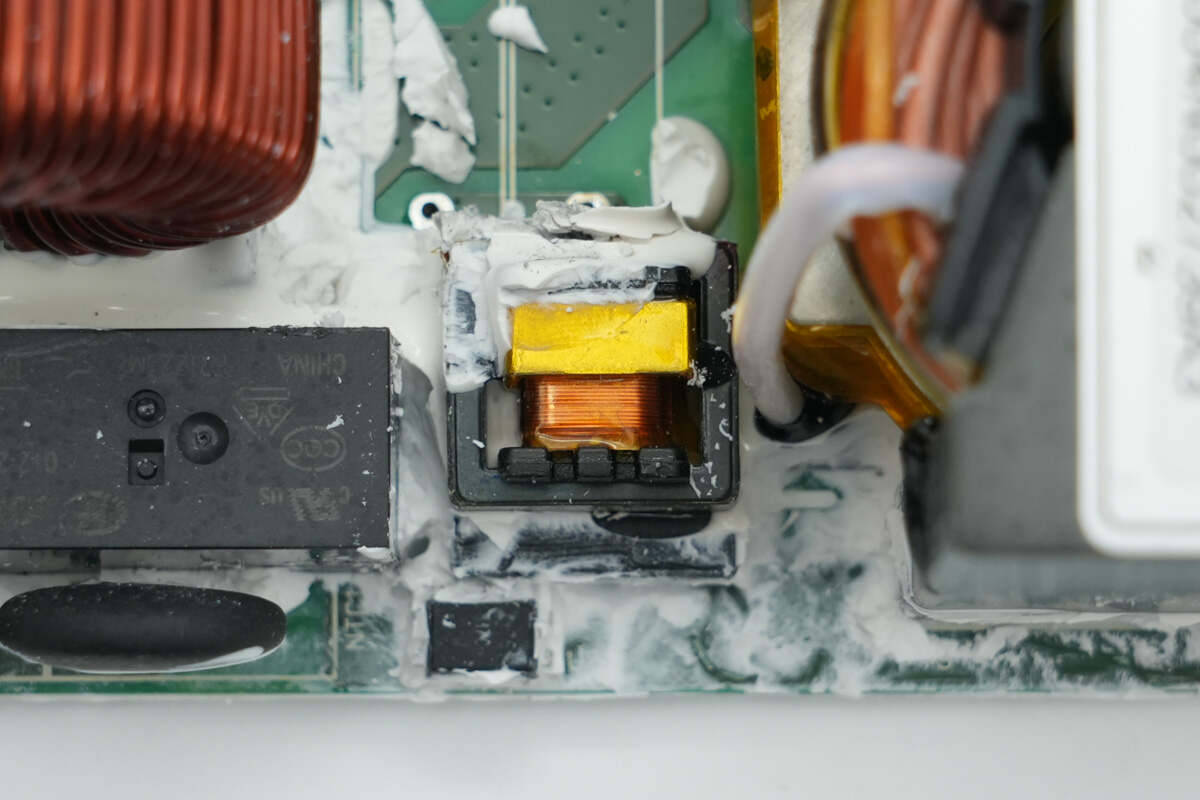
The current transformer is used to monitor the primary current.
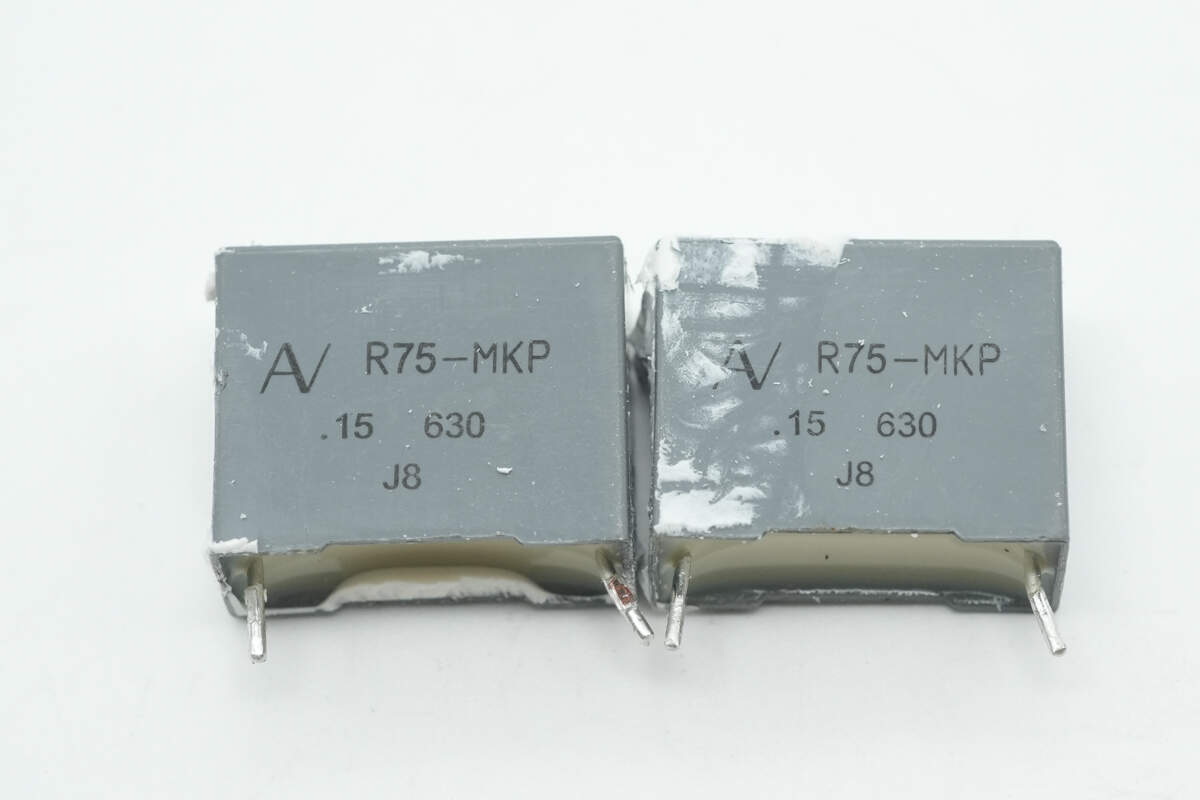
The two resonant capacitors are from KEMET, part of the R75-MKP series, rated at 0.15μF 630V.
The transformer primary winding uses Litz wire, while the secondary winding is connected using soldered copper strips.
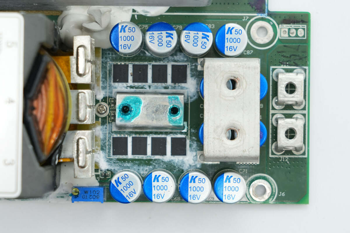
The output stage is equipped with 12 filter capacitors and 8 synchronous rectifiers.
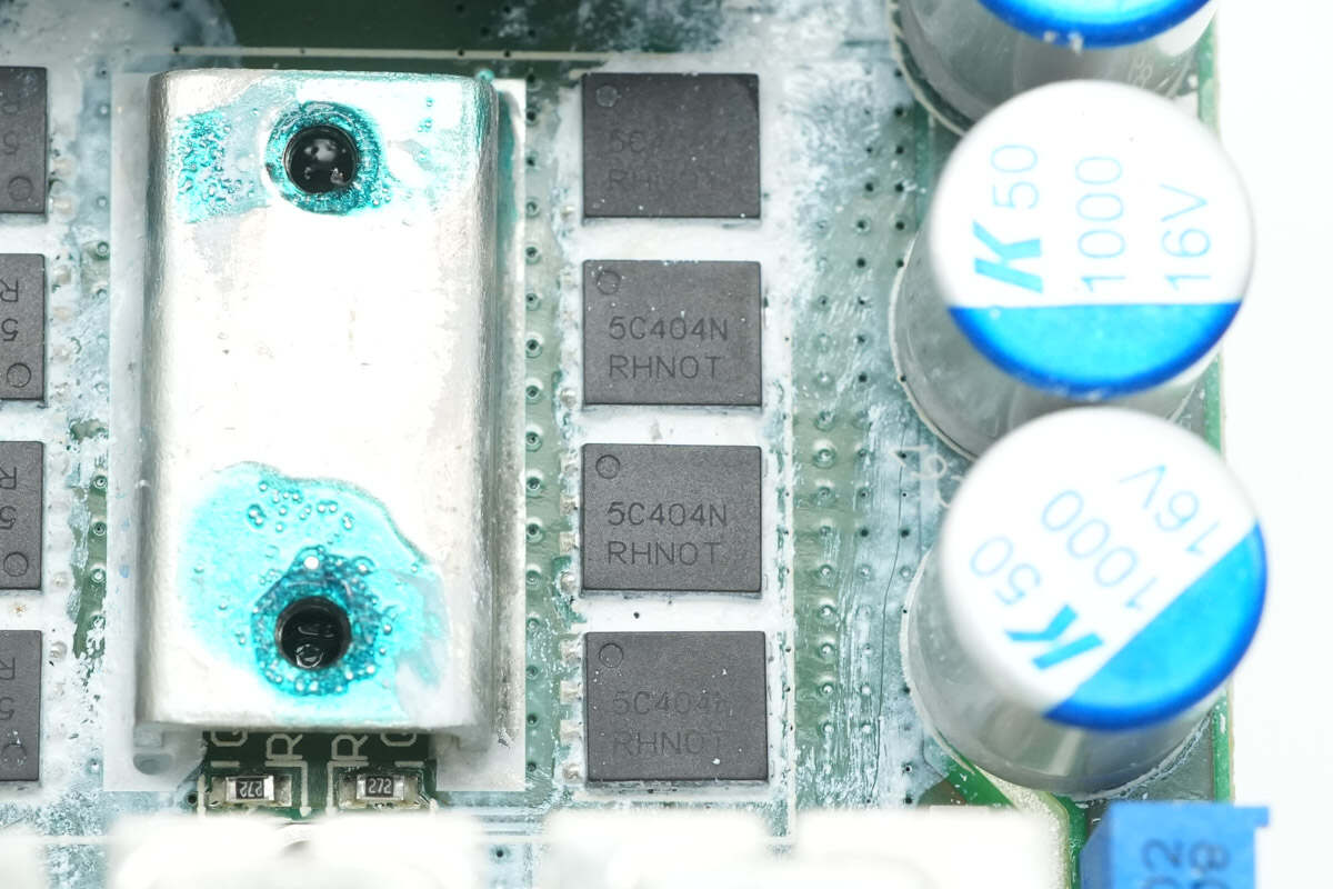
The synchronous rectifiers are from Onsemi, model NVMFS5C404N. They are NMOS transistors rated at 40V with an on-resistance of 0.7mΩ, housed in DFN5 packages.
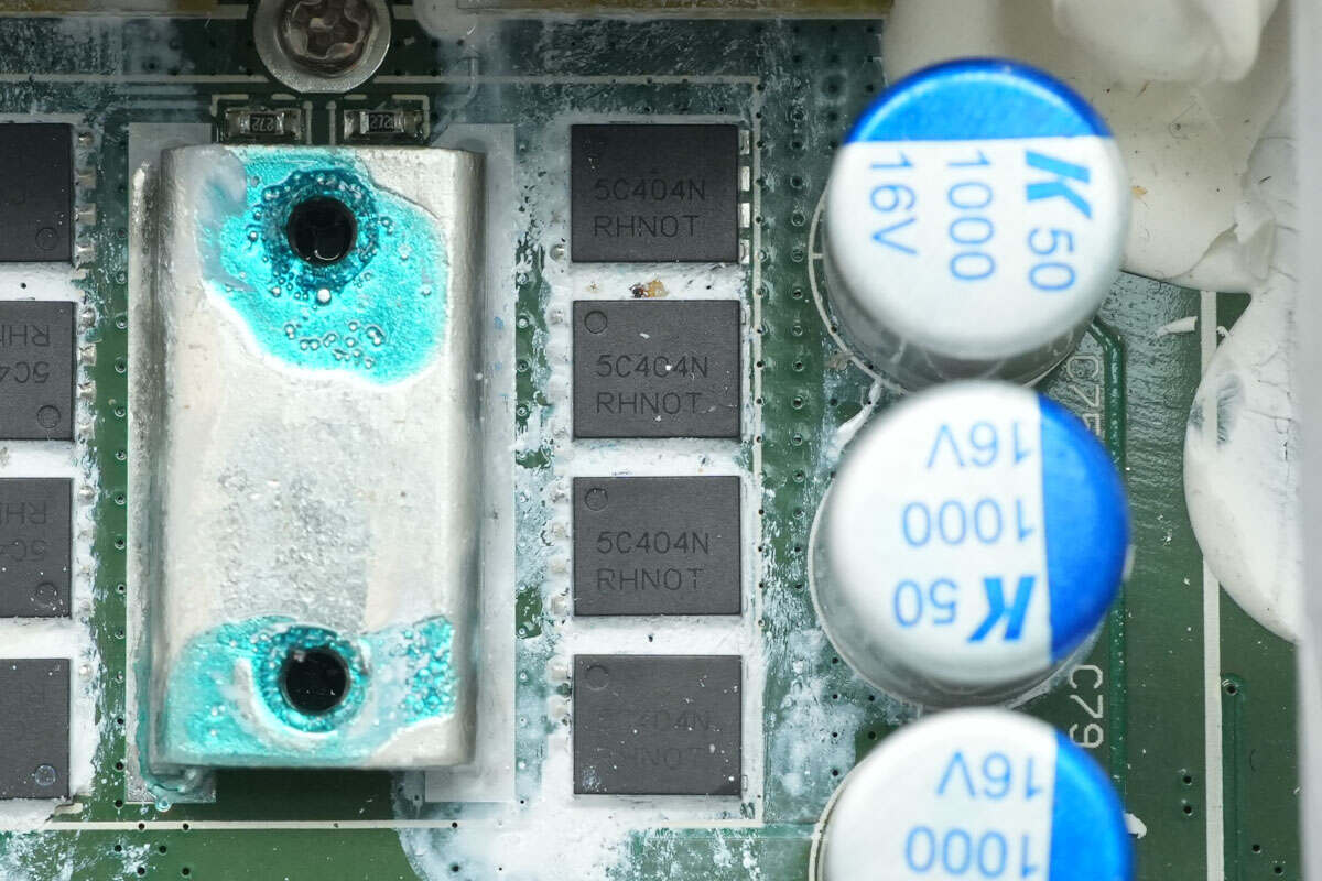
Close-up of four additional synchronous rectifiers of the same model.
The filter capacitors are from KEMET, rated at 1000μF 16V.
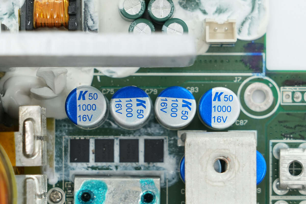
Close-up of four filter capacitors on the other side.
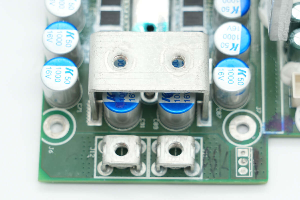
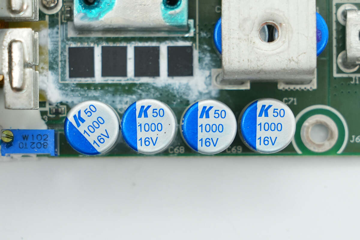
The power supply output terminal posts have the negative terminal posts inside and the positive terminal posts on the outside. Below the internal terminal posts are four filter capacitors.
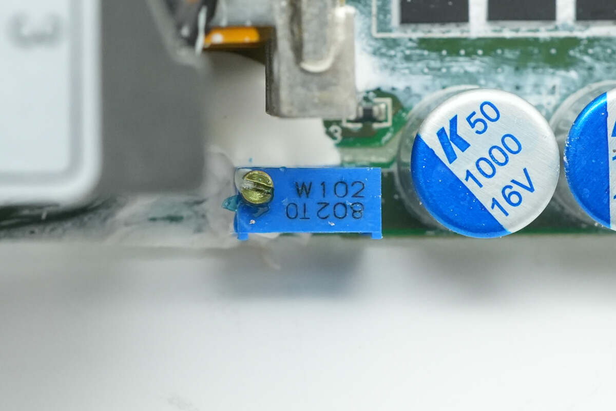
The precision adjustable resistor is used for fine-tuning the output voltage.
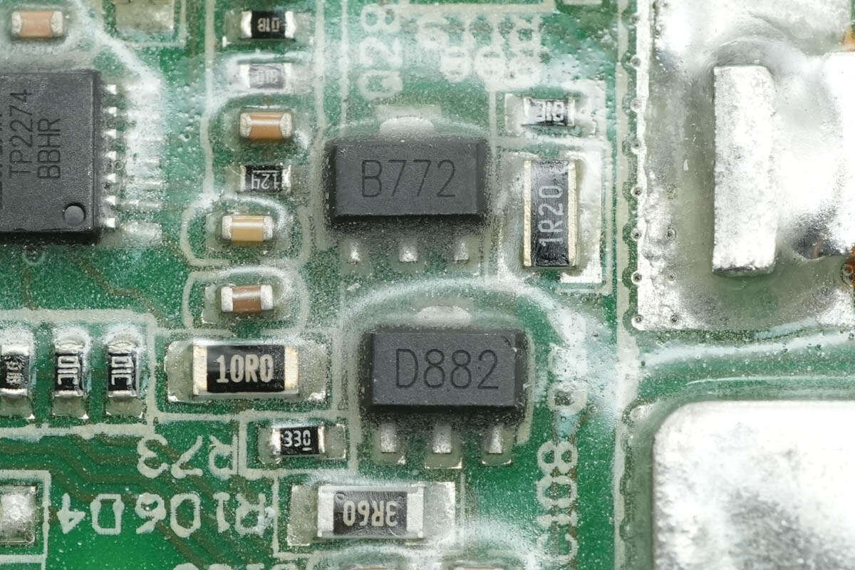
B772 and D882 transistors are used to drive the synchronous rectifiers.
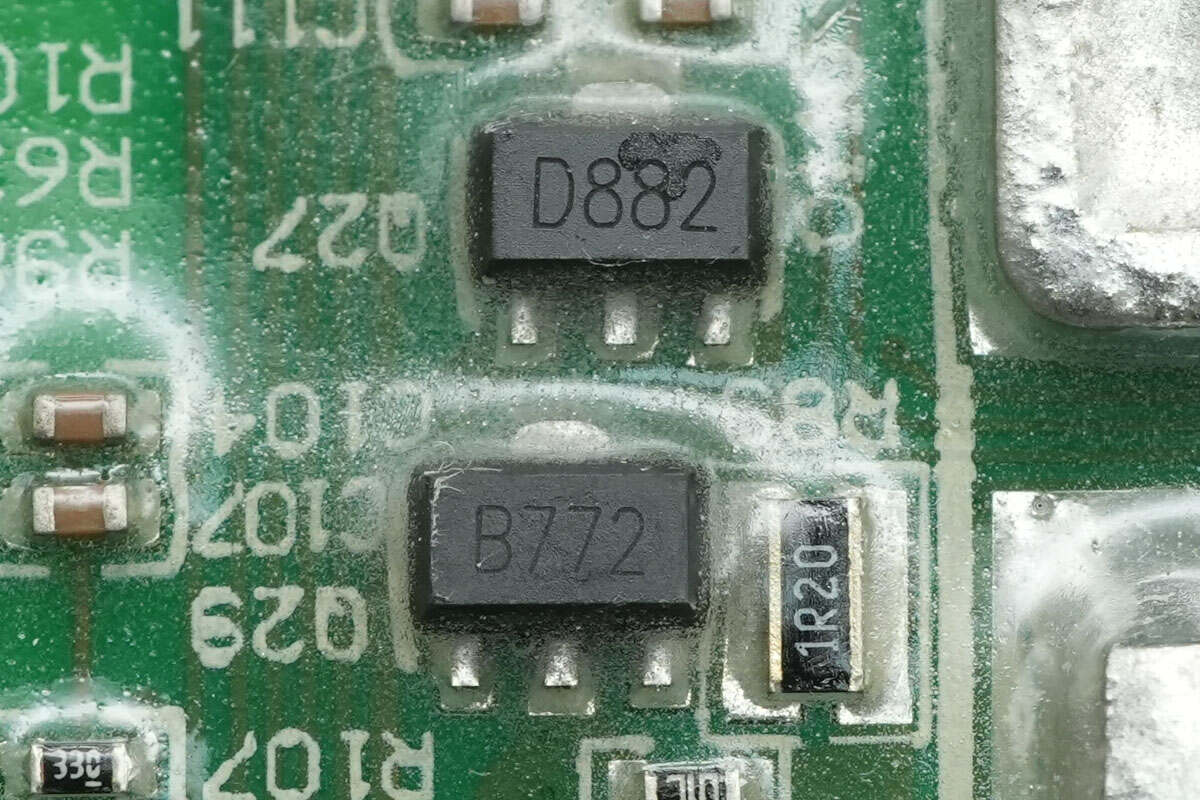
The other set of transistors has the same model numbers.
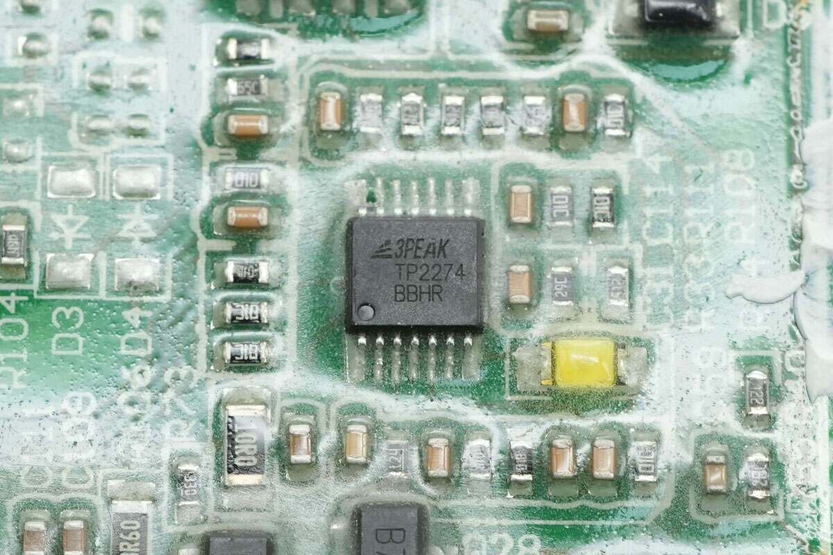
The 3PEAK TP2274 quad operational amplifier is used for constant voltage and constant current control in the power supply, housed in a TSSOP14 package.
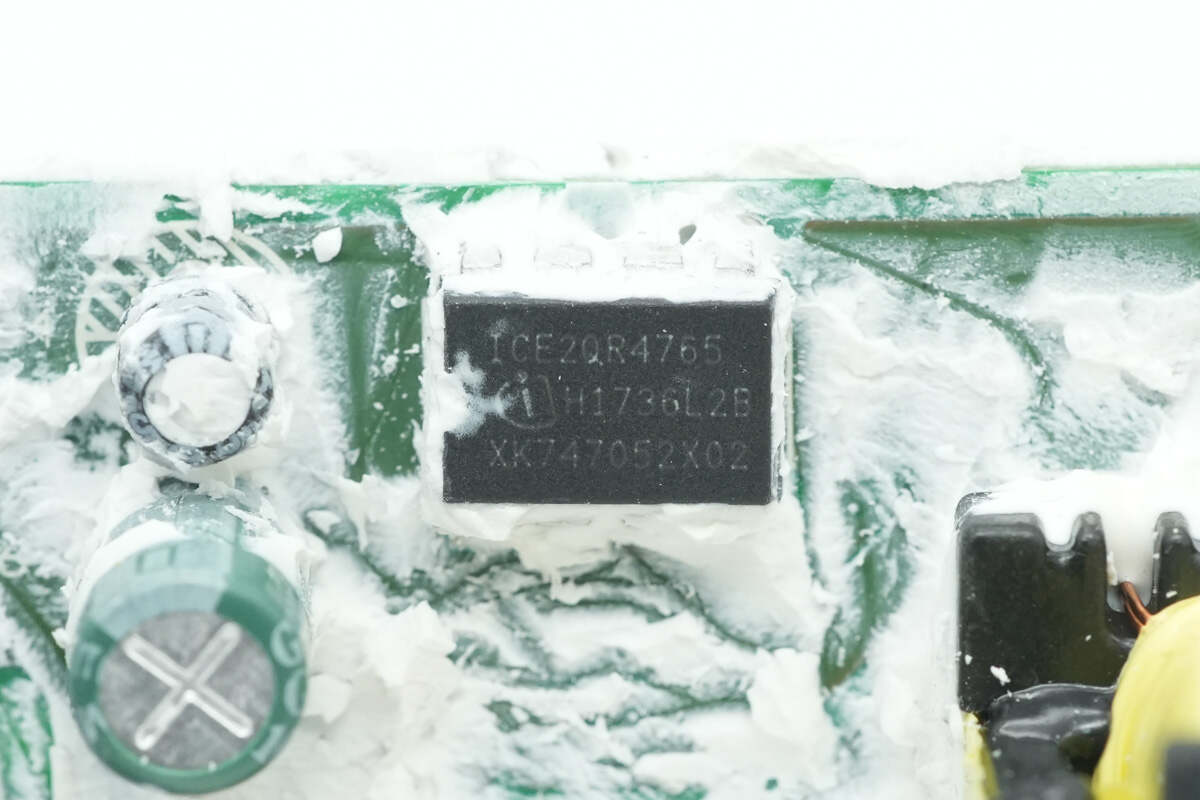
The standby power supply IC is from Infineon, model ICE2QR4765. It features a built-in 650V MOSFET, supports active burst mode to reduce standby power consumption, operates down to -40°C, delivers up to 19W output power over a wide voltage range, and comes in a DIP-8 package.
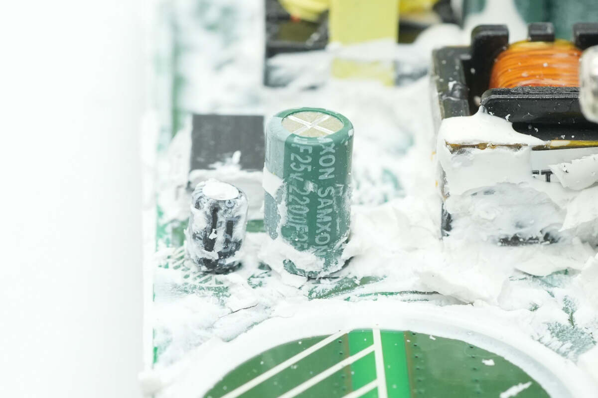
The filter capacitor that supplies power to the power chip has a specification of 220μF 25V.
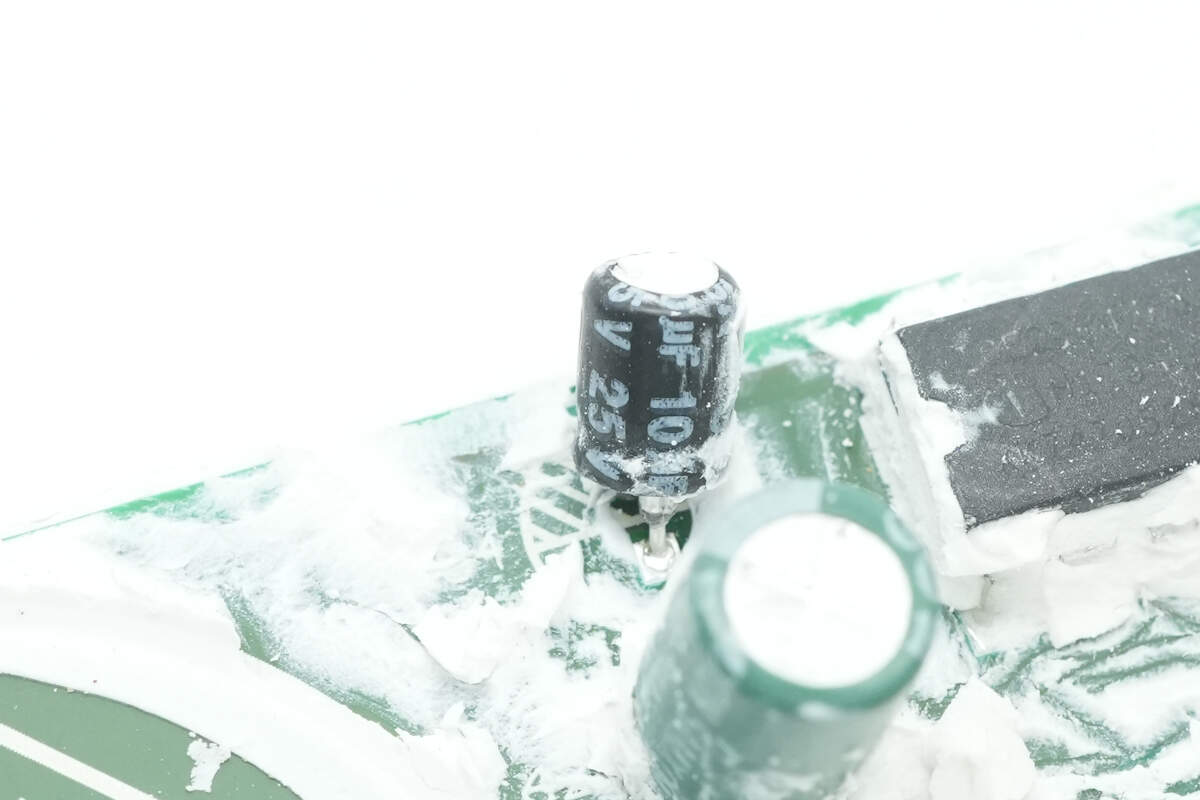
The other specification is 10μF 25V.
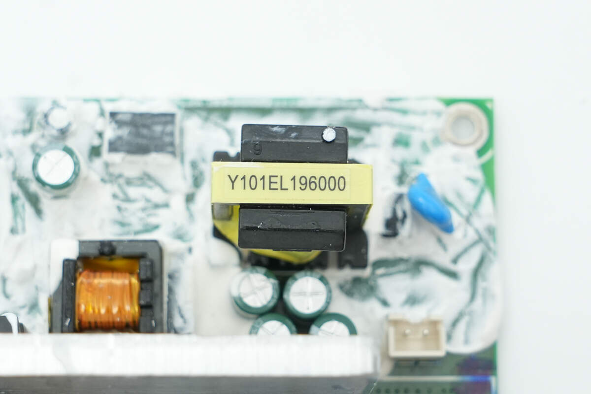
Close-up of the auxiliary power transformer.
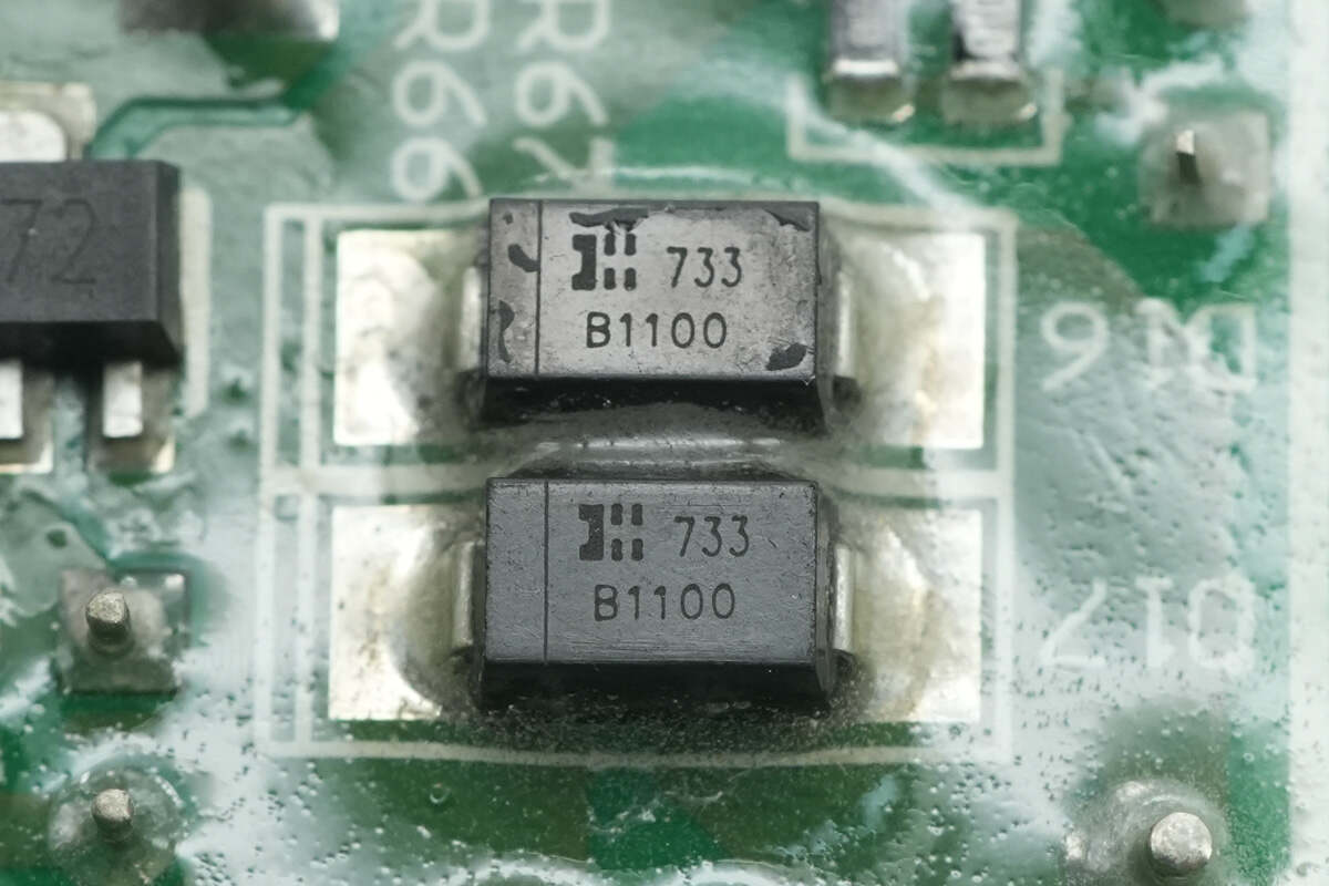
The rectifier diode is from DIODES, model B1100, specification is 1A 100V, and uses SMA package.
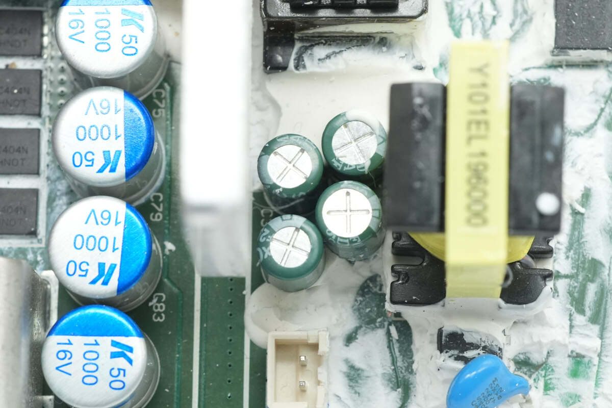
Close-up of the four filter capacitors at the output end.
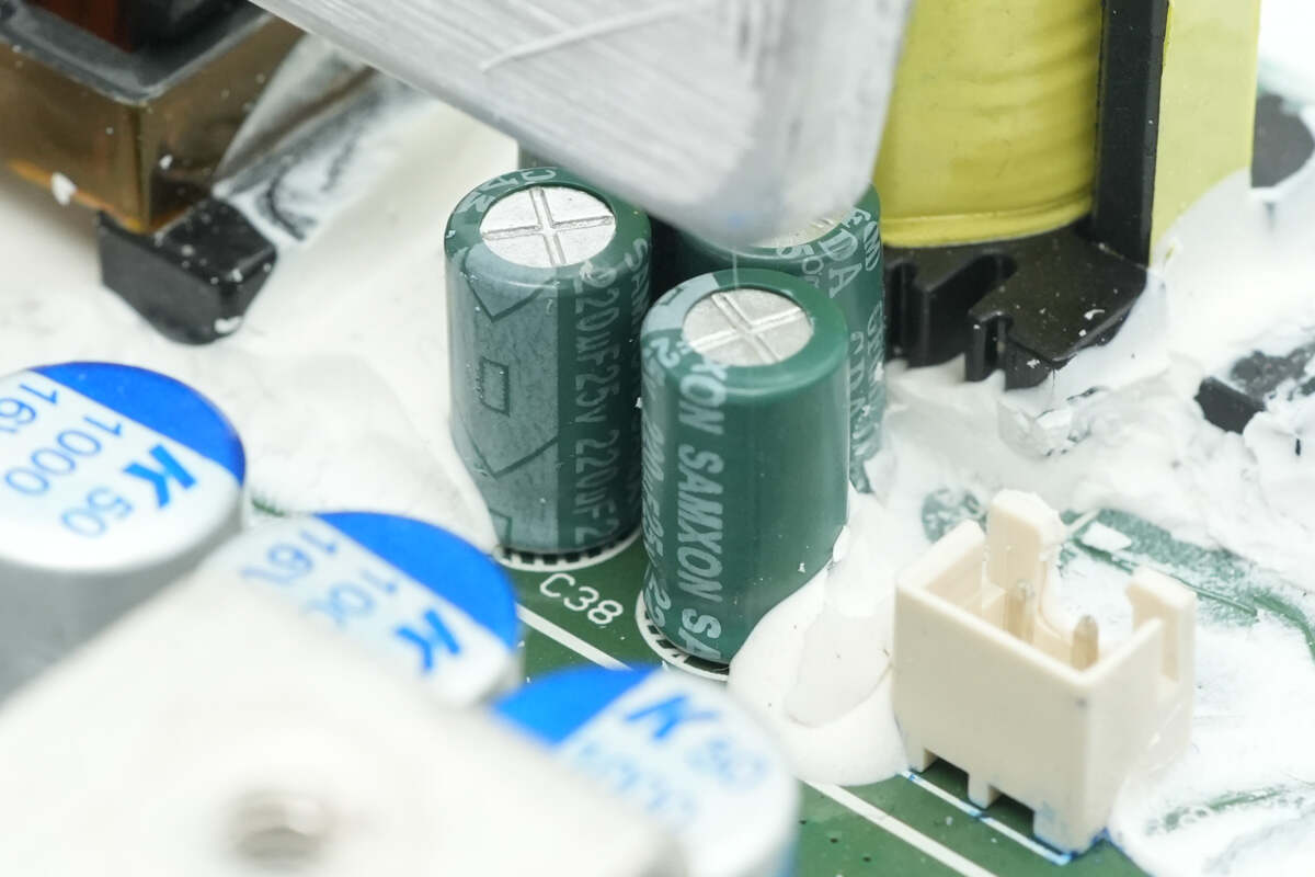
The capacitor specification is 220μF 25V.
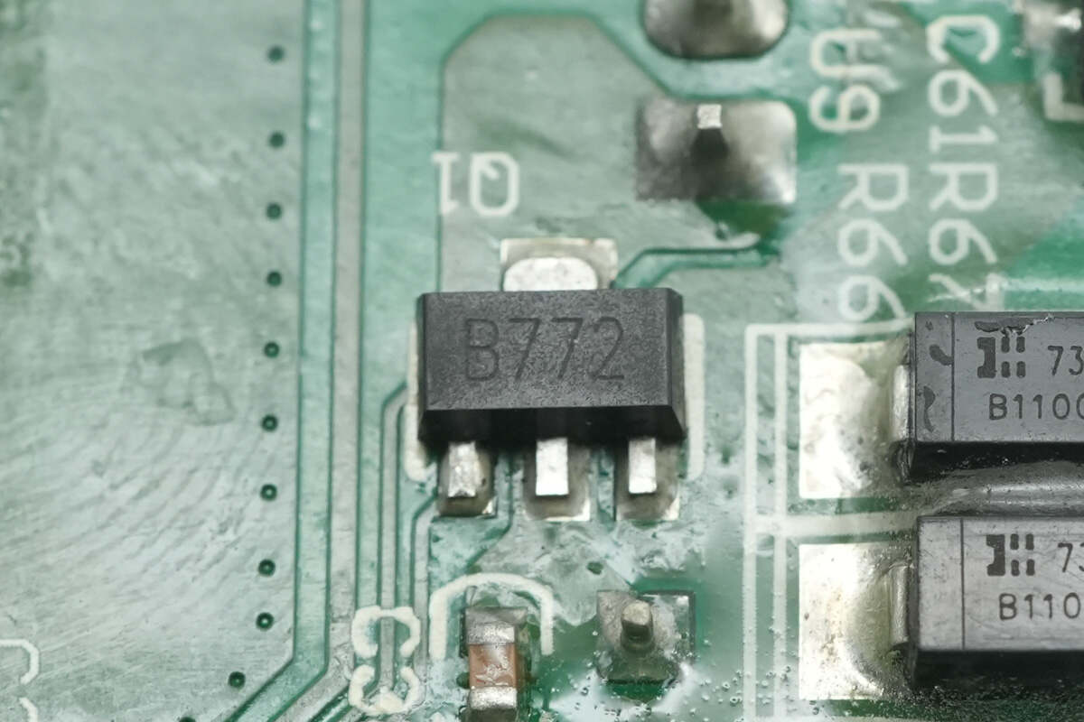
The B772 transistor is used to control the cooling fan.
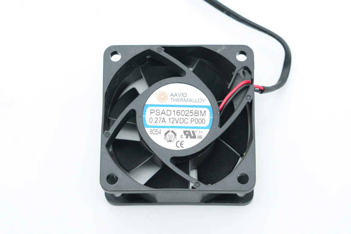
The cooling fan is from AAVID, model PSAD16025BM, rated at 0.27A 12V DC.

Well, those are all components of the Bitmain 1600W Power Supply.
Summary of ChargerLAB
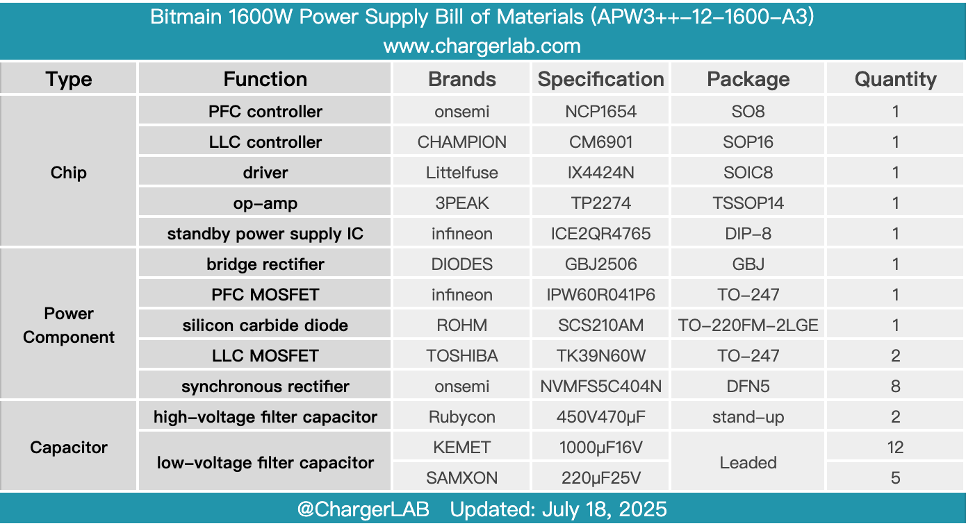
Here is the component list of the Bitmain 1600W Power Supply for your convenience.
It supports an input voltage of 200–240V and features a C14 power inlet. The power supply outputs 12V at 133A, delivering a total power of 1600W. The output side uses terminal posts connected to output cables. The cooling fan draws air in from the AC input side and exhausts it out from the output side for efficient heat dissipation.
After teardown, we found it employs a PFC + LLC architecture. The PFC controller is an Onsemi NCP1654 paired with an Infineon IPW60R41P6 MOSFET and ROHM SCS210AM silicon carbide diode. The LLC controller is a CHAMPION CM6901, which, together with a Littelfuse IX4424N driver and an isolation transformer, drives the LLC MOSFETs.
The LLC MOSFETs are from Toshiba, model TK39N60W. The synchronous rectifiers use Onsemi NVMFS5C404N devices. The high-voltage filter capacitors come from Rubycon, with a total capacitance of 940μF. Solid capacitors are from KEMET, with a combined capacitance of 12,000μF. Power components are reinforced with adhesive potting, and the PCBA module is coated with conformal coating for insulation and protection. Overall, the build quality and component selection are solid and reliable.
Related Articles:
1. Teardown of Newsmy P72 100W 72000mAh Portable Power Station
2. Teardown of HONOR 100W USB-C GaN Charger
3. Teardown of AOHi The Youth PD 65W GaN 3-Port Charger (AOC-C019)