Introduction
The 1600W silicon carbide server power supply YSEF1600EM from 3Y POWER has achieved 80 PLUS Platinum certification. It supports 100–240V AC input and 190–310V DC input, with an output voltage of 12.2V and an output current of 130A. The standby power output is 12V with a current of 2A.
The input side features a cooling fan, a power socket, and indicator lights. The output side includes a gold-finger connector. The power supply adopts a PFC + full-bridge LLC + synchronous rectification architecture, using STMicro and Onsemi controllers. Below, we take a closer look at the internal design and components.
Product Appearance

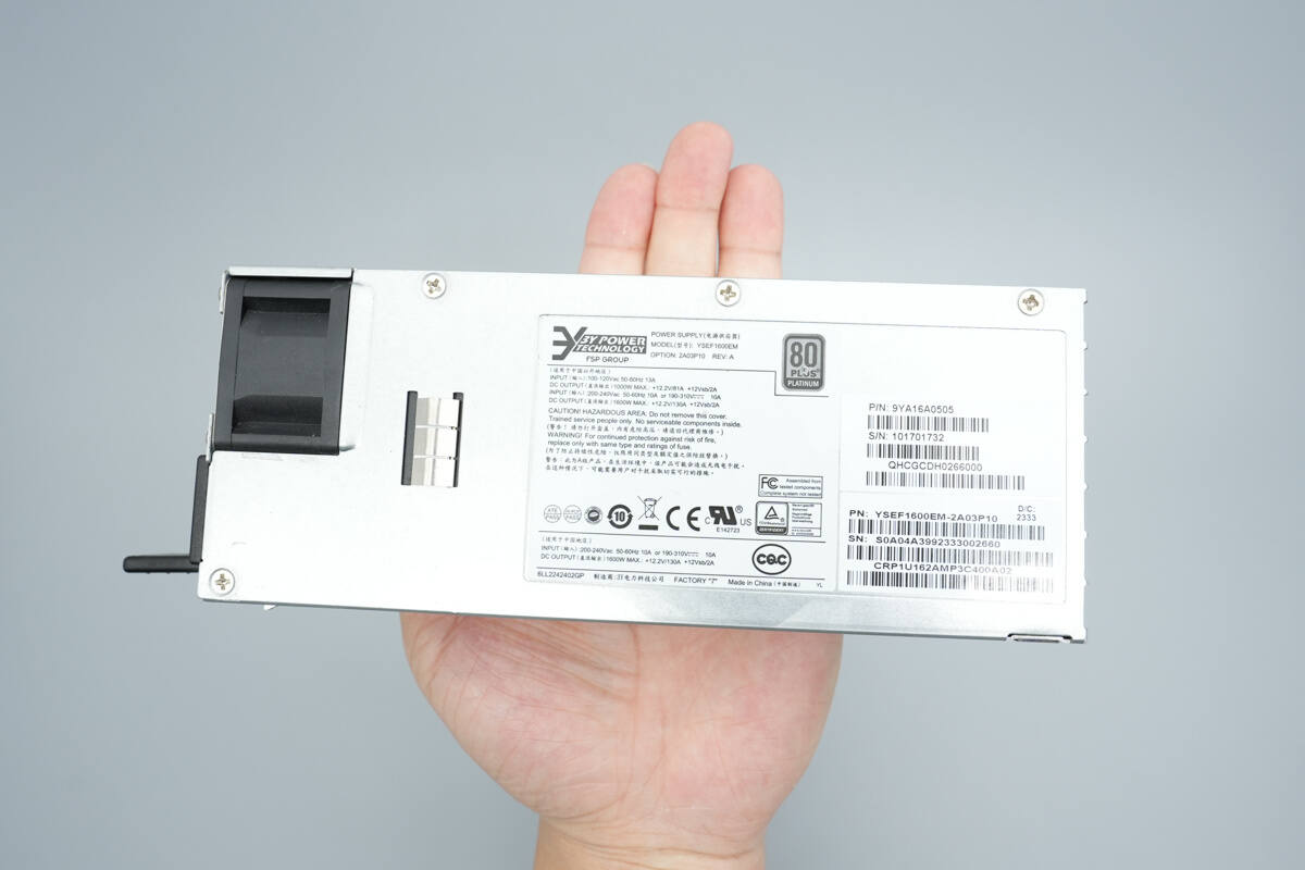
It uses a metal casing with an information label attached.

Model: YSEF1600EM
Input: 100–120V AC, 50–60Hz, 13A
DC Output: 1000W MAX: +12.2V / 81A, +12Vsb / 2A
Input: 200–240V AC, 50–60Hz, 10A or 190–310V DC, 10A
DC Output: 1600W MAX: +12.2V / 130A, +12Vsb / 2A
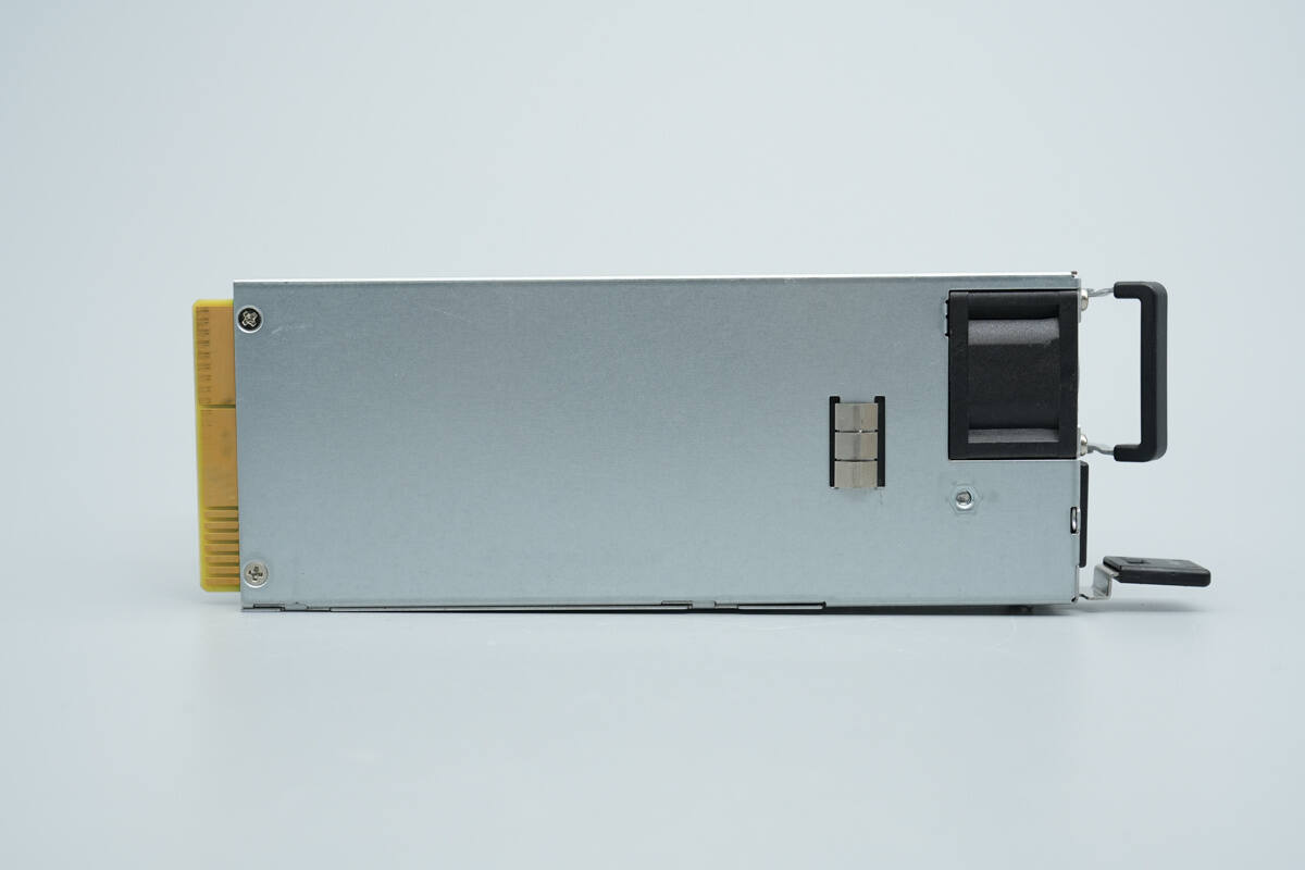
A grounding clip is installed on the back.
There is a locking latch on the side.
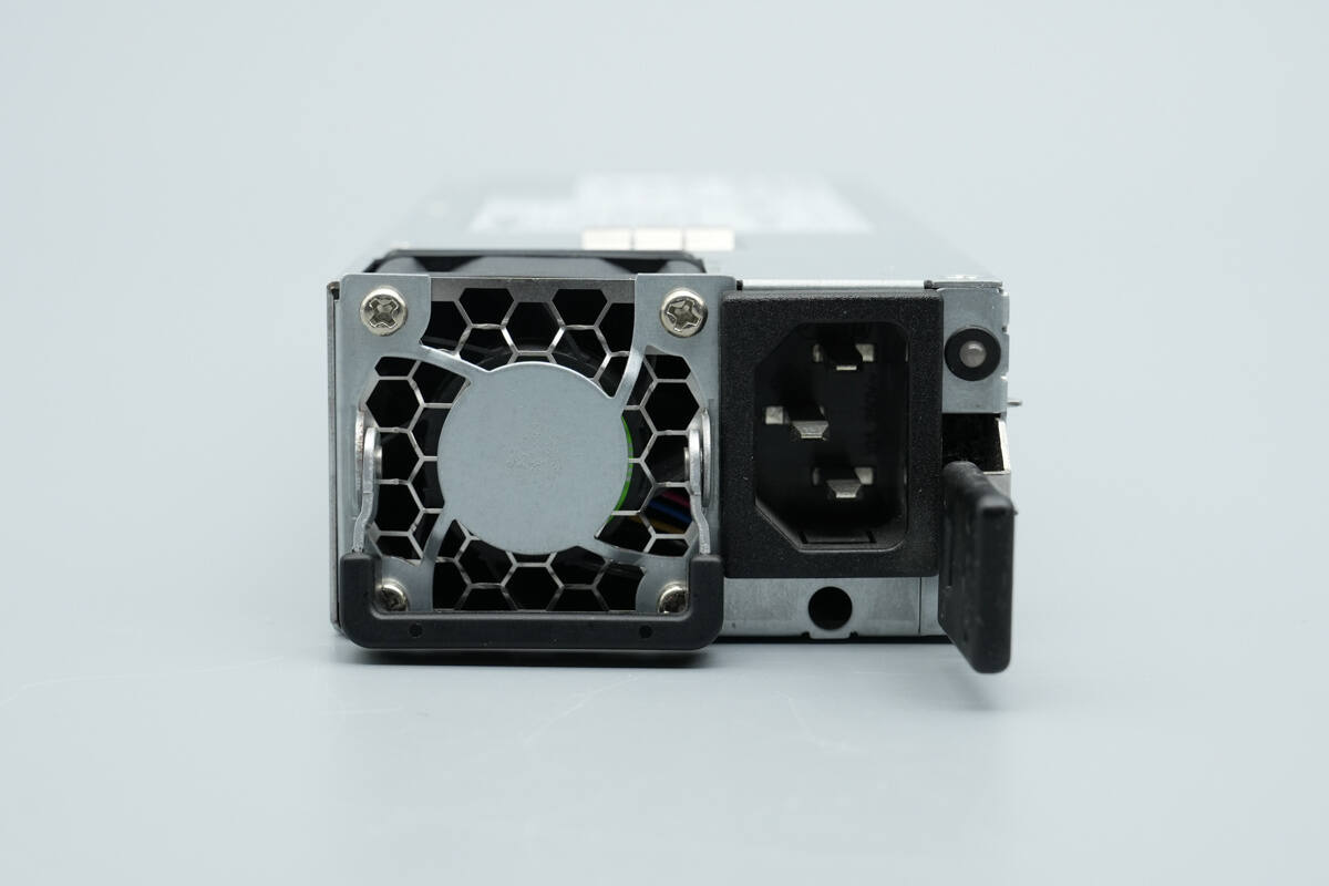
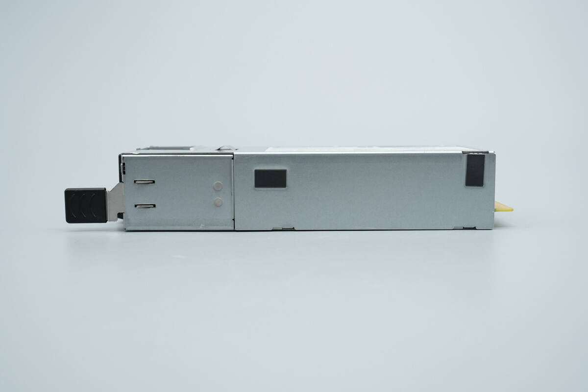
The input side is equipped with a cooling fan, input socket, locking handle, and power indicator light.
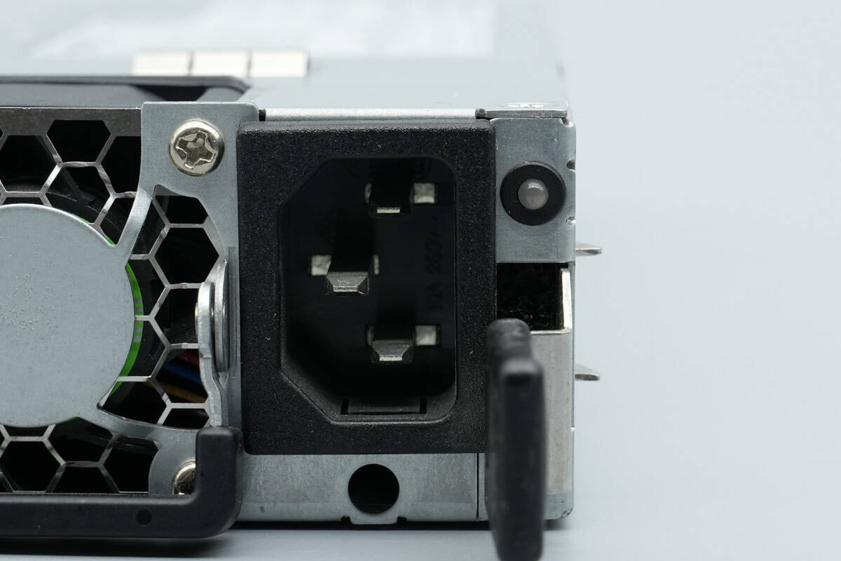
Close-up of the input socket and power indicator light.
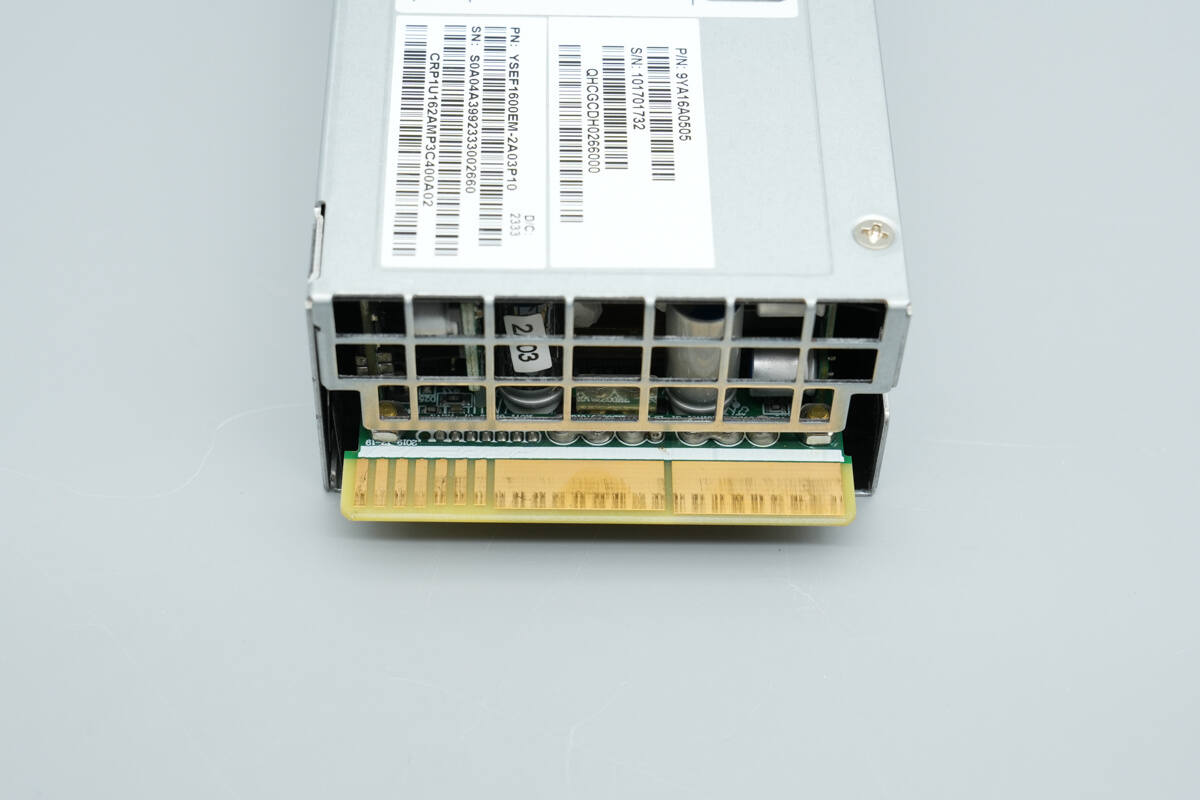
The output side is equipped with a protective grille and gold-finger connector.
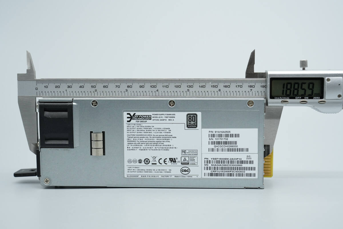
The length of the module is about 188.6 mm (7.43 inches).

The width is about 73.5 mm (2.89 inches).
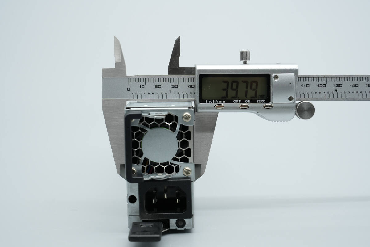
The thickness is about 39.8 mm (1.57 inches).
That's how big it is in the hand.
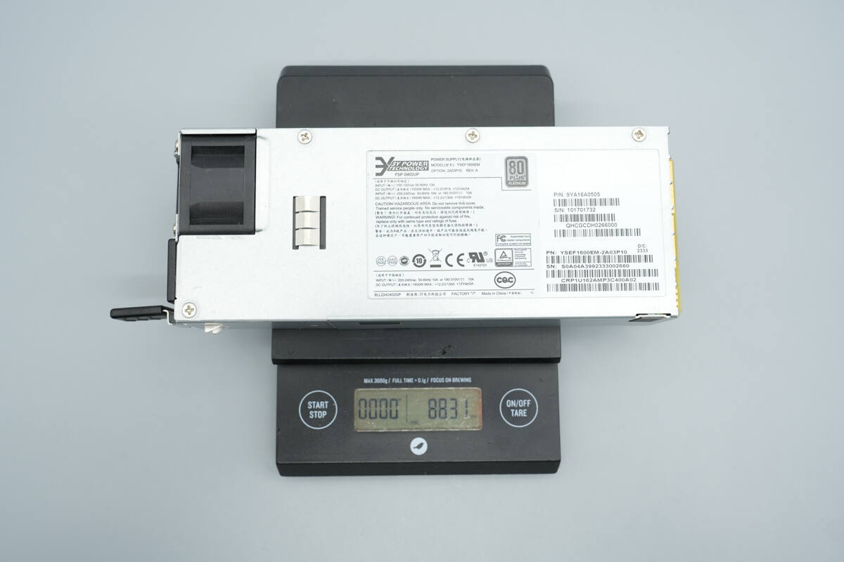
The weight is about 883 g (31.15 oz).
Teardown
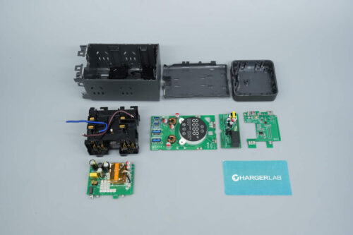
Next, let's take it apart to see its internal components and structure.
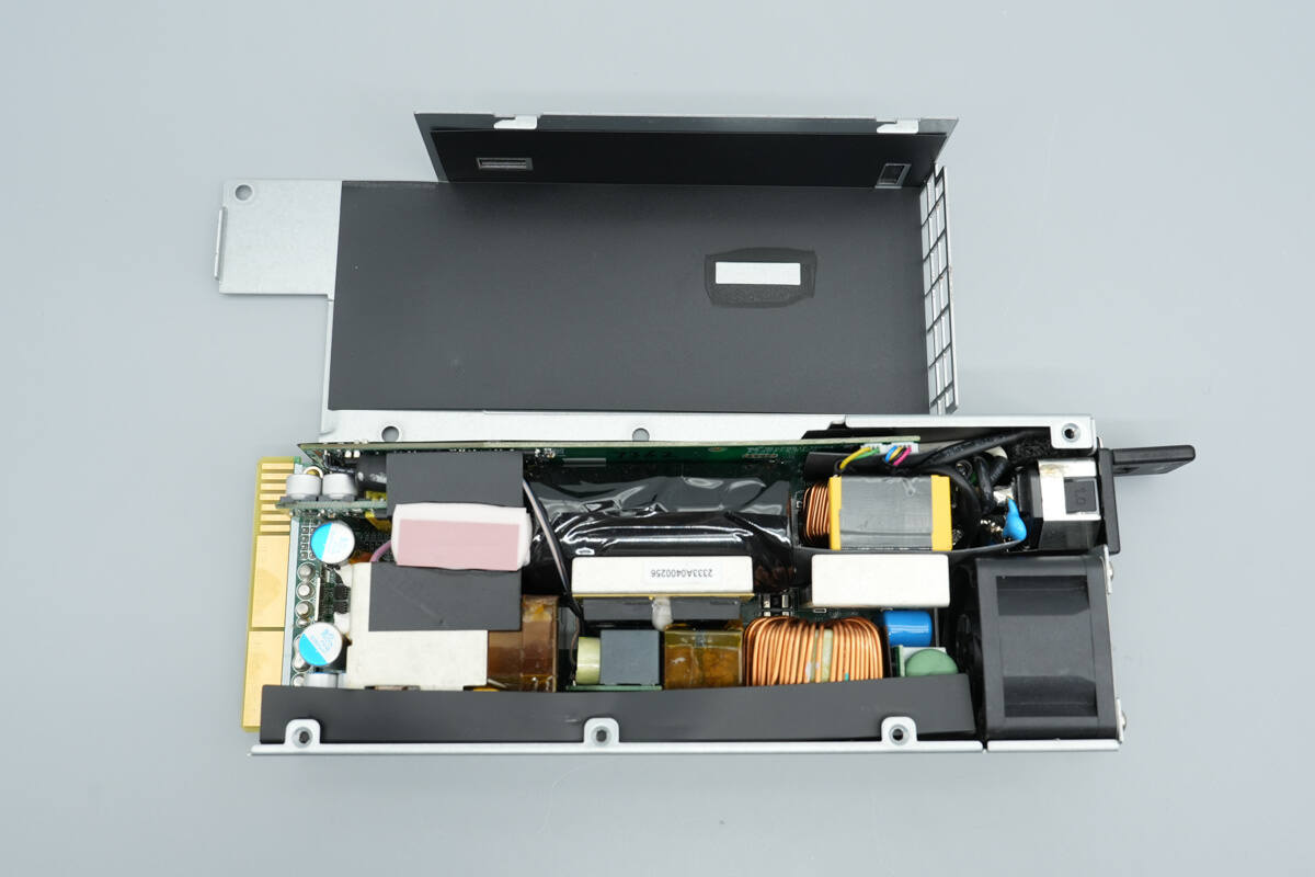
First, unscrew the screws and remove the casing. The inside of the top cover is insulated with a Mylar sheet.
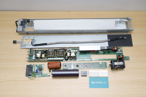
The PCBA module is secured inside the casing with screws.
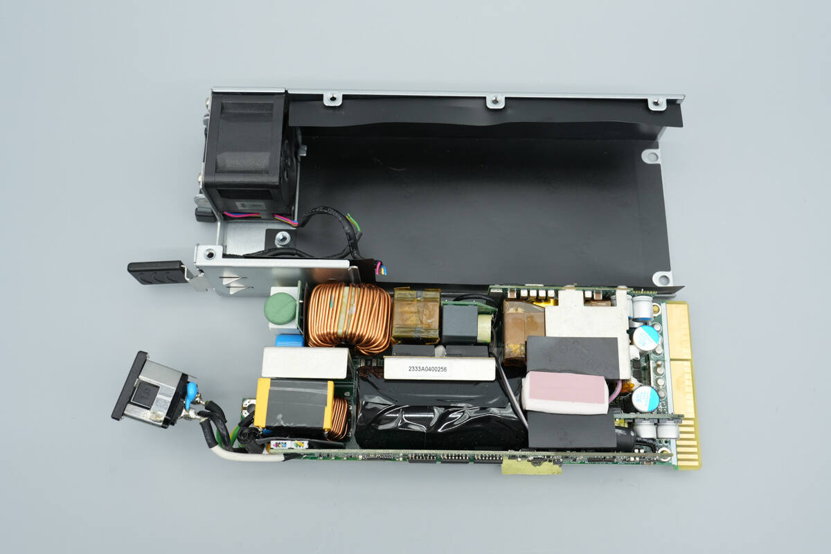
After removing the PCBA module, a Mylar sheet is present inside the casing.

The input wires are connected by soldering.

The wires are soldered to crimp terminals and insulated with heat-shrink tubing.
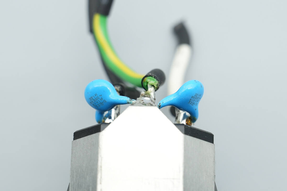
The blue Y-capacitors on the socket are from MURATA, part number 221K.

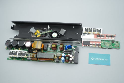
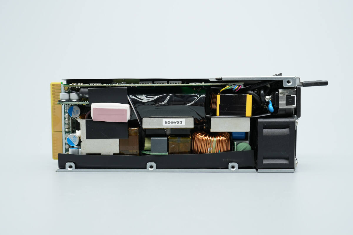
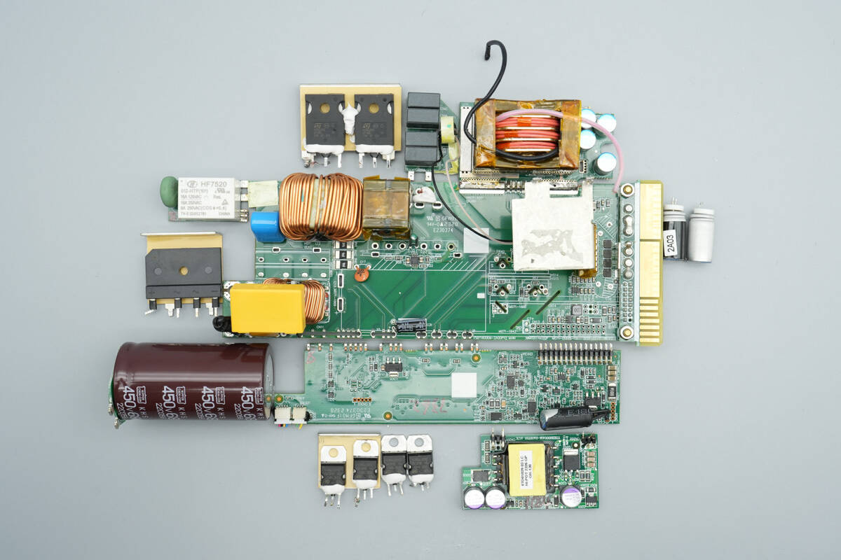
The front side of the PCBA module features components such as a fuse, Y-capacitors, a varistor, a common mode choke, a safety X2 capacitor, a bridge rectifier, a relay, a PTC resistor, a PFC boost inductor, a resonant inductor, and resonant capacitors.
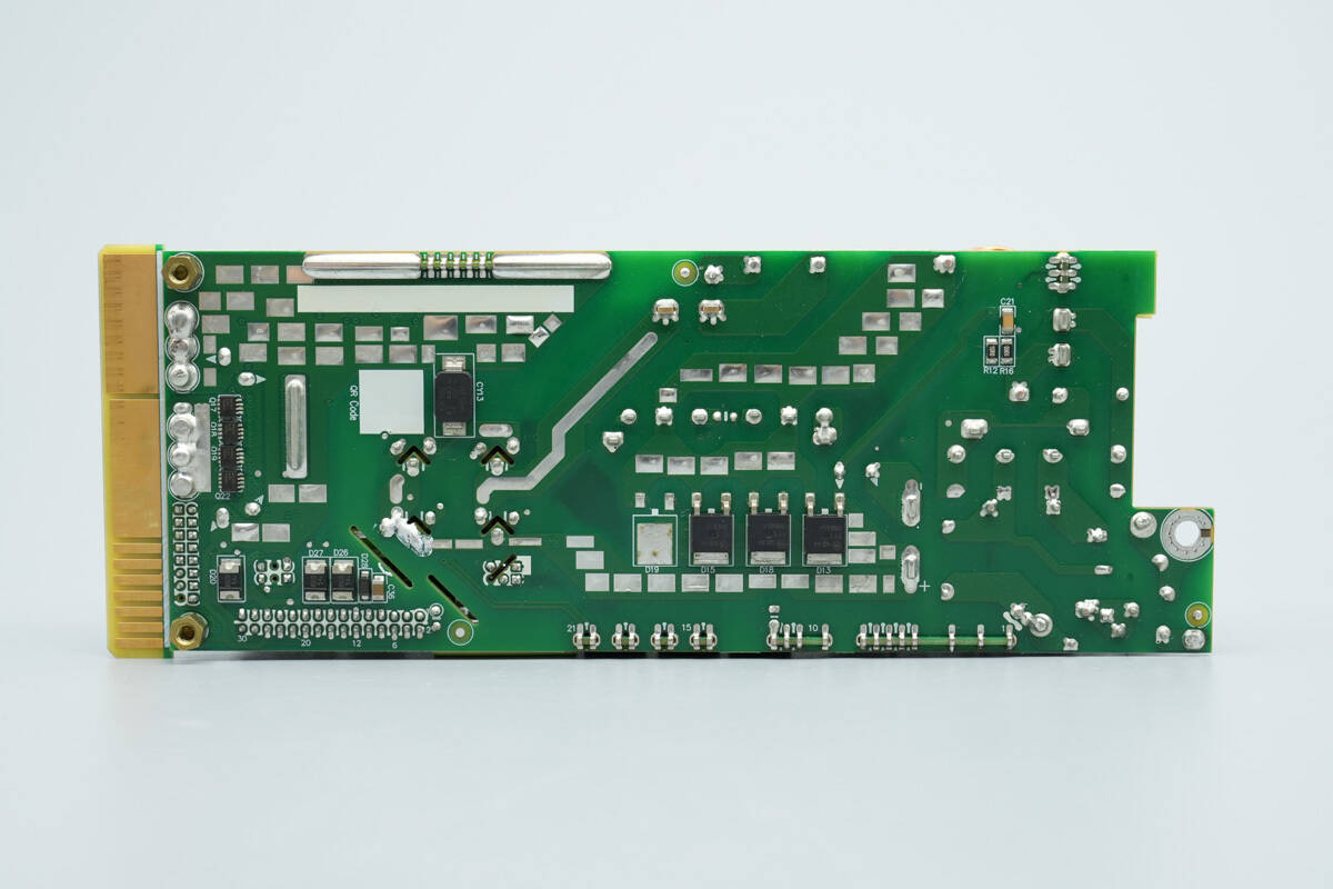
The back side features PFC rectifiers, an SMD Y-capacitor, and output control MOSFETs.
Remove some components to continue the disassembly.

This side is equipped with a varistor and a control PCB.
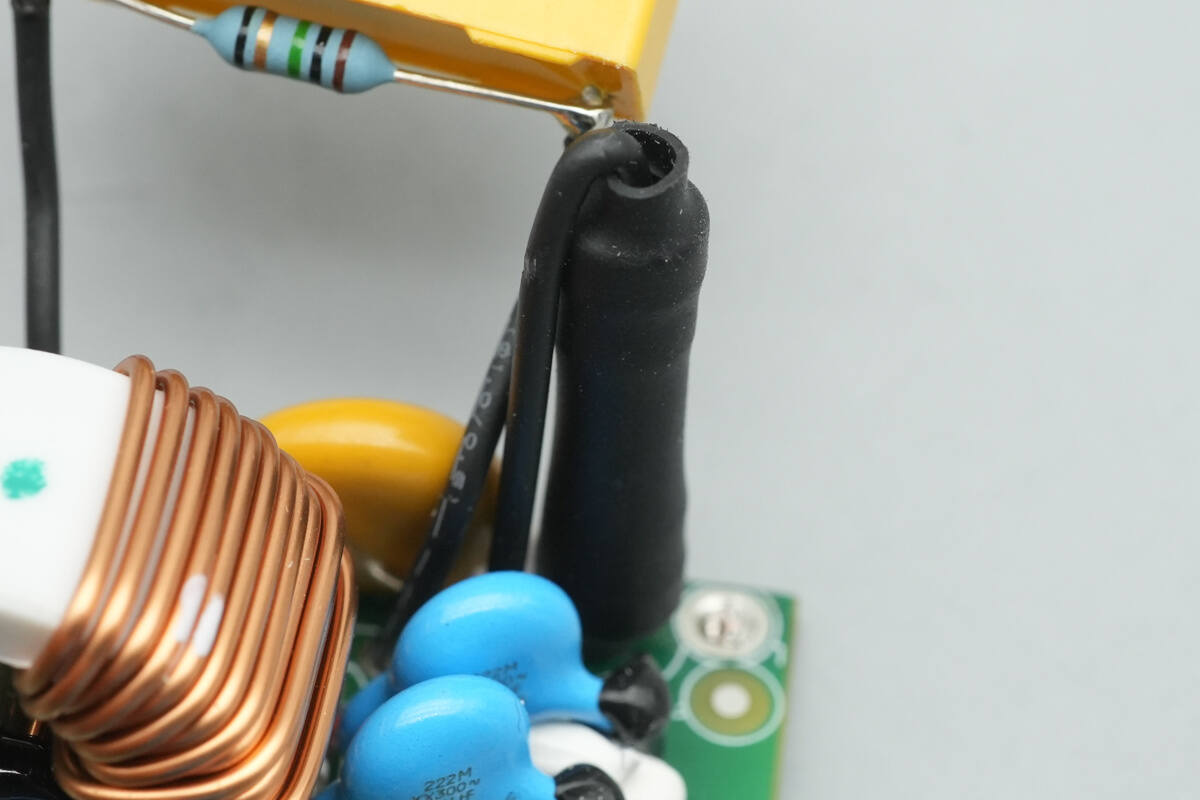
The input fuse is insulated with heat-shrink tubing.

The varistor, marked TVR10471, is used to absorb overvoltage surges.
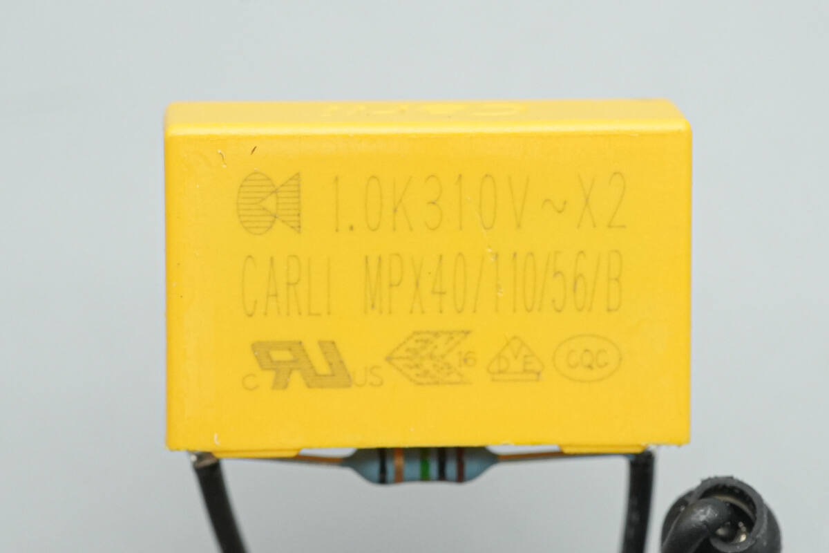
The safety X2 capacitor is from Carli, with a specification of 1 μF.

The blue Y-capacitors are from MURATA, part number 222M.
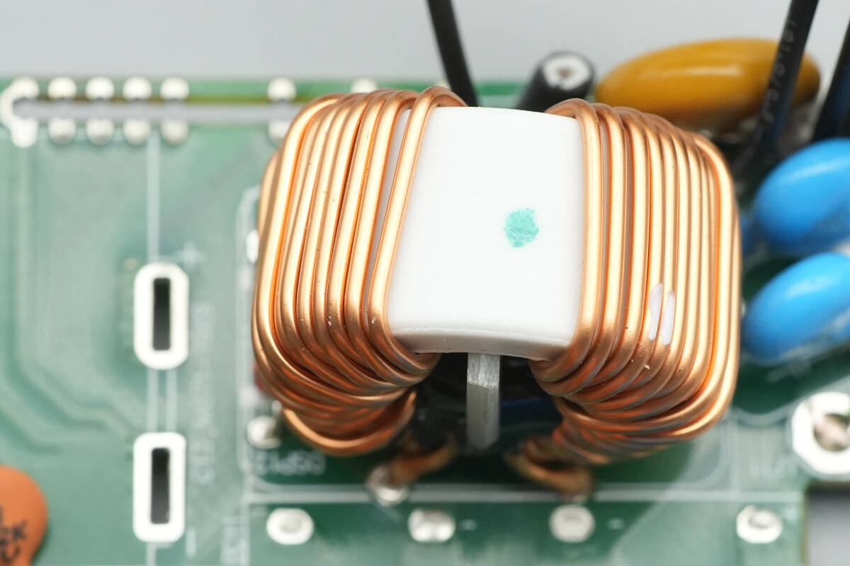
The common mode choke is wound with enameled wire.
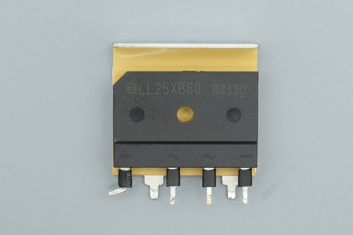
The bridge rectifier is from Shindengen, model LL25XB60, rated 25A 600V, and uses a 5S package.

The film capacitor is from Nitsuko, part of the FPS series, model FPS22W225K, rated 2.2 μF 450 V.
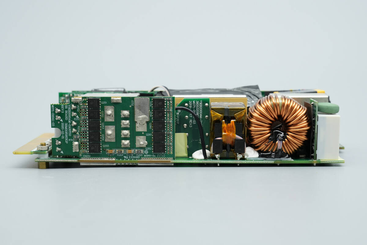
The other side is equipped with a relay, PFC boost inductor, LLC resonant capacitors, and a synchronous rectification PCB.
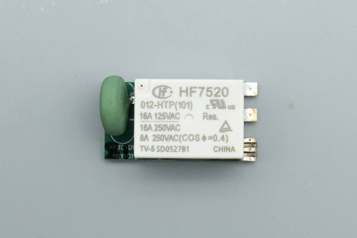
The PTC resistor and relay are soldered onto a separate PCB.
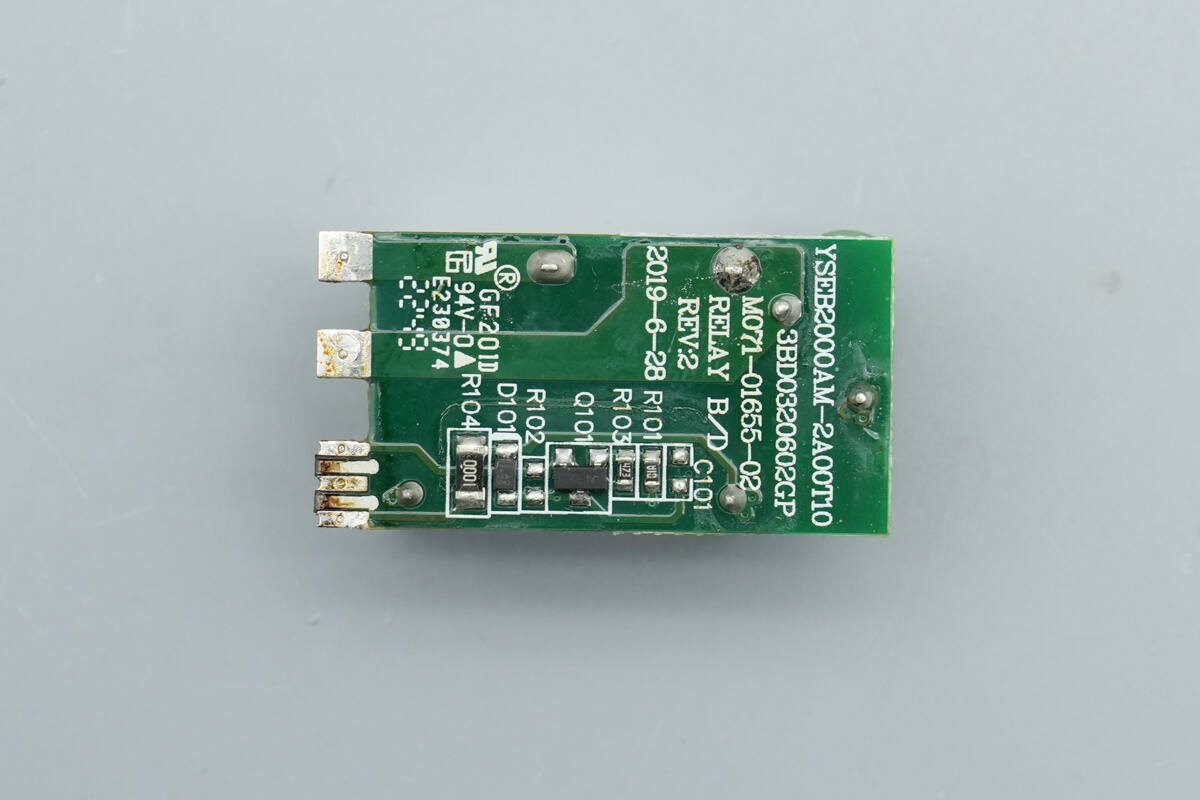
On the back side of the small PCB, there is a driver transistor.
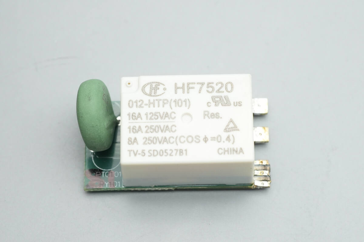
The relay is from HONGFA, model HF7520/012-HTP. It is an ultra-compact high-power relay with a single normally open contact. The contact is a high-load type, rated at 16A 250 VAC, and the coil voltage is 12 V.
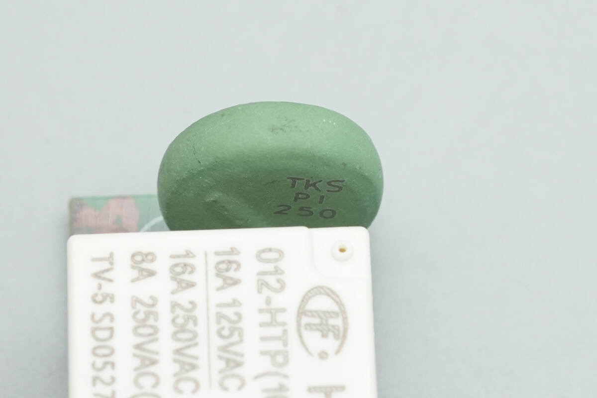
The PTC resistor is from Thinking, marked TKSPI250.
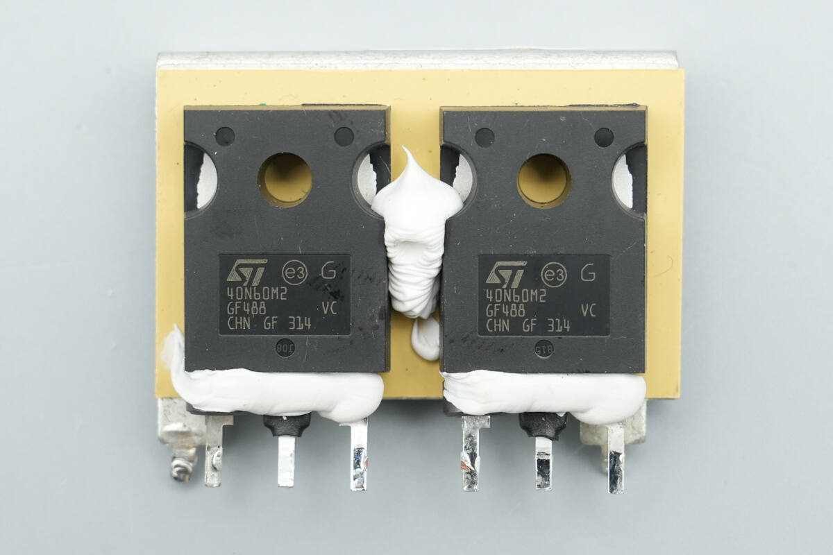
The PFC MOSFETs are from STMicro, model STW40N60M2. They are NMOS devices with a voltage rating of 650 V and an on-resistance of 78 mΩ, housed in a TO-247 package.

The PFC MOSFET driver is from Onsemi, marked 071B, model NCP81071B. It is a high-speed dual low-side driver, supporting a 4.5–20 V operating voltage and 5 A output current, housed in an MSOP8EP package.

A thermistor is placed between the two PFC MOSFETs to monitor temperature.

The PFC boost inductor is wound with enameled wire.
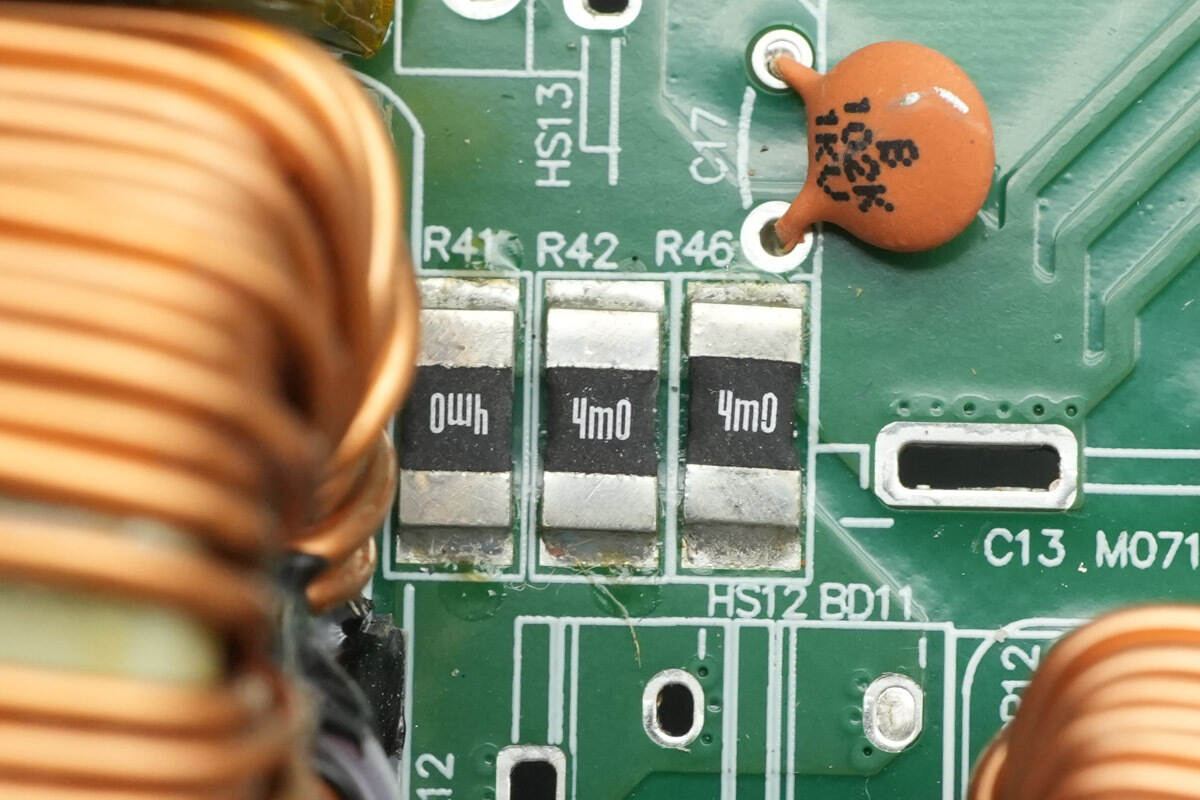
Three 4 mΩ sense resistors are used to monitor the current of the PFC MOSFETs.

The PFC rectifiers are from Onsemi, model FFSD0665A. They are silicon carbide Schottky diodes, rated 650 V 6 A, and come in a DPAK package.
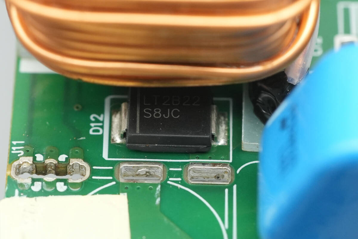
The bypass diode is from LITEON, model S8JC, rated at 600V and 8A, and comes in an SMC package.
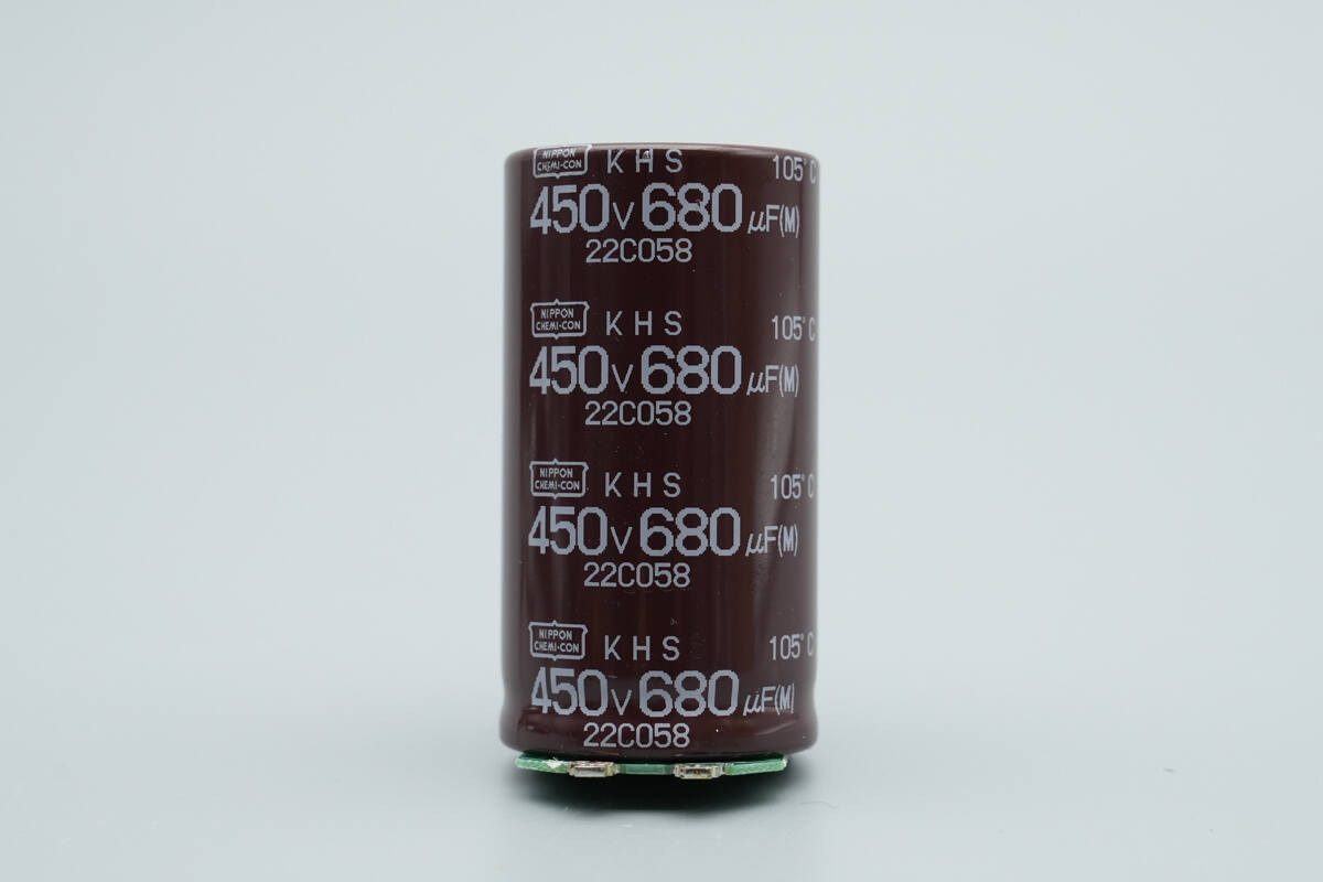
The high-voltage filter capacitor is from NCC, a KHS series self-supporting electrolytic capacitor, rated for 105 °C, with specifications of 450 V and 680 μF.
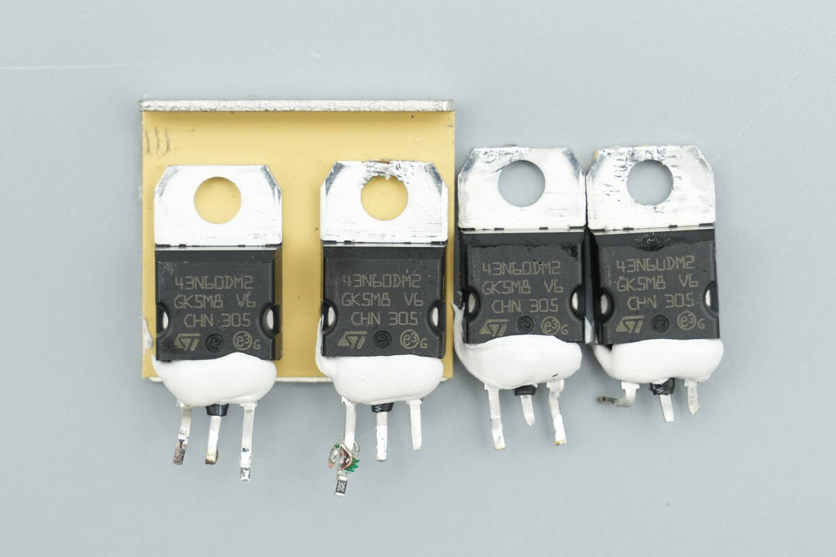
The LLC MOSFETs are from STMicro, model STP43N60DM2, NMOS type, rated at 650 V with an on-resistance of 85 mΩ, and packaged in TO-220.
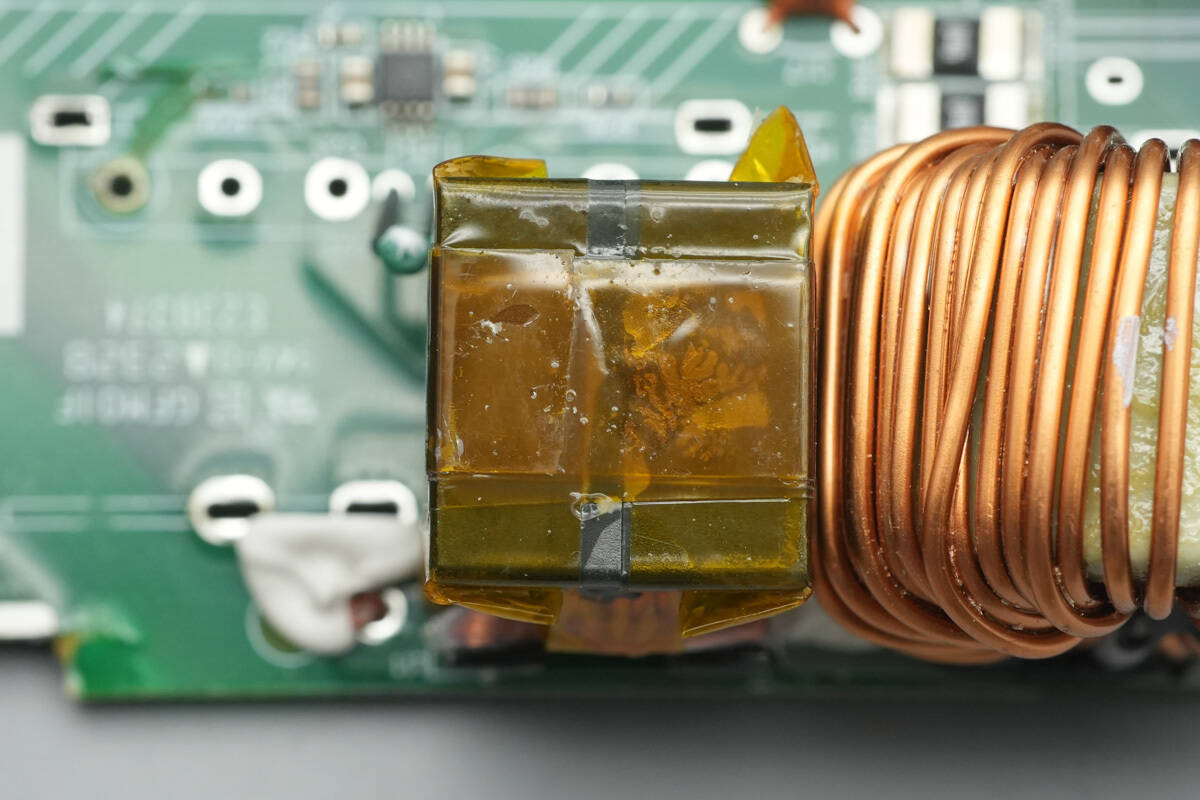
The resonant inductor is tightly wound and insulated with high-temperature tape.
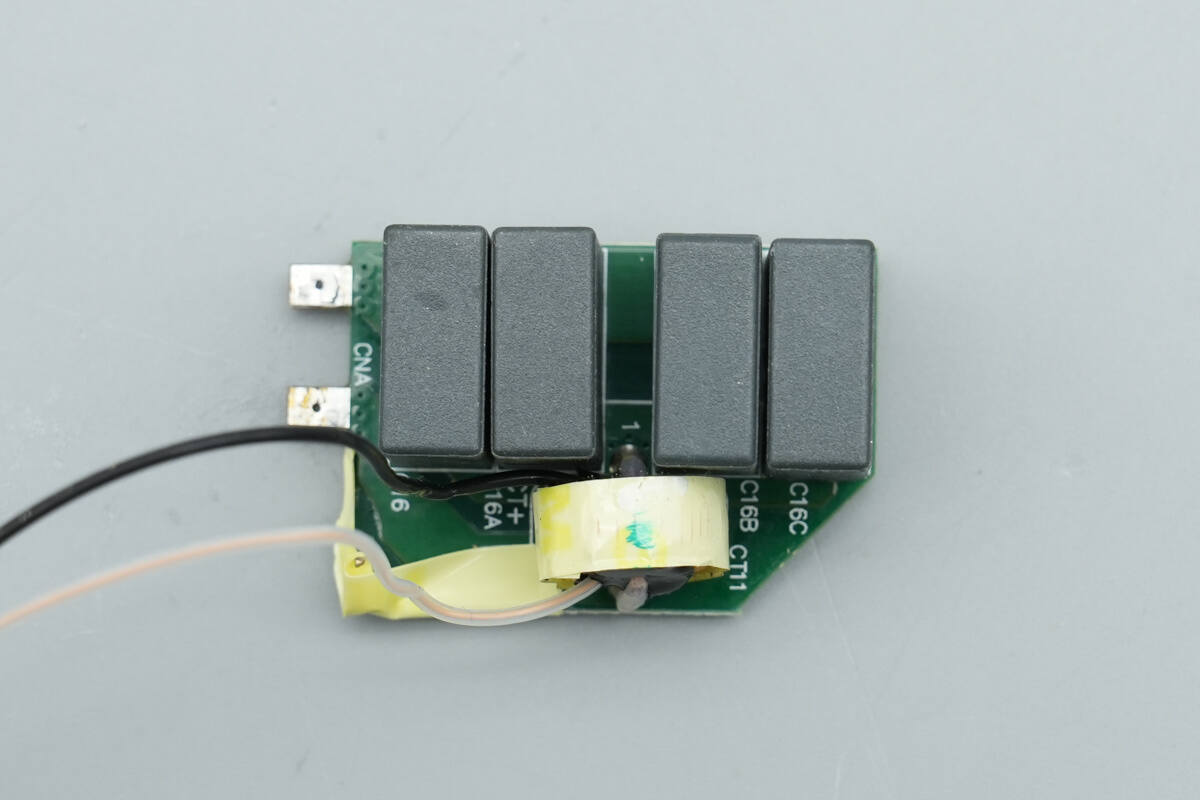
The resonant capacitors and current transformer are soldered onto a dedicated PCB.
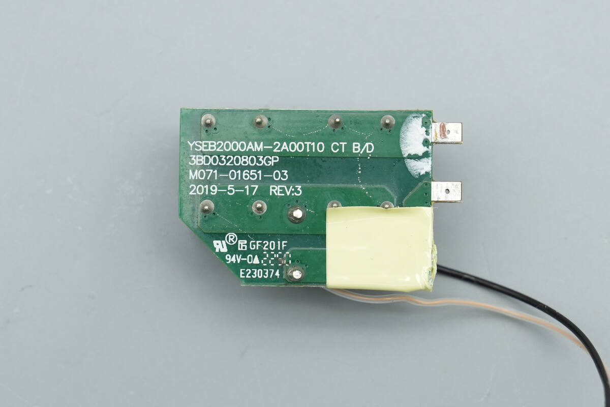
There are no components on the backside.
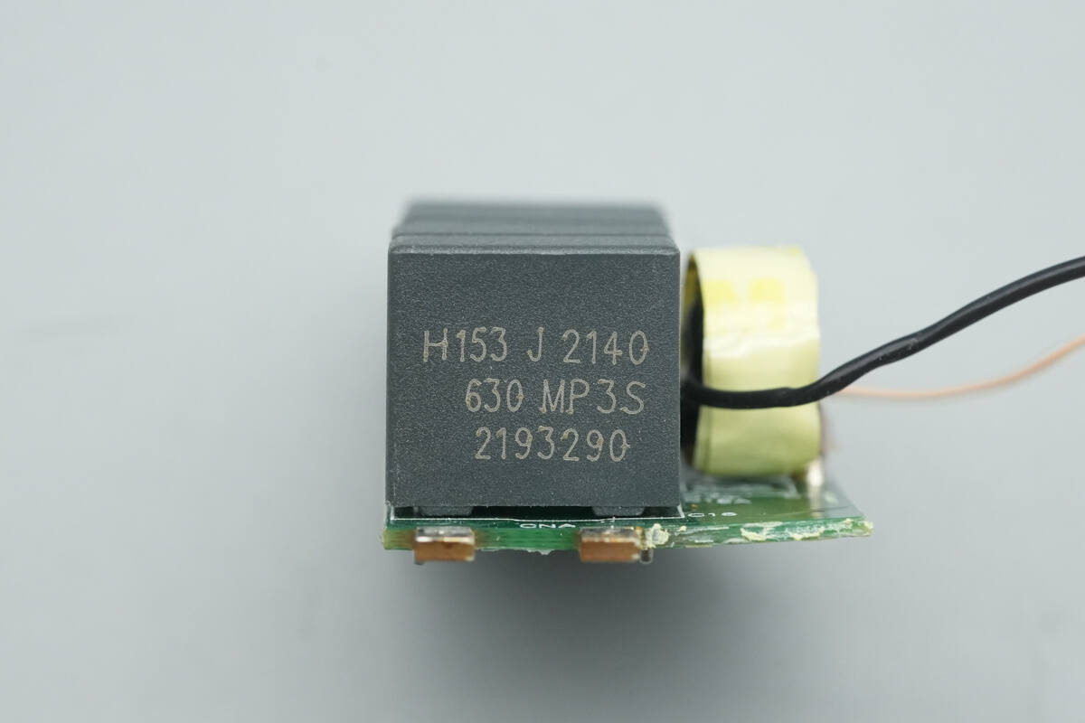
The resonant capacitors are rated at 0.015 μF, 630 V, with four units connected in parallel.

The current transformer is constructed using a toroidal winding.
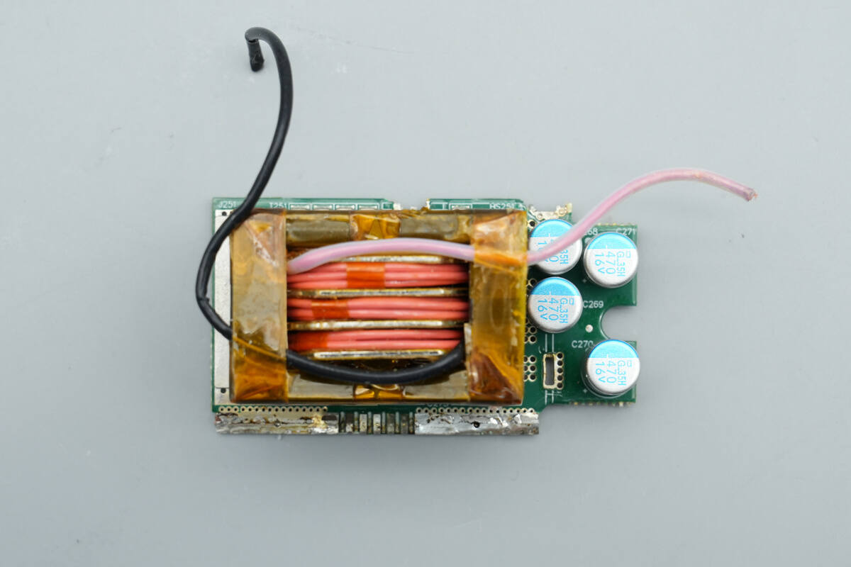
The transformer is soldered onto a vertically mounted PCB, with filter capacitors positioned to the right of the transformer.

There are two sets of synchronous rectifiers on the backside.

The transformer primary is wound with Litz wire, while the secondary is constructed using soldered copper strips. The magnetic core is tightly wrapped with tape for insulation.
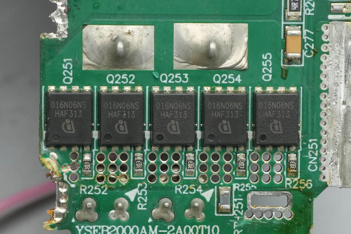
The synchronous rectifiers are from Infineon, model BSC016N06NS, NMOS type, rated at 60 V with an on-resistance of 1.1 mΩ, and packaged in TDSON-8. A thermistor is placed underneath for temperature monitoring.
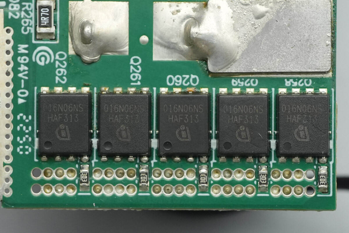
The other set of synchronous rectifiers is of the same model.

The filter capacitors are from NCC, part of the PSG series of compact, long-life solid-state capacitors, rated at 470 μF and 16 V.

The driver is an Onsemi NCP81071B.
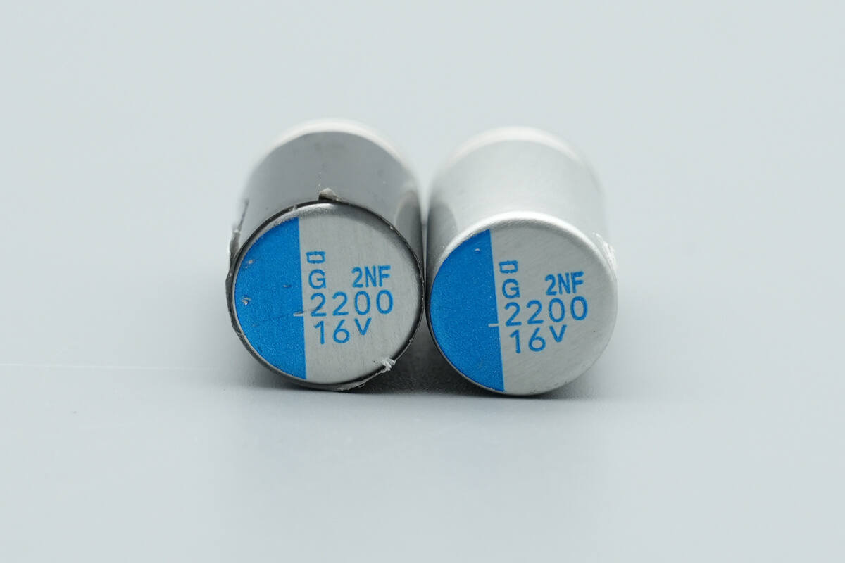
The output filter capacitors are rated at 2200 μF and 16 V.

Inductors for filtering are formed by magnetic cores mounted on the connecting copper strips.
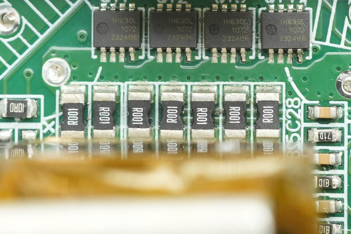
Seven 1 mΩ resistors are connected in parallel for output current sensing.

The Op-Amp is from TI, marked OSUI, model OPA171. It is a 36 V single-supply general-purpose Op-Amp, packaged in SOT-23.
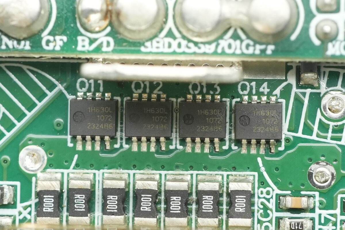
The output control MOSFETs are from Nexperia, marked 1H630L, model PSMN1R6-30MLH, NMOS type, rated at 30 V with an on-resistance of 1.6 mΩ, and packaged in LFPAK33.

On the backside, there are four output control MOSFETs of the same model.
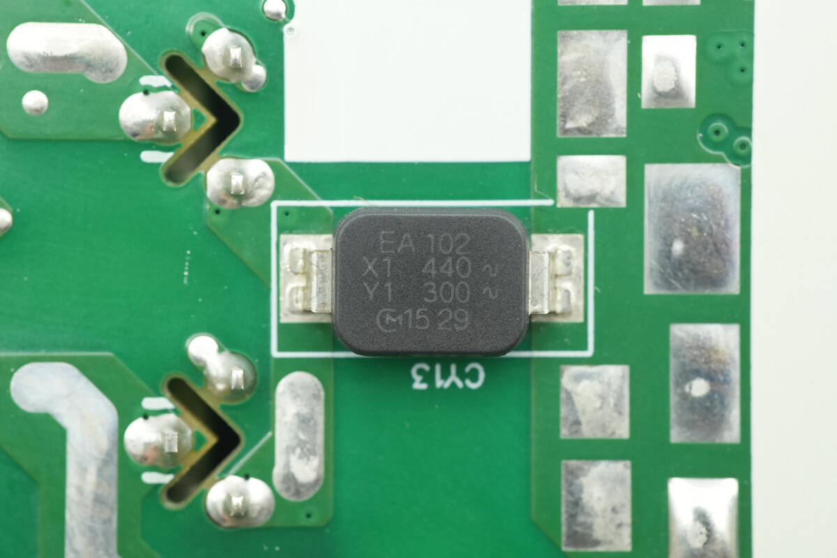
The SMD Y capacitor is from MURATA, part of the DK1 series, with the part number EA102.

The filter capacitor is from Rubycon, rated at 25 V and 68 μF.
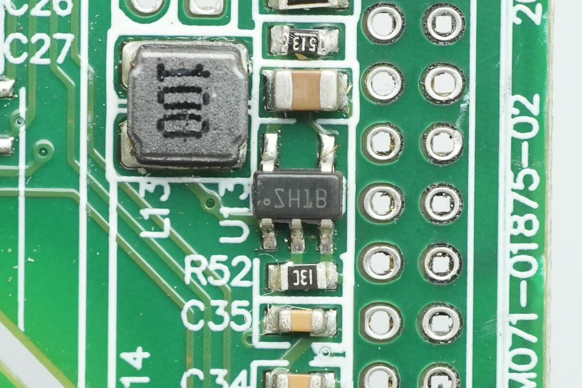
The boost chip is from TI, marked SH1B, model LMR62014. It supports an input voltage of 2.7–14 V and can output up to 20 V. It features an internal MOSFET, supports a switching current of 1.4 A, operates at a switching frequency of 1.6 MHz, and is packaged in SOT-23.

Close-up of the 10 μH boost inductor.

The Schottky diodes are from ZOWIE, model BSCD54H, rated at 40 V and 5 A, and packaged in DO-214AA.

The other Schottky diode is of the same model.

The outer side of the control PCB features a PFC controller, digital isolator, additional digital isolators, an LLC controller, an MCU, a digital isolator, and an electronic fuse.

The other side contains regulators, memory, a voltage comparator, and Op-Amps, among other components.

The PFC controller is from STMicro, model STM32F334K8T6. It is a mixed-signal MCU with an integrated DSP and FPU, featuring an ARM Cortex-M4 CPU with a 72 MHz clock. It includes 64 KB of Flash memory, 12 KB of SRAM, as well as built-in ADC, DAC, comparators, and Op-Amps. The device is packaged in LQFP32.
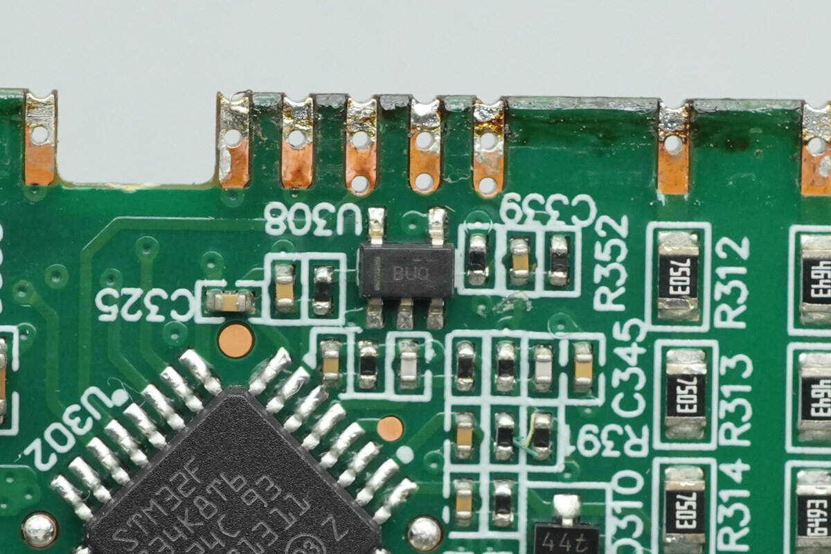
The Op-Amp is from TI, marked BUQ, model OPA376. It is a precision, low-quiescent-current Op-Amp with rail-to-rail input and output, packaged in SOT-23.

The regulator is from Microchip, model MIC52093.3YS. It supports an input voltage up to 20 V, provides a 3.3 V output, delivers up to 500 mA of current, and is packaged in SOT-223.

The LLC controller is from Onsemi, model NCP4390. It features synchronous rectification, operates with current-mode control, offers enhanced light-load performance, includes comprehensive protection functions, and is packaged in SOIC-16.
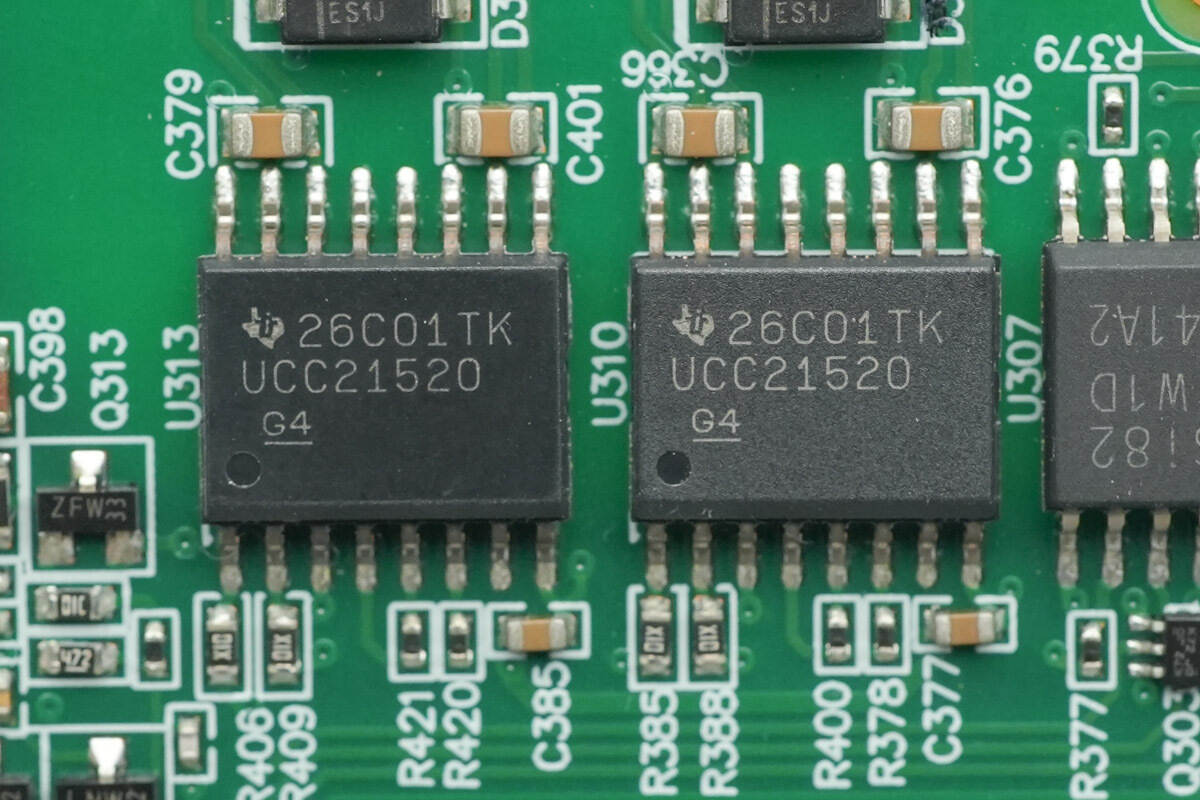
The digital isolators are from TI, model UCC21520. They are isolated dual-channel gate drivers with 5.7 kV RMS isolation, capable of 4 A peak sourcing current and 6 A peak sinking current. They can drive MOSFETs, IGBTs, and SiC MOSFETs, support switching frequencies up to 5 MHz, and are packaged in SOIC16DW.

The current sensing chip is from TI, marked BJL, model INA198. It is a shunt-monitoring amplifier supporting a common-mode voltage range of –16 V to 80 V, with a bandwidth of 500 kHz, and is packaged in SOT-23.
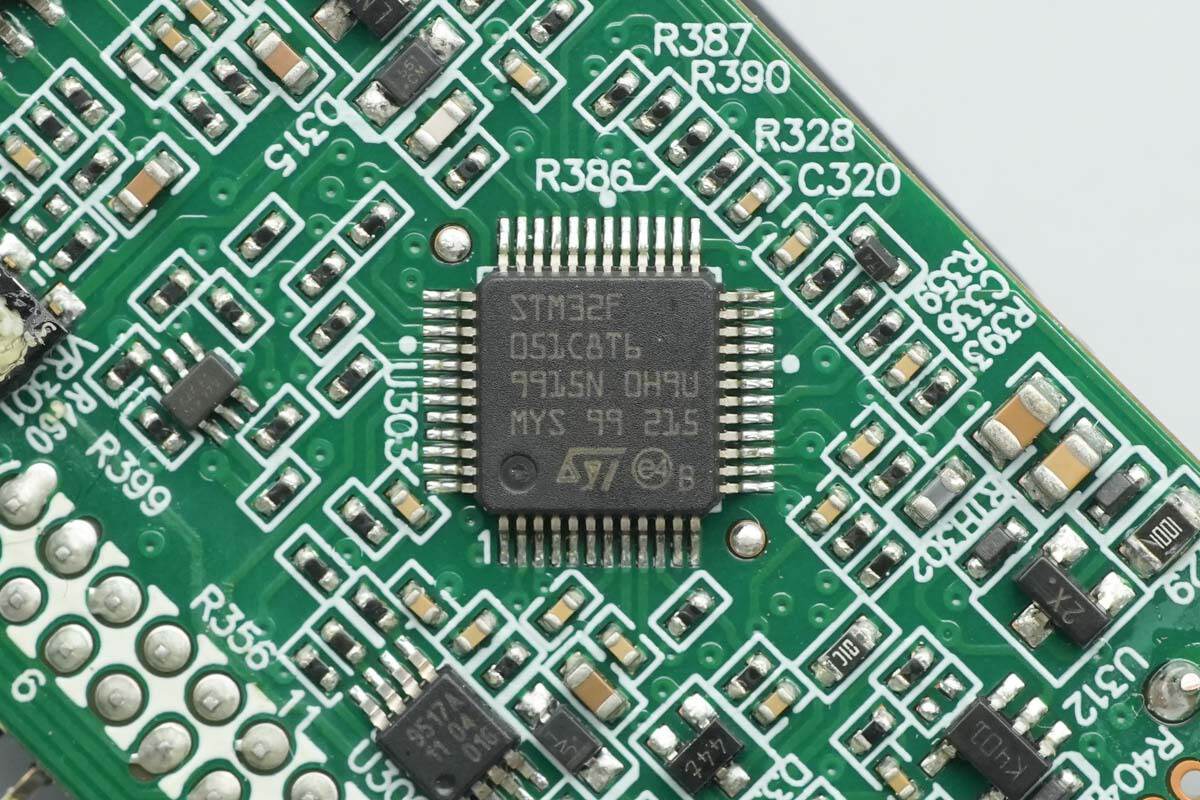
The MCU is from STMicro, model STM32F051C8T6. It features an ARM Cortex-M0 CPU running at 48 MHz, with 64 KB of Flash memory and 8 KB of SRAM. It supports motion control and CEC functions, and is packaged in LQFP48.
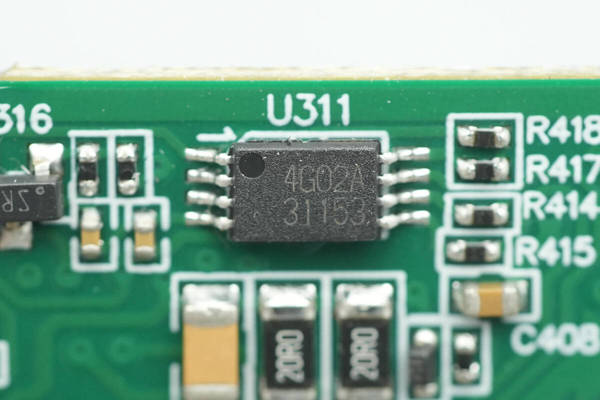
The memory is from ROHM, marked 4G02A, model BR24G02-3A. It has a capacity of 256 B, supports an operating voltage of 1.6–5.5 V, and is packaged in TSSOP-B8.

The digital isolator is from NOVOSENSE, model NSi8241W1D. It is a bidirectional, four-channel digital isolator supporting a data rate of 150 Mbps, and is packaged in SOP16.

The buffer is from NXP, model PCA9517A. It is an I²C/SMBus buffer with two bidirectional channels and is packaged in TSSOP8.

The Op-Amp used is the TI OPA171.
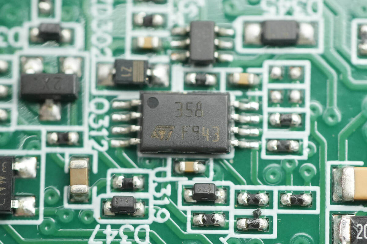
The Op-Amp is from STMicro, model LM358. It is a low-power dual operational amplifier, packaged in MiniSO8.

The Op-Amp is from STMicro, marked K401, model TS321ILT. It is suitable for single-supply applications and is packaged in SOT23-5.

The voltage comparator is from STMicro, model LM393. It is a low-power dual voltage comparator, packaged in MiniSO8.

The regulator used is the Microchip MIC52093.3YS.

The electronic fuse is from Onsemi, marked 5021, model NIS5021. It is a high-performance electronic fuse IC rated for 12 V operation, featuring overcurrent and overtemperature protection, with an integrated 14 mΩ switch, and is packaged in WDFN 1.0 × 0.4 mm.
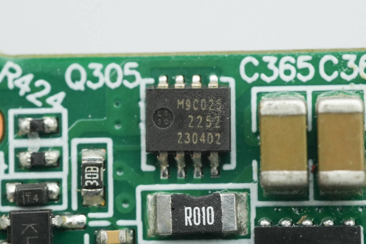
The MOSFET is from Nexperia, marked M9C025, model PSMN9R0-25MLC. It is an NMOS device rated at 25 V, with an on-resistance of 7.55 mΩ, and is packaged in LFPAK33.

Close-up of the 100 mΩ current-sense resistor and the filter capacitors.
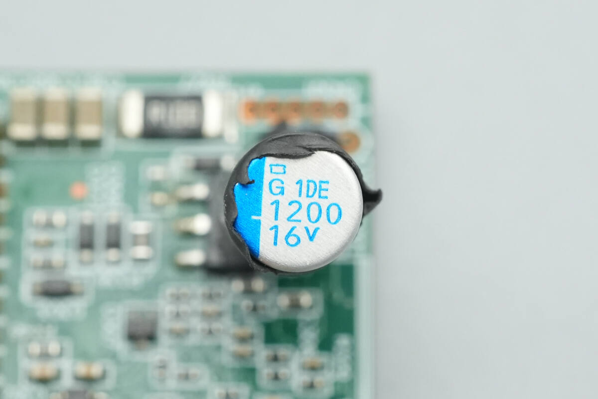
The filter capacitor is rated at 1200 μF and 16 V.
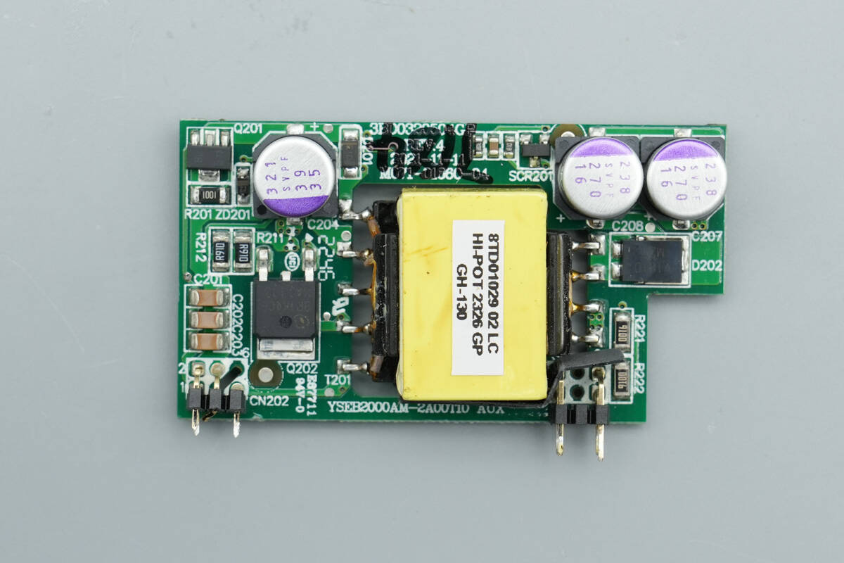
The front side of the standby power supply PCB features the primary MOSFET, filter capacitors, transformer, and rectifier diode.

The backside features the master control chip and a feedback optocoupler.
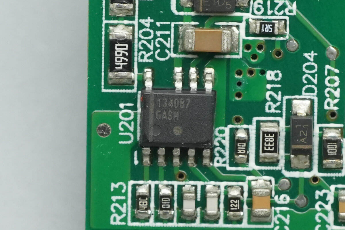
The master control chip is from Onsemi, model NCP1340B7. It is a highly integrated QR controller with built-in X2 capacitor discharge and overtemperature protection, packaged in SOIC-9NB.

The filter capacitor powering the master control chip is from Panasonic, part of the SVPF series of conductive polymer aluminum solid capacitors, rated at 39 μF and 35 V.

The primary MOSFET is from Infineon, marked 8R1K4CE, model IPD80R1K4CE. It is an NMOS device rated at 800 V, with an on-resistance of 1400 mΩ, and is packaged in TO-252.
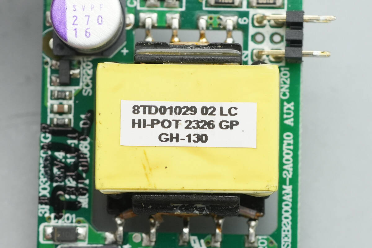
The transformer magnetic core is insulated with tightly wound tape.

The PCBA module is hollowed out to reduce its thickness.

The LITEON LTV1008 optocoupler is used for output voltage feedback.
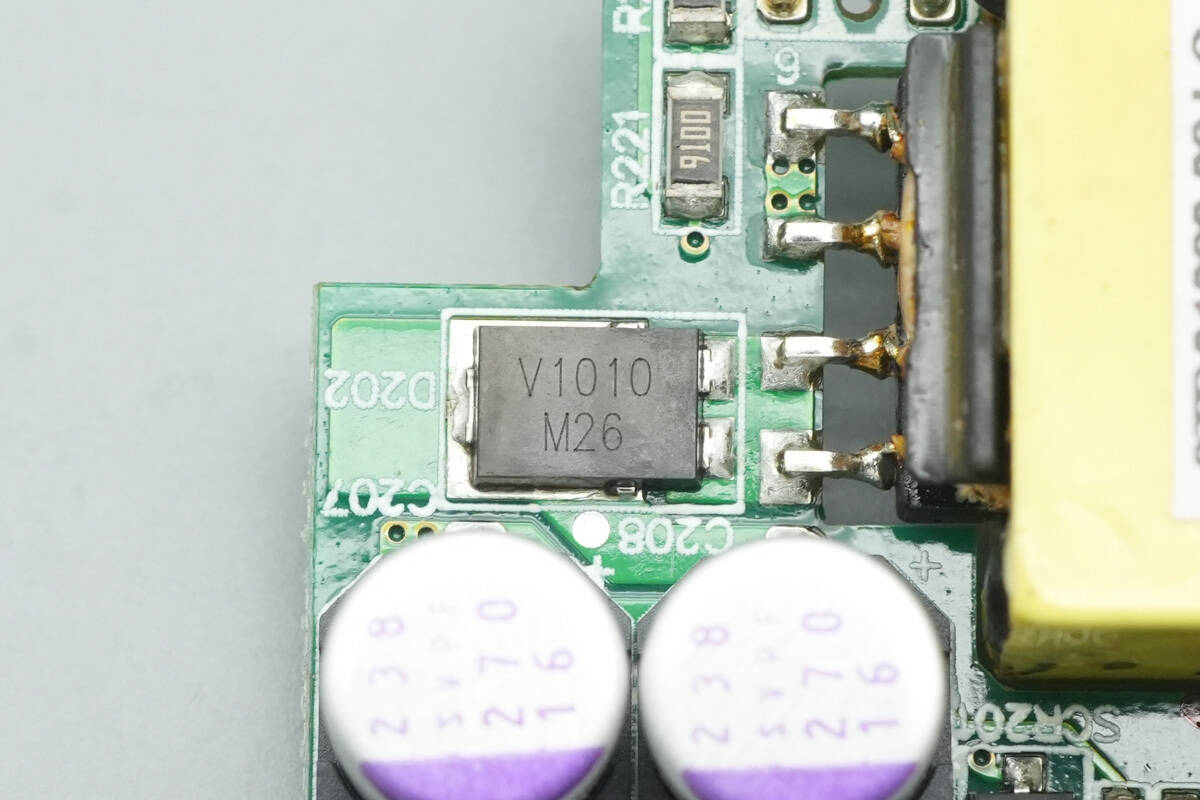
The rectifier is from VISHAY, marked V1010, model V10P10, rated at 10 A and 100 V, and packaged in TO-277A.
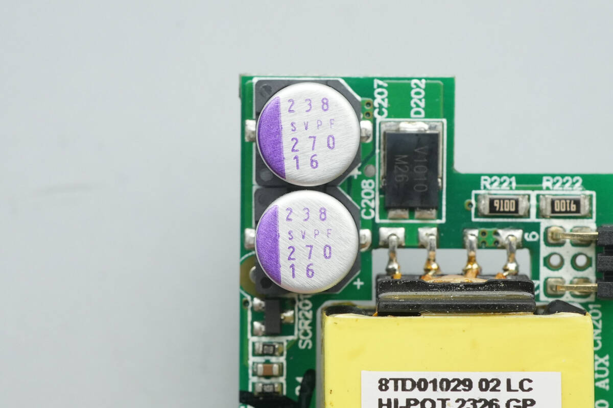
The output filter capacitors are rated at 270 μF and 16 V.
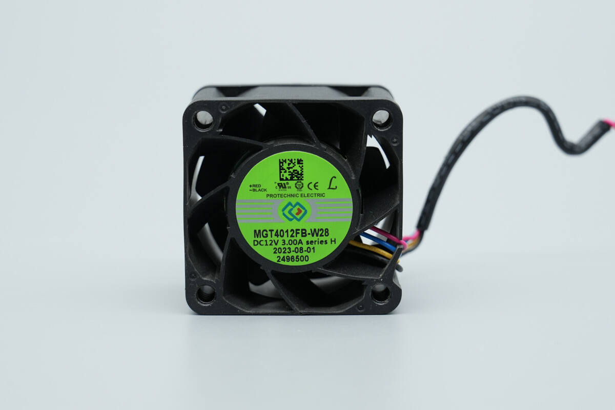
The cooling fan is from PROTECHNIC, model MGT4012FB-W28, rated at 12 V and 3 A, and features static blades.

Well, those are all components of the 3Y POWER 1600W SiC Server Power Supply.
Summary of ChargerLAB

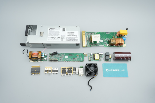
Here is the component list of the 3Y POWER 1600W SiC Server Power Supply for your convenience.
The power supply is model YSEF1600EM, supporting 100–240 V AC input and 190–310 V DC input. Its main output is 12.2 V at 130 A, and the standby power supply output is 12 V at 2 A.
After taking it apart, we found that it uses a PFC + full-bridge LLC + synchronous rectification architecture. The PFC controller is an STMicro STM32F334K8T6, the LLC controller is an Onsemi NCP4390, and an STMicro STM32F051C8T6 handles system-wide control.
Both the PFC and LLC MOSFETs are from STMicro, using STW40N60M2 in combination with STP43N60DM2. The PFC rectifiers are Onsemi FFSD0665A, while the synchronous rectifiers are Infineon BSC016N06NS. The SiC diodes and synchronous rectifier drivers are handled by Onsemi NCP81071B, and the LLC switching MOSFETs are driven by a TI UCC21520 driver.
The output control MOSFETs use Nexperia PSMN1R6-30MLH. The standby power supply IC is an Onsemi NCP1340B7, with the standby power MOSFET being an Infineon IPD80R1K4CM. The rectifier uses a VISHAY V10P10 diode. The power supply employs Japanese-brand capacitors for filtering, and the overall build quality and component selection are solid.
Related Articles:
1. Teardown of BULL 67W GaN Digital Display Power Strip (GNV-ML1676)
2. Teardown of KOAKUMA 3-in-1 Display Qi2.2 Wireless Charger
3. Teardown of Lenovo Legion 300W Original Adapter (ADL300SDC3A)